Embed Size (px)
Citation preview

ANTENNA SELECTION FOR A PUBLIC SAFETY COGNITIVE RADIO
Akilah L. Hugine
Thesis submitted to the Faculty of the Virginia Polytechnic Institute and State University in partial fulfillment of the
requirement for the degree of
Master of Science in
Electrical Engineering
Dr. Charles W. Bostian, Chair Dr. Wayne Scales
Dr. Allen MacKenzie
May 2006
Key Words: Public Safety Cognitive Radio, Quadband Antenna

ANTENNA SELECTION FOR A PUBLIC SAFETY COGNITIVE RADIO
Akilah L. Hugine
ABSTRACT
Ever since the dawn of radio communication systems, the antenna has been the key
component in the construction and performance of every wireless system. With the proliferation
of new radio systems, a cognitive radio is a radio that has the capability to sense, learn, and
autonomously adapt to its environment. The hardware components are essential to optimizing
performance. Antenna hardware for cognitive radio applications presents distinctive problems,
since in theoretical terms, a cognitive radio can operate anywhere in the spectrum.
The purpose of this thesis is to investigate a particular type of cognitive radio system and
examine the potential affects the antenna will have on the system. The thesis will provide an
overview of fundamental antenna properties, the performance characteristics of the particular
antenna used in this research, and the system characteristics when the antenna is integrated. This
thesis will also illustrate how the antenna and its properties affect the overall public safety
cognitive radio performance. This information can be used to establish antenna selection criteria
for optimum system performance.

ACKNOWLEDGEMENTS
Thanks be to God, who in Christ always leads us in triumph " (II Corinthians 2: 14)
First and foremost I would like to thank my advisor Dr. Charles Bostian for his guidance and
support throughout this research. There are no words to express how much I appreciate
everything he has done for me. He has always motivated me to strive to do my best. His advice
and encouragement during my time here at Virginia Tech was very invaluable. He has certainly
made a lasting impression on me and I will be forever grateful to have had the opportunity to
work with him.
I would also like to thank Dr. Wayne Scales and Dr. Allen MacKenzie for their willingness to
serve on my committee and for the helpful feedback they provided on my thesis. Appreciation is
extended to Dr. Davis for his assistance with the antenna measurements that contributed to this
work.
Special thanks are expressed to all of the team members of the Center for Wireless
Telecommunications (CWT); without them, this work would not have been possible. Especially
Bin, Tom, Daivd M., and David S., my sincere gratitude goes out to each of you, your enthusiasm
for research is truly a motivation. Also thanks to Judy for helping me whenever I had questions
and Rarick for reviewing my thesis document.
Finally, I would like to thank my family and friends for their continued support and
encouragement during this effort and also life. I would especially like to thank my parents for
giving me, much needed advice and immense strength and support every time I needed it; and for
their constant reminders that if I just put everything in GODs hands it will work out in the end.

-iv-
Contents
ABSTRACT...................................................................................................... ..ii
ACKNOWLEDGEMENTS............................................................................................ iii
List of Figures ............................................................................................................. vii
List of Tables ............................................................................................................... iv
1 Introduction................................................................................................................1
1.1 Organization of Thesis .......................................................................................2
1.2 References.........................................................................................................2
2 Cognitive Radio (CR) .........................................................................................3
2.1 CR Concept........................................................................................................3
2.1.1 Cognition Cycle..................................................................................................4
2.2 CR Criteria & Capabilities ..................................................................................6
2.2.1 Sense.................................................................................................................6
2.2.2 Adapt..................................................................................................................6
2.2.3 Learn..................................................................................................................6
2.3 Cognitive Radio Advantages & Disadvantages..................................................7
2.3.1 Advantages ........................................................................................................7
2.3.2 Disadvantages ...................................................................................................9
2.4 CWT Cognitive Engine.......................................................................................9
2.5 References.......................................................................................................11
3 Typical Communication Antennas....................................................................13
3.1 Performance Criteria for Antennas...................................................................13
3.1.1 Radiation Patterns............................................................................................13
3.1.2 Gain .................................................................................................................14
3.1.3 VSWR ..............................................................................................................15
3.1.4 Bandwidth ........................................................................................................15
3.2 Types of Antennas ...........................................................................................16
3.2.1 Monopole .........................................................................................................16
3.2.2 Diamond & Rounded Diamond.........................................................................16
3.2.3 Biconical...........................................................................................................17
3.2.4 Summary..........................................................................................................19

-v-
3.3 References.......................................................................................................20
4 Public Safety Bands.........................................................................................21
4.1 Specific Public Safety Operating Bands...........................................................21
4.1.1 Law Enforcement .............................................................................................24
4.1.2 Emergency Medical Services (EMS)................................................................24
4.1.3 Fire Services ....................................................................................................25
4.1.4 Summary of Public Safety Bands.....................................................................25
4.2 Virginia Tech Public Safety Bands ...................................................................26
4.3 References.......................................................................................................27
5 Characteristics of the SRH999 Quadband Antenna.........................................28
5.1 Diamond Antenna SRH999 Quadband Antenna..............................................28
5.2 Antenna Measurement Setup...........................................................................29
5.2.1 Measurement 1: 50-500 MHz No Ground Plane ..............................................30
5.2.2 Measurement 2: 50 -2000 MHz No Ground Plane ...........................................30
5.2.3 Measurement 3: 50-2000MHz Circular Ground Plane .....................................31
5.2.4 Measurement 4: 50-2000 MHz Metal Box Ground Plane.................................32
5.3 Antenna Performance Characteristics..............................................................32
5.3.1 Antenna Impedance Characteristics ................................................................32
5.3.2 Antenna Impedance Magnitude Characteristics...............................................44
5.3.3 Antenna VSWR Characteristics .......................................................................49
5.3.4 Antenna Power Characteristics........................................................................53
5.4 References.......................................................................................................55
6 Effects of the Antenna Characteristics on Public Safety CR ............................56
6.1 System Components........................................................................................56
6.1.1 GNU Radio.......................................................................................................56
6.2 Experiment Architecture...................................................................................58
6.2.1 USRP Output Impedance.................................................................................60
6.2.2 Relative Radiated Power..................................................................................62
6.2.3 Angle of Maximum Radiation ...........................................................................66
6.3 Evaluation of Antenna Affects ..........................................................................69
6.3.1 Implementing Antenna Hardware with GNU Radio ..........................................69

-vi-
6.4 References.......................................................................................................70
7 CONCLUSIONS...............................................................................................72
VITA 73

-vii-
List of Figures Figure 2-1 Knobs and Meters Methodology [11] ............................................................4
Figure 2-2 Cognition Cycle [1] ..........................................................................................5
Figure 2-3 Spectral Utilization during One Day (50 MHz1 GHz) [6]................................8
Figure 2-4 CWT Cognition Loop [9]................................................................................10
Figure 3-1 Impedance of Diamond & Rounded Diamond [6] .........................................17
Figure 3-2 Impedance of a Biconical Dipole..................................................................18
Figure 5-1 SRH999 Quadband HT Antenna [2].............................................................28
Figure 5-2 1st Measurement: 50-500 MHZ; No Ground Plane.......................................30
Figure 5-3 2nd Measurement Setup for 50-1200 MHZ with No Ground Plane ...............31
Figure 5-4 3rd Measurement: 50-1200 MHZ; Circular Ground Plane.............................31
Figure 5-5 4th t Measurement: 50-1200 MHZ; Metal Box Ground Plane........................32
Figure 5-6 Sample Representation of Network Analyzer Data ......................................33
Figure 5-7 Real Impedance 1st Measurement: 50-500 MHZ; No Ground Plane............35
Figure 5-8 Imaginary Impedance 1st Measurement: 50-500 MHZ; No Ground Plane.....36
Figure 5-9 Real Impedance 2nd Measurement: 50-1200 MHZ; No Ground Plane .........37
Figure 5-10 Imaginary Impedance 2nd Measurement: 50-1200 MHZ; No Ground Plane37
Figure 5-11 Real Impedance 3rd Measurement: 50-1200 MHZ; Circular Ground Plane38
Figure 5-12 Imaginary Impedance 3rd Measurement: 50-1200 MHZ; Circular Ground
Plane.......................................................................................................................39
Figure 5-13 Real Impedance 4th Measurement: 50-1200 MHZ; Metal Box Ground Plane
................................................................................................................................40
Figure 5-14 Imaginary Impedance 4th Measurement: 50-1200 MHZ; Metal Box Ground
Plane.......................................................................................................................41
Figure 5-15 Real Impedance: All Measurements ..........................................................42
Figure 5-16 Imaginary Impedance All Measurements ...................................................43
Figure 5-17 Magnitude Impedance 1st Measurement: 50-500 MHZ; No Ground Plane..44
Figure 5-18 Magnitude Impedance 2nd Measurement: 50-1200 MHZ; No Ground Plane
................................................................................................................................45

-viii-
Figure 5-19 Magnitude Impedance 3rd Measurement: 50-1200 MHZ; Circular Ground
Plane.......................................................................................................................46
Figure 5-20 Magnitude Impedance 4th Measurement: 50-1200 MHZ; Metal Box Ground
Plane.......................................................................................................................47
Figure 5-21 Impedance Magnitude All Measurements ..................................................48
Figure 5-22 VSWR 1st Measurement: 50-500 MHZ; No Ground Plane ........................49
Figure 5-23 VSWR 2nd Measurement: 50-1200 MHZ; No Ground Plane ...................50
Figure 5-24 VSWR 3rd Measurement: 50-1200 MHZ; Circular Ground Plane ...............51
Figure 5-25 VSWR 4th Measurement: 50-1200 MHZ; Metal Box Ground Plane.............52
Figure 5-26 VSWR All Measurements............................................................................53
Figure 6-1 Typical SR Block Diagram [3].......................................................................57
Figure 6-2 USRP Circuit Board and Block Diagram [2] .................................................58
Figure 6-3 Portion of USRP Transmitter Output Circuitry [2] .........................................59
Figure 6-4 Schematic of Impedance seen by GNU Radio.............................................60
Figure 6-5 Real, Imaginary, Magnitude vs. Frequency of Impedance Presented by GNU
Radio.......................................................................................................................61
Figure 6-6 Schematic for Determining Radiated Power.................................................62
Figure 6-7 Radiated Power All Measurements ..............................................................64
Figure 6-8 Radiated Power for Test Measurements ......................................................65
Figure 6-9 Defining Theta..............................................................................................67
Figure 6-10 Angle of Maximum Radiation .....................................................................68
Figure 6-11 Antenna Hardware with USRP....................................................................69
Figure 6-12 Antenna Hardware Test Setup...................................................................70

List of Tables
-ix-
List of Tables
Table 3-1 Some Typical Radiation Patterns...14
Table 3-2 Commonly Used Antennas ............................................................................19
Table 4-1 Public Safety Personnel [1] ............................................................................21
Table 4-2 Spectrum Utilization [4] ..................................................................................23
Table 4-3 Sample of Common Police Frequencies [3] ...................................................24
Table 4-4 Sample of Common Medical Frequencies [3].................................................25
Table 4-5 Partial Listing of Fire Department Frequencies [2 & 3] ...................................25
Table 4-6 Public Safety Bands [2] ..................................................................................26
Table 4-7 Virginia Tech Frequency Bands [5] ................................................................27
Table 5-1 Operating bands of the SRH999 antenna ......................................................29
Table 5-2 Measured Received Power between Tx/Rx....................................................54
Table 6-1 Maximum Radiated Power ............................................................................66

1 Introduction
-1-
1 Introduction
In the 21st century where new facets of communication are being explored, advances in
radio technology continue to revolutionize the face of wireless communications and technology.
There is a continuous demand for data transmission at higher rates and over longer distances.
The need for secure and robust communications is becoming more apparent. Wireless and
mobile communication systems are at the forefront of current research activities. In addition,
ever larger numbers of people are relying on wireless technology, either directly or indirectly.
Since the first demonstration of wireless technology in a practical radio communication system
by Guglielmo Marconi, the antenna has been a key building block in the construction of every
communication system [1].
It is important that engineers designing wireless communications systems have some
fundamental knowledge of antenna performance and radio wave propagation characteristics. This
knowledge is essential to the proper selection of system antennas to ensure system coverage and
performance. A properly selected antenna system has the capability of improving overall system
performance and may lead to a reduction in system cost. Conversely, a poorly selected antenna
system may degrade system performance.
The purpose of this thesis is to investigate the factors that influence antenna selection for a
public safety cognitive radio and to report in detail on the properties of the commercial antenna
that I selected. In the document, I will review the basic concepts of cognitive radio and explain
the approach that my research group has taken to develop a working prototype. The frequency
agility of the public safety cognitive radio requires an antenna capable of operating in at least
four bands between 50 MHz and 1 GHz, and one with a form factor suitable for mounting on a
hand held radio. After reviewing antenna characteristics in general, I will focus on the antennas
terminal impedance and resulting VSWR, the interaction of the antenna with the output network
of the GNU radio transmitter, and the most important feature of the antennas radiation pattern,
the direction of maximum radiation. I will also report on some informal indoor measurements of
radio link performance using this antenna. As far as I am aware, this is the first investigation of
these topics for a cognitive radio.

1 Introduction
-2-
1.1 Organization of Thesis
Following this introduction, Chapter 2 introduces the concept of Cognitive Radio and
describes the VT Cognitive Radio Platform. Chapter 3 gives a description of performance criteria
for antennas. Chapter 4 aims to illustrate a real world example by showing how an antenna
affects the cognitive radio platform. Chapter 5 indicates what possible antenna solutions are
available for CR. The section also aims to discuss the tradeoffs needed for antenna performance
of a cognitive radio and also certain issues that may arise for selecting a CR antenna. The final
chapter presents some conclusions and recommendations for future work.
1.2 References
[1] O. Dunlap, Marconi: The Man and His Wireless. New York: Arno Press, 1971.

Cognitive Radio (CR) - CR Concept - Cognition Cycle
-3-
2 Cognitive Radio (CR) The objective of this chapter is to discuss the concept of cognitive radio and describe the CR
SDR platform being developed by the Center for Wireless Telecommunications (CWT) at
Virginia Tech.
2.1 CR Concept
The term Cognitive Radio was first coined by Joseph Mitola as the point in which wireless
personal digital assistants (PDAs) and the related networks are sufficiently computationally
intelligent about radio resources and related computer-to-computer communications to: (a) detect
user communications needs as a function of use context, and (b) to provide radio resources and
wireless services most appropriate to those needs [5]. However the concept of CR is not limited
strictly to wireless devices such as PDAs. There has been a lot of ambiguity over how to
actually define the concept of CR. This is apparent by the number of proposed definitions give
by various organizations and prominent individuals [1]. The working definition of CR.
constructed by the SDR Forum Cognitive Radio Working Group, allows for future evolution of
CR as well as strictly defining the concept:
A Cognitive Radio is a software-defined radio that possesses the attributes of being RF and spatially aware with the ability to autonomously adjust to its environment accordingly (frequency, power, & modulation). [2]
Cognitive radios have the capability to sense their environment and learn how to adapt to
various situations. This allows a CR to handle unanticipated signals, channels, and events that
may arise. Thus a CR is able to automatically select the best waveform for a radio transmission
and is even able to delay or bring forward certain transmissions depending on the currently or
future available resources. The learning and reasoning capabilities needed for CRs to fulfill this
goal which would more than likely be implemented in software as a high layer functionality have
been investigated [4][5]. In more piratical terms the idea of cognitive radio can be thought of in
the analogy knobs (observable parameters) and meters (writable parameters) [9]. See Figure
2-1.

Cognitive Radio (CR) - CR Concept - Cognition Cycle
-4-
Figure 2-1 Knobs and Meters Methodology [11]
Meters are all possible outputs or information that can be available from the radio. Knobs
are all possible actions that the radio can take, in other words how the radio adjusts what is being
read. The most important use for the meters of the cognitive radio is sensing the RF
environment, determining what signals are present and their properties. This can be termed
signal detection and signal classification. Signal detection is the process of collecting a signal, in
the presence of noise, so that an action can be performed. Signal classification is the process of
identifying the signal and determining its technical characteristics.
2.1.1 Cognition Cycle
CR can better be explored by introducing the cognition cycle, which explains what a
cognitive radio is. Since being introduced by Mitola [5], the operation of cognitive radios has
been frequently illustrated by the cognition cycle illustrated in Figure 2-2. The cognition cycle is
a state machine that resides in the cognitive radio and defines how the radio learns about and
reacts to its operating environment.
Channel Statistics Cognitive Engine Radio Parameters
Radio TX
Radio RX
Old Knobs and Meters
New Knobs
Old Knobs and Meters
New Knobs

Cognitive Radio (CR) - CR Concept - Cognition Cycle
-5-
Figure 2-2 Cognition Cycle [1]
The first step of the cognition cycle is to observe the outside world. The radio receives
information about the operating environment. This information is then analyzed to determine the
meaning of what is being observed. The cognition cycle determines the importance of certain
information. Based on this information, the radio generates and evaluates alternatives that can be
employed. After assessing the various alternatives it decides which method will presumably
improve the system. The radio then implements the chosen alternative by adjusting its resources
and performing the appropriate signaling. These changes are then reflected in a message
presented by the cognitive radio. Throughout the process, the radio is using these observations
and decisions to improve its operation. The radio is learning about the outside world and is
evaluating the users needs. This will help to improve the performance of the system, because

Cognitive Radio (CR) - CR Criteria & Capabilities - Sense
-6-
now the CR can enhance the system by creating new modeling states by generating new
alternatives.
2.2 CR Criteria & Capabilities
Three major features define a cognitive radio. A CR must be able to sense, adapt, and learn
from its environment. These are the characteristics that make CR unique from other spectrum
sharing and wireless communication techniques.
2.2.1 Sense
The radio has awareness of what kind of environment it is currently or potentially
operating in. A CR must be able to sense wireless channels and user networks across the
multiple signal dimensions of time, frequency and physical space [7]. This information is key to
opportunistically providing wireless links that best meet the user requirements and needs.
2.2.2 Adapt
Adaptability is a key concept when you refer to mobile networks and limited resources for
transmitting signals. Cognitive radios are aware of their environment and intelligently adapt their
performance to the user's needs [8]. The radio knows how to adjust to the spectral environment
and dynamically change modulation and frequency to use unoccupied spectrum that avoids
congestion and jamming. The knowledge of the operational environment is referred to as
situation awareness and includes information about the physical environment, RF channel, radio
resources, and user requirements.
2.2.3 Learn
The concept of a radio that can learn is a fundamental change in the perception of typical
radio systems. The ability of a CR to learn from its previous experience is what sets this
particular technology apart from any existing system. The learning processes of a CR allow the
system to know about certain environmental parameters so that it can adjust itself accordingly
when the same situation occurs.

Cognitive Radio (CR) - Cognitive Radio Advantages & Disadvantages - Advantages
-7-
2.3 Cognitive Radio Advantages & Disadvantages
2.3.1 Advantages
There are several advantages of a technology as ubiquitous as CR, but there are three
essential aspects of why CR is so important. The main three advantages of CR are:
! Improved link performance
! Improved spectrum utilization
! Potential cost reduction
The idea of improved link reliability arises in the situation where you lose a signal or
connection in rural areas or vicinities where coverage is minimal. CR could essentially play a
major role in the improvement of link performance by being able to adapt to bad channels or
connections. The technology also has the capability of improving on a good channel by
increasing the data rate. The CR looks at its available alternatives and learns the best course of
action for the situation. Another aspect that CR will help improve, is indirectly related to link
reliability regarding the issue of interoperability. Interoperability refers to the ability of different
types of wireless devices and applications to work together effectively, without prior
communication, in order to exchange information in a useful and meaningful manner. As an
example, suppose a national emergency occurs and public safety personnel from different parts of
the U.S. respond to the disaster, all jurisdictions will be able to communicate seamlessly without
interference. CR will become a must-have technology for situations as these with its, frequency
agility and/or flexibility, the ability to enhance interoperability between different radio standards,
and the capability to sense the presence of interferers [12]. With spectrum sharing capabilities,
cognitive radios can prove their effectiveness by utilizing some of the existing spectrum that is
not widely used while help in maintaining call priority and response time. The spectrum is
already allocated for the U.S.; the major problem is not spectrum scarcity but access and
utilization of it.
Cognitive Radio (CR) - Cognitive Radio Advantages & Disadvantages - Advantages
-8-
Figure 2-3 Spectral Utilization during One Day (50 MHz1 GHz) [6]
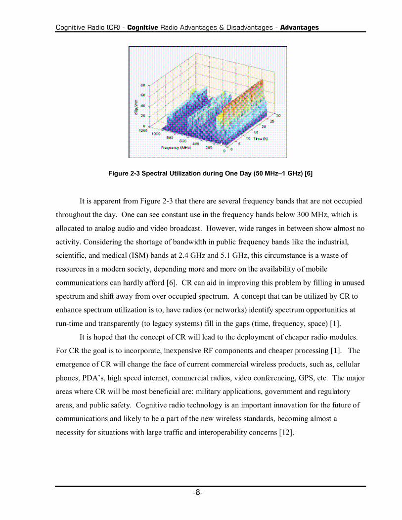
It is apparent from Figure 2-3 that there are several frequency bands that are not occupied
throughout the day. One can see constant use in the frequency bands below 300 MHz, which is
allocated to analog audio and video broadcast. However, wide ranges in between show almost no
activity. Considering the shortage of bandwidth in public frequency bands like the industrial,
scientific, and medical (ISM) bands at 2.4 GHz and 5.1 GHz, this circumstance is a waste of
resources in a modern society, depending more and more on the availability of mobile
communications can hardly afford [6]. CR can aid in improving this problem by filling in unused
spectrum and shift away from over occupied spectrum. A concept that can be utilized by CR to
enhance spectrum utilization is to, have radios (or networks) identify spectrum opportunities at
run-time and transparently (to legacy systems) fill in the gaps (time, frequency, space) [1].
It is hoped that the concept of CR will lead to the deployment of cheaper radio modules.
For CR the goal is to incorporate, inexpensive RF components and cheaper processing [1]. The
emergence of CR will change the face of current commercial wireless products, such as, cellular
phones, PDAs, high speed internet, commercial radios, video conferencing, GPS, etc. The major
areas where CR will be most beneficial are: military applications, government and regulatory
areas, and public safety. Cognitive radio technology is an important innovation for the future of
communications and likely to be a part of the new wireless standards, becoming almost a
necessity for situations with large traffic and interoperability concerns [12].

Cognitive Radio (CR) - CWT Cognitive Engine
-9-
2.3.2 Disadvantages
With any emerging technology there are drawbacks that can potentially affect the
development of the system. Key problems that arise for CR include:
! Encompasses the same drawbacks as software defined radio
! Loss of control
! Regulatory concerns
! Significant research remains to be done to realize commercially practical
cognitive radios [11]
With any software define radio based technology there are always complexity drawbacks. Since
the core of CR resided with software defined radio, CR inherits most of the same problems
associated with software defined radio. Some of the drawbacks associated with software defined
radio are:
! Security
! Software reliability
! Keeping up with higher data rates [1]
The process of CRs sense, learn, and adapt cycle changes the outside world for other cognitive
radios with each cycle. This can potentially result in loss of control if a group of radios interact
with each other causing chaotic networks [1]. As far as regulatory concerns apply to CR the
current FCC regulations are not specified or designed for CR use. The fear is that regulations
will retard the development of cognitive radio or actually reduce available spectrum [1]. The
concept of CR is still evolving and there are many research areas that need to be addressed for the
systems. This includes: information collection and modeling; decision processes; learning
processes; hardware support [11].
2.4 CWT Cognitive Engine
The radio architecture and functionality of the CWT cognitive engine can be expressed as
an intelligent agent that controls a software defined radios set of Meters and Knobs [9]. The
CWT cognitive model is based on biologically motivated techniques, such as the use of genetic
Cognitive Radio (CR) - CWT Cognitive Engine
-10-
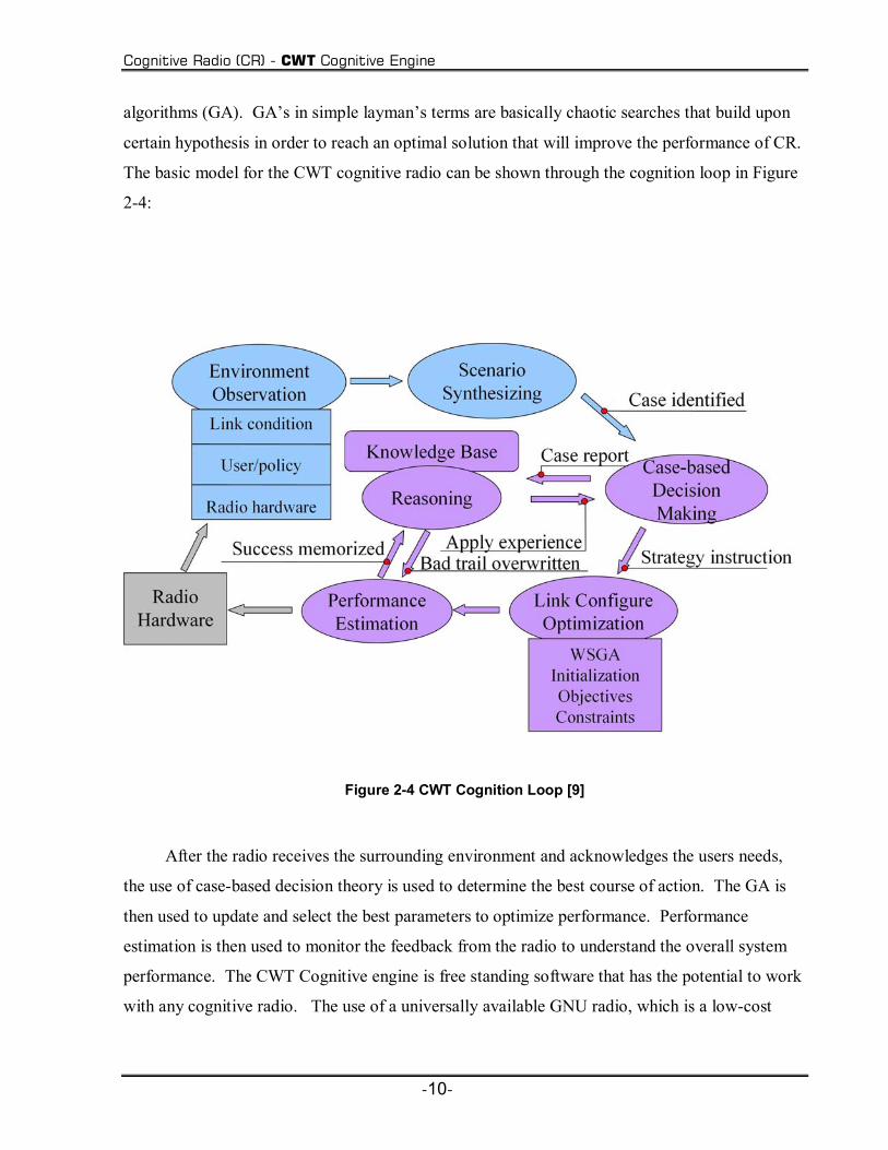
algorithms (GA). GAs in simple laymans terms are basically chaotic searches that build upon
certain hypothesis in order to reach an optimal solution that will improve the performance of CR.
The basic model for the CWT cognitive radio can be shown through the cognition loop in Figure
2-4:
Figure 2-4 CWT Cognition Loop [9]
After the radio receives the surrounding environment and acknowledges the users needs,
the use of case-based decision theory is used to determine the best course of action. The GA is
then used to update and select the best parameters to optimize performance. Performance
estimation is then used to monitor the feedback from the radio to understand the overall system
performance. The CWT Cognitive engine is free standing software that has the potential to work
with any cognitive radio. The use of a universally available GNU radio, which is a low-cost
Cognitive Radio (CR) - References
-11-
radio developed specifically for building and deploying software defined radios, will serve as the
SDR platform. We are testing it with the GNU radio platform because it is open source,
inexpensive, and currently available. Since the GNU radio system serves as the SDR platform,
which the CWTs cognitive engine controls, this will be the basis of my real world example on
how antennas affect the performance of a public safety CR. There will be a practical assessment
of the performance advantages or disadvantages of antenna hardware on CR.
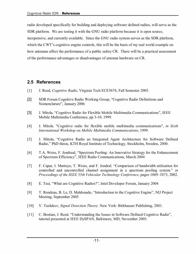
2.5 References
[1] J. Reed, Cognitive Radio, Virginia Tech ECE5674, Fall Semester 2005. [2] SDR Forum Cognitive Radio Working Group, Cognitive Radio Definitions and
Nomenclature, January 2006 [3] J. Mitola, Cognitive Radio for Flexible Mobile Multimedia Communications, IEEE
Mobile Multimedia Conference, pp 3-10, 1999. [4] J. Mitola. "Cognitive radio for flexible mobile multimedia communications", in Sixth
International Workshop on Mobile Multimedia Communications, 1999. [5] J. Mitola, Cognitive Radio an Integrated Agent Architecture for Software Defined
Radio, PhD thesis, KTH Royal Institute of Technology, Stockholm, Sweden, 2000. [6] T.A. Weiss, F. Jondreal, Spectrum Pooling: An Innovative Strategy for the Enhancement
of Spectrum Efficiency, IEEE Radio Communications, March 2004 [7] F. Capar, I. Martoyo, T. Weiss, and F. Jondral. Comparison of bandwidth utilization for
controlled and uncontrolled channel assignment in a spectrum pooling system. in Proceedings of the IEEE 55th Vehicular Technology Conference, pages 10691073, 2002.
[8] E. Tsui, What are Cognitive Radios?, Intel Developer Forum, January 2004 [9] T. Rondeau, B. Le, D. Maldonado, Introduction to the Cognitive Engine, NIJ Project
Meeting, September 2005 [10] V. Tuzlukov, Signal Detection Theory. New York: Birkhauser Publishing, 2001. [11] C. Bostian, J. Reed, Understanding the Issues in Software Defined Cognitive Radio,
tutorial presented at IEEE DySPAN, Baltimore, MD, November 2005.

Cognitive Radio (CR) - References
-12-
[12] D. Maldonado; Bin Le; A. Hugine; T.W. Rondeau; C.W. Bostian,, Cognitive radio applications to dynamic spectrum allocation: a discussion and an illustrative example, IEEE DySPAN, Page(s):597 600, November 2005

Typical Communication Antennas - Performance Criteria for Antennas - Radiation Patterns
-13-
3 Typical Communication Antennas Cognitive radios need antennas that cover a wide frequency range. Antennas serve as
transducers between electromagnetic wave travelling in free space and guided electromagnetic
signal in circuits [1]. As such, they play a critical role in the performance of CR systems. If you
ignore the antenna, then the radio may not attain maximum effective range. An effective antenna
solution increases the range and corresponding coverage of a CR.
3.1 Performance Criteria for Antennas
There are many characteristics of antennas that determine whether the antenna is efficient
or not. Some of the most important characteristics of antennas are: gain, size, radiation pattern,
bandwidth, and voltage standing wave ratio (VSWR).
3.1.1 Radiation Patterns
The radiation pattern of an antenna is a plot of the relative power versus angle. The
radiation pattern defines the radiating characteristics of the antenna. The most basic radiation
pattern is isotropic, which means the antenna transmits radio waves in all directions equally. An
isotropic radiation pattern resembles the shape of a beach ball, with an antenna at its center. An
isotropic antenna is an ideal antenna that radiates power with unit gain uniformly in all directions
and is often used as a reference for antenna gains in wireless systems [3]. There is no actual
physical isotropic antenna.
The more common antenna types for wireless communications have omni-directional and
directional radiation patterns. Omni-directional antennas propagate RF signals in all directions
equally on a horizontal plane are directional in the vertical plane [2]. Typical omni-directional
antennas have gains ranging up to 6 dBi. The gain of an omni-directional antenna can be
increased by narrowing the beamwidth in the vertical or elevation plane [4].
Higher gain antennas will have a narrower beam width, which limits coverage on the
sides of the antennas. High gain antennas work best for covering large, narrow areas, or

Typical Communication Antennas - Performance Criteria for Antennas - Gain
-14-
supporting point-to-point links. Directional antennas are used in some base station applications
where coverage over a sector by separate antennas is desired.
Type Radiation Pattern
Isotropic
Omni-Directional
Directional
Table 3-1 Some Typical Radiation Patterns
3.1.2 Gain
The key characteristic of comparing antennas performance is the gain of an antenna which is the
ratio of its radiation intensity to that of an isotropic antenna radiation the same total power [1].
Most antenna manufacturers specify gain in dBi, which is the gain relative to an isotropic antenna
[5].

Typical Communication Antennas - Performance Criteria for Antennas - VSWR
-15-
3.1.3 VSWR
Voltage Standing Wave Ratio (VSWR) is defined as the ratio of the maximum/minimum
values of standing wave pattern along a transmission line to which a load is connected. VSWR is
a measure of how well the antennas impedance matches the transmission line that will be used to
feed the antenna. The higher the VSWR value, the greater is the mismatch. The minimum
VSWR, i.e., which corresponds to a perfect impedance match, is unity [4]. A VSWR of 2:1 or
less is considered good.
3.1.4 Bandwidth
The bandwidth of an antenna is a measure of its ability to operate over a wide frequency
range. An antennas bandwidth might be said to be the frequency spread between those
frequencies for which the antenna VSWR is 2:1, in other words the impedance bandwidth. The
bandwidth of an antenna can also be given in terms of percent bandwidth [2]. Percent bandwidth
is found by the equation:
bandoffrequencycenterFbandinfrequencylowestF
bandinfrequencyhighestF
whereF
FFBW
c
L
H
c
LH
===
−= :*100
(3-1)
An example of using percent bandwidth would be for an antenna that operates in the range of
500MHz 525MHz. It would cover at least %9.45.512500525*100 =−
bandwidth. The bandwidth
of an antenna is especially important for CR, due to the fact that it operate on a wide variety of
frequencies in the RF spectrum.

Typical Communication Antennas - Types of Antennas - Monopole
-16-
3.2 Types of Antennas
In this section we discuss some of the antennas commonly used for wireless handsets and
which, therefore, are candidates for use with a cognitive radio.
3.2.1 Monopole
A monopole is a wire connected to a ground plane and excited at its base [1]. A monopole
antenna is a resonant antenna that can be thought of as being one arm of a dipole antenna, with
the other arm being the image under the ground plane. Monopoles are preferred over diploes
because of the simplicity of the monopole feed system when compared to those of a dipoles
system. Monopoles tend to have a broad main beam and small sidelobes. The impedance of a
monopole antenna can vary from about 7-10Ω to over 600 Ω depending on the frequency. The
principal advantage of a monopole antenna is its simple construction. However, the device's
performance characteristics are greatly affected by the size and shape of the ground plane.
3.2.2 Diamond & Rounded Diamond
A diamond antenna is an inverted bowtie with triangular upper and lower halves whose
height and base are both a quarter-wavelength at the center frequency of interest. The diamond
and rounded diamond antennas have been shown to have wide-band properties suitable for ultra
wide-band (UWB) applications [6]. Like all antennas, the radiation field of the diamond antenna
is completely determined by its current distribution. The diamond dipole antenna configuration
follows from theory that thickening a dipole increases its impedance bandwidth. A rounded
diamond gives a broader frequency response than the diamond antenna. The rounded diamond
has virtually the same dimensions as the diamond, except that the bottom edge of the upper half
and the top edge of the lower half are rounded. Intuitively, it appears that by designing the
curvature of the rounded diamond, one could broaden the antenna response in the higher
frequency range [6]. Figure 3-1, compares the S11 parameters of a diamond and rounded
diamond antennas. S11 parameters are the reflection coefficients measured at the input of the
antenna. Both antennas render basically the same result, except in the range between 5 - 6 GHz.

Typical Communication Antennas - Types of Antennas - Biconical
-17-
Figure 3-1 Impedance of Diamond & Rounded Diamond [6]
3.2.3 Biconical
A bicone is a dipole which has become an aperture antenna in one plane. Biconical dipole
antennas can provide uniform omni-directional gain in the horizontal plane and slowly varying
gain with elevation across a wide frequency range. The phase varies also but the phase center is
constant in position. Wide-angle biconical antennas are frequently used as broadband antennas.
The broadband impedance characteristics occur when the angle of the cones, oθ lies between 30
degrees to 60 degrees. The exact value of oθ is not of critical importance, since it is chosen so
that the characteristic impedance of the biconcial dipole matches closely to the impedance of the
line which feeds the antenna. In general, the antenna exhibits lower characteristic impedance and
wider bandwidth as the flare angle is increased. This is shown in the angle oθ vs. impedance (K)
plot shown in Figure 3-2.

Typical Communication Antennas - Types of Antennas - Biconical
-18-
0 10 20 30 40 50 60 70 80 900
100
200
300
400
500
600
Theta in Degrees
K in
Ohm
s
Impedance of a biconical dipole
Figure 3-2 Impedance of a Biconical Dipole

Typical Communication Antennas - Types of Antennas - Summary
-19-
3.2.4 Summary
The above mentioned antennas are just a few types that are commonly used for wireless
applications. Table 3-2 summarizes their characteristics.
Table 3-2 Commonly Used Antennas
Antenna Type Picture Directivity VSWR Frequency Gain
Monopole
Omni-
directional
< 2.4:1
400-1000
MHz
Gain varies
from 0.42 dB to
4.2 dB.
Dipole
Omni-
directional
<2.5:1
HF (2-30)Mhz
V/UHF (30-
500Mhz)
Gain of about 2
to 3 dB
Diamond & Rounded Diamond
Near
Omni-
directional
Less than
1.5:1
4.5- 7.4
GHz
3 dB
Biconical
quasi-perfect
omni-
directional
3.4:l
30 MHz-300
MHz
[2.75-16]
GHz
2 dB

Typical Communication Antennas - References
-20-
3.3 References
[1] L. Godara, Handbook of Antennas in Wireless Communications. Boca Ranton, FL: CRC Press, 2002.
[2] F.R. Connor, Antennas. London: Edward Arnold Publishing, 1989 [3] J.D. Jraus, Antennas, in McGraw-Hill Electrical & Electronic Engineering Series, New
York: McGraw-Hill Book Company, Inc., 1950 [4] W. Gosling, Radio Antennas and Propagation. Woburn, MA: Newness Publishing, 1998 [5] P. Wade, Antenna Fundamentals, http://www.qsl.net/n1bwt/chap1.pdf [6] H. G. Schantz and L. Fullerton, The diamond dipole: A Gaussian impulse antenna, in
Proc. IEEE Antennas and Propagation Soc. Int. Symp., vol. 4, pp. 100103, Aug. 2001.

Public Safety Bands - Specific Public Safety Operating Bands
-21-
4 Public Safety Bands
For this particular research we are focusing on designing a CR that operates and functions in
the public safety bands of the RF spectrum.
4.1 Specific Public Safety Operating Bands
Public safety service personnel are individuals who perform emergency first response
missions to protect and preserve life, property, and natural resources and to serve the public
welfare through local, state, or federal governments as prescribed by law [6]. The organizations
that are usually included in the public safety domain are; law enforcement, fire personnel, and
EMS:
Table 4-1 Public Safety Personnel [1]
In order to proficiently respond to emergencies, personnel such as law enforcement, EMS,
and the fire department must be able to communicate with each other. Unfortunately each of
these divisions often operates on a different part of the spectrum using radios with different

Public Safety Bands - Specific Public Safety Operating Bands
-22-
technical standards and they can not easily communicate with each other. According to a report
by the National Task Force on Interoperability, the public safety community has identified
limited and fragmented planning and coordination and limited and fragmented radio spectrum as
some of the key issues that hamper public safety wireless communications today [6]. This
interoperability issue is a something the can be alleviated with CR technology.
In order to transmit and receive on different frequencies, emergency response personnel
use certain types of operation for their conventional radio systems. The typical operation is a
simplex or repeated duplex system. In a simplex system all users transmit and receive on one
frequency and must take turns using the channel. This system is usually used for on the scene
calls. The repeated duplex systems utilize a repeater, which is usually located at a high elevation
to listen to the input channel at one frequency and then retransmit what it receives on the output
channel in real time. Public safety radio frequencies are distributed across four isolated
frequency bands from lowband VHF (25-50 MHz) to 800 MHz (806-869 MHz) [1]. The range of
frequencies from 698-806 MHz was recently allocated for state and local public safety services.
This so-called 700 MHz band is currently occupied by TV broadcasters and is not expected to be
cleared before December 31, 2006 at the earliest [4]. The expectation is that all analog TV
transmitters will transition to digital format and migrate below channel 52 (below 698 MHz),
provided at least 85 percent of households in their respective areas have sets with digital TV
capability [4]. Table 4-2 lists the various spectral bands and, in a few cases, the amount of
spectrum assigned to local, state, and federal public safety users.

Public Safety Bands - Specific Public Safety Operating Bands
-23-
Table 4-2 Spectrum Utilization [4]

Public Safety Bands - Specific Public Safety Operating Bands - Law Enforcement
-24-
4.1.1 Law Enforcement
There are multiple operational frequency ranges for law enforcement personnel. . The
nationwide police emergency frequency is 155.475 MHz [3]. Table 6-1 lists some of the
common frequencies.
Police Frequencies (MHz)
42.02 - 42.98
44.62 - 46.02
154.65 - 156.21
159.09-159.21
453.0125 - 453.9625
460.0125 - 460.5625
810.00 - 816.00
855.00 - 861.00
866 869
Table 4-3 Sample of Common Police Frequencies [3]
In many jurisdictions the frequencies actually used are unpublished.
4.1.2 Emergency Medical Services (EMS)
Emergency medical service frequency bands are used for ambulance dispatch, ambulance
to hospital, and ambulance to ambulance. Medivac frequencies are used to relay vital patient
information between the paramedic and hospitals [3].
Paramedic Frequencies (MHz; || = paired with)
462.950 || 462.9625
462.975 || 462.9875
463.00 || 463.0125
Public Safety Bands - Specific Public Safety Operating Bands - Fire Services
-25-
463.025 || 463.0375
463.050 || 463.0625
463.075 || 463.0875
463.100 || 463.1125
463.125 || 463.1375
463.150 || 463.1625
463.175 || 463.1875
Other frequencies are 155.16,155.28,155.34
Table 4-4 Sample of Common Medical Frequencies [3]
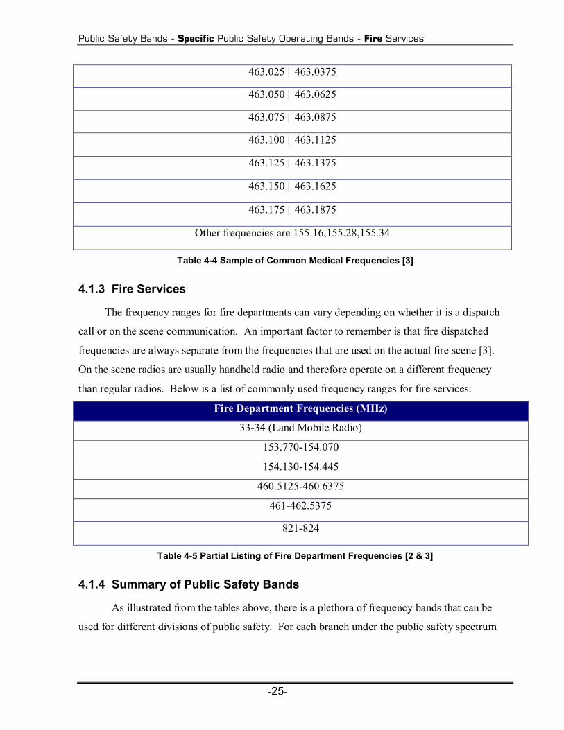
4.1.3 Fire Services
The frequency ranges for fire departments can vary depending on whether it is a dispatch
call or on the scene communication. An important factor to remember is that fire dispatched
frequencies are always separate from the frequencies that are used on the actual fire scene [3].
On the scene radios are usually handheld radio and therefore operate on a different frequency
than regular radios. Below is a list of commonly used frequency ranges for fire services:
Fire Department Frequencies (MHz)
33-34 (Land Mobile Radio)
153.770-154.070
154.130-154.445
460.5125-460.6375
461-462.5375
821-824
Table 4-5 Partial Listing of Fire Department Frequencies [2 & 3]
4.1.4 Summary of Public Safety Bands
As illustrated from the tables above, there is a plethora of frequency bands that can be
used for different divisions of public safety. For each branch under the public safety spectrum

Public Safety Bands - Virginia Tech Public Safety Bands
-26-
there is a certain range that is commonly used. Public safety services operate in 10 separate
bands, which has added capacity, but which has also caused the fragmentation that characterizes
the public safety spectrum today [6].
Public Safety Frequency Bands
Public Safety Branches Frequency Range ( MHz)
EMS 462.7375 470
150.05-155.6
Fire Service 154.01-154.445
461-462.5375
Law Enforcement 148-149.9
152.855-159.21
453.0125-460.5625
National Public Safety Planning ( Fire &
Police Radio)
821-824 (Mobile to Base)
866-869 (Base to Mobile)
Table 4-6 Public Safety Bands [2]
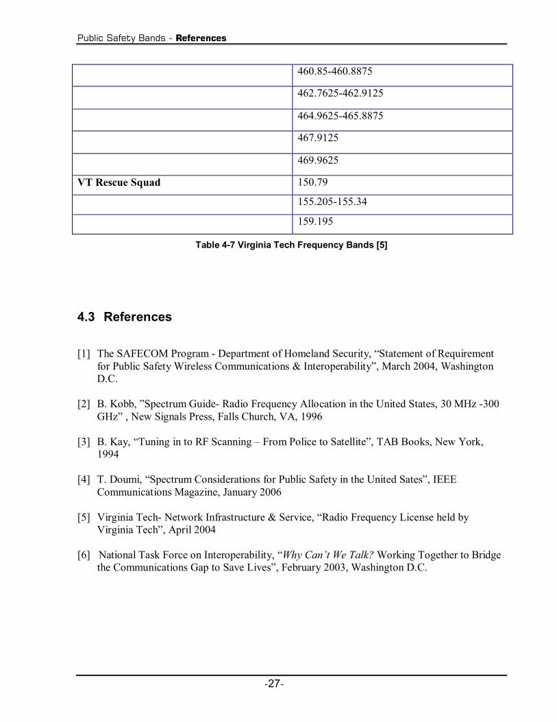
4.2 Virginia Tech Public Safety Bands
So far the public safety frequency bands that were discussed have been very broad and
covered a vast range. Each public safety jurisdiction has a set licences frequency that they are
allotted to communicate with. To give a more specific example of how the frequencies in the
public safety ranges are allocated, we will examine the radio licenses that are held by Virginia
Tech. Below is a table that illustrates the frequencies that can be used for the Virginia Tech
police department and rescue squad:
Virginia Tech Frequency Licenses
Division Frequency ( MHz)
VTPD 39.54
155.35-155.535
Public Safety Bands - References
-27-
460.85-460.8875
462.7625-462.9125
464.9625-465.8875
467.9125
469.9625
VT Rescue Squad 150.79
155.205-155.34
159.195
Table 4-7 Virginia Tech Frequency Bands [5]
4.3 References
[1] The SAFECOM Program - Department of Homeland Security, Statement of Requirement
for Public Safety Wireless Communications & Interoperability, March 2004, Washington D.C.
[2] B. Kobb, Spectrum Guide- Radio Frequency Allocation in the United States, 30 MHz -300
GHz , New Signals Press, Falls Church, VA, 1996 [3] B. Kay, Tuning in to RF Scanning From Police to Satellite, TAB Books, New York,
1994 [4] T. Doumi, Spectrum Considerations for Public Safety in the United Sates, IEEE
Communications Magazine, January 2006 [5] Virginia Tech- Network Infrastructure & Service, Radio Frequency License held by
Virginia Tech, April 2004 [6] National Task Force on Interoperability, Why Cant We Talk? Working Together to Bridge
the Communications Gap to Save Lives, February 2003, Washington D.C.

Characteristics of the SRH999 Quadband Antenna - Diamond Antenna SRH999 Quadband Antenna
-28-
5 Characteristics of the SRH999 Quadband Antenna
After surveying the available products, our research group selected the SRH999 Quadband
Antenna for use with our cognitive radio. There is little information available about the
performance characteristics of HT antennas; therefore we have to carry out detailed
measurements on the SRH999 antenna to understand how it will perform in our cognitive radio
application.
5.1 Diamond Antenna SRH999 Quadband Antenna
For this particular project, we need an antenna that has good performance in the common
public safety bands. The antenna that was purchased is an SRH999 Quadband HT Antenna, from
Diamond Antenna. It is advertised for use in these bands.
High quality, high gain HT antenna. Flexible whip with SMA.
Increase the performance on your handheld or wideband scanner
with a Diamond® SRH Series antenna.
Specifications:
Bands: 6m/2m/70cm/23cm
Watts: 10
Height: 19.5"
Connector: SMA
Remarks: Ideal for IC-T81A.
Figure 5-1 SRH999 Quadband HT Antenna [2]
Characteristics of the SRH999 Quadband Antenna - Antenna Measurement Setup
-29-
The SRH999 is a monopole whip antenna with an SMA connecter that offers about 3dB gain.
The 50 ohm antenna is rated to handle a power of 10 watts. The antenna is advertised to operate
in four different bands which correspond to approximately the following frequency ranges:
6m 50-54MHz
2m 148-150 MHz
70cm 430-450 MHz
23cm 1.2GHz
Table 5-1 Operating Bands of the SRH999 Antenna
According to the data sheets, the SRH999 operates as a 1/4 wave on 6 and 2 meters, a 1/2 wave
on 430 MHz and a 5/8 wave on 1.2 GHz. The antenna is optimized to receive and transmit at the
following bands: 150, 300, 450 and 900 MHz bands.
5.2 Antenna Measurement Setup
I took a wide variety of measurements in order to gather a good assessment of how the
antenna performed. The measurements involved measuring the S11 values of the antenna using a
network analyzer. S11 is the complex reflection coefficient at the antenna input port. The
measurement setup involved using two types of network analyzers and also measurement with
and without the presence of a ground plane. A ground plane is an electrically conductive surface
that serves as the near-field reflection point for an antenna, or as a reference ground in a circuit
[1]. A ground plane is utilized to limit the downward radiation of the antenna and to shield the
antenna radiation pattern from the distorting effects of nearby objects. The following sections
will illustrate the measurement procedures utilized for this particular analysis.

Characteristics of the SRH999 Quadband Antenna - Antenna Measurement Setup - Measurement 1: 50-500 MHz No Ground Plane
-30-
5.2.1 Measurement 1: 50-500 MHz No Ground Plane
The first measurement was taken using an 8751A HP Network Analyzer. This particular
network analyzer only has a sweep range from 5Hz-500 MHz; therefore this was the range over
which the measurement could be taken. The sweep incorporates a total of 801 points spanning
between the start and end frequencies.
Figure 5-2 1st Measurement: 50-500 MHZ; No Ground Plane
5.2.2 Measurement 2: 50 -1200 MHz No Ground Plane
This particular measurement incorporated a different type of network analyzer. The test
equipment that was used is an 8720C Network Analyzer, which spans from 50 MHz - 20 GHz
and includes 801 points. The upper bound of the span exceeds the value needed for this
particular project; therefore we stopped at 1200 MHz.

Characteristics of the SRH999 Quadband Antenna - Antenna Measurement Setup - Measurement 3: 50-2000MHz Circular Ground Plane
-31-
Figure 5-3 2nd Measurement Setup for 50-1200 MHZ with No Ground Plane
5.2.3 Measurement 3: 50-2000MHz Circular Ground Plane
The next measurement is the first that utilizes a ground plane. This particular
measurement utilizes that same network analyzer that was used in the second measurement, using
the same span a number of points. The first ground plane measured was a flat circular plate with
a diameter of 1.2446m. This dimension is over twice the length of the antenna to ensure an
effective ground plane.
Figure 5-4 3rd Measurement: 50-1200 MHZ; Circular Ground Plane

Characteristics of the SRH999 Quadband Antenna - Antenna Performance Characteristics
-32-
5.2.4 Measurement 4: 50-2000 MHz Metal Box Ground Plane
The next type of ground plane was a metal rectangular box, which is a model for a
handheld radio used by public safety personnel. This type of measurement will give us a more
accurate account of how the antenna will perform once it is integrated with the public safety CR.
Again the same network analyzer and frequency span is used in this measurement. The metal
box has a capacity of 0.17272m x 0.0254 m x 0.09652m.
Figure 5-5 4th t Measurement: 50-1200 MHZ; Metal Box Ground Plane
5.3 Antenna Performance Characteristics
5.3.1 Antenna Impedance Characteristics
The first performance metric that we will investigate is the input impedance
characteristics of the SRH999 quadband antenna. For single port devices (We are only
measuring one antenna.) the network analyzer needs only to measure the S11 characteristics.
Below is a sample representation of the data collected by the network analyzer:

Characteristics of the SRH999 Quadband Antenna - Antenna Performance Characteristics - Antenna Impedance Characteristics
-33-
Figure 5-6 Sample Representation of Network Analyzer Data
The sweep between the frequency ranges collects 801 points between the start and end frequency
values. We use the following equation to calculate impedance values.
"8751A REV5.01"
"CHANNEL: 1"
"MEASURE TYPE: S11"
"FORMAT TYPE: LIN MAG"
"NUMBER of POINTS: 801"
"SWEEP TIME: 321 ms"
"SWEEP TYPE: LIN FREQ"
"SOURCE POWER: 15 dBm"
"IF BANDWIDTH: 4 kHz"
"Frequency" "Data Real" "Data Imag"
5.00000000000E+07 7.513148E-01 -3.751057E-01
5.05625000000E+07 7.429105E-01 -3.862982E-01
5.11250000000E+07 7.258245E-01 -3.978730E-01
5.16875000000E+07 6.983957E-01 -4.052251E-01
5.22500000000E+07 6.628757E-01 -4.059341E-01
5.28125000000E+07 6.215913E-01 -3.967443E-01
5.33750000000E+07 5.750272E-01 -3.718169E-01
5.39375000000E+07 5.321384E-01 -3.224407E-01
5.45000000000E+07 5.173906E-01 -2.442817E-01
5.50625000000E+07 5.446764E-01 -1.631547E-01

Characteristics of the SRH999 Quadband Antenna - Antenna Performance Characteristics - Antenna Impedance Characteristics
-34-
ohmsZimpedanceantennaZ
whereZZZZS
L
L
L
50
,
0
0
011
==
+−=
(5-1)
Solving S11 for ZL:
11
110
11*
SSZZL
−+= (5-2)
This is the equation that will be used to find the impedance of the SRH999 antenna.
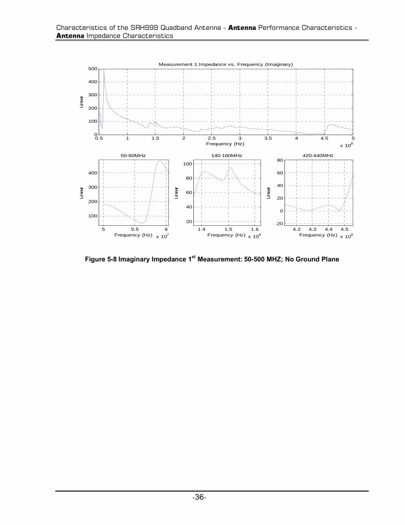
We will now analyze the real and imaginary components of the antenna impedance as recorded in
each of the four types of measurements that were taken. Each display will examine the overall
impedance over the entire frequency span and then focus on the actual frequency ranges for
which the antenna is advertised an in which our cognitive radio will operate. In each of the
figures, the real and imaginary components of the input impedance are shown for the entire
frequency sweep. The graphs also focus on an approximate range of which the antenna is
advertised to be designed.

Characteristics of the SRH999 Quadband Antenna - Antenna Performance Characteristics - Antenna Impedance Characteristics
-35-
Measurement 1: Real & Imaginary Components of Input Impedance:
0.5 1 1.5 2 2.5 3 3.5 4 4.5 5
x 108
-100
0
100
200
300
400
500
Frequency (Hz)
Line
ar
Measurement 1: Impedance vs. Frequency (Real)
5 5.5 6
x 107
100
200
300
400
Frequency (Hz)
Line
ar
50-60MHz
1.4 1.5 1.6
x 108
-10
0
10
20
30
40
50
60
Frequency (Hz)
Line
ar
140-160MHz
4.2 4.3 4.4 4.5
x 108
0
20
40
60
80
100
Frequency (Hz)Li
near
420-450MHz
Figure 5-7 Real Impedance 1st Measurement: 50-500 MHZ; No Ground Plane
Characteristics of the SRH999 Quadband Antenna - Antenna Performance Characteristics - Antenna Impedance Characteristics
-36-
0.5 1 1.5 2 2.5 3 3.5 4 4.5 5
x 108
0
100
200
300
400
500
Frequency (Hz)
Line
ar
Measurement 1:Impedance vs. Frequency (Imaginary)
5 5.5 6
x 107
100
200
300
400
Frequency (Hz)
Line
ar
50-60MHz
1.4 1.5 1.6
x 108
20
40
60
80
100
Frequency (Hz)
Line
ar
140-160MHz
4.2 4.3 4.4 4.5
x 108
-20
0
20
40
60
80
Frequency (Hz)
Line
ar
420-440MHz
Figure 5-8 Imaginary Impedance 1st Measurement: 50-500 MHZ; No Ground Plane

Characteristics of the SRH999 Quadband Antenna - Antenna Performance Characteristics - Antenna Impedance Characteristics
-37-
Measurement 2: Real & Imaginary Components of Input Impedance
0 0.2 0.4 0.6 0.8 1 1.2 1.4 1.6 1.8 2
x 109
0
100
200
300
400
Frequency (Hz)
Line
arMeasurement 2: Impedance vs. Frequency (Real)
5 5.5 6
x 107
50
100
150
200
250
Frequency (Hz)
Line
ar
50-60MHz
1.4 1.5 1.6
x 108
0
5
10
15
20
25
30
35
Frequency (Hz)
Line
ar140-160MHz
4.2 4.4
x 108
20
30
40
50
60
70
80
90
Frequency (Hz)
Line
ar
420-450MHz
1 1.2
x 109
0
50
100
150
200
Frequency (Hz)
Line
ar
900-1300MHz
Figure 5-9 Real Impedance 2nd Measurement: 50-1200 MHZ; No Ground Plane
0 0.2 0.4 0.6 0.8 1 1.2 1.4 1.6 1.8 2
x 109
0
100
200
300
400
500
Frequency (Hz)
Line
ar
Measurement 2:Impedance vs. Frequency (Imaginary)
5 5.5 6
x 107
100
150
200
250
300
350
400
450
Frequency (Hz)
Line
ar
50-60MHz
1.4 1.6
x 108
50
60
70
80
Frequency (Hz)
Line
ar
140-160MHz
4.2 4.4
x 108
10
20
30
40
50
60
Frequency (Hz)
Line
ar
420-450MHz
0.9 1 1.11.21.3
x 109
0
50
100
150
Frequency (Hz)
Line
ar
900-1300MHz
Figure 5-10 Imaginary Impedance 2nd Measurement: 50-1200 MHZ; No Ground Plane
Characteristics of the SRH999 Quadband Antenna - Antenna Performance Characteristics - Antenna Impedance Characteristics
-38-
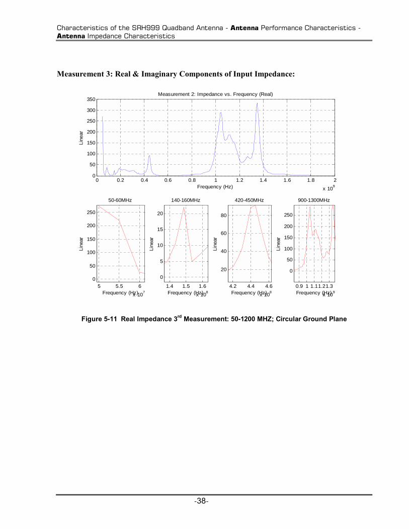
Measurement 3: Real & Imaginary Components of Input Impedance:
0 0.2 0.4 0.6 0.8 1 1.2 1.4 1.6 1.8 2
x 109
0
50
100
150
200
250
300
350
Frequency (Hz)
Line
ar
Measurement 2: Impedance vs. Frequency (Real)
5 5.5 6
x 107
0
50
100
150
200
250
Frequency (Hz)
Line
ar
50-60MHz
1.4 1.5 1.6
x 108
0
5
10
15
20
Frequency (Hz)
Line
ar
140-160MHz
4.2 4.4 4.6
x 108
20
40
60
80
Frequency (Hz)
Line
ar
420-450MHz
0.9 1 1.11.21.3
x 109
0
50
100
150
200
250
Frequency (Hz)
Line
ar
900-1300MHz
Figure 5-11 Real Impedance 3rd Measurement: 50-1200 MHZ; Circular Ground Plane

Characteristics of the SRH999 Quadband Antenna - Antenna Performance Characteristics - Antenna Impedance Characteristics
-39-
0 0.2 0.4 0.6 0.8 1 1.2 1.4 1.6 1.8 2
x 109
0
100
200
300
400
500
Frequency (Hz)
Line
ar
Measurement 3:Impedance vs. Frequency (Imaginary)
5 5.5 6
x 107
100
150
200
250
300
350
400
450
Frequency (Hz)
Line
ar
50-60MHz
1.4 1.5 1.6
x 108
50
60
70
80
Frequency (Hz)
Line
ar
140-160MHz
4.2 4.4
x 108
0
10
20
30
40
50
60
Frequency (Hz)
Line
ar
420-450MHz
1 1.2
x 109
0
50
100
150
200
Frequency (Hz)
Line
ar
900-1300MHz
Figure 5-12 Imaginary Impedance 3rd Measurement: 50-1200 MHZ; Circular Ground Plane

Characteristics of the SRH999 Quadband Antenna - Antenna Performance Characteristics - Antenna Impedance Characteristics
-40-
Measurement 4: Real & Imaginary Components of Input Impedance:
0 0.2 0.4 0.6 0.8 1 1.2 1.4 1.6 1.8 2
x 109
0
100
200
300
400
Frequency (Hz)
Line
arMeasurement 2: Impedance vs. Frequency (Real)
5 5.5 6
x 107
50
100
150
200
250
Frequency (Hz)
Line
ar
50-60MHz
1.4 1.5 1.6
x 108
0
5
10
15
20
25
30
35
Frequency (Hz)
Line
ar
140-160MHz
4.2 4.4
x 108
20
40
60
80
Frequency (Hz)
Line
ar
420-450MHz
1 1.2
x 109
0
50
100
150
200
Frequency (Hz)
Line
ar
900-1300MHz
Figure 5-13 Real Impedance 4th Measurement: 50-1200 MHZ; Metal Box Ground Plane
Characteristics of the SRH999 Quadband Antenna - Antenna Performance Characteristics - Antenna Impedance Characteristics
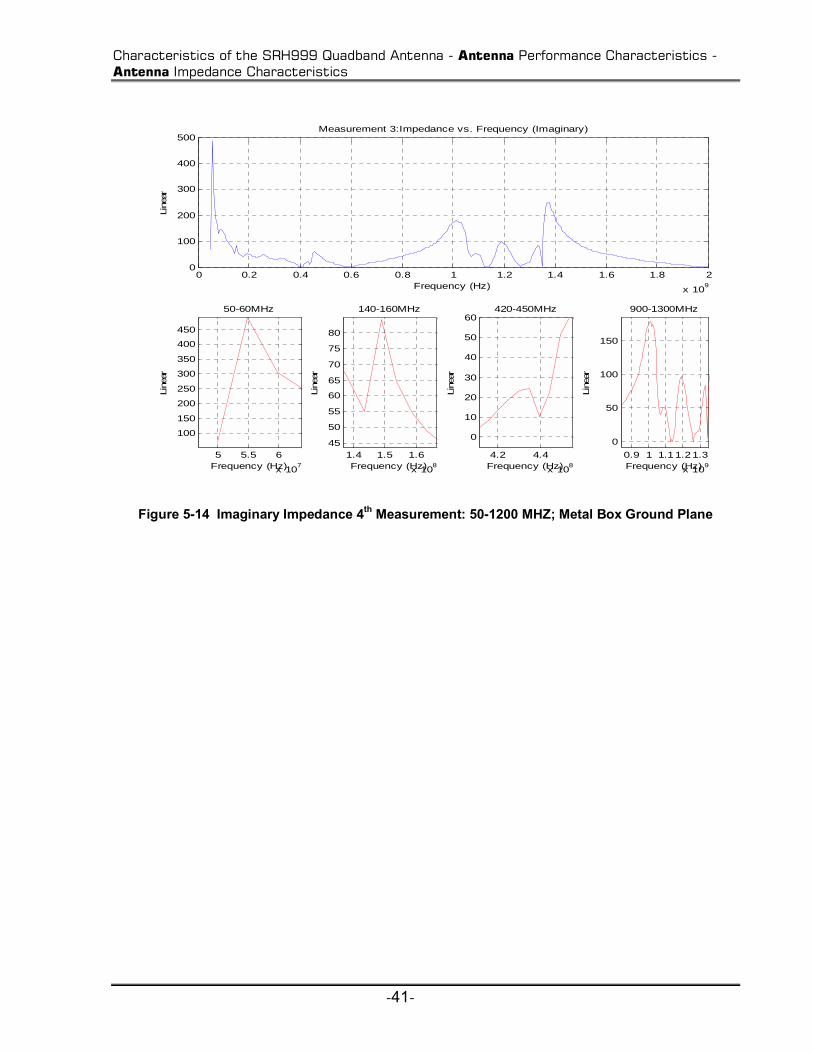
-41-
0 0.2 0.4 0.6 0.8 1 1.2 1.4 1.6 1.8 2
x 109
0
100
200
300
400
500
Frequency (Hz)
Line
ar
Measurement 3:Impedance vs. Frequency (Imaginary)
5 5.5 6
x 107
100
150
200
250
300
350
400
450
Frequency (Hz)
Line
ar
50-60MHz
1.4 1.5 1.6
x 108
45
50
55
60
65
70
75
80
Frequency (Hz)
Line
ar140-160MHz
4.2 4.4
x 108
0
10
20
30
40
50
60
Frequency (Hz)
Line
ar
420-450MHz
0.9 1 1.11.21.3
x 109
0
50
100
150
Frequency (Hz)
Line
ar
900-1300MHz
Figure 5-14 Imaginary Impedance 4th Measurement: 50-1200 MHZ; Metal Box Ground Plane
Characteristics of the SRH999 Quadband Antenna - Antenna Performance Characteristics - Antenna Impedance Characteristics
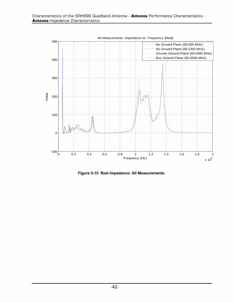
-42-
0 0.2 0.4 0.6 0.8 1 1.2 1.4 1.6 1.8 2
x 109
-100
0
100
200
300
400
500
Frequency (Hz)
Line
ar
All Measurments: Impedance vs. Frequency (Real)
No Ground Plane (50-500 MHz)
No Ground Plane (50-1200 MHz)
Circular Ground Plane (50-2000 MHz)
Box Ground Plane (50-2000 MHz)
Figure 5-15 Real Impedance: All Measurements
Characteristics of the SRH999 Quadband Antenna - Antenna Performance Characteristics - Antenna Impedance Characteristics
-43-
0 0.2 0.4 0.6 0.8 1 1.2 1.4 1.6 1.8 2
x 109
0
50
100
150
200
250
300
350
400
450
500
Frequency (Hz)
Line
ar
All Measurments: Impedance vs. Frequency (Imaginary)
No Ground Plane (50-500 MHz)
No Ground Plane (50-1200 MHz)
Circular Ground Plane (50-2000 MHz)
Box Ground Plane (50-2000 MHz)
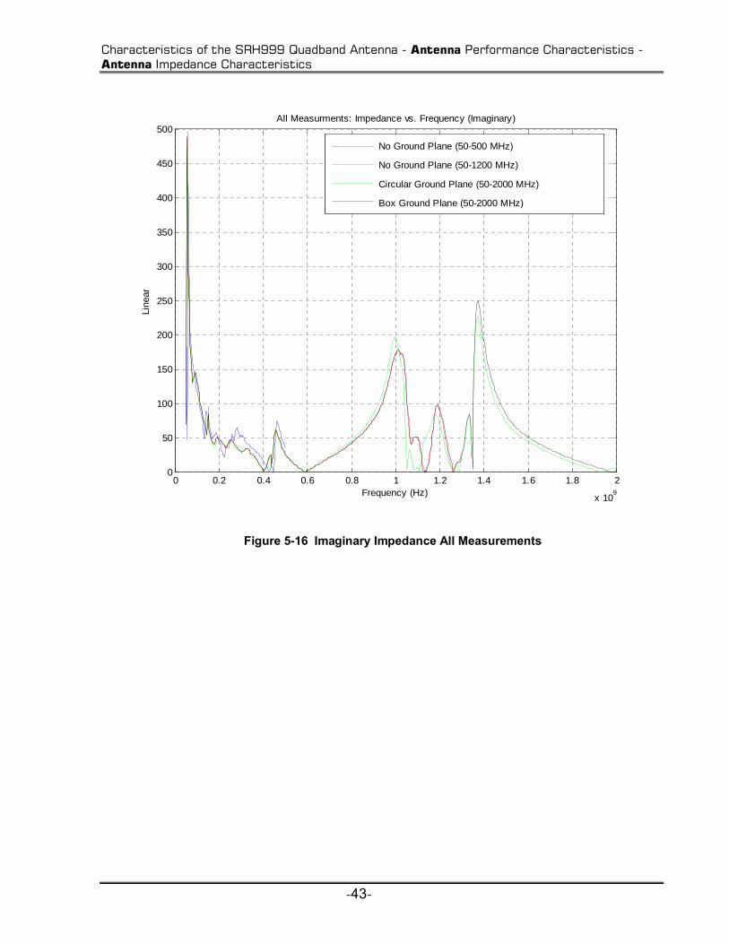
Figure 5-16 Imaginary Impedance All Measurements

Characteristics of the SRH999 Quadband Antenna - Antenna Performance Characteristics - Antenna Impedance Magnitude Characteristics
-44-
5.3.2 Antenna Impedance Magnitude Characteristics
The magnitude components of the impedance are given by the following equation:
Z real Z imag Z
whereZ total impedance
= +
=
( ) ( )
,
2 2
(5-3)
Measurement 1: Impedance Magnitude
0.5 1 1.5 2 2.5 3 3.5 4 4.5 5
x 108
0
100
200
300
400
500
600
Frequency (Hz)
Mag
nitu
de
Measurement 1:Impedance vs. Frequency (Magnitdue)
5 5.5 6
x 107
200
300
400
500
Frequency (Hz)
Line
ar
50-60MHz
1.4 1.5 1.6
x 108
30
40
50
60
70
80
90
100
Frequency (Hz)
Line
ar
140-160MHz
4.2 4.3 4.4 4.5
x 108
20
40
60
80
100
Frequency (Hz)
Line
ar
420-440MHz
Figure 5-17 Magnitude Impedance 1st Measurement: 50-500 MHZ; No Ground Plane

Characteristics of the SRH999 Quadband Antenna - Antenna Performance Characteristics - Antenna Impedance Magnitude Characteristics
-45-
Measurement 2: Impedance Magnitude
0 0.2 0.4 0.6 0.8 1 1.2 1.4 1.6 1.8 2
x 109
0
100
200
300
400
500
600
Frequency (Hz)
Mag
nitu
de
Measurement 2:Impedance vs. Frequency (Magnitdue)
5 5.5 6
x 107
200
250
300
350
400
450
500
Frequency (Hz)
Line
ar
50-60MHz
1.4 1.5 1.6
x 108
50
60
70
80
90
Frequency (Hz)
Line
ar
140-160MHz
4.2 4.4
x 108
20
30
40
50
60
70
80
90
Frequency (Hz)
Line
ar
420-450MHz
1 1.2
x 109
-50
0
50
100
150
200
250
Frequency (Hz)
Line
ar
900-1300MHz
Figure 5-18 Magnitude Impedance 2nd Measurement: 50-1200 MHZ; No Ground Plane

Characteristics of the SRH999 Quadband Antenna - Antenna Performance Characteristics - Antenna Impedance Magnitude Characteristics
-46-
Measurement 3: Impedance Magnitude
0 0.2 0.4 0.6 0.8 1 1.2 1.4 1.6 1.8 2
x 109
0
100
200
300
400
500
600
Frequency (Hz)
Mag
nitu
de
Measurement 3:Impedance vs. Frequency (Magnitdue)
5 5.5 6
x 107
300
350
400
450
500
Frequency (Hz)
Line
ar
50-60MHz
1.4 1.5 1.6
x 108
40
50
60
70
80
90
Frequency (Hz)
Line
ar
140-160MHz
4.2 4.4
x 108
20
30
40
50
60
70
80
90
Frequency (Hz)
Line
ar
420-450MHz
1 1.2
x 109
0
50
100
150
200
250
300
Frequency (Hz)Li
near
900-1300MHz
Figure 5-19 Magnitude Impedance 3rd Measurement: 50-1200 MHZ; Circular Ground Plane

Characteristics of the SRH999 Quadband Antenna - Antenna Performance Characteristics - Antenna Impedance Magnitude Characteristics
-47-
Measurement 4: Impedance Magnitude
0 0.2 0.4 0.6 0.8 1 1.2 1.4 1.6 1.8 2
x 109
0
100
200
300
400
500
600
Frequency (Hz)
Mag
nitu
de
Measurement 3:Impedance vs. Frequency (Magnitdue)
5 5.5 6
x 107
250
300
350
400
450
500
Frequency (Hz)
Line
ar
50-60MHz
1.4 1.5 1.6
x 108
50
60
70
80
90
Frequency (Hz)
Line
ar
140-160MHz
4.2 4.4
x 108
20
30
40
50
60
70
80
90
Frequency (Hz)
Line
ar
420-450MHz
1 1.2
x 109
-50
0
50
100
150
200
250
Frequency (Hz)
Line
ar
900-1300MHz
Figure 5-20 Magnitude Impedance 4th Measurement: 50-1200 MHZ; Metal Box Ground Plane

Characteristics of the SRH999 Quadband Antenna - Antenna Performance Characteristics - Antenna Impedance Magnitude Characteristics
-48-
0 0.2 0.4 0.6 0.8 1 1.2 1.4 1.6 1.8 2
x 109
0
100
200
300
400
500
600
Frequency (Hz)
Mag
nitu
de
All Measurments: Impedance vs. Frequency (Magnitude)
No Ground Plane (50-500 MHz)
No Ground Plane (50-1200 MHz)
Circular Ground Plane (50-2000 MHz)
Box Ground Plane (50-2000 MHz)
Figure 5-21 Impedance Magnitude All Measurements
From the impedance plots, it can be shown that overall the antenna demonstrates good
impedance performance in the designated antenna ranges of the antenna. There is a good
agreement between all four antenna measurements that were taken. At the upper and lower band
ranges there is a dramatic peak in the impedance values. From the graphs at the 50MHz range
and 1.2 GHz range the impedance is extremely high, which indicates a severe mismatch. The
antenna displays relatively good impedance performance in the designated operating bands. For
most antennas optimal performance is achieved when the impedance values are around 50ohms,
but in general the real part of the impedance should be approximately between 35-75 ohms. The
SRH999 impedance plot demonstrates that in the desired ranges the impedance is around these

Characteristics of the SRH999 Quadband Antenna - Antenna Performance Characteristics - Antenna VSWR Characteristics
-49-
particular values, from the real impedance figure. This is also a good indication that the antenna
will have satisfactory performance in most of our desired public safety bands.
5.3.3 Antenna VSWR Characteristics
The next category that we will consider is the VSWR characteristics of the antenna.
The same measurements were utilized from the network analyzer, except that the equation is
modified to find the VSWR values for the antenna:
11
11
11
SS
VSWR−+
= (5-4)
For reasonably good performance the VSWR should be 2 or less.
Measurement 1: VSWR
0.5 1 1.5 2 2.5 3 3.5 4 4.5 5
x 108
0
2
4
6
8
10
Frequency (Hz)
Line
ar
Measurement 1: VSWR vs. Frequency
5 5.5 6
x 107
3.6
3.7
3.8
3.9
4
4.1
Frequency (Hz)
Line
ar
50-60MHz
1.4 1.5 1.6
x 108
3
3.2
3.4
3.6
3.8
Frequency (Hz)
Line
ar
140-160MHz
4.2 4.4 4.6 4.8
x 108
1
1.5
2
2.5
3
3.5
Frequency (Hz)
Line
ar
420-440MHz
Figure 5-22 VSWR 1st Measurement: 50-500 MHZ; No Ground Plane

Characteristics of the SRH999 Quadband Antenna - Antenna Performance Characteristics - Antenna VSWR Characteristics
-50-
Measurement 2: VSWR
0 2 4 6 8 10 12 14
x 108
0
2
4
6
8
10
Frequency (Hz)
Line
ar
Measurement 2: VSWR vs. Frequency
5 5.5 6
x 107
5
6
7
8
9
10
Frequency (Hz)
Line
ar
50-60MHz
1.5 2
x 108
3
3.2
3.4
3.6
3.8
Frequency (Hz)
Line
ar
140-160MHz
4 4.24.44.64.8
x 108
1.5
2
2.5
3
3.5
Frequency (Hz)
Line
ar
420-450MHz
1 1.5
x 109
1.5
2
2.5
3
3.5
4
Frequency (Hz)Li
near
900-1300MHz
Figure 5-23 VSWR 2nd Measurement: 50-1200 MHZ; No Ground Plane
Measurement 3: VSWR

Characteristics of the SRH999 Quadband Antenna - Antenna Performance Characteristics - Antenna VSWR Characteristics
-51-
0 2 4 6 8 10 12 14
x 108
0
2
4
6
8
10
Frequency (Hz)
Line
ar
Measurement 3: VSWR vs. Frequency
5 6
x 107
6
7
8
9
10
Frequency (Hz)
Line
ar
50-60MHz
1.5 2
x 108
2.8
3
3.2
3.4
3.6
3.8
Frequency (Hz)
Line
ar
140-160MHz
4 4.5
x 108
1.5
2
2.5
3
3.5
Frequency (Hz)
Line
ar
420-450MHz
1 1.5
x 109
1
1.5
2
2.5
3
3.5
Frequency (Hz)Li
near
900-1300MHz
Figure 5-24 VSWR 3rd Measurement: 50-1200 MHZ; Circular Ground Plane

Characteristics of the SRH999 Quadband Antenna - Antenna Performance Characteristics - Antenna VSWR Characteristics
-52-
Measurement 4: VSWR
0 2 4 6 8 10 12 14
x 108
0
2
4
6
8
10
Frequency (Hz)
Line
arMeasurement 4: VSWR vs. Frequency
5 5.5 6 6.5
x 107
5
6
7
8
9
10
Frequency (Hz)
Line
ar
50-60MHz
1.41.61.8 2 2.2
x 108
2
2.5
3
3.5
4
Frequency (Hz)
Line
ar
140-160MHz
4 4.5 5
x 108
1.5
2
2.5
3
3.5
4
Frequency (Hz)
Line
ar
420-450MHz
1 1.2
x 109
1.5
2
2.5
3
3.5
Frequency (Hz)Li
near
900-1300MHz
Figure 5-25 VSWR 4th Measurement: 50-1200 MHZ; Metal Box Ground Plane

Characteristics of the SRH999 Quadband Antenna - Antenna Performance Characteristics - Antenna Power Characteristics
-53-
0 2 4 6 8 10 12 14
x 108
0
0.5
1
1.5
2
2.5
3
3.5
4
Frequency (Hz)
Line
arAll Measurements : VSWR vs. Frequency
No Ground Plane (50-500 MHz)
No Ground Plane (50-1200 MHz)Circular Ground Plane (50-2000 MHz)
Box Ground Plane (50-2000 MHz)
Figure 5-26 VSWR All Measurements
The VSWR graphs indicate that the antenna has relatively high values for the VSWR.
This indicates that the antenna has only tolerable impedance matching. In the most of the bands
of interest the VSWR falls in the range between the values of 0.5 to 4. The average value of
VSWR for the antenna falls around the range of 2.0 to 3.5. The VSWR characteristics seem to be
similar for each measurement.
5.3.4 Antenna Power Characteristics
A simple test was conducted in order to see how well the SRH999 antennas perform in
transmit and receive scenarios and to observe the losses associated with the antennas. The first

Characteristics of the SRH999 Quadband Antenna - Antenna Performance Characteristics - Antenna Power Characteristics
-54-
antenna was attached to a MG3700A signal generator, which sent out an FM signal. The FM
waveform that was created in MATLAB had an SNR of 100dB, a sampling rate of 20 kHz, and a
deviation of 2000 Hz. The power level of the signal generator was set to 0dBm for this particular
test. For the receive side, the second antenna was attached to a MS2781A spectrum analyzer to
observe the signal that was being transmitted. The antennas were approximately 2m apart during
the test. We note that this is in the near field, and that Multipath effects may also be severe. The
frequencies were selected for operation in the desired bands where the antennas should have
optimal performance. Below are the results from varying the frequencies:
Received Power
Frequency (MHz) Power (dBm)
50 -37
150 -70
300 -38
430 -45
900 -75
1200 -63
Table 5-2 Measured Received Power between Tx/Rx
At the 50 MHz range the best received power was shown to be around -37dBm. Overall
the results show in general that as frequency increases the power received decreases. As
expected the receive power values are relatively low due to the fact that since the antennas are
oriented close together you can not account for multipath affects between the transmit and
receive antennas. For these particular measurements we will have to take in account the
dependence of path loss on frequency, which is given by: )(log20 10 f , where f equals
frequency. The received power measurements indicate that the SRH999 antenna operates
reasonably well in a rich multipath environment where the public safety cognitive radio could
potentially be used.

Characteristics of the SRH999 Quadband Antenna - References
-55-
5.4 References
[1] Wikipedia, Ground plane , http://en.wikipedia.org/wiki/Ground_plane, 2001.
[2] Diamond Antennas, SRH999 Quadband HT Antenna,
http://www.rfparts.com/diamond/srh999.html.

Effects of the Antenna Characteristics on Public Safety CR - System Components - GNU Radio
-56-
6 Effects of the Antenna Characteristics on Public Safety CR
In this chapter we will investigate the interaction between the antenna and the radio. This
interaction is crucial to system performance. The essential factors that we will examine include:
the antennas performance characteristics; effects of the antenna impedance on the transmitter
output circuit; the relative radiated power; and the angle of maximum radiation. These factors
should establish a reasonably clear picture representation of the affects of the antenna hardware
on the public safety CR system.
6.1 System Components
6.1.1 GNU Radio
The cognitive engine will control the GNU radio software defined radio platform. A GNU
radio is a set of software signal processing building blocks that allow users to create their own
software defined radio [3]. Below is a typical software defined radio block diagram:

Effects of the Antenna Characteristics on Public Safety CR - System Components - GNU Radio
-57-
Figure 6-1 Typical SR Block Diagram [3]
Figure 6-1 indicates that in the section label Your Code Here! is where the GNU radio code is
implemented in the software radio setup. The analog parts of the transmitter and receiver, the
ADCs and DACs, and the software that runs the GNU code are included in the Universal
Software Radio Peripheral (USRP). The USRP enables individuals to rapidly design and
implement powerful, flexible software defined radio systems, which makes up the hardware
solution for the SDR. The USRP can simultaneously transmit and receive two separate complex
(or four real) RF signals in real time [2].

Effects of the Antenna Characteristics on Public Safety CR - Experiment Architecture
-58-
Figure 6-2 USRP Circuit Board and Block Diagram [2]
6.2 Experiment Architecture
In order to estimate the effects that the antenna will have on the cognitive radio system it is
essential to observe various characteristics in order to understand the behavioural influence of the
antenna hardware. The objective is to analyze the antenna characteristics and subsequently
utilize the data to process how it will affect the potential public safety cognitive radio which is
being developed through the use of a GNU radio and USRP. Below is a schematic of the
transmitter output circuitry on the Basic Tx Daughterboard of the USRP:

Effects of the Antenna Characteristics on Public Safety CR - Experiment Architecture
-59-
Figure 6-3 Portion of USRP Transmitter Output Circuitry [2]
On the transmit side J48 represents the location of the SMA connector for the antenna. The two
RC parallel circuits are connected to the output terminals of the Programmable Gain Amplifier
(PGA) chips, which is represented by IOUTP_A and IOUTN_A. Within the RC parallel circuit,
the resistor is utilized to convert current to voltage and the capacitor serves as a filter.
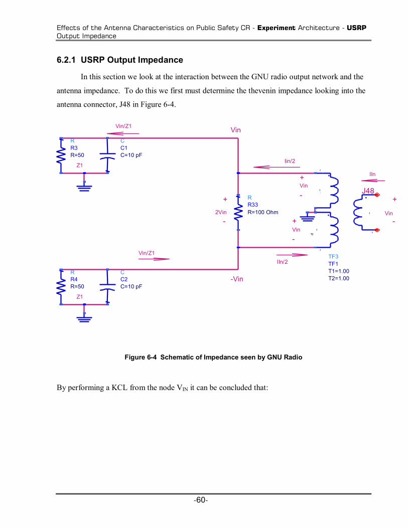
Effects of the Antenna Characteristics on Public Safety CR - Experiment Architecture - USRP Output Impedance
-60-
6.2.1 USRP Output Impedance
In this section we look at the interaction between the GNU radio output network and the
antenna impedance. To do this we first must determine the thevenin impedance looking into the
antenna connector, J48 in Figure 6-4.
Figure 6-4 Schematic of Impedance seen by GNU Radio
By performing a KCL from the node VIN it can be concluded that:
J48
Vin
IIn
-Vin
Vin
-
+Vin
+
-Vin
-
++
-2Vin
Vin/Z1
Vin/Z1 IIn/2
Iin/2
Z1
Z1
RR33R=100 Ohm
TF3TF1
T2=1.00T1=1.00
1
2
3
3
1-
1 T2
1
RR3 R=50
CC1 C=10 pF
RR4 R=50
CC2 C=10 pF

Effects of the Antenna Characteristics on Public Safety CR - Experiment Architecture - USRP Output Impedance
-61-
3342
13342
332
2
1
1
1
RZI
VZ
RZVI
RV
ZVI
IN
ININ
ININ
INININ
+==
+=
+=
(6-1)
Substituting in numerical values, we can now display the source impedance of the GNU radio
transmitter versus frequency.
0 5 10 15
x 108
2
4
6
8
10
12
14
Frequency (Hz)
Line
ar
Output Impedance Check ( Zin) (Real)
0 5 10 15
x 108
0
1
2
3
4
5
6
7
Frequency (Hz)
Line
ar
Output Impedance Check ( Zin) (Imaginary)
0 2 4 6 8 10 12 14
x 108
4
6
8
10
12
14
Frequency (Hz)
Mag
nitu
de
Output Impedance Check ( Zin)
Figure 6-5 Real, Imaginary, Magnitude vs. Frequency of Impedance Presented by GNU Radio

Effects of the Antenna Characteristics on Public Safety CR - Experiment Architecture - Relative Radiated Power
-62-
These graphs indicate that the GNU radio output impedance is fairly low and varies slowly with
frequency. We would therefore expect the GNU radio to behave reasonably like a voltage source
and be relatively insensitive to variations in antenna impedance.
6.2.2 Relative Radiated Power
The interaction between the antenna impedance Za and the GNU radio source impedance
Zin determines the relative power radiated by the antenna. Figure 6-7 is a schematic used to
determine the radiated power for the cognitive radio system. Obviously, maximum power would
be radiated if Za = Zin*.
I
Vt=1
-
+Zin
Za
Figure 6-6 Schematic for Determining Radiated Power
From Figure 6-7 Zin represents the GNU radio impedance and Za represent the antenna
impedance. To compute the radiated power we use the following equations:

Effects of the Antenna Characteristics on Public Safety CR - Experiment Architecture - Relative Radiated Power
-63-
[ ]
=
=+
=
MAX
RADRAD
ARAD
Ain
T
PPR
ZIPZZ
VI
log10
Re*2
(6-2)
RRAD represents the relative radiated power in dB. PMAX is determined by selecting the highest
value from the output of PRAD. Note that it is a somewhat artificial concept in that its numerical
value may exceed the maximum output power of the GNU radio USRP. It simply serves as a
basis for comparing the output power values that the antenna and GNU radio transmitter would
radiate at different frequencies. The relative radiated power was computed for each of the four
types of measurements to see if there would be a consistency in the values of the measurements.

Effects of the Antenna Characteristics on Public Safety CR - Experiment Architecture - Relative Radiated Power
-64-
0 0.2 0.4 0.6 0.8 1 1.2 1.4 1.6 1.8 2
x 109
-45
-40
-35
-30
-25
-20
-15
-10
-5
0
Frequency (Hz)
Pra
d (d
B)
All Measurments: Relative radiated Power
No Ground Plane (50-500 MHz)No Ground Plane (50-1200 MHz)Circular Ground Plane (50-2000 MHz)Box Ground Plane (50-2000 MHz)
Figure 6-7 Radiated Power All Measurements
The conclusion after comparing the measured radiated power for the different measurement
setups, respectively, is that there is not a high correlation in the results. The estimation of the
radiated power appears to be steady except for the places where the antenna experiences severe
impedance mismatch which cause degradation in the performance. The use of a ground plane
show more effective radiated power at higher frequencies. The relative radiated power results
here have a better outcome compared to the received power measurements that were shown in
Table 5-2. Ideally the measurements should have some correlation between each other, but due
to adverse multipath affects that occurred when conducting the received power test, the system
performance is degraded.

Effects of the Antenna Characteristics on Public Safety CR - Experiment Architecture - Relative Radiated Power
-65-
-20
-18
-16
-14
-12
-10
-8
-6
-4
-2
0
1st Meas 2nd Meas 3rd Meas 4th Meas
Rad
iate
d po
wer
(dB
)
50 MHz149 MHz430 MHz1.2 GHz
Figure 6-8 Radiated Power for Test Measurements
Measurement Type Maximum Radiated Power (dBm)
1st Measurement: 50-500 MHZ; No
Ground Plane
13.76
2nd Measurement: 50-1200 MHZ; No Ground Plane
20.04
3rd Measurement: 50-1200 MHZ; 23.21

Effects of the Antenna Characteristics on Public Safety CR - Experiment Architecture - Angle of Maximum Radiation
-66-
Circular Ground Plane
4th Measurement: 50-1200 MHZ; Metal
Box Ground Plane
21.14
Table 6-1 Maximum Radiated Power
From Figure 6-8, we can see that the radiated power stays within a 10 dB range in all the
bands of interest under a variety of different measurement conditions. Table 6-1 shows the
outcome from the maximum radiated power that was calculated for each measurement setup.
The resulting values could have rendered better results, but are still in a range to help achieve
optimal performance. The maximum radiates power values that may also be beyond the
capability of the GNU radio transmitter.
6.2.3 Angle of Maximum Radiation
Angle of maximum radiation is an important aspect for antenna characteristics in
determining the maximum radiation direction for a particular antenna. The value of the
maximum angle can change for a variety of reasons. Usually in most scenarios the radiation
angle is always higher than the elevation angle as long as there are ground effects [4]. For typical
linear antenna the angle of maximum radiation can be found by observing the far-field pattern of
the antenna. For each far-field pattern the space pattern is a figure of revolution of pattern shown
around the axis of the antenna [1]. The far-field at a full wavelength has more of a directional
pattern than typical antennas. In order to obtain the value for the angle of maximum radiation for
our antenna we will utilize a set of standard equations to estimate the angular dependence of the
far-field [1]:

Effects of the Antenna Characteristics on Public Safety CR - Experiment Architecture - Angle of Maximum Radiation
-67-
oo tomL
GHztoMHzfwhere
LLE
fc
9009906.0
2.150,
sin)2/cos()2/)coscos((
2
===
−=
=
=
θ
θβθβ
λπβ
λ
(6-3)
For the equations the frequency is varied from 50MHz to 1.2GHz, the maximum value of E is
found, and the corresponding value of θ is θmax. Ideally the radiation angle would be toward the
horizontal when the antenna is held vertical as it would be on a handset. Therefore we take 90
minus θmax to obtain the angle of maximum radiation, which is the angle above the horizontal.
Figure 6-9 Defining Theta
Figure 6-10 shows the angle of maximum radiation for the frequency range:

Effects of the Antenna Characteristics on Public Safety CR - Experiment Architecture - Angle of Maximum Radiation
-68-
Figure 6-10 Angle of Maximum Radiation
Figure 6-11 shows the angle of maximum radiation direction as a function of frequency. The
angle of maximum radiation direction remains at 0° from 50 MHz to about 430 MHz. After this
point the max angle shifts upward. As the frequency goes up and the antenna gets longer in terms
of wavelength and the direction of maximum radiation moves upward toward the end of the
antenna. This phenomenon is typical for short antenna radiation that is perpendicular to the
antennas axis. An infinitely long antenna would radiate in the direction of its axis.
0 2 4 6 8 10 12
x 108
0
10
20
30
40
50
60
70
Frequency (Hz)
Ang
le A
bove
Hor
izon
tal
Angle of Max Radiation

Effects of the Antenna Characteristics on Public Safety CR - Evaluation of Antenna Affects - Implementing Antenna Hardware with GNU Radio
-69-
6.3 Evaluation of Antenna Affects
6.3.1 Implementing Antenna Hardware with GNU Radio
A test scenario was implemented to test whether incorporating the antenna hardware with
the USRP and GNU radio would affect the performance of the system. The test involves
attaching the SRH999 to the USRP daughterboard.
Figure 6-11 Antenna Hardware with USRP
Once the hardware is in place an FM audio signal at approximately 100 MHz is then transmitted
from the GNU radio. Using a conventional radio we were able to obtain reception on the radio
and hear the audio being sent. We also performed the test without the antenna and could not find
the signal. Clearly the antenna works.

Effects of the Antenna Characteristics on Public Safety CR - References
-70-
Figure 6-12 Antenna Hardware Test Setup
Above is the test scenario which shows the USRP with the antenna hardware and the radio that
was used to receive the transmitted audio. The components are approximately 2 meters away
from each other. Another test was performed in order to see the maximum distance the signal
could be transmitted. The maximum distance that the radio was still able to clearly receive the
signal was around 10 meters. This limitation is a consequence of the low power of the USRP
transmitter and the difficult indoor propagation environment.
6.4 References
[1] J. Kraus, Antennas. New York: McGraw-Hill Book Company, 1950.
[2] Ettus Research, Universal Software defined radio Peripheral (USRP) ,

Effects of the Antenna Characteristics on Public Safety CR - References
-71-
http://www.ettus.com/custom.html
[3] GNU Radio - The GNU Software defined radio, Exploring GNU Radio,
http://www.gnu.org/software/gnuradio/doc/exploring-gnuradio.html, November 29, 2004.
[4] J. Cunningham, The Complete Broadcast Antenna Handbook- Design, Installation,
Operation & Maintenance. Blue Ridge Summit, PA.: TAB Books, 1977. [5] J.D. Jraus, Antennas, in McGraw-Hill Electrical & Electronic Engineering Series, New
York: McGraw-Hill Book Company, Inc., 1950

CONCLUSIONS
-72-
7 CONCLUSIONS
In this thesis I have investigated the factors that influence antenna selection for a public
safety cognitive radio and reported on the properties of the SRH999 antenna that was selected.
While the impedance of the SRH999 varies significantly with frequency, it is relatively
insensitive to the presence or absence of a ground plane or to the construction of the ground plane
that is used. The antenna presents a reasonable match to a 50 ohm line, with an average VSWR
of about 2.3 in the public safety frequency bands. Variations with frequency of the antenna
impedance and the transmitter source impedance will cause transmitted power to fluctuate over a
range of about ±10 dB from nominal, but this will be relatively insignificant in comparison with
multipath effects and variations in path loss under operational conditions.
This antenna is a good choice for a public safety cognitive radio because it performs well in
the public safety bands of interest. When incorporated with the GNU radio transmitter it does not
degrade performance and is very lightweight and somewhat flexible, which will not add any
undue weight to the top of the mobile radio. Its undesirable features are that the antenna does not
perform well outside of the public safety bands and performance of the antenna is slightly
degraded at short ranges (i.e. 2m).
For future recommendations or work, tests should be conducted using a number of different
commonly used public safety antennas. Another recommendation would be to test the antennas
in scenarios where they will be utilized to get a better understanding of how the system will
perform.

VITA
-73-
VITA
Akilah L. Hugine was born on September 17, 1982 in Orangeburg, SC. She received her
Bachelor of Science Degree in Electrical Engineering from North Carolina A&T State University
in May 2004. In the Fall of 2004 she enrolled in the Bradley Department of Electrical and
Computer Engineering at Virginia Polytechnic Institute and State University to pursue a Masters
degree. She joined Dr. Charles Bostian and his Center for Wireless Telecommunications
research group and has since been involved in research related to cognitive radio. She is
currently in the process of completing the requirements for the M.S. Degree in Electrical
Engineering at the Virginia Polytechnic Institute and State University.