Embed Size (px)
Citation preview
Antenna? What’s That?
Chet Thayer
WA3I
Space: The Final Frontier
• Empty Space (-Time)
– Four dimensional region that holds
“everything”
– Is “Permeable”: It requires energy to set up a
magnetic field within it.
– An oscillating magnetic field dissipates
energy, i.e. “radiates”
– Light propagates through it.
Magnetic Field
• Relativistic force created by an electric
current
• An oscillating electric current creates an
oscillating electric and magnetic field
• Under the right conditions, an oscillating
electric current will “radiate”
electromagnetic energy
Light – Electromagnetic
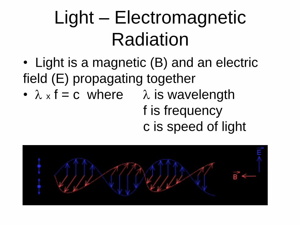
Radiation • Light is a magnetic (B) and an electric
field (E) propagating together
• l x f = c where l is wavelength
f is frequency
c is speed of light
Antenna
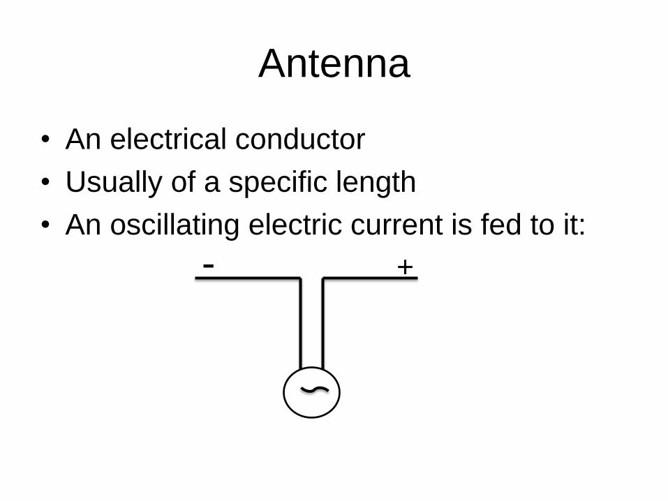
• An electrical conductor
• Usually of a specific length
• An oscillating electric current is fed to it:
- +
Resonant Antenna
• If the conductor is ½ a wavelength long,
the current will resonate
• Like a water sloshing in a trough, the
electric current will flow back and forth
along the conductor in synchrony with the
applied electric current.
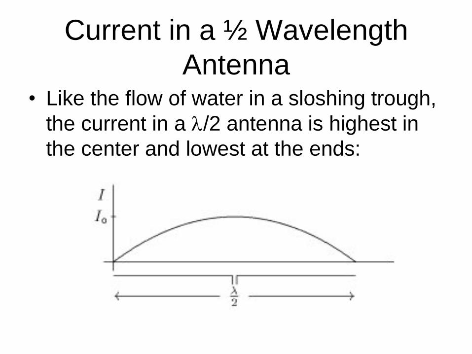
Current in a ½ Wavelength
Antenna • Like the flow of water in a sloshing trough,
the current in a l/2 antenna is highest in
the center and lowest at the ends:
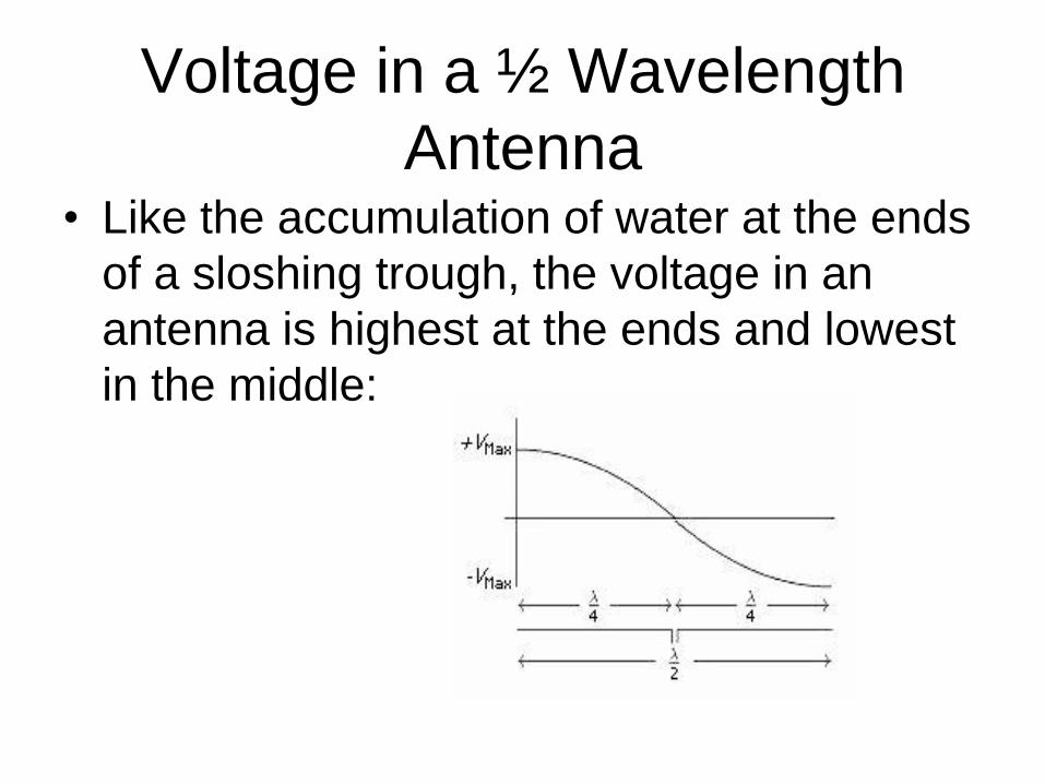
Voltage in a ½ Wavelength
Antenna • Like the accumulation of water at the ends
of a sloshing trough, the voltage in an
antenna is highest at the ends and lowest
in the middle:
Voltage on the Antenna
• Measured voltage between any point on
the antenna and “ground” will vary
sinusoidally
• Measured current at any point in the
antenna will also vary sinusoidally
What is Ground?
• Ground is an object large enough to
absorb a reasonable amount of electrical
charge and not become measurably
charged itself. For example: the Earth.
• DC Ground has low resistance to the
Earth.
• AC (or RF) Ground has low impedance
(both inductive and capacitive) to the
Earth.
Grounded?
• Anything connected by a low resistance
conductor to a ground rod will be at DC
ground.
• However, a length of wire will have
inductive reactance. To be an AC (RF)
ground, the wire should be less than 5% of
a wavelength.
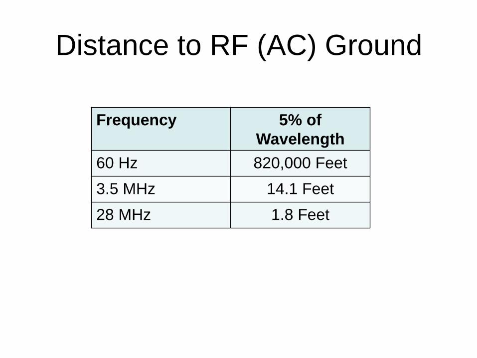
Distance to RF (AC) Ground
Frequency 5% of
Wavelength
60 Hz 820,000 Feet
3.5 MHz 14.1 Feet
28 MHz 1.8 Feet
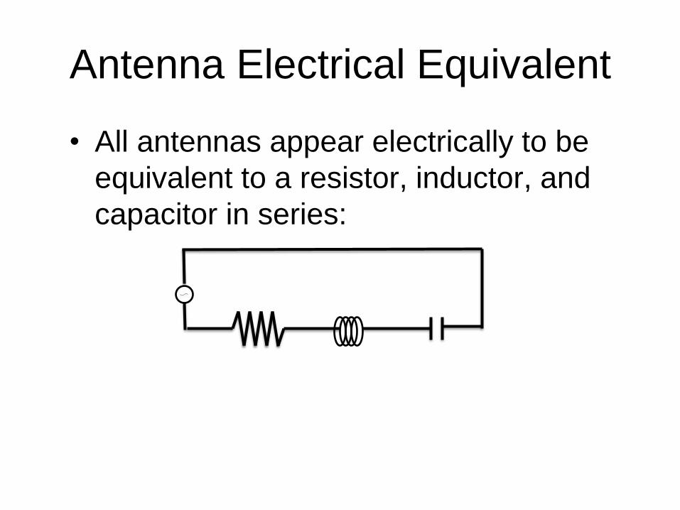
Antenna Electrical Equivalent
• All antennas appear electrically to be
equivalent to a resistor, inductor, and
capacitor in series:
Antenna Electrical
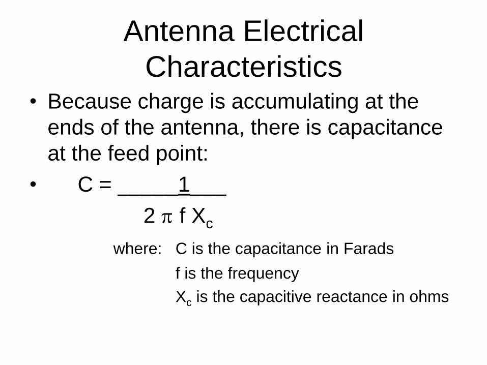
Characteristics • Because charge is accumulating at the
ends of the antenna, there is capacitance
at the feed point:
• C = _____1___
2 p f Xc
where: C is the capacitance in Farads
f is the frequency
Xc is the capacitive reactance in ohms
Antenna Electrical
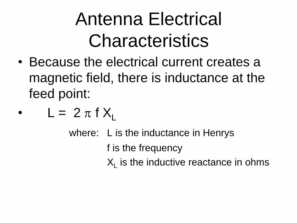
Characteristics • Because the electrical current creates a
magnetic field, there is inductance at the
feed point:
• L = 2 p f XL
where: L is the inductance in Henrys
f is the frequency
XL is the inductive reactance in ohms
Antenna Electrical
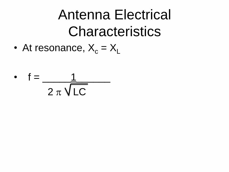
Characteristics • At resonance, Xc = XL
• f = _____1______
2 p LC
Antenna Electrical
Characteristics • Because the antenna is radiating energy,
(and because the inductive reactance and
capacitive reactance “cancel” each other),
the antenna looks like a resistor at the
feed point
• In free space, the value of that resistor is
approximately 50 ohms

Power Dissipation
• Power Dissipation = I2 x R
• Since I is highest in the center of the
antenna, that is where most of the
radiation is emitted
• An inverted Vee antenna puts the highest
current portion high in the air (a ground
mounted vertical puts the highest current
at ground level!)
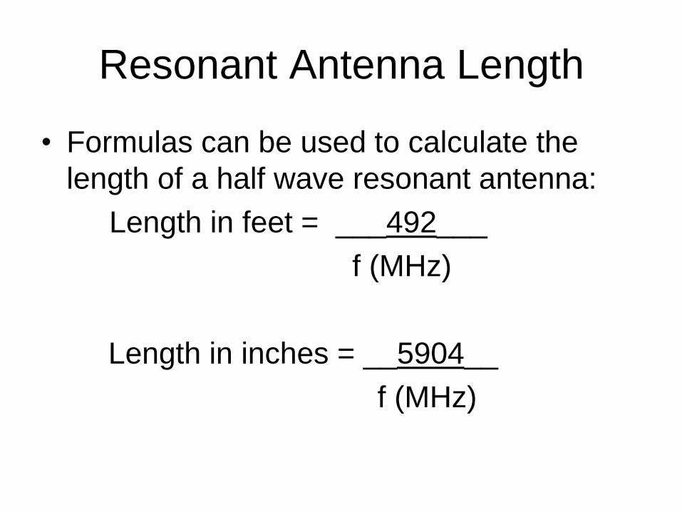
Resonant Antenna Length
• Formulas can be used to calculate the
length of a half wave resonant antenna:
Length in feet = ___492___
f (MHz)
Length in inches = __5904__
f (MHz)
Antenna “Modeling”
• XL, XC, Length, and 1/f are all directly
proportional so they scale
• For example, take the dimensions of a 3
element 6m beam and multiply them by 5.
– The new antenna will resonate at
50 MHz/5 = 10 MHz
– XL will be 5 times higher
– XC will be 5 times higher
– R will be about 50 ohms
Dipole Demonstration
• Experiments will be done at 146 MHz
– l/4 = 19 inches
– Feed line is electrically l/2 long = 31.9 inches
(length = l/2 * Velocity Factor (0.84))
– Chosen so measured impedance equals
antenna impedance
– Using MFJ-269 Pro Antenna Analyzer
• Giving SWR, Resonant Frequency, Reactance,
and Resistance of the Antenna
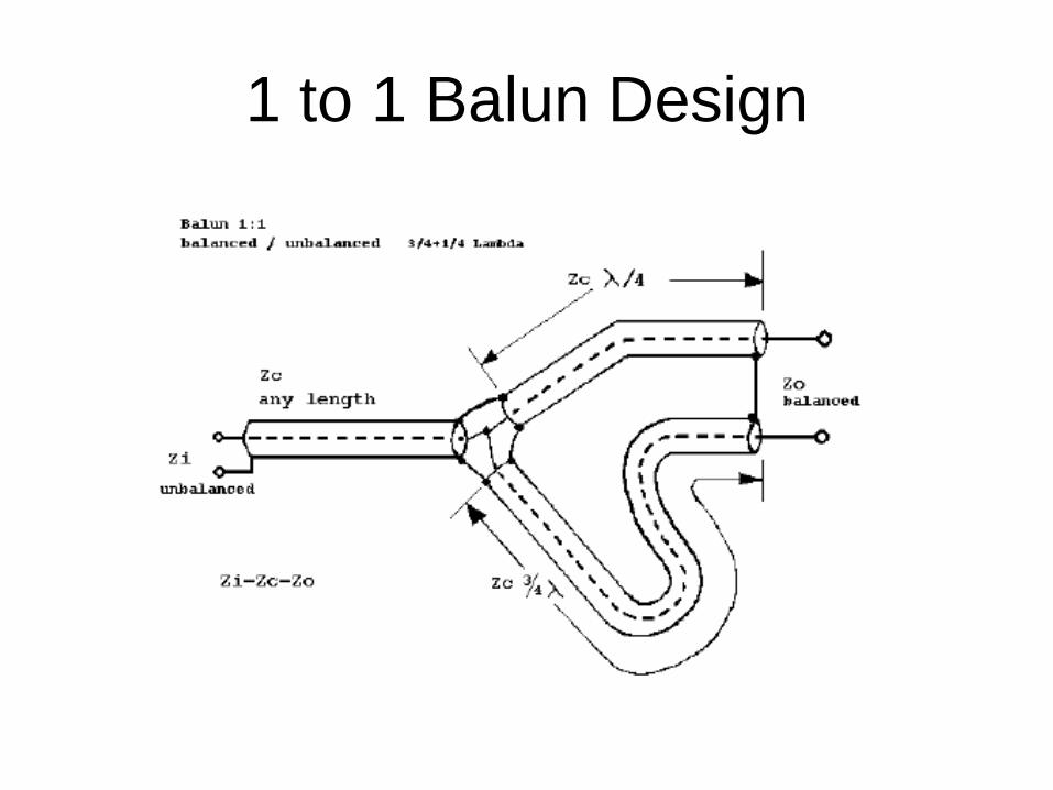
1 to 1 Balun Design

1. Demonstrate resistors (@ 14 MHz and 146 MHz)
- 51 Ohms
- 100 Ohms
- 27 Ohms
2. Demonstrate R/L/C circuit
3. Demonstrate ¼ l Vertical
- Without balun
- With balun
- With Inductors on feed line
Antenna Demonstrations
Antenna Demonstrations
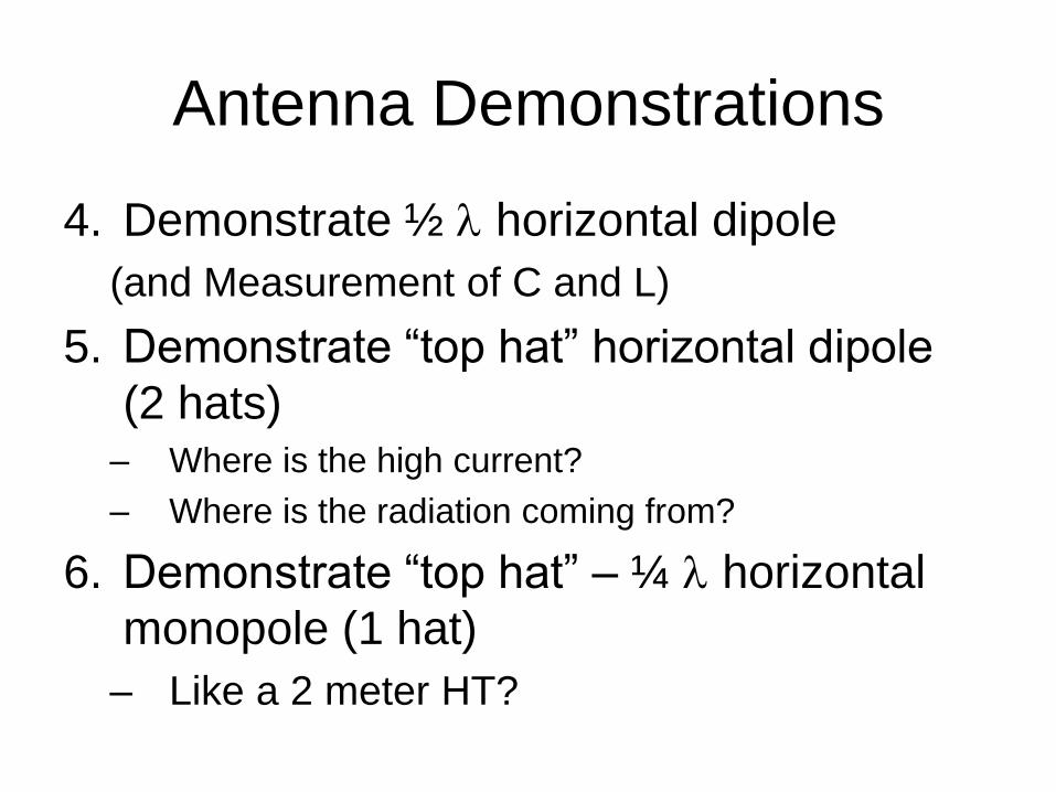
4. Demonstrate ½ l horizontal dipole
(and Measurement of C and L)
5. Demonstrate “top hat” horizontal dipole
(2 hats) – Where is the high current?
– Where is the radiation coming from?
6. Demonstrate “top hat” – ¼ l horizontal
monopole (1 hat)
– Like a 2 meter HT?
Antenna Demonstrations
7. Demonstrate short ¼ l vertical with “top
hat”
8. Demonstrate ¾ l – ¼ l Dipole
9. Demonstrate ¾ l – “top hat”
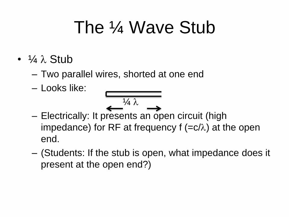
The ¼ Wave Stub
• ¼ l Stub
– Two parallel wires, shorted at one end
– Looks like:
¼ l
– Electrically: It presents an open circuit (high
impedance) for RF at frequency f (=c/l) at the open
end.
– (Students: If the stub is open, what impedance does it
present at the open end?)
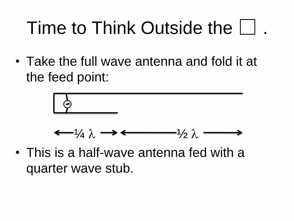
Time to Think Outside the .
• Take the full wave antenna and fold it at
the feed point:
¼ l ½ l
• This is a half-wave antenna fed with a
quarter wave stub.
Vertical Demonstration
10.Demonstrate ½ l vertical (“J” pole)
11.Demonstrate non-resonant vertical
12.Demonstrate non-resonant vertical with a
stub.
13.Demonstrate resonant 1 l J-pole
antenna with both ends grounded!
14.Demonstrate resonant ¾ l J-pole
antenna with both ends grounded!
Common Antennas
• One ¼ l monopole fed against ground
• Two ¼ l monopoles connected together ( a ½ l
dipole, center fed)
Less Common Antennas
• Two ¼ l monopoles connected together where
one or both are shortened with (a) capacitive
hat(s)
• One ¼ l monopole with a capacitive hat fed
against ground
• ¾ l conductor with one end at ground potential
(End fed ½ l “J”-pole)
• A full wave conductor with both ends at ground
potential!
Where’s Waldo?
• Find the antennas in the following pictures
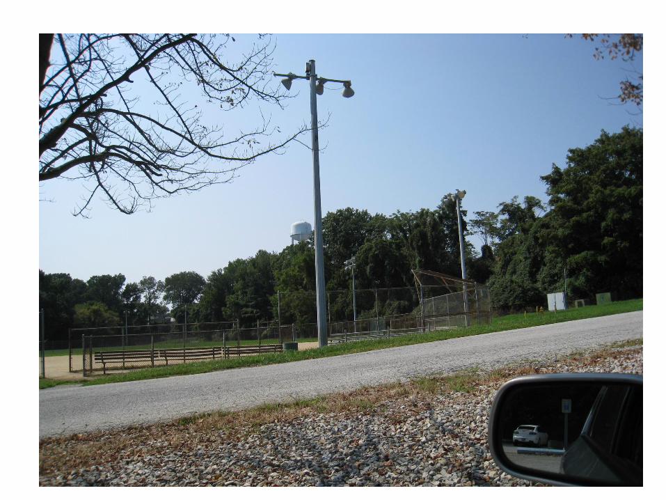
Light Pole
• 40 ft high
• Small capacitive hat
• Approximately ¾ l on 20m
• Would probably also work on 17m, 15m,
12m and 10m
• Feed two poles for a phased array?

Light Pole on 202
• Maybe 25 ft including horizontal section
• Approximately ¾ l on 12m
• Would probably also work on 10m
Traffic Sign + Supports
• Total length base to base: 300 ft
• Full wavelength on 80 m
• Would probably also work on 40m and
20m
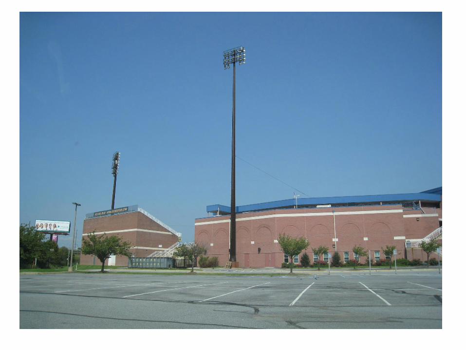
Light Standard at Frawley
Stadium
• Total height 130 ft
• Approximately ¾ l on 40m (longish)
• Would probably also work on 30m and
20m

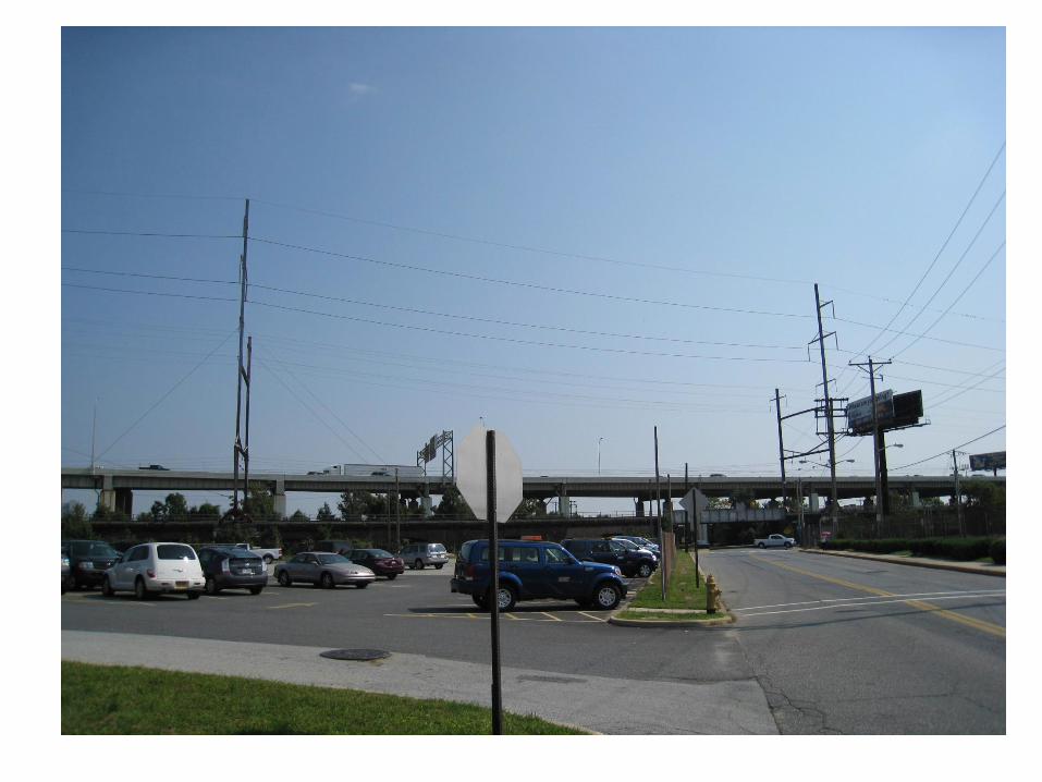
Billboard at Frawley Stadium
• Total height 60 ft, Great “top hat”
• Approximately ¾ l on 40m (top hat would
compensate for short length)
• Would probably also work on 30m and
20m
Power Poles Along Tracks
• Total length base to base: 300 ft
• Full wavelength on 80 m
• Would probably also work on 40m and
20m
So, What’s an Antenna?
Many things
you never
considered!!!