Embed Size (px)
Citation preview

Chapter 1: Introduction
Antennas and Propagation

Chapter 1Antennas and Propagation Slide 2
History of Antennas and Propagation
Timeline
1870 Maxwell’s Equations
80 Heinrich Hertz’s Loop Experiment (1886)
90
1900 Guglielmo Marconi (1901) Transatlantic Transmission
10 Spark gap telegraphy
20 Audio broadcasting
30
40 WWII: Microwave sources Radar
1950 MTS system in USA
60 Computers, Numerical CEM
70 Analog Cellular
80 GPS satellites launched
90 Digital cellular, wireless LAN
2000 Advanced integrated devices/MIMO
10 ???

Chapter 1Antennas and Propagation Slide 3
History of Antennas and Propagation
Timeline
1870 Maxwell’s Equations
80 Heinrich Hertz’s Loop Experiment (1886)
90
1900 Guglielmo Marconi (1901) Transatlantic Transmission
10 Spark gap telegraphy
20 Audio broadcasting
30
40 WWII: Microwave sources Radar
1950 MTS system in USA
60 Computers, Numerical CEM
70 Analog Cellular
80 GPS satellites launched
90 Digital cellular, wireless LAN
2000 Advanced integrated devices, MIMO
10 ???

Chapter 1Antennas and Propagation Slide 4
History of Antennas and Propagation
Timeline
1870 Maxwell’s Equations
80 Heinrich Hertz’s Loop Experiment (1886)
90
1900 Guglielmo Marconi (1901) Transatlantic Transmission
10 Spark gap telegraphy
20 Audio broadcasting
30
40 WWII: Microwave sources Radar
1950 MTS system in USA
60 Computers, Numerical CEM
70 Analog Cellular
80 GPS satellites launched
90 Digital cellular, wireless LAN
2000 Advanced integrated devices, MIMO
10 ???
Chapter 1Antennas and Propagation Slide 5
History of Antennas and Propagation
Timeline
1870 Maxwell’s Equations
80 Heinrich Hertz’s Loop Experiment (1886)
90
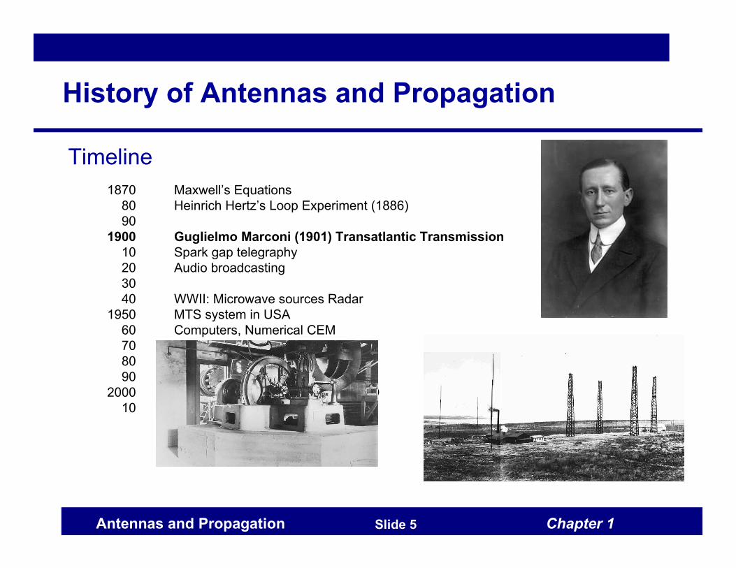
1900 Guglielmo Marconi (1901) Transatlantic Transmission
10 Spark gap telegraphy
20 Audio broadcasting
30
40 WWII: Microwave sources Radar
1950 MTS system in USA
60 Computers, Numerical CEM
70 Analog Cellular
80 GPS satellites launched
90 Digital cellular, wireless LAN
2000 Advanced integrated devices/MIMO
10 ???
Chapter 1Antennas and Propagation Slide 6
History of Antennas and Propagation
Timeline
1870 Maxwell’s Equations
80 Heinrich Hertz’s Loop Experiment (1886)
90
1900 Guglielmo Marconi (1901) Transatlantic Transmission
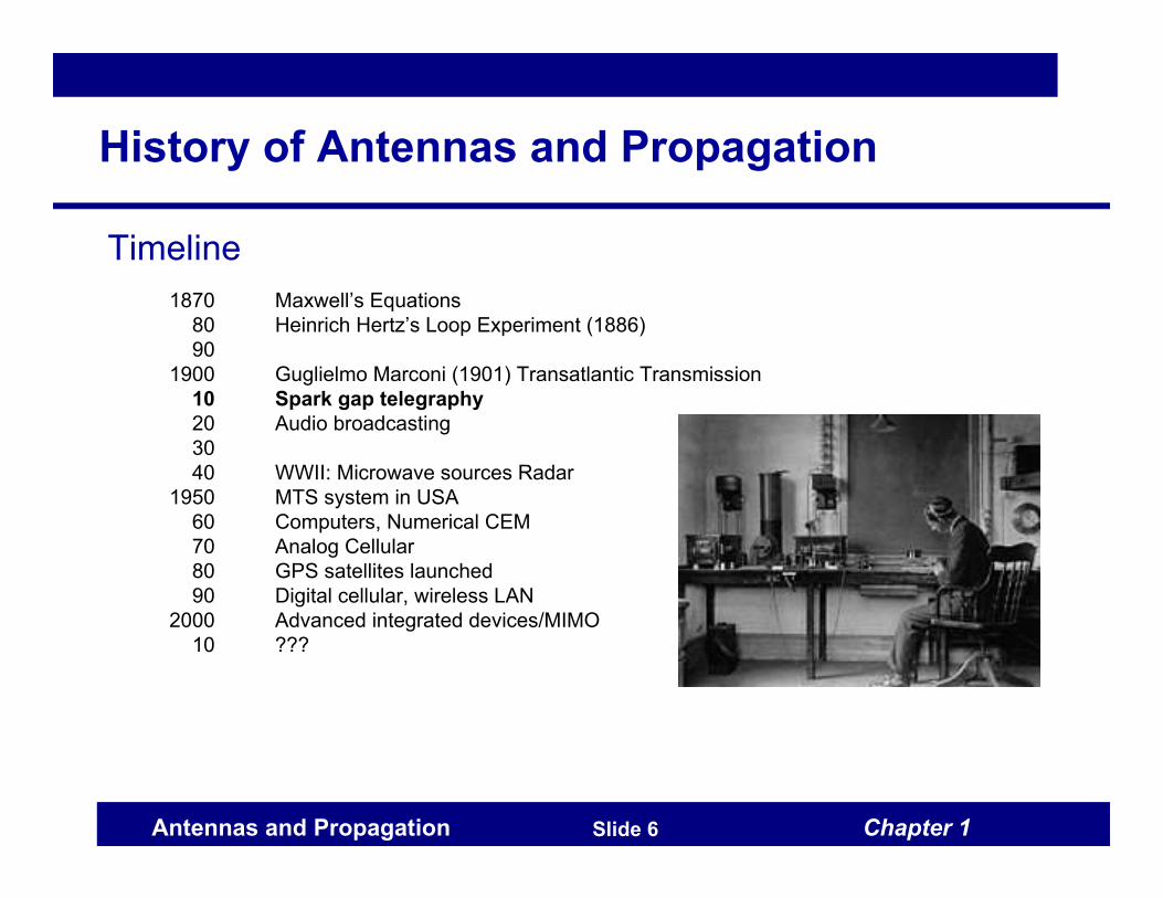
10 Spark gap telegraphy
20 Audio broadcasting
30
40 WWII: Microwave sources Radar
1950 MTS system in USA
60 Computers, Numerical CEM
70 Analog Cellular
80 GPS satellites launched
90 Digital cellular, wireless LAN
2000 Advanced integrated devices/MIMO
10 ???

Chapter 1Antennas and Propagation Slide 7
History of Antennas and Propagation
Timeline
1870 Maxwell’s Equations
80 Heinrich Hertz’s Loop Experiment (1886)
90
1900 Guglielmo Marconi (1901) Transatlantic Transmission
10 Spark gap telegraphy
20 Audio broadcasting
30
40 WWII: Microwave sources Radar
1950 MTS system in USA
60 Computers, Numerical CEM
70 Analog Cellular
80 GPS satellites launched
90 Digital cellular, wireless LAN
2000 Advanced integrated devices/MIMO
10 ???

Chapter 1Antennas and Propagation Slide 8
History of Antennas and Propagation
Timeline
1870 Maxwell’s Equations
80 Heinrich Hertz’s Loop Experiment (1886)
90
1900 Guglielmo Marconi (1901) Transatlantic Transmission
10 Spark gap telegraphy
20 Audio broadcasting
30
40 WWII: Microwave sources Radar
1950 MTS system in USA
60 Computers, Numerical CEM
70 Analog Cellular
80 GPS satellites launched
90 Digital cellular, wireless LAN
2000 Advanced integrated devices/MIMO
10 ???
Chapter 1Antennas and Propagation Slide 9
History of Antennas and Propagation
Timeline
1870 Maxwell’s Equations
80 Heinrich Hertz’s Loop Experiment (1886)
90
1900 Guglielmo Marconi (1901) Transatlantic Transmission
10 Spark gap telegraphy
20 Audio broadcasting
30
40 WWII: Microwave sources Radar
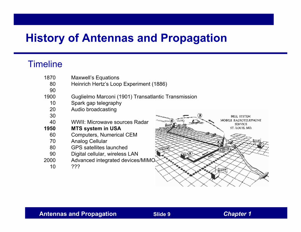
1950 MTS system in USA
60 Computers, Numerical CEM
70 Analog Cellular
80 GPS satellites launched
90 Digital cellular, wireless LAN
2000 Advanced integrated devices/MIMO
10 ???

Chapter 1Antennas and Propagation Slide 10
History of Antennas and Propagation
Timeline
1870 Maxwell’s Equations
80 Heinrich Hertz’s Loop Experiment (1886)
90
1900 Guglielmo Marconi (1901) Transatlantic Transmission
10 Spark gap telegraphy
20 Audio broadcasting
30
40 WWII: Microwave sources Radar
1950 MTS system in USA
60 Computers, Numerical CEM
70 Analog Cellular
80 GPS satellites launched
90 Digital cellular, wireless LAN
2000 Advanced integrated devices/MIMO
10 ???

Chapter 1Antennas and Propagation Slide 11
History of Antennas and Propagation
Timeline
1870 Maxwell’s Equations
80 Heinrich Hertz’s Loop Experiment (1886)
90
1900 Guglielmo Marconi (1901) Transatlantic Transmission
10 Spark gap telegraphy
20 Audio broadcasting
30
40 WWII: Microwave sources Radar
1950 MTS system in USA
60 Computers, Numerical CEM
70 Analog Cellular
80 GPS satellites launched
90 Digital cellular, wireless LAN
2000 Advanced integrated devices/MIMO
10 ???

Chapter 1Antennas and Propagation Slide 12
History of Antennas and Propagation
Timeline
1870 Maxwell’s Equations
80 Heinrich Hertz’s Loop Experiment (1886)
90
1900 Guglielmo Marconi (1901) Transatlantic Transmission
10 Spark gap telegraphy
20 Audio broadcasting
30
40 WWII: Microwave sources Radar
1950 MTS system in USA
60 Computers, Numerical CEM
70 Analog Cellular
80 GPS satellites launched
90 Digital cellular, wireless LAN
2000 Advanced integrated devices/MIMO
10 ???

Chapter 1Antennas and Propagation Slide 13
History of Antennas and Propagation
Timeline
1870 Maxwell’s Equations
80 Heinrich Hertz’s Loop Experiment (1886)
90
1900 Guglielmo Marconi (1901) Transatlantic Transmission
10 Spark gap telegraphy
20 Audio broadcasting
30
40 WWII: Microwave sources Radar
1950 MTS system in USA
60 Computers, Numerical CEM
70 Analog Cellular
80 GPS satellites launched
90 Digital cellular, wireless LAN
2000 Advanced integrated devices/MIMO
10 ???
Chapter 1Antennas and Propagation Slide 14
History of Antennas and Propagation
Timeline
1870 Maxwell’s Equations
80 Heinrich Hertz’s Loop Experiment (1886)
90
1900 Guglielmo Marconi (1901) Transatlantic Transmission
10 Spark gap telegraphy
20 Audio broadcasting
30
40 WWII: Microwave sources Radar
1950 MTS system in USA
60 Computers, Numerical CEM
70 Analog Cellular
80 GPS satellites launched
90 Digital cellular, wireless LAN
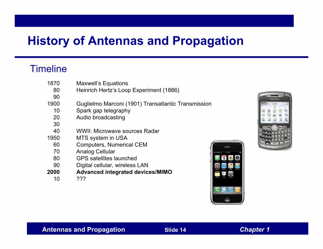
2000 Advanced integrated devices/MIMO
10 ???

Chapter 1Antennas and Propagation Slide 15
History of Antennas and Propagation
Timeline
1870 Maxwell’s Equations
80 Heinrich Hertz’s Loop Experiment (1886)
90
1900 Guglielmo Marconi (1901) Transatlantic Transmission
10 Spark gap telegraphy
20 Audio broadcasting
30
40 WWII: Microwave sources Radar
1950 MTS system in USA
60 Computers, Numerical CEM
70 Analog Cellular
80 GPS satellites launched
90 Digital cellular, wireless LAN
2000 Advanced integrated devices/MIMO
10 ???

Chapter 1Antennas and Propagation Slide 16
Antennas
Definition
Antennas are transducers that convert electrical signals into
propagating electromagnetic waves and vice versa.
Analogy
Sound: Speakers, Microphones

Chapter 1Antennas and Propagation Slide 17
Basic Antenna System (1)
Source
Equivalent circuit that generates signals
E.g. DSP, D/A converter, microwave oscillator, mixer
VgGenerator voltage
ZgGenerator input impedance
Chapter 1Antennas and Propagation Slide 18
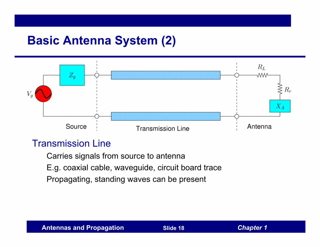
Basic Antenna System (2)
Transmission Line
Carries signals from source to antenna
E.g. coaxial cable, waveguide, circuit board trace
Propagating, standing waves can be present
Chapter 1Antennas and Propagation Slide 19
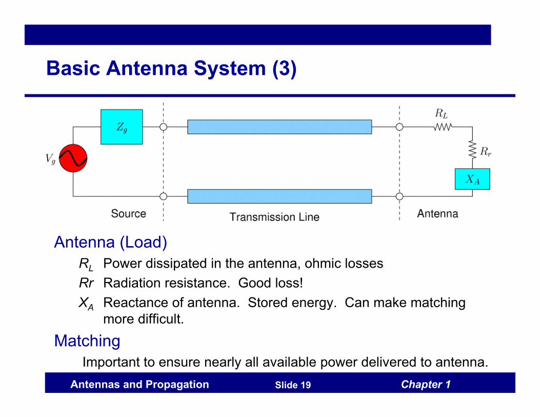
Basic Antenna System (3)
Antenna (Load)
RL Power dissipated in the antenna, ohmic losses
Rr Radiation resistance. Good loss!
XA Reactance of antenna. Stored energy. Can make matching
more difficult.
Matching
Important to ensure nearly all available power delivered to antenna.
Chapter 1Antennas and Propagation Slide 20
Antenna Design
Goals
Should be low-loss = high efficiency
Matched to a convenient impedance
Radiate (or receive) power in right “directions” and
polarizations
Be as compact as possible
Operate over required bandwidth
Propagation aspects
Right “directions” depends on environment
User/nearby objects affect antenna operation
Chapter 1Antennas and Propagation Slide 21
Importance of Good Antenna Design
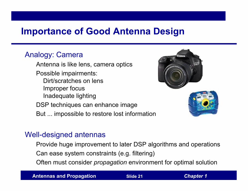
Analogy: Camera
Antenna is like lens, camera optics
Possible impairments:
Dirt/scratches on lens
Improper focus
Inadequate lighting
DSP techniques can enhance image
But ... impossible to restore lost information
Well-designed antennas
Provide huge improvement to later DSP algorithms and operations
Can ease system constraints (e.g. filtering)
Often must consider propagation environment for optimal solution

Chapter 1Antennas and Propagation Slide 22
Antenna Types: Wire Antennas
Wire Antennas
Dipole Monopole Loop
Properties
Simple
Low cost (a bent wire!)
Efficient
Single frequency
Chapter 1Antennas and Propagation Slide 23
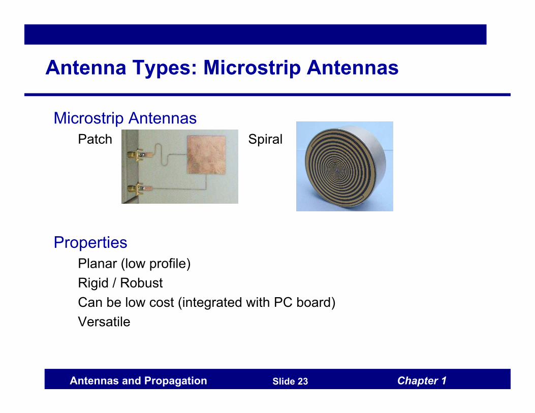
Antenna Types: Microstrip Antennas
Microstrip Antennas
Patch Spiral
Properties
Planar (low profile)
Rigid / Robust
Can be low cost (integrated with PC board)
Versatile

Chapter 1Antennas and Propagation Slide 24
Antenna Types: Aperture Antennas
Aperture Antennas
Horn Vivaldi Waveguide
Properties
Rigid (especially horn)
Wideband operation
Useful for
aerospace applications
antenna measurements
But, can be bulky / heavy

Chapter 1Antennas and Propagation Slide 25
Antenna Types: Conformal
Conformal Antennas
Cone
Properties
Surface is a degree of freedom to
optimize pattern
Or, given an existing surface, can use for antenna
Example: airplane wing, window, etc.
Design / fabrication more involved

Chapter 1Antennas and Propagation Slide 26
Antenna Types: Reflector Antennas
Reflector Antennas
Parabolic Dish Corner Reflector
Properties
Very narrow beam (high gain) possible
Bandwidth only limited by feed and size of reflector
But, can be bulky, expensive

Chapter 1Antennas and Propagation Slide 27
Antenna Types: Antenna Arrays
Antenna Arrays
Patch Array (WLAN) NRAO VLA
Properties
Gain enhancement over a single element
Dynamic/electronic steering of beam
Spatial diversity / multiplexing

Chapter 1Antennas and Propagation Slide 28
Antenna Operational Principles
1. Resonant Antennas
Designed to operate at one frequency. Analogy: guitar string.
Dipoles, loops, patches
2. Waveguide type antennas
Smooth transition from waveguide to free-space. Analogy: speaker
Very wide operational bandwidth
Horn antennas
Reflectors / Arrays
Can be considered method of modifying/focusing pattern of other
basic antenna types
Chapter 1Antennas and Propagation Slide 29
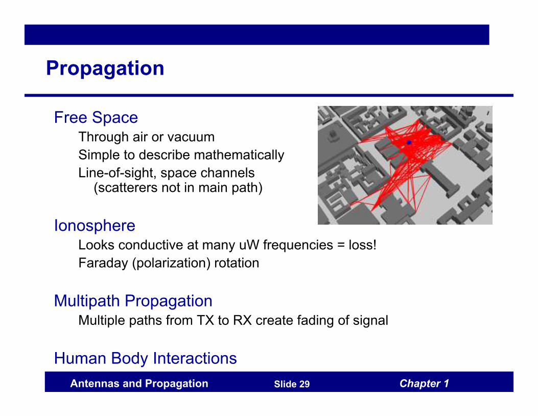
Propagation
Free SpaceThrough air or vacuum
Simple to describe mathematically
Line-of-sight, space channels (scatterers not in main path)
IonosphereLooks conductive at many uW frequencies = loss!
Faraday (polarization) rotation
Multipath PropagationMultiple paths from TX to RX create fading of signal
Human Body Interactions

Chapter 1Antennas and Propagation Slide 30
Course Organization
1. Electromagnetic (EM) Analysis (2 weeks)
Transmission Lines (review)
Vector Potentials / Wave Equation
Derive waves generated by source currents
in an arbitrary antenna
Far-field Radiation
Exact computation of fields can be costly
Often we are interested in fields far from antenna (radar, comm)
Far-field expressions usually much simpler
Duality/Reciprocity
Extremely useful properties of EM fields
Motivation
Funamental mathematical tools to predict antenna behavior

Chapter 1Antennas and Propagation Slide 31
Course Organization
2. Antenna Parameters (1 week)
Standard Antenna Terms and Parameters
Patterns
Gain
Bandwidth
Polarization
Input Impedance
Coupling
Motivation
Language to describe / compare antenna operation
Chapter 1Antennas and Propagation Slide 32
Course Organization
3. Antenna Types (2 weeks)
Basic Antenna Types
Show at least one example of each antenna type
Wire Antennas: Dipoles and loops
Planar Antennas: Patches
Aperture Antennas, Reflectors
Broadband, frequency-independent antennas
Motivation
See techniques (tricks) to analyze most antennas
Gain intuition: “see” how antennas work

Chapter 1Antennas and Propagation Slide 33
Course Organization
4. Antenna Arrays (2 weeks)
Element/Array Factor
Separate effect of individual elements, array
Mutual coupling
For closely-spaced antennas, fields interact
Beamforming, Nulling
Most basic and useful applications of arrays
Enhance signals of interest, suppress interference
Motivation
Array processing used in most advanced modern systems
Overcomes deficiencies of single elements

Chapter 1Antennas and Propagation Slide 34
Course Organization
5. Propagation (3 weeks)
Channel Modeling
Power laws (radar range equation)
Multipath: rays and clusters
Fading: Rayleigh, Rician, Shadowing
MIMO Modeling/Analysis
Random matrix models
Channel covariance
Diversity techniques
Channel capacity
Motivation
Understand how channel influences communications
Learn most important terms for research in this area

Chapter 1Antennas and Propagation Slide 35
Course Organization
6. Applications / Research (2 weeks)
MIMO
Space-Time Coding
Alamouti Scheme, VBLAST
Reconfigurable Antennas
Antennas whose properties can be dynamically changed / tuned
Radio Frequency Identification (RFID)
Ultra-Wideband Systems (UWB)
Motivation
See recent advances / uses of antennas
Get better picture of complete system

Chapter 1Antennas and Propagation Slide 36
Conclusion
Antennas and Propagation
Still an important area of research / development
Course gives basic tools to be proficient in this area