Embed Size (px)
Citation preview
DISSERTATION
Anthropomorphic Hand Optimizationbased on a Latent Space Analysis.
ausgeführt zum Zwecke der Erlangung des akademischen Grades eines Doktors dertechnischen Wissenschaften unter der Leitung von
Ao.Univ.Prof. Dipl.-Ing. Dr.techn. Heinz-Bodo SchmiedmayerInstitut für Mechanik und Mechatronik
Technische Universität Wien
und
Prof. Danica KragicCentre for Autonomous Systems, CSC
Königlich Technische Hochschule (KTH), Stockholm, Schweden
eingereicht an der Technischen Universität Wienbei der Fakultät für Maschinenwesen und Betriebswissenschaften
von
Dipl.-Ing.(FH) Thomas FeixMatrikelnummer: 0227312
Stadtplatz 93400 Klosterneuburg
Wien, im Oktober 2011
Erklärung zur Verfassung der Arbeit
Thomas FeixStadtplatz 93400 Klosterneuburg
Hiermit erkläre ich, dass ich diese Arbeit selbständig verfasst habe, dass ich dieverwendeten Quellen und Hilfsmittel vollständig angegeben habe und dass ich die Stellender Arbeit - einschließlich Tabellen, Karten und Abbildungen -, die anderen Werken oderdem Internet im Wortlaut oder dem Sinn nach entnommen sind, auf jeden Fall unterAngabe der Quelle als Entlehnung kenntlich gemacht habe.
(Ort, Datum) (Unterschrift Verfasser)
i
Acknowledgements
I would like to express my sincere gratitude to all who contributed to making this the-sis possible. My supervisors Prof. Schmiedmayer and Prof. Kragic provided valuableguidance and continuous support. Their comments and assistance were of great help.
As the research work was done within the European EC-FP7 project GRASP, I wouldlike to thank the concerned team members, too. It was highly inspiring to be part of such aproject and get to know scientists from all over Europe. In particular, I would like to thankJavier Romero of KTH Stockholm for the continuous collaboration and discussions. Healso deserves credit for creating the grasp images and for implementing the GMM/GMRcode for grasp classification. Thanks are also due to Heiner Deubel and René Gilster ofLMU Munich, where the human grasp data was recorded. Furthermore, I would like tothank the prosthetics company Otto Bock for providing me with the opportunity to workon this highly interesting topic.
Last but not least, I would like to thank my family and friends for supporting methroughout the past years.
ii
Abstract
Humans use the hand as their primary manipulator, performing a wide range of move-ments with it. An important sub-set of those movements are one handed grasps, on whichthe thesis focus on. To this day there is no consensus on the grasp types humans use andhow the hand kinematics influence the hand capabilities. As such knowledge is scarce,the design of artificial anthropomorphic hand is still depending to a large part on theintuition of its creators.
Within the thesis a comprehensive grasp taxonomy is developed, which incorporatesall major grasp types found in literature. This allows for a detailed description of onehanded static human grasping movements. Those movements are recorded, resulting ina dataset that consists of different grasp trajectories. That data is then projected onto alow dimensional space using a nonlinear dimensionality reduction algorithm. That allowsto represent the human grasping movements in a more compact fashion.
In order to provide a design tool which evaluates the level of anthropomorphism ofartificial hands, the data is processed further. The trajectories of artificial hands areprojected to the human spanned low dimensional space. That allows for a straightforwardand intuitive comparison between human and machine. An indication for a human-likehand is that its movements have a large overlap of the human space.
That method is applied to grade existing hands and to show how different designchoices influence the level of anthropomorphism of artificial hands. Finally, new handdesigns are developed. Starting from existing hands, the kinematic structure is alteredand new actuators are added in order to increase the overlap with the human. Thoseimproved hands need only a few control signals, but are able to mimic large proportionsof the human hand capabilities.
iii
Kurzfassung
Menschen verwenden ihre Hand als ihr primäres Werkzeug und setzen sie in einer Vielzahlvon Bewegungen ein. Eine wichtige Untergruppe aller Bewegungen sind einhändige Griffe,die im Fokus dieser Arbeit stehen. Bis heute gibt es keinen Konsens welche Grifftypenverwendet werden und wie die Handkinematik die Fähigkeiten der Hand beeinflusst. Auf-grund des Mangels dieses Wissens, ist ein künstliches Handdesign hauptsächlich von derIntuition seines Erbauers abhängig.
Die Arbeit entwickelt eine vollständige Griffklassifizierung, die alle vorhergegangenenArbeiten beinhaltet. Diese Taxonomie erlaubt es einhändige, statische Griffbewegun-gen genau zu beschreiben. Diese Bewegungen werden dann gemessen und erzeugen einenDatensatz der diese Greifbewegungen beherbergt. Diese Daten werden mit einem nichtlin-earen Algorithmus zur Dimensionalitätsreduktion weiterverarbeitet und dadurch könnensie in einem niederdimensionalen Raum dargestellt werden.
Um ein Werkzeug zur Bestimmung der Menschenähnlichkeit von künstlichen Händenzu kreieren, werden diese Daten herangezogen. Die Bewegungen einer künstlichen Handwerden in den Raum der menschlichen Bewegungen projiziert um einen direkten Vergleichzwischen Mensch und Maschine zu schaffen. Ein Indiz für ein anthropomorphes Designist, dass die Bewegungen einen großen Teil des menschlichen Raumes abdecken. DieMethode wird verwendet um bestehende Hände zu bewerten und um zu zeigen wie ver-schiedene Designelemente die Menschenähnlichkeit beeinflussen können. Schlussendlichwerden, ausgehend von existierenden Designs, neue, verbesserte Hände entwickelt. Diesebenötigen nur wenige Steuersignale, aber können große Teile der menschlichen Fähigkeitennachahmen.
iv
Contents
1 Introduction 11.1 Motivation . . . . . . . . . . . . . . . . . . . . . . . . . . . . . . . . . . . . 11.2 Contributions . . . . . . . . . . . . . . . . . . . . . . . . . . . . . . . . . . 21.3 Thesis Outline . . . . . . . . . . . . . . . . . . . . . . . . . . . . . . . . . . 3
2 State of the Art 42.1 Anatomy of the Hand . . . . . . . . . . . . . . . . . . . . . . . . . . . . . . 4
2.1.1 Forearm . . . . . . . . . . . . . . . . . . . . . . . . . . . . . . . . . 42.1.2 Metacarpus . . . . . . . . . . . . . . . . . . . . . . . . . . . . . . . 52.1.3 Metacarpal Joints . . . . . . . . . . . . . . . . . . . . . . . . . . . . 62.1.4 Interphalangeal Joints . . . . . . . . . . . . . . . . . . . . . . . . . 72.1.5 Thumb . . . . . . . . . . . . . . . . . . . . . . . . . . . . . . . . . . 7
2.2 Theory of Grasping . . . . . . . . . . . . . . . . . . . . . . . . . . . . . . . 92.2.1 Opposition types . . . . . . . . . . . . . . . . . . . . . . . . . . . . 102.2.2 Power, Precision, Intermediate Grasp . . . . . . . . . . . . . . . . . 102.2.3 Virtual Fingers . . . . . . . . . . . . . . . . . . . . . . . . . . . . . 112.2.4 Grasp Taxonomies . . . . . . . . . . . . . . . . . . . . . . . . . . . 12
2.3 Artificial Hands . . . . . . . . . . . . . . . . . . . . . . . . . . . . . . . . . 122.3.1 Prosthetic Hands . . . . . . . . . . . . . . . . . . . . . . . . . . . . 122.3.2 Anthropomorphic Robotic Hands . . . . . . . . . . . . . . . . . . . 132.3.3 Hand Control . . . . . . . . . . . . . . . . . . . . . . . . . . . . . . 152.3.4 Optimal Hand Designs . . . . . . . . . . . . . . . . . . . . . . . . . 16
2.4 Kinematic Chains . . . . . . . . . . . . . . . . . . . . . . . . . . . . . . . . 172.4.1 Degrees of Freedom . . . . . . . . . . . . . . . . . . . . . . . . . . . 172.4.2 Denavit - Hartenberg Formalism . . . . . . . . . . . . . . . . . . . . 192.4.3 Human Hand Models . . . . . . . . . . . . . . . . . . . . . . . . . . 20
2.5 Unsupervised Machine Learning . . . . . . . . . . . . . . . . . . . . . . . . 23
v
Contents
2.5.1 Principal Components Analysis . . . . . . . . . . . . . . . . . . . . 232.5.2 Isomap . . . . . . . . . . . . . . . . . . . . . . . . . . . . . . . . . . 272.5.3 Locally Linear Embedding . . . . . . . . . . . . . . . . . . . . . . . 272.5.4 Gaussian Process Latent Variable Models . . . . . . . . . . . . . . . 28
3 Comprehensive Grasp Taxonomy 313.1 Grasp Definition . . . . . . . . . . . . . . . . . . . . . . . . . . . . . . . . 313.2 Compared Taxonomies . . . . . . . . . . . . . . . . . . . . . . . . . . . . . 32
3.2.1 Schlesinger . . . . . . . . . . . . . . . . . . . . . . . . . . . . . . . . 323.2.2 Slocum and Pratt . . . . . . . . . . . . . . . . . . . . . . . . . . . . 323.2.3 Cooney and Chao . . . . . . . . . . . . . . . . . . . . . . . . . . . . 333.2.4 Kamakura et. al . . . . . . . . . . . . . . . . . . . . . . . . . . . . 343.2.5 Lister . . . . . . . . . . . . . . . . . . . . . . . . . . . . . . . . . . 343.2.6 Elliott and Connolly . . . . . . . . . . . . . . . . . . . . . . . . . . 343.2.7 Lyons . . . . . . . . . . . . . . . . . . . . . . . . . . . . . . . . . . 403.2.8 Kroemer . . . . . . . . . . . . . . . . . . . . . . . . . . . . . . . . . 403.2.9 Cutkosky . . . . . . . . . . . . . . . . . . . . . . . . . . . . . . . . 403.2.10 Kang and Ikeuchi . . . . . . . . . . . . . . . . . . . . . . . . . . . . 413.2.11 Light et al. . . . . . . . . . . . . . . . . . . . . . . . . . . . . . . . 443.2.12 Exner . . . . . . . . . . . . . . . . . . . . . . . . . . . . . . . . . . 443.2.13 Edwards et al. . . . . . . . . . . . . . . . . . . . . . . . . . . . . . . 463.2.14 Kapandji . . . . . . . . . . . . . . . . . . . . . . . . . . . . . . . . . 49
3.3 Comparison Sheet . . . . . . . . . . . . . . . . . . . . . . . . . . . . . . . . 513.4 Grasp List . . . . . . . . . . . . . . . . . . . . . . . . . . . . . . . . . . . . 513.5 Comprehensive Taxonomy . . . . . . . . . . . . . . . . . . . . . . . . . . . 533.6 Discussion . . . . . . . . . . . . . . . . . . . . . . . . . . . . . . . . . . . . 57
4 Quantification of Anthropomorphic Hand Performance 584.1 System Description . . . . . . . . . . . . . . . . . . . . . . . . . . . . . . . 584.2 Overlap Measure . . . . . . . . . . . . . . . . . . . . . . . . . . . . . . . . 614.3 The Latent Space . . . . . . . . . . . . . . . . . . . . . . . . . . . . . . . . 63
4.3.1 Data Acquisition . . . . . . . . . . . . . . . . . . . . . . . . . . . . 634.3.2 Data Set . . . . . . . . . . . . . . . . . . . . . . . . . . . . . . . . . 664.3.3 Rotation Representation . . . . . . . . . . . . . . . . . . . . . . . . 674.3.4 Influence of the Kernel Width . . . . . . . . . . . . . . . . . . . . . 684.3.5 Metrics on Latent Space Quality . . . . . . . . . . . . . . . . . . . 694.3.6 Model Comparison . . . . . . . . . . . . . . . . . . . . . . . . . . . 744.3.7 The Selected Model . . . . . . . . . . . . . . . . . . . . . . . . . . . 75
vi
Contents
4.4 Projection of Existing Hands . . . . . . . . . . . . . . . . . . . . . . . . . . 794.4.1 SensorHand . . . . . . . . . . . . . . . . . . . . . . . . . . . . . . . 794.4.2 Michelangelo Hand . . . . . . . . . . . . . . . . . . . . . . . . . . . 814.4.3 FRH-4 Hand . . . . . . . . . . . . . . . . . . . . . . . . . . . . . . 844.4.4 Human Hand Model . . . . . . . . . . . . . . . . . . . . . . . . . . 854.4.5 Principal Components of the Space . . . . . . . . . . . . . . . . . . 86
4.5 Discussion . . . . . . . . . . . . . . . . . . . . . . . . . . . . . . . . . . . . 90
5 Optimizing Kinematic Hand Setups 925.1 Sensitivity Study . . . . . . . . . . . . . . . . . . . . . . . . . . . . . . . . 92
5.1.1 SensorHand . . . . . . . . . . . . . . . . . . . . . . . . . . . . . . . 945.1.2 Michelangelo . . . . . . . . . . . . . . . . . . . . . . . . . . . . . . 945.1.3 FR-H 4 Hand . . . . . . . . . . . . . . . . . . . . . . . . . . . . . . 965.1.4 Discussion . . . . . . . . . . . . . . . . . . . . . . . . . . . . . . . . 97
5.2 Optimization of Kinematic Parameters . . . . . . . . . . . . . . . . . . . . 995.2.1 SensorHand Thumb . . . . . . . . . . . . . . . . . . . . . . . . . . . 1005.2.2 Linear Human Hand Model . . . . . . . . . . . . . . . . . . . . . . 1035.2.3 Michelangelo Couplings . . . . . . . . . . . . . . . . . . . . . . . . . 1075.2.4 Michelangelo with Human Thumb 3D . . . . . . . . . . . . . . . . . 108
5.3 Validation of Design Elements . . . . . . . . . . . . . . . . . . . . . . . . . 1105.3.1 Michelangelo Couplings with Human Thumb 3D . . . . . . . . . . . 1105.3.2 Michelangelo with Independent Index . . . . . . . . . . . . . . . . . 1125.3.3 Michelangelo Underactuated Finger Joints . . . . . . . . . . . . . . 1135.3.4 Michelangelo with Human Thumb and Underactuation . . . . . . . 115
5.4 Discussion . . . . . . . . . . . . . . . . . . . . . . . . . . . . . . . . . . . . 118
6 Conclusion 1206.1 Outlook . . . . . . . . . . . . . . . . . . . . . . . . . . . . . . . . . . . . . 121
Glossary 123
List of Figures 125
List of Tables 128
Bibliography 129
A Curriculum Vitae 140
vii

Chapter 1Introduction
1.1 Motivation
The world around us determines how the human hand is used and how we manipulateobjects. In human-built environments the relation is also reversed – we built objects insuch a way as that they suit our dexterity. Commonly, objects that are supposed to bemanipulated by humans have roughly the size of the human hand and have an intendedway to be used. How would those objects look like if the kinematic structure of the humanhand would be majorly different? Would we still use mugs, pens etc. the same way andcreate objects with the same shape? Those questions are not tackled in the thesis but aremotivating ones.
Even though we use the hand everyday, its function is not well understood. A lotof work has been dedicated to structuring the human hand movements. Various grasptaxonomies have been proposed, but there is no real consensus on the existing grasptypes. Additionally, it is not known which grasp types are frequently used in everydaytasks, and which are used only very seldom. Such knowledge could be of benefit for manyapplications like designing artificial hands, human-robot interaction and many more.
The human hand is still unmatched by any artificial design, therefore a lot of efforthas been taken to mimic the human hand functionality. That is the case in prosthetics aswell as robotics. In order to become more human-like, new motors and joints were addedresulting in hands with a very complex structure. In the case of robotics, the number ofmotors can even exceed the human. The potential of such a hand is very large, but due tocontrol problems the actual hand capabilities are much lower [1]. In the case of prostheticssuch a large degree of complexity has not been reached due to the mechanical challengessuch a hand design poses. The system has to be human-sized and self-contained, thereforeonly a few actuators can be placed within the hand. Still, only a few independent controlsignals pose a serious challenge to the user. Contemporary methods only allow the human
1
Chapter 1. Introduction
to control one Degree of Freedom (DoF) at a time, thus multiple movements have to beperformed sequentially [2]. In that case a proper interface between the human and theprosthetic hand is the bottleneck [3].
The lessons learnt from this limitations are the same for robotic and prosthetic hands.The guideline on how such a hand should be built is that the control space of the handshould be low dimensional, thus diminishing the problems mentioned above. One shouldtry to incorporate as much functionality as possible directly into the kinematic setup,without adding more control signals. Additionally, such a hand will be simpler to manu-facture, as additional actuators and joints pose challenges in terms of the design. In thecase of prosthetics that would have other benefits as well – hand weight, speed, strengthand reliability are key factors for user acceptance [4,5]. A simple design will leave enoughmargin, so those goals can be achieved as well.
For a few special cases it is possible to determine the quality of a hand model insimulation. Yet, at the moment there are no principled methods that allow to determinethe functionality of an artificial hand prior to realization. The goal is to estimate the gapbetween the human and artificial hand prior to realization. Such a measure is importantas it allows to iterative over new hand designs in a much faster and more efficient waycompared to the classical approach of realizing hand prototypes.
1.2 Contributions
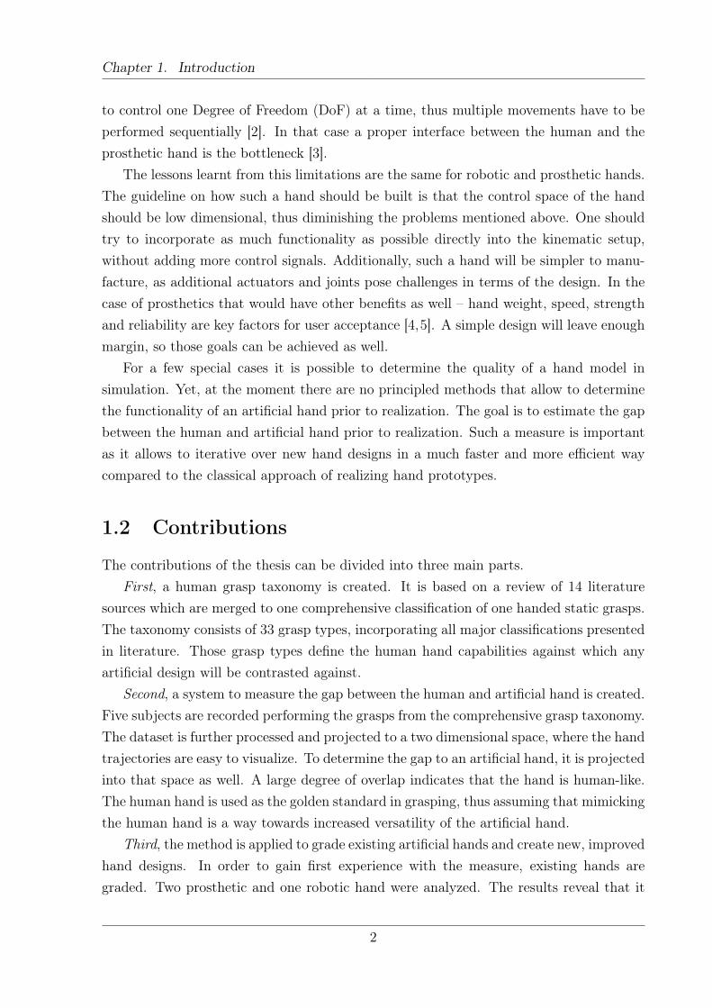
The contributions of the thesis can be divided into three main parts.First, a human grasp taxonomy is created. It is based on a review of 14 literature
sources which are merged to one comprehensive classification of one handed static grasps.The taxonomy consists of 33 grasp types, incorporating all major classifications presentedin literature. Those grasp types define the human hand capabilities against which anyartificial design will be contrasted against.
Second, a system to measure the gap between the human and artificial hand is created.Five subjects are recorded performing the grasps from the comprehensive grasp taxonomy.The dataset is further processed and projected to a two dimensional space, where the handtrajectories are easy to visualize. To determine the gap to an artificial hand, it is projectedinto that space as well. A large degree of overlap indicates that the hand is human-like.The human hand is used as the golden standard in grasping, thus assuming that mimickingthe human hand is a way towards increased versatility of the artificial hand.
Third, the method is applied to grade existing artificial hands and create new, improvedhand designs. In order to gain first experience with the measure, existing hands aregraded. Two prosthetic and one robotic hand were analyzed. The results reveal that it
2
Chapter 1. Introduction
is important that the general kinematic setup has to be human-like, it is not sufficient toadd many actuators in order to become anthropomorphic. To improve the hand designs,new actuators and joints are added, changing the kinematic structure. It is shown thatby small adaptations of existing hands major improvements can be achieved.
1.3 Thesis Outline
The thesis starts with Chapter 2 by giving background information the thesis is basedupon. That includes basic information on the human hand anatomy as well as meansto analyze human grasping in a structured way. Also, a method to describe kinematicchains as well as state of the art prosthetic and robotic hands are presented. Finally, themathematical basics of dimensionality reduction are given. That is needed as the measureto determine the level of anthropomorphism of artificial hands is heavily based on such amethod.
Chapter 3 develops a comprehensive grasp taxonomy which is based on all majorpublications. The classification defines the movements of the human hand against whichartificial hands are contrasted.
Chapter 4 presents a measure to determine the anthropomorphism of artificial hands.A large proportion of that Chapter is dedicated to finding an optimal low dimensionalembedding that is a crucial element of the measure. Finally, it grades existing handdesigns to gain first experience with the system.
Chapter 5 goes one step further, using the measure to create new, improved hands.That is achieved by two approaches. The first one optimizes kinematic parameters ofartificial hands and the second adds new components to existing hands and determinestheir influence on the capabilities of the hand.
Finally, in Chapter 6 a conclusion is given. It sums up the results achieved in thethesis and proposes how the research can be continued.
3
Chapter 2State of the Art
The approach presented in the thesis is multidisciplinary. It does not belong to one specificfield, therefore knowledge of many different areas is needed. This Chapter presents onlythe relevant background, without going too much into detail.
The first two Sections are of high relevance for Chapter 3. It is important to knowhow the human hand works and to understand the “language” describing the movements.Therefore Section 2.1 presents the human hand anatomy and which joints confer thehuman hand. Additionally, Section 2.2 presents how the human hand movements can beanalyzed in a structured way and describes concepts in grasping.
The next three Sections are important for Chapter 4. A human grasp dataset isprojected onto a low dimensional space using an unsupervised machine learning algorithmpresented in Section 2.5. Artificial hands are projected into that space as well, in orderto compare human and machine. Such a hand is defined via five kinematic chains, wherethe mathematical background is presented in Section 2.4. The tested hands reproducemovements of existing prosthetic and robotic hands as presented in Section 2.3.
2.1 Anatomy of the Hand
This section gives a short overview over the anatomy of the human hand. The focus ofthis thesis is on the human hand, therefore most details will be given on the hand joints.The arm itself is out of scope, as its main purpose is to position the hand.
2.1.1 Forearm
On the forearm many of the muscles which articulate the fingers are located. Due to thehigh dexterity of the human hand a lot of different muscles are needed to achieve this highdegree of independence between the joints of the hand. Figure 2.1(a) and Figure 2.1(b)
4
Chapter 2. State of the Art
(a) Extensor muscles on the forearm.
(b) Flexor muscles on the forearm.
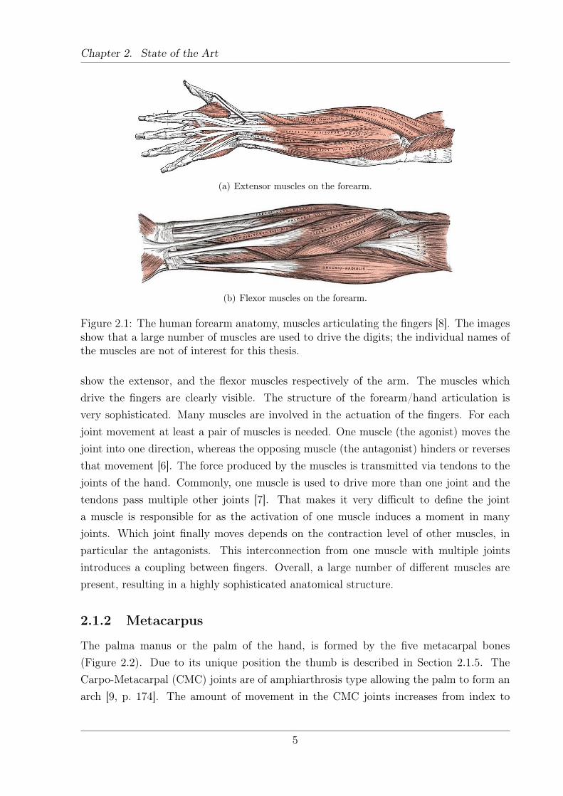
Figure 2.1: The human forearm anatomy, muscles articulating the fingers [8]. The imagesshow that a large number of muscles are used to drive the digits; the individual names ofthe muscles are not of interest for this thesis.
show the extensor, and the flexor muscles respectively of the arm. The muscles whichdrive the fingers are clearly visible. The structure of the forearm/hand articulation isvery sophisticated. Many muscles are involved in the actuation of the fingers. For eachjoint movement at least a pair of muscles is needed. One muscle (the agonist) moves thejoint into one direction, whereas the opposing muscle (the antagonist) hinders or reversesthat movement [6]. The force produced by the muscles is transmitted via tendons to thejoints of the hand. Commonly, one muscle is used to drive more than one joint and thetendons pass multiple other joints [7]. That makes it very difficult to define the jointa muscle is responsible for as the activation of one muscle induces a moment in manyjoints. Which joint finally moves depends on the contraction level of other muscles, inparticular the antagonists. This interconnection from one muscle with multiple jointsintroduces a coupling between fingers. Overall, a large number of different muscles arepresent, resulting in a highly sophisticated anatomical structure.
2.1.2 Metacarpus
The palma manus or the palm of the hand, is formed by the five metacarpal bones(Figure 2.2). Due to its unique position the thumb is described in Section 2.1.5. TheCarpo-Metacarpal (CMC) joints are of amphiarthrosis type allowing the palm to form anarch [9, p. 174]. The amount of movement in the CMC joints increases from index to
5
Chapter 2. State of the Art
Fingers
Digits
IP
MCP
CMC
PIP
DIP
Intermediate phalanges
Proximal phalanges
Distal phalanges
Metacarpals
Carpals
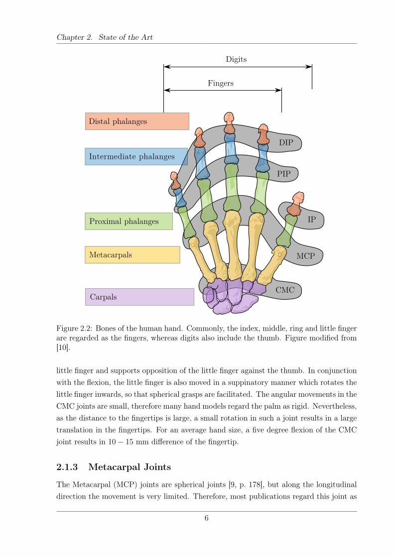
Figure 2.2: Bones of the human hand. Commonly, the index, middle, ring and little fingerare regarded as the fingers, whereas digits also include the thumb. Figure modified from[10].
little finger and supports opposition of the little finger against the thumb. In conjunctionwith the flexion, the little finger is also moved in a suppinatory manner which rotates thelittle finger inwards, so that spherical grasps are facilitated. The angular movements in theCMC joints are small, therefore many hand models regard the palm as rigid. Nevertheless,as the distance to the fingertips is large, a small rotation in such a joint results in a largetranslation in the fingertips. For an average hand size, a five degree flexion of the CMCjoint results in 10− 15 mm difference of the fingertip.
2.1.3 Metacarpal Joints
The Metacarpal (MCP) joints are spherical joints [9, p. 178], but along the longitudinaldirection the movement is very limited. Therefore, most publications regard this joint as
6
Chapter 2. State of the Art
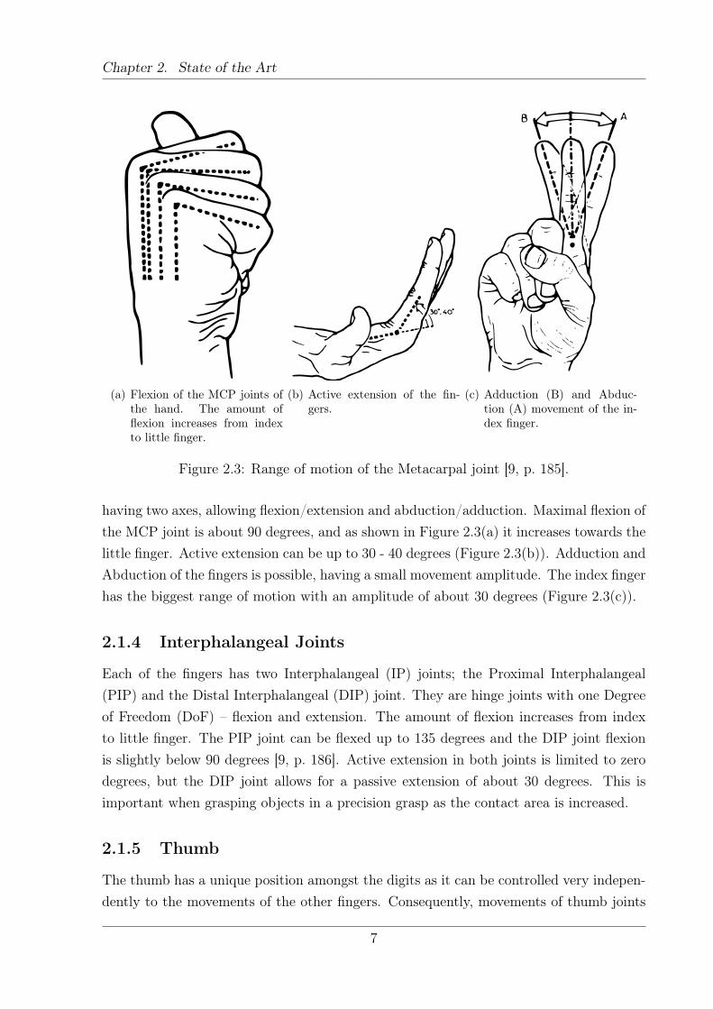
(a) Flexion of the MCP joints ofthe hand. The amount offlexion increases from indexto little finger.
(b) Active extension of the fin-gers.
(c) Adduction (B) and Abduc-tion (A) movement of the in-dex finger.
Figure 2.3: Range of motion of the Metacarpal joint [9, p. 185].
having two axes, allowing flexion/extension and abduction/adduction. Maximal flexion ofthe MCP joint is about 90 degrees, and as shown in Figure 2.3(a) it increases towards thelittle finger. Active extension can be up to 30 - 40 degrees (Figure 2.3(b)). Adduction andAbduction of the fingers is possible, having a small movement amplitude. The index fingerhas the biggest range of motion with an amplitude of about 30 degrees (Figure 2.3(c)).
2.1.4 Interphalangeal Joints
Each of the fingers has two Interphalangeal (IP) joints; the Proximal Interphalangeal(PIP) and the Distal Interphalangeal (DIP) joint. They are hinge joints with one Degreeof Freedom (DoF) – flexion and extension. The amount of flexion increases from indexto little finger. The PIP joint can be flexed up to 135 degrees and the DIP joint flexionis slightly below 90 degrees [9, p. 186]. Active extension in both joints is limited to zerodegrees, but the DIP joint allows for a passive extension of about 30 degrees. This isimportant when grasping objects in a precision grasp as the contact area is increased.
2.1.5 Thumb
The thumb has a unique position amongst the digits as it can be controlled very indepen-dently to the movements of the other fingers. Consequently, movements of thumb joints
7
Chapter 2. State of the Art
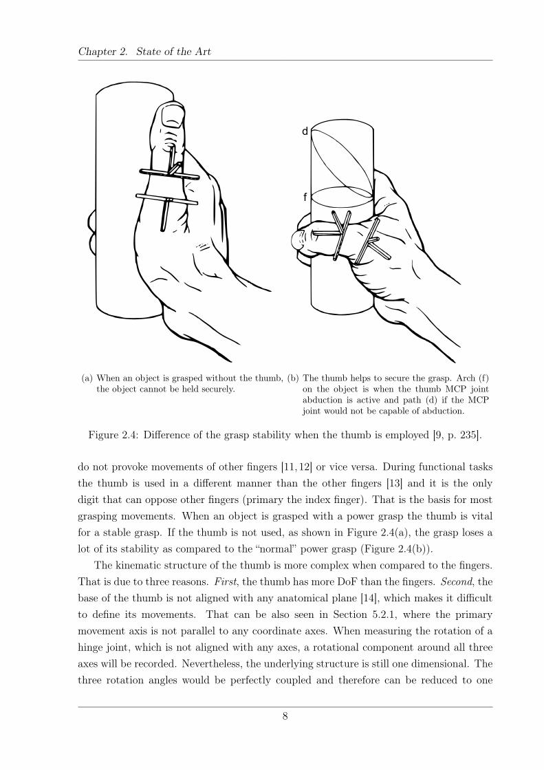
(a) When an object is grasped without the thumb,the object cannot be held securely.
d
f
(b) The thumb helps to secure the grasp. Arch (f)on the object is when the thumb MCP jointabduction is active and path (d) if the MCPjoint would not be capable of abduction.
Figure 2.4: Difference of the grasp stability when the thumb is employed [9, p. 235].
do not provoke movements of other fingers [11, 12] or vice versa. During functional tasksthe thumb is used in a different manner than the other fingers [13] and it is the onlydigit that can oppose other fingers (primary the index finger). That is the basis for mostgrasping movements. When an object is grasped with a power grasp the thumb is vitalfor a stable grasp. If the thumb is not used, as shown in Figure 2.4(a), the grasp loses alot of its stability as compared to the “normal” power grasp (Figure 2.4(b)).
The kinematic structure of the thumb is more complex when compared to the fingers.That is due to three reasons. First, the thumb has more DoF than the fingers. Second, thebase of the thumb is not aligned with any anatomical plane [14], which makes it difficultto define its movements. That can be also seen in Section 5.2.1, where the primarymovement axis is not parallel to any coordinate axes. When measuring the rotation of ahinge joint, which is not aligned with any axes, a rotational component around all threeaxes will be recorded. Nevertheless, the underlying structure is still one dimensional. Thethree rotation angles would be perfectly coupled and therefore can be reduced to one
8
Chapter 2. State of the Art
parameter. Third, the movement amplitudes of certain joint rotations are rather small,therefore not easily visible. The contribution of those small movements is still importantfor the thumb function. Those three facts combined make the thumb the most complexsystem of the five digits [9, p. 208].
The Carpo-Metacarpal joint (Figure 2.2) of the thumb is a saddle joint having 2 DoF.Kinematically this joint can be regarded as a universal joint allowing flexion/extensionand abduction/adduction, rotation about a longitudinal axis is prevented by the jointsurfaces. The Metacarpal (MCP) joint has 2 joint axes, allowing flexion/extension andabduction/adduction. Little rotation about the longitudinal axis is possible [9], but isnormally not regarded as a DoF. Figure 2.4(b) highlights the importance of the abduc-tion/adduction capability of this joint. The arch (f) on the object shows how the fingerwraps around the object with normal thumb function. If the MCP joint lacked thatab/adduction capability, the contact area would be more like the elliptic arch (d) whichdecreases the grasp stability [9, p. 234]. In contrast to the other fingers, the thumb hasonly two phalangeal bones, which are connected via the Interphalangeal (IP) joint, a hingejoint. In total, these movements sum up to five DoF for the thumb.
2.2 Theory of Grasping
The hand is a complex system and its usage is even more complex. It can be used in a vastvariety of tasks. Such as grasping, pushing, holding objects and expressing emotions. Asthis is an enormous range, the thesis focuses on human grasping with one hand. Still, thatis a large and diverse subset. Various authors have tried to structure those movements inorder to gain insights on the human hand deployment. This is done by applying differentclassification principles.
First, there is a rough discrimination for human hand motions into two main groups[15, p. 902]:
Prehensile Movements or movements in which an object is seized and heldpartly or wholly within the compass of the hand
Non-Prehensile Movements or movements in which no grasping or seizingis involved but by which objects can be manipulated by pushing or liftingmotions of the hand as a whole or of the digits individually.
For the scope of this thesis only the prehensile movements are of relevance. In the thesisthe terms prehensile movement and grasp will be used interchangeably. Consequently, thefocus is on those movements and all other possible hand usages are neglected. A definitionof all grasp types that are relevant for this study will be given in Section 3.1.
9
Chapter 2. State of the Art
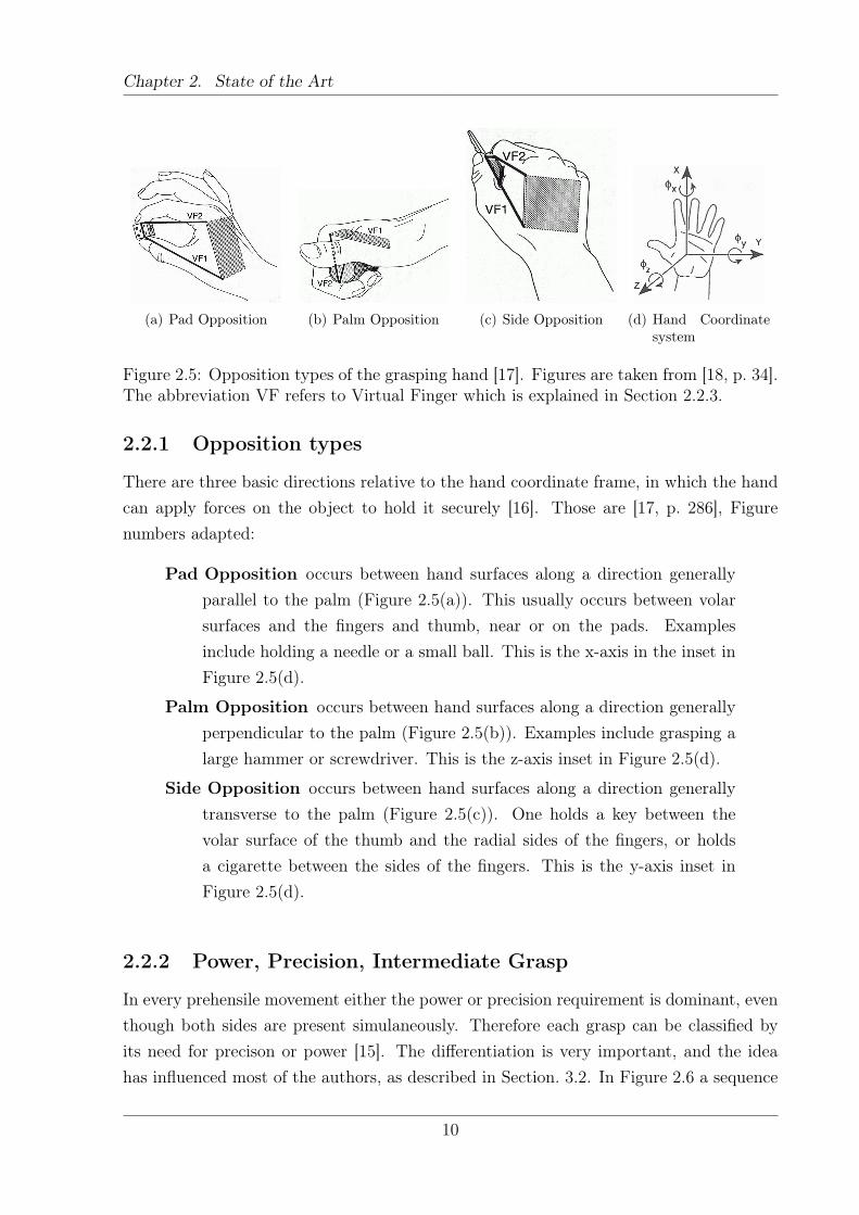
(a) Pad Opposition (b) Palm Opposition (c) Side Opposition (d) Hand Coordinatesystem
Figure 2.5: Opposition types of the grasping hand [17]. Figures are taken from [18, p. 34].The abbreviation VF refers to Virtual Finger which is explained in Section 2.2.3.
2.2.1 Opposition types
There are three basic directions relative to the hand coordinate frame, in which the handcan apply forces on the object to hold it securely [16]. Those are [17, p. 286], Figurenumbers adapted:
Pad Opposition occurs between hand surfaces along a direction generallyparallel to the palm (Figure 2.5(a)). This usually occurs between volarsurfaces and the fingers and thumb, near or on the pads. Examplesinclude holding a needle or a small ball. This is the x-axis in the inset inFigure 2.5(d).
Palm Opposition occurs between hand surfaces along a direction generallyperpendicular to the palm (Figure 2.5(b)). Examples include grasping alarge hammer or screwdriver. This is the z-axis inset in Figure 2.5(d).
Side Opposition occurs between hand surfaces along a direction generallytransverse to the palm (Figure 2.5(c)). One holds a key between thevolar surface of the thumb and the radial sides of the fingers, or holdsa cigarette between the sides of the fingers. This is the y-axis inset inFigure 2.5(d).
2.2.2 Power, Precision, Intermediate Grasp
In every prehensile movement either the power or precision requirement is dominant, eventhough both sides are present simulaneously. Therefore each grasp can be classified byits need for precison or power [15]. The differentiation is very important, and the ideahas influenced most of the authors, as described in Section. 3.2. In Figure 2.6 a sequence
10
Chapter 2. State of the Art
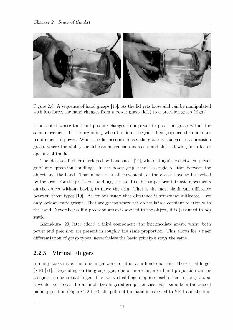
Figure 2.6: A sequence of hand grasps [15]. As the lid gets loose and can be manipulatedwith less force, the hand changes from a power grasp (left) to a precision grasp (right).
is presented where the hand posture changes from power to precision grasp within thesame movement. In the beginning, when the lid of the jar is being opened the dominantrequirement is power. When the lid becomes loose, the grasp is changed to a precisiongrasp, where the ability for delicate movements increases and thus allowing for a fasteropening of the lid.
The idea was further developed by Landsmeer [19], who distinguishes between “powergrip” and “precision handling”. In the power grip, there is a rigid relation between theobject and the hand. That means that all movements of the object have to be evokedby the arm. For the precision handling, the hand is able to perform intrinsic movementson the object without having to move the arm. That is the most significant differencebetween those types [19]. As for our study that difference is somewhat mitigated – weonly look at static grasps. That are grasps where the object is in a constant relation withthe hand. Nevertheless if a precision grasp is applied to the object, it is (assumed to be)static.
Kamakura [20] later added a third component, the intermediate grasp, where bothpower and precision are present in roughly the same proportion. This allows for a finerdifferentiation of grasp types, nevertheless the basic principle stays the same.
2.2.3 Virtual Fingers
In many tasks more than one finger work together as a functional unit, the virtual finger(VF) [21]. Depending on the grasp type, one or more finger or hand proportion can beassigned to one virtual finger. The two virtual fingers oppose each other in the grasp, asit would be the case for a simple two fingered gripper or vice. For example in the case ofpalm opposition (Figure 2.2.1 B), the palm of the hand is assigned to VF 1 and the four
11
Chapter 2. State of the Art
fingers act against it as VF 2.If one or more fingers are opposing a task related force or torque, these fingers are
assigned VF 3, otherwise VF 3 will not be assigned [17].
2.2.4 Grasp Taxonomies
A big effort has been put into categorizing the human grasp postures. As the literaturereview in Section 3 will reveal, many different classifications are available and there is noconsensus between publications. This seems to be due the fact that each publication hasa different focus and that the hand movements are so complex that classifying them isvery difficult.
2.3 Artificial Hands
2.3.1 Prosthetic Hands
In contrast to robotic hands, described in Section 2.3.2, prosthetic hands have a limitedamount of DoF. This is due to the problems a dextrous hand poses in terms of design,reliability and control. A prosthetic hand has to be rather small (human size), the actua-tors have to be integrated in the hand itself, because it has to fit to a patient which onlylost his hand and not his forearm [22]. Therefore, there is no space to locate the actuatorsof the hand on the forearm. In addition it has to be very reliable [4], as the patient willuse it everyday in a variety of different tasks. Consequently, the hand cannot be designedto fulfill a specific purpose. There are various commercial products available, as will bedescribed further in this section.
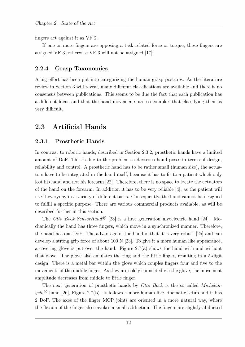
The Otto Bock SensorHand® [23] is a first generation myoelectric hand [24]. Me-chanically the hand has three fingers, which move in a synchronized manner. Therefore,the hand has one DoF. The advantage of the hand is that it is very robust [25] and candevelop a strong grip force of about 100 N [23]. To give it a more human like appearance,a covering glove is put over the hand. Figure 2.7(a) shows the hand with and withoutthat glove. The glove also emulates the ring and the little finger, resulting in a 5-digitdesign. There is a metal bar within the glove which couples fingers four and five to themovements of the middle finger. As they are solely connected via the glove, the movementamplitude decreases from middle to little finger.
The next generation of prosthetic hands by Otto Bock is the so called Michelan-gelo® hand [26], Figure 2.7(b). It follows a more human-like kinematic setup and it has2 DoF. The axes of the finger MCP joints are oriented in a more natural way, wherethe flexion of the finger also invokes a small adduction. The fingers are slightly abducted
12
Chapter 2. State of the Art
(a) Left: The Otto Bock SensorHandSpeed® without the glove. The threefingers move in a synchronous manner.Right: The prosthetic glove which cov-ers the hand and gives the hand a five-digit appearance [23].
(b) Otto Bock Michelangelo® hand [26].
Figure 2.7: Prosthetic hands by Otto Bock.
when the MCP joints of the fingers are extended, whereas when flexed the fingertips toucheach other. The first DoF is the main drive which is responsible for a coordinated flexionand extension of the five digits. The second DoF changes the thumb position – it can beabducted or adducted. That allows for two different grasp types, a tip pinch between thethumb and the index and middle finger and the lateral grasp between thumb and the sideof the index finger.
The I-Limb™ ultra Hand by Touch Bionics™ has a different kinematic setup and isshown in Figure 2.8. Every finger is actuated by one motor and the MCP and PIPjoints of the fingers are coupled. That gives the hand 5 DoF, but that causes a largecontrol problem. Therefore, the hand is controlled in the “classical” way, with one or twoelectrodes [27]. As all the fingers move simultaneously, or according to a fixed sequence,the hand control space is one-dimensional. In addition to the myoelectrically controlledfinger movements, the thumb can be manually adjusted to be in an adducted or abductedposition. The setup offers some compliance, as every finger closes independently until itis in contact with the grasped object which stops the movement.
2.3.2 Anthropomorphic Robotic Hands
Many robot hands have been developed in the past and many have had the human handas paradigm. Depending on the purpose, they have different properties regarding size,sensors, Degree of Freedom etc. Research prototypes tend to have a lot of DoF, but arerarely used outside the university environment. One exception is the Shadow Dexterous
13
Chapter 2. State of the Art
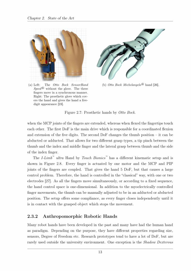
Figure 2.8: The I-Limb™ ultra hand from Touch Bionics™ without a covering glove. Thekinematic structure of the five digits is identical [28].
Figure 2.9: The kinematic setup of the Shadow Dexterous Hand C6. Each large cylinderrepresents one joint of the hand [30].
Hand C6 [29] which has 20 DoF and 24 joints. The actuators are 40 pneumatic muscles,which are situated on the forearm. The kinematic setup of the hand is shown in Figure 2.9.The index, middle and ring finger have four joints and the little finger has five joints. Theadditional joint is the movement of the CMC joint. The PIP and DIP joints of the fingersare coupled, reducing the DoF per finger to 3 and 4 respectively. The thumb has fiveDoF, two in the CMC and MCP joint, one in the IP joint. Additionally, the wrist offers2 movement possibilities, summing up to a total of 20 DoF.
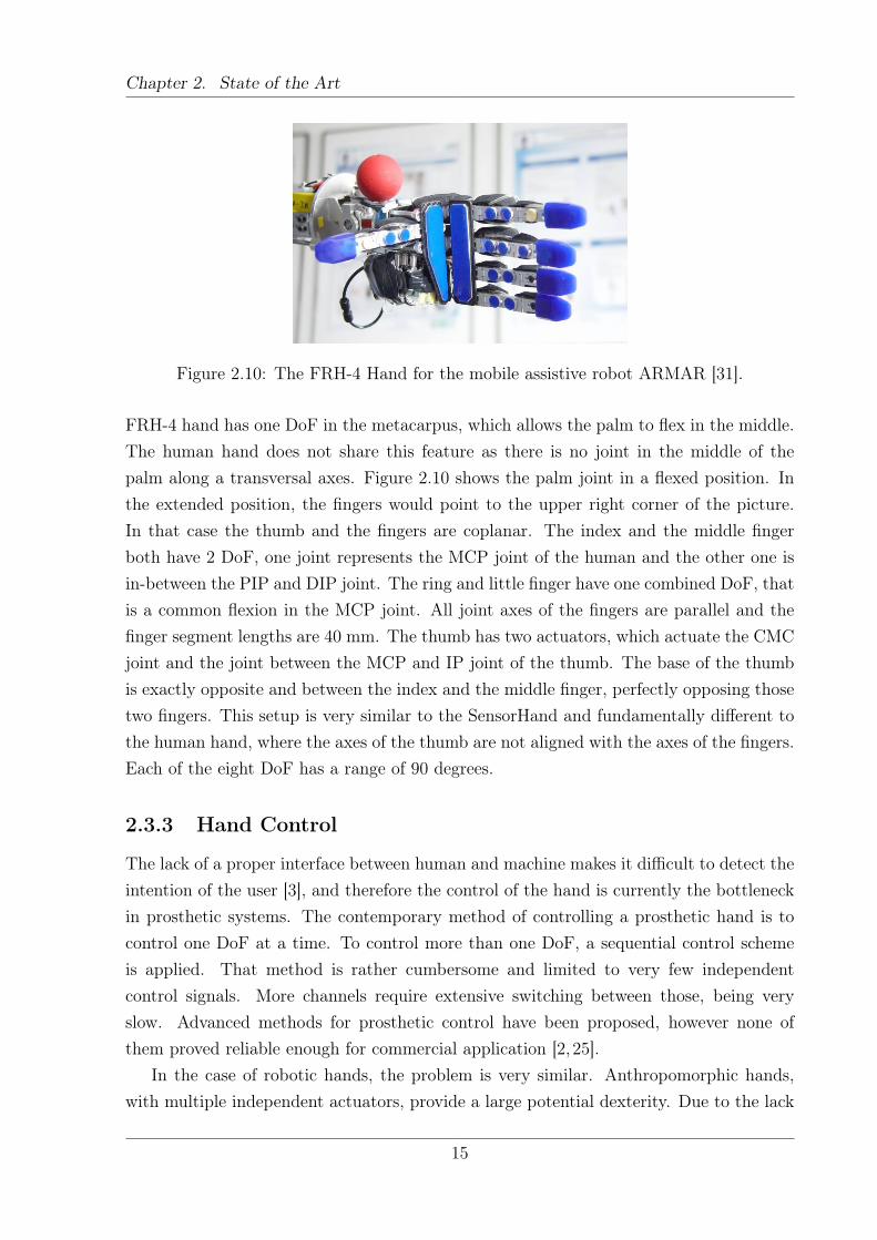
The FRH-4 hand [31] built for the mobile assistive robot ARMAR has 8 fluidic actu-ators. Its general appearance (Figure 2.10) is human-like, it has a size that is comparableto the human hand and the kinematic setup has some similarities. One design goal ofthe hand was to be anthropomorphic, but another goal was to develop a hand whichis suitable for robotic grasping. To meet the second design objective, tradeoffs on theanthropomorphism had to be accepted. One major difference is the palm setup – the
14
Chapter 2. State of the Art
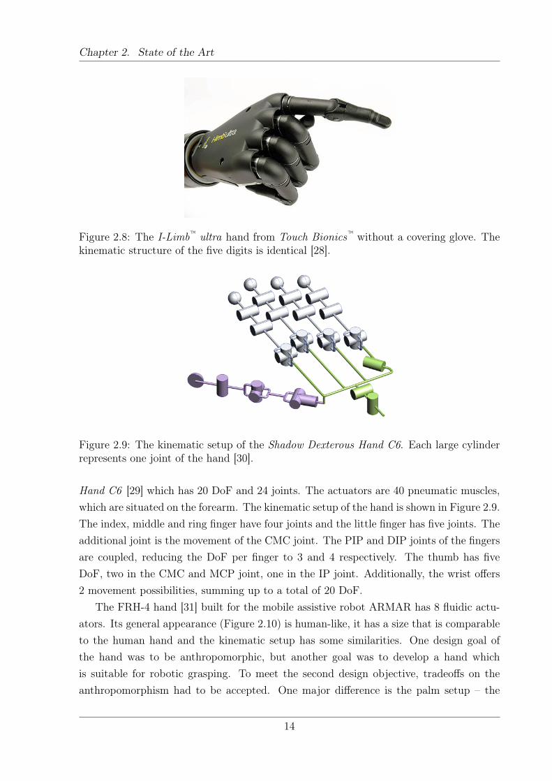
Figure 2.10: The FRH-4 Hand for the mobile assistive robot ARMAR [31].
FRH-4 hand has one DoF in the metacarpus, which allows the palm to flex in the middle.The human hand does not share this feature as there is no joint in the middle of thepalm along a transversal axes. Figure 2.10 shows the palm joint in a flexed position. Inthe extended position, the fingers would point to the upper right corner of the picture.In that case the thumb and the fingers are coplanar. The index and the middle fingerboth have 2 DoF, one joint represents the MCP joint of the human and the other one isin-between the PIP and DIP joint. The ring and little finger have one combined DoF, thatis a common flexion in the MCP joint. All joint axes of the fingers are parallel and thefinger segment lengths are 40 mm. The thumb has two actuators, which actuate the CMCjoint and the joint between the MCP and IP joint of the thumb. The base of the thumbis exactly opposite and between the index and the middle finger, perfectly opposing thosetwo fingers. This setup is very similar to the SensorHand and fundamentally different tothe human hand, where the axes of the thumb are not aligned with the axes of the fingers.Each of the eight DoF has a range of 90 degrees.
2.3.3 Hand Control
The lack of a proper interface between human and machine makes it difficult to detect theintention of the user [3], and therefore the control of the hand is currently the bottleneckin prosthetic systems. The contemporary method of controlling a prosthetic hand is tocontrol one DoF at a time. To control more than one DoF, a sequential control schemeis applied. That method is rather cumbersome and limited to very few independentcontrol signals. More channels require extensive switching between those, being veryslow. Advanced methods for prosthetic control have been proposed, however none ofthem proved reliable enough for commercial application [2, 25].
In the case of robotic hands, the problem is very similar. Anthropomorphic hands,with multiple independent actuators, provide a large potential dexterity. Due to the lack
15
Chapter 2. State of the Art
of proper control algorithms the effective dexterity is much lower, as the controller cannotmake use of the potential of the hand [1].
2.3.4 Optimal Hand Designs
Only very recently the interest has shifted to simpler hands with only a few DoF. However,they are smartly designed so that they can fulfil their assigned tasks [32]. How differentdesign parameters influence the dexterity of a kinematic hand setup is largely unknown[33] and considered a difficult task [34]. Due to the mechanical complexity of the handitself and the complex hand-object interaction it is difficult to assess the hand performancewithout realization of the design, as analytical tools are limited to few special cases.
One approach [35,36] is specialized in underactuated kinematic hand setups. Feasiblegrasping postures are manually defined for a given kinematic hand setup. This impliesthe assumption that all joints can be controlled independently. In the next step theactuation parameters resulting in the largest number of stable grasps in the predefinedpool are chosen. In that sense this is the optimal underactuated hand design. In [36] aprototype was built for a simple symmetric 2 finger gripper. For this special case it waspossible to calculate a global optimum solution. For more complex embodiments the goalfunction will become more difficult to handle, having multiple local minima and thereforecalculation will become non-trivial. Additionally, in the current implementation the setof grasps is created manually, prohibiting large scale usage.
An approach using postural synergies is presented in [37]. A certain number of in handrigid-body object motions and internal forces can be applied to the object depending onthe number of synergies (defined as basis vectors of a linear subspace) used to drive thehand. It can be shown that with an increasing number of synergies more movements andforces become controllable. For example, having three point contacts on the object andcontrolling the hand with one synergy, one internal force is controllable. Increasing thenumber of synergies up to three will render up to three internal forces controllable. Afurther increase in the number of synergies will allow for intrinsic movements. Finally, ifthe number is increased even higher redundant movements will be possible. This analysisis a good tool to judge how complex a hand has to be in order to achieve a desired degreeof dexterity. Nevertheless, this tool is limited to a linear subspace analysis and thereforeto joint couplings in a linear combination sense. Nonlinear couplings or other complexjoint coordination patterns cannot be modeled using this approach. Further, this doesnot produce hints on the actual design of a kinematic hand setup.
Using the tendon driven Anatomically Correct Testbed (ACT) hand, Malhotra andMatsuoka [38] investigate how tendon coordination patterns influence the positional pre-cision of the hand. In the fully actuated hand the only error of the controller is present,
16
Chapter 2. State of the Art
which acts as the baseline. The decrease in precision is measured after tying varioustendons to the same actuator. Without large penalties on the fingertip precision a smallreduction in actuators is possible. Controlling 20 tendons with only 16 motors results inan increase of the error of about 30 % to the fully actuated hand. When each finger isdriven only by 2 actuators, the error is twice that of the fully actuated hand.
A more specialized approach is taken in [33], where the focus is to optimize the handfor a specific set of objects with simple shape. When grasping blindly into a box ofsuch objects, the hand should be designed in such way that only a few hand-objectconfigurations are possible. Finally, the goal is that only one configuration results in asuccessful grasp. In that case no sensors would be needed to determine how the objectis grasped with the hand. The relative orientation of the object and the hand will beknown as only one configuration results in a successful grasp. The evaluation method iscomplicated and extensive as it is partly based on real experiments or complex simulations.
The experimental approach of [39] restrains different fingers and finger combinationsby tying them to a fixed structure. Then the performance of those altered human hands ismeasured with standard human hand dexterity tests (e.g. box and block test). The resultis that the thumb and the middle finger are most important for the grasping performance.The best results were obtained when the little finger was restrained, which was taken asa sign that for that simple grasps the finger did not contribute to the overall dexterity.The results are worse when the index and the middle finger are restrained.
2.4 Kinematic Chains
A kinematic chain is a series of rigid bodies connected by joints. For the thesis that is animportant concept, because a hand can be modeled as five independent kinematic chains.Each finger is represented by one chain, where the joints of the chain correspond to theactual joints of the hand. The hand models presented in the thesis are defined in thefashion introduced here.
2.4.1 Degrees of Freedom
There are different definitions for the number of Degrees of Freedom (DoF) of a systemand they depend upon the area the definition belongs to. For this thesis the followingdefinition is suitable [40, p. 133]:
“The number of degrees of freedom of a system is the number of independent variablesthat must be specified to define completely the condition of the system. In the case ofkinematic chains, it is the number F of independent pair variables needed to completelydefine the relative positions of all links.”
17
Chapter 2. State of the Art
A rigid body in a 3D space has 6 DoF - three for translation and three for rotation.The specification of position and rotation in one parameter set will be referred to as pose.
Given a kinematic chain where all joints are actuated independently, the DoF willbe equal to the number of joints. For the thesis, being in accordance with the DenavitHartenberg view of modeling kinematic chains, each joint is represented by one axis aboutwhich the rotation takes place. Accordingly, a spherical joint is modeled as three jointswhere the joint axes intersect in the center of the joint. Additionally, the six DoF whichdefine the pose in space are disregarded as the global orientation and position of the handis not of interest for the study.
If constraints on the movement are introduced, the number of DoF is reduced. Thereduction in DoF depends on the constraints’ type. For example, if the body is constraintto planar motion, the movements are restricted to 2D. In that case the body has 3 DoF –two for translation and one for rotation about the axis perpendicular to the plane. If twojoints of the kinematic chain are coupled, the DoF are reduced by one. That is due to thefact that one parameter will define the rotation of both joints and is therefore sufficient.
Care has to be taken when talking about Degrees of Freedom in human hand models.Often the specification of DoF is not correct and corresponds to the number of joints. Assome of the joints might be driven by the same actuator, a coupling between the joints isintroduced. From a mechanical perspective the number of actuators corresponds to thenumber of degrees of freedom. That discrepancy between joints and DoF can even increaseif the hand has mechanically multiple DoF, but they are all controlled in synchronization.That leads to a hand with a large number of joints, but with a small number of DoF.
The same principle applies to the human hand. Depending on the publication, around23 (with a range of 21-31) joint movements can be identified. The first assumption wouldbe that the hand has as many DoF as joints. The fact is that, due to mechanical andneural limitations, the joints of the hand are coupled to some degree. Consequently, not alljoints can be moved in total isolation without invoking a movement in other joints. In thehigh dimensional joint space, a manifold exists where the actual human hand movementstake place. The minimal dimension with which the manifold can be described will beequal to the DoF of the hand. Those couplings are non-obvious and cannot be modeledexplicitly. Therefore, data driven approaches are used to determine the dimensionality ofthe human hand. Various studies have shown that with only a few basis vectors most ofthe hand movements can be described with sufficient precision (see Section 2.5.1). Thatreveals that the actual number of Degrees of Freedom is much smaller than the numberof joints. That fact is also exploited later in the thesis, as this is the justification for thedimensionality reduction applied to the human grasping dataset.
18
Chapter 2. State of the Art
2.4.2 Denavit - Hartenberg Formalism
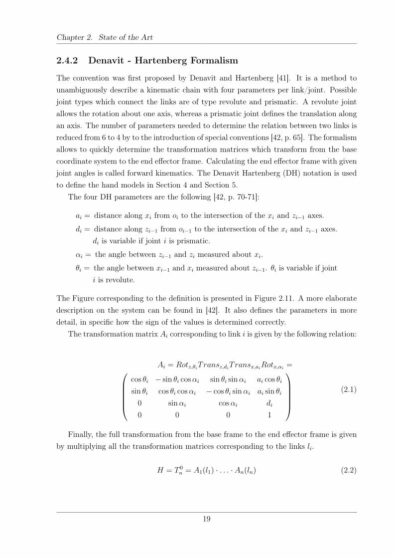
The convention was first proposed by Denavit and Hartenberg [41]. It is a method tounambiguously describe a kinematic chain with four parameters per link/joint. Possiblejoint types which connect the links are of type revolute and prismatic. A revolute jointallows the rotation about one axis, whereas a prismatic joint defines the translation alongan axis. The number of parameters needed to determine the relation between two links isreduced from 6 to 4 by to the introduction of special conventions [42, p. 65]. The formalismallows to quickly determine the transformation matrices which transform from the basecoordinate system to the end effector frame. Calculating the end effector frame with givenjoint angles is called forward kinematics. The Denavit Hartenberg (DH) notation is usedto define the hand models in Section 4 and Section 5.
The four DH parameters are the following [42, p. 70-71]:
ai = distance along xi from oi to the intersection of the xi and zi−1 axes.
di = distance along zi−1 from oi−1 to the intersection of the xi and zi−1 axes.di is variable if joint i is prismatic.
αi = the angle between zi−1 and zi measured about xi.
θi = the angle between xi−1 and xi measured about zi−1. θi is variable if jointi is revolute.
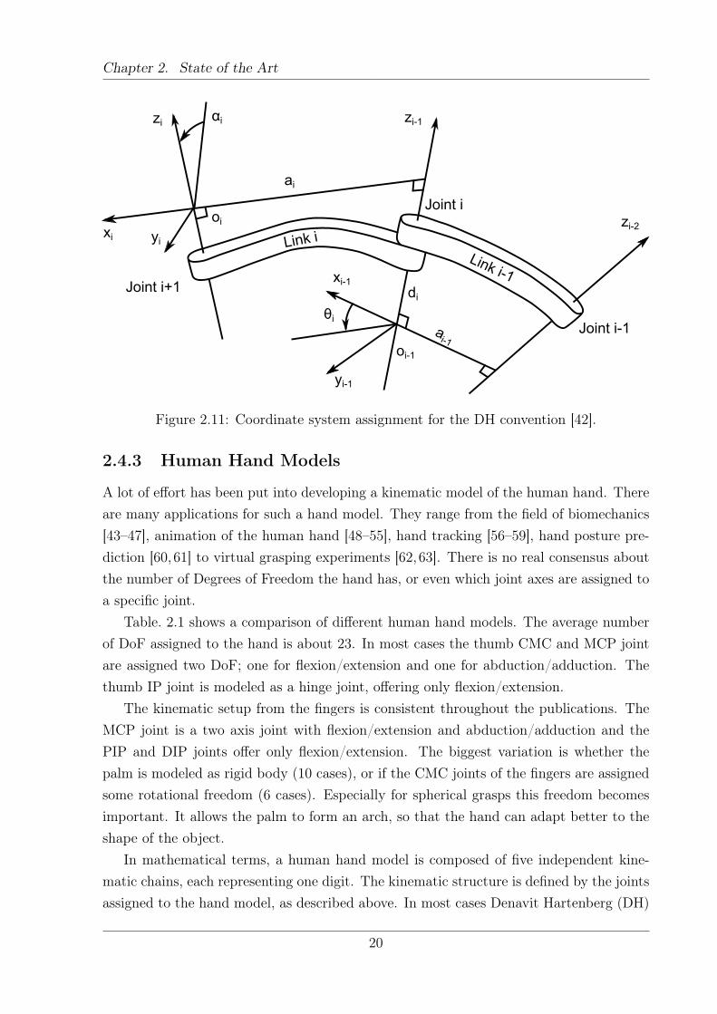
The Figure corresponding to the definition is presented in Figure 2.11. A more elaboratedescription on the system can be found in [42]. It also defines the parameters in moredetail, in specific how the sign of the values is determined correctly.
The transformation matrix Ai corresponding to link i is given by the following relation:
Ai = Rotz,θiTransz,diTransx,aiRotx,αi =cos θi − sin θi cosαi sin θi sinαi ai cos θi
sin θi cos θi cosαi − cos θi sinαi ai sin θi
0 sinαi cosαi di
0 0 0 1
(2.1)
Finally, the full transformation from the base frame to the end effector frame is givenby multiplying all the transformation matrices corresponding to the links li.
H = T 0n = A1(l1) · . . . · An(ln) (2.2)
19
Chapter 2. State of the Art
Joint i+1
xi yi
zi αi
oi
ai
Link i
zi-1
Link i-1
zi-2
Joint i-1ai-1
oi-1
di
xi-1
θi
yi-1
Joint i
Figure 2.11: Coordinate system assignment for the DH convention [42].
2.4.3 Human Hand Models
A lot of effort has been put into developing a kinematic model of the human hand. Thereare many applications for such a hand model. They range from the field of biomechanics[43–47], animation of the human hand [48–55], hand tracking [56–59], hand posture pre-diction [60, 61] to virtual grasping experiments [62, 63]. There is no real consensus aboutthe number of Degrees of Freedom the hand has, or even which joint axes are assigned toa specific joint.
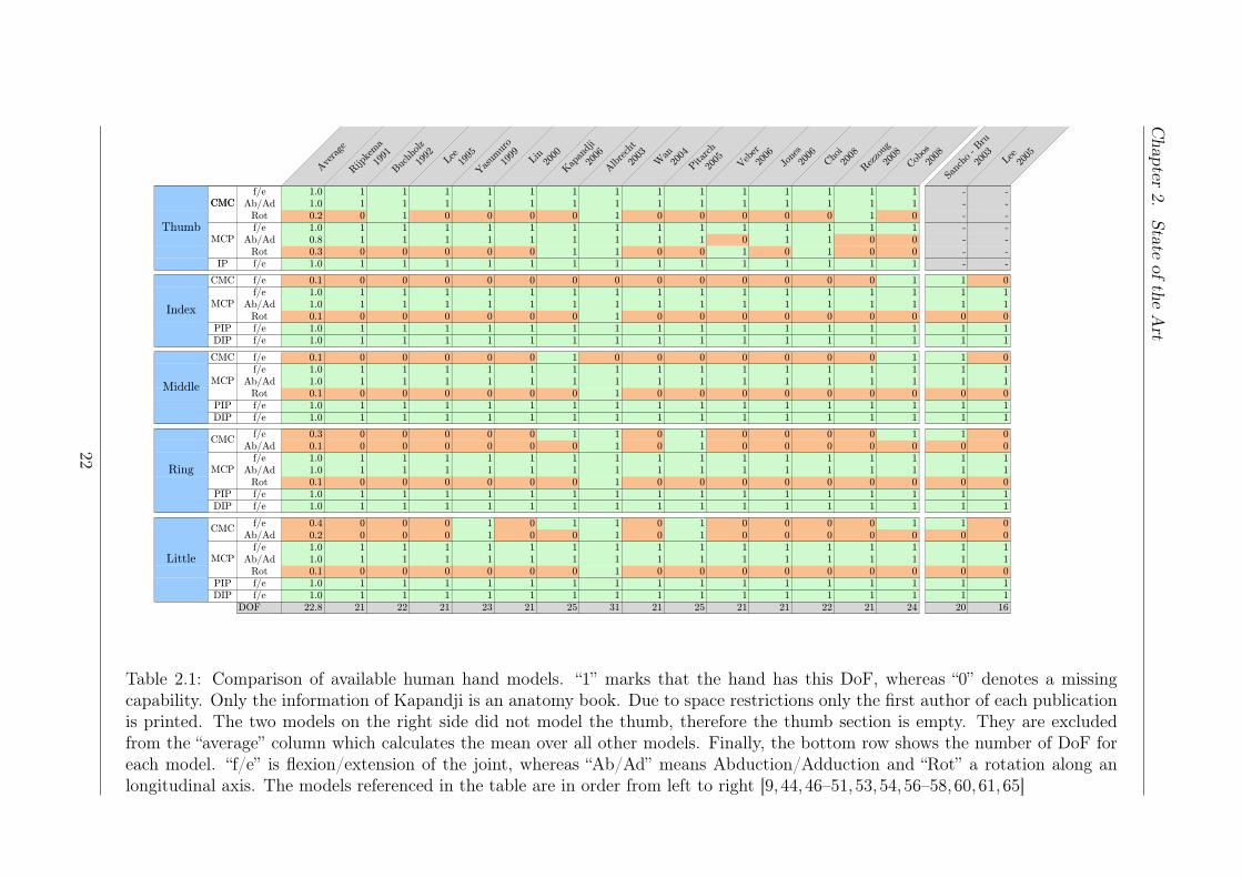
Table. 2.1 shows a comparison of different human hand models. The average numberof DoF assigned to the hand is about 23. In most cases the thumb CMC and MCP jointare assigned two DoF; one for flexion/extension and one for abduction/adduction. Thethumb IP joint is modeled as a hinge joint, offering only flexion/extension.
The kinematic setup from the fingers is consistent throughout the publications. TheMCP joint is a two axis joint with flexion/extension and abduction/adduction and thePIP and DIP joints offer only flexion/extension. The biggest variation is whether thepalm is modeled as rigid body (10 cases), or if the CMC joints of the fingers are assignedsome rotational freedom (6 cases). Especially for spherical grasps this freedom becomesimportant. It allows the palm to form an arch, so that the hand can adapt better to theshape of the object.
In mathematical terms, a human hand model is composed of five independent kine-matic chains, each representing one digit. The kinematic structure is defined by the jointsassigned to the hand model, as described above. In most cases Denavit Hartenberg (DH)
20
Chapter 2. State of the Art
parameters are used to calculate the forwards kinematics. To define such a model, manyparameters have to be determined:
• The pose of the bases of digits in the hand coordinate frame. That specifies howthe starting point of the kinematic chain is translated and rotated in space.
• The kinematic setup of the hand. The position and orientation of the joint axes andthe segment lengths have to be specified. Those parameters can be represented ina structured way with the DH convention.
• Range of motion of the joints.
• Optional: Coupling functions which connect joints and reduce the number of DoFof the hand.
Determining those parameters is not trivial. Most models generate those parametersby measuring one hand only. For example a Computed Tomography (CT) scan of ahuman hand can be used to determine the parameters [52]. A different approach is touse a system based on optical surface markers to determine the rotational centers of thehuman hand joints [64]. Unfortunately, such a system has never been used to performa large scale analysis on several specimen. To the best knowledge of the author, theonly publication which measures anthropomorphic parameters and expresses them as afunction of hand width and hand length is [44]. The kinematic parameters of cadaverhands were measured and means to scale them according to the hand length and widthare presented. As this study is composed of only six hands, it might not represent thecomplete human population.
21
Chapter
2.State
oftheArt
Ave
rage
Rijp
kem
a19
91B
uchh
olz
1992
Lee
1995
Yas
umur
o19
99
Lin
2000
Kap
andj
i20
06A
lbre
cht
2003
Wan
2004
Pit
arch
2005
Veb
er20
06
Jone
s20
06
Cho
i20
08R
ezzo
ug20
08
Cob
os20
08Sa
ncho
- B
ru20
03
Lee
2005
Thumb
CMCf/e 1.0 1 1 1 1 1 1 1 1 1 1 1 1 1 1 - -
Ab/Ad 1.0 1 1 1 1 1 1 1 1 1 1 1 1 1 1 - -
Rot 0.2 0 1 0 0 0 0 1 0 0 0 0 0 1 0 - -
f/e 1.0 1 1 1 1 1 1 1 1 1 1 1 1 1 1 - -
Ab/Ad 0.8 1 1 1 1 1 1 1 1 1 0 1 1 0 0 - -
Rot 0.3 0 0 0 0 0 1 1 0 0 1 0 1 0 0 - -
IP f/e 1.0 1 1 1 1 1 1 1 1 1 1 1 1 1 1 - -
CMC f/e 0.1 0 0 0 0 0 0 0 0 0 0 0 0 0 1 1 0
f/e 1.0 1 1 1 1 1 1 1 1 1 1 1 1 1 1 1 1
Ab/Ad 1.0 1 1 1 1 1 1 1 1 1 1 1 1 1 1 1 1
Rot 0.1 0 0 0 0 0 0 1 0 0 0 0 0 0 0 0 0
PIP f/e 1.0 1 1 1 1 1 1 1 1 1 1 1 1 1 1 1 1
DIP f/e 1.0 1 1 1 1 1 1 1 1 1 1 1 1 1 1 1 1
CMC f/e 0.1 0 0 0 0 0 1 0 0 0 0 0 0 0 1 1 0
f/e 1.0 1 1 1 1 1 1 1 1 1 1 1 1 1 1 1 1
Ab/Ad 1.0 1 1 1 1 1 1 1 1 1 1 1 1 1 1 1 1
Rot 0.1 0 0 0 0 0 0 1 0 0 0 0 0 0 0 0 0
PIP f/e 1.0 1 1 1 1 1 1 1 1 1 1 1 1 1 1 1 1
DIP f/e 1.0 1 1 1 1 1 1 1 1 1 1 1 1 1 1 1 1
f/e 0.3 0 0 0 0 0 1 1 0 1 0 0 0 0 1 1 0
Ab/Ad 0.1 0 0 0 0 0 0 1 0 1 0 0 0 0 0 0 0
f/e 1.0 1 1 1 1 1 1 1 1 1 1 1 1 1 1 1 1
Ab/Ad 1.0 1 1 1 1 1 1 1 1 1 1 1 1 1 1 1 1
Rot 0.1 0 0 0 0 0 0 1 0 0 0 0 0 0 0 0 0
PIP f/e 1.0 1 1 1 1 1 1 1 1 1 1 1 1 1 1 1 1
DIP f/e 1.0 1 1 1 1 1 1 1 1 1 1 1 1 1 1 1 1
f/e 0.4 0 0 0 1 0 1 1 0 1 0 0 0 0 1 1 0
Ab/Ad 0.2 0 0 0 1 0 0 1 0 1 0 0 0 0 0 0 0
f/e 1.0 1 1 1 1 1 1 1 1 1 1 1 1 1 1 1 1
Ab/Ad 1.0 1 1 1 1 1 1 1 1 1 1 1 1 1 1 1 1
Rot 0.1 0 0 0 0 0 0 1 0 0 0 0 0 0 0 0 0
PIP f/e 1.0 1 1 1 1 1 1 1 1 1 1 1 1 1 1 1 1
DIP f/e 1.0 1 1 1 1 1 1 1 1 1 1 1 1 1 1 1 1
DOF 22.8 21 22 21 23 21 25 31 21 25 21 21 22 21 24 20 16
CMC
MCP
Middle
Little
Index
ThumbMCP
MCP
MCP
CMC
Ring
CMC
MCP
Table 2.1: Comparison of available human hand models. “1” marks that the hand has this DoF, whereas “0” denotes a missingcapability. Only the information of Kapandji is an anatomy book. Due to space restrictions only the first author of each publicationis printed. The two models on the right side did not model the thumb, therefore the thumb section is empty. They are excludedfrom the “average” column which calculates the mean over all other models. Finally, the bottom row shows the number of DoF foreach model. “f/e” is flexion/extension of the joint, whereas “Ab/Ad” means Abduction/Adduction and “Rot” a rotation along anlongitudinal axis. The models referenced in the table are in order from left to right [9, 44,46–51,53,54,56–58,60,61,65]
22
Chapter 2. State of the Art
2.5 Unsupervised Machine Learning
The term unsupervised machine learning refers to a method to find hidden structurewithin data. The data is unlabeled, thus there is no information on specific classes adata point belongs to which can be used to define an error function. One method, tofind structure within the data is to apply dimensionality reduction algorithms in order torepresent the data in a lower dimensional space. Such a low dimensional space is referredto as latent space. The shape of such a space might deliver deeper insights into thestructure of the data. Such an approach is in particular useful if dimensions of the inputspace are coupled, thus reducing the intrinsic dimensionality of the dataset.
Due to neural and anatomical limitations, humans cannot move their finger jointsindependently. There is a large degree of interconnection between joints of the same andother digits. The thumb is the digit with the highest independence, followed by the indexfinger [11–13]. Nevertheless most joints cannot be moved in an isolated manner, be itintra- or interdigital movements. This fact reduces the intrinsic dimensionality of thehuman hand movements. If all joint axes could be moved completely independent, thenumber of DoF would be equal to the number of joint axes. As human finger movementsare coupled, certain regions in the high dimensional space simply cannot be reached.Consequently, a subspace exists within the high dimensional space where the actual humanhand movements are situated. The shape of the subspace or manifold is unknown, thus itis referred to as the latent (hidden) space. The dimension of the latent space will alwaysbe lower or equal than the dimension of the space which parameterizes the human handpostures. Various Dimensionality Reduction (DR) algorithms can be applied to find sucha latent or low dimensional embedding suitable for a given task. Most research was donewith Principal Component Analysis (PCA), but there are also other algorithms which canbe applied for that purpose. [66]
2.5.1 Principal Components Analysis
The most prominent and widely used method for dimensionality reduction is PrincipalComponent Analysis (PCA). This algorithm seeks a linear subspace which retains mostof the variance in the dataset [67]. It has been applied in a wide spectrum of researchareas [13,68–71] and the principle behind it is simple but powerful.
Theory
The data matrix Y stores N observations in each row, with D variables. Therefore, thecomplete matrix is Y ∈ RN×D. The data matrix will then be centered, so that the meanof each column is zero [72]. Additionally to centering the data should also be scaled. This
23
Chapter 2. State of the Art
can be done either by dividing each dimension by its variance or its maximum. This stepgives each dimension a similar variance, thus each dimension is treated equally. Generallyspeaking, the scaling determines the relative importance of one variable in respect tothe others. A priory knowledge can be incorporated into the system by weighting thedimensions of the high dimensional space differently.
To retain the Principal Components (PCs) the following eigenproblem has to be solved[73], where cov(Y) is the covariance matrix of Y and ui is the i-th eigenvector with acorresponding eigenvalue of λi.
cov(Y)ui = λiui (2.3)
The eigenvectors are then sorted by the value of their corresponding eigenvalues λi.The eigenvector with the highest eigenvalue is the most important one as it shows thedirection in the data with maximal variance. The second eigenvector is perpendicularto the first one, pointing into the direction with the largest remaining variance. So thefirst q eigenvectors span a linear subspace in the original space with a dimension of q. Toproject the data to a subspace, the following mapping can be applied, where M ∈ RD×q
is the mapping corresponding to the linear mapping of the first q eigenvalues. X ∈ RN×q
is the data matrix containing the low dimensional locations of the points and is obtainedby
X = (Y −Y)M. (2.4)
Each row of the matrix Y contains the means of the D variables. The rows arerepeated N times to form a N ×D matrix. That step guarantees that the mean of eachdimension is zero.
The number of PCs which should be used depends on the intrinsic dimensionality ofthe dataset and the desired level of accuracy. When the subspace is linear, or close tolinear, the method is guaranteed to find the correct subspace. On the other hand, whenthe data lies on some nonlinear manifold, PCA might have troubles finding a propersubspace, as it only looks for linear variance in the data [74].
Application to Grasping
Principal Component Analysis (PCA) can be used to gain deeper insights into the humangrasping movements [68]. Subjects are asked to imagine to grasp an object and a Cyber-glove is used to record the hand postures. Those preshapes are measured for a large set ofdifferent objects. The analysis showed that the first few PCs accounted for the vast ma-jority of variance in the dataset. On average the first three PCs accounted for about 90 %
24
Chapter 2. State of the Art
of the variance in the dataset. There are differences in literature about the actual numberof Principal Components that account for 90 % of the variance but that can be explaineddue to different measurement setups and dimensionality of the data spaces. When onlyfour fingers are taken into account and simple movements are performed, the first PC isdominant. In that case it alone contributes about 90 % of the variance [71]. This seemsto be due to the stronger coupling between the fingers and the reduced dimensionality ofthe space, as the data of the thumb is missing. Similarly, when only a few specific tasksare recorded using a 15 Degree of Freedom Cyberglove, only four PCs are needed to reachthe 90 % threshold [70]. When the hand is employed in an every day situation, composedof a variety of different hand movements, the hand movements are of higher dimension.In that case therefore 8 PCs are needed to explain 90 % of the variance [13].
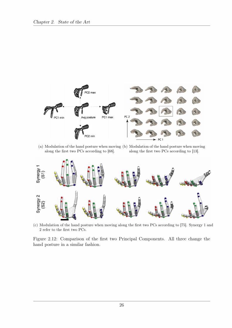
Given different datasets which consist of a larger set of human grasping movements(not restricted to specific grasp types), the first two PCs are very similar [13, 68, 75].Figure 2.12 presents a comparison of different literature sources. Commonly, the firstone is a coupled opening and closing of the full hand. It employs mostly the Metacarpaljoints of the fingers and the Carpo-Metacarpal joint of the thumb. The other joints stayin a rather moderate flexion throughout the complete movement. The second PrincipalComponent modulates primarily the bending of the fingers, especially of the index finger.Nevertheless this component shows more variation than the first. Higher PCs will prob-ably be unstable. However, the fact that the first two PCs are very similar suggests thatthere is a common 2D subspace for all human hand movements.
Eigengrasps
The term eigengrasp refers to a basis vector of a linear subspace in the joint space [63].That low-dimensional basis of grasp postures is positioned in such a way that movingwithin that subspace will cover the most important part of the hand shapes. The advan-tage is that only a few control signals are needed to control a complex hand with manyDoF. Such an eigengrasp space is commonly obtained by PCA, thus the first PCs formthe eigengrasps.
The eigengrasp concept can be applied to a grasp planning system [35, 63]. The firsttwo Principal Components are used to define the hand preshape for grasping an object.This restricts the space very much and therefore simplifies the search process for a suitablehand preshape for grasping. The system searches in the low dimensional space for apreshape which matches the presented object the best. When this shape is found, thesystem closes all fingers in a synchronized manner, until the finger movement is stoppedby a contact with the object. When the hand is closed, it has to leave the subspace,to find a hand posture which can conform with the object. An additional advantage of
25
Chapter 2. State of the Art
(a) Modulation of the hand posture when movingalong the first two PCs according to [68].
(b) Modulation of the hand posture when movingalong the first two PCs according to [13].
(c) Modulation of the hand posture when moving along the first two PCs according to [75]. Synergy 1 and2 refer to the first two PCs.
Figure 2.12: Comparison of the first two Principal Components. All three change thehand posture in a similar fashion.
26
Chapter 2. State of the Art
the system is that the planner is independent of the hand design. Simply the first twoPCs have to be specified in the embodiment specific hand space. The system itself iscompletely independent of the hand kinematics. Up to now the focus has been provingthe applicability of the system. Determining the optimal linear subspace for a given taskhas never been done.
2.5.2 Isomap
Isomap is a nonlinear method for dimensionality reduction [74]. The algorithm tries topreserve the pairwise geodesic distance between points, which is the distance measured onthe lowdimensional manifold. As an approximation of the true distance, it is calculatedby finding the shortest path between neighboring data points. The distance between allpoints is calculated and this information is fed to the Multi Dimensional Scaling algorithmwhich calculates the low dimensional representation of the data. A major weakness is thetopological instability of the algorithm [76]. If the data is disrupted by noise, or themanifold is sparsely populated, a shortcut might occur. This means that the presumedneighboring point is not close, as it belongs to another branch and the actual distancealong the manifold would be much bigger. Such a distance is obviously wrong and corruptsthe result.
Isomap can be used to control a robotic hand [77]. A dataset with different humanhand movements (tapping, 2 power grasps and 3 precision grasps) is measured with aVicon optical marker capture system and consists of approx. 500 points. The latent spaceis constructed using Isomap. As each point in the low dimensional space corresponds toa hand posture, a simple control of a complex hand is possible. By moving a point in thetwo dimensional latent space, a robotic hand can be controlled. Nevertheless, the amountof different movements in the training dataset was limited, and therefore the hand wasnot able to perform complex movements.
2.5.3 Locally Linear Embedding
Locally Linear Embedding (LLE) is also a nonlinear dimensionality reduction algorithm[78]. In contrast to PCA and Isomap, Locally Linear Embedding is a local technique. Italso constructs a neighborhood graph, but in contrast to Isomap it only tries to recoverthe local structure of the data [76]. Each datapoint is constructed as a linear combinationof its neighbors. In the lowdimensional space LLE tries to find the weights of the linearcombinations which are most similar to the highdimensional ones. It is less sensitive toshort circuiting since only a small proportion of the data is altered if it occurs. As in thecase with Isomap, LLE is weak if a dataset contains holes or is altered by large amounts
27
Chapter 2. State of the Art
of holes [76].
2.5.4 Gaussian Process Latent Variable Models
Gaussian Process Latent Variable Model (GP-LVM) is a probabilistic generative methodfor dimensionality reduction. Recently GP-LVM and its variants have proved their use-fulness in a handful of human motion modeling applications [79–82]. They have provedsuperior to other nonlinear dimensionality reduction techniques when dealing with noiseand incomplete data [83].
Theory
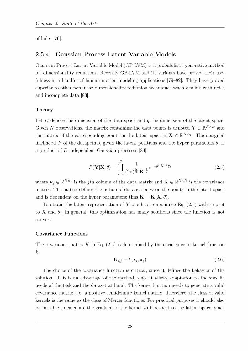
Let D denote the dimension of the data space and q the dimension of the latent space.Given N observations, the matrix containing the data points is denoted Y ∈ RN×D andthe matrix of the corresponding points in the latent space is X ∈ RN×q. The marginallikelihood P of the datapoints, given the latent positions and the hyper parameters θ, isa product of D independent Gaussian processes [84]:
P (Y|X, θ) =D∏j=1
1
(2π)N2 |K| 12
e−12yTj K
−1yj (2.5)
where yj ∈ RN×1 is the jth column of the data matrix and K ∈ RN×N is the covariancematrix. The matrix defines the notion of distance between the points in the latent spaceand is dependent on the hyper parameters; thus K = K(X, θ).
To obtain the latent representation of Y one has to maximize Eq. (2.5) with respectto X and θ. In general, this optimization has many solutions since the function is notconvex.
Covariance Functions
The covariance matrix K in Eq. (2.5) is determined by the covariance or kernel functionk:
Ki,j = k(xi,xj) (2.6)
The choice of the covariance function is critical, since it defines the behavior of thesolution. This is an advantage of the method, since it allows adaptation to the specificneeds of the task and the dataset at hand. The kernel function needs to generate a validcovariance matrix, i.e. a positive semidefinite kernel matrix. Therefore, the class of validkernels is the same as the class of Mercer functions. For practical purposes it should alsobe possible to calculate the gradient of the kernel with respect to the latent space, since
28
Chapter 2. State of the Art
gradient based optimization is used to calculate the maxima of Eq. (2.5). A special caseis the linear kernel
k(xi,xj) = αLxixj (2.7)
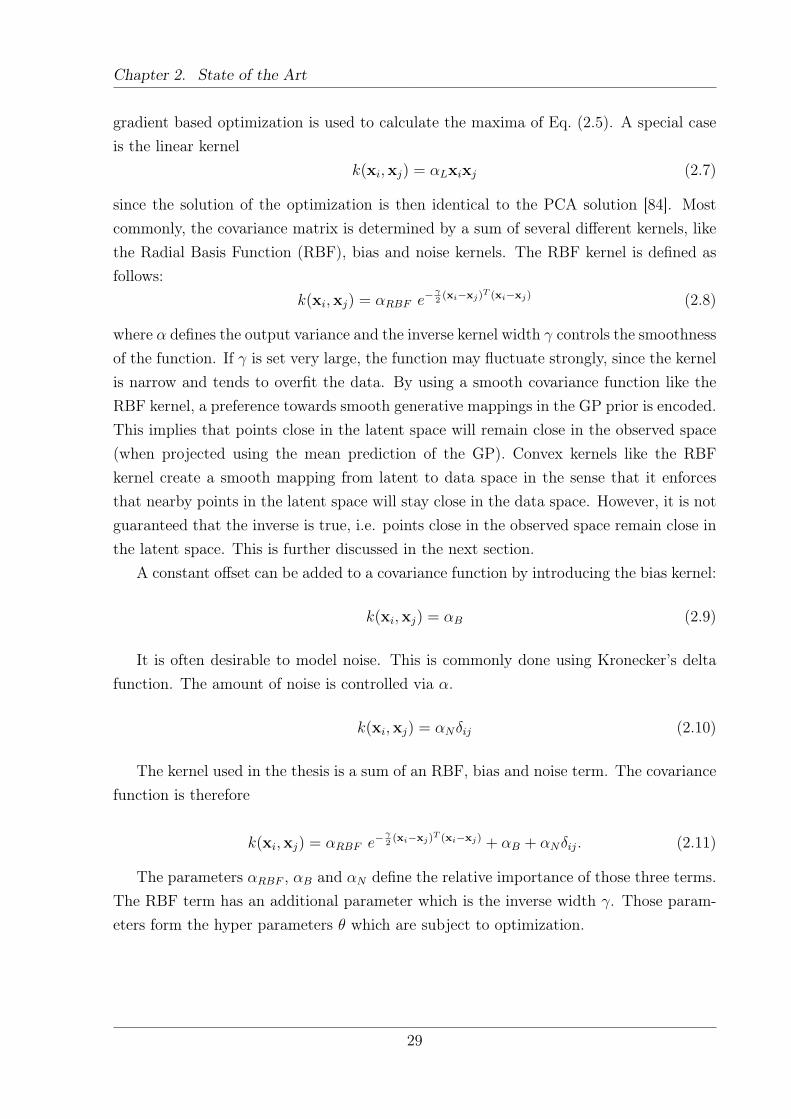
since the solution of the optimization is then identical to the PCA solution [84]. Mostcommonly, the covariance matrix is determined by a sum of several different kernels, likethe Radial Basis Function (RBF), bias and noise kernels. The RBF kernel is defined asfollows:
k(xi,xj) = αRBF e−γ2(xi−xj)T (xi−xj) (2.8)
where α defines the output variance and the inverse kernel width γ controls the smoothnessof the function. If γ is set very large, the function may fluctuate strongly, since the kernelis narrow and tends to overfit the data. By using a smooth covariance function like theRBF kernel, a preference towards smooth generative mappings in the GP prior is encoded.This implies that points close in the latent space will remain close in the observed space(when projected using the mean prediction of the GP). Convex kernels like the RBFkernel create a smooth mapping from latent to data space in the sense that it enforcesthat nearby points in the latent space will stay close in the data space. However, it is notguaranteed that the inverse is true, i.e. points close in the observed space remain close inthe latent space. This is further discussed in the next section.
A constant offset can be added to a covariance function by introducing the bias kernel:
k(xi,xj) = αB (2.9)
It is often desirable to model noise. This is commonly done using Kronecker’s deltafunction. The amount of noise is controlled via α.
k(xi,xj) = αNδij (2.10)
The kernel used in the thesis is a sum of an RBF, bias and noise term. The covariancefunction is therefore
k(xi,xj) = αRBF e−γ2(xi−xj)T (xi−xj) + αB + αNδij. (2.11)
The parameters αRBF , αB and αN define the relative importance of those three terms.The RBF term has an additional parameter which is the inverse width γ. Those param-eters form the hyper parameters θ which are subject to optimization.
29
Chapter 2. State of the Art
Back Constraints
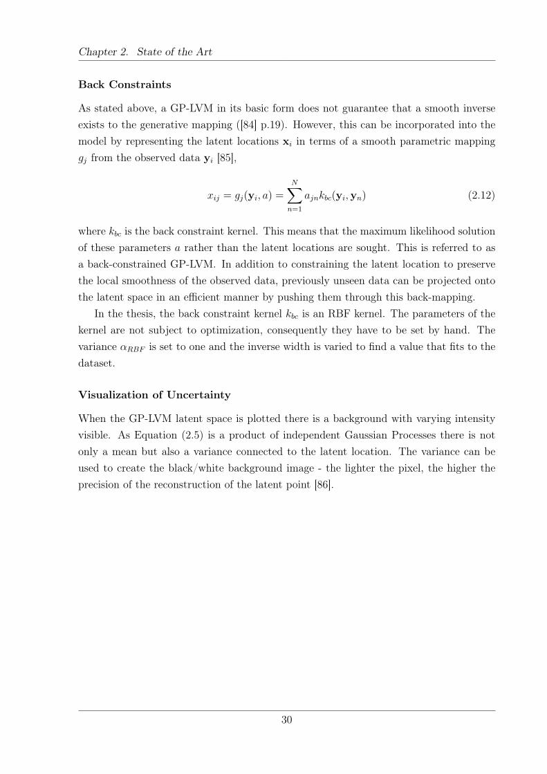
As stated above, a GP-LVM in its basic form does not guarantee that a smooth inverseexists to the generative mapping ([84] p.19). However, this can be incorporated into themodel by representing the latent locations xi in terms of a smooth parametric mappinggj from the observed data yi [85],
xij = gj(yi, a) =N∑n=1
ajnkbc(yi,yn) (2.12)
where kbc is the back constraint kernel. This means that the maximum likelihood solutionof these parameters a rather than the latent locations are sought. This is referred to asa back-constrained GP-LVM. In addition to constraining the latent location to preservethe local smoothness of the observed data, previously unseen data can be projected ontothe latent space in an efficient manner by pushing them through this back-mapping.
In the thesis, the back constraint kernel kbc is an RBF kernel. The parameters of thekernel are not subject to optimization, consequently they have to be set by hand. Thevariance αRBF is set to one and the inverse width is varied to find a value that fits to thedataset.
Visualization of Uncertainty
When the GP-LVM latent space is plotted there is a background with varying intensityvisible. As Equation (2.5) is a product of independent Gaussian Processes there is notonly a mean but also a variance connected to the latent location. The variance can beused to create the black/white background image - the lighter the pixel, the higher theprecision of the reconstruction of the latent point [86].
30
Chapter 3Comprehensive Grasp Taxonomy
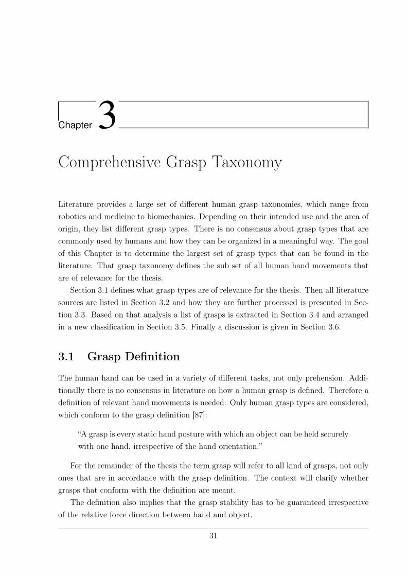
Literature provides a large set of different human grasp taxonomies, which range fromrobotics and medicine to biomechanics. Depending on their intended use and the area oforigin, they list different grasp types. There is no consensus about grasp types that arecommonly used by humans and how they can be organized in a meaningful way. The goalof this Chapter is to determine the largest set of grasp types that can be found in theliterature. That grasp taxonomy defines the sub set of all human hand movements thatare of relevance for the thesis.
Section 3.1 defines what grasp types are of relevance for the thesis. Then all literaturesources are listed in Section 3.2 and how they are further processed is presented in Sec-tion 3.3. Based on that analysis a list of grasps is extracted in Section 3.4 and arrangedin a new classification in Section 3.5. Finally a discussion is given in Section 3.6.
3.1 Grasp Definition
The human hand can be used in a variety of different tasks, not only prehension. Addi-tionally there is no consensus in literature on how a human grasp is defined. Therefore adefinition of relevant hand movements is needed. Only human grasp types are considered,which conform to the grasp definition [87]:
“A grasp is every static hand posture with which an object can be held securelywith one hand, irrespective of the hand orientation.”
For the remainder of the thesis the term grasp will refer to all kind of grasps, not onlyones that are in accordance with the grasp definition. The context will clarify whethergrasps that conform with the definition are meant.
The definition also implies that the grasp stability has to be guaranteed irrespectiveof the relative force direction between hand and object.
31
Chapter 3. Comprehensive Grasp Taxonomy
The definition rules out:
Intrinsic Movements: They are excluded because the object is not in a constant rela-tionship to the hand.
Bimanual Tasks: Only one hand is to be used.
Gravity dependent grasps: They are ruled out, because the hand orientation is vitalto the grasp stability. If one turns the hand, the object may fall down, which is notirrespective of the force direction. Grasps being excluded here are, amongst others,the Hook Grasp and the Flat Hand Grasp.
It is interesting to note that grasping a glass of water still fits into that definition.The glass is sensible to the orientation of the hand, but this is not because the graspwould lose its stability if the hand rotates. Just the water would be poured out – so theorientation of the hand is constrained by the object itself, not by the grasp stability.
3.2 Compared Taxonomies
This section gives a short overview of the literature sources taken into considerationand the intended application of the taxonomies. They will be compressed later in thecomparison sheet and based on them a new taxonomy is built (Section 3.5). The literaturesources are presented in chronological order.
3.2.1 Schlesinger
Schlesinger [88] was the first to create a classification of human hand grasps. He comes upwith six major human hand grasps, which were later summarized by Taylor and Schwarz[89]. The grasps are depicted in Figure 3.1. The Taxonomy covers a lot of different handpostures, but does not go into detail too much.
3.2.2 Slocum and Pratt
Coming from the field of rehabilitation, Slocum and Pratt [90] give an overview on handfunction and propose a system on which the amputation of parts of the hand could beassessed. In their opinion it is important to know to which degree the function of thehand is altered. It is important for the appraisal by insurance companies, and to have abasis on which medical treatment can be planned. This has to be seen in the light of theperiod of the publication; in 1946 the Second World War had just ended and there was alarge need for treatment of people with hand injuries.
In their opinion there are three fundamental hand functions [90] p. 491:
32
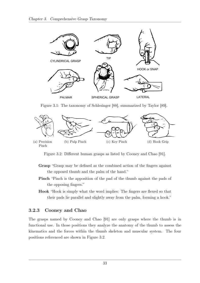
Chapter 3. Comprehensive Grasp Taxonomy
LATERAL
HOOK or SNAP
TIPCYLINDRICAL GRASP
PALMAR SPHERICAL GRASP
Figure 3.1: The taxonomy of Schlesinger [88], summarized by Taylor [89].
(a) PrecisionPinch
(b) Pulp Pinch (c) Key Pinch (d) Hook Grip
Figure 3.2: Different human grasps as listed by Cooney and Chao [91].
Grasp “Grasp may be defined as the combined action of the fingers againstthe opposed thumb and the palm of the hand.”
Pinch “Pinch is the apposition of the pad of the thumb against the pads ofthe opposing fingers.”
Hook “Hook is simply what the word implies: The fingers are flexed so thattheir pads lie parallel and slightly away from the palm, forming a hook.”
3.2.3 Cooney and Chao
The grasps named by Cooney and Chao [91] are only grasps where the thumb is infunctional use. In those positions they analyze the anatomy of the thumb to assess thekinematics and the forces within the thumb skeleton and muscular system. The fourpositions referenced are shown in Figure 3.2.
33
Chapter 3. Comprehensive Grasp Taxonomy
3.2.4 Kamakura et. al
The taxonomy created by Kamakura et. al [20] is one of most complete ones available.Humans, grasp a large set of different objects, are analyzed, comparing their static grasppostures and contact area. The assumption is that there are common grasping patternspresent in human grasping actions. According to Kamakura et. al those patterns aredependent on the shape and function of the object, the habits of the person and alsochance. Seven subjects are asked to grasp 98 common objects and pictures of the graspsare taken from different viewpoints for later analysis. Overall, 14 different grasp typesare extracted and arranged in four different categories, where a grasp was considered tobe the same when the posture of the hand as well as the contact area showed similarities:
Power Grip (Figure 3.3) Within that category, a wide area of the hand is in contactwith the object, including the palm and the volar side of the fingers.
Intermediate Grip (Figure 3.4) This group is in an intermediate position between“Power Grip” and “Precision Grip”. The palm is not included as contact area andthe flexion of the fingers is moderate.
Precision Grip (Figure 3.5) The object is held between the volar side of the fingers andthe pulp of the thumb and the flexion of the fingers is small.
Grip involving no thumb (Figure 3.6) The only representative of this group is theadduction grip, where the object is grasped between two fingers.
3.2.5 Lister
Lister [92] focuses on hand reconstruction after injury. Therefore he defines eight basicpositions which make up most of the hand maneuvers which help to assess the handfunction of a patient. Figure 3.7 shows the grasp types he found. All grasp types exceptthe “hook grip” and the “flat hand” are within our grasp definition.
3.2.6 Elliott and Connolly
Elliott and Connolly [93] focus on manipulative movements of the hand. In principlethat would put the grasps out of the scope of the analysis (see Section 3.1 for the graspdefinition). A “workaround” was used: The manipulative movements were described ashaving a starting and an end posture, and those two snapshots are presented in thepublication. Each of those postures are assumed to be a static hand posture and thatallows to fit them into the grasp definition. It is obvious that if a hand is able to graspan object and perform intrinsic manipulation, it can grasp that object with that patternin a static manner as well. The relevant hand postures are depicted in Figure 3.8.
34
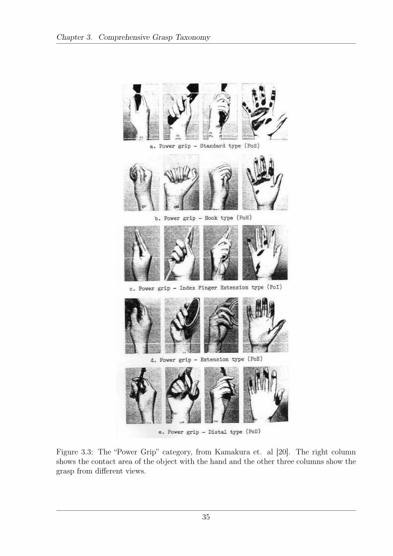
Chapter 3. Comprehensive Grasp Taxonomy
Figure 3.3: The “Power Grip” category, from Kamakura et. al [20]. The right columnshows the contact area of the object with the hand and the other three columns show thegrasp from different views.
35
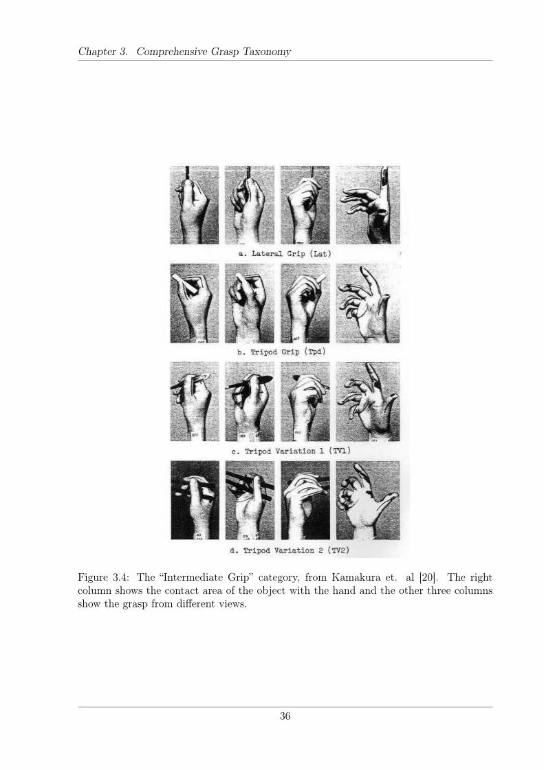
Chapter 3. Comprehensive Grasp Taxonomy
Figure 3.4: The “Intermediate Grip” category, from Kamakura et. al [20]. The rightcolumn shows the contact area of the object with the hand and the other three columnsshow the grasp from different views.
36
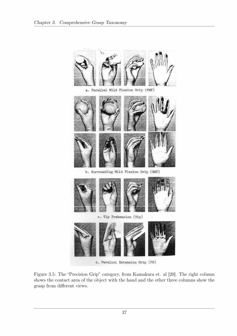
Chapter 3. Comprehensive Grasp Taxonomy
Figure 3.5: The “Precision Grip” category, from Kamakura et. al [20]. The right columnshows the contact area of the object with the hand and the other three columns show thegrasp from different views.
37
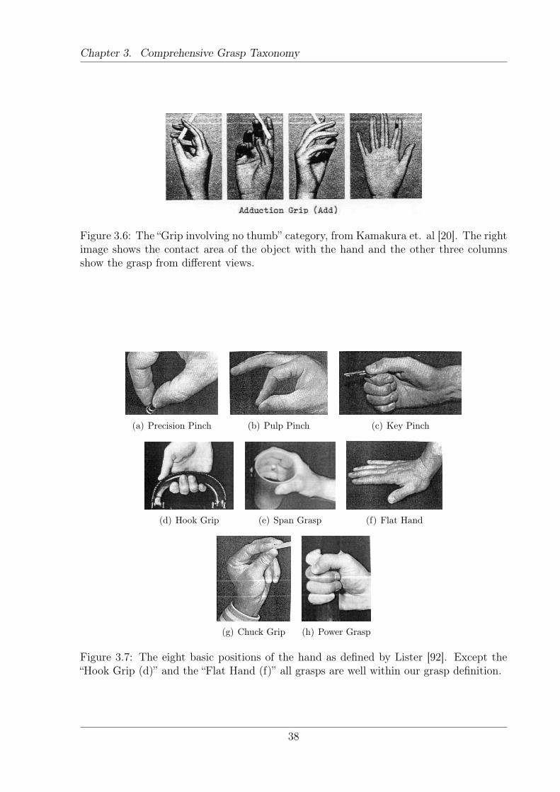
Chapter 3. Comprehensive Grasp Taxonomy
Figure 3.6: The “Grip involving no thumb” category, from Kamakura et. al [20]. The rightimage shows the contact area of the object with the hand and the other three columnsshow the grasp from different views.
(a) Precision Pinch (b) Pulp Pinch (c) Key Pinch
(d) Hook Grip (e) Span Grasp (f) Flat Hand
(g) Chuck Grip (h) Power Grasp
Figure 3.7: The eight basic positions of the hand as defined by Lister [92]. Except the“Hook Grip (d)” and the “Flat Hand (f)” all grasps are well within our grasp definition.
38
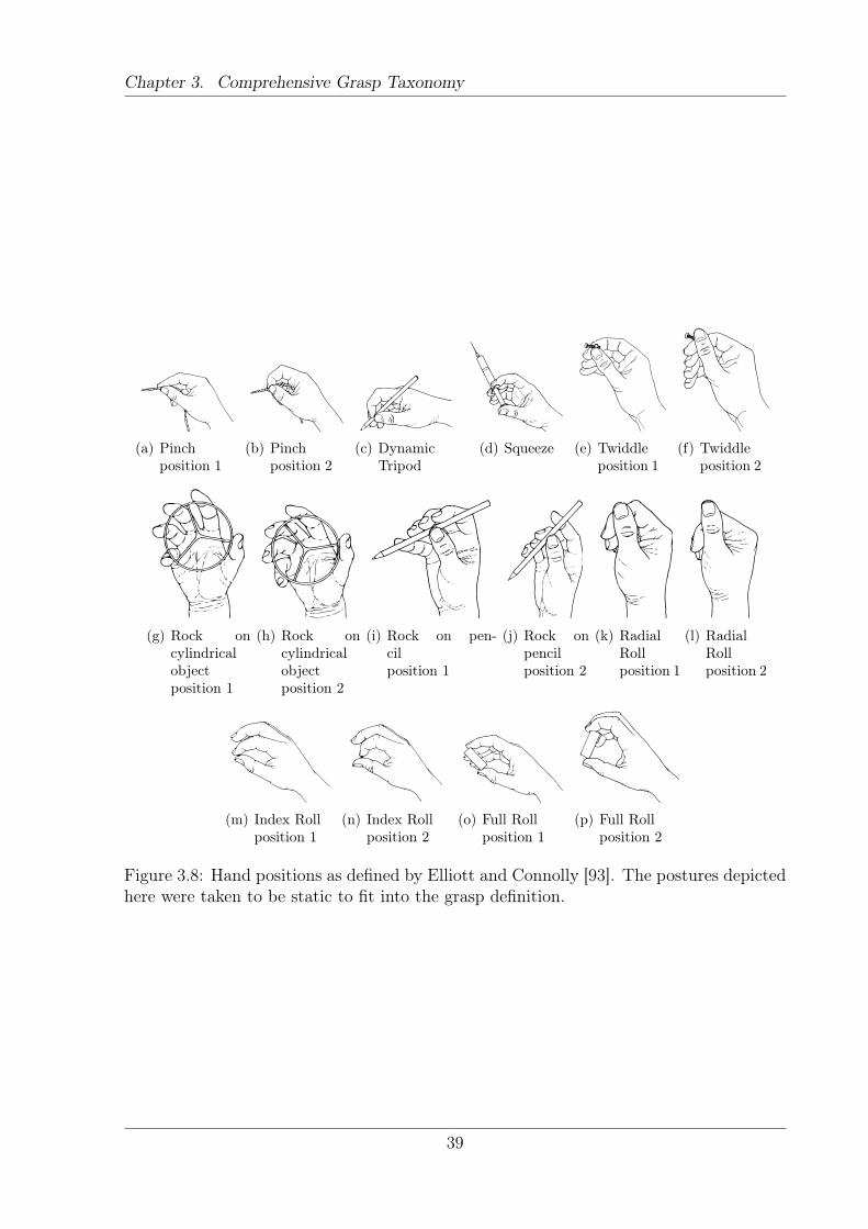
Chapter 3. Comprehensive Grasp Taxonomy
(a) Pinchposition 1
(b) Pinchposition 2
(c) DynamicTripod
(d) Squeeze (e) Twiddleposition 1
(f) Twiddleposition 2
(g) Rock oncylindricalobjectposition 1
(h) Rock oncylindricalobjectposition 2
(i) Rock on pen-cilposition 1
(j) Rock onpencilposition 2
(k) RadialRollposition 1
(l) RadialRollposition 2
(m) Index Rollposition 1
(n) Index Rollposition 2
(o) Full Rollposition 1
(p) Full Rollposition 2
Figure 3.8: Hand positions as defined by Elliott and Connolly [93]. The postures depictedhere were taken to be static to fit into the grasp definition.
39
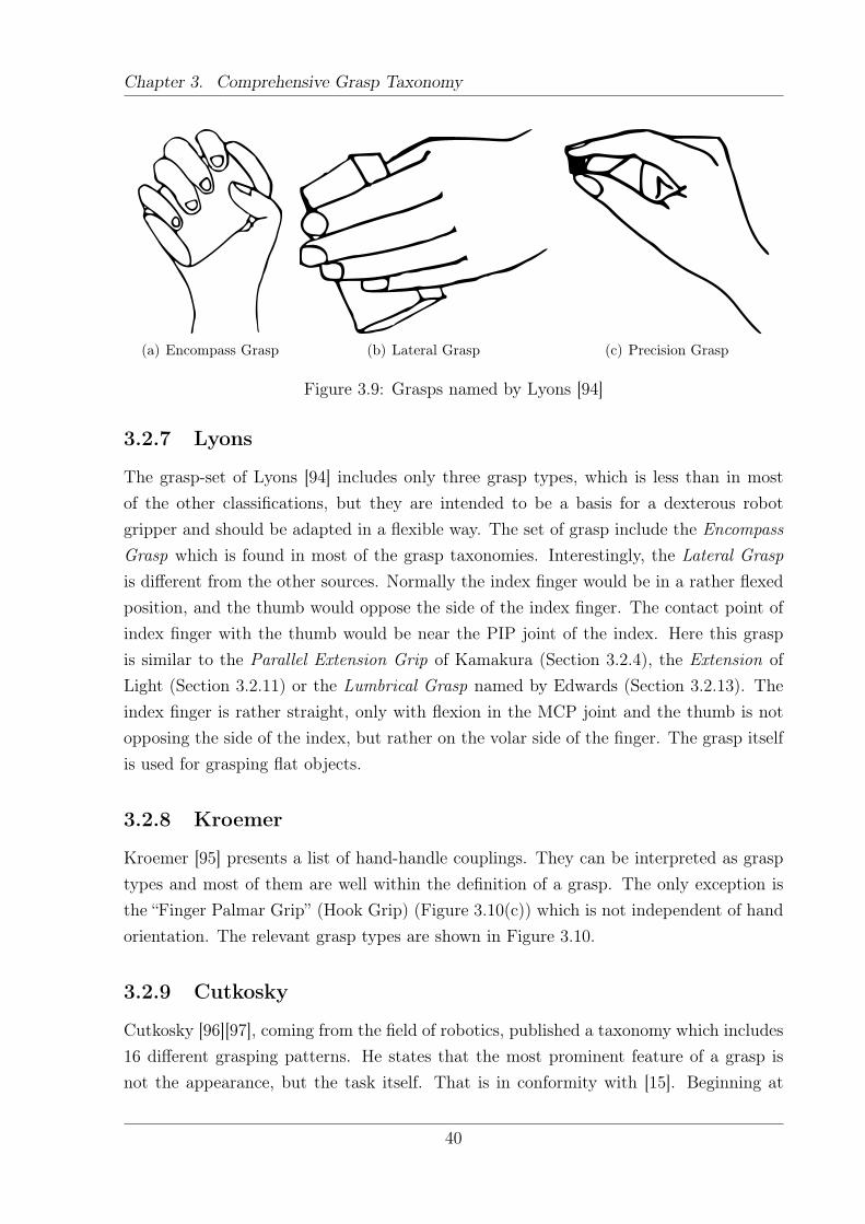
Chapter 3. Comprehensive Grasp Taxonomy
(a) Encompass Grasp (b) Lateral Grasp (c) Precision Grasp
Figure 3.9: Grasps named by Lyons [94]
3.2.7 Lyons
The grasp-set of Lyons [94] includes only three grasp types, which is less than in mostof the other classifications, but they are intended to be a basis for a dexterous robotgripper and should be adapted in a flexible way. The set of grasp include the EncompassGrasp which is found in most of the grasp taxonomies. Interestingly, the Lateral Graspis different from the other sources. Normally the index finger would be in a rather flexedposition, and the thumb would oppose the side of the index finger. The contact point ofindex finger with the thumb would be near the PIP joint of the index. Here this graspis similar to the Parallel Extension Grip of Kamakura (Section 3.2.4), the Extension ofLight (Section 3.2.11) or the Lumbrical Grasp named by Edwards (Section 3.2.13). Theindex finger is rather straight, only with flexion in the MCP joint and the thumb is notopposing the side of the index, but rather on the volar side of the finger. The grasp itselfis used for grasping flat objects.
3.2.8 Kroemer
Kroemer [95] presents a list of hand-handle couplings. They can be interpreted as grasptypes and most of them are well within the definition of a grasp. The only exception isthe “Finger Palmar Grip” (Hook Grip) (Figure 3.10(c)) which is not independent of handorientation. The relevant grasp types are shown in Figure 3.10.
3.2.9 Cutkosky
Cutkosky [96][97], coming from the field of robotics, published a taxonomy which includes16 different grasping patterns. He states that the most prominent feature of a grasp isnot the appearance, but the task itself. That is in conformity with [15]. Beginning at
40
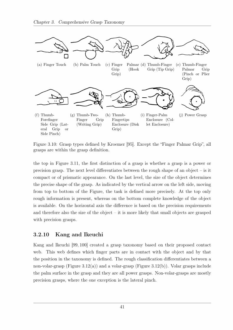
Chapter 3. Comprehensive Grasp Taxonomy
(a) Finger Touch (b) Palm Touch (c) Finger PalmarGrip (HookGrip)
(d) Thumb-FingerGrip (Tip Grip)
(e) Thumb-FingerPalmar Grip(Pinch or PlierGrip)
(f) Thumb-ForefingerSide Grip (Lat-eral Grip orSide Pinch)
(g) Thumb-Two-Finger Grip(Writing Grip)
(h) Thumb-FingertipsEnclosure (DiskGrip)
(i) Finger-PalmEnclosure (Col-let Enclosure)
(j) Power Grasp
Figure 3.10: Grasp types defined by Kroemer [95]. Except the “Finger Palmar Grip”, allgrasps are within the grasp definition.
the top in Figure 3.11, the first distinction of a grasp is whether a grasp is a power orprecision grasp. The next level differentiates between the rough shape of an object – is itcompact or of prismatic appearance. On the last level, the size of the object determinesthe precise shape of the grasp. As indicated by the vertical arrow on the left side, movingfrom top to bottom of the Figure, the task is defined more precisely. At the top onlyrough information is present, whereas on the bottom complete knowledge of the objectis available. On the horizontal axis the difference is based on the precision requirementsand therefore also the size of the object – it is more likely that small objects are graspedwith precision grasps.
3.2.10 Kang and Ikeuchi
Kang and Ikeuchi [99, 100] created a grasp taxonomy based on their proposed contactweb. This web defines which finger parts are in contact with the object and by thatthe position in the taxonomy is defined. The rough classification differentiates between anon-volar-grasp (Figure 3.12(a)) and a volar-grasp (Figure 3.12(b)). Volar grasps includethe palm surface in the grasp and they are all power grasps. Non-volar-grasps are mostlyprecision grasps, where the one exception is the lateral pinch.
41
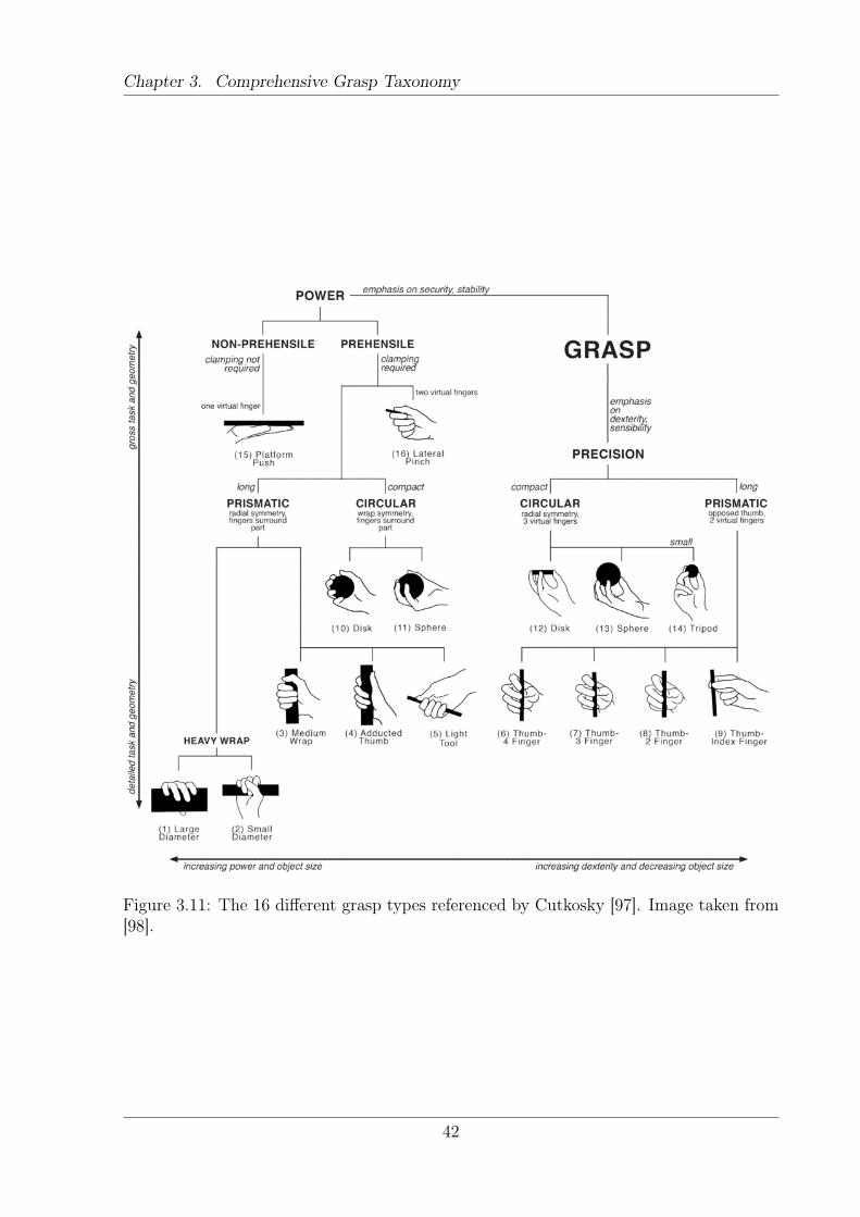
Chapter 3. Comprehensive Grasp Taxonomy
Figure 3.11: The 16 different grasp types referenced by Cutkosky [97]. Image taken from[98].
42
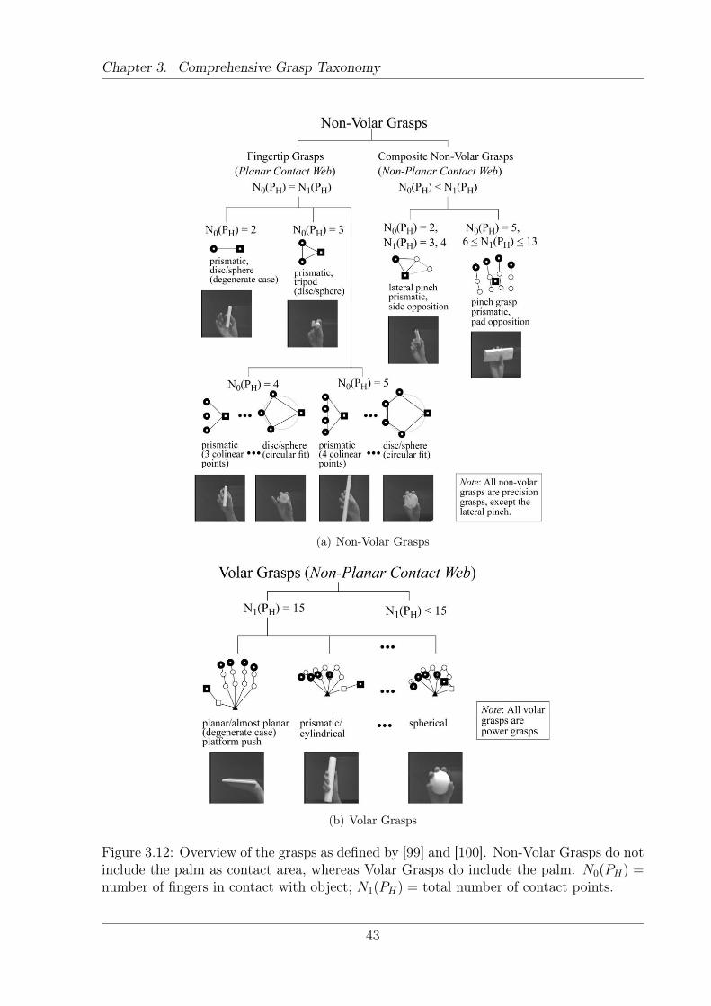
Chapter 3. Comprehensive Grasp Taxonomy
(a) Non-Volar Grasps
(b) Volar Grasps
Figure 3.12: Overview of the grasps as defined by [99] and [100]. Non-Volar Grasps do notinclude the palm as contact area, whereas Volar Grasps do include the palm. N0(PH) =number of fingers in contact with object; N1(PH) = total number of contact points.
43
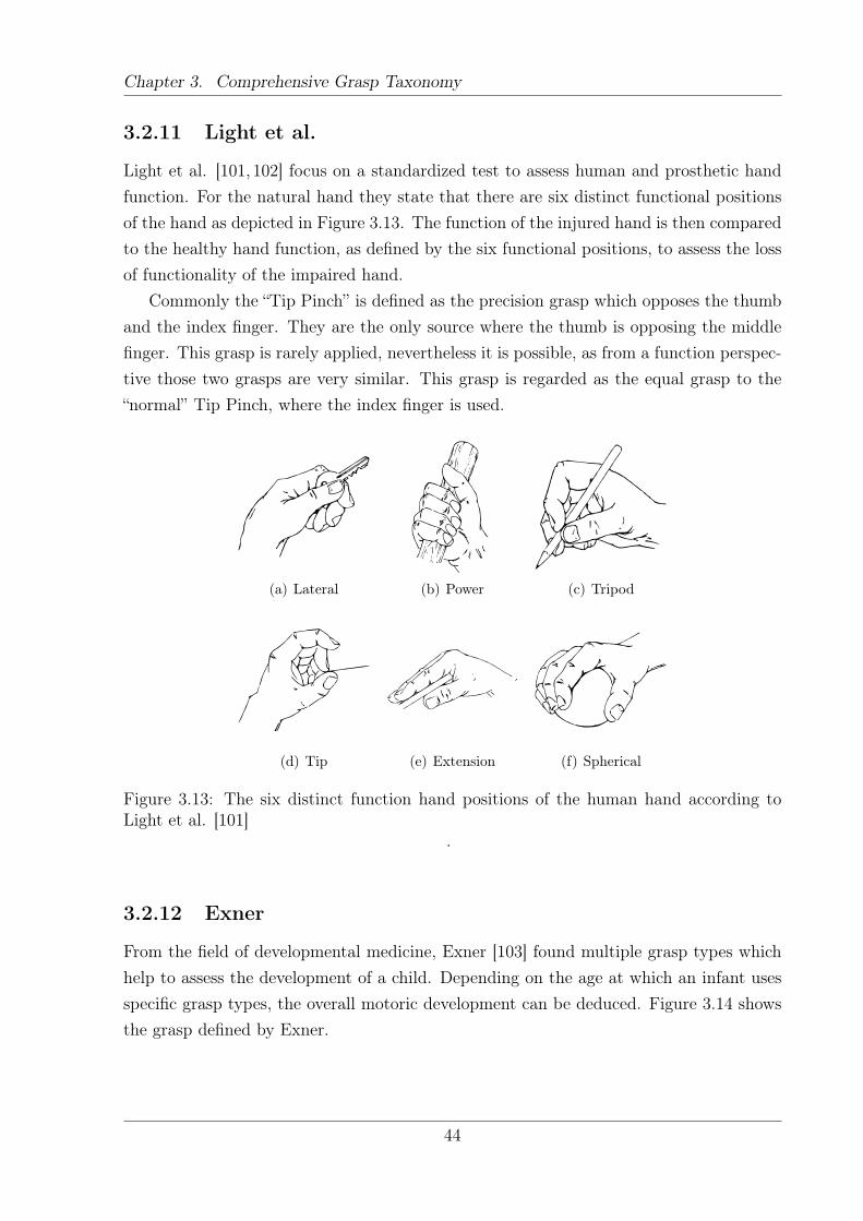
Chapter 3. Comprehensive Grasp Taxonomy
3.2.11 Light et al.
Light et al. [101, 102] focus on a standardized test to assess human and prosthetic handfunction. For the natural hand they state that there are six distinct functional positionsof the hand as depicted in Figure 3.13. The function of the injured hand is then comparedto the healthy hand function, as defined by the six functional positions, to assess the lossof functionality of the impaired hand.
Commonly the “Tip Pinch” is defined as the precision grasp which opposes the thumband the index finger. They are the only source where the thumb is opposing the middlefinger. This grasp is rarely applied, nevertheless it is possible, as from a function perspec-tive those two grasps are very similar. This grasp is regarded as the equal grasp to the“normal” Tip Pinch, where the index finger is used.
(a) Lateral (b) Power (c) Tripod
(d) Tip (e) Extension (f) Spherical
Figure 3.13: The six distinct function hand positions of the human hand according toLight et al. [101]
.
3.2.12 Exner
From the field of developmental medicine, Exner [103] found multiple grasp types whichhelp to assess the development of a child. Depending on the age at which an infant usesspecific grasp types, the overall motoric development can be deduced. Figure 3.14 showsthe grasp defined by Exner.
44
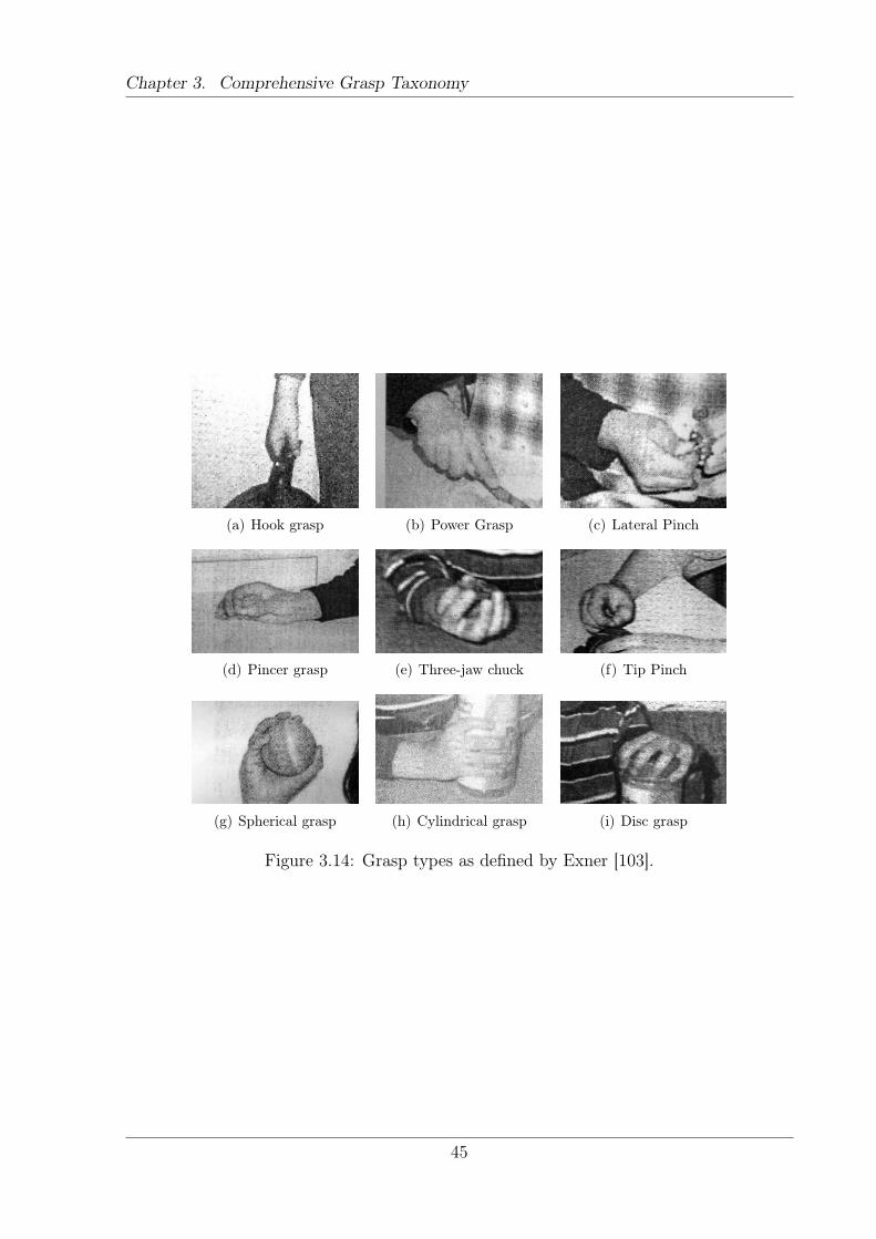
Chapter 3. Comprehensive Grasp Taxonomy
(a) Hook grasp (b) Power Grasp (c) Lateral Pinch
(d) Pincer grasp (e) Three-jaw chuck (f) Tip Pinch
(g) Spherical grasp (h) Cylindrical grasp (i) Disc grasp
Figure 3.14: Grasp types as defined by Exner [103].
45
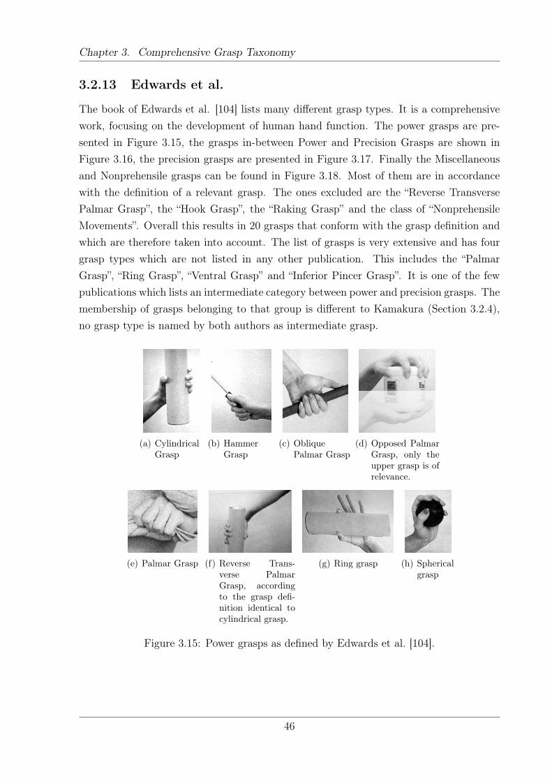
Chapter 3. Comprehensive Grasp Taxonomy
3.2.13 Edwards et al.
The book of Edwards et al. [104] lists many different grasp types. It is a comprehensivework, focusing on the development of human hand function. The power grasps are pre-sented in Figure 3.15, the grasps in-between Power and Precision Grasps are shown inFigure 3.16, the precision grasps are presented in Figure 3.17. Finally the Miscellaneousand Nonprehensile grasps can be found in Figure 3.18. Most of them are in accordancewith the definition of a relevant grasp. The ones excluded are the “Reverse TransversePalmar Grasp”, the “Hook Grasp”, the “Raking Grasp” and the class of “NonprehensileMovements”. Overall this results in 20 grasps that conform with the grasp definition andwhich are therefore taken into account. The list of grasps is very extensive and has fourgrasp types which are not listed in any other publication. This includes the “PalmarGrasp”, “Ring Grasp”, “Ventral Grasp” and “Inferior Pincer Grasp”. It is one of the fewpublications which lists an intermediate category between power and precision grasps. Themembership of grasps belonging to that group is different to Kamakura (Section 3.2.4),no grasp type is named by both authors as intermediate grasp.
(a) CylindricalGrasp
(b) HammerGrasp
(c) ObliquePalmar Grasp
(d) Opposed PalmarGrasp, only theupper grasp is ofrelevance.
(e) Palmar Grasp (f) Reverse Trans-verse PalmarGrasp, accordingto the grasp defi-nition identical tocylindrical grasp.
(g) Ring grasp (h) Sphericalgrasp
Figure 3.15: Power grasps as defined by Edwards et al. [104].
46
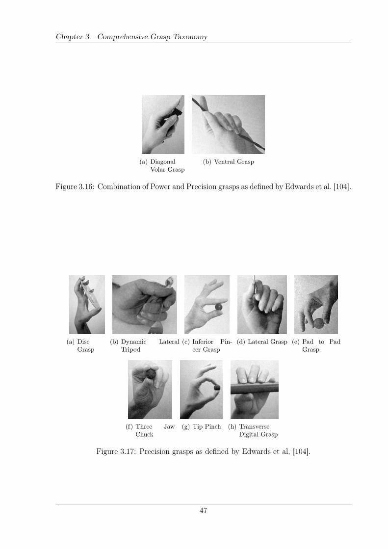
Chapter 3. Comprehensive Grasp Taxonomy
(a) DiagonalVolar Grasp
(b) Ventral Grasp
Figure 3.16: Combination of Power and Precision grasps as defined by Edwards et al. [104].
(a) DiscGrasp
(b) Dynamic LateralTripod
(c) Inferior Pin-cer Grasp
(d) Lateral Grasp (e) Pad to PadGrasp
(f) Three JawChuck
(g) Tip Pinch (h) TransverseDigital Grasp
Figure 3.17: Precision grasps as defined by Edwards et al. [104].
47
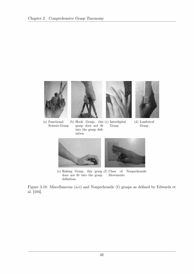
Chapter 3. Comprehensive Grasp Taxonomy
(a) FunctionalScissors Grasp
(b) Hook Grasp, thisgrasp does not fitinto the grasp defi-nition.
(c) InterdigitalGrasp
(d) LumbricalGrasp
(e) Raking Grasp, this graspdoes not fit into the graspdefinition.
(f) Class of NonprehensileMovements
Figure 3.18: Miscellaneous (a-e) and Nonprehensile (f) grasps as defined by Edwards etal. [104].
48
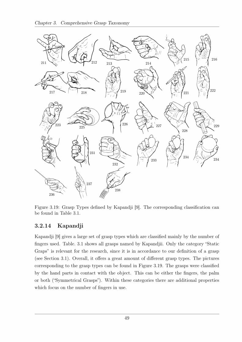
Chapter 3. Comprehensive Grasp Taxonomy
211 212 213 214215 216
217 218 219220 221
222
223225
226227
228
229
230231
232233
234
236
237
238
234
Figure 3.19: Grasp Types defined by Kapandji [9]. The corresponding classification canbe found in Table 3.1.
3.2.14 Kapandji
Kapandji [9] gives a large set of grasp types which are classified mainly by the number offingers used. Table. 3.1 shows all grasps named by Kapandjii. Only the category “StaticGraps” is relevant for the research, since it is in accordance to our definition of a grasp(see Section 3.1). Overall, it offers a great amount of different grasp types. The picturescorresponding to the grasp types can be found in Figure 3.19. The grasps were classifiedby the hand parts in contact with the object. This can be either the fingers, the palmor both (“Symmetrical Grasps”). Within these categories there are additional propertieswhich focus on the number of fingers in use.
49
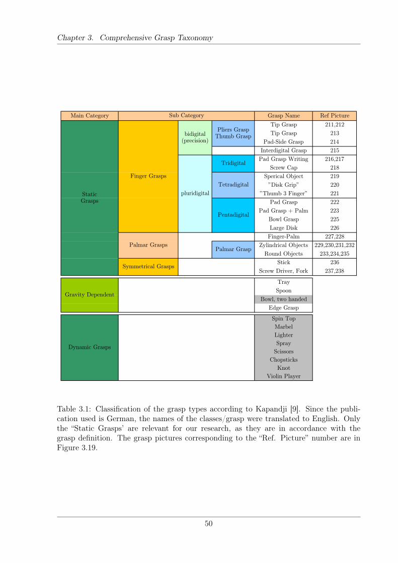
Chapter 3. Comprehensive Grasp Taxonomy
Main Category Grasp Name Ref Picture
Tip Grasp 211,212
Tip Grasp 213
Pad-Side Grasp 214
Interdigital Grasp 215
Pad Grasp Writing 216,217
Screw Cap 218
Sperical Object 219
"Disk Grip" 220
"Thumb 3 Finger" 221
Pad Grasp 222
Pad Grasp + Palm 223
Bowl Grasp 225
Large Disk 226
Finger-Palm 227,228
Zylindrical Objects 229,230,231,232
Round Objects 233,234,235
Stick 236
Screw Driver, Fork 237,238
Tray
Spoon
Bowl, two handed
Edge Grasp
Spin Top
Marbel
Lighter
Spray
Scissors
Chopsticks
Knot
Violin Player
Palmar Grasp
Symmetrical Grasps
Gravity Dependent
Dynamic Grasps
Sub Category
StaticGrasps
Finger Grasps
bidigital(precision)
Pliers GraspThumb Grasp
pluridigital
Tridigital
Tetradigital
Pentadigital
Palmar Grasps
Table 3.1: Classification of the grasp types according to Kapandji [9]. Since the publi-cation used is German, the names of the classes/grasp were translated to English. Onlythe “Static Grasps’ are relevant for our research, as they are in accordance with thegrasp definition. The grasp pictures corresponding to the “Ref. Picture” number are inFigure 3.19.
50
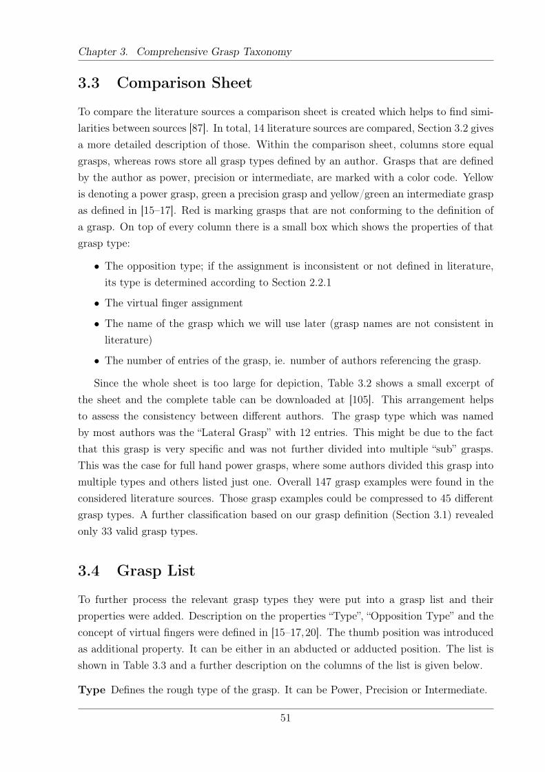
Chapter 3. Comprehensive Grasp Taxonomy
3.3 Comparison Sheet
To compare the literature sources a comparison sheet is created which helps to find simi-larities between sources [87]. In total, 14 literature sources are compared, Section 3.2 givesa more detailed description of those. Within the comparison sheet, columns store equalgrasps, whereas rows store all grasp types defined by an author. Grasps that are definedby the author as power, precision or intermediate, are marked with a color code. Yellowis denoting a power grasp, green a precision grasp and yellow/green an intermediate graspas defined in [15–17]. Red is marking grasps that are not conforming to the definition ofa grasp. On top of every column there is a small box which shows the properties of thatgrasp type:
• The opposition type; if the assignment is inconsistent or not defined in literature,its type is determined according to Section 2.2.1
• The virtual finger assignment
• The name of the grasp which we will use later (grasp names are not consistent inliterature)
• The number of entries of the grasp, ie. number of authors referencing the grasp.
Since the whole sheet is too large for depiction, Table 3.2 shows a small excerpt ofthe sheet and the complete table can be downloaded at [105]. This arrangement helpsto assess the consistency between different authors. The grasp type which was namedby most authors was the “Lateral Grasp” with 12 entries. This might be due to the factthat this grasp is very specific and was not further divided into multiple “sub” grasps.This was the case for full hand power grasps, where some authors divided this grasp intomultiple types and others listed just one. Overall 147 grasp examples were found in theconsidered literature sources. Those grasp examples could be compressed to 45 differentgrasp types. A further classification based on our grasp definition (Section 3.1) revealedonly 33 valid grasp types.
3.4 Grasp List
To further process the relevant grasp types they were put into a grasp list and theirproperties were added. Description on the properties “Type”, “Opposition Type” and theconcept of virtual fingers were defined in [15–17,20]. The thumb position was introducedas additional property. It can be either in an abducted or adducted position. The list isshown in Table 3.3 and a further description on the columns of the list is given below.
Type Defines the rough type of the grasp. It can be Power, Precision or Intermediate.
51
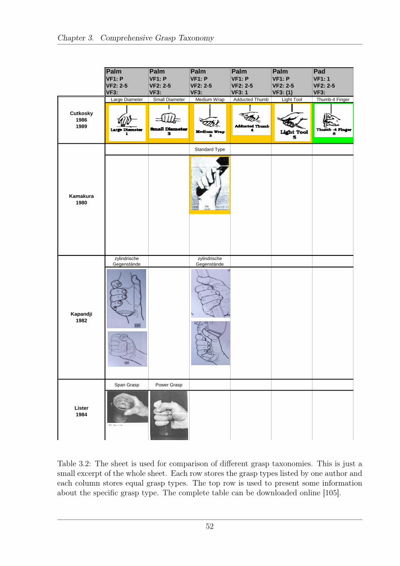
Chapter 3. Comprehensive Grasp Taxonomy
Palm Palm Palm Palm Palm PadVF1: P VF1: P VF1: P VF1: P VF1: P VF1: 1
VF2: 2-5 VF2: 2-5 VF2: 2-5 VF2: 2-5 VF2: 2-5 VF2: 2-5
VF3: VF3: VF3: VF3: 1 VF3: (1) VF3:
Large Diameter Small Diameter Medium Wrap Adducted Thumb Light Tool Thumb-4 Finger
Standard Type
zylindrische
Gegenstände
zylindrische
Gegenstände
Span Grasp Power Grasp
Kapandji
1982
Lister
1984
Cutkosky
1986
1989
Kamakura
1980
Table 3.2: The sheet is used for comparison of different grasp taxonomies. This is just asmall excerpt of the whole sheet. Each row stores the grasp types listed by one author andeach column stores equal grasp types. The top row is used to present some informationabout the specific grasp type. The complete table can be downloaded online [105].
52
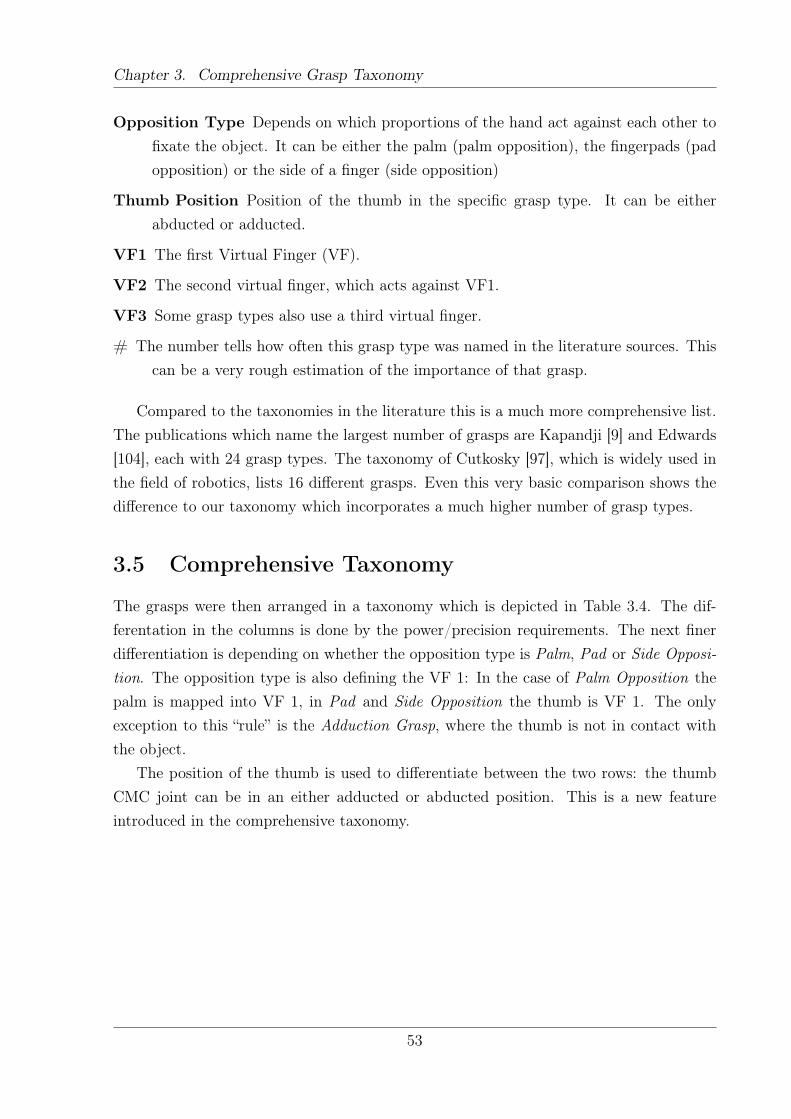
Chapter 3. Comprehensive Grasp Taxonomy
Opposition Type Depends on which proportions of the hand act against each other tofixate the object. It can be either the palm (palm opposition), the fingerpads (padopposition) or the side of a finger (side opposition)
Thumb Position Position of the thumb in the specific grasp type. It can be eitherabducted or adducted.
VF1 The first Virtual Finger (VF).
VF2 The second virtual finger, which acts against VF1.
VF3 Some grasp types also use a third virtual finger.
# The number tells how often this grasp type was named in the literature sources. Thiscan be a very rough estimation of the importance of that grasp.
Compared to the taxonomies in the literature this is a much more comprehensive list.The publications which name the largest number of grasps are Kapandji [9] and Edwards[104], each with 24 grasp types. The taxonomy of Cutkosky [97], which is widely used inthe field of robotics, lists 16 different grasps. Even this very basic comparison shows thedifference to our taxonomy which incorporates a much higher number of grasp types.
3.5 Comprehensive Taxonomy
The grasps were then arranged in a taxonomy which is depicted in Table 3.4. The dif-ferentation in the columns is done by the power/precision requirements. The next finerdifferentiation is depending on whether the opposition type is Palm, Pad or Side Opposi-tion. The opposition type is also defining the VF 1: In the case of Palm Opposition thepalm is mapped into VF 1, in Pad and Side Opposition the thumb is VF 1. The onlyexception to this “rule” is the Adduction Grasp, where the thumb is not in contact withthe object.
The position of the thumb is used to differentiate between the two rows: the thumbCMC joint can be in an either adducted or abducted position. This is a new featureintroduced in the comprehensive taxonomy.
53
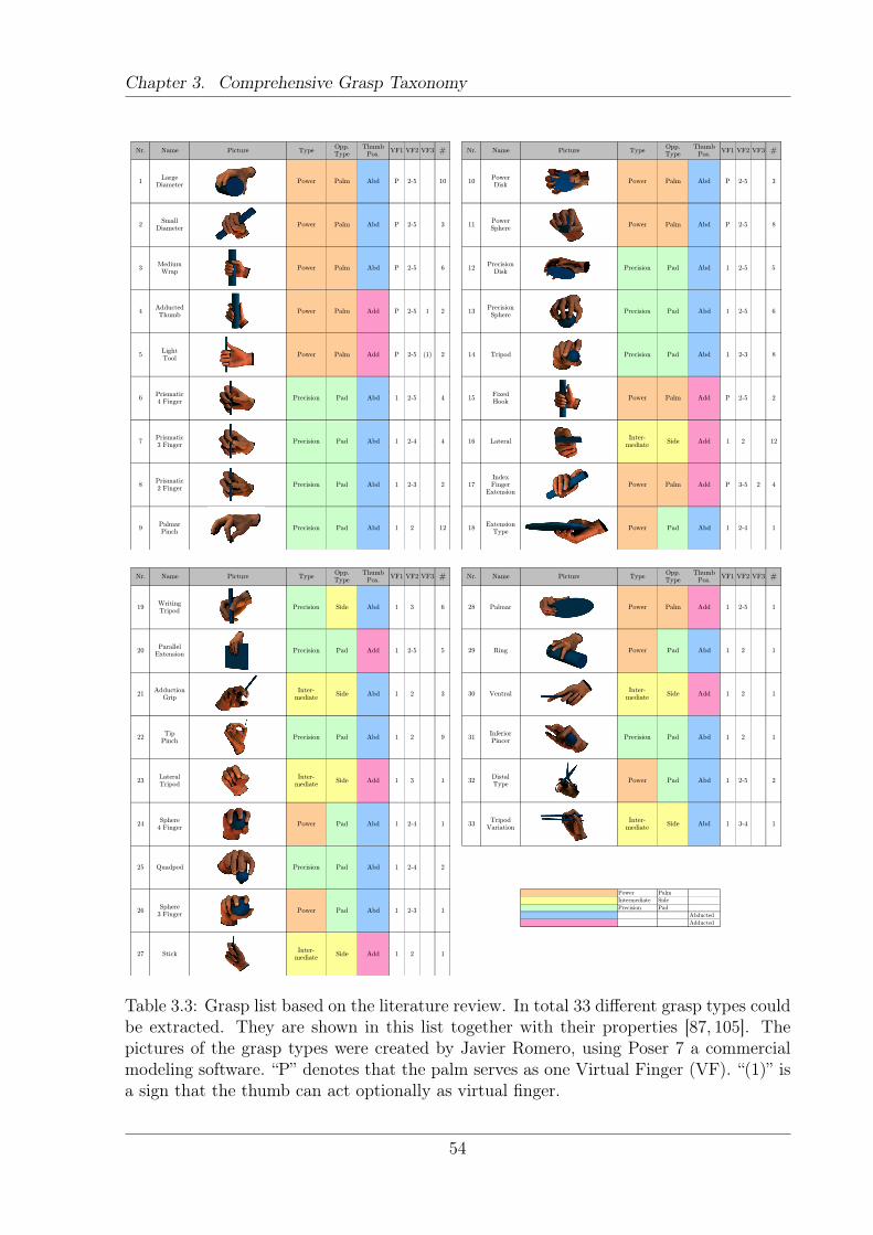
Chapter 3. Comprehensive Grasp Taxonomy
Nr. Name Picture TypeOpp.Type
ThumbPos.
VF1 VF2 VF3 #
1Large
DiameterPower Palm Abd P 2-5 10
2Small
DiameterPower Palm Abd P 2-5 3
3MediumWrap
Power Palm Abd P 2-5 6
4AdductedThumb
Power Palm Add P 2-5 1 2
5LightTool
Power Palm Add P 2-5 (1) 2
6Prismatic4 Finger
Precision Pad Abd 1 2-5 4
7Prismatic3 Finger
Precision Pad Abd 1 2-4 4
8Prismatic2 Finger
Precision Pad Abd 1 2-3 2
9PalmarPinch
Precision Pad Abd 1 2 12
Grasp List, 12.09.2011 GRASP / Otto Bock / Thomas Feix Page 1/4
Nr. Name Picture TypeOpp.Type
ThumbPos.
VF1 VF2 VF3 #
10PowerDisk
Power Palm Abd P 2-5 3
11PowerSphere
Power Palm Abd P 2-5 8
12Precision
DiskPrecision Pad Abd 1 2-5 5
13PrecisionSphere
Precision Pad Abd 1 2-5 6
14 Tripod Precision Pad Abd 1 2-3 8
15FixedHook
Power Palm Add P 2-5 2
16 LateralInter-
mediateSide Add 1 2 12
17IndexFinger
ExtensionPower Palm Add P 3-5 2 4
18Extension
TypePower Pad Abd 1 2-4 1
Grasp List, 12.09.2011 GRASP / Otto Bock / Thomas Feix Page 2/4
Nr. Name Picture TypeOpp.Type
ThumbPos.
VF1 VF2 VF3 #
19WritingTripod
Precision Side Abd 1 3 6
20Parallel
ExtensionPrecision Pad Add 1 2-5 5
21Adduction
GripInter-
mediateSide Abd 1 2 3
22Tip
PinchPrecision Pad Abd 1 2 9
23LateralTripod
Inter-mediate
Side Add 1 3 1
24Sphere
4 FingerPower Pad Abd 1 2-4 1
25 Quadpod Precision Pad Abd 1 2-4 2
26Sphere
3 FingerPower Pad Abd 1 2-3 1
27 StickInter-
mediateSide Add 1 2 1
Grasp List, 12.09.2011 GRASP / Otto Bock / Thomas Feix Page 3/4
Nr. Name Picture TypeOpp.Type
ThumbPos.
VF1 VF2 VF3 #
28 Palmar Power Palm Add 1 2-5 1
29 Ring Power Pad Abd 1 2 1
30 VentralInter-
mediateSide Add 1 2 1
31Inferior Pincer
Precision Pad Abd 1 2 1
32DistalType
Power Pad Abd 1 2-5 2
33Tripod
VariationInter-
mediateSide Abd 1 3-4 1
Power Palm
Intermediate Side
Precision Pad
Abducted
Adducted
Grasp List, 12.09.2011 GRASP / Otto Bock / Thomas Feix Page 4/4
Table 3.3: Grasp list based on the literature review. In total 33 different grasp types couldbe extracted. They are shown in this list together with their properties [87, 105]. Thepictures of the grasp types were created by Javier Romero, using Poser 7 a commercialmodeling software. “P” denotes that the palm serves as one Virtual Finger (VF). “(1)” isa sign that the thumb can act optionally as virtual finger.
54
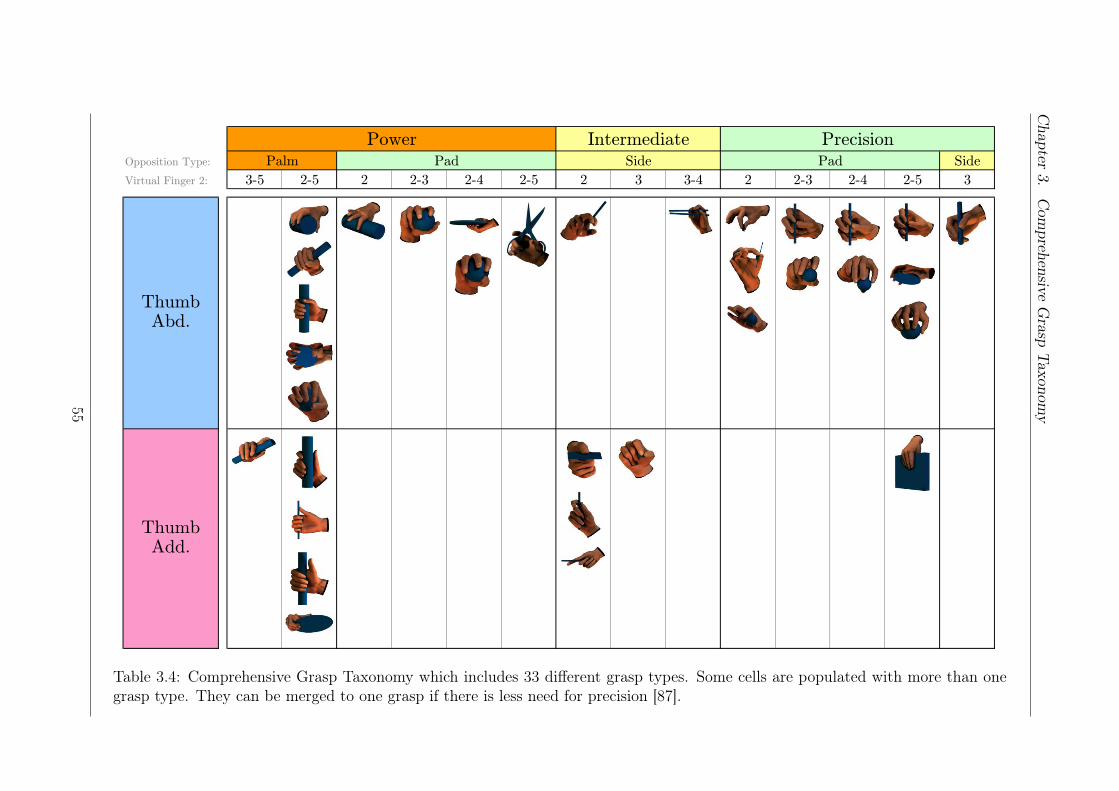
Chapter
3.Com
prehensiveGrasp
Taxonomy
Opposition Type: Side
Virtual Finger 2: 3-5 2-5 2 2-3 2-4 2-5 2 3 3-4 2 2-3 2-4 2-5 3
Side Pad
Thumb Abd.
Thumb Add.
Power Intermediate PrecisionPalm Pad
Grasp Taxonomy, 12.09.2011 GRASP / Otto Bock / Thomas FeixTable 3.4: Comprehensive Grasp Taxonomy which includes 33 different grasp types. Some cells are populated with more than onegrasp type. They can be merged to one grasp if there is less need for precision [87].
55
Chapter 3. Comprehensive Grasp Taxonomy
Merging of grasps within one cell
Many grasps have similar properties (opposition type, thumb position etc.), therefore somecells are populated with more than one grasp. The sole difference between such graspswithin one cell is the shape of the object. This offers the possibility to reduce the set ofall 33 grasps down to 17 grasps by merging the grasps within one cell to a corresponding“standard” grasp. Depending on the task, this offers the possibility to choose between twodifferent levels of accuracy of the grasp classification.
As a comparison, the classification of Cutkosky [97] has 15 different grasp types that fitinto our definition of a grasp. This is close to the amount of grasps the reduced taxonomyhas. However, our comparison shows that even though the number of grasps is nearlythe same, the classification is very different. When the grasps from [97] are classifiedaccording to the presented scheme, the grasps only populate 7 cells. That is a reductionby more than half. As [97] mainly differ grasps by the object properties this reduction isonly natural. The differentiation between object properties is done within one cell.
On the other hand, Kamakura [20] has no multiple entries in one cell. That is espe-cially reassuring because humans were observed grasping 98 different objects with staticgrasps. That is very close to natural human hand usage and therefore it is reassuringthat the comprehensive taxonomy has a similar result. The study was performed in re-stricted conditions, consequently there is no information about the occurrence of graspsin unconstrained conditions. The grasp types used by humans should be the same in con-strained and unconstraint conditions, as it can be assumed that humans always use thesame grasping patterns. The occurrence frequency might shift in laboratory conditions,since the subjects are exposed to situations which might be very unlikely in real life.
Analysis of Power and Precision Grasps
Of the 14 authors represented in the survey only four classified their grasps as power,precision and/or intermediate grasps. They showed a large consensus about the allocationof the categories. In total 16 grasps can be compared based on that assignment. Of them,13 grasps showed total consensus, which is an conformity of 81%. Interestingly, the lateralgrasp was classified either as precision grasp [97, 100]; intermediate [20]; or power grasp[104]. So it seems that this grasp takes an intermediate stage between power and precision,what Iberall [17] also acknowledges. This “in between” state of the grasp is representedwithin our taxonomy since it is put into the intermediate category.
Some inconsistency was found in the tripod grasps (“real” tripod and writing tripod),since Kamakura [20] classified them as intermediate grasps, apart from that it was clas-sified as precision. Because of the dominant need for delicate handling, these grips wereput into the precision category.
56
Chapter 3. Comprehensive Grasp Taxonomy
3.6 Discussion
The goal was to generate a comprehensive human grasp taxonomy for further analysis ofhuman grasping movements. Since the area of human hand usage is very wide, the authordefined which grasps are relevant. This definition excludes some grasps, but most of thegrasps named in the literature are in accordance with this definition. Overall 147 graspexamples were found in literature and based on those 33 different grasp types could beextracted. The grasp types were then arranged in a self created taxonomy. The taxonomyis called comprehensive because it incorporates all major preceding publications. In thatrespect it is much more complete than any other presented taxonomy. Yet it suffers fromthe limitations it inherits from the publications it is based on.
The grasp types are arranged purely on the authors’ intuition and are not based on realmeasurements. There is no guarantee that the listed grasps correspond to the ones usedby humans. To the best knowledge of the author, there is no extensive study availablewhich tries to classify human hand postures based on a measurement of real life handusage. As the largest subset of grasp types was searched for, the presented taxonomycovers more hand postures than the grasp taxonomies presented in literature. If this issufficient, or if there are major hand configurations missing cannot be determined. Ifsuch information would be available, it could be used to reduce the numbers of graspsand direct the effort onto the most important grasps. That would simplify the work inthe following Sections as no effort is spend on grasps that are of no importance in reallife.
Only very recently a preliminary study on the occurrence of different grasp types waspublished [98]. The finding is that a few grasp types constitute the vast amount of graspsneeded. The study is limited to two subjects in unique environments. As the result is ofa preliminary nature only and was published very recently, it is not taken into account inthe following.
The only two grasp types that are disregarded, because the assumption is that theyare very rarely used, are the “Distal Type” (grasp number 32 in Table 3.3) and the “TripodVariation” (grasp number 33 in Table 3.3). Both grasps are very special, since they areused on a specific object and also in a specific task. That reduces the generality of sucha grasp and therefore most likely their occurrence frequency. The “Distal Type”, which isthe grasp for chopsticks, was only introduced by Kamakura et al. [20].
The grasp types that were found will serve as a solid basis for further research. 31grasp types will be considered in the measurement on human hand kinematics which isdescribed in the next Chapter.
57
Chapter 4Quantification of Anthropomorphic HandPerformance
The goal of this Chapter is to create a method to determine the level of anthropomorphismof prosthetic and robotic hands. Once the measure is defined, it is used to assess the scoreof two existing prosthetic and one robotic hand. This Chapter is based to a large part on[106], where the idea of quantification of anthropomorphic hand performance is presented.At the end of this Chapter, the system, based on a nonlinear dimensionality reductionalgorithm, will be contrasted against PCA. The comparison shows astonishing results onthe behavior of those two methods.
The remainder of this Chapter is structured as follows. Section 4.1 presents the gen-eral idea how the level of anthropomorphism of a given kinematic hand setup can bedetermined. A measure on how that can be done in a quantitative manner is presented inSection 4.2. To make the system work, a low dimensional space with very specific prop-erties is needed. Section 4.3 is dedicated to finding such a space. Finally, in Section 4.4existing hand designs will be evaluated.
4.1 System Description
Figure 4.1 and 4.2 visualize the basic idea [106]: the term action manifold is used to referto the postures a hand can reach. This action manifold can represent all postures a handcan reach or a subset of those, generated for a specific purpose. For example, one maygenerate an action manifold that represents different types of tri-fingered grasps generatedby a hand.
The dimensionality of the space in which this action manifold resides depends on howthe hand postures are represented. If fingertip poses are measured (position + orienta-tion) and represented with translational and rotational parameters (e.g. Euler angles),
58
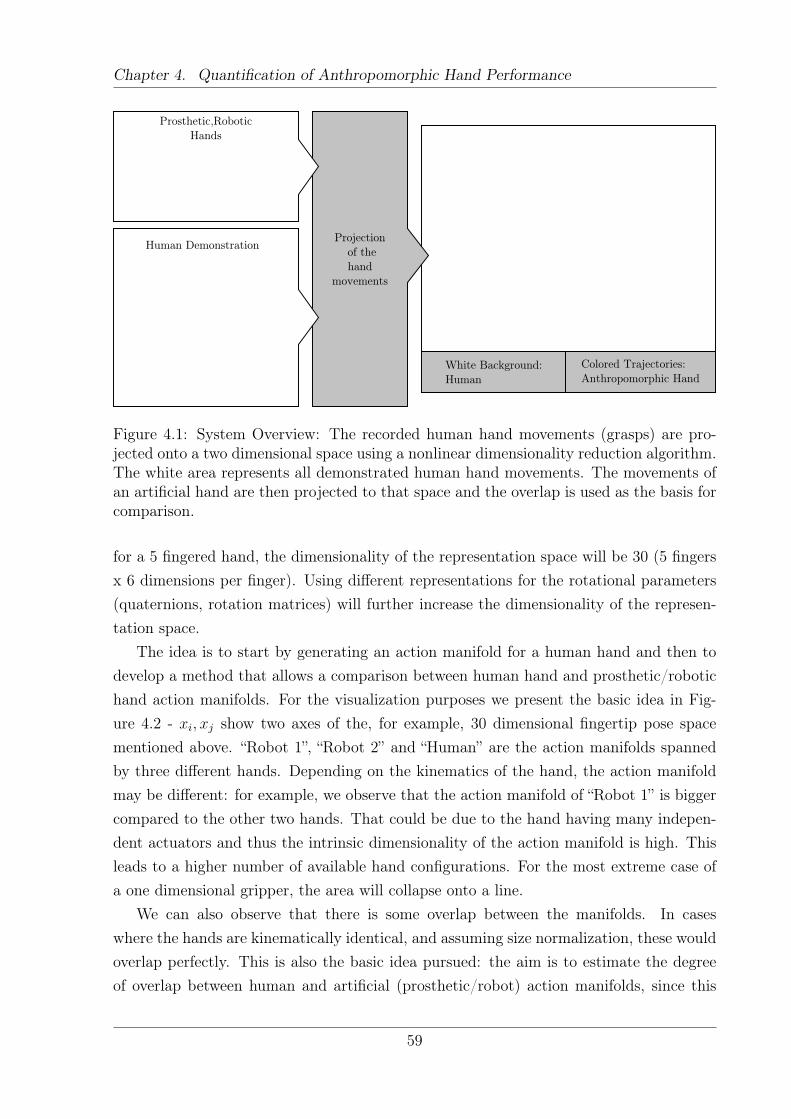
Chapter 4. Quantification of Anthropomorphic Hand Performance
Colored Trajectories:
Anthropomorphic Hand
White Background:
Human
Projection
of the
hand
movements
Human Demonstration
Figure 4.1: System Overview: The recorded human hand movements (grasps) are pro-jected onto a two dimensional space using a nonlinear dimensionality reduction algorithm.The white area represents all demonstrated human hand movements. The movements ofan artificial hand are then projected to that space and the overlap is used as the basis forcomparison.
for a 5 fingered hand, the dimensionality of the representation space will be 30 (5 fingersx 6 dimensions per finger). Using different representations for the rotational parameters(quaternions, rotation matrices) will further increase the dimensionality of the represen-tation space.
The idea is to start by generating an action manifold for a human hand and then todevelop a method that allows a comparison between human hand and prosthetic/robotichand action manifolds. For the visualization purposes we present the basic idea in Fig-ure 4.2 - xi, xj show two axes of the, for example, 30 dimensional fingertip pose spacementioned above. “Robot 1”, “Robot 2” and “Human” are the action manifolds spannedby three different hands. Depending on the kinematics of the hand, the action manifoldmay be different: for example, we observe that the action manifold of “Robot 1” is biggercompared to the other two hands. That could be due to the hand having many indepen-dent actuators and thus the intrinsic dimensionality of the action manifold is high. Thisleads to a higher number of available hand configurations. For the most extreme case ofa one dimensional gripper, the area will collapse onto a line.
We can also observe that there is some overlap between the manifolds. In caseswhere the hands are kinematically identical, and assuming size normalization, these wouldoverlap perfectly. This is also the basic idea pursued: the aim is to estimate the degreeof overlap between human and artificial (prosthetic/robot) action manifolds, since this
59
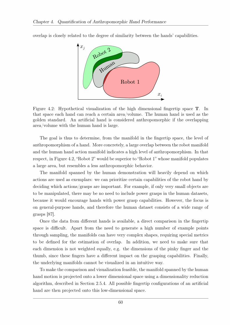
Chapter 4. Quantification of Anthropomorphic Hand Performance
overlap is closely related to the degree of similarity between the hands’ capabilities.
Human
Robot 1
Robot
2
xi
xj
Figure 4.2: Hypothetical visualization of the high dimensional fingertip space T. Inthat space each hand can reach a certain area/volume. The human hand is used as thegolden standard. An artificial hand is considered anthropomorphic if the overlappingarea/volume with the human hand is large.
The goal is thus to determine, from the manifold in the fingertip space, the level ofanthropomorphism of a hand. More concretely, a large overlap between the robot manifoldand the human hand action manifold indicates a high level of anthropomorphism. In thatrespect, in Figure 4.2, “Robot 2” would be superior to “Robot 1” whose manifold populatesa large area, but resembles a less anthropomorphic behavior.
The manifold spanned by the human demonstration will heavily depend on whichactions are used as exemplars: we can prioritize certain capabilities of the robot hand bydeciding which actions/grasps are important. For example, if only very small objects areto be manipulated, there may be no need to include power grasps in the human datasets,because it would encourage hands with power grasp capabilities. However, the focus ison general-purpose hands, and therefore the human dataset consists of a wide range ofgrasps [87].
Once the data from different hands is available, a direct comparison in the fingertipspace is difficult. Apart from the need to generate a high number of example pointsthrough sampling, the manifolds can have very complex shapes, requiring special metricsto be defined for the estimation of overlap. In addition, we need to make sure thateach dimension is not weighted equally, e.g. the dimensions of the pinky finger and thethumb, since these fingers have a different impact on the grasping capabilities. Finally,the underlying manifolds cannot be visualized in an intuitive way.
To make the comparison and visualization feasible, the manifold spanned by the humanhand motion is projected onto a lower dimensional space using a dimensionality reductionalgorithm, described in Section 2.5.4. All possible fingertip configurations of an artificialhand are then projected onto this low-dimensional space.
60
Chapter 4. Quantification of Anthropomorphic Hand Performance
Subsequently, the overlap is compared: a large overlap indicates that the hand is moresimilar to the human hand and thus more anthropomorphic.
As mentioned, one example of this mapping is shown in Figure 4.1 at the bottom. Thewhite background represents all human hand movements projected to two dimensions andthe colored trajectories are the projected movements of a prosthetic hand. The systemconsists of the following steps:
1) Human data generation: The first step is to generate a dataset of human graspingmovements. These movements define the benchmark manifold to which the manifoldof artificial hand movements will be compared to. Details on how this data wasobtained is presented in Section 4.3.
2) Dimensionality reduction: A nonlinear dimensionality reduction method is used toproject the high-dimensional manifold to a lower dimensional space suitable for vi-sualization and comparison. More details on the algorithm are given in Section 2.5.4and the properties of the latent space are described in Section 4.3.5.
3) Artificial hand dataset: Similar to the human dataset, a dataset of the movementsof the artificial hand is generated based on the forward kinematics.
4) Projection: The artificial hand dataset is projected to the low dimensional spacespanned by the human data. The projection of artificial hands is done in Section 4.4.
5) Overlap calculation: The overlap between the manifolds is measured in the lower-dimensional space. In order to quantify the overlap, an overlap measure is created,which is explained in Section 4.2.
The methodology differs from the approaches mentioned in Section 2.3.4 as it usesthe end effector (fingertip) space instead of the joint space representation. In the formerspace, the position and orientation (pose) of the fingertips encode the configuration ofthe hand. The advantage of using the fingertip space over joint space is that this spaceis not embodiment specific as all five fingered hands share the same fingertip space. Thismore general parametrization also incorporates information on the underlying kinematicsetup as, due to kinematic limitations, a hand cannot populate the complete space. Thismeans that by specifying the points reachable in fingertip space (the action manifold) wealso provide a notion of the kinematic structure of the hand.
4.2 Overlap Measure
Once the movements of an artificial hand are projected onto the human spanned latentspace, the overlap between that space and the human spanned manifold has to be mea-sured. Our approach is to discretize the latent space into a regular grid and count how
61
Chapter 4. Quantification of Anthropomorphic Hand Performance
many cells are populated by a given hand design. For example, for a one DoF gripperthe projection becomes a single line, whereas for a more complex hand with multipleactuators this can be a concentration of points with an arbitrary shape.
An important parameter for the calculation is the width of the cells as we regard allpoints within one cell as being equal. With equal we mean that if we vary the positionwithin that margin, the resulting hand posture will only change by a small degree. Aspresented in Section 4.3.2, each subject performed the grasp types twice. The differencein the final grasp posture of the hand of trial one and trial two can be regarded as beingirrelevant as both configurations resulted in a stable grasp. Points belonging to the actualgrasping poses of trial one and two are projected onto the latent space and the distancebetween two corresponding points is averaged over all trials and subjects. This results ina maximum distance dx and dy in x and y direction respectively which can be regardedas being the same grasp. Those lengths will define the resolution of the grid in latentspace. In our case we divided the latent space (described in more detail in Section 4.3.7)into 48 rectangles along dimension one and into 45 rectangles along dimension two. Wedid not include more rectangles, as in the regions not shown in the Figure the confidencewas already very low (as indicated by the dark background in Figure 4.1).
The GP-LVM method models the mapping from the latent to high dimensional spaceusing a Gaussian Process. This mapping provides us with a mean (prediction of thehigh dimensional location of the point) and a variance. The inverse of the variance, orconfidence, is related to how certain the model is when reconstructing that point. Theconfidence is scaled into the interval [0, 1], where the white area in the latent space plotscorresponds to maximal confidence. A measure of the area of the human spanned latentspace Oh can be calculated by summing the area of each cell Ab = dx · dy weighted bytheir corresponding confidence Ci.
Oh =
Nb∑i=1
Ab · Ci (4.1)
Nb = 48 · 45 = 2160 is the total number of rectangles needed to cover the area of thelatent space where the confidence is nonzero.
The projection of the artificial hand movements discretized into V steps will result ina set of points H ∈ RV×2 whose overlap Or will be calculated. This is done by summingover all cells which are populated by at least one point Hv.
Or =
Nb∑i=1
Ab ·
Ci ∃Hv ∈ bi0 otherwise
(4.2)
Finally Or can be set into a relation to the area of human spanned space Oh and the
62
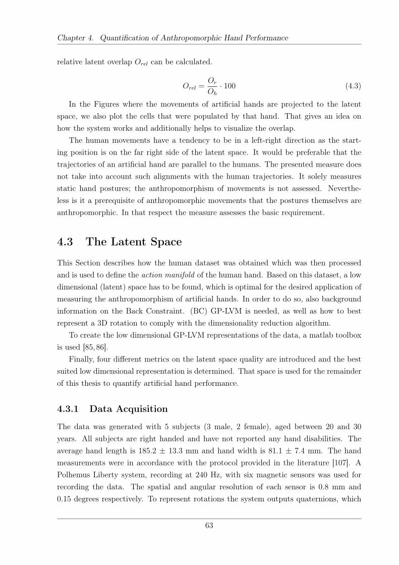
Chapter 4. Quantification of Anthropomorphic Hand Performance
relative latent overlap Orel can be calculated.
Orel =Or
Oh
· 100 (4.3)
In the Figures where the movements of artificial hands are projected to the latentspace, we also plot the cells that were populated by that hand. That gives an idea onhow the system works and additionally helps to visualize the overlap.
The human movements have a tendency to be in a left-right direction as the start-ing position is on the far right side of the latent space. It would be preferable that thetrajectories of an artificial hand are parallel to the humans. The presented measure doesnot take into account such alignments with the human trajectories. It solely measuresstatic hand postures; the anthropomorphism of movements is not assessed. Neverthe-less is it a prerequisite of anthropomorphic movements that the postures themselves areanthropomorphic. In that respect the measure assesses the basic requirement.
4.3 The Latent Space
This Section describes how the human dataset was obtained which was then processedand is used to define the action manifold of the human hand. Based on this dataset, a lowdimensional (latent) space has to be found, which is optimal for the desired application ofmeasuring the anthropomorphism of artificial hands. In order to do so, also backgroundinformation on the Back Constraint. (BC) GP-LVM is needed, as well as how to bestrepresent a 3D rotation to comply with the dimensionality reduction algorithm.
To create the low dimensional GP-LVM representations of the data, a matlab toolboxis used [85,86].
Finally, four different metrics on the latent space quality are introduced and the bestsuited low dimensional representation is determined. That space is used for the remainderof this thesis to quantify artificial hand performance.
4.3.1 Data Acquisition
The data was generated with 5 subjects (3 male, 2 female), aged between 20 and 30years. All subjects are right handed and have not reported any hand disabilities. Theaverage hand length is 185.2 ± 13.3 mm and hand width is 81.1 ± 7.4 mm. The handmeasurements were in accordance with the protocol provided in the literature [107]. APolhemus Liberty system, recording at 240 Hz, with six magnetic sensors was used forrecording the data. The spatial and angular resolution of each sensor is 0.8 mm and0.15 degrees respectively. To represent rotations the system outputs quaternions, which
63
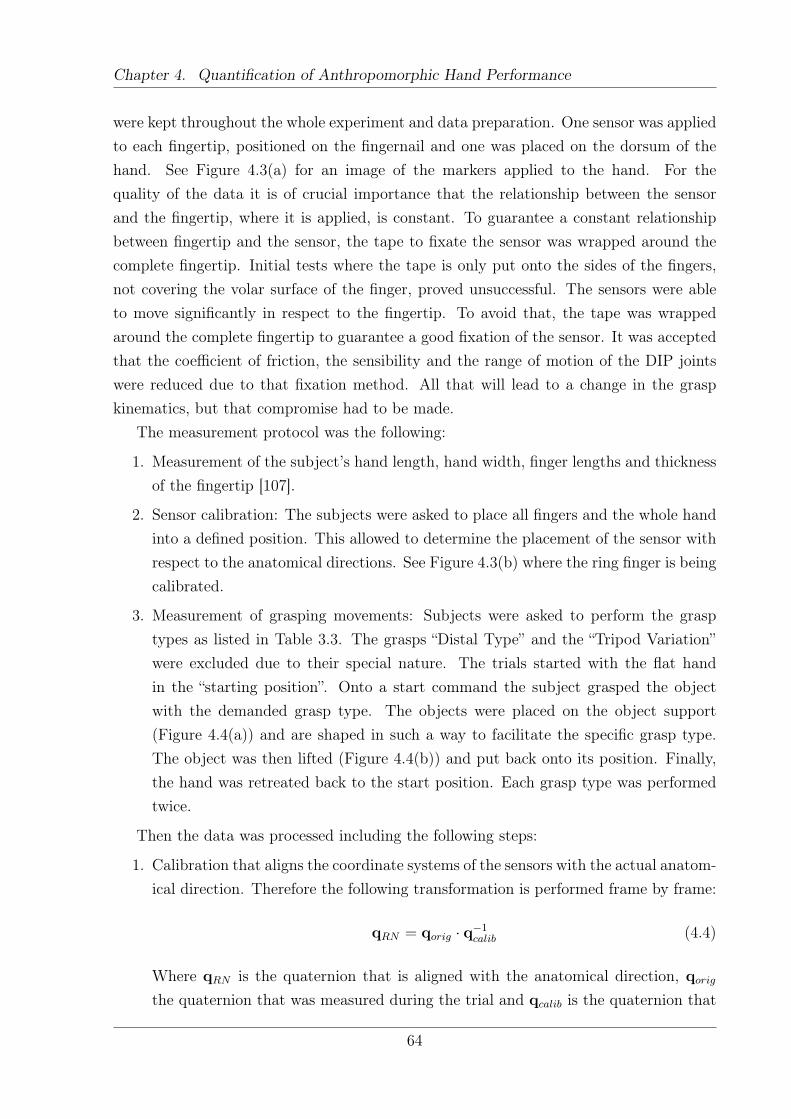
Chapter 4. Quantification of Anthropomorphic Hand Performance
were kept throughout the whole experiment and data preparation. One sensor was appliedto each fingertip, positioned on the fingernail and one was placed on the dorsum of thehand. See Figure 4.3(a) for an image of the markers applied to the hand. For thequality of the data it is of crucial importance that the relationship between the sensorand the fingertip, where it is applied, is constant. To guarantee a constant relationshipbetween fingertip and the sensor, the tape to fixate the sensor was wrapped around thecomplete fingertip. Initial tests where the tape is only put onto the sides of the fingers,not covering the volar surface of the finger, proved unsuccessful. The sensors were ableto move significantly in respect to the fingertip. To avoid that, the tape was wrappedaround the complete fingertip to guarantee a good fixation of the sensor. It was acceptedthat the coefficient of friction, the sensibility and the range of motion of the DIP jointswere reduced due to that fixation method. All that will lead to a change in the graspkinematics, but that compromise had to be made.
The measurement protocol was the following:
1. Measurement of the subject’s hand length, hand width, finger lengths and thicknessof the fingertip [107].
2. Sensor calibration: The subjects were asked to place all fingers and the whole handinto a defined position. This allowed to determine the placement of the sensor withrespect to the anatomical directions. See Figure 4.3(b) where the ring finger is beingcalibrated.
3. Measurement of grasping movements: Subjects were asked to perform the grasptypes as listed in Table 3.3. The grasps “Distal Type” and the “Tripod Variation”were excluded due to their special nature. The trials started with the flat handin the “starting position”. Onto a start command the subject grasped the objectwith the demanded grasp type. The objects were placed on the object support(Figure 4.4(a)) and are shaped in such a way to facilitate the specific grasp type.The object was then lifted (Figure 4.4(b)) and put back onto its position. Finally,the hand was retreated back to the start position. Each grasp type was performedtwice.
Then the data was processed including the following steps:
1. Calibration that aligns the coordinate systems of the sensors with the actual anatom-ical direction. Therefore the following transformation is performed frame by frame:
qRN = qorig · q−1calib (4.4)
Where qRN is the quaternion that is aligned with the anatomical direction, qorig
the quaternion that was measured during the trial and qcalib is the quaternion that
64
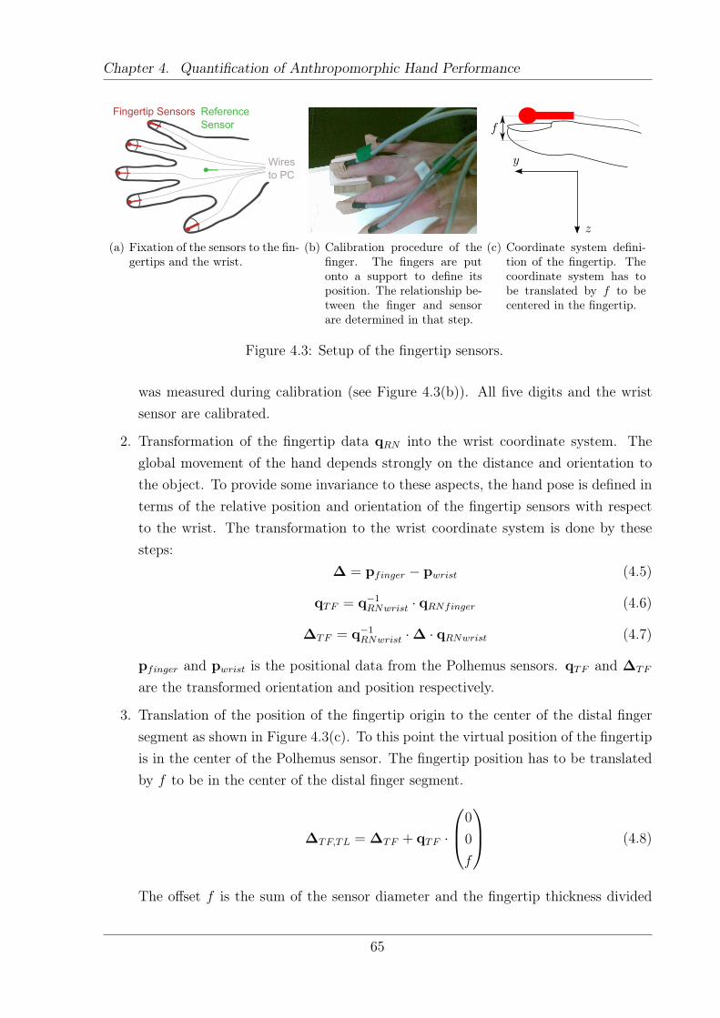
Chapter 4. Quantification of Anthropomorphic Hand Performance
Fingertip Sensors ReferenceSensor
Wiresto PC
(a) Fixation of the sensors to the fin-gertips and the wrist.
(b) Calibration procedure of thefinger. The fingers are putonto a support to define itsposition. The relationship be-tween the finger and sensorare determined in that step.
z
y
f
(c) Coordinate system defini-tion of the fingertip. Thecoordinate system has tobe translated by f to becentered in the fingertip.
Figure 4.3: Setup of the fingertip sensors.
was measured during calibration (see Figure 4.3(b)). All five digits and the wristsensor are calibrated.
2. Transformation of the fingertip data qRN into the wrist coordinate system. Theglobal movement of the hand depends strongly on the distance and orientation tothe object. To provide some invariance to these aspects, the hand pose is defined interms of the relative position and orientation of the fingertip sensors with respectto the wrist. The transformation to the wrist coordinate system is done by thesesteps:
∆ = pfinger − pwrist (4.5)
qTF = q−1RNwrist · qRNfinger (4.6)
∆TF = q−1RNwrist ·∆ · qRNwrist (4.7)
pfinger and pwrist is the positional data from the Polhemus sensors. qTF and ∆TF
are the transformed orientation and position respectively.
3. Translation of the position of the fingertip origin to the center of the distal fingersegment as shown in Figure 4.3(c). To this point the virtual position of the fingertipis in the center of the Polhemus sensor. The fingertip position has to be translatedby f to be in the center of the distal finger segment.
∆TF,TL = ∆TF + qTF ·
0
0
f
(4.8)
The offset f is the sum of the sensor diameter and the fingertip thickness divided
65
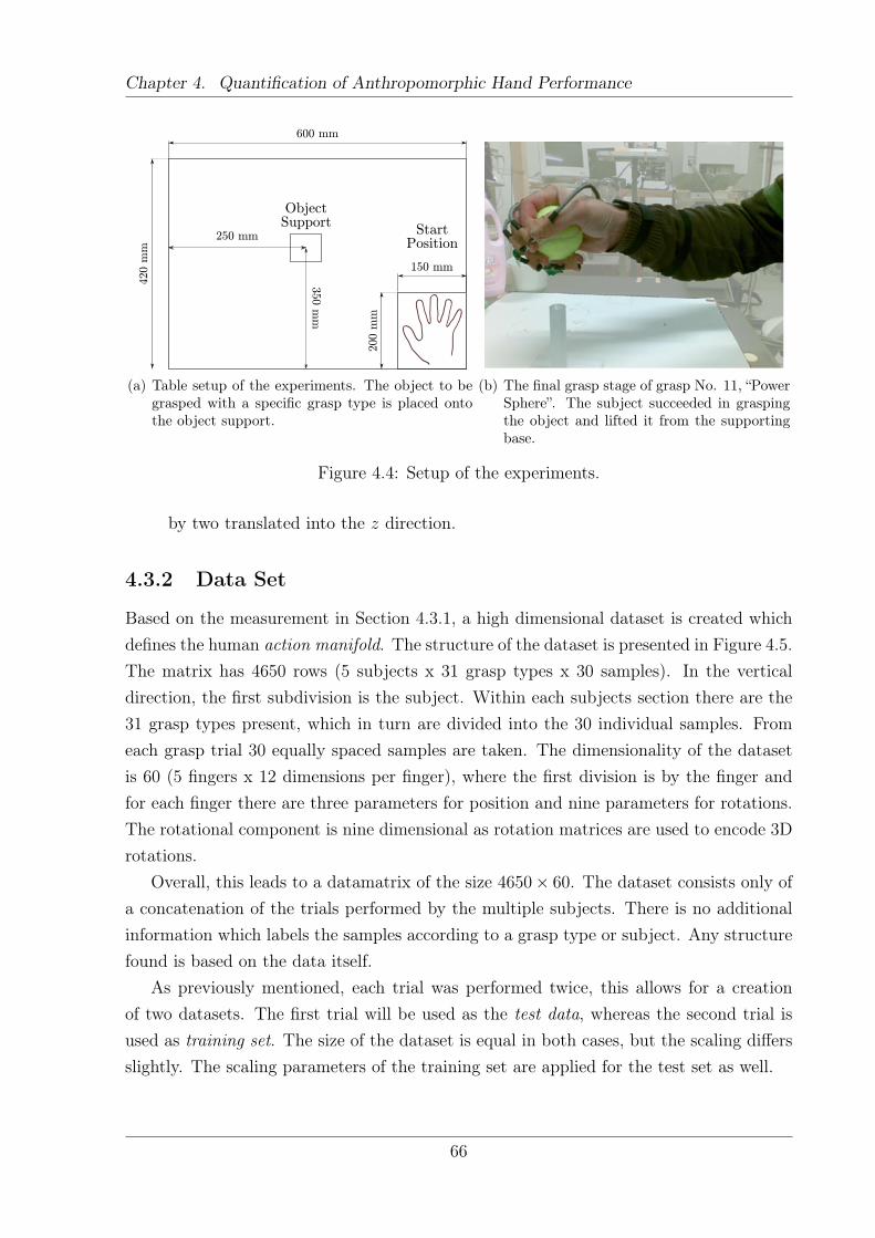
Chapter 4. Quantification of Anthropomorphic Hand Performance
StartPosition
ObjectSupport
600 mm420 m
m
250 mm
150 mm
200 m
m
350 m
m
(a) Table setup of the experiments. The object to begrasped with a specific grasp type is placed ontothe object support.
(b) The final grasp stage of grasp No. 11, “PowerSphere”. The subject succeeded in graspingthe object and lifted it from the supportingbase.
Figure 4.4: Setup of the experiments.
by two translated into the z direction.
4.3.2 Data Set
Based on the measurement in Section 4.3.1, a high dimensional dataset is created whichdefines the human action manifold. The structure of the dataset is presented in Figure 4.5.The matrix has 4650 rows (5 subjects x 31 grasp types x 30 samples). In the verticaldirection, the first subdivision is the subject. Within each subjects section there are the31 grasp types present, which in turn are divided into the 30 individual samples. Fromeach grasp trial 30 equally spaced samples are taken. The dimensionality of the datasetis 60 (5 fingers x 12 dimensions per finger), where the first division is by the finger andfor each finger there are three parameters for position and nine parameters for rotations.The rotational component is nine dimensional as rotation matrices are used to encode 3Drotations.
Overall, this leads to a datamatrix of the size 4650× 60. The dataset consists only ofa concatenation of the trials performed by the multiple subjects. There is no additionalinformation which labels the samples according to a grasp type or subject. Any structurefound is based on the data itself.
As previously mentioned, each trial was performed twice, this allows for a creationof two datasets. The first trial will be used as the test data, whereas the second trial isused as training set. The size of the dataset is equal in both cases, but the scaling differsslightly. The scaling parameters of the training set are applied for the test set as well.
66
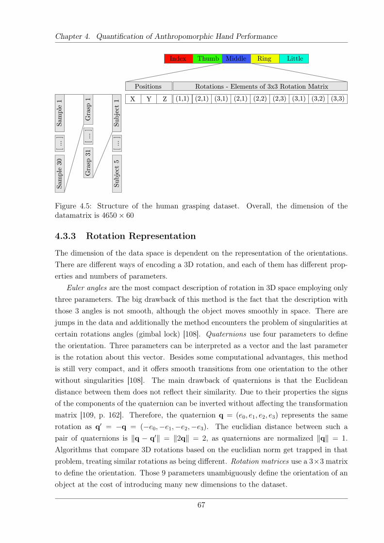
Chapter 4. Quantification of Anthropomorphic Hand Performance
Index Thumb Middle Ring Little
X Y Z
Positions Rotations - Elements of 3x3 Rotation MatrixG
rasp
1G
rasp
31
[ ... ]
Sam
ple
1Sam
ple
30
[ ... ]
Subje
ct 1
Subje
ct 5
[ ... ]
(1,1) (2,1) (3,1) (2,1) (2,2) (2,3) (3,1) (3,2) (3,3)
Figure 4.5: Structure of the human grasping dataset. Overall, the dimension of thedatamatrix is 4650× 60
4.3.3 Rotation Representation
The dimension of the data space is dependent on the representation of the orientations.There are different ways of encoding a 3D rotation, and each of them has different prop-erties and numbers of parameters.
Euler angles are the most compact description of rotation in 3D space employing onlythree parameters. The big drawback of this method is the fact that the description withthose 3 angles is not smooth, although the object moves smoothly in space. There arejumps in the data and additionally the method encounters the problem of singularities atcertain rotations angles (gimbal lock) [108]. Quaternions use four parameters to definethe orientation. Three parameters can be interpreted as a vector and the last parameteris the rotation about this vector. Besides some computational advantages, this methodis still very compact, and it offers smooth transitions from one orientation to the otherwithout singularities [108]. The main drawback of quaternions is that the Euclideandistance between them does not reflect their similarity. Due to their properties the signsof the components of the quaternion can be inverted without affecting the transformationmatrix [109, p. 162]. Therefore, the quaternion q = (e0, e1, e2, e3) represents the samerotation as q′ = −q = (−e0,−e1,−e2,−e3). The euclidian distance between such apair of quaternions is ‖q − q′‖ = ‖2q‖ = 2, as quaternions are normalized ‖q‖ = 1.Algorithms that compare 3D rotations based on the euclidian norm get trapped in thatproblem, treating similar rotations as being different. Rotation matrices use a 3×3 matrixto define the orientation. Those 9 parameters unambiguously define the orientation of anobject at the cost of introducing many new dimensions to the dataset.
67
Chapter 4. Quantification of Anthropomorphic Hand Performance
For the given application, the rotation matrix representation is the most suitable, asit unambiguously defines the 3D orientation of an object. We will disregard the other rep-resentations, even if their description would be more compact. The additional dimensionsintroduced by the rotation representation will not pose a large problem to the DR as thedimensions are perfectly coupled and can be therefore reduced without loss of information.
Scaling Methods
Each dimension of the human dataset has a different range. The reason for this being thatsome represent rotations, whereas others store positions. Additionally, different positionaldimensions have a different movement spectrum. As the error function is spherical, eachdimension is treated equally - thus dimensions with a large variance are assigned a higherrelative importance. By scaling the data, the range of the columns is transformed toa common variance, thus avoiding the influence of different ranges. How the data ispreprocessed before passing it to the GP-LVM algorithm is crucial for the results. Alldimensions have to be weighted equally if they are scaled to a common range.
To determine the optimal scaling method, different methods to scale and weight di-mensions were evaluated. The created datasets are listed below.
Handlength RM The positional variables are divided by the individual subjects’ handlengths.
Handlength RM Pos3 Rot9 That dataset additionally erases the individual influenceof the hand size. In the next step, the positional variables are divided by three, andthe orientational variables are divided by 9. The idea is to weight both positions andorientations equally, as rotations seem over-represented due to their larger numberof dimensions.
Handlength RM Pos3 Rot9 Thumb3 Additionally to the “Handlength RM Pos3Rot9” dataset, the dimensions belonging to the thumb were multiplied by three.The idea is to give the thumb a larger relative importance as it is the dominantfinger in grasping.
4.3.4 Influence of the Kernel Width
In GP-LVM, we can use different parameters to influence the structure of the latentspace. One of these parameters is the inverse width of the back constraints kernel, γ. Asdescribed in Section 2.5.4, the projection from high to low dimensional space is governedby back constraints. For the BCs the same kernel types can be used. In the case at hand,a RBF kernel is used. In Equation 2.8 we can observe that the ratio between the distance
68
Chapter 4. Quantification of Anthropomorphic Hand Performance
between points yi− yn and the inverse width 1γdetermines the influence of different high-
dimensional points yn on the low dimensional point xi. The amount of contribution ofeach training set point yn is determined by the kernel kbc(yi, yn) and the weight ajn. Aswe use a RBF kernel (Equation 2.8) for the BC its width 1/γ can be set in order to definethe distance up to which training points provide a significant contribution. To make avalid prediction of a new point, the model needs at least some points from the trainingset where the kernel is not close to zero.
Figure 4.6(a) represents a situation in which the kernel width is small compared to theinterpoint distances. In this case, the support of any external point becomes negligible.New anthropomorphic data (small white circles) will not be supported by our latentrepresentation in this case, thus
1
γ� yi − yn ⇒ ajne
− γ2(yi−yn)T (yi−yn) ≈ 0, n 6= i (4.9)
On the other side, a large kernel width makes all points in the original space to equallysupport any point in the latent space (Figure 4.6(c)), no matter if they are anthropomor-phic (white circles) or not (crosses), thus:
1
γ� yi − yn ⇒ ajne
− γ2(yi−yn)T (yi−yn) ≈ 1,∀n (4.10)
Our goal is to use such a value of γ, that only those points that correspond to anthro-pomorphic postures are taken into account, Figure 4.6(b).
As we cannot directly determine how well the kernel width represents the manifold,we project the two datasets to the latent space and assess their shape. The goal is todetermine a value where a random hand model has very low coverage, whereas the testset (which is close to the training data) still covers large proportions of the latent space.
4.3.5 Metrics on Latent Space Quality
This Section explains four metrics which are used in order to assess the quality of thelatent space models. Some of the methods make use of the overlap measure introducedpreviously in Section 4.2.
Reconstruction Error
In order to evaluate the quality of the learned mappings we use the score of the reconstruc-tion error of the training data [66]. The reconstruction error shows how much the mappingconnecting the observed and the latent representation distorts the data. It takes a pointfrom the high dimensional space and pushes that point through the latent space and back
69
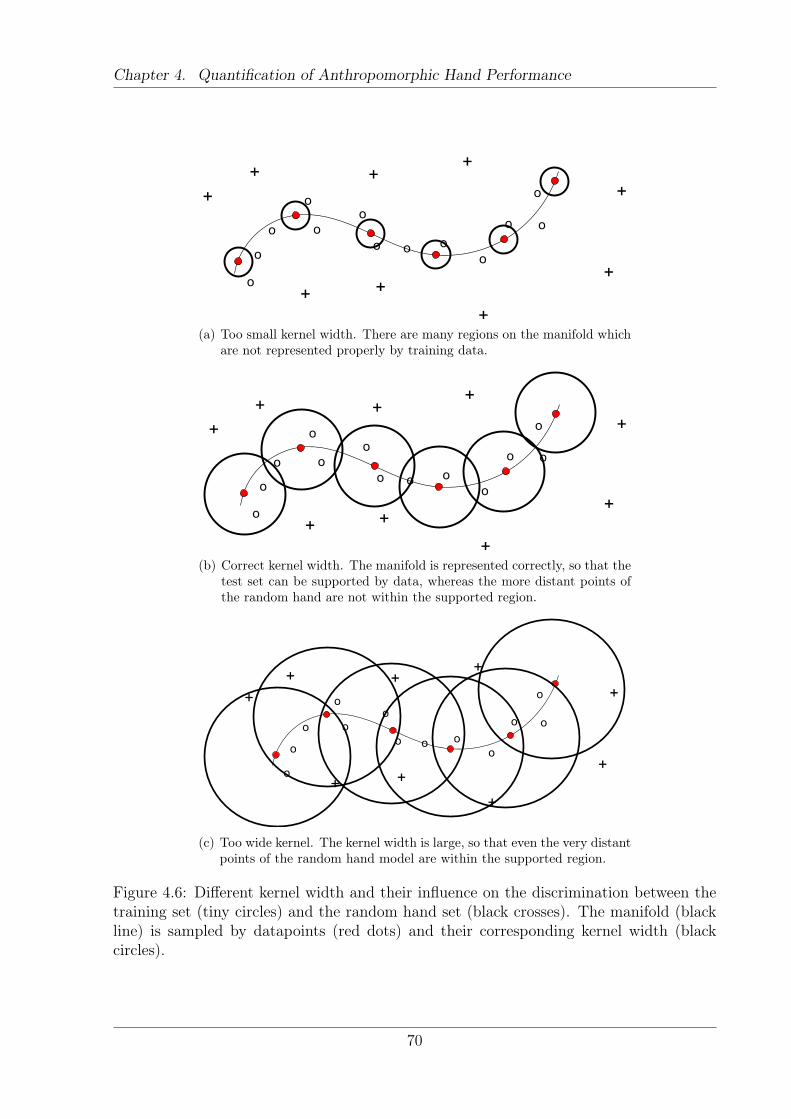
Chapter 4. Quantification of Anthropomorphic Hand Performance
o
+
o
o
o
oo
o o oo
o o
o
+
+ +
+
+
+
+
+
(a) Too small kernel width. There are many regions on the manifold whichare not represented properly by training data.
o
+
o
o
o
oo
o o oo
o o
o
+
+ +
+
+
+
+
+
(b) Correct kernel width. The manifold is represented correctly, so that thetest set can be supported by data, whereas the more distant points ofthe random hand are not within the supported region.
o
+
o
o
o
oo
o o oo
o o
o
+
+ +
+
+
+
+
+
(c) Too wide kernel. The kernel width is large, so that even the very distantpoints of the random hand model are within the supported region.
Figure 4.6: Different kernel width and their influence on the discrimination between thetraining set (tiny circles) and the random hand set (black crosses). The manifold (blackline) is sampled by datapoints (red dots) and their corresponding kernel width (blackcircles).
70
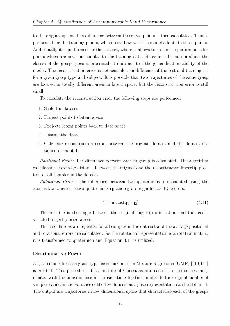
Chapter 4. Quantification of Anthropomorphic Hand Performance
to the original space. The difference between those two points is then calculated. That isperformed for the training points, which tests how well the model adapts to those points.Additionally it is performed for the test set, where it allows to assess the performance forpoints which are new, but similar to the training data. Since no information about theclasses of the grasp types is processed, it does not test the generalization ability of themodel. The reconstruction error is not sensible to a difference of the test and training setfor a given grasp type and subject. It is possible that two trajectories of the same graspare located in totally different areas in latent space, but the reconstruction error is stillsmall.
To calculate the reconstruction error the following steps are performed:
1. Scale the dataset
2. Project points to latent space
3. Projects latent points back to data space
4. Unscale the data
5. Calculate reconstruction errors between the original dataset and the dataset ob-tained in point 4.
Positional Error: The difference between each fingertip is calculated. The algorithmcalculates the average distance between the original and the reconstructed fingertip posi-tion of all samples in the dataset.
Rotational Error: The difference between two quaternions is calculated using thecosines law where the two quaternions q1 and q2 are regarded as 4D vectors.
δ = arccos(q1 · q2) (4.11)
The result δ is the angle between the original fingertip orientation and the recon-structed fingertip orientation.
The calculations are repeated for all samples in the data set and the average positionaland rotational errors are calculated. As the rotational representation is a rotation matrix,it is transformed to quaternion and Equation 4.11 is utilized.
Discriminative Power
A grasp model for each grasp type based on Gaussian Mixture Regression (GMR) [110,111]is created. This procedure fits a mixture of Gaussians into each set of sequences, aug-mented with the time dimension. For each timestep (not limited to the original number ofsamples) a mean and variance of the low dimensional pose representation can be obtained.The output are trajectories in low dimensional space that characterize each of the grasps
71
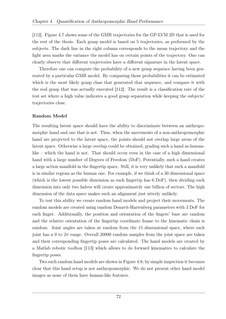
Chapter 4. Quantification of Anthropomorphic Hand Performance
[112]. Figure 4.7 shows some of the GMR trajectories for the GP-LVM 2D that is used forthe rest of the thesis. Each grasp model is based on 5 trajectories, as performed by thesubjects. The dark line in the right column corresponds to the mean trajectory and thelight area marks the variance the model has on certain points of the trajectory. One canclearly observe that different trajectories have a different signature in the latent space.
Therefore one can compute the probability of a new grasp sequence having been gen-erated by a particular GMR model. By comparing those probabilities it can be estimatedwhich is the most likely grasp class that generated that sequence, and compare it withthe real grasp that was actually executed [112]. The result is a classification rate of thetest set where a high value indicates a good grasp separation while keeping the subjects’trajectories close.
Random Model
The resulting latent space should have the ability to discriminate between an anthropo-morphic hand and one that is not. Thus, when the movements of a non-anthropomorphichand are projected to the latent space, the points should not overlap large areas of thelatent space. Otherwise a large overlap could be obtained, grading such a hand as human-like – which the hand is not. That should occur even in the case of a high dimensionalhand with a large number of Degrees of Freedom (DoF). Potentially, such a hand createsa large action manifold in the fingertip space. Still, it is very unlikely that such a manifoldis in similar regions as the human one. For example, if we think of a 30 dimensional space(which is the lowest possible dimension as each fingertip has 6 DoF), then dividing eachdimension into only two halves will create approximately one billion of sectors. The highdimension of the data space makes such an alignment just utterly unlikely.
To test this ability we create random hand models and project their movements. Therandom models are created using random Denavit-Hartenberg parameters with 3 DoF foreach finger. Additionally, the position and orientation of the fingers’ base are randomand the relative orientation of the fingertip coordinate frame to the kinematic chain israndom. Joint angles are taken at random from the 15 dimensional space, where eachjoint has a 0 to 2π range. Overall 20000 random samples from the joint space are takenand their corresponding fingertip poses are calculated. The hand models are created bya Matlab robotic toolbox [113] which allows to do forward kinematics to calculate thefingertip poses.
Two such random hand models are shown in Figure 4.8; by simple inspection it becomesclear that this hand setup is not anthropomorphic. We do not present other hand modelimages as none of them have human-like features.
72
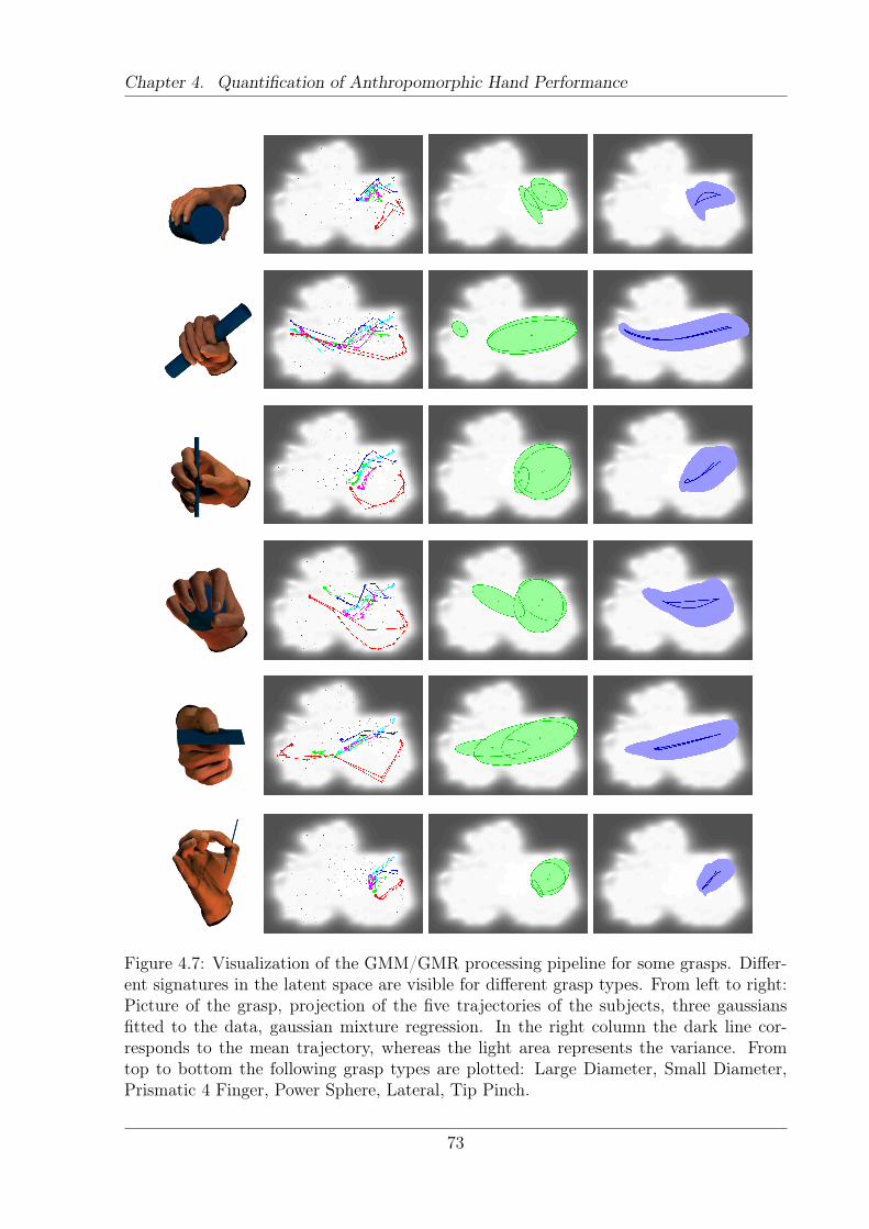
Chapter 4. Quantification of Anthropomorphic Hand Performance
Figure 4.7: Visualization of the GMM/GMR processing pipeline for some grasps. Differ-ent signatures in the latent space are visible for different grasp types. From left to right:Picture of the grasp, projection of the five trajectories of the subjects, three gaussiansfitted to the data, gaussian mixture regression. In the right column the dark line cor-responds to the mean trajectory, whereas the light area represents the variance. Fromtop to bottom the following grasp types are plotted: Large Diameter, Small Diameter,Prismatic 4 Finger, Power Sphere, Lateral, Tip Pinch.
73
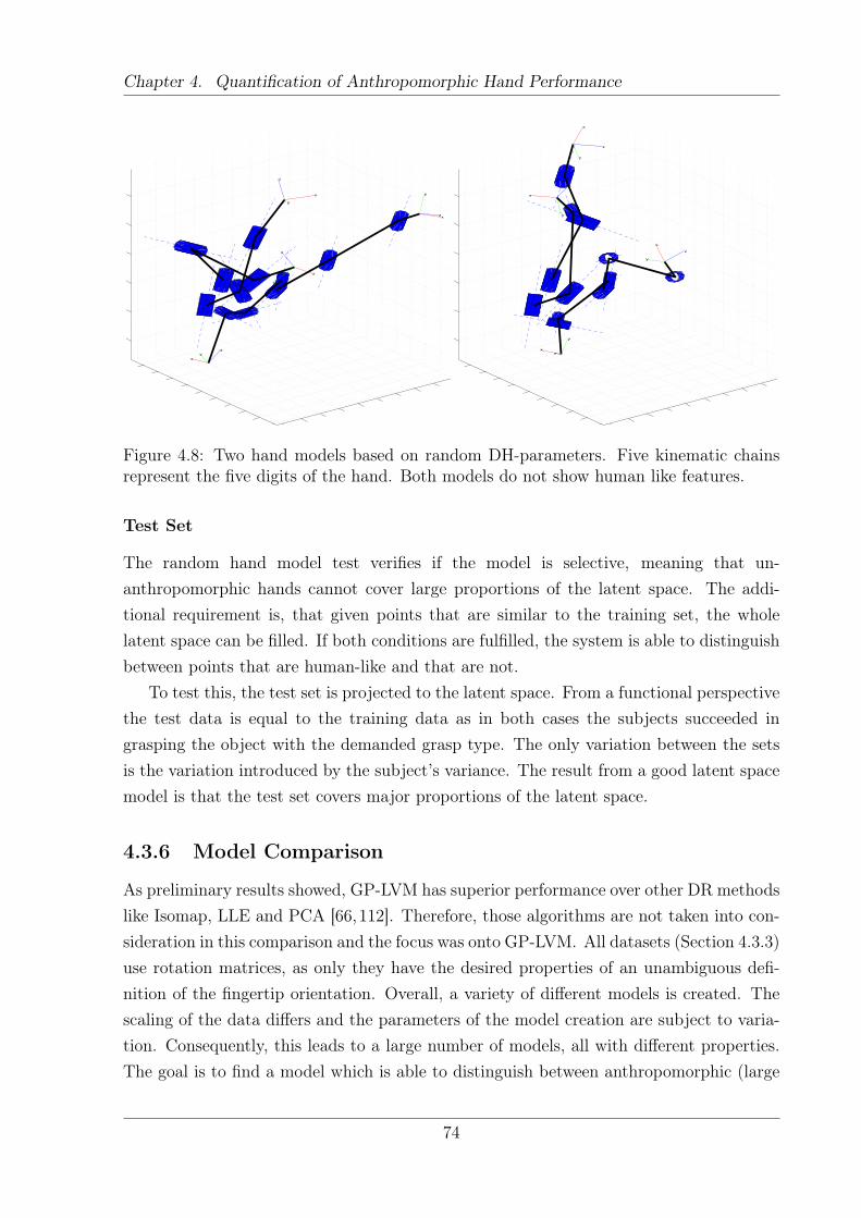
Chapter 4. Quantification of Anthropomorphic Hand Performance
x
y
z
x
yz
x
y
z
x
y
z
x
y
z
x
y
z
x
y
z
x
y
z
Figure 4.8: Two hand models based on random DH-parameters. Five kinematic chainsrepresent the five digits of the hand. Both models do not show human like features.
Test Set
The random hand model test verifies if the model is selective, meaning that un-anthropomorphic hands cannot cover large proportions of the latent space. The addi-tional requirement is, that given points that are similar to the training set, the wholelatent space can be filled. If both conditions are fulfilled, the system is able to distinguishbetween points that are human-like and that are not.
To test this, the test set is projected to the latent space. From a functional perspectivethe test data is equal to the training data as in both cases the subjects succeeded ingrasping the object with the demanded grasp type. The only variation between the setsis the variation introduced by the subject’s variance. The result from a good latent spacemodel is that the test set covers major proportions of the latent space.
4.3.6 Model Comparison
As preliminary results showed, GP-LVM has superior performance over other DR methodslike Isomap, LLE and PCA [66,112]. Therefore, those algorithms are not taken into con-sideration in this comparison and the focus was onto GP-LVM. All datasets (Section 4.3.3)use rotation matrices, as only they have the desired properties of an unambiguous defi-nition of the fingertip orientation. Overall, a variety of different models is created. Thescaling of the data differs and the parameters of the model creation are subject to varia-tion. Consequently, this leads to a large number of models, all with different properties.The goal is to find a model which is able to distinguish between anthropomorphic (large
74
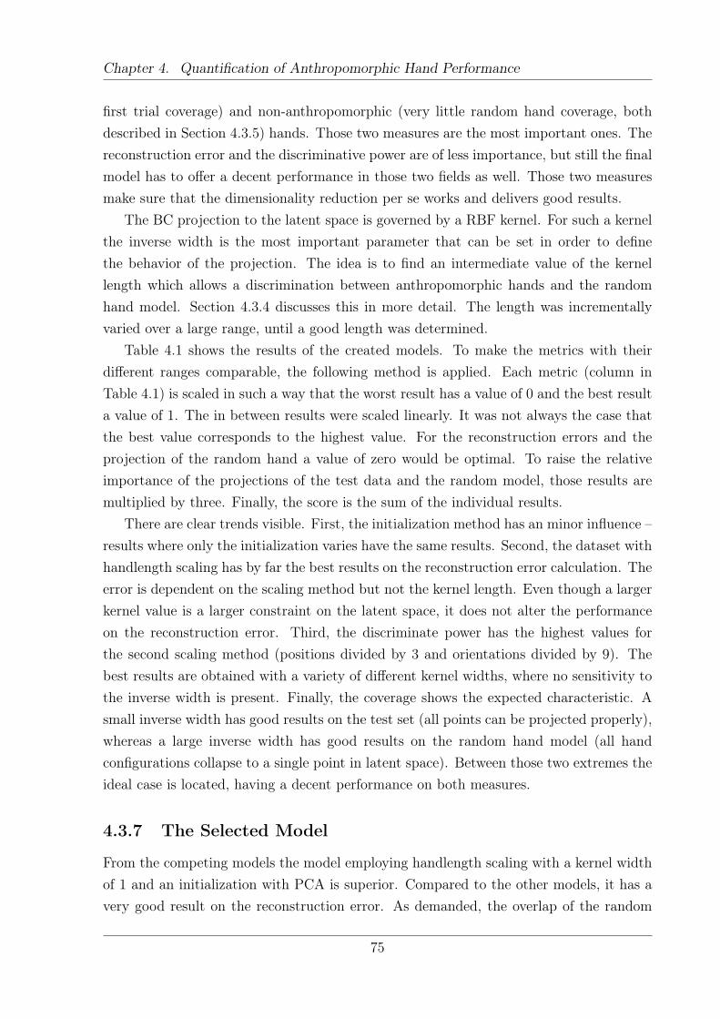
Chapter 4. Quantification of Anthropomorphic Hand Performance
first trial coverage) and non-anthropomorphic (very little random hand coverage, bothdescribed in Section 4.3.5) hands. Those two measures are the most important ones. Thereconstruction error and the discriminative power are of less importance, but still the finalmodel has to offer a decent performance in those two fields as well. Those two measuresmake sure that the dimensionality reduction per se works and delivers good results.
The BC projection to the latent space is governed by a RBF kernel. For such a kernelthe inverse width is the most important parameter that can be set in order to definethe behavior of the projection. The idea is to find an intermediate value of the kernellength which allows a discrimination between anthropomorphic hands and the randomhand model. Section 4.3.4 discusses this in more detail. The length was incrementallyvaried over a large range, until a good length was determined.
Table 4.1 shows the results of the created models. To make the metrics with theirdifferent ranges comparable, the following method is applied. Each metric (column inTable 4.1) is scaled in such a way that the worst result has a value of 0 and the best resulta value of 1. The in between results were scaled linearly. It was not always the case thatthe best value corresponds to the highest value. For the reconstruction errors and theprojection of the random hand a value of zero would be optimal. To raise the relativeimportance of the projections of the test data and the random model, those results aremultiplied by three. Finally, the score is the sum of the individual results.
There are clear trends visible. First, the initialization method has an minor influence –results where only the initialization varies have the same results. Second, the dataset withhandlength scaling has by far the best results on the reconstruction error calculation. Theerror is dependent on the scaling method but not the kernel length. Even though a largerkernel value is a larger constraint on the latent space, it does not alter the performanceon the reconstruction error. Third, the discriminate power has the highest values forthe second scaling method (positions divided by 3 and orientations divided by 9). Thebest results are obtained with a variety of different kernel widths, where no sensitivity tothe inverse width is present. Finally, the coverage shows the expected characteristic. Asmall inverse width has good results on the test set (all points can be projected properly),whereas a large inverse width has good results on the random hand model (all handconfigurations collapse to a single point in latent space). Between those two extremes theideal case is located, having a decent performance on both measures.
4.3.7 The Selected Model
From the competing models the model employing handlength scaling with a kernel widthof 1 and an initialization with PCA is superior. Compared to the other models, it has avery good result on the reconstruction error. As demanded, the overlap of the random
75
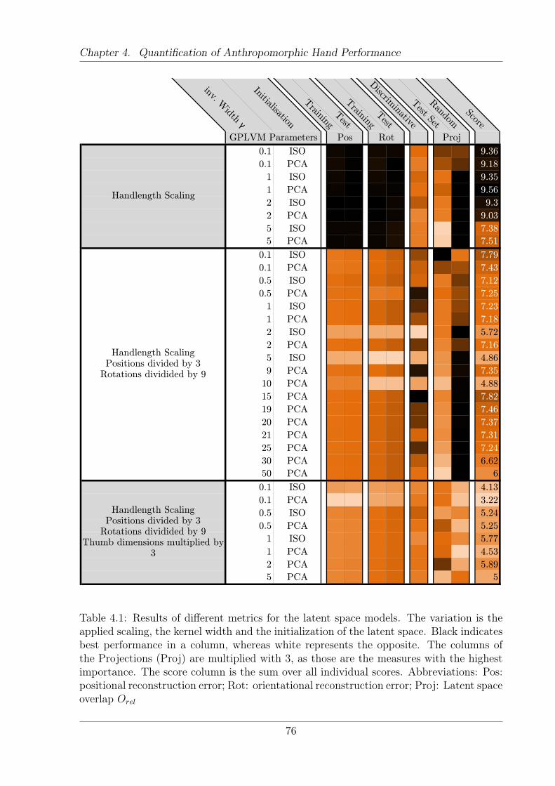
Chapter 4. Quantification of Anthropomorphic Hand Performance
inv. Width γ
Initialisation
Training
Test
Training
Test
Discrim
inative
Test Set
Random
Score
ProjGPLVM Parameters Pos Rot
0.1 ISO 9.36
0.1 PCA 9.18
1 ISO 9.35
1 PCA 9.56
2 ISO 9.3
2 PCA 9.03
5 ISO 7.38
5 PCA 7.51
0.1 ISO 7.79
0.1 PCA 7.43
0.5 ISO 7.12
0.5 PCA 7.25
1 ISO 7.23
1 PCA 7.18
2 ISO 5.72
2 PCA 7.16
5 ISO 4.86
9 PCA 7.35
10 PCA 4.88
15 PCA 7.82
19 PCA 7.46
20 PCA 7.37
21 PCA 7.31
25 PCA 7.24
30 PCA 6.62
50 PCA 6
0.1 ISO 4.13
0.1 PCA 3.22
0.5 ISO 5.24
0.5 PCA 5.25
1 ISO 5.77
1 PCA 4.53
2 PCA 5.89
5 PCA 5
Proj
Handlength Scaling
Handlength ScalingPositions divided by 3Rotations dividided by 9
Handlength ScalingPositions divided by 3Rotations dividided by 9
Thumb dimensions multiplied by 3
GPLVM Parameters Pos Rot
Table 4.1: Results of different metrics for the latent space models. The variation is theapplied scaling, the kernel width and the initialization of the latent space. Black indicatesbest performance in a column, whereas white represents the opposite. The columns ofthe Projections (Proj) are multiplied with 3, as those are the measures with the highestimportance. The score column is the sum over all individual scores. Abbreviations: Pos:positional reconstruction error; Rot: orientational reconstruction error; Proj: Latent spaceoverlap Orel
76
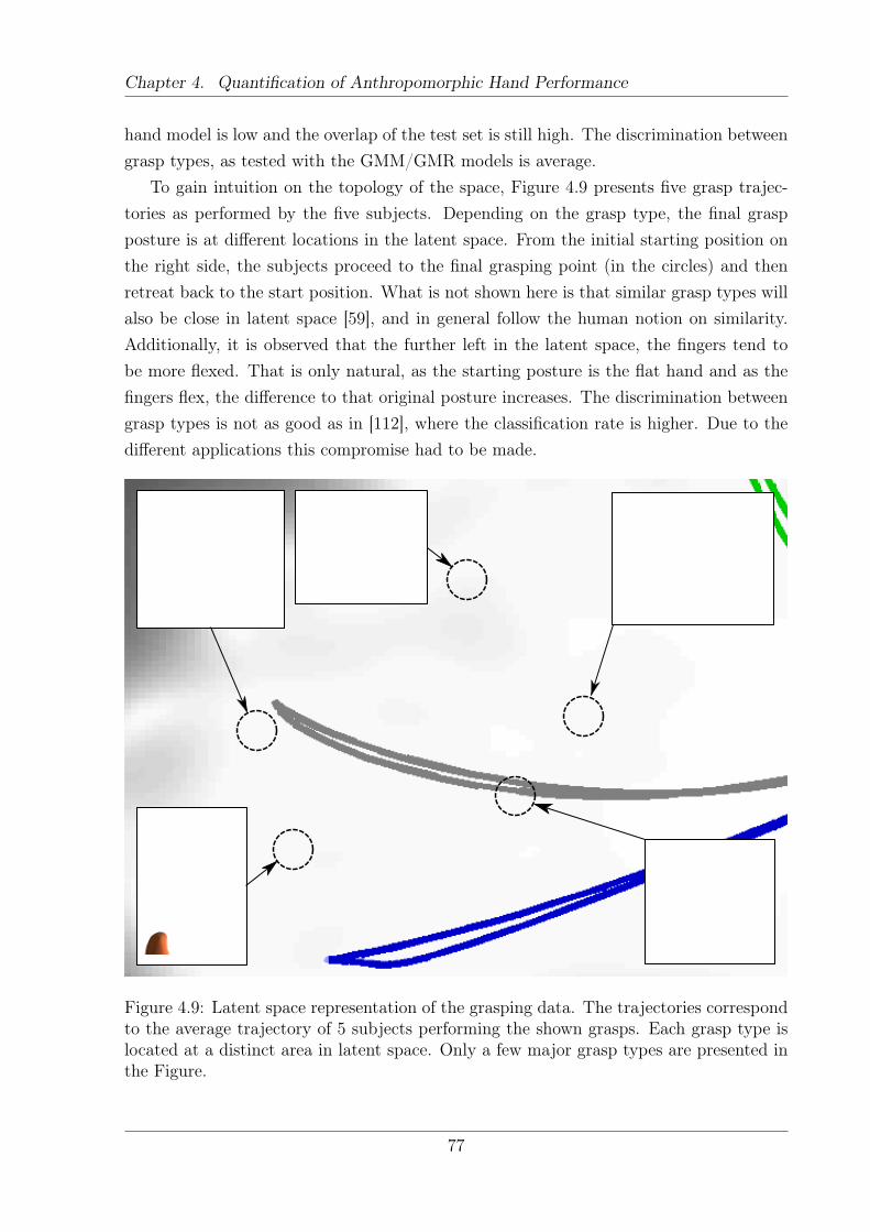
Chapter 4. Quantification of Anthropomorphic Hand Performance
hand model is low and the overlap of the test set is still high. The discrimination betweengrasp types, as tested with the GMM/GMR models is average.
To gain intuition on the topology of the space, Figure 4.9 presents five grasp trajec-tories as performed by the five subjects. Depending on the grasp type, the final graspposture is at different locations in the latent space. From the initial starting position onthe right side, the subjects proceed to the final grasping point (in the circles) and thenretreat back to the start position. What is not shown here is that similar grasp types willalso be close in latent space [59], and in general follow the human notion on similarity.Additionally, it is observed that the further left in the latent space, the fingers tend tobe more flexed. That is only natural, as the starting posture is the flat hand and as thefingers flex, the difference to that original posture increases. The discrimination betweengrasp types is not as good as in [112], where the classification rate is higher. Due to thedifferent applications this compromise had to be made.
Figure 4.9: Latent space representation of the grasping data. The trajectories correspondto the average trajectory of 5 subjects performing the shown grasps. Each grasp type islocated at a distinct area in latent space. Only a few major grasp types are presented inthe Figure.
77
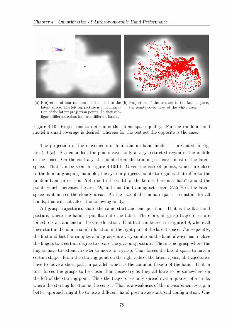
Chapter 4. Quantification of Anthropomorphic Hand Performance
(a) Projection of four random hand models to thelatent space. The left top picture is a magnifica-tion of the latent projection points. In that sub-figure different colors indicate different hands.
(b) Projection of the test set to the latent space,the points cover most of the white area.
Figure 4.10: Projections to determine the latent space quality. For the random handmodel a small coverage is desired, whereas for the test set the opposite is the case.
The projection of the movements of four random hand models is presented in Fig-ure 4.10(a). As demanded, the points cover only a very restricted region in the middleof the space. On the contrary, the points from the training set cover most of the latentspace. That can be seen in Figure 4.10(b). Given the correct points, which are closeto the human grasping manifold, the system projects points to regions that differ to therandom hand projection. Yet, due to the width of the kernel there is a “halo” around thepoints which increases the area Oh and thus the training set covers 52.5 % of the latentspace as it misses the cloudy areas. As the size of the human space is constant for allhands, this will not affect the following analysis.
All grasp trajectories share the same start and end position. That is the flat handposture, where the hand is put flat onto the table. Therefore, all grasp trajectories areforced to start and end at the same location. That fact can be seen in Figure 4.9, where alllines start and end in a similar location in the right part of the latent space. Consequently,the first and last few samples of all grasps are very similar as the hand always has to closethe fingers to a certain degree to create the grasping posture. There is no grasp where thefingers have to extend in order to move to a grasp. That forces the latent space to have acertain shape. From the starting point on the right side of the latent space, all trajectorieshave to move a short path in parallel, which is the common flexion of the hand. That inturn forces the grasps to be closer than necessary as they all have to be somewhere onthe left of the starting point. Thus the trajectories only spread over a quarter of a circle,where the starting location is the center. That is a weakness of the measurement setup; abetter approach might be to use a different hand posture as start/end configuration. One
78
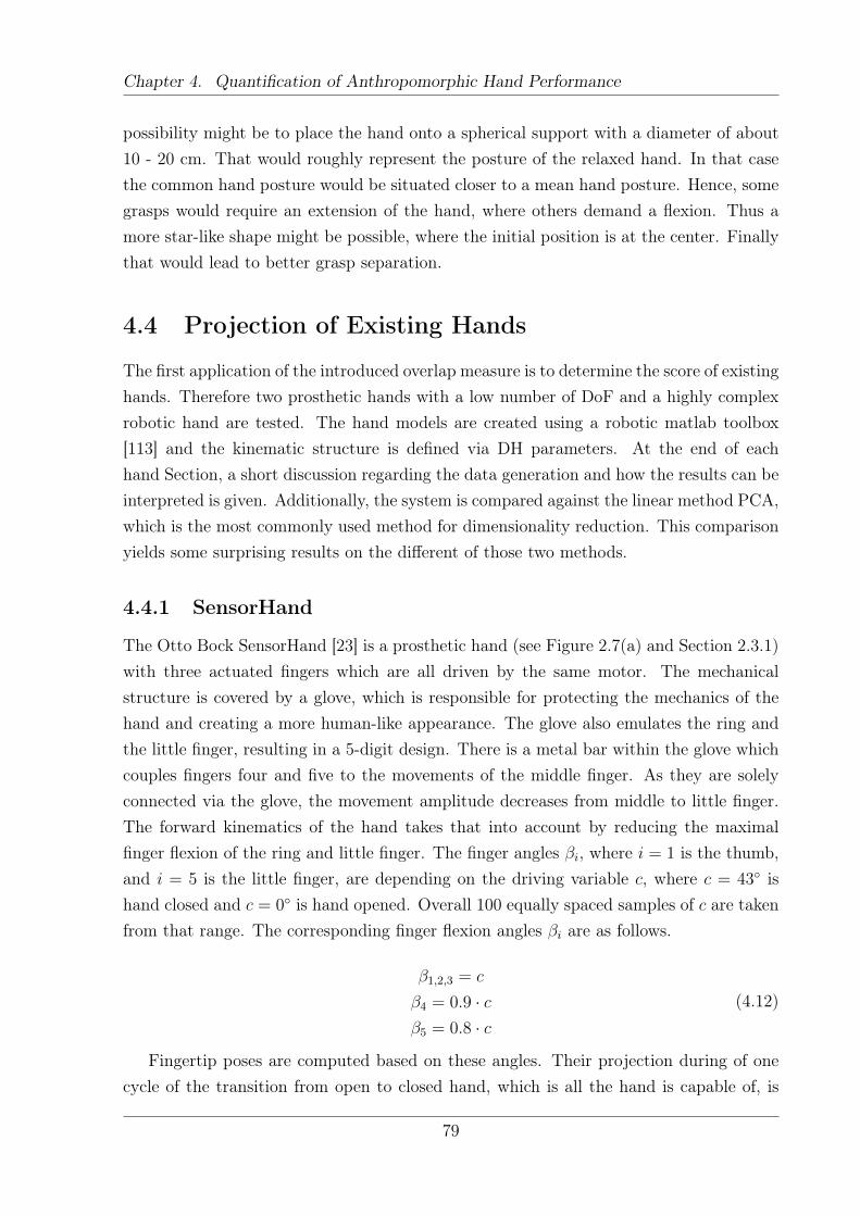
Chapter 4. Quantification of Anthropomorphic Hand Performance
possibility might be to place the hand onto a spherical support with a diameter of about10 - 20 cm. That would roughly represent the posture of the relaxed hand. In that casethe common hand posture would be situated closer to a mean hand posture. Hence, somegrasps would require an extension of the hand, where others demand a flexion. Thus amore star-like shape might be possible, where the initial position is at the center. Finallythat would lead to better grasp separation.
4.4 Projection of Existing Hands
The first application of the introduced overlap measure is to determine the score of existinghands. Therefore two prosthetic hands with a low number of DoF and a highly complexrobotic hand are tested. The hand models are created using a robotic matlab toolbox[113] and the kinematic structure is defined via DH parameters. At the end of eachhand Section, a short discussion regarding the data generation and how the results can beinterpreted is given. Additionally, the system is compared against the linear method PCA,which is the most commonly used method for dimensionality reduction. This comparisonyields some surprising results on the different of those two methods.
4.4.1 SensorHand
The Otto Bock SensorHand [23] is a prosthetic hand (see Figure 2.7(a) and Section 2.3.1)with three actuated fingers which are all driven by the same motor. The mechanicalstructure is covered by a glove, which is responsible for protecting the mechanics of thehand and creating a more human-like appearance. The glove also emulates the ring andthe little finger, resulting in a 5-digit design. There is a metal bar within the glove whichcouples fingers four and five to the movements of the middle finger. As they are solelyconnected via the glove, the movement amplitude decreases from middle to little finger.The forward kinematics of the hand takes that into account by reducing the maximalfinger flexion of the ring and little finger. The finger angles βi, where i = 1 is the thumb,and i = 5 is the little finger, are depending on the driving variable c, where c = 43◦ ishand closed and c = 0◦ is hand opened. Overall 100 equally spaced samples of c are takenfrom that range. The corresponding finger flexion angles βi are as follows.
β1,2,3 = c
β4 = 0.9 · cβ5 = 0.8 · c
(4.12)
Fingertip poses are computed based on these angles. Their projection during of onecycle of the transition from open to closed hand, which is all the hand is capable of, is
79
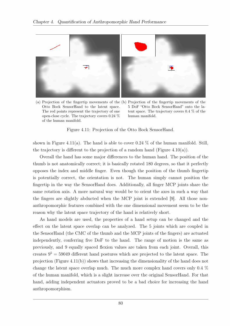
Chapter 4. Quantification of Anthropomorphic Hand Performance
(a) Projection of the fingertip movements of theOtto Bock SensorHand to the latent space.The red points represent the trajectory of oneopen-close cycle. The trajectory covers 0.24 %of the human manifold.
(b) Projection of the fingertip movements of the5 DoF “Otto Bock SensorHand” onto the la-tent space. The trajectory covers 0.4 % of thehuman manifold.
Figure 4.11: Projection of the Otto Bock SensorHand.
shown in Figure 4.11(a). The hand is able to cover 0.24 % of the human manifold. Still,the trajectory is different to the projection of a random hand (Figure 4.10(a)).
Overall the hand has some major differences to the human hand. The position of thethumb is not anatomically correct; it is basically rotated 180 degrees, so that it perfectlyopposes the index and middle finger. Even though the position of the thumb fingertipis potentially correct, the orientation is not. The human simply cannot position thefingertip in the way the SensorHand does. Additionally, all finger MCP joints share thesame rotation axis. A more natural way would be to orient the axes in such a way thatthe fingers are slightly abducted when the MCP joint is extended [9]. All those non-anthropomorphic features combined with the one dimensional movement seem to be thereason why the latent space trajectory of the hand is relatively short.
As hand models are used, the properties of a hand setup can be changed and theeffect on the latent space overlap can be analyzed. The 5 joints which are coupled inthe SensorHand (the CMC of the thumb and the MCP joints of the fingers) are actuatedindependently, conferring five DoF to the hand. The range of motion is the same aspreviously, and 9 equally spaced flexion values are taken from each joint. Overall, thiscreates 95 = 59049 different hand postures which are projected to the latent space. Theprojection (Figure 4.11(b)) shows that increasing the dimensionality of the hand does notchange the latent space overlap much. The much more complex hand covers only 0.4 %of the human manifold, which is a slight increase over the original SensorHand. For thathand, adding independent actuators proved to be a bad choice for increasing the handanthropomorphism.
80
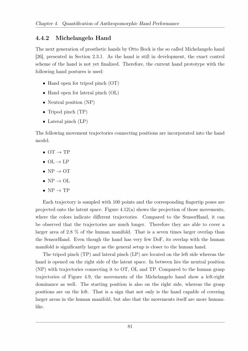
Chapter 4. Quantification of Anthropomorphic Hand Performance
4.4.2 Michelangelo Hand
The next generation of prosthetic hands by Otto Bock is the so called Michelangelo hand[26], presented in Section 2.3.1. As the hand is still in development, the exact controlscheme of the hand is not yet finalized. Therefore, the current hand prototype with thefollowing hand postures is used:
• Hand open for tripod pinch (OT)
• Hand open for lateral pinch (OL)
• Neutral position (NP)
• Tripod pinch (TP)
• Lateral pinch (LP)
The following movement trajectories connecting positions are incorporated into the handmodel.
• OT → TP
• OL → LP
• NP → OT
• NP → OL
• NP → TP
Each trajectory is sampled with 100 points and the corresponding fingertip poses areprojected onto the latent space. Figure 4.12(a) shows the projection of those movements,where the colors indicate different trajectories. Compared to the SensorHand, it canbe observed that the trajectories are much longer. Therefore they are able to cover alarger area of 2.8 % of the human manifold. That is a seven times larger overlap thanthe SensorHand. Even though the hand has very few DoF, its overlap with the humanmanifold is significantly larger as the general setup is closer to the human hand.
The tripod pinch (TP) and lateral pinch (LP) are located on the left side whereas thehand is opened on the right side of the latent space. In between lies the neutral position(NP) with trajectories connecting it to OT, OL and TP. Compared to the human grasptrajectories of Figure 4.9, the movements of the Michelangelo hand show a left-rightdominance as well. The starting position is also on the right side, whereas the grasppositions are on the left. That is a sign that not only is the hand capable of coveringlarger areas in the human manifold, but also that the movements itself are more human-like.
81

Chapter 4. Quantification of Anthropomorphic Hand Performance
The positions of the tripod pinch and the lateral pinch are relatively close in latentspace. The reason seems to be that the system is weighting every finger roughly the same.
As the poses of four of the five digits are nearly identical (in the lateral pinch thefingers flex a little bit more), it is plausible that the projections in the latent space aresimilar.
As described above, the Michelangelo hand is controlled by choosing different trajecto-ries, along which the hand is controlled as being one-dimensional. That step is necessaryas the controller (as described in Section 2.3.3) of the prosthetic hand lacks a proper wayto control the full two DoF of the hand. In the remainder of the thesis, the Michelangelohand is used as the starting point for further hand optimizations. As the goal is to de-termine the mechanical potential of the hand, not the potential influenced by a certaincontrol scheme, the full two dimensional hand is taken into account. Therefore all possi-ble digit flexion and thumb abduction values are calculated and projected. The resultingoverlap can be seen in Figure 4.12(b), where the resulting overlap is 3.9 %. That numberwill serve as the baseline for all further analysis.
As already done with the SensorHand, the complexity of the hand is increased byassigning the hand 5 DoF – the flexion of each digit is actuated independently. As thethumb has an additional DoF (abduction/adduction) this value has to be specified aswell. It is set into the intermediate rest position. Changing the value of this joint doesnot affect significantly the results. The range of motion from each digit is sampled with 9angles, resulting in the same number of points as in the SensorHand case. The resultingoverlap is 7.9 %, which is considerably more than the 2.8 % the original hand has. Inthat case it seems that introducing additional DoFs is a suitable way to equip the handwith more anthropomorphic capabilities. In the projection of the 5 DoF Michelangeloin Figure 4.12(c), it becomes visible that the extreme position in the right-left directioncorresponds to the open and the grasp position respectively. All movements of the originalMichelangelo lie beneath the line connecting those two positions and have very roughlya triangle shape. The movements of the 5 DoF hand overlap an additional space abovethat triangle. The top point in the projection in Figure 4.12(c) corresponds to a handposition where the index finger is extended but the other fingers are flexed and the thumbis in moderate flexion. The ability to individually flex fingers seems to be importantto reach new areas in the latent space. That is a difference to the SensorHand wherethe introduction of finger individuation does not influence substantially the latent spaceoverlap.
82
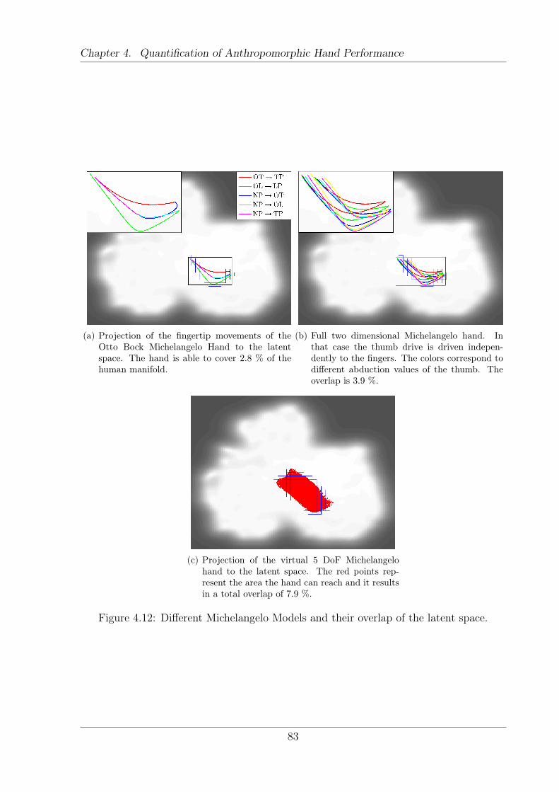
Chapter 4. Quantification of Anthropomorphic Hand Performance
(a) Projection of the fingertip movements of theOtto Bock Michelangelo Hand to the latentspace. The hand is able to cover 2.8 % of thehuman manifold.
(b) Full two dimensional Michelangelo hand. Inthat case the thumb drive is driven indepen-dently to the fingers. The colors correspond todifferent abduction values of the thumb. Theoverlap is 3.9 %.
(c) Projection of the virtual 5 DoF Michelangelohand to the latent space. The red points rep-resent the area the hand can reach and it resultsin a total overlap of 7.9 %.
Figure 4.12: Different Michelangelo Models and their overlap of the latent space.
83
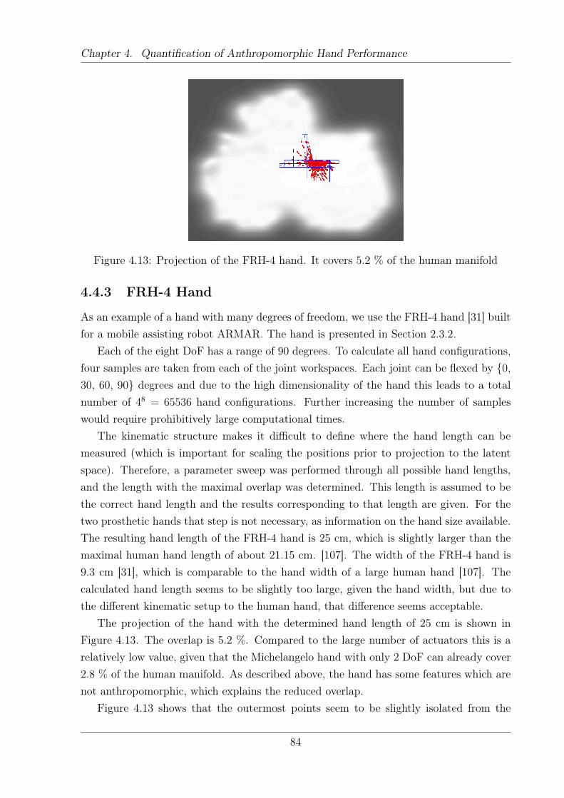
Chapter 4. Quantification of Anthropomorphic Hand Performance
Figure 4.13: Projection of the FRH-4 hand. It covers 5.2 % of the human manifold
4.4.3 FRH-4 Hand
As an example of a hand with many degrees of freedom, we use the FRH-4 hand [31] builtfor a mobile assisting robot ARMAR. The hand is presented in Section 2.3.2.
Each of the eight DoF has a range of 90 degrees. To calculate all hand configurations,four samples are taken from each of the joint workspaces. Each joint can be flexed by {0,30, 60, 90} degrees and due to the high dimensionality of the hand this leads to a totalnumber of 48 = 65536 hand configurations. Further increasing the number of sampleswould require prohibitively large computational times.
The kinematic structure makes it difficult to define where the hand length can bemeasured (which is important for scaling the positions prior to projection to the latentspace). Therefore, a parameter sweep was performed through all possible hand lengths,and the length with the maximal overlap was determined. This length is assumed to bethe correct hand length and the results corresponding to that length are given. For thetwo prosthetic hands that step is not necessary, as information on the hand size available.The resulting hand length of the FRH-4 hand is 25 cm, which is slightly larger than themaximal human hand length of about 21.15 cm. [107]. The width of the FRH-4 hand is9.3 cm [31], which is comparable to the hand width of a large human hand [107]. Thecalculated hand length seems to be slightly too large, given the hand width, but due tothe different kinematic setup to the human hand, that difference seems acceptable.
The projection of the hand with the determined hand length of 25 cm is shown inFigure 4.13. The overlap is 5.2 %. Compared to the large number of actuators this is arelatively low value, given that the Michelangelo hand with only 2 DoF can already cover2.8 % of the human manifold. As described above, the hand has some features which arenot anthropomorphic, which explains the reduced overlap.
Figure 4.13 shows that the outermost points seem to be slightly isolated from the
84
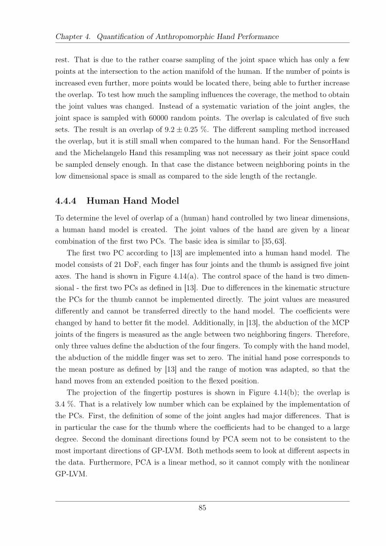
Chapter 4. Quantification of Anthropomorphic Hand Performance
rest. That is due to the rather coarse sampling of the joint space which has only a fewpoints at the intersection to the action manifold of the human. If the number of points isincreased even further, more points would be located there, being able to further increasethe overlap. To test how much the sampling influences the coverage, the method to obtainthe joint values was changed. Instead of a systematic variation of the joint angles, thejoint space is sampled with 60000 random points. The overlap is calculated of five suchsets. The result is an overlap of 9.2 ± 0.25 %. The different sampling method increasedthe overlap, but it is still small when compared to the human hand. For the SensorHandand the Michelangelo Hand this resampling was not necessary as their joint space couldbe sampled densely enough. In that case the distance between neighboring points in thelow dimensional space is small as compared to the side length of the rectangle.
4.4.4 Human Hand Model
To determine the level of overlap of a (human) hand controlled by two linear dimensions,a human hand model is created. The joint values of the hand are given by a linearcombination of the first two PCs. The basic idea is similar to [35,63].
The first two PC according to [13] are implemented into a human hand model. Themodel consists of 21 DoF, each finger has four joints and the thumb is assigned five jointaxes. The hand is shown in Figure 4.14(a). The control space of the hand is two dimen-sional - the first two PCs as defined in [13]. Due to differences in the kinematic structurethe PCs for the thumb cannot be implemented directly. The joint values are measureddifferently and cannot be transferred directly to the hand model. The coefficients werechanged by hand to better fit the model. Additionally, in [13], the abduction of the MCPjoints of the fingers is measured as the angle between two neighboring fingers. Therefore,only three values define the abduction of the four fingers. To comply with the hand model,the abduction of the middle finger was set to zero. The initial hand pose corresponds tothe mean posture as defined by [13] and the range of motion was adapted, so that thehand moves from an extended position to the flexed position.
The projection of the fingertip postures is shown in Figure 4.14(b); the overlap is3.4 %. That is a relatively low number which can be explained by the implementation ofthe PCs. First, the definition of some of the joint angles had major differences. That isin particular the case for the thumb where the coefficients had to be changed to a largedegree. Second the dominant directions found by PCA seem not to be consistent to themost important directions of GP-LVM. Both methods seem to look at different aspects inthe data. Furthermore, PCA is a linear method, so it cannot comply with the nonlinearGP-LVM.
85
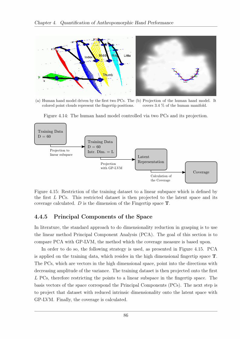
Chapter 4. Quantification of Anthropomorphic Hand Performance
(a) Human hand model driven by the first two PCs. Thecolored point clouds represent the fingertip positions.
(b) Projection of the human hand model. Itcovers 3.4 % of the human manifold.
Figure 4.14: The human hand model controlled via two PCs and its projection.
Training Data
D = 60
Training Data
D = 60
Intr. Dim. = L
Latent
Representation
Projection to
linear subspace
Projection
with GP-LVM
CoverageCalculation of
the Coverage
Figure 4.15: Restriction of the training dataset to a linear subspace which is defined bythe first L PCs. This restricted dataset is then projected to the latent space and itscoverage calculated. D is the dimension of the Fingertip space T.
4.4.5 Principal Components of the Space
In literature, the standard approach to do dimensionality reduction in grasping is to usethe linear method Principal Component Analysis (PCA). The goal of this section is tocompare PCA with GP-LVM, the method which the coverage measure is based upon.
In order to do so, the following strategy is used, as presented in Figure 4.15. PCAis applied on the training data, which resides in the high dimensional fingertip space T.The PCs, which are vectors in the high dimensional space, point into the directions withdecreasing amplitude of the variance. The training dataset is then projected onto the firstL PCs, therefore restricting the points to a linear subspace in the fingertip space. Thebasis vectors of the space correspond the Principal Components (PCs). The next step isto project that dataset with reduced intrinsic dimensionality onto the latent space withGP-LVM. Finally, the coverage is calculated.
86
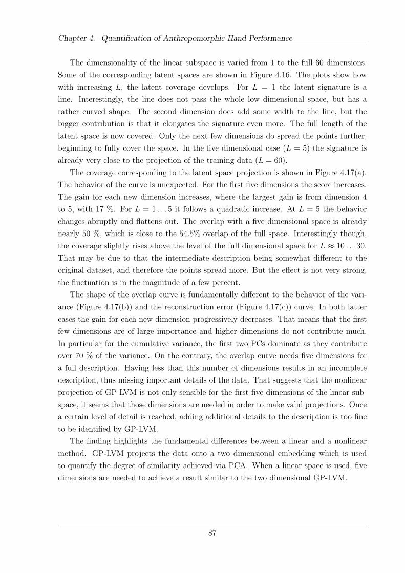
Chapter 4. Quantification of Anthropomorphic Hand Performance
The dimensionality of the linear subspace is varied from 1 to the full 60 dimensions.Some of the corresponding latent spaces are shown in Figure 4.16. The plots show howwith increasing L, the latent coverage develops. For L = 1 the latent signature is aline. Interestingly, the line does not pass the whole low dimensional space, but has arather curved shape. The second dimension does add some width to the line, but thebigger contribution is that it elongates the signature even more. The full length of thelatent space is now covered. Only the next few dimensions do spread the points further,beginning to fully cover the space. In the five dimensional case (L = 5) the signature isalready very close to the projection of the training data (L = 60).
The coverage corresponding to the latent space projection is shown in Figure 4.17(a).The behavior of the curve is unexpected. For the first five dimensions the score increases.The gain for each new dimension increases, where the largest gain is from dimension 4to 5, with 17 %. For L = 1 . . . 5 it follows a quadratic increase. At L = 5 the behaviorchanges abruptly and flattens out. The overlap with a five dimensional space is alreadynearly 50 %, which is close to the 54.5% overlap of the full space. Interestingly though,the coverage slightly rises above the level of the full dimensional space for L ≈ 10 . . . 30.That may be due to that the intermediate description being somewhat different to theoriginal dataset, and therefore the points spread more. But the effect is not very strong,the fluctuation is in the magnitude of a few percent.
The shape of the overlap curve is fundamentally different to the behavior of the vari-ance (Figure 4.17(b)) and the reconstruction error (Figure 4.17(c)) curve. In both lattercases the gain for each new dimension progressively decreases. That means that the firstfew dimensions are of large importance and higher dimensions do not contribute much.In particular for the cumulative variance, the first two PCs dominate as they contributeover 70 % of the variance. On the contrary, the overlap curve needs five dimensions fora full description. Having less than this number of dimensions results in an incompletedescription, thus missing important details of the data. That suggests that the nonlinearprojection of GP-LVM is not only sensible for the first five dimensions of the linear sub-space, it seems that those dimensions are needed in order to make valid projections. Oncea certain level of detail is reached, adding additional details to the description is too fineto be identified by GP-LVM.
The finding highlights the fundamental differences between a linear and a nonlinearmethod. GP-LVM projects the data onto a two dimensional embedding which is usedto quantify the degree of similarity achieved via PCA. When a linear space is used, fivedimensions are needed to achieve a result similar to the two dimensional GP-LVM.
87
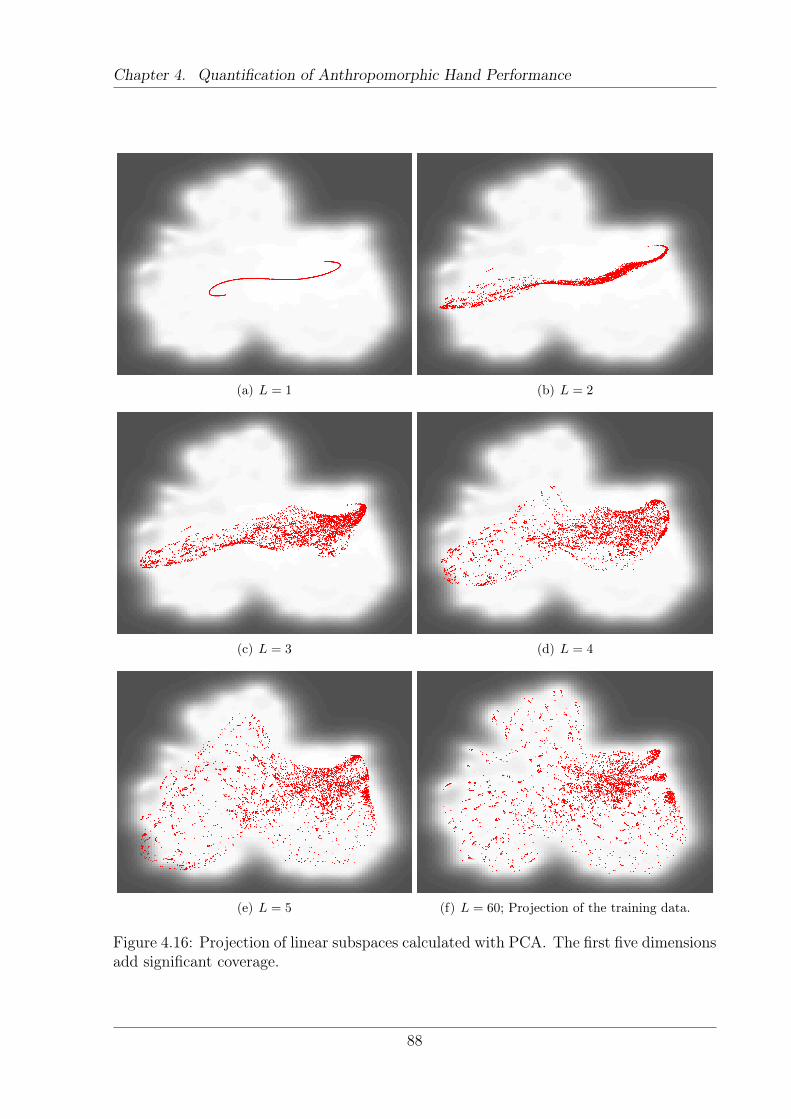
Chapter 4. Quantification of Anthropomorphic Hand Performance
(a) L = 1 (b) L = 2
(c) L = 3 (d) L = 4
(e) L = 5 (f) L = 60; Projection of the training data.
Figure 4.16: Projection of linear subspaces calculated with PCA. The first five dimensionsadd significant coverage.
88
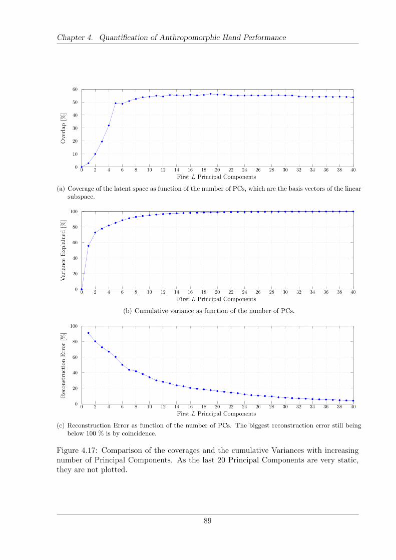
Chapter 4. Quantification of Anthropomorphic Hand Performance
First L Principal Components
Overlap[%
]
0 2 4 6 8 10 12 14 16 18 20 22 24 26 28 30 32 34 36 38 400
10
20
30
40
50
60
(a) Coverage of the latent space as function of the number of PCs, which are the basis vectors of the linearsubspace.
First L Principal Components
Variance
Explained
[%]
0 2 4 6 8 10 12 14 16 18 20 22 24 26 28 30 32 34 36 38 400
20
40
60
80
100
(b) Cumulative variance as function of the number of PCs.
First L Principal Components
ReconstructionError[%
]
0 2 4 6 8 10 12 14 16 18 20 22 24 26 28 30 32 34 36 38 400
20
40
60
80
100
(c) Reconstruction Error as function of the number of PCs. The biggest reconstruction error still beingbelow 100 % is by coincidence.
Figure 4.17: Comparison of the coverages and the cumulative Variances with increasingnumber of Principal Components. As the last 20 Principal Components are very static,they are not plotted.
89
Chapter 4. Quantification of Anthropomorphic Hand Performance
4.5 Discussion
The presented method is an attempt to quantify the capabilities of an anthropomorphichand prior to realization. One big advantage of the system is that the proposed measurecan be applied to a broad range of different hands. The only condition is to use a five-fingered hand. The input to the measure is a kinematic hand model, which defines allfingertip postures it can reach - its action manifold. In the thesis this set was obtainedusing a kinematic hand model implemented via the robotics toolbox [113]. The fingertippostures are obtained by forward kinematics. The type of couplings between fingers andhow the DoF move the joints can be of arbitrary type. There is no need to have linearcouplings for example. They can be based on nonlinear functions or be hard coded.That manifold is compared to the human one, arguing that a large overlap results inan anthropomorphic hand design. To make the comparison feasible, both manifolds areprojected to a common two dimensional space where such a comparison is possible.
The proposed overlap metric solely looks for the similarity in the fingertip postures,not for functional requirements. Consequently, a hand with hand shapes similar to thehuman will be given a high score. It could be that the fingers never touch each other,what actually is important for some grasps. Still, it is a prerequisite for anthropomorphichand function that the fingertip postures are similar. At the current state, the resultsfrom the tested hands look promising and follow the intuition of the author. Yet, thoseresults have not been tested in reality to confirm the results. Additionally, the measureonly processes snapshots of grasp postures, without processing time and dynamics of agrasp. In order to grasp properly, not only the final grasp posture is important, but alsothe opening and closing of the hand. At the moment a large score does not guaranteeproper grasp trajectories. One possible way to overcome this limitation is to add a layerthat processes the open-close trajectories of an artificial hand. If those are parallel tothe human grasp trajectories the score should be higher than in the case of perpendiculartrajectories.
In the current implementation, all digits have the same importance, irrespective ofthe fingers involved in a specific grasp. If a finger is not involved in one grasp, it canbe arbitrarily positioned without affecting the quality of the grasp. One example is the“adduction grasp”, where an object is put between the index and middle finger. Somesubjects closed the remaining fingers, whereas others extended them. That results in alarge difference in the grasp dataset, even if the grasps are very similar from a functionalperspective. At the moment that problem persists within the system. Therefore it mightbe beneficial to add a layer that processes the information on which fingers are in contactwith the object. Such a layer could define which fingers are of relevance for specific graspsand exclude others. Additional work is needed in order to find a feasible solution for this
90
Chapter 4. Quantification of Anthropomorphic Hand Performance
question. Another way would be to restrict the grasping dataset to grasps which employall five fingers, but that excludes many grasp types.
As the method only depends on kinematic hand models, it is very simple to modify thehand and calculate the overlap of the new hand. That allows for a fast iteration over newhand designs, thus accelerating the design process. Otherwise one would have to realizehand prototypes, which is time consuming and expensive. To create a fully actuated handprototype, which is important for testing, one has to implement all mechanical structures.With the proposed method, the decision on actuation is independent of the decision ofthe kinematics. Otherwise, the design process might be guided too much by the choiceon the actuation and not by the functional requirements of the hand. Consequently, asuperior kinematic design might not be taken into account, as it is assumed to be toodifficult to build.
The method is very general and not restricted to grasping. In principle, the handsare contrasted against the training set which the latent space is based on. The goal ofthis thesis is to develop the method itself and to create hands that are general purposegrippers. Therefore, a dataset consisting of a large variety of one handed static grasp typesof the human is used. That is only a sub set of all possible movements. Other movementsare intrinsic manipulation, two handed manipulation, gestures and many more. If, forexample, the focus of a new hand model is not to grasp but to be able to perform thesign language, a different training set is needed. In that case the dataset would have toconsist of such hand movements. A hand which is able to cover a large proportion of thehand signs will most likely have a different kinematic structure than a hand suitable forgrasping. It covers different aspects of the human hand capabilities.
91
Chapter 5Optimizing Kinematic Hand Setups
The previous Chapter presented the method to evaluate the level of anthropomorphismof artificial hands and results on existing prosthetic and robotic hands. In this Chapterthe idea is pushed further and new hand models are developed. The goal of those handsis to maximize the overlap, while keeping the mechanical complexity and the number ofDoF small. To achieve the goal of increased overlap, different approaches are used. In thefirst step, kinematic parameters of selected hand models are varied in order to maximizeOrel. Further, new design elements and DoF are introduced. The impact of those on theoverlap is determined. Finally, those two approaches are integrated, resulting in handdesigns that to some extend outperform the previous designs.
This Chapter is structured as follows. In Section 5.1 a sensitivity study is conductedto gain knowledge on the behavior of kinematic parameters. The next step, as presentedin Section 5.2, is to optimize design elements with respect to the overlap measure. InSection 5.3 the results are merged, resulting in new hand designs that even exceed theoptimized ones. Finally, in Section 5.4 the overlap measure and the new hand models willbe discussed.
5.1 Sensitivity Study
For the optimization one has to select a set of parameters that are subject to optimization.The selection of correct parameters is crucial, as otherwise the increase in the overlap willnot be as large as it could potentially be. Up to this point there is no knowledge on howdesign parameters (segment lengths, joint orientations and positions, etc.) influence theoverlap. Therefore this sensitivity study is conducted – the goal is to determine whichparameters have a large influence on the overlap. Such parameters yield the biggest po-tential when being optimized. In principle it would be possible to optimize all parameterssimultaneously, but that would lead to a very complex optimization problem that is not
92
Chapter 5. Optimizing Kinematic Hand Setups
the focus of the thesis. Additionally, such an optimization changes the complete appear-ance of a hand. Specific design choices might introduce constraints on the hand that allowonly a variation of certain parameters.
The hand model is defined by a set of kinematic parameters, where w ∈ RK corre-sponds to the unchanged parameters of the hand. To calculate the sensitivity of a singlekinematic parameter of such a hand model, the following procedure is performed.
The overlap Orel for a defined parameter variation is calculated. The difference be-tween two neighboring values is determined and averaged over all samples. Thus, thesensitivity Sk of the k-th parameter is calculated as
Sk =1
12
12∑i=1
|Orel(w + vk,i+1)−Orel(w + vk,i)| (5.1)
The kinematic parameters w contain a mixture of variables that define a position anda rotation. Therefore a differentiation between positions and rotations is necessary. It hasto be determined if this parameter is of rotational (flexion offset of joint, rotation of thefinger base) or translational (segment length, position of the finger base) type. Dependingon the case, vk,i has different values:
vk,i = ek ·
vpos,i positional parameter
vrot,i rotational parameter(5.2)
The steps in the variation of vk,i are chosen to be 1/100 of a characteristic value.For positions that is 20 cm, which is roughly the size of the hand and for rotationsthat is 90 degrees which corresponds to the average joint range of motion. If the k-thkinematic parameter is of translational type, then the following parameter set is used:vpos = (−1.2,−1, . . . , 1.2)T ∈ R13. If the k-th kinematic parameter is of rotational type(flexion offset of the DH parameter, base rotation), then a different parameter set is used:vrot = (−5.4,−4.5, . . . , 5.4)T ∈ R13. Positions are measured in cm, whereas rotations aremeasured in degrees.
The following parameters of the hand models are analyzed.
• Rotation about {x, y, z} of the finger base
• {x, y, z} translation of the finger base
• The Denavit Hartenberg parameters {α, a, θ0 + θ, d} of the links, where θ0 definesthe offset of the joint.
A typical curve of the overlap as function of some parameter values vpos and vrot ispresented in Figure 5.1. It can be observed that the different parameter variations show
93
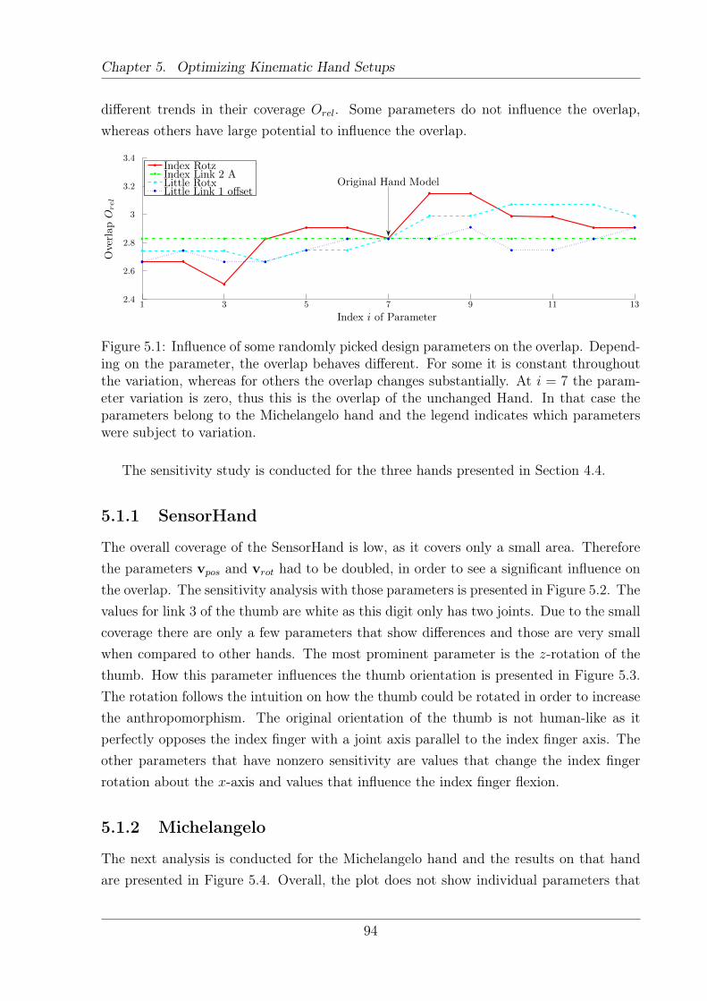
Chapter 5. Optimizing Kinematic Hand Setups
different trends in their coverage Orel. Some parameters do not influence the overlap,whereas others have large potential to influence the overlap.
Index i of Parameter
OverlapO
rel
1 3 5 7 9 11 132.4
2.6
2.8
3
3.2
3.4Index RotzIndex Link 2 ALittle RotxLittle Link 1 offset
Original Hand Model
Figure 5.1: Influence of some randomly picked design parameters on the overlap. Depend-ing on the parameter, the overlap behaves different. For some it is constant throughoutthe variation, whereas for others the overlap changes substantially. At i = 7 the param-eter variation is zero, thus this is the overlap of the unchanged Hand. In that case theparameters belong to the Michelangelo hand and the legend indicates which parameterswere subject to variation.
The sensitivity study is conducted for the three hands presented in Section 4.4.
5.1.1 SensorHand
The overall coverage of the SensorHand is low, as it covers only a small area. Thereforethe parameters vpos and vrot had to be doubled, in order to see a significant influence onthe overlap. The sensitivity analysis with those parameters is presented in Figure 5.2. Thevalues for link 3 of the thumb are white as this digit only has two joints. Due to the smallcoverage there are only a few parameters that show differences and those are very smallwhen compared to other hands. The most prominent parameter is the z-rotation of thethumb. How this parameter influences the thumb orientation is presented in Figure 5.3.The rotation follows the intuition on how the thumb could be rotated in order to increasethe anthropomorphism. The original orientation of the thumb is not human-like as itperfectly opposes the index finger with a joint axis parallel to the index finger axis. Theother parameters that have nonzero sensitivity are values that change the index fingerrotation about the x-axis and values that influence the index finger flexion.
5.1.2 Michelangelo
The next analysis is conducted for the Michelangelo hand and the results on that handare presented in Figure 5.4. Overall, the plot does not show individual parameters that
94
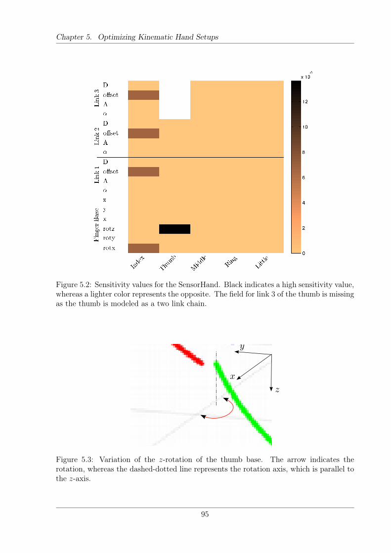
Chapter 5. Optimizing Kinematic Hand Setups
Figure 5.2: Sensitivity values for the SensorHand. Black indicates a high sensitivity value,whereas a lighter color represents the opposite. The field for link 3 of the thumb is missingas the thumb is modeled as a two link chain.
x
y
z
Figure 5.3: Variation of the z-rotation of the thumb base. The arrow indicates therotation, whereas the dashed-dotted line represents the rotation axis, which is parallel tothe z-axis.
95
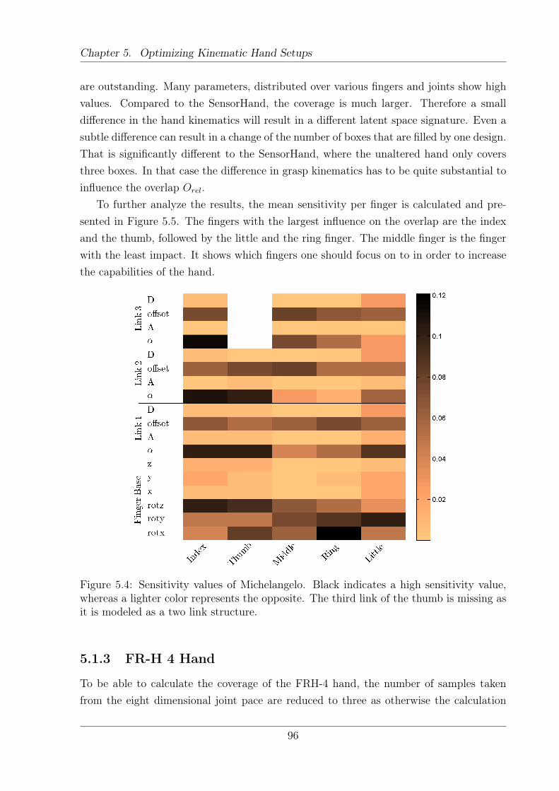
Chapter 5. Optimizing Kinematic Hand Setups
are outstanding. Many parameters, distributed over various fingers and joints show highvalues. Compared to the SensorHand, the coverage is much larger. Therefore a smalldifference in the hand kinematics will result in a different latent space signature. Even asubtle difference can result in a change of the number of boxes that are filled by one design.That is significantly different to the SensorHand, where the unaltered hand only coversthree boxes. In that case the difference in grasp kinematics has to be quite substantial toinfluence the overlap Orel.
To further analyze the results, the mean sensitivity per finger is calculated and pre-sented in Figure 5.5. The fingers with the largest influence on the overlap are the indexand the thumb, followed by the little and the ring finger. The middle finger is the fingerwith the least impact. It shows which fingers one should focus on to in order to increasethe capabilities of the hand.
Figure 5.4: Sensitivity values of Michelangelo. Black indicates a high sensitivity value,whereas a lighter color represents the opposite. The third link of the thumb is missing asit is modeled as a two link structure.
5.1.3 FR-H 4 Hand
To be able to calculate the coverage of the FRH-4 hand, the number of samples takenfrom the eight dimensional joint pace are reduced to three as otherwise the calculation
96
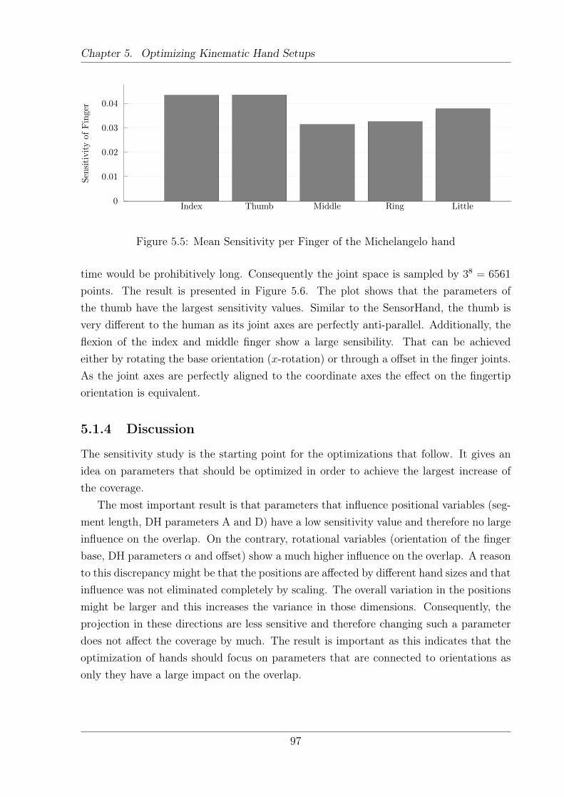
Chapter 5. Optimizing Kinematic Hand Setups
SensitivityofFinger
Index Thumb Middle Ring Little0
0.01
0.02
0.03
0.04
Figure 5.5: Mean Sensitivity per Finger of the Michelangelo hand
time would be prohibitively long. Consequently the joint space is sampled by 38 = 6561
points. The result is presented in Figure 5.6. The plot shows that the parameters ofthe thumb have the largest sensitivity values. Similar to the SensorHand, the thumb isvery different to the human as its joint axes are perfectly anti-parallel. Additionally, theflexion of the index and middle finger show a large sensibility. That can be achievedeither by rotating the base orientation (x-rotation) or through a offset in the finger joints.As the joint axes are perfectly aligned to the coordinate axes the effect on the fingertiporientation is equivalent.
5.1.4 Discussion
The sensitivity study is the starting point for the optimizations that follow. It gives anidea on parameters that should be optimized in order to achieve the largest increase ofthe coverage.
The most important result is that parameters that influence positional variables (seg-ment length, DH parameters A and D) have a low sensitivity value and therefore no largeinfluence on the overlap. On the contrary, rotational variables (orientation of the fingerbase, DH parameters α and offset) show a much higher influence on the overlap. A reasonto this discrepancy might be that the positions are affected by different hand sizes and thatinfluence was not eliminated completely by scaling. The overall variation in the positionsmight be larger and this increases the variance in those dimensions. Consequently, theprojection in these directions are less sensitive and therefore changing such a parameterdoes not affect the coverage by much. The result is important as this indicates that theoptimization of hands should focus on parameters that are connected to orientations asonly they have a large impact on the overlap.
97
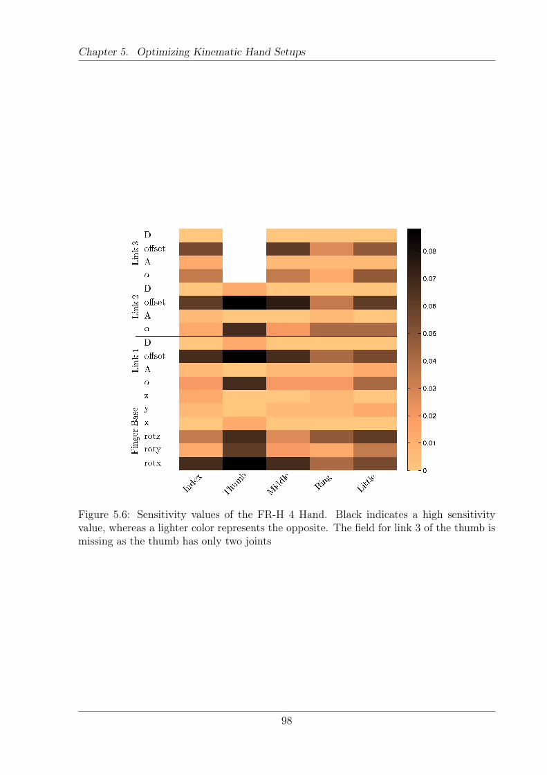
Chapter 5. Optimizing Kinematic Hand Setups
Figure 5.6: Sensitivity values of the FR-H 4 Hand. Black indicates a high sensitivityvalue, whereas a lighter color represents the opposite. The field for link 3 of the thumb ismissing as the thumb has only two joints
98
Chapter 5. Optimizing Kinematic Hand Setups
5.2 Optimization of Kinematic Parameters
Within this section kinematic parameters of hands will be optimized. As it is impossibleto optimize all kinematic parameters of a hand simultaneously, a good initial value forthe optimization is needed. The SensorHand and Michelangelo hand will serve as startingpoint, where various parameters are optimized with respect to the overlap measure. Thefocus is on the Michelangelo hand as it offers the best initial value. The overlap is alreadyhigh, but the hand is still simple as it only has two DoF.
To optimize a given kinematic hand setup, a function fhand : RK → R is created. Theinput parameter is w ∈ RK , where K is the number of parameters to be optimized. Thefunction returns the overlap Orel. In order to calculate Orel, the function creates a handmodel that is based on the models presented in Section 4.4. A variation of the hand iscreated which is governed by the input parameters. The next step is to calculate thefingertip poses and finally to calculate the overlap, which is returned by the function.That can be formulated as
Orel = fhand(w). (5.3)
The function fhand has to be adapted for each optimization, to incorporate the correctmodel and to modify the correct kinematic parameters. Consequently, the parameter setwhich maximizes the coverage Orel is sought.
{wmax} = argmaxwfhand(w) (5.4)
Due to the boxcounting, as described in Section 4.2, method Orel varies non-smoothly.Gradient based optimization techniques cannot be used as they will get stuck on such aplateau. To overcome this problem a probabilistic approach is used – simulated annealing[114] is applied to find an optimal solution. The simulated annealing function provided byMatlab is used. Each optimization is run 10 times in order to determine the distributionof the results. If not terminated earlier by the quality criterion, the optimization wasterminated at 4000 iterations. Test runs have shown that an increase in the number ofiterations does not produce significantly better results. Usually, the algorithm terminatesat the maximal number of iterations.
An overview of all hand models created, analyzed and optimized in this thesis is givenin Figure 5.7. Roughly, the figure reads from top to bottom - the first step is to projectexisting hands and determine their overlap. That is done in the first row. The next stepis to virtually assign more DoF to the hand, as done in the second line. Of particularinterest is the Michelangelo 2D hand, as this determines the mechanical capabilities ofthe hand. The 1D hand is trajectory controlled - various trajectories in the 2D space
99
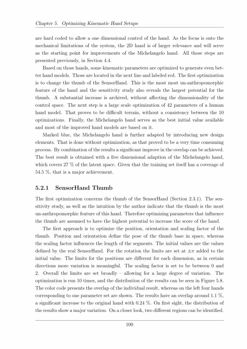
Chapter 5. Optimizing Kinematic Hand Setups
are hard coded to allow a one dimensional control of the hand. As the focus is onto themechanical limitations of the system, the 2D hand is of larger relevance and will serveas the starting point for improvements of the Michelangelo hand. All those steps arepresented previously, in Section 4.4.
Based on those hands, some kinematic parameters are optimized to generate even bet-ter hand models. Those are located in the next line and labeled red. The first optimizationis to change the thumb of the SensorHand. This is the most most un-anthropomorphicfeature of the hand and the sensitivity study also reveals the largest potential for thethumb. A substantial increase is archived, without affecting the dimensionality of thecontrol space. The next step is a large scale optimization of 42 parameters of a humanhand model. That proves to be difficult terrain, without a consistency between the 10optimizations. Finally, the Michelangelo hand serves as the best initial value availableand most of the improved hand models are based on it.
Marked blue, the Michelangelo hand is further adapted by introducing new designelements. That is done without optimization, as that proved to be a very time consumingprocess. By combination of the results a significant improve in the overlap can be achieved.The best result is obtained with a five dimensional adaption of the Michelangelo hand,which covers 27 % of the latent space. Given that the training set itself has a coverage of54.5 %, that is a major achievement.
5.2.1 SensorHand Thumb
The first optimization concerns the thumb of the SensorHand (Section 2.3.1). The sen-sitivity study, as well as the intuition by the author indicate that the thumb is the mostun-anthropomorphic feature of this hand. Therefore optimizing parameters that influencethe thumb are assumed to have the highest potential to increase the score of the hand.
The first approach is to optimize the position, orientation and scaling factor of thethumb. Position and orientation define the pose of the thumb base in space, whereasthe scaling factor influences the length of the segments. The initial values are the valuesdefined by the real SensorHand. For the rotation the limits are set at ±π added to theinitial value. The limits for the positions are different for each dimension, as in certaindirections more variation is meaningful. The scaling factor is set to be between 0 and2. Overall the limits are set broadly – allowing for a large degree of variation. Theoptimization is run 10 times, and the distribution of the results can be seen in Figure 5.8.The color code presents the overlap of the individual result, whereas on the left four handscorresponding to one parameter set are shown. The results have an overlap around 1.1 %,a significant increase to the original hand with 0.24 %. On first sight, the distribution ofthe results show a major variation. On a closer look, two different regions can be identified.
100
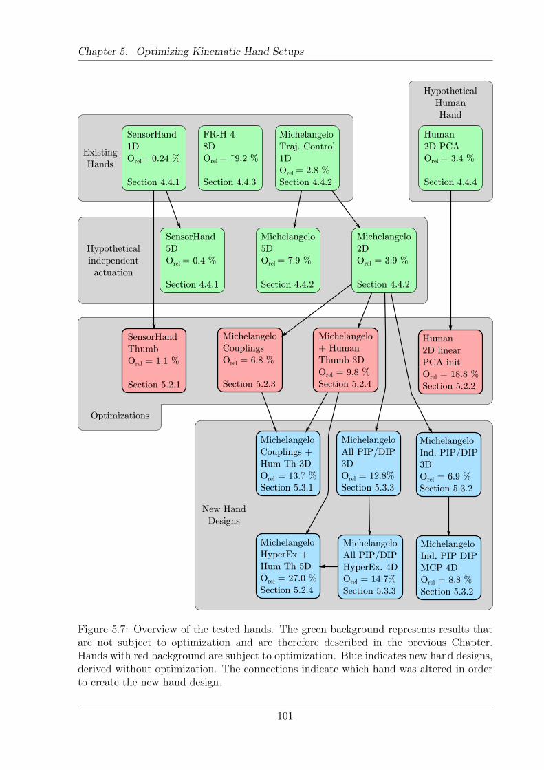
Chapter 5. Optimizing Kinematic Hand Setups
Hypothetical
Human
Hand
Human
2D PCA
Orel = 3.4 %
Section 4.4.4
Human
2D linear
PCA init
Orel = 18.8 %
Section 5.2.2
SensorHand
Thumb
Orel = 1.1 %
Section 5.2.1
Michelangelo
Couplings
Orel = 6.8 %
Section 5.2.3
Michelangelo
+ Human
Thumb 3D
Orel = 9.8 %
Section 5.2.4
Michelangelo
Couplings +
Hum Th 3D
Orel = 13.7 %
Section 5.3.1
Michelangelo
All PIP/DIP
3D
Orel = 12.8%
Section 5.3.3
Michelangelo
Ind. PIP/DIP
3D
Orel = 6.9 %
Section 5.3.2
Michelangelo
Ind. PIP DIP
MCP 4D
Orel = 8.8 %
Section 5.3.2
Michelangelo
All PIP/DIP
HyperEx. 4D
Orel = 14.7%
Section 5.3.3
Michelangelo
HyperEx +
Hum Th 5D
Orel = 27.0 %
Section 5.2.4
SensorHand
1D
Orel= 0.24 %
Section 4.4.1
FR-H 4
8D
Orel = ~9.2 %
Section 4.4.3
Existing
Hands
Michelangelo
Traj. Control
1D
Orel = 2.8 %
Section 4.4.2
Optimizations
Michelangelo
2D
Orel = 3.9 %
Section 4.4.2
Michelangelo
5D
Orel = 7.9 %
Section 4.4.2
Hypothetical
independent
actuation
SensorHand
5D
Orel = 0.4 %
Section 4.4.1
New Hand
Designs
Figure 5.7: Overview of the tested hands. The green background represents results thatare not subject to optimization and are therefore described in the previous Chapter.Hands with red background are subject to optimization. Blue indicates new hand designs,derived without optimization. The connections indicate which hand was altered in orderto create the new hand design.
101
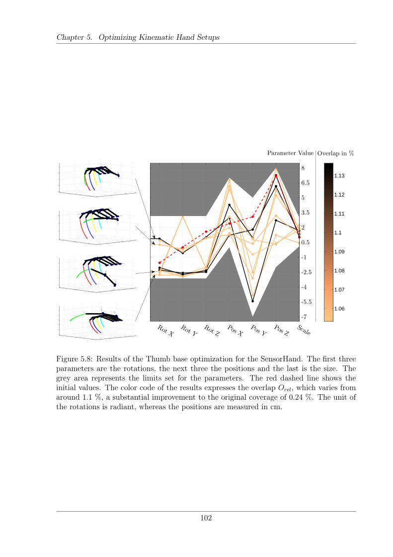
Chapter 5. Optimizing Kinematic Hand Setups
Rot XRot Y
Rot ZPos X
Pos YPos Z
Scale
-7
-5.5
-4
-2.5
-1
0.5
2
3.5
5
6.5
8
1.06
1.07
1.08
1.09
1.1
1.11
1.12
1.13
Parameter Value Overlap in %
Figure 5.8: Results of the Thumb base optimization for the SensorHand. The first threeparameters are the rotations, the next three the positions and the last is the size. Thegrey area represents the limits set for the parameters. The red dashed line shows theinitial values. The color code of the results expresses the overlap Orel, which varies fromaround 1.1 %, a substantial improvement to the original coverage of 0.24 %. The unit ofthe rotations is radiant, whereas the positions are measured in cm.
102
Chapter 5. Optimizing Kinematic Hand Setups
The results of the rotations are quite consistent, basically falling into two parameter sets.Only one result does not fall into one of those. In contrast, the positions and the scalingvary to a large degree. The results are distributed over the complete range, not beingrestricted to certain parameter combinations.
Due to the problems reported in the first optimization run, a second optimizationis conducted. The optimization is restricted to the three rotational parameters. Thelimits are the same as previously and the optimization is run 10 times. The result of thisoptimization is presented in Figure 5.9. Similar to the previous run, two parameter setsare possible. One is about {36,0,40}°and the other is ca. {-144,-144,-144}°. Those arealso the same results as reported in the first optimization run. Again, the images on theleft show four hands that correspond to four parameter sets. The top hand correspondsto the “upper” solution, whereas the three hands below correspond to the “lower” solution.Even though the parameters are very different, the orientation of the thumb looks similar.That is possible as the description with three rotational angles is not unique. To furtherassess the difference between the solutions, the angle between two such orientations iscalculated. Similar to Section 4.3.5 the difference between two quaternions is calculatedvia the dot product. The results reveal that the orientations are consistent within asmall range. The maximal angular difference between two solutions is 21 degrees, withan average difference of about 10 degrees.
The results of the two optimization runs fit well to the sensitivity analysis. It alsosupports the assumption, that in the current implementation the system is only sensibleto orientations. That statement is based on two facts. First, the results of the orientationsare much more consistent when compared to the positions. If the overlap is not influencedby the positions, one can basically pick all parameter values without a penalty from theoverlap. Second, the overlap values are the same in both optimizations. In the two casesthe best overlap is about 1.13 %. If the positions influence Orel, then the first optimizationshould have a larger value.
Overall, the optimization results in a significant improvement to the overlap. Fromthe unchanged SensorHand with 0.24 %, the optimization was able to raise the level upto about 1.1 %. That is an improvement of more than four times without affecting thedimensionality of the hand!
5.2.2 Linear Human Hand Model
The previous result on the SensorHand shows that in a simple case, where only a fewparameters are optimized, the optimization works as intended. It delivers meaningful andconsistent results. Therefore the next step is to go full scale and optimize many parameterssimultaneously. The directional goal is to optimize most kinematic parameters of a hand
103
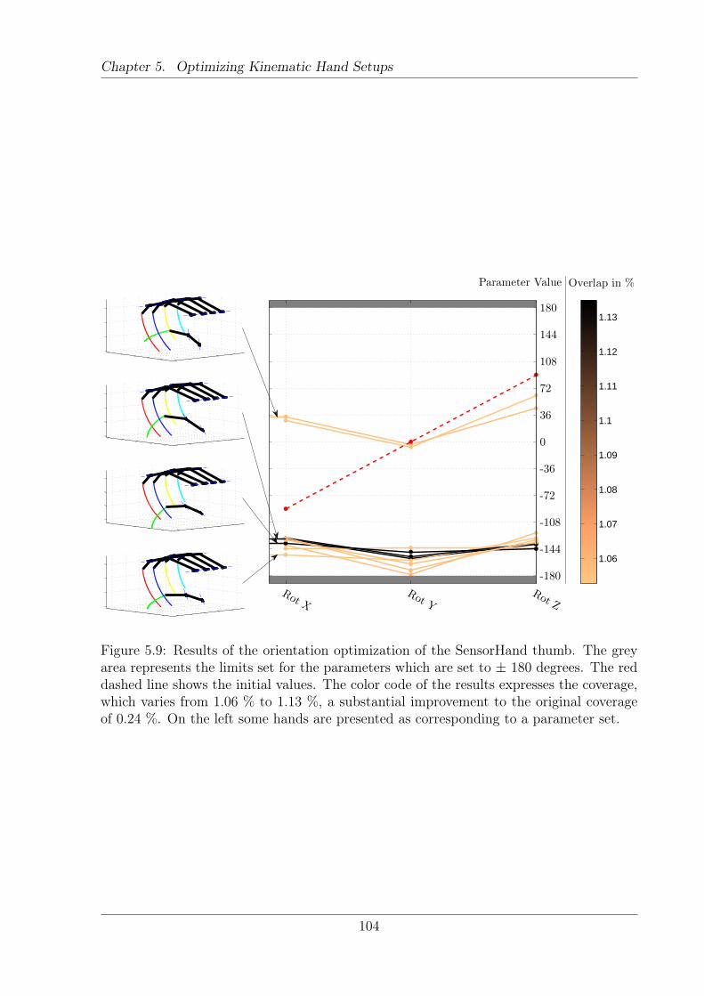
Chapter 5. Optimizing Kinematic Hand Setups
Rot XRot Y
Rot Z
-180
-144
-108
-72
-36
0
36
72
108
144
180
1.06
1.07
1.08
1.09
1.1
1.11
1.12
1.13
Parameter Value Overlap in %
Figure 5.9: Results of the orientation optimization of the SensorHand thumb. The greyarea represents the limits set for the parameters which are set to ± 180 degrees. The reddashed line shows the initial values. The color code of the results expresses the coverage,which varies from 1.06 % to 1.13 %, a substantial improvement to the original coverageof 0.24 %. On the left some hands are presented as corresponding to a parameter set.
104
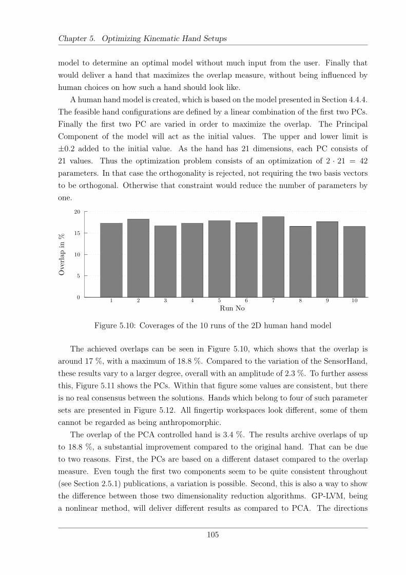
Chapter 5. Optimizing Kinematic Hand Setups
model to determine an optimal model without much input from the user. Finally thatwould deliver a hand that maximizes the overlap measure, without being influenced byhuman choices on how such a hand should look like.
A human hand model is created, which is based on the model presented in Section 4.4.4.The feasible hand configurations are defined by a linear combination of the first two PCs.Finally the first two PC are varied in order to maximize the overlap. The PrincipalComponent of the model will act as the initial values. The upper and lower limit is±0.2 added to the initial value. As the hand has 21 dimensions, each PC consists of21 values. Thus the optimization problem consists of an optimization of 2 · 21 = 42
parameters. In that case the orthogonality is rejected, not requiring the two basis vectorsto be orthogonal. Otherwise that constraint would reduce the number of parameters byone.
Run No
Overlapin
%
1 2 3 4 5 6 7 8 9 100
5
10
15
20
Figure 5.10: Coverages of the 10 runs of the 2D human hand model
The achieved overlaps can be seen in Figure 5.10, which shows that the overlap isaround 17 %, with a maximum of 18.8 %. Compared to the variation of the SensorHand,these results vary to a larger degree, overall with an amplitude of 2.3 %. To further assessthis, Figure 5.11 shows the PCs. Within that figure some values are consistent, but thereis no real consensus between the solutions. Hands which belong to four of such parametersets are presented in Figure 5.12. All fingertip workspaces look different, some of themcannot be regarded as being anthropomorphic.
The overlap of the PCA controlled hand is 3.4 %. The results archive overlaps of upto 18.8 %, a substantial improvement compared to the original hand. That can be dueto two reasons. First, the PCs are based on a different dataset compared to the overlapmeasure. Even tough the first two components seem to be quite consistent throughout(see Section 2.5.1) publications, a variation is possible. Second, this is also a way to showthe difference between those two dimensionality reduction algorithms. GP-LVM, beinga nonlinear method, will deliver different results as compared to PCA. The directions
105
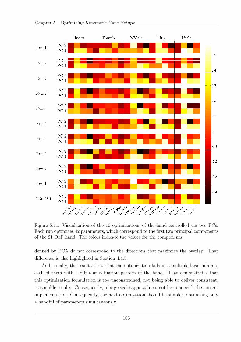
Chapter 5. Optimizing Kinematic Hand Setups
Figure 5.11: Visualization of the 10 optimizations of the hand controlled via two PCs.Each run optimizes 42 parameters, which correspond to the first two principal componentsof the 21 DoF hand. The colors indicate the values for the components.
defined by PCA do not correspond to the directions that maximize the overlap. Thatdifference is also highlighted in Section 4.4.5.
Additionally, the results show that the optimization falls into multiple local minima,each of them with a different actuation pattern of the hand. That demonstrates thatthis optimization formulation is too unconstrained, not being able to deliver consistent,reasonable results. Consequently, a large scale approach cannot be done with the currentimplementation. Consequently, the next optimization should be simpler, optimizing onlya handful of parameters simultaneously.
106
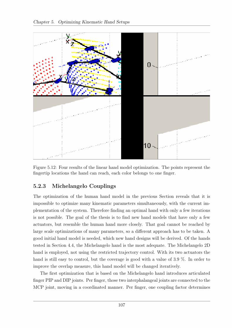
Chapter 5. Optimizing Kinematic Hand Setups
Figure 5.12: Four results of the linear hand model optimization. The points represent thefingertip locations the hand can reach, each color belongs to one finger.
5.2.3 Michelangelo Couplings
The optimization of the human hand model in the previous Section reveals that it isimpossible to optimize many kinematic parameters simultaneously, with the current im-plementation of the system. Therefore finding an optimal hand with only a few iterationsis not possible. The goal of the thesis is to find new hand models that have only a fewactuators, but resemble the human hand more closely. That goal cannot be reached bylarge scale optimizations of many parameters, so a different approach has to be taken. Agood initial hand model is needed, which new hand designs will be derived. Of the handstested in Section 4.4, the Michelangelo hand is the most adequate. The Michelangelo 2Dhand is employed, not using the restricted trajectory control. With its two actuators thehand is still easy to control, but the coverage is good with a value of 3.9 %. In order toimprove the overlap measure, this hand model will be changed iteratively.
The first optimization that is based on the Michelangelo hand introduces articulatedfinger PIP and DIP joints. Per finger, those two interphalangeal joints are connected to theMCP joint, moving in a coordinated manner. Per finger, one coupling factor determines
107
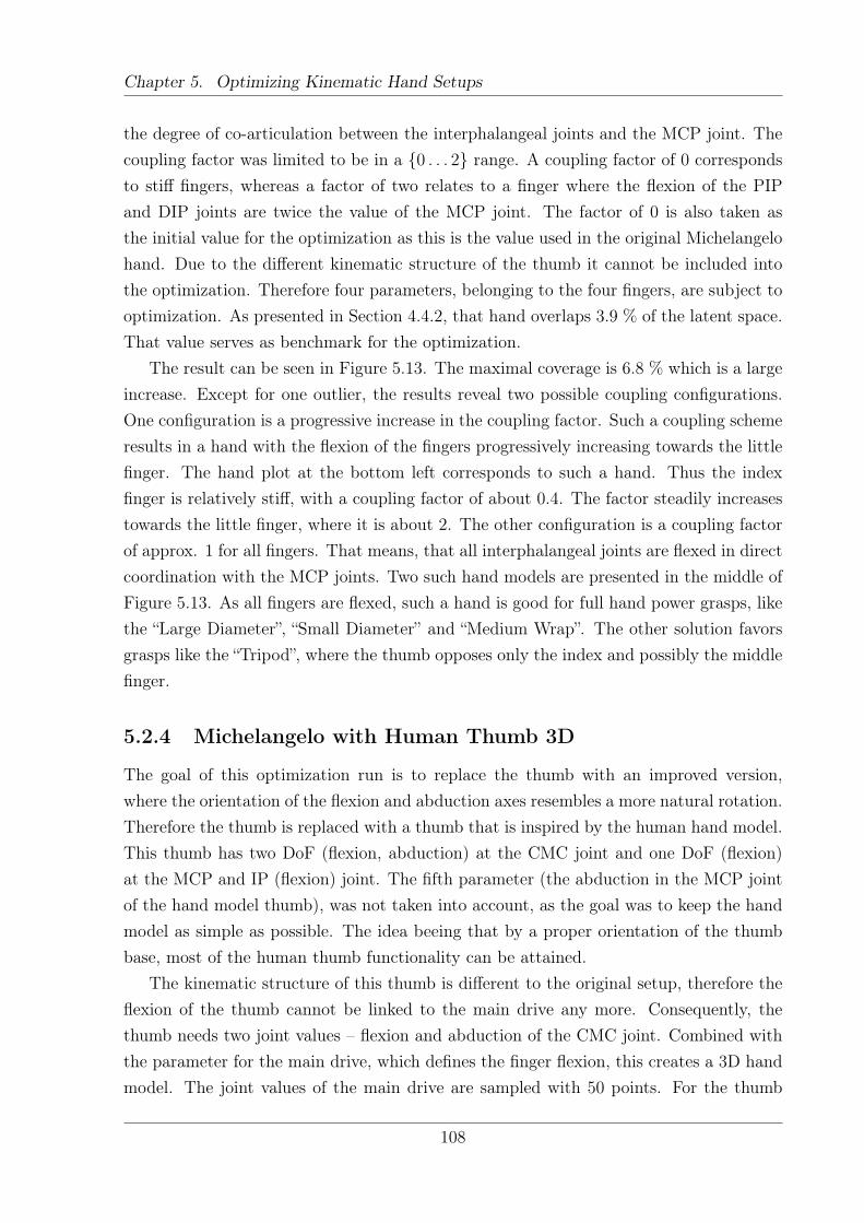
Chapter 5. Optimizing Kinematic Hand Setups
the degree of co-articulation between the interphalangeal joints and the MCP joint. Thecoupling factor was limited to be in a {0 . . . 2} range. A coupling factor of 0 correspondsto stiff fingers, whereas a factor of two relates to a finger where the flexion of the PIPand DIP joints are twice the value of the MCP joint. The factor of 0 is also taken asthe initial value for the optimization as this is the value used in the original Michelangelohand. Due to the different kinematic structure of the thumb it cannot be included intothe optimization. Therefore four parameters, belonging to the four fingers, are subject tooptimization. As presented in Section 4.4.2, that hand overlaps 3.9 % of the latent space.That value serves as benchmark for the optimization.
The result can be seen in Figure 5.13. The maximal coverage is 6.8 % which is a largeincrease. Except for one outlier, the results reveal two possible coupling configurations.One configuration is a progressive increase in the coupling factor. Such a coupling schemeresults in a hand with the flexion of the fingers progressively increasing towards the littlefinger. The hand plot at the bottom left corresponds to such a hand. Thus the indexfinger is relatively stiff, with a coupling factor of about 0.4. The factor steadily increasestowards the little finger, where it is about 2. The other configuration is a coupling factorof approx. 1 for all fingers. That means, that all interphalangeal joints are flexed in directcoordination with the MCP joints. Two such hand models are presented in the middle ofFigure 5.13. As all fingers are flexed, such a hand is good for full hand power grasps, likethe “Large Diameter”, “Small Diameter” and “Medium Wrap”. The other solution favorsgrasps like the “Tripod”, where the thumb opposes only the index and possibly the middlefinger.
5.2.4 Michelangelo with Human Thumb 3D
The goal of this optimization run is to replace the thumb with an improved version,where the orientation of the flexion and abduction axes resembles a more natural rotation.Therefore the thumb is replaced with a thumb that is inspired by the human hand model.This thumb has two DoF (flexion, abduction) at the CMC joint and one DoF (flexion)at the MCP and IP (flexion) joint. The fifth parameter (the abduction in the MCP jointof the hand model thumb), was not taken into account, as the goal was to keep the handmodel as simple as possible. The idea beeing that by a proper orientation of the thumbbase, most of the human thumb functionality can be attained.
The kinematic structure of this thumb is different to the original setup, therefore theflexion of the thumb cannot be linked to the main drive any more. Consequently, thethumb needs two joint values – flexion and abduction of the CMC joint. Combined withthe parameter for the main drive, which defines the finger flexion, this creates a 3D handmodel. The joint values of the main drive are sampled with 50 points. For the thumb
108
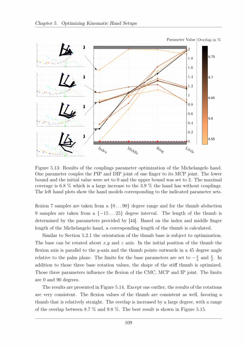
Chapter 5. Optimizing Kinematic Hand Setups
IndexMiddle
RingLittle
0
0.2
0.4
0.6
0.8
1
1.2
1.4
1.6
1.8
2
6.55
6.6
6.65
6.7
6.75
Parameter Value Overlap in %
Figure 5.13: Results of the couplings parameter optimization of the Michelangelo hand.One parameter couples the PIP and DIP joint of one finger to its MCP joint. The lowerbound and the initial value were set to 0 and the upper bound was set to 2. The maximalcoverage is 6.8 % which is a large increase to the 3.9 % the hand has without couplings.The left hand plots show the hand models corresponding to the indicated parameter sets.
flexion 7 samples are taken from a {0 . . . 90} degree range and for the thumb abduction9 samples are taken from a {−15 . . . 25} degree interval. The length of the thumb isdetermined by the parameters provided by [44]. Based on the index and middle fingerlength of the Michelangelo hand, a corresponding length of the thumb is calculated.
Similar to Section 5.2.1 the orientation of the thumb base is subject to optimization.The base can be rotated about x,y and z axis. In the initial position of the thumb theflexion axis is parallel to the y-axis and the thumb points outwards in a 45 degree anglerelative to the palm plane. The limits for the base parameters are set to −π
2and π
2. In
addition to those three base rotation values, the shape of the stiff thumb is optimized.Those three parameters influence the flexion of the CMC, MCP and IP joint. The limitsare 0 and 90 degrees.
The results are presented in Figure 5.14. Except one outlier, the results of the rotationsare very consistent. The flexion values of the thumb are consistent as well, favoring athumb that is relatively straight. The overlap is increased by a large degree, with a rangeof the overlap between 8.7 % and 9.8 %. The best result is shown in Figure 5.15.
109
Chapter 5. Optimizing Kinematic Hand Setups
The plots of the hands show a stunning behavior. Interestingly, the thumb is orientatedvery much outwards. In Figure 5.15(a) the thumb points to the right. At the presentedposition, the thumb is in maximal extension. That is unnaturally extended and thethumb even points above the x-y plane, which corresponds to the palm of the hand. Inmaximal flexion, which is indicated by the green points that correspond to the thumbfingertip locations, the thumb still is not touching the other fingers. The intuition is thatin maximal flexion the trajectories of thumb and fingers should intersect. Why such athumb orientation is selected cannot be determined. One explanation might be that inmost grasps an object is held between the fingers and the thumb. Therefore there is adistance between those fingertips, which is also the case for this hand model.
On the contrary, the orientation of the CMC joint axes look very natural and cor-respond to the human intuition. They are similar to the position determined in theSensorHand thumb optimization in Figure 5.9. The angular difference between the bestresult of each optimization is 21 degrees. Given that the hand models are different andthe optimization includes also other parameters, the difference is small. It seems thatthere is one optimal value for the orientation of the thumb CMC flexion axis.
5.3 Validation of Design Elements
The previous section presented how kinematic parameters of hand models can be opti-mized. The optimizations proved to be difficult and time consuming, therefore an alterna-tive approach is taken in this Section. New design elements and DoF will be introduced,and their influence on the coverage is determined. This does not deliver the best possibleparameter set, but determines the quality of the conceived design.
5.3.1 Michelangelo Couplings with Human Thumb 3D
In the Sections 5.2.3 and 5.2.4 two different parts of the Michelangelo hand were modifiedto increase the latent space overlap. The first optimization couples the PIP and DIPjoints to the MCP joints. That adaption increases the latent space coverage from 3.9 %(the 2 dimensional Michelangelo) to 6.8 %. The second optimization replaces the thumb.A more human-like thumb is added, where the base rotation of the thumb and the zeroflexion is subject to optimization. In that case the coverage increases from 3.9 % to 9.9 %.As both results optimized different parts of the hand, the results were composed creatinga new hand model. The best results from both cases are taken, conferring a 3D handmodel. The main drive flexes the fingers and two actuators control the thumb of the hand.Figure 5.16 shows the projection of the fingertip movements to the latent space. The resultis that the hand is able to overlap 13.9 %, a large increase to the individual optimization
110
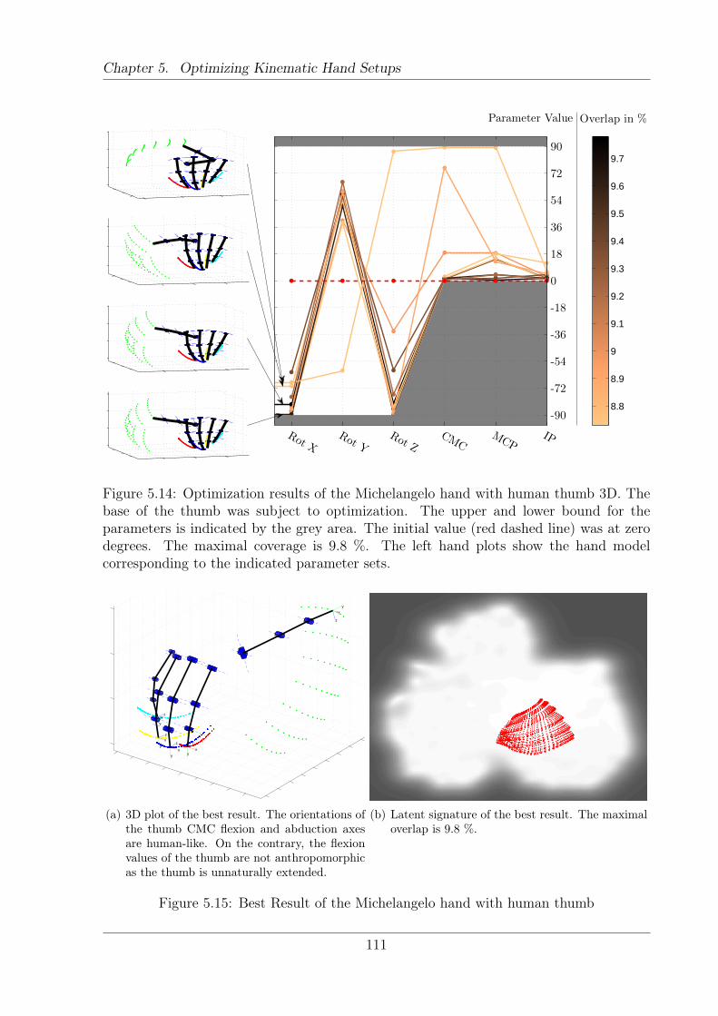
Chapter 5. Optimizing Kinematic Hand Setups
Rot XRot Y
Rot ZCMC
MCPIP
-90
-72
-54
-36
-18
0
18
36
54
72
90
8.8
8.9
9
9.1
9.2
9.3
9.4
9.5
9.6
9.7
Parameter Value Overlap in %
Figure 5.14: Optimization results of the Michelangelo hand with human thumb 3D. Thebase of the thumb was subject to optimization. The upper and lower bound for theparameters is indicated by the grey area. The initial value (red dashed line) was at zerodegrees. The maximal coverage is 9.8 %. The left hand plots show the hand modelcorresponding to the indicated parameter sets.
xy
z
x
y
z
x
y
zx
y
z
x
y
z
(a) 3D plot of the best result. The orientations ofthe thumb CMC flexion and abduction axesare human-like. On the contrary, the flexionvalues of the thumb are not anthropomorphicas the thumb is unnaturally extended.
(b) Latent signature of the best result. The maximaloverlap is 9.8 %.
Figure 5.15: Best Result of the Michelangelo hand with human thumb
111
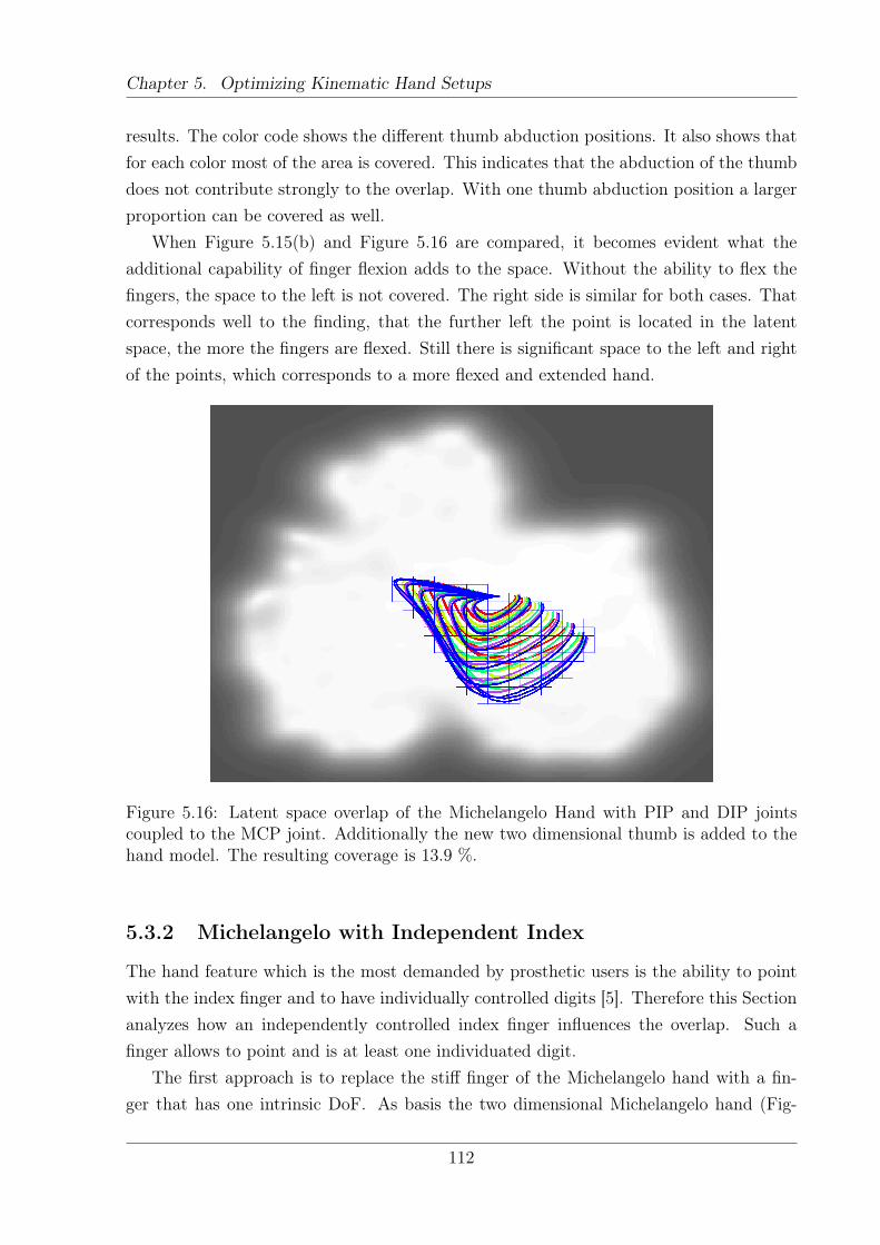
Chapter 5. Optimizing Kinematic Hand Setups
results. The color code shows the different thumb abduction positions. It also shows thatfor each color most of the area is covered. This indicates that the abduction of the thumbdoes not contribute strongly to the overlap. With one thumb abduction position a largerproportion can be covered as well.
When Figure 5.15(b) and Figure 5.16 are compared, it becomes evident what theadditional capability of finger flexion adds to the space. Without the ability to flex thefingers, the space to the left is not covered. The right side is similar for both cases. Thatcorresponds well to the finding, that the further left the point is located in the latentspace, the more the fingers are flexed. Still there is significant space to the left and rightof the points, which corresponds to a more flexed and extended hand.
Figure 5.16: Latent space overlap of the Michelangelo Hand with PIP and DIP jointscoupled to the MCP joint. Additionally the new two dimensional thumb is added to thehand model. The resulting coverage is 13.9 %.
5.3.2 Michelangelo with Independent Index
The hand feature which is the most demanded by prosthetic users is the ability to pointwith the index finger and to have individually controlled digits [5]. Therefore this Sectionanalyzes how an independently controlled index finger influences the overlap. Such afinger allows to point and is at least one individuated digit.
The first approach is to replace the stiff finger of the Michelangelo hand with a fin-ger that has one intrinsic DoF. As basis the two dimensional Michelangelo hand (Fig-
112
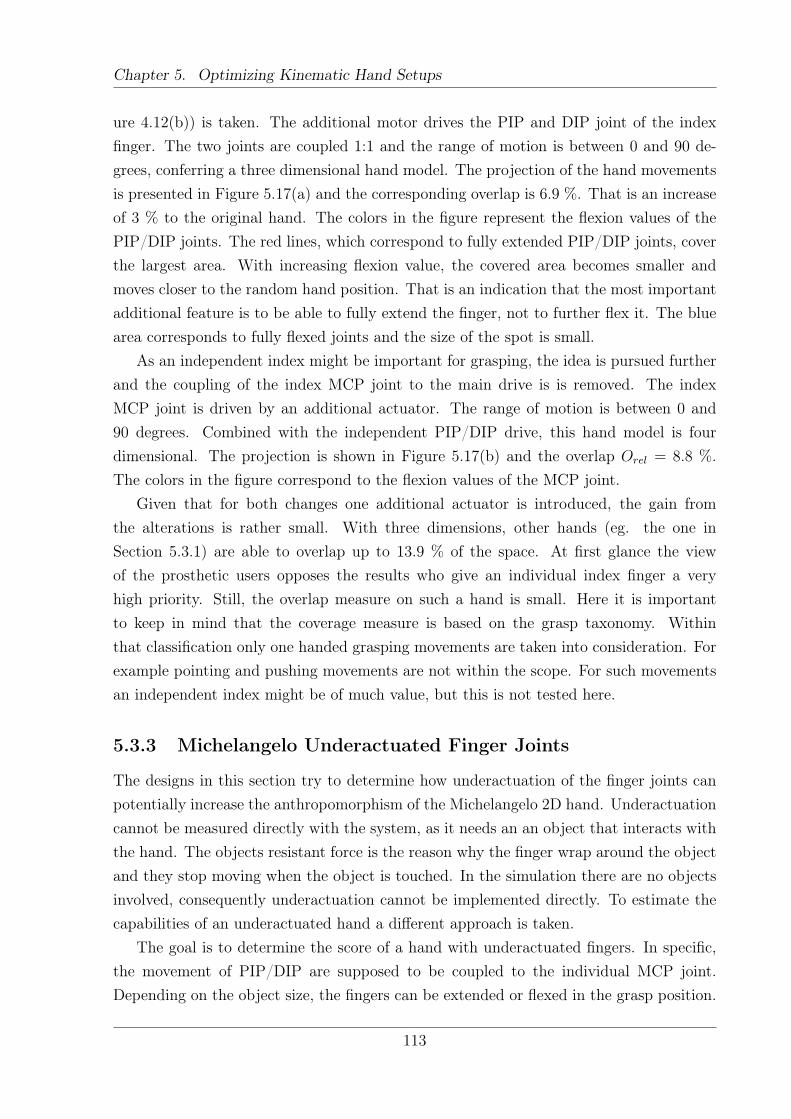
Chapter 5. Optimizing Kinematic Hand Setups
ure 4.12(b)) is taken. The additional motor drives the PIP and DIP joint of the indexfinger. The two joints are coupled 1:1 and the range of motion is between 0 and 90 de-grees, conferring a three dimensional hand model. The projection of the hand movementsis presented in Figure 5.17(a) and the corresponding overlap is 6.9 %. That is an increaseof 3 % to the original hand. The colors in the figure represent the flexion values of thePIP/DIP joints. The red lines, which correspond to fully extended PIP/DIP joints, coverthe largest area. With increasing flexion value, the covered area becomes smaller andmoves closer to the random hand position. That is an indication that the most importantadditional feature is to be able to fully extend the finger, not to further flex it. The bluearea corresponds to fully flexed joints and the size of the spot is small.
As an independent index might be important for grasping, the idea is pursued furtherand the coupling of the index MCP joint to the main drive is is removed. The indexMCP joint is driven by an additional actuator. The range of motion is between 0 and90 degrees. Combined with the independent PIP/DIP drive, this hand model is fourdimensional. The projection is shown in Figure 5.17(b) and the overlap Orel = 8.8 %.The colors in the figure correspond to the flexion values of the MCP joint.
Given that for both changes one additional actuator is introduced, the gain fromthe alterations is rather small. With three dimensions, other hands (eg. the one inSection 5.3.1) are able to overlap up to 13.9 % of the space. At first glance the viewof the prosthetic users opposes the results who give an individual index finger a veryhigh priority. Still, the overlap measure on such a hand is small. Here it is importantto keep in mind that the coverage measure is based on the grasp taxonomy. Withinthat classification only one handed grasping movements are taken into consideration. Forexample pointing and pushing movements are not within the scope. For such movementsan independent index might be of much value, but this is not tested here.
5.3.3 Michelangelo Underactuated Finger Joints
The designs in this section try to determine how underactuation of the finger joints canpotentially increase the anthropomorphism of the Michelangelo 2D hand. Underactuationcannot be measured directly with the system, as it needs an an object that interacts withthe hand. The objects resistant force is the reason why the finger wrap around the objectand they stop moving when the object is touched. In the simulation there are no objectsinvolved, consequently underactuation cannot be implemented directly. To estimate thecapabilities of an underactuated hand a different approach is taken.
The goal is to determine the score of a hand with underactuated fingers. In specific,the movement of PIP/DIP are supposed to be coupled to the individual MCP joint.Depending on the object size, the fingers can be extended or flexed in the grasp position.
113
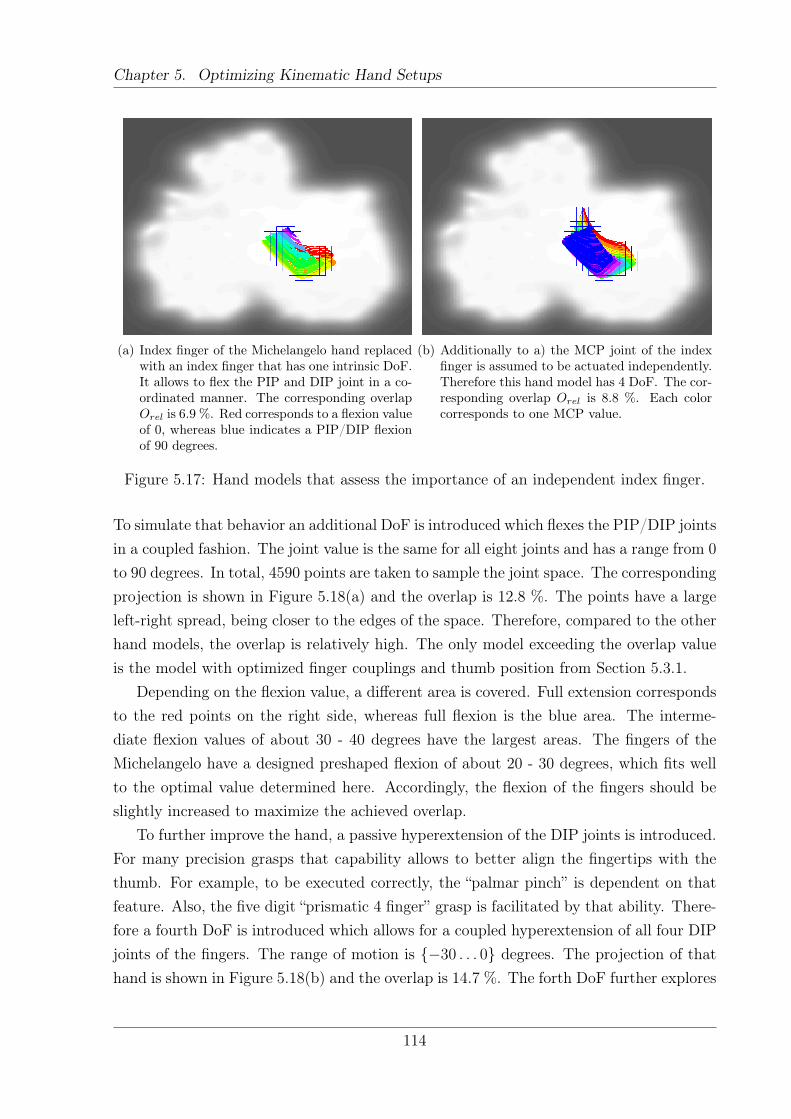
Chapter 5. Optimizing Kinematic Hand Setups
(a) Index finger of the Michelangelo hand replacedwith an index finger that has one intrinsic DoF.It allows to flex the PIP and DIP joint in a co-ordinated manner. The corresponding overlapOrel is 6.9 %. Red corresponds to a flexion valueof 0, whereas blue indicates a PIP/DIP flexionof 90 degrees.
(b) Additionally to a) the MCP joint of the indexfinger is assumed to be actuated independently.Therefore this hand model has 4 DoF. The cor-responding overlap Orel is 8.8 %. Each colorcorresponds to one MCP value.
Figure 5.17: Hand models that assess the importance of an independent index finger.
To simulate that behavior an additional DoF is introduced which flexes the PIP/DIP jointsin a coupled fashion. The joint value is the same for all eight joints and has a range from 0to 90 degrees. In total, 4590 points are taken to sample the joint space. The correspondingprojection is shown in Figure 5.18(a) and the overlap is 12.8 %. The points have a largeleft-right spread, being closer to the edges of the space. Therefore, compared to the otherhand models, the overlap is relatively high. The only model exceeding the overlap valueis the model with optimized finger couplings and thumb position from Section 5.3.1.
Depending on the flexion value, a different area is covered. Full extension correspondsto the red points on the right side, whereas full flexion is the blue area. The interme-diate flexion values of about 30 - 40 degrees have the largest areas. The fingers of theMichelangelo have a designed preshaped flexion of about 20 - 30 degrees, which fits wellto the optimal value determined here. Accordingly, the flexion of the fingers should beslightly increased to maximize the achieved overlap.
To further improve the hand, a passive hyperextension of the DIP joints is introduced.For many precision grasps that capability allows to better align the fingertips with thethumb. For example, to be executed correctly, the “palmar pinch” is dependent on thatfeature. Also, the five digit “prismatic 4 finger” grasp is facilitated by that ability. There-fore a fourth DoF is introduced which allows for a coupled hyperextension of all four DIPjoints of the fingers. The range of motion is {−30 . . . 0} degrees. The projection of thathand is shown in Figure 5.18(b) and the overlap is 14.7 %. The forth DoF further explores
114
Chapter 5. Optimizing Kinematic Hand Setups
the latent space by 1.9 %. Again, the color code represents the new feature - in that casethe hyperextension of the DIP joints. For each hyperextension value, the points basicallycover the same space as previously. That explains why the increase in the coverage issmall. It seems that this feature is of minor importance for the grasping capabilities.
Both results give a rough estimation of the real capabilities of the underactuated hand.At this stage it is not possible to determine if the real hand shapes would be simpler ormore complex than the model. If it was simpler, meaning that the PIP and DIP jointsare coupled directly to the MCP values, that hand model would be similar to the one inSection 5.3.1. In that case the underactuated hand overlap is reduced, being closer to6.8 %. On the other hand, if the hand has to conform itself to many different object sizesand shapes, the hand shapes could be more complex. In particular the coupling betweenfingers would be broken, conferring the hand model higher complexity. If that is the casethe overlap would even exceed 14.7 %.
The latent space signatures in in Figure 5.18 show, that in both cases there is a trajec-tory moving to the random hand position. Starting from the left top of the point cloud,it moves horizontally to the right until it reaches the random hand location. In Fig-ure 5.18(a), most of the blue points correspond to that trajectory. That point representsthe random hand model, therefore postures that fall onto that spot are non anthropomor-phic. To determine which flexion angles contribute to the coverage, the maximal flexionvalue for both models is both varied and the overlap is calculated. Figure 5.19 shows thedependency of the maximal flexion value for both hand models. At around 80 degrees thecurves flatten out. That means that adding a larger flexion capability to the hand doesnot add extra functionality to the hand. It only increases the complexity of the hand, asa larger range of motion adds extra mechanical challenges. According to this plot it issufficient to flex the fingers up to a maximum of ca. 80 degrees.
5.3.4 Michelangelo with Human Thumb and Underactuation
This hand combines the best results that have been achieved in the previous Sections. Ittakes the best result from the optimization which is the changed thumb with an overlapof 9.8 %. Additionally the best hand so far from this Section, which is the hand withunderactuation abilities, is taken. This hand has a common flexion of the PIP and DIPjoints and the hyperextension of the DIP joint which results in an overlap of 14.7 %.Those two results are combined to a new hand with a total of five DoF. Those are:
1. Combined flexion of all four finger MCP joints according to the main drive coupling
2. Combined flexion of all four finger PIP/DIP joints up to 90 degrees
3. Hyperextension of the finger DIP joints up to 30 degrees
115
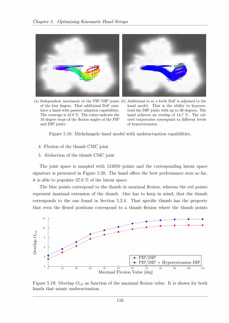
Chapter 5. Optimizing Kinematic Hand Setups
(a) Independent movement of the PIP/DIP jointsof the four fingers. That additional DoF emu-lates a hand with passive adaption capabilities.The coverage is 12.8 %. The colors indicate the10 degree steps of the flexion angles of the PIPand DIP joints.
(b) Additional to a) a forth DoF is adjoined to thehand model. That is the ability to hyperex-tend the DIP joints with up to 30 degrees. Thehand achieves an overlap of 14.7 %. The col-ored trajectories correspond to different levelsof hyperextension.
Figure 5.18: Michelangelo hand model with underactuation capabilities.
4. Flexion of the thumb CMC joint
5. Abduction of the thumb CMC joint
The joint space is sampled with 124950 points and the corresponding latent spacesignature is presented in Figure 5.20. The hand offers the best performance seen so far,it is able to populate 27.0 % of the latent space.
The blue points correspond to the thumb in maximal flexion, whereas the red pointsrepresent maximal extension of the thumb. One has to keep in mind, that the thumbcorresponds to the one found in Section 5.2.4. That specific thumb has the propertythat even the flexed positions correspond to a thumb flexion where the thumb points
Maximal Flexion Value [deg]
OverlapO
rel
0 10 20 30 40 50 60 70 80 90 100 1100
3
6
9
12
15
PIP/DIPPIP/DIP + Hyperextension DIP
Figure 5.19: Overlap Orel as function of the maximal flexion value. It is shown for bothhands that mimic underactuation.
116
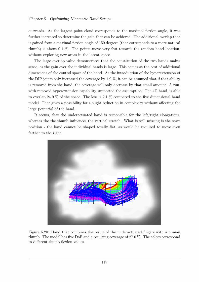
Chapter 5. Optimizing Kinematic Hand Setups
outwards. As the largest point cloud corresponds to the maximal flexion angle, it wasfurther increased to determine the gain that can be achieved. The additional overlap thatis gained from a maximal flexion angle of 150 degrees (that corresponds to a more naturalthumb) is about 0.1 %. The points move very fast towards the random hand location,without exploring new areas in the latent space.
The large overlap value demonstrates that the constitution of the two hands makessense, as the gain over the individual hands is large. This comes at the cost of additionaldimensions of the control space of the hand. As the introduction of the hyperextension ofthe DIP joints only increased the coverage by 1.9 %, it can be assumed that if that abilityis removed from the hand, the coverage will only decrease by that small amount. A run,with removed hyperextension capability supported the assumption. The 4D hand, is ableto overlap 24.9 % of the space. The loss is 2.1 % compared to the five dimensional handmodel. That gives a possibility for a slight reduction in complexity without affecting thelarge potential of the hand.
It seems, that the underactuated hand is responsible for the left/right elongations,whereas the the thumb influences the vertical stretch. What is still missing is the startposition - the hand cannot be shaped totally flat, as would be required to move evenfarther to the right.
Figure 5.20: Hand that combines the result of the underactuated fingers with a humanthumb. The model has five DoF and a resulting coverage of 27.0 %. The colors correspondto different thumb flexion values.
117
Chapter 5. Optimizing Kinematic Hand Setups
5.4 Discussion
The process of optimizing kinematic hand setups proved difficult. First, the parametersthat are subject to optimization have to be defined with care. A poor definition of theparameters ends in local minima and no consistency between different runs of the sameoptimization problem. Similarly, if too many parameters are optimized in parallel, manylocal solutions will be found. That prohibits finding an optimal hand in only a fewiteration steps, given the current implementation. Additionally, such an optimization istime consuming, taking about 24 hours on a computer with Intel® Core™ i7 CPU and 8GB of RAM. Therefore corrections in the optimization problem and iterations over newhands take time. Still, this approach is much faster than the classical approach of buildingprototypes.
During the optimizations the limits for the parameters were set very wide, thus notrestricting the parameters to meaningful regions. The optimized parameters show a be-havior that they follow the intuition of the author and tend not to run into the definedlimits.
As already indicated by the sensitivity study in Section 5.1, the orientations dominatethe optimization and have a sharp maximum. For future applications, the goal shouldbe to shape the system in such a way, that both orientations and positions influence theoverlap. That will increase the overall quality of the results as some properties of thehand model can only be measured by the positions.
The results show, that an additional DoF, that affects all fingers has a larger impacton the coverage compared to movements of single fingers. For example the introduction ofa coupled DoF that flexes the PIP/DIP joints of the fingers resulted in a larger coveragethan an index finger that has an additional DoF. There are two possible explanationsfor this. First, having an additional parameter that moves many fingers, results in achange in many dimensions of the dataspace, thus increasing the action manifold. Alarger volume most likely will result in a larger overlap. Second, the hands are all stillsimple in design. Therefore it might be the case that a variation in the full hand flexionfacilitates more grasps than an independently controlled index finger. In the latter caseonly a few precision grasps are made possible. Up until now no hands have been realized,thus it is not possible to rule out one of these possibilities. It needs extensive testing withreal prototypes to answer this issue.
Some hands show a tendency that their latent points come close to the position of therandom hand. That is the location where all non-anthropomorphic hand configurationscollapse onto. Therefore this location represents a large variety of hand configurations,which do not resemble the human grasping movements. At the moment the system doesnot process this information at all. A more thorough analysis on the points that fall onto
118
Chapter 5. Optimizing Kinematic Hand Setups
that region might hold additional insights on the behavior of the hand. For example, ifhalf of the hand configurations fall onto that spot, it could be argued, that the hand hasmany capabilities that can be removed without affecting the anthropomorphism of thehand. That could lead to a simpler hand design with the same capabilities. It might evenbe of benefit to add a penalty for points that are close to the random hand location, thusactively pushing the points away from that location during the optimization.
Except for the measurement of the human kinematics, there are no objects present inthe simulations. The advantage of that is, that the output is not specific to a certain classof objects. Still, due to the absence of objects, underactuation cannot be implementeddirectly. To work, underactuation needs an object which exerts force onto the digits.A workaround is to introduce additional virtual DoF, that simulate the different fingerpostures that are possible due to wrapping around objects. Such an approach is taken inSection 5.3.3, where underactuated fingers are analyzed.
Concerning the results of the optimizations and the creation of new hand designs,it has been shown that the introduction of more DoF are no guarantee to increase theanthropomorphism of hands. The FR-4 hand, with its 8 actuators covers nearly 10 %of the latent space. Such an overlap value can be even exceeded by a hand with threeactuators. For example the hand described in Section 5.3.3 is able to cover 12.8 %. Asmart coupling of more than one joint to one actuator and a proper orientation of theaxes made such a result possible.
Overall it has been shown that the system works as intended, simplifying and accel-erating the design process of new prosthetic and robotic hands. New hands were createdvirtually and evaluated with respect to the overlap measure. Within half a year, wherethe system has been used to find new hand designs, multiple new hand models could becreated. The theoretical findings still should be validated using a real prototype.
119
Chapter 6Conclusion
Creating new – improved – artificial hands is a difficult process. Commonly, the hand isbased on the ideas of the engineers designing it. Depending on the experience and skillof the engineer, the resulting hand will be of different quality. In order to determine thequality of a design, it needs to be built and tested in real life experiments. Such a processis both expensive and time consuming. This thesis deals with the problem and developsa method to determine the quality of anthropomorphic hands prior to realization.
The first step towards the goal is to define human hand usage. The human hand servesas the golden standard in grasping, being the most versatile hand we know of. Thereforea comprehensive grasp taxonomy is created, based on an extensive literature survey ofexisting grasp classifications. A definition clarifies which grasps are relevant for the study– the focus is on one handed static grasps. The comprehensive taxonomy consists of 33different grasp types, incorporating all relevant grasps from previous studies. Of that set31 grasp types were used to define the human hand capabilities. The perfect artificialhand will be able to perform all those grasps.
The main contribution of the thesis is a system which allows to compare the capa-bilities of a kinematic hand setup with the grasping movements of the human. A largeoverlap of the movements indicates that the hand is anthropomorphic, whereas a smalloverlap indicates the opposite. The presented method is the first approach to quantify theanthropomorphism of prosthetic and robotic hands prior to realization. Therefore thistool has a large potential in speeding up the design process, as a new hand design can beevaluated at an earlier stage. The large advantage of the system lies in the fact, that itallows for a large range of hands to be tested; the only limitation is that the hand has tobe five-fingered. Apart from this, the hand can have arbitrary complexity, with all kindsof coupling definitions. They can be hard coded or be based on nonlinear functions. Thetoolbox Grade Your Own Hand [105] has been made public, which allows the communityto test their hands and compare it against other designs.
120
Chapter 6. Conclusion
The applicability of the system is shown in different ways. First, it is used to determinethe anthropomorphism of two existing prosthetic and one robotic hand. It shows thata large number of actuators does not imply large anthropomorphism. Second, based onthe overlap measure, kinematic parameters were optimized, resulting in hand designs thatare optimal with respect to this measure. The results look good, following the humanintuition on improved versatility. Finally, all prior results are combined, creating newhand designs that yield a large potential dexterity with only a few actuators.
Overall, it was shown that an increase in the degree of anthropomorphism can beachieved by a smart definition of the hand kinematics. It is not a prerequisite for sucha hand that it has many Degrees of Freedom. That can be seen by comparing differenthands with the same number of actuators; for example if the five dimensional SensorHandis compared to the 5D Michelangelo hand. In both cases the same joints are actuated,but due to differences in the kinematic chains of the fingers the overlap is significantlydifferent. The SensorHand, where all joint axes are parallel and the thumb is perfectlyopposing the the fingers, has an overlap of 0.4 %. In contrast, the Michelangelo hand,which features a much more human like orientation of the joints, is able to populate 7.9 %of the space. That demonstrates, that even though the control space is similar, the resultsare significantly different.
Hands, that were created using the system, have not been realized and tested in areal application. Therefore the results presented in the thesis all have a certain degreeof uncertainty. In the future, some hand designs should be actually built and their per-formance compared with the results from the overlap measure. Only then a conclusivestatement concerning the validity of the results can be given.
The presented methodology is not limited to five-fingered general purpose hands. Theunderlying human dataset defines the movement against which the artificial hands arecontrasted. Therefore exchanging that dataset exchanges the paradigm of a perfect hand.For example, if precision grasps are the main focus, a new dataset could be createdconsisting of a range of precision grasps.
6.1 Outlook
There are various things that can be done in order to continue with the research.The results are only as good as the input. In that case that is the Comprehensive
Grasp Taxonomy, which defines what movement the artificial designs are supposed tomimic. The classification is based on a literature survey, yet it is not based on observinghumans in everyday life situations. Therefore the possibility exists that some grasp typeswere never taken into consideration, whereas others could be neglected.
121
Chapter 6. Conclusion
To overcome the limitations, a completely different approach is necessary. One wouldhave to use a data driven approach, where many subjects are recorded performing all kindsof different hand movements. To record the hand postures the instrumentation should beas non-invasive as possible, thus reducing the influence on the results. Another importantconstraint is that the dataset should represent all hand movements, not being restrictedto a special application. Such a dataset can be the basis for a variety of analysis. Oneapproach would be to perform a cluster analysis to determine the hand postures whichrepresent the majority of movements. That grasp list would consist of snapshots of handconfigurations without taking time into account. A more elaborate approach would beto extract not only a snap shot, but model the grasp as a parametric model. Such agrasp type would be a function of the object size. Therefore the problems introducedby different object sizes could be removed. In the comprehensive grasp taxonomy thatproblem is present, as some grasps differ only by the object size. Such grasp types couldbe merged to one model.
The presented overlap measure is the first step to access the degree of similaritybetween human and robot hand. Yet, there is some potential for improvement. At themoment the system processes snapshots of hand configurations without taking time anddynamics into account. Not only the hand configurations should be human-like, but alsothe movements of an artificial hand should resemble the human. Therefore it is desirablethat the trajectories of human and machine are parallel in the latent space. Such atrajectory should be given a higher score, as compared to a perpendicular trajectory.More work is needed in order to implement such measures to the system as well.
Finally, it should be investigated if the general approach can be extended to otherareas where two high dimensional entities have to be compared. One possible applicationmight be to compare full body movements of human and robot. The same principlescan be applied in that case, where a large overlap indicates that the robotic kinematicstructure is similar to the human. That can be used to gain similar insights on the overalllevel of anthropomorphism of an robot, similar to the results obtained on hands in thisthesis.
122
Glossary
ACT Anatomically Correct TestbedBC Back Constraint: A extension to GP-LVM which allows a fast
projection from data to latent space [85].CMC Carpo-MetacarpalCT Computed TomographyDIP Distal InterphalangealDH Denavit Hartenberg: A formalism to describe a kinematic chain
[41].DoF Degree of Freedom: Minimal number of parameters necessary to
specify the configuration of a system.DR Dimensionality Reduction: The process of projecting data to a
lower dimensional embedding which maintains most of thestructure of the space.
GP-LVM Gaussian Process Latent Variable Model: A probabilisticnonlinear dimensionality reduction algorithm, first proposed by[86].
Intrinsic Movement The object is being manipulated without a global movement ofthe arm.
IP InterphalangealLLE Locally Linear Embedding: A local, nonlinear dimensionality
reduction algorithm [76,78].MCP MetacarpalMDS Multi Dimensional Scaling: A global, nonlinear dimensionality
reduction algorithm [76].PC Principal Component: One basis vector as determined by PCA.PCA Principal Component Analysis: A linear dimensionality reduction
algorithm [67].
123
Chapter 6. Conclusion
PIP Proximal InterphalangealPose Position and Orientation combined to one vector.Posture Configuration of the hand.RBF Radial Basis Function : A type of kernel for GP-LVMVF Virtual Finger: One or more fingers work together as one function
unit, the virtual finger.
124
List of Figures
2.1 The human forearm anatomy . . . . . . . . . . . . . . . . . . . . . . . . . 52.2 Bones of the human hand . . . . . . . . . . . . . . . . . . . . . . . . . . . 62.3 Range of motion of the Metacarpal joint . . . . . . . . . . . . . . . . . . . 72.4 Differences of the grasp stability when the thumb is employed . . . . . . . 82.5 Opposition types . . . . . . . . . . . . . . . . . . . . . . . . . . . . . . . . 102.6 Sequence of hand grasps . . . . . . . . . . . . . . . . . . . . . . . . . . . . 112.7 Prosthetic hands by Otto Bock . . . . . . . . . . . . . . . . . . . . . . . . 132.8 Touch Bionics I-Limb™ ultra hand . . . . . . . . . . . . . . . . . . . . . . 142.9 The Shadow Dexterous Hand C6 . . . . . . . . . . . . . . . . . . . . . . . 142.10 FRH-4 Hand . . . . . . . . . . . . . . . . . . . . . . . . . . . . . . . . . . 152.11 Denavit Hartenberg coordinate frame definition . . . . . . . . . . . . . . . 202.12 Comparison of the first two Principal Components . . . . . . . . . . . . . . 26
3.1 Taxonomy of Schlesinger . . . . . . . . . . . . . . . . . . . . . . . . . . . . 333.2 Grasp types listed by Coones and Chao . . . . . . . . . . . . . . . . . . . . 333.3 The “Power Grip” category from Kamakura et al. . . . . . . . . . . . . . . 353.4 The “Intermediate Grip” category from Kamakura et al. . . . . . . . . . . . 363.5 The “Precision Grip” category from Kamakura et al. . . . . . . . . . . . . . 373.6 Kamakura’s “Grip involving no thumb” . . . . . . . . . . . . . . . . . . . . 383.7 Eight basic hand positions according to Lister . . . . . . . . . . . . . . . . 383.8 Elliott and Conolly’s hand postures . . . . . . . . . . . . . . . . . . . . . . 393.9 Grasps named by Lyons [94] . . . . . . . . . . . . . . . . . . . . . . . . . . 403.10 Grasp types defined by Kroemer . . . . . . . . . . . . . . . . . . . . . . . . 413.11 Grasp types referenced by Cutkosky . . . . . . . . . . . . . . . . . . . . . . 423.12 Grasp Types as defined by Kang and Ikeuchi . . . . . . . . . . . . . . . . . 433.13 Six hand postures by Light et al. . . . . . . . . . . . . . . . . . . . . . . . 443.14 Grasp types defined by Exner . . . . . . . . . . . . . . . . . . . . . . . . . 45
125
List of Figures
3.15 Power grasps as defined by Edwards et al. . . . . . . . . . . . . . . . . . . 463.16 Combination of Power and Precision grasps as defined by Edwards et al. . 473.17 Precision grasps as defined by Edwards et al. . . . . . . . . . . . . . . . . . 473.18 Miscellaneous and Nonprehensile grasps according to Edwards et al. . . . . 483.19 Kapandji’s grasp types . . . . . . . . . . . . . . . . . . . . . . . . . . . . . 49
4.1 Overview over the system to quantify the hand anthropomorphism . . . . . 594.2 Hypothetical visualization of the fingertip space . . . . . . . . . . . . . . . 604.3 Setup of the fingertip sensors. . . . . . . . . . . . . . . . . . . . . . . . . . 654.4 Setup of the experiments. . . . . . . . . . . . . . . . . . . . . . . . . . . . 664.5 Human Grasping Dataset . . . . . . . . . . . . . . . . . . . . . . . . . . . 674.6 Kernel width explanation . . . . . . . . . . . . . . . . . . . . . . . . . . . . 704.7 GMM/GMR processing pipeline. . . . . . . . . . . . . . . . . . . . . . . . 734.8 Two random hand models. . . . . . . . . . . . . . . . . . . . . . . . . . . . 744.9 Grasp trajectories in the latent space. . . . . . . . . . . . . . . . . . . . . . 774.10 Projections to determine the latent space quality. . . . . . . . . . . . . . . 784.11 Projection of the Otto Bock SensorHand . . . . . . . . . . . . . . . . . . . 804.12 Different Michelangelo Models and their overlap of the latent space . . . . 834.13 Projection of the FRH-4 hand . . . . . . . . . . . . . . . . . . . . . . . . . 844.14 The human hand model controlled via two PCs and its projection . . . . . 864.15 System description to restrict the training set to a linear subspace . . . . . 864.16 Projection of PCA spaces . . . . . . . . . . . . . . . . . . . . . . . . . . . 884.17 Comparison of PCA results over the dimension . . . . . . . . . . . . . . . . 89
5.1 Influence of parameters on the overlap . . . . . . . . . . . . . . . . . . . . 945.2 Sensitivity values for the SensorHand . . . . . . . . . . . . . . . . . . . . . 955.3 Variation of the z-rotation of the thumb . . . . . . . . . . . . . . . . . . . 955.4 Sensitivity values of Michelangelo . . . . . . . . . . . . . . . . . . . . . . . 965.5 Mean Sensitivity per Finger of the Michelangelo hand . . . . . . . . . . . . 975.6 Sensitivity values of the FR-H 4 Hand . . . . . . . . . . . . . . . . . . . . 985.7 Overview of the tested hands . . . . . . . . . . . . . . . . . . . . . . . . . 1015.8 Results of the Thumb base optimization for the SensorHand. . . . . . . . . 1025.9 Results of the orientation optimization of the SensorHand thumb . . . . . 1045.10 Coverages of the 10 runs of the 2D human hand model . . . . . . . . . . . 1055.11 Visualization of the 10 optimizations of the 2D human hand . . . . . . . . 1065.12 Four results of the linear hand model optimization . . . . . . . . . . . . . . 1075.13 Results of the couplings parameter optimization of the Michelangelo hand . 1095.14 Optimization results of the Michelangelo hand with human thumb 3D . . . 111
126
List of Figures
5.15 Best Result of the Michelangelo hand with human thumb . . . . . . . . . . 1115.16 Overlap of the Michelangelo Hand with PIP and DIP joints coupled to the
MCP joint . . . . . . . . . . . . . . . . . . . . . . . . . . . . . . . . . . . . 1125.17 Hand models that assess the importance of an independent index finger . . 1145.18 Michelangelo hand model with underactuation capabilities . . . . . . . . . 1165.19 Overlap Orel as function of the maximal flexion value . . . . . . . . . . . . 1165.20 Hand that combines the result of the underactuated fingers with a human
thumb . . . . . . . . . . . . . . . . . . . . . . . . . . . . . . . . . . . . . . 117
127
List of Tables
2.1 Comparison of human hand models . . . . . . . . . . . . . . . . . . . . . . 22
3.1 Kapandji’s grasp type classification . . . . . . . . . . . . . . . . . . . . . . 503.2 Taxonomy comparison sheet . . . . . . . . . . . . . . . . . . . . . . . . . . 523.3 Grasp list . . . . . . . . . . . . . . . . . . . . . . . . . . . . . . . . . . . . 543.4 Comprehensive Grasp Taxonomy . . . . . . . . . . . . . . . . . . . . . . . 55
4.1 Scores of the latent space models . . . . . . . . . . . . . . . . . . . . . . . 76
128
Bibliography
[1] L. Biagiotti, F. Lotti, C. Melchiorri, and G. Vassura, “How far is the human hand?a review on anthropomorphic end effectors,” DIES Internal Report, University ofBologna, Tech. Rep., 2004.
[2] P. Parker, K. Englehart, and B. Hudgins, “Myoelectric signal processing for controlof powered limb prostheses.” Journal of electromyography and kinesiology, vol. 16,no. 6, pp. 541–548, Dec. 2006.
[3] W. Craelius, “The bionic man: Restoring mobility,” Science, vol. 295, no. 5557, pp.1018–1021, Feb. 2002.
[4] P. J. Kyberd, C. Wartenberg, L. Sandsjö, S. Jönsson, D. Gow, J. Frid, C. Almström,and L. Sperling, “Survey of upper extremity prosthesis users in sweden and theunited kingdom,” JPO: Journal of Prosthetics and Orthotics, vol. 19, no. 2, p. 55,2007.
[5] C. Pylatiuk, S. Schulz, and L. Döderlein, “Results of an internet survey of myoelec-tric prosthetic hand users.” Prosthetics and orthotics international, vol. 31, no. 4,pp. 362–370, Dec. 2007.
[6] E. N. Marieb and K. Hoehn, Human Anatomy And Physiology, 7th ed. Benjamin-Cummings Publishing Company, May 2006.
[7] J. M. Landsmeer, “The coordination of finger-joint motions.” The Journal of boneand joint surgery. American volume, vol. 45, pp. 1654–1662, December 1963.
[8] H. Gray, Anatomy of the human body. Philadelphia: Lea & Febiger, 1918,bartleby.com, 2000. [Online]. Available: http://www.bartleby.com/107/
129
Bibliography
[9] I. A. Kapandji, Funktionelle Anatomie der Gelenke. Schematisierte und kommen-tierte Zeichnungen zur menschlichen Biomechanik. Thieme Georg Verlag, January2006.
[10] Wikipedia, “Hand — wikipedia, the free encyclopedia,” 2011, [accessed 15-September-2011]. [Online]. Available: http://en.wikipedia.org/w/index.php?title=Hand&oldid=450496853
[11] C. E. Lang and M. H. Schieber, “Human finger independence: limitations due topassive mechanical coupling versus active neuromuscular control.” Journal of neu-rophysiology, vol. 92, no. 5, pp. 2802–2810, November 2004.
[12] C. H. Ross and M. H. Schieber, “Quantifying the independence of human fingermovements: Comparisons of digits, hands, and movement frequencies,” The Journalof neuroscience : the official journal of the Society for Neuroscience, vol. 20, no. 22,pp. 8542–8550, November 2000.
[13] J. Ingram, K. Körding, I. Howard, and D. Wolpert, “The statistics of natural handmovements,” Experimental Brain Research, vol. 188, no. 2, pp. 223–236, June 2008.
[14] D. J. Giurintano, A. M. Hollister, W. L. Buford, D. E. Thompson, and L. M. Myers,“A virtual five-link model of the thumb.” Medical Engineering and Physics, vol. 17,no. 4, pp. 297–303, June 1995.
[15] J. R. Napier, “The prehensile movements of the human hand.” The Journal of boneand joint surgery. British volume, vol. 38-B, no. 4, pp. 902–913, November 1956.
[16] T. Iberall, G. Bingham, and M. A. Arbib, “Opposition space as a structuring conceptfor the analysis of skilled hand movements,” Experimental Brain Research Series,vol. 15, pp. 158–173, 1986.
[17] T. Iberall, “Human prehension and dexterous robot hands,” The International Jour-nal of Robotics Research, vol. 16, no. 3, pp. 285–299, June 1997.
[18] C. L. Mackenzie and T. Iberall, The Grasping Hand, Volume 104 (Advances inPsychology), 1st ed. North Holland, Feb. 1994.
[19] J. M. Landsmeer, “Power grip and precision handling.” Annals of the rheumaticdiseases, vol. 21, pp. 164–170, June 1962.
[20] N. Kamakura, M. Matsuo, H. Ishii, F. Mitsuboshi, and Y. Miura, “Patterns ofstatic prehension in normal hands.” The American journal of occupational therapy.
130
Bibliography
: official publication of the American Occupational Therapy Association, vol. 34,no. 7, pp. 437–445, July 1980.
[21] T. Iberall, “The nature of human prehension: Three dextrous hands in one,” inRobotics and Automation. Proceedings. 1987 IEEE International Conference on,vol. 4, 1987, pp. 396–401.
[22] P. J. Kyberd, A. Clawson, and B. Jones, “The use of underactuation in prostheticgrasping,” Mechanical Sciences, vol. 2, no. 1, pp. 27–32, 2011.
[23] Otto Bock. SensorHand Speed. [accessed 15-September-2011]. [Online]. Available:http://www.ottobock.com/cps/rde/xchg/ob_com_en/hs.xsl/3652.html
[24] A. Muzumdar, Powered Upper Limb Prostheses: Control, Implementation and Clin-ical Application, 1st ed. Springer, Feb. 2004.
[25] M. C. Carrozza, G. Cappiello, S. Micera, B. B. Edin, L. Beccai, and C. Cipriani,“Design of a cybernetic hand for perception and action,” Biological Cybernetics,vol. 95, no. 6, pp. 629–644, Dec. 2006.
[26] Otto Bock. (2011) Otto Bock at the trade fair 2010 Leipzig. [accessed15-September-2011]. [Online]. Available: http://leipzig.ottobock.de/index.php?id=161&no_cache=1&L=1
[27] Touch Bionics. Myoelectric Control. [accessed 28-September-2011]. [Online].Available: http://www.touchbionics.com/media/2210/i-limb%20ultra%20data%20sheet%20lo-res.pdf
[28] ——. i-Limb ultra. [accessed 28-September-2011]. [Online]. Available: http://www.touchbionics.com/products/active-prostheses/i-limb-ultra/
[29] Shadow Robot Company. (accessed 15-September-2011) Shadow Hand range.[Online]. Available: http://www.shadowrobot.com/downloads/shadow_dextrous_hand_technical_specification_C6M.pdf
[30] ——. (accessed 28-September-2011, Aug.) Shadow Hand range. [Online]. Available:http://www.shadowrobot.com/hand/techspec.shtml
[31] I. Gaiser, S. Schulz, A. Kargov, H. Klosek, A. Bierbaum, C. Pylatiuk, R. Oberle,T. Werner, T. Asfour, G. Bretthauer, and R. Dillmann, “A new anthropomorphicrobotic hand,” Dec. 2008, pp. 418–422.
131
Bibliography
[32] A. Bicci, “Revisiting grasping basics,” in Robotics, Science and Systems Conference:Workshop Grasp Acquisition: How to Realize Good Grasps, Jun. 2010.
[33] M. Mason, S. Srinivasa, and A. Vazquez, “Generality and simple hands,” RoboticsResearch, pp. 345–361, 2011.
[34] A. Bicchi, “Hands for dexterous manipulation and robust grasping: a difficult roadtoward simplicity,” Robotics and Automation, IEEE Transactions on, vol. 16, no. 6,pp. 652–662, 2000.
[35] M. T. Ciocarlie and P. K. Allen, “Hand posture subspaces for dexterous roboticgrasping,” Int. J. Rob. Res., vol. 28, no. 7, pp. 851–867, July 2009.
[36] M. Ciocarlie and P. Allen, “Data-driven optimization for underactuated robotichands,” in 2010 IEEE International Conference on Robotics and Automation (ICRA2010). IEEE, May 2010, pp. 1292–1299.
[37] D. Pratichizzo, M. Malvezzi, and A. Bicchi, “On motion and force controllabilityof grasping hands with postural synergies,” in Proceedings of Robotics: Science andSystems, Zaragoza, Spain, June 2010.
[38] M. Malhotra and Y. Matsuoka, “The relationship between actuator reduction andcontrollability for a robotic hand,” pp. 331–336, 2010.
[39] M. J. Farrugia and M. A. Saliba, “Optimisation of anthropomorphic robot handdesign through human manual dexterity testing,” VDI BERICHTE, vol. 1956, p.147, 2006.
[40] R. S. Hartenberg and J. Denavit, Kinematic Synthesis of Linkages (MechanicalEngineering Series), first edition ed. McGraw-Hill Inc.,US, 1964.
[41] J. Denavit and R. S. Hartenberg, “A kinematic notation for lower-pair mechanismsbased on matrices.” Trans. of the ASME. Journal of Applied Mechanics, vol. 22, pp.215–221, 1955.
[42] M. W. Spong and M. Vidyasagar, Robot Dynamics and Control. Wiley, January1989.
[43] K. N. An, E. Y. Chao, W. P. Cooney, and R. L. Linscheid, “Normative model ofhuman hand for biomechanical analysis.” Journal of biomechanics, vol. 12, no. 10,pp. 775–788, 1979.
132
Bibliography
[44] B. Buchholz, T. J. Armstrong, and S. A. Goldstein, “Anthropometric data for de-scribing the kinematics of the human hand.” Ergonomics, vol. 35, no. 3, pp. 261–273,March 1992.
[45] B. Buchholz and T. J. Armstrong, “A kinematic model of the human hand to evalu-ate its prehensile capabilities.” Journal of biomechanics, vol. 25, no. 2, pp. 149–162,February 1992.
[46] J. L. Sancho Bru, A. P. González, M. Vergara, and D. J. Giurintano, “A 3d biome-chanical model of the hand for power grip.” Journal of biomechanical engineering,vol. 125, no. 1, pp. 78–83, February 2003.
[47] S. W. Lee and X. Zhang, “Development and evaluation of an optimization-basedmodel for power-grip posture prediction.” Journal of biomechanics, vol. 38, no. 8,pp. 1591–1597, August 2005.
[48] H. Rijpkema and M. Girard, “Computer animation of knowledge-based humangrasping,” SIGGRAPH Comput. Graph., vol. 25, no. 4, pp. 339–348, 1991.
[49] Y. Yasumuro, “Three-dimensional modeling of the human hand with motion con-straints,” Image and Vision Computing, vol. 17, no. 2, pp. 149–156, February 1999.
[50] I. Albrecht, J. Haber, and H. P. Seidel, “Construction and animation of anatomi-cally based human hand models,” in SCA ’03: Proceedings of the 2003 ACM SIG-GRAPH/Eurographics symposium on Computer animation. Aire-la-Ville, Switzer-land, Switzerland: Eurographics Association, 2003, pp. 98–109.
[51] H. Wan, Y. Luo, S. Gao, and Q. Peng, “Realistic virtual hand modeling with ap-plications for virtual grasping,” in VRCAI ’04: Proceedings of the 2004 ACM SIG-GRAPH international conference on Virtual Reality continuum and its applicationsin industry. New York, NY, USA: ACM, 2004, pp. 81–87.
[52] T. Kurihara and N. Miyata, “Modeling deformable human hands from medical im-ages,” in SCA ’04: Proceedings of the 2004 ACM SIGGRAPH/Eurographics sympo-sium on Computer animation. Aire-la-Ville, Switzerland, Switzerland: Eurograph-ics Association, 2004, pp. 355–363.
[53] E. P. Pitarch, J. Yang, and K. A. Malek, “Santos hand: A 25-Degree-of-Freedommodel,” in Proceedings of SAE Digital Human Modeling for Design and Engineering,Iowa City, Iowa, USA, 2005.
133
Bibliography
[54] S. Cobos, M. Ferre, M. A. Sanchez Uran, J. Ortego, and C. Pena, “Efficient humanhand kinematics for manipulation tasks,” in Intelligent Robots and Systems, 2008.IROS 2008. IEEE/RSJ International Conference on, 2008, pp. 2246–2251.
[55] O. A. van Nierop, A. van der Helm, K. J. Overbeeke, and T. J. Djajadiningrat,“A natural human hand model,” The Visual Computer, vol. 24, no. 1, pp. 31–44,January 2008.
[56] J. Lee and T. L. Kunii, “Model-based analysis of hand posture,” IEEE Comput.Graph. Appl., vol. 15, no. 5, pp. 77–86, 1995.
[57] J. Lin, Y. Wu, and T. S. Huang, “Modeling the constraints of human hand motion,”in Human Motion, 2000. Proceedings. Workshop on, 2000, pp. 121–126.
[58] M. Veber and T. Bajd, “Assessment of human hand kinematics,” in Robotics andAutomation, 2006. ICRA 2006. Proceedings 2006 IEEE International Conferenceon, 2006, pp. 2966–2971.
[59] J. R. et al., “Hands in action, real-time 3d reconstruction of hands in interactionwith objects,” in ICRA 09:00-09:15, Paper TuA12.3, 2010.
[60] N. Rezzoug and P. Gorce, “Prediction of fingers posture using artificial neural net-works,” Journal of Biomechanics, vol. 41, no. 12, pp. 2743–2749, August 2008.
[61] J. Choi, “Developing a 3-dimensional kinematic model of the hand for ergonomicanalyses of hand posture, hand space envelope, and tendon excursion,” Ph.D. dis-sertation, The University of Michigan, 2008.
[62] C. Goldfeder, M. Ciocarlie, H. Dang, and P. K. Allen, “The columbia graspdatabase,” in 2009 IEEE International Conference on Robotics and Automation,May 2009.
[63] M. Ciocarlie, C. Goldfeder, and P. Allen, “Dimensionality reduction for hand-independent dexterous robotic grasping,” in Intelligent Robots and Systems, 2007.IROS 2007. IEEE/RSJ International Conference on, 2007, pp. 3270–3275.
[64] X. Zhang, S. W. Lee, and P. Braido, “Determining finger segmental centers of rota-tion in flexion-extension based on surface marker measurement.” J Biomech, vol. 36,no. 8, pp. 1097–1102, August 2003.
[65] L. A. Jones and S. J. Lederman, Human Hand Function, 1st ed. Oxford UniversityPress, USA, April 2006.
134
Bibliography
[66] J. Romero, T. Feix, C.-H. Ek, H. Kjellström, and D. Kragic, “Extracting posturalsynergies for grasping,” Robotics and Automation, IEEE Transactions on, submit-ted.
[67] I. T. Jolliffe, Principal Component Analysis, 2nd ed. Springer, October 2002.
[68] M. Santello, M. Flanders, and J. F. Soechting, “Postural hand synergies for tooluse,” J. Neurosci., vol. 18, no. 23, pp. 10 105–10 115, December 1998.
[69] A. Cordero, O. Levin, Y. Li, and S. P. Swinnen, “Principal component analysis ofcomplex multijoint coordinative movements.” Biological cybernetics, vol. 93, no. 1,pp. 63–78, July 2005.
[70] E. Todorov and Z. Ghahramani, “Analysis of the synergies underlying complex handmanipulation,” in 26th Annual International Conference of the IEEE Engineeringin Medicine and Biology Society, vol. 4. IEEE, 2004, pp. 4637–4640.
[71] P. Braido and X. Zhang, “Quantitative analysis of finger motion coordination inhand manipulative and gestic acts.” Human movement science, vol. 22, no. 6, pp.661–678, April 2004.
[72] H. Abdi and L. J. Williams, “Principal components analysis,” Wiley InterdisciplinaryReviews: Computational Statistics, vol. 2, 2010.
[73] C. M. Bishop, Pattern Recognition and Machine Learning (Information Science andStatistics), 1st ed. Springer, October 2007.
[74] J. B. Tenenbaum, V. Silva, and J. C. Langford, “A global geometric frameworkfor nonlinear dimensionality reduction,” Science, vol. 290, no. 5500, pp. 2319–2323,December 2000.
[75] P. H. Thakur, A. J. Bastian, and S. S. Hsiao, “Multidigit movement synergies ofthe human hand in an unconstrained haptic exploration task.” The Journal of neu-roscience : the official journal of the Society for Neuroscience, vol. 28, no. 6, pp.1271–1281, February 2008.
[76] L. J. P. van der Maaten, E. O. Postma, and H. J. van den Herik, “Dimensionalityreduction: A comparative review,” MICC, Maastricht University, P.O. Box 616,6200 MD Maastricht, Netherlands, Tech. Rep., February 2008.
[77] A. Tsoli and O. C. Jenkins, “Neighborhood denoising for learning high-dimensionalgrasping manifolds,” in 2008 IEEE/RSJ International Conference on IntelligentRobots and Systems (IROS 2008). IEEE, Sep. 2008, pp. 3680–3685.
135
Bibliography
[78] S. T. Roweis and L. K. Saul, “Nonlinear dimensionality reduction by locally linearembedding,” Science, vol. 290, no. 5500, pp. 2323–2326, December 2000.
[79] C. H. Ek, P. H. S. Torr, and N. D. Lawrence, Gaussian Process Latent Variable Mod-els for Human Pose Estimation. Berlin, Heidelberg: Springer Berlin Heidelberg,2008, vol. 4892, ch. 12, pp. 132–143.
[80] S. Hou, A. Galata, F. Caillette, N. Thacker, and P. Bromiley, “Real-time bodytracking using a gaussian process latent variable model,” Computer Vision, IEEEInternational Conference on, vol. 0, pp. 1–8, 2007.
[81] R. Urtasun, D. J. Fleet, and P. Fua, “3D people tracking with gaussian processdynamical models,” in CVPR ’06: Proceedings of the 2006 IEEE Computer SocietyConference on Computer Vision and Pattern Recognition. Washington, DC, USA:IEEE Computer Society, 2006, pp. 238–245.
[82] J. M. Wang, D. J. Fleet, and A. Hertzmann, “Gaussian process dynamical models forhuman motion,” IEEE Transactions on Pattern Analysis and Machine Intelligence,vol. 30, no. 2, pp. 283–298, Feb. 2008.
[83] R. Urtasun, D. J. Fleet, A. Geiger, J. Popović, T. J. Darrell, and N. D. Lawrence,“Topologically-constrained latent variable models,” in ICML ’08: Proceedings of the25th international conference on Machine learning, ser. ACM International Confer-ence Proceeding Series, vol. 307. New York, NY, USA: ACM, 2008, pp. 1080–1087.
[84] N. D. Lawrence, “The gaussian process latent variable model,” The University ofSheffield, Department of Computer Science., Tech. Rep., 2006.
[85] N. D. Lawrence and J. Quiñonero Candela, “Local distance preservation in the GP-LVM through back constraints,” in the 23rd international conference, ser. ICML ’06.New York, New York, USA: ACM Press, 2006, pp. 513–520.
[86] N. Lawrence, “Probabilistic non-linear principal component analysis with gaussianprocess latent variable models,” Journal of Machine Learning Research, vol. 6, pp.1783–1816, 2005.
[87] T. Feix, R. Pawlik, H.-B. Schmiedmayer, J. Romero, and D. Kragic, “Acomprehensive grasp taxonomy,” in Robotics, Science and Systems Conference:Workshop on Understanding the Human Hand for Advancing Robotic Manipulation,Poster Presentation, June 2009. [Online]. Available: http://grasp.xief.net
[88] G. Schlesinger, Der Mechanische Aufbau der Kunstlichen Glieder. Ersatzglieder undArbeitshilfen, part II. Berlin: Springer, 1919.
136
Bibliography
[89] C. L. Taylor and R. J. Schwarz, “The anatomy and mechanics of the human hand.”Artificial limbs, vol. 2, no. 2, pp. 22–35, May 1955.
[90] D. B. Slocum and D. R. Pratt, “Disability evaluation of the hand,” J. Bone JointSurg, vol. 28, pp. 491–495, 1946.
[91] W. P. Cooney and E. Y. Chao, “Biomechanical analysis of static forces in the thumbduring hand function,” J Bone Joint Surg Am, vol. 59, no. 1, pp. 27–36, January1977.
[92] G. Lister, The hand: Diagnosis and surgical indications. Churchill Livingstone,1984.
[93] J. M. Elliott and K. J. Connolly, “A classification of manipulative hand movements.”Developmental medicine and child neurology, vol. 26, no. 3, pp. 283–296, June 1984.
[94] D. Lyons, “A simple set of grasps for a dextrous hand,” in Robotics and Automation.Proceedings. 1985 IEEE International Conference on, vol. 2, 1985, pp. 588–593.
[95] K. H. Kroemer, “Coupling the hand with the handle: an improved notation of touch,grip, and grasp.” Human factors, vol. 28, no. 3, pp. 337–339, June 1986.
[96] M. Cutkosky and P. Wright, “Modeling manufacturing grips and correlations withthe design of robotic hands,” in Robotics and Automation. Proceedings. 1986 IEEEInternational Conference on, vol. 3, 1986, pp. 1533–1539.
[97] M. R. Cutkosky, “On grasp choice, grasp models, and the design of hands for man-ufacturing tasks,” Robotics and Automation, IEEE Transactions on, vol. 5, no. 3,pp. 269–279, 1989.
[98] J. Z. Zheng, S. De La Rosa, and A. M. Dollar, “An investigation of grasp type andfrequency in daily household and machine shop tasks,” in proceedings of the 2011IEEE International Conference on Robotics and Automation (ICRA), May 2011.
[99] S. B. Kang and K. Ikeuchi, “A framework for recognizing grasps,” Robotics Institute,Carnegie Mellon University, Pittsburgh, Pennsylvania 15213, Tech. Rep., 1991.
[100] ——, “Grasp recognition using the contact web,” in Intelligent Robots and Systems,1992., Proceedings of the 1992 lEEE/RSJ International Conference on, vol. 1, 1992,pp. 194–201.
137
Bibliography
[101] C. M. Light, P. H. Chappell, and P. J. Kyberd, “Establishing a standardized clinicalassessment tool of pathologic and prosthetic hand function: normative data, relia-bility, and validity.” Archives of physical medicine and rehabilitation, vol. 83, no. 6,pp. 776–783, June 2002.
[102] C. M. Light, P. H. Chappell, P. J. Kyberd, and B. S. Ellis, “Critical review of func-tionality assessment of natural and prosthetic hands,” British journal of occupationaltherapy, vol. 62, pp. 7–12, 1999.
[103] C. E. Exner, “Development of hand skills,” in Occupational therapy for children,C. J. Smith, Ed., 2001, pp. 289–328.
[104] S. J. Edwards, D. J. Buckland, and Jenna, Developmental and Functional HandGrasps, 1st ed. Slack Incorporated, October 2002.
[105] T. Feix. (2011, Aug.) Human Grasping Database. [Online]. Available: http://grasp.xief.net
[106] T. Feix, J. Romero, C.-H. Ek, H.-B. Schmiedmayer, and D. Kragic, “Visualization ofanthropomorphic hand performance,” Robotics and Automation, IEEE Transactionson, submitted.
[107] J. W. Garrett, “Anthropometry of the hands of male air force flight personnel,”Aerospace Medical Research Laboratory, Aerospace Medical Division, Air ForceSystems Command„ Wright-Patterson Air Force Base, OH, USA, Tech. Rep., 1970.
[108] R. M. Murray, S. S. Sastry, and L. Zexiang, A Mathematical Introduction to RoboticManipulation, 1st ed. Boca Raton, FL, USA: CRC Press, Inc., 1994.
[109] P. E. Nikravesh, Computer-Aided Analysis of Mechanical Systems. Prentice Hall,1988, vol. 186.
[110] S. Calinon, Robot Programming by Demonstration: A Probabilistic Approach.EPFL/CRC Press, 2009.
[111] S. Calinon, F. Guenter, and A. Billard, “On learning, representing and generalizinga task in a humanoid robot,” IEEE Transactions on Systems, Man and Cybernetics,Part B, vol. 37, pp. 286–298, 2007.
[112] J. Romero, T. Feix, H. Kjellström, and D. Kragic, “Spatio-Temporal modeling ofgrasping actions,” in IEEE/RSJ International Conference on Intelligent Robots andSystems (IROS), 2010.
138

Bibliography
[113] P. Corke, “A robotics toolbox for MATLAB,” IEEE Robotics and Automation Mag-azine, vol. 3, no. 1, pp. 24–32, Mar. 1996.
[114] S. Kirkpatrick, C. D. Gelatt, and M. P. Vecchi, “Optimization by simulated anneal-ing,” Science, vol. 220, no. 4598, pp. 671–680, May 1983.
139
Curriculum Vitae
Personal Information
Name Thomas Feix
Address Stadtplatz 93400 Klosterneuburg
E-Mail thomasfeix [at] yahoo.com
Date of Birth October 6, 1983
Place of Birth Vienna, Austria
Nationality Austria
Education
07/2008 – PhD in Mechanical Engineering under supervision of Heinz-BodoSchmiedmayer (TU Wien) and Danica Kragic (KTH Stockholm).PhD Thesis: “Anthropomorphic Hand Optimization based on a La-tent Space Analysis”
10/2004 – Diploma study of Physics at the University of Vienna
10/2003 – 06/2007 Graduation (with distinction) as Dipl.Ing(FH) of Sports EquipmentTechnology at the University of Applied Science Technikum Wien,Vienna
Publications
2009 T. Feix, R. Pawlik, H.-B. Schmiedmayer, J. Romero, and D. Kragic,“A comprehensive grasp taxonomy,” in Robotics, Science and Sys-tems Conference: Workshop on Understanding the Human Hand forAdvancing Robotic Manipulation, Poster Presentation, Jun. 2009.
2010 J. Romero, T. Feix, H. Kjellström, and D. Kragic, “Spatio-Temporal
140
Curriculum Vitae
modeling of grasping actions,” in IEEE/RSJ 2010 InternationalConference on Intelligent Robots and Systems (IROS 2010), 2010.
2010 T. Feix, J.Romero, H.Kjellström, D.Kragic, “GP-LVMs for studyinghuman grasping actions”, in Robotics, Science and Systems Confer-ence: Workshop on Representations for object grasping and manip-ulation in single and dual arm tasks, Oral Presentation, Jun. 2010.
2011 T. Feix, J. Romero, C.-H. Ek, H.-B. Schmiedmayer, and D. Kragic,“Visualization of anthropomorphic hand performance,” in IEEETransactions on Robotics and Automation, submitted.
2011 J. Romero, T. Feix, C.-H. Ek, H. Kjellström, and D. Kragic, “Ex-tracting postural synergies for grasping,” in IEEE Transactions onRobotics and Automation, submitted.
2008 – 2011 T. Feix, Human Grasping Database, [online]. Available:http://grasp.xief.net
Vienna, October 27, 2011
141