Embed Size (px)
Citation preview
Anti-reflective coating for multipatterning lithography
Douglas J. Guerrero, Steve Gibbons, Joyce Lowes, Ramil Mercado
Brewer Science, Inc., 2401 Brewer Drive, Rolla, MO 65401, USA
ABSTRACT
New bottom anti-reflective coatings (BARCs) have been developed that can be incorporated into multiple patterning schemes utilizing scanner-track-only processes. The BARCs have modifiable optical properties and can be removed during the resist development step. Several dual patterning schemes were investigated for trench printing. The most promising process produced 110 nm trenches with approximately 1:1 space ratios. The etch characteristics of these BARCs under fluorinated and oxygenated gases were determined.
Keywords: BARC, wet developable, double patterning
1. INTRODUCTION As features shrink even further for the 32-nm technology node and beyond, new materials and processing schemes are needed to achieve the target critical dimensions (CDs) for patterning. A method to achieve higher image density and tighter pitch without having to use more advanced imaging tools (shorter wavelength, higher NA) is to do multiple patterning steps. In this scheme, a pattern having large pitch is first printed. In a second step, new patterns are printed on the open spaces. This method allows for tighter pattern density while eliminating the need to print smaller structures. Several processes have been suggested in the literature1,2. The least favorable yet more straightforward process involves a lithography step followed by etching, followed by a second litho-etching series. This process is known as litho-etch-litho-etch (LELE), and, although proven3, it is becoming less attractive than other methods that utilize track-scanner-only processes. The additional etch steps are considered to be more time consuming and costly. The motivation of this research is to provide materials that can be used in processes carried out inside the scanner-track bay only, more specifically, organic materials for reflectivity control. There have not been many reports on the subject of reflection control using organic films for multipatterning processes. Although commercially available organic bottom anti-reflective coatings (BARCs) can be utilized, the aggressive resist thickness being proposed (<100 nm) for the 32-nm node requires a BARC that can be removed without an etch step. The ideal material would have to be removed during the resist development step and must have solvent resistance. A new anti-reflective coating with modifiable optical absorption (k value) has been developed which crosslinks and is insoluble in typical photoresist solvents. The coating is also imageable. The basic concept of using this material in a multipatterning process in several schemes will be explained.
2. METHODOLOGY
2.0 General The BARC system consists of a polymer with absorbing unit attached to the backbone, multifunctional crosslinker, PAG, quencher, and solvent. The system is soluble in common industry solvents before BARC post-application bake (PAB), which produces a crosslinked film that is insoluble in resist solvent. However, after resist application, exposure, and post-exposure bake (PEB), the exposed area of BARC is soluble in developer. The chemistry has been described previously4-6. The films were coated at 160ºC for 60 seconds to produce a 55-nm film. The optical constants of the coated film were n = 1.67 and k = 0.40 as measured using a VASE® from J.A. Woollam Co., Inc.
Advances in Resist Materials and Processing Technology XXV, edited by Clifford L. Henderson, Proc. of SPIE Vol. 6923, 69230X, (2008) · 0277-786X/08/$18 · doi: 10.1117/12.772827
Proc. of SPIE Vol. 6923 69230X-1
2.1 Lithography and etch Each BARC formulation was coated on a wafer on a TEL CLEAN TRACK ACT 8 and was in turn coated with an ArF commercial resist. Each coated wafer was exposed using an ArF scanner with a 0.85 NA, annular illumination with 0.93/0.62 outer/inner sigma values. The resist thickness was 190 nm. The resist underwent PAB and PEB (each 110ºC for 60 seconds) and developed with 2.38% TMAH developer for 45 seconds. The exposures used a dark field mask for trench printing. Blanket etch rates were determined in a Oxford Plasmalab 80+ system at 100 Watts and 50 mTorr of pressure using a mixture of CF4, C2F6, Argon, and O2 gases for 45 second etch time.
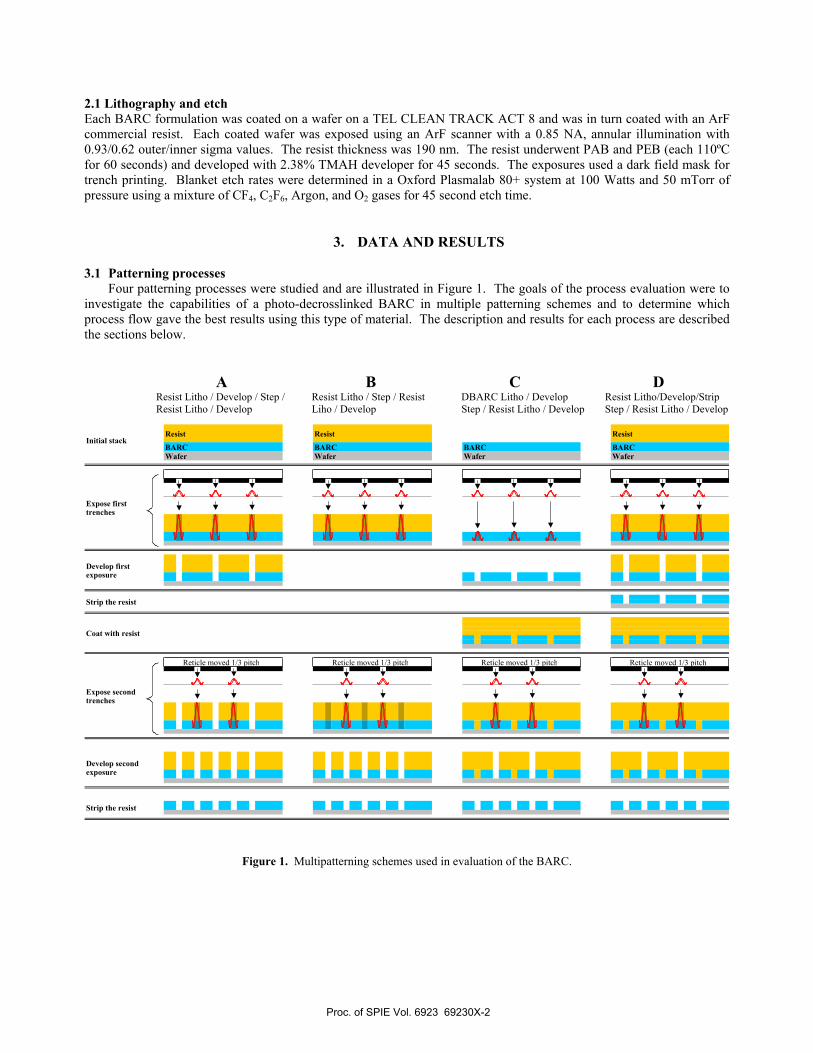
3. DATA AND RESULTS 3.1 Patterning processes Four patterning processes were studied and are illustrated in Figure 1. The goals of the process evaluation were to investigate the capabilities of a photo-decrosslinked BARC in multiple patterning schemes and to determine which process flow gave the best results using this type of material. The description and results for each process are described the sections below. A B C D Resist Litho / Develop / Step / Resist Litho / Step / Resist DBARC Litho / Develop Resist Litho/Develop/Strip Resist Litho / Develop Liho / Develop Step / Resist Litho / Develop Step / Resist Litho / Develop
Figure 1. Multipatterning schemes used in evaluation of the BARC.
Reticle moved 1/3 pitchReticle moved 1/3 pitch
Resist
BARCWafer
BARC BARC
Resist
Reticle moved 1/3 pitch
Initial stackResist
BARCWafer Wafer Wafer
Expose second trenches
Develop second exposure
Strip the resist
Reticle moved 1/3 pitch
Develop first exposure
Expose first trenches
Strip the resist
Coat with resist
Proc. of SPIE Vol. 6923 69230X-2
Jj 4j
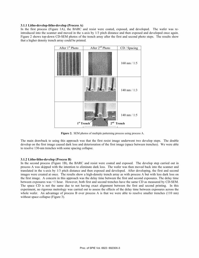
3.1.1 Litho-develop-litho-develop (Process A) In the first process (Figure 1A), the BARC and resist were coated, exposed, and developed. The wafer was re-introduced into the scanner and moved in the x-axis by 1/3 pitch distance and then exposed and developed once again. Figure 2 shows top-down CD-SEM photos of the trench array after the first and second photo steps. The results show that a higher density trench array could be printed.
After 1st Photo After 2nd Photo CD / Spacing
160 nm / 1:5
140 nm / 1:3
140 nm / 1:5
Figure 2. SEM photos of multiple patterning process using process A.
The main drawback to using this approach was that the first resist image underwent two develop steps. The double develop on the first image caused dark loss and deterioration of the first image (space between trenches). We were able to resolve 130-nm trenches with some spacing collapse. 3.1.2 Litho-litho-develop (Process B) In the second process (Figure 1B), the BARC and resist were coated and exposed. The develop step carried out in process A was skipped with the intention to eliminate dark loss. The wafer was then moved back into the scanner and translated in the x-axis by 1/3 pitch distance and then exposed and developed. After developing, the first and second images were created at once. The results show a high-density trench array as with process A but with less dark loss on the first image. A concern in this approach was the delay time between the first and second exposures. The delay time between exposures was <1 hour. However, both first and second trenches have the same CD as measured by CD-SEM. The space CD is not the same due to not having exact alignment between the first and second printing. In this experiment, no rigorous metrology was carried out to assess the effects of the delay time between exposures across the whole wafer. An advantage of process B over process A is that we were able to resolve smaller trenches (110 nm) without space collapse (Figure 3).
1st Trench 2nd Trench
Proc. of SPIE Vol. 6923 69230X-3
LI.LI
II Ii II
Jr 1!
After 2nd Photo CD / Spacing
110 nm / 1:5
110 nm / 1:5
110 nm / 1:5 (Detailed view of above structures)
Figure 3. SEM photos of multipatterning process using process B.
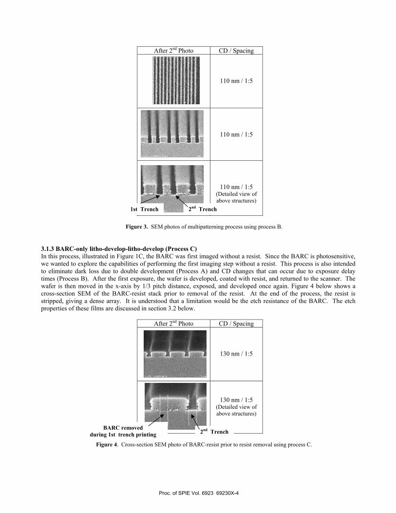
3.1.3 BARC-only litho-develop-litho-develop (Process C) In this process, illustrated in Figure 1C, the BARC was first imaged without a resist. Since the BARC is photosensitive, we wanted to explore the capabilities of performing the first imaging step without a resist. This process is also intended to eliminate dark loss due to double development (Process A) and CD changes that can occur due to exposure delay times (Process B). After the first exposure, the wafer is developed, coated with resist, and returned to the scanner. The wafer is then moved in the x-axis by 1/3 pitch distance, exposed, and developed once again. Figure 4 below shows a cross-section SEM of the BARC-resist stack prior to removal of the resist. At the end of the process, the resist is stripped, giving a dense array. It is understood that a limitation would be the etch resistance of the BARC. The etch properties of these films are discussed in section 3.2 below.
After 2nd Photo CD / Spacing
130 nm / 1:5
130 nm / 1:5 (Detailed view of above structures)
Figure 4. Cross-section SEM photo of BARC-resist prior to resist removal using process C.
2nd Trench 1st Trench
2nd Trench BARC removed
during 1st trench printing
Proc. of SPIE Vol. 6923 69230X-4
Process C main challenge was the ability to obtain good contrast prior to the second patterning step. The imaged BARC film is very thin compared to a conventional resist giving low contrast that caused overlay challenges. After resist strip, we did not obtain good quality SEM images of the dense trench array on the BARC.
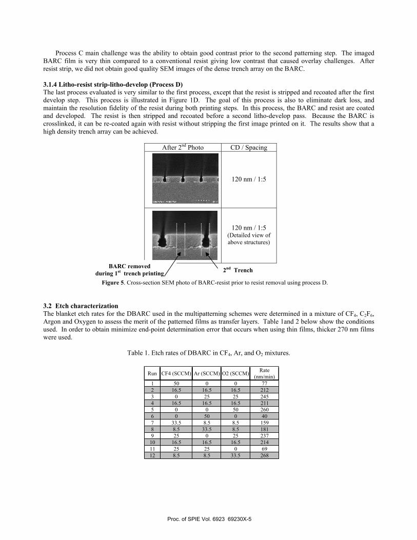
3.1.4 Litho-resist strip-litho-develop (Process D) The last process evaluated is very similar to the first process, except that the resist is stripped and recoated after the first develop step. This process is illustrated in Figure 1D. The goal of this process is also to eliminate dark loss, and maintain the resolution fidelity of the resist during both printing steps. In this process, the BARC and resist are coated and developed. The resist is then stripped and recoated before a second litho-develop pass. Because the BARC is crosslinked, it can be re-coated again with resist without stripping the first image printed on it. The results show that a high density trench array can be achieved.
After 2nd Photo CD / Spacing
120 nm / 1:5
120 nm / 1:5 (Detailed view of above structures)
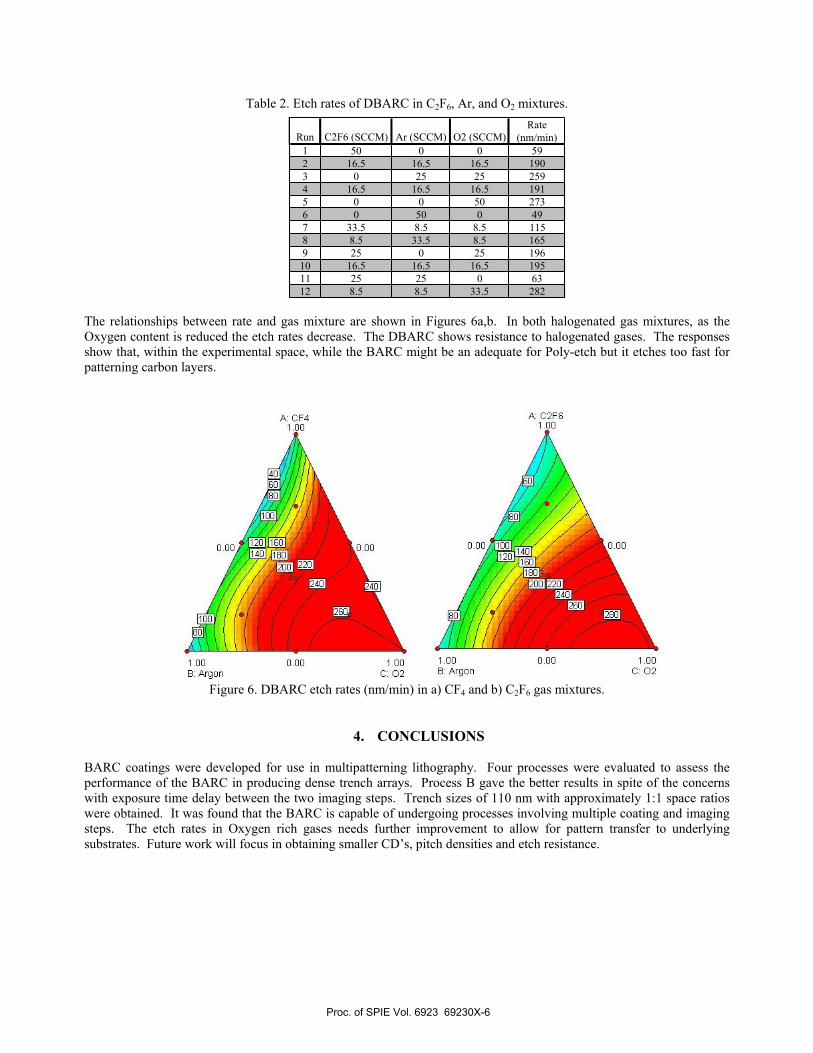
Figure 5. Cross-section SEM photo of BARC-resist prior to resist removal using process D. 3.2 Etch characterization The blanket etch rates for the DBARC used in the multipatterning schemes were determined in a mixture of CF4, C2F6, Argon and Oxygen to assess the merit of the patterned films as transfer layers. Table 1and 2 below show the conditions used. In order to obtain minimize end-point determination error that occurs when using thin films, thicker 270 nm films were used.
Table 1. Etch rates of DBARC in CF4, Ar, and O2 mixtures.
2nd Trench BARC removed during 1st trench printing
Run CF4 (SCCM) Ar (SCCM) O2 (SCCM) Rate (nm/min)
1 50 0 0 772 16.5 16.5 16.5 2123 0 25 25 2454 16.5 16.5 16.5 2115 0 0 50 2606 0 50 0 407 33.5 8.5 8.5 1598 8.5 33.5 8.5 1819 25 0 25 237
10 16.5 16.5 16.5 21411 25 25 0 6912 8.5 8.5 33.5 268
Proc. of SPIE Vol. 6923 69230X-5
1.00B: Argon
A: C2FG
0.00
0.00 1.00C: 02
A: CF41.00
1.00 0.00 1.00B: Arqon C: 02
0.00 .00
Table 2. Etch rates of DBARC in C2F6, Ar, and O2 mixtures.
The relationships between rate and gas mixture are shown in Figures 6a,b. In both halogenated gas mixtures, as the Oxygen content is reduced the etch rates decrease. The DBARC shows resistance to halogenated gases. The responses show that, within the experimental space, while the BARC might be an adequate for Poly-etch but it etches too fast for patterning carbon layers.
Figure 6. DBARC etch rates (nm/min) in a) CF4 and b) C2F6 gas mixtures.
4. CONCLUSIONS BARC coatings were developed for use in multipatterning lithography. Four processes were evaluated to assess the performance of the BARC in producing dense trench arrays. Process B gave the better results in spite of the concerns with exposure time delay between the two imaging steps. Trench sizes of 110 nm with approximately 1:1 space ratios were obtained. It was found that the BARC is capable of undergoing processes involving multiple coating and imaging steps. The etch rates in Oxygen rich gases needs further improvement to allow for pattern transfer to underlying substrates. Future work will focus in obtaining smaller CD’s, pitch densities and etch resistance.
Run C2F6 (SCCM) Ar (SCCM) O2 (SCCM)Rate
(nm/min)1 50 0 0 592 16.5 16.5 16.5 1903 0 25 25 2594 16.5 16.5 16.5 1915 0 0 50 2736 0 50 0 497 33.5 8.5 8.5 1158 8.5 33.5 8.5 1659 25 0 25 196
10 16.5 16.5 16.5 19511 25 25 0 6312 8.5 8.5 33.5 282
6a 6b
Proc. of SPIE Vol. 6923 69230X-6

ACKNOWLEDGMENTS The authors would like to acknowledge the contributions of Nissan Chemical Industries for the use of their facility and equipment to perform the double patterning experiments. Additionally, we would like to thank Dr. Sangwoong Yoon and Takahiro Hamada for assisting in the conceptualization of the double patterning methodologies and for programming and training on the ArF scanner, respectively. The contribution for the etch work by Dr. Hao Xu and Charlyn Stroud of Brewer Science are gratefully acknowledged.
REFERENCES 1. M. Maenhoudt, J. Versluijs, H. Struyf, J. van Olmen, M. van Hove, “Double patterning scheme for sub-0.25 k1
single damascene structures at NA=0.75, λ=193nm”, Proc. SPIE, 5754, 1508-1518, 2005. 2. Hung Jen Liu, Wei Hsien Hsieh, Chang Ho Yeh, Jan Shiun Wu, Hung Wei Chan, Wen Bin Wu, Feng Yi Chen, Tse
Yao Huang, Chiang Lin Shih, Jeng Ping Lin, “Double patterning with multilayer hard mask shrinkage for sub-0.25 k1 lithography,” Proc. SPIE, 6520, 65202J-1 - 65202J-8, 2007.
3. M. Dusa, J. Quaedackers, O.F.A. Larsen, J. Meessen, E. van der Heijden, G. Dicker, O. Wismans, P. de Haas, K. van Ingen Schenau, J. Finders, B. Vleeming, G. Storms, P. Jaenen, S. Cheng, M. Maenhoudt, "Pitch Doubling Through Dual Patterning Lithography Challenges in Integration and Litho Budgets." Proc. SPIE, 6520, 2007.
4. Douglas J. Guerrero, Ramil Mercado, Carlton Washburn, and Jim Meador, “Photochemical Studies on Bottom Anti-Reflective Coatings,” J. Photopolym. Sci. and Technol., 19, No. 3, pp. 343-347, 2006.
5. Carlton Washburn, Alice Guerrero, Ramil Mercado, Douglas Guerrero, and Jim Meador, “Process development for developer-soluble bottom anti-reflective coatings (BARCs),” INTERFACE 2006: Proceedings of the 43rd Microlithography Symposium, October 29-31, 2006.
6. Carlton Washburn, Ramil Mercado, Douglas Guerrero, Jim Meador, “Controlling CD and process window limits for implant patterning,” Solid State Technology, 49, No. 10, pp. 53-56, 2006.
Proc. of SPIE Vol. 6923 69230X-7