Embed Size (px)
Citation preview

Distributed by
Any reference to Raytheon or RTN in this manual should be
interpreted as Raymarine. The names Raytheon and RTN
are owned by the Raytheon Company.

Autohelm’
RADAROperation and
Installation
ST50 PLUS RADAR Operation and Installation Handbook
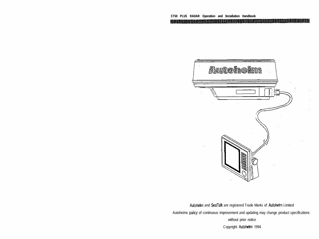
Autohelm and SeaTalk are registered Trade Marks of Autohelm Limited
Autoheims poiicy of continuous improvement and updating may change product specifications
without prior notice
Copyright Autohelm 1994
ST50 PLUS RADAR Operation and Installation Handbook
Warning
This radar equipment must be installed and operated in accordancewith the instructions contained in this manual. Failure to do so canresult in personal injury and/or navigational inaccuracies. In particular:
1. HIGH VOLTAGE. The radar display unit contains high voltage.Adjustments require specialized service procedures and tools onlyavailable to qualified service technicians, and there are no userserviceable parts or adjustments. The operator never should removethe display unit covers or attempt to service the equipment.
2. ANTENNA. It is recommended that the radar antenna be mountedabove objects which could interfere with the radar signal such as theflying bridge, large engine stacks, and personnel. This may be difficulton some vessels and in such a case it is recommended that a radarmounting pedestal be used. Always turn off the radar system beforeservicing the antenna or nearby equipment.
3. ELECTROMAGNETIC ENERGY. The radar antenna transmitselectromagnetic energy. It is important that the radar be turned offwhenever personnel are required to come in range of the antenna toperform work on the antenna assembly or associated equipment.When properly installed and operated, the use of this radar willconform to the requirements of ANSI/IEEE C95.1-1992 Standard forSafety Levels with Respect to Human Exposure to Radio FrequencyElectromagnetic Fields, 3 kHz to 300 GHz.
4. NAVIGATION AID. This radar unit is only an aid to navigation. Itsaccuracy can be affected by many factors including equipment failureor defects, environmental conditions, and improper handling or use.It is the user’s responsibility to exercise common prudence andnavigational judgment. This radar unit should not be relied upon as asubstitute for such prudence and judgment.

ST50 PLUS RADAR Operation and Installation Handbook ST50 PLUS RADAR Operation and Installation Handbook
Package Contents
1. Display Unit
2. Scanner Unit
3. Inter unit Cable (15m)
4 . Power Cable
5. SeaTalk Cable
6. Fixing Studs (4 chl)
7. Thumb nuts (4 off)
8. Gasket
9. Template
10. Installation and Operation Handbook
11. Worldwide Service Center book
12. Warranty document

Contents
Contents
Section 1. Introduction ................................................... l - l
1.1 General ................................................................. l-l
1.2 Equipment Features ................................................ 1-2
1.2.1 ST50 Display Unit ........................................... 1-3
1.2.2 Radome Antenna Unit Main Features ................. l-4
1.3 About This Manual .................................................. 1-5
1.4 Specifications ......................................................... l-6
1.4.1 General .......................................................... l-6
1.4.2 Display Unit .................................................... 1-7
1.4.3 Radome Antenna ............................................. 1-9
Section 2. Installation ................................................... 2-1
2.1 General ................................................................. 2-1
2.2 Unpacking and Inspection ....................................... 2-l
2.3 Planning the Installation ........................................... 2-3
2.3.1 Mounting the Display Unit ............................... .24
2.3.1 .l Console Mounting Instruction.. ................ .2-7
2.3.2 Radome Antenna Mounting ............................. .2-8
2.4 Electrical Connection ............................................. 2-16
2.4.1 DC Power Connection .................................. .2-16
2.4.2 External System Interface ............................. .2-17
2.4.2.1 Connection with External Navaids ......... .2-18
2.4.2.2 Installing the XX Heading Sensor.. ......... .2-19
2.4.2.3 Interconnection XX Heading Sensor ...... .2-21
2.4.2.4 Interconnection (INI-100) ...................... .2-22
2.4.2.5 Seatalk/Compass Interface .................. .2-24
2.4.2.6 Raychart 600Xx Interface .................... .2-24

6 ST50 PLUS RADAR Operation and lnstalfation Handbook Radar Glossary
Section 3. Operation ..................................................... 3-1
3.1 Introduction ........................................................... 3-1
3.2 Radar Map ............................................................. 3-2
3.2.1 Map Operation ............................................... .3-2
3.2.2 Effect of Ship’s Movement .............................. .3-3
3.2.3 Navigational Echoes ....................................... ,3-3
3.2.4 Sea Return .................................................... .34
3.2.5 Storm and Rain Squall Returns ........................ .3-4
3.2.6 Blind Sector or Shadow Effect ........................ .34
3.2.7 Side Lobes .................................................... .3-5
3.2.8 Rader Interference ......................................... .3-6
3.2.9 False Echoes ................................................. .3-6
3.2.10 Determining Radar Line-of-Sight Range .......... .3-8
3.3 Operating Controls ................................................. .3-9
3.3.1 Layout of the Controls ..................................... 3-9
3.3.2 Functions of the Controls ................................ .3-9
Radar Glossary
The following is a list of abbreviations and acronyms which may beused in the text of the manual.A/D -ALM IN -
ALM OUT -
CPUD/ADELDISPEBLEXPFETFTCI RKMLCDLLM HM NNMPCBPPIP-SPWPWSRRS H MST-BYSTC
TBTDT IV DVRMWPTX-MIT
-
Analog to Digital ConversionAlarm In, also known as the “approach” alarm.For targets approaching a set alarm zone.Alarm Out, also known as the exit alarm.For targets exiting or leaving a set alarm zone.Central Processing UnitDigital to Analog ConversionDeleteDisplayElectronic Bearing LineExpansionField Effect TransistorFast Time Constant, also known as Anti-Clutter RainInterference RejectionKilometerLiquid Crystal DisplayLatitude/LongitudeModulator High VoltageModulator High Voltage ReturnNautical MilePrinted Circuit BoardPlan Position IndicatorParallel to Serial ConversionPulse Width (Length)Pulse Width (Length) SelectionRange Rings (Fixed)Ship’s Heading MarkerStandbySensitivity Time Constant, also known asAnti-Clutter SeaTerminal BoardTime DifferenceTriggerVideoVariable Range MarkerWaypointTransmit

Section 1. Introduction
Section 1. Introduction
1.1 GeneralCongratulations on selecting the Autohelm ST50 LCD Radar for yourradar navigation needs.
Whether you purchased this radar because of its compactness, powereconomy, ease of installation, or long term reliability, one thing iscertain; the moment you turn on your ST50 Display you will know youare seeing a revolutionary new concept in radar technology at work.You are the proud owner of a radar system unmatched within therecreational marine industry.
Radar signals are “stored” on an LCD display with chart like clarity anddetail. A single glance at your Display will give you’s complete andaccurate 360’ radar picture of other vessels, buoys and landfallsurrounding your vessel.
The l/8 NM range scale together with the Offset mode makesnavigating tight channels, rivers, or waterways at night a pleasureinstead of a problem.
The Zoom mode gives you a fast 2 times enlargement of the radarpresentation in the zone you have designated. “Timed TX” mode letsthe radar automatically turn its transmitter “on” and “off” for scans ofthe area around your vessel to save battery power. Set the targetalarm zone to alert you of any radar contacts that have entered yourzone, including any that might have escaped your notice.
Electronic Bearing Line (EBL), Variable Range Marker (VRMIand cursorallow rapid high accuracy target bearing and range measurements.When connected to a GPS or Loran Navigator with proper output dataformat for full function operation, the radar can display your destinationwaypoint on the screen at its bearing and range from your vessel. The,Waypoint feature provides steering reference information to thedestination, and can be used to help locate specific buoys or waypointlandmarks.
When intorfard with the Rm-hart fifM7 XX fnntinnl. the revolutionary. ...“.. .a*.-, ,_“__ . . . . . . . ..- ..- .I -.--. - ___. -.._r.- ,,~
new ability to dsiplay chart information alternately, with the radarpicture, adds simplicity and convenience. The industry standard, C-MAP chart cartography, is used to provide you with highly detailed

ST50 PLUS RADAR Operation and lnstaNation Handbook Section 1. Introduction
chart information, making navigation both informative and exciting.The unique Split Screen Mode allows simultaneous viewing of radarand Seatalk’ Data.
With all of these electronic features and the thoughtful compact andefficient design of this radar, it soon becomes apparent that humanengineering and operational simplicity have been foremostconsiderations in the ST50 product design.
You, the customer, set the high standard for the development of ourproducts.
We trust that you will enjoy many years of excellent performance,reliability, and smooth sailing with your new radar system.
To verify your ownership and warranty registration, you should take afew minutes and fill out your warranty registration card found justinside the front cover of this manual. It is very important that you taketime to fill this card out. The warranty registration card should bereturned to the factory immediately after your purchase in order toreceive full warranty benefits.
1.2 Equipment Features
The ST50LCD Radar system is designed and manufactured to provideease of installation and operation combined with excellent reliability.Some of the many important built-in features of the equipment arelisted below:
1.
2.
3.
4.
5.
6.
7.
Alternate ability to switch between a Radar and a Raychart 600Xxscreen (option).
Arrow Key for quick information access, anyplace on the display.
Waterproof to U.S.C.G standards, allowing for flexibility ofinstallation.
Rugged aluminum housing.
The ability to display destination waypoint.
Multi-language operation (English, French, Spanish, German,Norwegian and Italian.) All six languages are standard within eachsystem which are selectable via a menu prompt.
Automatic Tuning Feature.
8. Interfaces with Autohelm Seatalk instruments, and NAVAIDS,including Autohelm’s Smart Heading Sensor magnetic compass.
9. Basic radar alignments can be performed via menu prompts.
10. Automatic tune, rain, sea clutter and gain controls.
11. Auto-temperature compensated screen to prevent “darkening” insunlight.
1.2.1 ST50 Display Unit
The ST50 display unit uses a monochrome LCD monitor enclosed ina.compact, aluminum, rugged, waterproof cabinet.
The front panel contains all of the operating controls for the radarsystem organized in a combination of controls for precise setting ofthe Gain, Tuning, Sea-clutter, and Rain-clutter for clear and detailedradar presentations and Silicone rubber covered keys to assure fastand accurate selection of key operating functions. The keys arelogically arranged for the operator’s convenience and are well backlitfor nighttime use.
The display unit is designed to be either tabletop mounted, mountedon a bulkhead, or in an overhead console. An optional consolemounting kit is available to provide a professional look to custominstallations into consoles or panels.
All system set-up adjustments are made from the display front panel,negating any requirement to open the display unit cabinet, during theinstallation. Screw drivers and adjustment tools are no longer requiredfor display setups.
WarningThis radar display unit contains HIGH VOLTAGE. Adjustments requirespecialized service procedures and tools only available to qualifiedservice technicians, and there are no user serviceable parts oradjustments. The operator never should remove the radar unit coversnor attemot to service this equioment.
ST50 PLUS RADAR Operation and Installation Handbook
The compact design of the display unit is made possible by the use ofcustom LSI (Large Scale Integrated circuit) components. An LSI typeof “chip” contains, in one package, the equivalent of up to 30integrated circuits. Thus compact size, power efficiency, and fullradar navigation features at an economical price are all “standard” inthe ST50 radar system.
1.2.2 Radome Antenna Unit Main Features
The antenna and transceiver are contained within the 18 inch radomeassembly, the radome is made of AES plastic and has a single-flangemounting. The radome protects the electronic assemblies from theenvironment, yet is transparent to the radar’s RF energy, therebyallowing full performance. A small, flexible interunit cable connects theRadome Unit to the Display Unit.
The radome cover is secured to the pan base by four clamping boltsand is provided with a heavyduty rubber gasket to completely seal theunit from the weather and salt spray.
Inside, the radome features a printed-circuitcard array. This technicallyinnovative antenna provides a narrow 6’ beamwidth for excellent short ;range resolution and high gain in a very compact antenna package.
The internal X-band transmitter operates at a 2 kW peak power, with ia sensitive micro-integrated circuit (mic) front end receiver. j
The construction of the antenna unit is modularized, so repairs, shouldthey be required, can be made quickly and cost-effectively.
Section 1. Introduction
1.3 About This Manual
This manual contains important information to help you get the bestoperation and performance from your new ST50 and its associatedoptional equipment. Although the unit is actually pretty simple tomaster, please take the necessary time to read through each section.
Section 2 containsveryimportantinformationon the proper installationof your new ST50 Radar. Although the typical installation might seemstraight forward and simple, we highly recommend that this section beread thoroughly and the guidelines for installation be closely followedto obtain trouble-free and efficient operation of your new units.
Section 3 contains a brief discussion of the general principles of radar,along with the operating instructions for the ST50 Radar which willguide you through the unit? operating controls and display layouts. Tomore easily recognize how to enable the various operations, thenames of the keys that must be pressed to complete the describedoperation are enclosed i n boxes, such asml , or -1. In most cases, pictures, showing the correctdisplays to obtain the desired entry, are included next to each function.
The best way to learn about your ST50 is to dive right in. You can’tdamage the unit by randomly pressing keys. So don’t be afraid toexperiment. In Menu mode, if at any time the results appear confusing,just push themhey twice in order to return to the Main menu, andstart again.
In the event that your ST50 should ever experience an operationalfailure, it is recommended that all repair services be provided by anauthorized service dealer or by the Factory Service Center.

1 - 6 ST50 PLUS RADAR Operation and fnstallation Handbook
1.4 Specifications
1.4.1 General
1) Maximum range: 16 nautical miles2) Minimum range: Less than 35 m (25 yds) on the
.125 nm range.3) Range Scales: Range Number of Range ring
rings interval0.125 nm 2 0.0625 nm0 . 2 5 n m 2 0 . 1 2 5 n m0.5 nm 2 0.25 nm0 . 7 5 n m 3 0.25 nm1.0 nm 4 0.25 nm1.5 nm 6 0.25 nm3 nm 6 0.5 nm6 nm 6 1 nm
12 nm 6 2 nm16 nm 4 4 nm
4) Range discrimination: Less than 35 yds.5) Range ring accuracy: Better than f 1.5% of maximum range of
the scale in use, or 22 m, whichever isthe greater.
6) Bearing accuracy: + 1 degree.7) Display device LCD: Diagonal 168 mm (6.6’)
Effective display area 134.4 x 100.8
;n5fl x 3.9’)8) Environmental conditions:
Radome: Temperature -15-C to +55-CHumidity Up to 95% at 35-C
Display Units: Temperature -10-C to +55’C (EXCEPTLCD)Temperature O’C to +40-C (LCD)Humidity Up to 95% at 35-C
9) Input power requirements: 10.2 m 16V dc10) Power Consumption: 30 W
Note: LCD performance will be slightly deteriorated in responsespeed and brightness during extreme low temperatures.
Section 1. Introduction
1.42 Display Unit
1)
2)
3)4)
5)6)7)
Dimensions:
Mounting:
Weight:LCD:
Width 208 mm (8.2’)Depth 68 mm (2.7’)Height 198 mm (7.8’)without bracketTable, bulkhead, overhead or flushmountingApprox. 1.8 kg (Approx. 4 Ibs)7’ equivalent display area (6.61’diagonal)Contrast: Auto temperature, sensingcompensation
Video 4 levels quantitized.Display Resolution: 320 x 240 pixelsBearing synchronizing system: Motor Encoder
8) Tuning:9) Bearing scale:10) Ship’s heading marker:11) VRM:
12) EBL:
13) EBL Resolution:14) Alarm:15) Off Center
16) Zoom
17) Timed TX
Auto/Manual360’ scale graduated at intervals of 10’ElectricalDigital readout on LCD in the range of0.00 to 16.0 nm, 3 digit Digital-On-Screen-DisplayDigital readout on LCD in the bearing of0’ to 360’, 3 digit Digital-On-ScreenDisplay1’Audible alarm and zone mark on PPIUp to 66% radius (all ranges, except 16nm range scale)X2 enlargement any range except l/8nm scale.Rotation Period Select 10, 20 or 30ScansRepetition Period Select 3, 5, 10 or 15Minutes

l - 8 ST50 PLUS RADAR Operation and Installation Handbook
18) Features
Other Optional Features:
19) Control Keys(All push bottons)
inputs:Loran-C/GPS
Seatalk
Cursor, VRM, EBL, Interference Rejection,Target Expansion, Target Alarms, LAT/LONG or TD Readouts, Waypoint t/L, OffCenter/Zoom, Timed Transmit, Targettrails, Built in Simulator, Hold Mode, AutoGain, Auto STC, Auto FTC, Auto TuneRaychart, Seatalk
RANGE KEYS,TUNE KEYSRAIN KEYSSEA KEYSGAIN KEYSHOLD KEYMENU KEYGUARD KEYEBL KEYVRM KEYCURSOR KEYCTR/ZOOM KEYCONT/DIM KEYSTBY/XMIT KEY
UP/DOWNUP/DOWNUP/DOWNUP/DOWNUP/DOWNOFF/ONOFF/ONOFF/ONOFF/ONOFF/ONOFF/ONOFF/ONOFF/ONOFF/ON
A, v’, 4, b, DIRECTION KEYS
NMEA0183, must include GLL, GTD, VTG,BWC, or RMA and RMB, or RMB and RMCsentences for full function displays andcapabilities.Magnetic Sensor NMEA 0183 HDM, HDT,VHW or HSC, data sentences.Wind Direction, Wind Velocity, Depth, SOG/COG, MTW, Position, Waypoint, Tide, etc.
20) Rear Panel Connectors:Inter-unit (Ant.1 lo-pinPower DC input/ 4-pinN M E ACompass/Seaiaik i-pinRaychart B-pin (option)
Section 1. Introduction
1.4.3 Radome Antenna
1)
2)3)4)
5)6)7)8)9)
Dimensions:
Weight:Polarization:Beam width:
Sidelobes:Rotation:
Diameter of radome 450 mm (17.7’)Height 227 mm (8.9’)Base Dimensions Front to end
270 mm (10.6”)Width200 mm (7.9’)
Approx. 5.5 kg (12.1 Ibs)HorizontalHorizontal 6’ nominalVertical 25’ nominal-21 dB or greater (within +lO’)Approx. 24 RPM
Drive motor input voltage:Transmitter frequency:Peak power output:
10) Transmitter device:11) Pulse length/Pulse
repetition frequency:
12) Modulator:13) Duplexer:14) Mixer:15) IF amplifier:
16) Noise figure:17) Characteristic:
+12 VDC9445k30 MHz2.0 kWMagnetron (RMC-21O.O8ps/2250 Hz(0.125, 0.25, 0.5, 0.075 nm)0.3 p/l200 Hztl, 1.5 nm)0.8 p/600 Hz (3,6, 12, 16 nm)Solidstate modulator driving magnetronT-junction with diode limiterMIC front endCenter frequency 60 MHzBandwidth 7 MHzLess than 10 dBLinear

Section 2. Instal/ation
Section 2. Installation
2.1 General
Congratulations on selecting the Autohelm ST50 LCD radar to meetall of your radar navigation requirements.
Although your ST50 radar is designed to the highest levels of qualityand performance, it can only attain those standards when a properinstallation of the equipment has been achieved.
This section provides practical guidelines to assist in the planning andinstallation of the ST50 aboard your vessel.
2.2 Unpacking and Inspection
Use care when unpacking the ST50 radar from the shipping carton toprevent damage to the contents. It is also good practice to save thecarton and the interior packing material until the radar has beensatisfactorily installed on the vessel. The original packing materialshould be used in the unlikely event that it is necessary to return theunit for service.

ST50 PLUS RADAR Operation and Installation Handbook
2.3 Planning the Installation
The layout for installing the ST50 radar should be planned to give thebest operation and service aboard your particular vessel. In general,the Radome Unit should be mounted as high as possible above thewaterline. The Display Unit should be installed in a convenient viewingposition near the helm. Keep in mind the optimum viewing angle wheninstalling the display. You may want to apply power in advance ofinstalling the unit so that you can determine a satisfactory viewingangle prior to installation.
Note: In order to maximize the operation of your radar system,it is recommended that the radar antenna be mounted aboveobjects which would interfere with the radar signal. Installationof the radar antenna above such obstacles as the flying bridge,large engine stacks and out of the range of personnel will insuremaximum benefit from your radar system.
A 15 meter (50’) length of Vinyl-covered, shielded, 8 conductor cableis furnished with connect plug and terminal connections forinterconnecting the two main units (Scanner and Display).
This length of cable should be sufficient to complete the cable runrequired on most small vessels. It is recommended that the maximumlength of cable between the Scanner Unit and the Display Unit notexceed 20 meters (60’).
A General System diagram for the ST50 is shown below.
Section 2. Installation 2 - 3
;;
7..>===--r==-----
I----_-
u
:: hlagne!ic’
:! sensor
‘:‘-2 .eY Stable
Heading SanSOr
Fig. 2-1 General System Diagram
2.3.1 Mounting the Display Unit
When planning the installation for your ST50 LCD Display Unit, thefollowing conditions should be considered to insure dependable andtrouble free operation.
1) The mounting location should be easily accessible to allowoperation of the front panel controls.
2) There should be adequate ventilation.
31 There should be sufficient space behind the display to allow cableconnections to the rear panei connectors.
4) The Display Unit should be located near a DC power source.
ST50 PLUS RADAR Operation and Installation Handbook
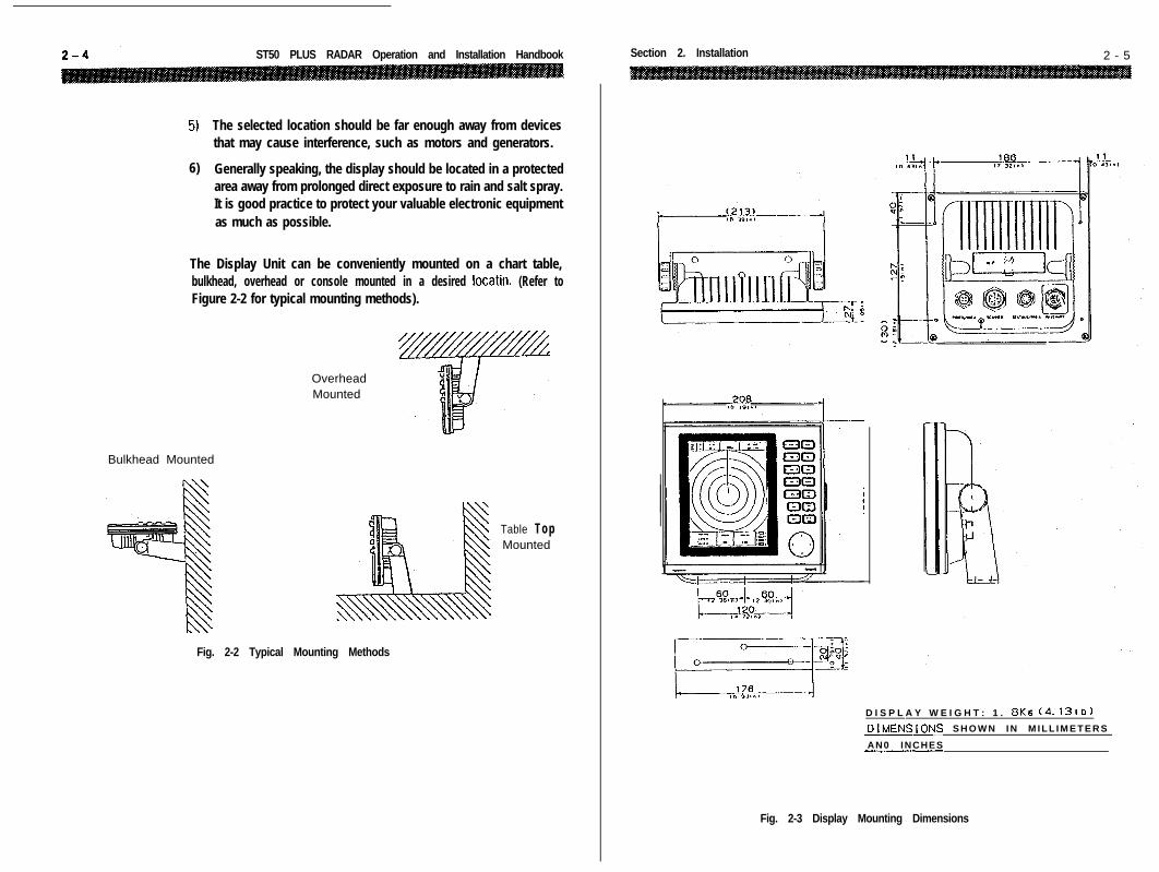
5) The selected location should be far enough away from devicesthat may cause interference, such as motors and generators.
6) Generally speaking, the display should be located in a protectedarea away from prolonged direct exposure to rain and salt spray.It is good practice to protect your valuable electronic equipmentas much as possible.
The Display Unit can be conveniently mounted on a chart table,bulkhead, overhead or console mounted in a desired locatin. (Refer toFigure 2-2 for typical mounting methods).
Bulkhead Mounted
OverheadMounted
Table TopMounted
Fig. 2-2 Typical Mounting Methods
Section 2. Installation 2 - 5
D I S P L A Y W E I G H T : 1 . 8Ke (4. 131b)
_DIMENSiONS S H O W N I N M I L L I M E T E R S
AN0 INCHES-_.__._-.
Fig. 2-3 Display Mounting Dimensions

2 - 6 ST50 PLUS RADAR Operation and Installation Handbook
2.3.1.1 Console Mounting Instructions
The procedure below can be used to console mount the ST50 Display. ~Refer to the console mounting figure to see how the various hardwareitems are arranged during assembly.
I/
Fig. 2-4 Console Mounting the Display
1. Select the location for the unit. A clear, flat area of at least 8” wideby 9” high having at least 6” of clearance depth behind the panelis required.
CautionMake sure there are no hidden electrical wires or other itemsbehind the desired location before proceeding. Checkthatfree------ C-r -a..-a:..~ . . ..A n.lh,:n,, ic ~\,a;lsJk(PdG;liC:JD I”, ,,wur,n,,g Pll” ua”,,,,6 I* “.“..“I.“.
Section 2. lnstaflation 2 - 7
2. Unpack the template mounting kit and also confirm that allhardware is present.
3. Using the instruction template supplied with the kit, trace out theappropriate screw hole locations for flush mounting including thedisplay unit opening.
4. Drill a l/2’ pilot hole in each opposing corners of the cut-out area.
5. Using an appropriate saw, cut the outside edge of the cut-out line.
6. Remove the yoke knobs, from the display cabinet. Check that theunit will fit into the cut-out area.
7. Complete the installation of the DC power cabling, antenna cable,data input, ground, and any other accessory cables, into theconsole.
8. Slide the unit into the cutout of the panel. A suitable sealant maybe used between the trim ring and console to prevent moistureentry.
9. Use the hardware supplied in the kit to secure the unit to theconsole. Tighten the hardware as necessary. Connect all cablesto the unit rear panel.
2.3.2 Radome Antenna Mounting
Selecting the best location for the Scanner Unit requires carefulconsideration. On many small vessels, the unit can be installed on amast platform, on an arch, or on bridge structure. Since radarbasically operates at line-of-sight, the unit should be mounted as highas possible on the vessel to obtain the best long range performance.
The scanning beam should not be obstructed by surrounding largeobjects. Try to locate the radome unit where other large structures orequipment such as searchlights, horns, or masts are not in the samehorizontal plane, otherwise, blind areas and false targets can appearon the radar screen.
Installation near the top of exhaust stacks must be avoided as damageto the radome could result excessive heat and the corrosive effectsn f Ct3f-k cl2crx“I .s~U”I. D...-.....
2 - 8 ST50 PLUS RADAR Operation and Installation Handbook
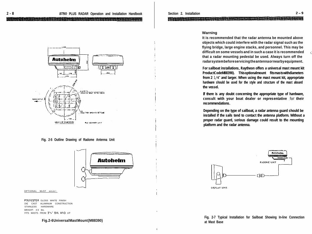
Fig. 2-5 Outline Drawing of Radome Antenna Unit
OPTIONAL MA ST MOUNT :
POCYESTEA GLOSS WHITE FINISH
DIE CAST ALUMINUM CONSTRUCTION
STAINLESS HARDWARE
WEIGHT: 4.5 tbs.
FITS MASTS FROM 2’1:‘ OIA AF;D UP
Fig. 2-6 Universal Mast Mount (M88390)
Section 2. Installation
WarningIt is recommended that the radar antenna be mounted aboveobjects which could interfere with the radar signal such as theflying bridge, large engine stacks, and personnel. This may bedifficult on some vessels and in such a case it is recommendedthat a radar mounting pedestal be used. Always turn off theradar system before servicing the antenna or nearby equipment.
For sailboat installations, Raytheon offers a universal mast mount kitProductCodeM88390). Thisoptionalmount fitsmastswithdiametersfrom 2 l/4’ and larger. When using the mast mount kit, appropriatehardware should be used for the style and structure of the mast aboardthe vessel.
If there is any doubt concerning the appropriate type of hardware,consult with your boat dealer or representative ,for theirrecommendations.
Depending on the type of sailboat, a radar antenna guard should beinstalled if the sails tend to contact the antenna platform. Without aproper radar guard, serious damage could result to the mountingplatform and the radar antenna.
Fig. 2-7 Typical Installation for Sailboat Showing In-line Connectionat Mast Base

ST50 PLUS RADAR Operation and Installation Handbook
Using the outline drawing of the Scanner base or template in the backof the manual as a guide, prepare the mounting surface with the fourmounting holes as required. Install the Scanner and secure it to themounting surface. The correct mounting hardware is stainless steelhexhead bolts 5/16’, 1 l/4’ long with 18 UNC thread. A flat and lockwashers should be used. The Scanner should be parallel to the ship’swaterline and oriented so the cable inlet is pointed AFT.
ANTENNA. It is recommended that the radar antenna be mountedabove objects which could interfere with the radar signal such as theflying bridge, large engine stacks, and personnel. This may be difficulton some vessels and in such a case it is recommended that a radarmounting pedestal be used. Always turn off the radar system beforeservicing the antenna or nearby equipment.
Caution:When mounting the scanner unit, please observe a minimummounting surface thickness of .25 inches. If the thickness ofthe mounting base is too thin, the modulator PCB couldpotentially be damaged (Fig. 2-8). The mounting base shouldbe at least0.25 inches thick. Use additional washers if necessaryto meet this requirement.
P.S ./Modulator PC0% 2
linch Mar
Thickness Mounling bx.o(min. thickness 0.25 inch)
Plain washer
Cock washor
S~aioloss stcci bob
5116.10UNC
,
II
I,I
/
,
II
!
I
I
I
I
/
I
I
I
Section 2. Installation
Some vessel’s however, may adopt a HIGHER BOW angle when thevessel is at it’s cruising speed that substantially alters and raises theradar’s main radiation plane. In this case nearby target detection mightbe poor. It may be helpful to lower the radar beam towards the parallelby shimming the radar pedestal to tilt the beam angle slightlydownward with respect to the waterline.
The figure shows one approach, that of using an angled wood blockbetween the pedestal mounting feet and the mast or platform surfaceto obtain the desired tilt angle. The shims may also be made fromaluminum plate wedges or simple flat washers.
Setting the RadiationPlaneIn the standard antennainstallation the scanner/pedestal unit is mounted sothe array will rotate parallel tothe waterline. The beam ofthe radar is approximately 25”wide in the vertical directionso target detection during thevessel’s pitching and rollingwill be generally good.
,OEAL RADIATION PlANE
Fig. 2-8
2- 12 ST50 PLUS RADAR Operation and installation Handbook
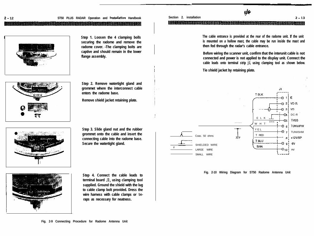
I I Step 1. Loosen the 4 clamping bollssecuring the radome and remove theradome cover. -The clamping bolts arecaptive and should remain in the lowerflange assembly.
Step 2. Remove watertight gland andgrommet where the interconnect cableenters the radome base.
Remove shield jacket retaining plate.
Step 3. Slide gland nut and the rubbergrommet onto the cable and insert theconnecting cable into the radome base.Secure the watertight gland.
Step 4. Connect the cable leads toterminal board Jl, using clamping toolsupplied. Ground the shield with the lugto cable clamp bolt provided. Dress thewire harness with cable clamps or tie-raps as necessary for neatness.
) Section 2. installation
The cable entrance is provided at the rear of the radome unit. If the unitis mounted on a hollow mast, the cable may be run inside the mast andthen fed through the radar’s cable entrance.
Before wiring the scanner unit, confirm that the interunit cable is notconnected and power is not applied to the display unit. Connect thecable leads onto terminal strip JI, using clamping tool as shown below.
Tie shield jacket by retaining plate.
I
A
AlI----- - - - -T
Coax. 50 ohms
E L K -R.
- - - - - / W H T ---. ;
’ Y E LI 0III @
T RED III -
SHIELDED WIRE
LARGE WIRE
SMALL WIREI-----J
Fig. 2-10 Wiring Diagram for ST50 Radome Antenna Unit
DC-R
Tl/GS
TUNVIPW
TUNIISHM
+12V/BP
-0V
HV
Fig. 2-9 Connecting Procedure for Radome Antenna Unit
ST50 PLUS RADAR Operation and Installation Handbook
_-------------------_DISPLAY UNIT ;
I
H V
-SV
E
VD
E
E
TUGS
TUNVIPW
TUNI/SHM
+lZV/BP
+DC
- D C
+NMEA
-NMEA
,______--_--________------ ------II, ANTENNA UNIT II1 1I 1# II T ELK I8 II 01 E II It @ 2 VD-R 8I
1COAX. 4
8 w 03 V D ,
II
I II I a 4 DC-R
i I 1I
I I~-~~-~~~~_-~~~~~_-~~--_----J
+TO SHIP’S POWER
II 5: LARGE WIRE------------------J
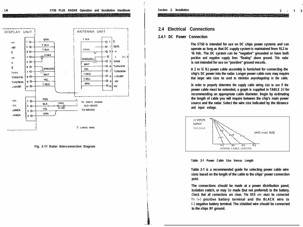
Fig. 2-11 Radar Interconnection Diagram
Section 2. Installation 2 - 1 5
2.4 Electrical Connections
2.4.1 DC Power Connection
The ST50 is intended for use on DC ships power systems and canoperate as long as that DC supply system is maintained from 10.2 to16 Vdc. The DC system can be “negative” grounded or have bothpositive and negative supply lines “floating” above ground. This radaris not intended for use on “positive” ground vessels.
A 2 m .I6 ft.) power cable assembly is furnished for connecting theship’s DC power into the radar. Longer power cable runs may requirethat larger wire sizes be used to minimize anyvoltagedrop in the cable.
In order to properly determine the supply cable wiring size to use if thepower cable must be extended, a graph is supplied in TABLE 2-l forrecommending an appropriate cable diameter. Begin by estimatingthe length of cable you will require between the ship’s main powersource and the radar. Select the wire size indicated by the distanceand input voltage.
12VOLTS -LLPIJT
V O L T A G E
AWG WIRE SIZE
POWER CABLE LENGTH
Table 2-1 Power Cable Size Versus Length
Table 2-1 is a recommended guide for selecting power cable wiresizes based on the length of the cable to the ships’ power connectionpoint.
The connections should be made at a power distribution panel,isolation switch, or may be made (but not preferred) to the battery.Check that all connections are clean. The RED wire must be connectedto !+I positive battery terminal and the BLACK wire to(-1 negative battery terminal. The shielded wire should be connectedto the ships RF ground.

2- 16 ST50 PLUS RADAR Operation and installation Handbook
Should the power connections be accidently reversed, protective in-line fuse F401(3.15A) will blow. Make sure that the input power leadsare connected for correct polarity with a VOM. Replace the fuse.
Grounding the Radar SystemIt is important for proper operation that an effective RF ground beconnected to the radar system. You may elect to ground the radar byconnection of a 10 or 12 gauge wire to the ground on the rear of thedisplay to be connected to the nearest ground point of the ship’s RFground system.
2.4.2 External System Interface
I l-l
Fig. 2-12 Display Rear Chassis
Section 2. Installation
The ST50 radar can receive various input signals from Navaids, FluxSensors, Raychart Units, and Seatalk Data networks. Thk inputs fromSeatalk, the flux sensor, and Navaids will be digital data conforming tothe NMEA 0183, or Seatalk formats to drive various radar featuressuch as Waypoint Mode.
If more than one data type is present at the radar inputs (for example;Flux Sensor and NMEA and Seatalk) a system priority has beenestablished in the radar’s software to respond to the inputs in drivingthe features.
The assigned priorities are set in this manner:
HEADING: 1. Flux Sensor (NMEA 0183 “HDM, HDT, HSC”)2. Seatalk Data (Heading via Autopilot compass)3. Navaid Data (NMEA 0183 “RMC, RMA VTG”)
POSITION: 1. Seatalk Data
2. Navaid Data (NMEA 0183 “RMC, RMA, GLL, GTD”)
SPEED: 1. Navaid Data (NMEA 0183 “RMC, RMA, VTG, VHW”)
WAYPOINT: 1. Seatalk Data2. Navaid Data (NMEA 0183 “RMB, BWC”)
SEATALK: Seatalk Data only
2.5.2.1 Connection with External Navaids
Navaid data is the primary sourcefor position, speed, and waypointbearing and rangeinputinformationto the radar. Check the list aboveand verify that the Navaid that willbe used to supply data input to theradar contains the requiredsentencesinilsNMEA0183output.The Navaid input should beconnected at the NMEA connectorJ401, Pin 3 (DATA +) and pin 4h-u7-n \\YnIn-,.
POWER/NMEA CHASSISCONNECTOR (J401)View from the rear the display.
(1> I’UWtK UC li?V + (KtU)@ POWER DC 12V - (BLKI@ NAV DATA IN + (YEL)@ NAV DATA IN - (GRN)
.I
! - 18 ST50 PLUS RADAR Operation and Installation Handbook Section 2. Installation 2- 19
If for some reason, NMEA 0183 data is not available from any Navaidson the vessel, the radar can accept and operate in full function with the ISeatalk format.
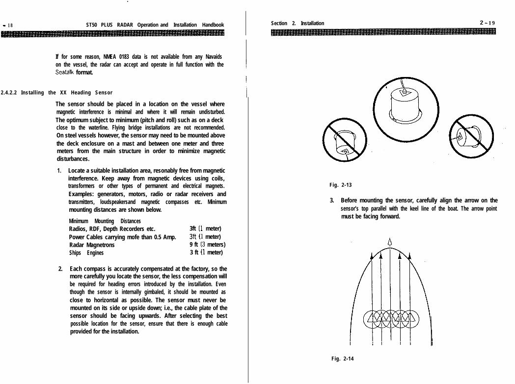
2.4.2.2 Installing the XX Heading Sensor I
The sensor should be placed in a location on the vessel wheremagnetic interference is minimal and where it will remain undisturbed.The optimum subject to minimum (pitch and roll) such as on a deckclose to the waterline. Flying bridge installations are not recommended.On steel vessels however, the sensor may need to be mounted abovethe deck enclosure on a mast and between one meter and threemeters from the main structure in order to minimize magneticdisturbances.
1. Locate a suitable installation area, resonably free from magneticinterference. Keep away from magnetic devices using coils,transformers or other types of permanent and electrical magnets.Examples: generators, motors, radio or radar receivers andtransmitters, loudspeakersand magnetic compasses etc. Minimummounting distances are shown below.
Minimum Mounting DistancesRadios, RDF, Depth Recorders etc. 3ft (1 meter)Power Cables carrying mofe than 0.5 Amp. 3ft (1 meter)Radar Magnetrons 9 ft (3 meters)Ships Engines 3 ft (1 meter)
2. Each compass is accurately compensated at the factory, so themore carefully you locate the sensor, the less compensation willbe required for heading errors introduced by the installation. Eventhough the sensor is internally gimbaled, it should be mounted asclose to horizontal as possible. The sensor must never bemounted on its side or upside down; i.e., the cable plate of thesensor should be facing upwards. After selecting the bestpossible location for the sensor, ensure that there is enough cableprovided for the installation.
Fig. 2-13
3. Before mounting the sensor, carefully align the arrow on thesensor’s top parallel with the keel line of the boat. The arrow pointmust be facing forward.
Fig. 2-14

ST50 PLUS RADAR Operation and Installation Handbook Section 2. Installation
4. Drill a 9/64’ hole in the center of each of the three slotsin the baseof the sensor. These slots will allow you to turn the sensor slightlyto align it with the center line of the vessel during compensation.
5. Using the three#lOstainless steelscrews provided, or three#lObrass screws, secure the sensor in place.
6. Install a terminal strip or junction box (not supplied) in anyconvenient place to allow system interconnection.
7. It is advisable to connect the sensor through a fused supply orcircuit breaker at either an existing switch panel or separate fuseblock. Since the current drain is very low, the sensor could be lefton with very little battery drain. However, it is best secure powerto the sensor when the vessel is not in use. These sensors are notintended for use on “Positive” ground vessels.
2.4.2.3 Interconnection (XX Heading Sensor)
The XX heading sensor is intended for use on vessels with 12 VDCpower systems and can operate between 9.5 (min) and 16VDC (max).The power system can be “Negative” grounded or have both positiveand negative lines “floating” above ground. The sensor is NOTintended for use on “positive” ground vessels.
A 10 foot shielded cable is supplied with the sensor unit. The cablecontains 7 conductors. Two conductors (GRN, ORG) are used tosupply heading data to the radar display and two conductors (RED,BLK) are used to supply 12 VDC ships power to the unit. The unusedconductors (WHT, BRN and BLU) should be insulated and tied back. Itis suggested that the wiring terminate on a suitable terminal strip.Refer to Fig. 2-15, below.
When connecting power to the sensor, OBSERVE PROPER POLARITY!The RED wire should be connected to the Positive (+I source terminal;the BLACK wire should be connected to the NEGATIVE (-1 sourceterminal. If the power leads are reversed the sensor will not operate.
If it appears that the sensor is inoperative, check the input voltagepolarity with a DVM or VOM and if necessary, reverse the wires tocorrect !hp error.
Notes: The sensor is designed to output the NMEA 0183 “HDM”sentence for the radar. The sensor can supply data for up to two (2)external inputs which conform to the NMEA interface requirements.
Ensure that the wiring is as shown in Fig. 2-15, below.
To avoid ground loops DO NOT CONNECT the sensor cable shield togiound.
I, TERMINAL BLOCK
NMEA DATA
DATA COMMOC
BLUI
I -L SHLPJXX Fluxgate Ilcxfirlg Sensor
Fig. 2-15 XX Heading Sensor Wiring
2.4.2.4 Interconnection (INI-100)
The INt-100 intended for use on vessels with 12 VDC power systemsand can operate between 8.5 (min) and 28 VDC (max). The powersystemcan be “Negative” grounded or have both positive and negativelines “floating” above ground. The INI- is NOT intended for use on“positive” ground vessels.
A 10 foot shielded cable is supplied with the INI- unit. The cablecontains 4 conductors. Two conductros (WHT, GRN) are used tosupply heading data to the radar display and two conductors (RED,BLK) are used to supply 12 VDC ships power to the unit. It is suggestedthat the wiring terminate on a suitable terminal strip. Refer to Fig. 2-16, below.

ST50 PLUS RADAR Operation and installation Handbook
-
When connecting power to the sensor OBSERVE PROPER POLARITY!The RED wire should be connected to the POSITIVE (+I sourceterminal; the BLACK wire should be connected to the NEGATIVE f-) source terminal. If the power leads are reversed the sensor will notoperate.
It it appears that the sensor is inoperative, check the input voltagepolarity with a DVM or VOM and if necessary, reverse the wires tocorrect the error.
h TERMINAL BLOCK
I \DATA COMMON
Ml39980L4INt 100
Fig. 2-16 INI- WRING
Notes: The sensor is designed to output the NMEA 0183 “HDM”senstence for the radar. The sensor can supply data for up to two (2)external inputs which conform to the NMEA interface requirements.
Ensure that the wiring is as shown in Fig. 2-16, above.
To avoid ground loops DO NOT CONNECT the sensor cable shield toground.
Section 2. Installation 2-23
2.4.2.5 Seatalk/Compass Interface Connection [J403]
*solder side shown
1 COMPASS E2 COMPASS +123 COMPASS + fnmea data14 COMPASS - [data common15 SEATALK Vcc UO-16Vdcl6 TX-RX SEATALK DATA7 SEATALK - [El
In order to view Seatalk data on the bottom of the ST50 display, asimple connection to your existing Autohelm capable equipment is allthat is required. Once connected, you simply need to select “DISPLAYRADAR SEATALK” by held depressing ml key or from the MAINmenu in order to see the split screen capabilities of the ST50.
An external compass sensor such as a Smart Heading Sensor(M92580) can also be connected to the ST50 display unit as shownabove.
2.4.2.6 Raychart 600Xx Interface Connector [J40-41
‘solder side shown
1 E2 LDO3 LDl4 LD25 LD36 LOAD7 FRAME8 LCD CLK

2 - 24 ST50 PLUS RADAR Operation and Installation Handbook
In order to access the full charting and alternate screen operations ofthe ST50 radar, a simple connection between your Raychart 600Xxand the display must be made. If your unit does not have the Raychartoption already installed, then you will need the Raychart option kitMDYW10417.
When the Raychart unit is first turned on, the radar will detect theincoming signals and will switch instantly to the Raychart screen.Pressing the ml key can select the full screen display of thecharting presentation at any time.
MOLDED CABLE END: .!- MOLDED CABLE END:
SHIELD SHIELD
WW
0.w
v-D1)
(LD-4
(LW
(LOAD)
(FRAME)
( L C D C L K ) 6
(SPARE) 9 >:J
Interface Cable 6623011-l
Fig. 2-17 Radar/Raychart interconnection
WWVW
(LDO
(LWKWLOAD (H. SYNC)
FRAME (V. SYNC)
L C D C L K (CLZ)
Section 3. Operation
Section 3. Operation
3.1 Introduction1
2
3
4
5
6
Congratulations on selecting the Autohelm ST50 LCD Radar tofulfill all of your radar navigation requirements.
The ST50 Radar besides being an outstanding Radar System byitself, combines the operation of Chart Plotting with those ofRadar Navigation. This Section of the manual provides thedescriptions and instructions for all of the operations and featureswithin this radar system.
For first time users of Radar we have included some basicinformation on the general principles of how radar works to start,this should provide you with a basic understanding of how thecontrols affect the radars operation ;and display. Part 3.3 of thissection (pg. 3-10) begins the actual description of the front panelcontrols along with an explanation of how they work.
This section begins by describing the keypad layout and thevarious display screens of the ST50 Radar. A fold-out page witha drawing of the display and locations of all the controls anddisplay data is provided on page 3-l 1 (FIG. 3-2) for your referencewhile reading about these controls.
As you are reading through this section of the manual you willnotice that when operations can for keys to be pressed tocomplete entries, the keys are highlighted in key shaped boxes.i.e., m] in the instructinos.
To keep the operation of the ST50 Radar simple and as automaticas possible, the Radar uses many on-screen menus, messages,and prompts to help guide you through various operations. Youshould master the unit very quickly and the approach you shouldtake, while becoming familiar with the operations, is one ofrelaxed confidence.

3 - 2 ST50 PLUS RADAR Operation and Installation Handbook
3.2 Radar Map
The radar display is a map-like representalion of the area in which theradar is operating. Typically, the ship’s position is at the center of thedisplay or sometime may be repositioned or offset up to 66% of theradius anywhere on the screen in the OFFSET MODE. The ship’s deadahead bearing is indicated by the heading line at the 0” bearing withevery revolution of the sweep trace.
Coastline contours are generally depicted in solid filled blue echoareas. Other surface vessels, and channel buoys, are displayed assmaller single echoes. The radar picture or map can be viewed in manysizes or scales from own ship. These sizes are selected by the rangescale controls. Greater detail of radar echoes nearby own ship isshown when using the short range scales. The best technique is tostart with using a longer range scale and then switching to shorterranges when nearby targets appear, or as the ship approaches thecoastline, harbor, or other vessels in the area.
Until the operator becomes familiar with interpreting the radar display,every opportunity should be taken to compare the radars displaypatterns with visual targets, such as other vessels, buoys, coastalstructures etc. Harbor and coastal navigation should be practicedduring daylight with clear weather conditions.
3.2.1 Map Orientation
In the RELATIVE mode, the heading line always appears on the DisplayUnit at 0” relative, and is coincident with the antenna beam passing theship’s bow. Thus the top of the displayed picture represents thedirection in which the ship is heading. All targets appearing on thedisplay are “Relative” to own ship’s position and heading.
The EBL’s give relative bearing data. When in the TRUE mode, EBLreadouts give true bearing to targets. The MAGNETIC mode providesmagnetic bearings to targets.
Acompass input is required inorder to have magnetic bearings. AGPSor Loran input is required in order to have true heading. Some GPS andLoran units allow for the input of magnetic variation into them, whichin turn, will provide magnetic course information to the radar.
Section 3. Operation
3.2.2 Effect of Ship’s Movement
Radar Displays can be drawn in two ways to show the ship’s motion,The displays are called “Relative Motion” and ‘True Motion” Display. InRelative Motion, the most common radar display mode the appearance’of the radar display changes according to the ship’s speed and course,that is own ship is permanently fixed in position but radar echoes(targets) move in relation to your vessel. With no movement of the ship,a steady display of fixed radar echoes is shown. If the ship is movingahead on a constant course, echoes appearing at the top of the displaywill move downward across the display. Your position will alwaysremain at the center of the display.
If your vessel alters course to the right, the displayed echoes will bedisplaced by an equal amount in bearing in a counterclockwisedirection, and vice versa. These changes in the display pattern withship movement is an extremely important factor when plotting theship’s course and the courses of nearby vessels.
The True Motion Display Mode is very much like seeing your vesselmoving on a map or chart. In True Motion, the surrounding landmassechoes will remain stationary on the screen. If your ship is moving ata constant course and speed, you will see your position move acrossthe screen towards the edge of the display. Any other targets whichare underway will also be moving on the display screen at their Truecourse and True speed. All motion seen on the True Motion display is“TRUE”. (meaning motion over the ground).
The ST50 Radar only operates in the Relative Motion mode.
3.2.3 Navigational Echoes
Echoes displayed on the radar screen may be large or small, bright orfaint, depending on the size of the object. The radar indication may notbe similar to an observer’s visual indication; a nearby small object mayappear to be the same size as a distant large object on the radar. Withexperience, however, the approximate size of different objects can bedetermined by the relative size and brightness of their radar echoes.

ST50 PLUS RADAR Operation and Installation Handbook
Buoys and small boats are an example of targets that are sometimesdifficult to differentiate between. Since they bob and toss about in thewaves, they do not present a consistent reflecting surface.Consequently, their echoes have a tendency to fade and brighten andat times to disappear momentarily. Very often buoys and small boatsresemble each other, but usually the motion of one target to the otheridentifies the boat from the buoy.
High coastlines and mountainous coastal regions can be observed atthe longest range of the radar. However, the first sight of landfall onthe radar display may be a mountain several miles inland from thecoastline. The actual coastline may not appear on the radar until thevessel has closed the range to the land near the line of sight distance.
3.2.4 Sea Return
Not all radar echoes are produced by hard navigation items such asboats, buoys and land. Some Radar echoes may be received fromirregularities on the surface of the water, particularly atclose range bybreaking wavecrests in heavy seas. These echoes appear on the PPIscreen usually on the very short range scales as multiple small echoesnot in a repetative or consistant position. Under high winds andextreme conditions the echoes from sea clutter may appear as densebackground of clutter forming the shape of an almost solid disc, as faras one to three miles in all directions from the display center.
3.2.5 Storm and Rain Squal Returns
The Radar can also see echoes from rain or snow. Returns from stormareas and rain squalls consist of countless small echoes, continuouslychanging in size, intensity, and position. These returns sometimesappear as large hazy areas on the display depending on the intensityof the rainfall or snow in the storm cell. The cells usually are visible forlong distances due to their extreme altitude and are very helpful forobserving bad weather warnings. If the returns from storm areas andrain squalls are not desired, the RAIN control can be adjusted tominimize them.
Section 3. Operation
3.2.6 Blind Sectors or Shadow Effect
Not all echoes on the radar are direct returns to the radar antenna.There are many types of echoes that can appear on the display ifcertain conditions occur. The sections that follow briefly describe theecho patterns that may be produced by these false echoes and theirlikely cause. It should be noted that the Radar operator, throughobservation, practice, and experience can detect these conditionsgenerally very quickly.
Funnels and masts, (when located near the antenna array) may causeshadows. In the shadow area beyond the obstruction there will be areduction of the beam intensity, although not necessarily a completecutoff. However, if the subtended angle is more than a few degreesthere will be a blind sector.
In some shadow sectors the beam intensity may not be sufficient toobtain an echo from a very small object even at close range, despitethe fact that a large vessel can be detected at a much greater range.For this reason the angular width and relative bearing of any shadowsector must be determined at installation. Sometimes shadowing canbe seen by increasing the Radar Gain until noise is present. Darksectors indicate possible shadowed areas. This information should beposted near the Display Unit, and operators must be alert for objectsin these blind sectors.

3 - 6 ST50 PLUS RADAR Operation and Installation Handbook
3.2.7 Side Lobes
A very small part of the RF energy from each transmitted pulse isradiated outside the single narrow beam, producing side lobe patterns.Side lobes have no effect on distant or small surface objects, but theecho from a large object at short range may produce an arc on theradar screen similar to a range ring, or appear as a series of echoesforming a broken arc. Side-lobe echoes normally occurs at a rangebelow 3 miles and can be reduced by adjustment of the SEA control.
Section 3. Operation
3.2.8 Radar Interference
Whenever two or more radar equipped vessels are operating withinreception range of each other, mutual interference is likely. This willusually appear on the screen as a series of small dots, which move toand from the PPI center, sometimes in a straight line, but more oftenin a long, sweeping curve. This type of interference is most noticeablein longer ranges. This should not, as a rule, impair the effectivenessof the radar as a navigational aid. Radar interference can be completelyeliminated by turning IR “ON” on the Display Unit function menu. TheIR feature is normally left “on”.
3.2.9 False Echoes
Occasionally, signals will appear on the screen at positions wherethere is no actual target. These targets are called “False Echoes” andmay be caused by Ghost Images, Indirect Echoes or Multiple Echoes.
There are several types of ghost images. They sometimes have theappearance of true echoes, but in general they are intermittent andpoorly defined. A ghost image retains a fixed relationship with respectto the true image and has a more arc-like appearance with a tendencyto smear. They are sometimes caused by targets which have a wide,smooth surface near your own ship.

3 - 8 ST50 PLUS RADAR Operation and Installation Handbook
Indirect echoes may appear when there is a large target, such as apassing ship at a short range, or a reflecting surface, such as a funnelon your own ship in line with the antenna. The signal, on first strikingthe smooth side of the large target, will be reflected, and thesesubsequent echo returns to the antenna are shown on the display.However, the same reflection hits other masts or obstacles and thengets picked up by the radar antenna with enough strength to appearas a target on the radar screen.
TiiUE ECHO
lNOlRECT ECHO
PASSING SHIP
INOliiECT ECHO
Multiple echoes could appear if there is a large target having a widevertical surface to your own ship at a comparatively short range. Thetransmitted signal will be reflected back and forth between the widevertical surface of the target and your own ship.
Thus, multiple echoes will appear beyond the true target’s echo on thesame bearing as shown below. This is not a very common phenomena.
Section 3. Operation
3.2.10 Determining Radar Line-of-Sight Range
When searching for distant echoes, the radar line-of-sight range to theecho can be a limiting factor. Radar waves behave like light waves butare refracted slightly more, increasing the distance to the radarhorizon to slightly beyond the optical horizon (displayed range iscorrect, however). As Fig. 3-1, below, shows, the radar line-of-sightrange is a combination of the radar horizon of the ship’s radar antennaand the radar horizon of the target. The nomograph shown in Fig. 3-1, below, provides a convenient method of determining any of thethree factors involved when the other two factors are known.
ai. a2: in naudcal miles
hl. hz: in feer
Fig. 3-l Radar Line-of-Sight Range Nomograph
The distance to the radar horizon from the radar antenna of height “h”meter, under standard conditions, may be calculated from the formula
Distance (nm) = 2.23 fi
For example, an antenna at a height of 5 meters has a radar horizonof 5.0 nm.
ST50 PLUS RADAR Operation and Installation Handbook
A 5 meter cliff has a radar horizon of 5 nm. Therefore, under standardconditions, the cliff should begin to appear on the screen when the shipcomes within 5.0 + 5.0 = 10 nm.
3.3 Operating Controls
Generally the operation of the ST50 is easy and straight forward.However, the navigator who takes the time to become fully familiar withthe panel layout and understands the functions of the various controlswill be able to obtain the best performance from his equipment.
3.3.1 Layout of the Controls
The layout of controls is shown in Figure 3-2.
3.3.2 Functions of the Controls
r-iJ ‘POWER’ STBY/XMlT KEY
In the “OFF” state no power is applied to the radar system. UponPressing the STBY/XMIT key, ship’s DC power is applied to thescanner and display units. The radar normally requiresapproximately 90 seconds to warm up. A countdown timer on theradar display shows the time remaining in the warm up period.During the warm-up period the radar transmitter does not operateand antenna does not rotate.
After the warm up period, one beep will sound and “PUSH XMITTO OPERATE” will be displayed on the screen.
The display will also show the operating time (hours) of the radarduring the warm up period, as well as the software level (i.e. vl .O).
The radar is now available for operation.
Pressing the STBY/XMIT key puts the radar into the “transmit’mode. The antenna will begin rotation, and targets will bedisplayed on the screen.
If the STBY/XMIT key is pressed again, the radar will return to the“stand-by” condition with the transmitter OFF and the “PUSH XMITTO OPERATE” indication again appears on the screen.
Section 3. Operation
By pressing and holding down the STBY/XMIT key indicationapproximately 2 seconds, the radar will be turned OFF and allalphanumeric information on-screen will extinguish.
@-I RANGE KEY
By pressing the UP (Right side) or DOWN (Left side) of the key, thedesired range scale can be selected.
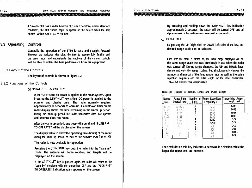
Each time the radar is turned on, the initial range displayed will bethe same range scale that was previously in use when the radarwas turned off. During range changes, the UP and DOWN keyschange not only the range scaling, but simultaneously change thenumber and interval of the fixed range rings as well as the pulserepetition frequency and the pulse length for the radar transmitter.Table 3-1 shows this relationship.
Table 3-l Relation of Range, Rings and Pulse Length
Rangetrim)
0.1250.250.50.751.01.5361 21 6
0.06250.1250.250.250.250.250.5
24
Range Ring Number of Pulse Repetition Transmitting Pulse 1Interval trim) Rings Frequency (Hz)
225022502250225012001200600600600600
The small dot on this key indicates a decrease in selection, while thelarger dot represents an increase.

ST50 PLUS RADAR Operation and Installation Handbook
Note: Pressing the [G-l key at the same time while turningthe radar to standby will perform a Soft Master Reset to the unitin the event that a “lock up” condition should occur. A SoftMaster Reset will NOT reset the radar’s initial settings (i.e.bearing, STC, tune, timing . ..). In order to perform the SoftMaster Reset, shut the Radar System OFF. Hold downthe -1 key; then-press the[m! key to place the unit inST-BY. Release the F] key. The Master Reset conditionis verified by observing that the total hour meter is reset toOOOOHrs.
A Hard Master Reset can also be performed. This type of resetwill clear all memory including the radar’s initial settings. Toperform a hard master reset press-1 Then press theIm[ key. Releaset h e 1-1 k e y a n d t h e n t h e [?QWiGKjkey in order to Hard Reset the radar.
Section 3. Operation
0
0
TUNE CONTROL
The tune control is used to tune the receiver in the antenna unitfor maximum targets on the display. If there are no targetsavailable, this control can be used to tune for maximum seaclutter. The on-screen tune level indicator will show the tuningpeak condition by displaying a maximum deflection to the right.The tuning adjustment of the radar should be normally performedon the longer range scales from 3 to 16 nm but should always be-rechecked for peak indication on the range scale you are using.Tuning is controlled by pressing the tune left or right keys formaximum bars.
The minimum deflection of the tuning indicator will occur whenthere are few or no targets. Minor retuning of the radar may benecessary after the radar has warmed up 10 minutes. The 10minutes accounts for time to allow the magnetron frequency tostabilize.
AUTO TUNE MODEThe Radar includes an Automatic TUNE Feature. In the Automaticmode, the radar tunes itself automatically on all range scales.Auto Tune is available by pressing thell key Cl+). Use theArrow key to Select Tune . . . Auto with the highlighted Cursor.Pressmj to activate Tuning Mode. The Manual mode isindicated by the “Tuning Bar”and the Automatic mode is indicatedby an “A” after it.
RAIN CLUTTER CONTROL
The Auto or Manual rain clutter control, also known as Fast TimeConstant (FTC), is used to reduce large undesirable echoes fromclutter such as rain or snow which may obscure smaller echoesin their vicinity. The rain clutter control is normally adjusted toreduce such echoes so that only the leading edges of the largerechoes are displayed, while the smaller echoes are only slightlyeffected. To reduce rain or snow target pickup, press theI-key until rain details are reduced. To turn off rain press therain w\until the bars are gone. To turn ON auto rainpressmMENUj and select RAIN AUTO . Press the mj keyagain to return to the radar display, the automatic mode isindicated by an ‘A’ next to the RAIN bar graph. In manual controlmode if the rain clutter is advanced too far, some small, weaktargets may be suppressed by the controls effect.

ST50 PLUS RADAR Operation and Installation Handbook
@ SEA CLUTTER CONTROL
The sea clutter control, also known as the Sensitivity Time Control(STC), is used on the short ranges to suppress the effects of seaclutter close to own ship by reducing the nearby gain. To set seaclutter,press the[Ejkeytoreduceclutter.Pressthe mtoincrease sea clutter. The sea clutter should be set to the pointwhere nearby clutter is reduced to small noise dots and smalltarget echoes can still be distinguished.
Note: On short range scales, the setting of the SEACLUTTER Control should never be advanced so high as tocompletely obliterate all clutter, since this setting couldprevent the detection of close-in target echoes.
The SEA CLUTTER Control setting should always be checked andreadjusted as necessary after changing ranges or when ever seaconditions change. It should also be noted that the GAIN Controlsetting interacts with the SEA CLUTTER Control. That is; if youreduce the Gain Control, less Sea Clutter control is needed. If youincrease the Gain, the Sea Clutter level may need to be reset.Judicial use of these controls is important to assure that excessivesea clutter or insufficient gain will not cause targets to beoverlooked or not displayed.
When the STC Control is adjusted for the optimum setting, acrescent of clutter will probably remain toward the windwarddirection. Excessive application of STC will create a target lesszone around and beyond the maximum range to which the clutterextends. This could eliminate some desired echoes, particularlyif the GAlN Control is set so that a light speckled background isnotclearlyvisibleat longer ranges. In any event, small adjustmentsof the GAIN Control the STC Control may be necessary to obtainthe optimum picture and target detection, in varying conditions.
To turn ON auto sea, press]-] and select SEA m). Pressthe 1-1 key again to return to the radar display.The automaticmode is indicated by an “A” next to the SEA bar graph.
Section 3. Operation
I@I GAIN CONTROL
The gain control adjusts the gain of the receiver, by increasing ordecreasing the strength of the incoming video and noise. The gaincontrol level is usually set for the best target presentation on therange scale selected witha slight noise speckle in the background.In manual gain mode, the gain control level may be reducedslightly on the short ranges for improved clarity, and increased asnecessary on the long ranges for more sensitivity. You should usecaution when setting the gain level. If the gain is reduced toomuch, small or weak targets may be missed, and if the gain is settoo high, the LCD may be saturated with noise, making targetobservation difficult.
To increase the gain, press the ml key. To decrease it pressthe /%#i] key. To turn on AUTO GAIN, press ml and selectGAIN AUTO. Press theI\ key again to return to the raderdisplay. The automatic mode is indicated by an “A” next to theGAIN bar graph.
0 HOLD KEY
This HOLD key is used to freeze the picture on the screen. InHOLD mode, the SHM disappears and the word “HOLD” flashesat the top of PPI. The HOLD mode will turn OFF automatically after30 seconds or anytime by pressing the HOLD key again.
@I GUARD KEY
The ml key turns ON or OFF the radar’s Guard Zone feature.The Guard Zone may be a zone completely surrounding thevesselor a partial trapezoidal zone to monitor targets entering thespecified area.
The [?$jAf?@ key turns the Alarm mode “ON”.W h e n t h e A l a r mmode is ON, “ALM” is displayed in the upper left window of thescreen.
The GUARD zone can be set by using the touchpad arrow keys atthe desired distances and bearings.
When the [GUARDi key is pressed, the CURSOR mark is disolayedon the screen. The Guard Zone is made by setting the Start pointand End point.
3 - 1 6 ST50 PLUS RADAR Operation and Installation Handbook
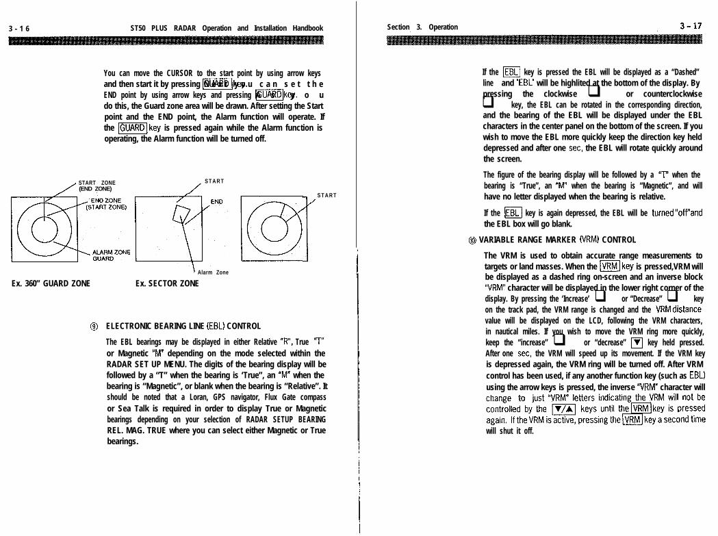
You can move the CURSOR to the start point by using arrow keysand then start it by pressing [-Ikey.N e x t y o u c a n s e t t h eEND point by using arrow keys and pressing mlkey.A s y o udo this, the Guard zone area will be drawn. After setting the Startpoint and the END point, the Alarm function will operate. Ifthe -[key is pressed again while the Alarm function isoperating, the Alarm function will be turned off.
START ZONE S T A R T/ (END ZONE) /
\ Alarm Zone
Ex. 360” GUARD ZONE Ex. SECTOR ZONE
S T A R T/
I@ ELECTRONIC BEARING LINE (EBL) CONTROL
The EBL bearings may be displayed in either Relative “R”, True ‘7”or Magnetic “M” depending on the mode selected within theRADAR SET UP MENU. The digits of the bearing display will befollowed by a “T” when the bearing is ‘True”, an “M” when thebearing is “Magnetic”, or blank when the bearing is “Relative”. Itshould be noted that a Loran, GPS navigator, Flux Gate compassor Sea Talk is required in order to display True or Magneticbearings depending on your selection of RADAR SETUP BEARINGREL. MAG. TRUE where you can select either Magnetic or Truebearings.
Section 3. Operation
If the m key is pressed the EBL will be displayed as a “Dashed”line and ‘EBL’ will be highlited at the bottom of the display. Bypressing the clockwise q or counterclockwiseq key, the EBL can be rotated in the corresponding direction,and the bearing of the EBL will be displayed under the EBLcharacters in the center panel on the bottom of the screen. If youwish to move the EBL more quickly keep the direction key helddepressed and after one set, the EBL will rotate quickly aroundthe screen.
The figure of the bearing display will be followed by a “T” when thebearing is “True”, an “M” when the bearing is “Magnetic”, and willhave no letter displayed when the bearing is relative.
If the m key is again depressed, the EBL will be turned“off”andthe EBL box will go blank.
@ VARIABLE RANGE MARKER (VRM) CONTROL
The VRM is used to obtain accurate range measurements totargets or land masses. When the mkey is pressed,VRM willbe displayed as a dashed ring on-screen and an inverse block“VRM” character will be displayed in the lower right corner of thedisplay. By pressing the ‘Increase’ q or “Decrease” q keyon the track pad, the VRM range is changed and the VRMdistancevalue will be displayed on the LCD, following the VRM characters,in nautical miles. If you wish to move the VRM ring more quickly,keep the “increase” q or “decrease” 111 key held pressed.After one set, the VRM will speed up its movement. If the VRM keyis depressed again, the VRM ring will be turned off. After VRMcontrol has been used, if any another function key (such as EBL)using the arrow keys is pressed, the inverse “VRM” character will
will shut it off.

3- 18 ST50 PLUS RADAR Operation and Installation Handbook
@ CURSOR CONTROLS
The Cursor feature combines the EBL and VRM functions and canbe used to quickly determine the range and bearings from yourown ship to any point on the radar screen. The cursor appears onthe display as a large (+I character.
To turn ON the Cursor mode, just press the -1 key. Ablocked word “CURSOR” appears at the bottom left side to let youknow that you are in the “Cursor” mode. The cursor (+I may nowbe positioned by using the arrow keys. The cursor can be moveddiagonally by pressing the w] keys simultaneously, or theIr/)keysI tsimu aneously. When the cursor is set to a positionon the screen, the range and bearing, will be displayed in thecursor window.
The bearing type of the cursor position will be the same as thatof the EBL as noted by the blank for Relative, ‘7” True or “M”Magnetic next to the cursor bearing.
To turn off the cursor, press the (CURSOR/ key again. The cursorinformation will be replaced by position information.
@ CTR/ZOOM KEY
The Off Center Mode lets you re-position the radar picture centerat any other point on the display so you can have a greater viewin the direction of interest.
When the-/key is pressed, the position of own ship canbe set anywhere on the screen up to 66% of the radius.
Press theICTR/ZOOMIkey. Both the cursor and the message “UseA./V/~/, to set sweep origin or press CTR/ZOOM for zoom”appears in the lower center portion of the display. Use directionkeys to set cursor for sweep origin (start point) then press-[key again to offset the picture. The Off Center Originis set using the arrow keys. To use the Off- Center feature set thecursor with arrow keys to the desired location for the Off Centersweep origin. Press the lCTR/ZOOM) key to activate the offsetmode and place own ship to the designed cursor location. Theorigin of the radar sweep will now shift to the cursor point. To turnoff Off Center and recenter the sweep, press the1 CTK/LUUM IKey
again.
Section 3. Operation
The Off Center Mode does not operate on the 16 nm range andcannot be used together with the ZOOM mode.
Since off centering cannot be used on the maximum range scale,if the range scale is increased to 16 NM, the origin of own ship willautomatically “cancel” the OFF Center mode and recenter ownship. If the radar system is turned OFF while off center mode is on,at next power up the offset mode will still be on.
No O f f s e t(.rljt a ‘,The Zoom mode can be used to magnify any designated area ofthe display by “two times”. When thelCTR/ZOOM]key is pressedtwice quickly, “X2” will be displayed on the top left of the screen.The area between own ‘ship and the designated location can bemagnified by a factor of 2 times by using the cursor as thecentering point. The zoom location can be set any where on thescreen up to 66% of the radius by usingthe arrow keys. Once you have set the cursor, press the[CTR/ZOOMkey to turn “ON” Zoom mode. To assist you inmaintaining proper range determination, the fixed range rings arealso turned “on” automatically.
Zoom mode can provide a quick means of getting a closer lookat a channel entrance, for example, but for navigation purposesit is recommended that you choose the next lower range scale anduse the Off Center feature for the same effect. By pressing the--__. ~~
ICTR/ZOOM) key again, the function can be turneb “off”. zoomdoes not operate on the l/8 nm range and cannot be usedtogether with “OFF CENTER”.
. __ . .-. _.. ._ .._. -- _-_.- .___._ -- - _._. -_ -_-. ‘.- __c______.” -___... . . _
ST50 PLUS RADAR Operation and Installation Handbook
0 CONT/DIM KEY
This CONT/DIM key is used to adjust the contrast of LCD or thebacklight brilliance of LCD and key pad.
The ICONT/DIMlkey turns the contrast and dimmer control mode“ON”. The message prompt appears “Use A/V for contrastUse d/ b-for Back light”. Set the contrast by using Ikeysand the dimmer level by using 4 /, , keys. The condition isset by pressing the CONT/DIM 1 key again.
You can control the contrast in 64 steps and the dimmer in 10steps.
@ MENU KEY
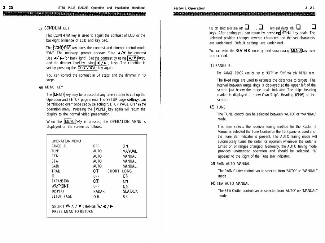
The pl key may be pressed at any time in order to call up theOperation and SETUP page menu. The SETUP page settinas canbe “skipped over” once set by selecting “SETUP PAGE 0FF”in theoperation menu. Pressing the lm[ key again will return thedisplay to the normal video presentation.
When the mkey is pressed, the OPERATION MENU isdisplayed on the screen as follows.
OPERATION MENURANGE R.TUNERAINS E AGAINTRAILI REXPANSIONWAYPOINTDISPLAYSETUP PAGE
OFFAUTO ENUALAUTO MANUALAUTO MANUALAUTO MANUALOFF SHORT LONGOFF QBOAOFF iiRADAR SEATALKO R ON
SELECT W/ A / V CHANGE W/ 4 / bPRESS MENU TO RETURN
.
Section 3. Operation 3 - 2 1
You can select each item with q , q keys and change with q , qkeys. After setting you can return by pressing[m]key again. Theselected position changes reverse character and the set charactersare underlined. Default settings are underlined.
You can enter the SEATALK mode by held depressingllkey overone srcond.
(1) RANGE R.
The RANGE RINGS can be set to “OFF” or “ON” via this MENU item.
The fixed rings are used to estimate the distances to targets. Theinterval between range rings is displayed at the upper left of thescreen just below the range scale indicator. The ships headingmarker is displayed to show Own Ship’s Heading (SHM) on thescreen.
(2) TUNE
The TUNE control can be selected between “AUTO” or “MANUAL”m o d e .
This item selects the receiver tuning method for the Radar. IfManual is selected the Tune Control on the front panel is used andthe Tune Bar indicator is present. The AUTO tuning mode willautomatically tune the radar for optimum whenever the radar isturned on or ranges changed. Generally, the AUTO tuning modeprovides unattended operation and should be selected. “A’appears to the Right of the Tune Bar indicator.
(3) RAIN AUTO MANUAL
The RAIN Clutter control can be selected from “AUTO” or “MANUAL”m o d e .
(4) SEA AUTO MANUAL
The SEA Clutter control can be selected from “AUTO” or “MANUAL”m o d e .

ST50 PLUS RADAR Operation and Installation Handbook
(5) GAIN
The GAIN control can be selected between “AUTO” or “MANUAL”m o d e .
This item selects the receiver gain sensitivity method for theRadar. If Manual is selected the GAIN Control on the front panelis used and the GAIN Bar indicator reacts to front panel changes.The AUTO gain mode will automatically adjust the radar foroptimum sensitivity whenever the radar is turned on or rangeschanged. Generally, the AUTO gain mode provides unattendedoperation and should be selected. “A” appears to the right of theGAIN Bar indicator.
(6) TRAIL
The TRAIL is displayed on the moving target in the TRAIL mode,and SHORT TRAIL, LONG TRAIL or TRAIL OFF can be selected.
This feature allows the operator to see the past history of targetmovement as an after-glow or “TRAIL” behind the moving targets.The OFF selection inhibits this function. The “SHORT” enables“TRAILS”, placing a short after-glow behind the moving targets.The “LONG” enables “TRAILS” with a longer after-glow.
If range scales are changed, the trails are cleared and new trailhistories must be redrawn to the screen.
The trails are drawn for anything that moves on the screen,including sea gulls, sea clutter, buoys, lobster pots, and shoreline.In general it is better to use the trail feature away from harbors andthe shoreline to avoid a cluttered display and concentrate on trailsof target vessels.
(7) IR
IR (Interference Rejection) mode can be set to “OFF” or “ON”. TheIR reduces noise on the display caused by other radars operatingnearby in the same frequency band. This function is also effectivein reducing some background noise. When active, the “IR”characters are displayed in upper window on the screen.
Section 3. Operation 3 - 2 3
If you are navigating in a port area serviced by a “RACON” beacon,you should turn off the IR mode to see the RACON signals.
(8) EXPANSION
Target Expand mode can be set to “OFF” or “ON”.The target expand mode allows the operator the ability to makesmall targets appear larger on the display for better viewing.When active, “EXP” characters are displayed in the upper leftwindow on the screen. This function enlarges all targets so useof expansion mode might want to be limited to only certainoccasions on the display.
(9) WAYPOINT
The WAYPOINT mode can be set to “OFF” or “ON”.When active and the radar is connected to a NAVAID with thenecessary data output, a waypoint symbol at the bearing andrange to the selected waypoint can be presented on the radardisplay. Numeric data, showing bearing, range and time totarget, appears with “WPT” characters in the upper right side ofthe screen. If the way point is not within the selected range scaleof the radar, only the dashed line indicating the bearing to thewaypoint can be displayed. When waypoint appears on the rangescale in use, the waypoint is displayed as a 0 with the center township) and the waypoint interconnected by a dotted line.
Should data be lost from a heading sensor or NAVAID, thewaypoint mode will disable and the message “NO DATA” willappear on the display.
The waypoint mode cannot be used if there is no course data froma NAVAID or magnetic sensor.
When using the waypoint mode on higher speed vessels thewaypoint symbol will tend to lag behind the actual waypoint. Oftenthis condition is due to lag in getting data from NAVAID and is morenoticeable on the shorter range scales.
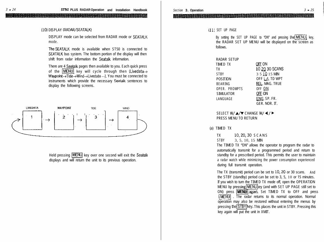
3 - 2 4 ST50 PLUS RADAR Operation and Installation Handbook
,101 DISPLAY (RADAR/SEATALK)
DISPLAY mode can be selected from RADAR rnode or SEATALKm o d e .
TheSEATALK mode is available when ST50 is connected toSEATALK bus system. The bottom portion of the display will thenshift from radar information the Seatalk information.
There are 4 Seatalk pages then available to you. Each quick pressof the [ml key wil l cycle through then (Livedata-+Waypoint-+Tide+Wind-+Livedata .-I. You must be connected toinstruments which provide the necessary Seatalk sentences todisplay the following screens.
LIVEDATA WAYPOINT TIDE
l - - - - l I - - - -
WIND
Held pressing [mq key over one second will exit the Seatalkdisplays and will return the unit to its previous operation.
Section 3. Operation 3 - 2 5
(11 ) SET UP PAGE
By setting the SET UP PAGE to “ON” and pressing them] key,the RADAR SET UP MENU will be displayed on the screen asfollows.
RADAR SETUPTIMED TXTXSTBYPOSITIONBEARINGOPER. PROMPTSSIMULATORLANGUAGE
EON102Q30SCANS3 5 lJ.j 15 MINOFF !JL TD WPTeEl;. MAG. TRUEOFF Q&lORONENG. SP. FR.GER. NOR. IT.
SELECT W/ A/V CHANGE W/ 4 / bPRESS MENU TO RETURN
(a) TIMED TX
TX 10,20,30 S C A N SSTBY 3, 5, 10, 15 MINThe TIMED TX “ON” allows the operator to program the radar toautomatically transmit for a programmed period and return tostandby for a prescribed period. This permits the user to maintaina radar watch while minimizing the power consumption experiencedduring full transmit operation.
The TX (transmit) period can be set to lo,20 or 30 scans. Andthe STBY (standby) period can be set to 3, 5, 10 or 15 minutes.If you wish to turn the TIMED TX mode off, open the OPERATIONMENU by pressing MENU key (and with SET UP PAGE still set to
iT?ON) press MENU again. Set TIMED TX to OFF and press\MENUI . The radar returns to its normal operation. Normal
operation may also be restored without entering the menus bypressing the(STBYlkey. This places the unit in STBY. Pressing thiskey again will put the unit in XMIT.

3 - 26 ST50 PLUS RADAR Operation and Installation Handbook
fb) POSITION
The POSITION display can be selected from present position L/L (Latitude/Longitude), TD (Time Differencel,WPT(way point Lat/Long) or OFF. L/L or TO data can only be displayed if you areconnected properly to a Loran C or GPS Receiver with proper dataoutput, or to Seatalk. This information appears at the lower leftcorner of the display.
(c) BEARING
When connected to a navigator such as a Loran-C or GPS, thisradar has three bearing modes available. They are “Relative”,“Magnetic” and “True”.
The “Relative” mode allows the operator to determine bearing toobjects displayed on the radar screen relative to own ship’sheading. These bearings are taken by utilizing the EBL or thecursor. All of the bearing data acquired in the relative mode isreferenced to the “SHM” (Ships Heading Marker).
When planning to plot information from the radar display to achart, it will be helpful to have the bearing information readoutsbe in degrees True or Magnetic. This bearing data may beobtained directly from the radar by selecting “MAGNETIC” or“TRUE”. The “MAGNETIC” and “TRUE” modes all depend onhaving a NAVAID or a magnetic flux sensor with proper dataformat connected to the radar system. In “MAGNETIC” mode,EBL, CURSOR and course bearings are indicated in magneticbearing as determined by the NAVAID input or optional magneticflux sensor input. The character “M” will be displayed to the rightof the EBL and Cursor characters to indicate the type of bearinginput. In “TRUE” mode, EBL, CURSOR and course bearings areindicated in True bearing as determined by the NAVAID input (i.e.no magnetic variation).
The character “T” will be displayed to the right of the EBL andCursor characters to indicate the type of bearing input.
Magnetic bearing data is the best when inputted from the optionalmagnetic flux sensor.
i
Section 3. Operation 3 - 2 7
(d) OPER. PROMPTS
The OPERATION PROMPTS can be displayed by setting this MENUitem to “ON”, and can be turned off by setting to “OFF”. TheOPERATION PROMPTS are helpful for radar operation, and aregenerally recommended to REMAIN ON.
(e) SIMULATOR
The SIMULATOR mode enables a sample radar picture on thedisplay when set to “ON”. This mode is used to practice becomingfamiliar with the various features and modes of the-display unit.
When active, the word “SIMULATION” is displayed at the top of theLCD screen.
The SIMULATOR mode is shut off by setting the MENU item to‘OFF’.
/f) LANGUAGE
The radar menus can be displayed in one of 6 LANGUAGES. Theyare English, Spanish, French, German, Norwegian and Italian.
After selecting any language, MENU and OPERATION PROMTS willchange to the selected language. A master reset will default theunit back to English.

Section 3. Operation
vtohelm
n
< >
(=I
”
RADAR\\ 1
II I /
I I