Embed Size (px)
Citation preview
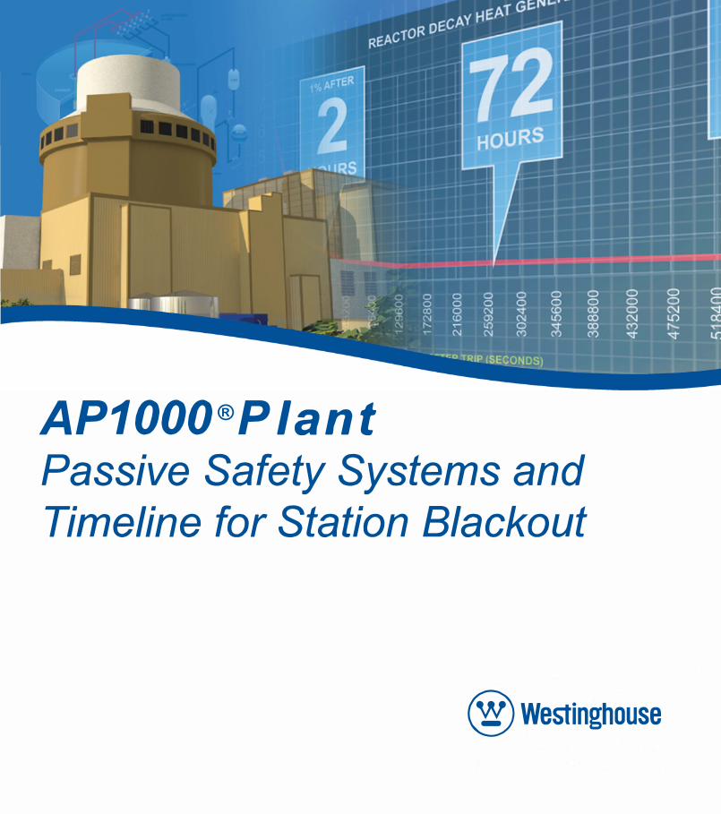
AP1000®PlantPassive Safety Systems and
Timeline for Station Blackout
@ Westinghouse
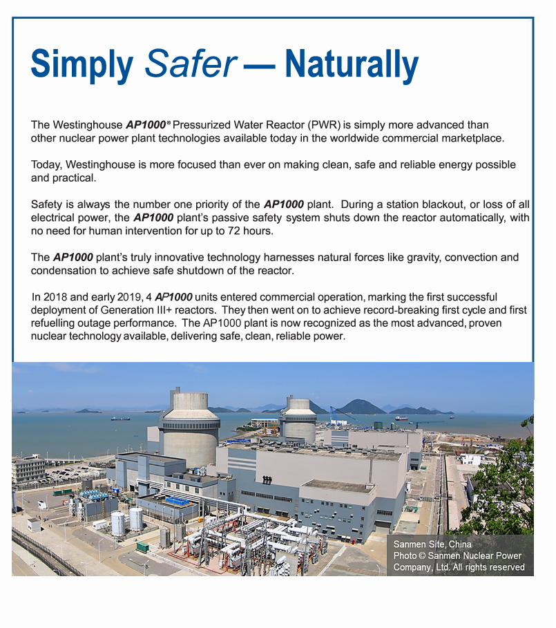
Simply Safer- Naturally
The Westinghouse AP1000® Pressurized Water Reactor (PWR) is simply more advanced than
other nuclear power plant technologies available today in the worldwide commercial marketplace.
Today, Westinghouse is more focused than ever on making clean, safe and reliable energy possible
and practical.
Safety is always the number one priority of the AP1000 plant. During a station blackout, or loss of all
electrical power, the AP1000 plant's passive safety system shuts down the reactor automatically, with
no need for human intervention for up to 72 hours.
The AP1000 plant's truly innovative technology harnesses natural forces like gravity, convection and
condensation to achieve safe shutdown of the reactor.
In 2018 and early 2019, 4 AP1000 units entered commercial operation, marking the first successfuldeployment of Generation III+ reactors. They then went on to achieve record-breaking first cycle and firstrefuelling outage performance. The AP1000 plant is now recognized as the most advanced, provennuclear technology available, delivering safe, clean, reliable power.
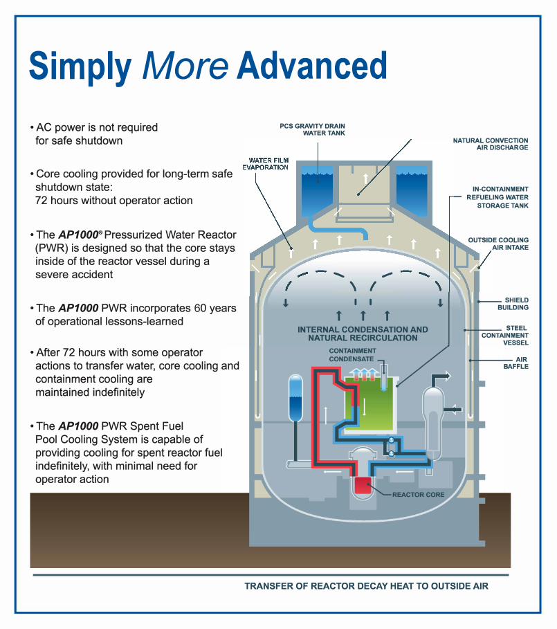
Simply More Advanced
• AC power is not required
for safe shutdown
• Core cooling provided for long-term safe
shutdown state:
72 hours without operator action
• The AP1000® Pressurized Water Reactor
(PWR) is designed so that the core stays
inside of the reactor vessel during a
severe accident
• The AP1000 PWR incorporates 60 years
of operational lessons-learned
• After 72 hours with some operator
actions to transfer water, core cooling and
containment cooling are
maintained indefinitely
• The AP1000 PWR Spent Fuel
Pool Cooling System is capable of
providing cooling for spent reactor fuel
indefinitely, with minimal need for
operator action
PCS GRAVITY DRAIN
WATER TANK
......
.a,
t
\
I
,-
I
I
t t INTERNAL CONDENSATION AND
NATURAL RECIRCULATION
.a,
NATURAL CONVECTION
AIR DISCHARGE
IN-CONTAINMENT
REFUELING WATER
STORAGE TANK
OUTSIDE COOLING
AIR INTAKE
SHIELD
BUILDING
STEEL
CONTAINMENT
VESSEL
AIR
BAFFLE
TRANSFER OF REACTOR DECAY HEAT TO OUTSIDE AIR
m
-
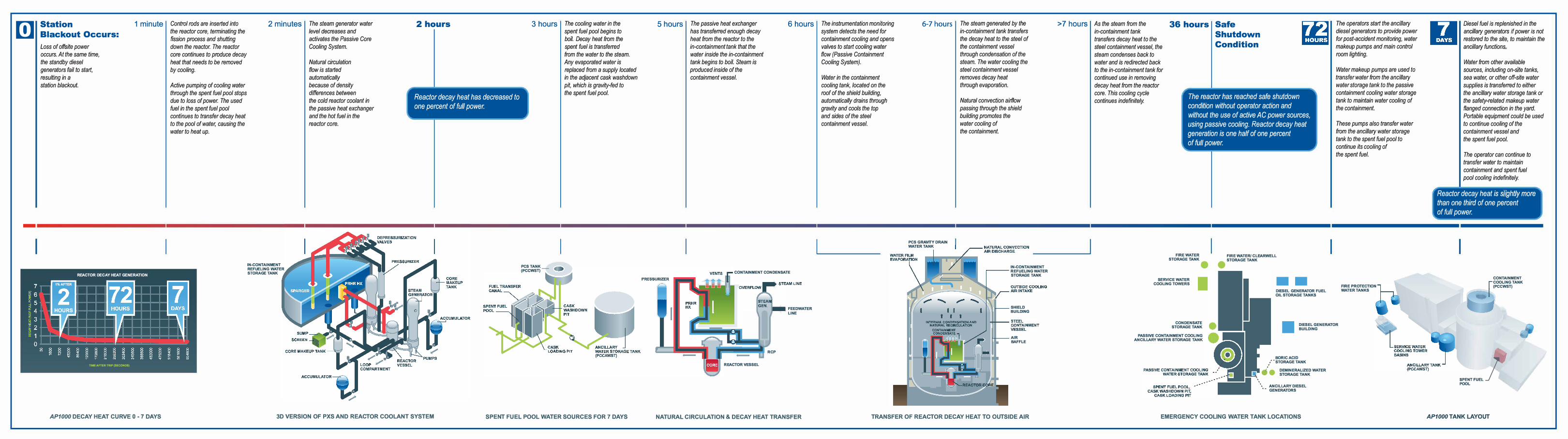
Station
Blackout Occurs:
Loss of offsite power occurs. At the same time, the standby diesel generators fail to start,
resulting in astation blackout.
1 minute
REACTOR DECAY HEAT GENERATION
1%AFTER
HOURS
TIME AFTER m.JP (SECONDS}
AP1000 DECAY HEAT CURVE O • 7 DAYS
Control rods are inserted into the reactor core, terminating the fission process and shutting down the reactor. The reactor core continues to produce decay heat that needs to be removed by cooling.
Active pumping of cooling water through the spent fuel pool stops due to loss of power. The used fuel in the spent fuel pool continues to transfer decay heat to the pool of water, causing the water to heat up.
2 minutes
IN-CONTAINMENT REFUELING WATER STORAGE TANK
The steam generator water level decreases and activates the Passive Core Cooling System.
Natural circulation flow is started automatically because of density differences between the cold reactor coolant in the passive heat exchanger and the hot fuel in the reactor core.
2 hours
Reactor decay heat has decreased to one percent of full power.
3 hours
PCS TANK (Pccwsn-
The cooling water in the spent fuel pool begins to boil. Decay heat from the spent fuel is transferred from the water to the steam. Any evaporated water isreplaced from a supply located in the adjacent cask washdown pit, which is gravity-fed to the spent fuel pool.
3D VERSION OF PXS AND REACTOR COOLANT SYSTEM SPENT FUEL POOL WATER SOURCES FOR 7 DAYS
5 hours The passive heat exchanger has transferred enough decay heat from the reactor to the in-containment tank that the water inside the in-containment tank begins to boil. Steam isproduced inside of the containment vessel.
6 hours
CONTAINMENT CONDENSATE
-REACTOR VESSEL
RCP
FEEDWATER LINE
NATURAL CIRCULATION & DECAY HEAT TRANSFER
The instrumentation monitoring system detects the need for containment cooling and opens valves to start cooling water flow (Passive Containment Cooling System).
Water in the containment cooling tank, located on the roof of the shield building, automatically drains through gravity and cools the top and sides of the steel containment vessel.
6-7 hours
PCS GRAVITY DRAIN WATER TANK
The steam generated by the in-containment tank transfers the decay heat to the steel of the containment vessel through condensation of the steam. The water cooling the steel containment vessel removes decay heat through evaporation.
Natural convection airflow passing through the shield building promotes the water cooling of the containment.
IN-CONTAINMENT �-- REFUELING WATER
STORAGE TANK
SHIEL□
BUILDING
AIR BAFFLE
TRANSFER OF REACTOR DECAY HEAT TO OUTSIDE AIR
> 7 hours As the steam from thein-containment tank transfers decay heat to the steel containment vessel, the steam condenses back to water and is redirected back to the in-containment tank for continued use in removing decay heat from the reactor core. This cooling cycle continues indefinitely.
36 hours Safe
Shutdown
Condition
The reactor has reached safe shutdown condition without operator action and without the use of active AC power sources, using passive cooling. Reactor decay heat generation is one half of one percent of full power.
FIRE WATER STORAGE TANK
FIRE WATER/ CLEARWELL
• STORAGE TANK
SERVICE WATER
I COOLING TOWERS •• DIESEL GENERATOR FUEL OIL STORAGE TANKS
The operators start the ancillary diesel generators to provide power for post-accident monitoring, water makeup pumps and main control room lighting,
Water makeup pumps are used to transfer water from the ancillary water storage tank to the passive containment cooling water storage tank to maintain water cooling of the containment.
These pumps also transfer water from the ancillary water storage tank to the spent fuel pool to continue its cooling of the spent fuel.
FIRE PROTECTION WATER TANKS
CONDENSATE STORAGE TANK ■
DIESEL GENERATOR BUILDING
PASSIVE CONTAINMENT COOLING ANCILLARY WATER STORAGE TANK
.
.
BORIC ACI□,' "STORAGE TANK ,
.
,n� • □EMINERALIZED WATER V STORAGE TANK
'. ANCILLARY DIESEL • - GENERATORS
EMERGENCY COOLING WATER TANK LOCATIONS
Diesel fuel is replenished in the ancillary generators if power is not restored to the site, to maintain the ancillary functions.
Water from other available sources, including on-site tanks, sea water, or other off-site water supplies is transferred to either the ancillary water storage tank or the safety-related makeup water flanged connection in the yard. Portable equipment could be used to continue cooling of the containment vessel and the spent fuel pool.
The operator can continue to transfer water to maintain containment and spent fuel pool cooling indefinitely
-------------
1 Reactor decay heat is slight/ y more
1 than one third of one percent of fut I power.
CONTAINMENT r COOLING TANK
I (PCCWST)
'"'"' '"" j POOL
AP1000 TANK LAYOUT

SIMPLY ELECTRIC™
lm,rl
Follow
us on:
www.westinghousenuclear.com
AP1000 and the AP1000 logo are trademarks or registered trademarks of Westinghouse Electric Company LLC, its subsidiaries and/or its affiliates in the United States.
These marks may also be used and/or registered in other countries throughout the world. All rights reserved. Unauthorized use is strictly prohibited.
© 2021 Westinghouse Electric Company LLC. All rights reserved.
Westinghouse Graphic Services & Identity: 88473A_rev0_ 10/11_ 10M