Embed Size (px)
Citation preview
Siemens Energy & Automation, Inc. INSTALLATION AND SERVICE INSTRUCTION
SD39SAI-1 Rev: 4 September 2005
APACS+™
Standard Analog Input (SAI) Module
Trademarks ProcessSuite, QUADLOG, 4-mation, and APACS+ are trademarks of Siemens Energy & Automation, Inc.
Other names in this publication might be trademarks, the use of which by third parties for their own purposes may violate the rights of the registered holder.
Copyright Siemens Energy & Automation, Inc. 2005 All rights reserved
The reproduction, transmission or use of this document or its contents is not permitted without express written authority. Offenders will be liable for damages. All rights, including rights created by patent or registration of a utility model or design, are reserved. Siemens Energy & Automation, Inc. 1201 Sumneytown Pike P.O. Box 900 Spring House, PA 19477-0900
Disclaimer of Liability We have checked the contents of this manual for agreement with the hardware and software described. Since deviations cannot be precluded entirely, we cannot guarantee full agreement. However, the data in this manual is reviewed regularly and any necessary corrections included in subsequent editions. Suggestions for improvement are welcomed. ©Siemens Energy & Automation, Inc. 2005 Technical data subject to change.
SD39SAI-1 Contents
September 2005 i
Table of Contents
Section Title Page
1 Introduction....................................................................................................................1-1 1.1 Product Description ......................................................................................................1-1 1.2 Product Support ............................................................................................................1-3 1.3 Related Literature .........................................................................................................1-5
2 Installation......................................................................................................................2-1 2.1 Hardware Identification................................................................................................2-1 2.1.1 Module Identification.............................................................................................2-1 2.1.2 Marshalled Termination Assembly Identification..................................................2-2 2.2 Preparations ..................................................................................................................2-2 2.3 Environmental Considerations .....................................................................................2-3 2.4 Equipment Delivery and Handling ...............................................................................2-3 2.4.1 Predelivery Test .....................................................................................................2-3 2.4.2 Factory Shipment ...................................................................................................2-3 2.4.3 Receipt of Shipment...............................................................................................2-3 2.4.4 Return of Equipment within North America..........................................................2-4 2.4.5 Return of Equipment outside North America ........................................................2-4 2.4.6 Equipment Handling and Storage ..........................................................................2-4 2.5 Marshalled Termination Assembly and Cable Installation...........................................2-4 2.5.1 Marshalled Termination Assembly Installation .....................................................2-5 2.5.2 Optional (Flat Surface) Marshalled Termination Assembly Installation .............2-10 2.5.3 Interconnect I/O Cable Installation ......................................................................2-11 2.6 SAI Installation...........................................................................................................2-13 2.6.1 Module Rack Mechanical Keying........................................................................2-15 2.6.2 Module Installation ..............................................................................................2-15 2.7 Electrical Installation..................................................................................................2-15 2.7.1 Field Wire Selection.............................................................................................2-16 2.7.2 Marshalled Termination Assembly – I/O Wiring Connections ...........................2-17 2.7.3 Unterminated I/O Cable Assembly Connections .................................................2-19 2.8 Configuration..............................................................................................................2-20
3 Maintenance ...................................................................................................................3-1 3.1 Requirements ................................................................................................................3-1 3.2 Visual Inspection ..........................................................................................................3-1 3.3 Cleaning........................................................................................................................3-2 3.4 Troubleshooting............................................................................................................3-2 3.5 SAI Removal/Replacement ..........................................................................................3-3 3.5.1 Removal .................................................................................................................3-3 3.5.2 Replacement...........................................................................................................3-4 3.6 Marshalled Termination Assembly Removal/Replacement .........................................3-4 3.6.1 Removal .................................................................................................................3-4 3.6.2 Replacement...........................................................................................................3-5 3.7 Interconnect I/O Cable Removal/Replacement ............................................................3-5 3.7.1 Removal .................................................................................................................3-5
Contents SD39SAI-1
ii September 2005
3.7.2 Replacement...........................................................................................................3-5 3.8 Spare and Replacement Parts........................................................................................3-6 3.9 Maintenance Records ...................................................................................................3-6
4 Circuit Description ........................................................................................................4-1 4.1 Isolated Power Supply ..................................................................................................4-1 4.2 IOBUS Modem.............................................................................................................4-1 4.3 Multiplexers/Converters ...............................................................................................4-2 4.4 CPU ..............................................................................................................................4-2
5 Model Designation .........................................................................................................5-1 5.1 Options .........................................................................................................................5-1 5.2 Accessories ...................................................................................................................5-2
6 Specifications..................................................................................................................6-1 6.1 Module Specifications ..................................................................................................6-1 6.2 Environmental Specifications.......................................................................................6-2 6.3 Electrical Classification................................................................................................6-4 6.3.1 Approvals ...............................................................................................................6-4 6.3.2 CSA Hazardous Locations Precautions .................................................................6-5
Index 9
List of Tables
Table Title Page
Table 2–1 Field Wire Selection ..............................................................................................................2-16
Table 2–2 Unterminated I/O Cable Assembly ........................................................................................2-21
Table 3–1 LED Indications .......................................................................................................................3-2
Table 5–1 SAI Options .............................................................................................................................5-1
Table 5–2 SAI Accessories .......................................................................................................................5-2
Table 6–1 SAI Specifications ...................................................................................................................6-1
Table 6–2 SAI Environmental Specifications...........................................................................................6-2
Table 6–3 Agency Approvals For SAI .....................................................................................................6-4
SD39SAI-1 Contents
September 2005 iii
List of Illustrations
Figure Title Page
Figure 1–1 Standard Analog Input (SAI) Module and Associated Hardware ..........................................1-2
Figure 2–1 SAI Identification Label ........................................................................................................2-1
Figure 2–2 Marshalling Utility Panel Dimensions ...................................................................................2-7
Figure 2–3 Standard SAI/CAI Marshalled Termination Assembly .........................................................2-8
Figure 2–4 Installing or Removing a Marshalled Termination Assembly................................................2-9
Figure 2–5 Marshalled Termination Assembly ⎯ Mounting Ear Installation .......................................2-10
Figure 2–6 Keying an Interconnect I/O Cable Assembly for SAI Use...................................................2-12
Figure 2–7 Module and Rack Keying .....................................................................................................2-14
Figure 2–8 SAI I/O Wiring Connections on Marshalled Resistor Termination Assembly.....................2-18
Figure 2–9 I/O Supply Monitor Line Connections .................................................................................2-19
Figure 4–1 SAI Block Diagram ................................................................................................................4-2
Figure 4–2 SAI Channel Circuit ...............................................................................................................4-3
Significant Changes for Revision 4
Section Description
PREFACE (Conventions and Symbols)— new section
1.2 Product Support—contact information updated.
2.7 Electrical Installation—DANGER alert added
3 Maintenance—DANGER alert added
6.3.2 CSA Hazardous Locations Precautions—WARNING alert added
Contents SD39SAI-1
iv September 2005
PREFACE
Conventions and Symbols
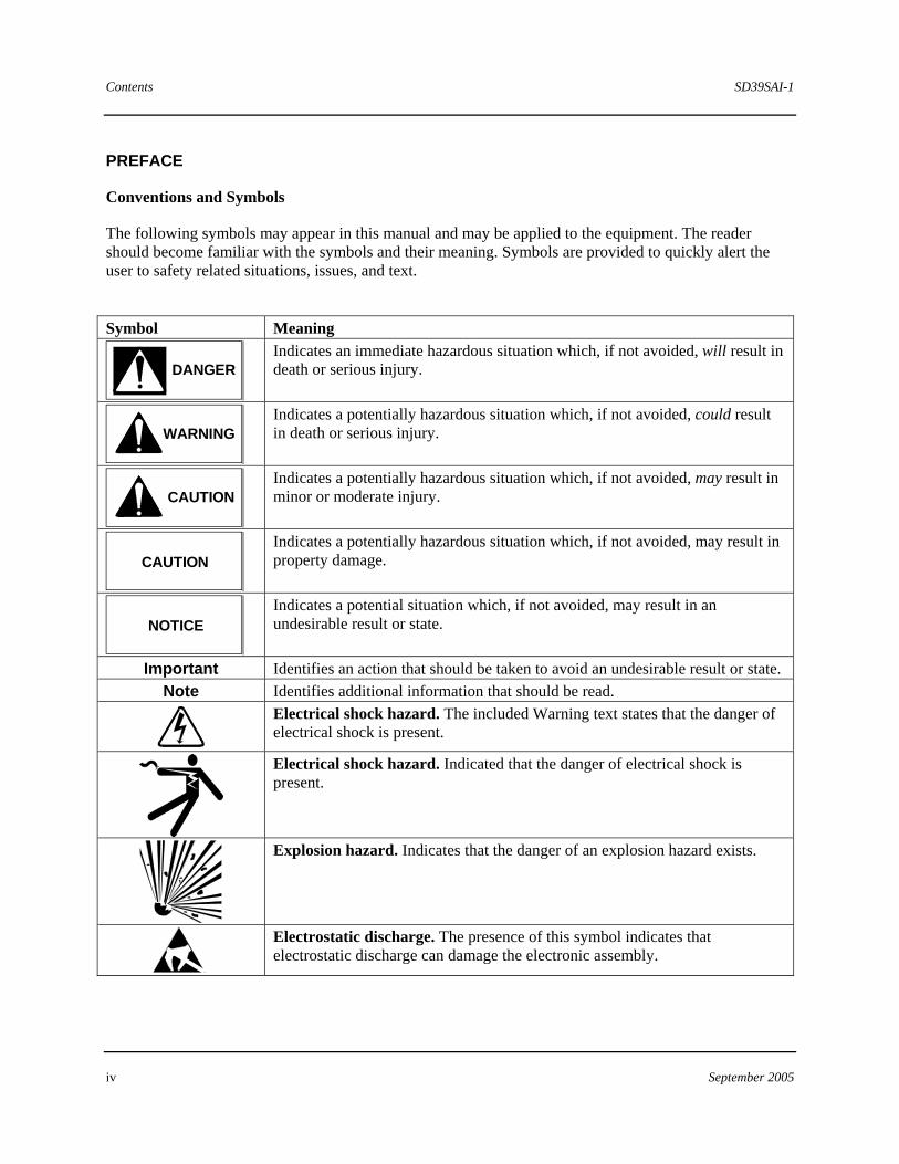
The following symbols may appear in this manual and may be applied to the equipment. The reader should become familiar with the symbols and their meaning. Symbols are provided to quickly alert the user to safety related situations, issues, and text.
Symbol Meaning
DANGER
Indicates an immediate hazardous situation which, if not avoided, will result in death or serious injury.
WARNING
Indicates a potentially hazardous situation which, if not avoided, could result in death or serious injury.
CAUTION
Indicates a potentially hazardous situation which, if not avoided, may result in minor or moderate injury.
CAUTION
Indicates a potentially hazardous situation which, if not avoided, may result in property damage.
NOTICE
Indicates a potential situation which, if not avoided, may result in an undesirable result or state.
Important Identifies an action that should be taken to avoid an undesirable result or state. Note Identifies additional information that should be read.
Electrical shock hazard. The included Warning text states that the danger of electrical shock is present.
Electrical shock hazard. Indicated that the danger of electrical shock is present.
Explosion hazard. Indicates that the danger of an explosion hazard exists.
Electrostatic discharge. The presence of this symbol indicates that electrostatic discharge can damage the electronic assembly.
SD39SAI-1 Contents
September 2005 v
Qualified Persons
The described equipment should be installed, configured, operated, and serviced only by qualified persons thoroughly familiar with this publication. The current version, in Portable Document Format (PDF), is available at 6http://sitescape.sea.siemens.com/.
For the purpose of this publication and product labels, a qualified person is one who is familiar with the installation, construction, and operation of the equipment, and the involved hazards. In addition, he or she has the following qualifications:
• Is trained and authorized to energize, de-energize, clear, ground and tag circuits and equipment in accordance with established safety practices.
• Is trained in the proper care and use of protective equipment such as rubber gloves, hard hat, safety glasses or face shields, flash clothing, etc., in accordance with established safety practices.
• Is trained in rendering first aid.
Scope
This publication does not purport to cover all details or variations in equipment, nor to provide for every possible contingency to be met in connection with installation, operation, or maintenance. Should further information be desired or should particular problems arise which are not covered sufficiently for the purchaser’s purposes, the matter should be referred to one of the support groups listed in the Product Support section of this manual.
The contents of this manual shall not become part of or modify any prior or existing agreement, commitment or relationship. The sales contract contains the entire obligation of Siemens. The warranty contained in the contract between the parties is the sole warranty of Siemens. Any statements continued herein do not create new warranties or modify the existing warranty.
General Warnings and Cautions
WARNING
This equipment contains hazardous voltages, and it has been certified for use in the hazardous locations specified on the product nameplate and in the Model Designation and Specifications section. Death, serious personal injury, or property damage can result if safety instructions are not followed. Only qualified personnel should work on or around this equipment after becoming thoroughly familiar with all warning, safety notices, and maintenance procedures contained herein. The successful and safe operation of this equipment is dependent upon proper handling, installation, operation, and maintenance.
The perfect and safe operation of the equipment is conditional upon proper transport, proper storage, installation and assembly, as well as, on careful operation and commissioning.
The equipment may be used only for the purposes specified in this publication.
Contents SD39SAI-1
vi September 2005
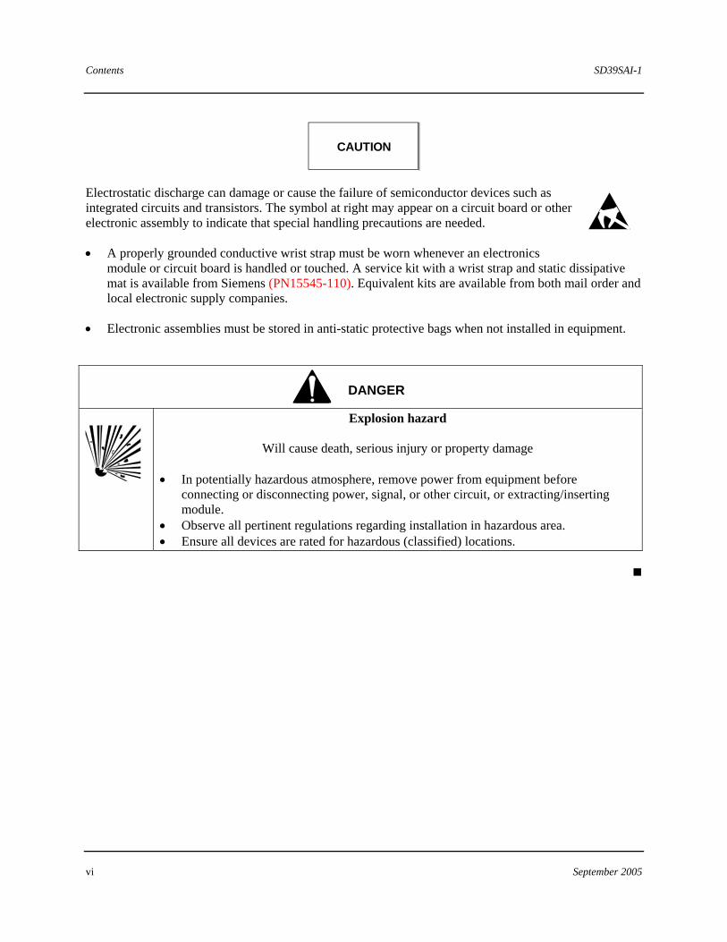
CAUTION
Electrostatic discharge can damage or cause the failure of semiconductor devices such as integrated circuits and transistors. The symbol at right may appear on a circuit board or other electronic assembly to indicate that special handling precautions are needed.
• A properly grounded conductive wrist strap must be worn whenever an electronics module or circuit board is handled or touched. A service kit with a wrist strap and static dissipative mat is available from Siemens (PN15545-110). Equivalent kits are available from both mail order and local electronic supply companies.
• Electronic assemblies must be stored in anti-static protective bags when not installed in equipment.
DANGER
Explosion hazard
Will cause death, serious injury or property damage • In potentially hazardous atmosphere, remove power from equipment before
connecting or disconnecting power, signal, or other circuit, or extracting/inserting module.
• Observe all pertinent regulations regarding installation in hazardous area. • Ensure all devices are rated for hazardous (classified) locations.
SD39SAI-1 Introduction
September 2005 1-1
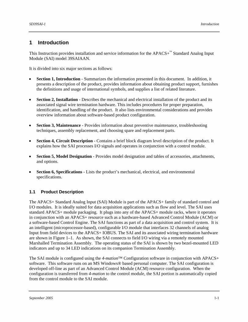
1 Introduction
This Instruction provides installation and service information for the APACS+™ Standard Analog Input Module (SAI) model 39SAIAAN.
It is divided into six major sections as follows:
• Section 1, Introduction - Summarizes the information presented in this document. In addition, it presents a description of the product, provides information about obtaining product support, furnishes the definitions and usage of international symbols, and supplies a list of related literature.
• Section 2, Installation - Describes the mechanical and electrical installation of the product and its associated signal wire termination hardware. This includes procedures for proper preparation, identification, and handling of the product. It also lists environmental considerations and provides overview information about software-based product configuration.
• Section 3, Maintenance - Provides information about preventive maintenance, troubleshooting techniques, assembly replacement, and choosing spare and replacement parts.
• Section 4, Circuit Description - Contains a brief block diagram level description of the product. It explains how the SAI processes I/O signals and operates in conjunction with a control module.
• Section 5, Model Designation - Provides model designation and tables of accessories, attachments, and options.
• Section 6, Specifications - Lists the product’s mechanical, electrical, and environmental specifications.
1.1 Product Description
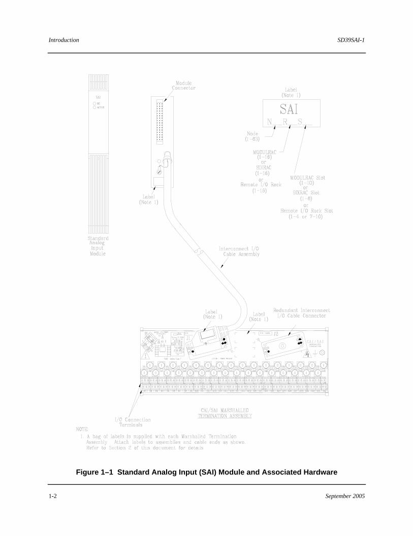
The APACS+ Standard Analog Input (SAI) Module is part of the APACS+ family of standard control and I/O modules. It is ideally suited for data acquisition applications such as flow and level. The SAI uses standard APACS+ module packaging. It plugs into any of the APACS+ module racks, where it operates in conjunction with an APACS+ resource such as a hardware-based Advanced Control Module (ACM) or a software-based Control Engine. The SAI functions as part of a data acquisition and control system. It is an intelligent (microprocessor-based), configurable I/O module that interfaces 32 channels of analog Input from field devices to the APACS+ IOBUS. The SAI and its associated wiring termination hardware are shown in Figure 1–1. As shown, the SAI connects to field I/O wiring via a remotely mounted Marshalled Termination Assembly. The operating status of the SAI is shown by two bezel-mounted LED indicators and up to 34 LED indications on its companion Termination Assembly.
The SAI module is configured using the 4-mation™ Configuration software in conjunction with APACS+ software. This software runs on an MS Windows® based personal computer. The SAI configuration is developed off-line as part of an Advanced Control Module (ACM) resource configuration. When the configuration is transferred from 4-mation to the control module, the SAI portion is automatically copied from the control module to the SAI module.
Introduction SD39SAI-1
1-2 September 2005
Figure 1–1 Standard Analog Input (SAI) Module and Associated Hardware
SD39SAI-1 Introduction
September 2005 1-3
1.2 Product Support
Our Technical Support Centers (TSC) offer a variety of technical support services that are designed to assist you with Siemens products and systems. Our support engineers have experience with troubleshooting, development, system startup, and system test. They will help you to solve your issues in an efficient and professional manner.
Customers in North America can contact Siemens Technical Support Center at 1-800-333-7421, on the web at: http://support.automation.siemens.com, or by e-mail: [email protected]
Customers outside North America can contact their local Siemens subsidiary; addresses and telephone numbers are listed on the Internet at the web site: http://support.automation.siemens.com.
When contacting Siemens, customers will be asked to provide site-contact information (name, address, and phone number), the product involved and detailed information regarding the nature of the issue.
Product documentation is now located in the Library forum of the Process Automation User Connection at: http://sitescape.sea.siemens.com/. The Process Automation User Connection is a secure site. Registration is open to all verified users of Siemens process automation systems. If you are not already, and would like to become a member, please visit our Process Automation User Connection web page at: http://www.sea.siemens.com/process/support/papauc.html
Contained within the Process Automation User Connection is the APACS+/QUADLOG Secure Site at: http://sitescape.sea.siemens.com/forum/aca-1/dispatch.cgi/f.apacsquadlo forum. This site is only open to customers with an active service agreement. It contains all service manuals, service memos, service notes, configuration manuals, etc. for the APACS+ and QUADLOG family of products. If you are experiencing technical difficulties with the site, please contact SiteScape technical support at: toll free 1-877-234-1122 (US) or 1-513-336-1474.
Introduction SD39SAI-1
1-4 September 2005
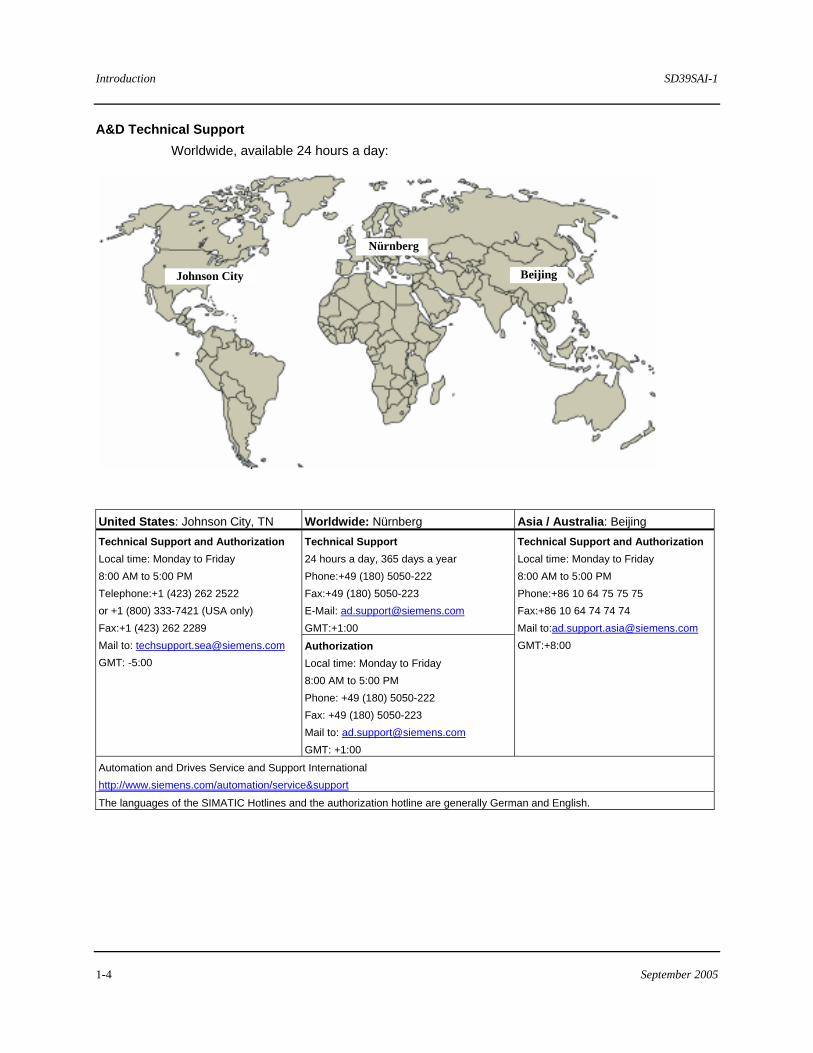
A&D Technical Support Worldwide, available 24 hours a day:
Beijing
Nürnberg
Johnson City
United States: Johnson City, TN Worldwide: Nürnberg Asia / Australia: Beijing Technical Support 24 hours a day, 365 days a year Phone:+49 (180) 5050-222 Fax:+49 (180) 5050-223 E-Mail: [email protected] GMT:+1:00
Technical Support and Authorization Local time: Monday to Friday 8:00 AM to 5:00 PM Telephone:+1 (423) 262 2522 or +1 (800) 333-7421 (USA only) Fax:+1 (423) 262 2289 Mail to: [email protected] GMT: -5:00
Authorization Local time: Monday to Friday 8:00 AM to 5:00 PM Phone: +49 (180) 5050-222 Fax: +49 (180) 5050-223 Mail to: [email protected] GMT: +1:00
Technical Support and Authorization Local time: Monday to Friday 8:00 AM to 5:00 PM Phone:+86 10 64 75 75 75 Fax:+86 10 64 74 74 74 Mail to:[email protected] GMT:+8:00
Automation and Drives Service and Support International http://www.siemens.com/automation/service&support
The languages of the SIMATIC Hotlines and the authorization hotline are generally German and English.
SD39SAI-1 Introduction
September 2005 1-5
1.3 Related Literature
The following documents are available to complement the installation, configuration, and maintenance of the SAI. Generally, all needed documentation is supplied with your equipment. It may be supplied in electronic form in the Adobe™ portable document format (PDF), printed form, or both. Refer to these documents as needed or as called for in text. Documents may be located on your workstation’s hard drive or on a CD supplied with your system.
• Using the 4-mation Configuration Software (document number CG39-20)
• APACS+ I/O Module Configuration (document number CG39-21)
• ACM/ACM+ Standard Function Blocks (document number CG39-22)
• MODULPAC 1000 Installation and Service Instruction (document number SD39MODULPAC-1)

SD39SAI-1 Installation
September 2005 2-1
2 Installation
This section describes installation of the Standard Analog Input (SAI) module and its associated I/O wiring termination hardware. Review and complete the preparatory steps in section 2.2 before proceeding with the installation.
IMPORTANT
The SAI installation should be in accordance with the National Electrical Code (NEC), other applicable construction, and electrical codes.
The SAI is only to be used for the purposes described by Siemens.
2.1 Hardware Identification
2.1.1 Module Identification
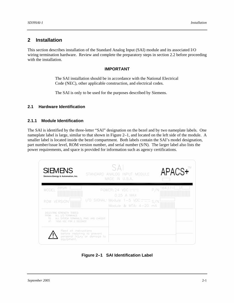
The SAI is identified by the three-letter “SAI” designation on the bezel and by two nameplate labels. One nameplate label is large, similar to that shown in Figure 2–1, and located on the left side of the module. A smaller label is located inside the bezel compartment. Both labels contain the SAI’s model designation, part number/issue level, ROM version number, and serial number (S/N). The larger label also lists the power requirements, and space is provided for information such as agency certifications.
Siemens Energy & Automation, Inc.
SIEMENS
Figure 2–1 SAI Identification Label
Installation SD39SAI-1
2-2 September 2005
2.1.2 Marshalled Termination Assembly Identification
The SAI is used with a companion SAI/CAI Marshalled Termination Assembly. This assembly is identified by the following information printed on its surface.
SAI/CAI
MARSHALLED TERMINATION
P/N 16428-1
2.2 Preparations
1. Install the MODULRAC (SIXRAC, or Remote I/O Rack) in the cabinet where the SAI is to be installed. The SAI should not be installed in the rack at this time; however, its designated slot number should be known.
2. If remote I/O termination is employed, complete the following tasks:
• If Marshalling Utility Panels are being used, install them in their respective marshalling cabinets.
• Tag all I/O cables and route them into the marshalling cabinet. They should be ready for cable end preparation and connection to the SAI/CAI Marshalled Termination Assemblies. Cable wire sizes: 24 to 12 AWG.
• Route the Interconnect I/O Cable (or Unterminated I/O Cable) between the rack in which the SAI is to be installed and the marshalling cabinet. Refer to Figure 1-1; the J1 end of the cable is to be installed in the rack and P2 end is to be connected to the appropriate Marshalled Termination Assembly in the marshalling cabinet.
• If an Unterminated I/O Cable is installed, you must supply and install the appropriate termination hardware (terminal blocks) for field signal I/O wiring and the I/O Cable.
3. If channel diagnostics are to be used for automatically detecting wiring faults such as short or open circuits, each channel must be wired with the appropriate resistors (and configured accordingly).
High-power EMI-producing equipment should not be connected to any power lines dedicated to SAI I/O signals.
SD39SAI-1 Installation
September 2005 2-3
2.3 Environmental Considerations
• Many industrial environments create severe operating conditions. The conditions at each SAI location must be within the specifications stated in section 6.2.
• To ensure operator safety, Marshalled Termination Assemblies shall be installed in enclosures, which require a key or special tool to gain access to the equipment.
• To ensure reliable data communications, it would be prudent to locate SAI hardware as far as possible from sources of interference, such as high current electrical equipment, which emits strong electromagnetic fields and switching transients.
2.4 Equipment Delivery and Handling
The following subsections provide information of interest to shipping, receiving, and warehouse personnel.
2.4.1 Predelivery Test
Each SAI is fully tested and inspected to ensure proper operation. If the module is ordered factory-installed in a MODULPAC or other enclosure, the module is tested as part of the system and inspected to ensure proper operation.
2.4.2 Factory Shipment
Each SAI is enclosed in a static shielding bag and packaged for shipment. Accessories are packaged separately. If a SAI is ordered factory-installed in a MODULPAC or other enclosure, the enclosure is bolted to a pallet and wrapped for protection during shipment.
2.4.3 Receipt of Shipment
All cartons should be inspected at the time of their delivery for possible external damage. Any visible damage should be immediately recorded on the carrier’s copy of the delivery slip.
Each carton should be carefully unpacked and its contents checked against the enclosed packing list. At the same time, each item should be inspected for hidden damage that may or may not have to be accompanied by exterior carton damage.
If it is found that some items have been damaged or are discovered missing, refer to sections 2.4.4 or 2.4.5 and notify Siemens immediately, providing full details. In addition, damages must be reported to the carrier with a request for their on-site inspection of the damaged item and its shipping carton.
Installation SD39SAI-1
2-4 September 2005
2.4.4 Return of Equipment within North America
US Customers:
• Call the Repair Order PAS Inside Sales/Order Management Group at (215) 646-7400, ext 4RMA (4762) weekdays between 8:00 a.m. and 4:45 p.m. eastern time to obtain an RMA number. Mark the RMA number prominently on the outside of the shipment.
• When calling for an RMA number, provide the reason for the return. If returning equipment for repair, a detailed description of failure symptoms and system behavior will be requested. Supply a purchase order number for repairs. Follow the TSC specialist's recommendation for battery connection, if applicable.
• If applicable, you must supply a Material Safety Data Sheet (MSDS) with each item being returned if it was stored or used in a location where hazardous materials were present.
• Package items to be returned in their original shipping containers. Otherwise, package it for safe shipment or contact the factory for shipping recommendations. A module must be placed inside a static shielding bag to protect it from electrostatic discharge.
Canadian customers:
Contact Siemens Canada.
2.4.5 Return of Equipment outside North America
Contact your Siemens Representative.
2.4.6 Equipment Handling and Storage
The SAI is completely enclosed and can be safely handled without undertaking special ESD (electrostatic discharge) handling procedures provided the bezel compartment door is closed and secured. DO NOT touch the connector pins on the back of the module. Handle the module carefully and do not subject it to excessive shock or vibration.
The storage temperature and humidity parameters listed in section 6 must be met for storage of a SAI.
2.5 Marshalled Termination Assembly and Cable Installation
Section 2.5.1 describes installing a Marshalled Termination Assembly to a DIN (Deutsches Industrie Norms) rail. Section 2.5.2 describes installing a Marshalled Termination Assembly to a flat surface. Section 2.5.3 describes connecting an Interconnect I/O Cable Assembly.
SD39SAI-1 Installation
September 2005 2-5
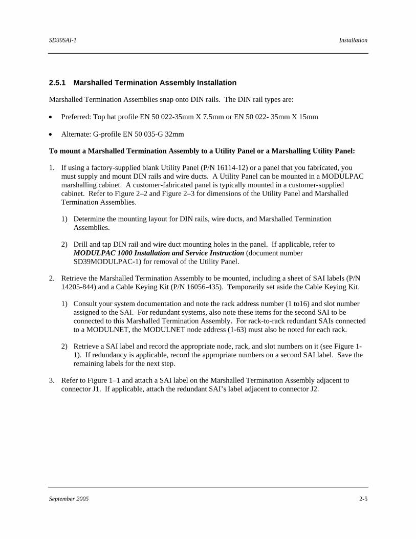
2.5.1 Marshalled Termination Assembly Installation
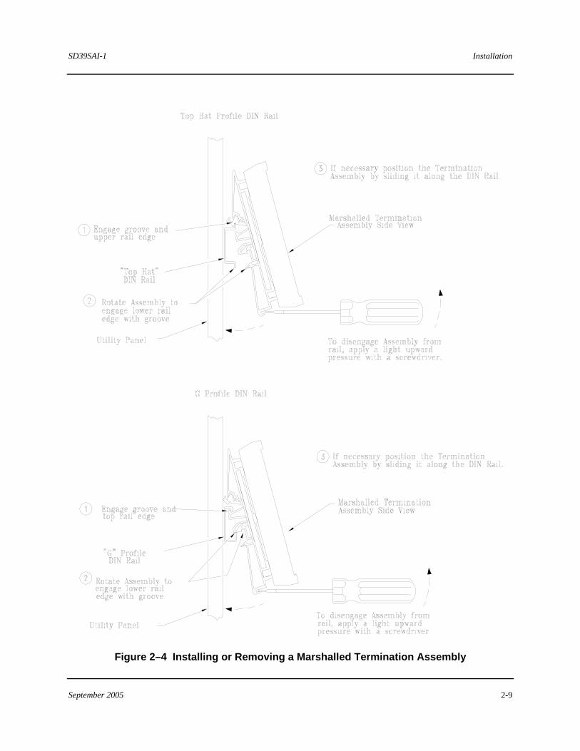
Marshalled Termination Assemblies snap onto DIN rails. The DIN rail types are:
• Preferred: Top hat profile EN 50 022-35mm X 7.5mm or EN 50 022- 35mm X 15mm
• Alternate: G-profile EN 50 035-G 32mm
To mount a Marshalled Termination Assembly to a Utility Panel or a Marshalling Utility Panel:
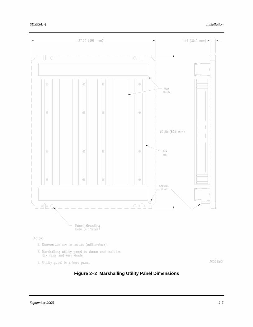
1. If using a factory-supplied blank Utility Panel (P/N 16114-12) or a panel that you fabricated, you must supply and mount DIN rails and wire ducts. A Utility Panel can be mounted in a MODULPAC marshalling cabinet. A customer-fabricated panel is typically mounted in a customer-supplied cabinet. Refer to Figure 2–2 and Figure 2–3 for dimensions of the Utility Panel and Marshalled Termination Assemblies.
1) Determine the mounting layout for DIN rails, wire ducts, and Marshalled Termination Assemblies.
2) Drill and tap DIN rail and wire duct mounting holes in the panel. If applicable, refer to MODULPAC 1000 Installation and Service Instruction (document number SD39MODULPAC-1) for removal of the Utility Panel.
2. Retrieve the Marshalled Termination Assembly to be mounted, including a sheet of SAI labels (P/N 14205-844) and a Cable Keying Kit (P/N 16056-435). Temporarily set aside the Cable Keying Kit.
1) Consult your system documentation and note the rack address number (1 to16) and slot number assigned to the SAI. For redundant systems, also note these items for the second SAI to be connected to this Marshalled Termination Assembly. For rack-to-rack redundant SAIs connected to a MODULNET, the MODULNET node address (1-63) must also be noted for each rack.
2) Retrieve a SAI label and record the appropriate node, rack, and slot numbers on it (see Figure 1-1). If redundancy is applicable, record the appropriate numbers on a second SAI label. Save the remaining labels for the next step.
3. Refer to Figure 1–1 and attach a SAI label on the Marshalled Termination Assembly adjacent to connector J1. If applicable, attach the redundant SAI’s label adjacent to connector J2.
Installation SD39SAI-1
2-6 September 2005
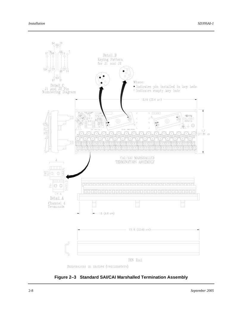
4. As a safety check, verify that connectors J1 and J2 are factory keyed according to Figure 2–3 and Figure 2–6.
NOTE
It is important to key the connector on the mating Interconnect I/O Cable as described in section 2.5.3. Keying is a safety feature for preventing the improper connection of an Interconnect I/O Cable from another type of I/O module to a SAI/CAI Marshalled Termination Assembly.
5. Refer to Figure 2–5 for the procedure to mount a Marshalled Termination Assembly to a DIN rail.
SD39SAI-1 Installation
September 2005 2-7
Figure 2–2 Marshalling Utility Panel Dimensions
Installation SD39SAI-1
2-8 September 2005
Figure 2–3 Standard SAI/CAI Marshalled Termination Assembly
SD39SAI-1 Installation
September 2005 2-9
Figure 2–4 Installing or Removing a Marshalled Termination Assembly
Installation SD39SAI-1
2-10 September 2005
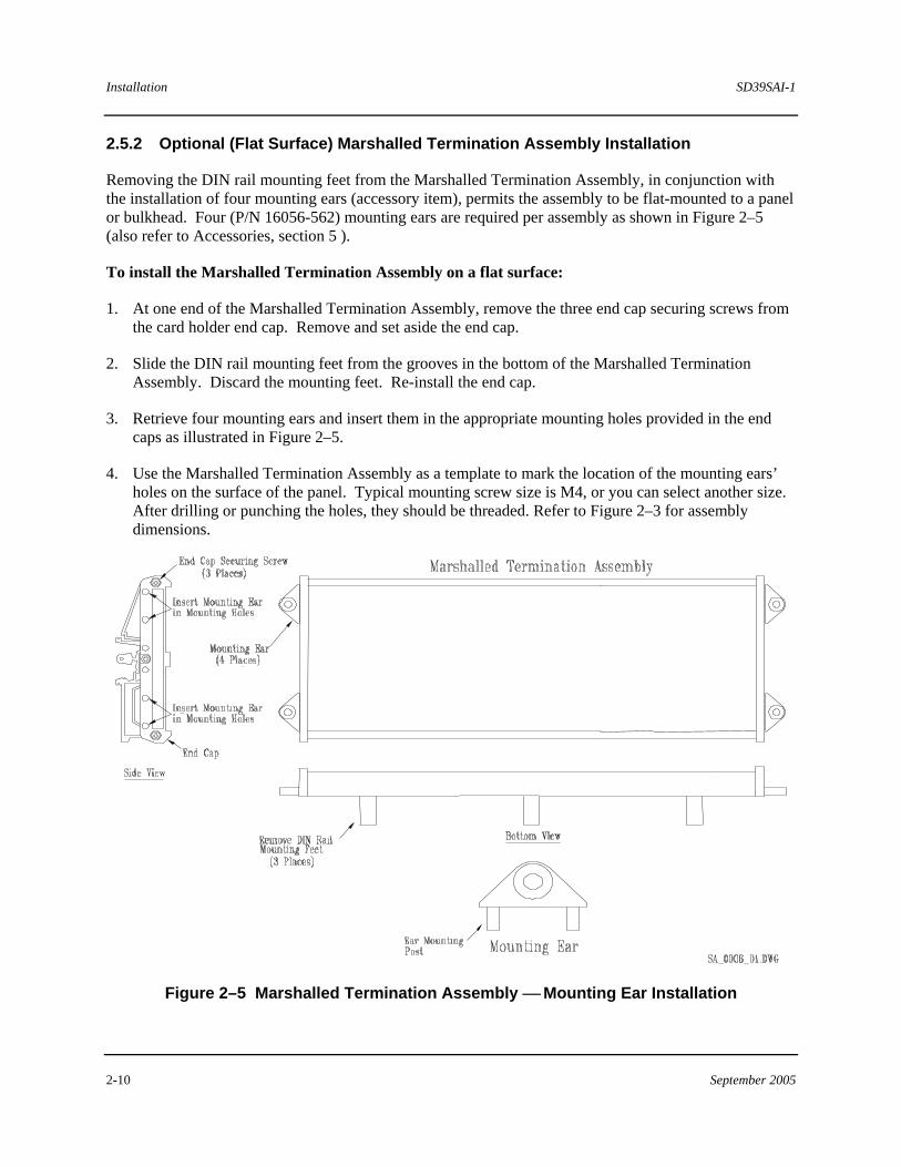
2.5.2 Optional (Flat Surface) Marshalled Termination Assembly Installation
Removing the DIN rail mounting feet from the Marshalled Termination Assembly, in conjunction with the installation of four mounting ears (accessory item), permits the assembly to be flat-mounted to a panel or bulkhead. Four (P/N 16056-562) mounting ears are required per assembly as shown in Figure 2–5 (also refer to Accessories, section 5 ).
To install the Marshalled Termination Assembly on a flat surface:
1. At one end of the Marshalled Termination Assembly, remove the three end cap securing screws from the card holder end cap. Remove and set aside the end cap.
2. Slide the DIN rail mounting feet from the grooves in the bottom of the Marshalled Termination Assembly. Discard the mounting feet. Re-install the end cap.
3. Retrieve four mounting ears and insert them in the appropriate mounting holes provided in the end caps as illustrated in Figure 2–5.
4. Use the Marshalled Termination Assembly as a template to mark the location of the mounting ears’ holes on the surface of the panel. Typical mounting screw size is M4, or you can select another size. After drilling or punching the holes, they should be threaded. Refer to Figure 2–3 for assembly dimensions.
Figure 2–5 Marshalled Termination Assembly ⎯ Mounting Ear Installation
SD39SAI-1 Installation
September 2005 2-11
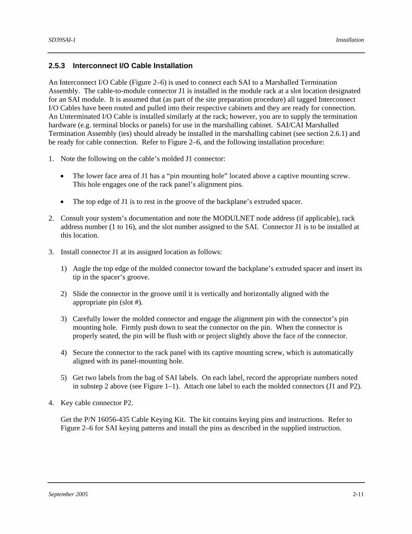
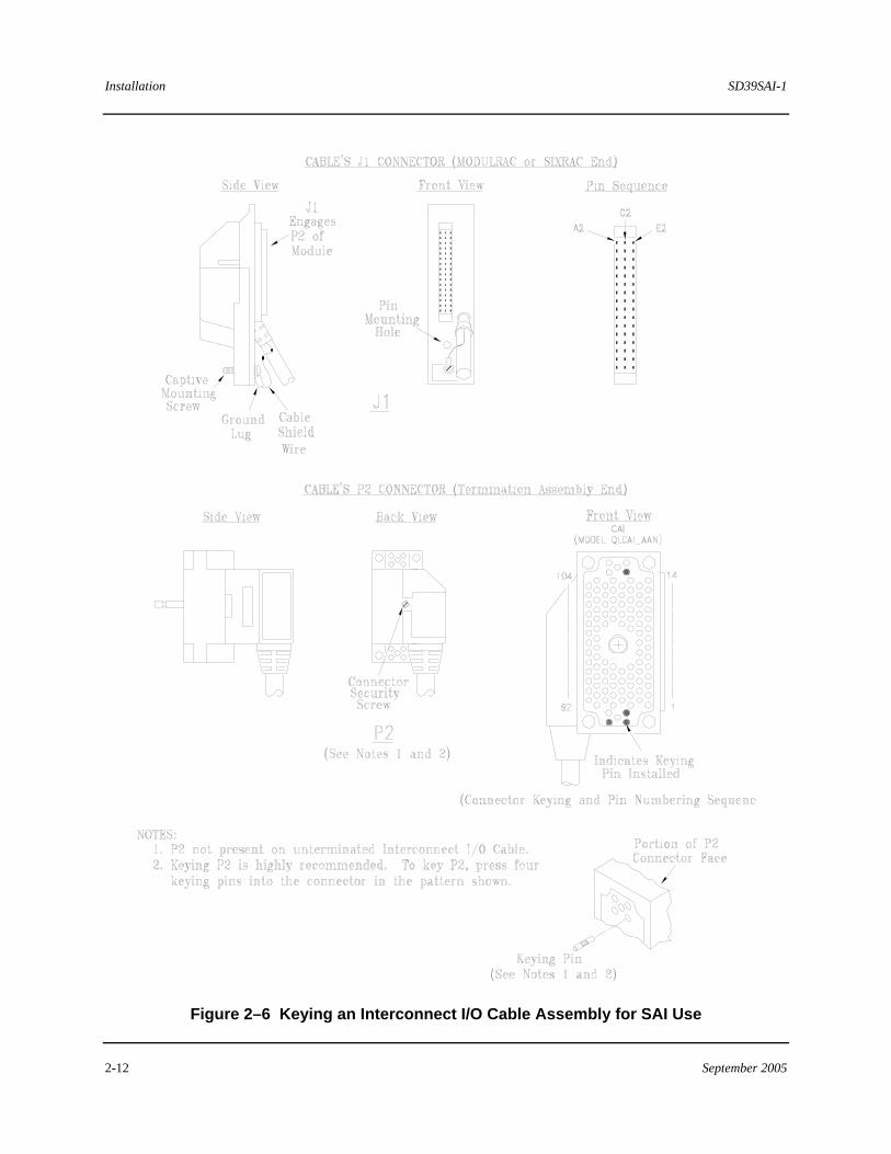
2.5.3 Interconnect I/O Cable Installation
An Interconnect I/O Cable (Figure 2–6) is used to connect each SAI to a Marshalled Termination Assembly. The cable-to-module connector J1 is installed in the module rack at a slot location designated for an SAI module. It is assumed that (as part of the site preparation procedure) all tagged Interconnect I/O Cables have been routed and pulled into their respective cabinets and they are ready for connection. An Unterminated I/O Cable is installed similarly at the rack; however, you are to supply the termination hardware (e.g. terminal blocks or panels) for use in the marshalling cabinet. SAI/CAI Marshalled Termination Assembly (ies) should already be installed in the marshalling cabinet (see section 2.6.1) and be ready for cable connection. Refer to Figure 2–6, and the following installation procedure:
1. Note the following on the cable’s molded J1 connector:
• The lower face area of J1 has a “pin mounting hole” located above a captive mounting screw. This hole engages one of the rack panel’s alignment pins.
• The top edge of J1 is to rest in the groove of the backplane’s extruded spacer.
2. Consult your system’s documentation and note the MODULNET node address (if applicable), rack address number (1 to 16), and the slot number assigned to the SAI. Connector J1 is to be installed at this location.
3. Install connector J1 at its assigned location as follows:
1) Angle the top edge of the molded connector toward the backplane’s extruded spacer and insert its tip in the spacer’s groove.
2) Slide the connector in the groove until it is vertically and horizontally aligned with the appropriate pin (slot #).
3) Carefully lower the molded connector and engage the alignment pin with the connector’s pin mounting hole. Firmly push down to seat the connector on the pin. When the connector is properly seated, the pin will be flush with or project slightly above the face of the connector.
4) Secure the connector to the rack panel with its captive mounting screw, which is automatically aligned with its panel-mounting hole.
5) Get two labels from the bag of SAI labels. On each label, record the appropriate numbers noted in substep 2 above (see Figure 1–1). Attach one label to each the molded connectors (J1 and P2).
4. Key cable connector P2.
Get the P/N 16056-435 Cable Keying Kit. The kit contains keying pins and instructions. Refer to Figure 2–6 for SAI keying patterns and install the pins as described in the supplied instruction.
Installation SD39SAI-1
2-12 September 2005
Figure 2–6 Keying an Interconnect I/O Cable Assembly for SAI Use
SD39SAI-1 Installation
September 2005 2-13
5. Connect the free end of the I/O Cable Assembly to its respective I/O termination assembly. Perform the appropriate procedure depending on cable type:
For Interconnect I/O Cable Assembly (P2 installed)
1) Connect cable connector P2 (Figure 2-6) to the J1 connector on the Marshalled Termination Assembly (Figure 1-1). An alignment pin projecting from the face of J1 ensures a correct mating.
2) Press P2 firmly onto J1.
3) Torque the securing screw on the top of P2’s connector shell to 50 inch-pounds maximum.
For Unterminated I/O Cable Assembly (P2 not installed)
Refer to Table 2–2 in Subsection 2.8 for the color code and function of each unterminated I/O wire. Refer to the wiring diagrams for your system to determine where to make the proper cable connections to the termination assembly.
6. For redundant SAIs, connect the redundant I/O Cable Assembly as described above in step 5.
2.6 SAI Installation
Modules are shipped individually packaged in protective, sealed, static shielding bags. Refer to section 2.4.4 for module handling considerations.
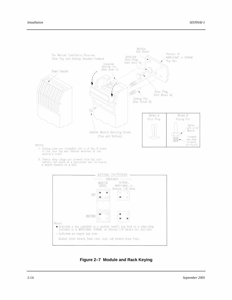
Each slot and each module must be keyed to prevent accidental installation of a module into an incompatible slot, which may impair system performance. Module and rack keying is highly recommended; see Figure 2–7.
• Modules are keyed at the factory. The keying pattern is unique to each module type (e.g. ACM, SAI, SDM, IDO).
• A factory-assembled rack is keyed at the factory. If you are assembling the rack on site, you must key each slot according to the module type assigned to it. The slot keying pattern complements the module’s keying pattern. Stop plugs are supplied with the rack.
• Before adding a module to a rack, be sure to key its slot.
Section 2.6.1 describes keying a slot. Section 2.6.2 describes installing the module in the rack.
Installation SD39SAI-1
2-14 September 2005
Figure 2–7 Module and Rack Keying
SD39SAI-1 Installation
September 2005 2-15
2.6.1 Module Rack Mechanical Keying
1. Get the rack Keying Kit supplied with the rack.
2. Refer to Figure 2–7 and note the rack-keying pattern applicable to the SAI. Also, locate the rack’s top and bottom rails.
3. Press the stop plugs into the appropriate key holes of the top and bottom rails as identified by the solid dot keying patterns in the figure.
2.6.2 Module Installation
1. Where applicable, refer to your system documentation and note the assigned rack and slot numbers for the module to be installed.
2. Remove the SAI from its static shielding bag and ensure that the module is keyed. Also, check the slot to be sure it is keyed. If required, refer to section 2.6.1 for rack keying information.
3. Insert the module in the assigned slot. Use uniform pressure to firmly seat the module in the backplane and transition board connectors. If the module does not seat properly, check its keying pattern. A properly seated module has the rear of its bezel flush against the rack’s front rails. A keyed module that is not matched to a slot does not engage the Backplane or transition board connectors or seat flush against the rack’s front rails.
4. As shown in Figure 2–7, pivot open the bezel’s pivoting top and bottom handles to expose the slotted captive mounting screws then secure the module to the top and bottom rails. Close the bezel’s handles when finished.
CAUTION
Do not use the captive mounting screws to seat the module. Damage to the bezel can result. Properly seat the module before tightening the captive screws.
2.7 Electrical Installation
This section describes SAI I/O wiring connections to a remotely mounted Marshalled Termination Assembly. It is assumed that tagged field I/O wires have been pulled into the cabinet and are ready for preparation and connection.
Installation SD39SAI-1
2-16 September 2005
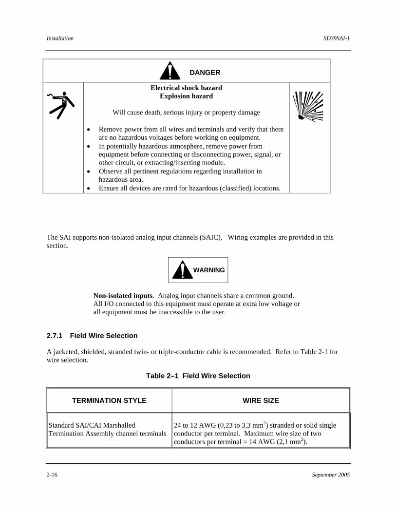
DANGER
Electrical shock hazard Explosion hazard
Will cause death, serious injury or property damage
• Remove power from all wires and terminals and verify that there
are no hazardous voltages before working on equipment. • In potentially hazardous atmosphere, remove power from
equipment before connecting or disconnecting power, signal, or other circuit, or extracting/inserting module.
• Observe all pertinent regulations regarding installation in hazardous area.
• Ensure all devices are rated for hazardous (classified) locations.
The SAI supports non-isolated analog input channels (SAIC). Wiring examples are provided in this section.
WARNING
Non-isolated inputs. Analog input channels share a common ground. All I/O connected to this equipment must operate at extra low voltage or all equipment must be inaccessible to the user.
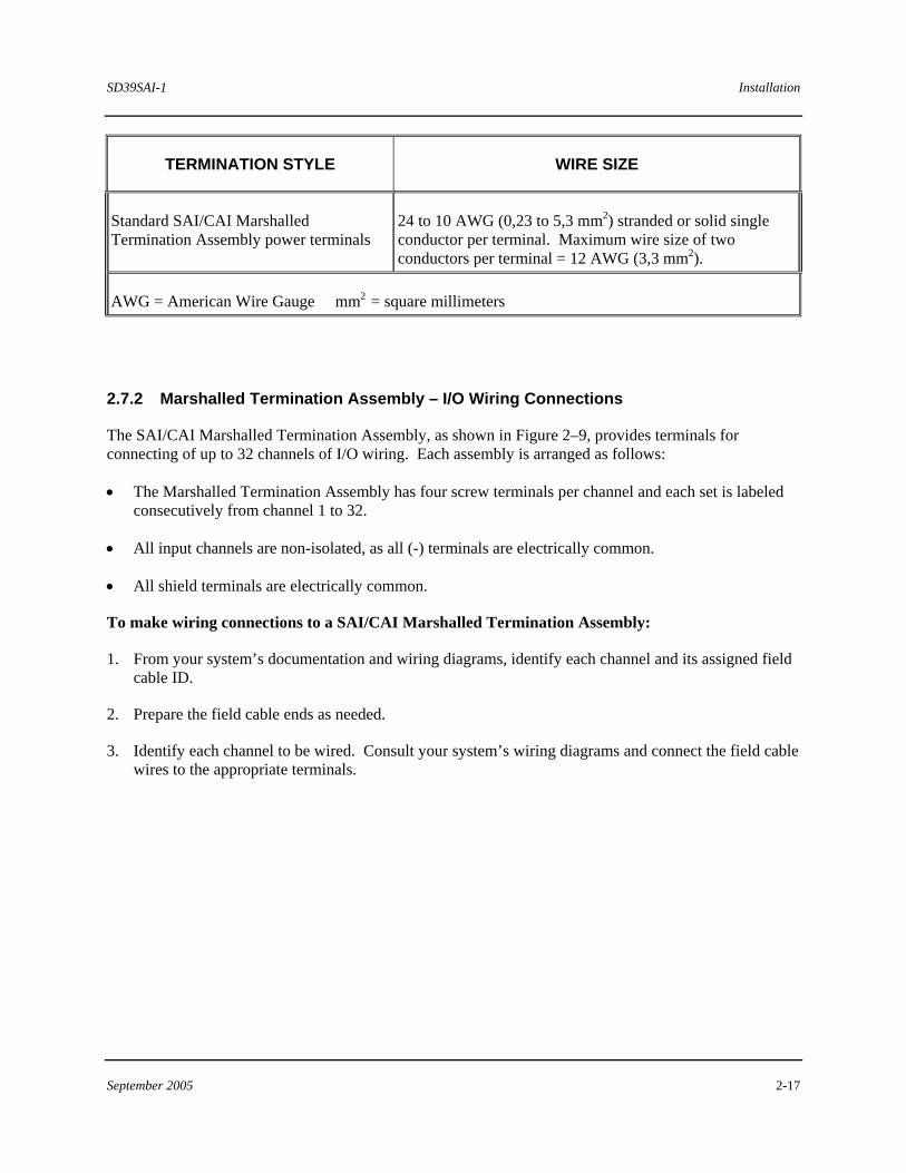
2.7.1 Field Wire Selection
A jacketed, shielded, stranded twin- or triple-conductor cable is recommended. Refer to Table 2-1 for wire selection.
Table 2–1 Field Wire Selection
TERMINATION STYLE WIRE SIZE
Standard SAI/CAI Marshalled Termination Assembly channel terminals
24 to 12 AWG (0,23 to 3,3 mm2) stranded or solid single conductor per terminal. Maximum wire size of two conductors per terminal = 14 AWG (2,1 mm2).
SD39SAI-1 Installation
September 2005 2-17
TERMINATION STYLE WIRE SIZE
Standard SAI/CAI Marshalled Termination Assembly power terminals
24 to 10 AWG (0,23 to 5,3 mm2) stranded or solid single conductor per terminal. Maximum wire size of two conductors per terminal = 12 AWG (3,3 mm2).
AWG = American Wire Gauge mm2 = square millimeters
2.7.2 Marshalled Termination Assembly – I/O Wiring Connections
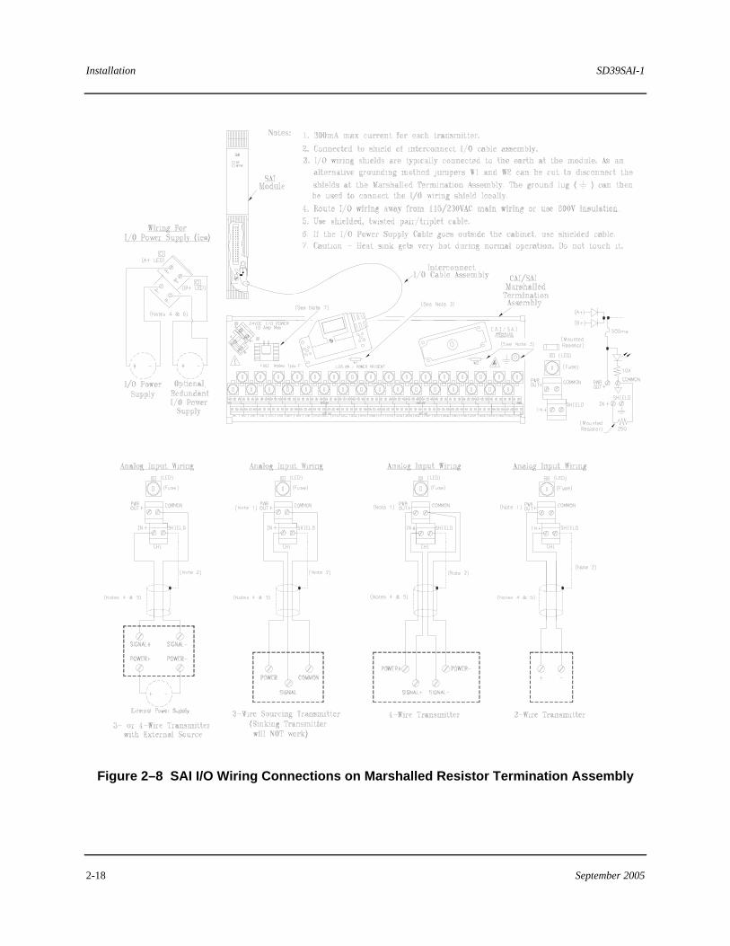
The SAI/CAI Marshalled Termination Assembly, as shown in Figure 2–9, provides terminals for connecting of up to 32 channels of I/O wiring. Each assembly is arranged as follows:
• The Marshalled Termination Assembly has four screw terminals per channel and each set is labeled consecutively from channel 1 to 32.
• All input channels are non-isolated, as all (-) terminals are electrically common.
• All shield terminals are electrically common.
To make wiring connections to a SAI/CAI Marshalled Termination Assembly:
1. From your system’s documentation and wiring diagrams, identify each channel and its assigned field cable ID.
2. Prepare the field cable ends as needed.
3. Identify each channel to be wired. Consult your system’s wiring diagrams and connect the field cable wires to the appropriate terminals.
Installation SD39SAI-1
2-18 September 2005
Figure 2–8 SAI I/O Wiring Connections on Marshalled Resistor Termination Assembly
SD39SAI-1 Installation
September 2005 2-19
2.7.3 Unterminated I/O Cable Assembly Connections
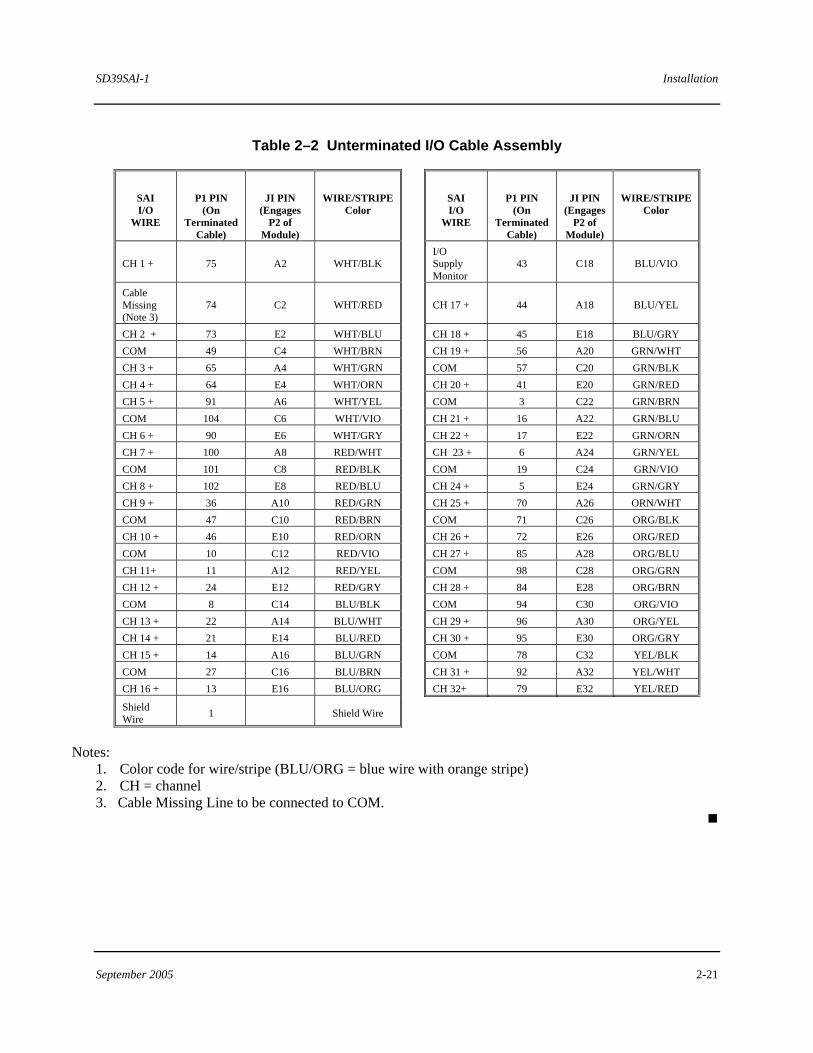
Connect field devices to user-supplied termination hardware (e.g. terminal blocks). Table 2–2 lists the wire color and identification information needed for termination. Refer to your system’s wiring diagrams as necessary.
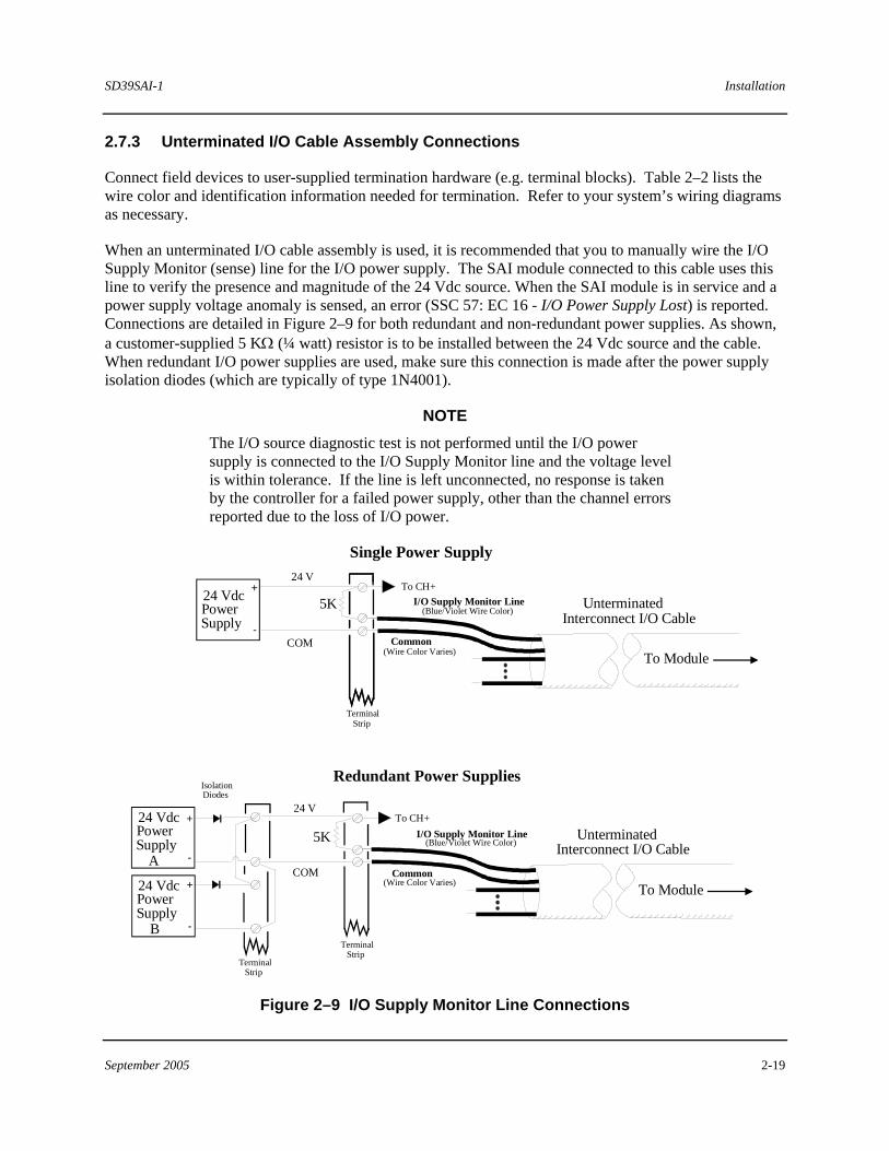
When an unterminated I/O cable assembly is used, it is recommended that you to manually wire the I/O Supply Monitor (sense) line for the I/O power supply. The SAI module connected to this cable uses this line to verify the presence and magnitude of the 24 Vdc source. When the SAI module is in service and a power supply voltage anomaly is sensed, an error (SSC 57: EC 16 - I/O Power Supply Lost) is reported. Connections are detailed in Figure 2–9 for both redundant and non-redundant power supplies. As shown, a customer-supplied 5 KΩ (¼ watt) resistor is to be installed between the 24 Vdc source and the cable. When redundant I/O power supplies are used, make sure this connection is made after the power supply isolation diodes (which are typically of type 1N4001).
NOTE The I/O source diagnostic test is not performed until the I/O power supply is connected to the I/O Supply Monitor line and the voltage level is within tolerance. If the line is left unconnected, no response is taken by the controller for a failed power supply, other than the channel errors reported due to the loss of I/O power.
Interconnect I/O Cable
+
-
PowerSupply
24 V
24 Vdc
Single Power Supply
COM
5K Unterminated
To Module
I/O Supply Monitor Line(Blue/Violet Wire Color)
Common(Wire Color Varies)
Terminal Strip
Interconnect I/O Cable
+
-
PowerSupply
24 V24 Vdc
Redundant Power Supplies
COM
Unterminated
To Module
I/O Supply Monitor Line(Blue/Violet Wire Color)
Common(Wire Color Varies)
Terminal Strip
+
-
PowerSupply
24 Vdc
Terminal Strip
A
B
To CH+
To CH+
Isolation Diodes
5K
Figure 2–9 I/O Supply Monitor Line Connections
Installation SD39SAI-1
2-20 September 2005
2.8 Configuration
The SAI and its associated control module (Advanced Control Module) must be configured using the 4-mation Configuration software along with the appropriate APACS+ software. The 4-mation software runs on a Microsoft Windows-based personal computer (PC). It is a graphical software tool for configuring control, communication and I/O modules within an APACS+ process automation system. When the configuration is complete, it is to be transferred to the control module. Once transferred, the SAI-portion of the configuration is automatically forwarded from the control module to the SAI. During online operation, the control module executes the configuration while controlling the operation of its I/O modules.
There are many PC-based hardware layouts possible for setting up a 4-mation-based configuration station. Two examples are listed here:
• Run 4-mation on a Rack-mounted Industrial Server (RIS).
• Run 4-mation on a PC
For additional information about 4-mation, refer to the related literature listed in section 1.4. SAI-specific information is presented in APACS+ I/O Module Configuration (document number CG39-24).
SD39SAI-1 Installation
September 2005 2-21
Table 2–2 Unterminated I/O Cable Assembly
SAI I/O
WIRE
P1 PIN
(On Terminated
Cable)
JI PIN
(Engages P2 of
Module)
WIRE/STRIPE
Color
SAI I/O
WIRE
P1 PIN
(On Terminated
Cable)
JI PIN
(Engages P2 of
Module)
WIRE/STRIPE
Color
CH 1 + 75 A2 WHT/BLK I/O
Supply Monitor
43 C18 BLU/VIO
Cable Missing (Note 3)
74 C2 WHT/RED
CH 17 + 44 A18 BLU/YEL
CH 2 + 73 E2 WHT/BLU CH 18 + 45 E18 BLU/GRY COM 49 C4 WHT/BRN CH 19 + 56 A20 GRN/WHT CH 3 + 65 A4 WHT/GRN COM 57 C20 GRN/BLK CH 4 + 64 E4 WHT/ORN CH 20 + 41 E20 GRN/RED CH 5 + 91 A6 WHT/YEL COM 3 C22 GRN/BRN COM 104 C6 WHT/VIO CH 21 + 16 A22 GRN/BLU CH 6 + 90 E6 WHT/GRY CH 22 + 17 E22 GRN/ORN CH 7 + 100 A8 RED/WHT CH 23 + 6 A24 GRN/YEL COM 101 C8 RED/BLK COM 19 C24 GRN/VIO CH 8 + 102 E8 RED/BLU CH 24 + 5 E24 GRN/GRY CH 9 + 36 A10 RED/GRN CH 25 + 70 A26 ORN/WHT COM 47 C10 RED/BRN COM 71 C26 ORG/BLK CH 10 + 46 E10 RED/ORN CH 26 + 72 E26 ORG/RED COM 10 C12 RED/VIO CH 27 + 85 A28 ORG/BLU CH 11+ 11 A12 RED/YEL COM 98 C28 ORG/GRN CH 12 + 24 E12 RED/GRY CH 28 + 84 E28 ORG/BRN COM 8 C14 BLU/BLK COM 94 C30 ORG/VIO CH 13 + 22 A14 BLU/WHT CH 29 + 96 A30 ORG/YEL CH 14 + 21 E14 BLU/RED CH 30 + 95 E30 ORG/GRY CH 15 + 14 A16 BLU/GRN COM 78 C32 YEL/BLK COM 27 C16 BLU/BRN CH 31 + 92 A32 YEL/WHT CH 16 + 13 E16 BLU/ORG CH 32+ 79 E32 YEL/RED
Shield Wire 1 Shield Wire
Notes: 1. Color code for wire/stripe (BLU/ORG = blue wire with orange stripe) 2. CH = channel 3. Cable Missing Line to be connected to COM.

SD39SAI-1 Maintenance
September 2005 3-1
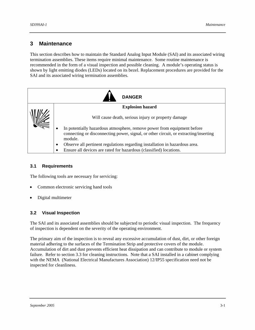
3 Maintenance
This section describes how to maintain the Standard Analog Input Module (SAI) and its associated wiring termination assemblies. These items require minimal maintenance. Some routine maintenance is recommended in the form of a visual inspection and possible cleaning. A module’s operating status is shown by light emitting diodes (LEDs) located on its bezel. Replacement procedures are provided for the SAI and its associated wiring termination assemblies.
DANGER
Explosion hazard
Will cause death, serious injury or property damage • In potentially hazardous atmosphere, remove power from equipment before
connecting or disconnecting power, signal, or other circuit, or extracting/inserting module.
• Observe all pertinent regulations regarding installation in hazardous area. • Ensure all devices are rated for hazardous (classified) locations.
3.1 Requirements
The following tools are necessary for servicing:
• Common electronic servicing hand tools
• Digital multimeter
3.2 Visual Inspection
The SAI and its associated assemblies should be subjected to periodic visual inspection. The frequency of inspection is dependent on the severity of the operating environment.
The primary aim of the inspection is to reveal any excessive accumulation of dust, dirt, or other foreign material adhering to the surfaces of the Termination Strip and protective covers of the module. Accumulation of dirt and dust prevents efficient heat dissipation and can contribute to module or system failure. Refer to section 3.3 for cleaning instructions. Note that a SAI installed in a cabinet complying with the NEMA (National Electrical Manufactures Association) 12/IP55 specification need not be inspected for cleanliness.
Maintenance SD39SAI-1
3-2 September 2005
3.3 Cleaning
Cleaning the SAI involves brushing or vacuuming the protective covers to restore cooling efficiency that degrades by the accumulated dust, dirt, or other foreign materials.
Cleaning a SAI/CAI Marshalled Termination Assembly involves careful brushing and vacuuming to remove accumulated dust and dirt harboring chemical particulate that can accelerate terminal or connector contact corrosion. When cleaning the termination hardware area, be careful not to disturb the wiring.
WARNING
Electrical shock hazard. Remove power from all involved wires and terminals.
3.4 Troubleshooting
A module’s operating status and errors are indicated by its status LEDs. Also, error codes and related diagnostic messages are displayed by the 4-mation configuration software and the Diagnostic Logger utility. Details of error codes and messages are available in the following documents:
• 4-mation Software Messages and Error Codes (document number CG39-21, located in binder UM39-11)
• Module Diagnostic Error Codes (document number CG39-19, located in binder UM39-14)
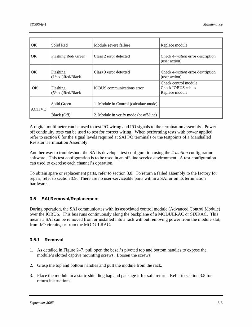
Module status LEDs are located on the SAI’s bezel. Note LED indications, then refer to Table 3-1 for SAI status and the listed documents to determine the appropriate course of action.
Interconnect I/O Cable pin assignments for SAI applications are provided in Table 2–2. These are provided for troubleshooting a suspect cable. As necessary, check field wiring and field-located devices.
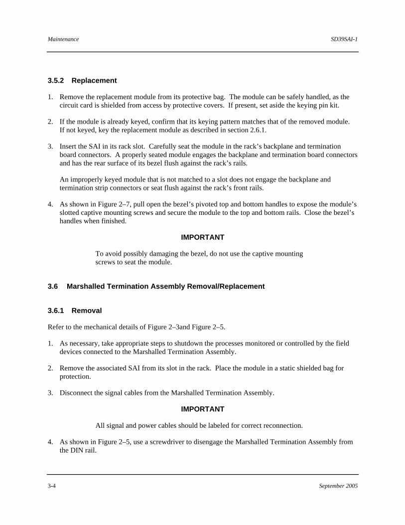
Table 3–1 LED Indications
LED LED INDICATION MODULE STATUS ACTION
OK Black (Off) No 24V power input to module Module on-board power supply failure
Troubleshoot or replace 24V power supply Properly seat the module Replace module
OK Solid Green Module OK. Configured, with no faults or failures.
Normal, no action required.
OK Flashing Green/ Black Module not configured. No faults or failures.
Download configuration
SD39SAI-1 Maintenance
September 2005 3-3
OK Solid Red Module severe failure Replace module
OK Flashing Red/ Green Class 2 error detected Check 4-mation error description (user action).
OK Flashing (1/sec.)Red/Black
Class 3 error detected Check 4-mation error description (user action).
OK Flashing (5/sec.)Red/Black
IOBUS communications error Check control module Check IOBUS cables Replace module
Solid Green 1. Module in Control (calculate mode) ACTIVE
Black (Off) 2. Module in verify mode (or off-line)
A digital multimeter can be used to test I/O wiring and I/O signals to the termination assembly. Power-off continuity tests can be used to test for correct wiring. When performing tests with power applied, refer to section 6 for the signal levels required at SAI I/O terminals or the testpoints of a Marshalled Resistor Termination Assembly.
Another way to troubleshoot the SAI is develop a test configuration using the 4-mation configuration software. This test configuration is to be used in an off-line service environment. A test configuration can used to exercise each channel’s operation.
To obtain spare or replacement parts, refer to section 3.8. To return a failed assembly to the factory for repair, refer to section 3.9. There are no user-serviceable parts within a SAI or on its termination hardware.
3.5 SAI Removal/Replacement
During operation, the SAI communicates with its associated control module (Advanced Control Module) over the IOBUS. This bus runs continuously along the backplane of a MODULRAC or SIXRAC. This means a SAI can be removed from or installed into a rack without removing power from the module slot, from I/O circuits, or from the MODULRAC.
3.5.1 Removal
1. As detailed in Figure 2–7, pull open the bezel’s pivoted top and bottom handles to expose the module’s slotted captive mounting screws. Loosen the screws.
2. Grasp the top and bottom handles and pull the module from the rack.
3. Place the module in a static shielding bag and package it for safe return. Refer to section 3.8 for return instructions.
Maintenance SD39SAI-1
3-4 September 2005
3.5.2 Replacement
1. Remove the replacement module from its protective bag. The module can be safely handled, as the circuit card is shielded from access by protective covers. If present, set aside the keying pin kit.
2. If the module is already keyed, confirm that its keying pattern matches that of the removed module. If not keyed, key the replacement module as described in section 2.6.1.
3. Insert the SAI in its rack slot. Carefully seat the module in the rack’s backplane and termination board connectors. A properly seated module engages the backplane and termination board connectors and has the rear surface of its bezel flush against the rack’s rails.
An improperly keyed module that is not matched to a slot does not engage the backplane and termination strip connectors or seat flush against the rack’s front rails.
4. As shown in Figure 2–7, pull open the bezel’s pivoted top and bottom handles to expose the module’s slotted captive mounting screws and secure the module to the top and bottom rails. Close the bezel’s handles when finished.
IMPORTANT
To avoid possibly damaging the bezel, do not use the captive mounting screws to seat the module.
3.6 Marshalled Termination Assembly Removal/Replacement
3.6.1 Removal
Refer to the mechanical details of Figure 2–3and Figure 2–5.
1. As necessary, take appropriate steps to shutdown the processes monitored or controlled by the field devices connected to the Marshalled Termination Assembly.
2. Remove the associated SAI from its slot in the rack. Place the module in a static shielded bag for protection.
3. Disconnect the signal cables from the Marshalled Termination Assembly.
IMPORTANT
All signal and power cables should be labeled for correct reconnection.
4. As shown in Figure 2–5, use a screwdriver to disengage the Marshalled Termination Assembly from the DIN rail.
SD39SAI-1 Maintenance
September 2005 3-5
3.6.2 Replacement
1. Refer to the installation procedure in section 2.5 and install the replacement Marshalled Termination Assembly.
2. Reconnect the signal cables.
3. Install the SAI module. See section 3.5.
3.7 Interconnect I/O Cable Removal/Replacement
3.7.1 Removal
Refer to the mechanical details of Figure 2–2.
1. As necessary, take appropriate steps to shutdown the processes monitored or controlled by the field devices connected to the Marshalled Termination Assembly.
2. Remove the associated SAI from its slot in the rack. Place the module in a static shielded bag for protection.
3. Disconnect the Interconnect I/O Cable Assembly connector P2 or individual connections from the termination assembly. All individual connections should be labeled for correct reconnection.
4. Loosen the captive mounting screws on the cable connector. Gently lift the bottom of the connector in an arc until the connector is free of its alignment pin. Pull the top of the cable connector from the grooved backplane spacer and lift it away from the rack.
5. Remove the Interconnect I/O Cable Assembly from the cable tray or other cable routing equipment.
3.7.2 Replacement
Refer to the mechanical details in Figure 2–2.
1. Route the Interconnect I/O Cable Assembly between the MODULRAC (or SIXRAC) and the marshalling cabinet.
2. Label and key the replacement cable as described in section 2.5.3
3. Reconnect replacement cable as described in section 2.7.3.
4. Install the SAI. See section 2.6.
Maintenance SD39SAI-1
3-6 September 2005
3.8 Spare and Replacement Parts
One spare Standard Analog Input Module should be stocked for every 1 to 10 in service. Spare and replacement assemblies can be ordered from one of the addresses in the Warranty statement or through a local Siemens representative. Assembly part numbers are stated in section 5 and printed on most modules.
When ordering, provide the model number from the module's nameplate to be replaced or spared. A purchase order number should also be included.
There are no user-serviceable parts within SAI or on its termination hardware.
3.9 Maintenance Records
An accurate record keeping system for tracking maintenance operations should be established and kept up to date. Data extracted from the record can serve as a base for ordering maintenance supplies, including spare parts. The record can also be useful as a troubleshooting tool. In addition, maintenance records may be required to provide documentary information in association with a service contract. It is suggested that the following information be recorded:
• Date of service incident • Name or initials of service person • Brief description of incident symptoms and repairs performed • Replacement part or assembly number • Software code of original part • Software code of replacement part • Serial number of original part • Serial number of replacement part • Issue number of original circuit module • Issue number of replacement circuit module • Displayed error codes/channel states from module LEDs, user interface, and configuration software • Date of completion
SD39SAI-1 Circuit Description
September 2005 4-1
4 Circuit Description
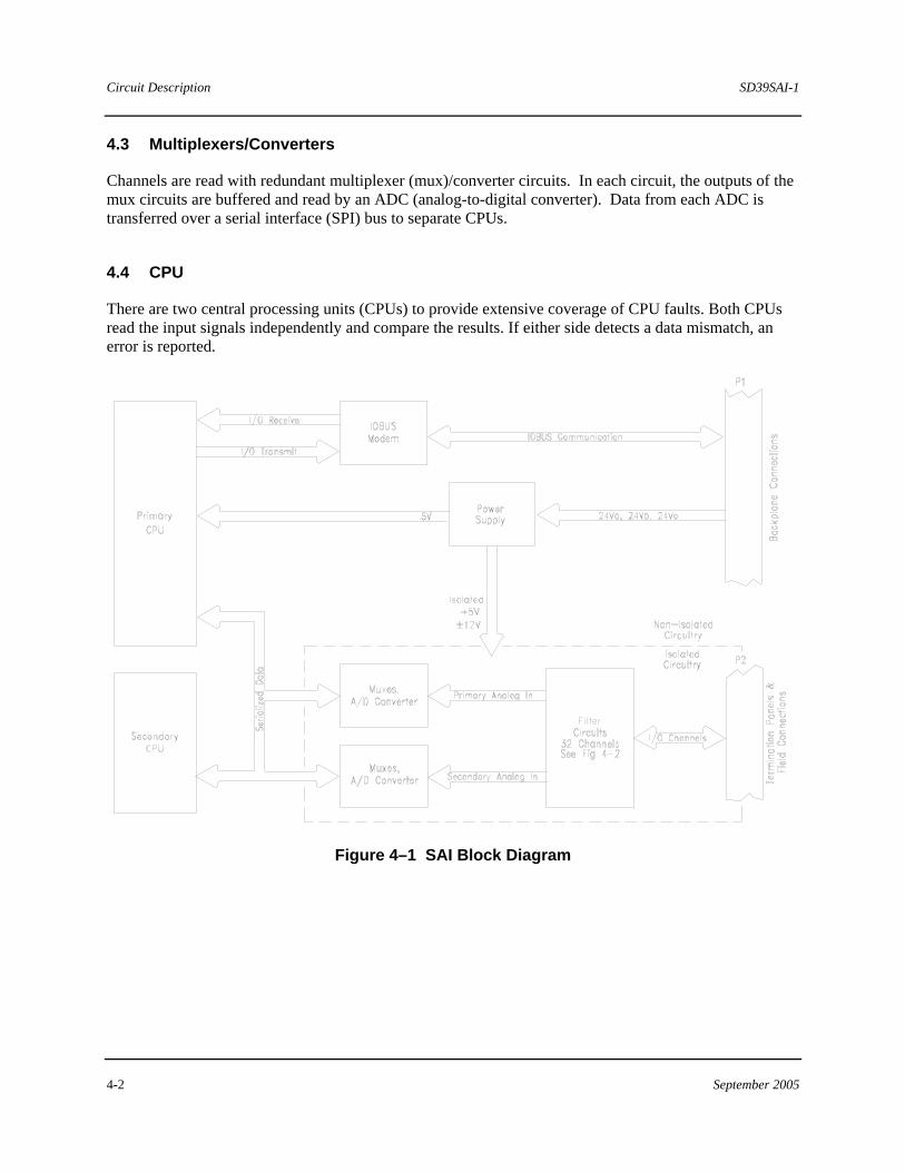
The Standard Analog Input Module (SAI) receives signals from 2, 3 or 4 wire field devices connected to 32 channels. Input signals are digitized by the SAI and transferred to an APACS+ control module (CCM/ACM+) via the IOBUS.
The Standard Analog Input Module consists of the following circuit elements:
• Dual Central Processing Units (CPUs)
• Dual A/D Circuits
• Memory (RAM, ROM, and EEPROM)
• Redundant IOBUS Interface
• 32 Channels of Analog Input Circuits
• Isolated and Non Isolated Power Sources
• LED Indicators
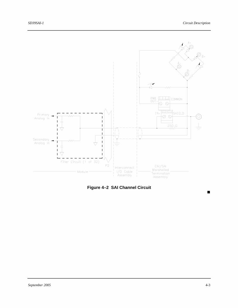
Figure 4–1 shows a simplified block diagram of the SAI. Figure 4-2 presents a schematic of the circuitry used in one of the 32 identical, but configurable I/O channels.
4.1 Isolated Power Supply
The on-board power converter incorporates a switching regulator to produce a non-isolated +5 V and isolated ±12 V. Power for the converters is supplied by dropping the +12Vdc unregulated and isolated supply to +5 Vdc using linear regulator.
4.2 IOBUS Modem
The IOBUS elements consist of an IOBUS Modem and dual IOBUS Line Drivers/Receivers. The CPU supervises IOBUS communications through handshaking operations with the IOBUS Modem. The IOBUS Modem performs the following:
• Converts received IOBUS data into a format for data-processing.
• Converts digitized field data from a CPU into a format for transmission over the IOBUS to a control module (CCM).
Circuit Description SD39SAI-1
4-2 September 2005
4.3 Multiplexers/Converters
Channels are read with redundant multiplexer (mux)/converter circuits. In each circuit, the outputs of the mux circuits are buffered and read by an ADC (analog-to-digital converter). Data from each ADC is transferred over a serial interface (SPI) bus to separate CPUs.
4.4 CPU
There are two central processing units (CPUs) to provide extensive coverage of CPU faults. Both CPUs read the input signals independently and compare the results. If either side detects a data mismatch, an error is reported.
Figure 4–1 SAI Block Diagram
SD39SAI-1 Circuit Description
September 2005 4-3
Figure 4–2 SAI Channel Circuit
Circuit Description SD39SAI-1
4-4 September 2005
SD39SAI-1 Model Designation
September 2005 5-1
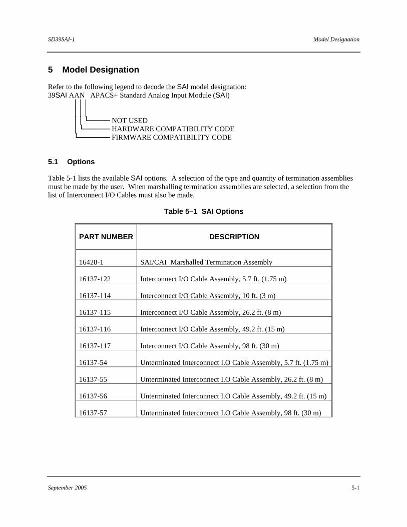
5 Model Designation
Refer to the following legend to decode the SAI model designation: 39SAI AAN APACS+ Standard Analog Input Module (SAI) │││ │││ ││└──── NOT USED │└───── HARDWARE COMPATIBILITY CODE └────── FIRMWARE COMPATIBILITY CODE
5.1 Options
Table 5-1 lists the available SAI options. A selection of the type and quantity of termination assemblies must be made by the user. When marshalling termination assemblies are selected, a selection from the list of Interconnect I/O Cables must also be made.
Table 5–1 SAI Options
PART NUMBER DESCRIPTION
16428-1 SAI/CAI Marshalled Termination Assembly
16137-122 Interconnect I/O Cable Assembly, 5.7 ft. (1.75 m)
16137-114 Interconnect I/O Cable Assembly, 10 ft. (3 m)
16137-115 Interconnect I/O Cable Assembly, 26.2 ft. (8 m)
16137-116 Interconnect I/O Cable Assembly, 49.2 ft. (15 m)
16137-117 Interconnect I/O Cable Assembly, 98 ft. (30 m)
16137-54 Unterminated Interconnect I.O Cable Assembly, 5.7 ft. (1.75 m)
16137-55 Unterminated Interconnect I.O Cable Assembly, 26.2 ft. (8 m)
16137-56 Unterminated Interconnect I.O Cable Assembly, 49.2 ft. (15 m)
16137-57 Unterminated Interconnect I.O Cable Assembly, 98 ft. (30 m)
Model Designation SD39SAI-1
5-2 September 2005
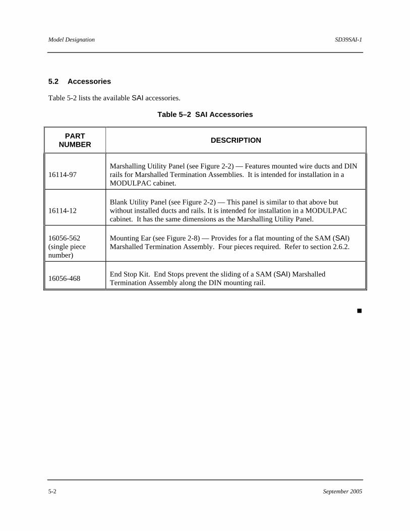
5.2 Accessories
Table 5-2 lists the available SAI accessories.
Table 5–2 SAI Accessories
PART NUMBER DESCRIPTION
16114-97 Marshalling Utility Panel (see Figure 2-2) — Features mounted wire ducts and DIN rails for Marshalled Termination Assemblies. It is intended for installation in a MODULPAC cabinet.
16114-12 Blank Utility Panel (see Figure 2-2) — This panel is similar to that above but without installed ducts and rails. It is intended for installation in a MODULPAC cabinet. It has the same dimensions as the Marshalling Utility Panel.
16056-562 (single piece number)
Mounting Ear (see Figure 2-8) — Provides for a flat mounting of the SAM (SAI) Marshalled Termination Assembly. Four pieces required. Refer to section 2.6.2.
16056-468 End Stop Kit. End Stops prevent the sliding of a SAM (SAI) Marshalled Termination Assembly along the DIN mounting rail.
SD39SAI-1 Specifications
September 2005 6-1
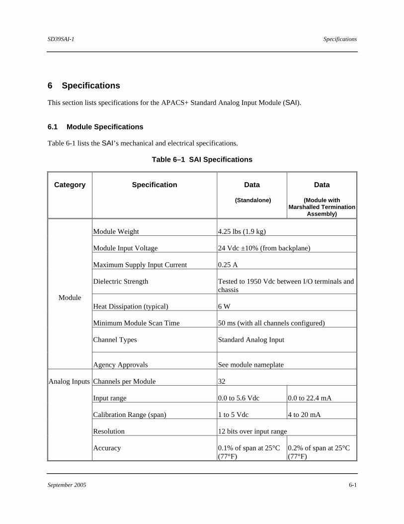
6 Specifications
This section lists specifications for the APACS+ Standard Analog Input Module (SAI).
6.1 Module Specifications
Table 6-1 lists the SAI’s mechanical and electrical specifications.
Table 6–1 SAI Specifications
Category Specification Data
(Standalone)
Data
(Module with Marshalled Termination
Assembly)
Module Weight 4.25 lbs (1.9 kg)
Module Input Voltage 24 Vdc ±10% (from backplane)
Maximum Supply Input Current 0.25 A
Dielectric Strength Tested to 1950 Vdc between I/O terminals and chassis
Heat Dissipation (typical) 6 W
Minimum Module Scan Time 50 ms (with all channels configured)
Channel Types Standard Analog Input
Module
Agency Approvals See module nameplate
Channels per Module 32
Input range 0.0 to 5.6 Vdc 0.0 to 22.4 mA
Calibration Range (span) 1 to 5 Vdc 4 to 20 mA
Resolution 12 bits over input range
Analog Inputs
Accuracy 0.1% of span at 25°C (77°F)
0.2% of span at 25°C (77°F)
Specifications SD39SAI-1
6-2 September 2005
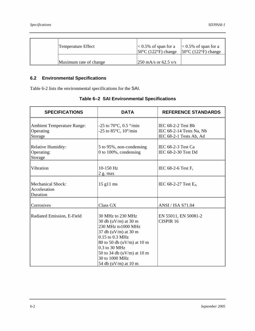
Temperature Effect < 0.5% of span for a 50°C (122°F) change
< 0.5% of span for a 50°C (122°F) change
Maximum rate of change 250 mA/s or 62.5 v/s
6.2 Environmental Specifications
Table 6-2 lists the environmental specifications for the SAI.
Table 6–2 SAI Environmental Specifications
SPECIFICATIONS DATA REFERENCE STANDARDS
Ambient Temperature Range: Operating Storage
-25 to 70°C, 0.5 °/min -25 to 85°C, 10°/min
IEC 68-2-2 Test Bb IEC 68-2-14 Tests Na, Nb IEC 68-2-1 Tests Ab, Ad
Relative Humidity: Operating: Storage
5 to 95%, non-condensing 0 to 100%, condensing
IEC 68-2-3 Test Ca IEC 68-2-30 Test Dd
Vibration 10-150 Hz 2 g. max
IEC 68-2-6 Test Fc
Mechanical Shock: Acceleration Duration
15 g11 ms IEC 68-2-27 Test EA
Corrosives Class GX ANSI / ISA S71.04
Radiated Emission, E-Field 30 MHz to 230 MHz 30 db (uV/m) at 30 m 230 MHz to1000 MHz 37 db (uV/m) at 30 m 0.15 to 0.3 MHz 80 to 50 db (uV/m) at 10 m 0.3 to 30 MHz 50 to 34 db (uV/m) at 10 m 30 to 1000 MHz 54 db (uV/m) at 10 m
EN 55011, EN 50081-2 CISPIR 16
SD39SAI-1 Specifications
September 2005 6-3
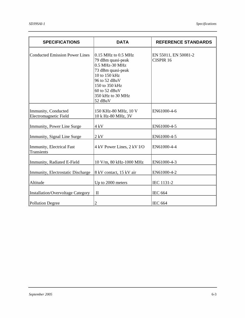
SPECIFICATIONS DATA REFERENCE STANDARDS
Conducted Emission Power Lines 0.15 MHz to 0.5 MHz 79 dBm quasi-peak 0.5 MHz-30 MHz 73 dBm quasi-peak 10 to 150 kHz 96 to 52 dBuV 150 to 350 kHz 60 to 52 dBuV 350 kHz to 30 MHz 52 dBuV
EN 55011, EN 50081-2 CISPIR 16
Immunity, Conducted Electromagnetic Field
150 KHz-80 MHz, 10 V 10 k Hz-80 MHz, 3V
EN61000-4-6
Immunity, Power Line Surge 4 kV EN61000-4-5
Immunity, Signal Line Surge 2 kV EN61000-4-5
Immunity, Electrical Fast Transients
4 kV Power Lines, 2 kV I/O EN61000-4-4
Immunity, Radiated E-Field 10 V/m, 80 kHz-1000 MHz EN61000-4-3
Immunity, Electrostatic Discharge 8 kV contact, 15 kV air EN61000-4-2
Altitude Up to 2000 meters IEC 1131-2
Installation/Overvoltage Category II IEC 664
Pollution Degree 2 IEC 664
Specifications SD39SAI-1
6-4 September 2005
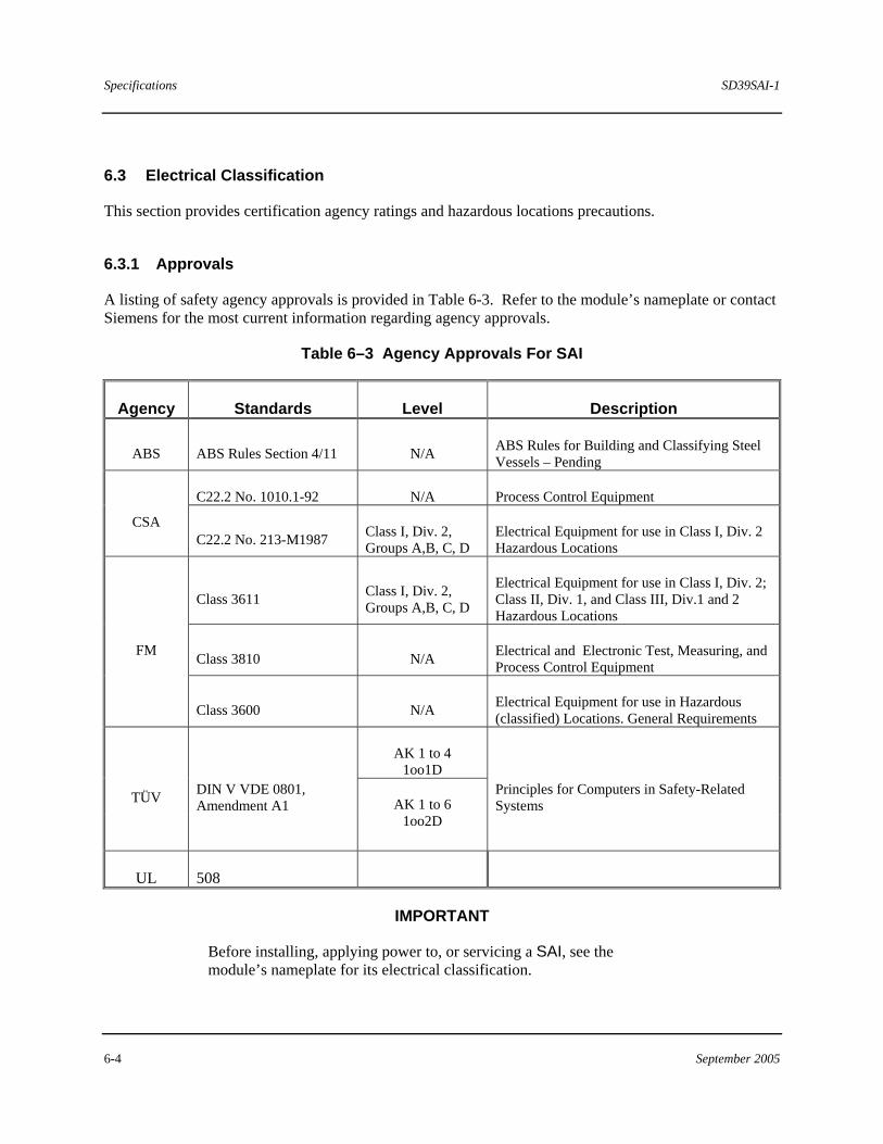
6.3 Electrical Classification
This section provides certification agency ratings and hazardous locations precautions.
6.3.1 Approvals
A listing of safety agency approvals is provided in Table 6-3. Refer to the module’s nameplate or contact Siemens for the most current information regarding agency approvals.
Table 6–3 Agency Approvals For SAI
Agency Standards Level Description
ABS ABS Rules Section 4/11 N/A ABS Rules for Building and Classifying Steel Vessels – Pending
C22.2 No. 1010.1-92 N/A Process Control Equipment
CSA C22.2 No. 213-M1987 Class I, Div. 2,
Groups A,B, C, D Electrical Equipment for use in Class I, Div. 2 Hazardous Locations
Class 3611 Class I, Div. 2, Groups A,B, C, D
Electrical Equipment for use in Class I, Div. 2; Class II, Div. 1, and Class III, Div.1 and 2 Hazardous Locations
Class 3810 N/A Electrical and Electronic Test, Measuring, and Process Control Equipment
FM
Class 3600 N/A Electrical Equipment for use in Hazardous (classified) Locations. General Requirements
AK 1 to 4 1oo1D
TÜV DIN V VDE 0801, Amendment A1 AK 1 to 6
1oo2D
Principles for Computers in Safety-Related Systems
UL 508
IMPORTANT
Before installing, applying power to, or servicing a SAI, see the module’s nameplate for its electrical classification.
SD39SAI-1 Specifications
September 2005 6-5
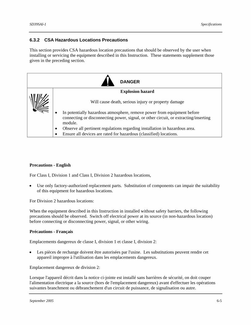
6.3.2 CSA Hazardous Locations Precautions
This section provides CSA hazardous location precautions that should be observed by the user when installing or servicing the equipment described in this Instruction. These statements supplement those given in the preceding section.
DANGER
Explosion hazard
Will cause death, serious injury or property damage • In potentially hazardous atmosphere, remove power from equipment before
connecting or disconnecting power, signal, or other circuit, or extracting/inserting module.
• Observe all pertinent regulations regarding installation in hazardous area. • Ensure all devices are rated for hazardous (classified) locations.
Precautions - English
For Class I, Division 1 and Class I, Division 2 hazardous locations,
• Use only factory-authorized replacement parts. Substitution of components can impair the suitability of this equipment for hazardous locations.
For Division 2 hazardous locations:
When the equipment described in this Instruction in installed without safety barriers, the following precautions should be observed. Switch off electrical power at its source (in non-hazardous location) before connecting or disconnecting power, signal, or other wiring.
Précautions - Français
Emplacements dangereux de classe I, division 1 et classe I, division 2:
• Les pièces de rechange doivent être autorisées par l'usine. Les substitutions peuvent rendre cet appareil impropre à l'utilisation dans les emplacements dangereux.
Emplacement dangereux de division 2:
Lorsque l'appareil décrit dans la notice ci-jointe est installé sans barrières de sécurité, on doit couper l'alimentation électrique a la source (hors de l'emplacement dangereux) avant d'effectuer les opérations suivantes branchment ou débranchement d'un circuit de puissance, de signalisation ou autre.
SD39SAI-1 Index
September 2005 Index-1
Index
4 4-mation, 1-1, 1-5, 2-20, 3-2, 3-3
A access
restricting, 2-3 agency certifications and approvals, 2-1, 6-4 APACS+, 1-1, 1-5, 2-20, 4-1, 5-1, 6-1 applications, 1-1
B BEZEL
DIAGNOSTIC LED CODES, 3-2
C configuration
software, 1-1 control module, 1-1, 2-20, 3-3, 4-1 CPU faults, 4-2
D DIN rail, 2-5, 2-6, 2-10, 3-4
E ESD (electrostatic discharge), 2-4, 2-15
I inspection
receipt of shipment, 2-3 visual, 3-1
Interconnect I/O Cable, 2-2, 2-4, 2-6, 2-11, 2-12, 2-13, 3-2, 3-5, 5-1
IOBUS, 1-1, 3-3, 4-1
K keying
cable, 2-5, 2-6, 2-11, 2-12 module, 2-14, 2-15
L LEDs
module status, 3-2 Local Termination Strip, 2-17 location
environment, 2-3
M maintenance records
checklist, 3-6 Marshalled Resistor Termination Assembly, 2-
18, 3-3 MODULPAC, 1-5
N nameplate, 2-1, 3-6, 6-1, 6-4 National Electrical Code (NEC), 2-1 non-isolated, 2-16, 2-17, 4-1
P PART NUMBERS
OPTIONS, 5-1
R rack address, 2-5, 2-11 redundancy, 2-5, 2-13, 4-2 ROM version number, 2-1
S serial number, 2-1 slot, 2-2, 2-5, 2-11, 2-13, 2-15, 3-3, 3-4, 3-5 spares, 3-6 specifications, 6-1–6-4 Standard Analog Module (SAM), 2-2 static. See ESD
T transition board, 2-15 troubleshooting, 1-1, 3-2, 3-3, 3-6 TÜV, 6-4
U Unterminated I/O Cable, 2-2, 2-11, 2-13, 2-19,
2-21 Unterminated Interconnect I.O Cable, 5-1 user-serviceable parts, 3-6
W wire colors
unterminated i/o cable assembly, 2-21 wiring
gague, 2-2 Unterminated I/O Cable, 2-19, 2-21
Index SD39SAI-1
Index-2 September 2005
wiring faults detecting, 2-2