Embed Size (px)
Citation preview

7252019 APCs Current-Gen SurgeArrest_ A Modern Tear-Downpdf
httpslidepdfcomreaderfullapcs-current-gen-surgearrest-a-modern-tear-downpdf 18
APCs Current-Gen SurgeArrest A Modern Tear-Down
By Daniel Sauvageau OCTOBER 9 2014 1200 AM
1 It Finally Arrived
2 Speaking Marketese
3 Wall Of Text
4 Table Of Contents
It took several weeks after we published Lets Take a Trip Inside a Power Strip to
line up a modern equivalent which wed use for a follow-up tear-down But its here
now Hidden somewhere under this ocean of bubble-wrap is the star of todays show
While I dig it out you may want to revisit my exploration of APCs old SurgeArrest
power strip the companys thoughtful response to my coverage and a deconstruction
of its BX1000 uninterruptible power supply in Tear-Down Lets Take a Trip Inside
UPS Ill be referring back to both features throughout todays piece
The packagings front side provides a succinct summary of the bars key features and a
photograph showing all of the major visual and functional aspects About 3kJ of surge
suppression and a $300000 protection guarantee sound fairly good But exactly what
goes on behind the scenes to give APC so much confidence We shall find out when w
get inside
The marketing department went wild on the back side giving potential buyers a walk-
through of each feature listed on the front On the bottom-left we see a RoHS
compliance declaration followed by the surge protection evaluation method and a list
package contents At the bottom-right we have the original owners equipment
protection policy summary followed by the French translation of surge testing and bo
contents
APC omitted headings on the English side When I do translations I obsess over maki
layouts match exactly whenever possible relatively minor discrepancies like that jump out at me more than they should
Included with the modern SurgeArrest are a user manual equipment protection policy a pair of APC-branded cable ties instead
of its predecessors plastic clip a gold-plated RG6 cable instead of the formers plain RG59 a telephone cable and of course t
power bar itself
E
983112
6
Bitdefender Antivirus Plus
7252019 APCs Current-Gen SurgeArrest_ A Modern Tear-Downpdf
httpslidepdfcomreaderfullapcs-current-gen-surgearrest-a-modern-tear-downpdf 28
5 Old Versus New
6 My Little Switches
7 Following Indications
As I mentioned in my original SurgeArrest tear-down I happen to own three of the old
school models One was opened for repair after a trace blew up I used the second one
for my tear-down story two months ago And Im opening the third for a side-by-side
comparison of new versus old
Lets start with the fronts unchanged features (at least as far as the exterior is
concerned)
you get the same eleven outlets with exactly the same layout
the same three indicator LEDs for overload wiring fault and protection working
phone and coax protections albeit with a different layout
rotating cable entry point with 180deg of freedom
At first glance I find the old model more aesthetically pleasing But the rounded design did cause some inconveniences over th
years such as power bricks not sitting down correctly due to uneven support From a pure functionality viewpoint the more
industrial modern design is less likely to cause issues with that
Now lets move on to what is different
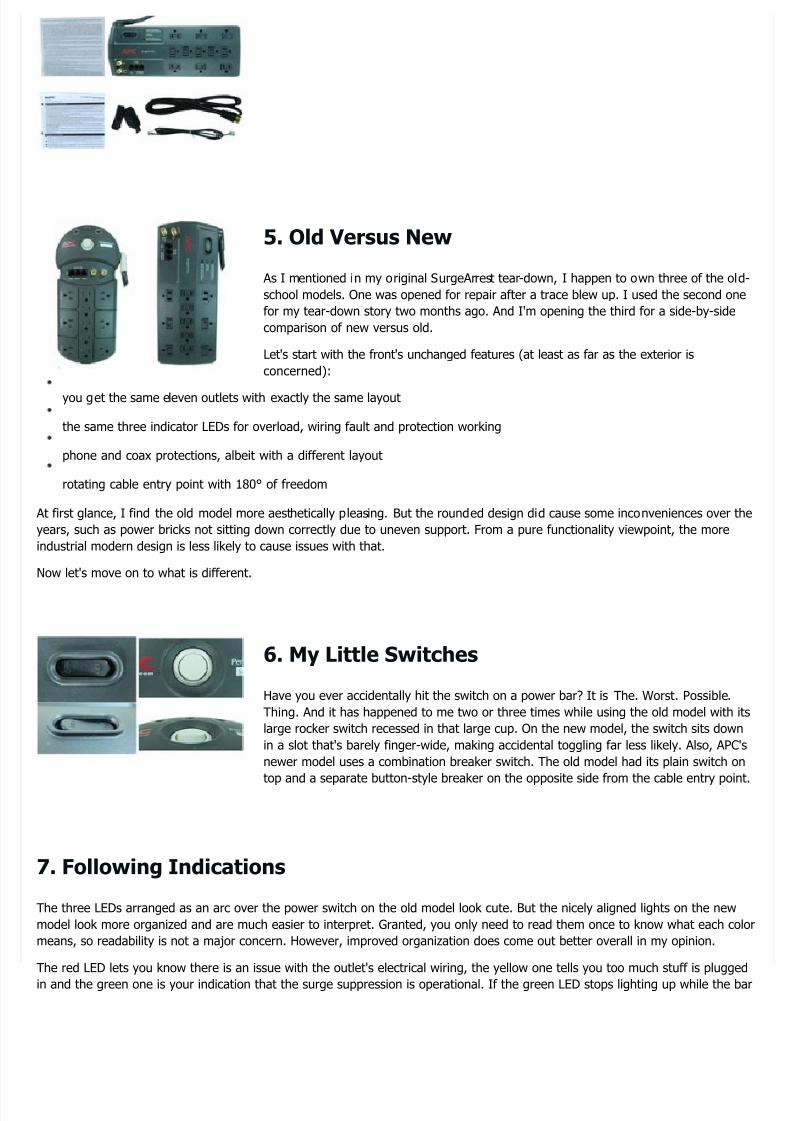
Have you ever accidentally hit the switch on a power bar It is The Worst Possible
Thing And it has happened to me two or three times while using the old model with it
large rocker switch recessed in that large cup On the new model the switch sits down
in a slot thats barely finger-wide making accidental toggling far less likely Also APC
newer model uses a combination breaker switch The old model had its plain switch on
top and a separate button-style breaker on the opposite side from the cable entry poin
The three LEDs arranged as an arc over the power switch on the old model look cute But the nicely aligned lights on the new
model look more organized and are much easier to interpret Granted you only need to read them once to know what each co
means so readability is not a major concern However improved organization does come out better overall in my opinion
The red LED lets you know there is an issue with the outlets electrical wiring the yellow one tells you too much stuff is plugge
in and the green one is your indication that the surge suppression is operational If the green LED stops lighting up while the b
7252019 APCs Current-Gen SurgeArrest_ A Modern Tear-Downpdf
httpslidepdfcomreaderfullapcs-current-gen-surgearrest-a-modern-tear-downpdf 38
8 The Outlets
9 The Black Labels
10 Barging In
is on it is your cue to cash in the lifetime replacement warranty
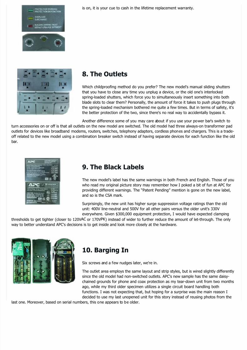
Which childproofing method do you prefer The new models manual sliding shutters
that you have to close any time you unplug a device or the old ones interlocked
spring-loaded shutters which force you to simultaneously insert something into both
blade slots to clear them Personally the amount of force it takes to push plugs throu
the spring-loaded mechanism bothered me quite a few times But in terms of safety it
the better protection of the two since theres no real way to accidentally bypass it
Another difference some of you may care about if you use your power bars switch toturn accessories on or off is that all outlets on the new model are switched The old model had three always-on transformer pad
outlets for devices like broadband modems routers switches telephony adapters cordless phones and chargers This is a trad
off related to the new model using a combination breaker switch instead of having separate devices for each function like the o
bar
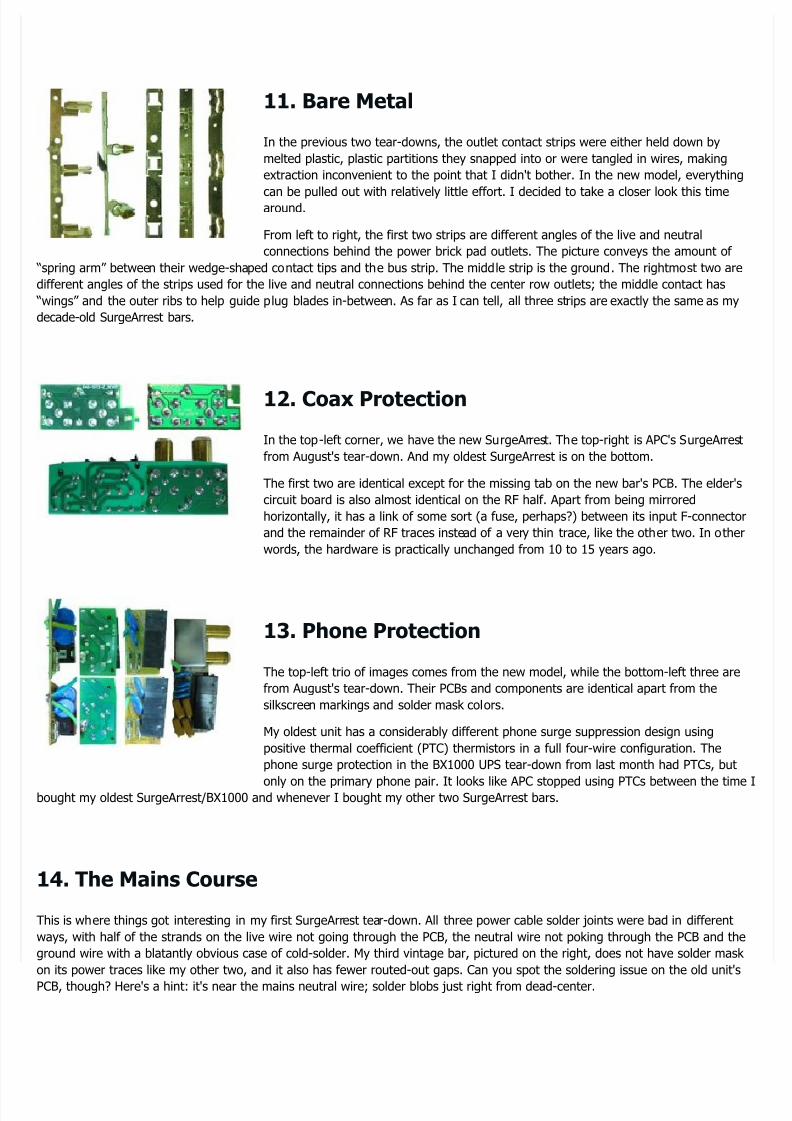
The new models label has the same warnings in both French and English Those of yo
who read my original picture story may remember how I poked a bit of fun at APC forproviding different warnings The ldquoPatent Pendingrdquo mention is gone on the new label
and so is the CSA mark
Surprisingly the new unit has higher surge suppression voltage ratings than the old
unit 400V line-neutral and 500V for all other pairs versus the older units 330V
everywhere Given $300000 equipment protection I would have expected clamping
thresholds to get tighter (closer to 120V AC or 170VPK ) instead of wider to further reduce the amount of let-through The only
way to better understand APCs decisions is to get inside and look more closely at the hardware
Six screws and a few nudges later were in
The outlet area employs the same layout and strip styles but is wired slightly different
since the old model had non-switched outlets APCs new sample has the same daisy-
chained grounds for phone and coax protection as my tear-down unit from two month
ago while my third older specimen utilizes a single circuit board handling both
functions I was not expecting that but hoping for a surprise was the main reason I
decided to use my last unopened unit for this story instead of reusing photos from the
last one Moreover based on serial numbers this one appears to be older
7252019 APCs Current-Gen SurgeArrest_ A Modern Tear-Downpdf
httpslidepdfcomreaderfullapcs-current-gen-surgearrest-a-modern-tear-downpdf 48
11 Bare Metal
12 Coax Protection
13 Phone Protection
14 The Mains Course
In the previous two tear-downs the outlet contact strips were either held down by
melted plastic plastic partitions they snapped into or were tangled in wires making
extraction inconvenient to the point that I didnt bother In the new model everything
can be pulled out with relatively little effort I decided to take a closer look this timearound
From left to right the first two strips are different angles of the live and neutral
connections behind the power brick pad outlets The picture conveys the amount of
ldquospring armrdquo between their wedge-shaped contact tips and the bus strip The middle strip is the ground The rightmost two are
different angles of the strips used for the live and neutral connections behind the center row outlets the middle contact has
ldquowingsrdquo and the outer ribs to help guide plug blades in-between As far as I can tell all three strips are exactly the same as my
decade-old SurgeArrest bars
In the top-left corner we have the new SurgeArrest The top-right is APCs SurgeArrest
from Augusts tear-down And my oldest SurgeArrest is on the bottom
The first two are identical except for the missing tab on the new bars PCB The elders
circuit board is also almost identical on the RF half Apart from being mirrored
horizontally it has a link of some sort (a fuse perhaps) between its input F-connecto
and the remainder of RF traces instead of a very thin trace like the other two In othe
words the hardware is practically unchanged from 10 to 15 years ago
The top-left trio of images comes from the new model while the bottom-left three are
from Augusts tear-down Their PCBs and components are identical apart from the
silkscreen markings and solder mask colors
My oldest unit has a considerably different phone surge suppression design using
positive thermal coefficient (PTC) thermistors in a full four-wire configuration The
phone surge protection in the BX1000 UPS tear-down from last month had PTCs but
only on the primary phone pair It looks like APC stopped using PTCs between the timbought my oldest SurgeArrestBX1000 and whenever I bought my other two SurgeArrest bars
This is where things got interesting in my first SurgeArrest tear-down All three power cable solder joints were bad in different
ways with half of the strands on the live wire not going through the PCB the neutral wire not poking through the PCB and the
ground wire with a blatantly obvious case of cold-solder My third vintage bar pictured on the right does not have solder mask
on its power traces like my other two and it also has fewer routed-out gaps Can you spot the soldering issue on the old units
PCB though Heres a hint its near the mains neutral wire solder blobs just right from dead-center
7252019 APCs Current-Gen SurgeArrest_ A Modern Tear-Downpdf
httpslidepdfcomreaderfullapcs-current-gen-surgearrest-a-modern-tear-downpdf 58
15 Not Quite Flawless
16 Forward To The Past
17 Better Than New
The new models PCB on the left is a little smaller with much shorter power traces
courtesy of the combination breaker switch APCs soldering job looks about as good a
it gets The large copper areas without solder mask are tin-plated instead of sporting a
solder coating But considering how wide and short the power traces are that extra ste
was likely unnecessary I would expect no less from any power bar over $30or any
cost for that matter considering the potential safety implications
Of course when you look hard enough to find something worth criticizing you usuall
find something Just to prove that I really scrutinized I found this on the ground wire
at the bottom the solder blob has a void in the middle of the wire strands Its not
ideal however considering how narrow the trace is thatll blow up long before
soldering becomes an issue
Unlike the old models where the outlet ground passed through the PCB the new
versions ground wire connects to the outlet ground strips first so the PCB only needsthe ground for wiring fault detection and occasional surges to ground making it far less critical Compared to what I found in
my oldest unit on the next page or in Augusts tear-down this is barely worth noting
This picture was taken from my third 10+-year-old SurgeArrest not the new unit The
new ones soldering is practically flawless
Remember that bit earlier about opening my oldest SurgeArrest for curiositys sake Itlooks like I have one more bar with bad solder joints for the records On the left next
the red arrow you can see that the solder and wire came apart when the wire got
trimmed indicating that the wire did not get hot enough for solder to bond properly
The rim around the wire with the purple arrows indicates that the solder bonding has
also failed along the circumference And the right side of the joint with the orange arrow simply has no solder on it Since this
one leg of the neutral-side inductor contact failure there would cause live mains voltage to show up on downstream ldquoneutralrdquo
wires becoming a shock hazard on non-grounded loads
On the plus side bad solder joints are usually very easy to fix Apply heat add solder i
necessary and to help with heat transfer reflow the whole pad and pinwire until solde
readily sticks to both Remove the heat and you should end up with a nice smooth an
shiny solder joint
With a thick copper wire and a large solder blob nearby getting the joint to reflow tak
a fair amount of heat This is likely why the original joint ended up uneven and
unbound The yellow-brown stuff is just solder flux nothing to worry about
Two out of three units purchased about a year apart requiring rework is not a good average Either I got extremely unlucky or
QA was not quite what it should have been back then
7252019 APCs Current-Gen SurgeArrest_ A Modern Tear-Downpdf
httpslidepdfcomreaderfullapcs-current-gen-surgearrest-a-modern-tear-downpdf 68
18 Flipping The Boards
19 Two Sides Of The Same Coin
20 Testing Testing
21 More Testing
Removing the standalone breaker and accommodations for the switched outlets freed
a fair amount of space enabling a less cluttered layout It looks like APC did not start
heat-shrinking MOVs to its thermal shutoff until some point after after my oldest bar w
purchased On the new one each ground-side MOV pair gets bundled with a thermalprotection instead of sharing one thermal fuse four ways The two lone devices are GN
20D471K and the others appear to be GNR 20D201K
Without reverse-engineering the two boards we can see that the type and count of
individual components is mostly unchanged the new model has one less MOV one extra thermal shutoff a much smaller 47nF
X-cap and a combination breaker switch Those appear to be the obvious parts list changes
With both sides next to each other we see the main thermal cut-off sandwiched
between the top two MOVs in series with the live wire and switch as expected One of
those MOVs goes from the fuse to the filtered neutral island in the middle (largest one)
while the other goes from filtered live to unfiltered neutral The horizontal un-fused MO
near the switch is directly across filtered live and neutral to catch what the other MOVs
do not
In the bottom-left corner of the component-side image we have the four live-ground
and line-ground MOVs with one MOV both before and after the inductors The inner two MOVs are across ground and mains
neutral the middle one connects to filtered neutral the fourth to unfiltered live and the outer MOV connects to filtered live I
really was not expecting this much snaking around with the MOV traces nor such narrow traces which are nothing like the old
bars fat solder-coated ones
Considering how narrow the MOV traces are compared to the surge currents that may
pass through them the circuit board etching process and the copper thickness need to
meet or exceed requirements with a high degree of confidence APC tests for this using
four-terminal ldquoKelvinrdquo resistance measurement across a very narrow sample If the copp
is too thin or the etch too aggressive this traces resistance will exceed the control
value The only multimeter I own goes down to 01Ω so I am two digits short of beinable to tell it is there if I tried measuring it
There are three pairs of middle-of-nowhere pads two along the main MOVs traces on the left and another along the ground pa
on the right I solder-wicked two of those small blobs to see if they may have been solder fuses but all I found underneath was
the trace going through I suspect those are additional test points much like the trace in the previous slide A Kelvin resistance
measurement works by applying a known constant current through a circuit (a trace in this case) and measuring the voltage drdirectly across the load (the piece of trace between test points) to calculate the loads
7252019 APCs Current-Gen SurgeArrest_ A Modern Tear-Downpdf
httpslidepdfcomreaderfullapcs-current-gen-surgearrest-a-modern-tear-downpdf 78
22 Metal Oxide Voyeurism
23 MOV Ratings On The Line
24 The MOV Connection
resistance without having to worry about voltage drop in the source wires This is why
Kelvin resistance measurement requires four wires
Remember a few slides ago when I was wondering why the new models protection ha
higher transient voltage ratings Prying shrink-wrapped MOVs revealed those I could
read this way to be GNR 20D201K just like the old models which were rated at 330V
Looks like the changes are simply a tweak in how they calculate and report ratings rath
than component swaps
Metal Oxide Varistors typically have four different voltage ratings
the nominal operating voltage below which the MOV does nothing
the varistor voltage at which the MOV current reaches 1mA DC ndash this is the rating that
ends up in the model number the 201 in 20D201K stands for 20x101 volts or about
200V
the clamping voltage when the MOV is conducting its nominal rated current and repeatable pulse energy which the MOV is
expected to be able to survive thousands of times if given a chance to cool down between pulses
sometimes the surge voltage when conducting its absolute maximum surge current which the MOV should be able to clam
but might not survive
In the GNR 20D201Ks case those would be 170VDC 205V 340V at 100A and 140 joules per pulse and unspecified surge
voltage at either 10kA one-shot or 65kA two-shots respectively This means connected equipment should not actually see muc
more than 340V unless the surge currents exceed 100A per MOV Perhaps a schematic would make that easier to see
If you had trouble imagining how those MOVs fit together based on my description ov
the last few slides here is a simplified picture of what I meant Orange circles highligh
20D201K MOVs sharing a thermal shut-off and the remaining two devices are
unprotected 20D471K The top two MOVs correspond to the pair shrink-tubed to the
live-side thermal fuse while the bottom four correspond to the two other heat-shrunk
MOV pairs and their respective thermal shut-off Crossing connections on the main MO
lets them leverage the inductors to dampen transients and reduce the burden on
individual devices
7252019 APCs Current-Gen SurgeArrest_ A Modern Tear-Downpdf
httpslidepdfcomreaderfullapcs-current-gen-surgearrest-a-modern-tear-downpdf 88
25 MOV Improvements
26 Less Is More
Since the MOVs have a combined nominal rating of about 15kJ other design considerations must be behind the packagings 3
claim Those likely include losses in the power cord voltage drop across the inductors and ldquoover-drivingrdquo the MOVs at the
expense of potentially shorter lifespan Since APC offers a lifetime warranty the company is obviously not expecting many
failures from this
For comparisons sake here is the simplified schematic of the old design As you cansee six out of the old models nine MOVs are located directly across mains lines where
they have to eat the brunt of mains-side transients with no help from inductors to softe
the blows
The new design may have one less MOV than the old design but they are being used
a more refined manner which should enhance their effectiveness
While the two models have nearly identical parts lists a more clever use of MOVs in th
new SurgeArrest should give it an advantage for surge protection The millimeter-wide
traces still bother me though
Aside from the loss of switched outlets and perhaps a regression in terms of aesthetics
would have to call the new model a winner in terms of functionality Its much less
accident-prone switch is quite welcome and the sliding outlet shutters are also less
troublesome to deal with when you do not really need or want them The boxier and
flatter design is also less likely to cause fitting issues and the more industrial look may appeal to fans of function over form
7252019 APCs Current-Gen SurgeArrest_ A Modern Tear-Downpdf
httpslidepdfcomreaderfullapcs-current-gen-surgearrest-a-modern-tear-downpdf 28
5 Old Versus New
6 My Little Switches
7 Following Indications
As I mentioned in my original SurgeArrest tear-down I happen to own three of the old
school models One was opened for repair after a trace blew up I used the second one
for my tear-down story two months ago And Im opening the third for a side-by-side
comparison of new versus old
Lets start with the fronts unchanged features (at least as far as the exterior is
concerned)
you get the same eleven outlets with exactly the same layout
the same three indicator LEDs for overload wiring fault and protection working
phone and coax protections albeit with a different layout
rotating cable entry point with 180deg of freedom
At first glance I find the old model more aesthetically pleasing But the rounded design did cause some inconveniences over th
years such as power bricks not sitting down correctly due to uneven support From a pure functionality viewpoint the more
industrial modern design is less likely to cause issues with that
Now lets move on to what is different
Have you ever accidentally hit the switch on a power bar It is The Worst Possible
Thing And it has happened to me two or three times while using the old model with it
large rocker switch recessed in that large cup On the new model the switch sits down
in a slot thats barely finger-wide making accidental toggling far less likely Also APC
newer model uses a combination breaker switch The old model had its plain switch on
top and a separate button-style breaker on the opposite side from the cable entry poin
The three LEDs arranged as an arc over the power switch on the old model look cute But the nicely aligned lights on the new
model look more organized and are much easier to interpret Granted you only need to read them once to know what each co
means so readability is not a major concern However improved organization does come out better overall in my opinion
The red LED lets you know there is an issue with the outlets electrical wiring the yellow one tells you too much stuff is plugge
in and the green one is your indication that the surge suppression is operational If the green LED stops lighting up while the b
7252019 APCs Current-Gen SurgeArrest_ A Modern Tear-Downpdf
httpslidepdfcomreaderfullapcs-current-gen-surgearrest-a-modern-tear-downpdf 38
8 The Outlets
9 The Black Labels
10 Barging In
is on it is your cue to cash in the lifetime replacement warranty
Which childproofing method do you prefer The new models manual sliding shutters
that you have to close any time you unplug a device or the old ones interlocked
spring-loaded shutters which force you to simultaneously insert something into both
blade slots to clear them Personally the amount of force it takes to push plugs throu
the spring-loaded mechanism bothered me quite a few times But in terms of safety it
the better protection of the two since theres no real way to accidentally bypass it
Another difference some of you may care about if you use your power bars switch toturn accessories on or off is that all outlets on the new model are switched The old model had three always-on transformer pad
outlets for devices like broadband modems routers switches telephony adapters cordless phones and chargers This is a trad
off related to the new model using a combination breaker switch instead of having separate devices for each function like the o
bar
The new models label has the same warnings in both French and English Those of yo
who read my original picture story may remember how I poked a bit of fun at APC forproviding different warnings The ldquoPatent Pendingrdquo mention is gone on the new label
and so is the CSA mark
Surprisingly the new unit has higher surge suppression voltage ratings than the old
unit 400V line-neutral and 500V for all other pairs versus the older units 330V
everywhere Given $300000 equipment protection I would have expected clamping
thresholds to get tighter (closer to 120V AC or 170VPK ) instead of wider to further reduce the amount of let-through The only
way to better understand APCs decisions is to get inside and look more closely at the hardware
Six screws and a few nudges later were in
The outlet area employs the same layout and strip styles but is wired slightly different
since the old model had non-switched outlets APCs new sample has the same daisy-
chained grounds for phone and coax protection as my tear-down unit from two month
ago while my third older specimen utilizes a single circuit board handling both
functions I was not expecting that but hoping for a surprise was the main reason I
decided to use my last unopened unit for this story instead of reusing photos from the
last one Moreover based on serial numbers this one appears to be older
7252019 APCs Current-Gen SurgeArrest_ A Modern Tear-Downpdf
httpslidepdfcomreaderfullapcs-current-gen-surgearrest-a-modern-tear-downpdf 48
11 Bare Metal
12 Coax Protection
13 Phone Protection
14 The Mains Course
In the previous two tear-downs the outlet contact strips were either held down by
melted plastic plastic partitions they snapped into or were tangled in wires making
extraction inconvenient to the point that I didnt bother In the new model everything
can be pulled out with relatively little effort I decided to take a closer look this timearound
From left to right the first two strips are different angles of the live and neutral
connections behind the power brick pad outlets The picture conveys the amount of
ldquospring armrdquo between their wedge-shaped contact tips and the bus strip The middle strip is the ground The rightmost two are
different angles of the strips used for the live and neutral connections behind the center row outlets the middle contact has
ldquowingsrdquo and the outer ribs to help guide plug blades in-between As far as I can tell all three strips are exactly the same as my
decade-old SurgeArrest bars
In the top-left corner we have the new SurgeArrest The top-right is APCs SurgeArrest
from Augusts tear-down And my oldest SurgeArrest is on the bottom
The first two are identical except for the missing tab on the new bars PCB The elders
circuit board is also almost identical on the RF half Apart from being mirrored
horizontally it has a link of some sort (a fuse perhaps) between its input F-connecto
and the remainder of RF traces instead of a very thin trace like the other two In othe
words the hardware is practically unchanged from 10 to 15 years ago
The top-left trio of images comes from the new model while the bottom-left three are
from Augusts tear-down Their PCBs and components are identical apart from the
silkscreen markings and solder mask colors
My oldest unit has a considerably different phone surge suppression design using
positive thermal coefficient (PTC) thermistors in a full four-wire configuration The
phone surge protection in the BX1000 UPS tear-down from last month had PTCs but
only on the primary phone pair It looks like APC stopped using PTCs between the timbought my oldest SurgeArrestBX1000 and whenever I bought my other two SurgeArrest bars
This is where things got interesting in my first SurgeArrest tear-down All three power cable solder joints were bad in different
ways with half of the strands on the live wire not going through the PCB the neutral wire not poking through the PCB and the
ground wire with a blatantly obvious case of cold-solder My third vintage bar pictured on the right does not have solder mask
on its power traces like my other two and it also has fewer routed-out gaps Can you spot the soldering issue on the old units
PCB though Heres a hint its near the mains neutral wire solder blobs just right from dead-center
7252019 APCs Current-Gen SurgeArrest_ A Modern Tear-Downpdf
httpslidepdfcomreaderfullapcs-current-gen-surgearrest-a-modern-tear-downpdf 58
15 Not Quite Flawless
16 Forward To The Past
17 Better Than New
The new models PCB on the left is a little smaller with much shorter power traces
courtesy of the combination breaker switch APCs soldering job looks about as good a
it gets The large copper areas without solder mask are tin-plated instead of sporting a
solder coating But considering how wide and short the power traces are that extra ste
was likely unnecessary I would expect no less from any power bar over $30or any
cost for that matter considering the potential safety implications
Of course when you look hard enough to find something worth criticizing you usuall
find something Just to prove that I really scrutinized I found this on the ground wire
at the bottom the solder blob has a void in the middle of the wire strands Its not
ideal however considering how narrow the trace is thatll blow up long before
soldering becomes an issue
Unlike the old models where the outlet ground passed through the PCB the new
versions ground wire connects to the outlet ground strips first so the PCB only needsthe ground for wiring fault detection and occasional surges to ground making it far less critical Compared to what I found in
my oldest unit on the next page or in Augusts tear-down this is barely worth noting
This picture was taken from my third 10+-year-old SurgeArrest not the new unit The
new ones soldering is practically flawless
Remember that bit earlier about opening my oldest SurgeArrest for curiositys sake Itlooks like I have one more bar with bad solder joints for the records On the left next
the red arrow you can see that the solder and wire came apart when the wire got
trimmed indicating that the wire did not get hot enough for solder to bond properly
The rim around the wire with the purple arrows indicates that the solder bonding has
also failed along the circumference And the right side of the joint with the orange arrow simply has no solder on it Since this
one leg of the neutral-side inductor contact failure there would cause live mains voltage to show up on downstream ldquoneutralrdquo
wires becoming a shock hazard on non-grounded loads
On the plus side bad solder joints are usually very easy to fix Apply heat add solder i
necessary and to help with heat transfer reflow the whole pad and pinwire until solde
readily sticks to both Remove the heat and you should end up with a nice smooth an
shiny solder joint
With a thick copper wire and a large solder blob nearby getting the joint to reflow tak
a fair amount of heat This is likely why the original joint ended up uneven and
unbound The yellow-brown stuff is just solder flux nothing to worry about
Two out of three units purchased about a year apart requiring rework is not a good average Either I got extremely unlucky or
QA was not quite what it should have been back then
7252019 APCs Current-Gen SurgeArrest_ A Modern Tear-Downpdf
httpslidepdfcomreaderfullapcs-current-gen-surgearrest-a-modern-tear-downpdf 68
18 Flipping The Boards
19 Two Sides Of The Same Coin
20 Testing Testing
21 More Testing
Removing the standalone breaker and accommodations for the switched outlets freed
a fair amount of space enabling a less cluttered layout It looks like APC did not start
heat-shrinking MOVs to its thermal shutoff until some point after after my oldest bar w
purchased On the new one each ground-side MOV pair gets bundled with a thermalprotection instead of sharing one thermal fuse four ways The two lone devices are GN
20D471K and the others appear to be GNR 20D201K
Without reverse-engineering the two boards we can see that the type and count of
individual components is mostly unchanged the new model has one less MOV one extra thermal shutoff a much smaller 47nF
X-cap and a combination breaker switch Those appear to be the obvious parts list changes
With both sides next to each other we see the main thermal cut-off sandwiched
between the top two MOVs in series with the live wire and switch as expected One of
those MOVs goes from the fuse to the filtered neutral island in the middle (largest one)
while the other goes from filtered live to unfiltered neutral The horizontal un-fused MO
near the switch is directly across filtered live and neutral to catch what the other MOVs
do not
In the bottom-left corner of the component-side image we have the four live-ground
and line-ground MOVs with one MOV both before and after the inductors The inner two MOVs are across ground and mains
neutral the middle one connects to filtered neutral the fourth to unfiltered live and the outer MOV connects to filtered live I
really was not expecting this much snaking around with the MOV traces nor such narrow traces which are nothing like the old
bars fat solder-coated ones
Considering how narrow the MOV traces are compared to the surge currents that may
pass through them the circuit board etching process and the copper thickness need to
meet or exceed requirements with a high degree of confidence APC tests for this using
four-terminal ldquoKelvinrdquo resistance measurement across a very narrow sample If the copp
is too thin or the etch too aggressive this traces resistance will exceed the control
value The only multimeter I own goes down to 01Ω so I am two digits short of beinable to tell it is there if I tried measuring it
There are three pairs of middle-of-nowhere pads two along the main MOVs traces on the left and another along the ground pa
on the right I solder-wicked two of those small blobs to see if they may have been solder fuses but all I found underneath was
the trace going through I suspect those are additional test points much like the trace in the previous slide A Kelvin resistance
measurement works by applying a known constant current through a circuit (a trace in this case) and measuring the voltage drdirectly across the load (the piece of trace between test points) to calculate the loads
7252019 APCs Current-Gen SurgeArrest_ A Modern Tear-Downpdf
httpslidepdfcomreaderfullapcs-current-gen-surgearrest-a-modern-tear-downpdf 78
22 Metal Oxide Voyeurism
23 MOV Ratings On The Line
24 The MOV Connection
resistance without having to worry about voltage drop in the source wires This is why
Kelvin resistance measurement requires four wires
Remember a few slides ago when I was wondering why the new models protection ha
higher transient voltage ratings Prying shrink-wrapped MOVs revealed those I could
read this way to be GNR 20D201K just like the old models which were rated at 330V
Looks like the changes are simply a tweak in how they calculate and report ratings rath
than component swaps
Metal Oxide Varistors typically have four different voltage ratings
the nominal operating voltage below which the MOV does nothing
the varistor voltage at which the MOV current reaches 1mA DC ndash this is the rating that
ends up in the model number the 201 in 20D201K stands for 20x101 volts or about
200V
the clamping voltage when the MOV is conducting its nominal rated current and repeatable pulse energy which the MOV is
expected to be able to survive thousands of times if given a chance to cool down between pulses
sometimes the surge voltage when conducting its absolute maximum surge current which the MOV should be able to clam
but might not survive
In the GNR 20D201Ks case those would be 170VDC 205V 340V at 100A and 140 joules per pulse and unspecified surge
voltage at either 10kA one-shot or 65kA two-shots respectively This means connected equipment should not actually see muc
more than 340V unless the surge currents exceed 100A per MOV Perhaps a schematic would make that easier to see
If you had trouble imagining how those MOVs fit together based on my description ov
the last few slides here is a simplified picture of what I meant Orange circles highligh
20D201K MOVs sharing a thermal shut-off and the remaining two devices are
unprotected 20D471K The top two MOVs correspond to the pair shrink-tubed to the
live-side thermal fuse while the bottom four correspond to the two other heat-shrunk
MOV pairs and their respective thermal shut-off Crossing connections on the main MO
lets them leverage the inductors to dampen transients and reduce the burden on
individual devices
7252019 APCs Current-Gen SurgeArrest_ A Modern Tear-Downpdf
httpslidepdfcomreaderfullapcs-current-gen-surgearrest-a-modern-tear-downpdf 88
25 MOV Improvements
26 Less Is More
Since the MOVs have a combined nominal rating of about 15kJ other design considerations must be behind the packagings 3
claim Those likely include losses in the power cord voltage drop across the inductors and ldquoover-drivingrdquo the MOVs at the
expense of potentially shorter lifespan Since APC offers a lifetime warranty the company is obviously not expecting many
failures from this
For comparisons sake here is the simplified schematic of the old design As you cansee six out of the old models nine MOVs are located directly across mains lines where
they have to eat the brunt of mains-side transients with no help from inductors to softe
the blows
The new design may have one less MOV than the old design but they are being used
a more refined manner which should enhance their effectiveness
While the two models have nearly identical parts lists a more clever use of MOVs in th
new SurgeArrest should give it an advantage for surge protection The millimeter-wide
traces still bother me though
Aside from the loss of switched outlets and perhaps a regression in terms of aesthetics
would have to call the new model a winner in terms of functionality Its much less
accident-prone switch is quite welcome and the sliding outlet shutters are also less
troublesome to deal with when you do not really need or want them The boxier and
flatter design is also less likely to cause fitting issues and the more industrial look may appeal to fans of function over form
7252019 APCs Current-Gen SurgeArrest_ A Modern Tear-Downpdf
httpslidepdfcomreaderfullapcs-current-gen-surgearrest-a-modern-tear-downpdf 48
11 Bare Metal
12 Coax Protection
13 Phone Protection
14 The Mains Course
In the previous two tear-downs the outlet contact strips were either held down by
melted plastic plastic partitions they snapped into or were tangled in wires making
extraction inconvenient to the point that I didnt bother In the new model everything
can be pulled out with relatively little effort I decided to take a closer look this timearound
From left to right the first two strips are different angles of the live and neutral
connections behind the power brick pad outlets The picture conveys the amount of
ldquospring armrdquo between their wedge-shaped contact tips and the bus strip The middle strip is the ground The rightmost two are
different angles of the strips used for the live and neutral connections behind the center row outlets the middle contact has
ldquowingsrdquo and the outer ribs to help guide plug blades in-between As far as I can tell all three strips are exactly the same as my
decade-old SurgeArrest bars
In the top-left corner we have the new SurgeArrest The top-right is APCs SurgeArrest
from Augusts tear-down And my oldest SurgeArrest is on the bottom
The first two are identical except for the missing tab on the new bars PCB The elders
circuit board is also almost identical on the RF half Apart from being mirrored
horizontally it has a link of some sort (a fuse perhaps) between its input F-connecto
and the remainder of RF traces instead of a very thin trace like the other two In othe
words the hardware is practically unchanged from 10 to 15 years ago
The top-left trio of images comes from the new model while the bottom-left three are
from Augusts tear-down Their PCBs and components are identical apart from the
silkscreen markings and solder mask colors
My oldest unit has a considerably different phone surge suppression design using
positive thermal coefficient (PTC) thermistors in a full four-wire configuration The
phone surge protection in the BX1000 UPS tear-down from last month had PTCs but
only on the primary phone pair It looks like APC stopped using PTCs between the timbought my oldest SurgeArrestBX1000 and whenever I bought my other two SurgeArrest bars
This is where things got interesting in my first SurgeArrest tear-down All three power cable solder joints were bad in different
ways with half of the strands on the live wire not going through the PCB the neutral wire not poking through the PCB and the
ground wire with a blatantly obvious case of cold-solder My third vintage bar pictured on the right does not have solder mask
on its power traces like my other two and it also has fewer routed-out gaps Can you spot the soldering issue on the old units
PCB though Heres a hint its near the mains neutral wire solder blobs just right from dead-center
7252019 APCs Current-Gen SurgeArrest_ A Modern Tear-Downpdf
httpslidepdfcomreaderfullapcs-current-gen-surgearrest-a-modern-tear-downpdf 58
15 Not Quite Flawless
16 Forward To The Past
17 Better Than New
The new models PCB on the left is a little smaller with much shorter power traces
courtesy of the combination breaker switch APCs soldering job looks about as good a
it gets The large copper areas without solder mask are tin-plated instead of sporting a
solder coating But considering how wide and short the power traces are that extra ste
was likely unnecessary I would expect no less from any power bar over $30or any
cost for that matter considering the potential safety implications
Of course when you look hard enough to find something worth criticizing you usuall
find something Just to prove that I really scrutinized I found this on the ground wire
at the bottom the solder blob has a void in the middle of the wire strands Its not
ideal however considering how narrow the trace is thatll blow up long before
soldering becomes an issue
Unlike the old models where the outlet ground passed through the PCB the new
versions ground wire connects to the outlet ground strips first so the PCB only needsthe ground for wiring fault detection and occasional surges to ground making it far less critical Compared to what I found in
my oldest unit on the next page or in Augusts tear-down this is barely worth noting
This picture was taken from my third 10+-year-old SurgeArrest not the new unit The
new ones soldering is practically flawless
Remember that bit earlier about opening my oldest SurgeArrest for curiositys sake Itlooks like I have one more bar with bad solder joints for the records On the left next
the red arrow you can see that the solder and wire came apart when the wire got
trimmed indicating that the wire did not get hot enough for solder to bond properly
The rim around the wire with the purple arrows indicates that the solder bonding has
also failed along the circumference And the right side of the joint with the orange arrow simply has no solder on it Since this
one leg of the neutral-side inductor contact failure there would cause live mains voltage to show up on downstream ldquoneutralrdquo
wires becoming a shock hazard on non-grounded loads
On the plus side bad solder joints are usually very easy to fix Apply heat add solder i
necessary and to help with heat transfer reflow the whole pad and pinwire until solde
readily sticks to both Remove the heat and you should end up with a nice smooth an
shiny solder joint
With a thick copper wire and a large solder blob nearby getting the joint to reflow tak
a fair amount of heat This is likely why the original joint ended up uneven and
unbound The yellow-brown stuff is just solder flux nothing to worry about
Two out of three units purchased about a year apart requiring rework is not a good average Either I got extremely unlucky or
QA was not quite what it should have been back then
7252019 APCs Current-Gen SurgeArrest_ A Modern Tear-Downpdf
httpslidepdfcomreaderfullapcs-current-gen-surgearrest-a-modern-tear-downpdf 68
18 Flipping The Boards
19 Two Sides Of The Same Coin
20 Testing Testing
21 More Testing
Removing the standalone breaker and accommodations for the switched outlets freed
a fair amount of space enabling a less cluttered layout It looks like APC did not start
heat-shrinking MOVs to its thermal shutoff until some point after after my oldest bar w
purchased On the new one each ground-side MOV pair gets bundled with a thermalprotection instead of sharing one thermal fuse four ways The two lone devices are GN
20D471K and the others appear to be GNR 20D201K
Without reverse-engineering the two boards we can see that the type and count of
individual components is mostly unchanged the new model has one less MOV one extra thermal shutoff a much smaller 47nF
X-cap and a combination breaker switch Those appear to be the obvious parts list changes
With both sides next to each other we see the main thermal cut-off sandwiched
between the top two MOVs in series with the live wire and switch as expected One of
those MOVs goes from the fuse to the filtered neutral island in the middle (largest one)
while the other goes from filtered live to unfiltered neutral The horizontal un-fused MO
near the switch is directly across filtered live and neutral to catch what the other MOVs
do not
In the bottom-left corner of the component-side image we have the four live-ground
and line-ground MOVs with one MOV both before and after the inductors The inner two MOVs are across ground and mains
neutral the middle one connects to filtered neutral the fourth to unfiltered live and the outer MOV connects to filtered live I
really was not expecting this much snaking around with the MOV traces nor such narrow traces which are nothing like the old
bars fat solder-coated ones
Considering how narrow the MOV traces are compared to the surge currents that may
pass through them the circuit board etching process and the copper thickness need to
meet or exceed requirements with a high degree of confidence APC tests for this using
four-terminal ldquoKelvinrdquo resistance measurement across a very narrow sample If the copp
is too thin or the etch too aggressive this traces resistance will exceed the control
value The only multimeter I own goes down to 01Ω so I am two digits short of beinable to tell it is there if I tried measuring it
There are three pairs of middle-of-nowhere pads two along the main MOVs traces on the left and another along the ground pa
on the right I solder-wicked two of those small blobs to see if they may have been solder fuses but all I found underneath was
the trace going through I suspect those are additional test points much like the trace in the previous slide A Kelvin resistance
measurement works by applying a known constant current through a circuit (a trace in this case) and measuring the voltage drdirectly across the load (the piece of trace between test points) to calculate the loads
7252019 APCs Current-Gen SurgeArrest_ A Modern Tear-Downpdf
httpslidepdfcomreaderfullapcs-current-gen-surgearrest-a-modern-tear-downpdf 78
22 Metal Oxide Voyeurism
23 MOV Ratings On The Line
24 The MOV Connection
resistance without having to worry about voltage drop in the source wires This is why
Kelvin resistance measurement requires four wires
Remember a few slides ago when I was wondering why the new models protection ha
higher transient voltage ratings Prying shrink-wrapped MOVs revealed those I could
read this way to be GNR 20D201K just like the old models which were rated at 330V
Looks like the changes are simply a tweak in how they calculate and report ratings rath
than component swaps
Metal Oxide Varistors typically have four different voltage ratings
the nominal operating voltage below which the MOV does nothing
the varistor voltage at which the MOV current reaches 1mA DC ndash this is the rating that
ends up in the model number the 201 in 20D201K stands for 20x101 volts or about
200V
the clamping voltage when the MOV is conducting its nominal rated current and repeatable pulse energy which the MOV is
expected to be able to survive thousands of times if given a chance to cool down between pulses
sometimes the surge voltage when conducting its absolute maximum surge current which the MOV should be able to clam
but might not survive
In the GNR 20D201Ks case those would be 170VDC 205V 340V at 100A and 140 joules per pulse and unspecified surge
voltage at either 10kA one-shot or 65kA two-shots respectively This means connected equipment should not actually see muc
more than 340V unless the surge currents exceed 100A per MOV Perhaps a schematic would make that easier to see
If you had trouble imagining how those MOVs fit together based on my description ov
the last few slides here is a simplified picture of what I meant Orange circles highligh
20D201K MOVs sharing a thermal shut-off and the remaining two devices are
unprotected 20D471K The top two MOVs correspond to the pair shrink-tubed to the
live-side thermal fuse while the bottom four correspond to the two other heat-shrunk
MOV pairs and their respective thermal shut-off Crossing connections on the main MO
lets them leverage the inductors to dampen transients and reduce the burden on
individual devices
7252019 APCs Current-Gen SurgeArrest_ A Modern Tear-Downpdf
httpslidepdfcomreaderfullapcs-current-gen-surgearrest-a-modern-tear-downpdf 88
25 MOV Improvements
26 Less Is More
Since the MOVs have a combined nominal rating of about 15kJ other design considerations must be behind the packagings 3
claim Those likely include losses in the power cord voltage drop across the inductors and ldquoover-drivingrdquo the MOVs at the
expense of potentially shorter lifespan Since APC offers a lifetime warranty the company is obviously not expecting many
failures from this
For comparisons sake here is the simplified schematic of the old design As you cansee six out of the old models nine MOVs are located directly across mains lines where
they have to eat the brunt of mains-side transients with no help from inductors to softe
the blows
The new design may have one less MOV than the old design but they are being used
a more refined manner which should enhance their effectiveness
While the two models have nearly identical parts lists a more clever use of MOVs in th
new SurgeArrest should give it an advantage for surge protection The millimeter-wide
traces still bother me though
Aside from the loss of switched outlets and perhaps a regression in terms of aesthetics
would have to call the new model a winner in terms of functionality Its much less
accident-prone switch is quite welcome and the sliding outlet shutters are also less
troublesome to deal with when you do not really need or want them The boxier and
flatter design is also less likely to cause fitting issues and the more industrial look may appeal to fans of function over form

7252019 APCs Current-Gen SurgeArrest_ A Modern Tear-Downpdf
httpslidepdfcomreaderfullapcs-current-gen-surgearrest-a-modern-tear-downpdf 88
25 MOV Improvements
26 Less Is More
Since the MOVs have a combined nominal rating of about 15kJ other design considerations must be behind the packagings 3
claim Those likely include losses in the power cord voltage drop across the inductors and ldquoover-drivingrdquo the MOVs at the
expense of potentially shorter lifespan Since APC offers a lifetime warranty the company is obviously not expecting many
failures from this
For comparisons sake here is the simplified schematic of the old design As you cansee six out of the old models nine MOVs are located directly across mains lines where
they have to eat the brunt of mains-side transients with no help from inductors to softe
the blows
The new design may have one less MOV than the old design but they are being used
a more refined manner which should enhance their effectiveness
While the two models have nearly identical parts lists a more clever use of MOVs in th
new SurgeArrest should give it an advantage for surge protection The millimeter-wide
traces still bother me though
Aside from the loss of switched outlets and perhaps a regression in terms of aesthetics
would have to call the new model a winner in terms of functionality Its much less
accident-prone switch is quite welcome and the sliding outlet shutters are also less
troublesome to deal with when you do not really need or want them The boxier and
flatter design is also less likely to cause fitting issues and the more industrial look may appeal to fans of function over form


![10[1]osteopatia e down.pdf](https://img.pdfslide.net/doc/110x75/55cf9dfd550346d033b02b33/101osteopatia-e-downpdf.jpg)