Embed Size (px)
Citation preview
APCUPSD User Manual
http://www.apcupsd.com/manual/manual.html#installation-serial-line-upses[5/9/2014 1:39:41 PM]
APCUPSD User ManualAdam KropelinKern Sibbald
Apcupsd is a UPS control system that permits orderly shutdown of your computer in the eventof a power failure.
March 28, 2014 23:31:49This manual documents apcupsd version 3.14.xCopyright © 2004-2014 Adam KropelinCopyright © 1999-2005 Kern Sibbald
Copying and distribution of this file, with or without modification, are permitted in any medium withoutroyalty provided the name Apcupsd, the copyright notice, and this notice are preserved.
Apcupsd source code is released under the GNU General Public License version 2. Please see the fileCOPYING in the main source directory.
For more information on the project, please visit the main web site at http://www.apcupsd.com
Table of Contents
Important Legal DisclaimerHow To Use This ManualBasic User's Guide
Quick Start for BeginnersSupported Operating Systems
Platform SupportSupported UPSes and CablesChoosing a Configuration TypeConfiguration types
USB ConfigurationLinux USB Configuration
Known Linux USB IssuesVerifying Device Detection and DriverDevice NodesMiscellaneous
BSD USB ConfigurationKnown BSD USB IssuesPlatforms and VersionsKernel ConfigurationVerifying Device Detection and DriverDevice Nodes
Windows USB ConfigurationPlatforms and VersionsUSB Driver InstallationVerifying Device Detection and Driver
Solaris USB ConfigurationPlatforms and VersionsBuilding Apcupsd with USB
APCUPSD User Manual
http://www.apcupsd.com/manual/manual.html#installation-serial-line-upses[5/9/2014 1:39:41 PM]
Verifying Device Detection and DriverDevice Nodes
Mac OS X (Darwin) USB ConfigurationPlatforms and VersionsBuilding Apcupsd with USBVerifying Device Detection and Driver
Building and Installing apcupsdInstallation from Binary Packages
RPMSMicrosoft Windows
Installation from SourceVerifying a Source InstallationConfigure OptionsRecommended Options for most SystemsCompilers and OptionsOperating System Specifics
DebianFreeBSDHPUXNetBSDMac OS X DarwinOpenBSDRed Hat SystemsSlackwareSUSESun SolarisUnknown SystemWindows Systems
After InstallationChecking Your Configuration FileArranging for Reboot on Power-UpMaking sure apcupsd Is Running
Configuration ExamplesA Simple USB ConfigurationA Simple Configuration for a Serial SmartUPSA Simple Configuration for a Simple Signaling or DumbNIS Server/Client Configuration Using the Net Driver
Differences between NIS Client/Server and the old (now removed) Master/Slavemodes
PowerChute Network Shutdown Driver (PCNET)MODBUS Driver
Testing ApcupsdProcess-Status TestLogging Testapcaccess TestCommunications TestSimulated Power Fail TestSystem Shutdown TestFull Power Down Testapctest
Monitoring and Tuning your UPSapcaccessApcupsd Notification and Eventsapcupsd Network Monitoring (CGI) Programs
Setting up and Testing the CGI ProgramsUsing the CGI Programs on Windowsmultimon.cgi
APCUPSD User Manual
http://www.apcupsd.com/manual/manual.html#installation-serial-line-upses[5/9/2014 1:39:41 PM]
upsstats.cgiupsfstatus.cgiA Tip from Carl Erhorn for Sun Systems:CGI Credits
Security Issues:Firewall SettingsTCP Wrappers
Configuring Your EEPROMUsing apctest to Configure Your EEPROM
Maintaining Your UPS BatteriesBattery TechnologyBattery LifeFlashing Battery Charge Graph LEDsBattery ReplacementBattery Installation"Soft" Runtime Calibration"Manual" Runtime CalibrationResetting the UPS Battery Constant
Frequently-Asked QuestionsCustomizing Event Handling
apccontrol Command Line OptionsControlling Multiple UPSes on one Machine
Multiple UPS ExampleSupport for SNMP UPSes
Planning and Setup for SNMP WiringPlanning and Setup for SNMP Configuration
Assign SNMP Card IP AddressSet SNMP card General ParametersSet SNMP card Shutdown ParametersConfigure Event Trap Receivers
Connecting APCUPSD to a SNMP UPSBuilding with SNMP supportSNMP Trap CatchingKnown Problems
apcupsd System LoggingLogging Types
Data LoggingStatus LoggingEVENTS Logging
Implementation DetailsThe Windows Version of apcupsd
Installing Apcupsd on WindowsConfiguring Apcupsd on WindowsStarting Apcupsd on WindowsApctrayTesting Apcupsd on WindowsUpgradingPost-InstallationProblem AreasEmail Notification of EventsKillpower under WindowsPower Down During ShutdownCommand Line Options Specific to the Windows Version
Installation: Serial-Line UPSesOverview of Serial-Interface UPSesConnecting a Serial-Line UPS to a USB PortTesting Serial-Line UPSes
APCUPSD User Manual
http://www.apcupsd.com/manual/manual.html#installation-serial-line-upses[5/9/2014 1:39:41 PM]
Establishing Serial Port ConnectionOnce you have established serial communicationsTroubleshooting Serial Line communications
Bizarre Intermittent Behavior:Cables
Smart-Custom Cable for SmartUPSesSimple-Custom Voltage-Signalling Cable for "dumb" UPSesCustom-RJ45 Smart Signalling Cable for BackUPS CS ModelsOther APC Cables that apcupsd SupportsVoltage Signalling Features Supported by Apcupsd for Various CablesVoltage SignallingThe Back-UPS Office 500 signalsAnalyses of APC Cables
940-0020B Cable Wiring940-0020C Cable Wiring940-0023A Cable Wiring940-0024C Cable Wiring940-0095A Cable Wiring940-0095B Cable Wiring940-0119A Cable WiringSerial BackUPS ES Wiring940-0128A Cable Wiring940-0128D Cable Wiring940-0127B Cable Wiring
Win32 Implementation Restrictions for Simple UPSesInternal Apcupsd Actions for Simple Cables
Recalibrating the UPS RuntimeConfiguration Directive Reference
General Configuration DirectivesConfiguration Directives Used by the Network Information ServerConfiguration Directives used during Power FailuresConfiguration Directives used to Control System LoggingConfiguration Directives for Sharing a UPSConfiguration Directives Used to Set the UPS EEPROM
apcupsd Status LoggingStatus report formatStatus Report ExampleStatus Report FieldsLogging the STATUS Information
The Shutdown Sequence and its DiscontentsShutdown SequenceShutdown ProblemsMaster/Slave ShutdownStartupWindows Considerations
APC smart protocolDescriptionRS-232 differencesThe Smart ProtocolDip switch infoStatus bitsAlert messagesRegister 1Register 2Register 3Interpretation of the Old Firmware RevisionInterpretation of the New Firmware Revision
APCUPSD User Manual
http://www.apcupsd.com/manual/manual.html#installation-serial-line-upses[5/9/2014 1:39:41 PM]
EEPROM ValuesProgramming the UPS EEPROM
NIS Network Server ProtocolApcupsd RPM Packaging FAQCredits
Contributors
Important Legal DisclaimerNo person should rely on the contents of the APCUPSD Manual ("the manual") without first obtaining advicefrom APC Technical Support.
The manual is provided on the terms and understanding that:
1. the authors, contributors and editors are not responsible for the results of any actionstaken on the basis of information in the manual, nor for any error in or omission from themanual; and
2. the authors, contributors and editors are not engaged in rendering technical or otheradvice or services.
The the authors, contributors and editors, expressly disclaim all and any liability and responsibility to anyperson, whether a reader of the manual or not, in respect of anything, and of the consequences ofanything, done or omitted to be done by any such person in reliance, whether wholly or partially, on thewhole or any part of the contents of the manual. Without limiting the generality of the above, no author,contributor or editor shall have any responsibility for any act or omission of any other author, contributor oreditor.
How To Use This ManualThis is the manual for apcupsd, a daemon for communicating with UPSes (Uninterruptible Power Supplies)made by American Power Conversion Corporation (APC). If you have an APC-made UPS, whether soldunder the APC nameplate or OEMed (for example, the HP PowerTrust 2997A), and you want you get itworking with a computer running Linux, Unix, or Windows, you are reading the right document.
This manual is divided into parts which increase in technical depth as they go. If you have just bought astate-of-the-art smart UPS with a USB or Ethernet interface, and you are running a current version of RedHat or SUSE Linux, then apcupsd is very nearly plug-and-play and you will have to read only the BasicUser's Guide.
If your operating system is older, or if you have an old-fashioned serial-line UPS, you'll have to read aboutserial installation (see Installation: Serial-Line UPSes). If you need more details about administration forunusual situations (such as a master/slave or multi-UPS setup) you'll need to read the sections on thosetopics as well. Finally, there are a number of technical reference sections which gives full details on thingslike configuration file directives and event-logging formats.
You should begin by reading the Quick Start (see Quick Start for Beginners) instructions.
Basic User's GuideQuick Start for Beginners
apcupsd is a complex piece of software, but most of its complexities are meant for dealing with older
APCUPSD User Manual
http://www.apcupsd.com/manual/manual.html#installation-serial-line-upses[5/9/2014 1:39:41 PM]
hardware and operating systems. On current hardware and software getting it running should not be verycomplicated.
The following is a help guide to the steps needed to get apcupsd set up and running as painlessly aspossible.
1. Check to see if apcupsd supports your UPS and cable (see Supported UPSes and Cables).2. Check to see if apcupsd supports your operating system (see Supported Operating Systems).3. Plan your configuration type (see Choosing a Configuration Type). If you have just one UPS and one
computer, this is easy. If you have more than one machine being served by the same UPS, or morethan one UPS supplying power to computers that are on the same local network, you have morechoices to make.
4. Figure out if you have one of the easy setups. If you have a USB UPS, and a supported operatingsystem and you want to use one UPS with one computer, that's an easy setup. APC supplies the cableneeded to talk with that UPS along with the UPS. All you need to do is check that your USBsubsystem is working (see USB Configuration); if so, you can go to the build and install step.
5. If you have a UPS designed to communicate via SNMP over Ethernet, that is also a relatively easyinstallation. Details are provided in Support for SNMP UPSes.
6. If you have a UPS that communicates via an RS232C serial interface and it is a SmartUPS, then thingsare relatively simple, otherwise, your life is about to get interesting.
1. If you have a vendor-supplied cable, find out what cable type you have by looking on the flatends of the cable for a number, such as 940-0020A, stamped in the plastic.
2. If you don't have a vendor-supplied cable, or your type is not supported, you may have to buildone yourself (see Cables). Here is hoping you are good with a soldering iron!
7. Now you are ready to read the Building and Installing (see Building and Installing apcupsd) section ofthe manual and follow those directions. If you are installing from an RPM or some other form ofbinary package, this step will probably consist of executing a single command.
8. Tweak your /etc/apcupsd/apcupsd.conf file as necessary. Often it will not be.9. Change the BIOS settings (see Arranging for Reboot on Power-Up) on your computer so that boots up
every time it gets power. (This is not the default on most systems.)10. To verify that your UPS is communicating with your computer and will do the right thing when the
power goes out, read and follow the instructions in the Testing (see Testing Apcupsd) section.11. If you run into problems, check the apcupsd users' email list archive for similar problems. This is an
excellent resource with answers to all sorts of questions. Seehttp://sourceforge.net/mailarchive/forum.php?forum_name=apcupsd-users.
12. If you still need help, send a message to the apcupsd users' email list ([email protected]) describing your problem, what version of apcupsd you are using, whatoperating system you are using, and anything else you think might be helpful.
13. Read the manual section on Monitoring and Tuning your UPS.
Supported Operating Systems
apcupsd supports many UNIX-like operating systems as well as several variants of Windows. Due to lack ofAPI standardization, USB support is not available on every platform. See Platform Support below for details.
In general it is recommended to obtain a prebuilt package for your platform. Given how apcupsd mustintegrate into the shutdown mechanism of the operating system and the rate at which such mechanisms arechanged by vendors, the platform ports in the apcupsd tree may become out of date. In some cases, binarypackages are provided by the apcupsd team (RedHat, Mandriva, SuSE, Windows, Mac OS X). For otherplatforms it is recommended to check your vendor's package repository and third party repositories forrecent binary packages. Note that some vendors continue to distribute ancient versions of apcupsd withknown defects. These packages should not be used.
Platform Support
LINUX
APCUPSD User Manual
http://www.apcupsd.com/manual/manual.html#installation-serial-line-upses[5/9/2014 1:39:41 PM]
RedHat [1] [2]SuSE [2]Mandriva/Mandrake [2]Debian [3]Slackware [3]Engarde [3]Yellowdog [3]Gentoo [3]
WINDOWS
Windows NT 4 [2] [4]Windows 98/ME/2000 [2] [4]Windows XP/Vista (including 64 bit) [1] [2]Windows Server 2003/2008 (including 64 bit) [2]Windows 7 [2]
OTHERS
Mac OS X Darwin [1] [2]Solaris 8/9 [4]Solaris 10NetBSDFreeBSDOpenBSDHPUX [3] [4]Unifix [3] [4]QNX [4]
[1] Platforms on which apcupsd is regularly developed and tested[2] Platforms for which apcupsd team distributes binary packages[3] Port included in apcupsd source tree but may be out of date, unmaintained, or broken.[4] USB not supported
Supported UPSes and Cables
apcupsd supports nearly every APC brand UPS model in existence and enough different cable types toconnect to all of them.
The UPSTYPE <keyword> field is the value you will put in your /etc/apcupsd/apcupsd.conf file to tell apcupsdwhat type of UPS you have. We'll describe the possible values here, because they're a good way to explainyour UPS's single most important interface property: the kind of protocol it uses to talk with its computer.
apcsmartThe 'apcsmart' protocol uses an RS232 serial connection to pass commands back and forth in aprimitive language resembling modem-control codes. APC calls this language "UPS-Link". Originallyintroduced for Smart-UPS models (thus the name 'apcsmart'), this class of UPS is in decline, rapidlybeing replaced in APC's product line by USB and MODBUS UPSes.
usbA USB UPS speaks a universal well defined control language over a USB wire. Most of APC's lineupnow uses this method as of late 2003, and it seems likely to completely take over in their low- andmiddle range. The most recent APC UPSes support only a limited set of data over the USB interface.MODBUS (see below) is required in order to access the advanced data.
APCUPSD User Manual
http://www.apcupsd.com/manual/manual.html#installation-serial-line-upses[5/9/2014 1:39:41 PM]
netThis is the keyword to specify if you are using your UPS in Slave mode (i.e. the machine is not directlyconnected to the UPS, but to another machine which is), and it is connected to the Master via anethernet connection. You must have apcupsd's Network Information Services NIS turned on for thismode to work.
snmpSNMP UPSes communicate via an Ethernet NIC and firmware that speaks Simple NetworkManagement Protocol.
dumbA dumb or voltage-signaling UPS and its computer communicate through the control lines (not thedata lines) on an RS232C serial connection. Not much can actually be conveyed this way other thanan order to shut down. Voltage-signaling UPSes are obsolete; you are unlikely to encounter one otherthan as legacy hardware. If you have a choice, we recommend you avoid simple signalling UPSes.
pcnetPCNET is an alternative for SNMP available on APC's AP9617 family of smart slot modules. Theprotocol is much simpler and potentially more secure than SNMP.
modbusMODBUS is the newest APC protocol and operates over RS232 links. (It is also capable of operatingover USB, but apcupsd does not support this yet.) MODBUS is APC's replacement for the aging'apcsmart' (aka UPS-Link) protocol. MODBUS is the only way to access detailed control and statusinformation on newer (esp. SMT series) UPSes.
Choosing a Configuration Type
There are three major ways of running apcupsd on your system. The first is a standalone configurationwhere apcupsd controls a single UPS, which powers a single computer. This is the most commonconfiguration. If you're working with just one machine and one UPS, skip the rest of this section.
Your choices become more interesting if you are running a small cluster or a big server farm. Under thosecircumstances, it may not be possible or even desirable to pair a UPS with every single machine. apcupsdsupports some alternate arrangements.
The second type of configuration is the NIS (Network Information Server) server and client. In thisconfiguration, where one UPS powers several computers, a copy of apcupsd running one one computer willact as a server while the other(s) will act as network clients which poll the server for information about theUPS. Note that "NIS" is not related to Sun's directory service also called "NIS" or "Yellow Pages".
The third configuration is where a single computer controls multiple UPSes. In this case, there are severalinstances of apcupsd on the same computer, each controlling a different UPS. One instance of apcupsd willrun in standalone mode, and the other instance will normally run in network mode. This type ofconfiguration may be appropriate for large server farms that use one dedicated machine for monitoring anddiagnostics
Here is a diagram that summarizes the possibilities:
Configuration types
If you decide to set up one of these more complex configurations, see the dedicated section on thatparticular configuration.
USB Configuration
APCUPSD User Manual
http://www.apcupsd.com/manual/manual.html#installation-serial-line-upses[5/9/2014 1:39:41 PM]
Apcupsd supports USB connections on all major operating systems: Linux, FreeBSD, OpenBSD, NetBSD,Windows, Solaris, and Mac OS X Darwin. If you plan to use a USB connection, please read the appropriatesubsection in its entirety. You can skip this section if your UPS has a serial (RS232-C) or Ethernet interfaceor if you are not running one of the platforms listed above.
Linux USB Configuration
Known Linux USB Issues
ProblemLinux 2.4 series kernels older than 2.4.22 (RH 9, RHEL 3) do not bind the USB device to the properdriver. This is evidenced by /proc/bus/usb/devices listing the UPS correctly but it will have"driver=(none)" instead of "driver=(hid)". This affects RHEL3, among others.
WorkaroundUpgrade linux kernel to 2.4.22 or higher. Alternately, you apply the linux-2.4.20-killpower.patch andlinux-2.4.20-USB-reject.patch patches to your kernel and rebuild it. These patches can be found inthe examples/ directory in the apcupsd source distribution.
ProblemMandrake 10.0 and 10.1 systems with high security mode enabled (running kernel-secure kernel) usestatic device nodes but still assign USB minor numbers dynamically. This is evidenced by hiddev0: USBHID v1.10 Device [...] instead of hiddev96: ... in dmesg log.
WorkaroundBoot standard kernel instead of kernel-secure or disable CONFIG_USB_DYNAMIC_MINORS and rebuildkernel-secure.
ProblemUSB driver linux-usb.c fails to compile, reporting errors about HID_MAX_USAGES undefined. This is dueto a defect in the linux kernel hiddev.h header file on 2.6.5 and higher kernels.
WorkaroundUpgrade to apcupsd-3.10.14 or higher. These versions contain a workaround for the defect.
ProblemOn some systems such as Slackware 10.0, no USB devices will show up (see the next section).
WorkaroundAdd the following to rc.local
mount -t usbdevfs none /proc/bus/usb
Problem2.6 kernels use udev and some distributions to not configure it to automatically create/dev/usb/hiddev?? as they should, causing apcupsd to fail to locate the UPS.
WorkaroundEdit the file /etc/udev/rules.d/50-udev.rules, and add the following:
KERNEL="hiddev*", NAME="usb/hiddev%n"
More details are provided in the following section ...
Verifying Device Detection and Driver
To make sure that your USB subsystem can see the UPS, just do this from a shell prompt:cat /proc/bus/usb/devices
This information is updated by the kernel whenever a device is plugged in or unplugged, irrespective of
APCUPSD User Manual
http://www.apcupsd.com/manual/manual.html#installation-serial-line-upses[5/9/2014 1:39:41 PM]
whether apcupsd is running or not. It contains details on all the USB devices in your system including hubs(internal and external), input devices, and UPSes.
You should get some output back that includes something like this, featuring a BackUPS RS 1000:T: Bus=02 Lev=01 Prnt=01 Port=00 Cnt=01 Dev#= 3 Spd=1.5 MxCh= 0D: Ver= 1.10 Cls=00(>ifc ) Sub=00 Prot=00 MxPS= 8 #Cfgs= 1P: Vendor=051d ProdID=0002 Rev= 1.06S: Manufacturer=American Power ConversionS: Product=Back-UPS RS 1000 FW:7.g3 .D USB FW:g3S: SerialNumber=JB0308036505C:* #Ifs= 1 Cfg#= 1 Atr=a0 MxPwr= 24mAI: If#= 0 Alt= 0 #EPs= 1 Cls=03(HID ) Sub=00 Prot=00 Driver=hid
The important things to check for are the S: lines describing your UPS and and the I: line showing whatdriver is handling it. If on the I: line, Driver is listed as Driver=none then you do not have the HID driverloaded or the driver did not attach to the UPS. One common cause is having a Linux kernel older than2.4.22 (such as a stock RedHat 9 or RHEL 3 kernel). If this is the case for your system, please upgrade toat least kernel version 2.4.22 and try again. If you are already running a 2.4.22 or higher kernel, pleaseread further for instructions for other possible courses of action.
Here is another example, this time featuring a Back-UPS 350:T: Bus=01 Lev=01 Prnt=01 Port=00 Cnt=01 Dev#= 2 Spd=1.5 MxCh= 0D: Ver= 1.10 Cls=00(>ifc ) Sub=00 Prot=00 MxPS= 8 #Cfgs= 1P: Vendor=051d ProdID=0002 Rev= 1.00S: Manufacturer=American Power ConversionS: Product=Back-UPS 350 FW: 5.2.I USB FW: c1S: SerialNumber=BB0115017954C:* #Ifs= 1 Cfg#= 1 Atr=a0 MxPwr= 30mAI: If#= 0 Alt= 0 #EPs= 1 Cls=03(HID ) Sub=00 Prot=00 Driver=hidE: Ad=81(I) Atr=03(Int.) MxPS= 8 Ivl= 10ms
In general, if you see your UPS model in the S: field, which means Manufacturer=, Product=, andSerialNumber=, and you see Driver=hid in the I: field, you know the UPS has been recognized and isbound to the correct driver.
If your UPS doesn't appear in the list at all, check the obvious things: The UPS must be powered on, and acable must be properly seated in both the data port of the UPS and one of your machine's USB ports. ManyUPSes have phone ports to provide surge protection for phones or modems -- make sure you haven'tplugged your USB cable into one of those rather than the data port (which will usually be near the top edgeof the case.)
Also, ensure that the correct drivers are loaded. Under Linux-2.4.x, you can check this out easily byexamining the /proc/bus/usb/drivers file. Here's how you can do that:
cat /proc/bus/usb/drivers
...and you should get: usbdevfs hub96-111: hiddev hid
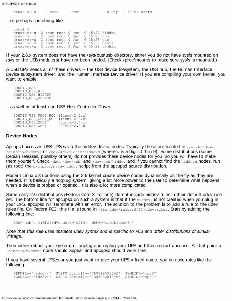
On Linux-2.6.x, make sure the sysfs filesystem is mounted on /sys and do:ls -l /sys/bus/usb/drivers/
...where you should get:total 0drwxr-xr-x 2 root root 0 May 1 18:55 hiddrwxr-xr-x 2 root root 0 May 1 18:55 hiddevdrwxr-xr-x 2 root root 0 May 1 18:55 hubdrwxr-xr-x 2 root root 0 May 1 18:55 usb
APCUPSD User Manual
http://www.apcupsd.com/manual/manual.html#installation-serial-line-upses[5/9/2014 1:39:41 PM]
drwxr-xr-x 2 root root 0 May 1 18:55 usbfs
...or perhaps something like:total 0drwxr-xr-x 2 root root 0 Jan 6 15:27 hiddevdrwxr-xr-x 2 root root 0 Jan 6 15:28 hubdrwxr-xr-x 2 root root 0 Jan 6 15:28 usbdrwxr-xr-x 2 root root 0 Jan 6 15:27 usbfsdrwxr-xr-x 2 root root 0 Jan 6 15:28 usbhid
If your 2.6.x system does not have the /sys/bus/usb directory, either you do not have sysfs mounted on/sys or the USB module(s) have not been loaded. (Check /proc/mounts to make sure sysfs is mounted.)
A USB UPS needs all of these drivers -- the USB device filesystem, the USB hub, the Human InterfaceDevice subsystem driver, and the Human Interface Device driver. If you are compiling your own kernel, youwant to enable
CONFIG_USBCONFIG_USB_HIDCONFIG_USB_HIDDEVCONFIG_USB_DEVICEFS
...as well as at least one USB Host Controller Driver...CONFIG_USB_UHCI_HCD (linux-2.6.x)CONFIG_USB_OHCI_HCD (linux-2.6.x)CONFIG_USB_UHCI (linux-2.4.x)CONFIG_USB_OHCI (linux-2.4.x)
Device Nodes
Apcupsd accesses USB UPSes via the hiddev device nodes. Typically these are located in /dev/hiddevN,/dev/usb/hiddevN or /dev/usb/hiddev/hiddevN (where N is a digit 0 thru 9). Some distributions (someDebian releases, possibly others) do not provides these device nodes for you, so you will have to makethem yourself. Check /dev, /dev/usb, and /dev/usb/hiddev and if you cannot find the hiddevN nodes, run(as root) the examples/make-hiddev script from the apcupsd source distribution.
Modern Linux distributions using the 2.6 kernel create device nodes dynamically on the fly as they areneeded. It is basically a hotplug system, giving a lot more power to the user to determine what happenswhen a device is probed or opened. It is also a lot more complicated.
Some early 2.6 distributions (Fedora Core 3, for one) do not include hiddev rules in their default udev ruleset. The bottom line for apcupsd on such a system is that if the hiddevN is not created when you plug inyour UPS, apcupsd will terminate with an error. The solution to the problem is to add a rule to the udevrules file. On Fedora FC3, this file is found in /etc/udev/rules.d/50-udev.rules. Start by adding thefollowing line:
BUS="usb", SYSFS{idVendor}="051d", NAME="usb/hiddev%n"
Note that this rule uses obsolete udev syntax and is specific to FC3 and other distributions of similarvintage.
Then either reboot your system, or unplug and replug your UPS and then restart apcupsd. At that point a/dev/usb/hiddevN node should appear and apcupsd should work fine.
If you have several UPSes or you just want to give your UPS a fixed name, you can use rules like thefollowing:
KERNEL=="hiddev*", SYSFS{serial}=="JB0319033692", SYMLINK="ups0"KERNEL=="hiddev*", SYSFS{serial}=="JB0320004845", SYMLINK="ups1"
APCUPSD User Manual
http://www.apcupsd.com/manual/manual.html#installation-serial-line-upses[5/9/2014 1:39:41 PM]
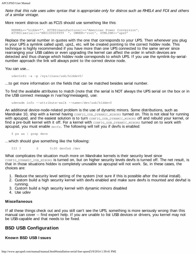
Note that this rule uses udev syntax that is appropriate only for distros such as RHEL4 and FC4 and othersof a similar vintage.
More recent distros such as FC15 should use something like this:KERNEL=="hiddev*", ATTRS{manufacturer}=="American Power Conversion", ATTRS{serial}=="BB0100009999 ", OWNER="root", SYMLINK+="ups0"
Replace the serial number in quotes with the one that corresponds to your UPS. Then whenever you plugin your UPS a symlink called ups0, ups1, etc. will be created pointing to the correct hiddev node. Thistechnique is highly recommended if you have more than one UPS connected to the same server sincerearranging your USB cables or even upgrading the kernel can affect the order in which devices aredetected and thus change which hiddev node corresponds to which UPS. If you use the symlink-by-serial-number approach the link will always point to the correct device node.
You can use...udevinfo -a -p /sys/class/usb/hiddev0/
...to get more information on the fields that can be matched besides serial number.
To find the available attributes to match (note that the serial is NOT always the UPS serial on the box or inthe USB connect message in /var/log/messages), use:
udevadm info --attribute-walk --name=/dev/usb/hiddev0
An additional device-node-related problem is the use of dynamic minors. Some distributions, such asMandrake 10, ship with a kernel having CONFIG_USB_DYNAMIC_MINORS turned on. This is not ideal for runningwith apcupsd, and the easiest solution is to turn CONFIG_USB_DYNAMIC_MINORS off and rebuild your kernel, orfind a pre-built kernel with it off. For a kernel with CONFIG_USB_DYNAMIC_MINORS turned on to work withapcupsd, you must enable devfs. The following will tell you if devfs is enabled:
$ ps ax | grep devs
...which should give something like the following:533 ? S 0:00 devfsd /dev
What complicates the situation much more on Mandrake kernels is their security level sinceCONFIG_DYNAMIC_USB_MINORS is turned on, but on higher security levels devfs is turned off. The net result, isthat in those situations hiddev is completely unusable so apcupsd will not work. So, in these cases, thechoices are:
1. Reduce the security level setting of the system (not sure if this is possible after the initial install).2. Custom build a high security kernel with devfs enabled and make sure devfs is mounted and devfsd is
running.3. Custom build a high security kernel with dynamic minors disabled4. Use udev
Miscellaneous
If all these things check out and you still can't see the UPS, something is more seriously wrong than thismanual can cover -- find expert help. If you are unable to list USB devices or drivers, you kernel may notbe USB-capable and that needs to be fixed.
BSD USB Configuration
Known BSD USB Issues
APCUPSD User Manual
http://www.apcupsd.com/manual/manual.html#installation-serial-line-upses[5/9/2014 1:39:41 PM]
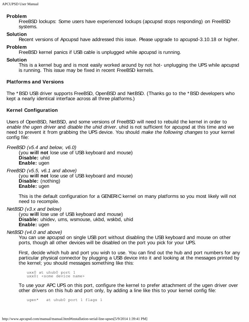
ProblemFreeBSD lockups: Some users have experienced lockups (apcupsd stops responding) on FreeBSDsystems.
SolutionRecent versions of Apcupsd have addressed this issue. Please upgrade to apcupsd-3.10.18 or higher.
ProblemFreeBSD kernel panics if USB cable is unplugged while apcupsd is running.
SolutionThis is a kernel bug and is most easily worked around by not hot- unplugging the UPS while apcupsdis running. This issue may be fixed in recent FreeBSD kernels.
Platforms and Versions
The *BSD USB driver supports FreeBSD, OpenBSD and NetBSD. (Thanks go to the *BSD developers whokept a nearly identical interface across all three platforms.)
Kernel Configuration
Users of OpenBSD, NetBSD, and some versions of FreeBSD will need to rebuild the kernel in order toenable the ugen driver and disable the uhid driver. uhid is not sufficient for apcupsd at this time and weneed to prevent it from grabbing the UPS device. You should make the following changes to your kernelconfig file:
FreeBSD (v5.4 and below, v6.0)(you will not lose use of USB keyboard and mouse)Disable: uhidEnable: ugen
FreeBSD (v5.5, v6.1 and above)(you will not lose use of USB keyboard and mouse)Disable: (nothing)Enable: ugen
This is the default configuration for a GENERIC kernel on many platforms so you most likely will notneed to recompile.
NetBSD (v3.x and below)(you will lose use of USB keyboard and mouse)Disable: uhidev, ums, wsmouse, ukbd, wskbd, uhidEnable: ugen
NetBSD (v4.0 and above)You can use apcupsd on single USB port without disabling the USB keyboard and mouse on otherports, though all other devices will be disabled on the port you pick for your UPS.
First, decide which hub and port you wish to use. You can find out the hub and port numbers for anyparticular physical connector by plugging a USB device into it and looking at the messages printed bythe kernel; you should messages something like this:
uxx0 at uhub0 port 1uxx0: <some device name>
To use your APC UPS on this port, configure the kernel to prefer attachment of the ugen driver overother drivers on this hub and port only, by adding a line like this to your kernel config file:
ugen* at uhub0 port 1 flags 1
APCUPSD User Manual
http://www.apcupsd.com/manual/manual.html#installation-serial-line-upses[5/9/2014 1:39:41 PM]
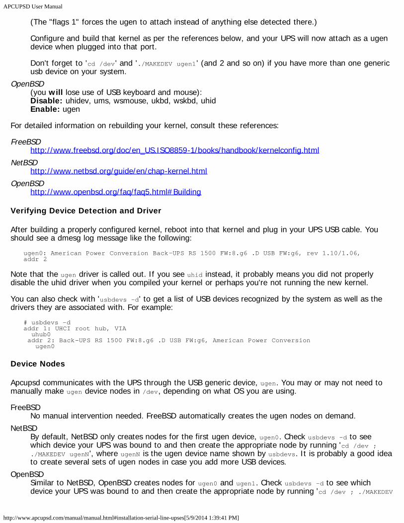
(The "flags 1" forces the ugen to attach instead of anything else detected there.)
Configure and build that kernel as per the references below, and your UPS will now attach as a ugendevice when plugged into that port.
Don't forget to 'cd /dev' and './MAKEDEV ugen1' (and 2 and so on) if you have more than one genericusb device on your system.
OpenBSD(you will lose use of USB keyboard and mouse):Disable: uhidev, ums, wsmouse, ukbd, wskbd, uhidEnable: ugen
For detailed information on rebuilding your kernel, consult these references:
FreeBSDhttp://www.freebsd.org/doc/en_US.ISO8859-1/books/handbook/kernelconfig.html
NetBSDhttp://www.netbsd.org/guide/en/chap-kernel.html
OpenBSDhttp://www.openbsd.org/faq/faq5.html#Building
Verifying Device Detection and Driver
After building a properly configured kernel, reboot into that kernel and plug in your UPS USB cable. Youshould see a dmesg log message like the following:
ugen0: American Power Conversion Back-UPS RS 1500 FW:8.g6 .D USB FW:g6, rev 1.10/1.06, addr 2
Note that the ugen driver is called out. If you see uhid instead, it probably means you did not properlydisable the uhid driver when you compiled your kernel or perhaps you're not running the new kernel.
You can also check with 'usbdevs -d' to get a list of USB devices recognized by the system as well as thedrivers they are associated with. For example:
# usbdevs -daddr 1: UHCI root hub, VIA uhub0 addr 2: Back-UPS RS 1500 FW:8.g6 .D USB FW:g6, American Power Conversion ugen0
Device Nodes
Apcupsd communicates with the UPS through the USB generic device, ugen. You may or may not need tomanually make ugen device nodes in /dev, depending on what OS you are using.
FreeBSDNo manual intervention needed. FreeBSD automatically creates the ugen nodes on demand.
NetBSDBy default, NetBSD only creates nodes for the first ugen device, ugen0. Check usbdevs -d to seewhich device your UPS was bound to and then create the appropriate node by running 'cd /dev ;./MAKEDEV ugenN ', where ugenN is the ugen device name shown by usbdevs. It is probably a good ideato create several sets of ugen nodes in case you add more USB devices.
OpenBSDSimilar to NetBSD, OpenBSD creates nodes for ugen0 and ugen1. Check usbdevs -d to see whichdevice your UPS was bound to and then create the appropriate node by running 'cd /dev ; ./MAKEDEV
APCUPSD User Manual
http://www.apcupsd.com/manual/manual.html#installation-serial-line-upses[5/9/2014 1:39:41 PM]
ugenN', where ugenN is the ugen device name shown by usbdevs. It is probably a good idea to createseveral sets of ugen nodes in case you add more USB devices.
Windows USB Configuration
Platforms and Versions
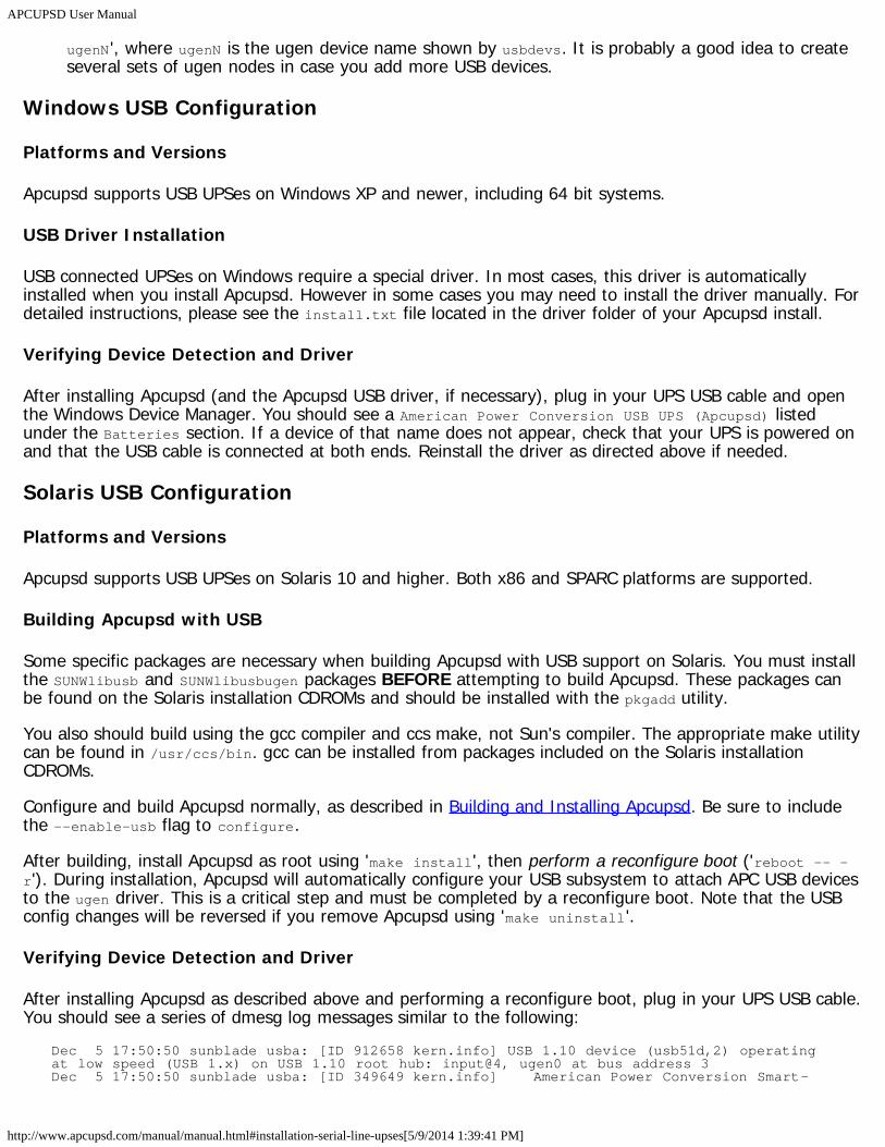
Apcupsd supports USB UPSes on Windows XP and newer, including 64 bit systems.
USB Driver Installation
USB connected UPSes on Windows require a special driver. In most cases, this driver is automaticallyinstalled when you install Apcupsd. However in some cases you may need to install the driver manually. Fordetailed instructions, please see the install.txt file located in the driver folder of your Apcupsd install.
Verifying Device Detection and Driver
After installing Apcupsd (and the Apcupsd USB driver, if necessary), plug in your UPS USB cable and openthe Windows Device Manager. You should see a American Power Conversion USB UPS (Apcupsd) listedunder the Batteries section. If a device of that name does not appear, check that your UPS is powered onand that the USB cable is connected at both ends. Reinstall the driver as directed above if needed.
Solaris USB Configuration
Platforms and Versions
Apcupsd supports USB UPSes on Solaris 10 and higher. Both x86 and SPARC platforms are supported.
Building Apcupsd with USB
Some specific packages are necessary when building Apcupsd with USB support on Solaris. You must installthe SUNWlibusb and SUNWlibusbugen packages BEFORE attempting to build Apcupsd. These packages canbe found on the Solaris installation CDROMs and should be installed with the pkgadd utility.
You also should build using the gcc compiler and ccs make, not Sun's compiler. The appropriate make utilitycan be found in /usr/ccs/bin. gcc can be installed from packages included on the Solaris installationCDROMs.
Configure and build Apcupsd normally, as described in Building and Installing Apcupsd. Be sure to includethe --enable-usb flag to configure.
After building, install Apcupsd as root using 'make install', then perform a reconfigure boot ('reboot -- -r'). During installation, Apcupsd will automatically configure your USB subsystem to attach APC USB devicesto the ugen driver. This is a critical step and must be completed by a reconfigure boot. Note that the USBconfig changes will be reversed if you remove Apcupsd using 'make uninstall'.
Verifying Device Detection and Driver
After installing Apcupsd as described above and performing a reconfigure boot, plug in your UPS USB cable.You should see a series of dmesg log messages similar to the following:
Dec 5 17:50:50 sunblade usba: [ID 912658 kern.info] USB 1.10 device (usb51d,2) operating at low speed (USB 1.x) on USB 1.10 root hub: input@4, ugen0 at bus address 3Dec 5 17:50:50 sunblade usba: [ID 349649 kern.info] American Power Conversion Smart-
APCUPSD User Manual
http://www.apcupsd.com/manual/manual.html#installation-serial-line-upses[5/9/2014 1:39:41 PM]
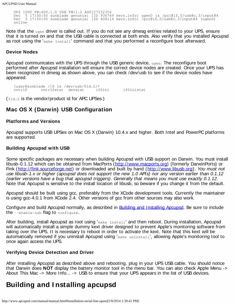
UPS 1000 FW:600.1.D USB FW:1.2 AS0127232356Dec 5 17:50:50 sunblade genunix: [ID 936769 kern.info] ugen0 is /pci@1f,0/usb@c,3/input@4Dec 5 17:50:50 sunblade genunix: [ID 408114 kern.info] /pci@1f,0/usb@c,3/input@4 (ugen0) online
Note that the ugen driver is called out. If you do not see any dmesg entries related to your UPS, ensurethat it is turned on and that the USB cable is connected at both ends. Also verify that you installed Apcupsdas root using the 'make install' command and that you performed a reconfigure boot afterward.
Device Nodes
Apcupsd communicates with the UPS through the USB generic device, ugen. The reconfigure bootperformed after Apcupsd installation will ensure the correct device nodes are created. Once your UPS hasbeen recognized in dmesg as shown above, you can check /dev/usb to see if the device nodes haveappeared:
[user@sunblade /]$ ls /dev/usb/51d.2/*cntrl0 cntrl0stat devstat if0in1 if0in1stat
(51d.2 is the vendor/product id for APC UPSes.)
Mac OS X (Darwin) USB Configuration
Platforms and Versions
Apcupsd supports USB UPSes on Mac OS X (Darwin) 10.4.x and higher. Both Intel and PowerPC platformsare supported.
Building Apcupsd with USB
Some specific packages are necessary when building Apcupsd with USB support on Darwin. You must installlibusb-0.1.12 which can be obtained from MacPorts (http://www.macports.org) (formerly DarwinPorts) orFink (http://fink.sourceforge.net) or downloaded and built by hand (http://www.libusb.org). You must notuse libusb-1.x or higher (apcupsd does not support the new 1.0 APIs) nor any version earlier than 0.1.12(earlier versions have a bug that apcupsd triggers). Generally that means you must use exactly 0.1.12.Note that Apcupsd is sensitive to the install location of libusb, so beware if you change it from the default.
Apcupsd should be built using gcc, preferably from the XCode development tools. Currently the maintaineris using gcc-4.0.1 from XCode 2.4. Other versions of gcc from other sources may also work.
Configure and build Apcupsd normally, as described in Building and Installing Apcupsd. Be sure to includethe --enable-usb flag to configure.
After building, install Apcupsd as root using 'make install' and then reboot. During installation, Apcupsdwill automatically install a simple dummy kext driver designed to prevent Apple's monitoring software fromtaking over the UPS. It is necessary to reboot in order to activate the kext. Note that this kext will beautomatically removed if you uninstall Apcupsd using 'make uninstall', allowing Apple's monitoring tool toonce again access the UPS.
Verifying Device Detection and Driver
After installing Apcupsd as described above and rebooting, plug in your UPS USB cable. You should noticethat Darwin does NOT display the battery monitor tool in the menu bar. You can also check Apple Menu ->About This Mac -> More Info... -> USB to ensure that your UPS appears in the list of USB devices.
Building and Installing apcupsd
APCUPSD User Manual
http://www.apcupsd.com/manual/manual.html#installation-serial-line-upses[5/9/2014 1:39:41 PM]
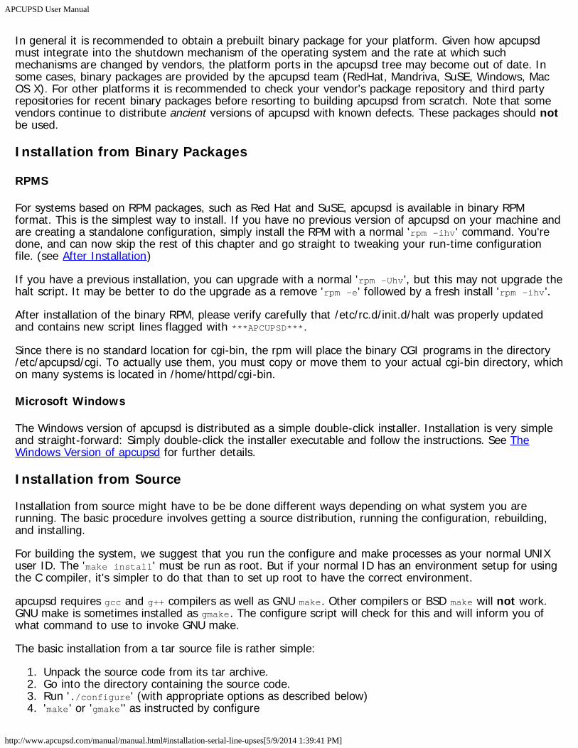
In general it is recommended to obtain a prebuilt binary package for your platform. Given how apcupsdmust integrate into the shutdown mechanism of the operating system and the rate at which suchmechanisms are changed by vendors, the platform ports in the apcupsd tree may become out of date. Insome cases, binary packages are provided by the apcupsd team (RedHat, Mandriva, SuSE, Windows, MacOS X). For other platforms it is recommended to check your vendor's package repository and third partyrepositories for recent binary packages before resorting to building apcupsd from scratch. Note that somevendors continue to distribute ancient versions of apcupsd with known defects. These packages should notbe used.
Installation from Binary Packages
RPMS
For systems based on RPM packages, such as Red Hat and SuSE, apcupsd is available in binary RPMformat. This is the simplest way to install. If you have no previous version of apcupsd on your machine andare creating a standalone configuration, simply install the RPM with a normal 'rpm -ihv' command. You'redone, and can now skip the rest of this chapter and go straight to tweaking your run-time configurationfile. (see After Installation)
If you have a previous installation, you can upgrade with a normal 'rpm -Uhv', but this may not upgrade thehalt script. It may be better to do the upgrade as a remove 'rpm -e' followed by a fresh install 'rpm -ihv'.
After installation of the binary RPM, please verify carefully that /etc/rc.d/init.d/halt was properly updatedand contains new script lines flagged with ***APCUPSD***.
Since there is no standard location for cgi-bin, the rpm will place the binary CGI programs in the directory/etc/apcupsd/cgi. To actually use them, you must copy or move them to your actual cgi-bin directory, whichon many systems is located in /home/httpd/cgi-bin.
Microsoft Windows
The Windows version of apcupsd is distributed as a simple double-click installer. Installation is very simpleand straight-forward: Simply double-click the installer executable and follow the instructions. See TheWindows Version of apcupsd for further details.
Installation from Source
Installation from source might have to be be done different ways depending on what system you arerunning. The basic procedure involves getting a source distribution, running the configuration, rebuilding,and installing.
For building the system, we suggest that you run the configure and make processes as your normal UNIXuser ID. The 'make install' must be run as root. But if your normal ID has an environment setup for usingthe C compiler, it's simpler to do that than to set up root to have the correct environment.
apcupsd requires gcc and g++ compilers as well as GNU make. Other compilers or BSD make will not work.GNU make is sometimes installed as gmake. The configure script will check for this and will inform you ofwhat command to use to invoke GNU make.
The basic installation from a tar source file is rather simple:
1. Unpack the source code from its tar archive.2. Go into the directory containing the source code.3. Run './configure' (with appropriate options as described below)4. 'make' or 'gmake'' as instructed by configure
APCUPSD User Manual
http://www.apcupsd.com/manual/manual.html#installation-serial-line-upses[5/9/2014 1:39:41 PM]
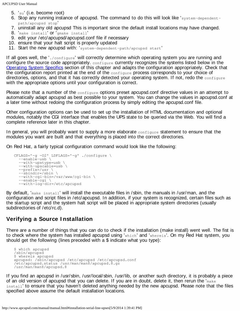
5. 'su' (i.e. become root)6. Stop any running instance of apcupsd. The command to do this will look like 'system-dependent-
path/apcupsd stop'7. uninstall any old apcupsd This is important since the default install locations may have changed.8. 'make install' or 'gmake install'9. edit your /etc/apcupsd/apcupsd.conf file if necessary
10. ensure that your halt script is properly updated11. Start the new apcupsd with: 'system-dependent-path/apcupsd start'
If all goes well, the './configure' will correctly determine which operating system you are running andconfigure the source code appropriately. configure currently recognizes the systems listed below in theOperating System Specifics section of this chapter and adapts the configuration appropriately. Check thatthe configuration report printed at the end of the configure process corresponds to your choice ofdirectories, options, and that it has correctly detected your operating system. If not, redo the configurewith the appropriate options until your configuration is correct.
Please note that a number of the configure options preset apcupsd.conf directive values in an attempt toautomatically adapt apcupsd as best possible to your system. You can change the values in apcupsd.conf ata later time without redoing the configuration process by simply editing the apcupsd.conf file.
Other configuration options can be used to set up the installation of HTML documentation and optionalmodules, notably the CGI interface that enables the UPS state to be queried via the Web. You will find acomplete reference later in this chapter.
In general, you will probably want to supply a more elaborate configure statement to ensure that themodules you want are built and that everything is placed into the correct directories.
On Red Hat, a fairly typical configuration command would look like the following:CFLAGS="-g -O2" LDFLAGS="-g" ./configure \ --enable-usb \ --with-upstype=usb \ --with-upscable=usb \ --prefix=/usr \ --sbindir=/sbin \ --with-cgi-bin=/var/www/cgi-bin \ --enable-cgi \ --with-log-dir=/etc/apcupsd
By default, 'make install' will install the executable files in /sbin, the manuals in /usr/man, and theconfiguration and script files in /etc/apcupsd. In addition, if your system is recognized, certain files such asthe startup script and the system halt script will be placed in appropriate system directories (usuallysubdirectories of /etc/rc.d).
Verifying a Source Installation
There are a number of things that you can do to check if the installation (make install) went well. The fist isto check where the system has installed apcupsd using 'which' and 'whereis'. On my Red Hat system, youshould get the following (lines preceded with a $ indicate what you type):
$ which apcupsd/sbin/apcupsd$ whereis apcupsdapcupsd: /sbin/apcupsd /etc/apcupsd /etc/apcupsd.conf/etc/apcupsd.status /usr/man/man8/apcupsd.8.gz/usr/man/man8/apcupsd.8
If you find an apcupsd in /usr/sbin, /usr/local/sbin, /usr/lib, or another such directory, it is probably a pieceof an old version of apcupsd that you can delete. If you are in doubt, delete it, then rerun the 'makeinstall' to ensure that you haven't deleted anything needed by the new apcupsd. Please note that the filesspecified above assume the default installation locations.
APCUPSD User Manual
http://www.apcupsd.com/manual/manual.html#installation-serial-line-upses[5/9/2014 1:39:41 PM]
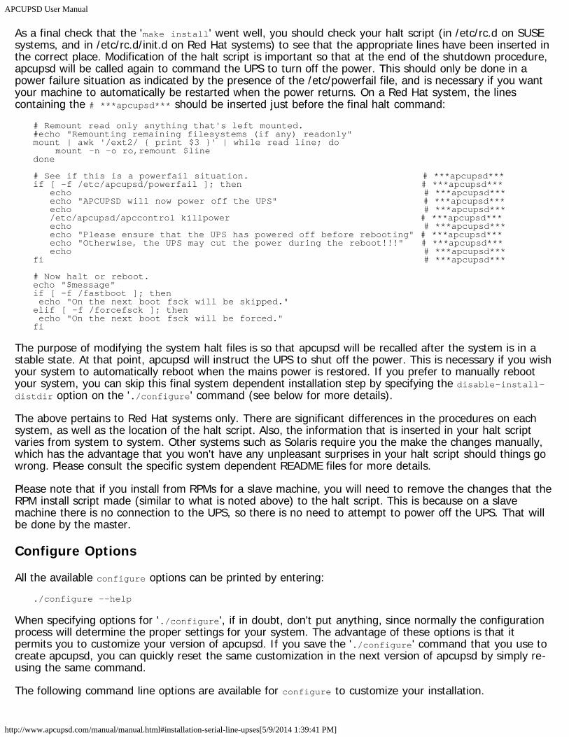
As a final check that the 'make install' went well, you should check your halt script (in /etc/rc.d on SUSEsystems, and in /etc/rc.d/init.d on Red Hat systems) to see that the appropriate lines have been inserted inthe correct place. Modification of the halt script is important so that at the end of the shutdown procedure,apcupsd will be called again to command the UPS to turn off the power. This should only be done in apower failure situation as indicated by the presence of the /etc/powerfail file, and is necessary if you wantyour machine to automatically be restarted when the power returns. On a Red Hat system, the linescontaining the # ***apcupsd*** should be inserted just before the final halt command:
# Remount read only anything that's left mounted.#echo "Remounting remaining filesystems (if any) readonly"mount | awk '/ext2/ { print $3 }' | while read line; do mount -n -o ro,remount $linedone
# See if this is a powerfail situation. # ***apcupsd***if [ -f /etc/apcupsd/powerfail ]; then # ***apcupsd*** echo # ***apcupsd*** echo "APCUPSD will now power off the UPS" # ***apcupsd*** echo # ***apcupsd*** /etc/apcupsd/apccontrol killpower # ***apcupsd*** echo # ***apcupsd*** echo "Please ensure that the UPS has powered off before rebooting" # ***apcupsd*** echo "Otherwise, the UPS may cut the power during the reboot!!!" # ***apcupsd*** echo # ***apcupsd***fi # ***apcupsd***
# Now halt or reboot.echo "$message"if [ -f /fastboot ]; then echo "On the next boot fsck will be skipped."elif [ -f /forcefsck ]; then echo "On the next boot fsck will be forced."fi
The purpose of modifying the system halt files is so that apcupsd will be recalled after the system is in astable state. At that point, apcupsd will instruct the UPS to shut off the power. This is necessary if you wishyour system to automatically reboot when the mains power is restored. If you prefer to manually rebootyour system, you can skip this final system dependent installation step by specifying the disable-install-distdir option on the './configure' command (see below for more details).
The above pertains to Red Hat systems only. There are significant differences in the procedures on eachsystem, as well as the location of the halt script. Also, the information that is inserted in your halt scriptvaries from system to system. Other systems such as Solaris require you the make the changes manually,which has the advantage that you won't have any unpleasant surprises in your halt script should things gowrong. Please consult the specific system dependent README files for more details.
Please note that if you install from RPMs for a slave machine, you will need to remove the changes that theRPM install script made (similar to what is noted above) to the halt script. This is because on a slavemachine there is no connection to the UPS, so there is no need to attempt to power off the UPS. That willbe done by the master.
Configure Options
All the available configure options can be printed by entering:./configure --help
When specifying options for './configure', if in doubt, don't put anything, since normally the configurationprocess will determine the proper settings for your system. The advantage of these options is that itpermits you to customize your version of apcupsd. If you save the './configure' command that you use tocreate apcupsd, you can quickly reset the same customization in the next version of apcupsd by simply re-using the same command.
The following command line options are available for configure to customize your installation.
APCUPSD User Manual
http://www.apcupsd.com/manual/manual.html#installation-serial-line-upses[5/9/2014 1:39:41 PM]
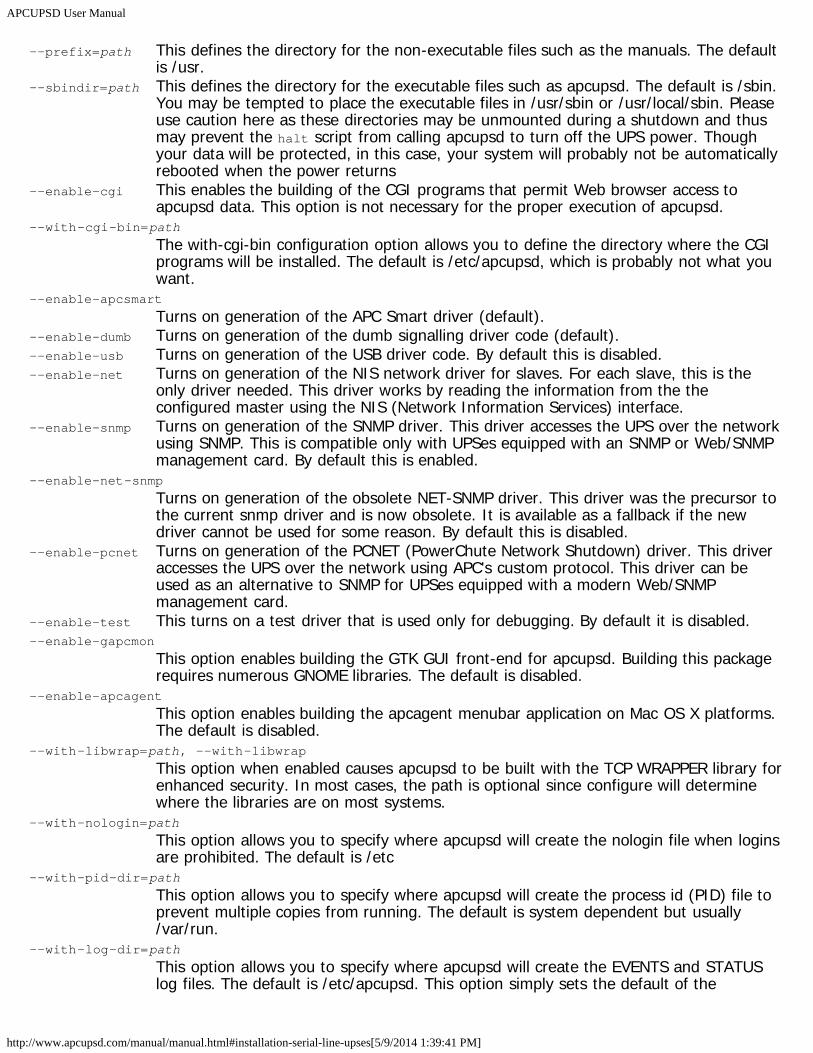
--prefix=path This defines the directory for the non-executable files such as the manuals. The defaultis /usr.
--sbindir=path This defines the directory for the executable files such as apcupsd. The default is /sbin.You may be tempted to place the executable files in /usr/sbin or /usr/local/sbin. Pleaseuse caution here as these directories may be unmounted during a shutdown and thusmay prevent the halt script from calling apcupsd to turn off the UPS power. Thoughyour data will be protected, in this case, your system will probably not be automaticallyrebooted when the power returns
--enable-cgi This enables the building of the CGI programs that permit Web browser access toapcupsd data. This option is not necessary for the proper execution of apcupsd.
--with-cgi-bin=path
The with-cgi-bin configuration option allows you to define the directory where the CGIprograms will be installed. The default is /etc/apcupsd, which is probably not what youwant.
--enable-apcsmart
Turns on generation of the APC Smart driver (default).--enable-dumb Turns on generation of the dumb signalling driver code (default).--enable-usb Turns on generation of the USB driver code. By default this is disabled.--enable-net Turns on generation of the NIS network driver for slaves. For each slave, this is the
only driver needed. This driver works by reading the information from the theconfigured master using the NIS (Network Information Services) interface.
--enable-snmp Turns on generation of the SNMP driver. This driver accesses the UPS over the networkusing SNMP. This is compatible only with UPSes equipped with an SNMP or Web/SNMPmanagement card. By default this is enabled.
--enable-net-snmp
Turns on generation of the obsolete NET-SNMP driver. This driver was the precursor tothe current snmp driver and is now obsolete. It is available as a fallback if the newdriver cannot be used for some reason. By default this is disabled.
--enable-pcnet Turns on generation of the PCNET (PowerChute Network Shutdown) driver. This driveraccesses the UPS over the network using APC's custom protocol. This driver can beused as an alternative to SNMP for UPSes equipped with a modern Web/SNMPmanagement card.
--enable-test This turns on a test driver that is used only for debugging. By default it is disabled.--enable-gapcmon
This option enables building the GTK GUI front-end for apcupsd. Building this packagerequires numerous GNOME libraries. The default is disabled.
--enable-apcagent
This option enables building the apcagent menubar application on Mac OS X platforms.The default is disabled.
--with-libwrap=path, --with-libwrap
This option when enabled causes apcupsd to be built with the TCP WRAPPER library forenhanced security. In most cases, the path is optional since configure will determinewhere the libraries are on most systems.
--with-nologin=path
This option allows you to specify where apcupsd will create the nologin file when loginsare prohibited. The default is /etc
--with-pid-dir=path
This option allows you to specify where apcupsd will create the process id (PID) file toprevent multiple copies from running. The default is system dependent but usually/var/run.
--with-log-dir=path
This option allows you to specify where apcupsd will create the EVENTS and STATUSlog files. The default is /etc/apcupsd. This option simply sets the default of the
APCUPSD User Manual
http://www.apcupsd.com/manual/manual.html#installation-serial-line-upses[5/9/2014 1:39:41 PM]
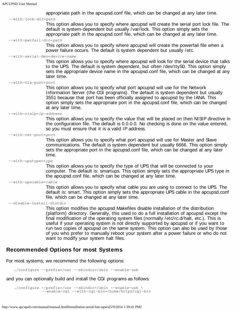
appropriate path in the apcupsd.conf file, which can be changed at any later time.--with-lock-dir=path
This option allows you to specify where apcupsd will create the serial port lock file. Thedefault is system-dependent but usually /var/lock. This option simply sets theappropriate path in the apcupsd.conf file, which can be changed at any later time.
--with-pwrfail-dir=path
This option allows you to specify where apcupsd will create the powerfail file when apower failure occurs. The default is system dependent but usually /etc.
--with-serial-dev=device-name
This option allows you to specify where apcupsd will look for the serial device that talksto the UPS. The default is system dependent, but often /dev/ttyS0. This option simplysets the appropriate device name in the apcupsd.conf file, which can be changed at anylater time.
--with-nis-port=port
This option allows you to specify what port apcupsd will use for the NetworkInformation Server (the CGI programs). The default is system dependent but usually3551 because that port has been officially assigned to apcupsd by the IANA. Thisoption simply sets the appropriate port in the apcupsd.conf file, which can be changedat any later time.
--with-nisip=ip-address
This option allows you to specify the value that will be placed on then NISIP directive inthe configuration file. The default is 0.0.0.0. No checking is done on the value entered,so you must ensure that it is a valid IP address.
--with-net-port=port
This option allows you to specify what port apcupsd will use for Master and Slavecommunications. The default is system dependent but usually 6666. This option simplysets the appropriate port in the apcupsd.conf file, which can be changed at any latertime.
--with-upstype=type
This option allows you to specify the type of UPS that will be connected to yourcomputer. The default is: smartups. This option simply sets the appropriate UPS type inthe apcupsd.conf file, which can be changed at any later time.
--with-upscable=cable
This option allows you to specify what cable you are using to connect to the UPS. Thedefault is: smart. This option simply sets the appropriate UPS cable in the apcupsd.conffile, which can be changed at any later time.
--disable-install-distdir
This option modifies the apcupsd Makefiles disable installation of the distribution(platform) directory. Generally, this used to do a full installation of apcupsd except thefinal modification of the operating system files (normally /etc/rc.d/halt, etc.). This isuseful if your operating system is not directly supported by apcupsd or if you want torun two copies of apcupsd on the same system. This option can also be used by thoseof you who prefer to manually reboot your system after a power failure or who do notwant to modify your system halt files.
Recommended Options for most Systems
For most systems, we recommend the following options:./configure --prefix=/usr --sbindir=/sbin --enable-usb
and you can optionally build and install the CGI programs as follows:./configure --prefix=/usr --sbindir=/sbin --enable-usb \ --enable-cgi --with-cgi-bin=/home/httpd/cgi-bin
APCUPSD User Manual
http://www.apcupsd.com/manual/manual.html#installation-serial-line-upses[5/9/2014 1:39:41 PM]
Compilers and Options
Some systems require unusual options for compilation or linking that the './configure' script does not knowabout. You can specify initial values for variables by setting them in the environment. Using a Bourne-compatible shell, you can do that on the command line like this:
CFLAGS="-O2 -Wall" LDFLAGS= ./configure
Or on systems that have the env program, you can do it like this:env CPPFLAGS=-I/usr/local/include LDFLAGS=-s ./configure
Or for example on the Sun Solaris system, you can use:setenv CFLAGS -O2setenv LDFLAGS -O./configure
You can get a listing of all available options by doing:./configure --help
or simply see the previous section of this manual.
Operating System Specifics
With the exception of Linux SUSE and Linux Red Hat systems used by the developers, we rely on users tohelp create installation scripts and instructions as well as to test that apcupsd runs correctly on theirsystem. As you can imagine, most of these people are system administrators rather than developers so theyare very busy and don't always have time to test the latest releases. With that in mind, we believe that youwill find that a lot of very valuable work has been already done to make your installation much easier (andprobably totally automatic).
Below, you will find a list of operating systems for which we have received installation files:
Debian (see Debian)FreeBSD (see FreeBSD)HPUX (see HPUX)NetBSD (see NetBSD)Mac OS X Darwin (see Mac OS X Darwin)OpenBSD (see OpenBSD)Red Hat (see Red Hat Systems)Slackware (see Slackware)SUSE (see SUSE)Solaris (see Sun Solaris)unknown (see Unknown System)Win32 (see Windows Systems)
Debian
This port is complete and is being used by several users. Since Debian build and install procedures aresomewhat particular, we have put the extra Debian information into the following two subdirectories:platforms/debian/examples and platforms/debian/packageinfo
You can also find the official Debian packages on the Debian site at:
https://packages.debian.org/stable/apcupsd
APCUPSD User Manual
http://www.apcupsd.com/manual/manual.html#installation-serial-line-upses[5/9/2014 1:39:41 PM]
https://packages.debian.org/testing/apcupsdhttps://packages.debian.org/unstable/apcupsd
FreeBSD
This port is complete and is being used by several users.
You will need to install and use GNU make (aka gmake) instead of the BSD make supplied with the system.
On the FreeBSD OS, there is no known way for a user program to get control when all the disks aresynced. This is needed for apcupsd to be able to issue the killpower command to the UPS so that the UPSshuts off the power. To accomplish the same thing on FreeBSD systems, make sure you have a SmartUPSand that your UPS shutdown grace period is set sufficiently long so that you system will power down(usually 2 minutes), the use the --kill-on-powerfail option on the apcupsd command line.
HPUX
Status of this port is unknown.
NetBSD
You will need to install and use GNU make (aka gmake) instead of the BSD make supplied with the system.
Mac OS X Darwin
On OS X (Darwin), apcupsd can be built with configure defaults. The USB driver can be enabled, as per thedirections on Mac OS X (Darwin) USB Configuration Apcupsd may be usable on OS X with a smart serialdevice, but certainly does work as a NIS client or using a USB interface.
The startup information will be installed in /Library/StartupItems/apcupsd which is part of darwin'sSystemStartup.
OpenBSD
You will need to install and use GNU make (aka gmake) instead of the BSD make supplied with the system.
Ensure that you read the distributions/openbsd/README file before running apcupsd. There are somecritical differences in how the OpenBSD implementation operates when the UPS batteries are exhausted.Failure to take this into account may result in the system not being fully halted when power is lost.
Red Hat Systems
Red Hat systems are fully supported, and by following the standard installation instructions given above,you should experience few or no problems.
Slackware
Slackware systems are fully supported, and by following the standard installation instructions given above,you should experience few or no problems.
SUSE
SUSE systems are fully supported, and by following the standard installation instructions given above, you
APCUPSD User Manual
http://www.apcupsd.com/manual/manual.html#installation-serial-line-upses[5/9/2014 1:39:41 PM]
should experience few or no problems.
Sun Solaris
Please read this before attempting to compile or install the beta software. It contains important informationthat will make your efforts easier.
Before running './configure', please be sure that you do not have /usr/ucb on your path. This may causethe configure to choose the wrong shutdown program. If configure detects that /usr/usb is on your path,it will print a warning message. Please follow the advice to avoid shutdown problems.
Your normal UNIX user ID must own the source tree directories, and you must have the normaldevelopment tools in your path. This includes make, the compiler, the M4 preprocessor, the linker, and aror ranlib. If the user you are logged in as can compile and link a C program from a source file, then youhave all the required tools available.
You will want to install the executables in a directory that remains mounted during the shutdown. Solariswill unmount almost everything except the root directories. Since the ability to power the UPS off requiresaccess to the executable programs, they need to be in a directory that will never be unmounted. And sincethey should also be in a directory that normal users cannot get into, /sbin is the default. However, pleasebe aware that if you want to follow Sun's filesystem conventions you would use the following:
./configure \ --prefix=/opt/apcupsd \ --sbindir=/etc/opt/apcupsd/sbin \ --sysconfdir=/etc/opt/apcupsd \ --with-cgi-bin=/opt/apcupsd/cgi-bin
The way to setup the /sbin directory as the executables directory is to pass configure the --sbindir=/sbinoption. No other arguments should be required, and your setup and platform should be detectedautomatically by configure.
Once you have run configure, you will need to do a 'gmake'. Once the make has completed with no errors,you must su to root to complete the install. After the su, you may not have a path to the make programanymore. In that case, you should do the 'gmake install' step as:
gmake install
Once the install completes, you must edit the /sbin/rc0 script as detailed below, then exit from the su'edshell.
In order to support unattended operation and shutdown during a power failure, it's important that the UPSremove power after the shutdown completes. This allows the unattended UPS to reboot the system whenpower returns by re-powering the system. Of course, you need autoboot enabled for your system to dothis, but all Solaris systems have this by default. If you have disabled this on your system, please re-enableit.
To get the UPS to remove power from the system at the correct time during shutdown, i.e., after the diskshave done their final sync, we need to modify a system script. This script is /sbin/rc0.
We do not have access to every version of Solaris, but we believe this file will be almost identical on everyversion. Please let us know if this is not true.
At the very end of the /sbin/rc0 script, you should find lines just like the following:# unmount file systems. /usr, /var and /var/adm are not unmounted by umountall# because they are mounted by rcS (for single user mode) rather than# mountall.# If this is changed, mountall, umountall and rcS should also change./sbin/umountall/sbin/umount /var/adm >/dev/null 2>\&1
APCUPSD User Manual
http://www.apcupsd.com/manual/manual.html#installation-serial-line-upses[5/9/2014 1:39:41 PM]
/sbin/umount /var >/dev/null 2>\&1/sbin/umount /usr >/dev/null 2>\&1
echo 'The system is down.'
We need to insert the following lines just before the last 'echo':#see if this is a powerfail situationif [ -f /etc/apcupsd/powerfail ]; then echo echo "APCUPSD will power off the UPS" echo /etc/apcupsd/apccontrol killpower echo echo "Please ensure that the UPS has powered off before rebooting" echo "Otherwise, the UPS may cut the power during the reboot!!!" echofi
We have included these lines in a file called rc0.solaris in the distributions/sun subdirectory of the sourcetree. You can cut and paste them into the /sbin/rc0 file at the correct place, or yank and put them using vior any other editor. Note that you must be root to edit this file.
You must be absolutely sure you have them in the right place. If your /sbin/rc0 file does not look like thelines shown above, do not modify the file. Instead, email a copy of the file to the maintainers, and we willattempt to figure out what you should do. If you mess up this file, the system will not shut down cleanly,and you could lose data. Don't take the chance.
You will then need to make the normal changes to the /etc/apcupsd/apcupsd.conf file. This file contains theconfiguration settings for the package. It is important that you set the values to match your UPS model andcable type, and the serial port that you have attached the UPS to. People have used both /dev/ttya and/dev/ttyb with no problems. You should be sure that logins are disabled on the port you are going to use,otherwise you will not be able to communicate with the UPS. If you are not sure that logins are disabled forthe port, run the 'admintool' program as root, and disable the port. The 'admintool' program is a GUIadministration program, and required that you are running CDE, OpenWindows, or another XWindowsprogram such as KDE.
Solaris probes the serial ports during boot, and during this process, it toggles some handshaking lines usedby dumb UPSes. As a result, particularly for simple signalling "dumb" UPSes it seems to kick it into a modethat makes the UPS think it's either in a calibration run, or some self-test mode. Since at this point we arereally not communicating with the UPS, it's pretty hard to tell what happened. But it's easy to prevent this,and you should. Disconnect the UPS, and boot the system. When you get to a login prompt, log in as root.Type the following command:
eeprom com1-noprobe=true
oreeprom com2-noprobe=true
depending on which com port your UPS is attached to. Then sync and shutdown the system normally,reattach the UPS, and reboot. This should solve the problem. However, we have some reports that recentversions of Solaris (7 & 8) appear to have removed this eeprom option and there seems to be no way tosuppress the serial port probing during boot.
At this point, you should have a complete installation. The daemon will load automatically at the next boot.Watch for any error messages during boot, and check the event logs in /etc/apcupsd. If everything looksOK, you can try testing the package by removing power from the UPS. NOTE! if you have a voltage-signalling UPS, please run the first power tests with your computer plugged into the wall rather than intothe UPS. This is because dumb serial-port UPSes have a tendency to power off if your configuration orcable are not correct.
APCUPSD User Manual
http://www.apcupsd.com/manual/manual.html#installation-serial-line-upses[5/9/2014 1:39:41 PM]
As a user, your input is very helpful in solving problems with the package, and providing suggestions andfuture directions for the development of the package. We are striving to provide a useful package thatworks across all platforms, and welcome your feedback.
Unknown System
During the './configure', if apcupsd does not find one of the systems for which it has specific installationprograms, it will set the Operating System to unknown and will use the incomplete installation scripts thatare in platforms/unknown. You will be on your own, or you can ask the developers list ([email protected]) for installation instructions. This directory also contains a hint file for LinuxFrom Scratch, which could be helpful for other systems as well.
Windows Systems
Appropriate scripts (actually Windows batch files) are included with the Apcupsd Win32 installer package.
After InstallationChecking Your Configuration File
Once you have installed apcupsd, either from a binary package or by building from source, your next stepshould be to inspect your /etc/apcupsd/apcupsd.conf file to make sure it is valid.
You can read the complete reference on configuration directives (Configuration Directive Reference), but ifyou are setting up a normal standalone configuration you should only need to check (and possibly fix) thefirst three items listed below.
Your UPSTYPE should be the UPS's protocol type: dumb, apcsmart, usb, net, pcnet, or snmp. Your UPSCABLEshould be the type of cable you are using.
DEVICE should be set to the path of the device node (usually in /dev) to use to communicate with the UPS.This is used primarily for serial port connections. If you have a USB device, it is better not to specify aDEVICE directive by leaving it black or commenting it out. Apcupsd will automatically search for your devicein the standard places. If you specify a DEVICE, it should be the name of the device that apcupsd is to useto communicate with the UPS.
If the first time you execute apcupsd, you get a message to the effect that the Apcupsd USB driver ismissing, it means that you most likely forgot to put --enable-usb on your './configure' command line.
The Configuration Examples chapter of this manual provides the essential characteristics of each main typeof configuration file. After those elements are correct, apcupsd should run, and then it is only a matter ofcustomization of your setup.
Arranging for Reboot on Power-Up
The final consideration for a automatic reboot after a full power down is to ensure that your computer willautomatically reboot when the power is restored.
This is not the normal behavior of most computers as shipped from the factory. Normally after the power iscut and restored, you must explicitly press a button for the power to actually be turned on. You can testyour computer by powering it down; shutting off the power (pull the plug); then plugging the cord back in.If your computer immediately starts up, good. There is nothing more to do.
If your computer does not start up, manually turn on the power (by pressing the power on button) and
APCUPSD User Manual
http://www.apcupsd.com/manual/manual.html#installation-serial-line-upses[5/9/2014 1:39:41 PM]
enter your computer's SETUP program (often by pressing DEL during the power up sequence; sometimes bypressing F10). You must then find and change the appropriate configuration parameter to permit instantpower on.
Normally, this is located under the BOOT menu item, and will be called something such as Restore onAC/Power Loss or Full-On. The exact words will vary according to the ROM BIOS provider. Generally youwill have three options: Last State, Power On, and Power Off. Although Last State should normally work,we recommend setting your computers to Power On. This means that whenever the power is applied theyare on. The only way to shut them off is to pull the plug or to have a special program that powers them off(/sbin/poweroff on Linux systems).
If after making all the changes suggested above, you cannot get your computer to automatically reboot,you might examine your halt script (/etc/rc.d/init.d/halt in the case of Red Hat Linux) and see if the finalline that performs the halt or reboot contains the -p option for powering down the computer. It should notwith the logic used by apcupsd, but if it does, the -p option could cause your computer to power off whilethe UPS is still suppling power (i.e. before the UPS kills the power). Depending on the setting of your BIOS,it may prevent your computer from restarting when the power returns. As already mentioned, this shouldnot apply, but in case of problems it is worth a try.
Making sure apcupsd Is Running
The simplest way to invoke apcupsd is from the command line by entering:/sbin/apcupsd
To do so, you must be root. However, normally, you will want apcupsd started automatically when yoursystem boots. On some systems with installation support (e.g. SUSE and Red Hat), the installationprocedure will create a script file that you will be automatically invoked when your system reboots. Onother systems, you will have to invoke apcupsd from your rc.local script.
On Red Hat systems, this script file that automatically invokes apcupsd on system start and stops is/etc/rc.d/init.d/apcupsd
To start apcupsd manually (as you will probably do immediately following the installation), enter thefollowing:
/etc/rc.d/init.d/apcupsd start
To understand how this file is automatically invoked at system startup and shutdown, see the man pagesfor chkconfig(8).
On SUSE systems, the script file that automatically invokes apcupsd on system start and stops is/etc/rc.d/apcupsd.
To start apcupsd manually (as you will probably do immediately following the installation), enter thefollowing:
/etc/rc.d/apcupsd start
Normally, when properly installed, apcupsd will be started and stopped automatically by your system.Unfortunately, the details are different for each system. Below, we give the commands for selectedsystems. Alternatively, there are simple stopapcupsd and startapcupsd scripts in the examples directory, oryou can modify one of the scripts in the distributions directory to meet your needs.
To stop apcupsd you can do the following:
On Red Hat systems:
APCUPSD User Manual
http://www.apcupsd.com/manual/manual.html#installation-serial-line-upses[5/9/2014 1:39:41 PM]
/etc/rc.d/init.d/apcupsd stop
On SUSE systems:/etc/rc.d/apcupsd stop
Please see the Testing Apcupsd chapter for more details on insuring that apcupsd is running properly.
Configuration ExamplesA Simple USB Configuration
If you have a USB UPS, the essential elements of your apcupsd.conf file should look like the following:## apcupsd.conf v1.1 ##UPSCABLE usbUPSTYPE usbDEVICELOCKFILE /var/lockUPSCLASS standaloneUPSMODE disable
Notice that we have not specified a device. In doing so, apcupsd will try all the well known USB ports. Westrongly recommend you use this (empty device address) form unless you have a good reason to dootherwise.
Please use the explicit specifications of a device only if you know exactly what you are doing. In general, itis much easier to let apcupsd find the device itself.
Please see USB Configuration for detailed help on setting up your system to work with a USB UPS.
A Simple Configuration for a Serial SmartUPS
If you have a Smart UPS using the serial cable supplied by APC, or you build a CUSTOM SMART cableoutlined in the cables chapter, a very simple configuration file would look like the following:
## apcupsd.conf v1.1 ##UPSCABLE smartUPSTYPE apcsmartDEVICE /dev/ttyS0LOCKFILE /var/lockUPSCLASS standaloneUPSMODE disable
Normally you would have many more configuration directives to completely customize your installation, butthis example shows you the minimum required.
A Simple Configuration for a Simple Signaling or Dumb
If you have a simple signaling or dumb UPS such as a BackUPS, you will need to know exactly what cableyou have and specify it on the UPSCABLE directive. Please see the list of UPSes versus cables in thebeginning of this document for more information. The cable number is normally stamped in the plastic atone end of the cable. If you specify the wrong cable, it is very likely that at the first power failure, yourcomputer will be immediately shutdown. This is an unfortunate consequence of the dumb signaling mode.To avoid this, first replace /etc/apcupsd/apccontrol with safe.apccontrol found in the examples directory,then test until everything works correctly. Once you have the correct cable, be sure to remember toreinstall the correct apccontrol file and test that your computer is correctly shutdown during a power failure.
## apcupsd.conf v1.1 ##UPSCABLE (number of cable you have)UPSTYPE dumb
APCUPSD User Manual
http://www.apcupsd.com/manual/manual.html#installation-serial-line-upses[5/9/2014 1:39:41 PM]
DEVICE /dev/ttyS0LOCKFILE /var/lockUPSCLASS standaloneUPSMODE disable
If your cable does not have low battery detection, as is the case with some older models, you will also needto define TIMEOUT nnn where you set nn to be the number of seconds on a power failure after which ashutdown is effected.
Normally you would have many more configuration directives to completely customize your installation, butthis example shows you the minimum required.
NIS Server/Client Configuration Using the Net Driver
NIS (Network Information Server) mode allows for communication between instances of apcupsd runningon different hosts. Only one of those hosts, the server, needs to talk to the UPS directly. The others,clients, obtain information about the state of the UPS by querying the server. NIS is not related to Sun'sNIS/YP services.
NIS clients and servers require that apcupsd be compiled with the Net Driver --enable-net. This is typicallyenabled by default.
The NIS server is connected to the UPS and should be configured exactly as a standalone configuration,but with NETSERVER on. In all other respects, the server should be configured in standalone mode. You mayalso set the NIS server specific options NISIP to restrict which IP address of the server which apcupsdlistens on. The default, 0.0.0.0, means to list on all of the server host's IP addresses; NISPORT (default3551) to set which TCP port the server listens on; and EVENTSFILE and EVENTSFILEMAX to provideinformation about the last few events to clients. You may also need to modify your firewall rules on theserver's host to allow traffic to the NISPORT.
For the NIS client computer, you will have a configuration that looks something like what follows. What isimportant is that you get the information from an UPSCABLE ether with UPSTYPE net over the network andyou must specify the address of a NIS server using DEVICE. The client apcupsd will then poll the NIS serverspecified in DEVICE every POLLTIME seconds (formerly NETTIME).
## apcupsd.conf v1.1 ##UPSCABLE etherUPSTYPE netLOCKFILE /var/lockDEVICE server-network-address:3551UPSCLASS standaloneUPSMODE disablePOLLTIME 10
The DEVICE is set to server-address:port, where server-address is the fully qualified domain name or IPaddress of the apcupsd NIS server, and port is the NISPORT that the server is listening on. The default is3551, but older versions of apcupsd used port 7000.
If you set POLLTIME too large, your client may not see the change in state of the NIS server before theserver has shutdown. Normally, you have at least 30 seconds of grace time between the time the NISserver decides to shutdown and the time it no longer responds. Your slave must poll during this interval.
Any client run using the Net driver will shutdown when its own timers expire or when the NIS server shutsdown, whichever occurs first. This means that if you want the slave to shutdown before the server, youneed only set BATTERYLEVEL, MINUTES or TIMEOUT on the client for a faster shutdown than the values definedon the NIS server. This can often be useful if the slave is less important than the master and you wish toreduce battery power consumption so that the master can remain up longer during a power outage.
NIS clients work principally by reading the STATFLAG record that is sent by the NIS server (present in theoutput of apcaccess). The low 16 bits are the standard APC status flag, and the upper 16 bits represent the
APCUPSD User Manual
http://www.apcupsd.com/manual/manual.html#installation-serial-line-upses[5/9/2014 1:39:41 PM]
internal state of apcupsd, so the slave can see when the power fails and know when to shutdown.
It would be possible to have a client also work as a server, but that would increase the delay of informationgetting from the UPS to the secondary client.
Differences between NIS Client/Server and the old (now removed) Master/Slave modes
The difference between the NIS mode and the removed master/slave mode is that the NIS server has noexplicit knowledge of the slaves. The NIS server makes its information available via the net (NIS), and theNIS slaves read it. When the NIS server is going to shutdown, it makes the information available to any NISslave that polls it, but the NIS server does not explicitly call each NIS slave as is the case in theMaster/Slave networking described several sections above.
Think of the difference as push (Master/Slave) vs. pull (NIS-based). In the case of M/S, the master makesall the shutdown decisions and notifies the slaves when they are to shut down or when some otherinteresting event happens. The slaves just do whatever the master says, whenever the master says to. Onthe other hand, with the NIS-based network config you basically "publish" the UPS status from one serverand then your clients view that status and make their own decisions.
PowerChute Network Shutdown Driver (PCNET)
As of 3.14, Apcupsd supports the PowerChute Network Shutdown protocol. This is an alternative to SNMPfor use with APC's AP9617 family of network smartslot modules. Note that the older AP9606 modules donot support PCNET.
To enable PCNET support, configure with the --enable-pcnet flag. This is typically enabled by default.
The required apcupsd.conf settings are straightforward:## apcupsd.conf v1.1 ##UPSCABLE etherUPSTYPE pcnetLOCKFILE /var/lockDEVICE ipaddr:user:passphraseUPSCLASS standaloneUPSMODE disable
The DEVICE setting specifies the IP address of the UPS as well as the username and authenticationpassphrase to use. Note that the username and passphrase are not the Web/SNMP login credentials. Theyare separate settings. The default username on a new card is "apc" and the default passphrase is "adminuser phrase". To change the passphrase, log in to the Web UI and go to the UPS tab, then to PowerChute-> Configuration. (This assumes firmware v3.3.1. Other versions may place the setting elsewhere.) Thepassword must be a minimum of 15 characters long. The web UI will silently ignore shorter passwords anddoes not give an error message. There is no apparent way to change the username.
Note that you may leave DEVICE blank and Apcupsd will accept information from any PCNET UPS on thenetwork, however it will be very insecure since an attacker could easily send packets crafted tocause your server to shut down. Using the ipaddr, user, and passphrase will prevent this behavior.
You may need to take steps to ensure networking stays active during your OS's shutdown sequence inorder for the PCNET driver to power off the UPS (the so-called "killpower" operation). On a Linux distro,you can use commands such as...
chkconfig --level 0 network onchkconfig --level 0 iptables on
...to make sure networking stays up.
MODBUS Driver
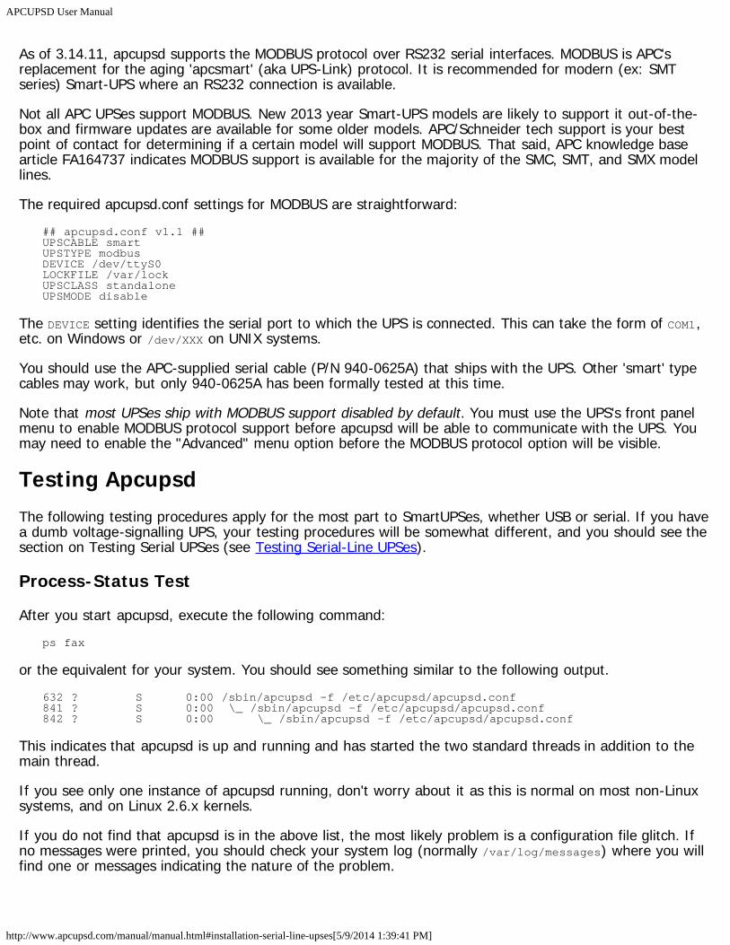
APCUPSD User Manual
http://www.apcupsd.com/manual/manual.html#installation-serial-line-upses[5/9/2014 1:39:41 PM]
As of 3.14.11, apcupsd supports the MODBUS protocol over RS232 serial interfaces. MODBUS is APC'sreplacement for the aging 'apcsmart' (aka UPS-Link) protocol. It is recommended for modern (ex: SMTseries) Smart-UPS where an RS232 connection is available.
Not all APC UPSes support MODBUS. New 2013 year Smart-UPS models are likely to support it out-of-the-box and firmware updates are available for some older models. APC/Schneider tech support is your bestpoint of contact for determining if a certain model will support MODBUS. That said, APC knowledge basearticle FA164737 indicates MODBUS support is available for the majority of the SMC, SMT, and SMX modellines.
The required apcupsd.conf settings for MODBUS are straightforward:## apcupsd.conf v1.1 ##UPSCABLE smartUPSTYPE modbusDEVICE /dev/ttyS0LOCKFILE /var/lockUPSCLASS standaloneUPSMODE disable
The DEVICE setting identifies the serial port to which the UPS is connected. This can take the form of COM1,etc. on Windows or /dev/XXX on UNIX systems.
You should use the APC-supplied serial cable (P/N 940-0625A) that ships with the UPS. Other 'smart' typecables may work, but only 940-0625A has been formally tested at this time.
Note that most UPSes ship with MODBUS support disabled by default. You must use the UPS's front panelmenu to enable MODBUS protocol support before apcupsd will be able to communicate with the UPS. Youmay need to enable the "Advanced" menu option before the MODBUS protocol option will be visible.
Testing ApcupsdThe following testing procedures apply for the most part to SmartUPSes, whether USB or serial. If you havea dumb voltage-signalling UPS, your testing procedures will be somewhat different, and you should see thesection on Testing Serial UPSes (see Testing Serial-Line UPSes).
Process-Status Test
After you start apcupsd, execute the following command:ps fax
or the equivalent for your system. You should see something similar to the following output.632 ? S 0:00 /sbin/apcupsd -f /etc/apcupsd/apcupsd.conf841 ? S 0:00 \_ /sbin/apcupsd -f /etc/apcupsd/apcupsd.conf842 ? S 0:00 \_ /sbin/apcupsd -f /etc/apcupsd/apcupsd.conf
This indicates that apcupsd is up and running and has started the two standard threads in addition to themain thread.
If you see only one instance of apcupsd running, don't worry about it as this is normal on most non-Linuxsystems, and on Linux 2.6.x kernels.
If you do not find that apcupsd is in the above list, the most likely problem is a configuration file glitch. Ifno messages were printed, you should check your system log (normally /var/log/messages) where you willfind one or messages indicating the nature of the problem.
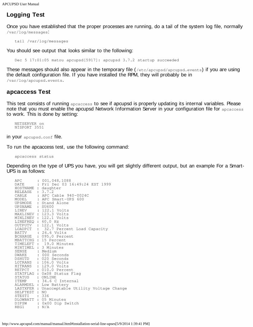
APCUPSD User Manual
http://www.apcupsd.com/manual/manual.html#installation-serial-line-upses[5/9/2014 1:39:41 PM]
Logging Test
Once you have established that the proper processes are running, do a tail of the system log file, normally/var/log/messages:
tail /var/log/messages
You should see output that looks similar to the following:Dec 5 17:01:05 matou apcupsd[5917]: apcupsd 3.7.2 startup succeeded
These messages should also appear in the temporary file (/etc/apcupsd/apcupsd.events) if you are usingthe default configuration file. If you have installed the RPM, they will probably be in/var/log/apcupsd.events.
apcaccess Test
This test consists of running apcaccess to see if apcupsd is properly updating its internal variables. Pleasenote that you must enable the apcupsd Network Information Server in your configuration file for apcaccessto work. This is done by setting:
NETSERVER onNISPORT 3551
in your apcupsd.conf file.
To run the apcaccess test, use the following command:apcaccess status
Depending on the type of UPS you have, you will get slightly different output, but an example For a Smart-UPS is as follows:
APC : 001,048,1088DATE : Fri Dec 03 16:49:24 EST 1999HOSTNAME : daughterRELEASE : 3.7.2CABLE : APC Cable 940-0024CMODEL : APC Smart-UPS 600UPSMODE : Stand AloneUPSNAME : SU600LINEV : 122.1 VoltsMAXLINEV : 123.3 VoltsMINLINEV : 122.1 VoltsLINEFREQ : 60.0 HzOUTPUTV : 122.1 VoltsLOADPCT : 32.7 Percent Load CapacityBATTV : 26.6 VoltsBCHARGE : 095.0 PercentMBATTCHG : 15 PercentTIMELEFT : 19.0 MinutesMINTIMEL : 3 MinutesSENSE : MediumDWAKE : 000 SecondsDSHUTD : 020 SecondsLOTRANS : 106.0 VoltsHITRANS : 129.0 VoltsRETPCT : 010.0 PercentSTATFLAG : 0x08 Status FlagSTATUS : ONLINEITEMP : 34.6 C InternalALARMDEL : Low BatteryLASTXFER : Unacceptable Utility Voltage ChangeSELFTEST : NOSTESTI : 336DLOWBATT : 05 MinutesDIPSW : 0x00 Dip SwitchREG1 : N/A
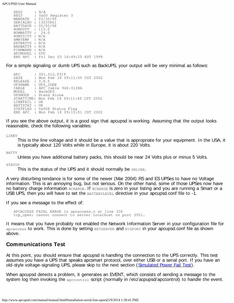
APCUPSD User Manual
http://www.apcupsd.com/manual/manual.html#installation-serial-line-upses[5/9/2014 1:39:41 PM]
REG2 : N/AREG3 : 0x00 Register 3MANDATE : 03/30/95SERIALNO : 13035861BATTDATE : 05/05/98NOMOUTV : 115.0NOMBATTV : 24.0HUMIDITY : N/AAMBTEMP : N/AEXTBATTS : N/ABADBATTS : N/AFIRMWARE : N/AAPCMODEL : 6TDEND APC : Fri Dec 03 16:49:25 EST 1999
For a simple signaling or dumb UPS such as BackUPS, your output will be very minimal as follows:APC : 001,012,0319DATE : Mon Feb 18 09:11:50 CST 2002RELEASE : 3.8.5UPSNAME : UPS_IDENCABLE : APC Cable 940-0128AMODEL : BackUPSUPSMODE : Stand AloneSTARTTIME: Mon Feb 18 09:11:45 CST 2002LINEFAIL : OKBATTSTAT : OKSTATFLAG : 0x008 Status FlagEND APC : Mon Feb 18 09:15:01 CST 2002
If you see the above output, it is a good sign that apcupsd is working. Assuming that the output looksreasonable, check the following variables:
LINEVThis is the line voltage and it should be a value that is appropriate for your equipment. In the USA, itis typically about 120 Volts while in Europe, it is about 220 Volts.
BATTVUnless you have additional battery packs, this should be near 24 Volts plus or minus 5 Volts.
STATUSThis is the status of the UPS and it should normally be ONLINE.
A very disturbing tendance is for some of the newer (Mar 2004) RS and ES UPSes to have no Voltageinformation. This is an annoying bug, but not serious. On the other hand, some of those UPSes now haveno battery charge information BCHARGE. If BCHARGE is zero in your listing and you are running a Smart or aUSB UPS, then you will have to set the BATTERYLEVEL directive in your apcupsd.conf file to -1.
If you see a message to the effect of:APCACCESS FATAL ERROR in apcaccess.c at line 336tcp_open: cannot connect to server localhost on port 3551.
It means that you have probably not enabled the Network Information Server in your configuration file forapcaccess to work. This is done by setting NETSERVER and NISPORT in your apcupsd.conf file as shownabove.
Communications Test
At this point, you should ensure that apcupsd is handling the connection to the UPS correctly. This testassumes you have a UPS that speaks apcsmart protocol, over either USB or a serial port. If you have anold-style voltage-signaling UPS, please skip to the next section (Simulated Power Fail Test).
When apcupsd detects a problem, it generates an EVENT, which consists of sending a message to thesystem log then invoking the apccontrol script (normally in /etc/acpupsd/apccontrol) to handle the event.
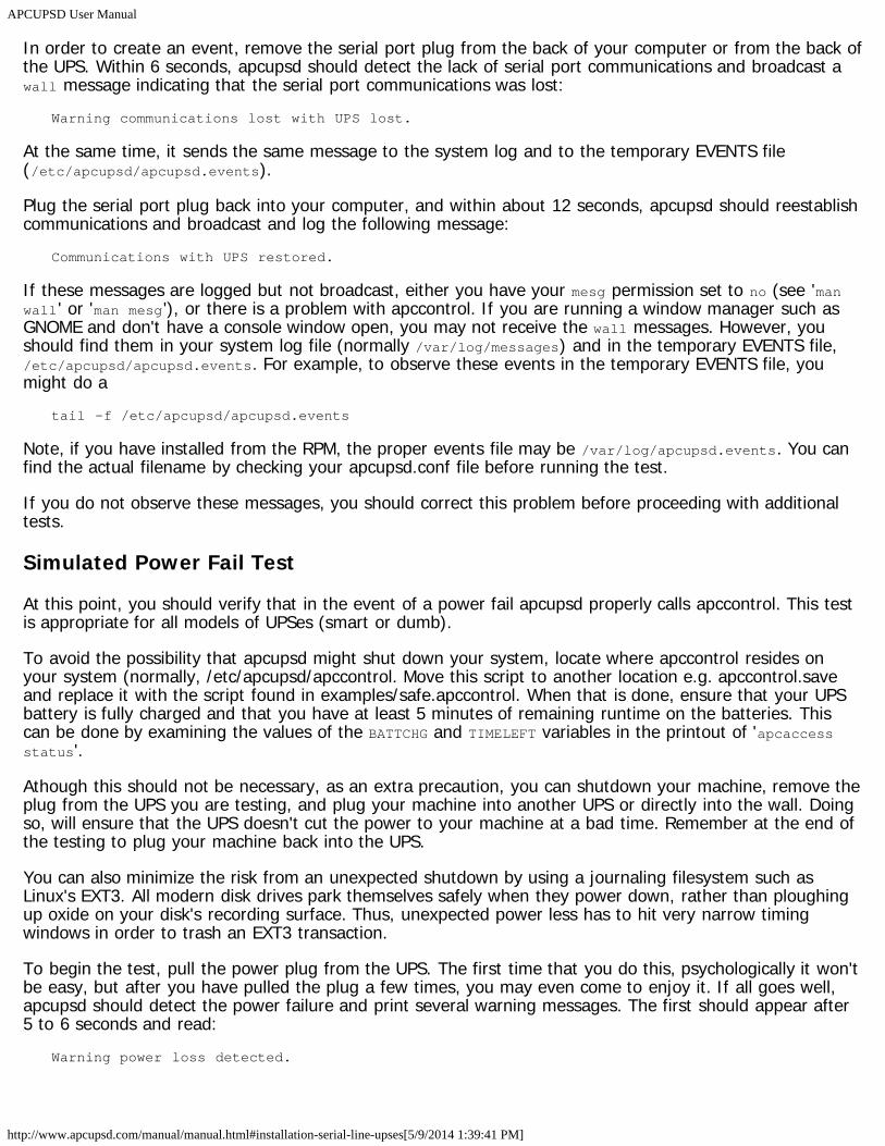
APCUPSD User Manual
http://www.apcupsd.com/manual/manual.html#installation-serial-line-upses[5/9/2014 1:39:41 PM]
In order to create an event, remove the serial port plug from the back of your computer or from the back ofthe UPS. Within 6 seconds, apcupsd should detect the lack of serial port communications and broadcast awall message indicating that the serial port communications was lost:
Warning communications lost with UPS lost.
At the same time, it sends the same message to the system log and to the temporary EVENTS file(/etc/apcupsd/apcupsd.events).
Plug the serial port plug back into your computer, and within about 12 seconds, apcupsd should reestablishcommunications and broadcast and log the following message:
Communications with UPS restored.
If these messages are logged but not broadcast, either you have your mesg permission set to no (see 'manwall' or 'man mesg'), or there is a problem with apccontrol. If you are running a window manager such asGNOME and don't have a console window open, you may not receive the wall messages. However, youshould find them in your system log file (normally /var/log/messages) and in the temporary EVENTS file,/etc/apcupsd/apcupsd.events. For example, to observe these events in the temporary EVENTS file, youmight do a
tail -f /etc/apcupsd/apcupsd.events
Note, if you have installed from the RPM, the proper events file may be /var/log/apcupsd.events. You canfind the actual filename by checking your apcupsd.conf file before running the test.
If you do not observe these messages, you should correct this problem before proceeding with additionaltests.
Simulated Power Fail Test
At this point, you should verify that in the event of a power fail apcupsd properly calls apccontrol. This testis appropriate for all models of UPSes (smart or dumb).
To avoid the possibility that apcupsd might shut down your system, locate where apccontrol resides onyour system (normally, /etc/apcupsd/apccontrol. Move this script to another location e.g. apccontrol.saveand replace it with the script found in examples/safe.apccontrol. When that is done, ensure that your UPSbattery is fully charged and that you have at least 5 minutes of remaining runtime on the batteries. Thiscan be done by examining the values of the BATTCHG and TIMELEFT variables in the printout of 'apcaccessstatus'.
Athough this should not be necessary, as an extra precaution, you can shutdown your machine, remove theplug from the UPS you are testing, and plug your machine into another UPS or directly into the wall. Doingso, will ensure that the UPS doesn't cut the power to your machine at a bad time. Remember at the end ofthe testing to plug your machine back into the UPS.
You can also minimize the risk from an unexpected shutdown by using a journaling filesystem such asLinux's EXT3. All modern disk drives park themselves safely when they power down, rather than ploughingup oxide on your disk's recording surface. Thus, unexpected power less has to hit very narrow timingwindows in order to trash an EXT3 transaction.
To begin the test, pull the power plug from the UPS. The first time that you do this, psychologically it won'tbe easy, but after you have pulled the plug a few times, you may even come to enjoy it. If all goes well,apcupsd should detect the power failure and print several warning messages. The first should appear after5 to 6 seconds and read:
Warning power loss detected.
APCUPSD User Manual
http://www.apcupsd.com/manual/manual.html#installation-serial-line-upses[5/9/2014 1:39:41 PM]
Then generally 6 seconds later, apcupsd is sure that it isn't a transient effect, so it sends:Power failure. Running on UPS batteries.
After a few more seconds (total around 15 seconds), plug the power cord back in and ensure that apcupsdis aware that the power has returned. It should print:
Power has returned...
If you do not observe the above messages, please correct the situation before proceeding. The most likelycause of problems are:
apcupsd doesn't recognize the power failure because the configuration directives are not correct. E.g.wrong cable.The file /etc/apcupsd/apccontrol doesn't exist or is not marked as executable.
System Shutdown Test
This is an intermediate test that you can do, for all UPS models before doing the Full Power Down Test.First modify the /etc/apcupsd/apccontrol file so that in the killpower case, the line that re-executesapcupsd with the --killpower option is commented out. The original line probably looks something like:
${APCUPSD} --killpower
when it is commented out, it looks like:#${APCUPSD} --killpower
Now when you pull the power plug, and either the timer expires or the batteries are exhausted (see thenext section for more details), the system should be fully shutdown.
After performing this test, please be sure to restore /etc/apcupsd/apccontrol to its previous state.
Full Power Down Test
To complete the testing, you should do a power fail shutdown of your system. This test is applicable to allUPS models. Please do a backup of your system or take other precautions before attempting this to avoidthe possibility of lost data due to a problem (I have been through this at least 10 times and never once hadproblems, but we all know that someday something will go wrong).
Before proceeding, please ensure that your halt script or the equivalent has been properly updated by theinstall process to contain the logic to call apcupsd --killpower or apccontrol killpower when it detects apower failure situation (the presence of a /etc/powerfail file). See the Building and Installing apcupsdsection of this manual, or the README files for additional details about the halt modifications necessary.
When you are ready to do the test, either simply pull the plug and wait for the batteries to becomeexhausted, or set the TIMEOUT configuration directive to something like 60 so that the system will shutdownbefore the batteries are exhausted. We recommend doing the full shutdown without using TIMEOUT tocorrectly simulate a real power failure, but the choice is yours (I did it once here, but now use TIMEOUT 30).
If all goes well, your system should be shutdown before the batteries are completely exhausted and theUPS should be powered off by apcupsd. Please be aware that if you do the full power down, you mustensure that your UPS is totally powered off. Otherwise, it may have been given the command to power off,but due to a long grace period it is still waiting. If you were to reboot your computer during the graceperiod, the UPS could then suddenly turn off the power (this happened to me). To avoid this problem,always wait for your UPS to power itself off, or power if off manually before restarting your computer. Onmy system, the UPS is configured as at the factory to have a 180 second grace period before shutting offthe power. During this type of testing, 180 seconds seems like an eternity, so please take care to either
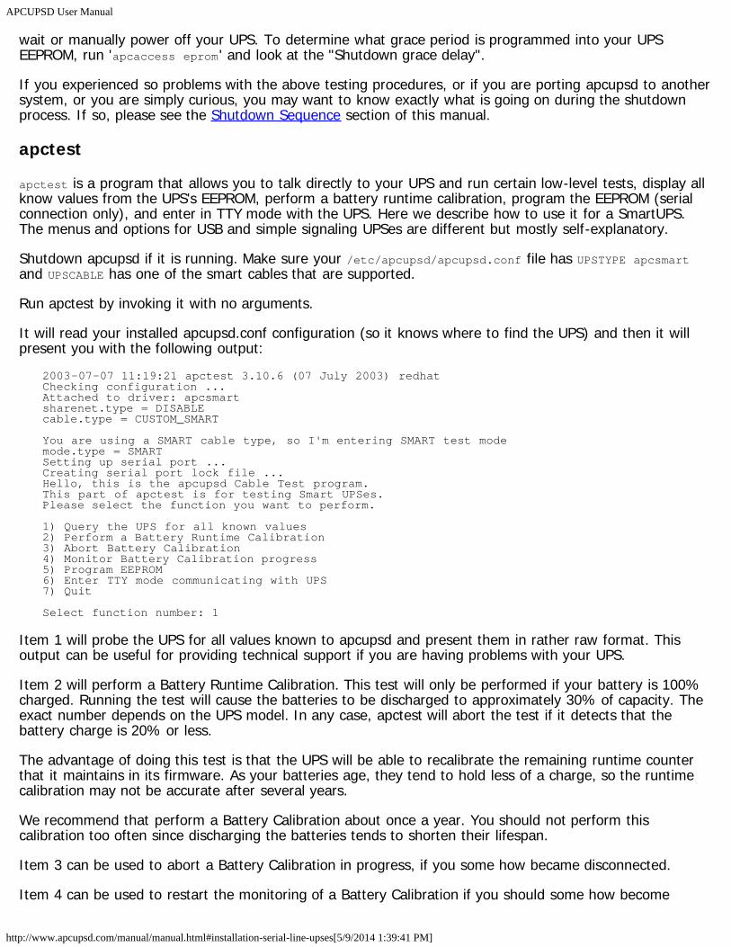
APCUPSD User Manual
http://www.apcupsd.com/manual/manual.html#installation-serial-line-upses[5/9/2014 1:39:41 PM]
wait or manually power off your UPS. To determine what grace period is programmed into your UPSEEPROM, run 'apcaccess eprom' and look at the "Shutdown grace delay".
If you experienced so problems with the above testing procedures, or if you are porting apcupsd to anothersystem, or you are simply curious, you may want to know exactly what is going on during the shutdownprocess. If so, please see the Shutdown Sequence section of this manual.
apctest
apctest is a program that allows you to talk directly to your UPS and run certain low-level tests, display allknow values from the UPS's EEPROM, perform a battery runtime calibration, program the EEPROM (serialconnection only), and enter in TTY mode with the UPS. Here we describe how to use it for a SmartUPS.The menus and options for USB and simple signaling UPSes are different but mostly self-explanatory.
Shutdown apcupsd if it is running. Make sure your /etc/apcupsd/apcupsd.conf file has UPSTYPE apcsmartand UPSCABLE has one of the smart cables that are supported.
Run apctest by invoking it with no arguments.
It will read your installed apcupsd.conf configuration (so it knows where to find the UPS) and then it willpresent you with the following output:
2003-07-07 11:19:21 apctest 3.10.6 (07 July 2003) redhatChecking configuration ...Attached to driver: apcsmartsharenet.type = DISABLEcable.type = CUSTOM_SMART
You are using a SMART cable type, so I'm entering SMART test modemode.type = SMARTSetting up serial port ...Creating serial port lock file ...Hello, this is the apcupsd Cable Test program.This part of apctest is for testing Smart UPSes.Please select the function you want to perform.
1) Query the UPS for all known values2) Perform a Battery Runtime Calibration3) Abort Battery Calibration4) Monitor Battery Calibration progress5) Program EEPROM6) Enter TTY mode communicating with UPS7) Quit
Select function number: 1
Item 1 will probe the UPS for all values known to apcupsd and present them in rather raw format. Thisoutput can be useful for providing technical support if you are having problems with your UPS.
Item 2 will perform a Battery Runtime Calibration. This test will only be performed if your battery is 100%charged. Running the test will cause the batteries to be discharged to approximately 30% of capacity. Theexact number depends on the UPS model. In any case, apctest will abort the test if it detects that thebattery charge is 20% or less.
The advantage of doing this test is that the UPS will be able to recalibrate the remaining runtime counterthat it maintains in its firmware. As your batteries age, they tend to hold less of a charge, so the runtimecalibration may not be accurate after several years.
We recommend that perform a Battery Calibration about once a year. You should not perform thiscalibration too often since discharging the batteries tends to shorten their lifespan.
Item 3 can be used to abort a Battery Calibration in progress, if you some how became disconnected.
Item 4 can be used to restart the monitoring of a Battery Calibration if you should some how become
APCUPSD User Manual
http://www.apcupsd.com/manual/manual.html#installation-serial-line-upses[5/9/2014 1:39:41 PM]
disconnected during the test.
Item 5 is used to program the EEPROM. Please see the Configuration Directives Used to Set the UPSEEPROM chapter of this manual for the details.
Item 6 will initiate a direct communication between your terminal and the UPS, at which point you canenter raw UPS commands. Please be aware that you should be careful what commands you enter becauseyou can cause your UPS to suddenly shutdown, or you can modify the EEPROM in a way to disable yourUPS. The details of the raw Smart mode UPS commands can be found in the APC Smart Protocol chapter ofthis manual.
Item 7 will terminate apctest.
Monitoring and Tuning your UPSAfter you have verified that your UPS is working correctly, you will probably want to query the state of itshealth occasionally. The tools apcupsd gives you to do this include one command-line utility (apcaccess)and a GUI you can use through a Web browser. You can also use apctest to tune some parameters of theUPS itself.
apcaccess
apcaccess is a program (normally found in /sbin/apcaccess) that permits you to print out the completestatus of your UPS.
apcaccess will use the Network Information Server to obtain the necessary information. You can specify asecond optional argument to apcaccess in the form of host:port where the :port is optional. The default islocalhost:3551. Please note that in versions prior to 3.10.6, the default NIS port was 7000, so if you aremixing versions, you will need to take a lot of care to ensure that all components are using the same port.
To enable the apcupsd Network Information Server, which is normally the default, you set:NETSERVER onNISPORT 3551
in your apcupsd.conf file.
The full form of the apcaccess command is:apcaccess status localhost:3551
where only apcaccess status should normally be needed. localhost may be replaced by any machine name,fully qualified domain name, or IP address, which means that apcaccess can access any UPS on thenetwork running the Network Information Server.
The status command line option of apcaccess will produce a full printout of all the STATUS variables usedby apcupsd. This can be very helpful for checking the condition of your UPS and to know whether or notapcupsd is properly connected to it.
Please note that if you invoke apcaccess within the first 30 seconds of launching apcupsd, you will likely getan error message such as:
APCACCESS FATAL ERROR in apcaccess.c at line 336tcp_open: cannot connect to server localhost on port 3551.
This is because apcupsd is still in the process of initializing the UPS. The solution is to wait at least 30seconds after starting apcupsd before launching apcaccess.
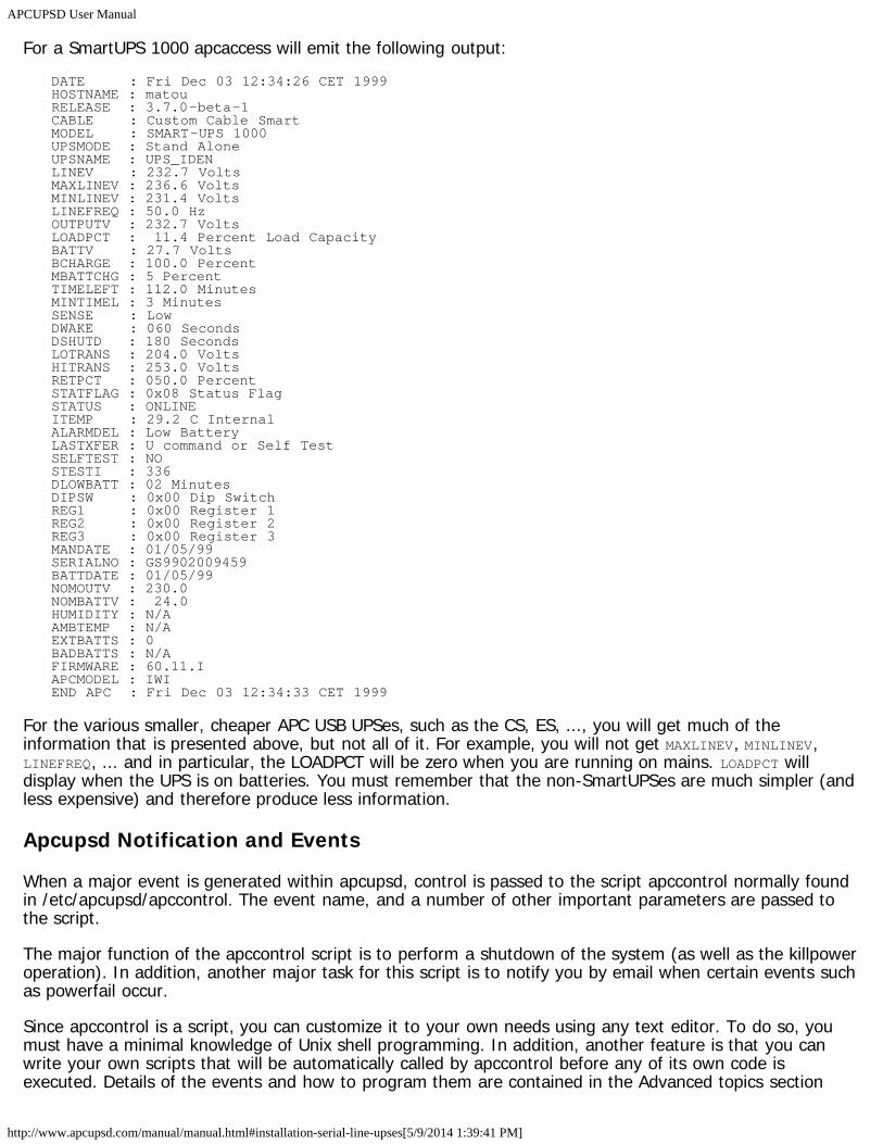
APCUPSD User Manual
http://www.apcupsd.com/manual/manual.html#installation-serial-line-upses[5/9/2014 1:39:41 PM]
For a SmartUPS 1000 apcaccess will emit the following output:DATE : Fri Dec 03 12:34:26 CET 1999HOSTNAME : matouRELEASE : 3.7.0-beta-1CABLE : Custom Cable SmartMODEL : SMART-UPS 1000UPSMODE : Stand AloneUPSNAME : UPS_IDENLINEV : 232.7 VoltsMAXLINEV : 236.6 VoltsMINLINEV : 231.4 VoltsLINEFREQ : 50.0 HzOUTPUTV : 232.7 VoltsLOADPCT : 11.4 Percent Load CapacityBATTV : 27.7 VoltsBCHARGE : 100.0 PercentMBATTCHG : 5 PercentTIMELEFT : 112.0 MinutesMINTIMEL : 3 MinutesSENSE : LowDWAKE : 060 SecondsDSHUTD : 180 SecondsLOTRANS : 204.0 VoltsHITRANS : 253.0 VoltsRETPCT : 050.0 PercentSTATFLAG : 0x08 Status FlagSTATUS : ONLINEITEMP : 29.2 C InternalALARMDEL : Low BatteryLASTXFER : U command or Self TestSELFTEST : NOSTESTI : 336DLOWBATT : 02 MinutesDIPSW : 0x00 Dip SwitchREG1 : 0x00 Register 1REG2 : 0x00 Register 2REG3 : 0x00 Register 3MANDATE : 01/05/99SERIALNO : GS9902009459BATTDATE : 01/05/99NOMOUTV : 230.0NOMBATTV : 24.0HUMIDITY : N/AAMBTEMP : N/AEXTBATTS : 0BADBATTS : N/AFIRMWARE : 60.11.IAPCMODEL : IWIEND APC : Fri Dec 03 12:34:33 CET 1999
For the various smaller, cheaper APC USB UPSes, such as the CS, ES, ..., you will get much of theinformation that is presented above, but not all of it. For example, you will not get MAXLINEV, MINLINEV,LINEFREQ, ... and in particular, the LOADPCT will be zero when you are running on mains. LOADPCT willdisplay when the UPS is on batteries. You must remember that the non-SmartUPSes are much simpler (andless expensive) and therefore produce less information.
Apcupsd Notification and Events
When a major event is generated within apcupsd, control is passed to the script apccontrol normally foundin /etc/apcupsd/apccontrol. The event name, and a number of other important parameters are passed tothe script.
The major function of the apccontrol script is to perform a shutdown of the system (as well as the killpoweroperation). In addition, another major task for this script is to notify you by email when certain events suchas powerfail occur.
Since apccontrol is a script, you can customize it to your own needs using any text editor. To do so, youmust have a minimal knowledge of Unix shell programming. In addition, another feature is that you canwrite your own scripts that will be automatically called by apccontrol before any of its own code isexecuted. Details of the events and how to program them are contained in the Advanced topics section
APCUPSD User Manual
http://www.apcupsd.com/manual/manual.html#installation-serial-line-upses[5/9/2014 1:39:41 PM]
entitled Customizing Event Handling.
apcupsd Network Monitoring (CGI) Programs
There are four CGI programs (multimon.cgi, upsstats.cgi, upsfstats.cgi, and upsimage.cgi). To have themproperly installed, you must run the './configure' command with --enable-cgi and you should specify aninstallation directory with --with-cgi-bin= or load them manually. The default directory for installation ofthe CGI programs is /etc/apcupsd, which is not really where you want them if you are going to use them.Normally, they should go in the cgi-bin of your Web server.
Once built and loaded, they will give you the status of your UPS or UPSes via a web browser.
Normally only multimon.cgi is directly invoked by the user. However, it is possible to directly invokeupsstats.cgi and upsfstats.cgi. upsimage.cgi should never be directly invoked as it is used byupsstats.cgi to produce the bar charts.
Setting up and Testing the CGI Programs
Before using multimon and the other CGI programs, first ensure that apcupsd is configured to run theNetwork Information Server. This is done by setting NETSERVER on in /etc/apcupsd/apcupsd.conf. Thisswitch is on by default.
Next you must edit the hosts file /etc/apcupsd/hosts.conf and at the end, add the name of the hosts youwant to monitor and a label string for them. For example:
MONITOR matou "Server"MONITOR polymatou "Backup server"MONITOR deuter "Disk server"
matou, polymatou, and deuter are the network names of the three machines currently running apcupsd.Please note that the network names may either be IP addresses or fully qualified domain names. Thenetwork name (or IP address) may optionally be followed by :port, where the port is the NIS port addressyou wish to use. This is useful if you are running multiple copies of apcupsd on the same system or if youare running in a mixed vendor environment where the NIS port assignments differ. An example could bethe following:
MONITOR matou "Server"MONITOR polymatou "Backup server"MONITOR deuter "Disk server"MONITOR polymatou:7001 "APC USB UPS"
where the USB copy of apcupsd has been configured to use port 7001 by modifying apcupsd.conf. Note, thedefault NIS port is 3551 on most platforms.
To test multimon.cgi, you can execute it as non-root directly from the source cgi build directory. To do so,enter at a shell prompt:
./multimon.cgi
If everything is set up correctly, it will print a bunch of HTML with the values of the machines that you haveput in the hosts.conf file. It should look something like the following (note, only a small portion of theoutput is reproduced here):
Content-type: text/html
<!DOCTYPE HTML PUBLIC "-//W3C//DTD HTML 4.0 Transitional//EN" "http://www.w3.org/TR/REC-html40/loose.dtd"><HTML><HEAD><TITLE>Multimon: UPS Status Page</TITLE></HEAD><BODY BGCOLOR="#FFFFFF"><TABLE BGCOLOR="#50A0A0" ALIGN=CENTER>
APCUPSD User Manual
http://www.apcupsd.com/manual/manual.html#installation-serial-line-upses[5/9/2014 1:39:41 PM]
<TR><TD><TABLE CELLPADDING=5><TR><TH COLSPAN=10 BGCOLOR="#60B0B0"><FONT SIZE="+2">APCUPSD UPS Network Monitor</FONT><BR>Sun Jan 16 12:07:27 CET 2000</TH></TR><TR BGCOLOR="#60B0B0"><TH COLSPAN=1>System</TH><TH COLSPAN=1>Model</TH><TH COLSPAN=1>Status</TH>...
If you do not get similar output, check the permissions of the /etc/apcupsd directory and of those of/etc/apcupsd/hosts.conf to ensure that your web server can access it. At many sites, the Apache server isnot running as root, so you must be careful to ensure that that /etc/apcupsd/hosts.conf and/etc/apcupsd/multimon.conf are world readable.
To invoke multimon in your Web browser, enter:
http://your-site/cgi-bin/multimon.cgi
You should get something similar to the screen shot shown below.
If you wish additional control over the colors, type faces, and sizes of the multimon output, you may simplyedit the apcupsd.css file to specify the styles you prefer.
Using the CGI Programs on Windows
The CGI programs compiled for Windows are included in the Windows package starting with apcupsd-3.14.7.
The CGI programs included with the Windows package are intended to be run on Windows. If your webserver is running on Linux or another operating system, you will need to obtain binary packages for thatplatform (or build them from source) instead. The windows build of the CGI programs has been tested withthe Apache web server for Win32. They should also work with MS Internet Information Server (IIS).
To use the programs, copy the contents of the cgi/ directory from your apcupsd installation directory to thecgi-bin/ directory of your web server. Consult your web server's documentation for how to enable CGIprograms to be executed. Sometimes special security settings are required.
Configure the hosts.conf file as described above. The programs expect to find the hosts.conf file and theapcupsd.css file in the directory \apcupsd\etc\apcupsd on the same drive letter as the web server's cgi-bindirectory. If you installed apcupsd into C:\apcupsd (the default) and your web server's cgi-bin/ directory isalso located on the C: drive, no further changes are necessary. If you installed apcupsd into a differentdirectory or your web server cgi-bin is on another drive, you will need to relocate hosts.conf andapcupsd.css from the apcupsd install location to \apcupsd\etc\apcupsd on the appropriate drive.
multimon.cgi
This program monitors multiple UPSes at the same time. A typical output of multimon.cgi as displayed inyour Web browser might look like the following:
The machines monitored as well as the values and their column headings are all configurable (see/etc/apcupsd/hosts.conf and /etc/apcupsd/multimon.conf)
upsstats.cgi
APCUPSD User Manual
http://www.apcupsd.com/manual/manual.html#installation-serial-line-upses[5/9/2014 1:39:41 PM]
By clicking on the system name in the multimon.cgi display, you will invoke upsstats.cgi for the specifiedsystem, which will produce a bar graph display of three of the monitored values. For example,
You can display different bar graphs by selecting different variables from the drop down menus at the topof each of the three bar graphs.
As with multimon, if you have your local host configured in the /etc/apcupsd/hosts.conf file, you canexecute it from a Unix shell from the source cgi directory as follows:
./upsstats.cgi
As with multimon, quite a few lines of html should then be displayed.
upsfstatus.cgi
If you would like to see all of the STATUS variables available over the network, click on the Data field of thedesired system, and your browser will display something like the following:
APC : 001,048,1109DATE : Thu Dec 02 17:27:21 CET 1999HOSTNAME : matou.sibbald.comRELEASE : 3.7.0-beta-1CABLE : Custom Cable SmartMODEL : SMART-UPS 1000UPSMODE : Stand AloneUPSNAME : UPS_IDENLINEV : 223.6 VoltsMAXLINEV : 224.9 VoltsMINLINEV : 222.3 VoltsLINEFREQ : 50.0 HzOUTPUTV : 223.6 VoltsLOADPCT : 6.2 Percent Load CapacityBATTV : 27.9 VoltsBCHARGE : 100.0 PercentMBATTCHG : 5 PercentTIMELEFT : 167.0 MinutesMINTIMEL : 3 MinutesSENSE : HighDWAKE : 060 SecondsDSHUTD : 020 SecondsLOTRANS : 196.0 VoltsHITRANS : 253.0 VoltsRETPCT : 050.0 PercentSTATFLAG : 0x08 Status FlagSTATUS : ONLINEITEMP : 35.1 C InternalALARMDEL : Low BatteryLASTXFER : U command or Self TestSELFTEST : NOSTESTI : 336DLOWBATT : 02 MinutesDIPSW : 0x00 Dip SwitchREG1 : 0x00 Register 1REG2 : 0x00 Register 2REG3 : 0x00 Register 3MANDATE : 01/11/99SERIALNO : GS9903001147BATTDATE : 01/11/99NOMOUTV : 230.0NOMBATTV : 24.0HUMIDITY : N/AAMBTEMP : N/AEXTBATTS : 0BADBATTS : N/AFIRMWARE : 60.11.IAPCMODEL : IWIEND APC : Thu Dec 02 17:27:25 CET 1999
You should get pretty much the same output mixed in with html if you execute upsfstats.cgi directly from a
APCUPSD User Manual
http://www.apcupsd.com/manual/manual.html#installation-serial-line-upses[5/9/2014 1:39:41 PM]
Unix shell in the cgi subdirectory as explained above for upsstats.cgi and multimon.cgi.
A Tip from Carl Erhorn for Sun Systems:
It is possible to run the CGI code to monitor your UPS using the answerbook HTTP server that runs onSolaris. As long as your server has the Answerbook2 web server installed and running, you can insert thecgi scripts into the cgi directory of the web server, and access the cgi using something like:
http://hostname:8888/cgi/multimon.cgi
CGI Credits
Many thanks go to Russell Kroll [email protected] who wrote the CGI programs to work with his UPSMonitoring system named Network UPS Tools (NUT). Thanks also to Jonathan [email protected] for initially adapting the upsstatus.cgi program to work with apcupsd.
We have enhanced the bar graph program and hope that our changes can be useful to the original authorin his project.
Security Issues:
apcupsd runs as root.If you have NETSERVER ON in your apcupsd.conf file (which is the default), be aware that anyone onthe network can read the status of your UPS. This may or may not pose a problem. If you don'tconsider this information privileged, as is the case for many, there is little risk. In addition, if you havea perimeter firewall or NATting router with typical settings only users on your local network access toyour UPS information. You may also restrict access using using firewall settings (see below) or TCPWrappers (see below).
Firewall Settings
If you are running apcupsd as an NIS server, you will need to ensure that the clients can reach it byopening up NISPORT (default: TCP 3551) on any firewall running on the server. You may wish to configureyour firewall(s) to only allow connections from your local network or specifically from the masters, slaves,and servers as needed.
TCP Wrappers
If your operating system does not support a host based firewall (a firewall running on the local machine)then you may try to get some of the functionality of such a firewall with TCP Wrappers. As of apcupsdversion 3.8.2, TCP Wrappers are implemented if you turn them on when configuring ./configure --with-libwrap. With this code enabled, you may control who may access your apcupsd via TCP connections (theNetwork Information Server). This control is done by modifying the file: /etc/hosts.allow. This code isimplemented but untested. If you use it, please send us some feedback.
Configuring Your EEPROM
If you have a SmartUPS, there are depending on the UPS at least 12 different values stored in the EEPROMthat determine how the UPS reacts to various conditions such as high line voltage, low line voltage, powerdown grace periods, etc.
In general, for the moment, we do not recommend that you change your EEPROM values unless absolutelynecessary. There have been several reported cases of problems setting the Low Transfer Voltage.Consequently, if at all possible, do not attempt to change this value.
APCUPSD User Manual
http://www.apcupsd.com/manual/manual.html#installation-serial-line-upses[5/9/2014 1:39:41 PM]
Using apctest to Configure Your EEPROM
To make the EEPROM changes with apctest you must first stop the apcupsd daemon. After apcupsd isstopped you may invoke apctest (as root).
We recommend that you change the EEPROM as little as is absolutely necessary since it is a somewhatdelicate process that has occasionally produced problems (i.e. improper EEPROM values are displayed afterthe update).
apctest will present a menu of options which are generally self-explanatory. Note that USB connections willshow a difference set of options than smart serial connections.
Maintaining Your UPS BatteriesBattery Technology
Sealed Lead Acid (SLA) batteries, otherwise known as Valve Regulated Lead Acid (VRLA) batteries, wereoriginally known as "dry batteries". When first introduced in the 1950s, they used a gel electrolyte. Theotherwise free acid was immobilised with a fine silica powder and formed a gel substance.
In the 1970s the technology moved to Absorbed Glass Mat (AGM) where the separators between the leadplates are made of highly porous micro-fine glass fibres which absorb and immobilise the acid and preventit from spilling. A crack or hole in the casing of a VRLA battery using AGM technology will not result in ameasurable electrolyte spill. Spill containment with VRLA batteries is therefore not meaningful orappropriate.
AGM has became the preferred VRLA technology for use in standby or float applications and is used inUPSes in the telecommunications, power, and many other mission critical industries where the power supplymust not be interrupted. APC UPSes use VRLA batteries. VRLA batteries are designed to recombinehydrogen and oxygen and emit only extremely small amounts of hydrogen under normal operatingconditions. Normal room ventilation is sufficient to remove any hydrogen, so special ventilation is notrequired.
Battery Life
Most brand name UPS batteries should last 3-5 years. Some APC Back-UPS models may have a shorterbattery life expectancy. Refer to the user's manual of your APC Back-UPS to determine the exact batterylife expectancy or contact APC Technical Support.
Below are some APC guidelines for ensuring optimum battery life expectancy:
1. Make sure that you keep your APC UPS in a cool, dry location with plenty of ventilation. Ideally, thetemperature where your UPS is kept should not exceed 75 Deg F (24 Deg C). Also, for ventilationpurposes, leave roughly one to two inches on each side for proper airflow.
2. The optimum operating temperature for a lead acid battery is 25 Deg C (77 Deg F). Elevatedtemperature reduces longevity. As a guideline, every 8 Deg C (15 Deg F) rise in temperature will cutthe battery life in half. A battery which would last for 6 years at 25 Deg C (77 Deg F), will only begood for 3 years if operated at 33 Deg C (95 Deg F). Keep in mind that the battery temperatureinside your UPS will always be warmer than the ambient temperature of the location where the UPS isinstalled.
3. Only perform runtime calibrations on your UPS one or two times a year, if necessary. Some of ourcustomers want to check their systems to verify that their runtime is sufficient. However, consistentlyperforming these calibrations can significantly decrease the life expectancy of your battery.
4. Do not store batteries for extended periods of time. New batteries can be stored for 6 to 12 months
APCUPSD User Manual
http://www.apcupsd.com/manual/manual.html#installation-serial-line-upses[5/9/2014 1:39:41 PM]
from date of purchase. After this period, the battery should be used or it will lose a great deal of itscharge. It is not advisable to store batteries that have already been in use.
5. Do not exceed 80 percent of a UPS unit's rated capacity due to the reduction in run time. When youincrease your load, your runtime decreases. In the event of a utility power failure, a UPS loaded to fullcapacity will drain and discharge it's battery quickly and will decrease the life expectancy.
The Smart-UPS detects line voltage distortions such as spikes, notches, dips, and swells, as well asdistortions caused by operation with inexpensive fuel-powered generators. By default, the UPS reacts todistortions by transferring to on-battery operation to protect the equipment that you are plugging into theUPS. Where power quality is poor, the UPS may frequently transfer to on-battery operation. Batterylongevity and service life of the UPS may be conserved by reducing the sensitivity of the UPS, as long asyour equipment can operate normally under the conditions detailed below. Any type of voltage disturbanceincludes; High/Low/No RMS Voltage, Total Harmonic Distortion(THD), Change in Voltage over Time(dv/dt),Frequency (Hz) out of tolerance.
High Sensitivity ModeIn the event of any type of voltage disturbance, the UPS will transfer to battery power and watch theAC line until it can transfer back to line. The transfer time in this mode depends on how far the linevoltage deviates from the sinewave reference.
Medium Sensitivity ModeIn the event of a RMS voltage-out-of-tolerance(High/Low/No) and RMS-rate-of-changedisturbances(dv/dt) in the line voltage, the UPS will transfer to battery power and watch the AC lineuntil it can transfer back to line. In this mode the transfer times are longer but still within acceptablelimits to insure the continuity of a computer's operation.
Low Sensitivity ModeIn the event of a RMS voltage-out-of-tolerance disturbances(High/Low/No) in the line voltage, theUPS will transfer to battery power and watch the AC line until it can transfer back to line. In thismode the transfer times are longer but still within acceptable limits to insure the continuity of acomputer's operation.
To change the sensitivity of the UPS, press the small, white "sensitivity" button on the rear of the UPS. Usea pointed object (such as a pen) to do so. The default setting is "high"; press the button once to set thesensitivity to "medium", and press it again to set it to "low"; pressing it a third time will set it back to"high". The sensitivity setting change will take effect immediately. The green LED next to the button is asensitivity setting indicator - brightly lit is "high" sensitivity, dimly lit is "medium", and off is "low"sensitivity.
Flashing Battery Charge Graph LEDs
The battery charge graph LEDs on the front panel of a Smart-UPS will flash in unison when the UPS isoperating online and the runtime remaining (calculated by the Smart-UPS microprocessor) is less than twominutes more than the low battery signal warning time (minimum of two minutes).
This would usually indicate that you need to either decrease the load or install new batteries. If thebatteries are new, then you need to perform a runtime calibration (see below).
At a pinch, you could also decrease the low battery warning time. There are four possible settings: 2, 5, 7,or 10 minutes.
Battery Replacement
If you own your UPS for long enough, you will inevitably need to replace the UPS battery or batterycartridge. An APC battery cartridge comprises two batteries physically stuck together with double-sided tapeand wired in series.
APCUPSD User Manual
http://www.apcupsd.com/manual/manual.html#installation-serial-line-upses[5/9/2014 1:39:41 PM]
After the decision to replace the batteries, you will face another decision almost immediately: whether topurchase genuine APC replacement batteries or not. There are pros and cons to purchasing genuinereplacement APC batteries.
APC Battery Pros
APC batteries are supported by APCAPC batteries come with all the necessary hardwareAPC batteries come as pre-made cartridgesAPC batteries will physically fit your UPS
APC Battery Cons
APC batteries cost up to 4 times the cost of third party batteries
There are also pros and cons to purchasing third party batteries.
Third Party Battery Pros
A third party battery may cost up to 1/4 the price of APC batteriesA third party battery may have a higher capacity for the same physical size
Third Party Battery Cons
You will need to recycle your battery hardware (cables, connectors etc)You will need to create your own battery cartridges (with double-sided tape)You will need to ensure the third party battery is the right physical sizeYou will need to ensure the third party battery is the right capacityUse of a third party battery will void APC's Equipment Protection PolicyUse of a third party battery may void UL, CSA, VDE, and other safety certifications (according to APC)
If you do decide to use third party replacement batteries, please do not choose the cheapest availablegeneric SLA batteries. These batteries will, almost without exception, not last as long as brand namebatteries and will need replacing within 12-18 months instead of 3-5 years. Even when using brand namereplacement batteries, make sure that you choose the UPS version (aka "standby") which may cost slightlymore, but which will last significantly longer in typical UPS usage (long periods of standby punctuated withinfrequent deep discharges).
The brands of battery found in genuine APC battery cartridges have included: Panasonic and B&B Battery(aka Best & Best Battery and BB Battery). Yuasa (aka Genesis) is also a recommended brand, albeit a bit onthe pricey side.
Note: When substituting a third party battery with a higher capacity than the original, make sure that itstill physically fits in the UPS casing. If the battery does not fit, do not be tempted to install it "externally".The UPS may not be able to charge it in a timely manner and/or it may damage the UPS charging circuitrywithout appropriate modifications which are generally beyond an end user's capability.
Battery Installation
Although you can do a hot swap of your batteries while the computer and any other connected equipmentis running, it may not be very satisfactory because the UPS will not always detect that the batteries havebeen swapped and apcupsd will continue to report "Low Battery".
There are several ways to correct this situation:
1. If you have a "smart" UPS model, you can force a self-test to make the UPS notice that the battery hasbeen replaced.
APCUPSD User Manual
http://www.apcupsd.com/manual/manual.html#installation-serial-line-upses[5/9/2014 1:39:41 PM]
2. If after a self-test, the UPS does not detect that the battery has been replaced, you can use apctest todo a soft battery runtime calibration. For details of doing this, refer to the "Soft" Runtime Calibration sectionbelow.
3. If after the soft battery runtime recalibration, the UPS does not detect that the battery has beenreplaced, you will need to do a manual battery runtime calibration. For details of doing this, refer to the"Manual" Runtime Calibration section below.
"Soft" Runtime Calibration
A runtime calibration causes the UPS to recalculate its available runtime capacity based on its current load.
Caution: a runtime calibration will deeply discharge the UPS batteries, which can leave a UPS temporarilyunable to support its equipment if a utility power failure occurs. Frequent calibrations reduce the life ofbatteries. APC recommends performing a runtime calibration only annually, semiannually, or whenever theload on the UPS is increased.
In order to perform a "soft" runtime calibration it is necessary to wait for the UPS to recharge its batteriesto 100% capacity. Once this has been done, you can then initiate a runtime calibration through apctest.
APC Documentation Notes:
1. In order for the calibration to be accurate, the output load has to be more than 40% (some APCdocumentation recommends at least 30%). Also, it is advisable not to increase or reduce the load when theUPS is calibrating its run time.
2. Under no circumstances should the UPS be turned off during a run time calibration procedure! Onceinitiated, the calibration must be allowed to run until completion.
3. The run time calibration procedure is not necessary nor advisable for a new UPS. Only old UPSes withbatteries that are not subject to discharge for long periods of time should be allowed to perform a run timecalibration.
4. Matrix-UPS and Smart-UPS recalculate the runtime-related parameters every time the UPS goes onbattery.
When doing a runtime calibration with "older" batteries, APC Technical Support recommend doing acomplete discharge and recharge first.
If you have "dumb" UPS (aka simple signalling) like a Back-UPS, then your only option is to do a manualruntime calibration.
"Manual" Runtime Calibration
Most of the information in this section is taken from APC's website. Any non-APC additions have beeninserted in square brackets.
For a "smart" or "smart signalling" Back-UPS Pro or Smart-UPS:
Perform a Runtime Calibration. This is a manual procedure and should not be confused with theruntime calibration performed through PowerChute plus [or apctest]. The batteries inside of theSmart-UPS are controlled by a microprocessor within the UPS. Sometimes it is necessary to resetthis microprocessor, especially after the installation of new batteries. Stop the PowerChute plus[or apcupsd] software from running and disconnect the serial cable. There must be at least a30% load attached to the UPS during this procedure, but the process will cause the UPS to shutoff and cut power to its outlets. Therefore, attach a non-critical load to the UPS and then force
APCUPSD User Manual
http://www.apcupsd.com/manual/manual.html#installation-serial-line-upses[5/9/2014 1:39:41 PM]
the UPS on battery by disconnecting it from utility power [suggest not disconnecting, but simplyturning off utility power thereby preserving earthing]. Allow the unit to run on battery until itturns off completely. Make sure a 30% load is present! Plug the UPS back into the wall outlet[switch utility power back on] and allow it to recharge (it will recharge more quickly turned offand with no load present). Once the unit has recharged, the "runtime remaining" calculationshould be more accurate. Remember that if the unit is an older model, then the runtime will notimprove significantly.
Background:
An APC Smart-UPS has a microprocessor which calculates runtime primarily based on the loadattached to the UPS and on its battery capacity. On the right side of the front display panelthere is a vertical graph of five LEDs. Each LED is an indication of battery charge in incrementsof twenty percent: 20, 40, 60, 80, 100% (bottom to top). For example, if the battery charge is99%, then only four of the five LEDs are illuminated.
To ensure that an operating system receives a graceful shutdown when using PowerChute plusor a SmartSlot accessory, an alert is generated by the Smart-UPS indicating that the UPS hasreached a low battery condition. The alert is audible (rapid beeping), visual (flashing battery LEDor LEDs), and readable through the graphical interface of PowerChute plus software (or a nativeUPS shutdown program within a particular operating system.) In order to calculate this "lowbattery condition," all Smart-UPS products have a preconfigured low battery signal warning timeof two minutes (this is the factory default setting). There are a total of four user-changeablesettings: 2, 5, 7, or 10 minutes. If the low battery signal warning time is set for 2 minutes, thenthe alerts will activate simultaneously two minutes prior to shutdown. Similarly, if the totalruntime for a particular UPS is 30 minutes with a low battery signal warning time set at 10minutes, then the UPS will run on battery for 20 minutes before the low battery alert begins.
Total runtime is primarily based on two factors, battery capacity and UPS load. UPS load andruntime on battery are inversely proportional: as load increases, battery runtime decreases andvice versa. When utility power is lost, the UPS begins discharging the battery in order to supportthe attached load. Once power returns, the Smart-UPS will automatically begin to recharge itsbattery.
For a Matrix UPS:
It is unnecessary to subject a battery bank to an excessively long calibration. Remove batterypacks or increase the load (space heaters are good dummy loads) to obtain a reasonable timelength for the calibration (under an hour if possible).
At the start of a calibration, the Matrix microprocessor saves the Estimated Run Time displayed.
The unit will then go to battery power until the capacity is 25%. After this run time has beencompleted, the original Estimated Run Time is compared with the actual run time. It will thenincrease or decrease this value to correspond to the new run time achieved. If, at any timeduring the discharge, one of the following rules is violated the calibration will be aborted orcorrupted:
1. Battery capacity must be 100% at start of calibration (all packs must indicated as float).2. Initial "Estimated Run Time" must not exceed 128 minutes (remove battery packs if
necessary).3. Load must be above 25%.4. Load must not fluctuate more than ± 5%.5. The UPS must be allowed to run down to 25% battery capacity. PowerChute [or apcupsd]
and Accessories must be removed since they can abort the calibration prematurely.
For a "dumb" or "simple signalling" UPS (eg a Back-UPS):
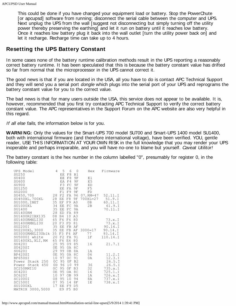
APCUPSD User Manual
http://www.apcupsd.com/manual/manual.html#installation-serial-line-upses[5/9/2014 1:39:41 PM]
This could be done if you have changed your equipment load or battery. Stop the PowerChute[or apcupsd] software from running; disconnect the serial cable between the computer and UPS.Next unplug the UPS from the wall [suggest not disconnecting but simply turning off the utilitypower thereby preserving the earthing] and let it run on battery until it reaches low battery.Once it reaches low battery plug it back into the wall outlet [turn the utility power back on] andlet it recharge. Recharge time can take up to 4 hours.
Resetting the UPS Battery Constant
In some cases none of the battery runtime calibration methods result in the UPS reporting a reasonablycorrect battery runtime. It has been speculated that this is because the battery constant value has driftedso far from normal that the microprocessor in the UPS cannot correct it.
The good news is that if you are located in the USA, all you have to do is contact APC Technical Supportand they will send you a serial port dongle which plugs into the serial port of your UPS and reprograms thebattery constant value for you to the correct value.
The bad news is that for many users outside the USA, this service does not appear to be available. It is,however, recommended that you first try contacting APC Technical Support to verify the correct batteryconstant value. The APC representatives in the Support Forum on the APC website are also very helpful inthis regard.
If all else fails, the information below is for you.
WARNING: Only the values for the Smart-UPS 700 model SU700 and Smart-UPS 1400 model SU1400,both with international firmware (and therefore international voltage), have been verified. YOU, gentlereader, USE THIS INFORMATION AT YOUR OWN RISK in the full knowledge that you may render your UPSinoperable and perhaps irreparable, and you will have no-one to blame but yourself. Caveat Utilitor!
The battery constant is the hex number in the column labelled "0", presumably for register 0, in thefollowing table:
UPS Model 4 5 6 0 Hex FirmwareSU250 EE F8 B1SU400 EE F8 9F E1SU600 EA F4 9F E5SU900 F3 FC 9F EDSU1250 EE FA 9F F5SU2000 F1 F9 9F FDSU450,700 28 F2 FA 96 07,RM=47 52.11.ISU450XL,700XL 28 EE F8 9F 700XL=27 51.9.ISU1000,INET 35 EF F9 A0 0B 60.11.ISU1000XL 34 EE FC 9A 2B 61.9.ISU1400 35 EE FC 9A 70.11.ISU1400RM 28 ED FA 89SU1400R2IBX135 08 B4 10 A3SU1400RMXLI3U 45 F6 F4 80 73.x.ISU1400RMXLI3U 20 F3 FD 81 73.x.ISU2200I 35 EE FB AF 90.14.ISU2200XL,3000 35 EE FB AF 3000=17 90.14.ISU3000RMXLI3Ublk 35 F3 F4 AF 77 93.14.ISU5000I white 20 F2 FA 91 1F 110.14.ISU1400XL,XLI,RM 45 F6 E4 80SU420I 25 95 09 85 16 21.7.ISU420SI 0E 95 0A 8CSU620I 29 99 0B 8A 1ABP420SI 0E 95 0A 8C 06 11.2.IBP650SI 10 97 0C 91 0A 12.3.IPower Stack 250 0C 95 0F B2 26.5.IPower Stack 450 0D 96 10 99 36 26.5.ISC250RMI1U 0C 95 0F B3 32 735.a.1SC420I 0E 95 OA 8C 16 725.1.ISC620I 10 97 OB 99 1A 726.x.ISC1000I 08 95 10 94 8A 737.x.ISC1500I 07 95 14 8F 1E 738.x.ISU1000XL 17 EE F9 D5MATRIX 3000,5000 E9 F5 B0
APCUPSD User Manual
http://www.apcupsd.com/manual/manual.html#installation-serial-line-upses[5/9/2014 1:39:41 PM]
SU700RMI2U 07 B1 0D 92 8A 152.4.ISU1000RMI2U 08 B5 0D C7 8E 157.3.ISU1400RMI2U 08 B4 10 A3 92 162.3.ISUA1000I 07 B5 13 BC 0A 652.12.ISUA1000XLI 0B BD 0F 7F 4A 681.13.ISUA750XLI 0A B9 0C 86 46 630.3.ISUA750I 04 B6 14 82 06 651.12.ISUA750RMI2U 07 B1 0D 82 86 619.12.ISUA1500I 09 B9 13 A1 0E 601/653.x.ISUA1500RMI2U 08 B4 10 A1 8E 617.3.ISUA2200I 08 B8 12 B3 26 654.12.ISUA2200RMI2U 09 BC 11 81 A6 665.4.ISUA2200XLI 0A B7 0F 7F 66 690.x.ISUA3000RMI2U 04 B9 0E 70 AA 666.4.ISUA3000RMXLI3U 0A B6 0E 89 xx xxx.x.xSUOL1000I 06 B6 1B A6SUOL2000XL 0D BD 14 75 52 416.5.ISURT1000XLI 0A BB 19 A8 4E 411.x.ISURT3000XLI 06 B6 0F CC 56 450.2.ISURT5000XLI 05 BA 15 86 5A 451.13.WSURT7500XLI 03 BB 20 97 63SURT10000XLI 06 B8 19 AB 476.12.WSUM1500RMXLI2U 03 B7 0D A5 62 716.3.ISUM3000RMXLI2U 03 B7 0D A5 6A 715.3.IBP500AVR 26 17.1.I
The instructions for resetting the battery constant are as follows:
1. Shutdown the apcupsd daemon;2. Run apctest;3. Choose option 6 to enter terminal mode;4. Enter Y (UPS should respond SM);5. Enter 1 (one, not el; wait 4 seconds);6. Enter 1 (one, not el; UPS should respond PROG);7. Enter 0 (zero, not oh; UPS should respond with current constant);8. Write down the existing value so that if something goes wrong, you can at least put it back to that
value;9. Enter + (plus) or - (minus) to increment/decrement the value;
10. Enter R to reprogram constant value (UPS should respond Bye);11. Enter Y (UPS should respond SM);12. Enter 0 (zero, not oh; UPS should respond with the new constant);13. Enter Esc to exit terminal mode;14. Choose option 7 to exit apctest.
Frequently-Asked QuestionsSee the bugs section of this document for a list of known bugs and solutions.
Question: Why all the craziness with custom serial cables?
Answer: It was nothing more nor less than a form of customer control. For a long time APC wanted tokeep other people from talking to its UPSes so it could lock out potential competition for itsPowerChute software. Scrambling the leads on its serial cables was a cheap way toaccomplish this -- in fact, they tended to be wired so that if you tried a straight-throughcable, opening a serial link to the UPS would be interpreted as a shutdown command!
(Hardware companies often think like this -- they lock up interfaces by instinct, cornering asmall market rather than growing a bigger one. It's fundamentally stupid and self-defeating,but it's the kind of stupid that tends to sound good at an executive meeting.)
Question: What UPS brands does apcupsd support?
Answer: Currently apcupsd supports only APC UPSes. However, some companies such as Hewlett
APCUPSD User Manual
http://www.apcupsd.com/manual/manual.html#installation-serial-line-upses[5/9/2014 1:39:41 PM]
Packard put their own brand name on APC manufactured UPSes. Thus even if you do nothave an APC branded UPS, it may work with apcupsd. You will need to know thecorresponding APC model number. apcupsd supports all the popular APC models. See theinstallation and configurations sections of this document for more details.
Question: Does apcupsd support Windows?
Answer: Yes.
Question: I don't have a cable, which one should I build?
Answer: First you must know if you have an apcsmart UPS or a voltage-signalling UPS. If you have aapcsmart UPS, we recommend building a Custom Smart cable. (see Smart-Custom Cable forSmartUPSes) If you have a voltage-signaling UPS, we recommend that you build a CustomSimple cable. (see Simple-Custom Voltage-Signalling Cable for "dumb" UPSes)
Question: How much CPU resources does apcupsd use?
Answer: Depending on your CPU speed, you may see more or less of the CPU consumed by apcupsd.On a 400MHz Unix system, the CPU usage should fall well below 0.1%. On slower systems,the percentage will increase proportionally to the decrease in the CPU speed. On a 400MhzWin98 machine, the CPU usage will be on the order of 0.5-1.0%. This is higher than for Unixsystems. However, compared to the 30% CPU usage by APC's PowerChute (the version onthe CDROM shipped with my UPS), apcupsd's 0.5-1.0% is very modest.
Question: What language is apcupsd written in?
Answer: It is written in C and C++.
Question: To test apcupsd, I unplugged the UPS to simulate a power outage. After the machine wentinto the shutdown process I plugged the UPS back into the commercial power source. Thiscaused the shutdown process to hang after the daemon tried to shut-off the ups. Have yourun into this problem, and if so do you have a remedy?
Answer: Normally, once the shutdown process has begun, we cannot stop it -- how do you stop ashutdown that has killed off half of the daemons running on your system? Most likely you willbe left with an unusable system. In addition, when apcupsd is re-executed in the halt scriptafter the disks are synced, it tries to shut off the UPS power, but the UPS will generallyrefuse to do so if the AC power is on. Since we cannot be 100% sure whether or not the UPSwill shut off the power, we don't attempt to reboot the system if we detect that the power isback as it might then get caught by a delayed power off (at least for Smart UPSes).
Question: After running apcupsd for a while, I get the following error: "Serial communications with UPSlost." What is the problem?
Answer: We use standard Unix serial port read() and write() calls so once a connection is made, wegenerally have few problems. However, there have been reports that APC's SNMPManagement Card can cause serial port problems. If you have such a card, we suggest thatyou remove it and see if the problem goes away. It is also possible that some other processsuch as a getty is reading the serial port.
Question: I get the following error:
Starting apcupsd power management.Mar 20 21:19:40 box apcupsd[297]: apcupsd FATAL ERROR in apcserial.c at line 83.Cannot open UPS tty /dev/cua01: No such file or directory.
APCUPSD User Manual
http://www.apcupsd.com/manual/manual.html#installation-serial-line-upses[5/9/2014 1:39:41 PM]
What is the problem?
Answer: The two most likely causes of your problem are: 1. You have the wrong serial port devicename in the apcupsd.conf file. 2. The device name is not defined on your system.Suggestions for proceeding:For the first item, check what your serial port device should benamed. You might be able to find the name with an:
ls /dev
Normally there will be hundreds or even thousands of names that print. If that doesn'tproduce anything useful, you can try step 2. Perhaps your device is not defined. To get moreinformation on your devices try 'man MAKEDEV' or 'find / -name MAKEDEV'. It is often located in/dev/MAKEDEV. Looking at the documentation may tell you what the correct name is, or atleast allow you to create the device.
Question: How do I ensure that the slaves shutdown before the master?
Answer: Slaves make their shutdown decision independently from the master. Therefore you can usethe TIMEOUT, MINUTES, and BATTERYLEVEL settings in the slaves' apcupsd.conf to configurethem to shut down before the master.
Question: How do I ensure that my database server is correctly shutdown?
Answer: You simply add whatever commands are necessary in the appropriate case statements in/etc/apcupsd/apccontrol, which is a standard script file that is called to actually do theshutdown. Alternatively, you can add your own script file that will be called before doing thecommands in apccontrol. Your script file must have the same name as the appropriate casestatement in apccontrol; it must be executable; and it must be in the same directory asapccontrol.
Customizing Event HandlingWhen apcupsd detects anomalies from your UPS device, it will make some decisions that usually result inone or more calls to the script located in /etc/apcupsd/apccontrol. The apccontrol file is a shell script thatacts on the first argument that apcupsd passes to it. These actions are set up by default to sane behaviorfor all situations apcupsd is likely to detect from the UPS. However, you can change the apccontrol behaviorfor every single action.
To customize, so create a file with the same name as the action, which is passed as a command lineargument. Put your script in the /etc/apcupsd directory.
These events are sent to the system log, optionally sent to the temporary events file(/etc/apcupsd/apcupsd.events), and they also generate a call to /etc/apcupsd/apccontrol which in turn willcall any scripts you have placed in the /etc/apcupsd directory.
Normally, /etc/apcupsd/apccontrol is called only by apcupsd. Consequently, you should not invoke itdirectly. However, it is important to understand how it functions, and in some cases, you may want tochange the messages that it prints using wall. We recommend that you do so by writing your own script tobe invoked by apccontrol rather than by modifying apccontrol directly. This makes it easier for you toupgrade to the next version of apcupsd
In other case, you may want to write your own shell scripts that will be invoked by apccontrol. Forexample, when a power fail occurs, you may want to send an email message to root.
To write your own routine for the powerout action, you create shell script named powerout and put it in thelib directory (normally /etc/apcupsd). When the powerout action is invoked by apcupsd, apccontrol will first
APCUPSD User Manual
http://www.apcupsd.com/manual/manual.html#installation-serial-line-upses[5/9/2014 1:39:41 PM]
give control to your script. If you want apccontrol to continue with the default action, simply exit your scriptwith an exit status of zero. If you do not want apccontrol to continue with the default action, your scriptshould exit with the special exit code of 99. However, in this case, please be aware that you must ensureproper shutdown of your machine if necessary.
Some sample scripts (onbattery and mainsback) that email power failure messages can be found in/etc/apcupsd after an install or in the platforms/etc directory of the source code.
apccontrol Command Line Options
When apcupsd detects an event, it calls the apccontrol script with four arguments as:
apccontrol event ups-name connected powered
where:
eventis the event that occurred and it may be any one of the values described in the next section.
ups-nameis the name of the UPS as specified in the configuration file (not the name in the EEPROM).
connectedis 1 if apcupsd is connected to the UPS via a serial port (or a USB port). In most configurations, thiswill be the case. In the case of a Slave machine where apcupsd is not directly connected to the UPS,this value will be 0.
poweredis 1 if the computer on which apcupsd is running is powered by the UPS and 0 if not. At the moment,this value is unimplemented and always 0.
The following event names are supported:
annoymeWhen a shutdown is scheduled, and the time specified on the ANNOYME directive in the apcupsd.conffile expires, this event is generated.
Default: wall a messagechangeme
When apcupsd detects that the mains are on, but the battery is not functioning correctly, this event isgenerated. It is repeated every x hours.
Default: wall a messagecommfailure
This event is generated each time the communications line with the computer is severed. This event isnot detected on dumb signaling UPSes.
Default: wall a messagecommok
After a commfailure event is issued, when the communications to the computer is re-established, thisevent will be generated.
Default: wall a messagedoreboot
This event is depreciated and should not be used.
Default: Shuts down the system using shutdown -h or similar
APCUPSD User Manual
http://www.apcupsd.com/manual/manual.html#installation-serial-line-upses[5/9/2014 1:39:41 PM]
doshutdownWhen the UPS is running on batteries and one of the limits expires (time, run, load), this event isgenerated to cause the machine to shutdown.
Default: Shuts down the system using shutdown -h or similaremergency
Called for an emergency system shutdown. (What triggers such a shutdown is unclear...) Aftercompleting this event, apcupsd will immediately initiate a doshutdown event.
Default: wall a messagefailing
This event is generated when the UPS is running on batteries and the battery power is exhausted.The event following this one will be a shutdown.
Default: wall a messageloadlimit
This event is generated when the battery charge is below the low limit specified in the apcupsd.conffile. After completing this event, apcupsd will immediately initiate a doshutdown event.
Default: wall a messagepowerout
This event is generated immediately when apcupsd detects that the UPS has switched to batteries. Itmay be due to a short powerfailure, an automatic selftest of the UPS, or a longer powerfailure.
Default: wall a messageonbattery
This event is generated 5 or 6 seconds after an initial powerfailure is detected. It means that apcupsddefinitely considers the UPS to be on batteries. The onset of this event can be delayed by theONBATTERYDELAY apcupsd.conf configuration directive.
Default: wall a messageoffbattery
This event is generated when the mains return only if the onbattery event has been generated.
Default: wall a messagemainsback
This event is generated when the mains power returns after a powerout condition. The shutdownevent may or may not have been generated depending on the parameters you have defined and thelength of the power outage.
Default: nothingremotedown
This event is generated on a slave machine when it detects either that the master has shutdown, orthat a onbattery situation exists and the communications line has been severed.
Default: wall a messagerunlimit
This event is generated when the MINUTES value defined in the apcupsd.conf file expires while in apower fail condition. The MINUTES is the remaining runtime as internally calculated by the UPS andmonitored by apcupsd. After completing this event, apcupsd will immediately initiate a doshutdownevent.
Default: wall a message
APCUPSD User Manual
http://www.apcupsd.com/manual/manual.html#installation-serial-line-upses[5/9/2014 1:39:41 PM]
timeoutThis event is generated when the TIMEOUT value defined in the apcupsd.conf file expires while in apower fail condition. It indicates that the total time in a power failure has been exceeded and themachine should be shutdown. After completing this event, apcupsd will immediately initiate adoshutdown event.
Default: wall a messagestartselftest
This event is generated when apcupsd detects a self test by the UPS. Normally due to the 6 secondonbattery delay default time, self test events are not detected.
Default: nothingendselftest
This event is generated when the end of a self test is detected.
Default: nothingbattdetach
This event is generated when apcupsd detects that the UPS battery has been disconnected.
Default: nothingbattattach
This event is generated when apcupsd detects that the UPS battery has been reconnected after abattdetach event.
Default: nothing
Controlling Multiple UPSes on one MachineThe following discussion does not apply to Windows servers. Apcupsd on Windows is limited to a singleinstance and cannot support monitoring multiple UPSes.
If you have multiple UPSes in use, you may wish to consolidate the monitoring of all of these UPSes onto asingle machine, which we shall call the "UPS server". Generally one of the UPSes is powering the "UPSserver" itself (and possibly other machines as well). The remaining UPSes are powering additionalmachines.
Apcupsd can work quite well in this environment by running one instance of apcupsd on the UPS server foreach UPS to be controlled. That is, you install a single copy of apcupsd but launch it multiple times usingdifferent configuration files and scripts. (Older versions of apcupsd required you to actually compile thedaemon multiple times with different configure options. This is no longer required, as all necessaryadjustments can be made in apcupsd.conf.)
Additionally, you will run one instance of apcupsd on each of the machines you wish to be shut down. Youwill configure each of these apcupsd's to use the 'net' driver to read UPS status from the proper instance ofapcupsd on the UPS server. See NIS Server/Client Configuration Using the Net Driver for more informationon the 'net' driver and setting up net clients.
Multiple UPS Example
There are many ways one could set up multiple apcupsd instances. Here I will present the way I have usedwith great success on Red Hat Linux.
I have two apcupsd.conf files (this is for a 2 UPS setup, easily expandable to N):
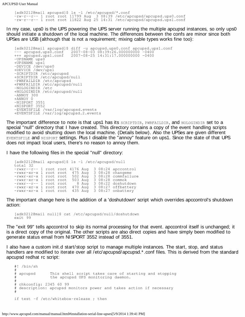
APCUPSD User Manual
http://www.apcupsd.com/manual/manual.html#installation-serial-line-upses[5/9/2014 1:39:41 PM]
[adk0212@mail apcupsd]$ ls -l /etc/apcupsd/*.conf-rw-r--r-- 1 root root 11799 Aug 3 08:39 /etc/apcupsd/apcupsd.ups0.conf-rw-r--r-- 1 root root 11822 Aug 25 14:31 /etc/apcupsd/apcupsd.ups1.conf
In my case, ups0 is the UPS powering the UPS server running the multiple apcupsd instances, so only ups0should initiate a shutdown of the local machine. The differences between the confs are minor since bothUPSes are USB (although that is not a requirement; mixing cable types works fine too):
[adk0212@mail apcupsd]$ diff -u apcupsd.ups0.conf apcupsd.ups1.conf--- apcupsd.ups0.conf 2007-08-03 08:39:26.000000000 -0400+++ apcupsd.ups1.conf 2007-08-25 14:31:17.000000000 -0400-UPSNAME ups0+UPSNAME ups1-DEVICE /dev/ups0+DEVICE /dev/ups1-SCRIPTDIR /etc/apcupsd+SCRIPTDIR /etc/apcupsd/null-PWRFAILDIR /etc/apcupsd+PWRFAILDIR /etc/apcupsd/null-NOLOGINDIR /etc+NOLOGINDIR /etc/apcupsd/null-ANNOY 300+ANNOY 0-NISPORT 3551+NISPORT 3552-EVENTSFILE /var/log/apcupsd.events+EVENTSFILE /var/log/apcupsd.2.events
The important difference to note is that ups1 has its SCRIPTDIR, PWRFAILDIR, and NOLOGINDIR set to aspecial "null" directory that I have created. This directory contains a copy of the event handling scriptsmodified to avoid shutting down the local machine. (Details below). Also the UPSes are given differentEVENTSFILE and NISPORT settings. Plus I disable the "annoy" feature on ups1. Since the state of that UPSdoes not impact local users, there's no reason to annoy them.
I have the following files in the special "null" directory:[adk0212@mail apcupsd]$ ls -l /etc/apcupsd/nulltotal 32-rwxr--r-- 1 root root 4176 Aug 3 08:24 apccontrol-rwxr-xr-x 1 root root 475 Aug 3 08:28 changeme-rwxr-xr-x 1 root root 502 Aug 3 08:28 commfailure-rwxr-xr-x 1 root root 503 Aug 3 08:28 commok-rwxr--r-- 1 root root 8 Aug 3 08:22 doshutdown-rwxr-xr-x 1 root root 470 Aug 3 08:27 offbattery-rwxr-xr-x 1 root root 435 Aug 3 08:27 onbattery
The important change here is the addition of a 'doshutdown' script which overrides apccontrol's shutdownaction:
[adk0212@mail null]$ cat /etc/apcupsd/null/doshutdownexit 99
The "exit 99" tells apccontrol to skip its normal processing for that event. apccontrol itself is unchanged; itis a direct copy of the original. The other scripts are also direct copies and have simply been modified togenerate status email from NISPORT 3552 instead of 3551.
I also have a custom init.d start/stop script to manage multiple instances. The start, stop, and statushandlers are modified to iterate over all /etc/apcupsd/apcupsd.*.conf files. This is derived from the standardapcupsd redhat rc script:
#! /bin/sh## apcupsd This shell script takes care of starting and stopping# the apcupsd UPS monitoring daemon.## chkconfig: 2345 60 99# description: apcupsd monitors power and takes action if necessary#
if test -f /etc/whitebox-release ; then
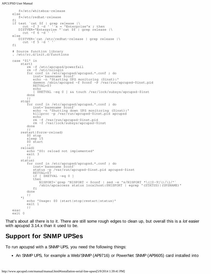
APCUPSD User Manual
http://www.apcupsd.com/manual/manual.html#installation-serial-line-upses[5/9/2014 1:39:41 PM]
f=/etc/whitebox-releaseelse f=/etc/redhat-releasefiif test `cat $f | grep release |\ cut -f 3 -d ' '`x = "Enterprise"x ; then DISTVER="Enterprise "`cat $f | grep release |\ cut -f 6 -d ' '`else DISTVER=`cat /etc/redhat-release | grep release |\ cut -f 5 -d ' '`fi
# Source function library. /etc/rc.d/init.d/functions
case "$1" in start) rm -f /etc/apcupsd/powerfail rm -f /etc/nologin for conf in /etc/apcupsd/apcupsd.*.conf ; do inst=`basename $conf` echo -n "Starting UPS monitoring ($inst):" daemon /sbin/apcupsd -f $conf -P /var/run/apcupsd-$inst.pid RETVAL=$? echo [ $RETVAL -eq 0 ] && touch /var/lock/subsys/apcupsd-$inst done ;; stop) for conf in /etc/apcupsd/apcupsd.*.conf ; do inst=`basename $conf` echo -n "Shutting down UPS monitoring ($inst):" killproc -p /var/run/apcupsd-$inst.pid apcupsd echo rm -f /var/run/apcupsd-$inst.pid rm -f /var/lock/subsys/apcupsd-$inst done ;; restart|force-reload) $0 stop sleep 15 $0 start ;; reload) echo "$0: reload not implemented" exit 3 ;; status) for conf in /etc/apcupsd/apcupsd.*.conf ; do inst=`basename $conf` status -p /var/run/apcupsd-$inst.pid apcupsd-$inst RETVAL=$? if [ $RETVAL -eq 0 ] then NISPORT=`grep ^NISPORT < $conf | sed -e "s/NISPORT *\([0-9]\)/\1/"` /sbin/apcaccess status localhost:$NISPORT | egrep "(STATUS)|(UPSNAME)" fi done ;; *) echo "Usage: $0 {start|stop|restart|status}" exit 1 ;;esacexit 0
That's about all there is to it. There are still some rough edges to clean up, but overall this is a lot easierwith apcupsd 3.14.x than it used to be.
Support for SNMP UPSesTo run apcupsd with a SNMP UPS, you need the following things:
An SNMP UPS, for example a Web/SNMP (AP9716) or PowerNet SNMP (AP9605) card installed into
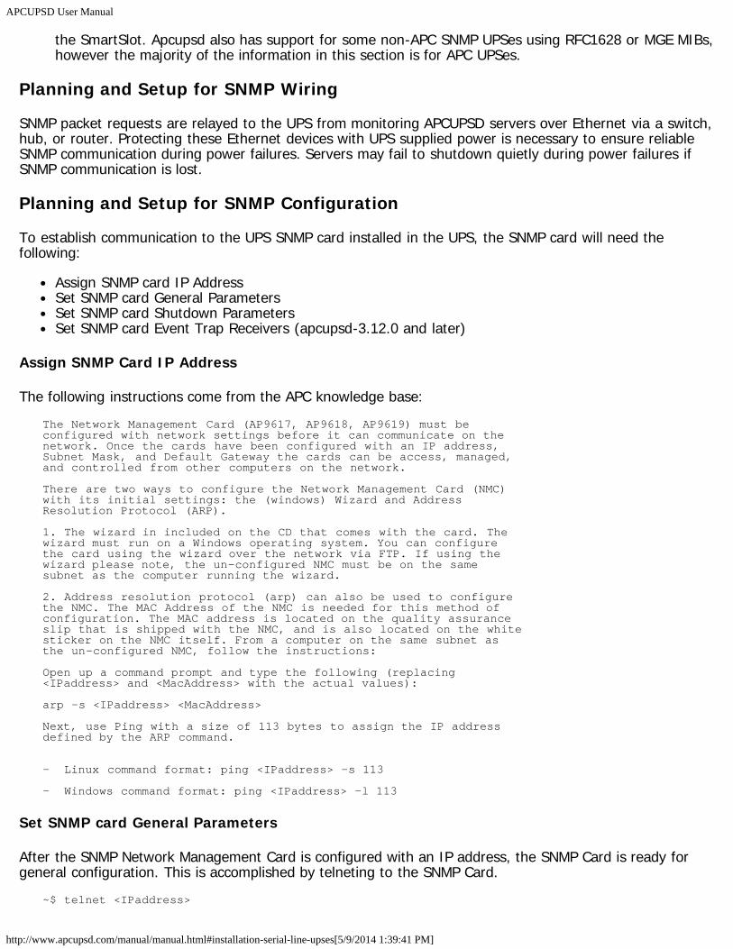
APCUPSD User Manual
http://www.apcupsd.com/manual/manual.html#installation-serial-line-upses[5/9/2014 1:39:41 PM]
the SmartSlot. Apcupsd also has support for some non-APC SNMP UPSes using RFC1628 or MGE MIBs,however the majority of the information in this section is for APC UPSes.
Planning and Setup for SNMP Wiring
SNMP packet requests are relayed to the UPS from monitoring APCUPSD servers over Ethernet via a switch,hub, or router. Protecting these Ethernet devices with UPS supplied power is necessary to ensure reliableSNMP communication during power failures. Servers may fail to shutdown quietly during power failures ifSNMP communication is lost.
Planning and Setup for SNMP Configuration
To establish communication to the UPS SNMP card installed in the UPS, the SNMP card will need thefollowing:
Assign SNMP card IP AddressSet SNMP card General ParametersSet SNMP card Shutdown ParametersSet SNMP card Event Trap Receivers (apcupsd-3.12.0 and later)
Assign SNMP Card IP Address
The following instructions come from the APC knowledge base:The Network Management Card (AP9617, AP9618, AP9619) must beconfigured with network settings before it can communicate on thenetwork. Once the cards have been configured with an IP address,Subnet Mask, and Default Gateway the cards can be access, managed,and controlled from other computers on the network.
There are two ways to configure the Network Management Card (NMC)with its initial settings: the (windows) Wizard and AddressResolution Protocol (ARP).
1. The wizard in included on the CD that comes with the card. Thewizard must run on a Windows operating system. You can configurethe card using the wizard over the network via FTP. If using thewizard please note, the un-configured NMC must be on the samesubnet as the computer running the wizard.
2. Address resolution protocol (arp) can also be used to configurethe NMC. The MAC Address of the NMC is needed for this method ofconfiguration. The MAC address is located on the quality assuranceslip that is shipped with the NMC, and is also located on the whitesticker on the NMC itself. From a computer on the same subnet asthe un-configured NMC, follow the instructions:
Open up a command prompt and type the following (replacing<IPaddress> and <MacAddress> with the actual values):
arp -s <IPaddress> <MacAddress>
Next, use Ping with a size of 113 bytes to assign the IP addressdefined by the ARP command.
- Linux command format: ping <IPaddress> -s 113
- Windows command format: ping <IPaddress> -l 113
Set SNMP card General Parameters
After the SNMP Network Management Card is configured with an IP address, the SNMP Card is ready forgeneral configuration. This is accomplished by telneting to the SNMP Card.
~$ telnet <IPaddress>
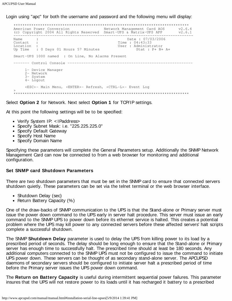
APCUPSD User Manual
http://www.apcupsd.com/manual/manual.html#installation-serial-line-upses[5/9/2014 1:39:41 PM]
Login using "apc" for both the username and password and the following menu will display:*******************************************************************************American Power Conversion Network Management Card AOS v2.6.4(c) Copyright 2004 All Rights Reserved Smart-UPS & Matrix-UPS APP v2.6.1-------------------------------------------------------------------------------Name : Date : 07/03/2006Contact : Time : 04:43:33Location : User : AdministratorUp Time : 0 Days 01 Hours 57 Minutes Stat : P+ N+ A+
Smart-UPS 1000 named : On Line, No Alarms Present
------- Control Console -------------------------------------------------------
1- Device Manager 2- Network 3- System 4- Logout
<ESC>- Main Menu, <ENTER>- Refresh, <CTRL-L>- Event Log>*******************************************************************************
Select Option 2 for Network. Next select Option 1 for TCP/IP settings.
At this point the following settings will be to be specified:
Verify System IP: <IPaddress>Specify Subnet Mask: i.e. "225.225.225.0"Specify Default GatewaySpecify Host NameSpecify Domain Name
Specifying these parameters will complete the General Parameters setup. Additionally the SNMP NetworkManagement Card can now be connected to from a web browser for monitoring and additionalconfiguration.
Set SNMP card Shutdown Parameters
There are two shutdown parameters that must be set in the SNMP card to ensure that connected serversshutdown quietly. These parameters can be set via the telnet terminal or the web browser interface.
Shutdown Delay (sec)Return Battery Capacity (%)
One of the draw-backs of SNMP communication to the UPS is that the Stand-alone or Primary server mustissue the power down command to the UPS early in server halt procedure. This server must issue an earlycommand to the SNMP UPS to power down before its ethernet service is halted. This creates a potentialproblem where the UPS may kill power to any connected servers before these affected servers' halt scriptscomplete a successful shutdown.
The SNMP Shutdown Delay parameter is used to delay the UPS from killing power to its load by aprescribed period of seconds. The delay should be long enough to ensure that the Stand-alone or Primaryserver has enough time to successfully halt. The prescribed time should at least be 180 seconds. Anyadditional computers connected to the SNMP UPS must not be configured to issue the command to initiateUPS power down. These servers can be thought of as secondary stand-alone server. The APCUPSDdaemons of secondary servers should be configured to initiate server halt a prescribed period of timebefore the Primary server issues the UPS power down command.
The Return on Battery Capacity is useful during intermittent sequential power failures. This parameterinsures that the UPS will not restore power to its loads until it has recharged it battery to a prescribed
APCUPSD User Manual
http://www.apcupsd.com/manual/manual.html#installation-serial-line-upses[5/9/2014 1:39:41 PM]
percentage. This parameter should be set to a value greater than value that the APCUPSD daemonsconfigured "BATTERYLEVEL" shutdown of any connected servers. This will ensure that when the UPSrestores power, any additional power failures will successfully re-trigger a server shutdown.
Configure Event Trap Receivers
(Requires apcupsd-3.12.0 and later)
By default, APCUPSD will poll the SNMP UPS card once per minute. In this case, server notification of UPSalarms could potentially be delayed one minute. Event trap catching mitigates this shortcoming. Any UPSalarms are instantly sent to prescribe servers connected SNMP UPS. These servers are referred to as EventTrap Receivers. The SNMP UPS card can be configure to send event traps to a maximum of four receiversthat will "catch" these events.
Event trap receivers IP address can be set using a telnet terminal or web browser interface.
Also, be aware that servers configured to be Event Trap Receivers should have static IP set. Seversobtaining IPs from DHCP server will not catch instantaneous Events if the IP address changes from theaddress set in the SNMP UPS.
Connecting APCUPSD to a SNMP UPS
The previous sections describe configuration of the actual SNMP card. The remaining sections describeconfiguration of the APCUPSD to communicate using SNMP Protocol.
To enable the SNMP support it is enough to configure the correct device in your apcupsd.conf configurationfile. The directive needed for this configuration is:
DEVICE <host>:<port>:<vendor>:<community>
...where the directive is made by four parts. All but the first may be omitted completely or left empty toaccept the default.
host: IP address or DNS hostname of the UPS (required)
port: Remote SNMP port (optional, default: 161)
vendor: The type of SNMP MIB available on the UPS (optional, default: autodetect). Allowable choicesfor vendor are:
APC : APC PowerNet MIB, used on most APC brand UPSesRFC : RFC1628 MIB, used by some non-APC UPSesMGE : MGE MIB, used by many MGE brand UPSesblank : Autodetect
Append "_NOTRAP" to the vendor name to disable SNMP trap catching (ex: "APC_NOTRAP"). SeeSNMP Trap Catching.
community: The read-write community string, usually "private". You can specify a read-onlycommunity string, usually "public", if you do not require killpower support. If the community string isomitted, apcupsd will attempt to autotedect by trying "private" and "public". (optional, default:autodetect).
A NIS Server/Client (Master/Slave) configuration with multiple servers is still applicable. However, analternative configuration is possible with an SNMP enabled UPS. In this arrangement, all connected serverswill be configured as a standalone server. Each will independently communicate to the UPS. One (primary)server will be chosen to manage the task of commanding the UPS to power down. All remaining
APCUPSD User Manual
http://www.apcupsd.com/manual/manual.html#installation-serial-line-upses[5/9/2014 1:39:41 PM]
(secondary) servers will be configured to quietly power down before the primary server issues the UPSpower down command.
Building with SNMP support
Follow the instructions in Building and Installing apcupsd, being sure to include the following options (inaddition to any others you need) on the './configure' line:
./configure --enable-snmp
SNMP Trap Catching
apcupsd-3.11.14 introduces support for SNMP trap catching. Previous versions polled the UPS status onceper minute, leading to significant delays before UPS state changes were recognized. With SNMP traphandling, apcupsd monitors the SNMP trap port and will re-poll the UPS whenever a trap is received. Thishappens, for example, when the UPS switches on or off battery.
In order for this feature to work, you must configure your UPS to deliver traps to the server runningapcupsd. This is generally done by connecting to your SNMP card via a web browser or telnet connection.You will need to enter your server's IP address as a trap receiver and make sure trap delivery is enabled.
Trap catching can lead to problems if you are already running another SNMP trap daemon on your server.Only one daemon can listen to the trap port, so whichever one is started first will succeed and the otherswill fail. Apcupsd will fall back to polling behavior if it is unable to open the trap port. You can also forciblydisable trap catching by appending _NOTRAP to your vendor string in the apcupsd.conf DEVICE directive.
Known Problems
Currently (as of 3.10.0) the code to power off the UPS needs special configuration. The killpower commandfor SNMP UPSes can not be issued during shutdown as typically at some time during shutdown operationsthe network stack is stopped. To overcome this problem it is needed to modify the /etc/rc.d/apcupsdsystem control script to tell apcupsd to issue the power down command (killpower) to the UPS immediatelybefore apcupsd initiates the system shutdown. For this reason it is paramount to set your UPS grace timeto a value greater than 120 seconds to allow for clean shutdown operations before the UPS removes thepower from its plugs. To enable correct shutdown operation during powerdown do the following:
Connect to your Web/SNMP card using your favorite web browser, go to the UPS configuration menuand change the "Shutdown Delay" parameter to 180 seconds or more, depending on how much timeyour system shutdown requires to umount all the filesystems.Option 1 (non-windows) Edit the server halt script. Relocate the ups_kill_power() function higherin the shutdown sequence, primarily before the command to bring down the ethernet service. This isthe preferred method for shutting down the UPS. The UPS will power down after the prescribed "ShutDown Delay" time (in seconds) has elapsed.Option 2 Change /etc/rc.d/apcupsd script adding the --kill-on-powerfail to the apcupsdinvocation. This method is not preferred because the UPS is commanded to power down withoutdelay. This creates the potential for UPS powering down before the server calling for UPS power downcompletes its shutdown. However, in the case of Microsoft Windows OS, this is the only methodavailable for powering down the UPS.Restart your apcupsd
With this setup your UPS operations should be safe.
apcupsd System LoggingThe apcupsd philosophy is that all logging should be done through the syslog facility (see: 'man syslog')
APCUPSD User Manual
http://www.apcupsd.com/manual/manual.html#installation-serial-line-upses[5/9/2014 1:39:41 PM]
This is now implemented with the exceptions that STATUS logging, for compatibility with prior versions isstill done to a file, and EVENTS logging can be directed to a temporary file so that it can be reported by thenetwork information server.
Logging Types
apcupsd splits its logging into four separate types called:
1. DEBUG2. DATA3. STATUS4. EVENTS
Debug logging consists of debug messages. Normally these are turned on only by developers, and currentlythere exist very few of these debug messages.
Data Logging
This feature is somewhat outdated and not often used.
Data logging consists of periodically logging important data concerning the operation of the UPS. For thedefinitive definition of the format, see log_data() in apcreports.c. The format varies according to the UPSmodel and the information available from the UPS.
For UPS models, NBKPRO, SMART, SHARESMART, and MATRIX, the output is written in a format verysimilar to what PowerChute writes. That is:
MinLineVoltage, MaxLineVoltage, OutputVoltage, BatteryVoltage, LineFrequency, LoadPercent,UPSTemperature, AmbientTemperature, Humidity, LineVoltage, BatteryCharge, toggle
Any value that is not supported by your UPS such as AmbientTemperature and Humidity will be blank orpossibly as 0.0. In any case the commas before and after that field will still be output. The toggle valuealternates from 0 to 1 on each line. This was added at user request so that no two adjacent samples areidentical.
An actual example from the log file is:Nov 2 12:43:05 matou apcupsd[23439]: 224.9,227.5,226.2,27.74,50.00,100.0,30.6,,,226.2,50.0,1
Status Logging
Status logging consists of logging all available information known about your UPS as a series of ASCIIrecords. This information is also made available by the apcupsd network information server.
For more details on STATUS logging, see the apcupsd Status Logging section for details.
EVENTS Logging
Events logging consists of logging events as they happen. For example, successful startup, power fail,battery failure, system shutdown, ...
See the Customizing Event Handling section for more details.
Implementation Details
APCUPSD User Manual
http://www.apcupsd.com/manual/manual.html#installation-serial-line-upses[5/9/2014 1:39:41 PM]
In order to ensure that the data logged to syslog() can be directed to different files, I have assignedsyslog() levels to each of our four types of data as follows:
1. DEBUG logging has level LOG_DEBUG2. DATA logging has level LOG_INFO3. STATUS logging has level LOG_NOTICE4. EVENTS logging has levels LOG_WARNING, LOG_ERR, LOG_CRIT, and LOG_ALERT
It should be noted that more work needs to be done on the precise definitions of each of the levels forEVENTS logging. Currently, it is roughly broken down as follows:
LOG_WARNING general information such as startup, etc.
LOG_ERR an error condition detected, e.g. communications problem with the UPS.
LOG_CRIT a serious problem has occurred such as power failure, running on UPS batteries, ...
LOG_ALERT a condition that needs immediate attention such as pending system shutdown, ...
The default Facility for syslog() logging is DAEMON, although this can be changed with the FACILITYdirective in apcupsd.conf. In the following example, we should the facility as local0.
More work needs to be done to the code to ensure that it corresponds to the above levels.
As a practical example of how to setup your syslog() to use the new logging feature, suppose you wish todirect all DATA logging to a file named /var/log/apcupsd.data, all EVENTS to the standard/var/log/messages file (to be mixed with other system messages), and at the same time send all EVENTS to/var/log/apcupsd.events, and finally, you want to send all STATUS logging to the named pipe/var/log/apcupsd.status
First as root, you create the named pipe:mkfifo /var/log/apcupsd.status
Change its permissions as necessary or use the -m option to set them when creating the pipe.
Then you modify your /etc/syslog.conf file to direct the appropriate levels of messages where you wantthem. To accomplish the above, my syslog.conf file looks like:
# exclude all apcupsd info by default*.info;local0.none /var/log/messages
# Everything for apcupsd goes herelocal0.info;local0.!notice /var/log/apcupsd.datalocal0.notice;local0.!warn |/var/log/apcupsd.statuslocal0.warn /var/log/apcupsd.eventslocal0.warn /var/log/messages
The Windows Version of apcupsdThe Windows version of apcupsd has been tested on Win95, Win98, WinMe, WinNT, WinXP, and Win2000systems. This version of apcupsd has been built to run natively on Windows (no Cygwin or other emulationlayer needed). Even though the Win32 version of apcupsd is a port that relies on many Unix features, it isjust the same a true Windows program. When running, it is perfectly integrated with Windows and displaysits icon in the system icon tray, and provides a system tray menu to obtain additional information on howapcupsd is running (status and events dialog boxes).
Once installed apcupsd normally runs as a system service. This means that it is immediately started by theoperating system when the system is booted, and runs in the background even if there is no user logged
APCUPSD User Manual
http://www.apcupsd.com/manual/manual.html#installation-serial-line-upses[5/9/2014 1:39:41 PM]
into the system.
Installing Apcupsd on Windows
Normally, you will install the Windows version of apcupsd from the binaries. Starting with version 3.11.15,the Windows binaries are distributed with a full GUI installer driven by NSIS, the Nullsoft Scriptable InstallSystem (http://nsis.sourceforge.net).
Installation is very simple and straight-forward: Simply double-click the installer executable and follow theinstructions.
Configuring Apcupsd on Windows
If you are installing Apcupsd for the first time, the installer will give you an opportunity to edit theapcupsd.conf configuration file to contain the values appropriate for your site. (Subsequent installations willmaintain your existing apcupsd.conf, so you need not edit it again unless there are new features or syntaxchanges that must be accounted for.)
The default configuration calls for a USB connected UPS. This is the most common connection for modernUPSes, especially those used with Windows computers. All other apcupsd drivers are available (apcsmart,dumb, net, snmp, pcnet) and can be used simply by editing the configuration file UPSCABLE, UPSTYPE, andDEVICE settings as described elsewhere in this manual.
Note that on Windows, serial ports are specified using COM1, COM2, etc. notation instead of the UNIX-style/dev/tty* notation.
Note also if you are using WinNT or Win2000, the operating system may probe the serial port attempting toattach a serial mouse. This will cause apcupsd to be unable to communicate with the serial port. If thishappens, or out of precaution, you can edit the c:\\boot.ini file. Find the line that looks something like thefollowing:
multi(0)disk(0)rdisk(0)partition(1)\WINNT="Windows NT Workstation Version 4.00"
and add the following to the end of the line: /NoSerialMice:COM1 (or COM2 depending on what you want touse). The new line should look similar to...
multi(0)disk(0)rdisk(0)partition(1)\WINNT="Windows NT Workstation Version 4.00" /NoSerialMice:COM1
...where the only thing you have changed is to append to the end of the line. This addition will prevent theoperating system from interfering with apcupsd
Starting Apcupsd on Windows
The installer will give you an opportunity start the Apcupsd service immediately. If you choose to start itmanually, you may do so by selecting the "Start Apcupsd" link from the Start->Programs->Apcupsd folder.
On Windows NT/2000/XP, you may alternatively go to the Control Panel, open the Services folder, selectApcupsd UPS Server, and then click on the Start button as shown below:
If the Services dialog reports a problem, it is normally because your DEVICE statement does not contain thecorrect serial port name.
You probably should also click on the Startup... button to ensure that the correct defaults are set. Thedialogue box that appears should have Startup Type set to Automatic* and **Logon should be set to
APCUPSD User Manual
http://www.apcupsd.com/manual/manual.html#installation-serial-line-upses[5/9/2014 1:39:41 PM]
System Account. If these values are not set correctly by default, please change them otherwise apcupsdwill not work.
For WinXP and Win2K systems, the dialogs are a bit different from those shown here for WinNT, but heconcept is the same. You get to the Services dialog by clicking on: Control Panel -> Administrative Tools ->Component Services. The apcupsd service should appear in the right hand window when you click onServices (Local) in the left hand menu window.
That should complete the installation process. When the system tray icon turns from a question mark into a plug , right click on it and a menu will appear. Select the Events item, and the Events
dialogue box should appear. There should be no error messages. By right clicking again on the system trayplug and selecting the Status item, you can verify that all the values for your UPS are correct.
When the UPS switches to the battery, the battery icon will appear in the system tray. While theUPS is online, if the battery is not at least 99% charged, the plug icon will become a plug with a lightningbolt in the middle to indicate that the battery is charging.
Apctray
Starting with version 3.14.2, the tray icon is provided by a separate program called 'apctray'. This cleanlyseparates the user interface from the daemon (service) and is required for tray icon support on WindowsVista. Note that if you close or disable the tray icon this does not stop or disable the apcupsd service whichwill continue to monitor the UPS and shutdown the computer when appropriate. To stop or disable theservice, use the service control panel.
apctray has the capability of monitoring multiple apcupsd instances using apcupsd's Network InformationServer (NIS). It will create a new icon for each instance being monitored. By default, apctray monitors thelocal apcupsd (localhost on port 3551). To add additional monitors, you can right-click an existing icon andchoose "Add Monitor". To remove a monitor, right-click its icon and choose "Remove Monitor". To changethr settings for an existing monitor (ip address, port, refresh rate), right-click its icon and choose"Configure...".
apctray can be installed standalone (without apcupsd) if you wish to use it only to monitor remote apcupsdinstances. This can be convenient for keeping an eye on a room full of UPSes from your desktop. Downloadand run the normal apcupsd installer and simply uncheck all components except apctray. Then add as manymonitors as you wish as described above.
Testing Apcupsd on Windows
It would be hard to overemphasize the need to do a full testing of your installation of apcupsd as there area number of reasons why it may not behave properly in a real power failure situation.
Please read the Testing Apcupsd section of this document for general instructions on testing the Win32version. However, on Win32 systems, there is no Unix system log file, so if something goes wrong, look inthe file c:\apcupsd\etc\apcupsd\apcupsd.events where apcupsd normally logs its events, and you willgenerally find more detailed information on why the program is not working. The most common cause ofproblems is either improper configuration of the cable type, or an incorrect address for the serial port.Additionally, check the application event log, if you're running a platform that supports it such as Windows2000 or XP.
Upgrading
An upgrade may be accomplished by uninstalling the old version (using the Add/Remove Programs ControlPanel or clicking the "Uninstall Apcupsd" link from Start -> Programs -> Apcupsd. Near the end of theuninstall you will be prompted about removing configuration and event files. You should answer "No" in
APCUPSD User Manual
http://www.apcupsd.com/manual/manual.html#installation-serial-line-upses[5/9/2014 1:39:41 PM]
order to preserve your existing apcupsd.conf file.
After the uninstall completes you may install the new version of Apcupsd as described above. If youpreserved your existing apcupsd.conf file, the new apcupsd.conf will be installed as apcupsd.conf.new.
Post-Installation
After installing apcupsd and before running it, you should check the contents of the config file c:\apcupsd\etc\apcupsd\apcupsd.conf. You will probably need to change your UPSCABLE directive, yourUPSTYPE and possibly your DEVICE directives. Please refer to the configuration section of this manual formore details.
Problem Areas
On some Windows systems, the domain resolution does not seem to work if you have not configured a DNSserver in the Network section of the Control Panel. This problem should be apparent only when running aslave configuration. In this case, when you specify the name of the master in your apcupsd.conf file,apcupsd will be unable to resolve the name to a valid IP address. To circumvent this problem, simply enterthe address as an IP address rather than a hostname, or alternatively, ensure that you have a valid DNSserver configured on your system.
On WinNT, WinXP, and Win2K systems, you can examine the System Applications log to which apcupsdwrites Windows error messages during startup.
Regardless of which Windows system you are running, apcupsd logs most error messages to c:\apcupsd\etc\apcupsd\apcupsd.events. This type error messages such as configuration file not found, etcare written to this file. Note that on some systems (WinXP, possibly others) Apcupsd is unable to write tothis file when running as a service.
Email Notification of Events
It is possible to receive email notification of apcupsd events using some simple Visual Basic scriptscontributed by Ed Dondlinger <[email protected]>. The scripts are automatically installed inthe etc/apcupsd directory of your apcupsd installation but are disabled by default. To enable them, firstopen them in a text editor such as Notepad and edit the USER VARIABLES section to set your emailpreferences including address, server information, etc. Then rename the script files without the *.examplesuffix. Scripts are supplied for onbattery, offbattery, and commfailure events. You can copy the scripts toother filenames and modify the email body text to respond to other events as described in CustomizingEvent Handling.
Killpower under Windows
If your batteries become exhausted during a power failure and you want your machine to automaticallyreboot when the power comes back, it is useful to implement the killpower feature of the UPS whereapcupsd sends the UPS the command to shut off the power. In doing so, the power will be cut to your PCand if your BIOS is properly setup, the machine will automatically reboot when the power comes back. Thisis important for servers.
This feature is implemented on Unix systems by first requesting a system shutdown. As a part of theshutdown, apcupsd is terminated by the system, but the shutdown process executes a script whereapcupsd is recalled after the disks are synced and the machine is idle. Apcupsd then requests the UPS toshut off the power (killpower).
Unfortunately on Windows, there is no such shutdown script that we are aware of and no way for apcupsdto get control after the machine is idled. If this feature is important to you, it is possible to do it by telling
APCUPSD User Manual
http://www.apcupsd.com/manual/manual.html#installation-serial-line-upses[5/9/2014 1:39:41 PM]
apcupsd to immediately issue the killpower command after issuing the shutdown request. The danger indoing so is that if the machine is not sufficiently idled when the killpower takes place, the disks will need tobe rescanned (and there is a possibility of lost data however small). Generally, UPSes have a shutdowngrace period which gives sufficient time for the OS to shutdown before the power is cut.
To implement this feature, you need to add the -p option to the apcupsd command line that is executed bythe system. Currently the procedure is manual. You do so by editing the registry and changing the line:
c:\apcupsd\apcupsd.exe /service
found under the key:HKEY_LOCAL_MACHINE Software\Microsoft\Windows\CurrentVersion\RunServices
toc:\apcupsd\apcupsd.exe /service -p
If you have a Smart UPS, you can configure the kill power grace period, and you might want to set it to 3minutes. If you have a dumb UPS, there is no grace period and you should not use this procedure. If youhave a Back-UPS CS or ES, these UPSes generally have a fixed grace period of 2 minutes, which is probablysufficient.
Power Down During Shutdown
Our philosophy is to shutdown a computer but not to power it down itself (as opposed to having the UPScut the power as described above). That is we prefer to idle a computer but leave it running. This has theadvantage that in a power fail situation, if the killpower function described above does not work, thecomputer will continue to draw down the batteries and the UPS will hopefully shutoff before the power isrestore thus permitting an automatic reboot.
Nevertheless some people prefer to do a full power down. To do so, you might want to get a copy ofPsShutdown, which does have a power down option. You can find it and a lot more useful software at:http://technet.microsoft.com/en-us/sysinternals/bb897541.aspx. To use their shutdown program rather thanthe apcupsd supplied version, you simply edit:
c:\apcupsd\etc\apcupsd\apccontrol
with any text editor and change our calls to shutdown to psshutdown.
Command Line Options Specific to the Windows Version
These options are not normally seen or used by the user, and are documented here only for informationpurposes. At the current time, to change the default options, you must either manually run apcupsd or youmust manually edit the system registry and modify the appropriate entries.
In order to avoid option clashes between the options necessary for apcupsd to run on Windows and thestandard apcupsd options, all Windows specific options are signaled with a forward slash character (/),while as usual, the standard apcupsd options are signaled with a minus (-), or a minus minus (--). All thestandard apcupsd options can be used on the Windows version. In addition, the following Windows onlyoptions are implemented:
/service Start apcupsd as a service/run Run the apcupsd application/install Install apcupsd as a service in the system registry/remove Uninstall apcupsd from the system registry/about Show the apcupsd about dialogue box
APCUPSD User Manual
http://www.apcupsd.com/manual/manual.html#installation-serial-line-upses[5/9/2014 1:39:41 PM]
/kill Stop any running apcupsd/help Show the apcupsd help dialogue box
It is important to note that under normal circumstances the user should never need to use these options asthey are normally handled by the system automatically once apcupsd is installed. However, you may notethese options in some of the .pif files that have been created for your use.
Installation: Serial-Line UPSesOverview of Serial-Interface UPSes
If you have a UPS that communicates via serial port, you need to do two things before you can even thinkabout configuring the software. First, you need to figure out whether it's a dumb (voltage-signalling) UPS orspeaks the apcsmart protocol. Second, if you have an interface cable from APC, you need to figure out whatkind it is. If you don't have such a cable, you need to build one. A straight-through serial cable won't work.
According to Bill Marr the Belkin F5U109, also sold as F5U409 also works with apcupsd for kernel versions2.4.25 or higher and kernels 2.6.1 and higher. These newer kernels are needed to have the patch thatmakes the mct_u232 (Magic Control Technology) module and other adapters work with RS-232 devices thatdo not assert the CTS signal.
Connecting a Serial-Line UPS to a USB Port
By using a special adaptor, you can connect your serial-line UPS to a USB port. If you would like to free upyour serial port and connect your existing serial port UPS to a USB port, it is possible if you have one of thelater kernels. You simply get a serial to USB adapter that is supported by the kernel, plug it in and makeone minor change to your apcupsd.conf file and away you go. (Kern adds: Thanks to Joe Acosta forpointing this out to me.)
The device that Joe Acosta and Kern are using is IOgear GUC232A USB 2 serial adapter. Bill Marr informsus that it also works with a Back-UPS Pro 650 and the 940-0095B cable.
At Kern's site, running Red Hat 7.1 with kernel 2.4.9-12, he simply changed his /etc/apcupsd/apcupsd.confconfiguration line to be:
DEVICE /dev/ttyUSB0
Depending on whether or not you have hotplug working, you may need to explicitly load the kernelmodules usbserial and pl2303. In Kern's case, this was not necessary.
Testing Serial-Line UPSes
If you have a serial-line UPS, there are some tests you should run before the general ones described in theTesting Apcupsd section.
To test your computer's connection with a serial-line UPS, you first need to establish that the serial line isfunctioning, and then that the UPS is responding to commands. This can be a bit tricky, especially with adumb voltage-signalling interface, because it is completely quiescent when there are no commands beingpassed, and the command repertoire doesn't include any self-tests.
Because it is easy to configure a serial cable incorrectly in such a way as to cause premature shutdowns ofthe UPS power, we strongly recommend, especially for voltage- signaling (dumb) UPSes, that you do mostof the initial testing with your computer plugged into the wall rather than your UPS. Thus if the UPS poweris suddenly shut off, your computer will continue to run. We also recommend using safe-apccontrol asdescribed below, until you are sure that the signaling is correct.
APCUPSD User Manual
http://www.apcupsd.com/manual/manual.html#installation-serial-line-upses[5/9/2014 1:39:41 PM]
Also note that if you launch the execution of apcupsd while your voltage-signaling UPS is on battery power,it is very likely that your UPS will immediately shut off the power. This is due to the initialization of theserial port line signals, which often looks to the UPS like a shutdown command.
Finally, double-check the state of your cabling and UPS indicator lights frequently during testing. Forvoltage-signaling UPSes, apcupsd is not currently able to detect whether or not the serial cable isconnected. In addition, some simple signaling UPSes with certain cable combinations are not able to detectthe low battery condition. For more details please see Voltage Signalling Features Supported by Apcupsd forVarious Cables.
Establishing Serial Port Connection
Once you have compiled, installed, and invoked apcupsd, you should wait to allow apcupsd to configureitself and establish contact with the UPS.
If you see a message similar to the following about 30 seconds after starting apcupsd...apcupsd FATAL ERROR in apcserial.c at line 156PANIC! Cannot communicate with UPS via serial port.
it means that apcupsd tried for about 30 seconds to establish contact with the UPS via the serial port, butwas unable to do so. Before continuing, you must correct this problem. Some of the possible sources of theproblem are:
You have not configured the correct serial port name on the DEVICE directive in your apcupsdconfiguration file.The serial port that you have chosen has logins enabled. You must disable logins on that port,otherwise, the system prevents apcupsd from using it. Normally, the file /etc/inittab specifies the portsfor which a getty process is started (on Sun machines, the serial port program equivalent to getty iscalled ttymon). You must disable this for the port that you wish to use.Make sure you are doing your testing as root otherwise, you may have permissions problemsaccessing the serial port.You may have cabling problems, either with an incorrect cable, or the incorrect cable specificationdirective in the configuration file.You may have a problem with the /etc/apcupsd/acpupsd.conf file. For example, check that you havespecified the correct type of UPS and the correct networking directives. For more details, see the AfterInstallation section.If you have a SmartUPS 5000 RM 15U or similar model, that comes with a "Web/SNMP managementcard" in one of the "Smart Slots", this card may interfere with the serial port operation. If you arehaving problems, please remove this card and try again. Supposedly V3.0 of the card firmware hasbeen corrected to properly release the serial port.Ensure that you have no other programs that are using the serial port. One user reported that he hadproblems because the serial port mouse (gpm) was using the same port as apcupsd. This causesintermittent seemingly random problems.Try connecting your UPS to another machine. If it works, then you probably have a bad serial portcard. As unlikely as this may sound, at least two of our users have had to replace bad serial portcards.Try doing an 'lsof /dev/ttyS0' where you replace the /dev/ttyS0 with your serial port name. If youget no output, the port is free (or there is no physical port). If you get output, then another programis using the port, and you should see which one.Try doing a 'dmesg | grep tty'. This may show you if a program has grabbed the port. (Thanks toJoe Acosta for the suggestion.)If all else fails, make sure your system is configured for serial port support.
The first thing to do is to look at your log file, usually /var/log/messages because apcupsd writes moredetailed information to the log file whenever there is an error.
APCUPSD User Manual
http://www.apcupsd.com/manual/manual.html#installation-serial-line-upses[5/9/2014 1:39:41 PM]
If you have a UPS that uses apcsmart protocol, you can manually test the serial communications with theUPS by starting a serial port communications program (such as minicom, tip, or cu) with the settings 24008N1 (2400 baud, 8 data bits, no parity, 1 stop bit). Be extremely careful what you send to your UPS ascertain characters may cause it to power down or may even cause damage to the UPS. Try sending anupper case Y to the UPS (without a return at the end). It should respond with SM. If this is not the case,review the possible problems listed above. If you fat finger the Y and enter y instead, no cause for alarm,you will simply get the APC copyright notice.
Once you are sure that serial port communications is working, proceed to the next test.
Once you have established serial communications
Once you have established that apcupsd can talk to the UPS over the serial part, go do the series offunctional tests described in the main Testing section (see Testing Apcupsd).
Troubleshooting Serial Line communications
The most frequently encountered problem with voltage-signalling UPSes (e.g. BackUPS 650) is that youhave incorrectly specified which cable is being used. All cables furnished by APC have the cable numberstamped on the side of the computer connector end of the cable. Using this number with apcupsd willnormally work fine. If you do not know what cable you have, you can use the apctest program to determinethe type of the cable.
For simple signaling UPSes, you should not use simple in the cable specification (i.e. UPSCABLE simple)unless you have made the cable yourself according to the wiring diagram given in the cables chapter of thismanual.
Bizarre Intermittent Behavior:
In one case, a user reported that he received random incorrect values from the UPS in the status output. Itturned out that gpm, the mouse control program for command windows, was using the serial port withoutusing the standard Unix locking mechanism. As a consequence, both apcupsd and gpm were reading theserial port. Please ensure that if you are running gpm that it is not configured with a serial port mouse onthe same serial port.
CablesYou can either use the cable that came with your UPS (the easiest if we support it) or you can make yourown cable. We recommend that you obtain a supported cable directly from APC.
If you already have an APC cable, you can determine what kind it is by examining the flat sides of the twoconnectors where you will find the cable number embossed into the plastic. It is generally on one side ofthe male connector.
To make your own cable you must first know whether you have a UPS that speaks the apcsmart protocol ora "dumb" UPS that uses serial port line voltage signalling.
If you have an smart UPS, and you build your own cable, build a Smart-Custom cable (see Smart-CustomCable for SmartUPSes). If you have a voltage-signalling or dumb UPS, build a Simple-Custom cable (seeSimple-Custom Voltage-Signalling Cable for "dumb" UPSes). If you have a BackUPS CS with a RJ45connector, you can build your own Custom-RJ45 cable (see Custom-RJ45 Smart Signalling Cable forBackUPS CS Models).
Smart-Custom Cable for SmartUPSes
APCUPSD User Manual
http://www.apcupsd.com/manual/manual.html#installation-serial-line-upses[5/9/2014 1:39:41 PM]
You do not have this cable unless you built it yourself. The Smart-Custom cable is not an APC product. SMART-CUSTOM CABLE
Signal Computer UPS DB9F DB9M RxD 2 -------------------- 2 TxD Send TxD 3 -------------------- 1 RxD Receive GND 5 -------------------- 9 Ground
When using this cable with apcupsd specify the following in apcupsd.conf:UPSCABLE smartUPSTYPE apcsmartDEVICE /dev/ttyS0 (or whatever your serial port is)
If you have an OS that requires DCD or RTS to be set before you can receive input, you might try buildingthe standard APC Smart 940-0024C cable listed below (see 940-0024C Cable Wiring).
Simple-Custom Voltage-Signalling Cable for "dumb" UPSes
You do not have this cable unless you built it yourself. The Simple-Custom cable is not an APC product.
For "dumb" UPSes using voltage signalling, if you are going to build your own cable, we recommend tomake the cable designed by the apcupsd team as follows:
SIMPLE-CUSTOM CABLE
Signal Computer UPS DB9F 4.7K ohm DB9M DTR 4 --[####]--* DTR set to +5V by Apcupsd | CTS 8 ----------*--------- 5 Low Battery GND 5 -------------------- 4 Ground DCD 1 -------------------- 2 On Battery RTS 7 -------------------- 1 Kill UPS Power
List of components one needs to make the Simple cable:
1. One (1) male DB9 connector, use solder type connector only.2. One (1) female DB9/25F connector, use solder type connector only.3. One (1) 4.7K ohm 1/4 watt 5% resistor.4. rosin core solder.5. three (3) to five (5) feet of 22AWG multi-stranded four or more conductor cable.
Assembly instructions:
1. Solder the resistor into pin 4 of the female DB9 connector.2. Next bend the resistor so that it connects to pin 8 of the female DB9 connector.3. Pin 8 on the female connector is also wired to pin 5 on the male DB9 connector. Solder both ends.4. Solder the other pins, pin 5 on the female DB9 to pin 4 on the male connector; pin 1 on the female
connector to pin 2 on the male connector; and pin 7 on the female connector to pin 1 on the maleconnector.
5. Double check your work.
We use the DTR (pin 4 on the female connector) as our +5 volts power for the circuit. It is used as the Vccpull-up voltage for testing the outputs on any "UPS by APC" in voltage-signalling mode. This cable may notwork on a BackUPS Pro if the default communications are in apcsmart mode. This cable is also valid for useon a ShareUPS BASIC Port. It is reported to work on SmartUPSes, however the Smart Cable describedabove is preferred.
To have a better idea of what is going on inside apcupsd, for the SIMPLE cable apcupsd reads three signalsand sets three:
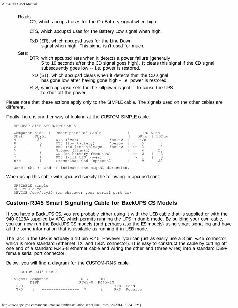
APCUPSD User Manual
http://www.apcupsd.com/manual/manual.html#installation-serial-line-upses[5/9/2014 1:39:41 PM]
Reads:CD, which apcupsd uses for the On Battery signal when high.
CTS, which apcupsd uses for the Battery Low signal when high.
RxD (SR), which apcupsd uses for the Line Downsignal when high. This signal isn't used for much.
Sets:DTR, which apcupsd sets when it detects a power failure (generally
5 to 10 seconds after the CD signal goes high). It clears this signal if the CD signalsubsequently goes low -- i.e. power is restored.
TxD (ST), which apcupsd clears when it detects that the CD signalhas gone low after having gone high - i.e. power is restored.
RTS, which apcupsd sets for the killpower signal -- to cause the UPSto shut off the power.
Please note that these actions apply only to the SIMPLE cable. The signals used on the other cables aredifferent.
Finally, here is another way of looking at the CUSTOM-SIMPLE cable:APCUPSD SIMPLE-CUSTOM CABLE
Computer Side | Description of Cable | UPS SideDB9f | DB25f | | DB9m | DB25m4 | 20 | DTR (5vcc) *below | n/c |8 | 5 | CTS (low battery) *below | <- 5 | 72 | 3 | RxD (no line voltage) *below | <- 3 | 25 | 7 | Ground (Signal) | 4 | 201 | 8 | CD (on battery from UPS) | <- 2 | 37 | 4 | RTS (kill UPS power) | -> 1 | 8n/c | 1 | Frame/Case Gnd (optional) | 9 | 22
Note: the <- and -> indicate the signal direction.
When using this cable with apcupsd specify the following in apcupsd.conf:UPSCABLE simpleUPSTYPE dumbDEVICE /dev/ttyS0 (or whatever your serial port is)
Custom-RJ45 Smart Signalling Cable for BackUPS CS Models
If you have a BackUPS CS, you are probably either using it with the USB cable that is supplied or with the940-0128A supplied by APC, which permits running the UPS in dumb mode. By building your own cable,you can now run the BackUPS CS models (and perhaps also the ES models) using smart signalling and haveall the same information that is available as running it in USB mode.
The jack in the UPS is actually a 10 pin RJ45. However, you can just as easily use a 8 pin RJ45 connector,which is more standard (ethernet TX, and ISDN connector). It is easy to construct the cable by cutting offone end of a standard RJ45-8 ethernet cable and wiring the other end (three wires) into a standard DB9Ffemale serial port connector.
Below, you will find a diagram for the CUSTOM-RJ45 cable: CUSTOM-RJ45 CABLE
Signal Computer UPS UPS DB9F RJ45-8 RJ45-10 RxD 2 ---------------- 1 2 TxD Send TxD 3 ---------------- 7 8 RxD Receive
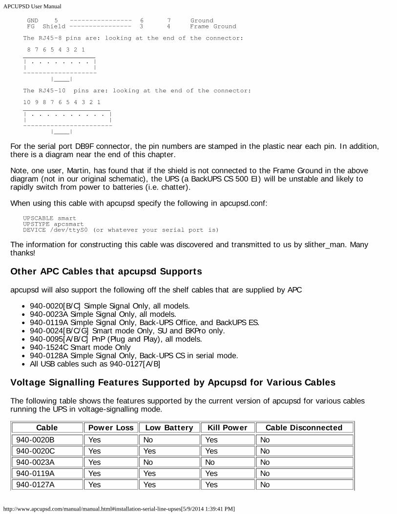
APCUPSD User Manual
http://www.apcupsd.com/manual/manual.html#installation-serial-line-upses[5/9/2014 1:39:41 PM]
GND 5 ---------------- 6 7 Ground FG Shield ---------------- 3 4 Frame Ground
The RJ45-8 pins are: looking at the end of the connector:
8 7 6 5 4 3 2 1___________________| . . . . . . . . || |------------------- |____|
The RJ45-10 pins are: looking at the end of the connector:
10 9 8 7 6 5 4 3 2 1_______________________| . . . . . . . . . . || |----------------------- |____|
For the serial port DB9F connector, the pin numbers are stamped in the plastic near each pin. In addition,there is a diagram near the end of this chapter.
Note, one user, Martin, has found that if the shield is not connected to the Frame Ground in the abovediagram (not in our original schematic), the UPS (a BackUPS CS 500 EI) will be unstable and likely torapidly switch from power to batteries (i.e. chatter).
When using this cable with apcupsd specify the following in apcupsd.conf:UPSCABLE smartUPSTYPE apcsmartDEVICE /dev/ttyS0 (or whatever your serial port is)
The information for constructing this cable was discovered and transmitted to us by slither_man. Manythanks!
Other APC Cables that apcupsd Supports
apcupsd will also support the following off the shelf cables that are supplied by APC
940-0020[B/C] Simple Signal Only, all models.940-0023A Simple Signal Only, all models.940-0119A Simple Signal Only, Back-UPS Office, and BackUPS ES.940-0024[B/C/G] Smart mode Only, SU and BKPro only.940-0095[A/B/C] PnP (Plug and Play), all models.940-1524C Smart mode Only940-0128A Simple Signal Only, Back-UPS CS in serial mode.All USB cables such as 940-0127[A/B]
Voltage Signalling Features Supported by Apcupsd for Various Cables
The following table shows the features supported by the current version of apcupsd for various cablesrunning the UPS in voltage-signalling mode.
Cable Power Loss Low Battery Kill Power Cable Disconnected940-0020B Yes No Yes No940-0020C Yes Yes Yes No940-0023A Yes No No No940-0119A Yes Yes Yes No940-0127A Yes Yes Yes No
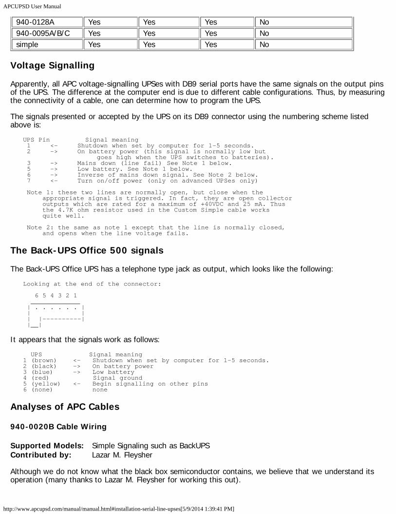
APCUPSD User Manual
http://www.apcupsd.com/manual/manual.html#installation-serial-line-upses[5/9/2014 1:39:41 PM]
940-0128A Yes Yes Yes No940-0095A/B/C Yes Yes Yes Nosimple Yes Yes Yes No
Voltage Signalling
Apparently, all APC voltage-signalling UPSes with DB9 serial ports have the same signals on the output pinsof the UPS. The difference at the computer end is due to different cable configurations. Thus, by measuringthe connectivity of a cable, one can determine how to program the UPS.
The signals presented or accepted by the UPS on its DB9 connector using the numbering scheme listedabove is:
UPS Pin Signal meaning 1 <- Shutdown when set by computer for 1-5 seconds. 2 -> On battery power (this signal is normally low but goes high when the UPS switches to batteries). 3 -> Mains down (line fail) See Note 1 below. 5 -> Low battery. See Note 1 below. 6 -> Inverse of mains down signal. See Note 2 below. 7 <- Turn on/off power (only on advanced UPSes only)
Note 1: these two lines are normally open, but close when the appropriate signal is triggered. In fact, they are open collector outputs which are rated for a maximum of +40VDC and 25 mA. Thus the 4.7K ohm resistor used in the Custom Simple cable works quite well.
Note 2: the same as note 1 except that the line is normally closed, and opens when the line voltage fails.
The Back-UPS Office 500 signals
The Back-UPS Office UPS has a telephone type jack as output, which looks like the following:Looking at the end of the connector:
6 5 4 3 2 1 _____________ | . . . . . . | | | | |----------| |__|
It appears that the signals work as follows: UPS Signal meaning1 (brown) <- Shutdown when set by computer for 1-5 seconds.2 (black) -> On battery power3 (blue) -> Low battery4 (red) Signal ground5 (yellow) <- Begin signalling on other pins6 (none) none
Analyses of APC Cables
940-0020B Cable Wiring
Supported Models: Simple Signaling such as BackUPSContributed by: Lazar M. Fleysher
Although we do not know what the black box semiconductor contains, we believe that we understand itsoperation (many thanks to Lazar M. Fleysher for working this out).
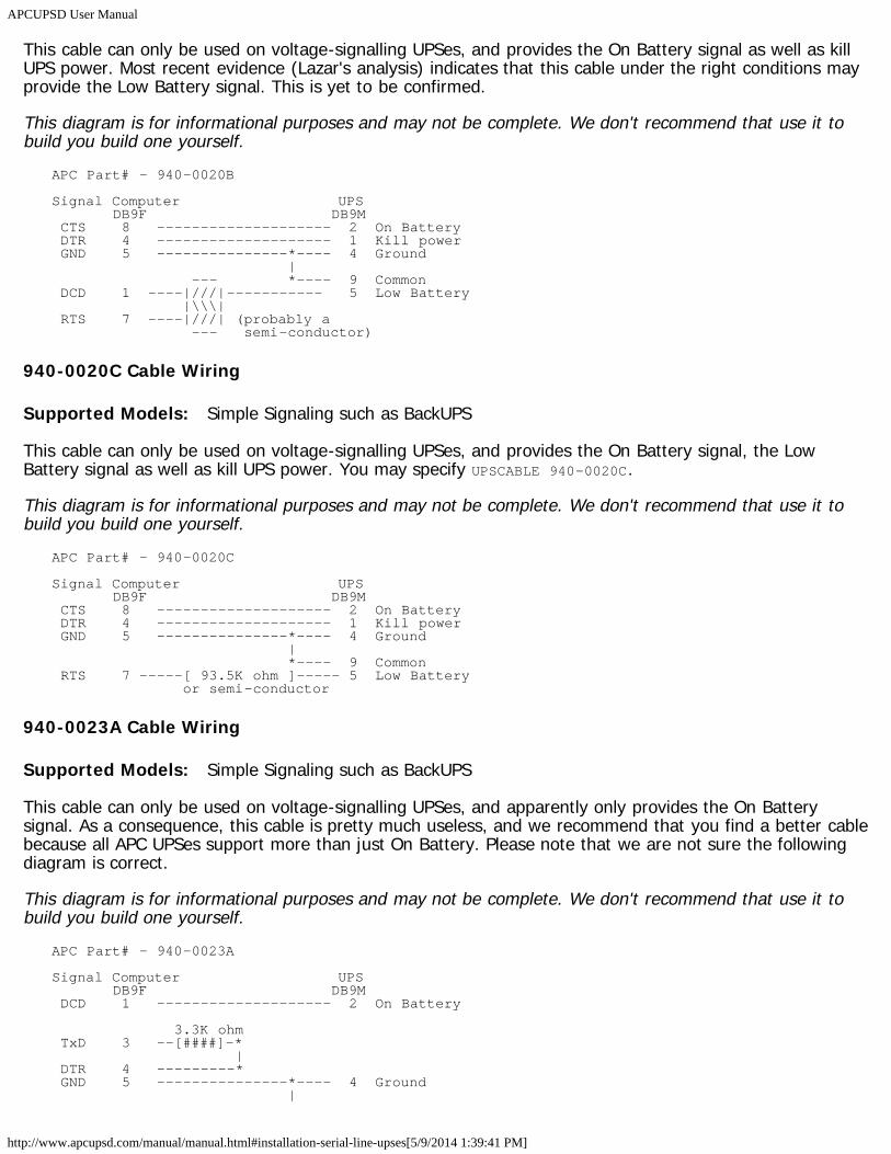
APCUPSD User Manual
http://www.apcupsd.com/manual/manual.html#installation-serial-line-upses[5/9/2014 1:39:41 PM]
This cable can only be used on voltage-signalling UPSes, and provides the On Battery signal as well as killUPS power. Most recent evidence (Lazar's analysis) indicates that this cable under the right conditions mayprovide the Low Battery signal. This is yet to be confirmed.
This diagram is for informational purposes and may not be complete. We don't recommend that use it tobuild you build one yourself.
APC Part# - 940-0020B
Signal Computer UPS DB9F DB9M CTS 8 -------------------- 2 On Battery DTR 4 -------------------- 1 Kill power GND 5 ---------------*---- 4 Ground | --- *---- 9 Common DCD 1 ----|///|----------- 5 Low Battery |\\\| RTS 7 ----|///| (probably a --- semi-conductor)
940-0020C Cable Wiring
Supported Models: Simple Signaling such as BackUPS
This cable can only be used on voltage-signalling UPSes, and provides the On Battery signal, the LowBattery signal as well as kill UPS power. You may specify UPSCABLE 940-0020C.
This diagram is for informational purposes and may not be complete. We don't recommend that use it tobuild you build one yourself.
APC Part# - 940-0020C
Signal Computer UPS DB9F DB9M CTS 8 -------------------- 2 On Battery DTR 4 -------------------- 1 Kill power GND 5 ---------------*---- 4 Ground | *---- 9 Common RTS 7 -----[ 93.5K ohm ]----- 5 Low Battery or semi-conductor
940-0023A Cable Wiring
Supported Models: Simple Signaling such as BackUPS
This cable can only be used on voltage-signalling UPSes, and apparently only provides the On Batterysignal. As a consequence, this cable is pretty much useless, and we recommend that you find a better cablebecause all APC UPSes support more than just On Battery. Please note that we are not sure the followingdiagram is correct.
This diagram is for informational purposes and may not be complete. We don't recommend that use it tobuild you build one yourself.
APC Part# - 940-0023A
Signal Computer UPS DB9F DB9M DCD 1 -------------------- 2 On Battery
3.3K ohm TxD 3 --[####]-* | DTR 4 ---------* GND 5 ---------------*---- 4 Ground |
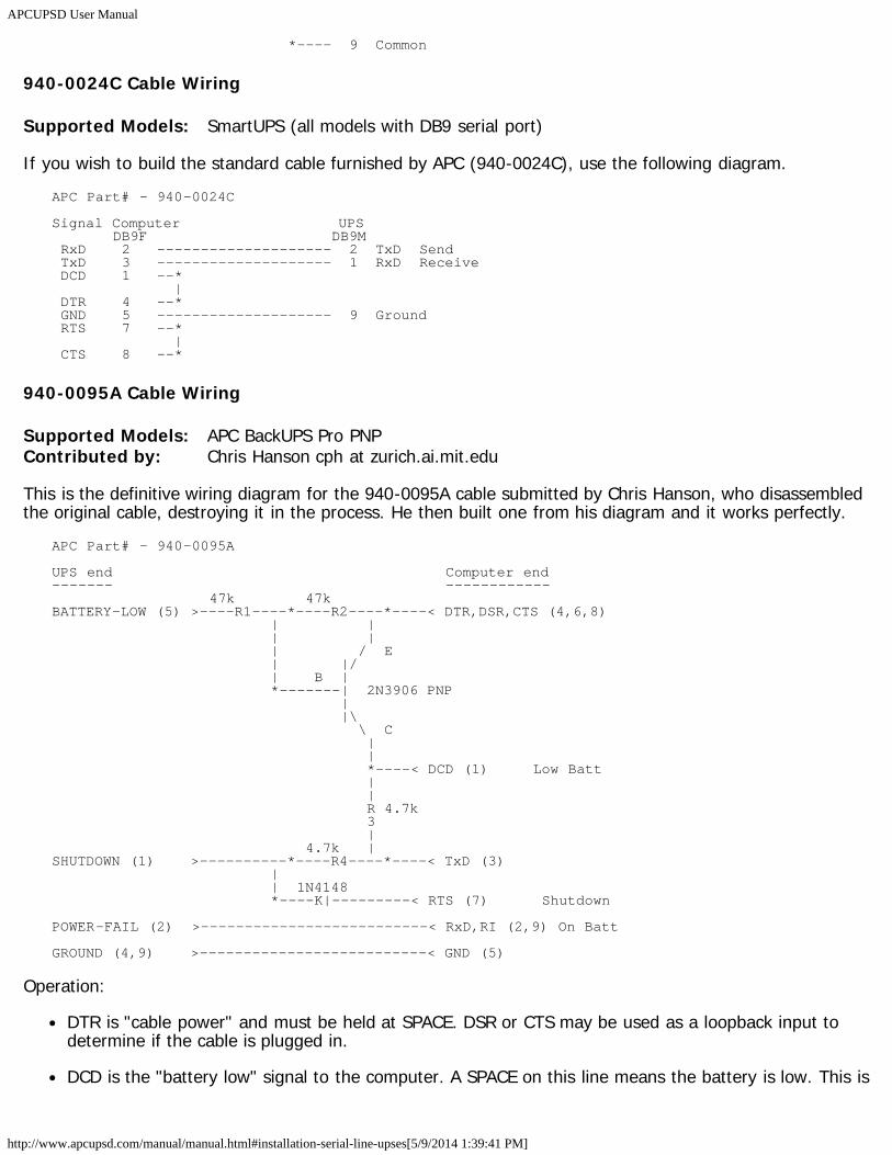
APCUPSD User Manual
http://www.apcupsd.com/manual/manual.html#installation-serial-line-upses[5/9/2014 1:39:41 PM]
*---- 9 Common
940-0024C Cable Wiring
Supported Models: SmartUPS (all models with DB9 serial port)
If you wish to build the standard cable furnished by APC (940-0024C), use the following diagram.APC Part# - 940-0024C
Signal Computer UPS DB9F DB9M RxD 2 -------------------- 2 TxD Send TxD 3 -------------------- 1 RxD Receive DCD 1 --* | DTR 4 --* GND 5 -------------------- 9 Ground RTS 7 --* | CTS 8 --*
940-0095A Cable Wiring
Supported Models: APC BackUPS Pro PNPContributed by: Chris Hanson cph at zurich.ai.mit.edu
This is the definitive wiring diagram for the 940-0095A cable submitted by Chris Hanson, who disassembledthe original cable, destroying it in the process. He then built one from his diagram and it works perfectly.
APC Part# - 940-0095A
UPS end Computer end------- ------------ 47k 47kBATTERY-LOW (5) >----R1----*----R2----*----< DTR,DSR,CTS (4,6,8) | | | | | / E | |/ | B | *-------| 2N3906 PNP | |\ \ C | | *----< DCD (1) Low Batt | | R 4.7k 3 | 4.7k |SHUTDOWN (1) >----------*----R4----*----< TxD (3) | | 1N4148 *----K|---------< RTS (7) Shutdown
POWER-FAIL (2) >--------------------------< RxD,RI (2,9) On Batt
GROUND (4,9) >--------------------------< GND (5)
Operation:
DTR is "cable power" and must be held at SPACE. DSR or CTS may be used as a loopback input todetermine if the cable is plugged in.
DCD is the "battery low" signal to the computer. A SPACE on this line means the battery is low. This is
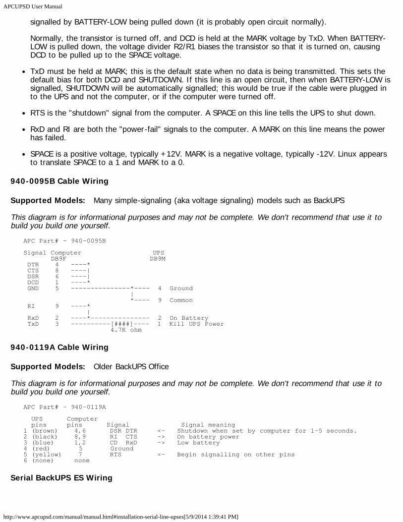
APCUPSD User Manual
http://www.apcupsd.com/manual/manual.html#installation-serial-line-upses[5/9/2014 1:39:41 PM]
signalled by BATTERY-LOW being pulled down (it is probably open circuit normally).
Normally, the transistor is turned off, and DCD is held at the MARK voltage by TxD. When BATTERY-LOW is pulled down, the voltage divider R2/R1 biases the transistor so that it is turned on, causingDCD to be pulled up to the SPACE voltage.
TxD must be held at MARK; this is the default state when no data is being transmitted. This sets thedefault bias for both DCD and SHUTDOWN. If this line is an open circuit, then when BATTERY-LOW issignalled, SHUTDOWN will be automatically signalled; this would be true if the cable were plugged into the UPS and not the computer, or if the computer were turned off.
RTS is the "shutdown" signal from the computer. A SPACE on this line tells the UPS to shut down.
RxD and RI are both the "power-fail" signals to the computer. A MARK on this line means the powerhas failed.
SPACE is a positive voltage, typically +12V. MARK is a negative voltage, typically -12V. Linux appearsto translate SPACE to a 1 and MARK to a 0.
940-0095B Cable Wiring
Supported Models: Many simple-signaling (aka voltage signaling) models such as BackUPS
This diagram is for informational purposes and may not be complete. We don't recommend that use it tobuild you build one yourself.
APC Part# - 940-0095B
Signal Computer UPS DB9F DB9M DTR 4 ----* CTS 8 ----| DSR 6 ----| DCD 1 ----* GND 5 ---------------*---- 4 Ground | *---- 9 Common RI 9 ----* | RxD 2 ----*--------------- 2 On Battery TxD 3 ----------[####]---- 1 Kill UPS Power 4.7K ohm
940-0119A Cable Wiring
Supported Models: Older BackUPS Office
This diagram is for informational purposes and may not be complete. We don't recommend that use it tobuild you build one yourself.
APC Part# - 940-0119A
UPS Computer pins pins Signal Signal meaning1 (brown) 4,6 DSR DTR <- Shutdown when set by computer for 1-5 seconds.2 (black) 8,9 RI CTS -> On battery power3 (blue) 1,2 CD RxD -> Low battery4 (red) 5 Ground5 (yellow) 7 RTS <- Begin signalling on other pins6 (none) none
Serial BackUPS ES Wiring
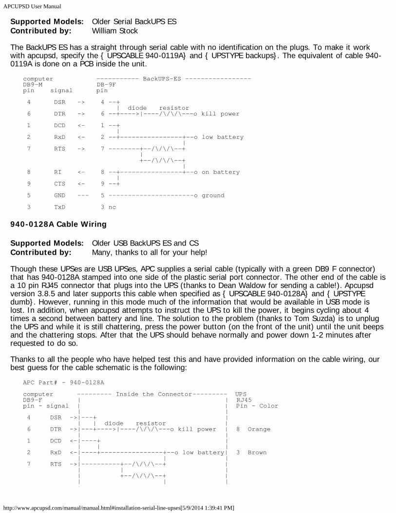
APCUPSD User Manual
http://www.apcupsd.com/manual/manual.html#installation-serial-line-upses[5/9/2014 1:39:41 PM]
Supported Models: Older Serial BackUPS ESContributed by: William Stock
The BackUPS ES has a straight through serial cable with no identification on the plugs. To make it workwith apcupsd, specify the { UPSCABLE 940-0119A} and { UPSTYPE backups}. The equivalent of cable 940-0119A is done on a PCB inside the unit.
computer ----------- BackUPS-ES -----------------DB9-M DB-9Fpin signal pin
4 DSR -> 4 --+ | diode resistor 6 DTR -> 6 --+---->|----/\/\/\---o kill power
1 DCD <- 1 --+ | 2 RxD <- 2 --+----------------+--o low battery | 7 RTS -> 7 --------+--/\/\/\--+ | +--/\/\/\--+ | 8 RI <- 8 --+----------------+--o on battery | 9 CTS <- 9 --+
5 GND --- 5 ----------------------o ground
3 TxD 3 nc
940-0128A Cable Wiring
Supported Models: Older USB BackUPS ES and CSContributed by: Many, thanks to all for your help!
Though these UPSes are USB UPSes, APC supplies a serial cable (typically with a green DB9 F connector)that has 940-0128A stamped into one side of the plastic serial port connector. The other end of the cable isa 10 pin RJ45 connector that plugs into the UPS (thanks to Dean Waldow for sending a cable!). Apcupsdversion 3.8.5 and later supports this cable when specified as { UPSCABLE 940-0128A} and { UPSTYPEdumb}. However, running in this mode much of the information that would be available in USB mode islost. In addition, when apcupsd attempts to instruct the UPS to kill the power, it begins cycling about 4times a second between battery and line. The solution to the problem (thanks to Tom Suzda) is to unplugthe UPS and while it is still chattering, press the power button (on the front of the unit) until the unit beepsand the chattering stops. After that the UPS should behave normally and power down 1-2 minutes afterrequested to do so.
Thanks to all the people who have helped test this and have provided information on the cable wiring, ourbest guess for the cable schematic is the following:
APC Part# - 940-0128A
computer --------- Inside the Connector--------- UPSDB9-F | | RJ45pin - signal | | Pin - Color | | 4 DSR ->|---+ | | | diode resistor | 6 DTR ->|---+---->|----/\/\/\---o kill power | 8 Orange | | 1 DCD <-|----+ | | | | 2 RxD <-|----+----------------+--o low battery| 3 Brown | | | 7 RTS ->|----------+--/\/\/\--+ | | | | | +--/\/\/\--+ | | | |
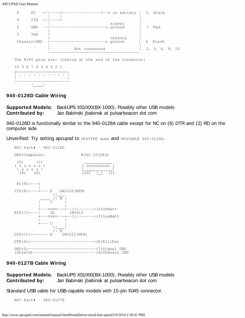
APCUPSD User Manual
http://www.apcupsd.com/manual/manual.html#installation-serial-line-upses[5/9/2014 1:39:41 PM]
8 RI <-|----+----------------+--o on battery | 2 Black | | | 9 CTS <-|----+ | | signal | 5 GND --|-----------------------o ground | 7 Red | | 3 TxD | | | chassis | Chassis/GND |-----------------------o ground | 4 Black | | | Not connected | 1, 5, 6, 9, 10 --------------------------------------
The RJ45 pins are: looking at the end of the connector:
10 9 8 7 6 5 4 3 2 1_______________________| . . . . . . . . . . || |----------------------- |____|
940-0128D Cable Wiring
Supported Models: BackUPS XS1000(BX-1000), Possibly other USB modelsContributed by: Jan Babinski jbabinsk at pulsarbeacon dot com
940-0128D is functionally similar to the 940-0128A cable except for NC on (6) DTR and (2) RD on thecomputer side.
Unverified: Try setting apcupsd to UPSTYPE dumb and UPSCABLE 940-0128A.APC Part# - 940-0128D
DB9(Computer) RJ45-10(UPS)
(5) (1) ____________( o o o o o ) [ oooooooooo ] \ o o o o / [____________] (9) (6) (10) [_] (1)
RI(9)<---+ |CTS(8)<---+--- E 2N2222(NPN) \|___ ____ /| B | | C | | | +---vvvv---+--[>|------<(2)OnBattRTS(7)>---| 2k 1N5819 +---vvvv---+--[>|------<(3)LowBatt | | +--- C | \|___| /| BDCD(1)<------- E 2N2222(NPN)
DTR(4)>-------------------------->(8)KillPwr
GND(5)----------------------------(7)Signal GND(Shield)--------------------------(4)Chassis GND
940-0127B Cable Wiring
Supported Models: BackUPS XS1000(BX-1000), Possibly other USB modelsContributed by: Jan Babinski jbabinsk at pulsarbeacon dot com
Standard USB cable for USB-capable models with 10-pin RJ45 connector.APC Part# - 940-0127B
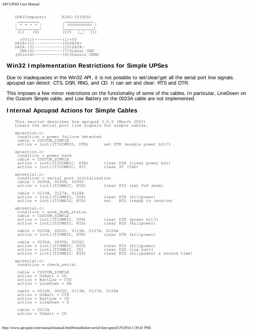
APCUPSD User Manual
http://www.apcupsd.com/manual/manual.html#installation-serial-line-upses[5/9/2014 1:39:41 PM]
USB(Computer) RJ45-10(UPS) _________ ____________| = = = = | [ oooooooooo ]|_________| [____________] (1) (4) (10) [_] (1)
+5V(1)-----------(1)+5VDATA+(2)-----------(9)DATA+DATA-(3)-----------(10)DATA- GND(4)-----------(7)Signal GND(Shield)-----------(4)Chassis GRND
Win32 Implementation Restrictions for Simple UPSes
Due to inadequacies in the Win32 API, it is not possible to set/clear/get all the serial port line signals.apcupsd can detect: CTS, DSR, RNG, and CD. It can set and clear: RTS and DTR.
This imposes a few minor restrictions on the functionality of some of the cables. In particular, LineDown onthe Custom Simple cable, and Low Battery on the 0023A cable are not implemented.
Internal Apcupsd Actions for Simple CablesThis section describes how apcupsd 3.8.5 (March 2002)treats the serial port line signals for simple cables.
apcaction.c: condition = power failure detected cable = CUSTOM_SIMPLE action = ioctl(TIOCMBIS, DTR) set DTR (enable power bit?)
apcaction.c: condition = power back cable = CUSTOM_SIMPLE action = ioctl(TIOCMBIC, DTR) clear DTR (clear power bit) action = ioctl(TIOCMBIC, ST) clear ST (TxD)
apcserial.c: condition = serial port initialization cable = 0095A, 0095B, 0095C action = ioctl(TIOMBIC, RTS) clear RTS (set PnP mode)
cable = 0119A, 0127A, 0128A action = ioctl(TIOMBIC, DTR) clear DTR (killpower) action = ioctl(TIOMBIS, RTS) set RTS (ready to receive)
apcserial.c: condition = save_dumb_status cable = CUSTOM_SIMPLE action = ioctl(TIOMBIC, DTR) clear DTR (power bit?) action = ioctl(TIOMBIC, RTS) clear RTS (killpower)
cable = 0020B, 0020C, 0119A, 0127A, 0128A action = ioctl(TIOMBIC, DTR) clear DTR (killpower)
cable = 0095A, 0095B, 0095C action = ioctl(TIOMBIC, RTS) clear RTS (killpower) action = ioctl(TIOMBIC, CD) clear DCD (low batt) action = ioctl(TIOMBIC, RTS) clear RTS (killpower) a second time!
apcserial.c: condition = check_serial
cable = CUSTOM_SIMPLE action = OnBatt = CD action = BattLow = CTS action = LineDown = SR
cable = 0020B, 0020C, 0119A, 0127A, 0128A action = OnBatt = CTS action = BattLow = CD action = LineDown = 0
cable = 0023A action = Onbatt = CD
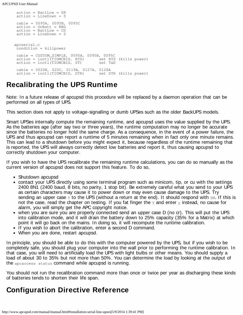
APCUPSD User Manual
http://www.apcupsd.com/manual/manual.html#installation-serial-line-upses[5/9/2014 1:39:41 PM]
action = BattLow = SR action = LineDown = 0
cable = 0095A, 0095B, 0095C action = OnBatt = RNG action = BattLow = CD action = LineDown = 0
apcserial.c condition = killpower
cable = CUSTOM_SIMPLE, 0095A, 0095B, 0095C action = ioctl(TIOMCBIS, RTS) set RTS (kills power) action = ioctl(TIOMCBIS, ST) set TxD
cable = 0020B, 020C, 0119A, 0127A, 0128A action = ioctl(TIOMCBIS, DTR) set DTR (kills power)
Recalibrating the UPS RuntimeNote: In a future release of apcupsd this procedure will be replaced by a daemon operation that can beperformed on all types of UPS.
This section does not apply to voltage-signalling or dumb UPSes such as the older BackUPS models.
Smart UPSes internally compute the remaining runtime, and apcupsd uses the value supplied by the UPS.As the batteries age (after say two or three years), the runtime computation may no longer be accuratesince the batteries no longer hold the same charge. As a consequence, in the event of a power failure, theUPS and thus apcupsd can report a runtime of 5 minutes remaining when in fact only one minute remains.This can lead to a shutdown before you might expect it, because regardless of the runtime remaining thatis reported, the UPS will always correctly detect low batteries and report it, thus causing apcupsd tocorrectly shutdown your computer.
If you wish to have the UPS recalibrate the remaining runtime calculations, you can do so manually as thecurrent version of apcupsd does not support this feature. To do so,
Shutdown apcupsdcontact your UPS directly using some terminal program such as minicom, tip, or cu with the settings2400 8N1 (2400 baud, 8 bits, no parity, 1 stop bit). Be extremely careful what you send to your UPSas certain characters may cause it to power down or may even cause damage to the UPS. Trysending an upper case Y to the UPS (without a return at the end). It should respond with SM. If this isnot the case, read the chapter on testing. If you fat finger the Y and enter y instead, no cause foralarm, you will simply get the APC copyright notice.when you are sure you are properly connected send an upper case D (no cr). This will put the UPSinto calibration mode, and it will drain the battery down to 25% capacity (35% for a Matrix) at whichpoint it will go back on the mains. In doing so, it will recompute the runtime calibration.If you wish to abort the calibration, enter a second D command.When you are done, restart apcupsd.
In principle, you should be able to do this with the computer powered by the UPS, but if you wish to becompletely safe, you should plug your computer into the wall prior to performing the runtime calibration. Inthat case, you will need to artificially load the UPS with light bulbs or other means. You should supply aload of about 30 to 35% but not more than 50%. You can determine the load by looking at the output ofthe apcaccess status command while apcupsd is running.
You should not run the recalibration command more than once or twice per year as discharging these kindsof batteries tends to shorten their life span.
Configuration Directive Reference
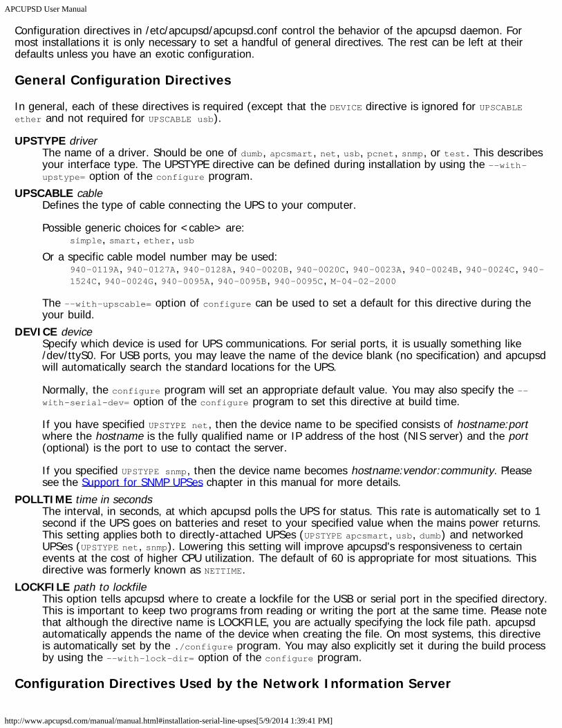
APCUPSD User Manual
http://www.apcupsd.com/manual/manual.html#installation-serial-line-upses[5/9/2014 1:39:41 PM]
Configuration directives in /etc/apcupsd/apcupsd.conf control the behavior of the apcupsd daemon. Formost installations it is only necessary to set a handful of general directives. The rest can be left at theirdefaults unless you have an exotic configuration.
General Configuration Directives
In general, each of these directives is required (except that the DEVICE directive is ignored for UPSCABLEether and not required for UPSCABLE usb).
UPSTYPE driverThe name of a driver. Should be one of dumb, apcsmart, net, usb, pcnet, snmp, or test. This describesyour interface type. The UPSTYPE directive can be defined during installation by using the --with-upstype= option of the configure program.
UPSCABLE cableDefines the type of cable connecting the UPS to your computer.
Possible generic choices for <cable> are:simple, smart, ether, usb
Or a specific cable model number may be used:940-0119A, 940-0127A, 940-0128A, 940-0020B, 940-0020C, 940-0023A, 940-0024B, 940-0024C, 940-1524C, 940-0024G, 940-0095A, 940-0095B, 940-0095C, M-04-02-2000
The --with-upscable= option of configure can be used to set a default for this directive during theyour build.
DEVICE deviceSpecify which device is used for UPS communications. For serial ports, it is usually something like/dev/ttyS0. For USB ports, you may leave the name of the device blank (no specification) and apcupsdwill automatically search the standard locations for the UPS.
Normally, the configure program will set an appropriate default value. You may also specify the --with-serial-dev= option of the configure program to set this directive at build time.
If you have specified UPSTYPE net, then the device name to be specified consists of hostname:portwhere the hostname is the fully qualified name or IP address of the host (NIS server) and the port(optional) is the port to use to contact the server.
If you specified UPSTYPE snmp, then the device name becomes hostname:vendor:community. Pleasesee the Support for SNMP UPSes chapter in this manual for more details.
POLLTIME time in secondsThe interval, in seconds, at which apcupsd polls the UPS for status. This rate is automatically set to 1second if the UPS goes on batteries and reset to your specified value when the mains power returns.This setting applies both to directly-attached UPSes (UPSTYPE apcsmart, usb, dumb) and networkedUPSes (UPSTYPE net, snmp). Lowering this setting will improve apcupsd's responsiveness to certainevents at the cost of higher CPU utilization. The default of 60 is appropriate for most situations. Thisdirective was formerly known as NETTIME.
LOCKFILE path to lockfileThis option tells apcupsd where to create a lockfile for the USB or serial port in the specified directory.This is important to keep two programs from reading or writing the port at the same time. Please notethat although the directive name is LOCKFILE, you are actually specifying the lock file path. apcupsdautomatically appends the name of the device when creating the file. On most systems, this directiveis automatically set by the ./configure program. You may also explicitly set it during the build processby using the --with-lock-dir= option of the configure program.
Configuration Directives Used by the Network Information Server
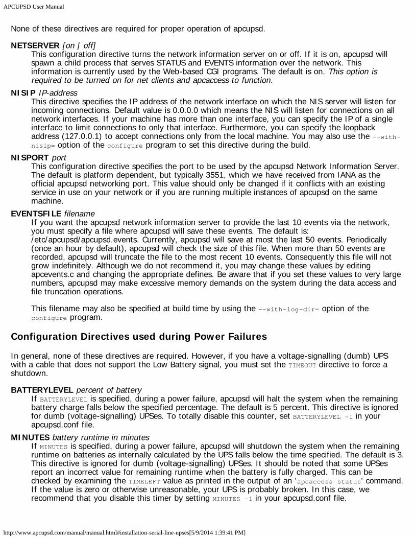
APCUPSD User Manual
http://www.apcupsd.com/manual/manual.html#installation-serial-line-upses[5/9/2014 1:39:41 PM]
None of these directives are required for proper operation of apcupsd.
NETSERVER [on | off]This configuration directive turns the network information server on or off. If it is on, apcupsd willspawn a child process that serves STATUS and EVENTS information over the network. Thisinformation is currently used by the Web-based CGI programs. The default is on. This option isrequired to be turned on for net clients and apcaccess to function.
NISIP IP-addressThis directive specifies the IP address of the network interface on which the NIS server will listen forincoming connections. Default value is 0.0.0.0 which means the NIS will listen for connections on allnetwork interfaces. If your machine has more than one interface, you can specify the IP of a singleinterface to limit connections to only that interface. Furthermore, you can specify the loopbackaddress (127.0.0.1) to accept connections only from the local machine. You may also use the --with-nisip= option of the configure program to set this directive during the build.
NISPORT portThis configuration directive specifies the port to be used by the apcupsd Network Information Server.The default is platform dependent, but typically 3551, which we have received from IANA as theofficial apcupsd networking port. This value should only be changed if it conflicts with an existingservice in use on your network or if you are running multiple instances of apcupsd on the samemachine.
EVENTSFILE filenameIf you want the apcupsd network information server to provide the last 10 events via the network,you must specify a file where apcupsd will save these events. The default is:/etc/apcupsd/apcupsd.events. Currently, apcupsd will save at most the last 50 events. Periodically(once an hour by default), apcupsd will check the size of this file. When more than 50 events arerecorded, apcupsd will truncate the file to the most recent 10 events. Consequently this file will notgrow indefinitely. Although we do not recommend it, you may change these values by editingapcevents.c and changing the appropriate defines. Be aware that if you set these values to very largenumbers, apcupsd may make excessive memory demands on the system during the data access andfile truncation operations.
This filename may also be specified at build time by using the --with-log-dir= option of theconfigure program.
Configuration Directives used during Power Failures
In general, none of these directives are required. However, if you have a voltage-signalling (dumb) UPSwith a cable that does not support the Low Battery signal, you must set the TIMEOUT directive to force ashutdown.
BATTERYLEVEL percent of batteryIf BATTERYLEVEL is specified, during a power failure, apcupsd will halt the system when the remainingbattery charge falls below the specified percentage. The default is 5 percent. This directive is ignoredfor dumb (voltage-signalling) UPSes. To totally disable this counter, set BATTERYLEVEL -1 in yourapcupsd.conf file.
MINUTES battery runtime in minutesIf MINUTES is specified, during a power failure, apcupsd will shutdown the system when the remainingruntime on batteries as internally calculated by the UPS falls below the time specified. The default is 3.This directive is ignored for dumb (voltage-signalling) UPSes. It should be noted that some UPSesreport an incorrect value for remaining runtime when the battery is fully charged. This can bechecked by examining the TIMELEFT value as printed in the output of an 'apcaccess status' command.If the value is zero or otherwise unreasonable, your UPS is probably broken. In this case, werecommend that you disable this timer by setting MINUTES -1 in your apcupsd.conf file.
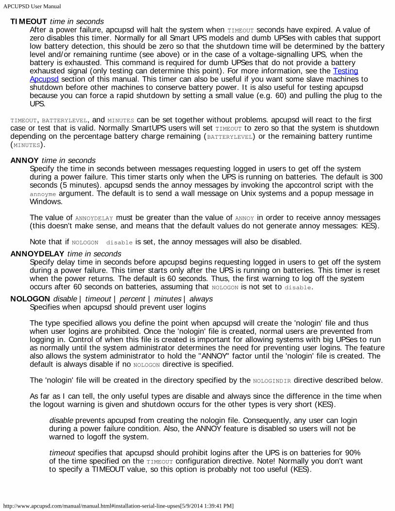
APCUPSD User Manual
http://www.apcupsd.com/manual/manual.html#installation-serial-line-upses[5/9/2014 1:39:41 PM]
TIMEOUT time in secondsAfter a power failure, apcupsd will halt the system when TIMEOUT seconds have expired. A value ofzero disables this timer. Normally for all Smart UPS models and dumb UPSes with cables that supportlow battery detection, this should be zero so that the shutdown time will be determined by the batterylevel and/or remaining runtime (see above) or in the case of a voltage-signalling UPS, when thebattery is exhausted. This command is required for dumb UPSes that do not provide a batteryexhausted signal (only testing can determine this point). For more information, see the TestingApcupsd section of this manual. This timer can also be useful if you want some slave machines toshutdown before other machines to conserve battery power. It is also useful for testing apcupsdbecause you can force a rapid shutdown by setting a small value (e.g. 60) and pulling the plug to theUPS.
TIMEOUT, BATTERYLEVEL, and MINUTES can be set together without problems. apcupsd will react to the firstcase or test that is valid. Normally SmartUPS users will set TIMEOUT to zero so that the system is shutdowndepending on the percentage battery charge remaining (BATTERYLEVEL) or the remaining battery runtime(MINUTES).
ANNOY time in secondsSpecify the time in seconds between messages requesting logged in users to get off the systemduring a power failure. This timer starts only when the UPS is running on batteries. The default is 300seconds (5 minutes). apcupsd sends the annoy messages by invoking the apccontrol script with theannoyme argument. The default is to send a wall message on Unix systems and a popup message inWindows.
The value of ANNOYDELAY must be greater than the value of ANNOY in order to receive annoy messages(this doesn't make sense, and means that the default values do not generate annoy messages: KES).
Note that if NOLOGON disable is set, the annoy messages will also be disabled.ANNOYDELAY time in seconds
Specify delay time in seconds before apcupsd begins requesting logged in users to get off the systemduring a power failure. This timer starts only after the UPS is running on batteries. This timer is resetwhen the power returns. The default is 60 seconds. Thus, the first warning to log off the systemoccurs after 60 seconds on batteries, assuming that NOLOGON is not set to disable.
NOLOGON disable | timeout | percent | minutes | alwaysSpecifies when apcupsd should prevent user logins
The type specified allows you define the point when apcupsd will create the 'nologin' file and thuswhen user logins are prohibited. Once the 'nologin' file is created, normal users are prevented fromlogging in. Control of when this file is created is important for allowing systems with big UPSes to runas normally until the system administrator determines the need for preventing user logins. The featurealso allows the system administrator to hold the "ANNOY" factor until the 'nologin' file is created. Thedefault is always disable if no NOLOGON directive is specified.
The 'nologin' file will be created in the directory specified by the NOLOGINDIR directive described below.
As far as I can tell, the only useful types are disable and always since the difference in the time whenthe logout warning is given and shutdown occurs for the other types is very short (KES).
disable prevents apcupsd from creating the nologin file. Consequently, any user can loginduring a power failure condition. Also, the ANNOY feature is disabled so users will not bewarned to logoff the system.
timeout specifies that apcupsd should prohibit logins after the UPS is on batteries for 90%of the time specified on the TIMEOUT configuration directive. Note! Normally you don't wantto specify a TIMEOUT value, so this option is probably not too useful (KES).
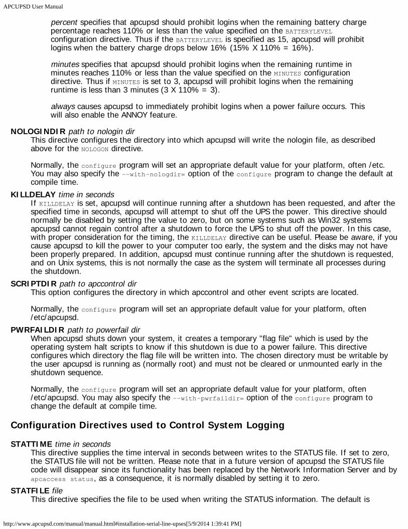
APCUPSD User Manual
http://www.apcupsd.com/manual/manual.html#installation-serial-line-upses[5/9/2014 1:39:41 PM]
percent specifies that apcupsd should prohibit logins when the remaining battery chargepercentage reaches 110% or less than the value specified on the BATTERYLEVELconfiguration directive. Thus if the BATTERYLEVEL is specified as 15, apcupsd will prohibitlogins when the battery charge drops below 16% (15% X 110% = 16%).
minutes specifies that apcupsd should prohibit logins when the remaining runtime inminutes reaches 110% or less than the value specified on the MINUTES configurationdirective. Thus if MINUTES is set to 3, apcupsd will prohibit logins when the remainingruntime is less than 3 minutes (3 X 110% = 3).
always causes apcupsd to immediately prohibit logins when a power failure occurs. Thiswill also enable the ANNOY feature.
NOLOGINDIR path to nologin dirThis directive configures the directory into which apcupsd will write the nologin file, as describedabove for the NOLOGON directive.
Normally, the configure program will set an appropriate default value for your platform, often /etc.You may also specify the --with-nologdir= option of the configure program to change the default atcompile time.
KILLDELAY time in secondsIf KILLDELAY is set, apcupsd will continue running after a shutdown has been requested, and after thespecified time in seconds, apcupsd will attempt to shut off the UPS the power. This directive shouldnormally be disabled by setting the value to zero, but on some systems such as Win32 systemsapcupsd cannot regain control after a shutdown to force the UPS to shut off the power. In this case,with proper consideration for the timing, the KILLDELAY directive can be useful. Please be aware, if youcause apcupsd to kill the power to your computer too early, the system and the disks may not havebeen properly prepared. In addition, apcupsd must continue running after the shutdown is requested,and on Unix systems, this is not normally the case as the system will terminate all processes duringthe shutdown.
SCRIPTDIR path to apccontrol dirThis option configures the directory in which apccontrol and other event scripts are located.
Normally, the configure program will set an appropriate default value for your platform, often/etc/apcupsd.
PWRFAILDIR path to powerfail dirWhen apcupsd shuts down your system, it creates a temporary "flag file" which is used by theoperating system halt scripts to know if this shutdown is due to a power failure. This directiveconfigures which directory the flag file will be written into. The chosen directory must be writable bythe user apcupsd is running as (normally root) and must not be cleared or unmounted early in theshutdown sequence.
Normally, the configure program will set an appropriate default value for your platform, often/etc/apcupsd. You may also specify the --with-pwrfaildir= option of the configure program tochange the default at compile time.
Configuration Directives used to Control System Logging
STATTIME time in secondsThis directive supplies the time interval in seconds between writes to the STATUS file. If set to zero,the STATUS file will not be written. Please note that in a future version of apcupsd the STATUS filecode will disappear since its functionality has been replaced by the Network Information Server and byapcaccess status, as a consequence, it is normally disabled by setting it to zero.
STATFILE fileThis directive specifies the file to be used when writing the STATUS information. The default is
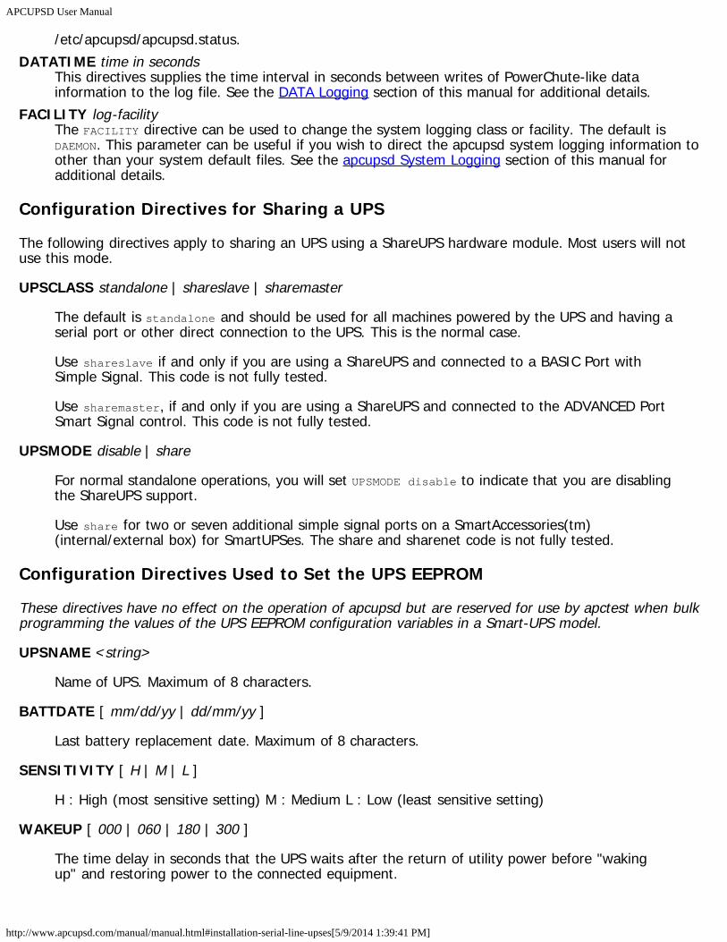
APCUPSD User Manual
http://www.apcupsd.com/manual/manual.html#installation-serial-line-upses[5/9/2014 1:39:41 PM]
/etc/apcupsd/apcupsd.status.DATATIME time in seconds
This directives supplies the time interval in seconds between writes of PowerChute-like datainformation to the log file. See the DATA Logging section of this manual for additional details.
FACILITY log-facilityThe FACILITY directive can be used to change the system logging class or facility. The default isDAEMON. This parameter can be useful if you wish to direct the apcupsd system logging information toother than your system default files. See the apcupsd System Logging section of this manual foradditional details.
Configuration Directives for Sharing a UPS
The following directives apply to sharing an UPS using a ShareUPS hardware module. Most users will notuse this mode.
UPSCLASS standalone | shareslave | sharemaster
The default is standalone and should be used for all machines powered by the UPS and having aserial port or other direct connection to the UPS. This is the normal case.
Use shareslave if and only if you are using a ShareUPS and connected to a BASIC Port withSimple Signal. This code is not fully tested.
Use sharemaster, if and only if you are using a ShareUPS and connected to the ADVANCED PortSmart Signal control. This code is not fully tested.
UPSMODE disable | share
For normal standalone operations, you will set UPSMODE disable to indicate that you are disablingthe ShareUPS support.
Use share for two or seven additional simple signal ports on a SmartAccessories(tm)(internal/external box) for SmartUPSes. The share and sharenet code is not fully tested.
Configuration Directives Used to Set the UPS EEPROM
These directives have no effect on the operation of apcupsd but are reserved for use by apctest when bulkprogramming the values of the UPS EEPROM configuration variables in a Smart-UPS model.
UPSNAME <string>
Name of UPS. Maximum of 8 characters.
BATTDATE [ mm/dd/yy | dd/mm/yy ]
Last battery replacement date. Maximum of 8 characters.
SENSITIVITY [ H | M | L ]
H : High (most sensitive setting) M : Medium L : Low (least sensitive setting)
WAKEUP [ 000 | 060 | 180 | 300 ]
The time delay in seconds that the UPS waits after the return of utility power before "wakingup" and restoring power to the connected equipment.
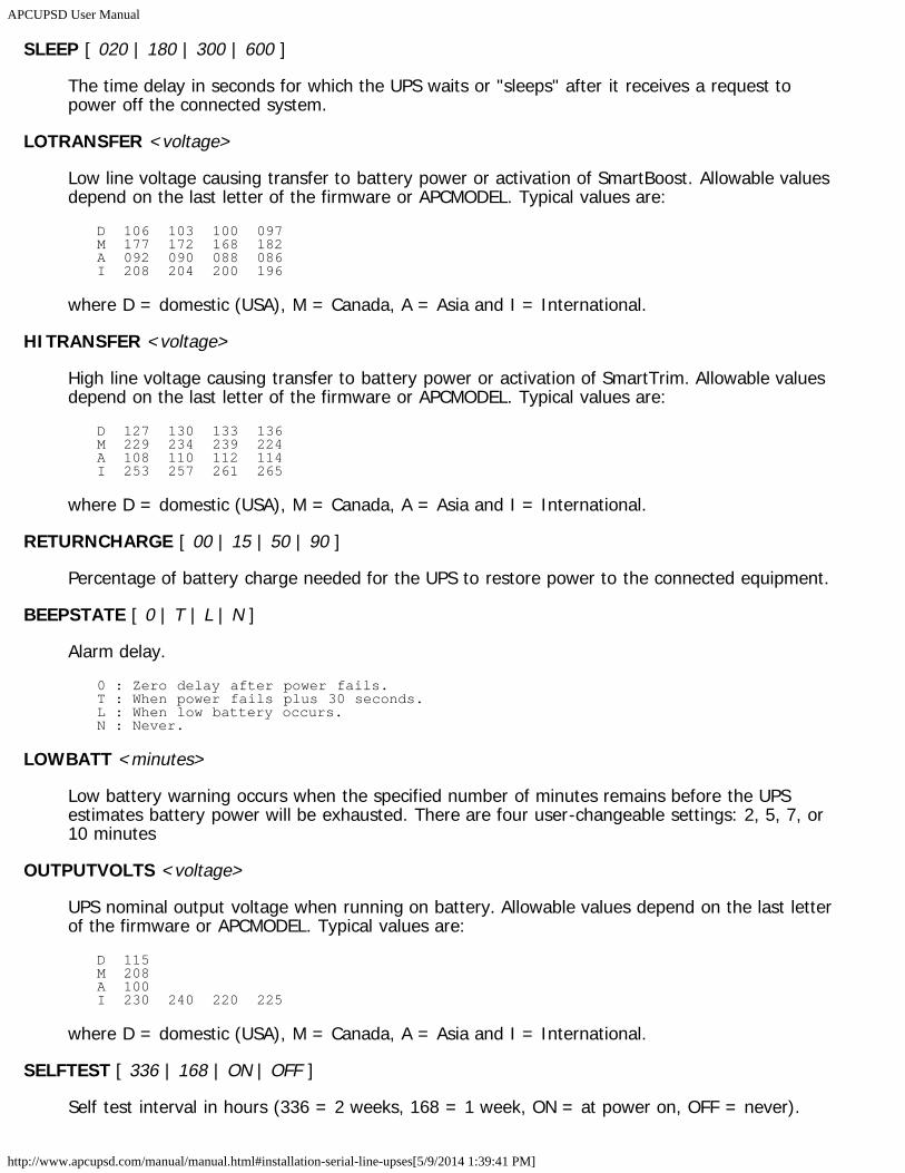
APCUPSD User Manual
http://www.apcupsd.com/manual/manual.html#installation-serial-line-upses[5/9/2014 1:39:41 PM]
SLEEP [ 020 | 180 | 300 | 600 ]
The time delay in seconds for which the UPS waits or "sleeps" after it receives a request topower off the connected system.
LOTRANSFER <voltage>
Low line voltage causing transfer to battery power or activation of SmartBoost. Allowable valuesdepend on the last letter of the firmware or APCMODEL. Typical values are:
D 106 103 100 097M 177 172 168 182A 092 090 088 086I 208 204 200 196
where D = domestic (USA), M = Canada, A = Asia and I = International.
HITRANSFER <voltage>
High line voltage causing transfer to battery power or activation of SmartTrim. Allowable valuesdepend on the last letter of the firmware or APCMODEL. Typical values are:
D 127 130 133 136M 229 234 239 224A 108 110 112 114I 253 257 261 265
where D = domestic (USA), M = Canada, A = Asia and I = International.
RETURNCHARGE [ 00 | 15 | 50 | 90 ]
Percentage of battery charge needed for the UPS to restore power to the connected equipment.
BEEPSTATE [ 0 | T | L | N ]
Alarm delay.0 : Zero delay after power fails.T : When power fails plus 30 seconds.L : When low battery occurs.N : Never.
LOWBATT <minutes>
Low battery warning occurs when the specified number of minutes remains before the UPSestimates battery power will be exhausted. There are four user-changeable settings: 2, 5, 7, or10 minutes
OUTPUTVOLTS <voltage>
UPS nominal output voltage when running on battery. Allowable values depend on the last letterof the firmware or APCMODEL. Typical values are:
D 115M 208A 100I 230 240 220 225
where D = domestic (USA), M = Canada, A = Asia and I = International.
SELFTEST [ 336 | 168 | ON | OFF ]
Self test interval in hours (336 = 2 weeks, 168 = 1 week, ON = at power on, OFF = never).
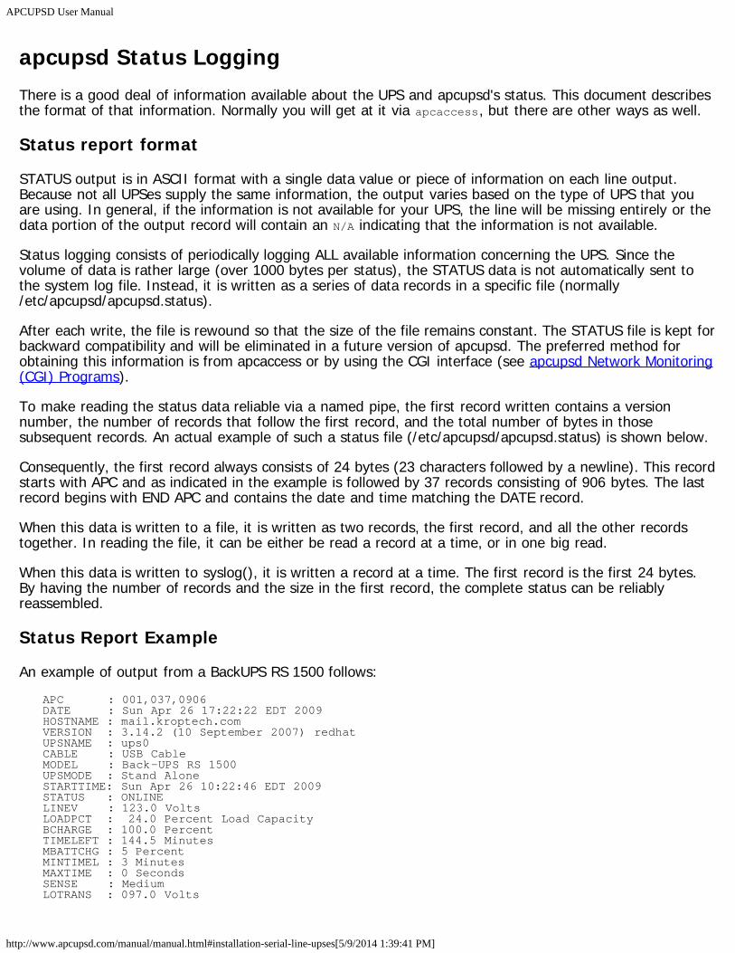
APCUPSD User Manual
http://www.apcupsd.com/manual/manual.html#installation-serial-line-upses[5/9/2014 1:39:41 PM]
apcupsd Status LoggingThere is a good deal of information available about the UPS and apcupsd's status. This document describesthe format of that information. Normally you will get at it via apcaccess, but there are other ways as well.
Status report format
STATUS output is in ASCII format with a single data value or piece of information on each line output.Because not all UPSes supply the same information, the output varies based on the type of UPS that youare using. In general, if the information is not available for your UPS, the line will be missing entirely or thedata portion of the output record will contain an N/A indicating that the information is not available.
Status logging consists of periodically logging ALL available information concerning the UPS. Since thevolume of data is rather large (over 1000 bytes per status), the STATUS data is not automatically sent tothe system log file. Instead, it is written as a series of data records in a specific file (normally/etc/apcupsd/apcupsd.status).
After each write, the file is rewound so that the size of the file remains constant. The STATUS file is kept forbackward compatibility and will be eliminated in a future version of apcupsd. The preferred method forobtaining this information is from apcaccess or by using the CGI interface (see apcupsd Network Monitoring(CGI) Programs).
To make reading the status data reliable via a named pipe, the first record written contains a versionnumber, the number of records that follow the first record, and the total number of bytes in thosesubsequent records. An actual example of such a status file (/etc/apcupsd/apcupsd.status) is shown below.
Consequently, the first record always consists of 24 bytes (23 characters followed by a newline). This recordstarts with APC and as indicated in the example is followed by 37 records consisting of 906 bytes. The lastrecord begins with END APC and contains the date and time matching the DATE record.
When this data is written to a file, it is written as two records, the first record, and all the other recordstogether. In reading the file, it can be either be read a record at a time, or in one big read.
When this data is written to syslog(), it is written a record at a time. The first record is the first 24 bytes.By having the number of records and the size in the first record, the complete status can be reliablyreassembled.
Status Report Example
An example of output from a BackUPS RS 1500 follows:APC : 001,037,0906DATE : Sun Apr 26 17:22:22 EDT 2009HOSTNAME : mail.kroptech.comVERSION : 3.14.2 (10 September 2007) redhatUPSNAME : ups0CABLE : USB CableMODEL : Back-UPS RS 1500UPSMODE : Stand AloneSTARTTIME: Sun Apr 26 10:22:46 EDT 2009STATUS : ONLINELINEV : 123.0 VoltsLOADPCT : 24.0 Percent Load CapacityBCHARGE : 100.0 PercentTIMELEFT : 144.5 MinutesMBATTCHG : 5 PercentMINTIMEL : 3 MinutesMAXTIME : 0 SecondsSENSE : MediumLOTRANS : 097.0 Volts
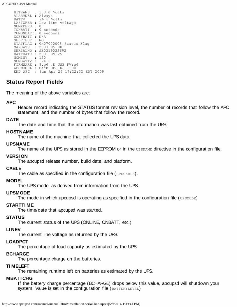
APCUPSD User Manual
http://www.apcupsd.com/manual/manual.html#installation-serial-line-upses[5/9/2014 1:39:41 PM]
HITRANS : 138.0 VoltsALARMDEL : AlwaysBATTV : 26.8 VoltsLASTXFER : Low line voltageNUMXFERS : 0TONBATT : 0 secondsCUMONBATT: 0 secondsXOFFBATT : N/ASELFTEST : NOSTATFLAG : 0x07000008 Status FlagMANDATE : 2003-05-08SERIALNO : JB0319033692BATTDATE : 2001-09-25NOMINV : 120NOMBATTV : 24.0FIRMWARE : 8.g6 .D USB FW:g6APCMODEL : Back-UPS RS 1500END APC : Sun Apr 26 17:22:32 EDT 2009
Status Report Fields
The meaning of the above variables are:
APCHeader record indicating the STATUS format revision level, the number of records that follow the APCstatement, and the number of bytes that follow the record.
DATEThe date and time that the information was last obtained from the UPS.
HOSTNAMEThe name of the machine that collected the UPS data.
UPSNAMEThe name of the UPS as stored in the EEPROM or in the UPSNAME directive in the configuration file.
VERSIONThe apcupsd release number, build date, and platform.
CABLEThe cable as specified in the configuration file (UPSCABLE).
MODELThe UPS model as derived from information from the UPS.
UPSMODEThe mode in which apcupsd is operating as specified in the configuration file (UPSMODE)
STARTTIMEThe time/date that apcupsd was started.
STATUSThe current status of the UPS (ONLINE, ONBATT, etc.)
LINEVThe current line voltage as returned by the UPS.
LOADPCTThe percentage of load capacity as estimated by the UPS.
BCHARGEThe percentage charge on the batteries.
TIMELEFTThe remaining runtime left on batteries as estimated by the UPS.
MBATTCHGIf the battery charge percentage (BCHARGE) drops below this value, apcupsd will shutdown yoursystem. Value is set in the configuration file (BATTERYLEVEL)
APCUPSD User Manual
http://www.apcupsd.com/manual/manual.html#installation-serial-line-upses[5/9/2014 1:39:41 PM]
MINTIMELapcupsd will shutdown your system if the remaining runtime equals or is below this point. Value is setin the configuration file (MINUTES)
MAXTIMEapcupsd will shutdown your system if the time on batteries exceeds this value. A value of zerodisables the feature. Value is set in the configuration file (TIMEOUT)
MAXLINEVThe maximum line voltage since the UPS was started, as reported by the UPS
MINLINEVThe minimum line voltage since the UPS was started, as returned by the UPS
OUTPUTVThe voltage the UPS is supplying to your equipment
SENSEThe sensitivity level of the UPS to line voltage fluctuations.
DWAKEThe amount of time the UPS will wait before restoring power to your equipment after a power offcondition when the power is restored.
DSHUTDThe grace delay that the UPS gives after receiving a power down command from apcupsd before itpowers off your equipment.
DLOWBATTThe remaining runtime below which the UPS sends the low battery signal. At this point apcupsd willforce an immediate emergency shutdown.
LOTRANSThe line voltage below which the UPS will switch to batteries.
HITRANSThe line voltage above which the UPS will switch to batteries.
RETPCTThe percentage charge that the batteries must have after a power off condition before the UPS willrestore power to your equipment.
ITEMPInternal UPS temperature as supplied by the UPS.
ALARMDELThe delay period for the UPS alarm.
BATTVBattery voltage as supplied by the UPS.
LINEFREQLine frequency in hertz as given by the UPS.
LASTXFERThe reason for the last transfer to batteries.
NUMXFERSThe number of transfers to batteries since apcupsd startup.
XONBATTTime and date of last transfer to batteries, or N/A.
TONBATTTime in seconds currently on batteries, or 0.
CUMONBATT
APCUPSD User Manual
http://www.apcupsd.com/manual/manual.html#installation-serial-line-upses[5/9/2014 1:39:41 PM]
Total (cumulative) time on batteries in seconds since apcupsd startup.XOFFBATT
Time and date of last transfer from batteries, or N/A.SELFTEST
The results of the last self test, and may have the following values:
OK: self test indicates good batteryBT: self test failed due to insufficient battery capacityNG: self test failed due to overloadNO: No results (i.e. no self test performed in the last 5 minutes)
STESTIThe interval in hours between automatic self tests.
STATFLAGStatus flag. English version is given by STATUS.
DIPSWThe current dip switch settings on UPSes that have them.
REG1The value from the UPS fault register 1.
REG2The value from the UPS fault register 2.
REG3The value from the UPS fault register 3.
MANDATEThe date the UPS was manufactured.
SERIALNOThe UPS serial number.
BATTDATEThe date that batteries were last replaced.
NOMOUTVThe output voltage that the UPS will attempt to supply when on battery power.
NOMINVThe input voltage that the UPS is configured to expect.
NOMBATTVThe nominal battery voltage.
NOMPOWERThe maximum power in Watts that the UPS is designed to supply.
HUMIDITYThe humidity as measured by the UPS.
AMBTEMPThe ambient temperature as measured by the UPS.
EXTBATTSThe number of external batteries as defined by the user. A correct number here helps the UPScompute the remaining runtime more accurately.
BADBATTSThe number of bad battery packs.
FIRMWAREThe firmware revision number as reported by the UPS.
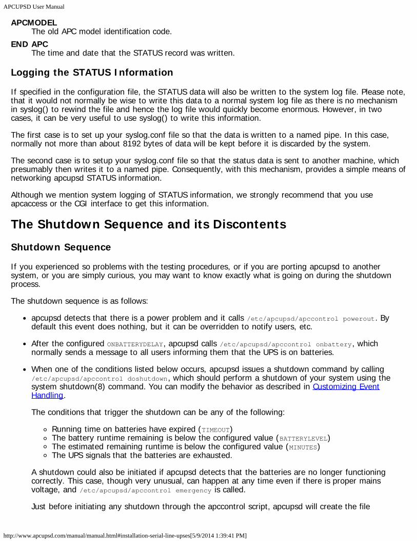
APCUPSD User Manual
http://www.apcupsd.com/manual/manual.html#installation-serial-line-upses[5/9/2014 1:39:41 PM]
APCMODELThe old APC model identification code.
END APCThe time and date that the STATUS record was written.
Logging the STATUS Information
If specified in the configuration file, the STATUS data will also be written to the system log file. Please note,that it would not normally be wise to write this data to a normal system log file as there is no mechanismin syslog() to rewind the file and hence the log file would quickly become enormous. However, in twocases, it can be very useful to use syslog() to write this information.
The first case is to set up your syslog.conf file so that the data is written to a named pipe. In this case,normally not more than about 8192 bytes of data will be kept before it is discarded by the system.
The second case is to setup your syslog.conf file so that the status data is sent to another machine, whichpresumably then writes it to a named pipe. Consequently, with this mechanism, provides a simple means ofnetworking apcupsd STATUS information.
Although we mention system logging of STATUS information, we strongly recommend that you useapcaccess or the CGI interface to get this information.
The Shutdown Sequence and its DiscontentsShutdown Sequence
If you experienced so problems with the testing procedures, or if you are porting apcupsd to anothersystem, or you are simply curious, you may want to know exactly what is going on during the shutdownprocess.
The shutdown sequence is as follows:
apcupsd detects that there is a power problem and it calls /etc/apcupsd/apccontrol powerout. Bydefault this event does nothing, but it can be overridden to notify users, etc.
After the configured ONBATTERYDELAY, apcupsd calls /etc/apcupsd/apccontrol onbattery, whichnormally sends a message to all users informing them that the UPS is on batteries.
When one of the conditions listed below occurs, apcupsd issues a shutdown command by calling/etc/apcupsd/apccontrol doshutdown, which should perform a shutdown of your system using thesystem shutdown(8) command. You can modify the behavior as described in Customizing EventHandling.
The conditions that trigger the shutdown can be any of the following:
Running time on batteries have expired (TIMEOUT)The battery runtime remaining is below the configured value (BATTERYLEVEL)The estimated remaining runtime is below the configured value (MINUTES)The UPS signals that the batteries are exhausted.
A shutdown could also be initiated if apcupsd detects that the batteries are no longer functioningcorrectly. This case, though very unusual, can happen at any time even if there is proper mainsvoltage, and /etc/apcupsd/apccontrol emergency is called.
Just before initiating any shutdown through the apccontrol script, apcupsd will create the file
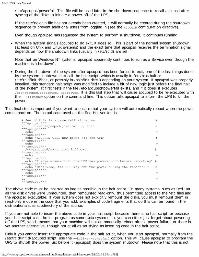
APCUPSD User Manual
http://www.apcupsd.com/manual/manual.html#installation-serial-line-upses[5/9/2014 1:39:41 PM]
/etc/apcupsd/powerfail. This file will be used later in the shutdown sequence to recall apcupsd aftersyncing of the disks to initiate a power off of the UPS.
If the /etc/nologin file has not already been created, it will normally be created during the shutdownsequence to prevent additional users from logging in (see the NOLOGIN configuration directive).
Even though apcupsd has requested the system to perform a shutdown, it continues running.
When the system signals apcupsd to do exit, it does so. This is part of the normal system shutdown(at least on Unix and Linux systems) and the exact time that apcupsd receives the termination signaldepends on how the shutdown links (usually in /etc/rc.d) are set.
Note that on Windows NT systems, apcupsd apparently continues to run as a Service even though themachine is "shutdown".
During the shutdown of the system after apcupsd has been forced to exit, one of the last things doneby the system shutdown is to call the halt script, which is usually in /etc/rc.d/halt or/etc/rc.d/init.d/halt, or possibly in /sbin/init.d/rc.0 depending on your system. If apcupsd was properlyinstalled, this standard halt script was modified to include a bit of new logic just before the final haltof the system. It first tests if the file /etc/apcupsd/powerfail exists, and if it does, it executes/etc/apcupsd/apccontrol killpower. It is this last step that will cause apcupsd to be re-executed withthe --killpower option on the command line. This option tells apcupsd to inform the UPS to kill thepower.
This final step is important if you want to ensure that your system will automatically reboot when the powercomes back on. The actual code used on the Red Hat version is:
# See if this is a powerfail situation. # ***apcupsd***if [ -f /etc/apcupsd/powerfail ]; then # ***apcupsd*** echo # ***apcupsd*** echo "APCUPSD will now power off the UPS" # ***apcupsd*** echo # ***apcupsd*** /etc/apcupsd/apccontrol killpower # ***apcupsd*** echo # ***apcupsd*** echo "Please ensure that the UPS has powered off before rebooting" # ***apcupsd*** echo "Otherwise, the UPS may cut the power during the reboot!!!" # ***apcupsd*** echo # ***apcupsd***fi # ***apcupsd***
The above code must be inserted as late as possible in the halt script. On many systems, such as Red Hat,all the disk drives were unmounted, then remounted read-only, thus permitting access to the /etc files andthe apcupsd executable. If your system does not explicitly remount the disks, you must remount them inread-only mode in the code that you add. Examples of code fragments that do this can be found in thedistributions/suse subdirectory of the source.
If you are not able to insert the above code in your halt script because there is no halt script, or becauseyour halt script calls the init program as some Unix systems do, you can either just forget about poweringoff the UPS, which means that your machine will not automatically reboot after a power failure, or there isyet another alternative, though not at all as satisfying as inserting code in the halt script.
Only if you cannot insert the appropriate code in the halt script, when you start apcupsd, normally from the/etc/rc.d/init.d/apcupsd script, use the --kill-on-powerfail option. This will cause apcupsd to program theUPS to shutoff the power just before it (apcupsd) does the system shutdown. Please note that this is not
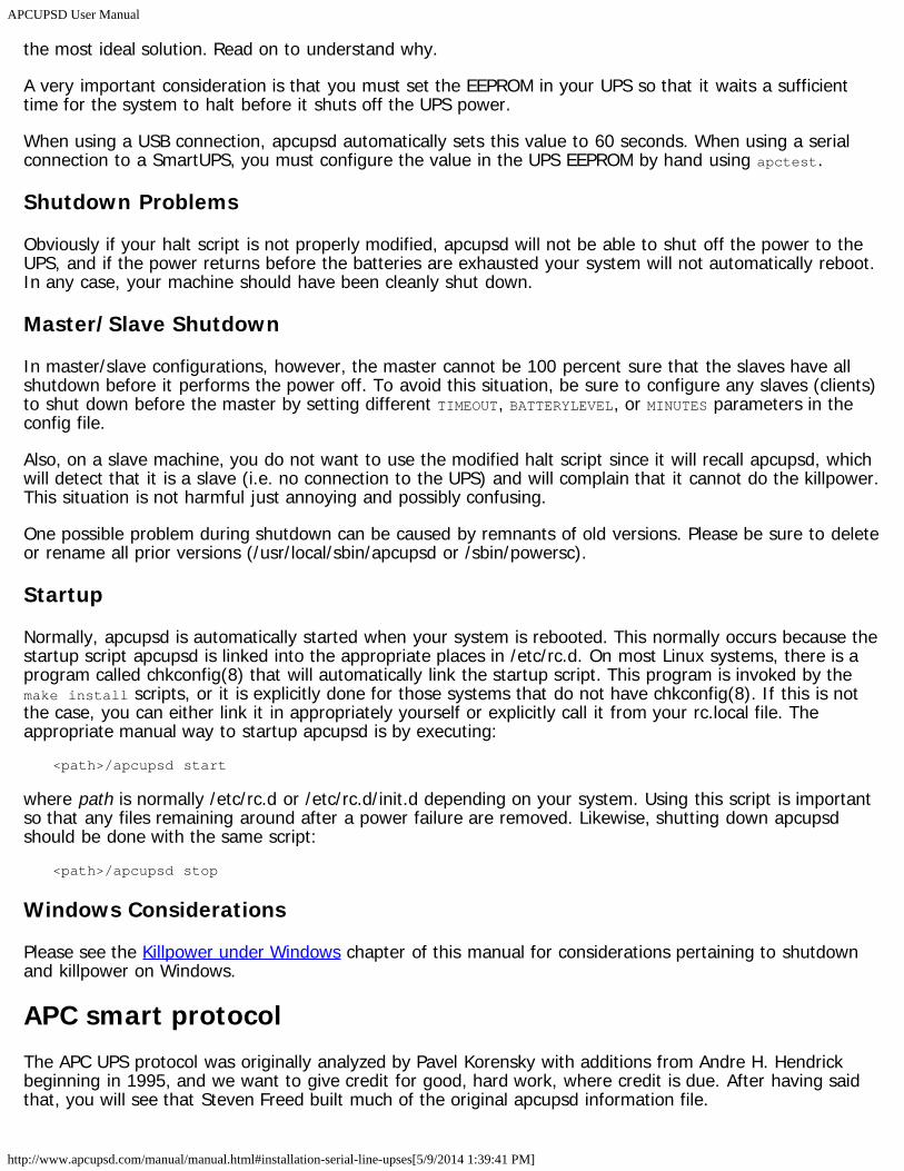
APCUPSD User Manual
http://www.apcupsd.com/manual/manual.html#installation-serial-line-upses[5/9/2014 1:39:41 PM]
the most ideal solution. Read on to understand why.
A very important consideration is that you must set the EEPROM in your UPS so that it waits a sufficienttime for the system to halt before it shuts off the UPS power.
When using a USB connection, apcupsd automatically sets this value to 60 seconds. When using a serialconnection to a SmartUPS, you must configure the value in the UPS EEPROM by hand using apctest.
Shutdown Problems
Obviously if your halt script is not properly modified, apcupsd will not be able to shut off the power to theUPS, and if the power returns before the batteries are exhausted your system will not automatically reboot.In any case, your machine should have been cleanly shut down.
Master/Slave Shutdown
In master/slave configurations, however, the master cannot be 100 percent sure that the slaves have allshutdown before it performs the power off. To avoid this situation, be sure to configure any slaves (clients)to shut down before the master by setting different TIMEOUT, BATTERYLEVEL, or MINUTES parameters in theconfig file.
Also, on a slave machine, you do not want to use the modified halt script since it will recall apcupsd, whichwill detect that it is a slave (i.e. no connection to the UPS) and will complain that it cannot do the killpower.This situation is not harmful just annoying and possibly confusing.
One possible problem during shutdown can be caused by remnants of old versions. Please be sure to deleteor rename all prior versions (/usr/local/sbin/apcupsd or /sbin/powersc).
Startup
Normally, apcupsd is automatically started when your system is rebooted. This normally occurs because thestartup script apcupsd is linked into the appropriate places in /etc/rc.d. On most Linux systems, there is aprogram called chkconfig(8) that will automatically link the startup script. This program is invoked by themake install scripts, or it is explicitly done for those systems that do not have chkconfig(8). If this is notthe case, you can either link it in appropriately yourself or explicitly call it from your rc.local file. Theappropriate manual way to startup apcupsd is by executing:
<path>/apcupsd start
where path is normally /etc/rc.d or /etc/rc.d/init.d depending on your system. Using this script is importantso that any files remaining around after a power failure are removed. Likewise, shutting down apcupsdshould be done with the same script:
<path>/apcupsd stop
Windows Considerations
Please see the Killpower under Windows chapter of this manual for considerations pertaining to shutdownand killpower on Windows.
APC smart protocolThe APC UPS protocol was originally analyzed by Pavel Korensky with additions from Andre H. Hendrickbeginning in 1995, and we want to give credit for good, hard work, where credit is due. After having saidthat, you will see that Steven Freed built much of the original apcupsd information file.
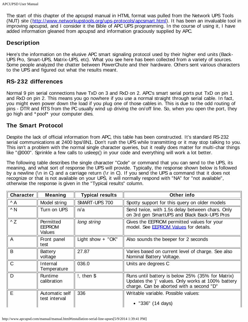
APCUPSD User Manual
http://www.apcupsd.com/manual/manual.html#installation-serial-line-upses[5/9/2014 1:39:41 PM]
The start of this chapter of the apcupsd manual in HTML format was pulled from the Network UPS Tools(NUT) site (http://www.networkupstools.org/ups-protocols/apcsmart.html). It has been an invaluable tool inimproving apcupsd, and I consider it the Bible of APC UPS programming. In the course of using it, I haveadded information gleaned from apcupsd and information graciously supplied by APC.
Description
Here's the information on the elusive APC smart signaling protocol used by their higher end units (Back-UPS Pro, Smart-UPS, Matrix-UPS, etc). What you see here has been collected from a variety of sources.Some people analyzed the chatter between PowerChute and their hardware. Others sent various charactersto the UPS and figured out what the results meant.
RS-232 differences
Normal 9 pin serial connections have TxD on 3 and RxD on 2. APC's smart serial ports put TxD on pin 1and RxD on pin 2. This means you go nowhere if you use a normal straight through serial cable. In fact,you might even power down the load if you plug one of those cables in. This is due to the odd routing ofpins - DTR and RTS from the PC usually wind up driving the on/off line. So, when you open the port, theygo high and *poof* your computer dies.
The Smart Protocol
Despite the lack of official information from APC, this table has been constructed. It's standard RS-232serial communications at 2400 bps/8N1. Don't rush the UPS while transmitting or it may stop talking to you.This isn't a problem with the normal single character queries, but it really does matter for multi-char thingslike "@000". Sprinkle a few calls to usleep() in your code and everything will work a lot better.
The following table describes the single character "Code" or command that you can send to the UPS, itsmeaning, and what sort of response the UPS will provide. Typically, the response shown below is followedby a newline (\n in C) and a carriage return (\r in C). If you send the UPS a command that it does notrecognize or that is not available on your UPS, it will normally respond with "NA" for "not available",otherwise the response is given in the "Typical results" column.
Character Meaning Typical results Other info^A Model string SMART-UPS 700 Spotty support for this query on older models^N Turn on UPS n/a Send twice, with 1.5s delay between chars. Only
on 3rd gen SmartUPS and Black Back-UPS Pros^Z Permitted
EEPROMValues
long string Gives the EEPROM permitted values for yourmodel. See EEPROM Values for details.
A Front paneltest
Light show + "OK" Also sounds the beeper for 2 seconds
B Batteryvoltage
27.87 Varies based on current level of charge. See alsoNominal Battery Voltage.
C InternalTemperature
036.0 Units are degrees C
D Runtimecalibration
!, then $ Runs until battery is below 25% (35% for Matrix)Updates the 'j' values. Only works at 100% batterycharge. Can be aborted with a second "D"
E Automatic selftest interval
336 Writable variable. Possible values:
"336" (14 days)
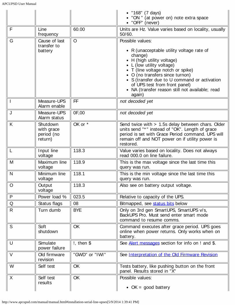
APCUPSD User Manual
http://www.apcupsd.com/manual/manual.html#installation-serial-line-upses[5/9/2014 1:39:41 PM]
"168" (7 days)"ON " (at power on) note extra space"OFF" (never)
F Linefrequency
60.00 Units are Hz. Value varies based on locality, usually50/60.
G Cause of lasttransfer tobattery
O Possible values:
R (unacceptable utility voltage rate ofchange)H (high utility voltage)L (low utility voltage)T (line voltage notch or spike)O (no transfers since turnon)S (transfer due to U command or activationof UPS test from front panel)NA (transfer reason still not available; readagain)
I Measure-UPSAlarm enable
FF not decoded yet
J Measure-UPSAlarm status
0F,00 not decoded yet
K Shutdownwith graceperiod (noreturn)
OK or * Send twice with > 1.5s delay between chars. Olderunits send "*" instead of "OK". Length of graceperiod is set with Grace Period command. UPS willremain off and NOT power on if utility power isrestored.
L Input linevoltage
118.3 Value varies based on locality. Does not alwaysread 000.0 on line failure.
M Maximum linevoltage
118.9 This is the max voltage since the last time thisquery was run.
N Minimum linevoltage
118.1 This is the min voltage since the last time thisquery was run.
O Outputvoltage
118.3 Also see on battery output voltage.
P Power load % 023.5 Relative to capacity of the UPS.Q Status flags 08 Bitmapped, see status bits belowR Turn dumb BYE Only on 3rd gen SmartUPS, SmartUPS v/s,
BackUPS Pro. Must send enter smart modecommand to resume comms.
S Softshutdown
OK Command executes after grace period. UPS goesonline when power returns. Only works when onbattery.
U Simulatepower failure
!, then $ See Alert messages section for info on ! and $.
V Old firmwarerevision
"GWD" or "IWI" See Interpretation of the Old Firmware Revision
W Self test OK Tests battery, like pushing button on the frontpanel. Results stored in "X"
X Self testresults
OK Possible values:
OK = good battery
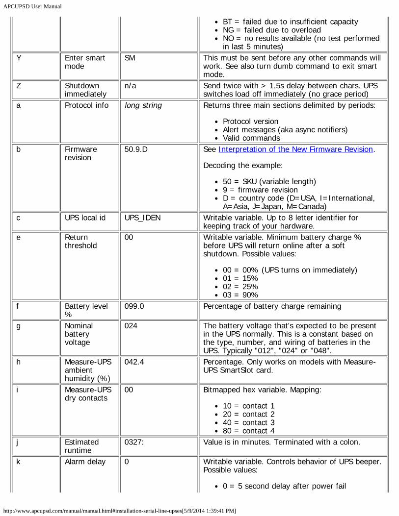
APCUPSD User Manual
http://www.apcupsd.com/manual/manual.html#installation-serial-line-upses[5/9/2014 1:39:41 PM]
BT = failed due to insufficient capacityNG = failed due to overloadNO = no results available (no test performedin last 5 minutes)
Y Enter smartmode
SM This must be sent before any other commands willwork. See also turn dumb command to exit smartmode.
Z Shutdownimmediately
n/a Send twice with > 1.5s delay between chars. UPSswitches load off immediately (no grace period)
a Protocol info long string Returns three main sections delimited by periods:
Protocol versionAlert messages (aka async notifiers)Valid commands
b Firmwarerevision
50.9.D See Interpretation of the New Firmware Revision.
Decoding the example:
50 = SKU (variable length)9 = firmware revisionD = country code (D=USA, I=International,A=Asia, J=Japan, M=Canada)
c UPS local id UPS_IDEN Writable variable. Up to 8 letter identifier forkeeping track of your hardware.
e Returnthreshold
00 Writable variable. Minimum battery charge %before UPS will return online after a softshutdown. Possible values:
00 = 00% (UPS turns on immediately)01 = 15%02 = 25%03 = 90%
f Battery level%
099.0 Percentage of battery charge remaining
g Nominalbatteryvoltage
024 The battery voltage that's expected to be presentin the UPS normally. This is a constant based onthe type, number, and wiring of batteries in theUPS. Typically "012", "024" or "048".
h Measure-UPSambienthumidity (%)
042.4 Percentage. Only works on models with Measure-UPS SmartSlot card.
i Measure-UPSdry contacts
00 Bitmapped hex variable. Mapping:
10 = contact 120 = contact 240 = contact 380 = contact 4
j Estimatedruntime
0327: Value is in minutes. Terminated with a colon.
k Alarm delay 0 Writable variable. Controls behavior of UPS beeper.Possible values:
0 = 5 second delay after power fail
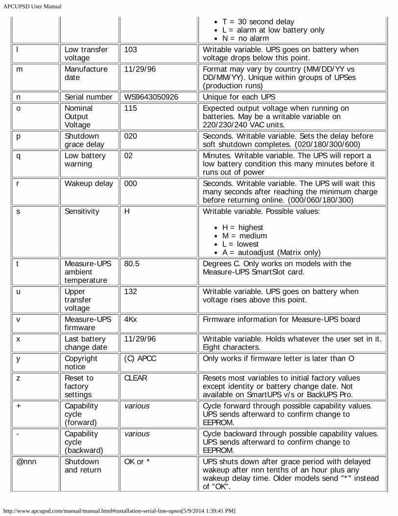
APCUPSD User Manual
http://www.apcupsd.com/manual/manual.html#installation-serial-line-upses[5/9/2014 1:39:41 PM]
T = 30 second delayL = alarm at low battery onlyN = no alarm
l Low transfervoltage
103 Writable variable. UPS goes on battery whenvoltage drops below this point.
m Manufacturedate
11/29/96 Format may vary by country (MM/DD/YY vsDD/MM/YY). Unique within groups of UPSes(production runs)
n Serial number WS9643050926 Unique for each UPSo Nominal
OutputVoltage
115 Expected output voltage when running onbatteries. May be a writable variable on220/230/240 VAC units.
p Shutdowngrace delay
020 Seconds. Writable variable. Sets the delay beforesoft shutdown completes. (020/180/300/600)
q Low batterywarning
02 Minutes. Writable variable. The UPS will report alow battery condition this many minutes before itruns out of power
r Wakeup delay 000 Seconds. Writable variable. The UPS will wait thismany seconds after reaching the minimum chargebefore returning online. (000/060/180/300)
s Sensitivity H Writable variable. Possible values:
H = highestM = mediumL = lowestA = autoadjust (Matrix only)
t Measure-UPSambienttemperature
80.5 Degrees C. Only works on models with theMeasure-UPS SmartSlot card.
u Uppertransfervoltage
132 Writable variable. UPS goes on battery whenvoltage rises above this point.
v Measure-UPSfirmware
4Kx Firmware information for Measure-UPS board
x Last batterychange date
11/29/96 Writable variable. Holds whatever the user set in it.Eight characters.
y Copyrightnotice
(C) APCC Only works if firmware letter is later than O
z Reset tofactorysettings
CLEAR Resets most variables to initial factory valuesexcept identity or battery change date. Notavailable on SmartUPS v/s or BackUPS Pro.
+ Capabilitycycle(forward)
various Cycle forward through possible capability values.UPS sends afterward to confirm change toEEPROM.
- Capabilitycycle(backward)
various Cycle backward through possible capability values.UPS sends afterward to confirm change toEEPROM.
@nnn Shutdownand return
OK or * UPS shuts down after grace period with delayedwakeup after nnn tenths of an hour plus anywakeup delay time. Older models send "*" insteadof "OK".
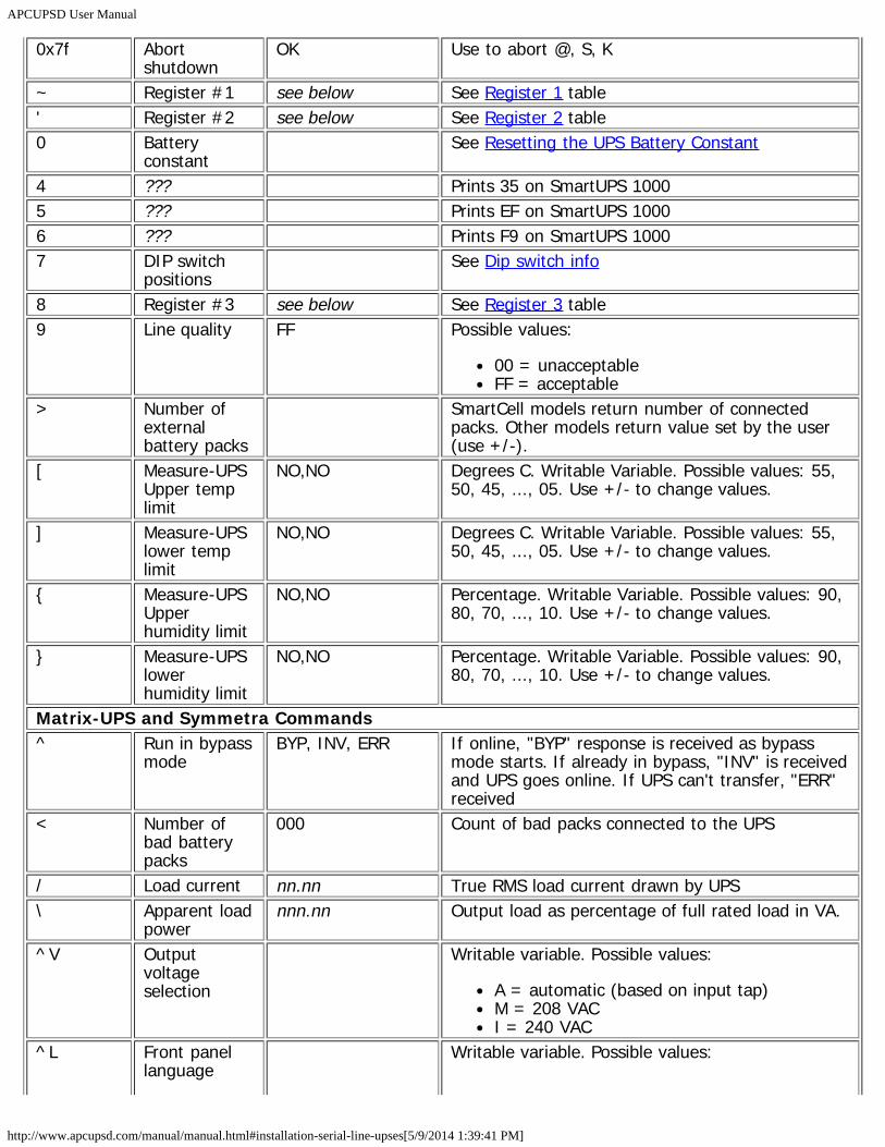
APCUPSD User Manual
http://www.apcupsd.com/manual/manual.html#installation-serial-line-upses[5/9/2014 1:39:41 PM]
0x7f Abortshutdown
OK Use to abort @, S, K
~ Register #1 see below See Register 1 table' Register #2 see below See Register 2 table0 Battery
constant See Resetting the UPS Battery Constant
4 ??? Prints 35 on SmartUPS 10005 ??? Prints EF on SmartUPS 10006 ??? Prints F9 on SmartUPS 10007 DIP switch
positions See Dip switch info
8 Register #3 see below See Register 3 table9 Line quality FF Possible values:
00 = unacceptableFF = acceptable
> Number ofexternalbattery packs
SmartCell models return number of connectedpacks. Other models return value set by the user(use +/-).
[ Measure-UPSUpper templimit
NO,NO Degrees C. Writable Variable. Possible values: 55,50, 45, ..., 05. Use +/- to change values.
] Measure-UPSlower templimit
NO,NO Degrees C. Writable Variable. Possible values: 55,50, 45, ..., 05. Use +/- to change values.
{ Measure-UPSUpperhumidity limit
NO,NO Percentage. Writable Variable. Possible values: 90,80, 70, ..., 10. Use +/- to change values.
} Measure-UPSlowerhumidity limit
NO,NO Percentage. Writable Variable. Possible values: 90,80, 70, ..., 10. Use +/- to change values.
Matrix-UPS and Symmetra Commands^ Run in bypass
modeBYP, INV, ERR If online, "BYP" response is received as bypass
mode starts. If already in bypass, "INV" is receivedand UPS goes online. If UPS can't transfer, "ERR"received
< Number ofbad batterypacks
000 Count of bad packs connected to the UPS
/ Load current nn.nn True RMS load current drawn by UPS\ Apparent load
powernnn.nn Output load as percentage of full rated load in VA.
^V Outputvoltageselection
Writable variable. Possible values:
A = automatic (based on input tap)M = 208 VACI = 240 VAC
^L Front panellanguage
Writable variable. Possible values:
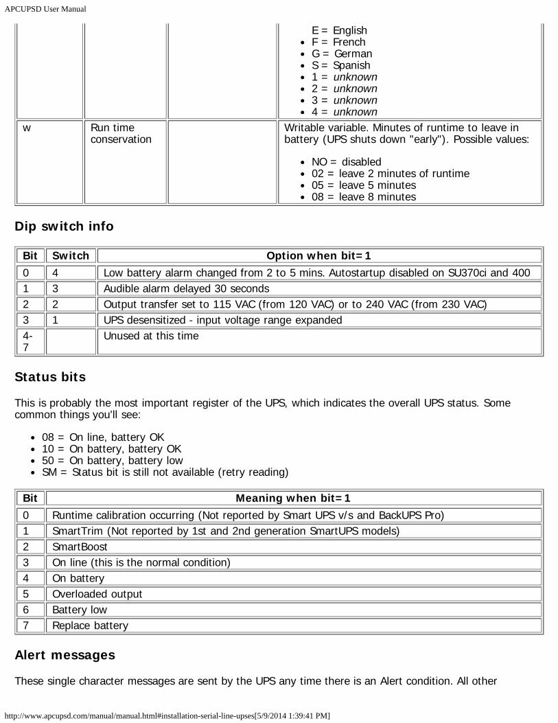
APCUPSD User Manual
http://www.apcupsd.com/manual/manual.html#installation-serial-line-upses[5/9/2014 1:39:41 PM]
E = EnglishF = FrenchG = GermanS = Spanish1 = unknown2 = unknown3 = unknown4 = unknown
w Run timeconservation
Writable variable. Minutes of runtime to leave inbattery (UPS shuts down "early"). Possible values:
NO = disabled02 = leave 2 minutes of runtime05 = leave 5 minutes08 = leave 8 minutes
Dip switch info
Bit Switch Option when bit=10 4 Low battery alarm changed from 2 to 5 mins. Autostartup disabled on SU370ci and 4001 3 Audible alarm delayed 30 seconds2 2 Output transfer set to 115 VAC (from 120 VAC) or to 240 VAC (from 230 VAC)3 1 UPS desensitized - input voltage range expanded4-7
Unused at this time
Status bits
This is probably the most important register of the UPS, which indicates the overall UPS status. Somecommon things you'll see:
08 = On line, battery OK10 = On battery, battery OK50 = On battery, battery lowSM = Status bit is still not available (retry reading)
Bit Meaning when bit=10 Runtime calibration occurring (Not reported by Smart UPS v/s and BackUPS Pro)1 SmartTrim (Not reported by 1st and 2nd generation SmartUPS models)2 SmartBoost3 On line (this is the normal condition)4 On battery5 Overloaded output6 Battery low7 Replace battery
Alert messages
These single character messages are sent by the UPS any time there is an Alert condition. All other
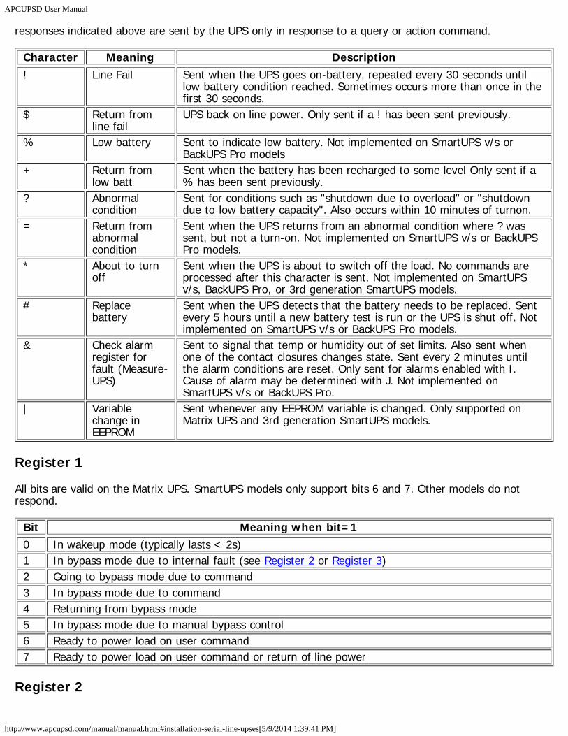
APCUPSD User Manual
http://www.apcupsd.com/manual/manual.html#installation-serial-line-upses[5/9/2014 1:39:41 PM]
responses indicated above are sent by the UPS only in response to a query or action command.
Character Meaning Description! Line Fail Sent when the UPS goes on-battery, repeated every 30 seconds until
low battery condition reached. Sometimes occurs more than once in thefirst 30 seconds.
$ Return fromline fail
UPS back on line power. Only sent if a ! has been sent previously.
% Low battery Sent to indicate low battery. Not implemented on SmartUPS v/s orBackUPS Pro models
+ Return fromlow batt
Sent when the battery has been recharged to some level Only sent if a% has been sent previously.
? Abnormalcondition
Sent for conditions such as "shutdown due to overload" or "shutdowndue to low battery capacity". Also occurs within 10 minutes of turnon.
= Return fromabnormalcondition
Sent when the UPS returns from an abnormal condition where ? wassent, but not a turn-on. Not implemented on SmartUPS v/s or BackUPSPro models.
* About to turnoff
Sent when the UPS is about to switch off the load. No commands areprocessed after this character is sent. Not implemented on SmartUPSv/s, BackUPS Pro, or 3rd generation SmartUPS models.
# Replacebattery
Sent when the UPS detects that the battery needs to be replaced. Sentevery 5 hours until a new battery test is run or the UPS is shut off. Notimplemented on SmartUPS v/s or BackUPS Pro models.
& Check alarmregister forfault (Measure-UPS)
Sent to signal that temp or humidity out of set limits. Also sent whenone of the contact closures changes state. Sent every 2 minutes untilthe alarm conditions are reset. Only sent for alarms enabled with I.Cause of alarm may be determined with J. Not implemented onSmartUPS v/s or BackUPS Pro.
| Variablechange inEEPROM
Sent whenever any EEPROM variable is changed. Only supported onMatrix UPS and 3rd generation SmartUPS models.
Register 1
All bits are valid on the Matrix UPS. SmartUPS models only support bits 6 and 7. Other models do notrespond.
Bit Meaning when bit=10 In wakeup mode (typically lasts < 2s)1 In bypass mode due to internal fault (see Register 2 or Register 3)2 Going to bypass mode due to command3 In bypass mode due to command4 Returning from bypass mode5 In bypass mode due to manual bypass control6 Ready to power load on user command7 Ready to power load on user command or return of line power
Register 2
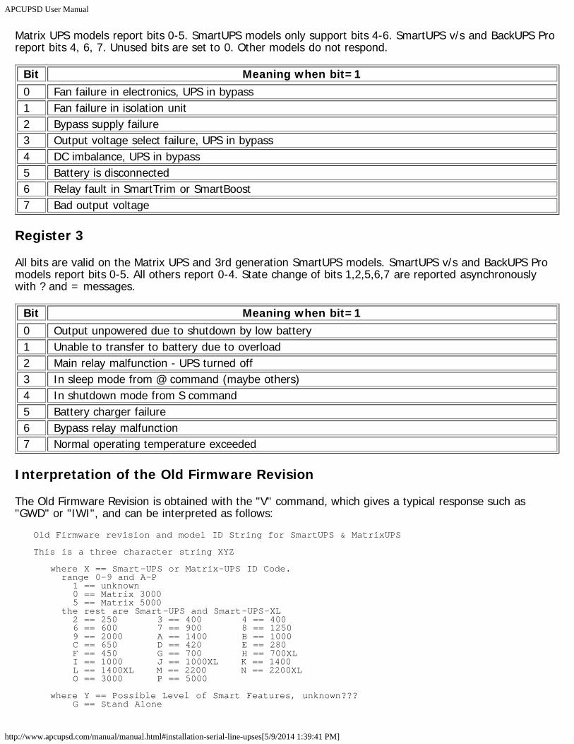
APCUPSD User Manual
http://www.apcupsd.com/manual/manual.html#installation-serial-line-upses[5/9/2014 1:39:41 PM]
Matrix UPS models report bits 0-5. SmartUPS models only support bits 4-6. SmartUPS v/s and BackUPS Proreport bits 4, 6, 7. Unused bits are set to 0. Other models do not respond.
Bit Meaning when bit=10 Fan failure in electronics, UPS in bypass1 Fan failure in isolation unit2 Bypass supply failure3 Output voltage select failure, UPS in bypass4 DC imbalance, UPS in bypass5 Battery is disconnected6 Relay fault in SmartTrim or SmartBoost7 Bad output voltage
Register 3
All bits are valid on the Matrix UPS and 3rd generation SmartUPS models. SmartUPS v/s and BackUPS Promodels report bits 0-5. All others report 0-4. State change of bits 1,2,5,6,7 are reported asynchronouslywith ? and = messages.
Bit Meaning when bit=10 Output unpowered due to shutdown by low battery1 Unable to transfer to battery due to overload2 Main relay malfunction - UPS turned off3 In sleep mode from @ command (maybe others)4 In shutdown mode from S command5 Battery charger failure6 Bypass relay malfunction7 Normal operating temperature exceeded
Interpretation of the Old Firmware Revision
The Old Firmware Revision is obtained with the "V" command, which gives a typical response such as"GWD" or "IWI", and can be interpreted as follows:
Old Firmware revision and model ID String for SmartUPS & MatrixUPS
This is a three character string XYZ
where X == Smart-UPS or Matrix-UPS ID Code. range 0-9 and A-P 1 == unknown 0 == Matrix 3000 5 == Matrix 5000 the rest are Smart-UPS and Smart-UPS-XL 2 == 250 3 == 400 4 == 400 6 == 600 7 == 900 8 == 1250 9 == 2000 A == 1400 B == 1000 C == 650 D == 420 E == 280 F == 450 G == 700 H == 700XL I == 1000 J == 1000XL K == 1400 L == 1400XL M == 2200 N == 2200XL O == 3000 P == 5000
where Y == Possible Level of Smart Features, unknown??? G == Stand Alone
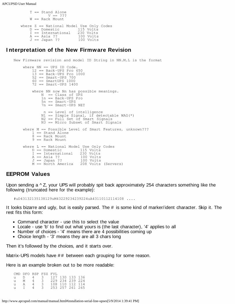
APCUPSD User Manual
http://www.apcupsd.com/manual/manual.html#installation-serial-line-upses[5/9/2014 1:39:41 PM]
T == Stand Alone V == ??? W == Rack Mount
where Z == National Model Use Only Codes D == Domestic 115 Volts I == International 230 Volts A == Asia ?? 100 Volts J == Japan ?? 100 Volts
Interpretation of the New Firmware RevisionNew Firmware revision and model ID String in NN.M.L is the format
where NN == UPS ID Code. 12 == Back-UPS Pro 650 13 == Back-UPS Pro 1000 52 == Smart-UPS 700 60 == SmartUPS 1000 72 == Smart-UPS 1400
where NN now Nn has possible meanings. N == Class of UPS 1n == Back-UPS Pro 5n == Smart-UPS 7n == Smart-UPS NET
n == Level of intelligence N1 == Simple Signal, if detectable WAG(*) N2 == Full Set of Smart Signals N3 == Micro Subset of Smart Signals
where M == Possible Level of Smart Features, unknown??? 1 == Stand Alone 8 == Rack Mount 9 == Rack Mount
where L == National Model Use Only Codes D == Domestic 115 Volts I == International 230 Volts A == Asia ?? 100 Volts J == Japan ?? 100 Volts M == North America 208 Volts (Servers)
EEPROM Values
Upon sending a ^Z, your UPS will probably spit back approximately 254 characters something like thefollowing (truncated here for the example):
#uD43132135138129uM43229234239224uA43110112114108 ....
It looks bizarre and ugly, but is easily parsed. The # is some kind of marker/ident character. Skip it. Therest fits this form:
Command character - use this to select the valueLocale - use 'b' to find out what yours is (the last character), '4' applies to allNumber of choices - '4' means there are 4 possibilities coming upChoice length - '3' means they are all 3 chars long
Then it's followed by the choices, and it starts over.
Matrix-UPS models have ## between each grouping for some reason.
Here is an example broken out to be more readable:CMD DFO RSP FSZ FVLu D 4 3 127 130 133 136u M 4 3 229 234 239 224u A 4 3 108 110 112 114u I 4 3 253 257 261 265
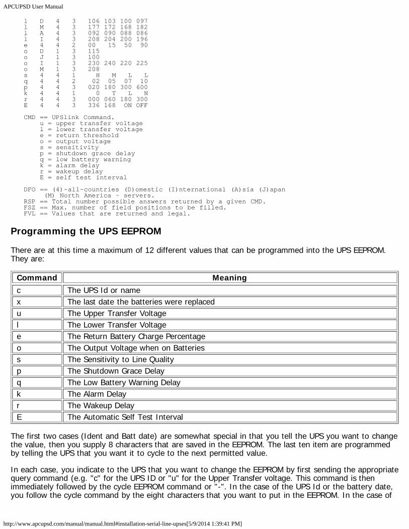
APCUPSD User Manual
http://www.apcupsd.com/manual/manual.html#installation-serial-line-upses[5/9/2014 1:39:41 PM]
l D 4 3 106 103 100 097l M 4 3 177 172 168 182l A 4 3 092 090 088 086l I 4 3 208 204 200 196e 4 4 2 00 15 50 90o D 1 3 115o J 1 3 100o I 1 3 230 240 220 225o M 1 3 208s 4 4 1 H M L Lq 4 4 2 02 05 07 10p 4 4 3 020 180 300 600k 4 4 1 0 T L Nr 4 4 3 000 060 180 300E 4 4 3 336 168 ON OFF
CMD == UPSlink Command. u = upper transfer voltage l = lower transfer voltage e = return threshold o = output voltage s = sensitivity p = shutdown grace delay q = low battery warning k = alarm delay r = wakeup delay E = self test interval
DFO == (4)-all-countries (D)omestic (I)nternational (A)sia (J)apan (M) North America - servers.RSP == Total number possible answers returned by a given CMD.FSZ == Max. number of field positions to be filled.FVL == Values that are returned and legal.
Programming the UPS EEPROM
There are at this time a maximum of 12 different values that can be programmed into the UPS EEPROM.They are:
Command Meaningc The UPS Id or namex The last date the batteries were replacedu The Upper Transfer Voltagel The Lower Transfer Voltagee The Return Battery Charge Percentageo The Output Voltage when on Batteriess The Sensitivity to Line Qualityp The Shutdown Grace Delayq The Low Battery Warning Delayk The Alarm Delayr The Wakeup DelayE The Automatic Self Test Interval
The first two cases (Ident and Batt date) are somewhat special in that you tell the UPS you want to changethe value, then you supply 8 characters that are saved in the EEPROM. The last ten item are programmedby telling the UPS that you want it to cycle to the next permitted value.
In each case, you indicate to the UPS that you want to change the EEPROM by first sending the appropriatequery command (e.g. "c" for the UPS ID or "u" for the Upper Transfer voltage. This command is thenimmediately followed by the cycle EEPROM command or "-". In the case of the UPS Id or the battery date,you follow the cycle command by the eight characters that you want to put in the EEPROM. In the case of
APCUPSD User Manual
http://www.apcupsd.com/manual/manual.html#installation-serial-line-upses[5/9/2014 1:39:41 PM]
the other ten items, there is nothing more to enter.
The UPS will respond by "OK" and approximately 5 seconds later by a vertical bar (|) to indicate that theEEPROM was changed.
NIS Network Server ProtocolThe NIS network server in apcupsd is capable of sending status and events data to clients that request it.The communication between the client and the server is performed over a TCP connection to the NISPORT(normally port 3551). The client opens a connection to the server and sends a message, to which theserver will reply with one or more messages. Each message consists of a 2-byte length (in network byteorder) followed by that many bytes of data. Both the client->server and server->client messages follow thisformat.
apcupsd supports two commands, sent as the body of a message:
1. "status" - The status command requests that the server send a copy of all status values, in the formdisplayed by apcaccess. After the client sends the "status" command, the server will reply with aseries of messges, each one containing one line of apcaccess status data. The end of the commandseries is indicated by an empty message (length of 0).
2. "events" - The events command operates the same as "status" except the server replies with linesfrom the log of recent events.
As an example, the following bytes would be sent by a client to solicit the status:0x00 0x06 0x73 0x74 0x61 0x74 0x75 0x73
The first two bytes are the data length (6) in network byte order. The 6 bytes of data that follow are theASCII characters for "status". The server will respond to this command with a series of its own messagescontaining the status data.
Apcupsd RPM Packaging FAQHow do I build Apcupsd for platform xxx?
The apcupsd spec file contains defines to build for several platforms: RedHat 7.x (rh7), RedHat 8.0(rh8), RedHat 9 (rh9), Fedora Core (fedora_core), RedHat Enterprise Linux and clones (rhel3 andrhel4), SuSE 9 & 10 (suse), and Mandrake (mdk). The package build is controlled by a define set atthe beginning of the file. These defines basically just control the dependency information that getscoded into the finished rpm package. So while you could technically build a package without defininga platform, or with an incorrect platform, and have it install and run it would not contain correctdependency information for the rpm database. The platform define may be edited in the spec filedirectly (by default all defines are set to 0 or "not set"). For example, to build the RedHat 7.x packagefind the line in the spec file which reads
%define rh7 0
and edit it to read%define rh7 1
Alternately you may pass the define on the command line when calling rpmbuild:rpmbuild -ba --define "build_rh7 1" apcupsd.specrpmbuild --rebuild --define build_rh7 1" apcupsd-x.x.x-x.src.rpm
How do I control whether usb support gets built?Up through version 3.12, by default standard serial port support was built and the apcupsd-stdpackage was produced. The usb package pre-configured the configuration files for usb devices and
APCUPSD User Manual
http://www.apcupsd.com/manual/manual.html#installation-serial-line-upses[5/9/2014 1:39:41 PM]
installed a couple additional tools in /etc/apcupsd but the usb driver was built regardless. To get theusb package and support in those versions either set the
%define usb 0
to%define usb 1
in the spec file directly or pass it to rpmbuild on the command line:rpmbuild -ba --define "build_rh7 1" --define "build_usb 1" apcupsd.spec
With the release of 3.14 USB support is now considered standard and the apcupsd-std and apcupsd-usb packages are obsoleted in favor of a single apcupsd package configured for usb connected UPS's.The serial port driver is still built and can be configured accordingly after installation. If you areperforming an upgrade it will of course not replace your current config file.
The build directive:--define "build_usb 1"
is no longer recognized.What other defines are used?
There is a define for the initdir for the daemon control script. On RedHat or Mandrake systems this isset to /etc/rc.d/init.d/. On SuSE systems this is set to /etc/rc.d. You would only need to edit this ifpackaging for a platform that uses a different directory.
A second define controls whether the Gnome monitoring application, new in the 3.14 release, is built.This application requires the Gtk2 version to be >= 2.4. If you want to build the apcupsd-gapcmonpackage add:
--define "build_gapcmon 1"
A third define controls whether the SNMP driver is built. If you want to build the net-snmp driver add:--define "build_snmp 1"
Can I supply packages for other platforms you do not publish?Yes, there are tools provided for contributors to supply rpm packages for platforms for which supportis provided in the spec file but for which the development team chooses not to release binarypackages, usually due to lack of interest or lack of an available platform. Please seeplatforms/contrib/README in the source package.
I'm getting errors about not having permission when I try to build the packages. Do I need tobe root?
No, you do not need to be root and, in fact, it is better practice to build rpm packages as a non-rootuser. Apcupsd's packages are designed to be built by a regular user but you must make a fewchanges on your system to do this. If you are building on your own system then the simplest methodis to add write permissions for all to the build directory (/usr/src/redhat/). To accomplish this executeone of the following commands as root depending on your distribution, RedHat, SuSE or Mandriva,respectively:
chmod -R 777 /usr/src/redhatchmod -R 777 /usr/src/packageschmod -R 777 /usr/src/RPM
If you are working on a shared system where you can not use the method above then you need torecreate the /usr/src/redhat (or other) directory tree with all of it's subdirectories inside your homedirectory. Then create a file named
APCUPSD User Manual
http://www.apcupsd.com/manual/manual.html#installation-serial-line-upses[5/9/2014 1:39:41 PM]
.rpmmacros
in your home directory (or edit the file if it already exists) and add the following line:%_topdir /home/myuser/redhat
Credits
The success of apcupsd is due to the many people that helped in development, testing and in many otherways.
Thank all the developers that worked hard to make APCUPSD one of the best piece of software for UPSmanagement.
Contributors
Current Code Maintainer and Project ManagerAdam Kropelin ([email protected])
RPM PackagerD. Scott Barninger
CGI and HTML fixerWilliam King ([email protected])
Former Project ManagerKern Sibbald ([email protected])
Project Starter and Former Code MaintainerAndre Hedrick ([email protected])
Former Code Maintainer and Project ManagerRiccardo Facchetti ([email protected])
Serial CommunicationsAndre Hedrick ([email protected])
2.0 User's ManualEric S. Raymond ([email protected])
Alpha PortKern Sibbald ([email protected]) J. Rochate ([email protected]) testing and machine loan
CalderaJohn Pinner ([email protected])
HP-UX PortCarl Erhorn ([email protected]) Robert K Nelson ([email protected])
SOLARIS PortCarl Erhorn ([email protected])
OpenBSD PortDevin Reade ([email protected])
NetBSD PortNeil Darlow ([email protected])
Win32 PortKern Sibbald ([email protected]) Paul Z. Stagner
WEB Interfaces

APCUPSD User Manual
http://www.apcupsd.com/manual/manual.html#installation-serial-line-upses[5/9/2014 1:39:41 PM]
Kern Sibbald ([email protected]) Joseph Acosta ([email protected])
Generated on: 2014-03-29 03:31 UTC. Generated by Docutils from reStructuredText source.