Embed Size (px)
Citation preview

APF TECHNICAL BULLETIN
UNDERSTANDING CONCRETE MOISTURE ISSUES
MOISTURE MITIGATION USING SPECIALIZED EPOXY
NEGATIVE SIDE MOISTURE BARRIER SYSTEMS
July 2007, Revised April 2017
HIGH PERFORMANCE CONCRETE COATING SYSTEM Arizona Polymer Flooring . 4565 W Watkins St, Phoenix, AZ 85043 . Ph: 623.435.2277 OR 1.800.562.4921 . Fx: 623.435.8585 www.apfepoxy.com

UNDERSTANDING CONCRETE MOISTURE ISSUES
Page 2 of 12 April 2017
Scope and Description The update to the Understanding Concrete Moisture Issues has been done because the industry continues to evolve. The update discusses the history of problems and today’s solutions to moisture in concrete slabs on grade and elevated concrete slabs that are intended to receive impervious or low permeability coatings and surfacing systems. The technology update outlines techniques and procedures, with additional specific details provided in the appendices.
1. Appendix A: Moisture Vapor Remediation and Alkalinity Control Products/Systems 2. Appendix B: An Overview of the placement of ASTM F1869 and ASTM F2170
The Technology Update is intended for use by owners, applicators, and others in the coatings and surfacings industry. It addresses the unique application properties of coating and surfacing concrete floors, and should not be used for other purposes. Referenced Standards and Publications AMERICAN CONCRETE INSTITUTE STANDARDS (ACI) ACI 201.1R Guide for Making a Condition Survey of Concrete in Service ACI 201.2R Guide to Durable Concrete ACI 302.1R Guide for Concrete Floor and Slab Construction ACI 302.2R Guide for Concrete Slabs the Receive Moisture-Sensitive Flooring Materils AMERICAN INTERNATIONAL (Formerly AMERICAN SOCIETY FOR TESTING AND MATERIALS STANDARDS) (ASTM) ASTM E1643 Standard Practice for Selection, Design, Installation, and Inspection of Water Vapor Retarders Used in Contact with Earth or Granular Fill Under Concrete Slabs ASTM E1745 Standard Specification for Plastic Water Vapor Retarders Used in Contact with Soil or Granular Fill under Concrete Slabs ASTM F710 Standard Practice for Preparing Concrete Floors to Receive Resilient Flooring ASTM F1869 Standard Test Method for Measuring Moisture Vapor Emission Rate of Concrete Sub-floor Using Anhydrous Calcium Chloride ASTM F2170 Standard Test Method for Determining Relative Humidity in Concrete Floor Slabs Using in situ Probes INTERNATIONAL CONCRETE REPAIR INSTITUTE STANDARDS (ICRI) Guideline No. 310.2 Selecting and Specifying Concrete Surface Preparation for Sealers, Coatings, and Polymer Overlays Review
In the early life of the concrete slab, water is present in abundance. The correct water/cement ratio is used in the hydration of the cement to produce high quality concrete. Excessive water, water not used in the hydration process is commonly called the “water of convenience” and is used to make the placement of the concrete easy. The concrete must give up most of the excessive water during the subsequent evaporation (drying) period to become suitable for impervious and low permeability flooring systems.
Flooring such as sheet vinyl, vinyl composition tile and polymer coatings and surfacing systems are often very dense, referred to as impervious or low permeability and do not allow for passage of moisture, while wood flooring may absorb the excessive water.
When impervious or low permeability flooring is installed over portland cement concrete with unacceptably high moisture content, this moisture will migrate upward through the top of the

UNDERSTANDING CONCRETE MOISTURE ISSUES
Page 3 of 12 April 2017
concrete slab, carrying dissolved alkalis inherently present in the concrete, which can be deleterious to the bond between the concrete and the flooring materials. The alkalinity will become concentrated and this moist, high pH environment at the bond line can cause failure. This failure may be evidenced by disbonding, adhesive breakdown, osmotic blisters and staining. The excessive moisture may also allow for microbial growth with the related reduction in indoor air quality.
Concrete moisture is the number one cause of flooring failure and accounts for approximately $3 billion of loss annually. Liability exposure for moisture related flooring failures may extend to several members of the construction team, including the flooring contractor, general contractor, flooring and adhesive manufacturers and the project specifiers.
This paper will examine the following concrete moisture/flooring issues:
1. Reasons for the rise in moisture related flooring failures 2. Sources of concrete moisture and the drying process 3. ACI 303.2R Guide for Concrete Slabs that Receive Moisture-Sensitive Flooring
Materials, which includes the placement of a positive moisture barrier 4. Methods of moisture measurement 5. Moisture related failure in flooring adhesives 6. Moisture related failure in concrete coatings and surfacing systems 7. Reactive silicates and coating and surfacing systems failure 8. Moisture and ASR 9. Appendix A: Moisture Vapor Remediation and Alkalinity Control Products/Systems 10. Appendix B: An Overview of the placement of ASTM F1869 and ASTM F2170
Reasons for the Rise in Moisture Related Flooring Failures
Those of us in the flooring and concrete coatings and surfacing industry have witnessed a sharp increase in failures due to excessive moisture in the concrete over the last decades. Industry experts have concluded that reasons for this increase may include:
A. Changes In The Physical Composition Of Flooring And Adhesives – Vinyl asbestos tile (VAT),
the most commonly installed flooring from the 1930’s to the 1960’s has been replaced by vinyl composition tile (VCT) because of health concerns regarding asbestos. VCT has been shown to be less permeable than the VAT and more likely to trap moisture below the flooring. VAT had a fibrous nature and more joints that allowed for more moisture to pass.
The chemical composition of adhesives has also changed. Today’s adhesives are water- based and manufactured to comply with VOC regulations. Although there is disagreement about whether the newer VOC compliant adhesives are more moisture sensitive, most experienced flooring people agree that there seemed to be fewer moisture problems when the use of solvent-based asphaltic “cutback” adhesive was common.
B. Fast Track Construction – In every construction project there is pressure for early completion.
“Time is money”. The use of curing compounds that actually delays concrete early drying is so prevalent in part because it allows construction activity on the concrete slab more quickly than wet curing or cover curing. Concrete moisture conditions cannot be accurately assessed until the building is enclosed and the HVAC system is operational. It is not uncommon to see impervious and low permeability floor coatings or surfacing systems installed before the building is climatized and accurate moisture measurements can be taken. The pressure to meet the completion schedule combined with poor understanding of concrete moisture issues can lead to premature flooring installations resulting in moisture related failures.
C. Lack of Effective Vapor Retarder – In designing concrete slabs on grade to prevent damaging
vapor emissions, the vapor retarder (barrier) is the first line of defense. With an effective positive side vapor retarder (barrier) in place, the concrete must go through the initial drying process but once this has occurred, future moisture intrusion from beneath the
UNDERSTANDING CONCRETE MOISTURE ISSUES
Page 4 of 12 April 2017
positive side moisture barrier is usually not a factor. However, there has been substantial resistance to the use of positive side vapor retarders by the concrete placement contractors. A misguided attempt to cut costs combined with a poor understanding of the critical role of the positive side vapor retarder may lead to its elimination even when it is a part of the specification and mentioned in the plans. The concrete placement contractor may lobby for the omission of the positive side moisture vapor retarder because it makes placing and curing the concrete more difficult and may contribute to undesirable shrinkage cracking or curling. Even if a vapor retarder is specified, it must be strong enough to resist tearing during construction activities and be impermeable enough to block high levels of moisture vapor for the life of the concrete slab. There is only one way to determine if a positive side moisture is present when “says built information” or picture are not available that document that one is present or absent. No Positive Side Vapor Barrier Positive Side Vapor Barrier
D. Effective Positive Side Vapor Barrier – Effective positive side moisture vapor barriers that meet ASTM E1745 Standard Specification for Plastic Water Vapor Retarders Used in Contact with Soil or Granular Fill under Concrete Slabs and ASTM E1643 Standard Practice for Selection, Design, Installation, and Inspection of Water Vapor Retarders Used in Contact with Earth or Granular Fill Under Concrete Slabs are available to the specifier, the coating and surfacing system manufacturer and installation contractor. Many concrete experts falsely believed that if a positive side vapor retarder was specified, it would be better to have an intervening layer of compacted granular material on top of the positive vapor retarder and directly under the concrete. The thinking was that this blotter layer or engineered fill would absorb some of the concrete water of convenience and reduce shrinkage, cracking and curling. Moisture experts today believe that using this engineered fill atop the positive side moisture barrier directly under the concrete slab is not advisable because it will become water saturated and act as a water reservoir contributing to future moisture problems.

UNDERSTANDING CONCRETE MOISTURE ISSUES
Page 5 of 12 April 2017
In 2001, ACI 302.1R Guide for Concrete Floor and Slab Construction and in 2005 ACI 302.2R Guide for Concrete Slabs that Receive Moisture-Sensitive Flooring Materials recommended that concrete slab which is to receive moisture sensitive flooring should have a positive moisture vapor retarder placed directly under the concrete slab with no intervening engineered fill (aggregate). It is certain that many concrete slabs have been poured over the years using the earlier detail and the improper placement of the positive side vapor barrier has contributed to the large number of moisture problems.
Placement of Positive Side Moisture Barrier Recommended per ACI 302.1R and ACI 302.2R.
The above graft is from the American Concrete Institute, ACI 302.1R and ACI 302.2R.
Moisture Testing
Lack of Moisture Testing or The Use of Poor Testing Methods – Many moisture failures have occurred because of the lack of understanding of the absolute necessity of conducting meaningful moisture testing prior to installation per the intent of test protocol. This is especially true in the impervious or low permeability coating and surfacing systems.
Methods of testing for moisture in concrete are continually evolving. What was considered a good test at one point in time has been exposed as misleading or meaningless when more scientific evidence becomes available. Many flooring failures have occurred as a result of a “false negative” or “false positive” from a moisture test that was inherently flawed. Also, many moisture tests are done without adhering to strict ACI and ASTM guidelines controlling the methodology of the test. Poor Methods → Bad Data → Poor Decisions → Flooring Failures.

UNDERSTANDING CONCRETE MOISTURE ISSUES
Page 6 of 12 April 2017
Sources of Concrete Slab Moisture and the Concrete Drying Process
Concrete is a mixture of fine and coarse aggregate, cement, lime, admixtures, such as pozzolans, fly ash and water. After placement, concrete must begin drying and curing. Initially, when the concrete batch is being mixed water is added to the dry raw material and wet components, a portion of the water chemically reacts with the cement particles and a process called hydration begins. Hydration produces the cement paste that adheres the aggregates together. The quality and strength of the cement paste depends upon the availability of moisture in the early stages of curing. Concrete is often kept wet for up to seven (7) days after initial placement to insure the best possible cure. During the curing process, a portion of the initial batch water is used up in hydration. It is chemically bound in the cement paste, therefore it cannot leave the concrete slab. The batch water not used up in hydration is present in the mix to facilitate placement by enhancing the workability of the concrete and is called water of convenience or free water. The total amount of batch water added to the concrete is thought of in relationship to the amount of cement in the batch. The water/cement ratio (weight of water ÷ weight of cement) should be kept as low as possible. Material scientists, who specialize in concrete design have determined that water/cement ratios between 0.4 and 0.5 are optimal. Water of convenience makes up the largest portion of water in the concrete mix and it will leave through evaporation over time. High water to cement substantially increases the concrete’s dry time. High water content usually lowers the concrete physical properties, while increasing the wait-time necessary for coating and surfacing system installations. Other sources of water that must leave the concrete slab during drying include water used to keep concrete moist for curing, rainwater, irrigation and construction water that may have inadvertently entered the concrete slab. As concrete dries, its internal relative humidity drops. Although concrete typically obtains 80% to 90% of its cured strength properties within 30 days of initial placement, the actual drying process takes much longer. Per ASTM F2170 Standard Test Method for Determining Relative Humidity in Concrete Floor Slabs Using in situ Probes the internal relative humidity must be 75% to 85% for the successful installation of most impervious and low permeability coating and flooring systems. The industry rule of thumb is that concrete must dry for “at one month for every inch of thickness” to be ready for impervious and low permeability flooring materials, assuming normal drying conditions. Somehow, the one month or 28 day curing requirement have been dropped from “every inch” and it has been reduced to 28 day cure, period. Higher temperatures and lower relative humidity conditions above the concrete slab reduce the dry time. Cooler, humid conditions extend the dry time. Concrete poured in very high humidity conditions will not dry sufficiently until the building HVAC system is operating to lower the humidity above the concrete slab. Curing compounds, commonly used today as an alternative to keeping the concrete surface physically wet during the initial curing period, may substantially lengthen the drying period. Long drying times may delay the construction schedule; necessitate the use of a negative side moisture remediation system, or worse, result in flooring being placed over wet concrete that will be subject the impervious or low permeability flooring systems to failure.
It is worth noting that suspended concrete slabs can also have moisture problems, especially when poured onto a non-vented or a non-perforated Robinson type steel pans. Concrete used for suspended concrete slabs usually has a higher water/cement ratio to make it more liquid and easier to pump. Also, lightweight aggregate used in these mixes absorbs more water and releases it more slowly than conventional aggregate. The result may be much longer drying times. The lightweight aggregate employed maybe vascular aggregates, such as vermiculite or perlite or vascular basalt. Some porous aggregates can be structurally sound and can be used in the creation of lightweight concrete, however, vascular aggregates are porous and will require excess water during placement and they will retain excess water after cure. The previous discussion of concrete drying does not factor in the possibility that the concrete slab may be in direct contact with ground moisture. The only way to take ground moisture out of play is by using a properly placed positive side vapor retarder or topically applied negative side moisture

UNDERSTANDING CONCRETE MOISTURE ISSUES
Page 7 of 12 April 2017
barrier. With a positive side moisture vapor retarder in place, the concrete will only have to give up the finite amount of moisture in the concrete slab from the water of convenience, curing water and other sources of water mentioned earlier. The concrete will eventually be dry enough for the installation of impervious and low permeability flooring. However, this dry time may be unacceptably long, and not meet the desired construction schedule. In this case, the application of a topically negative side moisture barrier alternative may be the best solution. For concrete slabs placed on-grade with no vapor retarder, everything changes with regard to moisture. Without a vapor retarder, the concrete is subject to moisture intrusion from sources below the concrete slab. The soil, subgrade and subbase will maintain 100% humidity even under dry weather conditions and provide an infinite source of moisture that can move through the concrete slab. Moisture moves through the concrete porosity as liquid water or as water vapor. High levels of water vapor can accumulate to the point of saturation and condense into liquid water. Capillary action can draw liquid water through the fine soil and into the concrete. The availability of moisture vapor from below the concrete slab is influenced by the depth of the water table. Other sources of moisture that can find their way under the concrete slab and eventually move upward through the concrete slabs, including rainfall or melted snow pack, broken pipes, landscape irrigation, or runoff from inadequately designed gutters and downspouts. Although rare, if the concrete slab is below the water table, hydrostatic pressure can play a role in moisture failure.
The amount of moisture that moves through a concrete slab on-grade without a vapor retarder is determined not only by the extent of moisture available, but by the concrete’s pore structure. There is a difference between the below grade and above grade concrete slab, especially if the above grade slab can breathe on the top and bottom. Here again, water/cement ratio plays a major role. High water/cement ratios create more porous and more permeable concrete. As the water of convenience leaves the concrete, it creates capillary pores. The more water that leaves, the more pores are created and the greater the likelihood that the pores will be interconnected. A continuous pore system from the bottom of the concrete slab to the top will serve as an avenue of transport for liquid water or water vapor to move through the concrete slab. Conversely, in low water/cement ratio concrete, the interior pores are more likely to be discontinuous and isolated from the surface making it more difficult for moisture to travel to the concrete/flooring interface. Overly porous concrete slabs poured without a vapor retarder and having a continuous source of moisture from below will never dry enough for the installation of impervious or low permeability flooring systems and the only solutions are to leave the concrete slab bare or install breathable flooring or apply an affective negative side moisture mitigation system.
Methods of Moisture Measurement
There are several methods of moisture detection that were used when the science of concrete moisture testing was in its infancy and are now considered unreliable. The plastic sheet test, ASTM D4263 Standard Test Method for Indicating Moisture in Concrete by the Plastic Sheet Method involves taping a piece of polyethylene sheeting to the concrete for 16-24 hours and then examining the area under the sheet for moisture. Another similar test method references the mat bond test, a three-foot square section of the actual specified flooring is glued to the floor using the manufacturer’s recommended adhesive and the edges of the flooring are taped to the concrete. After 72 hours the flooring is pulled up and the adhesive is examined. Both of these tests are very subjective and considered to be inherently flawed for various reasons.
Electronic instruments used for moisture detection include the electrical resistance meter and the electrical impedance meter. The resistance meter uses sensing pins placed in contact with the concrete. They were originally developed to measure the moisture content of wood and are not considered an accurate method of measuring concrete moisture. The impedance meter measures comparative moisture across a floor up to two inches deep. Although impedance meters are not considered as valid, stand-alone concrete moisture tests, they can be useful in selecting locations for industry approved tests or in surveying a floor with a known moisture problem.

UNDERSTANDING CONCRETE MOISTURE ISSUES
Page 8 of 12 April 2017
The two tests currently accepted by the flooring industry for measuring moisture in concrete are:
1. ASTM F1869 Standard Test Method for Measuring Moisture Vapor Emission Rate of Concrete Subfloor Using Anhydrous Calcium Chloride
2. ASTM F2170 Standard Test Method for Determining Relative Humidity in Concrete Floor Slabs Using in situ Probes
ASTM F1869 Test The calcium chloride test is the most commonly used and is governed by ASTM F1869 Standard Test Method for Measuring Moisture Vapor Emission Rate of Concrete Subfloor Using Anhydrous Calcium Chloride. It was first developed by the Rubber Manufacturer’s Association in the early 1960’s. In this test, the concrete is cleaned by grinding. After a wait of 24 hours, a dish of anhydrous calcium chloride is pre-weighed and placed on the cleaned concrete. The dish is covered with a plastic dome and sealed to the floor. After 60-72 hours, the dome is removed, the dish reweighed and the weight gain is calculated. Calcium chloride is a desiccant and absorbs moisture from the concrete, increasing the weight of calcium chloride in the dish. Through a special calculation, the weight gain is expressed in pounds of moisture emitted from 1,000 sq. ft. in a 24 hour period. Safe levels of moisture vary from 3 to 10 pounds depending upon the flooring manufacturer’s recommendation.
For calcium chloride tests to give meaningful results, the building must be climatized to the anticipated service conditions for 48 hours prior to testing. This means the windows and doors in place with the HVAC operating. If the test is done in an “open air” setting, the results may be lower than if the heating or air conditioning is operational because without the HVAC, a relative state of equilibrium exists with the concrete moisture and the environment above the concrete slab. When the building becomes climatized, cooler, drier air on top of the concrete slab can draw moisture out of the concrete slab and higher test readings may result.
Another reason for the necessity of climatizing the building is that calcium chloride test results are significantly affected by ambient humidity and temperature above the concrete slab. If the flooring temperature is higher than anticipated service conditions, the test results will be higher. Conversely, if the floor is colder, the test reading will be lower. High humidity above the concrete slab will produce an artificially high test result. This is because concrete absorbs moisture from the environment as well as transmitting it.
The industry is beginning to understand the limitations of the calcium chloride testing. It had always been believed that the test measured the dynamic of moisture vapor moving through the concrete slab. However, scientific evidence has shown that the test actually measures only the top 1/2 - 1 inch of the concrete slab and does not detect moisture deep in the concrete slab. With this in mind, a high calcium chloride reading from a properly conducted test would be a good indication that the moisture level at the top of the concrete slab is too high for moisture sensitive flooring. However, a low reading may only indicate that the upper portion of the concrete is dry enough to receive flooring, but moisture deeper within the concrete slab has not been measured and may be at unacceptably high levels just waiting to rise to the top of the concrete slab. The analogy of a loaded cannon could be used. Once low permeability flooring is installed, the total moisture within the concrete slab redistributes itself to reach equilibrium and the upper portion of the concrete will become wetter and the number of pounds measured after an impervious and low permeability flooring is installed will be very likely be higher than the pre-installation measurement.
This information helps explain the occurrences of false negatives observed from properly executed calcium chloride tests that resulted in unanticipated and discouraging moisture failures.

UNDERSTANDING CONCRETE MOISTURE ISSUES
Page 9 of 12 April 2017
ASTM F2170 Test This method gaining greater acceptance in recent years for measuring moisture in a concrete slab is the relative humidity probe. This method of moisture testing was developed in the 1980’s and is governed by ASTM F2170 Standard Test Method for Determining Relative Humidity in Concrete Floor Concrete Slabs Using in situ Probes. In this test, holes are drilled into the concrete slab at specified depths and fitted liners are inserted to the bottom of the hole. The liners are capped and allowed to equilibrate for 72 hours before inserting the probe and taking the relative humidity reading. The reading are taken at 40% of the concrete slab depth on grade and at 20% of the concrete slab depth for elevated concrete slabs that can freely breathe top and bottom, it will be representative of the level of moisture that the flooring will be exposed to after the concrete slab is covered and a new equilibrium is reached. Acceptable levels of relative humidity within the concrete slab usually range from 75%-85% depending upon the flooring installed. Because the relative humidity probe testing is done within the concrete slab, it is much less susceptible to atmospheric conditions above the concrete slab than the calcium chloride test. For this reason, it is more useful in determining moisture levels in non-climatized areas. Keep in mind that non-climatized areas are not supported by ASTM F2170, which requires that the area be acclimatized. It has been firmly established that the calcium chloride test and relative humidity probe test measure different aspects of concrete moisture. Data from both tests should be used to accurately assess concrete moisture conditions. An important caveat with all moisture testing is that the tests give only a snapshot of conditions at the time of the test. If an effective positive side vapor retarder is in place, it is likely that the moisture levels will not rise in the future since the moisture is finite. If there is no vapor retarder, future concrete moisture conditions are impossible to predict, and the concrete slab not protected by a surface-applied negative side moisture barrier is subject to possible future moisture problems.
From the above discussion, it is easy to conclude that concrete moisture testing involves many variables and requires a good deal of expertise. Specialized Third Party moisture test companies with the International Concrete Repair Institute, ICRI Slab Moisture Testing Technician certification are available throughout the country. We recommend that these professional companies be used.
IMPORTANCE of CONCRETE pH and pH Testing: pH is believed to stand for “potential hydrogen” or “power of hydrogen” and it is measured on a negative logarithmic scale. The pH scale ranges from 0 to 14, and a pH of 7 (de-ionized water) is considered to be neutral. A strong acid may have a pH of 1-2, while a strong alkaline base may have a pH of 13-14. A pH near 7 is considered to be neutral. pH is an approximate measure of acidity or alkalinity and is defined as the negative logarithm scale of the hydrogen ion (H+) concentration. As the pH of a solution increases, the number of free hydrogen ions decreases, and a change in pH of one reflects a tenfold change in the H+ concentration. For example, there are 10 times as many hydrogen ions available at a pH of 7 than at a pH of 8 and at a pH of 9 there are 100 times (10 times 10) fewer hydrogen ions. The industry standard is that the concrete surfaces must be sound and free of all bond-inhibiting substance, which normal have a pH below that of properly prepared concrete. Carbonated concrete is contaminated concrete, it is not sound durable concrete, it is weak concrete, especially low pull-off strengths, therefore, it must be removed. Steel-reinforced concrete (wire-wire, rebar, dowels, etc.) is used throughout the world in the construction of bridges, marine structures, parking garages, and buildings. The alkaline environment of the concrete protects the steel from corrosion; however, this protective environment can be disrupted due to the migration of chloride

UNDERSTANDING CONCRETE MOISTURE ISSUES
Page 10 of 12 April 2017
ions to the steel and/or to carbonation of the concrete. Sound and durable concrete is highly alkaline, with a of pH 10.0 or above and it will passivates the steel. A pH below a pH 10 is week concrete, subjecting the steel to oxidation (rusting) and the concrete to internal stresses (spalling, cracking, etc.) resulting from the oxidized steel increase in volume expansion. Which is why a pH 10 or greater, is recommended. ASTM F710 Standard Practice for Preparing Concrete Floors to Receive Resilient Flooring:
1. pH Testing—Concrete floors shall be tested for pH prior to the installation of resilient flooring. Levels of pH shall not exceed the written recommendations of the resilient flooring manufacturer or the adhesive manufacturer, or both.
2. To test for pH at the surface of a concrete slab, use wide range pH paper, its associated pH
chart, and distilled or deionized water. Place several drops of water on a clean surface of concrete, forming a puddle approximately 1 in. (25 mm) in diameter. Allow the puddle to set for 60 +/-5 seconds, then dip the pH paper into the water. Remove immediately, and compare to chart to determine pH reading. Other pH testing methods such as pH pencils or pH meters, or both, are available and may be used to measure pH.
Readings at or above a pH of 10.0 are ideal for most epoxy primer, but may be too high for some non-epoxy adhesives. Refer to resilient flooring or decking manufacturer’s written instructions for guidelines. There is always a question regarding is the surface clean enough, free a curing compounds, and other bond breakers, prior to the installation of coating or flooring system? A simple litmus test is an inexpensive and quick way to see if the mechanical or chemical concrete preparation treatment has adequately prepared the surface. The litmus test (paper or pencil or equipment) should always be run when testing Moisture Vapor Emissions per ASTM F1869 Standard Test Method for Measuring Moisture Vapor Emission Rate of Concrete Subfloor Using Anhydrous Calcium Chloride. Moisture Related Failure in Flooring Adhesives
Concrete is naturally high in alkalinity. Soluble sodium, potassium and calcium hydroxides are abundantly available in portland cement concretes. Liquid water or water vapor that condenses into liquid water will carry dissolved alkaline components to the surface of the concrete as the moisture migrates to upper regions of the concrete. Moisture in concrete moves primarily from the high humidity environment deeper in the concrete slab to the drier, less humid, building environment above the concrete slab.
Moisture movement begins early in the concrete drying process as the free batch water evaporates from the freshly placed concrete slab, and slows over time as the moisture reaches a state of equilibrium with the environment above the concrete slab. When the building is enclosed and the HVAC system is turned on, moisture movement is accelerated as the moisture is driven toward the drier environment created by the HVAC. Finally, when impermeable or low permeability flooring are installed, moisture within the concrete slab redistributes itself again to reach a new state of equilibrium. Moisture from deeper in the concrete slab moves upward carrying soluble alkalinity to the upper regions of the concrete. If moisture levels in the concrete are excessively high and the concrete has a well developed and continuous pore system, the result is the creation of a moist, highly alkaline environment at the concrete/flooring interface.
Most flooring adhesives today are water-based and have good moisture resistance when properly cured. However, if the concrete slab has a severe moisture problem and becomes saturated with liquid water before the adhesive dries, the adhesive will stay wet and perhaps uncured or only partly cured. This mode of failure is relatively rare. By far the most common reason for adhesive failure is the exposure of the adhesive to the combination of moisture and corrosive alkalinity found in concretes with high levels of water/vapor transmission.

UNDERSTANDING CONCRETE MOISTURE ISSUES
Page 11 of 12 April 2017
Moisture Related Failure in Concrete Polymer Coatings and Surfacing Systems
Moisture related failures in concrete coatings and surfacing systems can happen if the concrete slab becomes water saturated before the flooring system can properly bond or if the flooring system does not have enough adhesion strength or resistance properties to succeed when exposed to continuous water and/or alkalinity.
Amine cured epoxies are generally known to be the best family of primers for adhesion to concrete. They have excellent long-term resistance to both water and high levels of alkalinity. Yet epoxy materials can still blister and disbond from concrete with severe moisture problems. Assuming that the concrete is properly prepared, sound, durable and clean, and the epoxy primer is well bonded and properly cured, a mechanism called osmosis is usually involved in moisture related epoxy flooring failures does not affect the epoxy primer. Osmosis is defined as the diffusion of a pure liquid through a semi-permeable membrane into a more concentrated solution on the other side of the membrane. For osmosis to occur, the following conditions must be present:
1. a dense, well adhered coating 2. a semi-permeable membrane 3. water-soluble alkalinity in the concrete 4. the presence of moisture as water
The osmotic process is thought of as two distinct cells, a top cell and a bottom cell separated by the concrete, a semi-permeable membrane. The upper cell contains highly concentrated water soluble alkalinity that was transported by earlier moisture movement through the concrete slab or by topically applied alkaline curing compounds or densifiers. The bottom cell is the lower region of the concrete slab that contains relatively pure, non-alkaline water being drawn up from deeper regions of the concrete. The primary force in osmosis is nature’s drive to equalize the concentrations of materials on both sides of the membrane. In our case, pure water is pulled into the highly concentrated alkaline upper area in an effort to lower the concentration. Moisture is drawn into the upper regions of the concrete by osmosis, pressurized water blisters can form in the coating and surfacing systems. Exactly why the blisters form may not be known for certain. Concrete experts do not believe that the blister formation is the simple result of osmosis generating enough pressure to separate the coating from the substrate. This would take forces greater than 300- 400 psi. Pressures generated by osmosis will only reach 10-15 psi.
Two theories on blister formation in epoxy primers applied over concrete with moisture problems have been advanced. The first possibility is that water soluble or unreacted material could migrate out of the cured epoxy after prolonged exposures to the moist, highly alkaline component at the bond line. As these fugitive materials leave the coating, the bond to the concrete is weakened. Once the bond is weakened, it takes much less pressure to form the blister. A blister is a type of bond failure. This theory of blister formation is bolstered by the fact that when the fluid inside a blister is analyzed, most organic materials that could only have come out of the epoxy primers, such as amines, phenols or plasticizers are sometimes found. This mode of failure is directly related to priming formulation.
Reactive Silicates and Coating and Surfacing System Failures
The most common cause of osmotic blister formation and polymer failures on well prepared concrete involves concrete slabs that have been treated with reactive silicate materials. Reactive silicates are used in the concrete industry for concrete curing and densifying. The silicates are in solution with water, sodium, potassium or lithium. These materials penetrate into the concrete slab up to 1/4 inch on average and react with calcium hydroxide to form calcium silicate hydrate, a water insoluble material that occupies some of the available pore space. When used properly and in the right amounts, reactive silicates can be beneficial to the concrete slab, improving its density and reducing permeability. However, if these materials are over-applied and can find no calcium hydroxide to react with, they will remain unreacted as a water-soluble, unstable bond breaker in the pores of the concrete. If the concrete slab has a high moisture content, the

UNDERSTANDING CONCRETE MOISTURE ISSUES
Page 12 of 12 April 2017
unreacted silicate will resolubilize at the concrete/coating interface, destabilize the epoxy bond and trigger primer adhesion failure. Silicates can penetrate as deep as 1/8 – 1/4 inch into the concrete and cannot be discovered by visual examination. Normal shot blasting will not always remove them.
Concrete Moisture and ASR
Alkali silica reaction (ASR) is a destructive mechanism that can occur in concrete that is also related to moisture. Certain aggregates that may find their way into concrete mixes can react with alkalis present in the concrete. This reaction needs sufficient concrete moisture to occur. The ASR reaction creates a gel that expands as it draws available water out of the concrete paste. As the gel swells, it creates pressure, expansion and cracking of the surrounding concrete which is reflected in the finished flooring. It was previously thought that ASR only occurred deeper in the concrete slab where the larger aggregate is found. We are now finding ASR much nearer the top surface of the concrete with the smaller aggregate being involved. This has been termed NSAR (near-surface alkali reaction). Generally, if concrete stays below 80% relative humidity, ASR will not occur. Often, ASR does not evidence itself until the installation of low permeability flooring draws moisture to the upper regions of the concrete, increasing the relative humidity. Impervious and low permeability flooring installed over concrete with ASR can become an unsightly failure as the ASR condition in the concrete progresses. In addition, concrete infected with ASR is very difficult to remediate. Laboratory analysis can help detect the presence of ASR prior to installation. This option should always be discussed with the building owner prior to the installation of impervious and low permeability flooring.
Water and other fluids are considered non-compressible, thus when ASR gel expansive pressure are exerted against the fluids at the bond interface between the top of the concrete slab and the impervious or low permeability primer “something has to give”. The use of a negative side, deep penetrating moisture mitigating moisture barrier many be the only remedial solution.
Conclusion The brief review above underscores the continuing evolution that the concrete and the manufacturers of impervious and low permeability coatings and surfacing systems have undergone. APF has played a major role in helping to “define the problem” and “defining the solutions” to moisture induced failure of Impervious and low permeability flooring systems.
1. Appendix A: Moisture Vapor Remediation and Alkalinity Control Products/Systems 2. Appendix B: An Overview of the placement of ASTM F1869 and ASTM F2170.
Disclaimer: APF Technical Guidelines are developed in good faith for the sole purpose of assisting others with products, systems and industry standards. The information published herein is gathered from different sources that are thought to be reliable, but the reader should not assume that the information absolves the reader from validating information from other sources, such as listed below, before making a decision. Since information from others can change without notice, APF cannot be held at fault if any of the information conveyed in good faith is deemed in error.
Gel

APF TECHNICAL BULLETIN
UNDERSTANDING CONCRETE MOISTURE ISSUES Appendix A: Moisture Vapor Remediation and Alkalinity Control Products/Systems
MOISTURE MITIGATION USING SPECIALIZED EPOXY
NEGATIVE SIDE MOISTURE BARRIER SYSTEMS
July 2007, Revised April 2017
HIGH PERFORMANCE CONCRETE COATING SYSTEM Arizona Polymer Flooring . 4565 W Watkins St, Phoenix, AZ 85043 . Ph: 623.435.2277 OR 1.800.562.4921 . Fx: 623.435.8585 www.apfepoxy.com

UNDERSTANDING CONCRETE MOISTURE ISSUES Appendix A: Moisture Vapor Remediation and Alkalinity Control Products/Systems
Page 2 of 4 April 2017
Overview:
APF has sold over twenty million square feet (of VAPORSOLVE moisture mitigation materials to a moisture challenged flooring industry. Since the first VAPORSOLVE product was formulated and introduced in the early 2000’s, APF has continued research and development of moisture solutions acknowledging that one product could not solve all of industry’s moisture mitigation problems.
APF has developed the most diversified moisture mitigation products and systems available to the flooring industry. Today, APF offers in excess of twelve products and four systems, as well as dozens of informal combinations of VAPORSOLVE Products to solve the vast array of moisture related problems.
VAPORSOLVE provides scientific solutions that can only be provided by a negative side moisture barrier for concrete slabs on-grade and elevated concrete slabs, as well as control joint and crack fillers. However, that turned out to be only one part of the challenges at the job site. Fast tracked construction needs lead APF to formulate fast curing and rapid turn-around versions of the VAPORSOLVE products/systems, as well.
The VAPORSOLVE Family of Products are Comprised of:
1. VAPORSOLVE Primer – Water-based epoxy material with deep penetration and superior concrete adhesions. Designed to greatly reduce or eliminate concrete outgassing.
2. VAPORSOLVE Fresh Concrete (Primer) – Waster based epoxy material formulated to be scrubbed into green concrete from 6 to 24 hours after placement. The primer is always top coated with one of the versions of VAPORSOLVE 100.
3. VAPORSOLVE 100 – Low viscosity, hydrophobic resin system that cures on dry, damp or wet concrete. Used as a single coat remediation system or as a top coat over VAPORSOLVE Primer. VAPORSOLVE 100 is available in (a) Clear (b) Pigmented (c) Clear Fast Cure and (d) Pigmented Fast Cure.
4. VAPORSOLVE 100 LP - 100% solids, low permeability epoxy coating designed to comply with ASTM F3010 Standard Practice for Two Component Resin Based Membrane-Forming Moisture Mitigation Systems for Use Under Resilient Floor Coverings.
5. VAPORSOLVE Joint Filler – 100% solid, flexibilized and thickened control joint and crack filler. VAPORSOLVE Joint Filler is available in (a) Clear (b) Pigmented (c) Clear Fast Cure and (d) Pigmented Fast Cure.
6. VAPORSOLVE Tie Coat – Fast drying water based resin for use over moisture vapor remediation systems to insure the adhesion of subsequently applied self-leveling cementitious products.

UNDERSTANDING CONCRETE MOISTURE ISSUES Appendix A: Moisture Vapor Remediation and Alkalinity Control Products/Systems
Page 3 of 4 April 2017
The VAPORSOLVE Family of Systems are Comprised of:
1. VAPORSOLVE Basic System – VAPORSOLVE 100 is applied without a primer at a single coat of 16 mils (0.04 cm) or 100 square feet (9.29 square meters) per gallon (3.79 liters).
2. VAPORSOLVE Ultra System – VAPORSOLVE Primer at 8 mils (0.02 cm) or 200 square feet (18.6 square meters) per gallon (3.79 liters) and VAPORSOLVE 100 at 8 mils (0.04 cm) or 200 square feet (18.6 square meters) per gallon (3.79 liters).
3. VAPORSOLVE Fresh Concrete System – VAPORSOLVE Fresh Concrete (primer) at 8 mils (0.02 cm) or 200 square feet (18.6 square meters) per gallon (3.79 liters) and VAPORSOLVE 100 at 8 mils (0.04 cm) or 200 square feet (18.6 square meters) per gallon (3.79 liters).
4. VAPORSOLVE 100 LP – VAPORSOLVE 100 LP is applied without a primer at a single coat of 16 mils (0.04 cm) or 100 square feet (9.29 square meters) per gallon (3.79 liters).
Surface Preparation:
Concrete surfaces to be bonded must be clean and sound, which in all cases requires some form of substrate preparation. Deleterious surface contaminants and deteriorated concrete must be removed, repaired if necessary and the surface roughened and cleaned. All concrete substrates surfaces will require surface preparation prior to the installation of a VAPORSOLVE product or system, including cracks, spalls and control joints repair. The only exception is VAPORSOLVE FC (fresh concrete) which must be scrubbed into the green concrete surface. The first step in these operations is extremely critical. Keep in mind. That the best materials correctly mixed and applied are doomed to fail unless the concrete substrate is properly prepared. At a minimum, the concrete substrate must be prepared in compliance with International Concrete Repair Institute, ICRI CSP #3 from ICRI Guideline NO. 310.2R Guide for Selecting and Specifying Concrete Surface Preparation for Sealers, Coatings and Polymer Overlays. However, not all concrete is accessible for shotblasting, however these surfaces still must meet ICRI CSP #3. Concrete transitions, terminations, penetrations, drains, tight spots where the equipment does not fit, etc., these areas cannot be adequately addressed by shotblasting. Not only are these areas difficult to address, it is critical that they be profiled correctly. These areas must be aggressively diamond ground with a #12 to #16 diamond. NOTE: See APF Technical Bulletin – Concrete Surface Preparation Guideline
Applications Needs:
1. Bonding APF polymer products and systems to VAPORSOLVE products and system eliminates the need for a non-VAPORSOLVE primer, as long as the 24 hour recoat window has not been exceeded.

UNDERSTANDING CONCRETE MOISTURE ISSUES Appendix A: Moisture Vapor Remediation and Alkalinity Control Products/Systems
Page 4 of 4 April 2017
2. The recoat or top coat time for APF products and systems is 24 hours or less.
3. For third party products or systems a sample should be installed to test adhesion.
4. For third party products or systems requiring an aggregate profile for their product to bond to. If it is necessary to place a second coat of the VAPORSOLVE top coat or APF’s Epoxy 400 and broadcast aggregate into it. Never broadcast aggregate directly into VAPORSOLVE products or systems.
Disclaimer:
APF Technical Guidelines are developed in good faith for the sole purpose of assisting others with products, systems and industry standards. The information published herein is gathered from different sources that are thought to be reliable, but the reader should not assume that the information absolves the reader from validating information from other sources, such as listed below, before making a decision. Since information from others can change without notice, APF cannot be held at fault if any of the information conveyed in good faith is deemed in error.

APF TECHNICAL BULLETIN
UNDERSTANDING CONCRETE MOISTURE ISSUES Appendix B: ASTM F1869 and ASTM F2170
MOISTURE MITIGATION USING SPECIALIZED EPOXY
NEGATIVE SIDE MOISTURE BARRIER SYSTEMS
July 2007, Revised April 2017
HIGH PERFORMANCE CONCRETE COATING SYSTEM Arizona Polymer Flooring . 4565 W Watkins St, Phoenix, AZ 85043 . Ph: 623.435.2277 OR 1.800.562.4921 . Fx: 623.435.8585 www.apfepoxy.com

UNDERSTANDING CONCRETE MOISTURE ISSUES Appendix B: ASTM F1869 and ASTM F2170 Overviews
Page 2 of 17 April 2017
Overview: The flooring industry in the late 1980’s determined that the financial impact of moisture related flooring problems was in excess of 4 billion dollars a year in the United States alone and for more than three decades has remained unchanged. Prior to the introduction of ASTM F1869 and ASTM F2170 the industry relied on ASTM D4263 Standard Test Method for Indicating Moisture in Concrete by the Plastic Sheet Method. The problem with the Plastic Sheet Method is that no quantitative values were obtained, it either got wet or it did not. ASTM D4263 did not provide test values (numbers), instead the tester simply observed visually or by touch that moisture was present or was not. Most individuals have observed this phenomenon when lifting a rubber door-mat or cardboard box from an on-grade concrete slab. The concrete under the mat appears wet (darker and damp) even though the adjacent exposed concrete appears dry. Use of the anhydrous calcium chloride (a desiccant) to determine the presence of moisture dates back to the 1940’s, but there was no standard specification (quantity of anhydrous calcium chloride or time or environmental temperature or relative humidity) requirements. Just like the Plastic Sheet Method, no quantitative values were obtained. Recognizing the problem, a subcommittee of American International (formerly the American Society of Testing and Materials) created ASTM F1869 Standard Test Method for Measuring Moisture Vapor Emission Rate of Concrete Subfoor Using Anhydrous Calcium Chloride to provide the flooring industry with meaningful moisture test values. The standard defines the scope as “the quantitative determination of the rate of moisture vapor emitted from below-grade, on-grade, and above-grade (suspended) bare concrete floors.” ASTM F1869 provided for the first-time quantitative moisture test data. Now the floor industry had a test procedure that allows for “targets of acceptability” or “targets of rejectability” for non-breathing, impervious flooring systems (adhesives, epoxies, polyurethane, rubber backed products, rubber mats, vinyl sheet goods, vinyl tile, wood laminates, etc.) limits could now be established. As a rule-of-thumb the flooring industry acknowledges that 3 to 4.5 pounds of moisture per 1,000 square feet when tested in accordance with ASTM F1869 is the maximum exposure limits of impervious non-breathing or low permeable floors. ASTM F1869 was the only practical quantitative assessment of moisture vapor emission, but it was found to be lacking. It measured moisture that reached the concrete slab surface, that is moisture from the top inch or less, and not the entire concrete slab. ASTM F1869 did not measure the potential moisture of the concrete slab, especially if the concrete slab is not placed on an effective negative side moisture barrier. The understated values gave rise to the development of a second moisture test. ASTM F2170 Standard Test Method for Determining Relative Humidity in Concrete Floor Slabs using in situ Probes. ASTM F2170 measures the relative humidity in the concrete slab at a depth equivalent to the relative humidity that would exist in the concrete slab after it reaches homeostasis caused by the installation of an impermeable flooring product or system. APF and most professionals agree that the two test methods provide valuable information on the two different concrete slab moisture conditions: The calcium chloride test measures the moisture conditions at the surface of the concrete slab, and the in situ relative humidity test measures the moisture condition within the body of the concrete slab.

UNDERSTANDING CONCRETE MOISTURE ISSUES Appendix B: ASTM F1869 and ASTM F2170 Overviews
Page 3 of 17 April 2017
Both tests are considered to be a scientific “relative test”, neither is an absolute test, since the test data can be different when the test is administered on different days, due to changes in the environment, such as, the addition rain or irrigation moisture that migrates under the concrete slab. Acclimatized Both ASTM F1869 and ASTM F2170 require the building to be acclimatized before they are run.
1. ASTM F1869 states: “6.1 The test should be at the same temperature and humidity expected during normal use. If this is not possible, then the test conditions shall be 75+/- 100F and 50 +/- 10% relative humidity.”
2. ASTM F2170 states: “9.1 Concrete floor slabs shall be at service temperature and the occupied air space above the floor slab shall be at service temperature and service relative humidity for at least 48 hours before making relative humidity measurements in the concrete slab.”
Duration of Test Both tests are at first believed to be a three (3) day test, however the acclimation requirement adds an additional 48 hours. In addition, ASTM F1869 requires that a 20 inch (50 mm) by 20 inch (50 mm) area be prepared allowing the concrete slab to breath for one (1) day prior to commencing the test if there were preexisting coatings or other treatments on the concrete. It is best to quote the minimum of five (5) days. UNDERSTANDING ASTM F1869 Moisture Vapor Transmission Liquid water and water vapor will pass through the capillaries in the concrete in an attempt to achieve equilibrium (bottom and top) within the environment. This mechanism is a diffusion process frequently called “moisture vapor transmission”. If there is a higher concentration of water under the concrete slab than through the concrete slab or above the concrete slab, water vapor will rise through the capillaries. This movement will continue until the concentration of water vapor above the concrete slab equals the concentration below the concrete slab. ASTM F1869 testing in a nutshell:
• Testing at the facility must be within plus or minus 10 degrees Fahrenheit and plus or minus 10% Relative Humidity of its intended operating conditions.
• The tests must be placed randomly, but usually for convenience are placed out of the way of other trades.
• First 1,000 square feet (92.9 square meters) must be tested in 3 places. • Next 1,000 square feet (92.9 square meters) or part thereof must be tested in 1 place.
Step One Acclimatize the Building for a minimum of 48 hours.
UNDERSTANDING CONCRETE MOISTURE ISSUES Appendix B: ASTM F1869 and ASTM F2170 Overviews
Page 4 of 17 April 2017
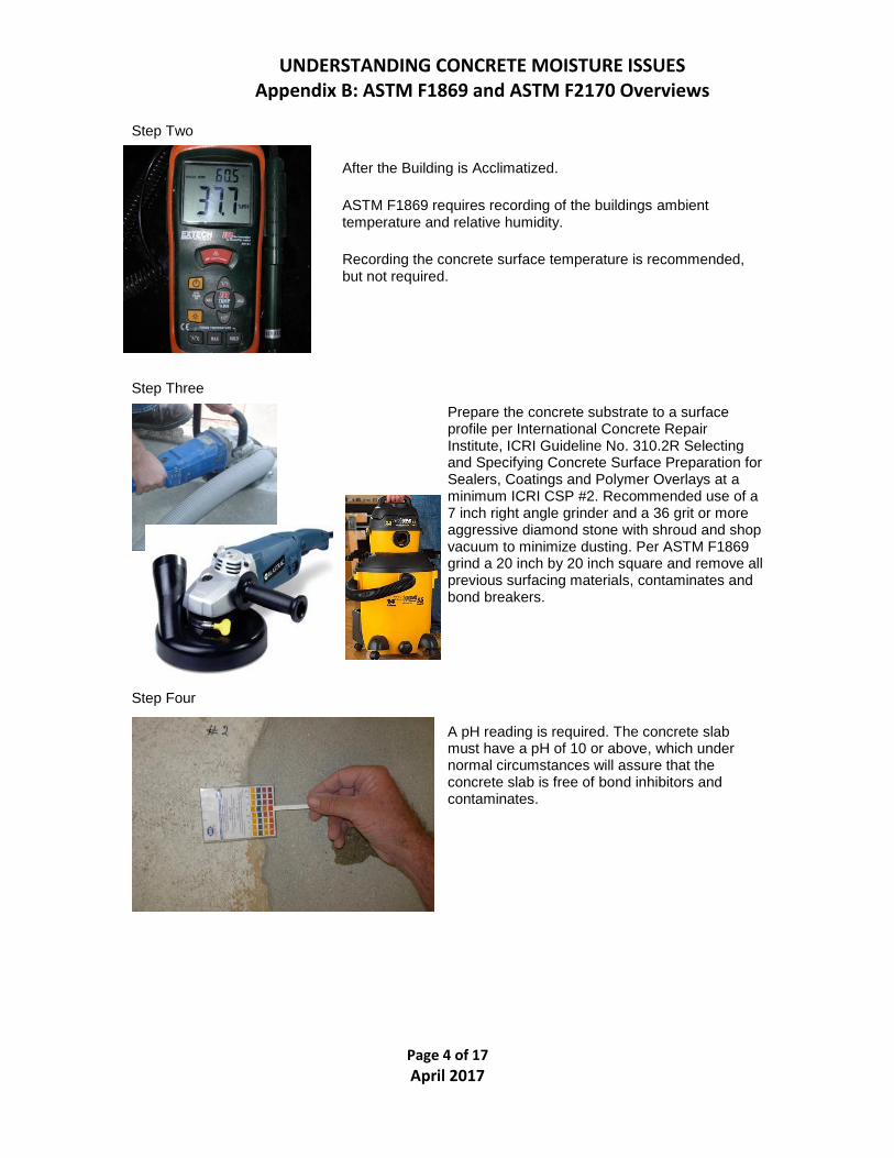
Step Two
After the Building is Acclimatized.
ASTM F1869 requires recording of the buildings ambient temperature and relative humidity.
Recording the concrete surface temperature is recommended, but not required.
Step Three Prepare the concrete substrate to a surface profile per International Concrete Repair Institute, ICRI Guideline No. 310.2R Selecting and Specifying Concrete Surface Preparation for Sealers, Coatings and Polymer Overlays at a minimum ICRI CSP #2. Recommended use of a 7 inch right angle grinder and a 36 grit or more aggressive diamond stone with shroud and shop vacuum to minimize dusting. Per ASTM F1869 grind a 20 inch by 20 inch square and remove all previous surfacing materials, contaminates and bond breakers.
Step Four
A pH reading is required. The concrete slab must have a pH of 10 or above, which under normal circumstances will assure that the concrete slab is free of bond inhibitors and contaminates.

UNDERSTANDING CONCRETE MOISTURE ISSUES Appendix B: ASTM F1869 and ASTM F2170 Overviews
Page 5 of 17 April 2017
Step Five
Calcium Chloride Test Kit Digital Gram Scale
Open the sealed bag containing the calcium chloride canister. Weigh the canister with the tape seal still on the canister using a gram scale with a gradation to 1/10th gram. Be sure the scale is set to grams (Note: Ounce weight scales will not be accurate enough to work for this test). Starting weights are usually around 30 to 31 grams, but may vary. The main concern in weighing this test canister is using the same scale when the first weigh the canister as post-test weight. The overall gain in grams is most important factor.
Step Six
Record the starting weight, date, time, temperature and relative humidity when starting the test on the canister lid and on the back of the worksheet provided with the test kit. The most important factor is determining the gain in grams from the start to finish of the test and the hours of exposure.

UNDERSTANDING CONCRETE MOISTURE ISSUES Appendix B: ASTM F1869 and ASTM F2170 Overviews
Page 6 of 17 April 2017
Step Seven:
Peel off the protective backing on the tape from the dome sealant material and discard the backing. Be sure the sealant material does not contact objects or clothing as it is very sticky and is intended to provide a secure, long lasting seal to the concrete throughout the duration of the test.
Step Eight
Carefully remove the canister tape, carefully wrap the tape around the lid for “safe and clean keeping” and prepare to start the test. Make sure the tape does not pick up dirt or get lost since it will be needed to reseal the container at the termination of the test.
Do not spill the calcium chloride crystals. If crystals are lost, reweigh the plastic dish, lid, tape and remaining crystals. If ten percent or more is lost, discard the test kit.
Place the lid under the dish as shown and wrap tape around lid and dish.
Note: Take care to keep tape clean.

UNDERSTANDING CONCRETE MOISTURE ISSUES Appendix B: ASTM F1869 and ASTM F2170 Overviews
Page 7 of 17 April 2017
Step Nine
Install the test kit at the center of the concrete floor. Place the opened calcium chloride container on the concrete floor, in the center of 20 inch square. Make sure the crystals inside are relatively level. If any of the crystals are spilled the test can be invalid. Spilled crystals must be vacuumed up quickly before leaving a damp residue.
Step Ten
Immediately place the dome cover over the center of the dish unit. Always be prepared to place the dome and dish as soon as possible after opening the dish. Press down firmly along all the edges of the sealant material to securely bond the unit to the floor. A properly sealed dome will have the outside flange touching the floor. Put a slight amount of hand pressure on the center of the dome to ensure it is not leaking or absorbing air because of a poor fit. It is a good idea is to duct tape the dome edges in place to minimize disturbance.
Step Eleven
Allow the test to remain in place and undisturbed for 60 to 72 hours, prefer 72 hours. Once the test is placed into service it must not be disturbed by foot traffic or allowed to be exposed to direct sunlight. If accidental bumping occurs and the seal is not broken or the crystals inside spilled, the test may still be useable. If exposed to sunlight it will bias the test and produce inaccurate results. The use of protective cones is a good way to draw more attention to the test kit. It is a good idea to inform people that this test is sensitive and may have to be re-conducted if disturbed or destroyed.
Step Twelve
Recover the dish after exposure and calculate the results. At the end of the 60 to 72 hours of exposure, carefully open the dome with a razor blade and reach inside to retrieve the dish without spilling the calcium chloride. The used dome and sealant can be safely removed from the concrete with a razor scraper later on.

UNDERSTANDING CONCRETE MOISTURE ISSUES Appendix B: ASTM F1869 and ASTM F2170 Overviews
Page 8 of 17 April 2017
Step Thirteen
Immediately replace the dish lid and use the sealing tape to re-seal the dish. Re-weigh the dish on the same gram scale used at the start of the test, and once again record the weight and time on the dish lid and on the worksheet.
Step Fourteen
Subtract the Starting Weight from the Ending Weight to find the Weight Gained.
Multiply the Weight Gained by 117.707, then divide that number by the hours tested.
4.8 (weight gained) x 177.707
72 hours
Results Equal 7.8 pounds per 1,000 square feet

UNDERSTANDING CONCRETE MOISTURE ISSUES Appendix B: ASTM F1869 and ASTM F2170 Overviews
Page 9 of 17 April 2017
Step Fifteen - Report

UNDERSTANDING CONCRETE MOISTURE ISSUES Appendix B: ASTM F1869 and ASTM F2170 Overviews
Page 10 of 17 April 2017
UNDERSTANDING ASTM F2170 Relative Humidity in situ Test ASTM F2170 testing in a nutshell:
• Testing at the facility must be at the service temperature of its intended operating conditions.
• The tests must be placed randomly, but usually for convenience are placed out of the way of other trades.
• First 1,000 square feet (92.9 square meters) must be tested in 3 places. • Next 1,000 square feet (92.9 square meters) or part thereof must be tested in 1 place.
The in situ relative humidity test is conducted according to the test method specified in ASTM F2170, Determining Relative Humidity in Concrete Floor Slabs Using in situ Probes. ASTM F2170 measures the relative humidity in the slab at a depth that would be equivalent to the RH that would exist in the slab after installation of an impermeable floor covering.
To perform this test correctly the person doing the testing must know the depth of the concrete slab, since it is critical for the depth of placement of the relative humidity probes. The drill depth from the top of the concrete slab on grade will be 40% of the concrete slabs thickness. The drill depth of an elevated slab, not poured on and left in place metal form, that can freely dry both top and bottom at 20% of the concrete slabs thickness.
Example #1. If the concrete slab is 6 inches (15.2 cm) thick and poured on-grade then the bottom of the probe hole should be 40% of the concrete slab thickness about 2.4 inches (6.35 cm) deep. Example #2. If the elevated concrete slab is 12 inches (30.5 cm) thick and free to dry on the top and bottom, then the bottom of the probe hole should be 20% of the concrete slab thickness about 2.4 inches (6.35 cm) deep.
Acclimatized Most relative humidity probe providers fail to mention that acclimation of the building is Step 1. They immediately start with drilling as the first step. Acclimation must be done before “drilling begins” and several other steps should be performed before drilling with a roto-hammer begins.

UNDERSTANDING CONCRETE MOISTURE ISSUES Appendix B: ASTM F1869 and ASTM F2170 Overviews
Page 11 of 17 April 2017
STEPS: Step 1. Determine the depth of slab Step 2. Acclimatize the Building Step 3. Take Ambient Temperature and Relative Humidity at the Drill Site, and take the Concrete Slab Surface Temperature with an Infrared Gauge. Step 4. Use 3/4 inch (1.9 cm) Concrete Drill Bit in an Industrial Roto-Hammer

UNDERSTANDING CONCRETE MOISTURE ISSUES Appendix B: ASTM F1869 and ASTM F2170 Overviews
Page 12 of 17 April 2017
Step 5. Mark Drill Bit with Tape (a good idea with or without a depth gauge)
Step 6. Drill Hole with a Roto-Hammer and the depth gauge or “Depth Restraint Bar” in Place
Step 7. Clean the Probe Hole

UNDERSTANDING CONCRETE MOISTURE ISSUES Appendix B: ASTM F1869 and ASTM F2170 Overviews
Page 13 of 17 April 2017
Step 8. Optional Digital-Optical Inspections of Probe Hole
Step 9. Install Probe and Record Probe Number on Data Log.

UNDERSTANDING CONCRETE MOISTURE ISSUES Appendix B: ASTM F1869 and ASTM F2170 Overviews
Page 14 of 17 April 2017
Step 10. Record Test Collection Data

UNDERSTANDING CONCRETE MOISTURE ISSUES Appendix B: ASTM F1869 and ASTM F2170 Overviews
Page 15 of 17 April 2017
Step 11. Protect Probe with Plastic Cap and Caution Tape to Keep Other Trades from Distributing the Test
Step 12. Read Temperature and Relativity Humidity at 72 Hours
An Error Code will appear if Relative Humidity is 100%.

UNDERSTANDING CONCRETE MOISTURE ISSUES Appendix B: ASTM F1869 and ASTM F2170 Overviews
Page 16 of 17 April 2017
Report 13. Test Report
QUESTIONS Feel free to contact APF if you have questions.

UNDERSTANDING CONCRETE MOISTURE ISSUES Appendix B: ASTM F1869 and ASTM F2170 Overviews
Page 17 of 17 April 2017
Disclaimer: APF Technical Guidelines are developed in good faith for the sole purpose of assisting others with products, systems and industry standards. The information published herein is gathered from different sources that are thought to be reliable, but the reader should not assume that the information absolves the reader from validating information from other sources, such as listed below, before making a decision. Since information from others can change without notice, APF cannot be held at fault if any of the information conveyed in good faith is deemed in error.
References: ASTM D4263 Standard Test Method for Indicating Moisture in Concrete by the Plastic Sheet Method ASTM F1869 - Standard Test Method for Measuring Moisture Vapor Emission Rate of Concrete Subfloor Using Anhydrous Calcium Chloride
ASTM F2170 Standard Test Method for Determining Relative Humidity in Concrete Floor Slabs using in situ Probes ASTM International (formerly American Society for Testing of Materials) 100 Barr Harbor Dr., West Cohshohocken, PA 19428 (http://www.astm.org)