Embed Size (px)
Citation preview
API PIPING PLANS
www.aesseal.comThe API Plans elaborated in this section are as defined by API 682 3rd edition / API 610 10th
edition. These are standardized flushing piping arrangements that are widely used in theindustry. Customer specific variants of these plans are possible.
Please contact AESSEAL® Systems division for further details.Tel: +44 (0)28 9266 9966 Email: [email protected]
“To check out mechanical seal flushing arrangements and piping plans,I have consistently found this to be the most useful and permanentpocket-sized document. This high-quality booklet comprehensivelydescribes both configurational parameters and application criteria”.
Heinz P. Bloch P.E.Independent Professional Engineer •
01 02 11
32 4131
12 13 14 21
22 23
51 61
71
72 74
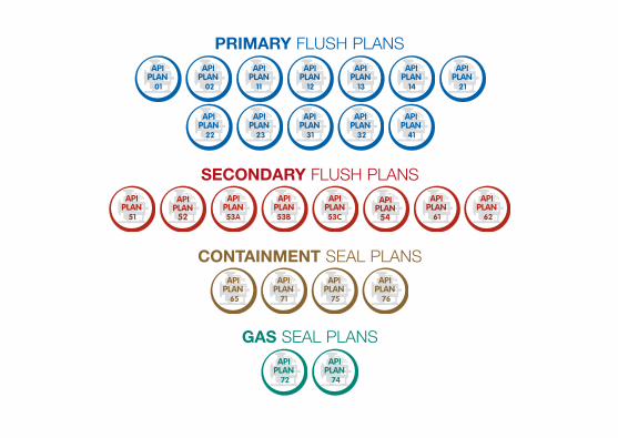
PRIMARY FLUSH PLANS
SECONDARY FLUSH PLANS
GAS SEAL PLANS
CONTAINMENT SEAL PLANS
62
65

“Of all the worlds water 97.4% is salt water, 2% is solid in ice caps and only 0.6% is suitable
for industrial use and human consumption.”
Conserve Water
0.6%
•
PR
IMA
RY
FLUS
H P
LAN
S
01
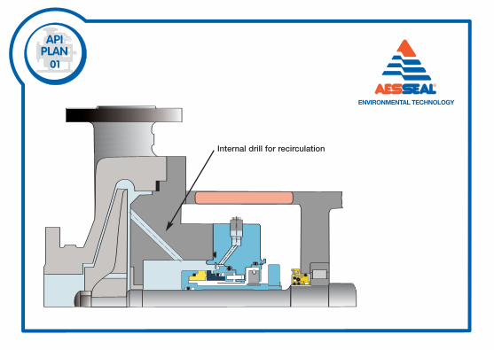
Internal drill for recirculation
DescriptionIntegrated (internal) product recirculation from pump discharge to seal chamber.
Features1. Minimizes risk of freezing / polymerizing of fluid in flush piping plans exposed to atmosphere.2. Removes heat from the seal chamber as well as acting as a vent connection in horizontal pumps.
Use1. Recommended in clean fluids.2. Recommended for fluids which thicken at ambient temperature.
Caution1. Ensure that the recirculation is sufficient for seal heat removal.
API PLAN 01
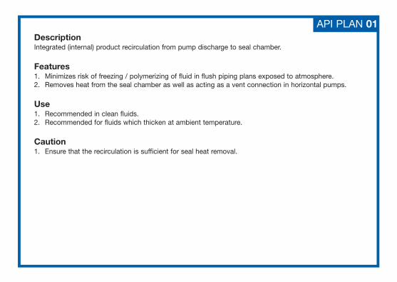
02
DescriptionDead ended seal chamber with no flush fluid circulation.
Features1. Applicable to low seal chamber pressure and process temperature.2. Can be used with tapered seal chambers, especially for slurries.3. Normally is used along with a jacketed seal chamber.
Use1. In cool clean fluids with high specific heat, such as water, in relatively low speed pumps.
Caution1. To avoid flashing, process fluid temperature must be taken into consideration.2. Avoid use without cooling / heating jacket (for cylindrical chambers).3. Ensure top point vent in throat bush (for cylindrical chambers in horizontal pumps).
API PLAN 02
11
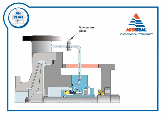
Flow controlorifice

API PLAN 11DescriptionProduct recirculation from pump discharge to seal through a flow control orifice.
Features1. Prevents product from vaporizing by maintaining positive pressure above vapor pressure.2. Becomes a self-venting plan for horizontal pumps.3. Default API Plan for most single seals.
Use1. In general, applications with clean non-polymerizing fluids with moderate temperatures.
Caution1. Calculation of recirculation flow rate, heat removal and orifice size are required.2. Orifice size should be at least 1/8” (3.2mm).3. Check the margin between discharge pressure & seal chamber pressure to ensure proper flow of fluid.4. Do not use with media containing solids & abrasives.
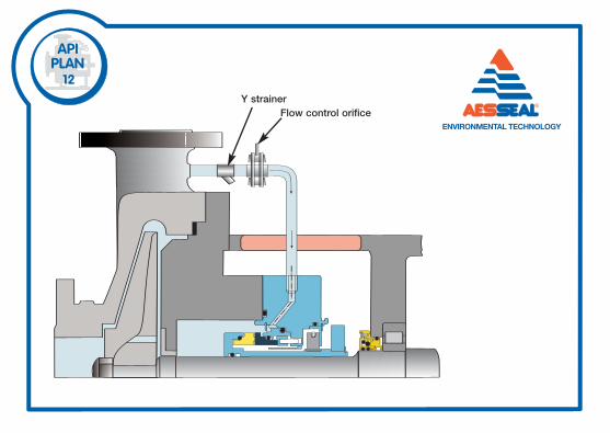
12Y strainer
Flow control orifice
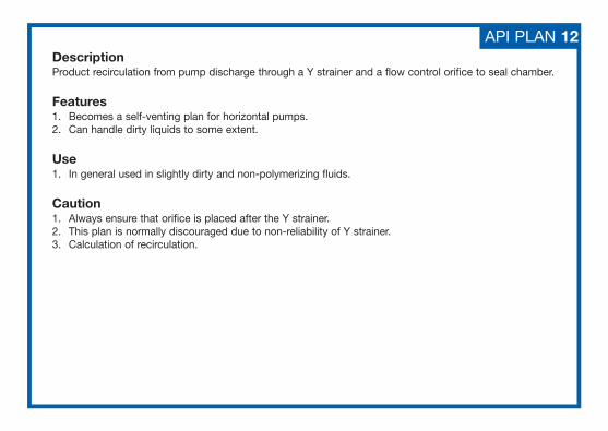
DescriptionProduct recirculation from pump discharge through a Y strainer and a flow control orifice to seal chamber.
Features1. Becomes a self-venting plan for horizontal pumps.2. Can handle dirty liquids to some extent.
Use1. In general used in slightly dirty and non-polymerizing fluids.
Caution1. Always ensure that orifice is placed after the Y strainer.2. This plan is normally discouraged due to non-reliability of Y strainer.3. Calculation of recirculation.
API PLAN 12
13
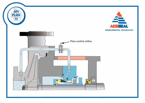
Flow control orifice
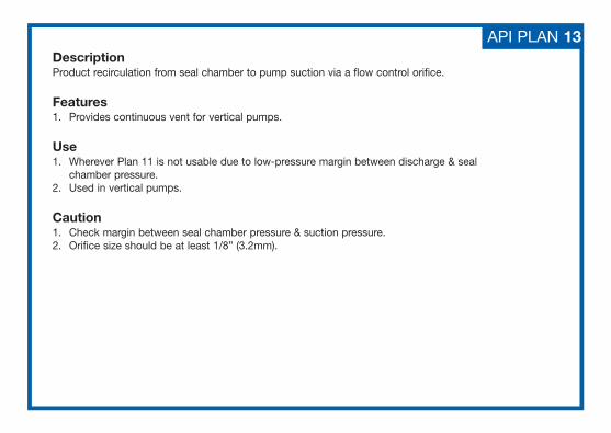
DescriptionProduct recirculation from seal chamber to pump suction via a flow control orifice.
Features1. Provides continuous vent for vertical pumps.
Use1. Wherever Plan 11 is not usable due to low-pressure margin between discharge & seal
chamber pressure.2. Used in vertical pumps.
Caution1. Check margin between seal chamber pressure & suction pressure.2. Orifice size should be at least 1/8” (3.2mm).
API PLAN 13
14
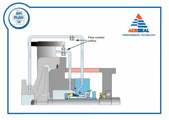
Flow controlorifice
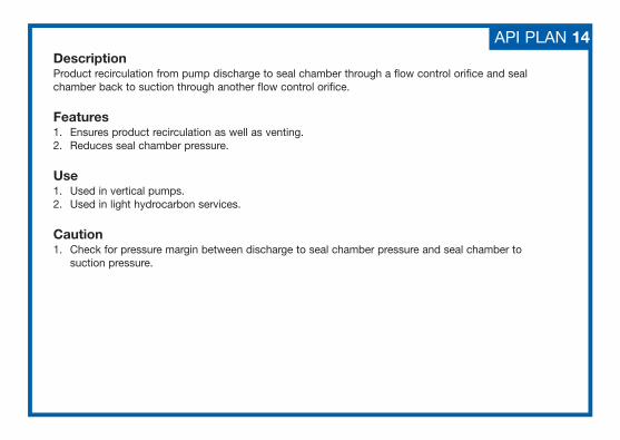
DescriptionProduct recirculation from pump discharge to seal chamber through a flow control orifice and sealchamber back to suction through another flow control orifice.
Features1. Ensures product recirculation as well as venting.2. Reduces seal chamber pressure.
Use1. Used in vertical pumps.2. Used in light hydrocarbon services.
Caution1. Check for pressure margin between discharge to seal chamber pressure and seal chamber to
suction pressure.
API PLAN 14
21
T
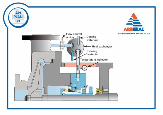
Flow controlorifice
Heat exchanger
Temperature indicator
Coolingwater out
Coolingwater in
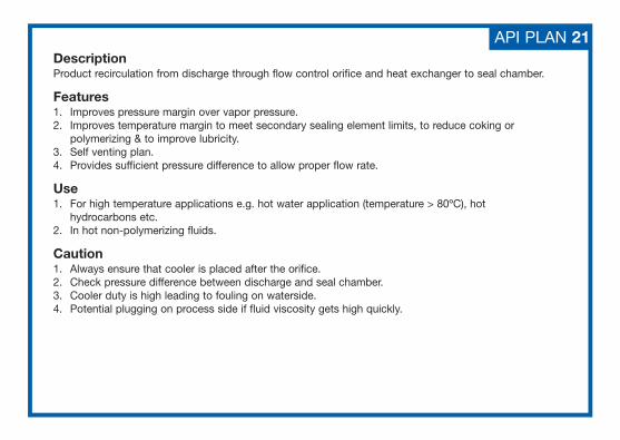
DescriptionProduct recirculation from discharge through flow control orifice and heat exchanger to seal chamber.
Features1. Improves pressure margin over vapor pressure.2. Improves temperature margin to meet secondary sealing element limits, to reduce coking or
polymerizing & to improve lubricity.3. Self venting plan.4. Provides sufficient pressure difference to allow proper flow rate.
Use1. For high temperature applications e.g. hot water application (temperature > 80ºC), hot
hydrocarbons etc.2. In hot non-polymerizing fluids.
Caution1. Always ensure that cooler is placed after the orifice.2. Check pressure difference between discharge and seal chamber.3. Cooler duty is high leading to fouling on waterside.4. Potential plugging on process side if fluid viscosity gets high quickly.
API PLAN 21
T
22Flow control orifice
Heat exchanger
Cooling water in
Temperature indicator
Cooling water out
Y strainer
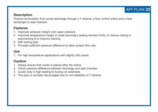
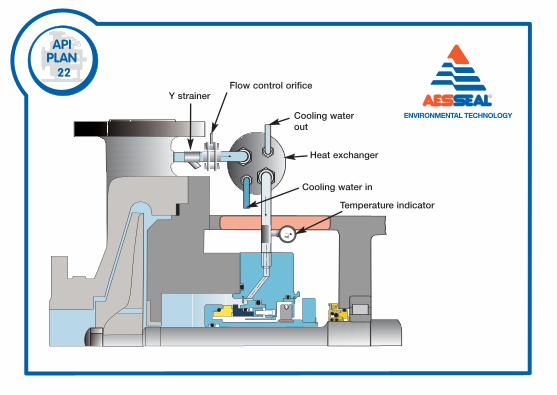
DescriptionProduct recirculation from pump discharge through a Y strainer, a flow control orifice and a heatexchanger to seal chamber.
Features1. Improves pressure margin over vapor pressure.2. Improves temperature margin to meet secondary sealing element limits, to reduce coking or
polymerizing & to improve lubricity.3. Self venting plan.4. Provides sufficient pressure difference to allow proper flow rate.
Use1. For high temperature applications with slightly dirty liquid.
Caution1. Always ensure that cooler is placed after the orifice.2. Check pressure difference between discharge and seal chamber.3. Cooler duty is high leading to fouling on waterside.4. This plan is normally discouraged due to non-reliability of Y strainer.
API PLAN 22
23
T
Heatexchanger
Temperatureindicator
Pumpingring
Coolingwater in
Cooling water out
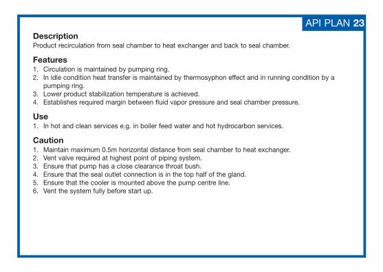
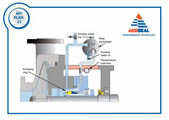
API PLAN 23DescriptionProduct recirculation from seal chamber to heat exchanger and back to seal chamber.
Features1. Circulation is maintained by pumping ring.2. In idle condition heat transfer is maintained by thermosyphon effect and in running condition by a
pumping ring.3. Lower product stabilization temperature is achieved.4. Establishes required margin between fluid vapor pressure and seal chamber pressure.
Use1. In hot and clean services e.g. in boiler feed water and hot hydrocarbon services.
Caution1. Maintain maximum 0.5m horizontal distance from seal chamber to heat exchanger.2. Vent valve required at highest point of piping system.3. Ensure that pump has a close clearance throat bush.4. Ensure that the seal outlet connection is in the top half of the gland.5. Ensure that the cooler is mounted above the pump centre line.6. Vent the system fully before start up.
31
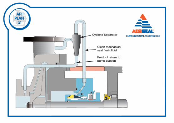
Cyclone Separator
Product return topump suction
Clean mechanicalseal flush fluid
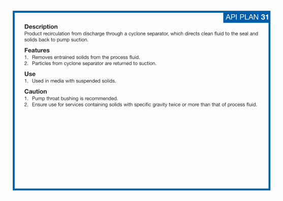
DescriptionProduct recirculation from discharge through a cyclone separator, which directs clean fluid to the seal andsolids back to pump suction.
Features1. Removes entrained solids from the process fluid.2. Particles from cyclone separator are returned to suction.
Use1. Used in media with suspended solids.
Caution1. Pump throat bushing is recommended.2. Ensure use for services containing solids with specific gravity twice or more than that of process fluid.
API PLAN 31
5
10
1T
P
32
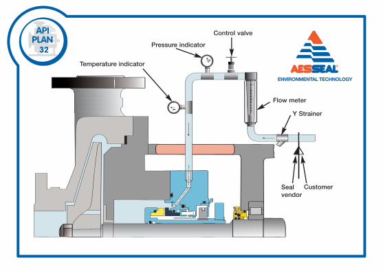
Control valve
Pressure indicator
Temperature indicator
Flow meter
Y Strainer
CustomerSeal vendor
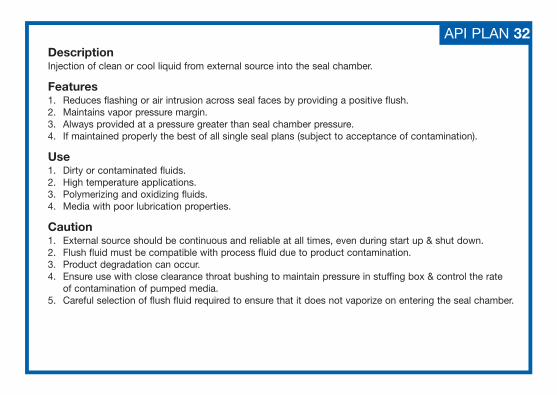
DescriptionInjection of clean or cool liquid from external source into the seal chamber.
Features1. Reduces flashing or air intrusion across seal faces by providing a positive flush.2. Maintains vapor pressure margin.3. Always provided at a pressure greater than seal chamber pressure.4. If maintained properly the best of all single seal plans (subject to acceptance of contamination).
Use1. Dirty or contaminated fluids.2. High temperature applications.3. Polymerizing and oxidizing fluids.4. Media with poor lubrication properties.
Caution1. External source should be continuous and reliable at all times, even during start up & shut down.2. Flush fluid must be compatible with process fluid due to product contamination.3. Product degradation can occur.4. Ensure use with close clearance throat bushing to maintain pressure in stuffing box & control the rate
of contamination of pumped media.5. Careful selection of flush fluid required to ensure that it does not vaporize on entering the seal chamber.
API PLAN 32
41
Heat exchanger
Cooling water in
Cyclone separator
Cooling water out
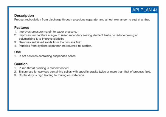
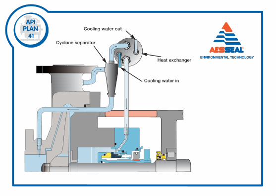
DescriptionProduct recirculation from discharge through a cyclone separator and a heat exchanger to seal chamber.
Features1. Improves pressure margin to vapor pressure.2. Improves temperature margin to meet secondary sealing element limits, to reduce coking or
polymerizing & to improve lubricity.3. Removes entrained solids from the process fluid.4. Particles from cyclone separator are returned to suction.
Use1. In hot services containing suspended solids.
Caution1. Pump throat bushing is recommended.2. Ensure use for services containing solids with specific gravity twice or more than that of process fluid.3. Cooler duty is high leading to fouling on waterside.
API PLAN 41
“AESSEAL® Seal Support Systems currently save global industry in excess of
5 billion gal (US) / 19 billion liters of water per year.”
Water Savings
19billionliters
•
SE
CO
ND
AR
YFLU
SH
PLA
NS
51
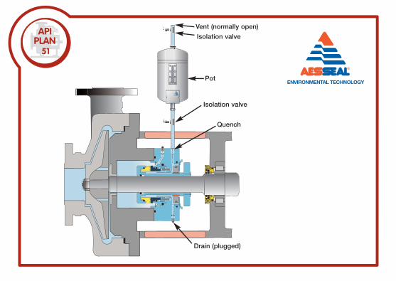
Vent (normally open)
Isolation valve
Isolation valve
Quench
Drain (plugged)
Pot
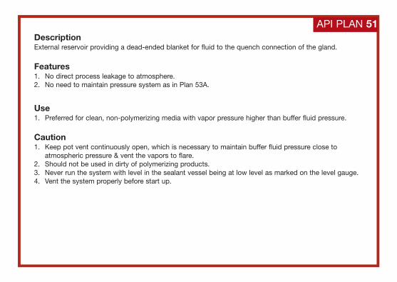
DescriptionExternal reservoir providing a dead-ended blanket for fluid to the quench connection of the gland.
Features1. No direct process leakage to atmosphere.2. No need to maintain pressure system as in Plan 53A.
Use1. Preferred for clean, non-polymerizing media with vapor pressure higher than buffer fluid pressure.
Caution1. Keep pot vent continuously open, which is necessary to maintain buffer fluid pressure close to
atmospheric pressure & vent the vapors to flare.2. Should not be used in dirty of polymerizing products.3. Never run the system with level in the sealant vessel being at low level as marked on the level gauge.4. Vent the system properly before start up.
API PLAN 51
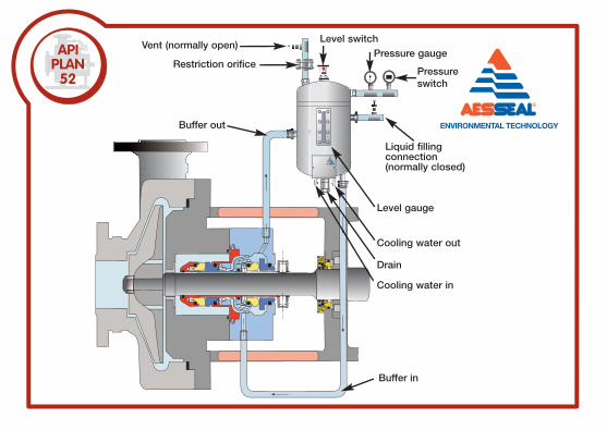
Level switchVent (normally open)
Restriction orifice
Buffer out
Liquid fillingconnection(normally closed)
Level gauge
Cooling water out
Drain
Cooling water in
Buffer in
Pressure gauge
Pressureswitch
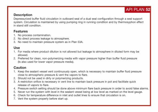
DescriptionDepressurized buffer fluid circulation in outboard seal of a dual seal configuration through a seal supportsystem. Circulation is maintained by using pumping ring in running condition and by thermosyphon effect in stand still condition.
Features1. No process contamination.2. No direct process leakage to atmosphere.3. No need to maintain pressure system as in Plan 53A.
Use1. For media where product dilution is not allowed but leakage to atmosphere in diluted form may be
allowed.2. Preferred for clean, non-polymerizing media with vapor pressure higher than buffer fluid pressure
(Is also used for lower vapor pressure media).
Caution1. Keep the sealant vessel vent continuously open, which is necessary to maintain buffer fluid pressure
close to atmospheric pressure & vent the vapors to flare.2. Should not be used in dirty or polymerizing products.3. A restriction orifice is necessary in vent line to maintain back pressure in pot and facilitate quick
release of vapors to flare.4. Pressure switch setting should be done above minimum flare back pressure in order to avoid false alarms.5. Never run the system with level in the sealant vessel being at low level as marked on the level gauge.6. Check for temperature difference in inlet and outlet lines to ensure that circulation is on.7. Vent the system properly before start up.
API PLAN 52
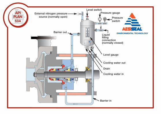
Level switchExternal nitrogen pressure
source (normally open)
Barrier outLiquidfillingconnection(normally closed)
Level gauge
Cooling water out
Drain
Cooling water in
Barrier in
Pressureswitch
Pressure gauge
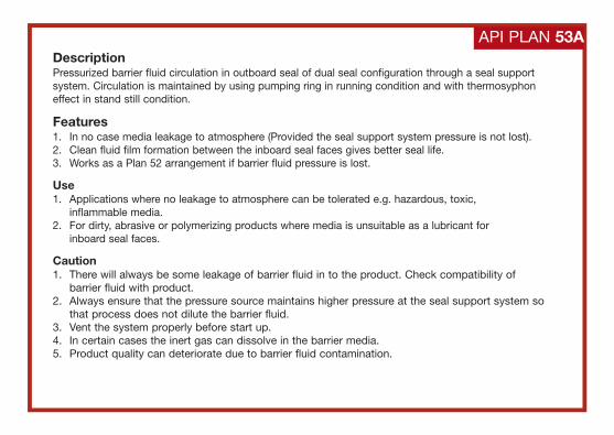
DescriptionPressurized barrier fluid circulation in outboard seal of dual seal configuration through a seal supportsystem. Circulation is maintained by using pumping ring in running condition and with thermosyphoneffect in stand still condition.
Features1. In no case media leakage to atmosphere (Provided the seal support system pressure is not lost).2. Clean fluid film formation between the inboard seal faces gives better seal life.3. Works as a Plan 52 arrangement if barrier fluid pressure is lost.
Use1. Applications where no leakage to atmosphere can be tolerated e.g. hazardous, toxic,
inflammable media.2. For dirty, abrasive or polymerizing products where media is unsuitable as a lubricant for
inboard seal faces.
Caution1. There will always be some leakage of barrier fluid in to the product. Check compatibility of
barrier fluid with product.2. Always ensure that the pressure source maintains higher pressure at the seal support system so
that process does not dilute the barrier fluid.3. Vent the system properly before start up.4. In certain cases the inert gas can dissolve in the barrier media.5. Product quality can deteriorate due to barrier fluid contamination.
API PLAN 53A
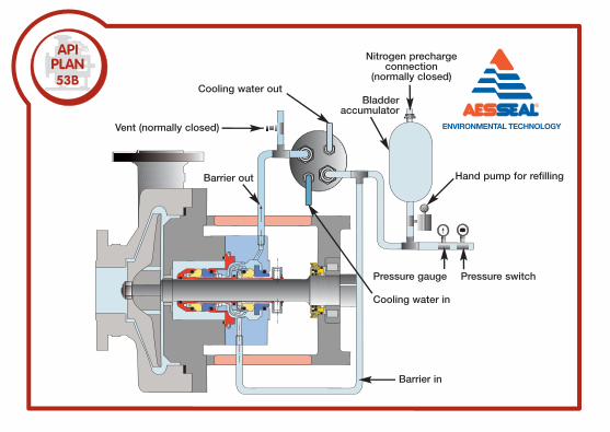
Pressure switch
Cooling water in
Barrier in
Pressure gauge
Bladder accumulator
Cooling water out
Vent (normally closed)
Barrier out Hand pump for refilling
Nitrogen prechargeconnection
(normally closed)
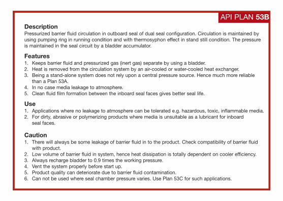
DescriptionPressurized barrier fluid circulation in outboard seal of dual seal configuration. Circulation is maintained byusing pumping ring in running condition and with thermosyphon effect in stand still condition. The pressureis maintained in the seal circuit by a bladder accumulator.
Features1. Keeps barrier fluid and pressurized gas (inert gas) separate by using a bladder.2. Heat is removed from the circulation system by an air-cooled or water-cooled heat exchanger.3. Being a stand-alone system does not rely upon a central pressure source. Hence much more reliable
than a Plan 53A.4. In no case media leakage to atmosphere.5. Clean fluid film formation between the inboard seal faces gives better seal life.
Use1. Applications where no leakage to atmosphere can be tolerated e.g. hazardous, toxic, inflammable media.2. For dirty, abrasive or polymerizing products where media is unsuitable as a lubricant for inboard
seal faces.
Caution1. There will always be some leakage of barrier fluid in to the product. Check compatibility of barrier fluid
with product.2. Low volume of barrier fluid in system, hence heat dissipation is totally dependent on cooler efficiency.3. Always recharge bladder to 0.9 times the working pressure.4. Vent the system properly before start up.5. Product quality can deteriorate due to barrier fluid contamination.6. Can not be used where seal chamber pressure varies. Use Plan 53C for such applications.
API PLAN 53B
LS
L
P
Barrier in
Barrier out
Referencepressure line
Pressurerelief valve
Vent normally closed
Cooling water in
Cooling water out
Pressure switch
Pressure gauge
Level switch (low)
Piston typeaccumulator
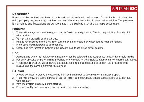
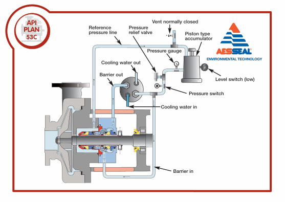
DescriptionPressurized barrier fluid circulation in outboard seal of dual seal configuration. Circulation is maintained by using pumping ring in running condition and with thermosyphon effect in stand still condition. The pressure is maintained and fluctuations are compensated in the seal circuit by a piston type accumulator.
Features1. There will always be some leakage of barrier fluid in to the product. Check compatibility of barrier fluid
with product.2. Vent system properly before start up.3. Heat is removed from the circulation system by an air-cooled or water-cooled heat exchanger.4. In no case media leakage to atmosphere.5. Clean fluid film formation between the inboard seal faces gives better seal life.
Use1. Applications where no leakage to atmosphere can be tolerated e.g. hazardous, toxic, inflammable media.2. For dirty, abrasive or polymerizing products where media is unsuitable as a lubricant for inboard seal faces.3. Where pump pressure varies during operation needing an auto setting of barrier fluid pressure, thus
maintaining the same differential throughout.
Caution1. Always connect reference pressure line from seal chamber to accumulator and keep it open.2. There will always be some leakage of barrier fluid in to the product. Check compatibility of barrier fluid
with product.3. Vent the system properly before start up.4. Product quality can deteriorate due to barrier fluid contamination.
API PLAN 53C
From externalpressure source
Barrier in
Barrier out
To externalpressure source
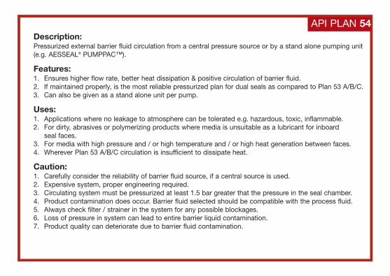
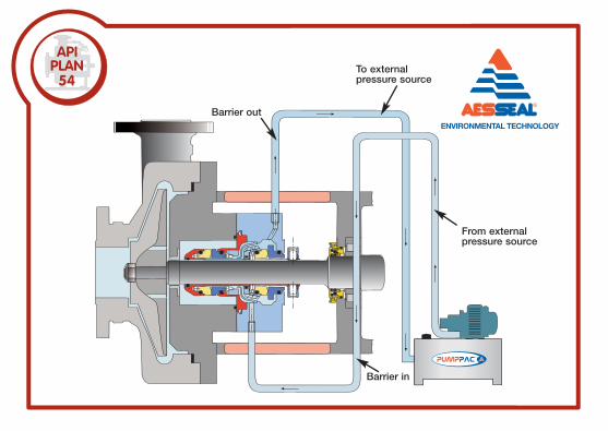
Description:Pressurized external barrier fluid circulation from a central pressure source or by a stand alone pumping unit(e.g. AESSEAL® PUMPPAC™).
Features:1. Ensures higher flow rate, better heat dissipation & positive circulation of barrier fluid.2. If maintained properly, is the most reliable pressurized plan for dual seals as compared to Plan 53 A/B/C.3. Can also be given as a stand alone unit per pump.
Uses:1. Applications where no leakage to atmosphere can be tolerated e.g. hazardous, toxic, inflammable.2. For dirty, abrasives or polymerizing products where media is unsuitable as a lubricant for inboard
seal faces.3. For media with high pressure and / or high temperature and / or high heat generation between faces.4. Wherever Plan 53 A/B/C circulation is insufficient to dissipate heat.
Caution:1. Carefully consider the reliability of barrier fluid source, if a central source is used.2. Expensive system, proper engineering required.3. Circulating system must be pressurized at least 1.5 bar greater that the pressure in the seal chamber.4. Product contamination does occur. Barrier fluid selected should be compatible with the process fluid.5. Always check filter / strainer in the system for any possible blockages.6. Loss of pressure in system can lead to entire barrier liquid contamination.7. Product quality can deteriorate due to barrier fluid contamination.
API PLAN 54
61
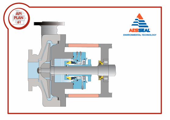
API PLAN 61DescriptionPlugged connections for future use for Plan 62 or Plan 65.
Features1. The drain connection can be piped in order to collect leakage and use as Plan 65.2. Both quench & drain can be piped and used as quench in and out connection as Plan 62.
Use1. For future provision.
Caution1. Always keep ports plugged.
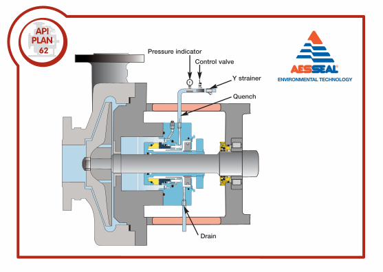
62 Pressure indicator
Control valve
Drain
Y strainer
Quench
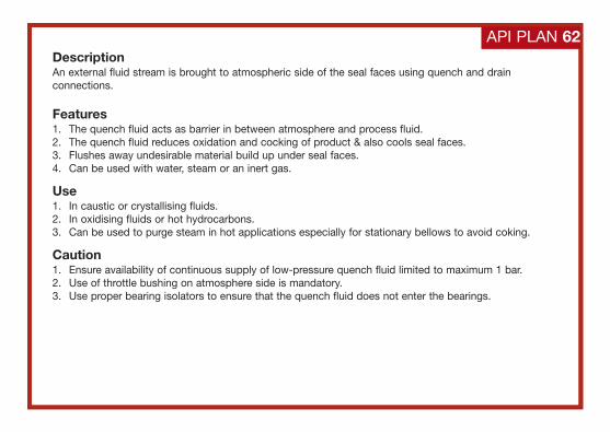
DescriptionAn external fluid stream is brought to atmospheric side of the seal faces using quench and drainconnections.
Features1. The quench fluid acts as barrier in between atmosphere and process fluid.2. The quench fluid reduces oxidation and cocking of product & also cools seal faces.3. Flushes away undesirable material build up under seal faces.4. Can be used with water, steam or an inert gas.
Use1. In caustic or crystallising fluids.2. In oxidising fluids or hot hydrocarbons.3. Can be used to purge steam in hot applications especially for stationary bellows to avoid coking.
Caution1. Ensure availability of continuous supply of low-pressure quench fluid limited to maximum 1 bar.2. Use of throttle bushing on atmosphere side is mandatory.3. Use proper bearing isolators to ensure that the quench fluid does not enter the bearings.
API PLAN 62
Charity registrationnumber 288701
AESSEAL® feel that the environmental impact of global waterconcern is too big an issue to ignore. WaterAid is an international
charity dedicated to their vision of helping people all over theglobe escape the stronghold of poverty & disease caused by
living without water and sanitation. AESSEAL® share in this vision and as a result we have entered into an agreement with
WaterAid, where we donate a percentage of our profits from Seal Support Systems to the charity. This means that when you
install a Seal Support System you are helping WaterAid toprovide clean water and sanitation to those who really need it.
www.wateraid.org
Environmental Benefit •
CO
NTA
INM
EN
TS
EA
L PLA
NS
LSH
65
Leakage collection vessel
Restriction orifice
Pressurecontrolvalve
Controlvalve
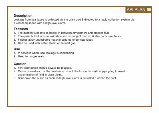
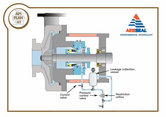
DescriptionLeakage from seal faces is collected via the drain port & directed to a liquid collection system via a vessel equipped with a high-level alarm.
Features1. The quench fluid acts as barrier in between atmosphere and process fluid.2. The quench fluid reduces oxidation and cocking of product & also cools seal faces.3. Flushes away undesirable material build up under seal faces.4. Can be used with water, steam or an inert gas.
Use1. In services where seal leakage is condensing.2. Used for single seals.
Caution1. Vent connection should always be plugged.2. Orifice downstream of the level switch should be located in vertical piping leg to avoid
accumulation of fluid in drain piping.3. Shut down the pump as soon as high-level alarm is activated & attend the seal.
API PLAN 65
71
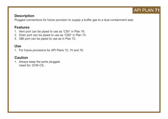
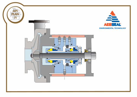
API PLAN 71DescriptionPlugged connections for future provision to supply a buffer gas to a dual containment seal.
Features1. Vent port can be piped to use as ‘CSV’ in Plan 76.2. Drain port can be piped to use as ‘CSD’ in Plan 75.3. GBI port can be piped to use as in Plan 72.
Use1. For future provisions for API Plans 72, 75 and 76.
Caution1. Always keep the ports plugged.
Used for: 2CW-CS.
LSH
PSH
Gas buffer in (GBI)
To flare
Customer
Seal vendor
Restrictionorifice plate
Isolation valve
Drain valveReservoir
Levelswitch high Level gauge
Control valve
Gas barrier out (GBO)
Flush
Pressure gauge
Containment seal vent (CSV)
Test connection(normally closed)
Pressure switch high
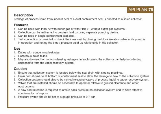
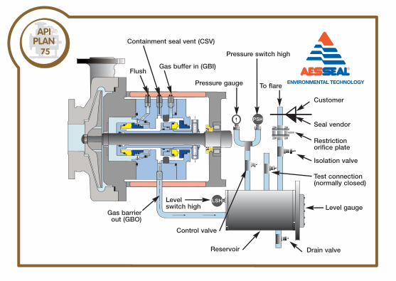
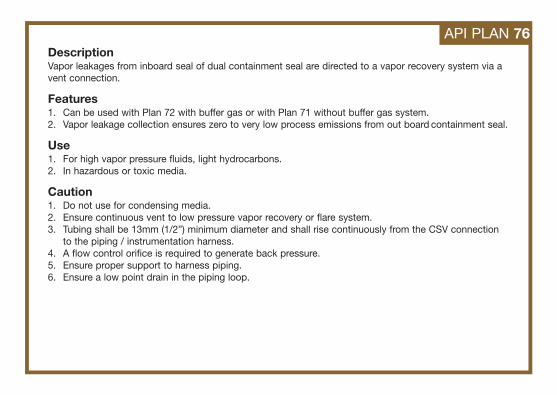
DescriptionLeakage of process liquid from inboard seal of a dual containment seal is directed to a liquid collector.
Features1 Can be used with Plan 72 with buffer gas or with Plan 71 without buffer gas systems.2. Collection can be redirected to process fluid by using separate pumping device.3. Can be used in single containment seal also.4. Test connection is provided to check the inner seal by closing the block isolation valve while pump is
in operation and noting the time / pressure build-up relationship in the collector.
Use1. Duties with condensing leakages.2. Hazardous, toxic fluids.3. May also be used for non-condensing leakages. In such cases, the collector can help in collecting
condensate from the vapor recovery system.
Caution1. Ensure that collection system is located below the seal drain with sloping pipelines.2. Drain port should be at bottom of containment seal to allow the leakage to flow to the collection system.3. Collection system should always be vented releasing vapors of process liquid to vapor recovery system.4. Valves that are installed should be accessible to operator relative to ground clearance and other
obstructions.5. A flow control orifice is required to create back pressure on collection system and to have effective
condensation of vapors.6. Pressure switch should be set at a gauge pressure of 0.7 bar.
API PLAN 75
PSH
Pressure gauge
Drain valve
Gas buffer in (GBI)
Containment valve vent (CSV)
Flush
Seal vendor
CustomerIsolation valve (normally open)
Pressure switch high
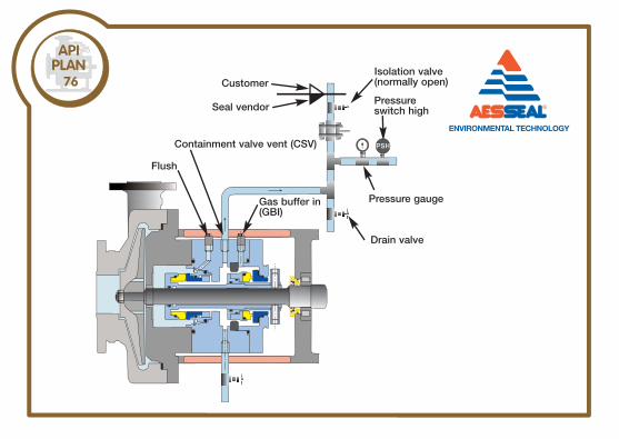
DescriptionVapor leakages from inboard seal of dual containment seal are directed to a vapor recovery system via avent connection.
Features1. Can be used with Plan 72 with buffer gas or with Plan 71 without buffer gas system.2. Vapor leakage collection ensures zero to very low process emissions from out board containment seal.
Use1. For high vapor pressure fluids, light hydrocarbons.2. In hazardous or toxic media.
Caution1. Do not use for condensing media.2. Ensure continuous vent to low pressure vapor recovery or flare system.3. Tubing shall be 13mm (1/2”) minimum diameter and shall rise continuously from the CSV connection
to the piping / instrumentation harness.4. A flow control orifice is required to generate back pressure.5. Ensure proper support to harness piping.6. Ensure a low point drain in the piping loop.
API PLAN 76
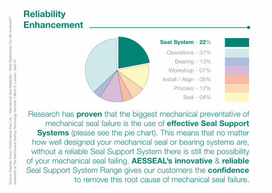
Research has proven that the biggest mechanical preventative ofmechanical seal failure is the use of effective Seal Support
Systems (please see the pie chart). This means that no matterhow well designed your mechanical seal or bearing systems are,without a reliable Seal Support System there is still the possibility
of your mechanical seal failing. AESSEAL’s innovative & reliableSeal Support System Range gives our customers the confidence
to remove this root cause of mechanical seal failure.
Seal - 04%
Process - 12%
Install / Align - 05%
Operations - 37%
Seal System - 22%
Workshop - 07%
Bearing - 13%
Sou
rce:
Ste
phe
n Fl
ood
, P
erfo
rman
ce P
lus
Ltd
- “
Mec
hani
cal S
eal R
elia
bili
ty-
Wha
t R
ealis
tical
ly C
anB
e A
chie
ved
?”p
rese
nted
at
The
Mec
hani
cal S
ealin
g Te
chno
logy
Sem
inar
, I M
ech
E,
Lond
on,
Ap
ril 0
7Reliability Enhancement •
GA
SS
EA
L PLA
NS
FSH
5
10
1
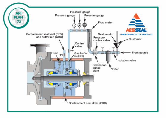
72
Pressure gaugePressure gauge
Pressure gauge
Flow meter
Pressure control valve
Seal vendor
From source
Isolation valve
FilterRestrictionorificeplate
Containment seal drain (CSD)
Gas bufferin (GBI)
Control valve
Containment seal vent (CSV)Gas buffer out (GBO)
Flush
Customer
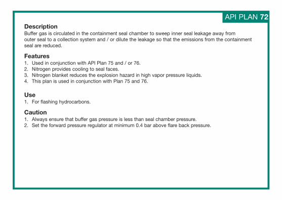
DescriptionBuffer gas is circulated in the containment seal chamber to sweep inner seal leakage away from outer seal to a collection system and / or dilute the leakage so that the emissions from the containmentseal are reduced.
Features1. Used in conjunction with API Plan 75 and / or 76.2. Nitrogen provides cooling to seal faces.3. Nitrogen blanket reduces the explosion hazard in high vapor pressure liquids.4. This plan is used in conjunction with Plan 75 and 76.
Use1. For flashing hydrocarbons.
Caution1. Always ensure that buffer gas pressure is less than seal chamber pressure.2. Set the forward pressure regulator at minimum 0.4 bar above flare back pressure.
API PLAN 72
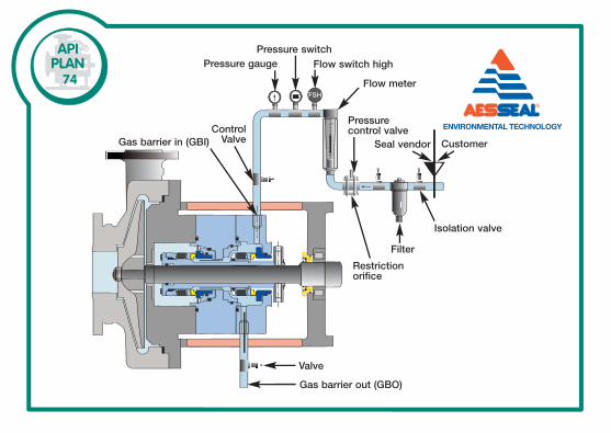
FSH
5
10
1
74Pressure gauge
Pressure switchFlow switch high
Flow meter
Pressurecontrol valve
Seal vendor Customer
Isolation valve
Filter
Restriction orifice
Valve
Gas barrier out (GBO)
Gas barrier in (GBI)Control
Valve
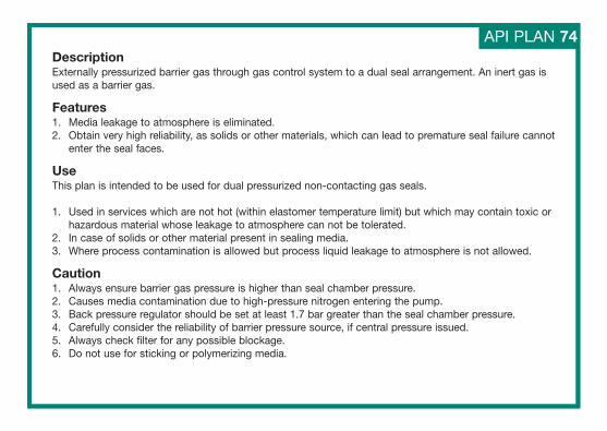
DescriptionExternally pressurized barrier gas through gas control system to a dual seal arrangement. An inert gas isused as a barrier gas.
Features1. Media leakage to atmosphere is eliminated.2. Obtain very high reliability, as solids or other materials, which can lead to premature seal failure cannot
enter the seal faces.
UseThis plan is intended to be used for dual pressurized non-contacting gas seals.
1. Used in services which are not hot (within elastomer temperature limit) but which may contain toxic orhazardous material whose leakage to atmosphere can not be tolerated.
2. In case of solids or other material present in sealing media.3. Where process contamination is allowed but process liquid leakage to atmosphere is not allowed.
Caution1. Always ensure barrier gas pressure is higher than seal chamber pressure.2. Causes media contamination due to high-pressure nitrogen entering the pump.3. Back pressure regulator should be set at least 1.7 bar greater than the seal chamber pressure.4. Carefully consider the reliability of barrier pressure source, if central pressure issued.5. Always check filter for any possible blockage.6. Do not use for sticking or polymerizing media.
API PLAN 74
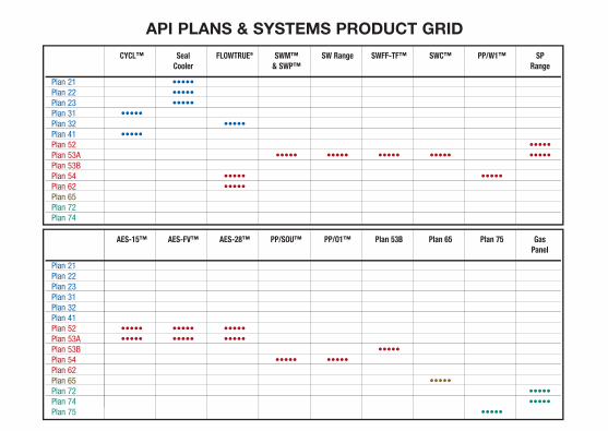
CYCL™ Seal FLOWTRUE® SWM™ SW Range SWFF-TF™ SWC™ PP/W1™ SP Cooler & SWP™ Range
Plan 21 •••••Plan 22 •••••Plan 23 •••••Plan 31 •••••Plan 32 •••••Plan 41 •••••Plan 52 •••••Plan 53A ••••• ••••• ••••• ••••• •••••Plan 53BPlan 54 ••••• •••••Plan 62 •••••Plan 65Plan 72Plan 74
AES-15™ AES-FV™ AES-28™ PP/SOU™ PP/O1™ Plan 53B Plan 65 Plan 75 GasPanel
Plan 21Plan 22Plan 23Plan 31Plan 32Plan 41Plan 52 ••••• ••••• •••••Plan 53A ••••• ••••• •••••Plan 53B •••••Plan 54 ••••• •••••Plan 62Plan 65 •••••Plan 72 •••••Plan 74 •••••Plan 75 •••••
API PLANS & SYSTEMS PRODUCT GRID
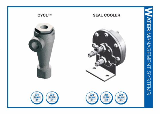
CYCL™
31 41
SEAL COOLER
21 2322
AT
ER
MA
NA
GE
ME
NT S
YS
TEM
SW
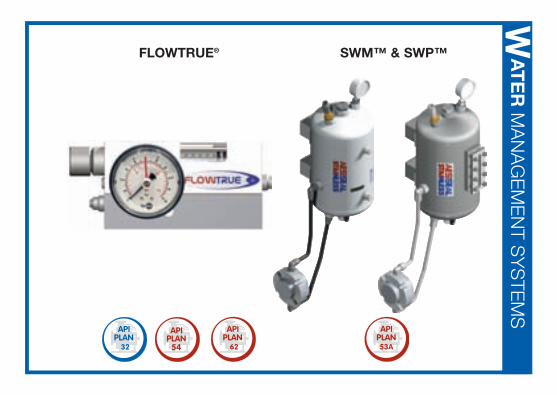
FLOWTRUE®
32 62
SWM™ & SWP™ AT
ER
MA
NA
GE
ME
NT S
YS
TEM
SW
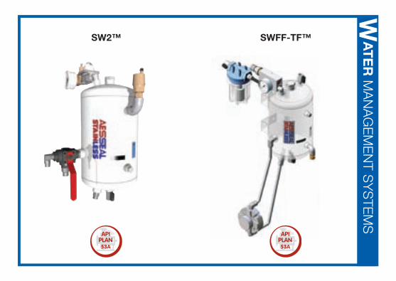
SW2™ AT
ER
MA
NA
GE
ME
NT S
YS
TEM
SW
SWFF-TF™
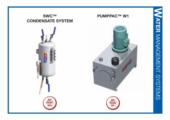
SWC™CONDENSATE SYSTEM
PUMPPAC™ W1 AT
ER
MA
NA
GE
ME
NT S
YS
TEM
SW
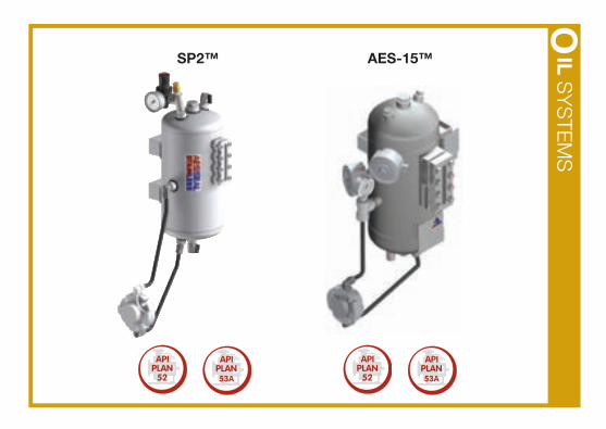
AES-15™SP2™ ILS
YS
TEM
SO
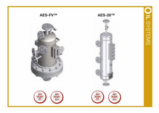
AES-FV™ AES-28™ ILS
YS
TEM
SO
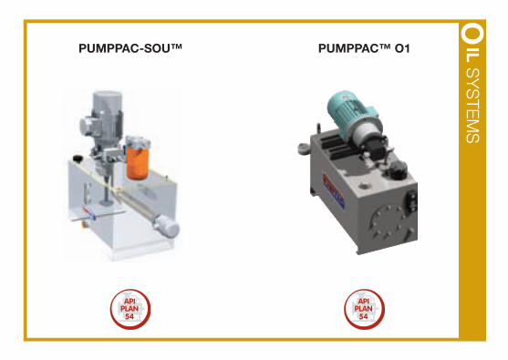
PUMPPAC™ O1PUMPPAC-SOU™ ILS
YS
TEM
S
O
IGH
EN
D S
YS
TEM
SH
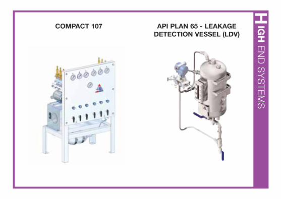
COMPACT 107 API PLAN 65 - LEAKAGEDETECTION VESSEL (LDV)
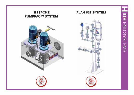
PLAN 53B SYSTEMBESPOKE PUMPPAC™ SYSTEM
IGH
EN
D S
YS
TEM
SH
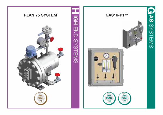
PLAN 75 SYSTEM
72 74
GAS16-P1™ AS
SY
STE
MS
G
IGH
EN
D S
YS
TEM
SH
www.aesseal.com
Our Purpose:
‘To give our customers such exceptional service that they need never consider alternative sources of supply.’
AESSEAL plc, Rotherham, UK Tel: +44 (0) 1709 369966 [email protected]
AESSEAL (MCK) Ltd, Lisburn, UK Tel: +44 (0) 2892 669966 [email protected]
AESSEAL Ireland Ltd, Co Cork, Eire Tel: +353 (0) 214 633477 [email protected]
AESSEAL Inc, Rockford, TN, USA Tel: +1 865 5 310192 [email protected]
AESSEAL ALAA, Dammam, Saudi Arabia Tel: +966 3 847 0033 [email protected]
AESSEAL Argentina SA, Buenos Aires, Argentina Tel: +54 11 4744 0022 [email protected]
AESSEAL Australia Pty Ltd, Seventeen Mile Rocks, Australia Tel: +61 7 32791 144 [email protected]
AESSEAL Benelux BV, Breda, Holland Tel: +31 (0) 76 564 9292 [email protected]
AESSEAL Brasil Ltda, São Paulo, Brazil Tel: +55 11 5891 5878 [email protected]
AESSEAL Canada Inc, Vancouver, Canada Tel: +1 604 535 7512 [email protected]
AESSEAL Chile SA, Providencia Santiago, Chile Tel: +56 2 2343022 [email protected]
AESSEAL China Ltd, Ningbo, China Tel: +86 (0) 574 8823 2888 [email protected]
AESSEAL Colombia SA, Bogota, Colombia Tel: +57 (1) 634 9095 [email protected]
AESSEAL Danmark, A/S, Køge, Denmark Tel: +45 56 64 14 00 [email protected]
AESSEAL Deutschland AG, Bad Orb, Germany Tel: +49 (0) 6052 918810 [email protected]
AESSEAL Deutschland GmbH, Kronau, Germany Tel: +49 (0) 7253 8090 [email protected]
AESSEAL France SARL, Nieppe, France Tel: +33 320 172850 [email protected]
AESSEAL India PVT, Ltd, Pune, India Tel: +91 2113 302222 [email protected]
AESSEAL Italia SRL, Gallarate, Italy Tel: +39 0331 799 952 [email protected]
AESSEAL Malaysia, SDN BHD, Selangor, Malaysia Tel: +603 806 21233 [email protected]
AESSEAL Mexico, S de RL de CV, Mexico City, Mexico Tel: +52 833 266 9551 [email protected]
AESSEAL Polska, SP ZO.O., Bielsko Biala, Poland Tel: +48 33 818 4135 [email protected]
AESSEAL Russia, Koroliov City, Moscow, Russia Tel: +7 495 777 4011 [email protected]
AESSEAL Pty Ltd, Durban, South Africa Tel: +27 (0) 31 903 5438 [email protected]
AESSEAL Ibérica SL, Tarragona, Spain Tel: +34 977 55 43 30 [email protected]
AESSEAL Turkiye, Istanbul, Turkey Tel: +90 (0) 216 304 0237 [email protected]
AESSEAL® Global Locations
AESSEAL® is a Registered Trademark of AESSEAL plc Copyright © 2009 AESSEAL plc Ref: L-UK/US-PIPINGPLAN-05 AES/DOC/IN 5080 06/09


![Shunting data Copying stuctures. Text fileDB tableDouble[]Gsl_vectorGsl_matrixApop_dat a Text fileCFF DB tableQQQQ Double[]CFF Gsl_vectorPPFCFF Gsl_matrixPPFVCF](https://img.pdfslide.net/doc/110x75/5513d7d25503466f748b4ffd/shunting-data-copying-stuctures-text-filedb-tabledoublegslvectorgslmatrixapopdat-a-text-filecff-db-tableqqqq-doublecff-gslvectorppfcff-gslmatrixppfvcf.jpg)