Embed Size (px)
Citation preview
ro-solutions.com
Instruction
APP pump instruction APP (W) 5.1-10.2
MAKING MODERN LIVING POSSIBLE
Instruction APP pump instruction APP (W) 5.1-10.2
2 180R9072 / 521B0747 / DKCFN.PI.010.D5.02 / 11.2014
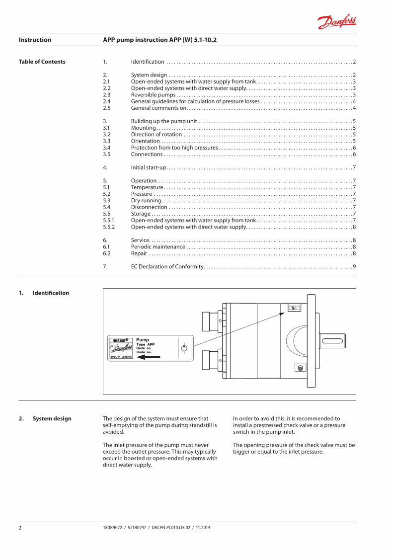
1. Identification
2. System design
Nessie® is a trademark of Danfoss A/S
180R
9072
521B0747 DKCFN.PI.010.D4.ML 12-2004
180R
9072
INSTRUCTIONSWater Pump
type APP 5.1/5.6/7.2/8.2/10.2
Contenu1. Identifi cation2. Conception du système3. Montage de la pompe4. Mise en route initiale5. Fonctionnement6. Service
Contenidos1. Identifi cación2. Diseño del sistema3. Montaje de la unidad de bombeo4. Arranque de la bomba5. Operación6. Servicio Técnico
1. Identifi cation
1. Identifi cación
2. Conception du système2.1 Systèmes ouverts avec réservoir d’eau2.2 Systèmes ouverts avec alimentation directe2.3 Pompes réversibles
La conception du système doit garantir que la pompe ne puisse se vider lorsque l’installation est à l’arrêtLa pression à l’entrée de la pompe ne peut jamais excéder la pression à la sortie. Ceci peut survenir lorsque la pompe est alimentée par une pompe de gavage ou dans des systèmes ouverts avec alimentation directe. Afi n d’éviter tout problème, il est recommandé d’installer un clapet anti-retour pré-taré en sortie de pompe ou un pressostat à l’entrée de la pompe.La pression d’ouverture du clapet anti-retour doit être supérieure ou égale à la pression mesurée à l’entrée de la pompe.
2. Diseño del sistemaLos sistemas pueden ser de dos tipos:2.1. Sistema abierto a presión atmosférica con suministro de agua de un
tanque.2.2. Sistema abierto a presión atmosférica con suministro directo de
agua.2.3. Problemas con bombas reversibles
El diseño del sistema debe asegurar que la bomba de agua no se vacíe cuando esté parada.
La presión de la entrada de agua a la bomba nunca debe de ser superior a la presión de salida. Esto puede ocurrir normalmente en sistemas con una bomba booster o en sistemas abiertos a presión atmosférica con un suministro directo de agua. Para evitar esto, se recomienda instalar una válvula antiretorno pretensionada o una válvula de seguridad entre la bomba y la válvula bypass. La presión de apertura de la válvula antiretorno debe ser mayor o igual a la presión de entrada del agua.
Contents1. Identifi cation2. System design3. Building up the pump unit4. Initial start up5. Operation6. Service
Inhalt1. Bezeichnung2. Systemaufbau3. Aufbau der Pumpeneinheit4. Erste Inbetriebnahme5. Betrieb6. Wartung
1. Identifi cation
1. Bezeichnung
2. System design2.1 Open-ended systems with water supply from a tank.2.2 Open-ended systems with direct water supply.2.3 Problems with reversing pumps
The design of the system must ensure that self-emptying of the pump during standstill is avoided.The inlet pressure of the pump must never exceed the outlet pressure. This may typically occur in boosted or open-ended systems with direct water supply. In order to avoid this, it is recommended to install a prestressed check valve or a pressure switch in the pump inlet.The opening pressure of the check valve must be bigger or equal to the inlet pressure.
2. Systemaufbau2.1 Off ene Systeme ohne Rückführung mit Versorgung aus einem Tank.2.2 Off ene Systeme ohne Rückführung, mit direkter Wasserversorgung.2.3 Umkehrpumpen
Der Systemaufbau muß sichern, daß sich die Pumpe im Stillstand nicht entleert.Der Druck am Pumpeneinlaß darf den Druck am Pumpenauslaß nicht übersteigen. Dies mag typisch in “boosted” oder off enen Systemen mit direkter Wasserversorgung auftreten. Um dies zu vermeiden, empfehlen wir die Montage eines vorgespann-ten Rückschlagventils oder eines Druckschalters in der Pumpeneinlass-Seite. Der Öff nungsdruck des Rückschlagventils muß den Einlaßdruck übersteigen oder diesem gleich sein.
The design of the system must ensure that self-emptying of the pump during standstill is avoided.
The inlet pressure of the pump must never exceed the outlet pressure. This may typically occur in boosted or open-ended systems with direct water supply.
In order to avoid this, it is recommended to install a prestressed check valve or a pressure switch in the pump inlet.
The opening pressure of the check valve must be bigger or equal to the inlet pressure.
1. Identification . . . . . . . . . . . . . . . . . . . . . . . . . . . . . . . . . . . . . . . . . . . . . . . . . . . . . . . . . . . . . . . . . . . . . . . . . . . 2
2. System design . . . . . . . . . . . . . . . . . . . . . . . . . . . . . . . . . . . . . . . . . . . . . . . . . . . . . . . . . . . . . . . . . . . . . . . . . . 22.1 Open-ended systems with water supply from tank. . . . . . . . . . . . . . . . . . . . . . . . . . . . . . . . . . . . . . . 32.2 Open-ended systems with direct water supply. . . . . . . . . . . . . . . . . . . . . . . . . . . . . . . . . . . . . . . . . . . 32.3 Reversible pumps . . . . . . . . . . . . . . . . . . . . . . . . . . . . . . . . . . . . . . . . . . . . . . . . . . . . . . . . . . . . . . . . . . . . . . . 32.4 General guidelines for calculation of pressure losses . . . . . . . . . . . . . . . . . . . . . . . . . . . . . . . . . . . . . 42.5 General comments on. . . . . . . . . . . . . . . . . . . . . . . . . . . . . . . . . . . . . . . . . . . . . . . . . . . . . . . . . . . . . . . . . . . 4
3. Building up the pump unit . . . . . . . . . . . . . . . . . . . . . . . . . . . . . . . . . . . . . . . . . . . . . . . . . . . . . . . . . . . . . . 53.1 Mounting . . . . . . . . . . . . . . . . . . . . . . . . . . . . . . . . . . . . . . . . . . . . . . . . . . . . . . . . . . . . . . . . . . . . . . . . . . . . . . . 53.2 Direction of rotation . . . . . . . . . . . . . . . . . . . . . . . . . . . . . . . . . . . . . . . . . . . . . . . . . . . . . . . . . . . . . . . . . . . . 53.3 Orientation . . . . . . . . . . . . . . . . . . . . . . . . . . . . . . . . . . . . . . . . . . . . . . . . . . . . . . . . . . . . . . . . . . . . . . . . . . . . . 53.4 Protection from too high pressures . . . . . . . . . . . . . . . . . . . . . . . . . . . . . . . . . . . . . . . . . . . . . . . . . . . . . . 63.5 Connections . . . . . . . . . . . . . . . . . . . . . . . . . . . . . . . . . . . . . . . . . . . . . . . . . . . . . . . . . . . . . . . . . . . . . . . . . . . . 6
4. Initial start-up. . . . . . . . . . . . . . . . . . . . . . . . . . . . . . . . . . . . . . . . . . . . . . . . . . . . . . . . . . . . . . . . . . . . . . . . . . . 7
5. Operation. . . . . . . . . . . . . . . . . . . . . . . . . . . . . . . . . . . . . . . . . . . . . . . . . . . . . . . . . . . . . . . . . . . . . . . . . . . . . . . 75.1 Temperature . . . . . . . . . . . . . . . . . . . . . . . . . . . . . . . . . . . . . . . . . . . . . . . . . . . . . . . . . . . . . . . . . . . . . . . . . . . . 75.2 Pressure . . . . . . . . . . . . . . . . . . . . . . . . . . . . . . . . . . . . . . . . . . . . . . . . . . . . . . . . . . . . . . . . . . . . . . . . . . . . . . . . 75.3 Dry running. . . . . . . . . . . . . . . . . . . . . . . . . . . . . . . . . . . . . . . . . . . . . . . . . . . . . . . . . . . . . . . . . . . . . . . . . . . . . 75.4 Disconnection . . . . . . . . . . . . . . . . . . . . . . . . . . . . . . . . . . . . . . . . . . . . . . . . . . . . . . . . . . . . . . . . . . . . . . . . . . 75.5 Storage . . . . . . . . . . . . . . . . . . . . . . . . . . . . . . . . . . . . . . . . . . . . . . . . . . . . . . . . . . . . . . . . . . . . . . . . . . . . . . . . . 75.5.1 Open-ended systems with water supply from tank. . . . . . . . . . . . . . . . . . . . . . . . . . . . . . . . . . . . . . . 75.5.2 Open-ended systems with direct water supply. . . . . . . . . . . . . . . . . . . . . . . . . . . . . . . . . . . . . . . . . . . 8
6. Service. . . . . . . . . . . . . . . . . . . . . . . . . . . . . . . . . . . . . . . . . . . . . . . . . . . . . . . . . . . . . . . . . . . . . . . . . . . . . . . . . . 86.1 Periodic maintenance . . . . . . . . . . . . . . . . . . . . . . . . . . . . . . . . . . . . . . . . . . . . . . . . . . . . . . . . . . . . . . . . . . . 86.2 Repair . . . . . . . . . . . . . . . . . . . . . . . . . . . . . . . . . . . . . . . . . . . . . . . . . . . . . . . . . . . . . . . . . . . . . . . . . . . . . . . . . . 8
7. EC Declaration of Conformity. . . . . . . . . . . . . . . . . . . . . . . . . . . . . . . . . . . . . . . . . . . . . . . . . . . . . . . . . . . . 9
Table of Contents
Instruction APP pump instruction APP (W) 5.1-10.2
3180R9072 / 521B0747 / DKCFN.PI.010.D5.02 / 11.2014
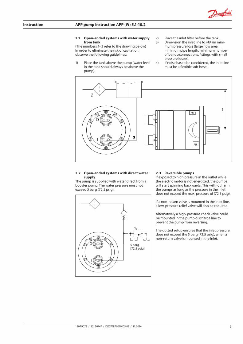
2.1 Open-ended systems with water supply from tank
(The numbers 1- 3 refer to the drawing below)In order to eliminate the risk of cavitation, observe the following guidelines:
1) Place the tank above the pump (water level in the tank should always be above the pump).
2) Place the inlet filter before the tank.3) Dimension the inlet line to obtain mini-
mum pressure loss (large flow area, minimum pipe length, minimum number of bends/connections, fittings with small pressure losses).
4) If noise has to be considered, the inlet line must be a flexible soft hose.
2 521B0747 DKCFN.PI.010.D3.ML
Re 2.1 Open-ended systems, water supply from tank(The numbers 1- 3 refer to the drawing below)In order to eliminate the risk of cavitation, observe the following guidelines:1) Place the tank above the pump (water level in the tank should
always be above the pump).2) Place the inlet fi lter before the tank.3) Dimension the inlet line to obtain minimum pressure loss (large
fl ow area, minimum pipe length, minimum number of bends/connections, fi ttings with small pressure losses).
4) If noise has to be considered, the inlet line must be a fl exible soft hose.
2.1 Off ene Systeme mit Wassertank(Die Nummern 1- 3 beziehen sich auf die unten abgebildete Zeichnung)Um das Risiko der Kavitation zu vermeiden, befolgen Sie folgendeRichtlinien:1) Den Tank über der Pumpe hoch anbringen (der Wasserstand im
Behälter sollte immer über Pumpenniveau sein).2) Das Zulauffi lter vor dem Behälter anbringen.3) Die Saugleitung im Hinblick auf minimalen Druckverlust
dimensionieren (großer Durchströmungsbereich, minimale Rohrlänge, minimale Anzahl von Winkelverschraubungen und Verschraubungen mit kleinem Druckverlust).
4) Falls Geräusch berücksichtigt werden muss, muss die Saugleitung ein fl exibler Schlauch sein.
Re 2.1 Systèmes ouverts avec réservoir d’eau(Les numéros 1- 3 se réfèrent au schéma repris ci-dessous)Pour éliminer tout risque de cavitation, observez les recommandations suivantes:1) Placer le réservoir au-dessus de la pompe (le niveau de l’eau dans le
réservoir devra toujours être plus haut que la pompe).2) Placer le fi ltre d’aspiration avant le réservoir.3) Dimensionner la conduite d’aspiration de manière à obtenir une
perte de charge minimale (grand diamètre, conduite courte, un minimum de courbes, raccords avec faibles pertes de charge).
Re 2.1. Sistema abierto a presión atmosférica, suministro de un tanque de agua.(Los números 1-3 se refi eren al gráfi co adjuntado)Para eliminar los riesgos de cavitación, observe las siguientes instrucciones:
1) Coloque el tanque por encima de la bomba (el nivel del agua del tanque siempre debe estar por encima del nivel de la bomba).
2) Coloque el fi ltro de entrada antes del tanque.3) Dimensione la línea de la entrada de manera que se obtenga la
menor pérdida de presión (una máxima sección de tubería, un mínimo de tuberías, un mínimo de recodos/conexiones, juntas con pocas pérdidas de presión).
4) Si hay que tener en cuenta el ruido, entonces la línea de entrada debe ser una manguera fl exible.
Re 2.2 Open-ended systems with direct water supply The pump is supplied with water direct from from a booster pump.The water pressure must not exceed 5 bar abs. (72,5 psi).
2.2 Off ene Systeme mit direkter WasserversorgungDie Pumpe wird direkt von einer Zwischenpumpe versorgt.Der Wasserdruck darf 5 bar abs. nicht übersteigen.
Re 2.2 Systèmes ouverts avec alimentation directeLa pompe est alimentée en eau par une pompe de gavage.La pression d’alimentation ne peut excéder 5 bar abs. (72.5 psi).
Re 2.2. Sistema abierto a presión atmosférica con suministro directo de agua.La bomba se abastece con agua procedente de una bomba “booster”. La presión del agua no debe exceder los 5 bar absolutos (72,5 psi).
2.2 Open-ended systems with direct water supply
The pump is supplied with water direct from a booster pump. The water pressure must not exceed 5 barg (72.5 psig).
2.3 Reversible pumpsIf exposed to high pressure in the outlet while the electric motor is not energized, the pumps will start spinning backwards. This will not harm the pumps as long as the pressure in the inlet does not exceed the max. pressure of (72.5 psig).
If a non-return valve is mounted in the inlet line, a low-pressure relief valve will also be required.
Alternatively a high-pressure check valve could be mounted in the pump discharge line to prevent the pump from reversing.
The dotted setup ensures that the inlet pressure does not exceed the 5 barg (72.5 psig), when a non-return valve is mounted in the inlet.
2 521B0747 DKCFN.PI.010.D3.ML
Re 2.1 Open-ended systems, water supply from tank(The numbers 1- 3 refer to the drawing below)In order to eliminate the risk of cavitation, observe the following guidelines:1) Place the tank above the pump (water level in the tank should
always be above the pump).2) Place the inlet fi lter before the tank.3) Dimension the inlet line to obtain minimum pressure loss (large
fl ow area, minimum pipe length, minimum number of bends/connections, fi ttings with small pressure losses).
4) If noise has to be considered, the inlet line must be a fl exible soft hose.
2.1 Off ene Systeme mit Wassertank(Die Nummern 1- 3 beziehen sich auf die unten abgebildete Zeichnung)Um das Risiko der Kavitation zu vermeiden, befolgen Sie folgendeRichtlinien:1) Den Tank über der Pumpe hoch anbringen (der Wasserstand im
Behälter sollte immer über Pumpenniveau sein).2) Das Zulauffi lter vor dem Behälter anbringen.3) Die Saugleitung im Hinblick auf minimalen Druckverlust
dimensionieren (großer Durchströmungsbereich, minimale Rohrlänge, minimale Anzahl von Winkelverschraubungen und Verschraubungen mit kleinem Druckverlust).
4) Falls Geräusch berücksichtigt werden muss, muss die Saugleitung ein fl exibler Schlauch sein.
Re 2.1 Systèmes ouverts avec réservoir d’eau(Les numéros 1- 3 se réfèrent au schéma repris ci-dessous)Pour éliminer tout risque de cavitation, observez les recommandations suivantes:1) Placer le réservoir au-dessus de la pompe (le niveau de l’eau dans le
réservoir devra toujours être plus haut que la pompe).2) Placer le fi ltre d’aspiration avant le réservoir.3) Dimensionner la conduite d’aspiration de manière à obtenir une
perte de charge minimale (grand diamètre, conduite courte, un minimum de courbes, raccords avec faibles pertes de charge).
Re 2.1. Sistema abierto a presión atmosférica, suministro de un tanque de agua.(Los números 1-3 se refi eren al gráfi co adjuntado)Para eliminar los riesgos de cavitación, observe las siguientes instrucciones:
1) Coloque el tanque por encima de la bomba (el nivel del agua del tanque siempre debe estar por encima del nivel de la bomba).
2) Coloque el fi ltro de entrada antes del tanque.3) Dimensione la línea de la entrada de manera que se obtenga la
menor pérdida de presión (una máxima sección de tubería, un mínimo de tuberías, un mínimo de recodos/conexiones, juntas con pocas pérdidas de presión).
4) Si hay que tener en cuenta el ruido, entonces la línea de entrada debe ser una manguera fl exible.
Re 2.2 Open-ended systems with direct water supply The pump is supplied with water direct from from a booster pump.The water pressure must not exceed 5 bar abs. (72,5 psi).
2.2 Off ene Systeme mit direkter WasserversorgungDie Pumpe wird direkt von einer Zwischenpumpe versorgt.Der Wasserdruck darf 5 bar abs. nicht übersteigen.
Re 2.2 Systèmes ouverts avec alimentation directeLa pompe est alimentée en eau par une pompe de gavage.La pression d’alimentation ne peut excéder 5 bar abs. (72.5 psi).
Re 2.2. Sistema abierto a presión atmosférica con suministro directo de agua.La bomba se abastece con agua procedente de una bomba “booster”. La presión del agua no debe exceder los 5 bar absolutos (72,5 psi).
5 barg[72.5 psig]
Instruction APP pump instruction APP (W) 5.1-10.2
4 180R9072 / 521B0747 / DKCFN.PI.010.D5.02 / 11.2014
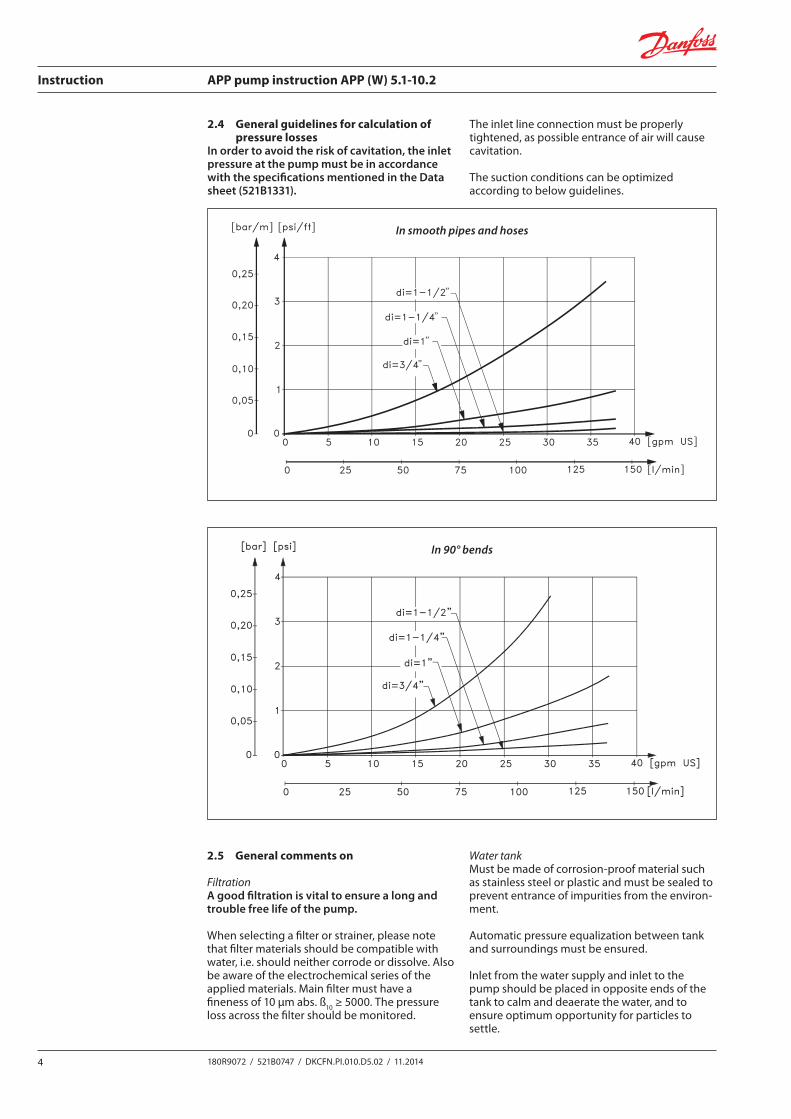
2.4 General guidelines for calculation of pressure losses
In order to avoid the risk of cavitation, the inlet pressure at the pump must be in accordance with the specifications mentioned in the Data sheet (521B1331).
The inlet line connection must be properly tightened, as possible entrance of air will cause cavitation.
The suction conditions can be optimized according to below guidelines.
4 521B0747 DKCFN.PI.010.D3.ML
2) In 90° bends 2) In 920° Winkeln
2) Dans les coudes 90°2) En codos de 90°
2.4 General comments on
FiltrationA good fi ltration is vital to ensure a long and trouble free life ofthe pump.When selecting a fi lter or strainer, please note that fi lter materialsshould be compatible with water, i.e. should neither corrode or dissolve.Also be aware of the electrochemical series of the applied materials.Main fi lter must have a fi neness of 10 µm abs.ß
10 >5000.
The pressure loss across the fi lter should be monitored.
Water tankMust be made of corrosion-proof material such as stainless steel orplastic and must be sealed to prevent entrance of impurities fromthe environment.Automatic pressure equalization between tank and surroundingsmust be ensured.Inlet from the water supply and inlet to the pump should be placed in opposite ends of the tank to calm and deaerate the water, and to ensure optimum opportunity for particles to settle.
2.4 Generelle Bemerkungen über
FiltrierungEine gute Filtrierung ist für eine lange Lebensdauer der Pumpeunerläßlich.Wenn Sie Filter oder Sieb wählen, beachten Sie bitte, daß das Filter-material Wasserverträglich sein muß, d.h. es darf weder korrodierennoch wasserlöslich sein. Beachte auch die elektrochemischenAusführungen der verwendeten Materialien.Das Hauptfi lter muß eine Feinheit von 10 µm Abs. ß
10 >5000
haben.Der Druckverlust über das Filter sollte überwacht werden.
WassertankMuß aus nichtrostendem Material wie rostfreiem Stahl oder Plastiksein. Um das Eindringen von Schmutzpartikeln aus den Umgebungenzu verhindern, muß der Behälter verschlossen sein.Der Druckausgleich zwischen Tank und Umgebung muß gewährleistetsein.Wasserversorgungseinlaß und die Saugleitung der Pumpe solltenmöglichst weit auseinander angebracht werden um das Wasser ineinem Zustand zu stillen und dadurch die best möglichen Voraus-setzungen für das Absetzen von Partikeln zu schaff en.
2.4 Généralités concernant
La fi ltrationUne bonne fi ltration est vitale pour garantir une longue durée de vie exempte de problème.Lors de la sélection d’un fi ltre ou d’une crépine, il est primordial que les matériaux utilisés soient compatibles avec l’eau (pas de corrosion ou d’érosion).Vérifi ez également les caractéristiques électrochimiques des matériaux.Le fi ltre principal doit présenter une fi nesse de 10 µm abs. ß
10 >5000.
La perte de charge au travers du fi ltre doit être contrôlée.
Le réservoir d’eauDoit être construit dans des matériaux à l’épreuve de la corrosion (acier inoxydable ou plastique) et étanche pour éviter l’intrusion d’impuretés en provenance de l’extérieur.Une égalisation automatique de la pression entre le réservoir et l’environnement doit être assurée.La conduite d’alimentation du réservoir et la conduite d’aspiration de la pompe seront placées chacune à une extrémité du réservoir afi n d’éviter les turbulences, de permettre une désaération du système et de permettre aux particules de se déposer au fonds du réservoir.
2.4. Comentarios generales sobre:
La fi ltraciónUna buena fi ltración de la bomba es vital para un funcionamiento sin problemas y una larga vida para la bomba.Para seleccionar un fi ltro o rejilla, por favor tenga en cuenta que los materiales del fi ltro deben ser compatibles con el agua, por ejemplo no se deben corroer ni disolver. También hay que tener en cuenta los potenciales electroquímicos de los materiales empleados.El fi ltro principal debe de tener un corte de 10 μm absolutas. β
10 /5000.
La pérdida de presión a través del fi ltro debe controlarse.
El tanque de aguaTiene que estar compuesto de materiales que no se corroan, como el acero inoxidable o el plástico, y tendrá que sellarse para prevenir la entrada de impurezas del medio.La presión entre el tanque y su medio debe regularse de manera automática.La entrada de agua del suministro de agua y la entrada a la bomba de agua se deben colocar en extremos opuestos del tanque para calmar y desoxigenar el agua, y para asegurarse de que las partículas se asienten.
In 90° bends
2.5 General comments on
FiltrationA good filtration is vital to ensure a long and trouble free life of the pump.
When selecting a filter or strainer, please note that filter materials should be compatible with water, i.e. should neither corrode or dissolve. Also be aware of the electrochemical series of the applied materials. Main filter must have a fineness of 10 μm abs. ß10 ≥ 5000. The pressure loss across the filter should be monitored.
Water tankMust be made of corrosion-proof material such as stainless steel or plastic and must be sealed to prevent entrance of impurities from the environ-ment.
Automatic pressure equalization between tank and surroundings must be ensured.
Inlet from the water supply and inlet to the pump should be placed in opposite ends of the tank to calm and deaerate the water, and to ensure optimum opportunity for particles to settle.
521B0747 DKCFN.PI.010.D3.ML 3
Re 2.3 Reversible pumpsIf exposed to high pressure in the outlet while the electric motor is not energized, the pumps will start spinning backwards. This will not harm the pumps as long as the pressure in the inlet does not exceed the max. pressure of 5 bar.If a non-return valve is mounted in the inlet line, a low-pressure relief valve will also be required.Alternatively a high-pressure check valve could be mounted in thepump discharge line to prevent the pump from reversing.The dotted setup ensures that the inlet pressure does not exceed the 5 bar abs., when a non-return valve is mounted in the inlet.
Re 2.3 UmkehrpumpenWenn Umkehrpumpen hohem Druck in der Auslassleitung ausgesetzt werden – während der Elektromotor nicht eingeschaltet ist – werden die Pumpen rückwärts larufen. Solange der Einlassdruck den max. Druck von 5 bar nicht übersteigt, werden die Pumpen vom Rückwärtslauf nicht beschädigt. Wenn ein Rückschlagventil in der Saugleitung montiert ist, ist ein Niederdruckbegrenzungsventil auch erforderlich.Als Alternative kann ein Hochdruck-Rückschlagventil im Auslass der Pumpe montiert werden, um Rückwärtslauf zu verhindern. Der mit den punktierten Linien gezeigte Aufbau sichert, dass der Ein-lassdruck die 5 bar abs nicht übersteigen wird, wenn ein Rückschlag-ventil im Einlass montiert ist.
Re 2.3 Pompes réversiblesEn cas de contre pression lors de l’arrêt du moteur électrique, la pompe commencera à tourner en sens inverse. Ceci n’endommagera pas la pompe pour autant que la pression à l’entrée de la pompe ne dépasse pas 5 bar.Si un clapet anti-retour est monté dans la conduite d’aspiration de la pompe, une soupape de sécurité basse pression devra également être montée.Solution alternative : le montage d’un clapet anti-retour dans la conduite haute pression (refoulement) évitera une rotation inverse de la pompe.Les recommandations précitées garantissent que la pression à l’entrée de la pompe ne dépassera pas 5 bar abs. lorsqu’un clapet anti-retour est monté dans la conduite d’aspiration de la pompe.
Re 2.3. Bomba reversibleSi se expone la salida de la bomba a alta presión mientras que el motor no esté en marcha las bombas empezarán a girar al revés. Esto no daña las bombas a no ser que la presión de la entrada supere los 5 bares. Si se pone una válvula antiretorno en la entrada, también se debe colocar una válvula de seguridad- Otra alternativa es poner una válvula antiretorno a la salida de la bomba para impedir que se invierta. La línea discontinua del gráfi co asegura que la presión no excedera los 5 bares cuando se monte una válvula en la entrada de la bomba.
General guidelines for calculation of pressure losses1) In smooth pipes and hoses
In order to avoid the risk of cavitation, the inlet pressure at the pump must be min. 0.9 bar (13 psi) abs.The inlet line connection must be properly tightened, as possibleentrance of air will cause cavitation.The suction conditions can be optimized according to below guidelineson page 4.
Generelle Richtlinien für die Berechnung von Druckverlusten.1) In geraden Rohren und Schläuchen
Um die Gefahr der Kavitation zu vermeiden muß der Druck amPumpeneinlaß min. 0,9 bar abs. sein.Die Montage der Einlaßleitung muß korrekt ausgeführt werden, daein evtl. Lufteintritt Kavitation verursachen wird.Die Saugverhältnisse können gemäß Richtlinien auf Seite 4 optimiertwerden.
Recommandations générales pour le calcul des pertes de charge.1) Dans les tubes lisses et les fl exibles
Afi n d’éviter tout risque de cavitation, la pression dans la conduite d’aspiration de la pompe sera de min. 0.9 bar (13 psi) abs.La conduite d’aspiration doit être étanche afi n d’éviter une possible entrée d’air qui causerait de la cavitation.Des conditions d’aspiration optimales peuvent être obtenues en suivant les recommandations décrites page 4.
Instrucciones generales para calcular las pérdidas de presión1) En tuberías lisas y mangueras
Para evitar el riesgo de cavitación, la presión de entrada en la bomba debe ser como mínimo de 0,9 bar (13 psi) abs.La línea de la conexión de la entrada debe estar sellada correctamente, ya que en caso de que entre aire se producirá cavitación. Las condiciones de succión pueden ser optimizadas siguiendo las instrucciones de la página 4.
In smooth pipes and hoses
Instruction APP pump instruction APP (W) 5.1-10.2
5180R9072 / 521B0747 / DKCFN.PI.010.D5.02 / 11.2014
3. Building up the pump unit
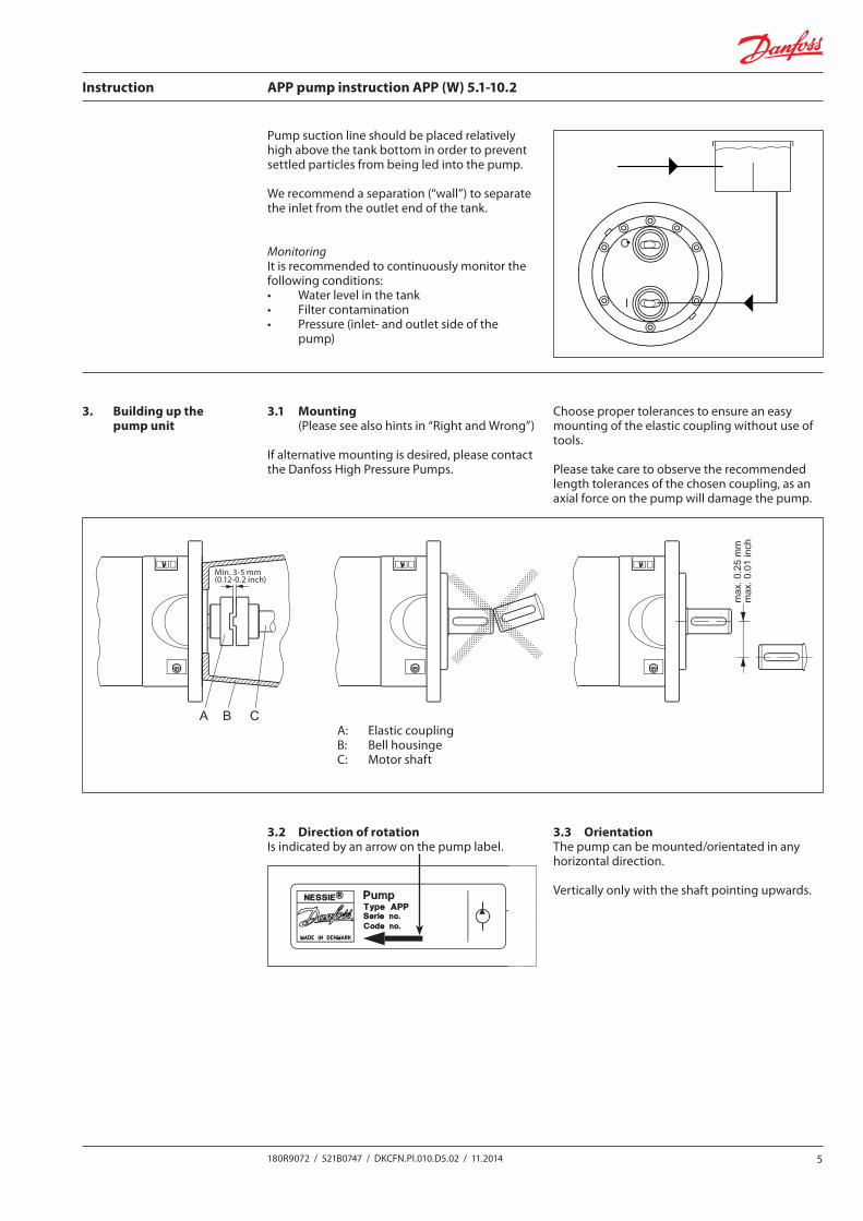
Pump suction line should be placed relatively high above the tank bottom in order to prevent settled particles from being led into the pump.
We recommend a separation (“wall”) to separate the inlet from the outlet end of the tank.
MonitoringIt is recommended to continuously monitor the following conditions:• Water level in the tank• Filter contamination• Pressure (inlet- and outlet side of the
pump)
521B0747 DKCFN.PI.010.D3.ML 5
Pump suction line should be placed relatively high above the tank bottom in order to prevent settled particles from being led into the pump.We recommend a separation (“wall”) to separate the inlet from the outlet end of the tank.
Die Zulaufl eitung sollte so hoch wie möglich über dem Tankbodenangebracht werden. Dies verhindert, daß bereits abgesetzte Partikelwieder aufgewirbelt und von der Pumpe angesaugt werden.Wir schlagen eine Trennung („Wand“) vor, die den Einlaß von derAuslaßseite des Tanks trennt.
MonitoringIt is recommended to continuously monitor the following conditions:• water level in the tank• fi lter contamination• pressure (inlet- and outlet side of the pump)
ÜberwachungWir empfehlen laufende Überwachung folgender Bedingungen:• Wasserstand im Tank• Verschmutzung des Filters• Druck (Ein- und Auslaßseite der Pumpe)
La conduite d’aspiration de la pompe sera placée relativement haut dans le réservoir pour éviter l’aspiration de particules gisant sur le fonds du réservoir.Nous recommandons le montage dans le réservoir d’une paroi afi n de séparer le coté alimentation en eau du coté aspiration de la pompe.
La línea de succión debe colocarse a una altura sufi ciente dentro del tanque para evitar que las partículas que se hayan asentado en el fondo no vayan a la bomba.Recomendamos una pared de separación entre la entrada y la salida de agua del tanque.
ContrôleIl est recommandé de contrôler en permanence les paramètres suivants:• Niveau de l’eau dans le réservoir• Niveau de contamination du fi ltre• Pression (entrée et sortie de pompe)
ControlRecomendamos controlar continuamente las siguientes condiciones:• el nivel del agua dentro del tanque• la contaminación del fi ltro• la presión (de entrada y salida de agua de la bomba)
3.1 Mounting (Please see also hints in “Right and Wrong”)
If alternative mounting is desired, please contact the Danfoss High Pressure Pumps.
Choose proper tolerances to ensure an easy mounting of the elastic coupling without use of tools.
Please take care to observe the recommended length tolerances of the chosen coupling, as an axial force on the pump will damage the pump.
3.2 Direction of rotationIs indicated by an arrow on the pump label.
3.3 OrientationThe pump can be mounted/orientated in any horizontal direction.
Vertically only with the shaft pointing upwards.
Nessie® is a trademark of Danfoss A/S
180R
9072
521B0747 DKCFN.PI.010.D4.ML 12-2004
180R
9072
INSTRUCTIONSWater Pump
type APP 5.1/5.6/7.2/8.2/10.2
Contenu1. Identifi cation2. Conception du système3. Montage de la pompe4. Mise en route initiale5. Fonctionnement6. Service
Contenidos1. Identifi cación2. Diseño del sistema3. Montaje de la unidad de bombeo4. Arranque de la bomba5. Operación6. Servicio Técnico
1. Identifi cation
1. Identifi cación
2. Conception du système2.1 Systèmes ouverts avec réservoir d’eau2.2 Systèmes ouverts avec alimentation directe2.3 Pompes réversibles
La conception du système doit garantir que la pompe ne puisse se vider lorsque l’installation est à l’arrêtLa pression à l’entrée de la pompe ne peut jamais excéder la pression à la sortie. Ceci peut survenir lorsque la pompe est alimentée par une pompe de gavage ou dans des systèmes ouverts avec alimentation directe. Afi n d’éviter tout problème, il est recommandé d’installer un clapet anti-retour pré-taré en sortie de pompe ou un pressostat à l’entrée de la pompe.La pression d’ouverture du clapet anti-retour doit être supérieure ou égale à la pression mesurée à l’entrée de la pompe.
2. Diseño del sistemaLos sistemas pueden ser de dos tipos:2.1. Sistema abierto a presión atmosférica con suministro de agua de un
tanque.2.2. Sistema abierto a presión atmosférica con suministro directo de
agua.2.3. Problemas con bombas reversibles
El diseño del sistema debe asegurar que la bomba de agua no se vacíe cuando esté parada.
La presión de la entrada de agua a la bomba nunca debe de ser superior a la presión de salida. Esto puede ocurrir normalmente en sistemas con una bomba booster o en sistemas abiertos a presión atmosférica con un suministro directo de agua. Para evitar esto, se recomienda instalar una válvula antiretorno pretensionada o una válvula de seguridad entre la bomba y la válvula bypass. La presión de apertura de la válvula antiretorno debe ser mayor o igual a la presión de entrada del agua.
Contents1. Identifi cation2. System design3. Building up the pump unit4. Initial start up5. Operation6. Service
Inhalt1. Bezeichnung2. Systemaufbau3. Aufbau der Pumpeneinheit4. Erste Inbetriebnahme5. Betrieb6. Wartung
1. Identifi cation
1. Bezeichnung
2. System design2.1 Open-ended systems with water supply from a tank.2.2 Open-ended systems with direct water supply.2.3 Problems with reversing pumps
The design of the system must ensure that self-emptying of the pump during standstill is avoided.The inlet pressure of the pump must never exceed the outlet pressure. This may typically occur in boosted or open-ended systems with direct water supply. In order to avoid this, it is recommended to install a prestressed check valve or a pressure switch in the pump inlet.The opening pressure of the check valve must be bigger or equal to the inlet pressure.
2. Systemaufbau2.1 Off ene Systeme ohne Rückführung mit Versorgung aus einem Tank.2.2 Off ene Systeme ohne Rückführung, mit direkter Wasserversorgung.2.3 Umkehrpumpen
Der Systemaufbau muß sichern, daß sich die Pumpe im Stillstand nicht entleert.Der Druck am Pumpeneinlaß darf den Druck am Pumpenauslaß nicht übersteigen. Dies mag typisch in “boosted” oder off enen Systemen mit direkter Wasserversorgung auftreten. Um dies zu vermeiden, empfehlen wir die Montage eines vorgespann-ten Rückschlagventils oder eines Druckschalters in der Pumpeneinlass-Seite. Der Öff nungsdruck des Rückschlagventils muß den Einlaßdruck übersteigen oder diesem gleich sein.
A: Elastic couplingB: Bell housingeC: Motor shaft
6 521B0747 DKCFN.PI.010.D3.ML
3. Building up the pump unit
3.1 Mounting (Please also see “Hints in Right and Wrong”)
A: Elastic coupling / Accouplement fl exibleB: Bell housing / LanterneC: Motor shaft / Arbre moteur
3. Aufbau der Pumpeneinheit
3.1 Montage (Siehe bitte auch „Hints in Right and Wrong“
A: Elastische KupplungB: Kupplungsgehäuse C: Motorwelle
If alternative mounting is desired, please contact the Danfoss Sales Organization.Choose proper tolerances to ensure an easy mounting of the elastic coupling without use of tools.Please take care to observe the recommended length tolerances of the chosen coupling, as an axial force on the pump will damage the pump.
Wünschen Sie eine alternative Montage, fragen Sie bitte Ihre Danfoss Verkaufsorganisation.Wählen Sie angemessene Toleranzen, um eine einfache Montage der elastischen Kupplung ohne Einsatz von Werkzeugen zu sichern.Beachten Sie bitte, daß die empfohlene Längentoleranz eingehalten wird, da eine Axialkraft auf die Pumpe schädlich für die Pumpe sein kann.
3.2 Direction of rotationIs indicated by means of an arrow at the inlet side of the pump.
3.2 DrehrichtungWird durch einen Pfeil seitlich der Einlaßseite der Pumpe angezeigt.
3.3 OrientationThe pump can be mounted/orientated in any horizontal direction.Vertically only with the shaft pointing upwards.
3.3 EinbaulageDie Pumpe kann willkürlich horizontal eingebaut werden.Vertikal aber nur mit der Welle nach oben.
3. Montage de la pompe
3.1 Montage (Voir également “Correct et incorrect”)
A: Accouplement fl exibleB: LanterneC: Arbre moteur
3. Montaje de la unidad de bombeo
3.1. Montaje (Ver sección sobre “Pistas sobre posible fallos”)
A: Acoplamiento ElásticoB: CampanaC: Eje del Motor
Si vous désirez un autre type de montage, contactez l’organisation commerciale de Danfoss.Choisissez des tolérances correctes pour faciliter le montage sans outils de l’accouplement fl exible.Concernant la longueur de l’accouplement, respectez les tolérances recommandées car toute charge axiale endommagera la pompe.
Para otro tipo de montaje contacte con el Departamento de Ventas de Danfoss.Escoger una tolerancia apropiada para facilitar el montaje del acoplamiento elástico sin el uso de herramientas. Por favor, mantengan las longitudes recomendadas de las tolerancias de los acoplamientos que hayan escogido; de esta manera se evitará una fuerza axial sobre el eje de la bomba que la podría dañar.
3.2 Sens de rotationEst indiqué par une fl èche située sur le coté aspiration de la pompe.
3.2 Dirección de rotaciónEstá indicada con una fl echa en un costado de la bomba.
3.3 OrientationLa pompe peut être orientée/montée horizontalement dans toutes les directions.En cas de montage vertical, l’arbre devra toujours être dirigé vers le haut.
3.3 OrientaciónLa bomba se puede montar u orientar en cualquier dirección horizontal. Solamente se puede montar de manera vertical con el eje mirando hacia arriba.
Min. 3-5 mm (0.12-0.2 inch)
Instruction APP pump instruction APP (W) 5.1-10.2
6 180R9072 / 521B0747 / DKCFN.PI.010.D5.02 / 11.2014
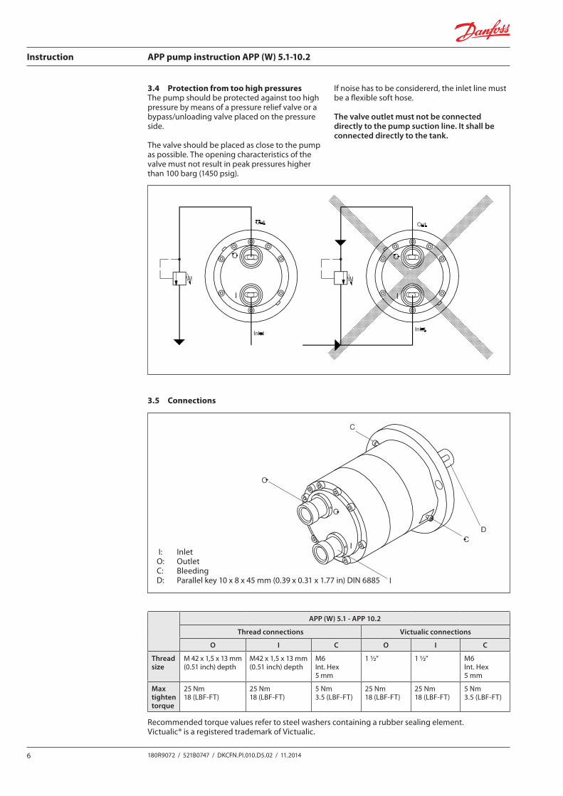
3.4 Protection from too high pressuresThe pump should be protected against too high pressure by means of a pressure relief valve or a bypass/unloading valve placed on the pressure side.
The valve should be placed as close to the pump as possible. The opening characteristics of the valve must not result in peak pressures higher than 100 barg (1450 psig).
If noise has to be considererd, the inlet line must be a flexible soft hose.
The valve outlet must not be connected directly to the pump suction line. It shall be connected directly to the tank.
521B0747 DKCFN.PI.010.D3.ML 7
3.4 Protection from too high pressuresThe pump should be protected against too high pressure by meansof a pressure relief valve or a bypass/unloading valve placed on thepressure side.The valve should be placed as close to the pump as possible.The opening characteristics of the valve must not result in peakpressures higher than 100 bar (1450 psi).If noise has to be considererd, the inlet line must be a fl exible softhose.The valve outlet must not be connected directly to the pump suction line. It shall be connected directly to the tank.
3.4 ÜberdruckabsicherungDie Pumpe sollte mit einem Überdruckventil oder einem Druckent-lastungsventil auf der Druckseite gegen zu hohen Druck abgesichert sein.Das Ventil sollte so nah wie möglich an der Pumpe montiert werden.Die Öff nungscharakteristik des Ventils darf keine Höchstwerte über100 bar zulassen.Falls Geräusch berücksichtigt werden muss, muss die Saugleitungein fl exibler Schlauch sein.Der Ventilauslaß darf nicht direkt mit der Pumpesaugleitung, sondern direkt mit dem Tank verbunden werden.
3.5 ConnectionsI : InletO: OutletC : BleedingD : Parallel key 5 × 5 × 20, DIN 6885
3.5 AnschlüsseI : EinlassT: AuslassC: EntlüftungD: Paßfeder 5 × 5 × 20, DIN 68853
3.4 Protection contre des pressions trop élevéesLa pompe devra être protégées contre des pressions trop élevées à l’aide d’une soupape de sécurité ou d’une vanne de by-pass/décharge placée sur le coté refoulement de la pompe.La vanne sera placée aussi près que possible de la pompe.Les caractéristiques d’ouverture de la vanne doivent permettre d’éviter des pointes de pression supérieures à 100 bar (1450 psi).Au cas où le niveau sonore s’avérerait être un point critique, il est recommandé d’utiliser un fl exible pour la conduite d’aspiration.La décharge de la vanne ne peut être raccordée à la conduite d’aspiration de la pompe. Elle sera raccordée directement au réservoir.
3.4 Protección contra las altas presionesLa bomba se debe proteger de las altas presiones por medio de una válvula reguladora de presión o por medio de una válvula bypass colocada en el lado de alta presión.La válvula se debe colocar lo más cerca posible a la bomba.En la apertura de la válvula no deben superarse los 100 bares (1450 psi).Si el ruido es de consideración, la línea de entrada debe ser una manguera fl exible.La salida de la válvula no debe conectarse directamente con la línea de succión de la bomba. Se debe conectar directamente con el tanque.
3.5 RaccordementI : AspirationO : Pression (décharge)C : PurgeD : Clavette 5 × 5 × 20, DIN 6885
3.5 ConexionesI: EntradaO: SalidaC: SangradoD: Llave paralela 5 × 5 × 20, DIN 6885
3.5 Connections
521B0747 DKCFN.PI.010.D3.ML 7
3.4 Protection from too high pressuresThe pump should be protected against too high pressure by meansof a pressure relief valve or a bypass/unloading valve placed on thepressure side.The valve should be placed as close to the pump as possible.The opening characteristics of the valve must not result in peakpressures higher than 100 bar (1450 psi).If noise has to be considererd, the inlet line must be a fl exible softhose.The valve outlet must not be connected directly to the pump suction line. It shall be connected directly to the tank.
3.4 ÜberdruckabsicherungDie Pumpe sollte mit einem Überdruckventil oder einem Druckent-lastungsventil auf der Druckseite gegen zu hohen Druck abgesichert sein.Das Ventil sollte so nah wie möglich an der Pumpe montiert werden.Die Öff nungscharakteristik des Ventils darf keine Höchstwerte über100 bar zulassen.Falls Geräusch berücksichtigt werden muss, muss die Saugleitungein fl exibler Schlauch sein.Der Ventilauslaß darf nicht direkt mit der Pumpesaugleitung, sondern direkt mit dem Tank verbunden werden.
3.5 ConnectionsI : InletO: OutletC : BleedingD : Parallel key 5 × 5 × 20, DIN 6885
3.5 AnschlüsseI : EinlassT: AuslassC: EntlüftungD: Paßfeder 5 × 5 × 20, DIN 68853
3.4 Protection contre des pressions trop élevéesLa pompe devra être protégées contre des pressions trop élevées à l’aide d’une soupape de sécurité ou d’une vanne de by-pass/décharge placée sur le coté refoulement de la pompe.La vanne sera placée aussi près que possible de la pompe.Les caractéristiques d’ouverture de la vanne doivent permettre d’éviter des pointes de pression supérieures à 100 bar (1450 psi).Au cas où le niveau sonore s’avérerait être un point critique, il est recommandé d’utiliser un fl exible pour la conduite d’aspiration.La décharge de la vanne ne peut être raccordée à la conduite d’aspiration de la pompe. Elle sera raccordée directement au réservoir.
3.4 Protección contra las altas presionesLa bomba se debe proteger de las altas presiones por medio de una válvula reguladora de presión o por medio de una válvula bypass colocada en el lado de alta presión.La válvula se debe colocar lo más cerca posible a la bomba.En la apertura de la válvula no deben superarse los 100 bares (1450 psi).Si el ruido es de consideración, la línea de entrada debe ser una manguera fl exible.La salida de la válvula no debe conectarse directamente con la línea de succión de la bomba. Se debe conectar directamente con el tanque.
3.5 RaccordementI : AspirationO : Pression (décharge)C : PurgeD : Clavette 5 × 5 × 20, DIN 6885
3.5 ConexionesI: EntradaO: SalidaC: SangradoD: Llave paralela 5 × 5 × 20, DIN 6885
APP (W) 5.1 - APP 10.2
Thread connections Victualic connections
O I C O I C
Thread size
M 42 x 1,5 x 13 mm (0.51 inch) depth
M42 x 1,5 x 13 mm (0.51 inch) depth
M6 Int. Hex 5 mm
1 ½“ 1 ½“ M6 Int. Hex 5 mm
Max tighten torque
25 Nm18 (LBF-FT)
25 Nm18 (LBF-FT)
5 Nm3.5 (LBF-FT)
25 Nm18 (LBF-FT)
25 Nm18 (LBF-FT)
5 Nm3.5 (LBF-FT)
Recommended torque values refer to steel washers containing a rubber sealing element.Victualic® is a registered trademark of Victualic.
I: InletO: OutletC: BleedingD: Parallel key 10 x 8 x 45 mm (0.39 x 0.31 x 1.77 in) DIN 6885
Instruction APP pump instruction APP (W) 5.1-10.2
7180R9072 / 521B0747 / DKCFN.PI.010.D5.02 / 11.2014
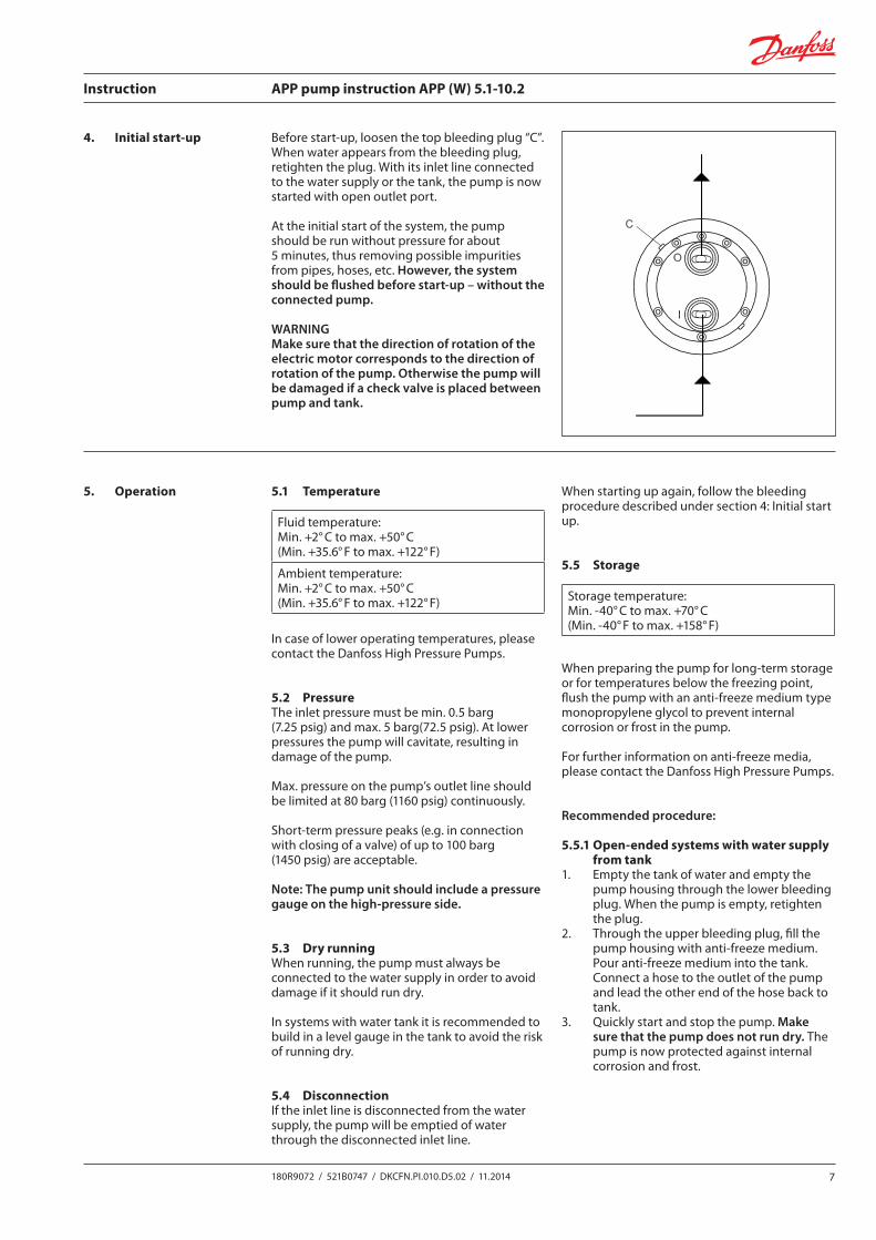
Before start-up, loosen the top bleeding plug “C”. When water appears from the bleeding plug, retighten the plug. With its inlet line connected to the water supply or the tank, the pump is now started with open outlet port.
At the initial start of the system, the pump should be run without pressure for about 5 minutes, thus removing possible impurities from pipes, hoses, etc. However, the system should be flushed before start-up – without the connected pump.
WARNINGMake sure that the direction of rotation of the electric motor corresponds to the direction of rotation of the pump. Otherwise the pump will be damaged if a check valve is placed between pump and tank.
4. Initial start-up
521B0747 DKCFN.PI.010.D3.ML 9
4. Initial start-up
Before start-up, loosen the top bleeding plug “C”. When water appears from the bleeding plug, retighten the plug. With its inlet line connected to the water supply or the tank, the pump is now started with open outlet port.At the initial start of the system, the pump should be run without pressure for about 5 minutes, thus removing possible impurities from pipes, hoses, etc. However, the system should be fl ushed before start-up However, the system should be fl ushed before start-up – without the connected pump– without the connected pump.
Warning:Make sure that the direction of rotation of the electric motor corresponds to the direction of rotation of the pump. Otherwise the pump will be damaged if a check valve is placed between pump and tank.
Note: The pumps are preserved with antifreeze Dowcal N.
4. Erste Inbetriebnahme
Vor der Inbetriebnahme, lösen Sie die obere Entlüftungsschraube “C”.Wenn Wasser aus der Entlüftungsschraube austritt, diese erneutanziehen. Die Pumpe – die Einlaßleitung zur Wasserversorgung oderzum Tank angeschlossen – wird jetzt mit off enem Auslaßanschluß(Druckseite) angelassen.Bei der ersten Inbetriebnahme sollte die Pumpe für etwa 5 Minutendrucklos laufen, um Schmutzpartikel aus Rohren, Schläuchen usw.zu entfernen. Jedoch sollte das System vor der ersten Inbetriebnahme Jedoch sollte das System vor der ersten Inbetriebnahme – ohne die angeschlossene Pumpe - durchgespült werden.– ohne die angeschlossene Pumpe - durchgespült werden.
Warnung:Beachten Sie, daß die Drehrichtung vom Elektromotor mit der Dreh-richtung der Pumpe übereinstimmt, da anderenfalls die Pumpe zerstört wird.
Bitte bemerken Sie: Die Pumpen werden mit Frostschutzmittel Dowcal N konserviert.
4. Mise en route initiale
Avant la mise en route, desserrer le bouchon de purge supérieur “C”. Lorsque l’eau apparaît, resserrer le bouchon.Avec la conduite d’aspiration raccordée à l’arrivée d’eau ou au réservoir rempli d’eau, la pompe sera démarrée avec la conduite de refoulement (haute pression) ouverte.Lors du démarrage initial, la pompe fonctionnera environ 5 minutes sans pression afi n d’évacuer de possible impuretés des tubes, fl exibles, etc. Le système sera toujours rincé avant la mise en route sans que la pompe Le système sera toujours rincé avant la mise en route sans que la pompe ne soit raccordée.
Attention:Vérifi ez que le sens de rotation du moteur électrique corresponde à celui de la pompe. Dans le cas contraire, la pompe sera endommagée si un clapet anti-retour est installé entre la pompe et le réservoir.
Note : Les pompes sont protégées par de l’antigel Dowcal N.
4. Arranque Inicial
Antes de arrancar, afl oje el tapón de sangrado C. Cuando aparezca agua, enrosque el tapón. Con esta línea de entrada conectada al suministro de agua o al tanque de agua, ahora se puede poner en funcionamiento la bomba de agua con un puerto de salida abierto.
La primera vez que ponga en funcionamiento el sistema, la bomba debe funcionar sin presión durante unos 5 minutos para así eliminar las impu-rezas que pueda haber en las tuberías, mangueras, etc. Sin embargo, el Sin embargo, el sistema deberá de ser enjuagado (fl ushed) antes del arranque inicial sin sistema deberá de ser enjuagado (fl ushed) antes del arranque inicial sin conectar la bomba.
Advertencia: Asegúrese de que la dirección de la rotación del motor eléctrico corres-ponda a la dirección de la rotación de la bomba. Si no, la bomba puede dañarse si se coloca una válvula antiretorno entre la bomba y el tanque.
Nota: Las bombas se almacenan con el anticongelante Doweal N.
5. Operation 5.1 Temperature
Fluid temperature: Min. +2° C to max. +50° C (Min. +35.6° F to max. +122° F)
Ambient temperature: Min. +2° C to max. +50° C (Min. +35.6° F to max. +122° F)
In case of lower operating temperatures, please contact the Danfoss High Pressure Pumps.
5.2 PressureThe inlet pressure must be min. 0.5 barg (7.25 psig) and max. 5 barg(72.5 psig). At lower pressures the pump will cavitate, resulting in damage of the pump.
Max. pressure on the pump’s outlet line should be limited at 80 barg (1160 psig) continuously.
Short-term pressure peaks (e.g. in connection with closing of a valve) of up to 100 barg (1450 psig) are acceptable.
Note: The pump unit should include a pressure gauge on the high-pressure side.
5.3 Dry runningWhen running, the pump must always be connected to the water supply in order to avoid damage if it should run dry.
In systems with water tank it is recommended to build in a level gauge in the tank to avoid the risk of running dry.
5.4 DisconnectionIf the inlet line is disconnected from the water supply, the pump will be emptied of water through the disconnected inlet line.
When starting up again, follow the bleeding procedure described under section 4: Initial start up.
5.5 Storage
When preparing the pump for long-term storage or for temperatures below the freezing point, flush the pump with an anti-freeze medium type monopropylene glycol to prevent internal corrosion or frost in the pump.
For further information on anti-freeze media, please contact the Danfoss High Pressure Pumps.
Recommended procedure:
5.5.1 Open-ended systems with water supply from tank
1. Empty the tank of water and empty the pump housing through the lower bleeding plug. When the pump is empty, retighten the plug.
2. Through the upper bleeding plug, fill the pump housing with anti-freeze medium. Pour anti-freeze medium into the tank. Connect a hose to the outlet of the pump and lead the other end of the hose back to tank.
3. Quickly start and stop the pump. Make sure that the pump does not run dry. The pump is now protected against internal corrosion and frost.
Storage temperature: Min. -40° C to max. +70° C(Min. -40° F to max. +158° F)
Instruction APP pump instruction APP (W) 5.1-10.2
8 180R9072 / 521B0747 / DKCFN.PI.010.D5.02 / 11.2014
5.5.2 Open-ended systems with direct water supply
1. Disconnect the water supply to the pump.2. Through the lower bleeding plug, empty
the pump housing of water and close it again.
3. Connect the pump to a tank of e.g. 25 litre/ 6 gal. of anti-freeze additive. Connect a
hose to the inlet port of the pump and via another hose return the flow from the outlet port to the tank with anti-freeze additives.
4. Quickly start and stop the pump. Make sure that the pump does not run dry. The pump is now protected against internal corrosion and frost.
6.1 Periodic maintenanceThe APP (W) pump is designed so that lubrica-tion follows from the water itself and there is thus no oil in the pump.
The pump requires no periodic replacements of seals and valve parts.
6.2 RepairIn case of irregular function in the pump, please contact the Danfoss High Pressure Pumps.
6. Service
9180R9072 / 521B0747 / DKCFN.PI.010.D5.02 / 11.2014
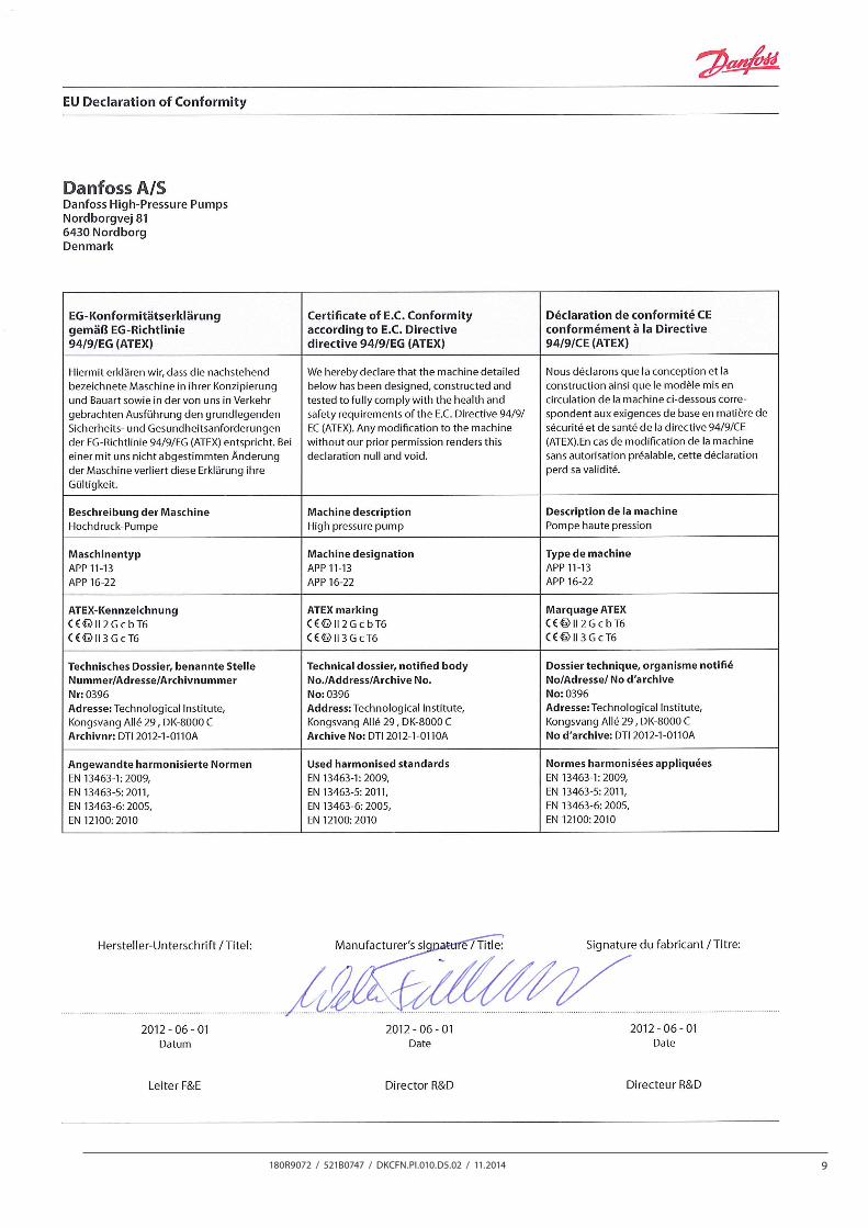
7. EC Declaration of Conformity
Instruction APP pump instruction APP (W) 5.1-10.2
10 180R9072 / 521B0747 / DKCFN.PI.010.D5.02 / 11.2014
Danfoss can accept no responsibility for possible errors in catalogues, brochures and other printed material. Danfoss reserves the right to alter its products without notice. This also applies to products already on order provided that such alterations can be made without subsequential changes being necessary in specifications already agreed.All trademarks in this material are property of the respective companies. Danfoss and the Danfoss logotype are trademarks of Danfoss A/S. All rights reserved.
Danfoss A/SHigh Pressure PumpsDK-6430 NordborgDenmark