Embed Size (px)
Citation preview
J. clin. Path. (1955), 8, 144.
AN APPARATUS FOR PAPER ELECTROPHORESISBY
G. T. FRANGLEN, N. H. MARTIN, AND J. D. TREHERNEFrom the Department of Chemical Pathology, St. George's Hospital Medical School, and the Physics Department,
St. George's Hospital, London
(RECEIVED FOR PUBLICATION FEBRUARY 17, 1955)
The apparent simplicity of filter paper electro-phoresis has led to its use in the analysis of a widerange of mixtures of clinical and biological impor-tance (see review by Martin and Franglen, 1954).The great interest in this technique has resulted inthe publication of numerous papers on the designand construction of paper electrophoresis cells.During the past five years the writers have gatheredpractical experience of many of these instruments,and of the quality and reproducibility of theseparations that can be obtained with them. As aresult, a cell has been designed for high-qualityelectrophoretic separation of mixtures on filterpaper; this apparatus is described in this paper.This cell has been in use for more than a year, andclose on a thousand different analyses have beencarried out successfully on it, reproducibility beingof a consistently high order. The prototype wasdemonstrated at a meeting of the Society ofChemical Industry in 1954 (Franglen and Martin,1954).
In designing such an apparatus, the following threerequirements were considered to be essential: (1)Stable electrical conditions; (2) stable conditionsin and about the paper on which electrophoresistakes place (" working strip"); (3) a means ofapplying the material to be analysed to the workingstrip with the minimum disturbance of conditionsin the cell.To satisfy the first requirement, it was found that,
while it was easy to deliver a constant voltage bysuitable stabilizers to all the electrophoretic cellstested, steady electrical conditions could not bemaintained across the working strip when simplecarbon electrodes were used. This is due to the factthat these electrodes readily polarize under theconditions normally used for paper electrophoresis.Moreover, in many buffers, carbon electrodes werefound to disintegrate. Reversible silver-silverchloride-potassium chloride electrodes were used inthe apparatus described here, and were found to beperfectly satisfactory. The surface area of eachelectrode is about 60 cm.2 when silver wire of 0.1
cm. diameter is used; this area is ample to dealwith any current normally required. Moreover,the electrode carriers are designed so that otherductile metals, such as copper or platinum, can beused.To satisfy the second requirement, it is necessary
to ensure that (1) the buffer solution is evenlydistributed over the whole working area of the paper;(2) the working strip is maintained at a controlledeven tension; (3) changes oftemperature and ofwatervapour content of the atmosphere about the workingstrip are reduced to a minimum. As pointed outby Durrum (1950), the inverted V electrophoresisapparatus cannot maintain an even distributionof buffer solution over the working strip. At thesame time, the type of cell which involves continuousor intermittent support of a horizontal workingstrip must introduce side-effects difficult to controland to compute although the horizontal positionof the working strip does result in even distributionof buffer solution over the working area. It wasdecided, therefore, to use a cell in which the paperwas horizontal, but supported only at the ends whereelectrophoretic separation should not take place.In designing such an apparatus, it was essential toeliminate any sag that might occur in the workingstrip as it became saturated with buffer solution.This has been achieved by stretching the paperbetween two glass rods, the position of which canbe adjusted to take up any sag and to maintain aneven tension in the paper. Just above and below theworking strip are two surfaces from which con-tinuous evaporation of buffer solution may takeplace. This rapidly and completely saturates theatmosphere immediately around the working stripwith water vapour, and results in the maintenanceof a steady temperature in the apparatus. Measure-ments with thermocouples set in the working stripshowed that the rise in temperature in an overnightrun was no more than 0.30° C., even when potentialdifferences as great as 10 V./cm. were applied to thepaper. The apparatus takes a working strip 20 cm.in width on which six or more analyses can be carried
on Decem
ber 9, 2021 by guest. Protected by copyright.
http://jcp.bmj.com
/J C
lin Pathol: first published as 10.1136/jcp.8.2.144 on 1 M
ay 1955. Dow
nloaded from
FILTER PAPER ELECTROPHORESIS
out simultaneously. The analysis is normally carriedout in air, but, when necessary, it may be conductedin an atmosphere of nitrogen or any other gas.To safi*the third requirement, the material to be
analysed is laid on the paper through a smallentrance port in the lid of the apparatus. Thecomparative smallness of this opening together withthe use of equilibrating devices within the apparatusresult in very little disturbance of internal conditionsof the cell during the application. After the materialis laid on, the port is sealed by an air-tight lid.
Technical SectionGeneral Description of Apparatus.-A general view
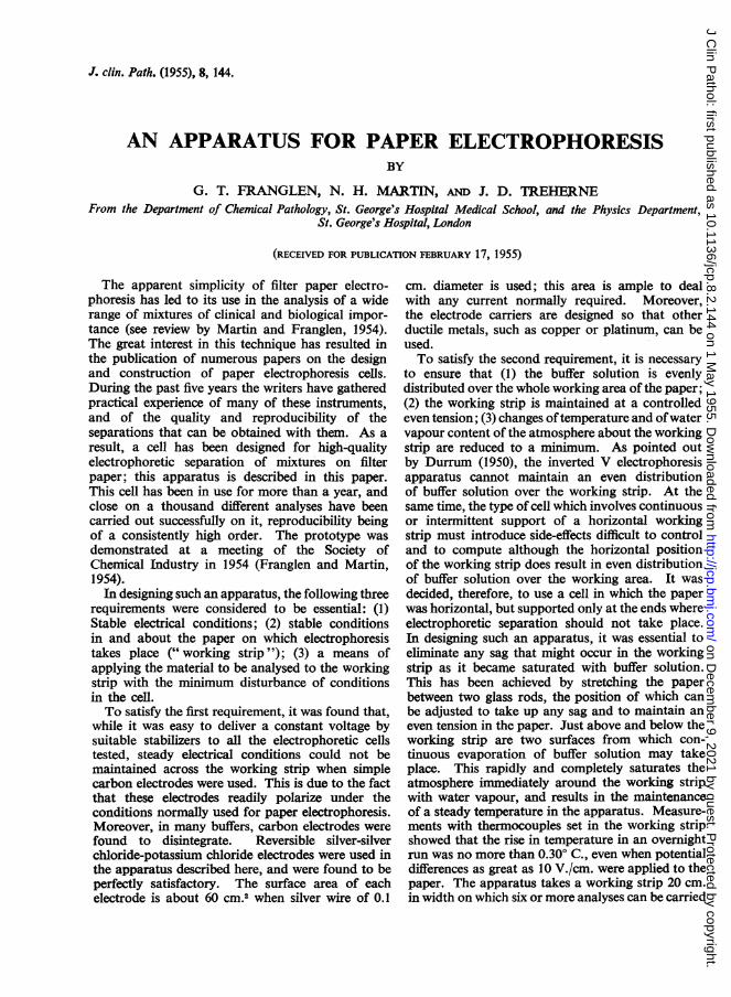
of the apparatus is shown in Fig. 1, and details of internalfittings are shown in Fig. 2. In its present form, theapparatus is a rectangular box measuring 28 x 30 x 8cm. made of thick perspex. To ensure complete air-tightness, a recessed rubber washer of square section0.6 cm. thick (A, Figs. 1 and 2) is set into the rim of thebox, and on to this a perspex lid is clamped by hingedbolts (B, Fig. 2). Electrode vessels (C, Figs. 1 and 2) arecemented on to the outside of the main box, and are
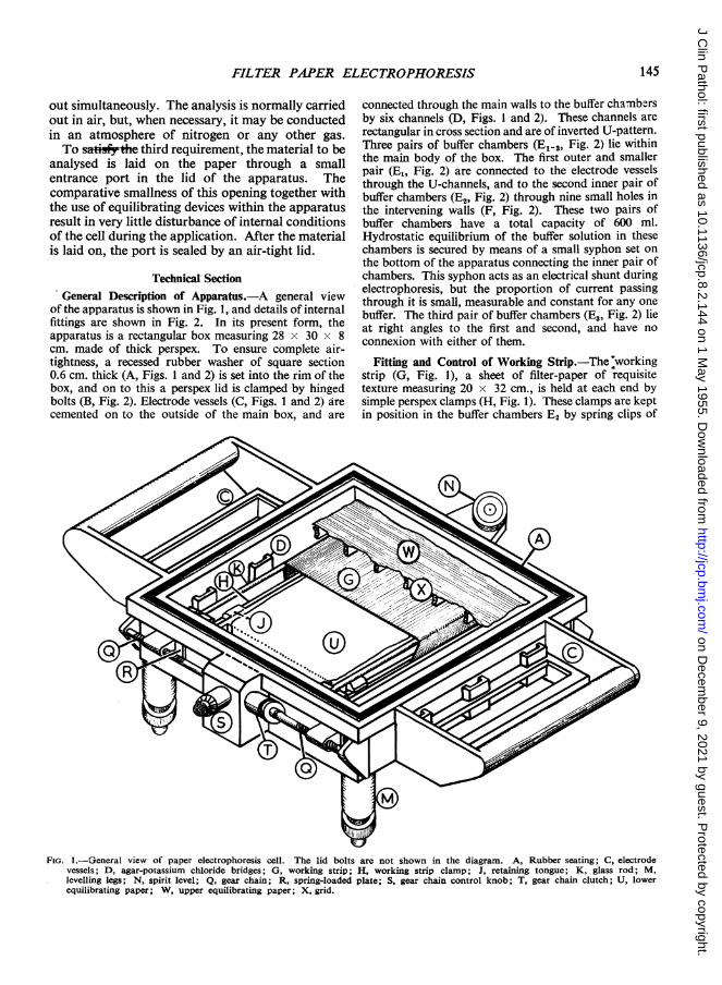
connected through the main walls to the buffer chambarsby six channels (D, Figs. 1 and 2). These channels arerectangular in cross section and are of inverted U-pattern.Three pairs of buffer chambers (El-,, Fig. 2) lie withinthe main body of the box. The first outer and smallerpair (E1, Fig. 2) are connected to the electrode vesselsthrough the U-channels, and to the second inner pair ofbuffer chambers (E2, Fig. 2) through nine small holes inthe intervening walls (F, Fig. 2). These two pairs ofbuffer chambers have a total capacity of 600 ml.Hydrostatic equilibrium of the buffer solution in thesechambers is secured by means of a small syphon set onthe bottom of the apparatus connecting the inner pair ofchambers. This syphon acts as an electrical shunt duringelectrophoresis, but the proportion of current passingthrough it is small, measurable and constant for any onebuffer. The third pair of buffer chambers (E., Fig. 2) lieat right angles to the first and second, and have noconnexion with either of them.
Fitting and Control of Working Strip.-The'workingstrip (G, Fig. 1), a sheet of filter-paper of requisitetexture measuring 20 x 32 cm., is held at each end bysimple perspex clamps (H, Fig. 1). These clamps are keptin position in the buffer chambers E2 by spring clips of
FIG. I.-General view of paper electrophoresis cell. The lid bolts are not shown in the diagram. A, Rubber seating; C, electrodevessels; D, agar-potassium chloride bridges; G, working strip; H, working strip clamp; J, retaining tongue; K, glass rod; M,levelling legs; N, spirit level; Q, gear chain; R, spring-loaded plate; S, gear chain control knob; T, gear chain clutch; U, lowerequilibrating paper; W, upper equilibrating paper; X, grid.
145
on Decem
ber 9, 2021 by guest. Protected by copyright.
http://jcp.bmj.com
/J C
lin Pathol: first published as 10.1136/jcp.8.2.144 on 1 M
ay 1955. Dow
nloaded from
G. T. FRANGLEN, N. H. MARTIN, and J. D. TREHERNE
FIG. 2.-Details of internal fittings of paper electrophoresis cell. A, Rubber seating; B, lid bolts; C, electrode vessels; D, agar-potassiumchloride bridges; Elt3, buffer chambers; F,S buffar chamber wall; J, retaining tongue; L, sliding block; 0, sliding block shelf; P,slot; Q, gear chain; V, central well.
perspex under small projecting tongues (J, Figs. 1 and 2).The paper thus fixed passes up to and is stretchedhorizontally across two glass rods (K, Fig. 1) whichrest in sloping slots cut in perspex blocks (L, Fig. 2).The whole apparatus is mounted on three levelling legs(M, Fig. 1), similar to those of an analytical balance, andis provided with a spirit level (N, Fig. 1) so that the levelof the paper stretched between these rods can be adjustedto be exactly horizontal. The blocks, which support therods, rest against the side of the apparatus on littleshelves (0, Fig. 2) above the buffer chambers, and areconnected through narrow slots (P, Fig. 2) to a gearchain (Q, Figs. I and 2) on the outside. The slots aremade air-tight by spring-loaded plates (R, Fig. 1).On rotation of a centrally placed control knob (S, Fig. 1),the gear chain produces outward parallel movement ofthe glass rods to take up slack in the working strip; incases where the sag is uneven, correction is made byaltering the set of the glass rods to each other by means ofa clutch (T, Fig. 1) on one side of the gear chain. Thecontrol knob is graduated in terms of distance betweenthe two glass rods; this enables reproducible tension to beapplied to the working strip, given the length and typeof filter paper used.
Maintenance of Internal Atmosphere.-Two sheets ofthick filter paper (" equilibrating papers ") dip into thethird pair of buffer chambers E3, and run across theapparatus 1 cm. above and below the working strip.
The lower paper (U, Fig. 1) is supported on a perspexplate covering the central well (V, Fig. 2); the upperpaper (W, Fig. 1) rests on a light perspex grid (X, Fig. I)over the working strip. Both sheets are thoroughly soakedin the buffer solution used on the working strip, andare kept wet by more buffer solution in the chambers E,.By this means, the atmosphere about the working stripis kept completely saturated with water vapour, and anyevaporation from the working strip is compensated byback-evaporation from the equilibrating papers. It mustbe noted that it is essential to use exactly the same buffersolution on the equilibrating papers and on the workingstrip; in practically all cases the use of water or othersalt solutions on the equilibrating strips results in anunstable internal atmosphere, and in marked distortionof the electrophoretogram. When using buffers at pHabove 9, no carbon dioxide should be present in theatmosphere if the buffer is to maintain its pH effectively.Using such buffers for electrophoresis, it has been foundan advantage to be able to conduct the separation in acarbon-dioxide-free atmosphere. Accordingly, specialinlets have been constructed in the lid to enable theapparatus to be flushed free of air, and filled with purenitrogen or with other gases before electrophoresis isstarted.
Application of Material.-A narrow rectangularentrance port is cut in the main lid. The material to beanalysed is applied through this port on to the wet
146
on Decem
ber 9, 2021 by guest. Protected by copyright.
http://jcp.bmj.com
/J C
lin Pathol: first published as 10.1136/jcp.8.2.144 on 1 M
ay 1955. Dow
nloaded from
FILTER PAPER ELECTROPHORESIS
working strip by an " Agla " micrometer syringe(Trevan, 1925) or by other suitable means. A small slit,cut in the upper equilibrating paper directly under theport, allows access to the working strip with the minimumdisturbance of the internal atmosphere of the apparatus.After the material has been applied, the port is sealed bya small rubber-seated lid clamped on by swing bolts.A number of lids with different entrance ports have beenconstructed to fit the main apparatus for use in varioustypes of analyses.
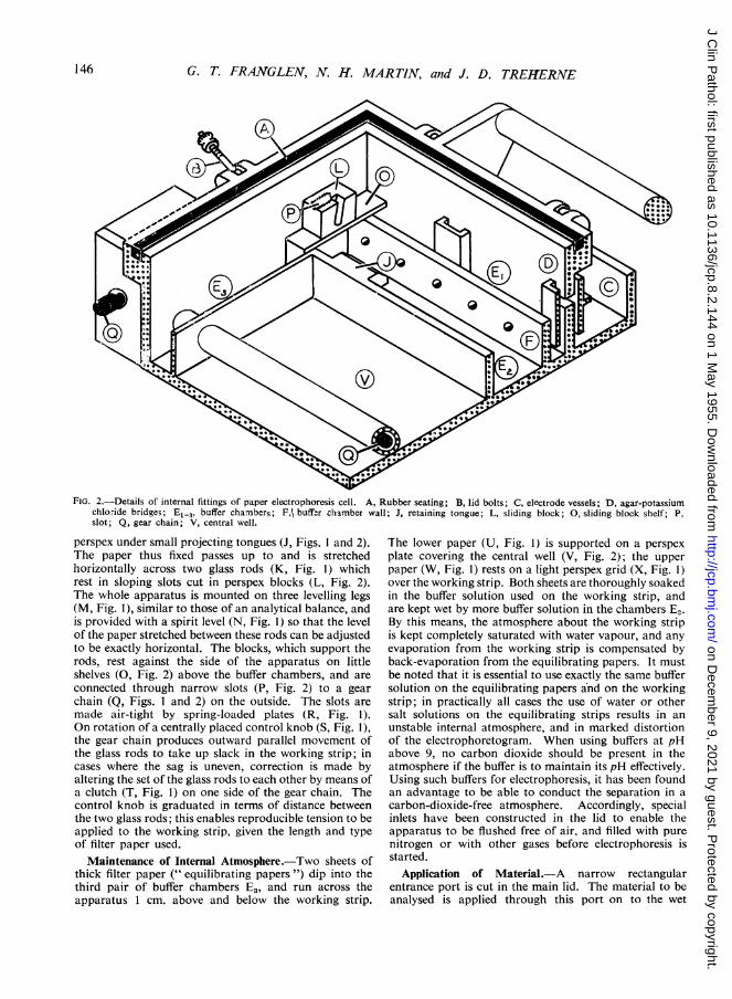
Electrode System.-Direct current from a suitablestabilizer is supplied to the apparatus through the fullyreversible sitver - silver chloride - potassium chlorideelectrodes which are connected to the buffer chambers E1by agar-potassium chloride bridges. The electrodes areenclosed in protective carriers (Fig. 3) which fit snuglyinto the electrode vessels. These carriers are five-sidedrectangular boxes of perspex, each holding a spirally
carrier.
grooved perspex rod of 1 cm. diameter. Fine silver wire,0.1 cm. in diameter, cleaned of all traces of grease, iswound on to the groove by rotating the rod in the carrier,and is attached to the terminal on the upper side of thecarrier. About 210 cm. of wire is used in each electrodegiving an electrode area of over 60 cm.2 After beingwound on to the rod, the wire is cleaned still further bybeing soaked for one minute in nitric acid (reagent grade)diluted to one third with distilled water, and followed bybeing rinsed thoroughly in distilled water. The electrodeis stood in a plating bath of N/10 hydrochloric acid(reagent grade) so that the silver wire on the rod iscompletely immersed; the terminal head should not bebelow the surface of the liquid. The positive pole of a
D.C. supply is connected to the electrode, while thenegative pole is connected to a platinum electrodestanding in the plating bath. A potential difference of2 to 4 V. is maintained across the electrodes in the bathfor not less than four hours, and preferably overnight.As plating proceeds, the current falls to a small value, anda dark pink deposit of silver chloride is formed on the
wire. After plating the electrodes are rinsed free ofhydrochloric acid with distilled water.
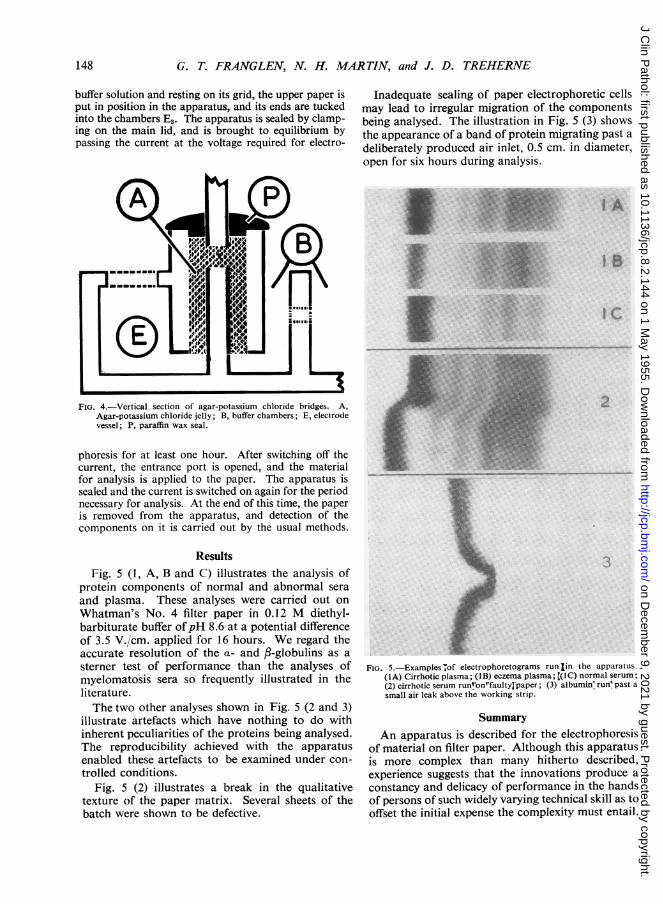
Agar-potassium chloride bridges are formed betweenthe electrode vessels and the buffer chambers El byfilling the U-channels described above with a hot solutionof 1% (w/v) pure agar in 3.5 M aqueous potassiumchloride (reagent grade). When this has set, the opentops of these channels are sealed with a layer of hardparaffin wax (Fig. 4). Provided they are prevented fromdrying out, these bridges can be used for months at atime without interference. When changing them, theparaffin seal is broken off, and the bridge channels arecleaned of agar with a fine test-tube brush. The electrodevessels are filled with 150 ml. of 3.5 M aqueous potassiumchloride solution; the electrodes in their carriers areinserted into them and attached to a suitable D.C.
supply. After each run, the pola-rity of the electrodes must bereversed to prevent deplating thenegative side. They require no
-K~x<7 further attention other than anoccasional replating in N/10
--^~,' hydrochloric acid. When not inuse, they must always be kept indistilled water or in 3.5 M aque-ous potassium chloride solution,as they are ruined if allowed todry out.
Method of Operation.-Theapparatus is placed on the labora-tory bench out of draughts, andtrued by means of the attachedspirit level. Alternatively it canbe placed in a thermostaticallycontrolled cabinet, if analysis attemperatures other than normalroom temperatures is contem-plated. The electrodes are setup as described above, and areconnected to a stabilized D.C.
supply. On the sheet of perspex, which covers the centralwell (V, Fig. 2), a thick sheet of filter paper (Whatman'sNo. 3MM) is laid and soaked with the buffer solution tobe used in the analysis; this forms the lower equilibratingpaper. More buffer solution, about 10 ml., is added toeach of the chambers E3. The dry working strip ismounted in the clamps, and is put in position in theapparatus; the clamps are fixed securely in the chambersE2 by the perspex clips. The position of the rods isadjusted by the control knob until the paper is stretchedtaut. Buffer solution, 300 ml., is added to the chambersE1 and E2 on each side of the apparatus. The workingstrip is allowed to take up the buffer naturally; it shouldnot be sprayed with buffer solution in an effort to hastenthe uptake, as this often results in an uneven surface.When the working strip is completely wet the positionof the rods is adjusted again to take up any sag and togive the required tension on the paper. The upper
equilibrating paper, cut from a sheet of thick filter paper,is fitted on to the perspex grid; a narrow slot is cut in thispaper under the entrance port in the main lid. Soaked in
FIG. 3.-Electrode for paper electro-phoresis cell. Part of the carrier hasbeen cut away to show the silverwire wound on to the rod inside.This wire is attached to the terminalscrew on the top of the electrode
147
on Decem
ber 9, 2021 by guest. Protected by copyright.
http://jcp.bmj.com
/J C
lin Pathol: first published as 10.1136/jcp.8.2.144 on 1 M
ay 1955. Dow
nloaded from
G. T. FRANGLEN, N. H. MAR TIN, and J. D. TREHERNE
buffer solution and resting on its grid, the upper paper isput in position in the apparatus, and its ends are tuckedinto the chambers E3. The apparatus is sealed by clamp-ing on the main lid, and is brought to equilibrium bypassing the current at the voltage required for electro-
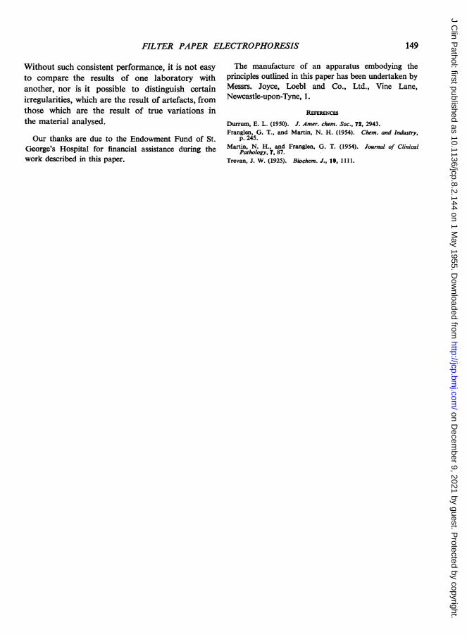
Inadequate sealing of paper electrophoretic cellsmay lead to irregular migration of the componentsbeing analysed. The illustration in Fig. 5 (3) showsthe appearance of a band of protein migrating past adeliberately produced air inlet, 0.5 cm. in diameter,open for six hours during analysis.
I A
I B
iC
FIG. 4.-Vertical section of agar-potassium chloride bridges. A,Agar-potassium chloride jelly; B, buffer chambers; E, electrodevessel; P, paraffin wax seal.
phoresis for at least one hour. After switching off thecurrent, the entrance port is opened, and the materialfor analysis is applied to the paper. The apparatus issealed and the current is switched on again for the periodnecessary for analysis. At the end of this time, the paperis removed from the apparatus, and detection of thecomponents on it is carried out by the usual methods.
ResultsFig. 5 (1, A, B and C) illustrates the analysis of
protein components of normal and abnormal seraand plasma. These analyses were carried out onWhatman's No. 4 filter paper in 0.12 M diethyl-barbiturate buffer ofpH 8.6 at a potential differenceof 3.5 V./cm. applied for 16 hours. We regard theaccurate resolution of the a- and fl-globulins as asterner test of performance than the analyses ofmyelomatosis sera so frequently illustrated in theliterature.The two other analyses shown in Fig. 5 (2 and 3)
illustrate artefacts which have nothing to do withinherent peculiarities of the proteins being analysed.The reproducibility achieved with the apparatusenabled these artefacts to be examined under con-trolled conditions.
Fig. 5 (2) illustrates a break in the qualitativetexture of the paper matrix. Several sheets of thebatch were shown to be defective.
2.,
FIG. 5.-Examples ,of electrophoretograms runlin the apparatus.(IA) Cirrhotic plasma; (1B) eczema plasma; [(lc) normal serum;(2) cirrhotic serum runVon"faultyl paper; (3) albumin' run' past a
small air leak above the working strip.
SummaryAn apparatus is described for the electrophoresis
of material on filter paper. Although this apparatusis more complex than many hitherto described,experience suggests that the innovations produce aconstancy and delicacy of performance in the handsof persons of such widely varying technical skill as tooffset the initial expense the complexity must entail.
148
on Decem
ber 9, 2021 by guest. Protected by copyright.
http://jcp.bmj.com
/J C
lin Pathol: first published as 10.1136/jcp.8.2.144 on 1 M
ay 1955. Dow
nloaded from
FILTER PAPER ELECTROPHORESIS
Without such consistent performance, it is not easy
to compare the results of one laboratory withanother, nor is it possible to distinguish certainirregularities, which are the result of artefacts, fromthose which are the result of true variations inthe material analysed.
Our thanks are due to the Endowment Fund of St.George's Hospital for financial assistance during thework described in this paper.
The manufacture of an apparatus embodying theprinciples outlined in this paper has been undertaken byMessrs. Joyce, Loebl and Co., Ltd., Vine Lane,Newcastle-upon-Tyne, 1.
REFERENCES
Durrum, E. L. (1950). J. Amer. chem. Soc., 72, 2943.Franglen, G. T., and Martin, N. H. (1954). Chem. and Industry,
p. 245.Martin, N. H., and Franglen, G. T. (1954). Journal of Clinical
Pathology, 7, 87.Trevan, J. W. (1925). Biochem. J., 19, 1111.
149
on Decem
ber 9, 2021 by guest. Protected by copyright.
http://jcp.bmj.com
/J C
lin Pathol: first published as 10.1136/jcp.8.2.144 on 1 M
ay 1955. Dow
nloaded from