Embed Size (px)
Citation preview

Minutes of EFC WP15 Corrosion in the Refinery Industry 30 September 2003
Appendix 1
List of participants and excused persons
Minutes of EFC WP15 Corrosion in the Refinery Industry 30 September 2003
NAME COMPANY ADDRESS 2 ADDRESS 3 ADDRESS 4 ADDRESS 5Chris Fowler Bodycote Materials Testing 182 Halesowen Road,Netherton Dudley, W.Midlands DY2 9PL UK
Gerit Siegmund ExxonMobil Germany GfKorr Riethorst 12 30659 Hannover GERMANY
Istvan Lukovits Chemical Research Center Hungarian Academy of Sciences P.O.B. 17 1525 Budapest HUNGARY
Alec Groysman Oil Refineries Ltd PO Box 4 Haifa 31000 ISRAEL
Keith Lewis Shell Global Solutions International B.V. PO Box 38 000, 1030BN Amsterdam NETHERLANDS
François Ropital Institut Français du Pétrole 1-4 Avenue Bois Préau 92852 Rueil-Malmaison Cedex FRANCE
Maarten Lorenz Shell Global Solutions InetrnationalB.V.
Badhuiweg 3 PO Box 38000 1030 BN Amsterdam NETHERLANDS
Anni Visgaard Nielsen Statoil Refinery, Kalundborg, Melbyvej 17 4400 Kalundborg DENMARK
Arto Kiiski FORTUM OIL & GAS NESTE Engineering P.O. Box 310 Porvoo FIN-06101 FINLAND
Alan Turnbull National Physical Laboratory Teddington, Middlesex TW11 OLW UK
David Owen GE Betz Foundry Lane Widnes Cheshire WA8 8UD UK
Stefan Winnik Exxon Mobil Chemical Fawley Refinery Southampton SO45 1TX UK
Dr Laszlo Simor Danube Refinery MOL Hungarian Oil & Gas Co H-2443, POB1 Szazhalombatta H-2443 HUNGARY
Danilo Baldassarre Total Technical Assistance Division BP19 76700 Harfleur FRANCE
Joanna Hucinska Gdansk Technical University G Narutowicza St No 11 80-952 Gdansk POLAND
Giovanna Gabetta ENTRICERCHE - INGE Via F Maritano 26 20097 San Donato Milanese (MI) ITALY
Gorton Jonathan Bechtel Ltd 245 Hammersmith Road PO Box 739 London W6 8DP UK
Hennie de Bruyn Statoil ASA Arkitekt Ebbellsvei 10, Rotvoll Postuttak N-7005 Trondheim NORWAY
Liane Smith Intetech Ltd 37, Mount Way Waverton Chester CH3 7QF UK
Gérard Broye Technip France La Défense 12 92973 Paris La Défense Cedex FRANCE
Andrew M Pritchard Corrosion & Fouling Consultancy 33 Laburnum Road Oxford OX2 9EL UK
Russell Kane Intercorr Suite 300 14503 bammel northhouston
Houston TX 77017 USA
Participants EFC WP15 meeting 30th September 2003 Budapest
Minutes of EFC WP15 Corrosion in the Refinery Industry 30 September 2003
NAME COMPANY ADDRESS 2ADDRESS 3
ADDRESS 4 ADDRESS5
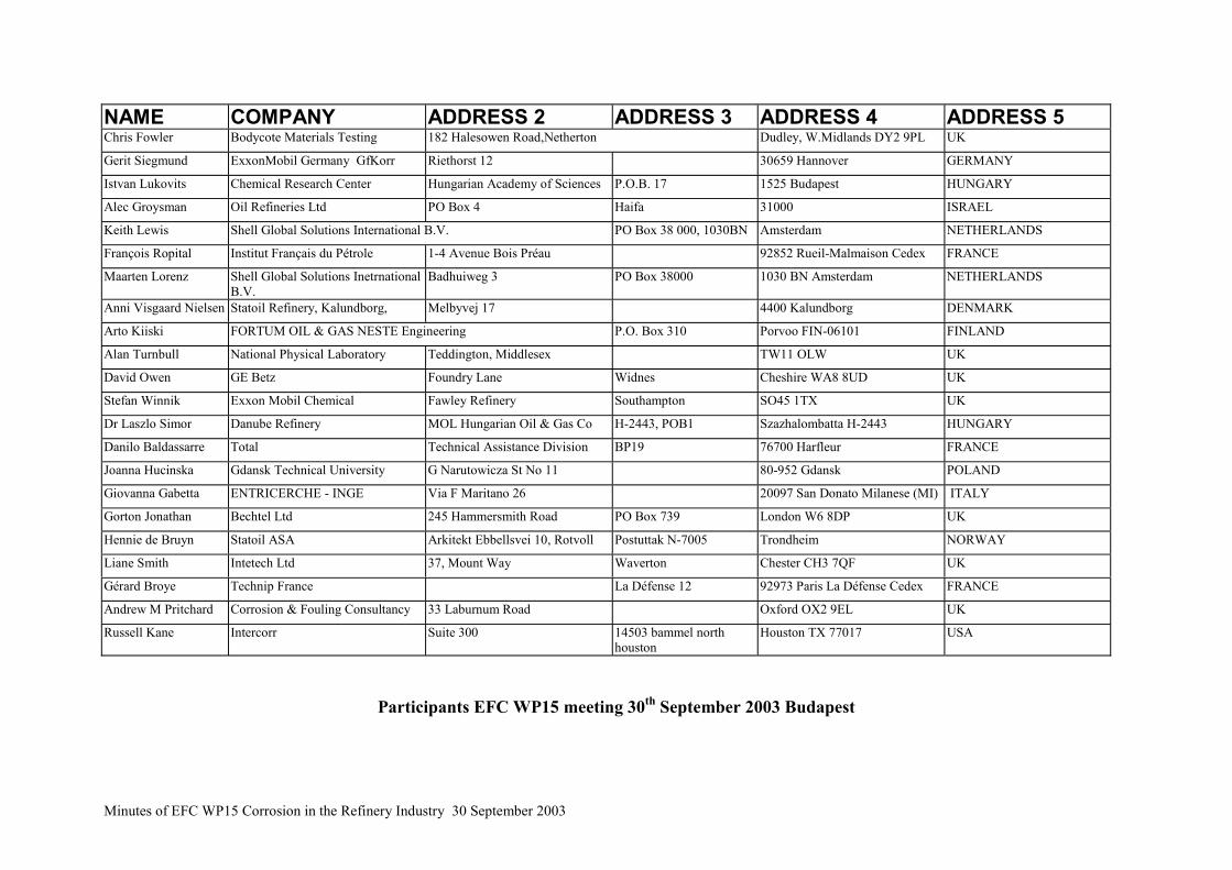
Andrew Kettle Chevron Texaco Ltd Pembroke Plant Pembs Wales SA71 5SJ UK
Leslie Antalffy Fluor Daniel One Fluor Daniel Drive Sugar Land Texas, 77478 USA
Mr Terry Hallett Shell UK ltd Stanlow Manufacturing Complex PO Box 3, OilSites Road
Ellesmere Port UK
Martin Hofmeister Bayernoil Raffineriegesellschaft mbH Postfach 100858 85008 Ingolstadt GERMANY
Guenter Luxenburger Dillinger Huttenwerke PO Box 1580 D-66748 Dillingen GERMANY
Hervé Marchebois IPEDEX SAS 366, Avenue Napoléon Bonaparte BP 205 92500 Rueil Malmaison FRANCE
Kirsi Rintamaki FORTUM OIL & GAS NESTE Engineering P.O. Box 310 Porvoo FIN-06101 FINLAND
Tiina Hakonen FORTUM Oil & Gas Oy PO Box 310 FIN-06101 Porvoo FINLAND
Chris M Chis Bechtel Ltd 245 Hammersmith Road PO Box 739 London W6 8DP UK
Martin Richez Total Technical Assisiatnce Division BP19 76700 Harfleur FRANCE
Charles Droz Exxon Mobil BP No 1 76330 N.D.Gravenchon FRANCE
Philippe Fevrier Shell Pétrochimie Méditerranée Département Engineering - Matériel - EEXP BP No 14 13131 Berre l'Etang Cedex FRANCE
Richard Carroll Foster Wheeler Energy Shinfield Park Reading Berkshire, RG2 9FW UK
José Maria Barragan CEPSA Refinería La Rábida 21080 HUELVA SPAIN
Dr Michael Davies CARIAD Consultants Kato Asites Heraklion Crete 70013 GREECE
Steve McCoy Special Metals Wiggin Ltd Holmer Road Hereford HR49SL UK
Jean Luc Themiot BP Raffinerie BP BP 15 13117 LAVERA FRANCE
Lionel Coudreuse Industeel 56 Rue Clemenceau BP 56 71202 Le Creusot Cedex FRANCE
Chris M Chis Bechtel Ltd 245 Hammersmith Road PO Box 739 London W6 8DP UK
Frank Dean Ion Science Ltd The Way, Fowlmere Cambridge SG8 7UJ UK
Wim Verstijnen Shell Nederland Raffinaderij B.V. Vondelingenweg 601 Postbus 3000 3190 GA Hoogvliet NETHERLANDS
Nicholas Dowling Shell Global Solutions International B.V. PO Box 38 000 1030BN Amsterdam NETHERLANDS
Excuses received for the EFC WP15 meeting 30th October 2003 Budapest
Minutes of EFC WP15 Corrosion in the Refinery Industry 30 September 2003
Appendix 2
Study of Corrosiveness of acidic crude oil and
its fractions
Dr Alec Groysman Oil Refineries Ltd.
1
Study of Corrosiveness of Acidic Study of Corrosiveness of Acidic Crude Oil and its Fractions Crude Oil and its Fractions
Dr. Alec GroysmanDr. Alec Groysman
Oil Refineries Ltd., Oil Refineries Ltd., Haifa, Israel Haifa, Israel
The goalsThe goals::•• Determination of corrosiveness Determination of corrosiveness of acidic crude oil of acidic crude oil ““AA”” and its and its fractions. fractions.2. The choice of mitigation 2. The choice of mitigation measures. measures.3. Examination of corrosion3. Examination of corrosion inhibitor for acidic kerosene inhibitor for acidic kerosene fraction in the distillation unit. fraction in the distillation unit.
2
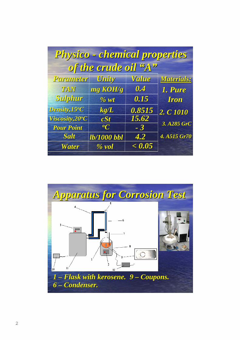
PhysicoPhysico - chemical properties - chemical properties of the crude oil of the crude oil ““AA””ParameterParameter UnityUnity ValueValue
TANTANSulphurSulphur
mg KOH/gmg KOH/g
% wt% wtDensity,15Density,15ooCC kg/Lkg/L
cStcStooCC - 3- 3
Viscosity,20Viscosity,20ooCC
Pour PointPour PointSaltSalt
WaterWaterlb/1000 bbllb/1000 bbl
% % volvol
0.40.40.150.15
0.85150.851515.6215.62
4.24.2< 0.05< 0.05
1. Pure1. Pure Iron Iron
Materials:Materials:
2. C 10102. C 1010
3. A285 3. A285 GrCGrC
4. A515 Gr704. A515 Gr70
Apparatus for Corrosion TestApparatus for Corrosion Test
1 1 –– Flask with kerosene. Flask with kerosene.6 6 –– Condenser. Condenser.
9 9 –– Coupons. Coupons.
3
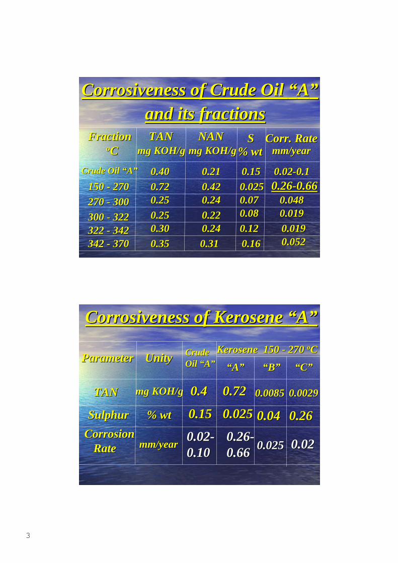
Corrosiveness of Crude Oil Corrosiveness of Crude Oil ““AA””and its fractionsand its fractions
FractionFraction ooCC
TANTANmg KOH/gmg KOH/g
SSNANNANmg KOH/gmg KOH/g
CorrCorr. Rate. Ratemm/yearmm/year% wt% wt
Crude Oil Crude Oil ““AA””
150 - 270150 - 270
270 - 300270 - 300
300 - 322300 - 322322 - 342322 - 342342 - 370342 - 370
0.400.40 0.210.21
0.720.72 0.420.420.250.25 0.240.24
0.250.25 0.220.220.300.30 0.240.24
0.310.310.350.35
0.150.15
0.0250.0250.070.070.080.08
0.120.12
0.160.16
0.02-0.10.02-0.10.26-0.660.26-0.66
0.0480.0480.0190.019
0.0190.0190.0520.052
Corrosiveness of Kerosene Corrosiveness of Kerosene ““AA””
ParameterParameter UnityUnity
TANTAN mg KOH/gmg KOH/g
SulphurSulphur
Corrosion Corrosion Rate Rate
% wt% wt
Kerosene 150 - 270 Kerosene 150 - 270 ooCC Crude Crude Oil Oil ““AA””
mm/yearmm/year
““AA”” ““BB””
0.40.4
0.150.15
0.02-0.02-0.100.10
0.720.72
0.0250.025
0.26-0.26-0.660.66
0.00850.0085 0.0029 0.0029
0.040.04 0.260.26
0.0250.025 0.020.02
““CC””
4
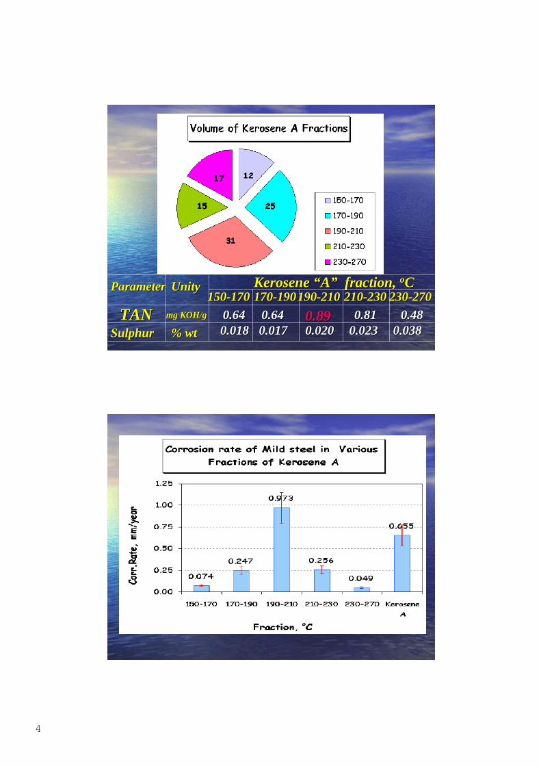
ParameterParameter UnityUnity Kerosene Kerosene ““AA”” fraction, fraction, ooCC
TANTANSulphurSulphur
mg KOH/gmg KOH/g
% wt% wt
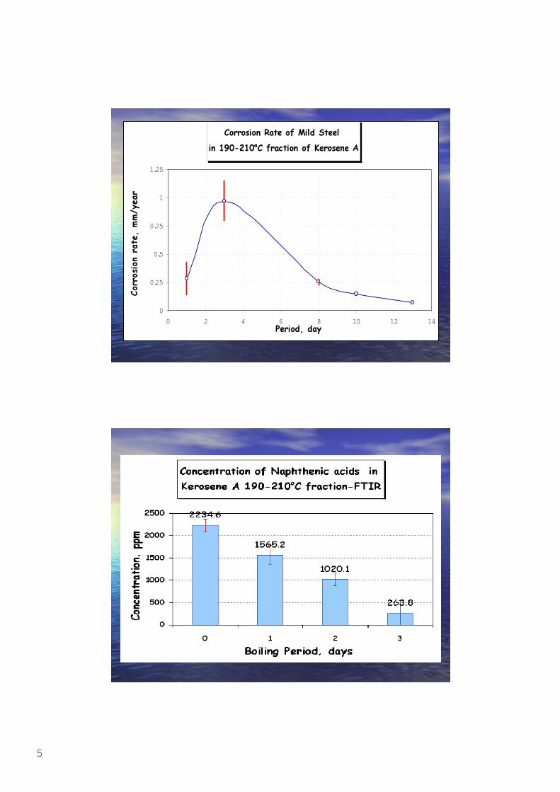
150-170150-170 170-190170-190 190-210190-210 210-230210-230
0.640.64 0.640.64 0.890.89 0.810.81230-270230-270
0.480.480.0180.018 0.0170.017 0.0200.020 0.0230.023 0.0380.038
5
���������������� ���������
���������������������������������
0
0.25
0.5
0.75
1
1.25
0 2 4 6 8 10 12 14����������
������
����
��
������
��
6
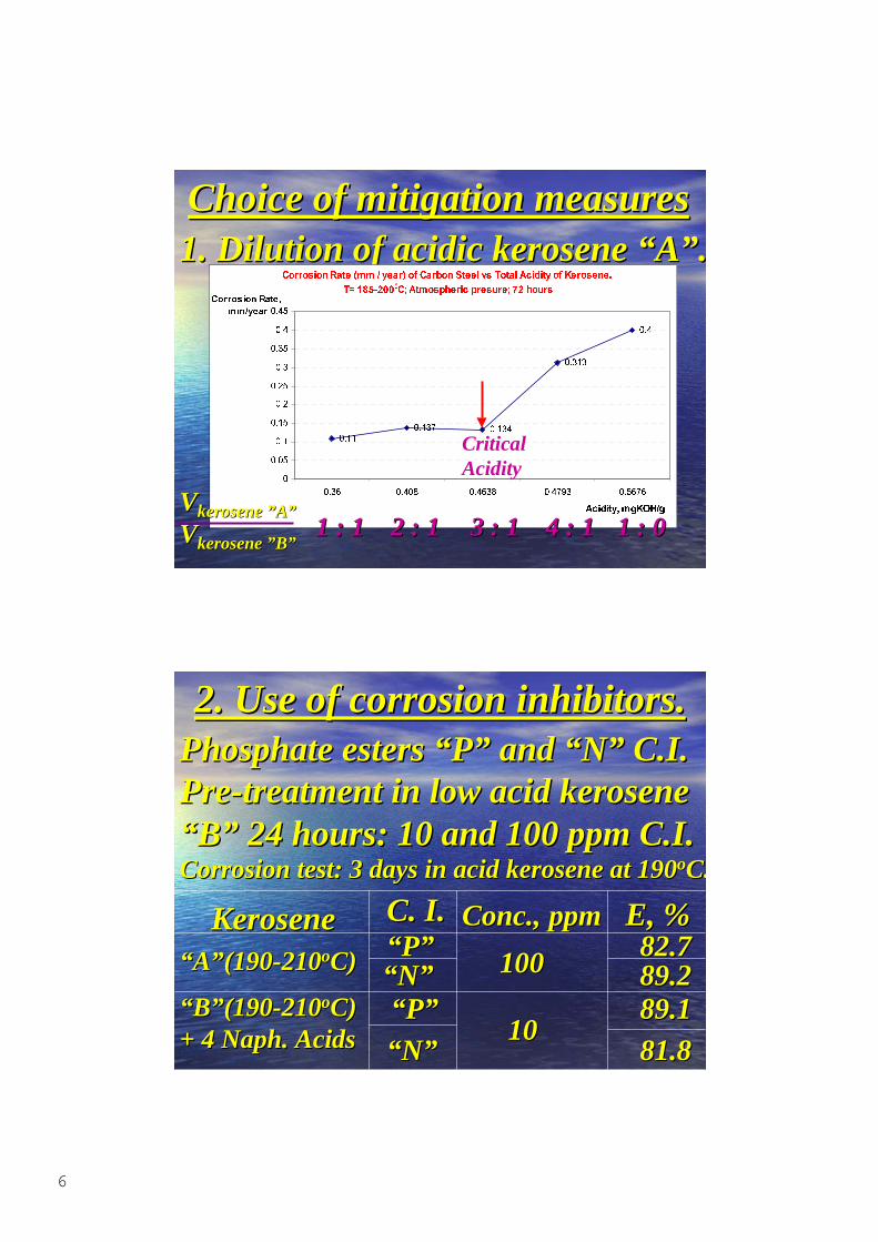
Choice of mitigation measuresChoice of mitigation measures1. Dilution of acidic kerosene 1. Dilution of acidic kerosene ““AA””..
�������������� �������������������������������������������������
������ !""����������� �����������������
����
����� �����
�����
���
�
����
���
����
���
����
���
����
���
����
��� ���� ���� ������ ����
�� � �����������
��������������
����
CriticalAcidity
VVkerosenekerosene ””AA””
VVkerosenekerosene ””BB””1 : 11 : 1 2 : 12 : 1 3 : 13 : 1 4 : 14 : 1 1 : 01 : 0
2. Use of corrosion inhibitors.2. Use of corrosion inhibitors.Phosphate esters Phosphate esters ““PP”” and and ““NN”” C.I. C.I.Pre-treatment in low acid kerosenePre-treatment in low acid kerosene““BB”” 24 hours: 10 and 100 ppm C.I. 24 hours: 10 and 100 ppm C.I.Corrosion test: 3 days in acid kerosene at 190Corrosion test: 3 days in acid kerosene at 190ooC.C.
KeroseneKerosene C. I.C. I. Conc.,Conc., ppmppm E, %E, %““AA””(190-210(190-210ooC)C)
““BB””(190-210(190-210ooC)C)+ 4 + 4 NaphNaph. Acids. Acids
““PP””““NN””
““NN””““PP””
100100
1010
82.782.789.289.289.189.1
81.881.8
7
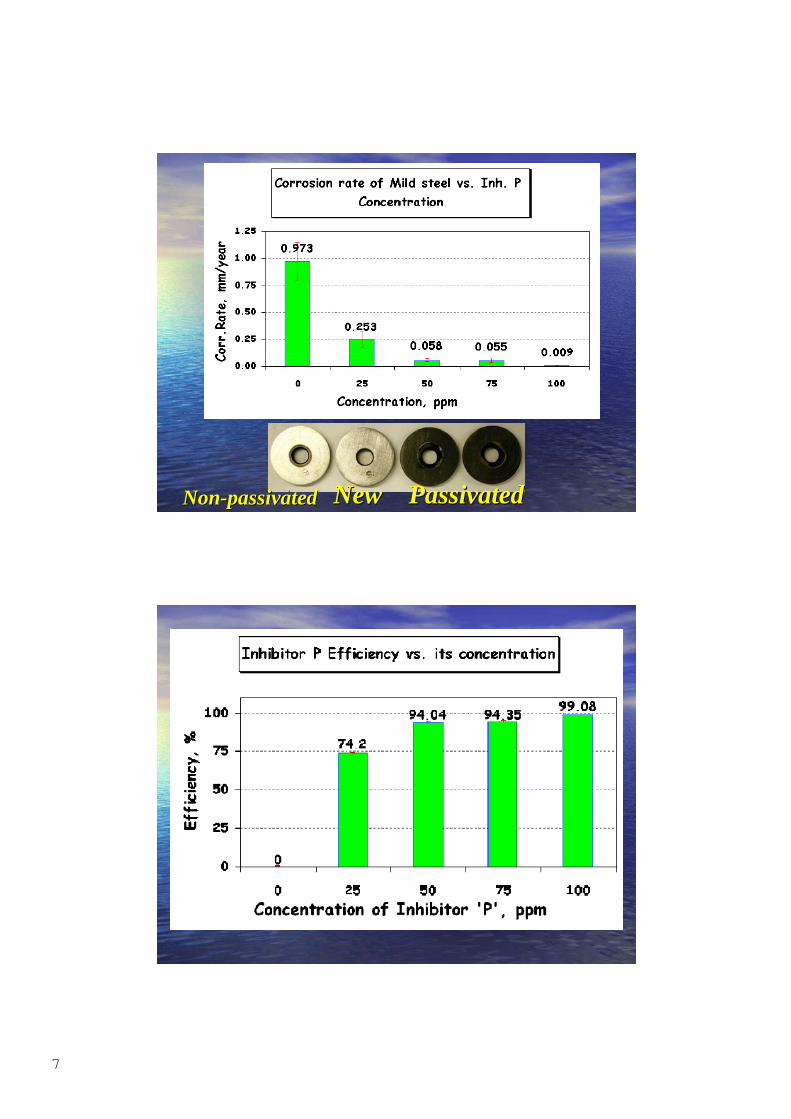
NewNew PassivatedPassivatedNon-Non-passivatedpassivated
8
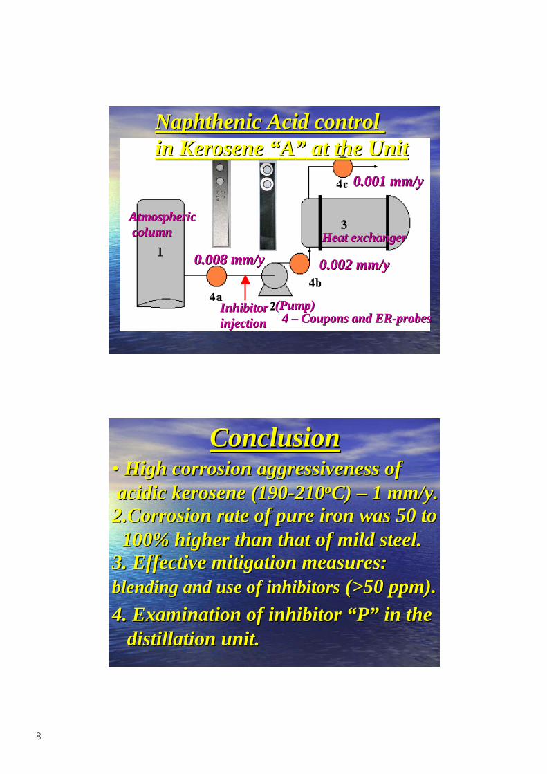
Naphthenic Acid control Naphthenic Acid control in Kerosene in Kerosene ““AA”” at the Unit at the Unit
AtmosphericAtmospheric column column
(Pump)(Pump)
Heat exchangerHeat exchanger
4 4 –– Coupons and ER-probes Coupons and ER-probes
0.008 mm/y0.008 mm/y 0.002 mm/y0.002 mm/y
0.001 mm/y0.001 mm/y
InhibitorInhibitorinjectioninjection
ConclusionConclusion•• High corrosion aggressiveness ofHigh corrosion aggressiveness of acidic kerosene (190-210 acidic kerosene (190-210ooC) C) –– 1 mm/y. 1 mm/y. 2.Corrosion rate of pure iron was 50 to2.Corrosion rate of pure iron was 50 to 100% higher than that of mild steel. 100% higher than that of mild steel. 3. Effective mitigation measures:3. Effective mitigation measures:blending and use of inhibitorsblending and use of inhibitors (>50 ppm). (>50 ppm). 4. Examination of inhibitor 4. Examination of inhibitor ““PP”” in the in the distillation unit. distillation unit.
Minutes of EFC WP15 Corrosion in the Refinery Industry 30 September 2003
Appendix 3
Shell Non Intrusive Inspection
Optimised Inspection Planning based on S-RBI
Maarten Lorenz Shell Global Solutions
Shell Global Solutions
Shell Non-Intrusive InspectionOptimised Inspection Planning based on S-RBI
Presented by:Maarten Lorenz
Material & Inspection TechnologyShell Research & Technology Centre
Amsterdam, The [email protected]
EFC WP15 September 2003© 2003 Shell Global Solutions International B.V.
Shell Global Solutions 2
EFC WP15 September 2003© 2003 Shell Global Solutions International B.V.
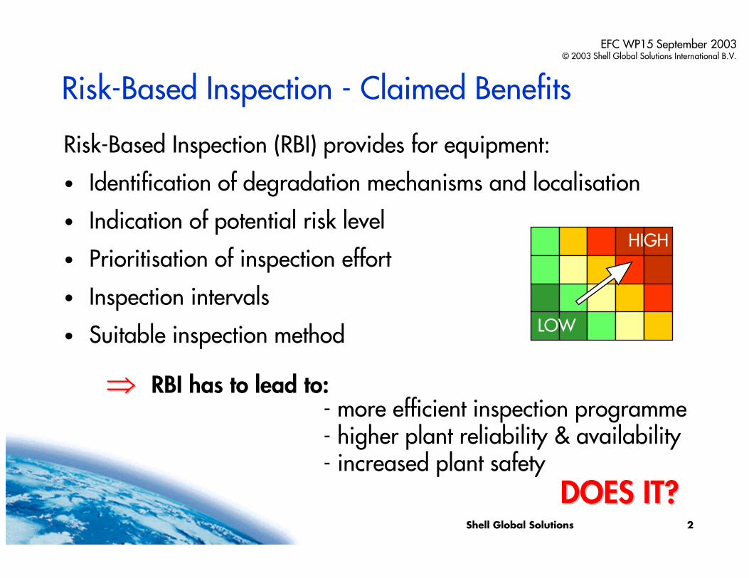
Risk-Based Inspection - Claimed Benefits
Risk-Based Inspection (RBI) provides for equipment:
• Identification of degradation mechanisms and localisation
• Indication of potential risk level
• Prioritisation of inspection effort
• Inspection intervals
• Suitable inspection method
⇒ ⇒ RBI has to lead to:
HIGH
LOW
- more efficient inspection programme- higher plant reliability & availability- increased plant safety
DOES IT?DOES IT?
Shell Global Solutions 3
EFC WP15 September 2003© 2003 Shell Global Solutions International B.V.
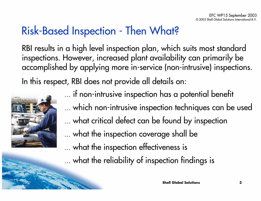
Risk-Based Inspection - Then What?
… if non-intrusive inspection has a potential benefit
… which non-intrusive inspection techniques can be used
… what critical defect can be found by inspection
… what the inspection coverage shall be
… what the inspection effectiveness is
… what the reliability of inspection findings is
RBI results in a high level inspection plan, which suits most standard inspections. However, increased plant availability can primarily be accomplished by applying more in-service (non-intrusive) inspections.
In this respect, RBI does not provide all details on:
Shell Global Solutions 4
EFC WP15 September 2003© 2003 Shell Global Solutions International B.V.
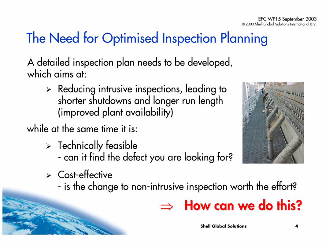
The Need for Optimised Inspection Planning
A detailed inspection plan needs to be developed,which aims at:
Reducing intrusive inspections, leading toshorter shutdowns and longer run length(improved plant availability)
while at the same time it is:
Technically feasible- can it find the defect you are looking for?
Cost-effective- is the change to non-intrusive inspection worth the effort?
⇒⇒ How can we do this?How can we do this?
Shell Global Solutions 5
EFC WP15 September 2003© 2003 Shell Global Solutions International B.V.
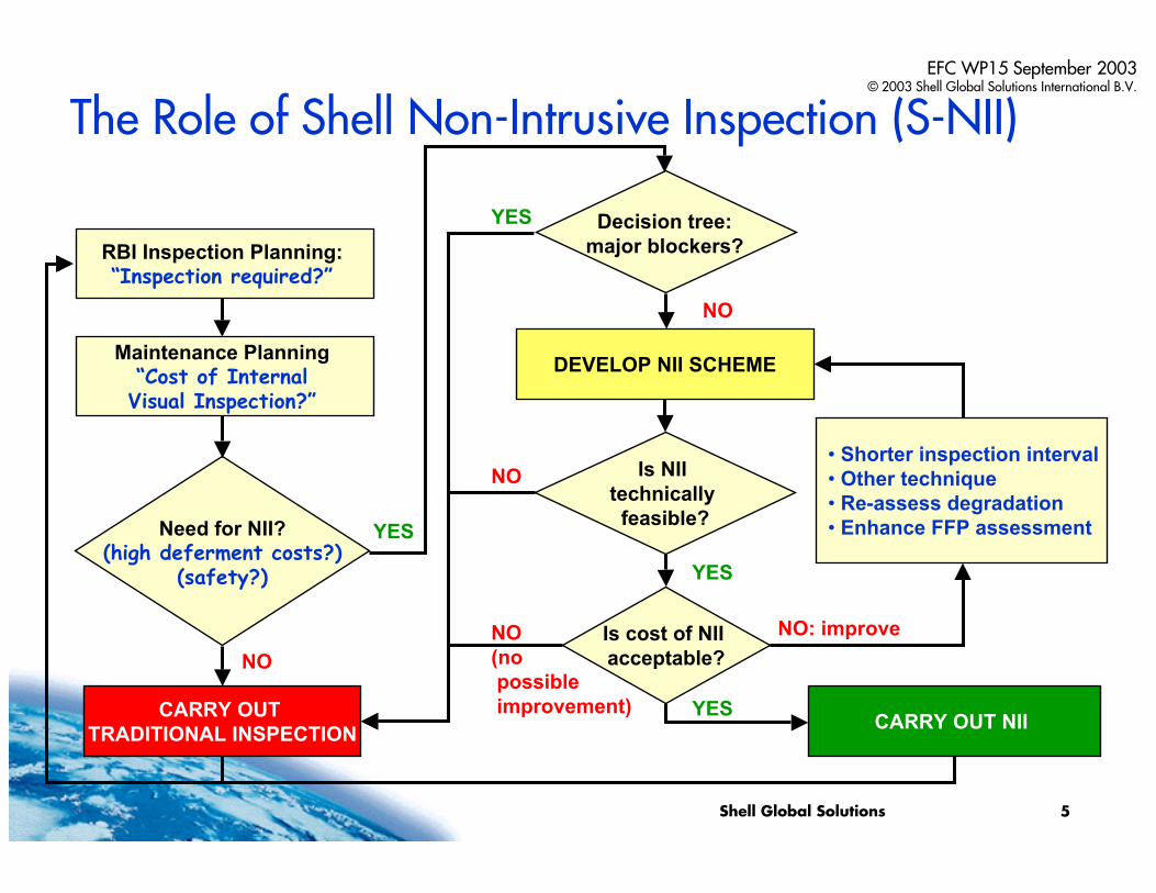
RBI Inspection Planning:“Inspection required?”
Maintenance Planning“Cost of InternalVisual Inspection?”
DEVELOP NII SCHEME
CARRY OUT NII CARRY OUT TRADITIONAL INSPECTION
Need for NII?(high deferment costs?)
(safety?)
YES
NO
Is NII technically
feasible?
NO
Is cost of NII acceptable?
YES
• Shorter inspection interval • Other technique• Re-assess degradation• Enhance FFP assessment
YES
NO: improve
Decision tree:major blockers?
YES
NO
The Role of Shell Non-Intrusive Inspection (S-NII)
NO(nopossibleimprovement)
Shell Global Solutions 6
EFC WP15 September 2003© 2003 Shell Global Solutions International B.V.
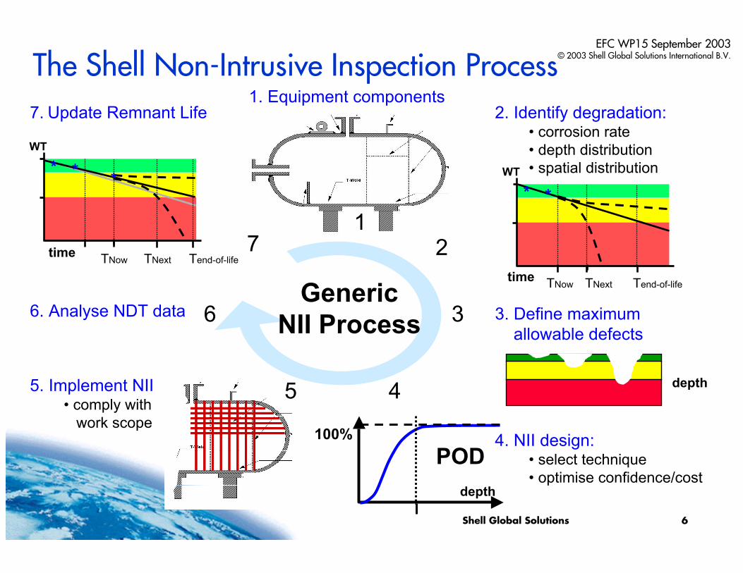
2. Identify degradation:• corrosion rate• depth distribution • spatial distribution
4. NII design:• select technique• optimise confidence/cost
1. Equipment components
6. Analyse NDT data
POD100%
depth
12
3
45
7
Generic NII Process 3. Define maximum
allowable defects
5. Implement NII• comply with
work scope
6
7. Update Remnant Life
The Shell Non-Intrusive Inspection Process
depth
WT
TNextTNowtime
* * *
Tend-of-life
WT
TNextTNowtime
* *
Tend-of-life
Shell Global Solutions 7
EFC WP15 September 2003© 2003 Shell Global Solutions International B.V.
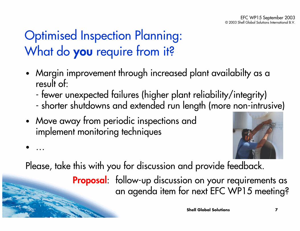
Optimised Inspection Planning: What do you require from it?
• Margin improvement through increased plant availabilty as a result of:- fewer unexpected failures (higher plant reliability/integrity)- shorter shutdowns and extended run length (more non-intrusive)
• Move away from periodic inspections andimplement monitoring techniques
• …
Please, take this with you for discussion and provide feedback.Proposal: follow-up discussion on your requirements as
an agenda item for next EFC WP15 meeting?
Shell Global Solutions
Shell Non-Intrusive InspectionEffective Inspection Planning based on S-RBI
- thank you for your attention -ANY QUESTIONS OR REMARKS?
Presented by:Maarten Lorenz
Material & Inspection TechnologyShell Research & Technology Centre
Amsterdam, The [email protected]
EFC WP15 September 2003© 2003 Shell Global Solutions International B.V.
Minutes of EFC WP15 Corrosion in the Refinery Industry 30 September 2003
Appendix 4
Piping System CUI
Old problem; Different Approaches
Stefan Winnik Exxon Mobil
Piping System CUI:Old Problem; Different ApproachesPiping System CUI:Piping System CUI:Old Problem; Different ApproachesOld Problem; Different Approaches
Brian J. FitzgeraldCharles DrozStefan Winnik
Exxon Mobil Chemical Company
Brian J. FitzgeraldBrian J. FitzgeraldCharles DrozCharles DrozStefan WinnikStefan Winnik
Exxon Mobil Chemical CompanyExxon Mobil Chemical Company
European Federation of CorrosionSeptember 2003
Discussion OutlineDiscussion OutlineDiscussion Outline
• CUI Background and Examples• CUI Leak Data & Maintenance Costs• CUI Prevention Measures• CUI Prevention Costs• CUI Prevention Strategy
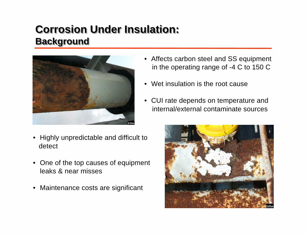
Corrosion Under Insulation:BackgroundCorrosion Under Insulation:Corrosion Under Insulation:BackgroundBackground
• Highly unpredictable and difficult to detect
• One of the top causes of equipmentleaks & near misses
• Maintenance costs are significant
• Affects carbon steel and SS equipment in the operating range of -4 C to 150 C
• Wet insulation is the root cause
• CUI rate depends on temperature and internal/external contaminate sources
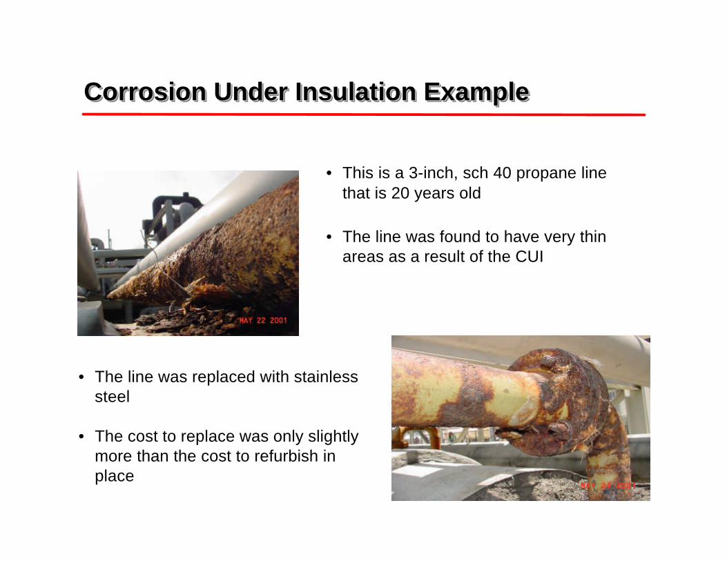
• This is a 3-inch, sch 40 propane linethat is 20 years old
• The line was found to have very thinareas as a result of the CUI
Corrosion Under Insulation ExampleCorrosion Under Insulation ExampleCorrosion Under Insulation Example
• The line was replaced with stainlesssteel
• The cost to replace was only slightlymore than the cost to refurbish inplace
Corrosion Under Insulation ExampleCorrosion Under Insulation ExampleCorrosion Under Insulation Example
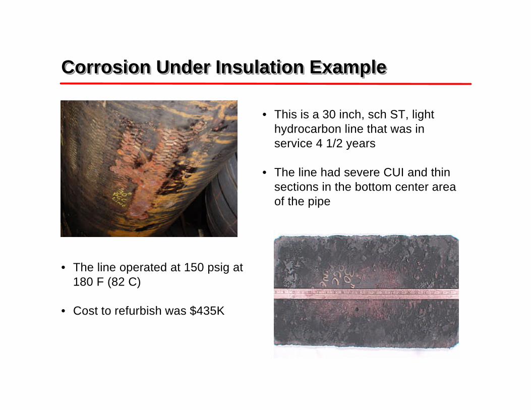
• This is a 30 inch, sch ST, lighthydrocarbon line that was inservice 4 1/2 years
• The line had severe CUI and thinsections in the bottom center areaof the pipe
• The line operated at 150 psig at180 F (82 C)
• Cost to refurbish was $435K
Corrosion Under Insulation ExampleCorrosion Under Insulation ExampleCorrosion Under Insulation Example
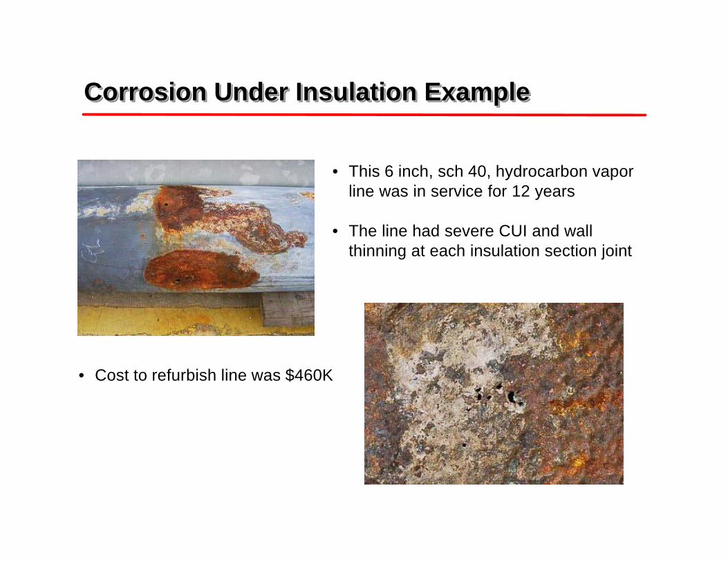
• This 6 inch, sch 40, hydrocarbon vaporline was in service for 12 years
• The line had severe CUI and wallthinning at each insulation section joint
• Cost to refurbish line was $460K
CUI Leak Data AnalysisCUI Leak Data AnalysisCUI Leak Data Analysis
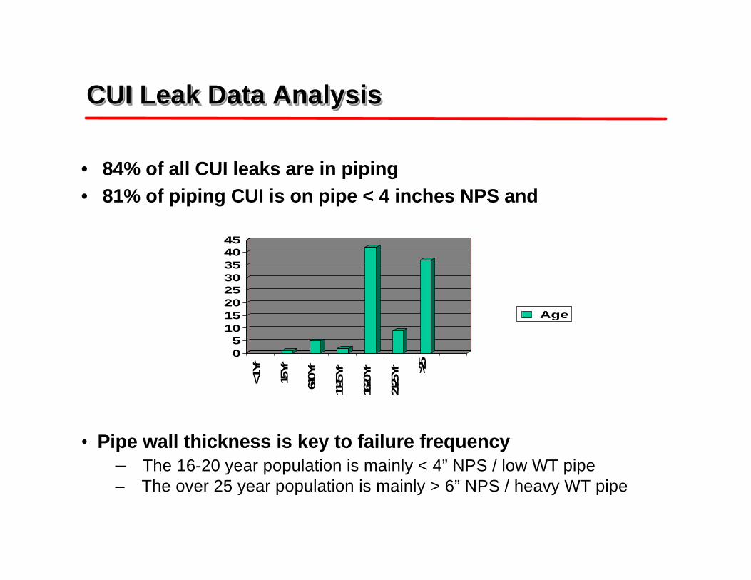
• 84% of all CUI leaks are in piping• 81% of piping CUI is on pipe < 4 inches NPS and
05
1015202530354045
< 1 Y
r
1-5 Yr
6-10 Y
r
11-15
Yr
16-20
Yr
21-25
Yr >25
Age
• Pipe wall thickness is key to failure frequency– The 16-20 year population is mainly < 4” NPS / low WT pipe– The over 25 year population is mainly > 6” NPS / heavy WT pipe
Maintenance Costs TodayMaintenance Costs TodayMaintenance Costs Today
Maintenance Cost by Equipment Type
Fixed Equipment35%
Machinery25%
Other15%
Instruments10%
Analyzers5%
Electrical7%
Pressure Relief3%
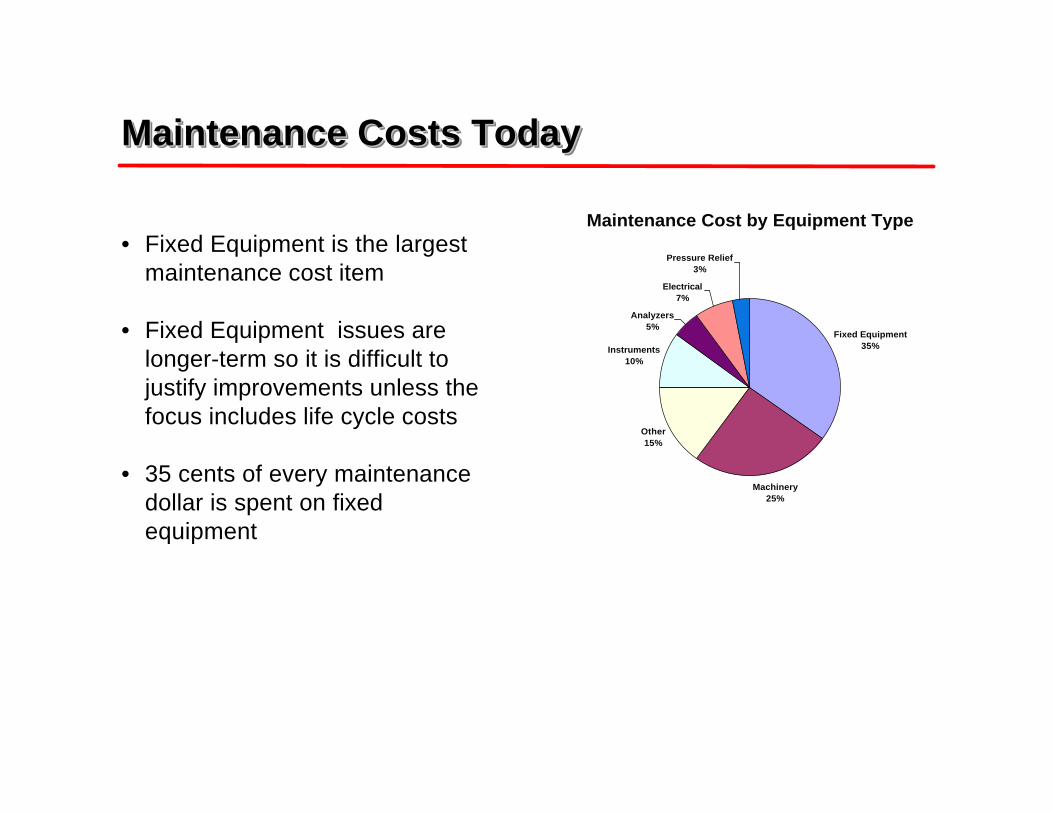
• Fixed Equipment is the largestmaintenance cost item
• Fixed Equipment issues arelonger-term so it is difficult tojustify improvements unless thefocus includes life cycle costs
• 35 cents of every maintenancedollar is spent on fixedequipment
Fixed Equipment Maintenance Costs TodayFixed Equipment Maintenance Costs TodayFixed Equipment Maintenance Costs Today
Fixed Equipment Maintenance Costs
Piping55%
Vessels & Tanks25%
Exchangers20%
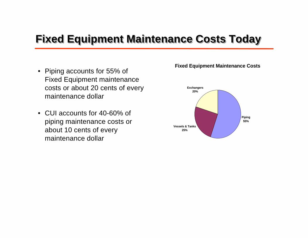
• Piping accounts for 55% ofFixed Equipment maintenancecosts or about 20 cents of everymaintenance dollar
• CUI accounts for 40-60% ofpiping maintenance costs orabout 10 cents of everymaintenance dollar
CUI Prevention Measures CUI Prevention MeasuresCUI Prevention Measures
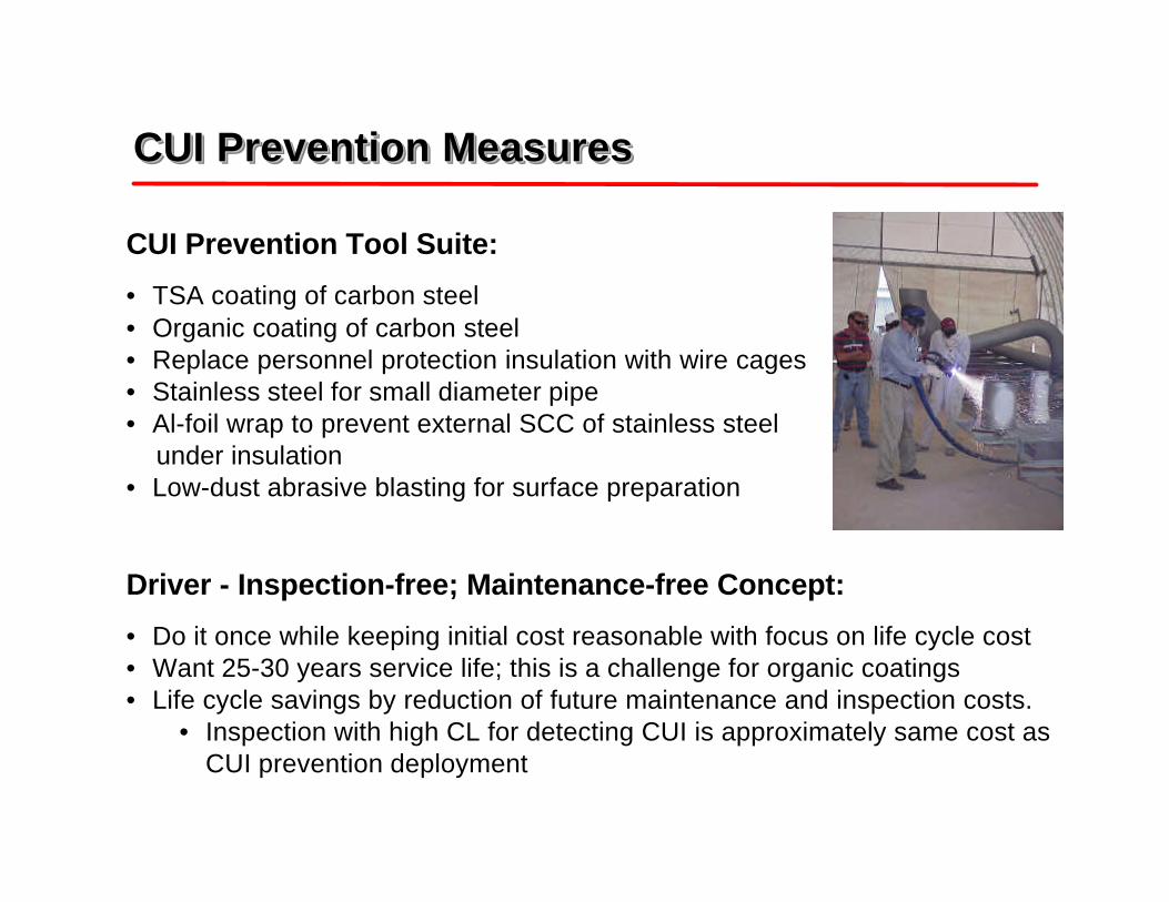
CUI Prevention Tool Suite:• TSA coating of carbon steel• Organic coating of carbon steel• Replace personnel protection insulation with wire cages• Stainless steel for small diameter pipe• Al-foil wrap to prevent external SCC of stainless steel under insulation• Low-dust abrasive blasting for surface preparation
Driver - Inspection-free; Maintenance-free Concept:
• Do it once while keeping initial cost reasonable with focus on life cycle cost• Want 25-30 years service life; this is a challenge for organic coatings• Life cycle savings by reduction of future maintenance and inspection costs.
• Inspection with high CL for detecting CUI is approximately same cost asCUI prevention deployment
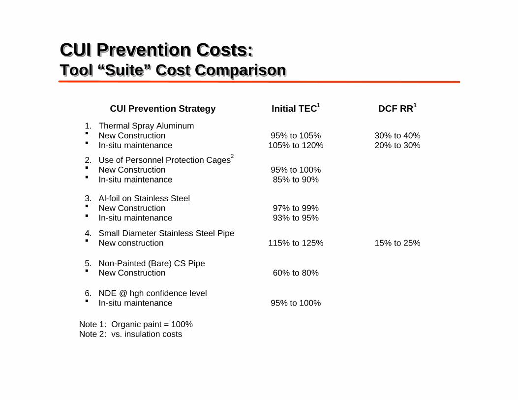
CUI Prevention Costs:Tool “Suite” Cost ComparisonCUI Prevention Costs:CUI Prevention Costs:Tool “Suite” Cost ComparisonTool “Suite” Cost Comparison
CUI Prevention Strategy Initial TEC1 DCF RR1
1. Thermal Spray Aluminum§ New Construction§ In-situ maintenance
95% to 105%105% to 120%
30% to 40%20% to 30%
2. Use of Personnel Protection Cages2
§ New Construction§ In-situ maintenance
95% to 100%85% to 90%
3. Al-foil on Stainless Steel§ New Construction§ In-situ maintenance
97% to 99%93% to 95%
4. Small Diameter Stainless Steel Pipe§ New construction 115% to 125% 15% to 25%
5. Non-Painted (Bare) CS Pipe§ New Construction 60% to 80%
6. NDE @ hgh confidence level§ In-situ maintenance 95% to 100%
Note 1: Organic paint = 100%Note 2: vs. insulation costs
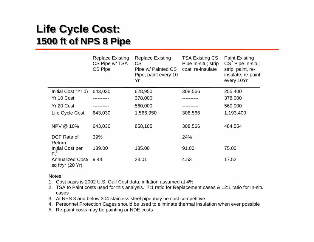
Life Cycle Cost:1500 ft of NPS 8 PipeLife Cycle Cost:Life Cycle Cost:1500 ft of NPS 8 Pipe1500 ft of NPS 8 Pipe
Replace ExistingCS Pipe w/ TSACS Pipe
Replace ExistingCS5
Pipe w/ Painted CSPipe; paint every 10Yr
TSA Existing CSPipe In-situ; stripcoat, re-insulate
Paint ExistingCS5 Pipe In-situ;strip, paint, re-insulate; re-paintevery 10Yr
Initial Cost (Yr 0) 643,030 628,950 308,566 255,400Yr 10 Cost ---------- 378,000 ---------- 378,000
Yr 20 Cost ---------- 560,000 ---------- 560,000Life Cycle Cost 643,030 1,566,950 308,566 1,193,400
NPV @ 10% 643,030 858,105 308,566 484,554
DCF Rate ofReturn
39% 24%
Initial Cost perFt
2189.00 185.00 91.00 75.00
Annualized Cost/sq ft/yr (20 Yr)
9.44 23.01 4.53 17.52
Notes:1. Cost basis is 2002 U.S. Gulf Cost data; inflation assumed at 4%2. TSA to Paint costs used for this analysis. 7:1 ratio for Replacement cases & 12:1 ratio for In-situ
cases3. At NPS 3 and below 304 stainless steel pipe may be cost competitive4. Personnel Protection Cages should be used to eliminate thermal insulation when ever possible5. Re-paint costs may be painting or NDE costs
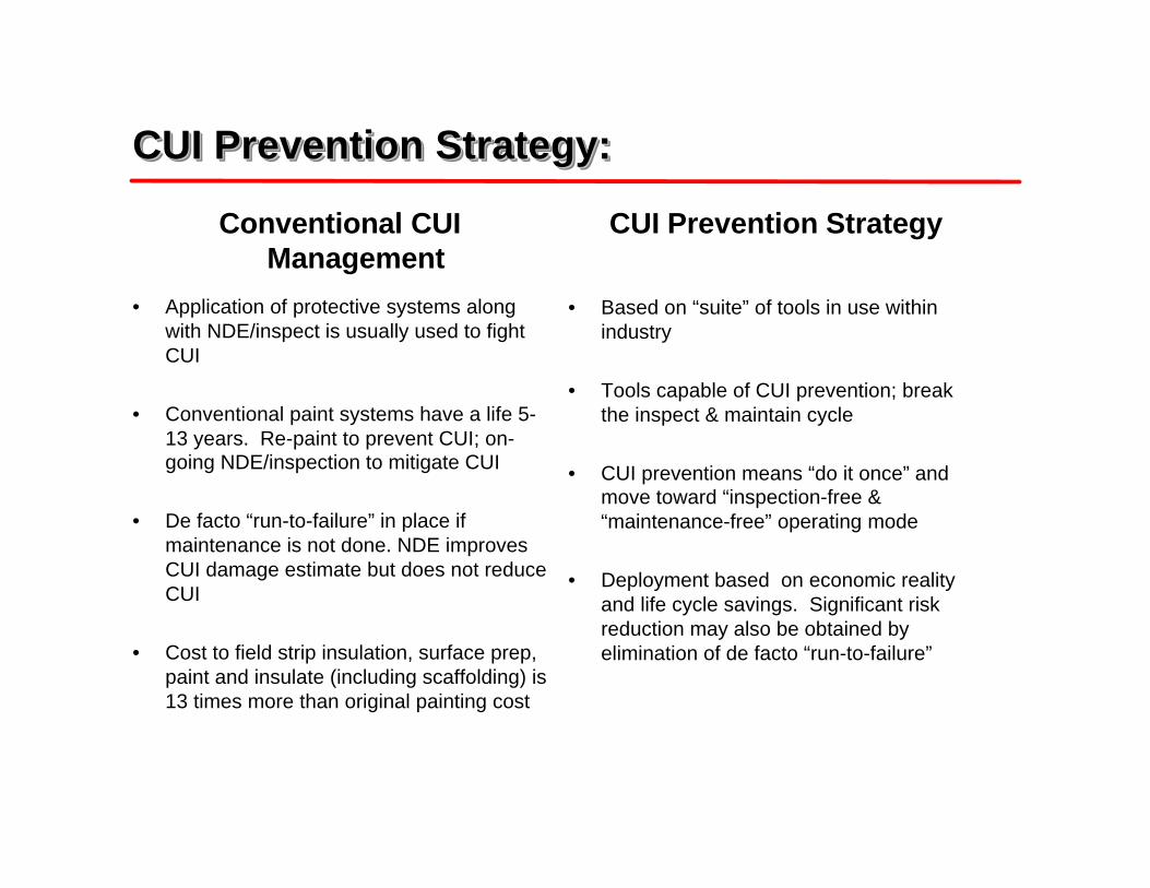
Conventional CUIManagement
• Application of protective systems alongwith NDE/inspect is usually used to fightCUI
• Conventional paint systems have a life 5-13 years. Re-paint to prevent CUI; on-going NDE/inspection to mitigate CUI
• De facto “run-to-failure” in place ifmaintenance is not done. NDE improvesCUI damage estimate but does not reduceCUI
• Cost to field strip insulation, surface prep,paint and insulate (including scaffolding) is13 times more than original painting cost
CUI Prevention Strategy:CUI Prevention Strategy:CUI Prevention Strategy:
CUI Prevention Strategy
• Based on “suite” of tools in use withinindustry
• Tools capable of CUI prevention; breakthe inspect & maintain cycle
• CUI prevention means “do it once” andmove toward “inspection-free &“maintenance-free” operating mode
• Deployment based on economic realityand life cycle savings. Significant riskreduction may also be obtained byelimination of de facto “run-to-failure”
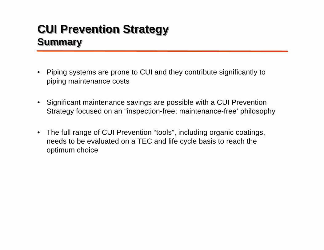
CUI Prevention StrategySummaryCUI Prevention StrategyCUI Prevention StrategySummarySummary
• Piping systems are prone to CUI and they contribute significantly topiping maintenance costs
• Significant maintenance savings are possible with a CUI PreventionStrategy focused on an “inspection-free; maintenance-free’ philosophy
• The full range of CUI Prevention “tools”, including organic coatings,needs to be evaluated on a TEC and life cycle basis to reach theoptimum choice
Minutes of EFC WP15 Corrosion in the Refinery Industry 30 September 2003
Appendix 5
Shell Risk Based Inspection Approach to
Corrosion under Insulation
Maarten Lorenz Shell Global Solutions
Shell Global Solutions
Shell Risk-Based Inspection Approachto Corrosion under Insulation
Presented by:Maarten Lorenz
Material & Inspection TechnologyShell Research & Technology Centre,
Amsterdam, The Netherlands
EFC WP15 September 2003© 2003 Shell Global Solutions International B.V.
Shell Global Solutions 2
EFC WP15 September 2003© 2003 Shell Global Solutions International B.V.
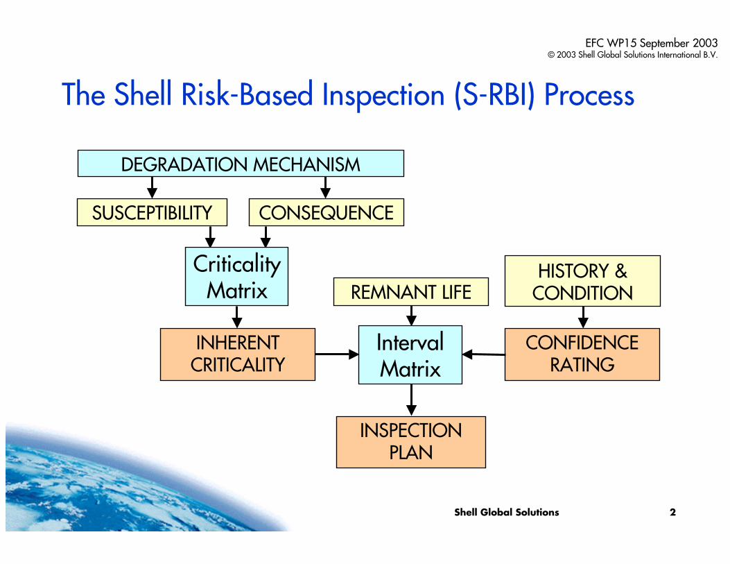
The Shell Risk-Based Inspection (S-RBI) Process
INHERENTCRITICALITY
CONFIDENCE RATING
INSPECTION PLAN
CONSEQUENCESUSCEPTIBILITY
Criticality Matrix
HISTORY & CONDITIONREMNANT LIFE
DEGRADATION MECHANISM
Interval Matrix
Shell Global Solutions 3
EFC WP15 September 2003© 2003 Shell Global Solutions International B.V.
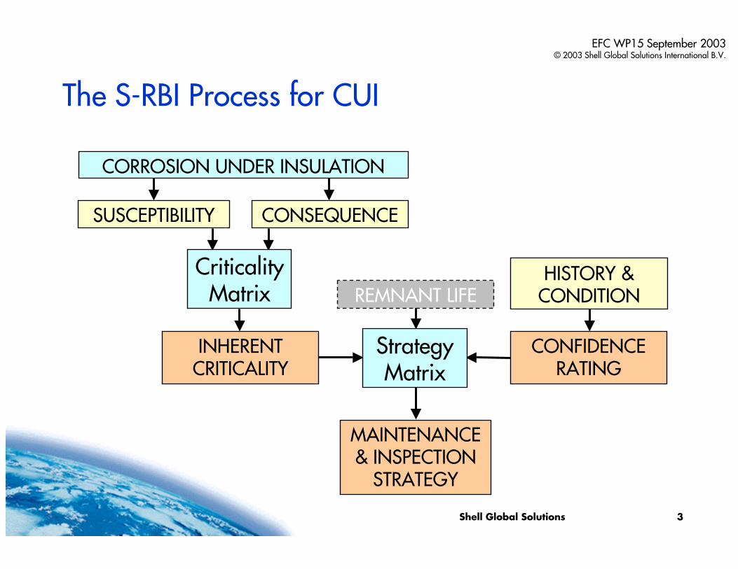
The S-RBI Process for CUI
INHERENTCRITICALITY
CONFIDENCE RATING
MAINTENANCE& INSPECTION
STRATEGY
CONSEQUENCESUSCEPTIBILITY
Criticality Matrix REMNANT LIFE
CORROSION UNDER INSULATION
Strategy Matrix
HISTORY & CONDITION
Shell Global Solutions 4
EFC WP15 September 2003© 2003 Shell Global Solutions International B.V.
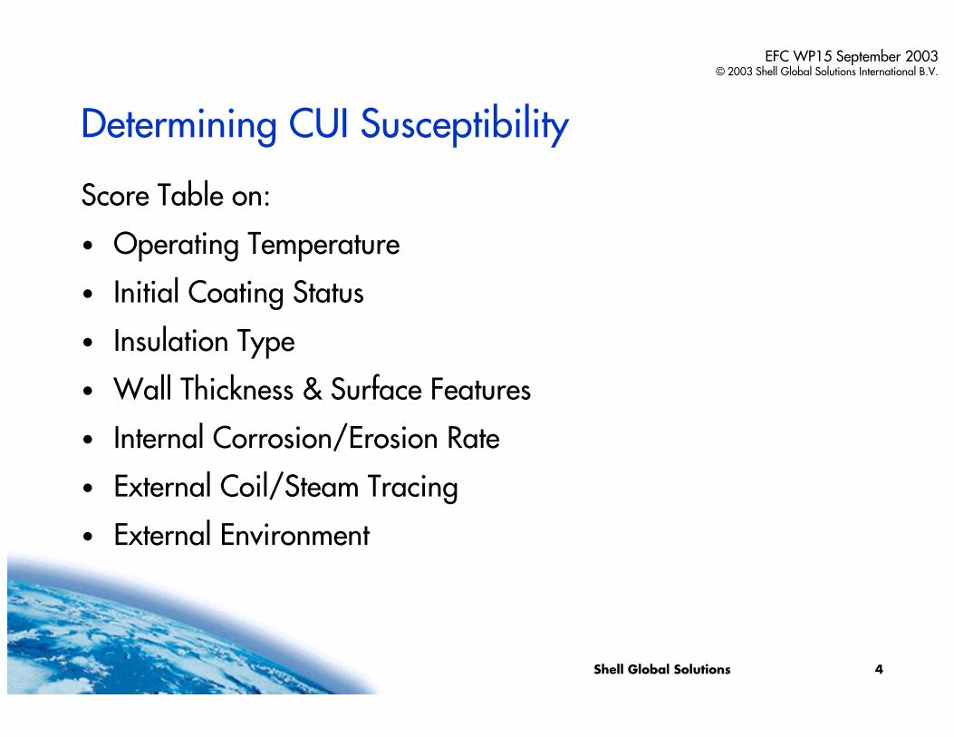
Determining CUI Susceptibility
Score Table on:
• Operating Temperature
• Initial Coating Status
• Insulation Type
• Wall Thickness & Surface Features
• Internal Corrosion/Erosion Rate
• External Coil/Steam Tracing
• External Environment
Shell Global Solutions 5
EFC WP15 September 2003© 2003 Shell Global Solutions International B.V.
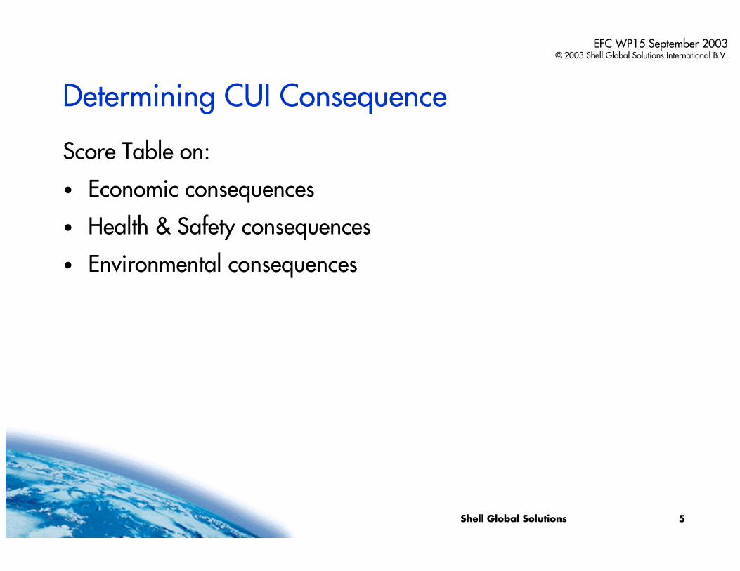
Determining CUI Consequence
Score Table on:
• Economic consequences
• Health & Safety consequences
• Environmental consequences
Shell Global Solutions 6
EFC WP15 September 2003© 2003 Shell Global Solutions International B.V.
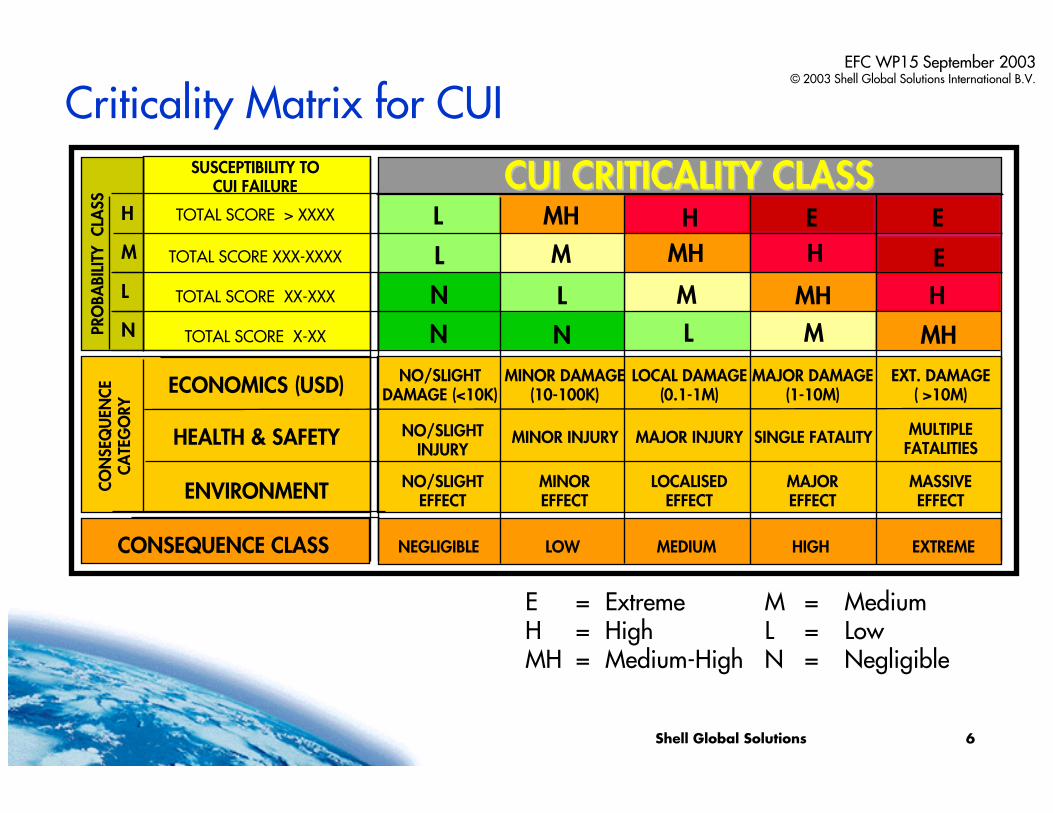
Criticality Matrix for CUI
E = Extreme M = MediumH = High L = LowMH = Medium-High N = Negligible
N L M
H
MH
EHMH
MHM
ML
L
N
N
EEHMHLM
L
N
H
PRO
BABI
LITY
CLA
SS
MULTIPLEFATALITIES
EXT. DAMAGE( >10M)
NO/SLIGHTINJURY
NO/SLIGHTDAMAGE (<10K)
NO/SLIGHTEFFECT
MINOR INJURY
MINOR DAMAGE(10-100K)
MINOREFFECT
MAJOR INJURY
LOCAL DAMAGE(0.1-1M)
LOCALISEDEFFECT
SINGLE FATALITY
MAJOR DAMAGE(1-10M)
MAJOREFFECT
MASSIVEEFFECT
HEALTH & SAFETY
ECONOMICS (USD)
ENVIRONMENTCON
SEQ
UEN
CECA
TEG
ORY
CONSEQUENCE CLASS NEGLIGIBLE LOW MEDIUM HIGH EXTREME
TOTAL SCORE > XXXX
SUSCEPTIBILITY TOCUI FAILURE CUI CRITICALITY CLASSCUI CRITICALITY CLASS
TOTAL SCORE XXX-XXXX
TOTAL SCORE XX-XXX
TOTAL SCORE X-XX
Shell Global Solutions 7
EFC WP15 September 2003© 2003 Shell Global Solutions International B.V.
Confidence Rating
An item’s criticality basically determines the inspection/maintenance strategy to be applied.
Depending on how well the condition of an item is known, a limited degree of conservatism/opportunism is applied in choosing the inspection/maintenance strategy.
CUI Confidence Rating depends on:
• cladding & insulation condition
• number & quality of CUI inspections
• knowledge of CUI promoting conditions
Shell Global Solutions 8
EFC WP15 September 2003© 2003 Shell Global Solutions International B.V.
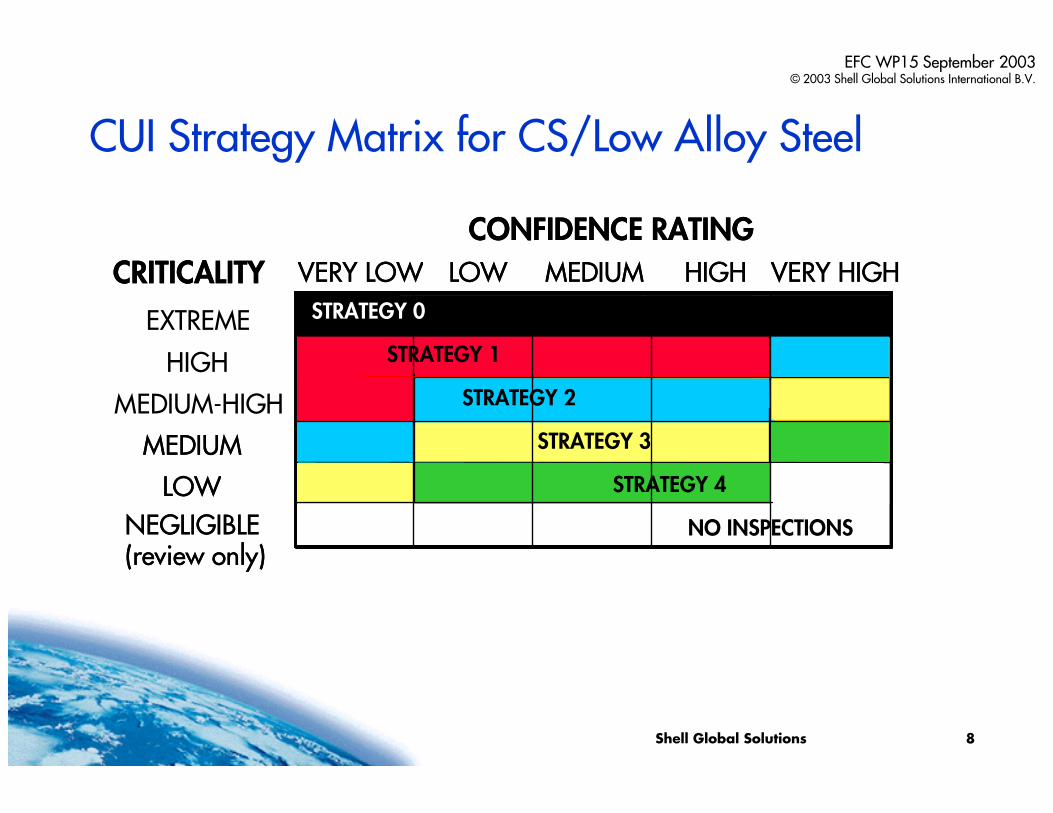
CUI Strategy Matrix for CS/Low Alloy Steel
CONFIDENCE RATING
VERY LOW LOW MEDIUM HIGH VERY HIGHCRITICALITY
HIGH
MEDIUM-HIGH
MEDIUM
LOW
STRATEGY 2 STRATEGY 3
NEGLIGIBLE (review only)
EXTREME
NO INSPECTIONS
STRATEGY 1
CONFIDENCE RATING
VERY LOW LOW MEDIUM HIGH VERY HIGHCRITICALITY
MEDIUM
LOW
STRATEGY 3
NEGLIGIBLE (review only)
STRATEGY 0
STRATEGY 1
STRATEGY 2
STRATEGY 3
STRATEGY 4
NO INSPECTIONS
Shell Global Solutions 9
EFC WP15 September 2003© 2003 Shell Global Solutions International B.V.
CUI Inspection/Maintenance Strategies
• Effectively five strategies have been developed for the six criticality levels.
• The coverage and quality of the applied coating/paint may add up to 8 years of CUI protection.
• Inspection intervals start at the moment the coating/paint protection has ended.
• Inspection intervals are based on recommended maximum timing.
• Initial inspection actions always involve delagging.
• Inspection results may lead to adjusting the strategy level.
Shell Global Solutions 10
EFC WP15 September 2003© 2003 Shell Global Solutions International B.V.
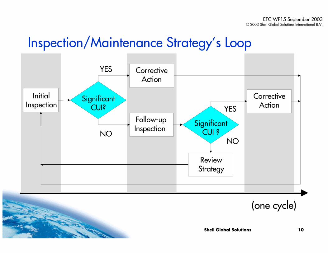
Inspection/Maintenance Strategy’s Loop
NO
YES
NO
YES
(one cycle)
InitialInspection
SignificantCUI?
Follow-upInspection
SignificantCUI ?
CorrectiveAction
CorrectiveAction
ReviewStrategy
Shell Global Solutions 11
EFC WP15 September 2003© 2003 Shell Global Solutions International B.V.
CUI Inspection/Maintenance Plan:
… requires pre-screening of the assets prior to application(not applied to items with negligible susceptibility to CUI).
… does not rely too much on non-intrusive inspection results(screening inspection techniques used to indicate susceptible areas).
… is harmonised with the S-RBI methodology.
Shell Global Solutions 12
EFC WP15 September 2003© 2003 Shell Global Solutions International B.V.
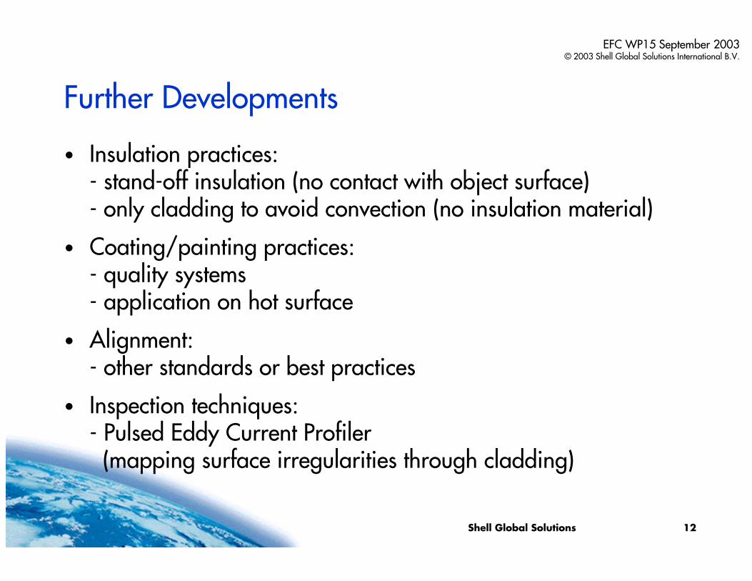
Further Developments
• Insulation practices:- stand-off insulation (no contact with object surface)- only cladding to avoid convection (no insulation material)
• Coating/painting practices:- quality systems- application on hot surface
• Alignment:- other standards or best practices
• Inspection techniques:- Pulsed Eddy Current Profiler(mapping surface irregularities through cladding)

Shell Global Solutions
Shell Risk-Based Inspection Approachto Corrosion under Insulation
- thank you for your attention -ANY QUESTIONS OR REMARKS?
Presented by:Maarten Lorenz
Material & Inspection TechnologyShell Research & Technology Centre
Amsterdam, The [email protected]
EFC WP15 September 2003© 2003 Shell Global Solutions International B.V.
Minutes of EFC WP15 Corrosion in the Refinery Industry 30 September 2003
Appendix 6
Structure-Activity Relationships in
series of Corrosion Inhibitors
I. Lukovits Chem. Res. Center Budapest
EFC Working Party 15
I. LukovitsI. LukovitsChemChem. . ResRes. . CenterCenter
H-1525 Budapest, POB 17H-1525 Budapest, POB 17HungaryHungary
EFC Working Party 15
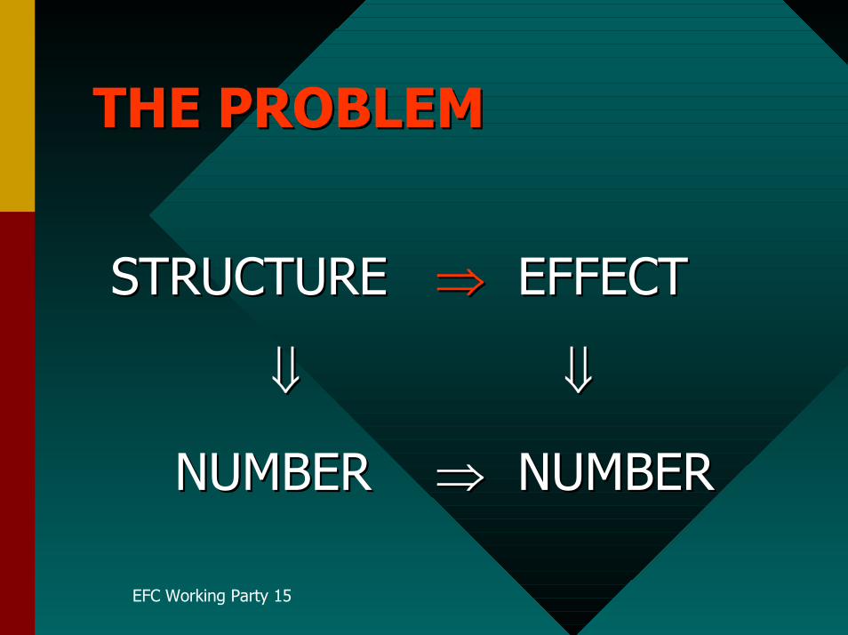
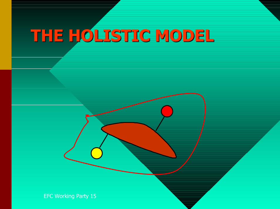
STRUCTURE STRUCTURE �� EFFECT EFFECT
�� ��
NUMBER NUMBER �� NUMBER NUMBER
EFC Working Party 15
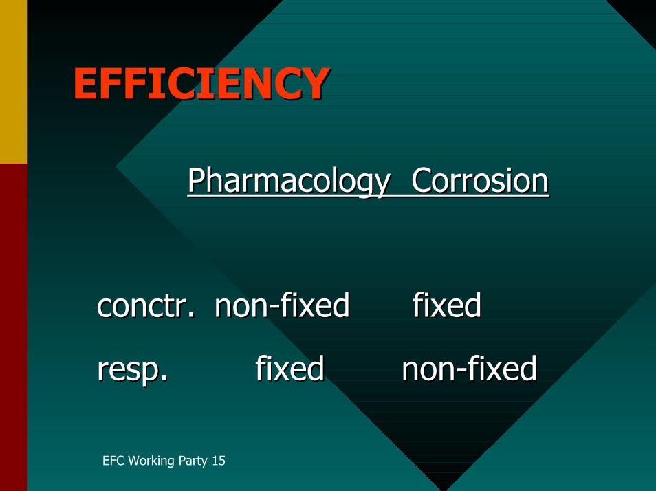
Pharmacology CorrosionPharmacology Corrosion
conctrconctr.. non-fixed fixed non-fixed fixed
respresp.. fixed fixed non-fixednon-fixed
EFC Working Party 15
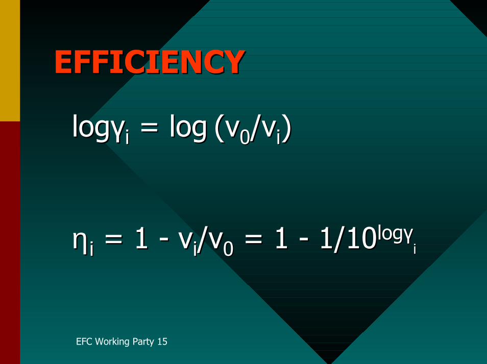
loglogγγii = = loglog (v(v00//vvii))
ηη ii = 1 - = 1 - v vii/v/v00 = 1 - 1/10 = 1 - 1/10loglogγγii
EFC Working Party 15
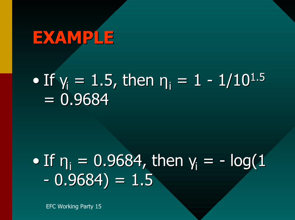
•• IfIf γγii = 1.5, = 1.5, then then ηη ii = 1 - 1/10 = 1 - 1/101.51.5
= 0.9684= 0.9684
•• IfIf ηη ii = 0.9684, = 0.9684, then then γγii = - = - log log(1(1- 0.9684) = 1.5- 0.9684) = 1.5

EFC Working Party 15

EFC Working Party 15
EFC Working Party 15
EFC Working Party 15
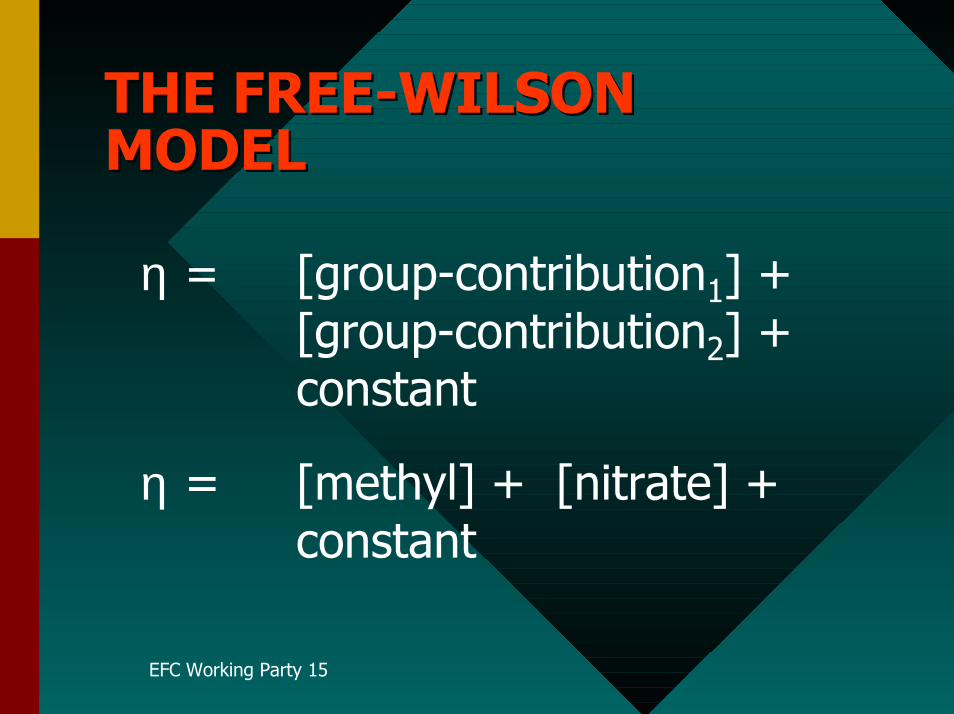
η = [group-contribution1] + [group-contribution2] +
constant
η = [methyl] + [nitrate] + constant
EFC Working Party 15
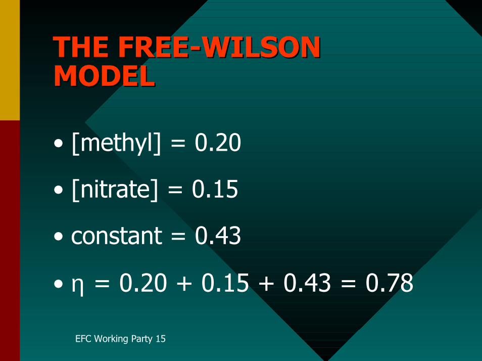
• [methyl] = 0.20
• [nitrate] = 0.15
• constant = 0.43
• η = 0.20 + 0.15 + 0.43 = 0.78
EFC Working Party 15
•Dupin, P., DeSavignac, A. andLattes, A., Werkstoffe u.Korrosion, (1982) 33, 203.
••DupinDupin, P.,, P., Vilovia Vilovia-- Vera, D.A, deVera, D.A, deSavignacSavignac, A.,, A., Lattes Lattes, A., A. and andHaicourHaicour, P., , P., SEIC, 1980SEIC, 1980
••Kálmán, E., Lukovits, I., Kármán,Kálmán, E., Lukovits, I., Kármán,F. H.F. H. and Telegdi and Telegdi,, J., J.,EUROCORR’91, 1991EUROCORR’91, 1991
EFC Working Party 15
η = aπ + bσ + constant
EFC Working Party 15
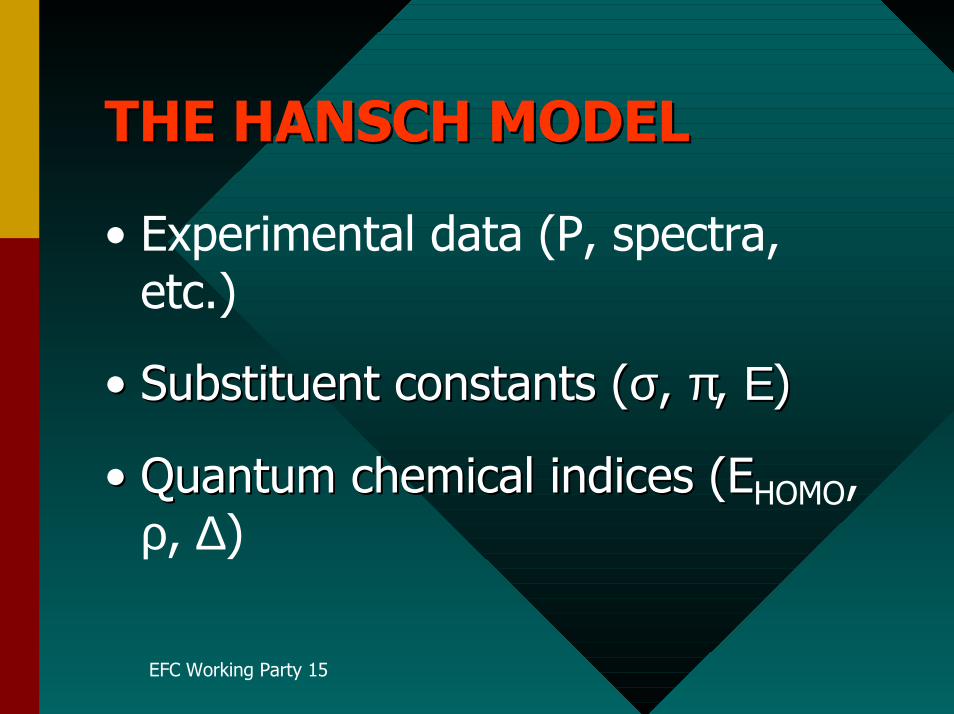
• Experimental data (P, spectra,etc.)
•• SubstituentSubstituent constants ( constants (σσ, , ππ, , ΕΕ))
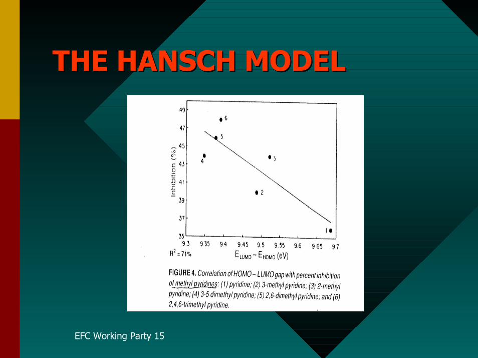
•• Quantum chemical indices (EQuantum chemical indices (EHOMO,ρ, ∆)
EFC Working Party 15
EFC Working Party 15
EFC Working Party 15
I. Lukovits, E.I. Lukovits, E. Kálmán Kálmán, F., F. Zucchi Zucchi:: Corrosion 57, 3-8 (2001).Corrosion 57, 3-8 (2001).
EFC Working Party 15
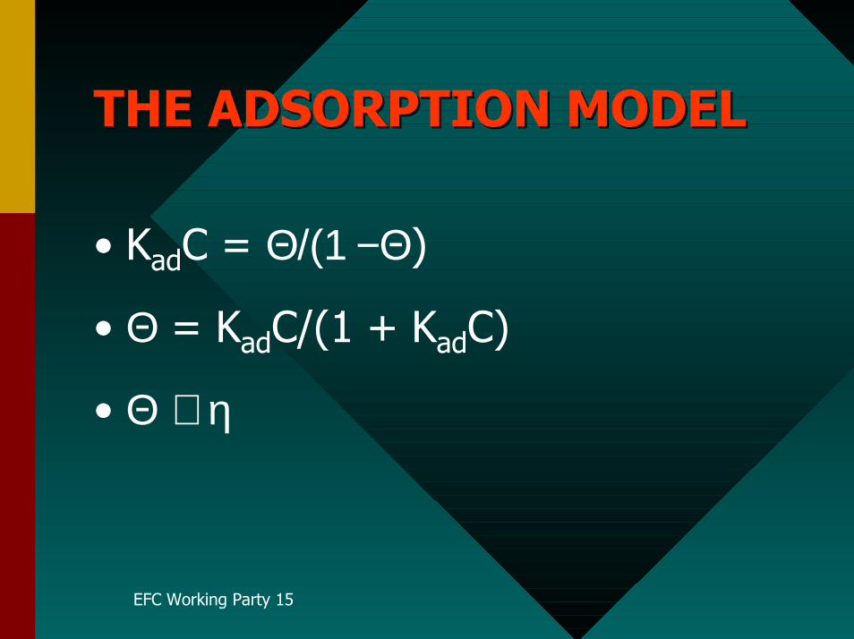
• KadC = Θ/(1 −Θ)
• Θ = KadC/(1 + KadC)
• Θ ≅ η
EFC Working Party 15
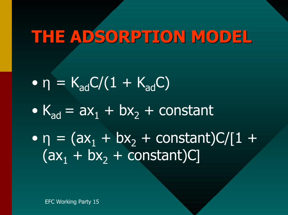
• η = KadC/(1 + KadC)
• Kad = ax1 + bx2 + constant
• η = (ax1 + bx2 + constant)C/[1 +(ax1 + bx2 + constant)C]
EFC Working Party 15
EFC Working Party 15
I. Lukovits, K. Pálfi, I. Bakó and E.Kálmán:
Corrosion 53, 915-919 (1997).
EFC Working Party 15
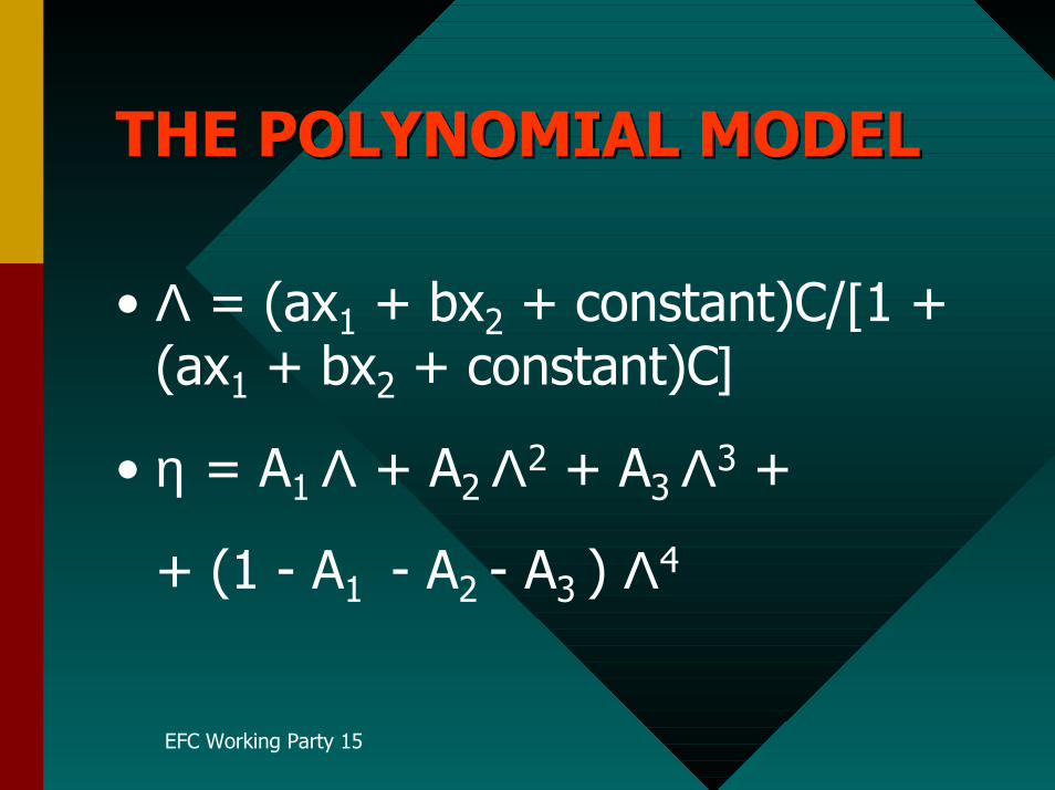
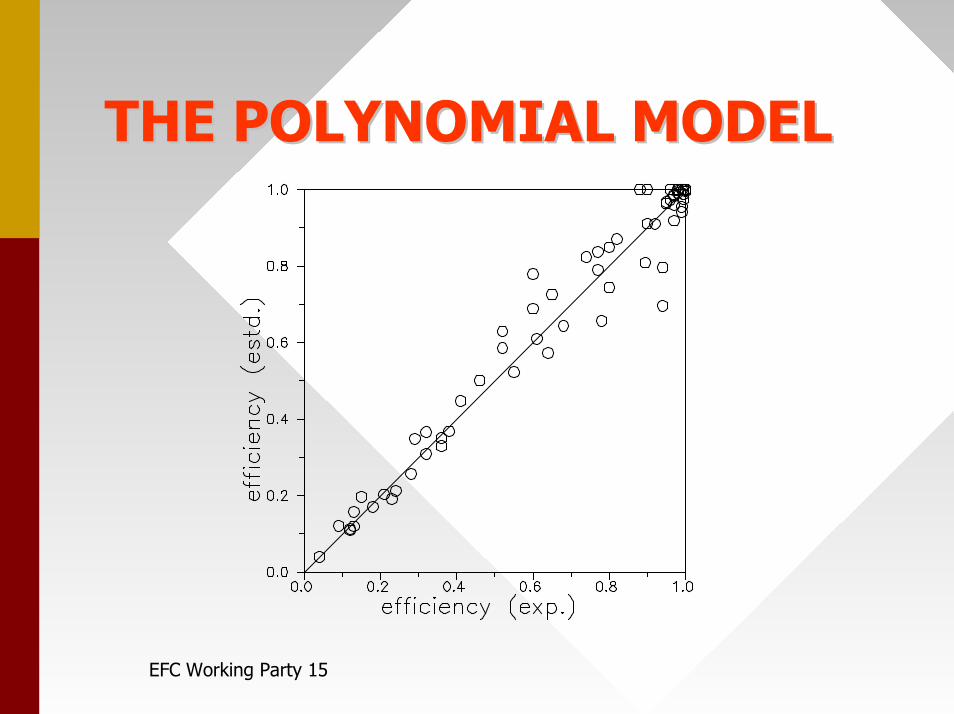
• Λ = (ax1 + bx2 + constant)C/[1 +(ax1 + bx2 + constant)C]
• η = A1 Λ + A2 Λ2 + A3 Λ3 +
+ (1 - A1 - A2 - A3 ) Λ4
EFC Working Party 15
EFC Working Party 15
I. Lukovits, I. Bakó, A. Shabanand E. Kálmán.
Electrochim. Acta 43, 131-136(1998).
EFC Working Party 15
W. Durnie, R. Demarco, A.Jefferson, B. Kinsella,J.Electrochem.Soc., 146,1751(1999).
EFC Working Party 15
QSAR may be an effective tool inQSAR may be an effective tool inselecting new, possibly efficient,selecting new, possibly efficient,compounds and in discardingcompounds and in discardinginactive compounds inactive compounds withoutwithoutadditionaladditional experimental efforts. experimental efforts.
EFC Working Party 15
•• OTKA T034983 & T035122OTKA T034983 & T035122
•• Prof. F. ZUCCHI (Prof. F. ZUCCHI (FerraraFerrara,, Italy Italy))and and Prof. M. Prof. M. Lagrenée Lagrenée ((LilleLille))
•• YOUYOU
Minutes of EFC WP15 Corrosion in the Refinery Industry 30 September 2003
Appendix 7
Flow Induced Stress Corrosion Failure
of SS Piping
Joanna Hucinska Gansk University of
Technology
FLOW-INDUCED STRESS CORROSION FAILUREOF SS PIPING
Joanna HucińskaGdańsk University of Technology
Gdańsk, Poland
EFC WP 15 MEETINGEUROCORR 2003, BUDAPEST
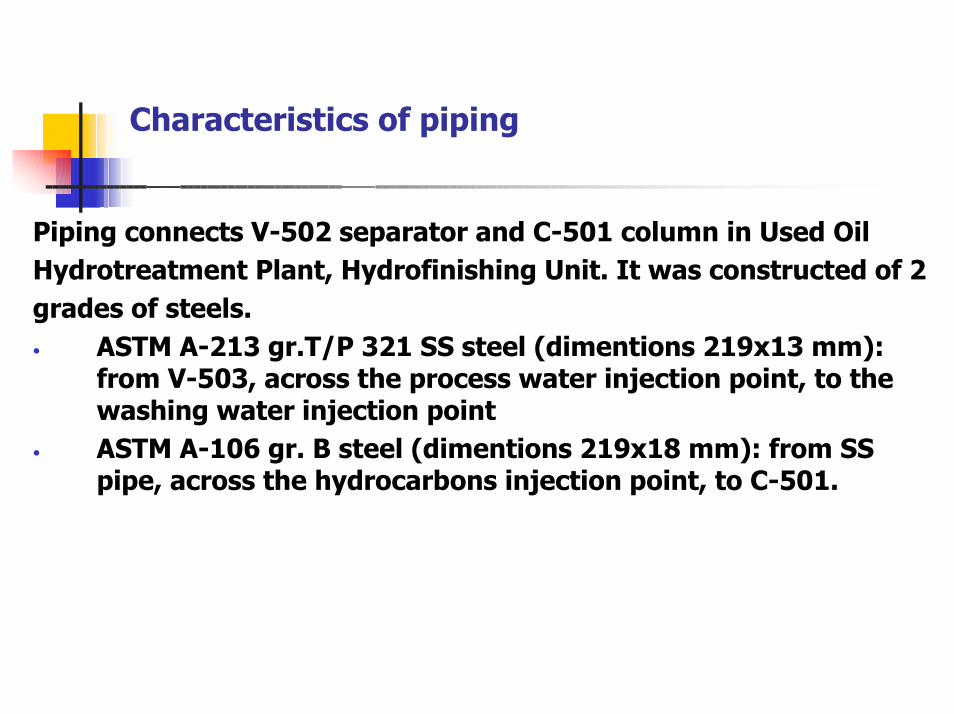
Characteristics of piping
Piping connects V-502 separator and C-501 column in Used OilHydrotreatment Plant, Hydrofinishing Unit. It was constructed of 2grades of steels.• ASTM A-213 gr.T/P 321 SS steel (dimentions 219x13 mm):
from V-503, across the process water injection point, to thewashing water injection point
• ASTM A-106 gr. B steel (dimentions 219x18 mm): from SSpipe, across the hydrocarbons injection point, to C-501.
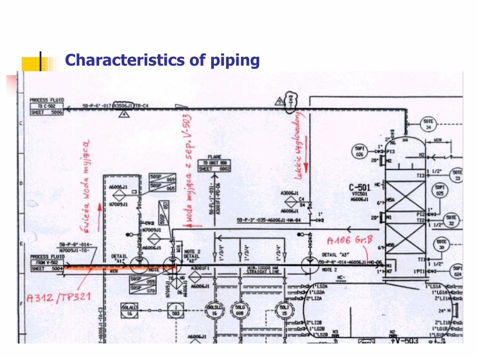
Characteristics of piping
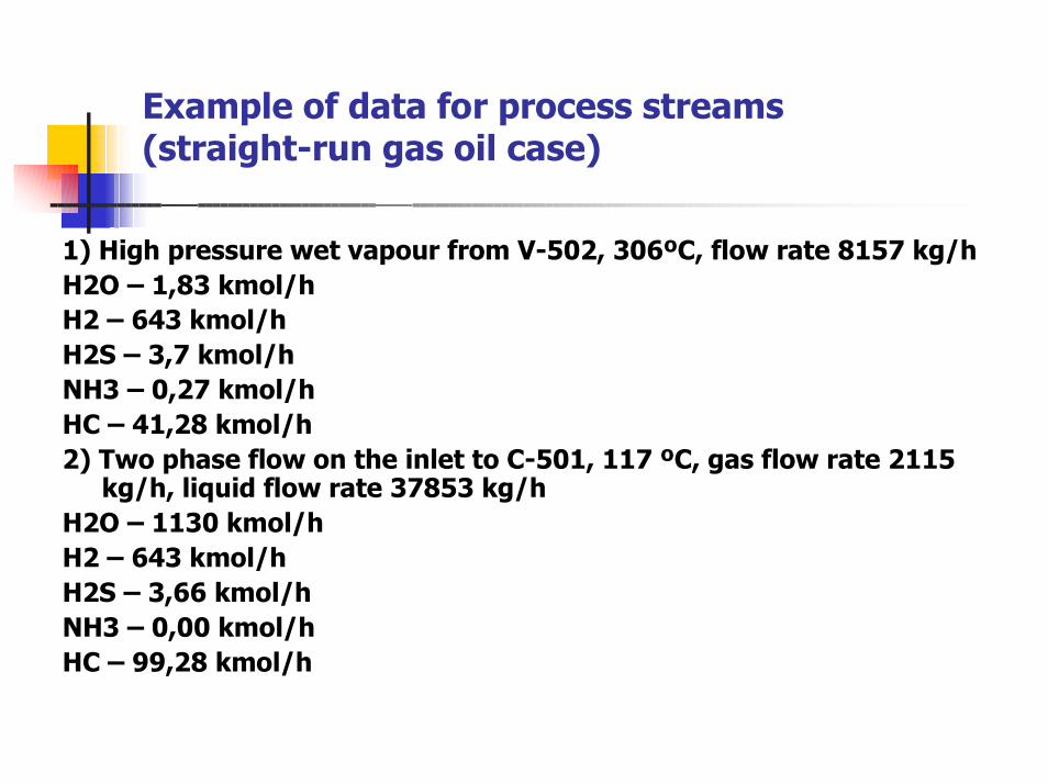
Example of data for process streams(straight-run gas oil case)
1) High pressure wet vapour from V-502, 306ºC, flow rate 8157 kg/hH2O – 1,83 kmol/hH2 – 643 kmol/hH2S – 3,7 kmol/hNH3 – 0,27 kmol/hHC – 41,28 kmol/h2) Two phase flow on the inlet to C-501, 117 ºC, gas flow rate 2115
kg/h, liquid flow rate 37853 kg/hH2O – 1130 kmol/hH2 – 643 kmol/hH2S – 3,66 kmol/hNH3 – 0,00 kmol/hHC – 99,28 kmol/h
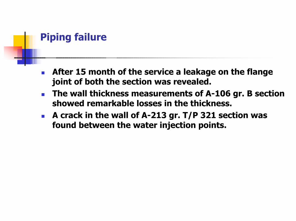
Piping failure
� After 15 month of the service a leakage on the flangejoint of both the section was revealed.
� The wall thickness measurements of A-106 gr. B sectionshowed remarkable losses in the thickness.
� A crack in the wall of A-213 gr. T/P 321 section wasfound between the water injection points.
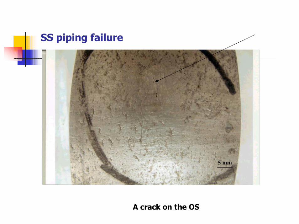
SS piping failure
A crack on the OS
5 mm
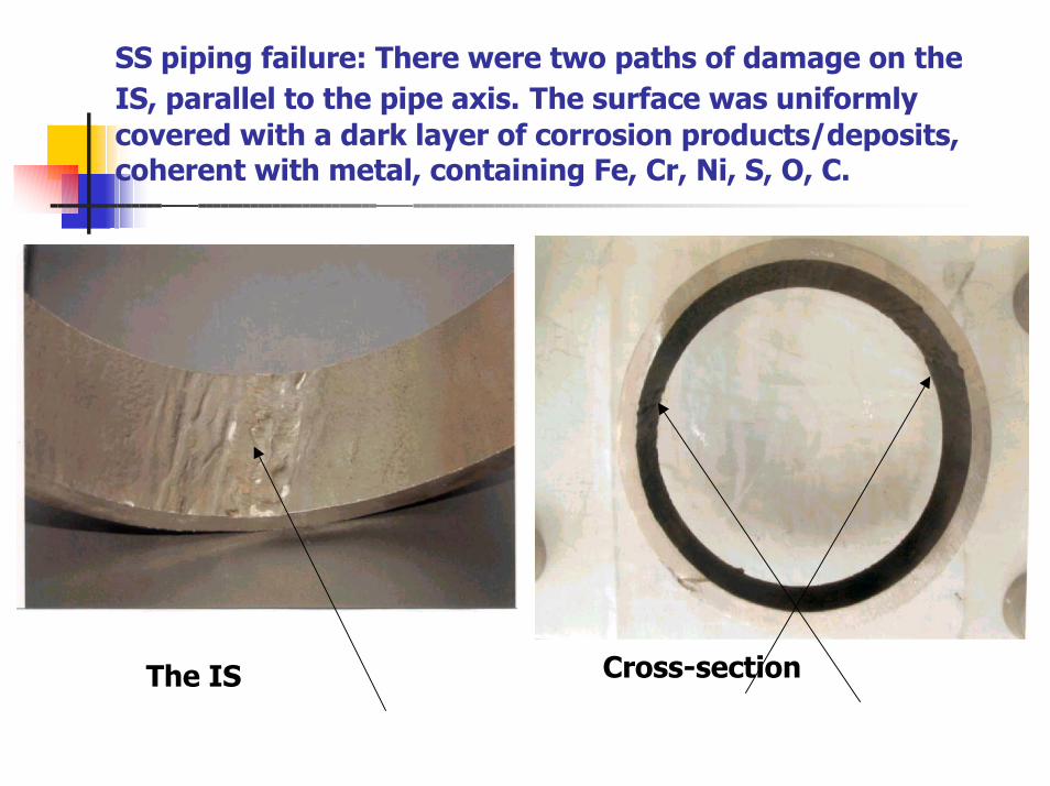
SS piping failure: There were two paths of damage on theIS, parallel to the pipe axis. The surface was uniformlycovered with a dark layer of corrosion products/deposits,coherent with metal, containing Fe, Cr, Ni, S, O, C.
The IS Cross-section
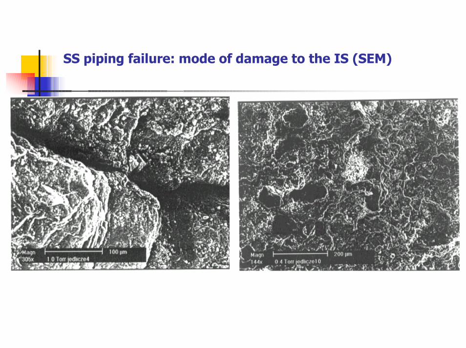
SS piping failure: mode of damage to the IS (SEM)
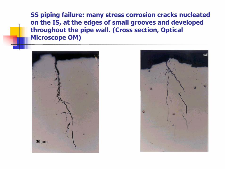
SS piping failure: many stress corrosion cracks nucleatedon the IS, at the edges of small grooves and developedthroughout the pipe wall. (Cross section, OpticalMicroscope OM)
30 µm
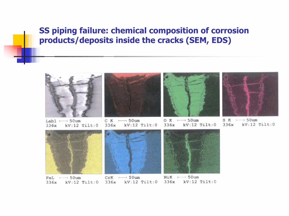
SS piping failure: chemical composition of corrosionproducts/deposits inside the cracks (SEM, EDS)
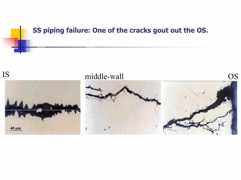
SS piping failure: One of the cracks gout out the OS.
40 µm
IS middle-wall OS
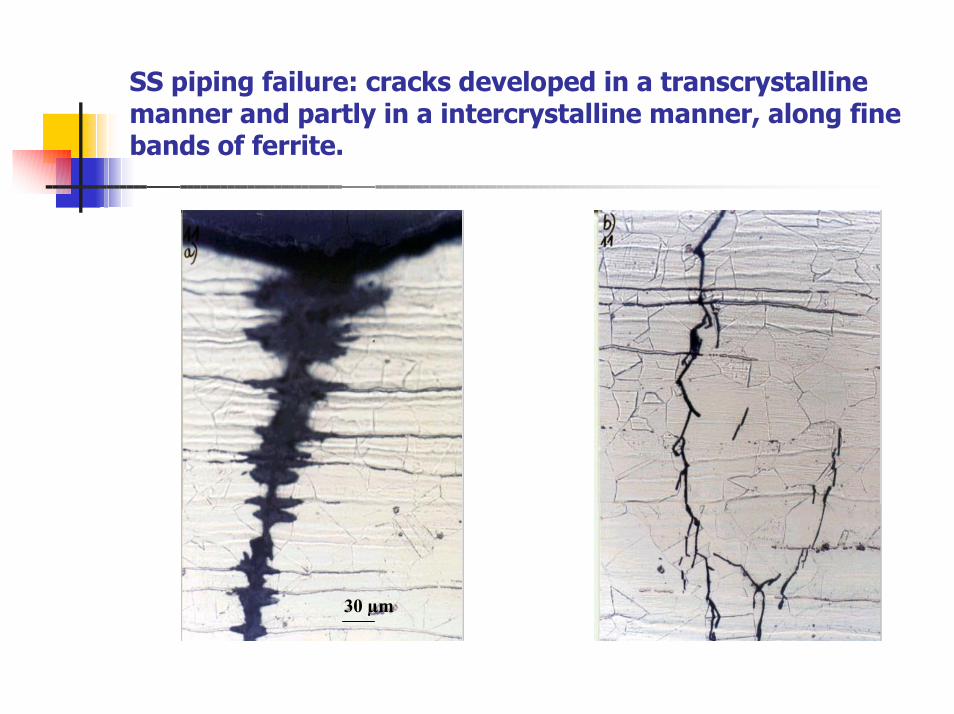
SS piping failure: cracks developed in a transcrystallinemanner and partly in a intercrystalline manner, along finebands of ferrite.
30 µm
Reasons of piping failure
• The crack detected on the OS of SS piping was causedby through-thickness SCC.
• Due to remarkable turbulence of flow and resultingdynamic impacts of droplets/jets/pressure waves, theIS was plastically deformed and strengthen to a statein which fine cracks initiated along surface notches.
• The presence of hydrogen sulphide and other sulphurcompounds have principal meaning for thedevelopment of the cracks.