Embed Size (px)
Citation preview
Appendix 1: Tables
by K. Piihlandt
A.1.1 Standards for Formability Testing
This list (update December 1997) includes many standards which have not been cited in the above text. Among the ASTM standards those based on the metric system have been preferred. Standards concerning the testing facilities have not been included. For special testing methods for tubes see ISO 8491 to 8496.
Tension Testing
3.6 EN 10002-1: Metallic materials - tensile testing - Pt. I: Method of test (at ambient temperature), 1991 (see also prEN 10002-1, 1998).
EN 10002 - 5: Metallic materials - tensile testing - Pt. 5: Method of test at elevated temperatures, 1992.
3.5 ASTM E 8 M-99: Standard test methods for tension testing of metallic materials (metric)
ASTM E 21-92 (Reapproved 1998): Standard test methods for elevated temperature tension testing of metallic materials.
ASTM A 370-97a: Standard methods and definitions for mechanical testing of steel products.
ASTM B 557M-94: Standard methods of tension testing wrought and cast aluminum- and magnesium products (metric).
3.13 ASTM E 646-98: Standard test methods for tensile strain-hardening exponents (nvalues) of metallic sheet materials.
ASTM E 345-93 (Reapproved 1998): Standard test methods for tension testing of metallic foil.
ASTM E 517-98: Standard test method for plastic strain ratio r for sheet metal.
304 Appendix 1: Tables
ISO 10113: Metallic materials; sheet and strip; determination of plastic strain ratio, 1991.
ISO 10275: Metallic materials; sheet and strip; determination of tensile strain hardening exponent, 1993.
ISO 6892: Metallic materials - tensile testing at ambient temperature, 1998.
ISOIDIS 783: Metallic materials - tensile testing at elevated temperatures, 1997.
ISOIDIS 15579: Metallic materials - tensile testing at low temperature, 1998.
Other Methods of Determining Flow Curves
3.25 ASTM E 209-65 (Reapproved 1993): Standard test methods for compression testing of metallic material at elevated temperatures with conventional or rapid heating rates and strain rates.
ASTM E 9-89a (Reapproved 1995): Standard test methods for compression testing of metallic materials at room temperature.
Stahl-Eisen-Priitblatt 1123: Cold upsetting test for determining the strain-hardening behavior (in German), 2nd edn, 1986.
Ductility and Formability (Workability) Testing
ASTM E 643-84 (Reapproved 1995): Standard test method for ball punch deformation of metallic sheet material.
5.55 ASTM E 290-97a: Standard test method for bend testing of material for ductility.
3.120 ASTM A 938-97: Standard test method for torsion testing of wire.
3.121 ASTM E 23-98: Methods for notched bar impast testing of metallic materials.
ISO 8490: Metallic materials - sheet and strip - modified Erichsen cupping test, 1986.
ISO 7438: Metallic materials - bend test, 1985.
ISO 7799: Metallic materials - sheet and strip 3 mm thick and less - reverse bend test, 1985.
ISO 7800: Metallic materials; wire; simple torsion test, 1984.
ISO 7801: Metallic materials; wire; reverse bend test, 1984.
A.l.l Standards for Formability Testing 305
ISO 9649: Metallic materials; wire; reverse torsion test, 1990.
ISO 12004: Metallic materials - guidelines for the determination of forming limit diagrams, 1997.
ISOITR 14936: Metallic materials - strain analysis report, 1998.
Specimen Preparation
3.100 ISO 377: Steel and steel products. Location and preparation of samples and test pieces for mechanical testing, 1997 (see also ISO 377, Technical corrigendum 1, 1997).
ISO-DIS 3785: Metallic materials - designation of test piece axis, 1995.
Symbols and Definitions
ISO/TR 12735-1: Mechanical testing of metals - symbols used with their definitions - Pt. 1: Symbols and definitions in published standards, 1996.
ISO/TR 12735-2: Mechanical testing of metals - symbols used with their definitions- Pt. 2: Recommendations for the development of symbols and definitions, 1996.
ASTM E 6-98: Standard terminology relating to methods of mechanical testing.
306 Appendix 1: Tables
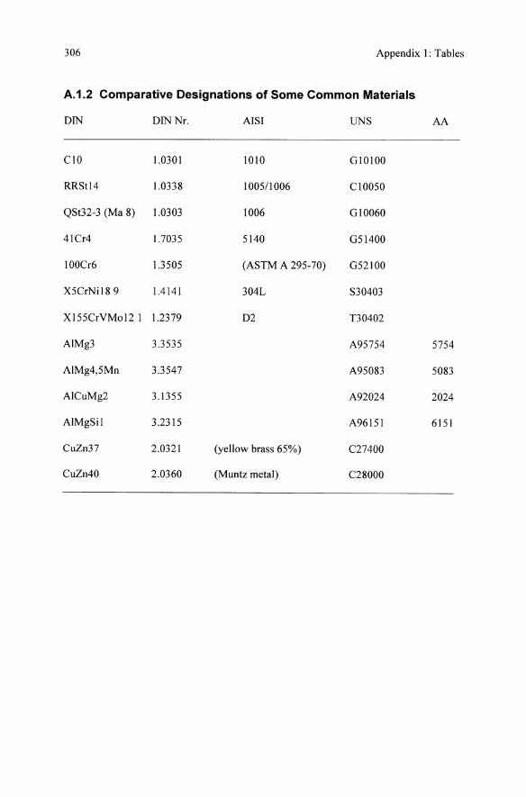
A.1.2 Comparative Designations of Some Common Materials
DIN DIN Nr. AISI UNS AA
CIO 1.0301 1010 GI0lO0
RRSt14 1.0338 100511006 CI0050
QSt32-3 (Ma 8) 1.0303 1006 GI0060
41Cr4 1.7035 5140 G51400
100Cr6 1.3505 (ASTM A 295-70) G52100
X5CrNi189 1.4141 304L S30403
X155CrVMo12 1 1.2379 D2 T30402
AlMg3 3.3535 A95754 5754
AlMg4,5Mn 3.3547 A95083 5083
AICuMg2 3.1355 A92024 2024
AlMgSil 3.2315 A96151 6151
CuZn37 2.0321 (yellow brass 65%) C27400
CuZn40 2.0360 (Muntz metal) C28000
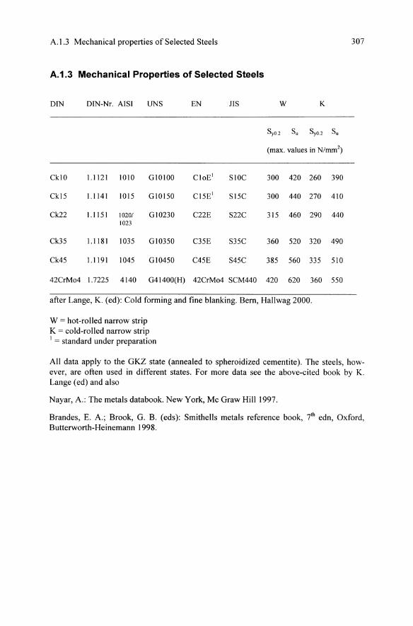
A.l.3 Mechanical properties of Selected Steels
A.1.3 Mechanical Properties of Selected Steels
DIN DIN-Nr. AISI UNS EN JIS W K
SyO.2 Su SyO.2 Su
(max. values in N/mm2)
CklO 1.1121 1010 GlOIOO CloE) SIOC 300 420 260 390
Ckl5 1.1141 1015 GlO150 CI5E) S15C 300 440 270 410
Ck22 1.1151 10201 GI0230 C22E S22C 315 460 290 440 1023
Ck35 1.1181 1035 Gl0350 C35E S35C 360 520 320 490
Ck45 1.1191 1045 Gl0450 C45E S45C 385 560 335 510
42CrMo4 1.7225 4140 G41400(H) 42CrMo4 SCM440 420 620 360 550
after Lange, K. (ed): Cold forming and fine blanking. Bern, Hallwag 2000.
W = hot-rolled narrow strip K = cold-rolled narrow strip ) = standard under preparation
307
All data apply to the GKZ state (annealed to spheroidized cementite). The steels, however, are often used in different states. For more data see the above-cited book by K. Lange (ed) and also
Nayar, A.: The metals databook. New York, Mc Graw Hill 1997.
Brandes, E. A.; Brook, G. B. (eds): Smithells metals reference book, 7th edn, Oxford, Butterworth-Heinemann 1998.
308 Appendix I: Tables
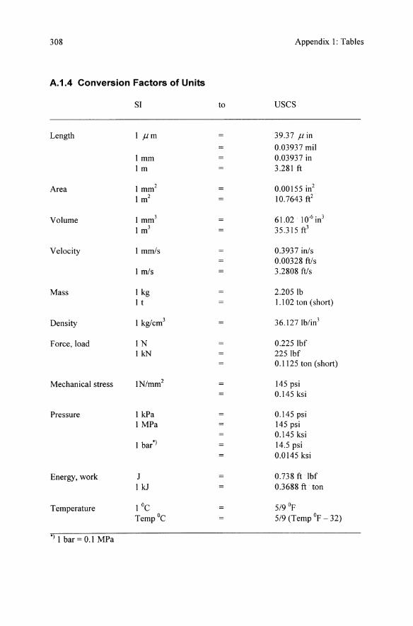
A.1.4 Conversion Factors of Units
SI to uses
Length If-Lm 39.37 f-L in
0.03937 mil I mm 0.03937 in 1m 3.281 ft
Area I mm2 0.00155 in2 1m2 10.7643 ft2
Volume I mm3 61.02 10.6 in3
1m3 35.315 ft3
Velocity I mmls 0.3937 inls 0.00328 ft/s
I mls 3.2808 fils
Mass I kg 2.2051b I t 1.102 ton (short)
Density I kg/cm3 36.1271b/in3
Force, load IN 0.2251bf I kN 225 Ibf
0.1125 ton (short)
Mechanical stress IN/mm2 145 psi 0.145 ksi
Pressure I kPa 0.145 psi I MPa 145 psi
0.145ksi I bar') 14.5 psi
0.0145 ksi
Energy, work J 0.738 ft Ibf I kJ 0.3688 ft ton
Temperature IOe 5/9 of
Temp °e 5/9 (Temp of - 32)
') I bar = 0.1 MPa
Appendix 2: Flow Curves of Common Materials
by K. Pohlandt
A.2.1 Experimentally Determined Flow Curves
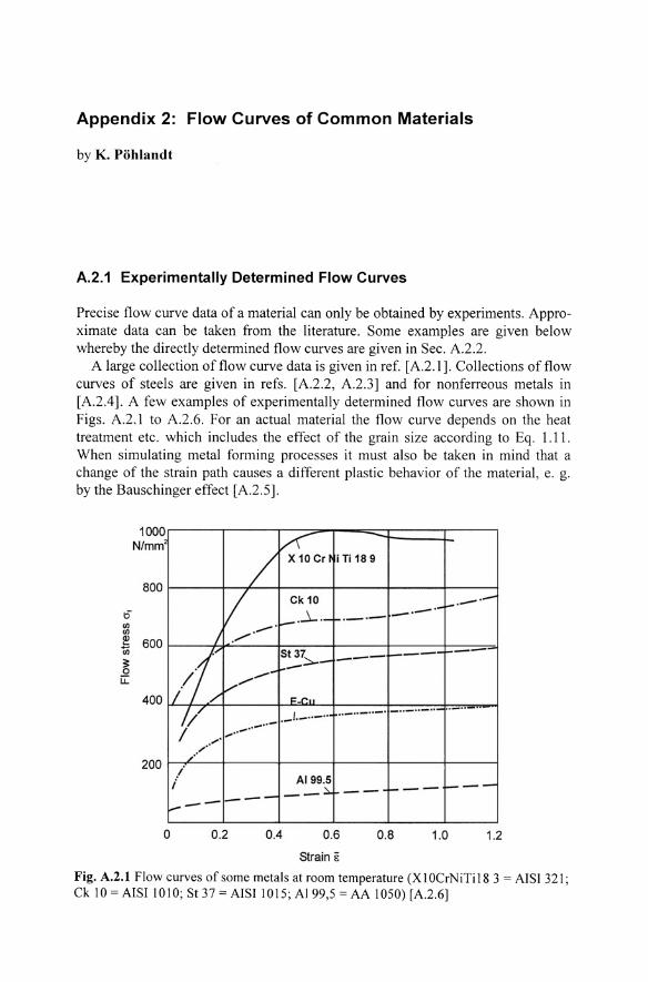
Precise flow curve data of a material can only be obtained by experiments. Approximate data can be taken from the literature. Some examples are given below whereby the directly determined flow curves are given in Sec. A.2.2.
A large collection of flow curve data is given in ref. [A.2.1]. Collections of flow curves of steels are given in refs. [A.2.2, A.2.3] and for nonferreous metals in [A.2A]. A few examples of experimentally determined flow curves are shown in Figs. A.2.1 to A.2.6. For an actual material the flow curve depends on the heat treatment etc. which includes the effect of the grain size according to Eq. 1.11 . When simulating metal forming processes it must also be taken in mind that a change of the strain path causes a different plastic behavior of the material, e. g. by the Bauschinger effect [A.2.5].
1000 N/mm ~
800
1:5" III III
~ 600 (ji
?; 0 u::
400
/ X10Cd i Ti 18 9
V _. Ck10 -'--.-.~ -' -'~ '- -_o-j ./.
/l St 37;::.. --- !----- .... ---- - .-
,/-
1".1": ..
200
/;/ .. _ .. _ .. _0 - " .. .. - __ 40
" •• 06*" - " -
._J._ .. - .. j
;' / '
/ '
i i AI 99.5 -----:::... -- 1---.------
o 0.2 0.4 0.6 0.8 1.0 1.2
Strain E
Fig. A.2.1 Flow curves of some metals at room temperature (X 1 OCrNiTil8 3 = AISI 321; Ck 10 = AISI 1010; St37=AISI 1015;AI99,5=AA 1050)[A.2.6]
310 Appendix 2: Flow Curves of Common Metals
43.5
36.25 'iii .:x!
I:i !lJ !lJ
~ 29.0 !lJ
;: 0 u:
21.75
14.5
NE .§ z I:i (/) !lJ
2:? iii ;: 0 u:
300
250
200
150
100 o
/
E",jOS" '1---
V VI 1/ 3605"
_x Lx- i--It_ _w
lIX 4015"
/' ~
0.4 0.8 1.2
Equivalent strain E
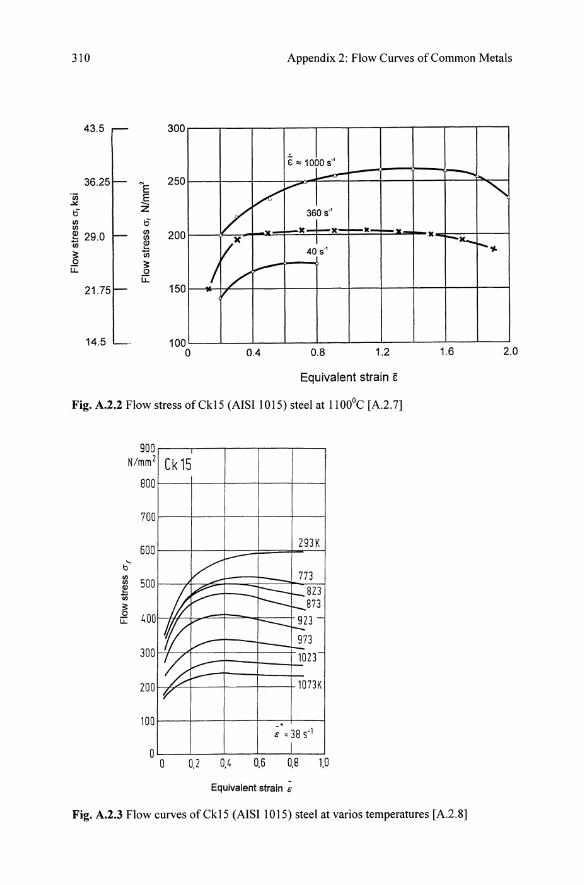
Fig. A.2.2 Flow stress ofCkl5 (AISI 1015) steel at 1 100°C [A.2.7]
900 N/mm 2 Ck15
800
700
600 293 K
b" !lJ
500 '" ~ ~ 400 G:
300
200
V I---
1773
jp ~ F==: t- 823 1-873
l/(( -- 923-t-
973 V r--"-
~ 1023-,...-- 1073K p-
100
I ;'=385-1
I I a o 0,2 0.4 0.6 0,8 1.0
Equivalent strain;
....
II r-X-
1.6
Fig. A.2.3 Flow curves of Ck15 (AISI 1015) steel at varios temperatures [A.2.8]
""-
r--y.
2.0
A.2.l Experimentally Determined Flow Curves
900 N/mm 2
800
700
600
500
'"' b
~ 400 ~ en
~ 300
200
100
o o
20MnCr5
I 293 K ~I
I 773 -
I ~ r- 823 -It V -r-- 873
r-- --r---~23
f( - I--~73 -:.
:--------
1023
/' - -lO73K
I
~ =38s-1
I 0.2 0,4 0,5 0,8 1,0
-Equivalent strain 8
311
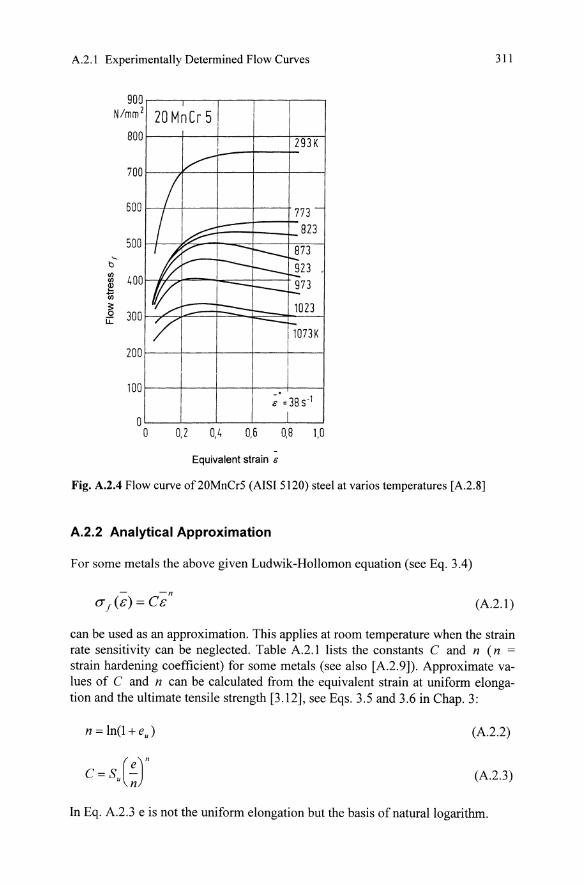
Fig. A.2.4 Flow curve of20MnCr5 (ArSr 5120) steel at varios temperatures [A.2.S]
A.2.2 Analytical Approximation
For some metals the above given Ludwik-Hollomon equation (see Eq. 3.4)
(A2.1 )
can be used as an approximation. This applies at room temperature when the strain rate sensitivity can be neglected. Table A2.l lists the constants C and n (n = strain hardening coefficient) for some metals (see also [A.2.9]). Approximate values of C and n can be calculated from the equivalent strain at uniform elongation and the ultimate tensile strength [3.12], see Eqs. 3.5 and 3.6 in Chap. 3:
n = In(l +eJ (A2.2)
(A2.3)
In Eq. A2.3 e is not the uniform elongation but the basis of natural logarithm.
312 Appendix 2: Flow Curves of Common Metals
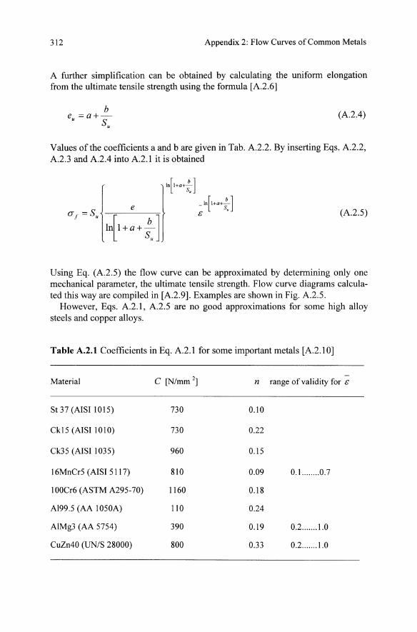
A further simplification can be obtained by calculating the uniform elongation from the ultimate tensile strength using the formula [A.2.6]
b e =a+-• S.
(A. 2.4)
Values of the coefficients a and b are given in Tab. A.2.2. By inserting Eqs. A.2.2, A.2.3 and A.2.4 into A.2.1 it is obtained
(A.2.5)
Using Eq. (A.2.5) the flow curve can be approximated by determining only one mechanical parameter, the ultimate tensile strength. Flow curve diagrams calculated this way are compiled in [A.2.9]. Examples are shown in Fig. A.2.5.
However, Eqs. A.2.1, A.2.5 are nO good approximations for some high alloy steels and copper alloys.
Table A.2.t Coefficients in Eq. A.2.1 for some important metals [A.2.1 0]
-Material C [N/mm 2] n range of validity for &
St 37 (AISI 1015) 730 0.10
Ckl5 (AISI 1010) 730 0.22
Ck35 (AISI 1035) 960 0.15
16MnCr5 (AISI 5117) 810 0.09 0.1... ..... 0.7
100Cr6 (ASTM A295-70) 1160 0.18
A199.5 (AA 1050A) 110 0.24
AIMg3 (AA 5754) 390 0.19 0.2 ....... 1.0
CuZn40 (UN/S 28000) 800 0.33 0.2 ....... 1.0
A.2.1 Experimentally Determined Flow Curves
Table A.2.2 Coefficients a and b in Eq. A.2A [A.2.6]
Mild steels, deep-drawing steels
General-purpose structural steels
Carbon steels, low-alloyed steels, speroidized annealed
~E E .....
Z .....
b
1600
1400 I-
1200
1000 I-
800 I-
600 I-
400 I-
200
o 0.10
I
0.20 0.30
I
0.40 0.50
c
a 10.2
12
-1.27
3.16
313
2730
7740
5860
I Su 200 N/mm'
1100 1!XXl
9ll
8tX! - 1-1-700
600 -+-+-500
400
0.60 0.70 0.80
Fig. A.2.S Flow curves of carbon and alloy steels, speroidized-annealed according to Eq . A.2 .S [A.2 .9]
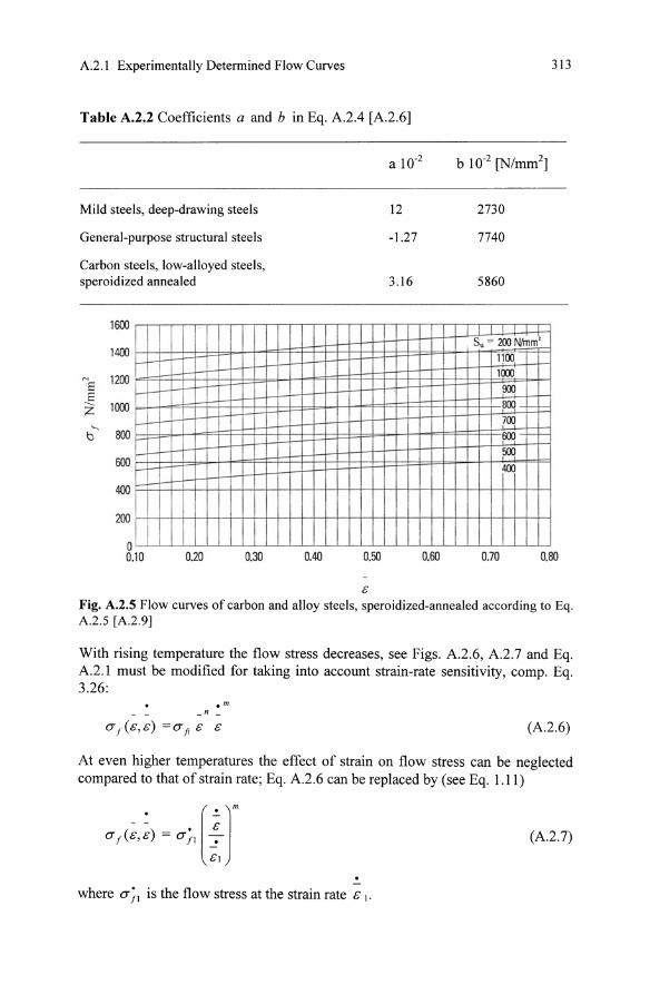
With rising temperature the flow stress decreases, see Figs. A.2.6, A.2.7 and Eq. A.2.1 must be modified for taking into account strain-rate sensitivity, compo Eq. 3.26:
.m n
(A.2.6)
At even higher temperatures the effect of strain on flow stress can be neglected compared to that of strain rate; Eq. A.2.6 can be replaced by (see Eq. 1.11)
(A.2.7)
where a;\ is the flow stress at the strain rate c \.
314 Appendix 2: Flow Curves of Common Metals
1.0 .-------,-----,----,--....,
--f> 0.8 1---4----+---1---1 o N
'1 (f) 0.6 1---- -+---No..---II------1 -... E
,g 0.4 I--- ----if--- ---+---l-""'-.J----j (f)
0.2 '--_---1-_----1. __ .!--_----'
Materials 20 MnCr 5 (AISI 5120) 15 CrNi 6 (AISI 4320) 42 CrMa 4 (AISI 4140 H) 100 Cr 6 (AISI L3)
973 1073 1173 1273 1373
Temperature, °c Fig. A.2.6 Dependence of flow stress of some steels on temperature [A.2.8]
200
N/mm'
100 80 60
" 40 th th
~ 20 th
~ c;:: 10
8 6
4
2
r-- 20'C
~ '//
~ r
~
o 1.5
- 100'C - 150'C
--200'C
---250'C --- I --:::300'C
r---- i-.
V 4OO'C
Temperature 500' C
3.0 4.5 6.0 7.5 9.0
equivalent strain i
Fig. A.2.7 Flow stress of aluminum as a function of strain at varios temperatures (Courtesy ASM International) [A.2.I]
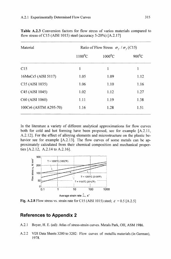
For steels typical values of the strain-rate sensitivity index m are from -0.02 to + 0.05 at 20 - 450°C and from +0.1 to + 0.2 above 850°C. Of course, this applies only as an approximation. Eq. A.2.7 is demonstrated by Fig. A.2.8. The curves shown in this figure can be used for a variety of metals by applying the values listed in Tab. A.2.3 . For values of m above 0.3 the term superplasticity is convenient.
A.2.1 Experimentally Determined Flow Curves 315
Table A.2.3 Conversion factors for flow stress of varios materials compared to flow stress ofC15 (AISI 1015) steel (accuracy 5-20%) [A.2.l7]
Material Ratio of Flow Stress (if / (if (C15)
1l00OC 10000C 900°C
C15
16MnCr5 (AISI 5117) 1.05 1.09 1.12
C35 (AISI 1035) 1.06 1.10 1.16
C45 (AISI 1045) 1.02 1.12 1.27
C60 (AISI 1060) 1.11 1.19 1.38
100Cr6 (ASTM A295-70) 1.16 1.28 1.51
In the literature a variety of different analytical approximations for flow curves both for cold and hot forming have been proposed, see for example [A.2.11, A.2.l2]. For the effect of alloying elements and microstructure on the plastic behavior see for example [A.2.13]. The flow curves of some metals can be approximately calculated from their chemical composition and mechanical properties [A.2.l2, A.2.14 to A.2.16].
500' NE E Z 200 t5
I " '" ~ 100
~ LL 50
01
• I .
\J T=1200:C(213~ '--"....,=-----i---- T = 11 oo'C (2012'F) I
I I ---l
0.1 10 100 1000
Average strain rate ~., 5-'
Fig. A.2.S Flow stress vs. strain rate for CIS (AISI lOIS) steel; & = 0.5 [A.2.5]
References to Appendix 2
A.2.1 Boyer, H. E. (ed): Atlas of stress-strain curves. Metals Park, OH, ASM 1986.
A.2.2 VDI Data Sheets 3200 to 3202: Flow curves of metallic materials (in German), 1978.
316 Appendix 2: Flow Curves of Common Metals
A2.3 Dahl, W.; Rees, H.: The stress-strain curve of steel (in German). DUsseldorf, Verlag Stahleisen 1976.
A2.4 Deutsche Gesellschaft fUr Metallkunde (DGM): Atlas of hot formability of nonFerrous metals. Vol. 1: Aluminium and its alloys. Vol. II: Copper and Its Alloys. Oberursel, DGM 1978.
A2.5 Szabadits, 0.; Krallics, G.; Lovas-J.: Evaluation of cyclic flow curves for the calculation of sheet metal forming processes (in German), Blech, Rohre, Profile 41 (1994) 190-194.
A2.6 Dahl, W.; Hesse, W.; Krabiell, A.: Strain-hardening of steel and its influence on the parameters of the tensile test (in German), Stahl und Eisen 103 (\ 983), 87-90.
A.2.7 BUhler, H.; Vollmer, 1.: Flow curves of metallic materials at large strains and strain rates (in German), Ind.-Anz. 91 (\969),2021-2023.
A.2.8 Diether, U.: Determining flow curves at elevated temperatures in the upsetting test (in German), Ind.-Anz. 102 (1979), 67-68.
A.2.9 Lange, K. (ed): Cold Forming and Fine Blanking. Bern, Hallwag 2000.
A2.10 Hensel, A; Spittel, Th.: Force and work requirements of metal forming processes (in German). Leipzig, Grundstoffindustrie 1976.
A2.11 Lehmann, G.; Lemke, J.: Development of a new composite flow curve statement, steel research 69 (1998), 237-239.
A.2.12 Schotten, K.; Blech, W.; Dahl, W.: Modelling of flow curves for hot deformation, steel research 69 (1998), 193-197.
A.2.13 MUschenborn, W.; Grzesik, D.; KUppers, W.: Cold formability of flat rolled products. In: Verein Deutscher EisenhUttenleute (ed): Steel. A handbook for materials research and engineering. Vol. 1: Fundamentals. Berlin, Springer-Verlag 1992.
A2.14 Leykamm, H.: Calculation of flow curves and of strength, elongation to fracture and fracture necking of cold formed parts of extrusion steels from chemical analysis afterWagenbach (in German), Draht 29 (1978), 648-651.
A2.15 Spittel, Th.; Spittel, M.: Calculation ofthe influence of chemical composition on the flow stress of steel in hot forming (in German), Neue HUtte 36 (\991), 329-334.
A2.16 Takuda, H.; Kikuchi, S.; Hatta, N.: Modelling of comprehensive formula for flow curves of aluminium alloys at elevated temperatures, Materials Transactions JIM 34 (1993), 711-717.
A2.17 Neuberger, F.; et al.: Testing common forging metals by upsetting tests (in German), Maschinenbau-Technik 7 (1958), 249-254.
Appendix 3: Theoretical Models of the FLO's
by D. Banabic
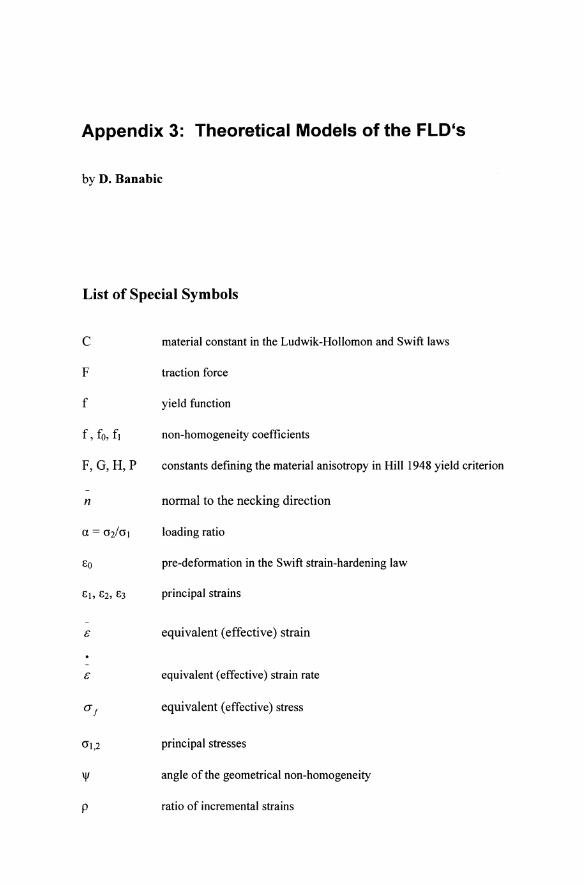
List of Special Symbols
C
F
f
f, fo, f1
F,G,H,P
n
EO
'II
P
material constant in the Ludwik-Hollomon and Swift laws
traction force
yield function
non-homogeneity coefficients
constants defining the material anisotropy in Hill 1948 yield criterion
normal to the necking direction
loading ratio
pre-deformation in the Swift strain-hardening law
principal strains
equivalent (effective) strain
equivalent (effective) strain rate
equivalent (effective) stress
principal stresses
angle of the geometrical non-homogeneity
ratio of incremental strains
318 Appendix 3: Theoretical Models of the FLD's
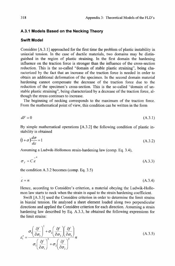
A.3.1 Models Based on the Necking Theory
Swift Model
Considere [A3.1] approached for the first time the problem of plastic instability in uniaxial tension. In the case of ductile materials, two domains may be distinguished in the region of plastic straining. In the first domain the hardening influence on the traction force is stronger than the influence of the cross-section reduction. This is the so-called "domain of stable plastic straining", being characterized by the fact that an increase of the traction force is needed in order to obtain an additional deformation of the specimen. In the second domain material hardening cannot compensate the decrease of the traction force due to the reduction of the specimen's cross-section. This is the so-called "domain of unstable plastic straining", being characterized by a decrease of the traction force, although the stress continues to increase.
The beginning of necking corresponds to the maximum of the traction force. From the mathematical point of view, this condition can be written in the form
dF=O (A3.l)
By simple mathematical operations [A3.2] the following condition of plastic instability is obtained
{I + CT)dCT =1 ds
Assuming a Ludwik-Hollomon strain-hardening law (comp. Eq. 3.4),
n
the condition A3.2 becomes (comp. Eq. 3.5)
s=n
(A3.2)
(A3.3)
(A3.4)
Hence, according to Considere's criterion, a material obeying the Ludwik-Hollomon law starts to neck when the strain is equal to the strain hardening coefficient.
Swift [A3.3] used the Considere criterion in order to determine the limit strains in biaxial tension. He analysed a sheet element loaded along two perpendicular directions and applied the Considere criterion for each direction. Assuming a strain hardening law described by Eq. A3.3, he obtained the following expressions for the limit strains:
(A3.5)
A.3.1 Models Based on the Necking Theory 319
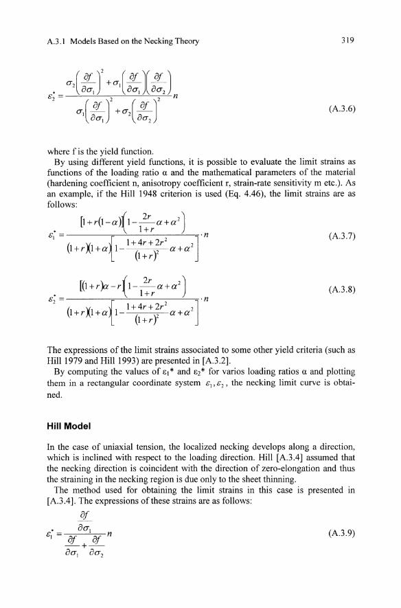
(A.3.6)
where f is the yield function. By using different yield functions, it is possible to evaluate the limit strains as
functions of the loading ratio (l and the mathematical parameters of the material (hardening coefficient n, anisotropy coefficient r, strain-rate sensitivity m etc.). As an example, if the Hill 1948 criterion is used (Eq. 4.46), the limit strains are as follows:
[1+r(l-all-~a+a2) • \ l+r
&1 = ( X {1+4r+2r2 2]·n (A.3.7) l+r l+at1- (l+rY a+a
[(1 +r)a -r {1-~a+a2) • \ l+r
&2 = ·n ( X {1+4r+2r2 2] l+r l+at1- (l+ry a+a
(A.3.8)
The expressions of the limit strains associated to some other yield criteria (such as Hill 1979 and Hill 1993) are presented in [A.3 .2].
By computing the values of I:J* and 1:2* for varios loading ratios (l and plotting them in a rectangular coordinate system &1' &2' the necking limit curve is obtained.
Hill Model
In the case of uniaxial tension, the localized necking develops along a direction, which is inclined with respect to the loading direction. Hill [A.3.4] assumed that the necking direction is coincident with the direction of zero-elongation and thus the straining in the necking region is due only to the sheet thinning.
The method used for obtaining the limit strains in this case is presented in [A.3.4]. The expressions of these strains are as follows:
81
(A.3.9)
320 Appendix 3: Theoretical Models of the FLD's
Of • ocr2
&2 = af Of n - +-acrl acr2
It can be seen that
&; +&; = n
(A.3 .10)
(A.3 .11)
This is the equation of a line parallel with the second bisectrix of the rectangular coordinate system &1 ' &2 and intersecting the vertical axis at the point (0, n).
According to Eq. A.3 .11 the FLD computed on the basis of Hill's model does not depend on the yield criterion, but only on the value of the hardening coefficient.
A.l.2 Models Based on the Theory of Sheet Non-Homogeneity
On the basis of the experimental investigations concerning the strain localization of some specimens subjected to hydraulic bulging or punch stretching, Marciniak [A.3 .5] concluded that the necking is usually initiated by a geometrical or structural non-homogeneity of the material. This non-homogeneity may be associated to a variation of the sheet thickness (geometrical non-homogeneity) or some defects of the lattice (structural non-homogeneity).
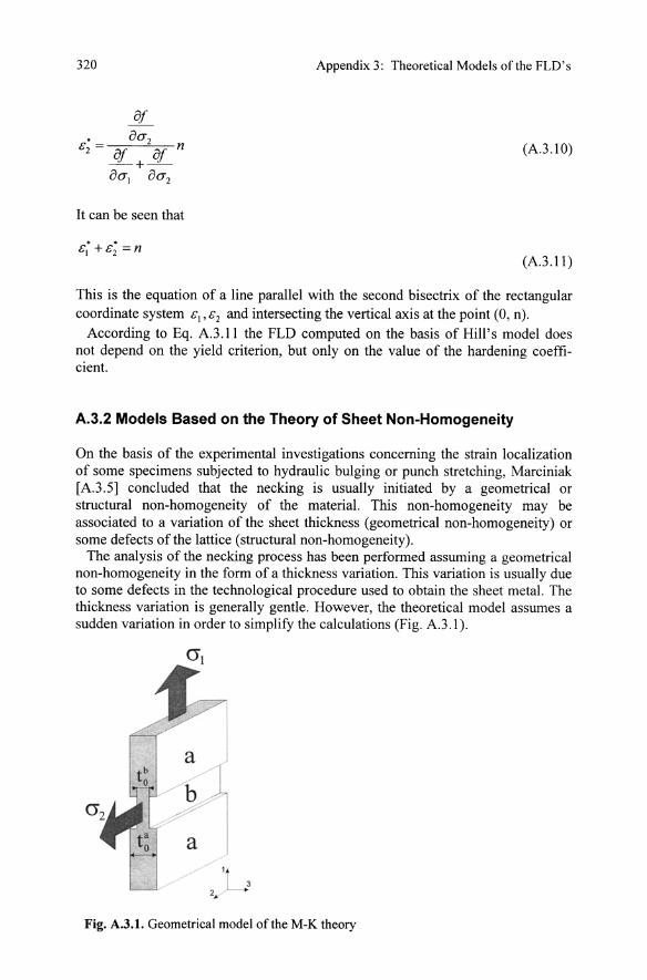
The analysis of the necking process has been performed assuming a geometrical non-homogeneity in the form of a thickness variation. This variation is usually due to some defects in the technological procedure used to obtain the sheet metal. The thickness variation is generally gentle. However, the theoretical model assumes a sudden variation in order to simplify the calculations (Fig. A.3.1).
Fig. A.3.t. Geometrical model of the M-K theory
A.3.2 Models Based on the Theory of Sheet Non-Homogeneity 321
The theoretical model proposed by Marciniak (Fig. A.3.l) assumes that the specimen has two regions: region "a" having a uniform thickness toa, and region "b" having the thickness tob. The initial geometrical non-homogeneity of the specimen is described by the so-called "coefficient of geometrical non-homogeneity", f, expressed as the ratio of the thickness in the two regions:
(A.3.l2)
The strain and stress states in the two regions are analyzed with respect to the principal strain Clb in region b and the principal strain &t in region a. When the
ratio &\b / &t becomes too high (infinite in theory, above 10 in practice), one may consider that the deformation of the specimen is localized in region "b", see Fig. A.3.2.
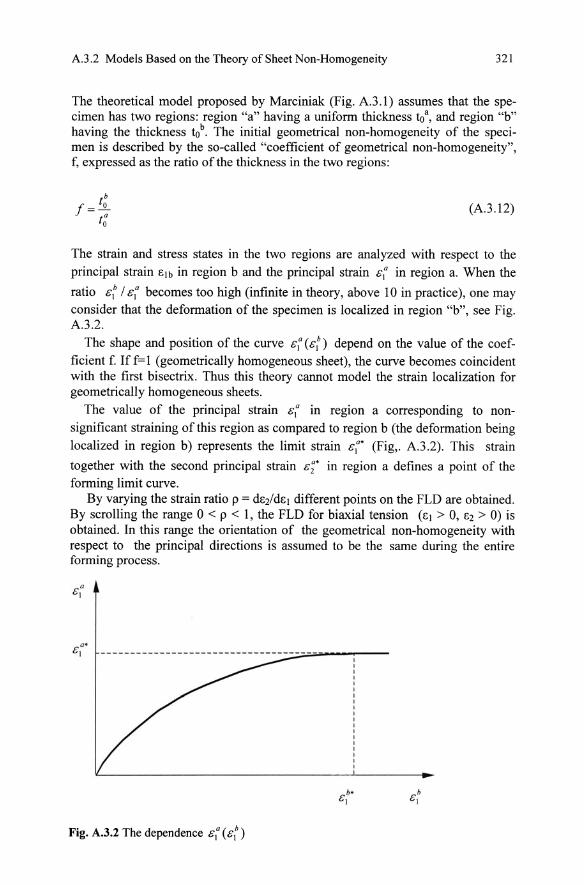
The shape and position of the curve &t (&\b) depend on the value of the coefficient f. Iff=1 (geometrically homogeneous sheet), the curve becomes coincident with the first bisectrix. Thus this theory cannot model the strain localization for geometrically homogeneous sheets.
The value of the principal strain &t in region a corresponding to nonsignificant straining of this region as compared to region b (the deformation being localized in region b) represents the limit strain &t' (Fig,. A.3.2). This strain
together with the second principal strain &;' in region a defines a point of the forming limit curve.
By varying the strain ratio p = dC2/dcl different points on the FLD are obtained. By scrolling the range 0 < p < 1, the FLD for biaxial tension (cl > 0, C2 > 0) is obtained. In this range the orientation of the geometrical non-homogeneity with respect to the principal directions is assumed to be the same during the entire forming process.
Fig. A.3.2 The dependence &\0 (&t )
322 Appendix 3: Theoretical Models of the FLD's
The Marciniak model was further developed by Marciniak and Kuczinski [A.3.6] and Marciniak, Kuczinski and Pokora [A3.7] , usually being briefly denominated by M-K model.
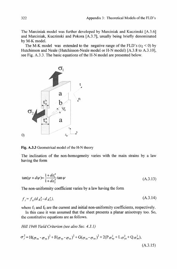
The M-K model was extended to the negative range of the FLD' s (e2 < 0) by Hutchinson and Neale (Hutchinson-Neale model or H-N model) [A3.8 to A3 .IO], see Fig. A.3.3. The basic equations of the H-N model are presented below.
0)
a b /
f % ~
a
t
n •
Fig. A.3.3 Geometrical model of the H-N theory
The inclination of the non-homogeneity varies with the main strains by a law having the form
l+dcO
tan( \If + d \If)== __ I tan \If l+dc; (A3 .I3)
The non-uniformity coefficient varies by a law having the form
(A.3.14)
where fJ and fo are the current and initial non-uniformity coefficients, respectively. In this case it was assumed that the sheet presents a planar anisotropy too. So,
the constitutive equations are as follows.
Hill 1948 Yield Criterion (see also Sec. 4.3.1)
(A.3.IS)
Appendix 3: Theoretical Models of the FLD's 323
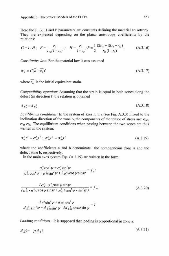
Here the F, G, H and P parameters are constants defining the material anisotropy. They are expressed depending on the planar anisotropy coefficients by the relations:
G=l-H; F= ro r90(1 + ro)
H=~;P= 1 (2r45 +1)(ro +r90 ).
l+ro 2 r90 (1+rO)
(A.3.l6)
Constitutive law: For the material law it was assumed
(A.3.l7)
where Go is the initial equivalent strain.
Compatibility equation: Assuming that the strain is equal in both zones along the defect (in direction t) the relation is obtained
(A.3.l8)
Equilibrium conditions: In the system of axes n, t, z (see Fig. A.3.3) linked to the inclination direction of the zone b, the components of the tensor of stress are: crnD>
crtb crnt. The equilibrium conditions when passing between the two zones are thus written in the system:
(A.3.19)
where the coefficients a and b denominate the homogeneous zone a and the defect zone b, respectively.
In the main axes system Eqs. (A.3.l9) are written in the form:
( a~ - ar )COSIt' sin It' = f . ( a~2 -aU cos It' sin It' + a~ 2 ( cos2 It' - sin 2 It' ) 1 '
(A.3.20)
1.
Loading conditions: It is supposed that loading is proportional in zone a:
d G~= pd Gr. (A.3.21)
324 Appendix 3: Theoretical Models ofthe FLD's
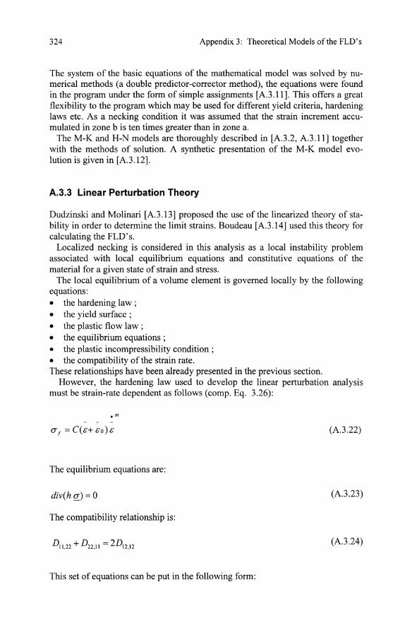
The system of the basic equations of the mathematical model was solved by numerical methods (a double predictor-corrector method), the equations were found in the program under the form of simple assignments [A3.11]. This offers a great flexibility to the program which may be used for different yield criteria, hardening laws etc. As a necking condition it was assumed that the strain increment accumulated in zone b is ten times greater than in zone a.
The M-K and H-N models are thoroughly described in [A3.2, A3.11] together with the methods of solution. A synthetic presentation of the M-K model evolution is given in [A3.12].
A.3.3 Linear Perturbation Theory
Dudzinski and Molinari [A3.l3] proposed the use of the linearized theory ofstability in order to determine the limit strains. Boudeau [A3.14] used this theory for calculating the FLD's.
Localized necking is considered in this analysis as a local instability problem associated with local equilibrium equations and constitutive equations of the material for a given state of strain and stress.
The local equilibrium of a volume element is governed locally by the following equations: • the hardening law ; • the yield surface; • the plastic flow law; • the equilibrium equations; • the plastic incompressibility condition ; • the compatibility of the strain rate. These relationships have been already presented in the previous section.
However, the hardening law used to develop the linear perturbation analysis must be strain-rate dependent as follows (comp. Eq. 3.26):
(A3.22)
The equilibrium equations are:
div(h Q:) = 0 (A3.23)
The compatibility relationship is:
Dl1,22 + D22•11 = 2D12,12 (A3.24)
This set of equations can be put in the following form:
Appendix 3: Theoretical Models of the FLO's 325
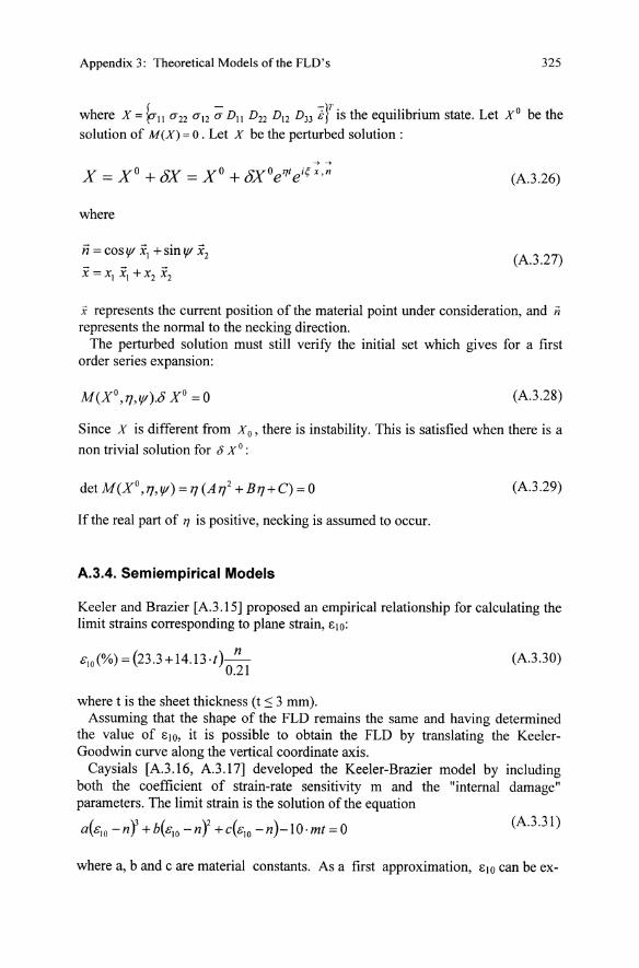
where X = ~11 U22 uI2 ~ DII D22 DI2 D33 iJ is the equilibrium state. Let X O be the solution of M(X) = o. Let X be the perturbed solution:
-> ->
X = XO + 8X = XO + t5XOe"/eiqx ,n
where
ii = cos If XI + sin If x2
X = XI XI + x2 x2
(A.3.26)
(A.3.27)
X represents the current position of the material point under consideration, and ii represents the normal to the necking direction.
The perturbed solution must still verify the initial set which gives for a first order series expansion:
(A.3.28)
Since X is different from x o, there is instability. This is satisfied when there is a
non trivial solution for 0 X o:
(A.3.29)
If the real part of 1] is positive, necking is assumed to occur.
A.3.4. Semiempirical Models
Keeler and Brazier [A. 3 .15] proposed an empirical relationship for calculating the limit strains corresponding to plane strain, 1::10:
C\O(%) = (23.3+14.13.t )_n_ 0.21
where t is the sheet thickness (t :s 3 mm).
(A.3.30)
Assuming that the shape of the FLD remains the same and having determined the value of 1::10, it is possible to obtain the FLD by translating the KeelerGoodwin curve along the vertical coordinate axis.
Caysials [A. 3 .16, A.3.17] developed the Keeler-Brazier model by including both the coefficient of strain-rate sensitivity m and the "internal damage" parameters. The limit strain is the solution of the equation
a(clo -nY +b(clo -n'f +c(c\O -n)-lO.mt = 0 (A.3.31)
where a, b and c are material constants. As a first approximation, 1::10 can be ex-
326 Appendix 3: Theoretical Models of the FLD's
pressed as follows:
810 =n+5mt (A.3.32)
The results obtained on the basis of this model are in very good agreement with experiments.
References to Appendix 3
A3.1 Considere, A: Use of the iron and steel in buildings (in French), Ann. des Ponts et Chaussees 9 (1885), 574-575.
A3.2 Banabic, D.; Dorr, I. R.: Modelling and simulation of sheet metal forming processes (in Romanian), Transilvania Press, Cluj-Napoca 1995.
A3.3 Swift, H. W.: Plastic instability under plane stress, J. Mech. Phys. Solids 1 (1952),1-16.
A3.4 Hill, R.: On discontinous plastic states, with special reference to localized necking in thin sheets, J. Mech. Phys. Solids 1 (1952), 19-30.
A.3.5 Marciniak, Z.: Stability of plastic shells under tension with kinematic boundary condition, Archiwum Mechaniki Stosorwanej, 17 (1965),577-592.
A3.6 Marciniak, Z.; Kuczynski, K.: Limit strains in the processes of stretch forming sheet metal, Int. J. Mech. Sci. 9 (1967), 609-620.
A3.7 Marciniak, Z.; Kuczynski, K.; Pokora, T.: Influence of the plastic properties ofa material on the FLD for sheet metal in tension, Int. J. Mech. Sci. 15 (1973), 789-805.
A.3.8 Hutchinson, R. W.; Neale, K. W.: Sheet necking. In: Koistinen, D. P.; Wang, N. M. (eds): Mechanics of sheet metal forming, New Y orkILondon, Plenum Press 1978, 11-126.
A3.9 Hutchinson, R. W.; Neale, K. W.: Sheet necking II. Time independent behavior. In: Koistinen, D. P.; Wang, N. M. (eds): Mechanics of sheet metal forming, New YorkILondon, Plenum Press 1978, 127-153.
A3.10 Hutchinson, R. W.; Neale, K. W.: Sheet necking III. Strain-rate effects. In: Koistinen, D. P.; Wang, N. M. (eds): Mechanics of sheet metal forming, New YorkILondon, Plenum Press 1978,269-285.
A.3.11 Banabic, D.: Research on thin sheet metal formability (in Romanian). PhD Thesis, Technical University ofCluj-Napoca 1993.
A3.12 Banabic, D.; Dorr, I. R.: Formability of thin sheet metals (in Romanian). O. I. D. I. C. M .. Bucharest 1992.
Appendix 3: Theoretical Models of the FLD's 327
A3.13 Dudzinski, D.; Molinari A: Instability of visco-plastic deformation in biaxial loading, Compt. Rend. Acad. Sci. Paris, 307 (1988),1315-1321.
A3.l4 Boudeau, N.: Prediction of instability in local elasto-plastic instabilities (in French). PhD Thesis, University of Franche-Compte 1995.
A3.15 Keller, S. P.; Brazier, W. G.: Relationship between laboratory material characterization and press-shop formability, Micro Alloying (1975), 21-32.
A3.16 Cayssials, F.: A new method for predicting FLC. In: Proc. IDDRG Congr., Brussels June 1998.
A3.17 Cayssials, F.: The version of the "Cayssials" FLC model. IDDRG Meeting Working Group III, Birmingham 1999, 1-7.
Index
adiabatic heating 75, 231 alminum282 aluminum alloy 219, 230, 243 - springback 230 aluminum-magnesium alloy 14 aluminum sheet 46, 48, 230 amorphous structures 56 anisotropy (plastic) 23 - axisymmetric material 86, 91 - coefficient (see also r-value) 122, 131,134,188 - normal 35, 84 - orthogonal (see orthotropy) - planar 36, 123 annealing 18, 20, 233 arc-length factor 269 axisymmetry (see cylindric orthotropy)
Bauschinger effect 53, 280, 309 bending - closed die 230 bending of tubes 95 bending test 186 blue brittleness Brinell hardness 219 bulge test, hydraulic 84, 182, 193,200 Burgers vector 6
can-making 230 central difference method 283 Considere criterion 318 continuity equation 46 convergence criterion 265 - absolute maximum residual force 267 - absolut maximum velocity 267 - energy norm 267 - number of iterations 267 - relative residual force norm 266 - relative velocity norm 266
consistent linearization 298 copper 44 copper alloys (see CuZn alloys) corrosion (see also stress-corrosion) 232 Cosserat continuum 28, 42, 45 crack 8 - formation (initiation) 102, 106 crystal (see metal, monocrystal, polycrystal) - anisotropy 33 - lattice ( see lattice) crystal orientation 28 - mapping32 cup drawing test 184 CuZn alloys (see also brass) 16, 231 cyclic deformation curves 240 cylinder upsetting test (see also upsetting test) 67 - lubrication 68 - diameter measurement 70 - equivalent strain 67 - errors 68 - forming limit 104 - friction 68 - specimen (see Rastegaev specimen) cylindric orthotropy 86
damping - factor 269, 282 - matrix 284 deep-drawability 35,85 deep-drawing 86, 174, 230 deep-drawing sheet 86 deep-drawn cups 230 deformation - cold 10 - gradient tensor 254 - heat (see adiabatic heating) - hot 56 - isochoric 259
330
- nonlinear kinematics of253 - path (see also strain path) 47,54 - softening 53 - work 47,54 direction distribution function (see also pole figure) 30 dislocation 6 - annihilation 11 - density 10, 12, 15, 17 - edge 6 - gliding (see also slipping) 8 - screw 6 ductile-to brittle transition 15, 103 ductility 63, 102 dynamic relaxation 287
earing 36 elasto-plastic - dynamic explicit method 282 - static implicit method 276 element types 291 elongation - elastic 3 - plastic 3 - to fracture 66, 103 equilibrium conditions 323 equivalent (effective) strain (see also Umformgrad) 4, 67, 79,97,260 - at fracture 101, 103 - rate 259 Erichsen test (see formability tests) Euler angles 29 Euler space 44 Euler time integration 271 extrusion 230, 240 - cold 241 - die 223 - ejection 229 - forward (see forward extrusion) - free 94 - hydrostatic 225 - warm 241, 245
failure 102 failure limit curves 106 fatigue strength 240, 243 finite difference method 288 finite strain - increment 279 - tensor 255 - Green Lagrangian 255
Index
FLD (see forming limit diagram) flow curve (see also Ludwik-Hollomon equation) 4,20,63,84, 101,237,260,273 - data 309 - effect of alloying elements 284 - elevated temperatures 75 - error 97 - hot 20 - isothermal 75 flow surface 92 flow stress (see also yield stress) 4, 12,260 forgeability 106 formability 12,63,67, 102 - sheet metal 173, 176,207 formability indices 175 formability tests - Eisenkolb 185 - Engelhardt 185 - Erichsen 181 - Fukui 185 - Gtith 182 - Guyot 182 - Hecker 181 - Olsen 182 - Petrasch 184 - Sachs 182, 184
- Swift 182, 184 forming
- bulk metal 63 - cold 17 - hot 16,20,75,82 - multi-stage 221 - sheet metal (see also bending, deep-drawing, stretch-forming) 229 forming limit (see also formability) 63, 173 - in bulk metal forming 101 forming limit diagram - Hill model 319 - Hutchinson-Neal model 322 - intrinsic 199 - Keeler 189, 193 - Keeler and Goodwin 189 - linear perturbation theory 324 - Marcinial-Kuczinsky model 322 - semiempirical model 325 - Swift model 318 forward extrusion (see also hollow forward extrusion) 94, 218, 222 fracture 102, 191,205 Frank-Read source 10 friction coefficient 74, 225
Index
Galerkin weighted residual method 275 glide system (see also slip system) 15,36, 50 glide system tensor 41 grain 4,10 - formation 19 - growth 19
limiting dome height 187 limiting drawing ratio (see deep-drawability) limit stress diagram 191 line search 269 lower yield point (see sharp yield point) lubricant 242
331
- size 4, 19 grain boundaries 7, II - large angle 17
Ludwik (Hollomen) equation 66, 311, 318 Liiders lines (Liiders strips) 14
- small angle (see also subgrain boundaries) 8, 18 grid (see also visioplasticity) 103,218
Markov's variational principle 260 martensitic (phase) transformation 56 mass matrix 293 - lumped 284
Hall-Petch equation 15 mass-spring-damper system 292 hardening (see also strain hardening) 53 material hardening coefficient (see also n-value, - compressible (see powder metals) strain hardening coefficient) 188 - cubic 55 hardness (see also Vickers hardness) 50, - polycrystalline (see also polycrystals) 26 219,243 - flow studies (see visioplasticity method) - relation with flow stress 220 mean (normal) stress 63, 67 Hasek test 196 mechanical properties (see also ductility, strength) 64 heading 237 mechanical twinning 13,20,56 heat meshing 292 - capacity matrix 275 - hexahedral elements 292 - conduction matrix 275 - tetrahedral elements 292 - transfer equation 275 mesoscopic plasticity 36 heat flux 275 metal 9 heat treatment (see also annealing) 16, 233 - body cubic centered (bcc) 10, 14, 51 Hill 92, 130, 136, 145, 147 - face cubic centered (fcc) 10, 13,43,51 hollow forward extrusion 94, 229 - hexagonal 15,56 Hopkinson bar 75 metal forming process (see forming process) hydraulic bulge test (see bulge test) microstructure function 26 hydrostatic pressure mixed formulation 264 - superimposed 84
n-value (see also strain-hardening coeffi-IDDRG 183 cient) 66, 84, 225, 314 incompressibility (see volume constancy) Nakazima test 196 instability (see also necking, wrinkling) 102 natural strain (see true strain) interstitial atoms (interstitials) 6, 14 necking 4, 64, 102, 204, 318 iron sheet 48 neutron diffraction 221, 227 ironing 233 Newton (-Raphson) method 268 Jaumann rate 258 nonferrous metals 280 Jovignot 201 non-homogeneity, geometrical 320
kinematical definition of stresses 255
Lagrange multiplier 261 lattice 5, 26 - defects 6, 26 Levy-Mises flow rule 259
objectivity (axiom) 257 objectivity stress increment 279 orientation dictribution function (ODF) 27,30 orientation parameters 29 orientation stereology 28, 32, 38
332
orthotropy (orthotropic symmetry) 29, 45,50,63 - cylindric 71, 86
penalty factor 260 plane strain tensile deformation 105 plane strain upsetting (compression) test 71, 84 - flow stress 73 - shear contribution 73 plane torsion test 85 plastic potential 42 plastometer 75 PIM steels 242 pole figure 30
inversion 30, 55 polycrystal 15 position vector 254 powder metal (see also PIM steel) 84 Prandtl-Reuss 277 principle axes
strain 47, 49 - stress 49 sheet metal (see thin sheet) principle of maximum work dissipation 9 principle of virtual work 9 process simulation 252 - bulk forming applications 293 - history 287
industry goals 290 - prerequisites 253 - sheet forming applications 296 proof stress (technical elastic limit) 3 punch stretching 181, 193
r-value (see also anisotropy coefficient, normal anisotropy) 35, 48,51,84,143 radial return method 280 Rastegaev specimens 67, 90, 245 rate of deformation tensor 255 recovery 16, 17 - dynamic 20 - static 20 recrystallization 16, 18 - dynamic 20, 79
static 20 - temperature 19 red brittleness 107 reducing 229 reduction of area 103, 106 residual stresses 221
in forward extrusion 222 in sheet metal forming 229
- macroscopic 221 - microscopic 221 resistance to deformation 74 rigid body deformation 255 rigid plastic static explicit method 258 ring compression test 74,90 rolling texture (see texture) rotation neutralized strain 280
Index
rotational symmetry (see cylindric orthotropy) round bars 89
Sachs model (plastic deformation) 36 semi-hot forming (see also warm extrusion) 16 severity index 206 shape function matrix 262 shape memory materials 56 shear stress - critical resolved 42 sheet metal (see deep-drawing sheet, thin sheet) sheet metal forming (see forming) 229 silver 51 similitude 98 simulating test 107, 179 size effect 98 slip system 9, 15 slipping (see also dislocation gliding) 8 SIN curve 236, 241 softening 53 - cyclic 240 specimen
location 97 - preparation 239
size 97 - temperature measurement 75 speed of sound 285 spherical harmonics 54 spin tensor 255 springback 230 stacking fault energy 51 steel 14,219,280 - austenitic stainless 231 - carbon 238 - cold extrusion 217 - flow stress 310 - high alloy 282 stiffness matrix 263 - deviatoric 263
Index
- hydrostatic 263 - overall 263 - secant 263 - tangential 268 strain (see also equivalent strain, natural
swaging 96 symmetry - crystal (see lattice, metal)
sample (see orthotropy)
strain, true strain) 2, 4 Taylor factor 41,47 strain aging 16 Taylor (Bishop-Hill) model 38, 42 strain analysis (see visioplasticity, forming - full constraints 40 limit) relaxed constraints 38 strain hardening 12, 53,241 self-consistent 38
anisotropic (latent) 53 technological test 107 isotropic 53 tensile test 48, 64, 188
strain hardening coefficient (see also n-val- - hot 106 lue) 64, 282, 318 necking (see necking) strain path (see also deformation path) 199 - on sheet metal 84 strain rate 284 plane strain 84 strain rate sensitivity 21, 38, 283 temperature distribution 64 strain tensor 50 - on tubes 93 strain to fracture (see formability, forming test piece (see specimen) limit, reduction of area) texture 4,27, 50,96 strength 16,215,220,235 - analysis 33 stress (see also equivalent stress) 2 - determination 30 - biaxial 50 - global 28 uniaxial 4, 48 local 28 stress-corrosion 230 - rolling 44 stress limit diagram (see limit stress dia- texture coefficients 45, 55 gram) texture function (see also ODF) 43, 54 stress-strain curve 2, 14 texture hardening 53 stress tensor 50 texture softening 54 - Cauchy 255 texture spin 45 - corrector 281 thermomechanical analysis 274 - engineering 256 thin sheet 84 - Euler 255 titanium 87 hydrostatic stress (see also mean stress) 261 - Piola-Kirchhoff256 - Kirchhoff 257 - Lagrangian 256
mean (see also hydrostatic stress) 261 - nominal 256 - weighted Cauchy 257
torsion test (round bars) - adiabatic heating 83 - critical radius 77 - distribution of temperature 83 - effective length of specimen 80 - error 79 - high strain rates 80 - hot 80,83
instability 83 - notch effect 82 - thermal radiation 83 - variation of specimen length 78
333
stretch-bend test 186 stretch-formability 85 stretch-forming 230 stretching 173 subgrain 1 7, 18 - boundaries 17
transferability (see similitude, size effect) transformation matrix 29, 40
successive replacement method 265 superplastic deformation 56 superplasticity 83
Tresca51, 73,125 trial stress tensor 281 true strain 4
334
true stress 3 tubes 92 tube bending (see bending of tubes) tube drawing 94
ultimate tensile strength 66 Umformgrad 260 uniform elongation 64, 66, 218 upper yield point (see sharp yield point) upsettability 106, 217 upsetting test (see also cylinder upsetting test, plane strain upsetting test) 67 - friction 67 - hot 76 - measurement of temperature 75 - modifications 67
v. Mises 51, 73, 79,127 vacancies 6, 18,20 velocity field 218 velocity gradient tensor 255 Vickers hardness 104 virtual work (displacement) principle 276 viscoplastic model 35 visioplasticity 218 volume constancy 3 volume loss 271
warm extrusion 241 warm forming (see semi-hot forming) wedge drawing test 193 wires 89 wire drawing 225 Wohler curve (see SIN curve) workability (see also formability) 101 - hot 103 workpiece (see also deep-drawn cups) 214 - accuracy of dimensions 95, 221, 229 - cold forged 220 - function properties (see fatigue, stress corrosion) - hardness distribution 220 - mechanical properties 220 wrinkling 175
X-ray diffraction 30, 221, 227
yield criterion (condition) 97, 260 - Banabic-Balan 163 - Barlat (early) 141
- Barlat 150, 157 - Bassani 139 - Budiansky 163 - Chu 143 - Drucker 128 - Ferron 164 - Gotoh 160 - Hill 92, 130, 136, 145, 147 - Hosford 1979 129 - Hosford-Backofen 91, 93 - isotropic 123 - Lian and Chen 152 - Lin-Ding 146 - Karafillis-Boyce 153 - Montheillet 163 - Vegter 166
Zhou 161, 162 yield locus 50, 63, 91
Index
yield point (see also yield strength) 3, 15, 18, 64 - sharp 14 yield strength - definition yield stress (see also flow stress) 4, 12, 18, 260 yield surface (see yield locus) Zener-Hollomon parameter 76