Embed Size (px)
Citation preview
APPENDIX 3-B
Airplane Upset Recovery Briefing
Figure 3-B.1
Briefing
APPENDIX 3-B
Airplane Upset Recovery Briefing
Accidents resulting from a loss of airplane control have been, and continue to be, a major contributor to fatalities in theworldwide commercial aviation industry. National Transportation Safety Board (NTSB) data show that between 1987and 1996, there were at least 37 worldwide airline accidents attributed to airplane upset. There were more than 2200fatalities as a result of these upsets and subsequent accidents.
Page 3-B.2
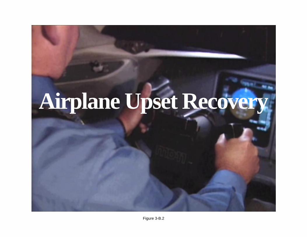
Airplane Upset Recovery
Figure 3-B.2
APPENDIX 3-B
Airplane Upset Recovery Briefing
Upsets have been attributed to environment, equipment, and pilot factors. The data also suggest that pilots need to bebetter prepared to cope with airplane upsets. Research by operators has indicated that most airline pilots rarely experienceairplane upsets, and many have never been trained in maximum performance maneuvers.
Page 3-B.3
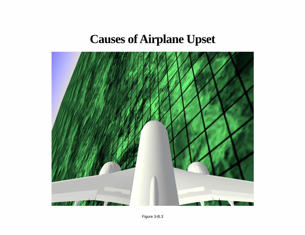
Causes of Airplane Upset
Figure 3-B.3

APPENDIX 3-B
Airplane Upset Recovery Briefing
Airplane upsets that are caused by environmental factors are difficult to predict; therefore, training programs stressavoidance of such phenomena. Complete avoidance is not possible, as the statistics suggest; therefore, the logicalconclusion is that pilots should be trained to safely recover an airplane that has been upset.
Page 3-B.4
Airplane Upset Recovery
Figure 3-B.4
APPENDIX 3-B
Airplane Upset Recovery Briefing
The goal of an Upset Recovery Training Program is twofold:
• To increase the pilot’s ability to recognize and avoid upset situations.
• To improve the pilot’s ability to recover control, if avoidance is not successful.
Page 3-B.5
Upset Recovery Training Objectives
• To increase the pilot’s ability to recognize andavoid upset situations.
• To improve the pilot’s ability to recover control,if avoidance is not successful.
Figure 3-B.5
APPENDIX 3-B
Airplane Upset Recovery Briefing
This briefing, as part of the overall Upset Recovery Training Program, is presented in three parts:
• The causes of airplane upsets.
• A brief review of swept-wing airplane fundamentals.
• Airplane upset recovery techniques.
Page 3-B.6

Upset Recovery Training Will Overview
• The causes of airplane upsets
• Swept-wing airplane fundamentals
• Airplane upset recovery techniques
Figure 3-B.6

APPENDIX 3-B
Airplane Upset Recovery Briefing
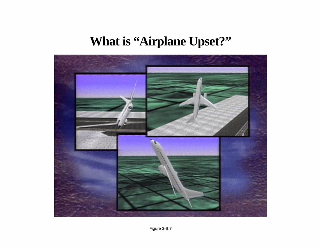
For discussion purposes, the following unintentional conditions generally describe an airplane upset:
• Pitch attitude greater than 25 deg nose up.
• Pitch attitude greater than 10 deg nose down.
• Bank angle greater than 45 deg.
• Within the above parameters, but flying at airspeeds inappropriate for the conditions.
Page 3-B.7
What is “Airplane Upset?”
Figure 3-B.7
APPENDIX 3-B
Airplane Upset Recovery Briefing
Causes of Airplane Upset Incidents Are Varied
The causes of airplane upset incidents are varied; however, they can be broken down into four broad categories.They can be
• Environmentally induced.
• Systems anomalies induced.
• Pilot induced.
• A combination of causes.
Page 3-B.8
Causes of Airplane Upset Incidents Are
• Environmentally induced
• Systems anomalies induced
• Pilot induced
• A combination of all three
Figure 3-B.8
APPENDIX 3-B
Airplane Upset Recovery Briefing
Environmentally Induced Airplane Upsets Include
• Turbulence.
• Windshear.
• Clear air turbulence.
• Mountain wave.
• Thunderstorms.
• Microbursts.
• Wake turbulence.
• Airplane icing.
Page 3-B.9
Environmental Causes of Airplane Upset Include
• Turbulence
• Clear air turbulence
• Mountain wave
• Thunderstorms
• Windshear
• Microbursts
• Wake turbulence
• Airplane icing
Figure 3-B.9
APPENDIX 3-B
Airplane Upset Recovery Briefing
Turbulence
Turbulence is characterized by a large variation in an air current over a short distance. It is mainly caused by
• Jet streams.
• Convective currents.
• Obstructions to wind flow.
• Windshear.
Knowledge of the various types of turbulence assists in avoiding it and, therefore, the potential for an airplane upset.
Page 3-B.10
• Jet streams
• Convective currents
• Obstructions to wind flow
• Windshear
Turbulence Is Primarily Caused by
Figure 3-B.10
APPENDIX 3-B
Airplane Upset Recovery Briefing
Clear Air Turbulence (CAT)
Clear air turbulence (CAT) is defined as “high-level turbulence”, as it is normally above 15,000 MSL. It is not associatedwith cumuliform cloudiness, including thunderstorms. CAT is almost always present near jet streams. Jet streams aredynamic, and turbulence associated with them is difficult to predict. The area of turbulence can be 100 to 300 mi long—50 to 100 mi wide—and 2000 to 5000 ft thick.
Page 3-B.11
• Pressure
• Temperature
• Wind direction
• Wind velocity
Clear Air Turbulence (CAT) Is Characterizedby Marked Changes in
Figure 3-B.11

APPENDIX 3-B
Airplane Upset Recovery Briefing
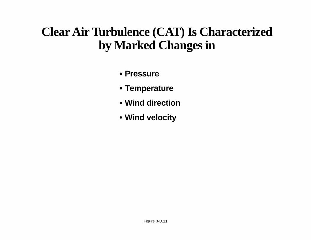
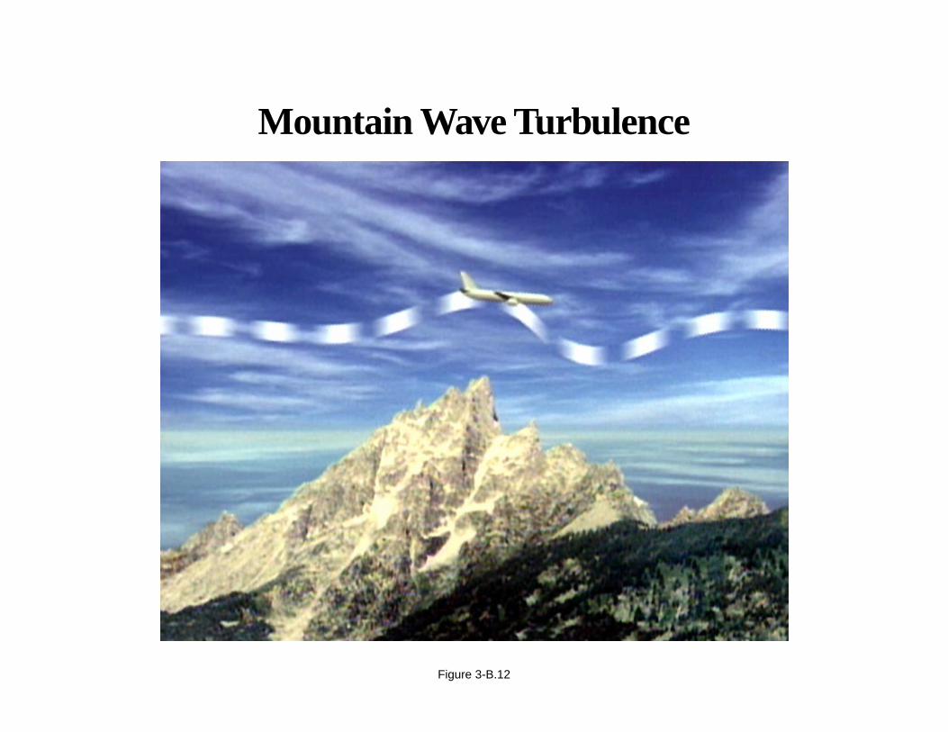
Mountain Wave
Mountains are the greatest obstructions to wind flow. Therefore, this type of turbulence is classified as “mechanical.”Rotor or lenticular clouds over mountains are a sure sign of Mountain Wave Turbulence, but unfortunately the air maybe too dry for the presence of the telltale clouds. Severe turbulence can be expected in mountainous areas, if theperpendicular wind component exceeds 50 kn.
Page 3-B.12
Mountain Wave Turbulence
Figure 3-B.12
APPENDIX 3-B
Airplane Upset Recovery Briefing
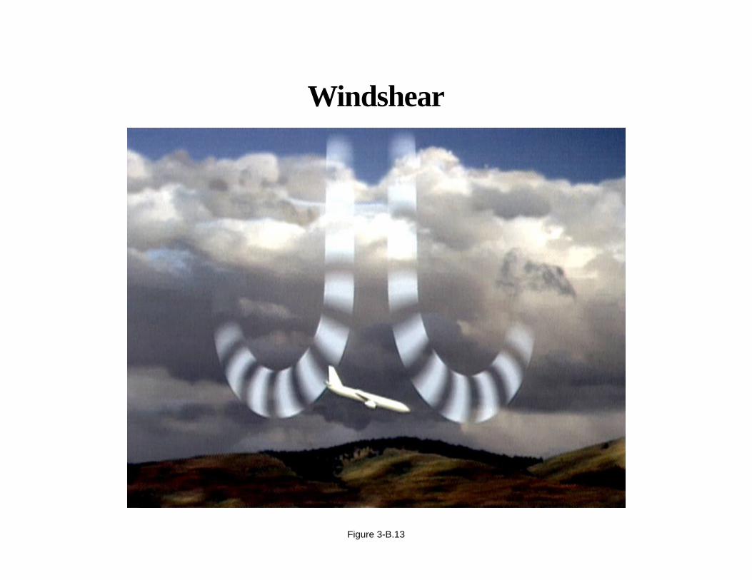
Windshear
Wind variations at low altitude are recognized as a serious hazard to airplanes during takeoff and approach. Thesevariations can be caused by many differing meteorological conditions:
• Topographical.
• Temperature inversions.
• Sea breezes.
• Frontal systems.
• Strong surface winds.
• Thunderstorms.
• Rain showers.
The latter two, thunderstorms and rain showers, are the two most violent forms of wind change, and they will be discussedin more detail.
Page 3-B.13
Windshear
Figure 3-B.13
APPENDIX 3-B
Airplane Upset Recovery Briefing
Thunderstorms
There are two basic types of thunderstorms: airmass and frontal.
Airmass thunderstorms are randomly distributed in unstable air. Heated air rises to form cumulus clouds. The cloudsdevelop in three stages: cumulus stage; mature stage; dissipating stage. The gust front produced by the downflow andout-rush of rain-cooled air can produce very turbulent air conditions.
Frontal thunderstorms are associated with weather system line fronts, converging wind, and troughs aloft. Frontalthunderstorms form in squall lines; last several hours; generate heavy rain, and possibly hail; and produce strong gustywinds, and possibly tornadoes. The downdraft of a typical frontal thunderstorm is large, about 1 to 5 miles in diameter.Resultant outflows may produce large changes in windspeed.
Page 3-B.14

Thunderstorms
Figure 3-B.14

APPENDIX 3-B
Airplane Upset Recovery Briefing
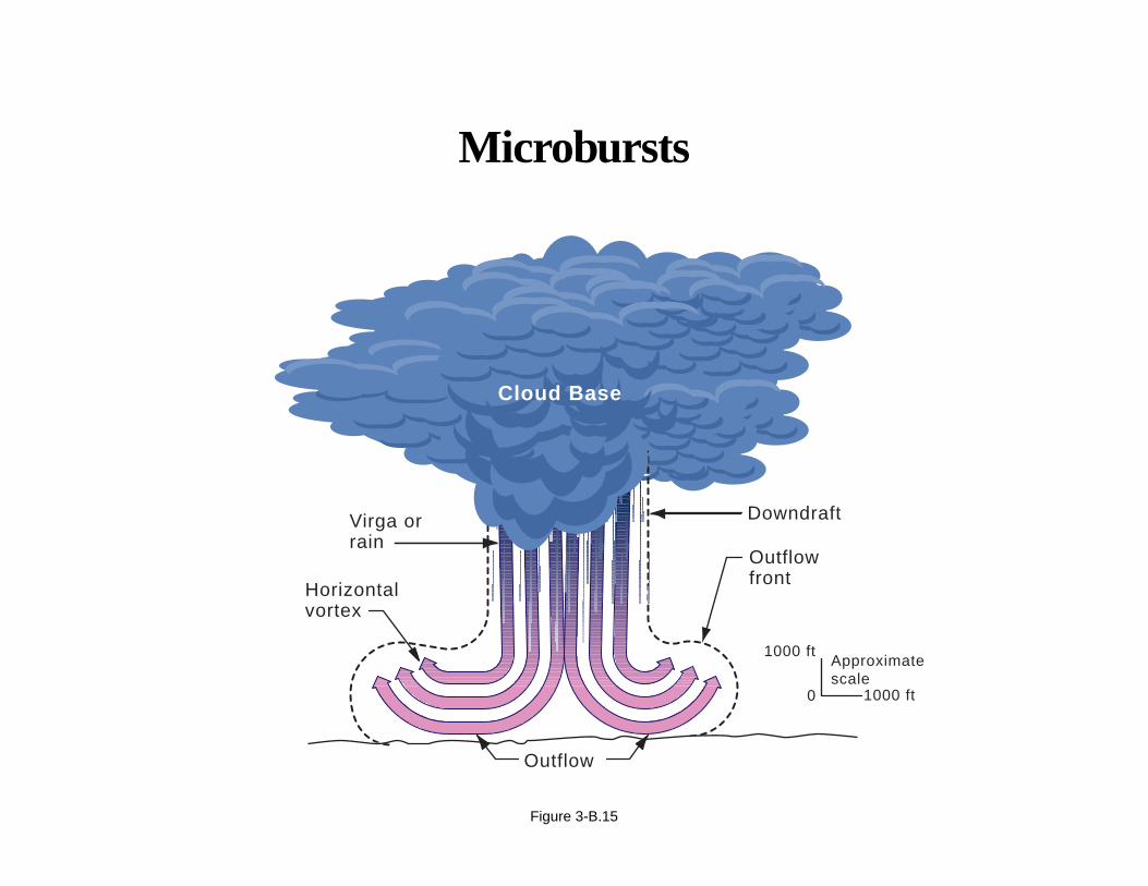
Microbursts
Microbursts can occur anywhere convective weather conditions occur. Five percent of all thunderstorms producemicrobursts. Downdrafts are typically only a few hundred to 3000 ft across. The outflows are not always symmetrical.A significant airspeed increase may not occur upon entering outflows, or it may be much less than the subsequentairspeed loss experienced when exiting. It is vital to recognize that some microbursts cannot be successfully escapedwith any known techniques.
Page 3-B.15
Microbursts
Figure 3-B.15
DowndraftVirga or rain
Horizontalvortex
Outflowfront
Outflow
1000 ftApproximatescale
1000 ft0
Cloud Base
APPENDIX 3-B
Airplane Upset Recovery Briefing
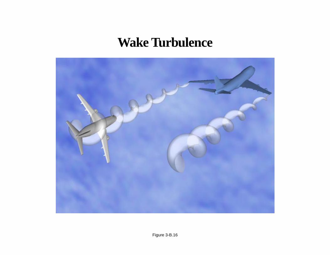
Wake Turbulence
Wake turbulence is the leading cause of airplane upsets that are environmentally induced. A pair of counter-rotatingvortices is shed from an airplane wing, thus causing turbulence in the airplane’s wake. The strength of the turbulenceis a function of airplane weight, wingspan, and speed. Vortices descend at an initial rate of 300 to 500 ft/min for about30 sec. The descent rate decreases and eventually approaches zero at 500 to 900 ft below the flight path. Avoidance canbe accomplished by flying above the offender’s flight path. Maintaining a vertical separation of at least 1000 ft belowthe flight path is also considered safe. Pilots have likened a wake-turbulence encounter to be like “hitting a wall.”Counter-control is usually effective.
Page 3-B.16
Wake Turbulence
Figure 3-B.16
APPENDIX 3-B
Airplane Upset Recovery Briefing
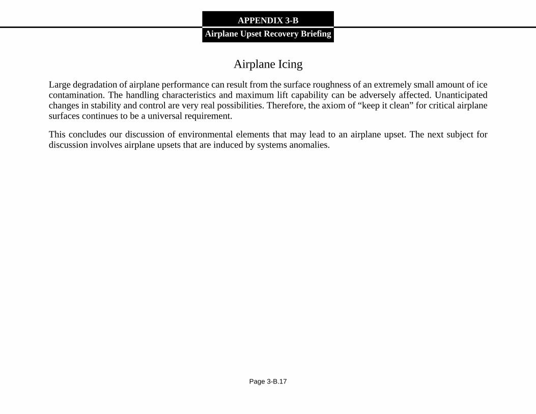
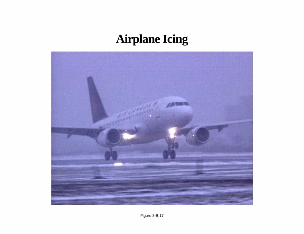
Airplane Icing
Large degradation of airplane performance can result from the surface roughness of an extremely small amount of icecontamination. The handling characteristics and maximum lift capability can be adversely affected. Unanticipatedchanges in stability and control are very real possibilities. Therefore, the axiom of “keep it clean” for critical airplanesurfaces continues to be a universal requirement.
This concludes our discussion of environmental elements that may lead to an airplane upset. The next subject fordiscussion involves airplane upsets that are induced by systems anomalies.
Page 3-B.17
Airplane Icing
Figure 3-B.17

APPENDIX 3-B
Airplane Upset Recovery Briefing
Systems-Anomalies-Induced Airplane Upsets
The discussion will include
• Flight instruments.
• Autoflight systems.
• Flight controls and other anomalies.
Page 3-B.18
System-Anomalies-Induced AirplaneUpsets Primarily Involve
• Flight instruments
• Autoflight systems
• Flight controls and other anomalies
Figure 3-B.18
APPENDIX 3-B
Airplane Upset Recovery Briefing
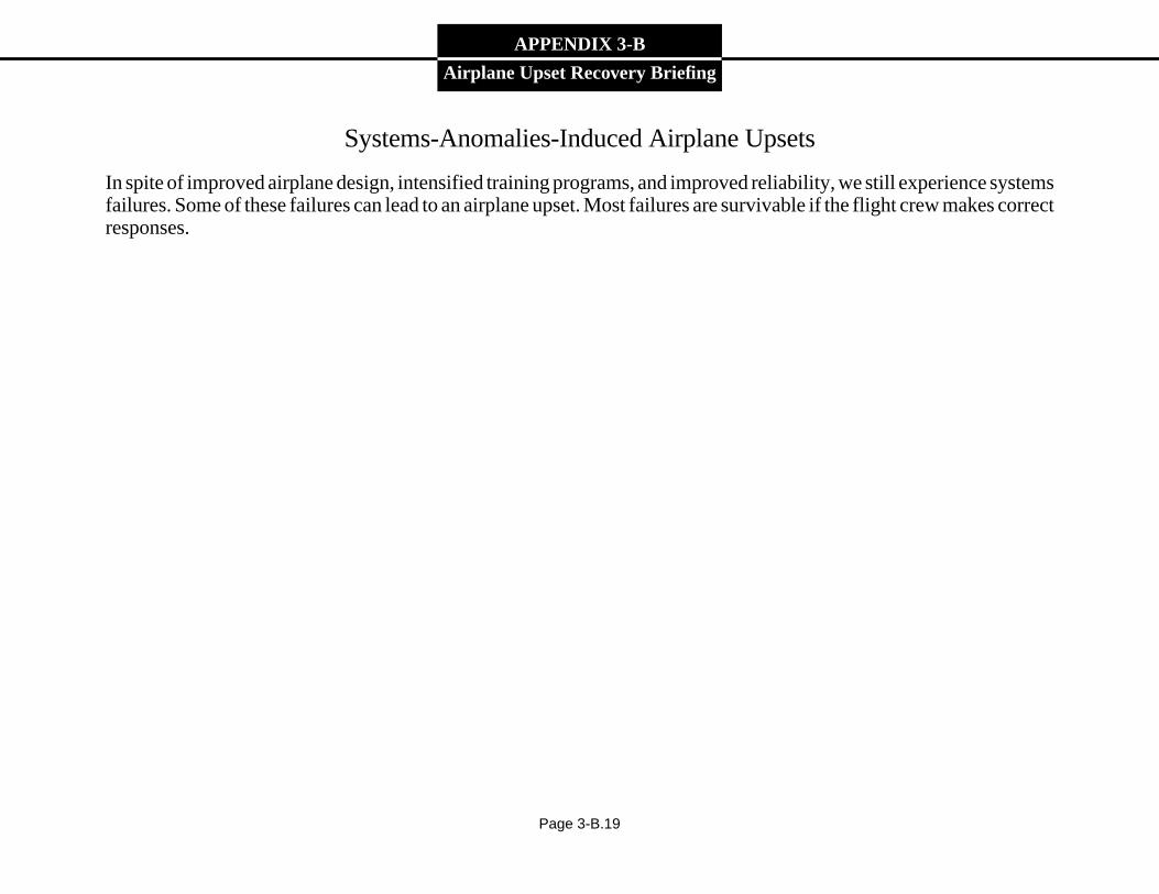
Systems-Anomalies-Induced Airplane Upsets
In spite of improved airplane design, intensified training programs, and improved reliability, we still experience systemsfailures. Some of these failures can lead to an airplane upset. Most failures are survivable if the flight crew makes correctresponses.
Page 3-B.19
System-Anomalies-Induced Airplane Upsets
Figure 3-B.19
APPENDIX 3-B
Airplane Upset Recovery Briefing
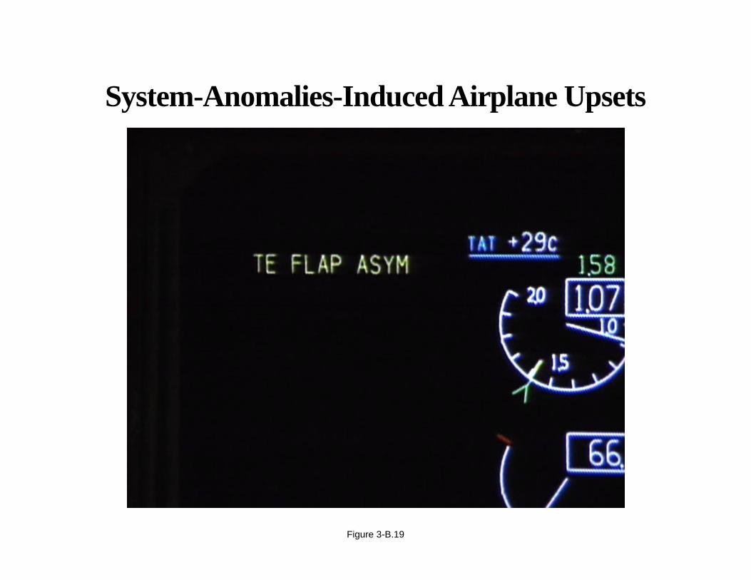
Flight Instruments
Instrument failures are infrequent, but they do occur. All airplane operations manuals provide flight instrument systeminformation, such that when instrument failures do occur, the pilot can analyze the impact and select the correctprocedural alternatives. Airplane certification requires that pilots have the minimum information needed to safelycontrol the airplane, in the event of instrument failure. Several accidents point out that pilots are not always preparedto correctly analyze the alternatives in case of failure. The result is an airplane upset.
Page 3-B.20
Flight Instruments
Figure 3-B.20
APPENDIX 3-B
Airplane Upset Recovery Briefing
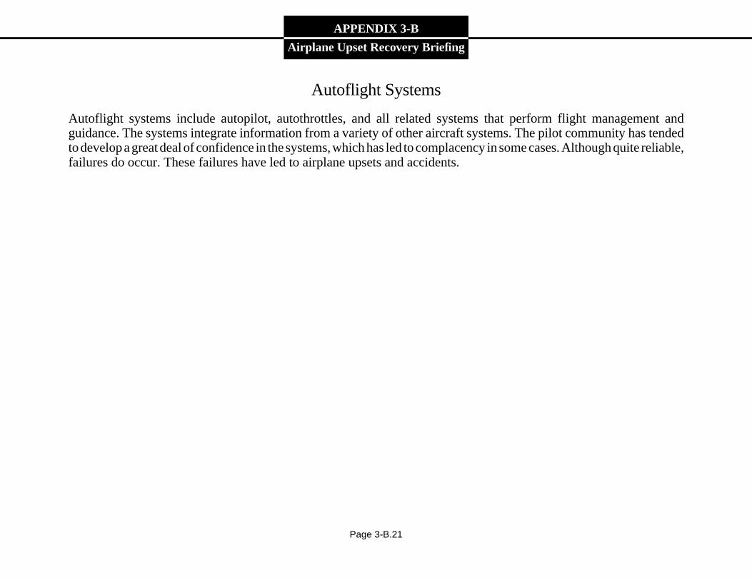
Autoflight Systems
Autoflight systems include autopilot, autothrottles, and all related systems that perform flight management andguidance. The systems integrate information from a variety of other aircraft systems. The pilot community has tendedto develop a great deal of confidence in the systems, which has led to complacency in some cases. Although quite reliable,failures do occur. These failures have led to airplane upsets and accidents.
Page 3-B.21
Autoflight Systems
Figure 3-B.21
APPENDIX 3-B
Airplane Upset Recovery Briefing
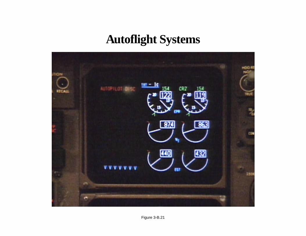
Flight Control and Other Anomalies
Flap asymmetry, spoiler problems, and other flight control anomalies are addressed in airplane operations manuals.Airplane certification requirements ensure that pilots have sufficient information and are trained to handle these criticalfailures. However, it is the unexpected that can cause problems, particularly during critical phases of flight.
Page 3-B.22
Flight Control and Other Anomalies
Figure 3-B.22
APPENDIX 3-B
Airplane Upset Recovery Briefing
Pilot-Induced Airplane Upsets
We have known for many years that sensory inputs can be misleading to pilots, especially when pilots cannot see thehorizon. To solve this problem, airplanes are equipped with flight instruments to provide the necessary information forcontrolling the airplane. Subjects for discussion in this area include
• Instrument cross-check.
• Inattention and distraction from primary cockpit duties.
• Vertigo or spatial disorientation.
• Improper use of airplane automation.
Page 3-B.23
Pilot-Induced Causes of Airplane Upset Include
• Instrument misinterpretation or slow cross-check
• Inattention and distraction from primary cockpit duties
• Vertigo or spatial disorientation
• Improper use of airplane automation
Figure 3-B.23
APPENDIX 3-B
Airplane Upset Recovery Briefing
Instrument Cross-Check
Instrument misinterpretation or a slow cross-check can lead to an airplane upset. Many of the minor upsets can be tracedto an improper instrument cross-check. However, a good cross-check and proper interpretation is only one part of theequation. It is necessary for the pilot to make the correct adjustments to pitch, bank, and power in order to control theairplane.
Page 3-B.24
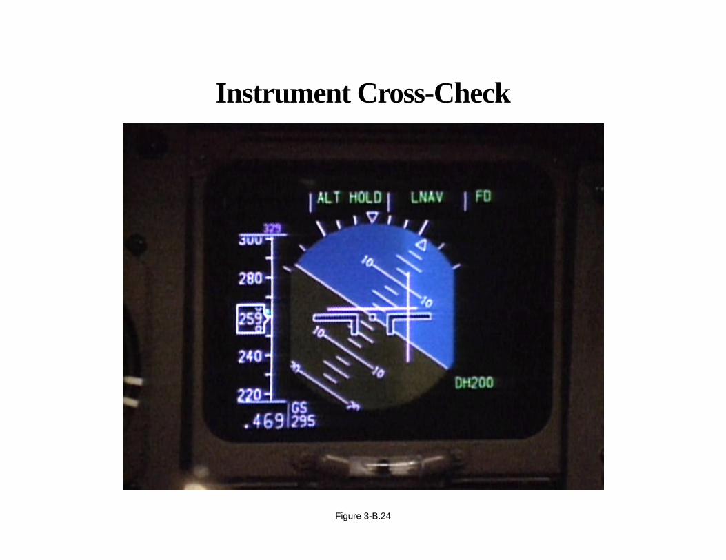
Instrument Cross-Check
Figure 3-B.24
APPENDIX 3-B
Airplane Upset Recovery Briefing
Inattention or Distraction from Primary Cockpit Duties
A review of airplane upsets reveals that inattention or neglecting to monitor the airplane’s performance can lead toextreme deviations from the normal flight envelope. Neglecting to monitor all the instruments or fixating on a certaininstrument can lead to performance deviations. Distractions can be very subtle, such as warning or caution lightsilluminating during critical phases of flight. Many airplane upsets occur while the pilot is engaged in some task that takesattention away from the flight instruments. “Control the airplane first” should always be the guiding principle.
Page 3-B.25

Distraction
Figure 3-B.25
APPENDIX 3-B
Airplane Upset Recovery Briefing
Vertigo or Spatial Disorientation
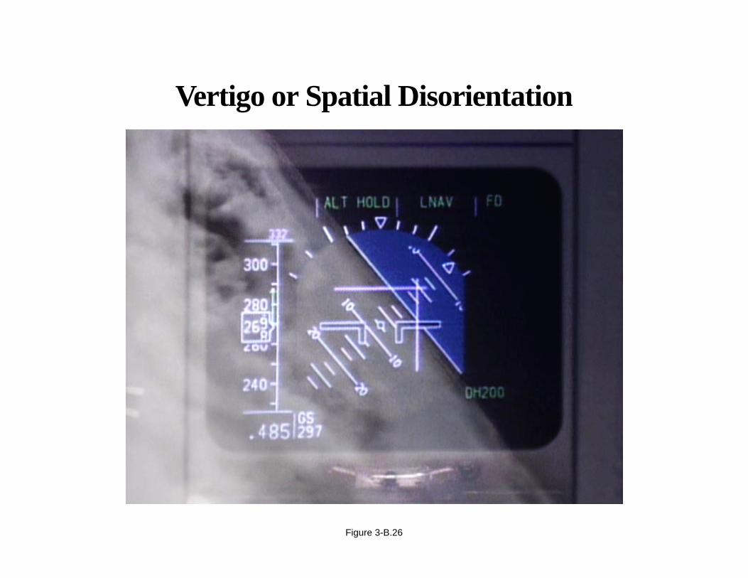
Spatial disorientation has been a significant factor in many airplane-upset accidents. The definition of spatialdisorientation is the inability to correctly orient oneself with respect to the Earth’s surface. We are all susceptible tosensory illusions. Pilots who perceive a conflict between bodily senses and the flight instruments and are unable toresolve the conflict are spatially disorientated. Allowed to continue, spatial disorientation will lead to airplane upset.Attention to flight instruments and a good cross-check are the keys to remaining spatially orientated.
Page 3-B.26
Vertigo or Spatial Disorientation
Figure 3-B.26

APPENDIX 3-B
Airplane Upset Recovery Briefing
Improper Use of Airplane Automation
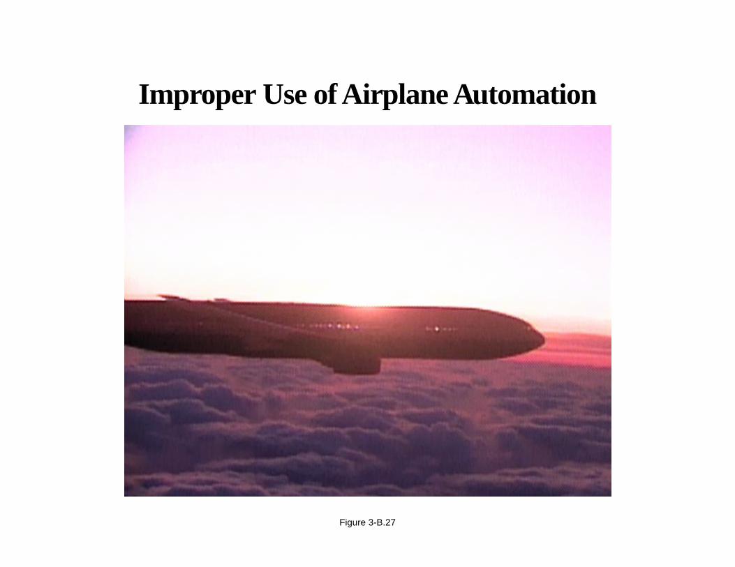
The advancement of technology in today’s modern airplanes has brought us flight directors, autopilots, autothrottles,and flight management systems. When used properly, this technology contributes to flight safety and reduces crewworkload. Complacent and improper use of these systems is a concern. The systems can and do fail, leading to airplaneupsets and accidents.
Page 3-B.27
Improper Use of Airplane Automation
Figure 3-B.27
APPENDIX 3-B
Airplane Upset Recovery Briefing
Causes of Airplane Upsets—Summary
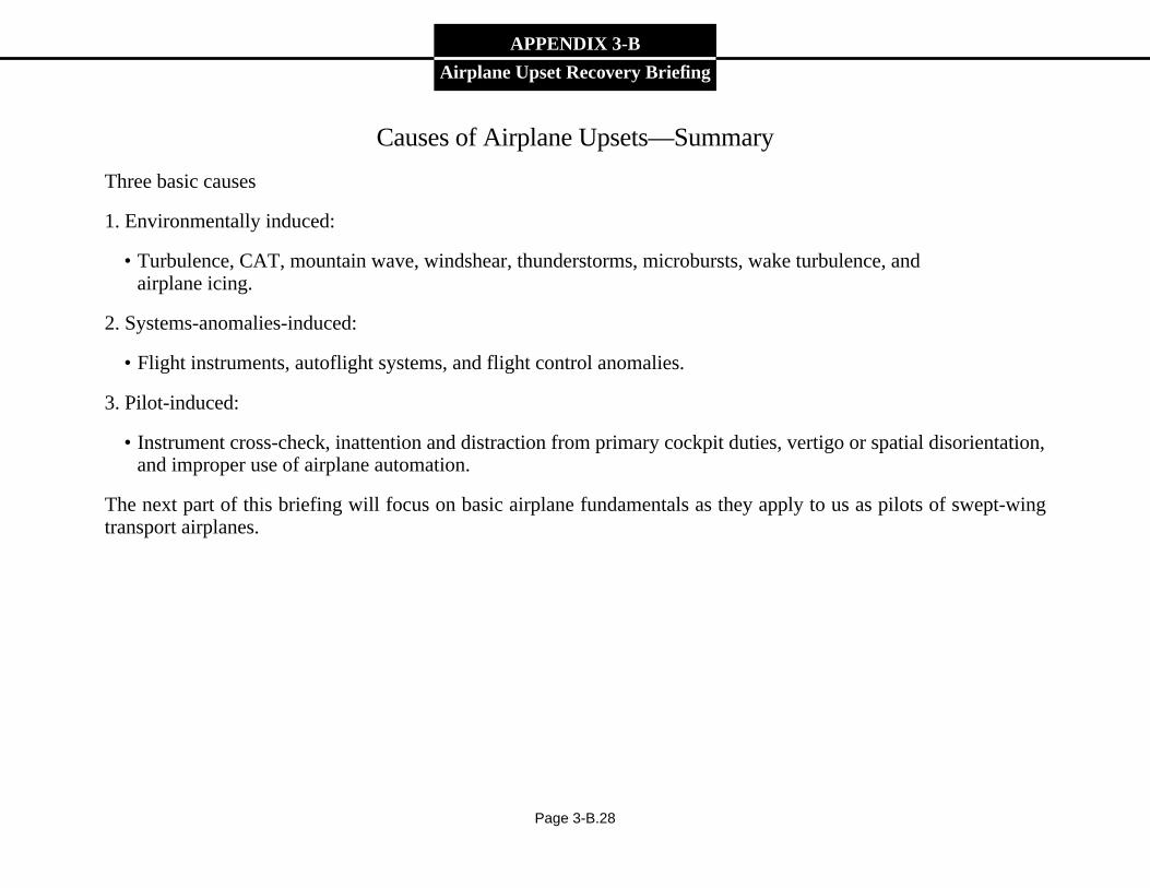
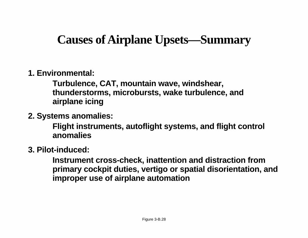
Three basic causes
1. Environmentally induced:
• Turbulence, CAT, mountain wave, windshear, thunderstorms, microbursts, wake turbulence, andairplane icing.
2. Systems-anomalies-induced:
• Flight instruments, autoflight systems, and flight control anomalies.
3. Pilot-induced:
• Instrument cross-check, inattention and distraction from primary cockpit duties, vertigo or spatial disorientation,and improper use of airplane automation.
The next part of this briefing will focus on basic airplane fundamentals as they apply to us as pilots of swept-wingtransport airplanes.
Page 3-B.28
Causes of Airplane Upsets—Summary
1. Environmental:Turbulence, CAT, mountain wave, windshear,thunderstorms, microbursts, wake turbulence, andairplane icing
2. Systems anomalies:Flight instruments, autoflight systems, and flight controlanomalies
3. Pilot-induced:Instrument cross-check, inattention and distraction fromprimary cockpit duties, vertigo or spatial disorientation, andimproper use of airplane automation
Figure 3-B.28
APPENDIX 3-B
Airplane Upset Recovery Briefing
Swept-Wing Airplane Fundamentals for Pilots
The areas of interest include
• Flight dynamics.
• Energy states.
• Load factors.
• Aerodynamic flight envelope.
• Aerodynamics.
Page 3-B.29
Swept-Wing Airplane FundamentalsWill Overview
• Flight dynamics
• Energy states
• Load factors
• Aerodynamic flight envelope
• Aerodynamics
Figure 3-B.29
APPENDIX 3-B
Airplane Upset Recovery Briefing
Flight Dynamics
In understanding the flight dynamics of large, swept-wing transport airplanes, it is important to first understand whatcauses the forces and moments acting on the airplane and then move to what kinds of motion these forces cause. Withthis background, we can gain an understanding of how a pilot can control these forces and moments in order to directthe flight path.
Newton’s first law states that an object at rest will tend to stay at rest, and an object in motion will tend to stay in motionin a straight line, unless acted on by an external force. If an airplane in motion is to deviate from a straight line, theremust be a force, or a combination of forces, imposed to achieve the desired trajectory. The generation of the forces isthe subject of aerodynamics (to be discussed later). The generation of forces requires energy, which for discussionpurposes can be called “energy state.”
Page 3-B.30

Flight Dynamics
Figure 3-B.30
APPENDIX 3-B
Airplane Upset Recovery Briefing
Energy States
The term “energy state” describes how much of each kind of energy the airplane has available at any given time. Pilotswho understand the airplane energy state will be in a position to know instantly what options they may have to maneuvertheir airplane.
The three sources of energy available to the pilot are
1. Kinetic energy, which increases with increasing airspeed.
2. Potential energy, which is approximately proportional to altitude.
3. Chemical energy, from the fuel in the tanks.
Page 3-B.31

The Three Sources of EnergyAvailable to the Pilot Are
1. Kinetic energy, which increases with increasing speed
2. Potential energy, which is approximately proportional to altitude
3. Chemical energy, from the fuel in tanks
Figure 3-B.31
APPENDIX 3-B
Airplane Upset Recovery Briefing
Energy States (continued)
During maneuvering, these three types of energy can be traded, or exchanged, usually at the cost of additional drag. Therelationships are shown here:
• Airspeed can be traded for altitude, and altitude can be traded for airspeed.
• Stored energy can be traded for either altitude or airspeed.
Modern high-performance, jet transport airplanes have low drag characteristics in cruise configuration; therefore, thepilot needs to exercise considerable judgement in making very large energy trades. A clean airplane operating near itslimits can easily go from the low-speed boundary to and through the high-speed boundary very quickly. The process ofcontrolling forces to change accelerations and produce a new energy state takes time. The longer time required by largeairplanes requires that the pilot plan ahead—that much more—to achieve the final desired energy state. The objectiveis to manage energy so that kinetic energy stays between limits (stall and placards), the potential energy stays with limits(terrain to buffet altitude), and chemical energy stays above certain thresholds (not running out of fuel).
Page 3-B.32
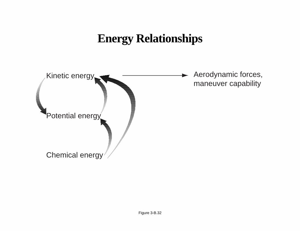
Energy Relationships
Figure 3-B.32
Aerodynamic forces,maneuver capability
Potential energy
Chemical energy
Kinetic energy
APPENDIX 3-B
Airplane Upset Recovery Briefing
Load Factors
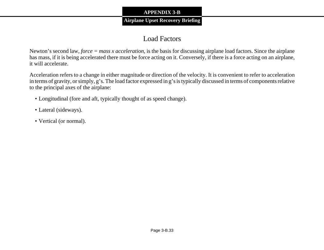
Newton’s second law, force = mass x acceleration, is the basis for discussing airplane load factors. Since the airplanehas mass, if it is being accelerated there must be force acting on it. Conversely, if there is a force acting on an airplane,it will accelerate.
Acceleration refers to a change in either magnitude or direction of the velocity. It is convenient to refer to accelerationin terms of gravity, or simply, g’s. The load factor expressed in g’s is typically discussed in terms of components relativeto the principal axes of the airplane:
• Longitudinal (fore and aft, typically thought of as speed change).
• Lateral (sideways).
• Vertical (or normal).
Page 3-B.33
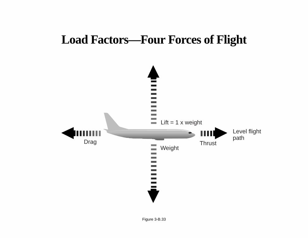
Load Factors—Four Forces of Flight
Figure 3-B.33
Drag Thrust
Lift = 1 x weight
Weight
Level flightpath
APPENDIX 3-B
Airplane Upset Recovery Briefing
Load Factors (continued)
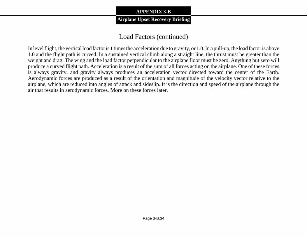
In level flight, the vertical load factor is 1 times the acceleration due to gravity, or 1.0. In a pull-up, the load factor is above1.0 and the flight path is curved. In a sustained vertical climb along a straight line, the thrust must be greater than theweight and drag. The wing and the load factor perpendicular to the airplane floor must be zero. Anything but zero willproduce a curved flight path. Acceleration is a result of the sum of all forces acting on the airplane. One of these forcesis always gravity, and gravity always produces an acceleration vector directed toward the center of the Earth.Aerodynamic forces are produced as a result of the orientation and magnitude of the velocity vector relative to theairplane, which are reduced into angles of attack and sideslip. It is the direction and speed of the airplane through theair that results in aerodynamic forces. More on these forces later.
Page 3-B.34
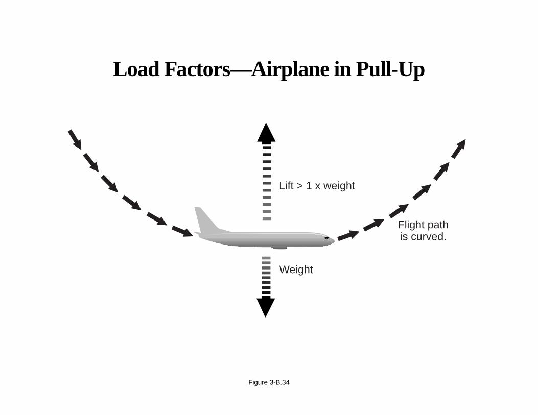
Load Factors—Airplane in Pull-Up
Figure 3-B.34
Weight
Flight pathis curved.
Lift > 1 x weight
APPENDIX 3-B
Airplane Upset Recovery Briefing
Aerodynamic Flight Envelope
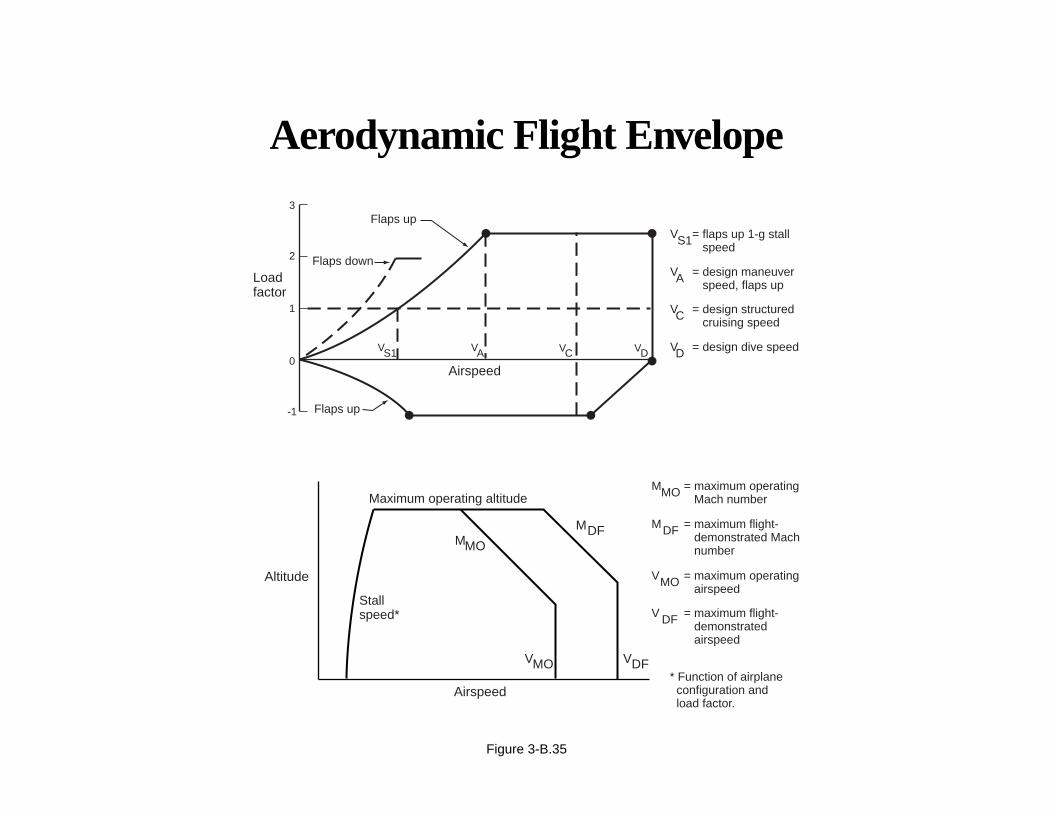
Current jet transport airplanes are certificated to withstand normal vertical load factors from -1.0 to 2.5 g in the cruiseconfiguration. In addition to the strength of the structure, the handling qualities are demonstrated to be safe within theselimits of load factors. The pilot should be able to maneuver safely to and from these load factors at these speeds, withoutneeding exceptional strength or skills. Test pilots have evaluated the characteristics of airplanes in conditions that includeinadvertent exceedances of these operational envelopes to demonstrate that the airplanes can be returned safely to theoperational envelopes. This slide depicts a typical flight envelope, but it also shows the maximum demonstrated Machand speed numbers. These are typically 0.05 to 0.07 Mach and 50 kn higher than the operational limits. Safe flightcharacteristics to return to the normal operational envelope must be demonstrated.
Page 3-B.35
Aerodynamic Flight Envelope
Figure 3-B.35
Maximum operating altitude
Stallspeed*
Altitude
Airspeed
MDF
VDFVMO
MMO
MMO
MDF
VMO
V DF
= maximum operatingMach number
= maximum flight-demonstrated Machnumber
= maximum operatingairspeed
= maximum flight-demonstratedairspeed
* Function of airplane configuration and load factor.
Airspeed
Loadfactor
-1
0
1
2
3
Flaps down
Flaps up
Flaps up
S1 A C D
VS1
VA
VC
VD
= flaps up 1-g stallspeed
= design maneuverspeed, flaps up
= design structuredcruising speed
= design dive speedV V V V
APPENDIX 3-B
Airplane Upset Recovery Briefing
Angle of Attack and Stall
Wing and tail surfaces all produce lift forces in the same way. The lift force generated by a surface is a function of theangle of attack, the dynamic pressure (proportional to the air density and the square of the true airspeed) of the air movingaround it, and the size of the surface. It is important to understand the dependence of lift on angle of attack. As angleof attack is increased, lift increases proportionally up to the point where the air starts to separate from the wing. At thiscritical angle of attack, the airflow breaks down and the surface is stalled. This is true regardless of airplane speed oraltitude. Angle of attack can sometimes be confusing.
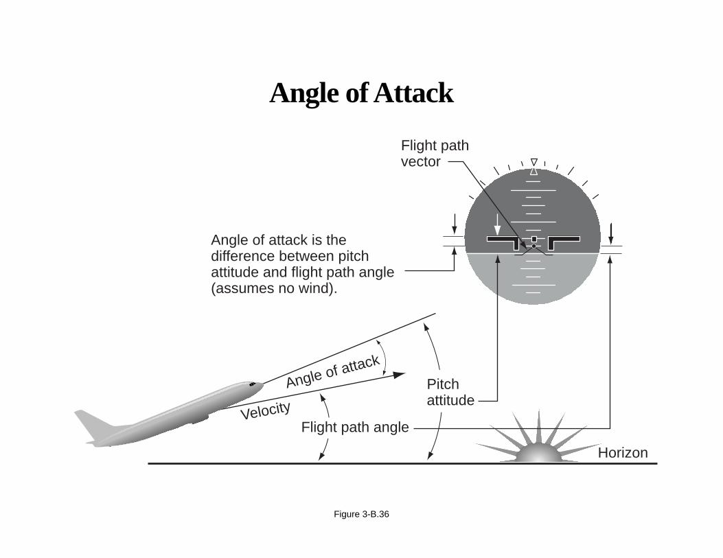
The three angles usually referred to in the longitudinal axis are
• Angle of attack.
• Flight path angle.
• Pitch angle.
These three angles and their relationships to each other are shown here. Depending on the context in which it is used,aerodynamicists use the term “angle of attack” in a number of different ways. Angle of attack is always the angle betweenthe oncoming air or relative wind, and some reference line on the airplane or wing. Sometimes it is referenced to the chordline at a particular location on the wing, sometimes to an “average” chord line on the wing, other times it is referencedto a convenient reference line on the airplane, like the body reference x axis. Regardless of the reference, the conceptis the same as are the consequences: exceed the critical angle of attack and the lifting surfaces and wind will separate,resulting in a loss of lift on those surfaces. Frequently the term “airplane angle of attack” is used to refer to the anglebetween the relative wind and the longitudinal axis of the airplane. In flight dynamics, this is frequently reduced to simply“angle of attack.” It is also the difference between the pitch angle and the flight path angle in a no-wind condition.
Page 3-B.36
Angle of Attack
Figure 3-B.36
Horizon
Velocity
Angle of attack
Angle of attack is thedifference between pitchattitude and flight path angle(assumes no wind).
Pitchattitude
Flight path angle
Flight pathvector
APPENDIX 3-B
Airplane Upset Recovery Briefing
Angle of Attack and Stall (continued)
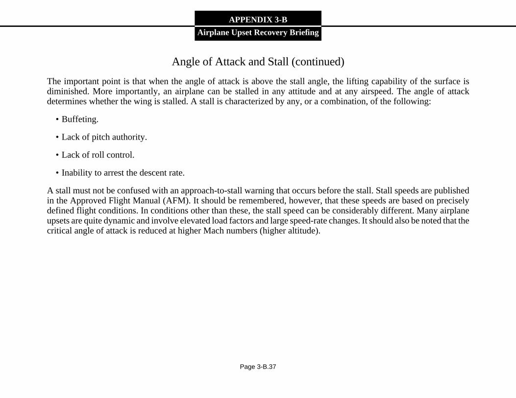
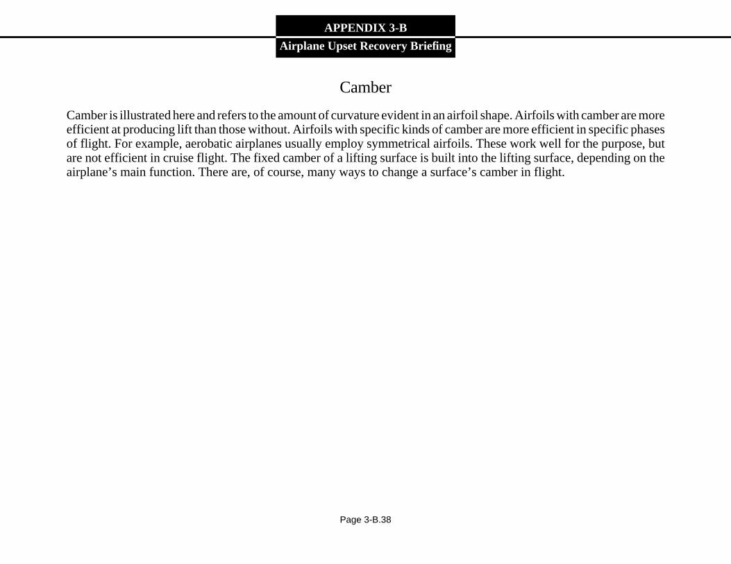
The important point is that when the angle of attack is above the stall angle, the lifting capability of the surface isdiminished. More importantly, an airplane can be stalled in any attitude and at any airspeed. The angle of attackdetermines whether the wing is stalled. A stall is characterized by any, or a combination, of the following:
• Buffeting.
• Lack of pitch authority.
• Lack of roll control.
• Inability to arrest the descent rate.
A stall must not be confused with an approach-to-stall warning that occurs before the stall. Stall speeds are publishedin the Approved Flight Manual (AFM). It should be remembered, however, that these speeds are based on preciselydefined flight conditions. In conditions other than these, the stall speed can be considerably different. Many airplaneupsets are quite dynamic and involve elevated load factors and large speed-rate changes. It should also be noted that thecritical angle of attack is reduced at higher Mach numbers (higher altitude).
Page 3-B.37
Stalls
Figure 3-B.37
APPENDIX 3-B
Airplane Upset Recovery Briefing
Camber
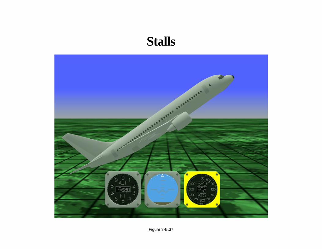
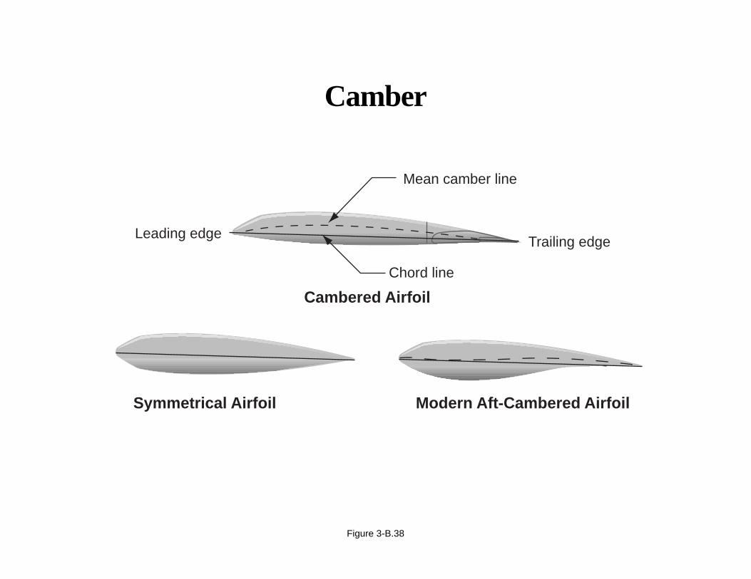
Camber is illustrated here and refers to the amount of curvature evident in an airfoil shape. Airfoils with camber are moreefficient at producing lift than those without. Airfoils with specific kinds of camber are more efficient in specific phasesof flight. For example, aerobatic airplanes usually employ symmetrical airfoils. These work well for the purpose, butare not efficient in cruise flight. The fixed camber of a lifting surface is built into the lifting surface, depending on theairplane’s main function. There are, of course, many ways to change a surface’s camber in flight.
Page 3-B.38
Camber
Figure 3-B.38
Symmetrical Airfoil Modern Aft-Cambered Airfoil
Cambered Airfoil
Trailing edge
Mean camber line
Chord line
Leading edge

APPENDIX 3-B
Airplane Upset Recovery Briefing
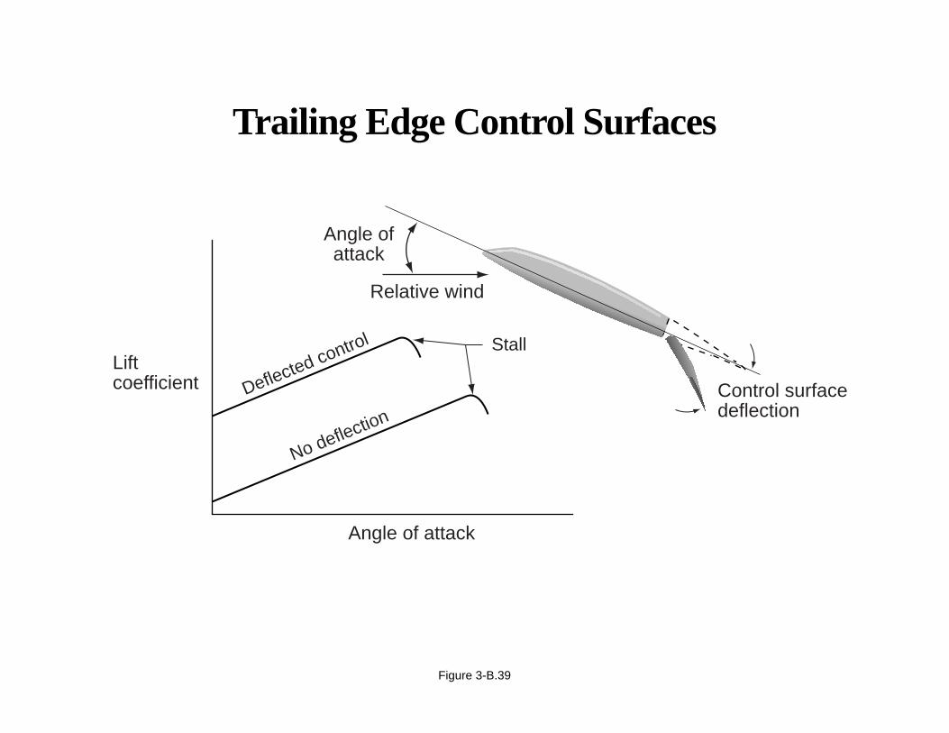
Control Surface Fundamentals
Trailing edge control surfaces provide a way of modulating the lift on a surface without physically changing thatsurface’s angle of attack. The aerodynamic effect is that of increasing the lift at a constant angle of attack for trailingedge down deflection. As you can see, the price paid is a reduced angle of attack for stall at higher deflection angles.Large downward aileron deflections, at very high angles of attack, could induce air separation over that portion of thewing. Reducing the angle of attack before making large aileron deflections will help ensure the effectiveness of thosesurfaces.
Page 3-B.39
Trailing Edge Control Surfaces
Figure 3-B.39
Control surfacedeflection
Liftcoefficient
Angle ofattack
Angle of attack
No deflection
Deflected control Stall
Relative wind
APPENDIX 3-B
Airplane Upset Recovery Briefing
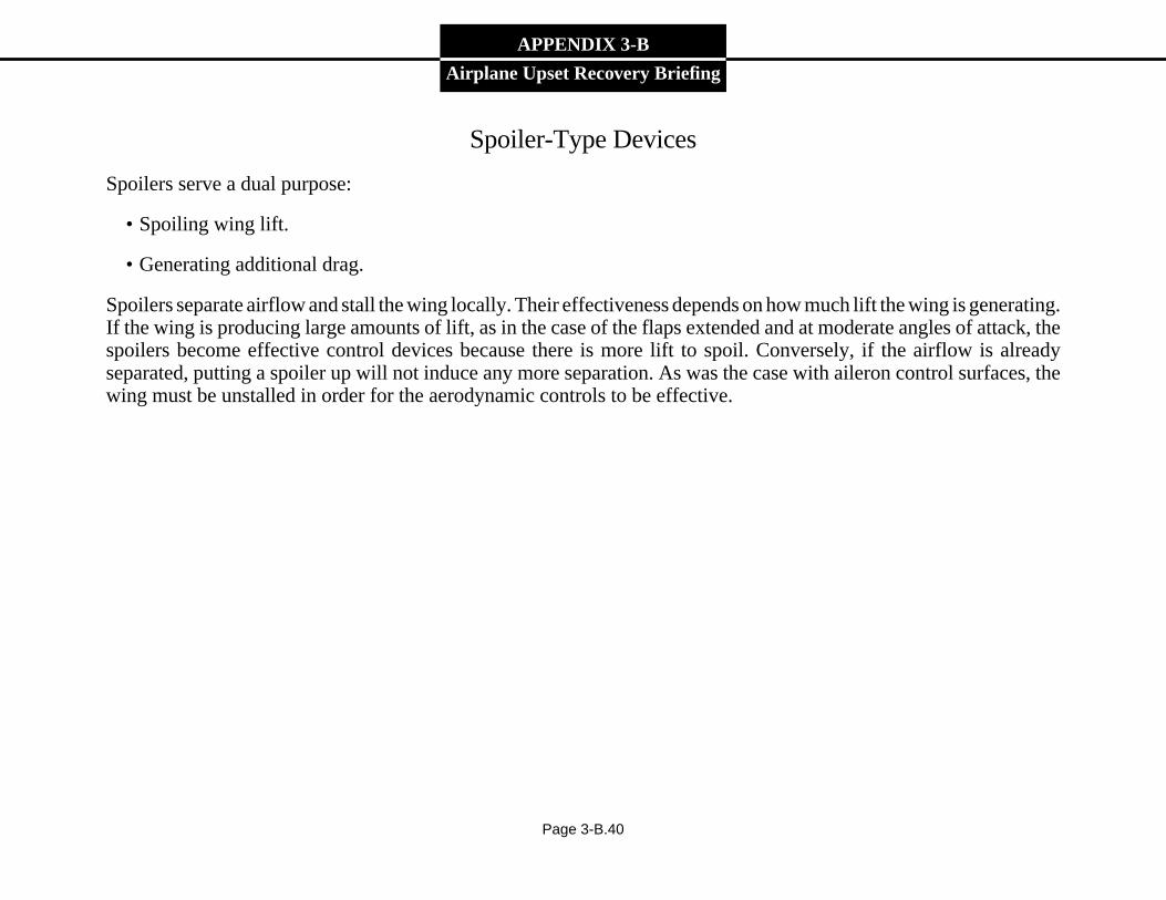
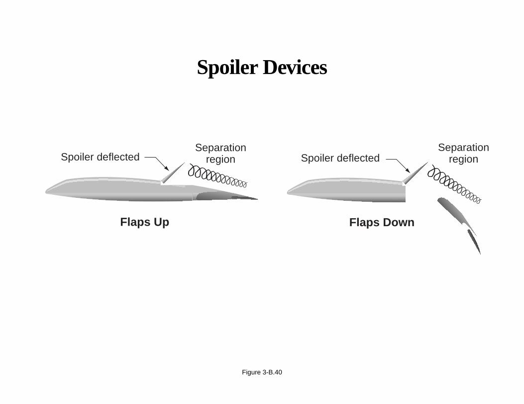
Spoiler-Type Devices
Spoilers serve a dual purpose:
• Spoiling wing lift.
• Generating additional drag.
Spoilers separate airflow and stall the wing locally. Their effectiveness depends on how much lift the wing is generating.If the wing is producing large amounts of lift, as in the case of the flaps extended and at moderate angles of attack, thespoilers become effective control devices because there is more lift to spoil. Conversely, if the airflow is alreadyseparated, putting a spoiler up will not induce any more separation. As was the case with aileron control surfaces, thewing must be unstalled in order for the aerodynamic controls to be effective.
Page 3-B.40
Spoiler Devices
Figure 3-B.40
Separationregion
Separationregion
Flaps Up Flaps Down
Spoiler deflectedSpoiler deflected
APPENDIX 3-B
Airplane Upset Recovery Briefing
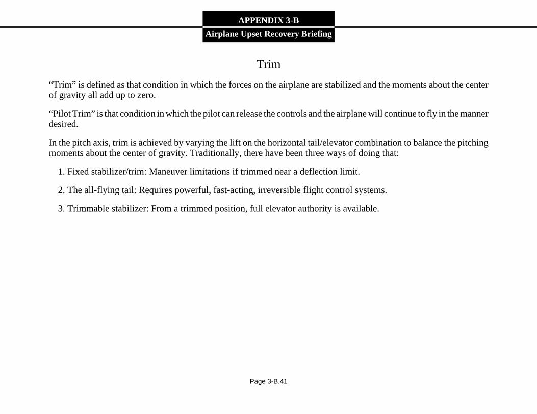
Trim
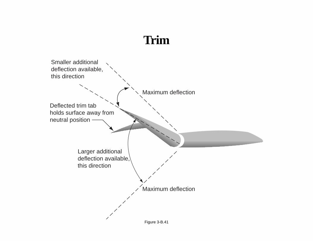
“Trim” is defined as that condition in which the forces on the airplane are stabilized and the moments about the centerof gravity all add up to zero.
“Pilot Trim” is that condition in which the pilot can release the controls and the airplane will continue to fly in the mannerdesired.
In the pitch axis, trim is achieved by varying the lift on the horizontal tail/elevator combination to balance the pitchingmoments about the center of gravity. Traditionally, there have been three ways of doing that:
1. Fixed stabilizer/trim: Maneuver limitations if trimmed near a deflection limit.
2. The all-flying tail: Requires powerful, fast-acting, irreversible flight control systems.
3. Trimmable stabilizer: From a trimmed position, full elevator authority is available.
Page 3-B.41
Trim
Figure 3-B.41
Maximum deflection
Smaller additionaldeflection available,this direction
Deflected trim tab holds surface away from neutral position
Larger additionaldeflection available,this direction
Maximum deflection
APPENDIX 3-B
Airplane Upset Recovery Briefing
Lateral and Directional Aerodynamic Considerations
The static lateral stability of an airplane involves consideration of rolling moments due to sideslip.
Aerodynamically, anti-symmetric flight, or flight in sideslip, can be quite complex. The forces and moments generatedby the sideslip can affect motion in all three axes of the airplane. As will be seen, sideslip can generate strong aerodynamicrolling moments as well as yawing moments. In particular the magnitude of the coupled roll-due-to-sideslip isdetermined by several factors. Among them are
• Wing dihedral effects.
• Angle of sideslip.
• Pilot-commanded sideslip.
Page 3-B.42
Lateral and Directional Aerodynamic Considerations
The magnitude of coupled roll-due-to-sideslip isdetermined by several factors, including
• Wing dihedral effects
• Angle of sideslip
• Pilot-commanded sideslip
Figure 3-B.42
APPENDIX 3-B
Airplane Upset Recovery Briefing
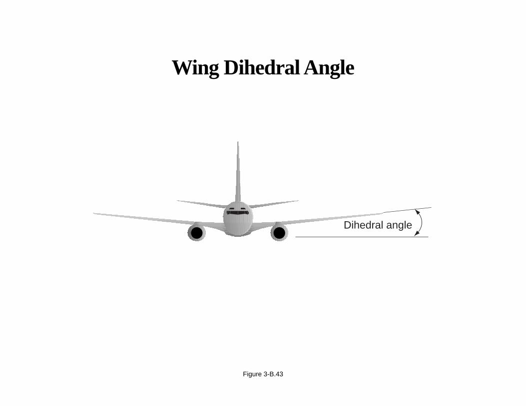
Wing Dihedral Effects
Dihedral is the positive angle formed between the lateral axis of an airplane and a line that passes through the center ofthe wing. A wing with dihedral will develop stable rolling moments with sideslip, and it contributes to the lateral stabilityof an airplane. The term “dihedral effect” is used when describing the effects of wing sweep and rudder on lateral stabilityand control. Wing sweep is beneficial for high-speed flight because it will delay compressibility effects. Wing sweepalso contributes to the dihedral effect. A sideslip on a swept-wing airplane results in a larger rolling moment than on astraight-wing airplane. Rudder input produces sideslip and contributes to the dihedral effect. The effect is proportionalto the angle of sideslip. At high angles of attack, aileron and spoiler roll controls become less effective. The rudder isstill effective; therefore, it can produce large sideslip angles, which in turn produces roll because of the dihedral effect.
Page 3-B.43
Wing Dihedral Angle
Figure 3-B.43
Dihedral angle
APPENDIX 3-B
Airplane Upset Recovery Briefing
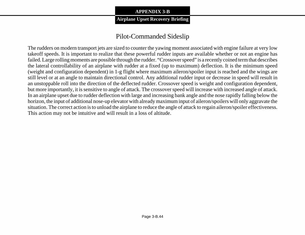
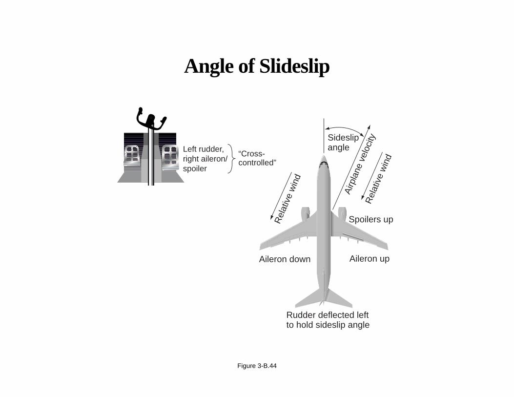
Pilot-Commanded Sideslip
The rudders on modern transport jets are sized to counter the yawing moment associated with engine failure at very lowtakeoff speeds. It is important to realize that these powerful rudder inputs are available whether or not an engine hasfailed. Large rolling moments are possible through the rudder. “Crossover speed” is a recently coined term that describesthe lateral controllability of an airplane with rudder at a fixed (up to maximum) deflection. It is the minimum speed(weight and configuration dependent) in 1-g flight where maximum aileron/spoiler input is reached and the wings arestill level or at an angle to maintain directional control. Any additional rudder input or decrease in speed will result inan unstoppable roll into the direction of the deflected rudder. Crossover speed is weight and configuration dependent,but more importantly, it is sensitive to angle of attack. The crossover speed will increase with increased angle of attack.In an airplane upset due to rudder deflection with large and increasing bank angle and the nose rapidly falling below thehorizon, the input of additional nose-up elevator with already maximum input of aileron/spoilers will only aggravate thesituation. The correct action is to unload the airplane to reduce the angle of attack to regain aileron/spoiler effectiveness.This action may not be intuitive and will result in a loss of altitude.
Page 3-B.44
Angle of Slideslip
Figure 3-B.44
Left rudder,right aileron/spoiler
“Cross-controlled”
Rudder deflected leftto hold sideslip angle
Aileron upAileron down
Spoilers up
Sideslipangle
Airp
lane
vel
ocity
Rel
ativ
e w
ind
Rel
ativ
e w
ind

APPENDIX 3-B
Airplane Upset Recovery Briefing
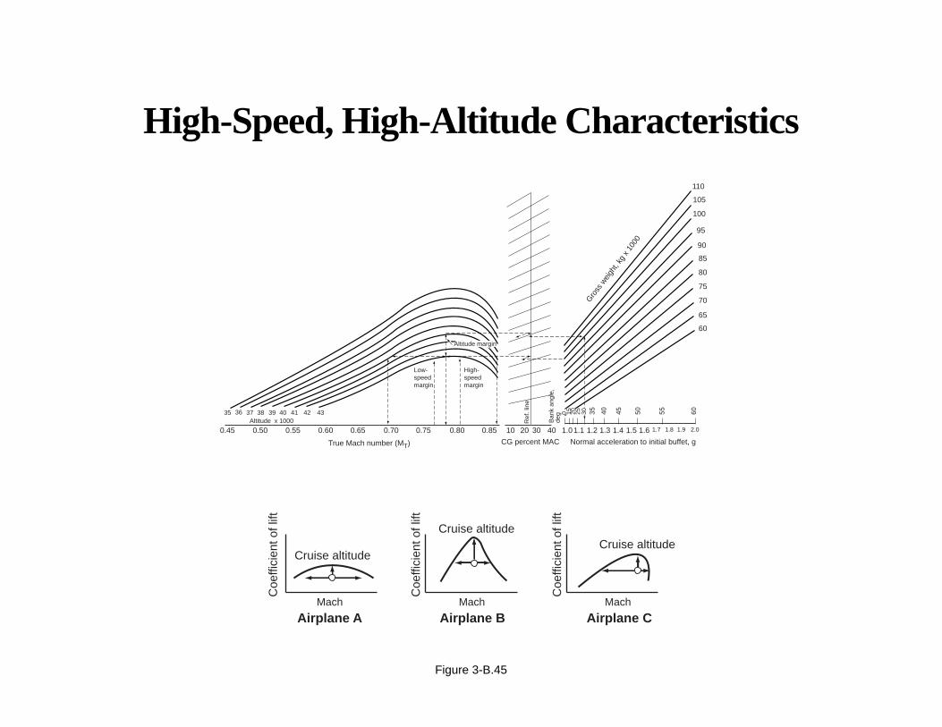
High-Speed, High-Altitude Characteristics
Aerodynamic characteristics of lifting surfaces are significantly affected by the ratio of airspeed to the speed of sound(expressed as Mach number). At high altitudes, large Mach numbers exist at relatively low calibrated airspeeds. As Machnumber increases, airflow over parts of the airplane begins to exceed the speed of sound. Shock waves, associated withthis local supersonic flow, can interfere with the normally smooth flow over the lifting surfaces. Depending on theairplane, characteristics such as pitchup, pitchdown, or aerodynamic buffeting may occur. The point at which buffetingwould be expected to occur is documented in the AFM. A sample chart is shown here. Some airplanes have broad speedmargins; some have abrupt high-speed buffet margins; and some have narrow, “peaky” characteristics, as depicted here.Pilots should become familiar with the buffet boundaries. These boundaries let the pilot know how much maneuveringroom is available.
• Airplane A has wide speed range but narrow g.
• Airplane B has narrow speed range but larger g.
• Airplane C has greater margin at slower speeds.
Page 3-B.45
High-Speed, High-Altitude Characteristics
Figure 3-B.45
0.45
35 36 37 38 39 40 41 42 43
0.50 0.55 0.60
60
65
70
75
80
85
90
95
100
105
110
0.65 0.70 0.75 0.80
High-speedmargin
Low-speedmargin
0.85 10 20 30 40 1.0 1.1 1.2 1.3 1.4 1.5 1.6 1.7 1.8 1.9 2.0
60555045403530252015
True Mach number (MT) CG percent MAC
Ref
. lin
e
Ban
k an
gle,
deg
Normal acceleration to initial buffet, g
Gro
ss w
eigh
t, kg
x 1
000
Altitude x 1000
0
Altitude margin
Mach
Airplane A Airplane B Airplane CMach Mach
Cruise altitude
Coe
ffici
ent o
f lift
Coe
ffici
ent o
f lift
Coe
ffici
ent o
f lift
Cruise altitudeCruise altitude
APPENDIX 3-B
Airplane Upset Recovery Briefing
Static Stability
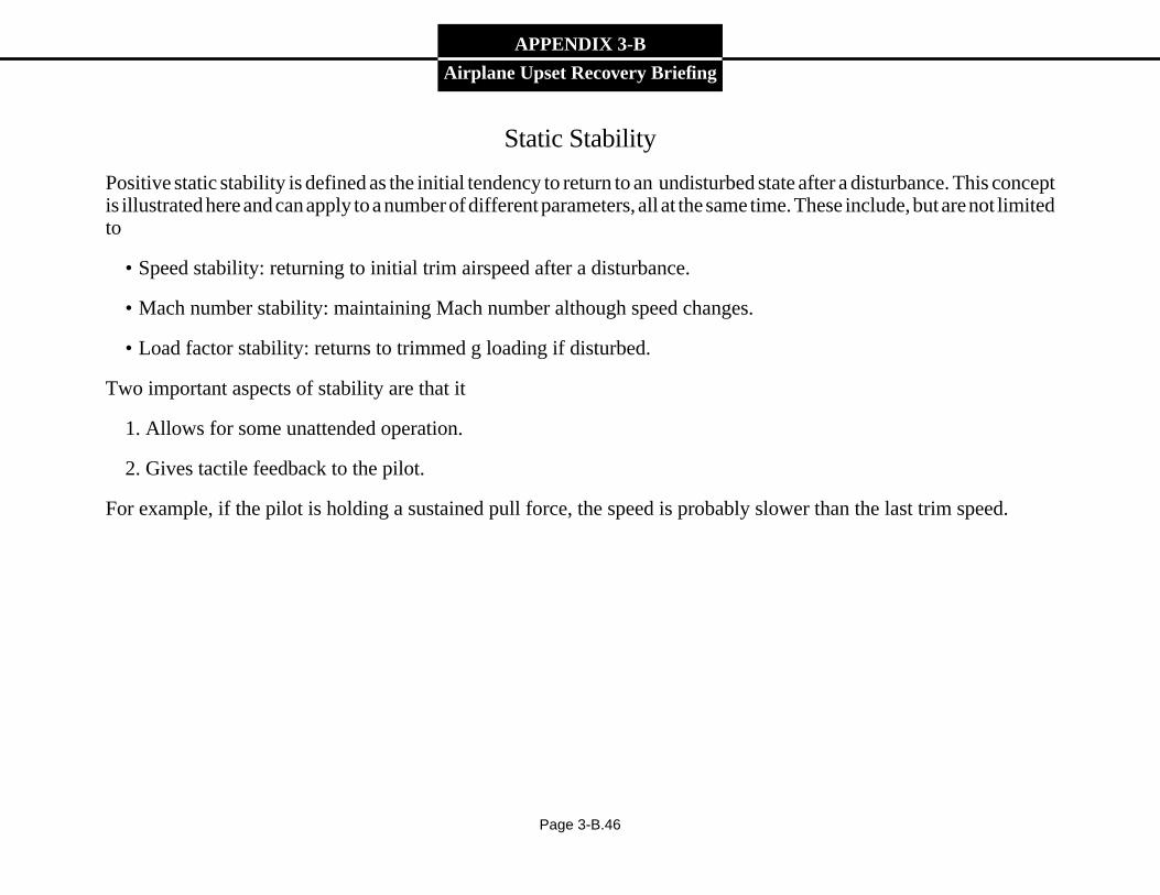
Positive static stability is defined as the initial tendency to return to an undisturbed state after a disturbance. This conceptis illustrated here and can apply to a number of different parameters, all at the same time. These include, but are not limitedto
• Speed stability: returning to initial trim airspeed after a disturbance.
• Mach number stability: maintaining Mach number although speed changes.
• Load factor stability: returns to trimmed g loading if disturbed.
Two important aspects of stability are that it
1. Allows for some unattended operation.
2. Gives tactile feedback to the pilot.
For example, if the pilot is holding a sustained pull force, the speed is probably slower than the last trim speed.
Page 3-B.46

Static Stability
Figure 3-B.46
Unstable NeutralStableWhen ball is displaced,it returns to its original position.
When ball is displaced,it accelerates from its original position.
When ball is displaced,it neither returns, nor accelerates away—itjust takes up a newposition.
APPENDIX 3-B
Airplane Upset Recovery Briefing
Page 3-B.47
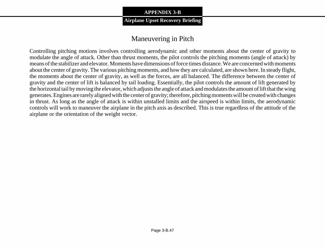
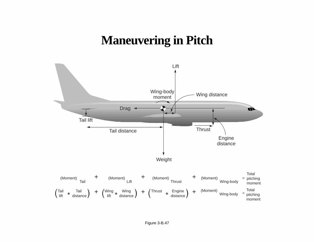
Maneuvering in Pitch
Controlling pitching motions involves controlling aerodynamic and other moments about the center of gravity tomodulate the angle of attack. Other than thrust moments, the pilot controls the pitching moments (angle of attack) bymeans of the stabilizer and elevator. Moments have dimensions of force times distance. We are concerned with momentsabout the center of gravity. The various pitching moments, and how they are calculated, are shown here. In steady flight,the moments about the center of gravity, as well as the forces, are all balanced. The difference between the center ofgravity and the center of lift is balanced by tail loading. Essentially, the pilot controls the amount of lift generated bythe horizontal tail by moving the elevator, which adjusts the angle of attack and modulates the amount of lift that the winggenerates. Engines are rarely aligned with the center of gravity; therefore, pitching moments will be created with changesin thrust. As long as the angle of attack is within unstalled limits and the airspeed is within limits, the aerodynamiccontrols will work to maneuver the airplane in the pitch axis as described. This is true regardless of the attitude of theairplane or the orientation of the weight vector.
Maneuvering in Pitch
Figure 3-B.47
Tail lift
Weight
Lift
Wing distance
Enginedistance
ThrustTail distance
Drag
Wing-bodymoment
(Moment)Tail
(Moment)Lift
(Moment)Thrust
(Moment) =Wing-body
(Moment)Wing-body
Totalpitchingmoment
=Totalpitchingmoment
+ + +
+Tail Tail + +* * *liftWing Wing
distancelift distanceThrust Engine
distance
APPENDIX 3-B
Airplane Upset Recovery Briefing
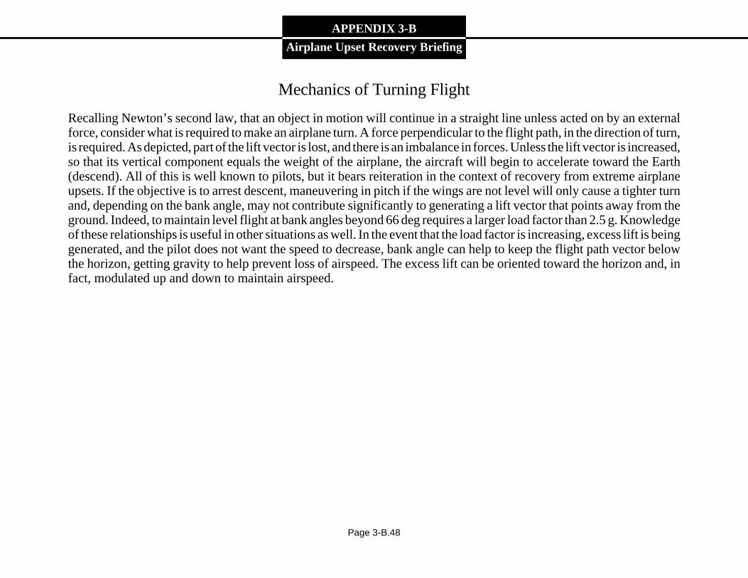
Mechanics of Turning Flight
Recalling Newton’s second law, that an object in motion will continue in a straight line unless acted on by an externalforce, consider what is required to make an airplane turn. A force perpendicular to the flight path, in the direction of turn,is required. As depicted, part of the lift vector is lost, and there is an imbalance in forces. Unless the lift vector is increased,so that its vertical component equals the weight of the airplane, the aircraft will begin to accelerate toward the Earth(descend). All of this is well known to pilots, but it bears reiteration in the context of recovery from extreme airplaneupsets. If the objective is to arrest descent, maneuvering in pitch if the wings are not level will only cause a tighter turnand, depending on the bank angle, may not contribute significantly to generating a lift vector that points away from theground. Indeed, to maintain level flight at bank angles beyond 66 deg requires a larger load factor than 2.5 g. Knowledgeof these relationships is useful in other situations as well. In the event that the load factor is increasing, excess lift is beinggenerated, and the pilot does not want the speed to decrease, bank angle can help to keep the flight path vector belowthe horizon, getting gravity to help prevent loss of airspeed. The excess lift can be oriented toward the horizon and, infact, modulated up and down to maintain airspeed.
Page 3-B.48

Mechanics of Turning Flight
Figure 3-B.48
Weight
Lift
Additionallift required so that vertical componentstill equals weight
Horizontal componentproduces curvedflight path = turn
4
3
2
1
3020100 5040 60 70
Loadfactor, g's
Bank angle, deg
APPENDIX 3-B
Airplane Upset Recovery Briefing
Lateral Maneuvering
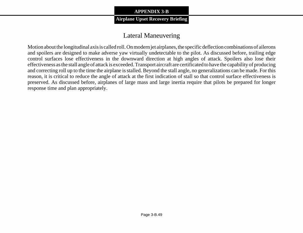
Motion about the longitudinal axis is called roll. On modern jet airplanes, the specific deflection combinations of aileronsand spoilers are designed to make adverse yaw virtually undetectable to the pilot. As discussed before, trailing edgecontrol surfaces lose effectiveness in the downward direction at high angles of attack. Spoilers also lose theireffectiveness as the stall angle of attack is exceeded. Transport aircraft are certificated to have the capability of producingand correcting roll up to the time the airplane is stalled. Beyond the stall angle, no generalizations can be made. For thisreason, it is critical to reduce the angle of attack at the first indication of stall so that control surface effectiveness ispreserved. As discussed before, airplanes of large mass and large inertia require that pilots be prepared for longerresponse time and plan appropriately.
Page 3-B.49

Lateral Maneuvering—Roll Axis
Figure 3-B.49
Lateral axis
Ver
tical
axi
s
Longitudinal
axis
Center ofgravity
Roll
APPENDIX 3-B
Airplane Upset Recovery Briefing
Lateral Maneuvering—Flight Dynamics
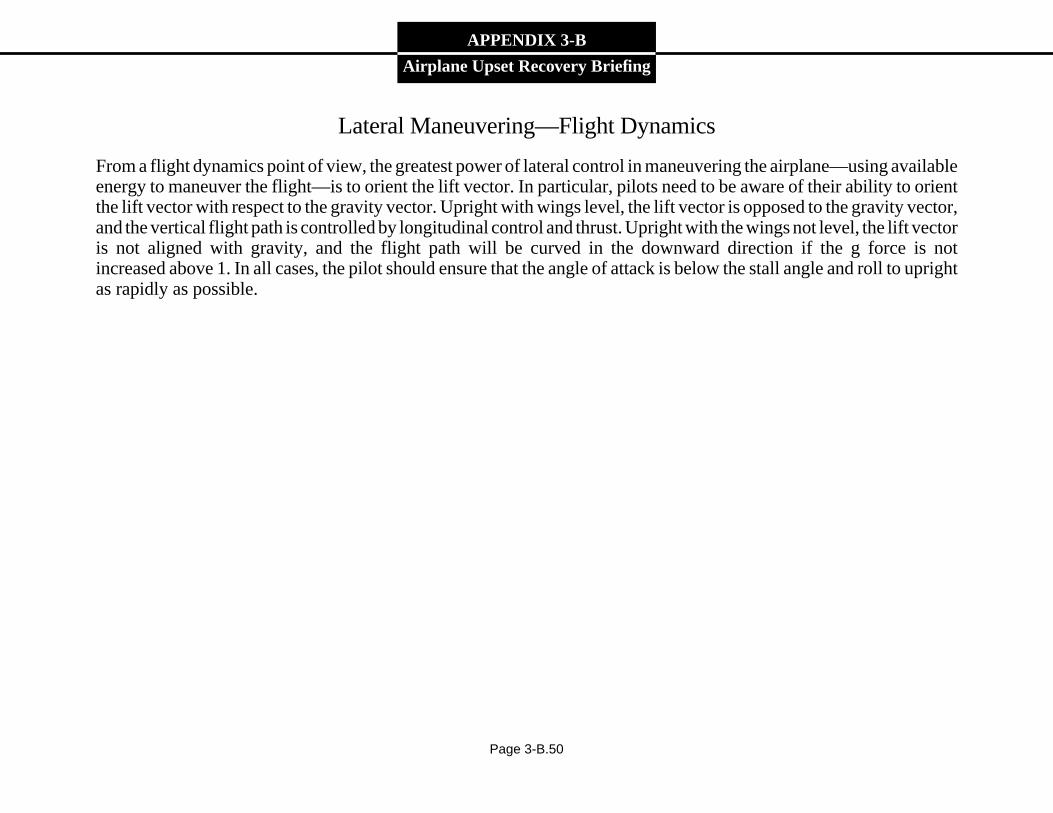
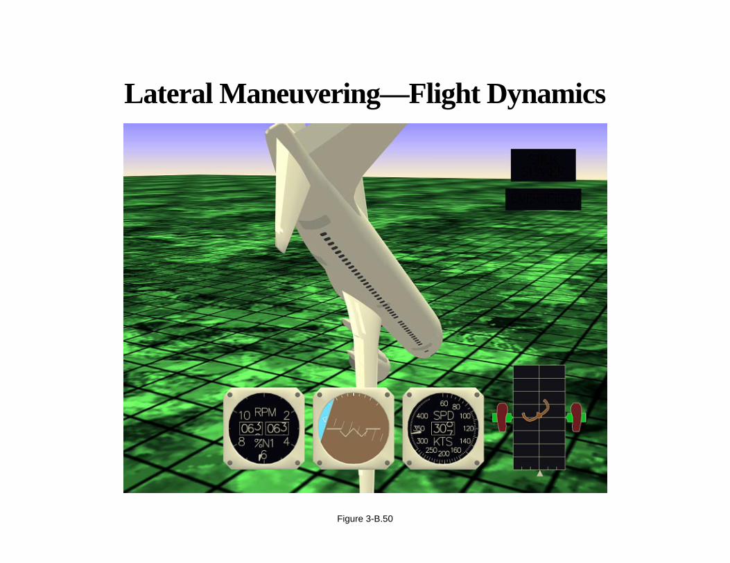
From a flight dynamics point of view, the greatest power of lateral control in maneuvering the airplane—using availableenergy to maneuver the flight—is to orient the lift vector. In particular, pilots need to be aware of their ability to orientthe lift vector with respect to the gravity vector. Upright with wings level, the lift vector is opposed to the gravity vector,and the vertical flight path is controlled by longitudinal control and thrust. Upright with the wings not level, the lift vectoris not aligned with gravity, and the flight path will be curved in the downward direction if the g force is notincreased above 1. In all cases, the pilot should ensure that the angle of attack is below the stall angle and roll to uprightas rapidly as possible.
Page 3-B.50
Lateral Maneuvering—Flight Dynamics
Figure 3-B.50
APPENDIX 3-B
Airplane Upset Recovery Briefing
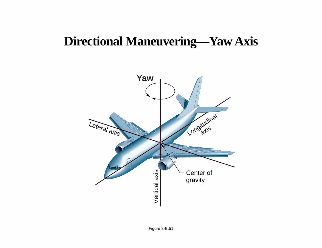
Directional Maneuvering
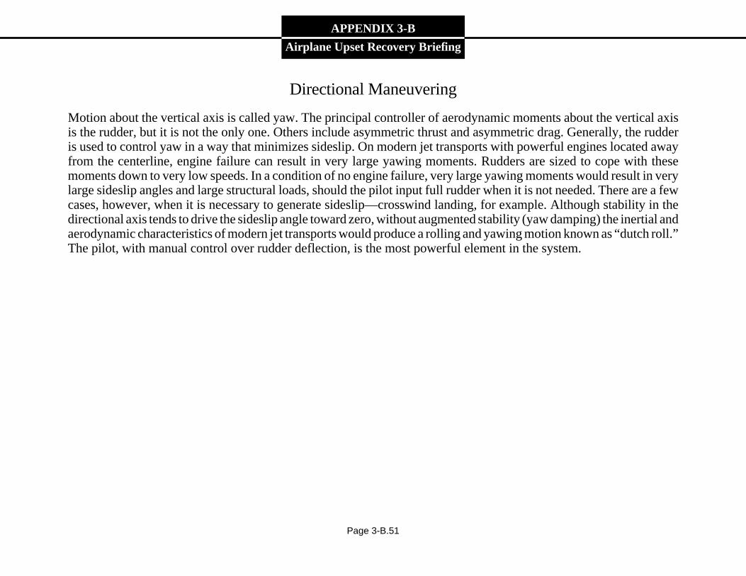
Motion about the vertical axis is called yaw. The principal controller of aerodynamic moments about the vertical axisis the rudder, but it is not the only one. Others include asymmetric thrust and asymmetric drag. Generally, the rudderis used to control yaw in a way that minimizes sideslip. On modern jet transports with powerful engines located awayfrom the centerline, engine failure can result in very large yawing moments. Rudders are sized to cope with thesemoments down to very low speeds. In a condition of no engine failure, very large yawing moments would result in verylarge sideslip angles and large structural loads, should the pilot input full rudder when it is not needed. There are a fewcases, however, when it is necessary to generate sideslip—crosswind landing, for example. Although stability in thedirectional axis tends to drive the sideslip angle toward zero, without augmented stability (yaw damping) the inertial andaerodynamic characteristics of modern jet transports would produce a rolling and yawing motion known as “dutch roll.”The pilot, with manual control over rudder deflection, is the most powerful element in the system.
Page 3-B.51
Directional Maneuvering—Yaw Axis
Figure 3-B.51
Lateral axis
Ver
tical
axi
s
Longitudinal
axis
Center ofgravity
Yaw
APPENDIX 3-B
Airplane Upset Recovery Briefing
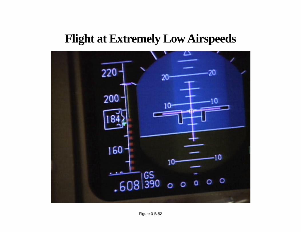
Flight at Extremely Low Airspeeds
It is possible for the airplane to be flown at speeds below the defined stall speed. This regime is outside the certified flightenvelope. At extremely low airspeed, there are several important effects for the pilot to know about. Lift generated bywings and tails depends on both the angle of attack and the velocity of the air moving over the surfaces. At very lowairspeeds, an unstalled surface will produce lift. The lift generated may not be enough to support the weight of theairplane. In the case of the lift generated by the tail, at very low airspeed, it may not be great enough to trim the airplane,that is, to keep it from pitching. The trajectory will be largely ballistic, and it may be difficult to command a change inattitude until gravity produces enough airspeed to generate sufficient lift—that is only possible at angles of attack belowthe stall angle. For this reason, if airspeed is decreasing rapidly, it is very important to reduce angle of attack and usewhatever aerodynamic forces are available to orient the airplane so that a recovery may be made when sufficient forces(airspeed) are available.
Page 3-B.52
Flight at Extremely Low Airspeeds
Figure 3-B.52
APPENDIX 3-B
Airplane Upset Recovery Briefing
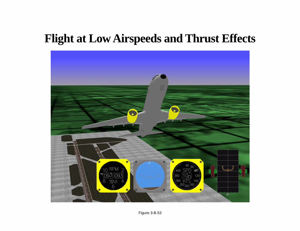
Flight at Extremely Low Airspeeds (continued)
The situation becomes only slightly more complicated when thrust is considered. With engines offset from the centerof gravity, thrust produces both forces and moments. As airspeed decreases, engine thrust generally increases for a giventhrottle setting. With engines below the center of gravity, there will be a nose-up moment generated by engine thrust.Especially at high power settings, this may contribute to even higher nose-up attitudes and even lower airspeeds.
Pilots should be aware that, as aerodynamic control effectiveness diminishes with lower airspeeds, the forces andmoments available from thrust become more evident, and until the aerodynamic control surfaces become effective, thetrajectory will depend largely on inertia and thrust effects.
Page 3-B.53
Flight at Low Airspeeds and Thrust Effects
Figure 3-B.53
APPENDIX 3-B
Airplane Upset Recovery Briefing
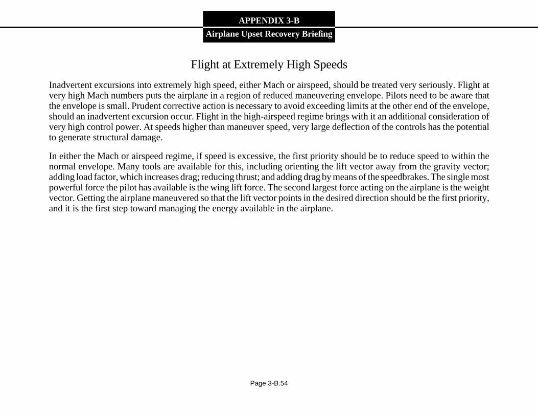
Flight at Extremely High Speeds
Inadvertent excursions into extremely high speed, either Mach or airspeed, should be treated very seriously. Flight atvery high Mach numbers puts the airplane in a region of reduced maneuvering envelope. Pilots need to be aware thatthe envelope is small. Prudent corrective action is necessary to avoid exceeding limits at the other end of the envelope,should an inadvertent excursion occur. Flight in the high-airspeed regime brings with it an additional consideration ofvery high control power. At speeds higher than maneuver speed, very large deflection of the controls has the potentialto generate structural damage.
In either the Mach or airspeed regime, if speed is excessive, the first priority should be to reduce speed to within thenormal envelope. Many tools are available for this, including orienting the lift vector away from the gravity vector;adding load factor, which increases drag; reducing thrust; and adding drag by means of the speedbrakes. The single mostpowerful force the pilot has available is the wing lift force. The second largest force acting on the airplane is the weightvector. Getting the airplane maneuvered so that the lift vector points in the desired direction should be the first priority,and it is the first step toward managing the energy available in the airplane.
Page 3-B.54
Flight at Extremely High Speeds
Figure 3-B.54
APPENDIX 3-B
Airplane Upset Recovery Briefing
Summary of Swept-Wing Fundamentals for Pilots
• Flight dynamics: Newton’s laws.
• Energy states: kinetic, potential, and chemical.
• Load factors: longitudinal, lateral, and vertical.
• Aerodynamic flight envelope: operating/demonstrated speeds.
• Aerodynamics: the relationship of angle of attack and stall.
Page 3-B.55
Summary of Swept-Wing Fundamentals
• Flight dynamics: Newton’s laws
• Energy states: kinetic, potential, and chemical
• Load factors: longitudinal, lateral, and vertical
• Aerodynamic flight envelope: operating anddemonstrated speeds
• Aerodynamics: the relationship of angle of attackand stall
Figure 3-B.55
APPENDIX 3-B
Airplane Upset Recovery Briefing
Recovery From Airplane Upsets
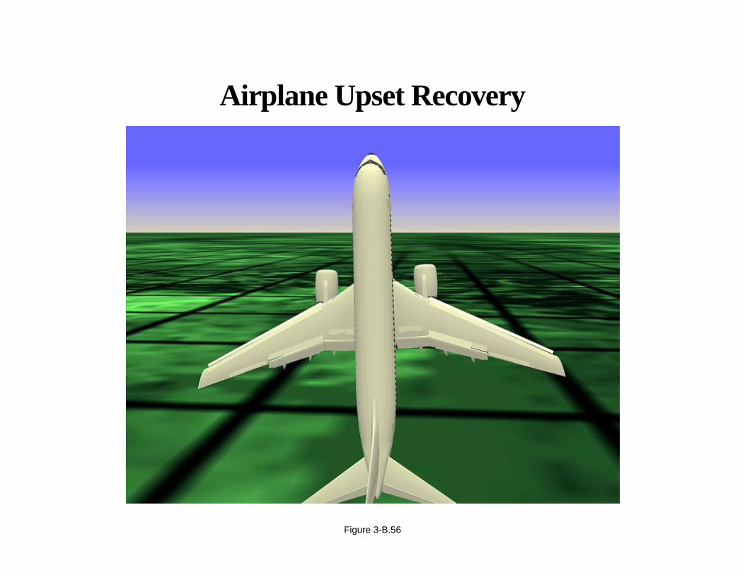
The first part of the briefing was devoted to the causes of airplane upsets. We had a brief review of how and why large,swept-wing airplanes fly. That information provides the foundation of knowledge necessary for recovering an airplanethat has been upset. This section highlights several issues associated with airplane upset recovery and presents basicrecommended airplane recovery techniques.
Page 3-B.56
Airplane Upset Recovery
Figure 3-B.56
APPENDIX 3-B
Airplane Upset Recovery Briefing
Situational Awareness During an Airplane Upset
It is important that the first actions be correct and timely. Guard against letting the recovery from one upset lead to adifferent upset situation. Troubleshooting the cause of the upset is secondary and can wait. Use the primary flightinstruments. Darkness, weather conditions, and the limited view from the cockpit will make it difficult to effectively usethe horizon. The Attitude Direction Indicator (ADI) is used as a primary reference.
Situation Analysis Process:
• Locate the Bank Indicator.
• Determine pitch attitude.
• Confirm attitude by reference to other indicators.
• Assess the energy state.
The phrase “Recognize and confirm the situation” will be used frequently in discussing recovery techniques. The processoutlined above is used to accomplish this.
Page 3-B.57
Situational Awareness During an Airplane Upset
“Recognize and confirm the situation” by thefollowing key steps:
• Locate the Bank Indicator
• Determine pitch attitude
• Confirm attitude by reference to other indicators
• Assess the energy state
Figure 3-B.57

APPENDIX 3-B
Airplane Upset Recovery Briefing
Miscellaneous Issues Associated With Upset Recovery
Pilots who have experienced an airplane upset have identified several issues associated with recovering from an upset.Observations of pilots in a simulator-training environment have also revealed useful information associated withrecovery.
Page 3-B.58
• Pilots who have experienced an airplane upset
• Pilot observations in a simulator-training environment
And they are associated with• The startle factor• Negative g force• Full control inputs• Counter-intuitive factors
The Miscellaneous Issues Associated With UpsetRecovery Have Been Identified by
Figure 3-B.58
APPENDIX 3-B
Airplane Upset Recovery Briefing
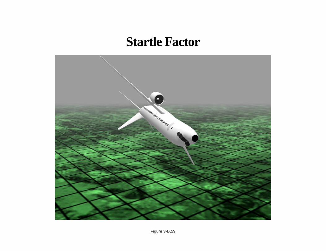
Startle Factor
Airplane upsets are infrequent; therefore, pilots are usually surprised or startled when an upset occurs. There is a tendencyto react before analyzing what is happening or to fixate on one indication and fail to properly diagnose the situation.
Page 3-B.59
Startle Factor
Figure 3-B.59
APPENDIX 3-B
Airplane Upset Recovery Briefing
Negative G Force
Airline pilots are normally uncomfortable (for the sake of passenger comfort and safety) with aggressively unloadingthe g forces on a large passenger airplane. This inhibition must be overcome when faced with the necessity to quicklyand sometimes aggressively unload the airplane to less than 1 g. Most simulators cannot replicate sustained negative gforces; therefore, the cockpit situation must be envisioned during less than 1-g flight. You may be floating up againstthe shoulder harness and seat belt. It may be difficult to reach the rudder pedals. Unsecured items may be flying aroundthe cockpit. It should be emphasized that it should not normally be necessary to obtain less than 0 g.
Page 3-B.60

�����������������������������������
����������������
��
������������������������������������������������
����������������������������������������������������
������������
������
������������������������
���������������
���������
���������������
��������
������������������������
������������
���������
������������
���������������������
������������������
����������������������������������������������
Negative G Force
Figure 3-B.60

APPENDIX 3-B
Airplane Upset Recovery Briefing
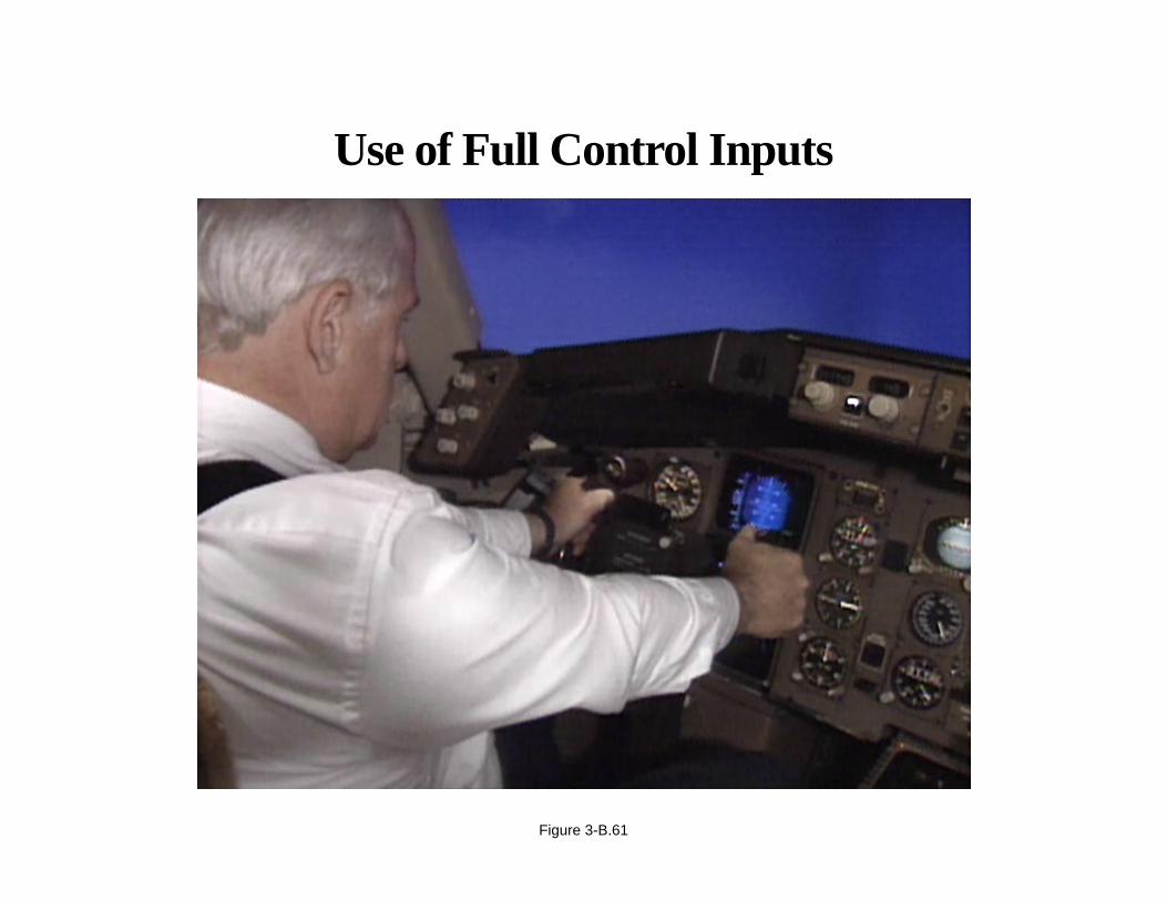
Use of Full Control Inputs
Flight control forces become less effective when the airplane is at or near its critical angle of attack or stall. The tendencyis for pilots not to use full control authority because they rarely are required to do so. This habit must be overcome whenrecovering from severe upsets.
Page 3-B.61
Use of Full Control Inputs
Figure 3-B.61

APPENDIX 3-B
Airplane Upset Recovery Briefing
Nonintuitive Factors
Pilots are routinely trained to recover from approach to stalls. The recovery routinely requires an increase in thrust anda relatively small reduction in pitch attitude. It may be counter-intuitive to use greater unloading control forces or toreduce thrust when recovering from a high angle of attack, especially at low altitudes. If the airplane is stalled whilealready in a nose-down attitude, the pilot must still push the nose down (unload) in order to reduce the angle of attack.Altitude cannot be maintained in a stall and should be of secondary importance.
Page 3-B.62

Nonintuitive Factors
Figure 3-B.62
APPENDIX 3-B
Airplane Upset Recovery Briefing
Airplane Upset Recovery Techniques
The following airplane upset situations will be discussed:
• Nose high, wings level.
• Nose low, wings level.
• High bank angles.
– Nose high.
– Nose low.
At the conclusion, recommended recovery techniques are summarized into two basic airplane upset situations:
• Nose high.
• Nose low.
Page 3-B.63
Airplane Upset Recovery Techniques Will Include aReview of the Following Airplane Upset Situations:
• Nose high, wings level
• Nose low, wings level
• High bank angles:– Nose high– Nose low
• And a review of recommended upset recoverytechniques based on two basic airplane upsetsituations:
– Nose high– Nose low
Figure 3-B.63
APPENDIX 3-B
Airplane Upset Recovery Briefing
Airplane Upset Recovery Techniques (continued)
Recovery techniques assume that the airplane is not stalled. If the airplane is stalled, it is imperative to first recover fromthe stalled condition before initiating the upset recovery technique. Do not confuse an approach to stall and a full stall.An approach to stall is controlled flight. An airplane that is stalled is out of control but can be recovered. A stall ischaracterized by any, or a combination of, the following:
• Buffeting, which could be heavy at times.
• A lack of pitch authority.
• A lack of roll control.
• Inability to arrest descent rate.
To recover from a stall, the angle of attack must be reduced below the stalling angle. Apply nose-down pitch control andmaintain it until stall recovery. Under certain conditions with underwing-mounted engines, it may be necessary to reducethrust to prevent the angle of attack from continuing to increase. Remember, in an upset situation, if the airplane is stalled,it is first necessary to recover from the stall before initiating upset recovery techniques.
Page 3-B.64
Airplane Upset Recovery Techniques
Figure 3-B.64
• Stall characteristics– Buffeting– Lack of pitch authority– Lack of roll control– Inability to arrest descent rate
APPENDIX 3-B
Airplane Upset Recovery Briefing
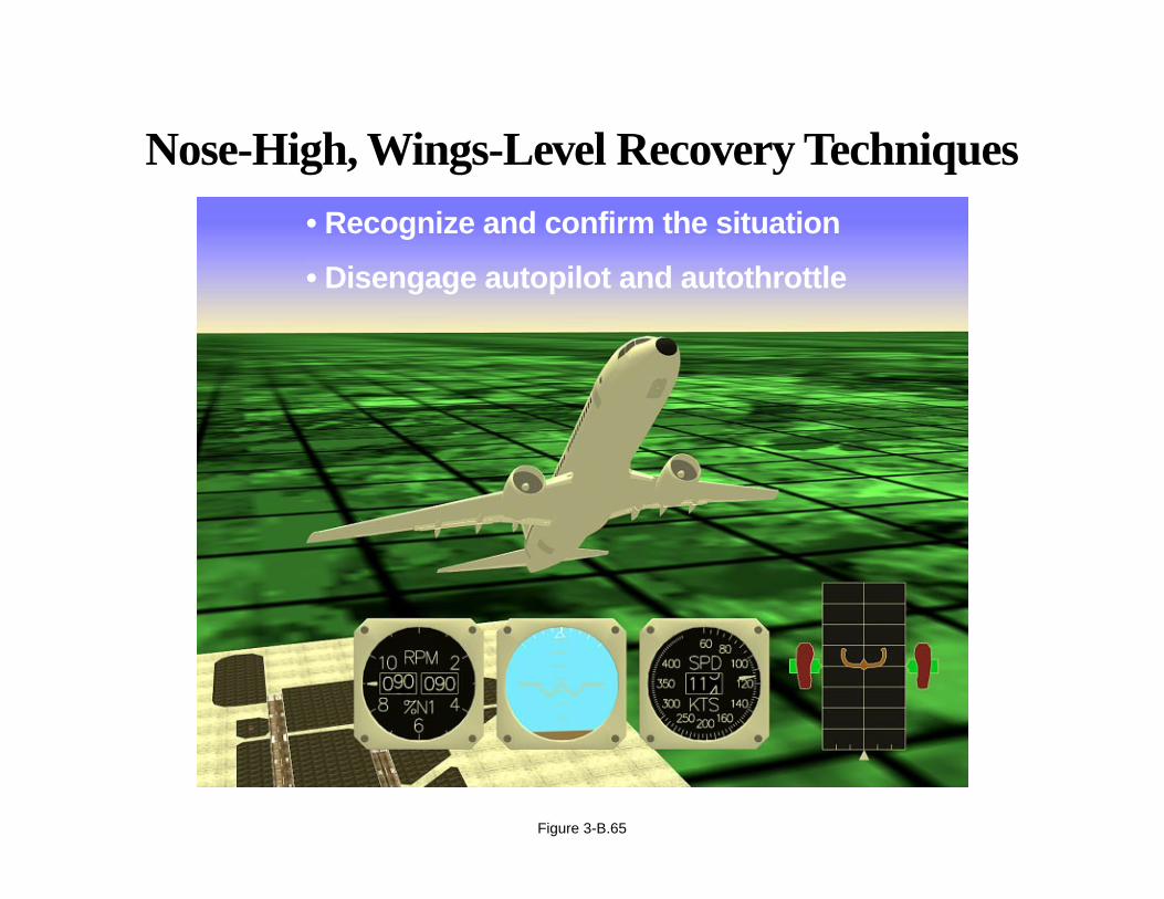
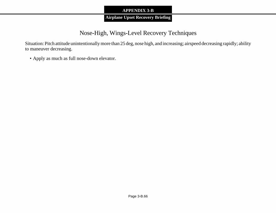
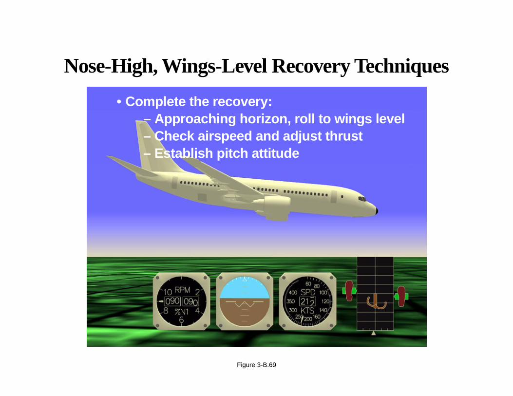
Nose-High, Wings-Level Recovery Techniques
Situation: Pitch attitude unintentionally more than 25 deg, nose high, and increasing; airspeed decreasing rapidly; abilityto maneuver decreasing.
• Recognize and confirm the situation.
• Disengage autopilot and autothrottle.
• Apply as much as full nose-down elevator.
• Use appropriate techniques:
– Roll to obtain a nose-down pitch rate.
– Reduce thrust (underwing-mounted engines).
• Complete the recovery:
– Approaching horizon, roll to wings level.
– Check airspeed and adjust thrust.
– Establish pitch attitude.
Page 3-B.65
Nose-High, Wings-Level Recovery Techniques
• Recognize and confirm the situation
• Disengage autopilot and autothrottle
Figure 3-B.65
APPENDIX 3-B
Airplane Upset Recovery Briefing
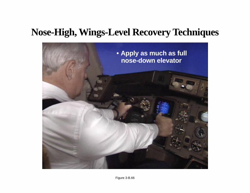
Nose-High, Wings-Level Recovery Techniques
Situation: Pitch attitude unintentionally more than 25 deg, nose high, and increasing; airspeed decreasing rapidly; abilityto maneuver decreasing.
• Apply as much as full nose-down elevator.
Page 3-B.66
Nose-High, Wings-Level Recovery Techniques
• Apply as much as fullnose-down elevator
Figure 3-B.66

APPENDIX 3-B
Airplane Upset Recovery Briefing
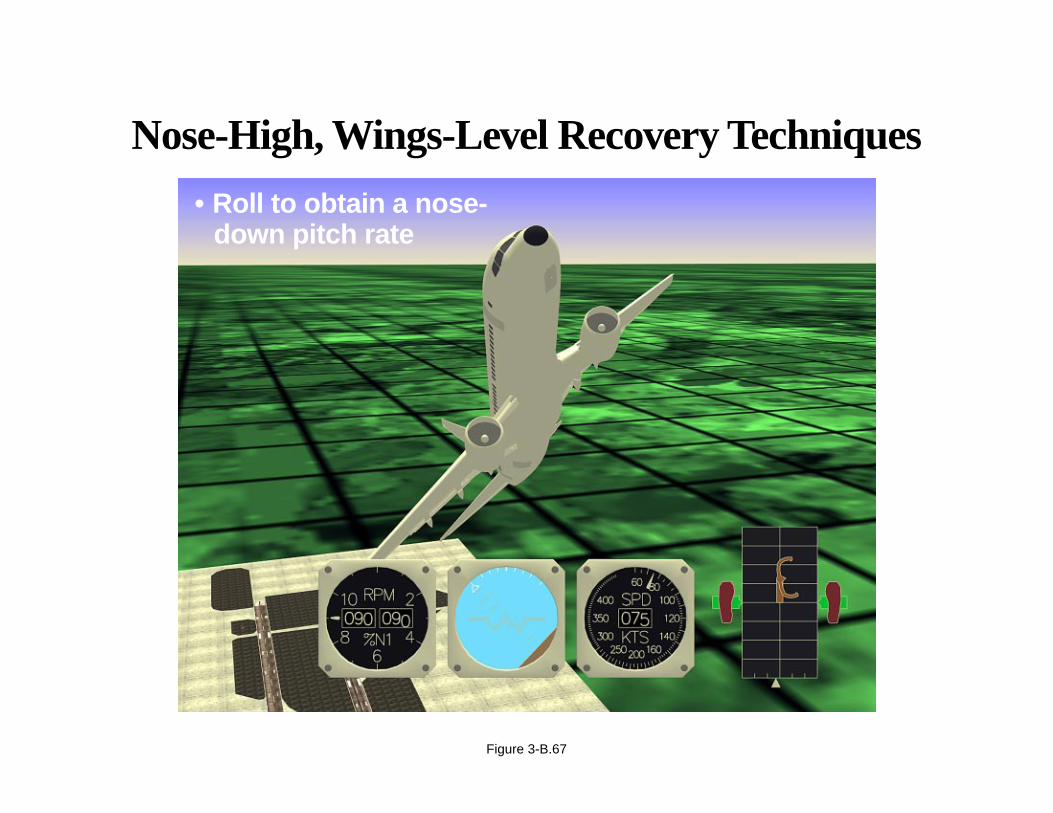
Nose-High, Wings-Level Recovery Techniques
Situation: Pitch attitude unintentionally more than 25 deg, nose high, and increasing; airspeed decreasing rapidly; abilityto maneuver decreasing.
• Use appropriate techniques:
– Roll to obtain a nose-down pitch rate.
Page 3-B.67
Nose-High, Wings-Level Recovery Techniques
• Roll to obtain a nose-down pitch rate
Figure 3-B.67

APPENDIX 3-B
Airplane Upset Recovery Briefing
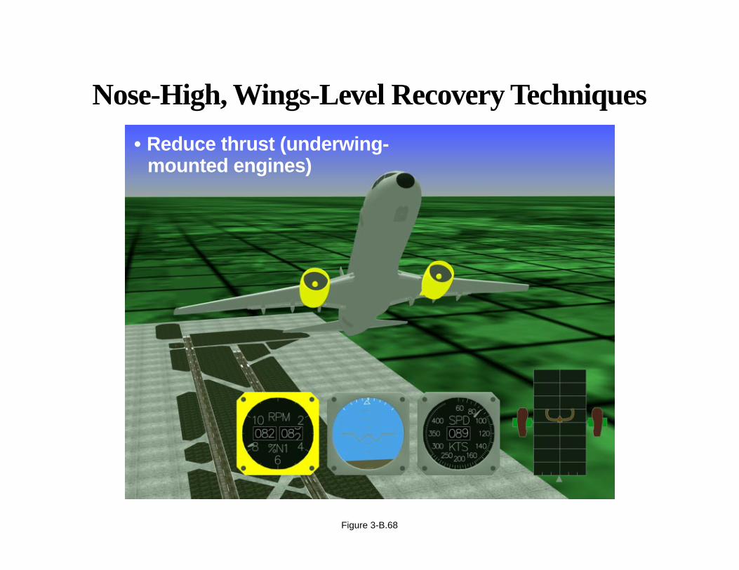
Nose-High, Wings-Level Recovery Techniques
Situation: Pitch attitude unintentionally more than 25 deg, nose high, and increasing; airspeed decreasing rapidly; abilityto maneuver decreasing.
• Use appropriate techniques: reduce thrust (underwing-mounted engines).
Page 3-B.68
Nose-High, Wings-Level Recovery Techniques
• Reduce thrust (underwing-mounted engines)
Figure 3-B.68

APPENDIX 3-B
Airplane Upset Recovery Briefing
Nose-High, Wings-Level Recovery Techniques
Situation: Pitch attitude unintentionally more than 25 deg, nose high, and increasing; airspeed decreasing rapidly; abilityto maneuver decreasing.
• Complete the recovery:
– Approaching horizon, roll to wings level.
– Check airspeed and adjust thrust.
– Establish pitch attitude.
Page 3-B.69
Nose-High, Wings-Level Recovery Techniques
• Complete the recovery:– Approaching horizon, roll to wings level– Check airspeed and adjust thrust– Establish pitch attitude
Figure 3-B.69
APPENDIX 3-B
Airplane Upset Recovery Briefing
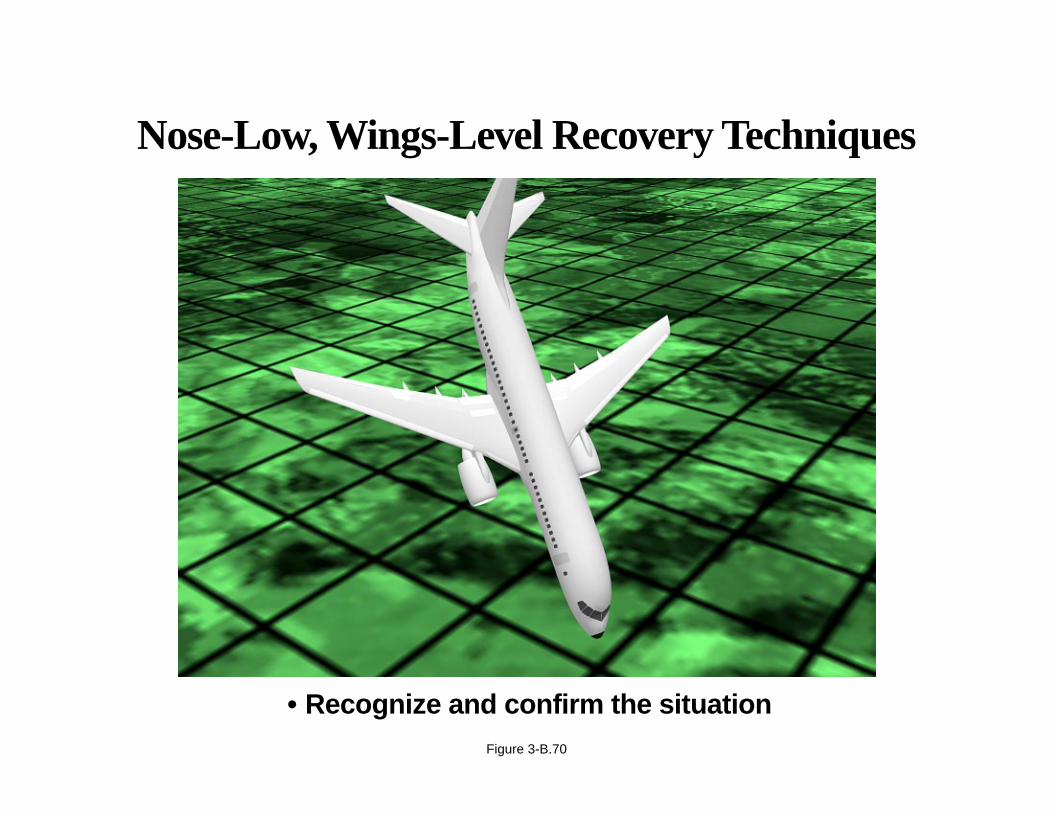
Nose-Low, Wings-Level Recovery Techniques
Situation: Pitch attitude unintentionally more than 10 deg, nose low.
• Recognize and confirm the situation.
• Disengage autopilot and autothrottle.
• Recover from stall, if necessary.
• Recover to level flight.
– Apply nose-up elevator.
– Apply stabilizer trim, if necessary.
– Adjust thrust and drag, as necessary.
Page 3-B.70
Nose-Low, Wings-Level Recovery Techniques
• Recognize and confirm the situationFigure 3-B.70

APPENDIX 3-B
Airplane Upset Recovery Briefing
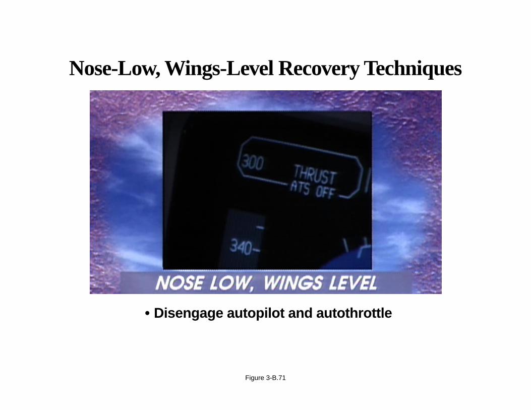
Nose-Low, Wings-Level Recovery Techniques
Situation: Pitch attitude unintentionally more than 10 deg, nose low.
• Disengage autopilot and autothrottle.
Page 3-B.71
Nose-Low, Wings-Level Recovery Techniques
• Disengage autopilot and autothrottle
Figure 3-B.71

APPENDIX 3-B
Airplane Upset Recovery Briefing
Nose-Low, Wings-Level Recovery Techniques
Situation: Pitch attitude unintentionally more than 10 deg, nose low.
• Recover from stall, if necessary.
Page 3-B.72
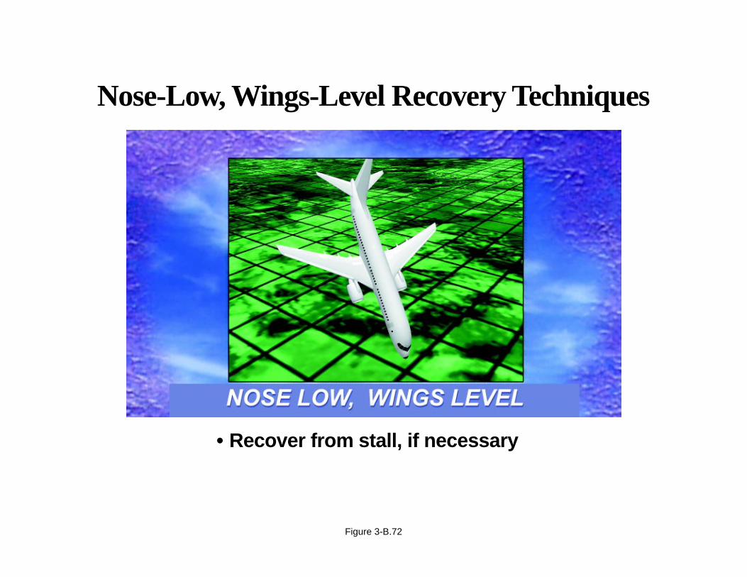
Nose-Low, Wings-Level Recovery Techniques
• Recover from stall, if necessary
Figure 3-B.72
APPENDIX 3-B
Airplane Upset Recovery Briefing
Nose-Low, Wings-Level Recovery Techniques
Situation: Pitch attitude unintentionally more than 10 deg, nose low.
• Recover to level flight:
– Apply nose-up elevator.
– Apply stabilizer trim, if necessary.
Page 3-B.73
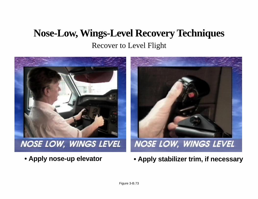
Nose-Low, Wings-Level Recovery TechniquesRecover to Level Flight
Figure 3-B.73
• Apply nose-up elevator • Apply stabilizer trim, if necessary
APPENDIX 3-B
Airplane Upset Recovery Briefing
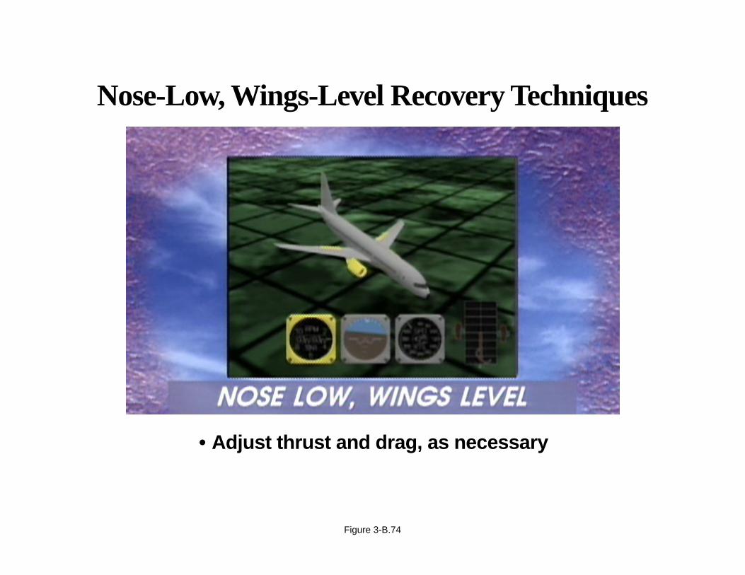
Nose-Low, Wings-Level Recovery Techniques
Situation: Pitch attitude unintentionally more than 10 deg, nose low.
• Adjust thrust and drag, as necessary.
Page 3-B.74
Nose-Low, Wings-Level Recovery Techniques
• Adjust thrust and drag, as necessary
Figure 3-B.74
APPENDIX 3-B
Airplane Upset Recovery Briefing
High-Bank-Angle Recovery Techniques
Situation: Bank angle greater than 45 deg; pitch attitude greater than 25 deg, nose high.
• Recognize and confirm the situation.
• Disengage autopilot and autothrottle.
• Reduce the angle of attack (unload).
• Adjust the bank angle to achieve a nose-down pitch rate.
• Complete the recovery:
– Approaching the horizon, roll to wings level.
– Check airspeed, adjust thrust.
– Establish pitch attitude.
Page 3-B.75
High-Bank-Angle Recovery Techniques
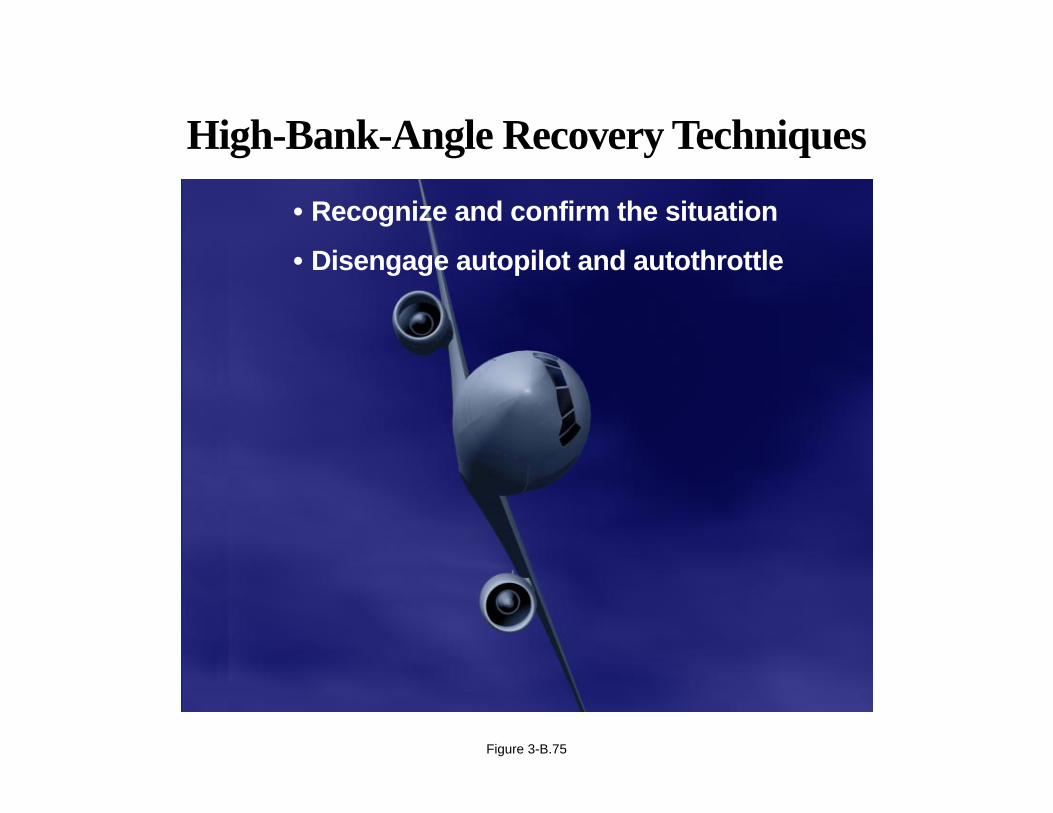
• Recognize and confirm the situation
• Disengage autopilot and autothrottle
Figure 3-B.75

APPENDIX 3-B
Airplane Upset Recovery Briefing
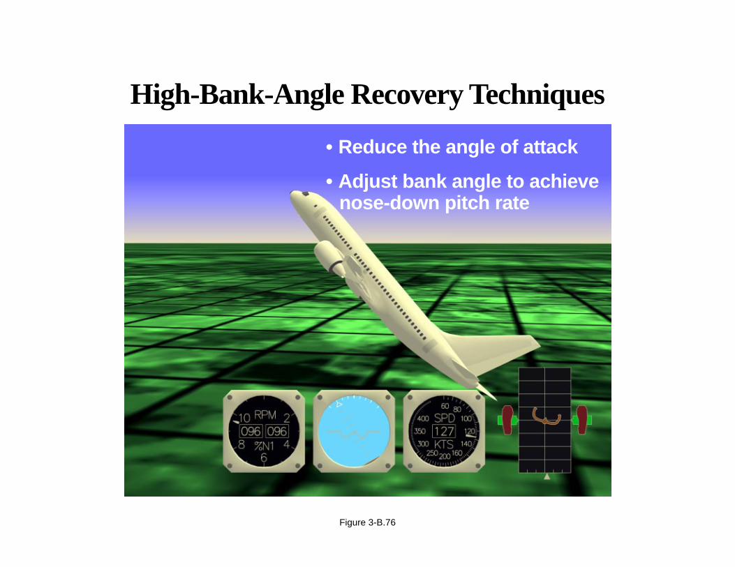
High-Bank-Angle Recovery Techniques
Situation: Bank angle greater than 45 deg; pitch attitude greater than 25 deg, nose high.
• Reduce the angle of attack.
• Adjust the bank angle to achieve a nose-down pitch rate.
Page 3-B.76
High-Bank-Angle Recovery Techniques
• Reduce the angle of attack
• Adjust bank angle to achievenose-down pitch rate
Figure 3-B.76

APPENDIX 3-B
Airplane Upset Recovery Briefing
High-Bank-Angle Recovery Techniques
Situation: Bank angle greater than 45 deg; pitch attitude greater than 25 deg, nose high.
• Complete the recovery:
– Approaching the horizon, roll to wings level.
– Check airspeed; adjust thrust.
– Establish pitch attitude.
Page 3-B.77
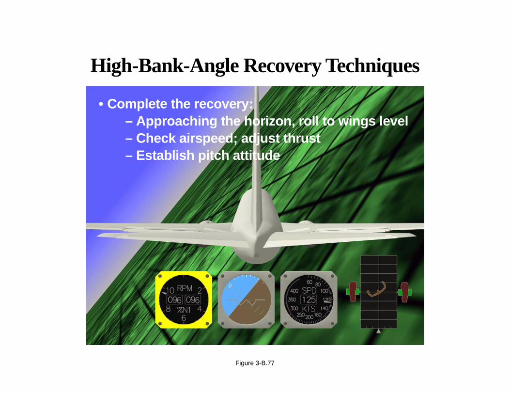
High-Bank-Angle Recovery Techniques
• Complete the recovery:– Approaching the horizon, roll to wings level– Check airspeed; adjust thrust– Establish pitch attitude
Figure 3-B.77
APPENDIX 3-B
Airplane Upset Recovery Briefing
High-Bank-Angle Recovery Techniques
Situation: Bank angle greater than 45 deg; pitch attitude lower than 10 deg; airspeed increasing.
• Recognize and confirm the situation.
• Disengage autopilot and autothrottle.
• Reduce the angle of attack, if necessary.
• Simultaneously reduce thrust and roll the shortest direction to wings level.
• Recover to level flight:
– Apply nose-up elevator.
– Apply stabilizer trim, if necessary.
– Adjust thrust and drag, as necessary.
Page 3-B.78
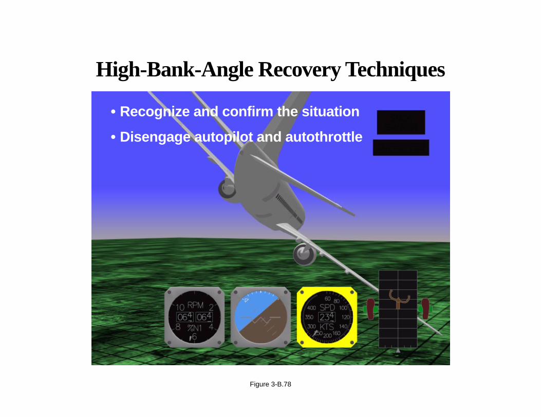
High-Bank-Angle Recovery Techniques
• Recognize and confirm the situation
• Disengage autopilot and autothrottle
Figure 3-B.78

APPENDIX 3-B
Airplane Upset Recovery Briefing
High-Bank-Angle Recovery Techniques
Situation: Bank angle greater than 45 deg; pitch attitude lower than 10 deg; airspeed increasing.
• Reduce the angle of attack, if necessary.
Page 3-B.79
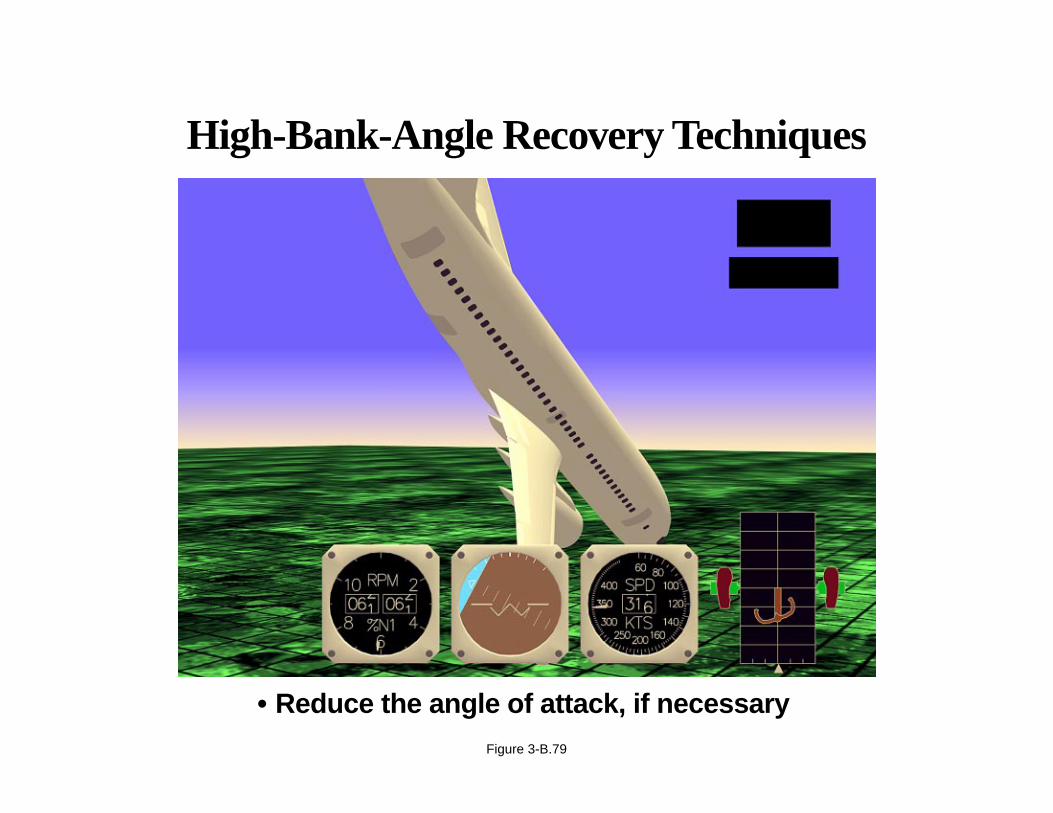
High-Bank-Angle Recovery Techniques
• Reduce the angle of attack, if necessaryFigure 3-B.79

APPENDIX 3-B
Airplane Upset Recovery Briefing
High-Bank-Angle Recovery Techniques
Situation: Bank angle greater than 45 deg; pitch attitude lower than 10 deg; airspeed increasing.
• Simultaneously reduce thrust and roll the shortest direction to wings level.
Page 3-B.80
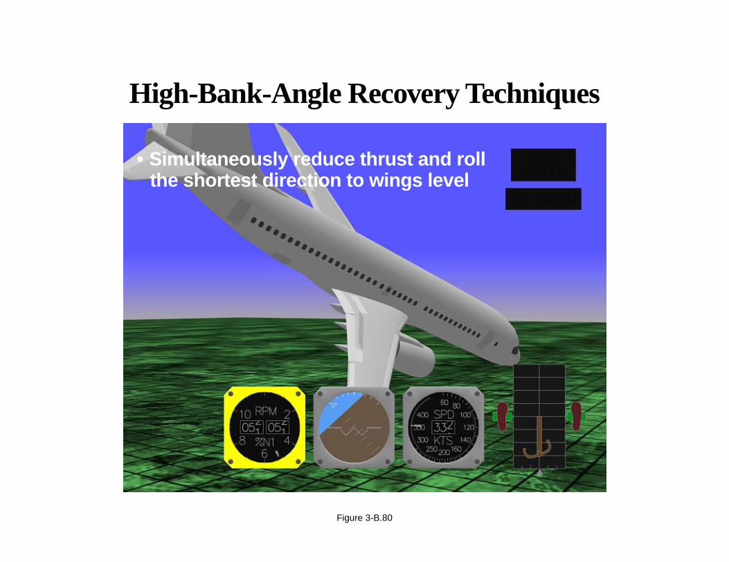
High-Bank-Angle Recovery Techniques
• Simultaneously reduce thrust and rollthe shortest direction to wings level
Figure 3-B.80

APPENDIX 3-B
Airplane Upset Recovery Briefing
High-Bank-Angle Recovery Techniques
Situation: Bank angle greater than 45 deg; pitch attitude lower than 10 deg; airspeed increasing.
• Recover to level flight:
– Apply nose-up elevator.
– Apply stabilizer trim, if necessary.
– Adjust thrust and drag, as necessary.
Page 3-B.81
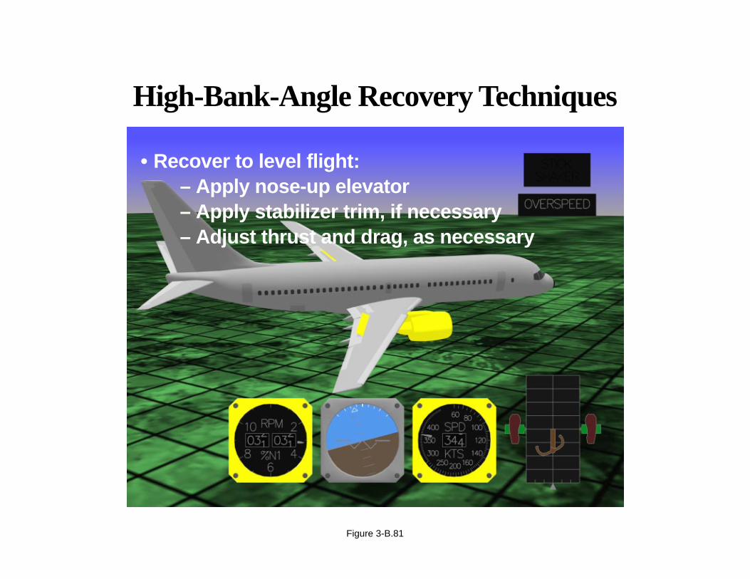
High-Bank-Angle Recovery Techniques
• Recover to level flight:– Apply nose-up elevator– Apply stabilizer trim, if necessary– Adjust thrust and drag, as necessary
Figure 3-B.81
APPENDIX 3-B
Airplane Upset Recovery Briefing
Consolidated Summary of Airplane Recovery Techniques
Nose-high recovery:
• Recognize and confirm the situation.
• Disengage autopilot and autothrottle.
• Apply as much as full nose-down elevator.
• Use appropriate techniques:
– Roll (adjust bank angle) to obtain a nose-down pitch rate.
– Reduce thrust (underwing-mounted engines).
• Complete the recovery:
– Approaching the horizon, roll to wings level.
– Check airspeed, adjust thrust.
– Establish pitch attitude.
Page 3-B.82

Summary of Airplane Recovery TechniquesNose-High Recovery
Figure 3-B.82

APPENDIX 3-B
Airplane Upset Recovery Briefing
Consolidated Summary of Airplane Recovery Techniques
Nose-high recovery:
• Recognize and confirm the situation.
• Disengage autopilot and autothrottle.
• Apply as much as full nose-down elevator.
Page 3-B.83
Summary of Airplane Recovery TechniquesNose-High Recovery
• Recognize and confirm the situation
• Disengage autopilot and autothrottle
• Apply as much as full nose-down elevator
Figure 3-B.83

APPENDIX 3-B
Airplane Upset Recovery Briefing
Consolidated Summary of Airplane Recovery Techniques
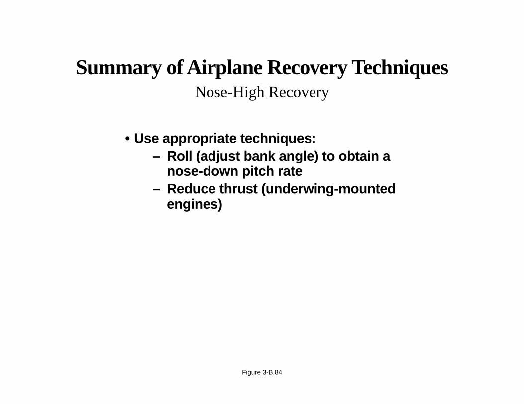
Nose-high recovery:
• Use appropriate techniques:
– Roll (adjust bank angle) to obtain a nose-down pitch rate.
– Reduce thrust (underwing-mounted engines).
Page 3-B.84
Summary of Airplane Recovery TechniquesNose-High Recovery
• Use appropriate techniques:– Roll (adjust bank angle) to obtain a
nose-down pitch rate– Reduce thrust (underwing-mounted
engines)
Figure 3-B.84
APPENDIX 3-B
Airplane Upset Recovery Briefing
Consolidated Summary of Airplane Recovery Techniques
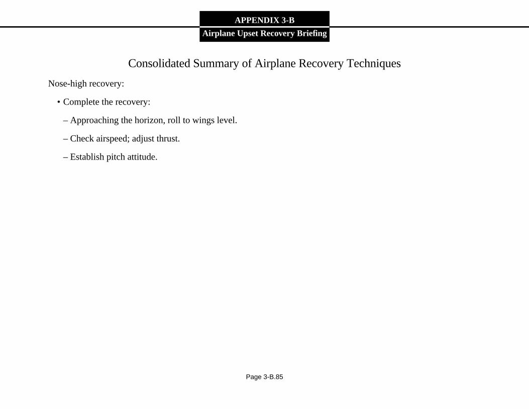
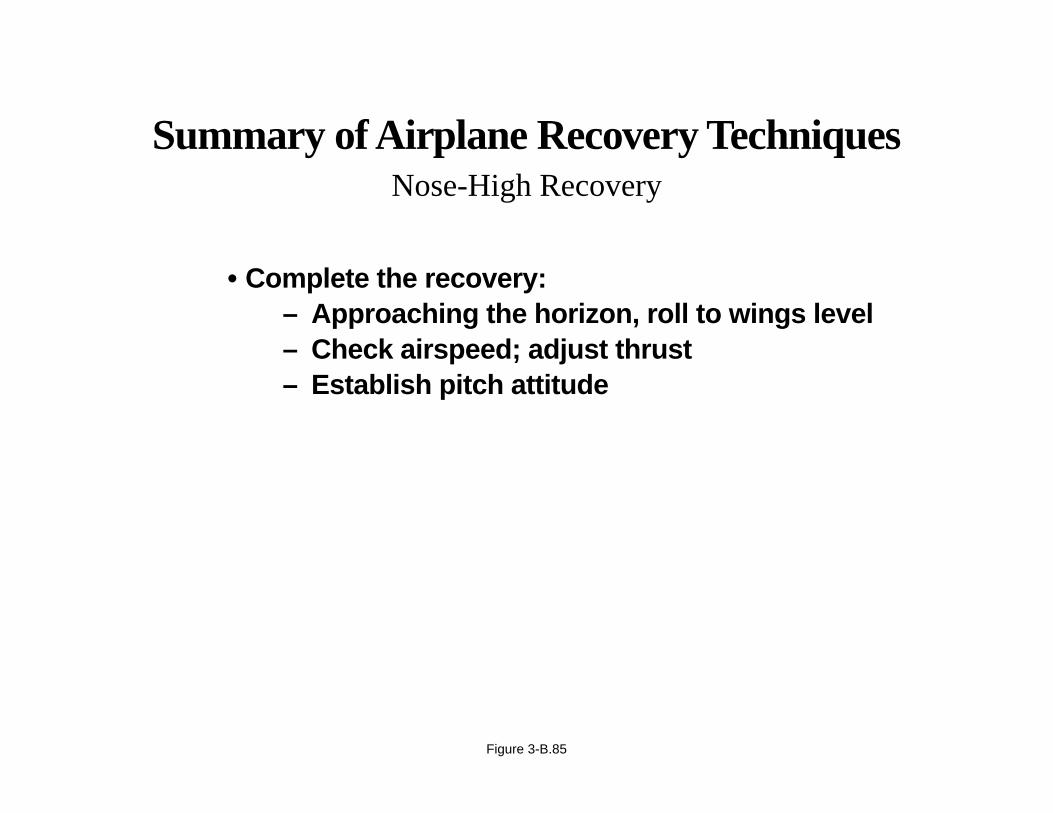
Nose-high recovery:
• Complete the recovery:
– Approaching the horizon, roll to wings level.
– Check airspeed; adjust thrust.
– Establish pitch attitude.
Page 3-B.85
Summary of Airplane Recovery TechniquesNose-High Recovery
• Complete the recovery:– Approaching the horizon, roll to wings level– Check airspeed; adjust thrust– Establish pitch attitude
Figure 3-B.85
APPENDIX 3-B
Airplane Upset Recovery Briefing
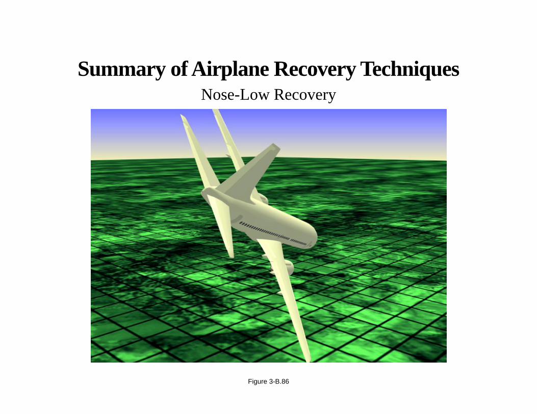
Consolidated Summary of Airplane Recovery Techniques
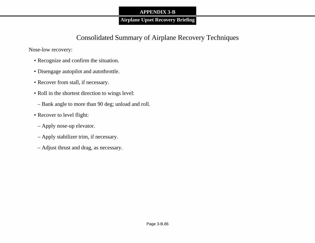
Nose-low recovery:
• Recognize and confirm the situation.
• Disengage autopilot and autothrottle.
• Recover from stall, if necessary.
• Roll in the shortest direction to wings level:
– Bank angle to more than 90 deg; unload and roll.
• Recover to level flight:
– Apply nose-up elevator.
– Apply stabilizer trim, if necessary.
– Adjust thrust and drag, as necessary.
Page 3-B.86
Summary of Airplane Recovery TechniquesNose-Low Recovery
Figure 3-B.86

APPENDIX 3-B
Airplane Upset Recovery Briefing
Consolidated Summary of Airplane Recovery Techniques
Nose-low recovery:
• Recognize and confirm the situation.
• Disengage autopilot and autothrottle.
• Recover from stall, if necessary.
Page 3-B.87
Summary of Airplane Recovery TechniquesNose-Low Recovery
• Recognize and confirm the situation
• Disengage autopilot and autothrottle
• Recover from stall, if necessary
Figure 3-B.87

APPENDIX 3-B
Airplane Upset Recovery Briefing
Consolidated Summary of Airplane Recovery Techniques
Nose-low recovery:
• Roll in the shortest direction to wings level:
– Bank angle to more than 90 deg; unload and roll.
Page 3-B.88
Summary of Airplane Recovery TechniquesNose-Low Recovery
• Roll in the shortest direction to wings level:– Bank angle to more than 90 deg;
unload and roll
Figure 3-B.88
APPENDIX 3-B
Airplane Upset Recovery Briefing
Consolidated Summary of Airplane Recovery Techniques
Nose-low recovery:
• Recover to level flight.
– Apply nose-up elevator.
– Apply stabilizer trim, if necessary.
– Adjust thrust and drag, as necessary.
Page 3-B.89
Summary of Airplane Recovery TechniquesNose-Low Recovery
• Recover to level flight– Apply nose-up elevator– Apply stabilizer trim, if necessary– Adjust thrust and drag, as necessary
Figure 3-B.89