Embed Size (px)
Citation preview

APPENDIX-3
Geological Survey Report

Submitted By:
Geological Survey for the Preparatory Survey on theProject for Construction of Mumbai Trans Harbour Link
AP3-1

IDEAL GEOSERVICES PRIVATE LIMITED
Geotechnical Investigation Report
THE PREPARATORY SURVEY ON THE PROJECT FOR
CONSTRUCTION OF
MUMBAI TRANS HARBOUR LINK, MUMBAI
For
6F, 3-12-1 Honmachi Shibuya-Ku,Tokyo
Japan
Submitted By
B-303, Hermes Atrium Plot No.57, Sector-11, CBD-Belapur
Navi Mumbai 400614 .Tel.: +91 22 65511401
E-mail: [email protected]
Project No. IDEAL-028-015
Document No. : IDEAL-028-015 Geoechnical Investigation Report_Rev 0
AP3-2

IDEAL-028-015 Geoechnical Investigation Report_Rev 0 i
IDEAL GEOSERVICES PRIVATE LIMITED
Project Information
Document Type : Geotechnical Investigation Report
Project : The Preparatory Survey on the Project For Construction of
Mumbai Trans Harbour link, Mumbai
Client : Oriental Consultants Global Co. Ltd
Project No. : IDEAL-028-015
Document No. : IDEAL-028-015 Geoechnical Investigation Report_Rev 0
Issued To: Oriental Consultants Global Co. Ltd
For the Attention of : Mr. Yoshiki Miyazaki / Mr. Y. Nozue Address : 6F, 3-12-1 Honmachi
Shibuya-Ku,Tokyo
Japan
6F, 3-12-1 Honmachi
Tel : +81 3 6311 7894 Fax : +81 3 6311 8044
Email : [email protected]
Issued By: Ideal Geoservices Pvt. Ltd
Dirrector : Mr. Sunil Pingle Address : Ideal Geoservices Pvt. Ltd B-303,Hermes Atrium,
Plot No 57, Sector-11, CBD Belapur, Navi Mumbai.
Tel : +91 22 65511401
Email : [email protected]
AP3-3

IDEAL-028-015 Geoechnical Investigation Report_Rev 0 ii
IDEAL GEOSERVICES PRIVATE LIMITED
Revision Control Revision
No. Description Prepared By
Checked By
ApprovedBy Issue Date
0
The Preparatory Survey on the Project For Construction of Mumbai Trans Harbour link, Mumbai
VN KB ST 18.08.2015
SQP Volume Description Volume
Title Volume Title Contents
N/A The Preparatory Survey on the Project For Construction of Mumbai Trans Harbour link, Mumbai
Results of Field and Laboratory Geotechnical Investigation
Service Warranty
The data presented within the report and associated charts/drawings have been acquired and processed to meet the requirements of the contract as agreed by the Oriental Consultants Global Co. Ltd. Any unauthorised use of the information presented within this report and charts/drawings is prohibited. Ideal Geoservices Pvt. Ltd. will not accept any liability if the data is used for purposes other than those agreed in the contract.
AP3-4

IDEAL-028-015 Geoechnical Investigation Report_Rev 0 iii
IDEAL GEOSERVICES PRIVATE LIMITED
Table of Contents Page
EXECUTIVE SUMMARY VI
1. INTRODUCTION 1 1.1. Reference Documentation 1 1.2. Scope of Work 1 1.3. Schedule of Activities 2
2. FIELD INVESTIGATION 2 2.1. Marine Spread 2 2.1.1. Jack Up barge Aqua Star 2 2.2. Position Services 2 2.3. Setting up at Field Test Location 3 2.4. Boring in Soil 4 2.5. Drilling in Rock 4 2.6. Standard Penetration Tests (SPT) 4 2.7. Undisturbed Soil Samples 4 2.8. Disturbed Soil Samples 4
3. LABORATORY TESTING 4 3.1. Laboratory Tests on Soil Samples 5 3.1.1. Moisture Content & Density 5 3.1.2. Particle Size Distribution 5 3.1.3. Sedimentation/ Hydrometer Analysis 6 3.1.4. Atterberg Limits 6 3.1.5. Particle Density/Specific Gravity 6 3.1.6. Consolidation Test 6 3.1.7. Unconfined Compressive Strength Test: 6 3.2. Laboratory Tests on Rock Samples 7 3.2.1. Unit Weight & Specific Gravity of Rock 7 3.2.2. Uniaxial Compressive Strength Test 7
List of Appendices Page
APPENDIX-A - ENGINEERING ILLUSTRATIONS 8
APPENDIX-B - SUMMARY OF LABORATORY TEST RESULTS 9
APPENDIX-C - CLASSIFICATION TEST RESULTS 10
APPENDIX-D - STRENGTH TEST RESULTS 11
APPENDIX-E - COMPRESSIBILITY TEST RESULTS 12
APPENDIX-F - CORE BOX PHOTOGRAPHS 13
AP3-5
IDEAL-028-015 Geoechnical Investigation Report_Rev 0 iv
IDEAL GEOSERVICES PRIVATE LIMITED
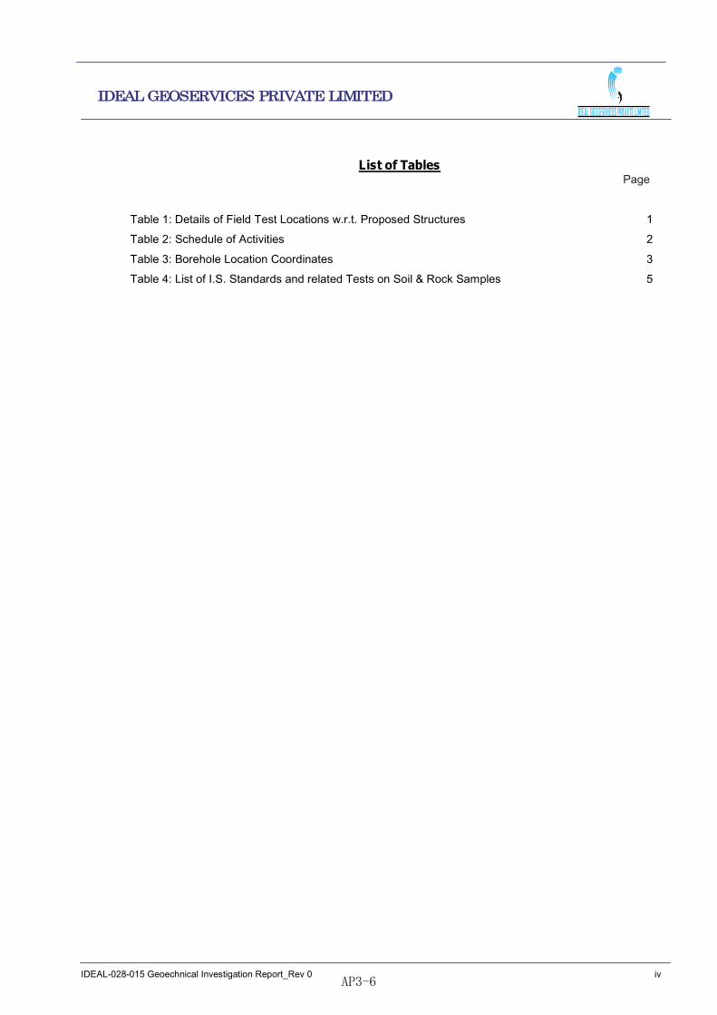
List of Tables
Page
Table 1: Details of Field Test Locations w.r.t. Proposed Structures 1 Table 2: Schedule of Activities 2 Table 3: Borehole Location Coordinates 3 Table 4: List of I.S. Standards and related Tests on Soil & Rock Samples 5
AP3-6

IDEAL-028-015 Geoechnical Investigation Report_Rev 0 v
IDEAL GEOSERVICES PRIVATE LIMITED
Abbreviations & Acronyms
The following list of abbreviations and acronyms may be present within the document: BARC Bhabha Atomic Research Centre
CD Chart Datum
dGPS Differential Global Positioning System
IGPL Ideal Geoservices Pvt Ltd
JNPT Jawaharlal Nehru Port Trust
JUB Jack Up Barge
MPT Mumbai Port Trust
SBL Sea Bed Level
SPT Standard Penetration Test
TD Termination Depth
UTM Universal Transverse Mercator
UCS Unconfined Compressive Strenght
WGS World Geodetic System
WRT With Respect To
Reference Colour Code The following reference colour coding may be used within this procedure: XXX Reference to an independent external document. XXX XXX
Reference to another section or article within this document. Important Note / Caution.
AP3-7

IDEAL-028-015 Geoechnical Investigation Report_Rev 0 vi
IDEAL GEOSERVICES PRIVATE LIMITED
EXECUTIVE SUMMARY
Site Location: MTHL Proposed Alignment
Investigation Date: Commenced from 3rd June 2015. Key observations: The sea bed level at the locations where the boreholes are carried out
varies from +0.9m CD to -5.60m CD. The sub sea bed stratigraphy encountered is heterogeneous along the
proposed alignment based on the boreholes drilled. The sub sea bed stratigraphy comprises of top Layer of very soft CLAY
in all boreholes except BH-04 and BH-06. In BH-04 and BH-06 the top layer comprises of SAND. The sub sea bed in general comprises of overburden followed by weak,
highly weathered BASALT underlain by moderatley strong, fresh BASALT.
In BH-03 and BH-06 the rock is encountered at relatively shallow level of -7.40m CD.
In BH04 even at levels below -29.0m CD the rock encountered is weak with UCS value between 5.47MPA to 8.59MPA.
The reason for this relatively low compressive strength is as given below
BH. No Elevation wrt
CD(m)
Reason for low
strength
Image
BH-04 -29.54 Because of secondary
infillings of the vugs.
Secondary infillings
are of minerals like
calcite, chlorite etc
BH-04 -30.80 Because weathering
extends through out
the rock. In some part
of the core the rock
material is friable
AP3-8

IDEAL-028-015 Geoechnical Investigation Report_Rev 0 1
IDEAL GEOSERVICES PRIVATE LIMITED
1. INTRODUCTION Oriental Consultants Global Co. Ltd (Client) contracted Ideal Geoservices Pvt. Ltd (Contractor) to
provide Geotechnical Investigation services for The Preparatory Survey on the Project For Construction of
Mumbai Trans Harbour link, Mumbai.
This report IDEAL-028-015 Geoechnical Investigation Report_Rev 0. presents the data obtained
from the field as well as laboratory investigation along the proposed alignment. The Geotechnical
Investigation field work was commenced on 3rd June 2015.
1.1. Reference Documentation
1. Service Agreement dated April 30, 2015.
2. Technical Specifications document no The Preparatory Survey on the Project for Construction of Mumbai Trans Harbor Link Terms of Reference .
1.2. Scope of Work
The principal objectives of the investigation were to obtain adequate information on the sub sea bed
stratigraphy, the type and strength of the soils / rocks below the seabed and other geotechnical details of
relevance to enable arriving at the design parameters for foundation of the proposed new structures and to
ascertain the compressibility of soil. The entire work was carried out under the supervision of Oriental Consultants Global Co. Ltd representatives.
In order to accomplish the above objectives the scope of work was to drill six (6) Nos. of boreholes upto a
depth of 35.0/50.0m below the sea bed or 5.0m into rock with RQD >50% which ever is shallower. The
scope of work also includes carrying out standard penetration tests, collection of disturbed and undisturbed
samples of soils, logging visually identifiable lithological and engineering characteristics of the soil and rock
samples, testing the samples in laboratory for their classification, index and engineering properties and
preparation and submission of Geotechnical Investigation report.
The list of the geotechnical boreholes carried out at locations of various proposed structures is presented
in Table-1.
Sr. No. Proposed Structure Boreholes
1 MTHL Bridge Alignment BH-01 thru BH-06
Table 1: Details of Field Test Locations w.r.t. Proposed Structures
AP3-9

IDEAL-028-015 Geoechnical Investigation Report_Rev 0 2
IDEAL GEOSERVICES PRIVATE LIMITED
1.3. Schedule of Activities
Investigation Schedule, MTHL, Mumbai
Sr. No.
Date Detail of Activities From To
01 01-05-2015 05-06-2015 Obtaining Permissions from Reliance, MPT,JNPT,BARC, Police, Ambuja cements
02 03-06-2015 10-06-2015 Standby at BH-06 location due to objection by Reliance
03 11-06-2015 10-07-2015 Carrying out 6 Boreholes
04 11-07-2015 17-08-2015 Laboratory Testing, preparation and submission of report
Note: The work was intermittently stopped due to inclement weather and unfavourable sea conditions on account of monsoon and cyclonic activities
Table 2: Schedule of Activities
2. FIELD INVESTIGATION
The field investigation involves mobilization of Marine Spread with drilling rigs and drilling accessories
mounted on it, marking the field test location and shifting the marine spread at the designated location,
boring in soil, drilling in rock, carry out SPT, collection of UDS. A brief description of the various activities is
given below.
2.1. Marine Spread
The marine spread comprises of JUB and two tug boats. The details of these are given below.
2.1.1. Jack Up barge Aqua Star
A hydraulically elevated JUB Aqua Star having deck size 12.0m x 10.0m with spuds of length 24.0m was
mobilized at the site. A Percussion boring rig along with a hydraulically operated rig supported with water
pumps was mounted on the deck. The JUB was assembled at Reti Bunder in Belapur and was towed to
the site and from one borehole to another using two Tug Boats named Dev Raj and Padma .
2.2. Position Services The coordinates of borehole locations were given by the client. The locations were identified at the site
using dGPS.
AP3-10

IDEAL-028-015 Geoechnical Investigation Report_Rev 0 3
IDEAL GEOSERVICES PRIVATE LIMITED
2.3. Setting up at Field Test Location
The location coordinates of the boreholes were supplied by the client. The borehole location was identified
in the field using dGSP. A Markey buoy was then dropped at the designated location from the advance
boat using dGPS.
The JUB was then towed to the location of the marker buoy using tug boats and was positioned at that
location by lowering the hydraulically operated spuds. After Jacking at the location the location coordinates
were again observed near the moonpool using the dGPS and these were then recorded as the actual
location coordinate of that field test and are presented in Table 3.
The list of proposed and actual coordinates of the borehole locations is given in Table-3.
Sr. No.
B.H. No
Proposed Actual Remarks
Easting (m)
Northing (m)
Easting (m)
Northing (m)
1 BH-01 276633.00 2101870.00 284389.00 2101122.00
Location shifted because
at the original location
even during high tide
water depth was not
sufficient to tow the JUB
2 BH-02 281893.00 2100979.00 281555.00 2100932.00
Location shifted on the
instruction of MPT as the
original location was
falling in the channel of
the Old Pir Pau Jetty.
3 BH-03 286953.00 2100893.00 286953.00 2100893.00
4 BH-04 287119.00 2100824.00 286846.00 2100932.00
Location shifted on the
instruction of Ambuja
Cement as the original
location was falling at the
centre of their channel
5 BH-05 287282.00 2100749.00 287282.00 2100749.00
6 BH-06 288918.00 2099540.00 288918.00 2099540.00
Table 3: Borehole Location Coordinates
AP3-11

IDEAL-028-015 Geoechnical Investigation Report_Rev 0 4
IDEAL GEOSERVICES PRIVATE LIMITED
2.4. Boring in Soil Boring was done in accordance with IS: 1892 -1979. A Standard boring winch of 1.5 ton was used for
boring in the overburden strata (soil strata) with 150mm dia boreholes. A standard boring winch consists of
a drum with rotating wheel where the wire rope was released and tight and one end is through pulley
mounted on the tripod. Other end of the wire rope was fixed with sinker bar and shell to bore in the soil.
Percussion method was used for boring in the overburden. The winch deployed was generally suitable for
all Geotechnical Investigation work and had an arrangement for driving and extraction of casing, boring
with percussion method. The boring was continued upto the termination of the borehole.
2.5. Drilling in Rock The borehole in rock was advanced using rotary drilling technique with the help of a hydraulic feed
machine. The coring was done using a NX size double tube core barrel giving a borehole of size 76.0mm
and core diameter of 54.5mm. The cores obtained were sequentially stored in the custom built core boxes.
2.6. Standard Penetration Tests (SPT)
non-return valve. The basis of the test consists of dropping a hammer of mass 63.5 kg (623N) on to a drive
head from a height of 750 mm (as specified in I.S. Code of Practice). An auto trip hammer capable of
dropping the weight freely on the anvil over a fixed height of 750mm was used to assure the quality of the
test. The number of such b
300mm (after its penetration under gravity and below the seating drive) is regarded as the penetration
resistance. The blow counts for each 150 mm penetration were recorded. Small disturbed samples were
obtained from the split spoon sampler after completion of the tests.
2.7. Undisturbed Soil Samples
Undisturbed Soil Samples were collected in cohesive soil using thin walled Shelby tubes having nominal
diameter of 100mm and minimum length of 450mm.
2.8. Disturbed Soil Samples
Disturbed soil samples were collected from the bailer of the percussion boring.
3. LABORATORY TESTING
Selected soil samples, collected during boring of the boreholes were subjected to laboratory tests to
determine the index and engineering characteristics as specified. The samples to be tested, type and
AP3-12

IDEAL-028-015 Geoechnical Investigation Report_Rev 0 5
IDEAL GEOSERVICES PRIVATE LIMITED
number of laboratory tests to be carried out were decided so as to derive the maximum relevant
information. Disturbed samples in SPT split spoons and undisturbed samples in thin walled tubes were
collected from the boreholes. The soil samples were visually identified and described in accordance with
relevant IS codes and thereafter packed, labelled, sealed and dispatched to the laboratory. The
classification, index property, NMC, specific gravity, density, chemical test, shear strength and
consolidation tests were carried out on the soil samples. All these tests were carried out in our laboratory
at Navi Mumbai, in accordance with relevant parts of Indian Standard Code of Practice. The list of IS and BS codes used is presented in Table 4 below. The summary of the laboratory test results is presented on
Appendix- B in plates B1 through B8. A brief discussion on the laboratory tests conducted is presented in
the following sections.
Test Designation Qty Applicable Standards Results Presented in
Tests on soil samples: Sieve Analysis 47 IS:2720 (PART -4) Plates C-1 thru C-16 Hydrometer Analysis 31 -DO- Do Atterberg Limit 27 IS:9259 (PART- 5) Plates C-17 to C-32 Specific Gravity 31 IS:2720 (PART-3 ) Plates B-1 thru B-6 Natural Moisture Content 2 IS:2720 (PART-2) Plates B-1 thru B-6 Bulk & Dry Density 2 IS:2720 ( PART-10) Plates B-1 thru B-6 Unconfined Compressive Strength Test 2 IS:2720 (PART-10) Plates D-1 to D-2
Consolidation Test 2 IS:2720 (PART-15) Plates E-1 thru E-2 Uniaxial Compressive Strength of R k
18 IS 9143 Plates B-7 thru B-8 Point load strength index test on
k3 IS 8764 Plates B-7 thru B-8
Porosity, unit weight and water b ti t t k l
21 IS 13013 Plates B-7 thru B-8
Table 4: List of I.S. Standards and related Tests on Soil & Rock Samples
The samples were tested and the test parameters were selected as per the contract and project
requirement. The following tests were performed:
3.1. Laboratory Tests on Soil Samples
3.1.1. Moisture Content & Density
Moisture content, bulk and dry densities were determined for a total of two (2) soil samples, in accordance
with the procedures of IS: 2720.
3.1.2. Particle Size Distribution
The particle size distribution was determined for a total of forty seven (47) soil samples in accordance with
the method described in IS:2720 (Part 4). Compliance with the Standard, with respect to minimum sample
quantity is dependent on the maximum sample available from the field test.
AP3-13
IDEAL-028-015 Geoechnical Investigation Report_Rev 0 6
IDEAL GEOSERVICES PRIVATE LIMITED
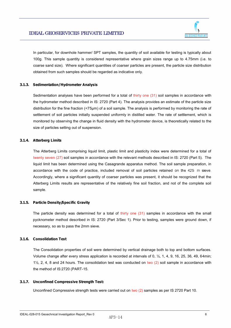
In particular, for downhole hammer/ SPT samples, the quantity of soil available for testing is typically about
100g. This sample quantity is considered representative where grain sizes range up to 4.75mm (i.e. to
coarse sand size). Where significant quantities of coarser particles are present, the particle size distribution
obtained from such samples should be regarded as indicative only.
3.1.3. Sedimentation/ Hydrometer Analysis
Sedimentation analyses have been performed for a total of thirty one (31) soil samples in accordance with
the hydrometer method described in IS: 2720 (Part 4). The analysis provides an estimate of the particle size
distribution for the fine fraction (<75µm) of a soil sample. The analysis is performed by monitoring the rate of
settlement of soil particles initially suspended uniformly in distilled water. The rate of settlement, which is
monitored by observing the change in fluid density with the hydrometer device, is theoretically related to the
size of particles setting out of suspension.
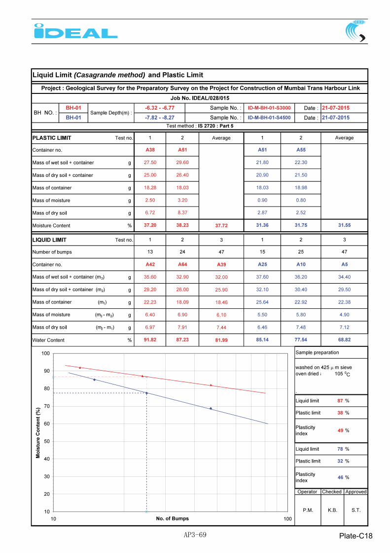
3.1.4. Atterberg Limits
The Atterberg Limits comprising liquid limit, plastic limit and plasticity index were determined for a total of
twenty seven (27) soil samples in accordance with the relevant methods described in IS: 2720 (Part 5). The
liquid limit has been determined using the Casagrande apparatus method. The soil sample preparation, in
accordance with the code of practice, included removal of soil particles retained
Accordingly, where a significant quantity of coarser particles was present, it should be recognized that the
Atterberg Limits results are representative of the relatively fine soil fraction, and not of the complete soil
sample.
3.1.5. Particle Density/Specific Gravity
The particle density was determined for a total of thirty one (31) samples in accordance with the small
pycknometer method described in IS: 2720 (Part 3/Sec 1). Prior to testing, samples were ground down, if
necessary, so as to pass the 2mm sieve.
3.1.6. Consolidation Test
The Consolidation properties of soil were determined by vertical drainage both to top and bottom surfaces.
Volume change after every stress application is recorded at intervals of 0, ½, 1, 4, 9, 16, 25, 36, 49, 64min;
1½, 2, 4, 8 and 24 hours. The consolidation test was conducted on two (2) soil sample in accordance with
the method of IS:2720 (PART-15.
3.1.7. Unconfined Compressive Strength Test: Unconfined Compressive strength tests were carried out on two (2) samples as per IS 2720 Part 10.
AP3-14

IDEAL-028-015 Geoechnical Investigation Report_Rev 0 7
IDEAL GEOSERVICES PRIVATE LIMITED
3.2. Laboratory Tests on Rock Samples
3.2.1. Unit Weight & Specific Gravity of Rock
Unit Weight & Specific Gravity of Rock specimen were determined for a total of twenty one (21) rock
samples by using saturation and buoyancy technique, in accordance with the methods of IS: 13030.
3.2.2. Uniaxial Compressive Strength Test
Uniaxial compressive strength for a total of eighteen (18) cylindrical rock specimens was determined, in
accordance with the methods of ISRM. The uniaxial compressive strength of the specimens were corrected
for a height to diameter ratio of two for specimens whose height to diameter ratio was other than two using
the following relationship
qc (corrected) = (qc 0.889)/(0.778+(0.222D/H))
Where qc = Uncorrected Uniaxial Compressive Strength
D = Diameter of the specimen tested
AP3-15

IDEAL-028-015 Geoechnical Investigation Report_Rev 0 8
IDEAL GEOSERVICES PRIVATE LIMITED
APPENDIX-A - ENGINEERING ILLUSTRATIONS
AP3-16

Geological Survey for the Preparatory Survey on the Project for Construction of MumbaiTrans Harbour Link
BOREHOLE LOCATION
AP3-17

Plate-A1
AP3-18
Plate-A2
AP3-19

Plate-A3
AP3-20

Plate-A4
AP3-21

Plate-A5
AP3-22

Plate-A6
AP3-23
Plate-A7
AP3-24

Plate-A8
AP3-25

Plate-A9
AP3-26

Plate-A10
AP3-27

Plate-A11
AP3-28
Plate-A12
AP3-29

Plate-A13
AP3-30

Plate-A14
AP3-31

Plate-A15
AP3-32

Plate-A16
AP3-33

Plate-A17
AP3-34

Plate-A18
AP3-35

AP3-36

AP3-37

AP3-38

AP3-39

AP3-40

AP3-41

IDEAL-028-015 Geoechnical Investigation Report_Rev 0 9
IDEAL GEOSERVICES PRIVATE LIMITED
APPENDIX-B - SUMMARY OF LABORATORY TEST RESULTS
AP3-42

SUMMARY OF LABORATORY TEST RESULTS ON SOIL SAMPLES
Plate-B1
AP3-43
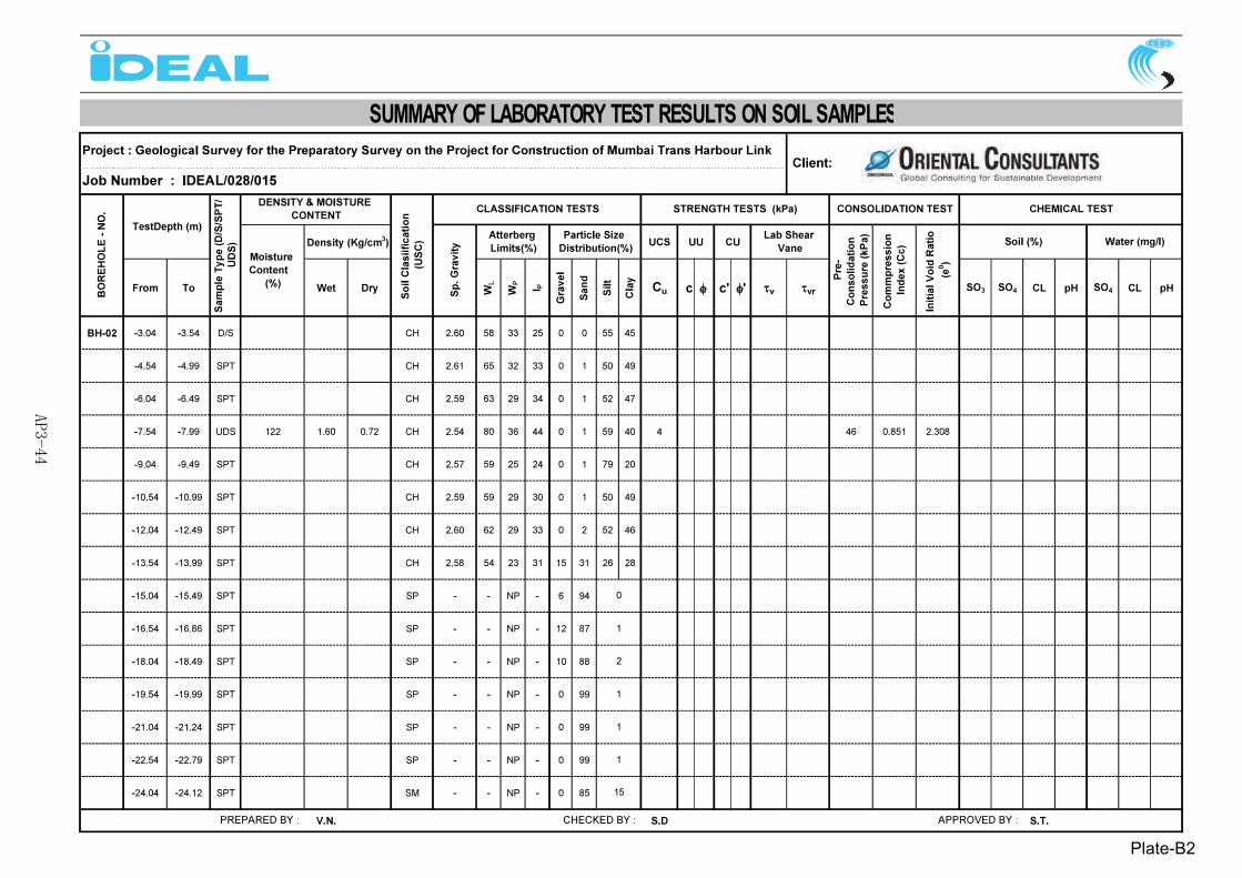
SUMMARY OF LABORATORY TEST RESULTS ON SOIL SAMPLES
Plate-B2
AP3-44

SUMMARY OF LABORATORY TEST RESULTS ON SOIL SAMPLES
Plate-B3
AP3-45

SUMMARY OF LABORATORY TEST RESULTS ON SOIL SAMPLES
Plate-B4
AP3-46

SUMMARY OF LABORATORY TEST RESULTS ON SOIL SAMPLES
Plate-B5
AP3-47

SUMMARY OF LABORATORY TEST RESULTS ON SOIL SAMPLES
Plate-B6
AP3-48
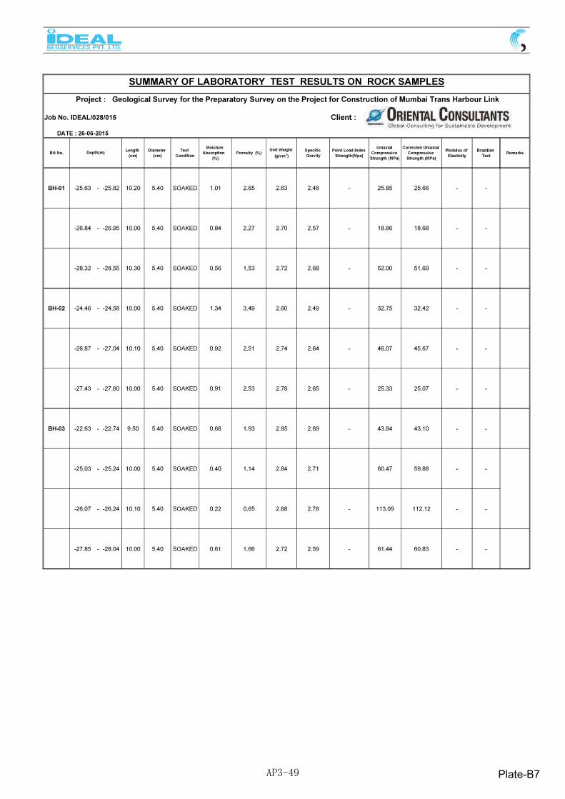
Plate-B7AP3-49

Plate-B8AP3-50

IDEAL-028-015 Geoechnical Investigation Report_Rev 0 10
IDEAL GEOSERVICES PRIVATE LIMITED
APPENDIX-C - CLASSIFICATION TEST RESULTS
AP3-51

Plate-C1AP3-52

Plate-C2AP3-53

Plate-C3AP3-54

Plate-C4AP3-55

Plate-C5AP3-56

Plate-C6AP3-57
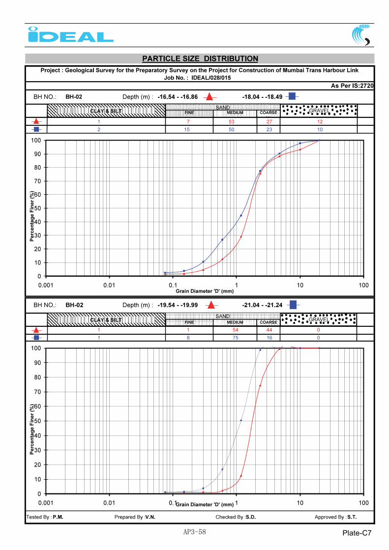
Plate-C7AP3-58

Plate-C8AP3-59
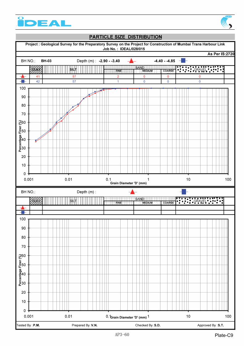
Plate-C9AP3-60

Plate-C10AP3-61

Plate-C11AP3-62

Plate-C12AP3-63

Plate-C13AP3-64

Plate-C14AP3-65

Plate-C15AP3-66

Plate-C16AP3-67

(Casagrande method)
Plate-C17AP3-68
(Casagrande method)
Plate-C18AP3-69

(Casagrande method)
Plate-C19AP3-70

(Casagrande method)
Plate-C20AP3-71

(Casagrande method)
Plate-C21AP3-72

(Casagrande method)
Plate-C22AP3-73

(Casagrande method)
Plate-C23AP3-74
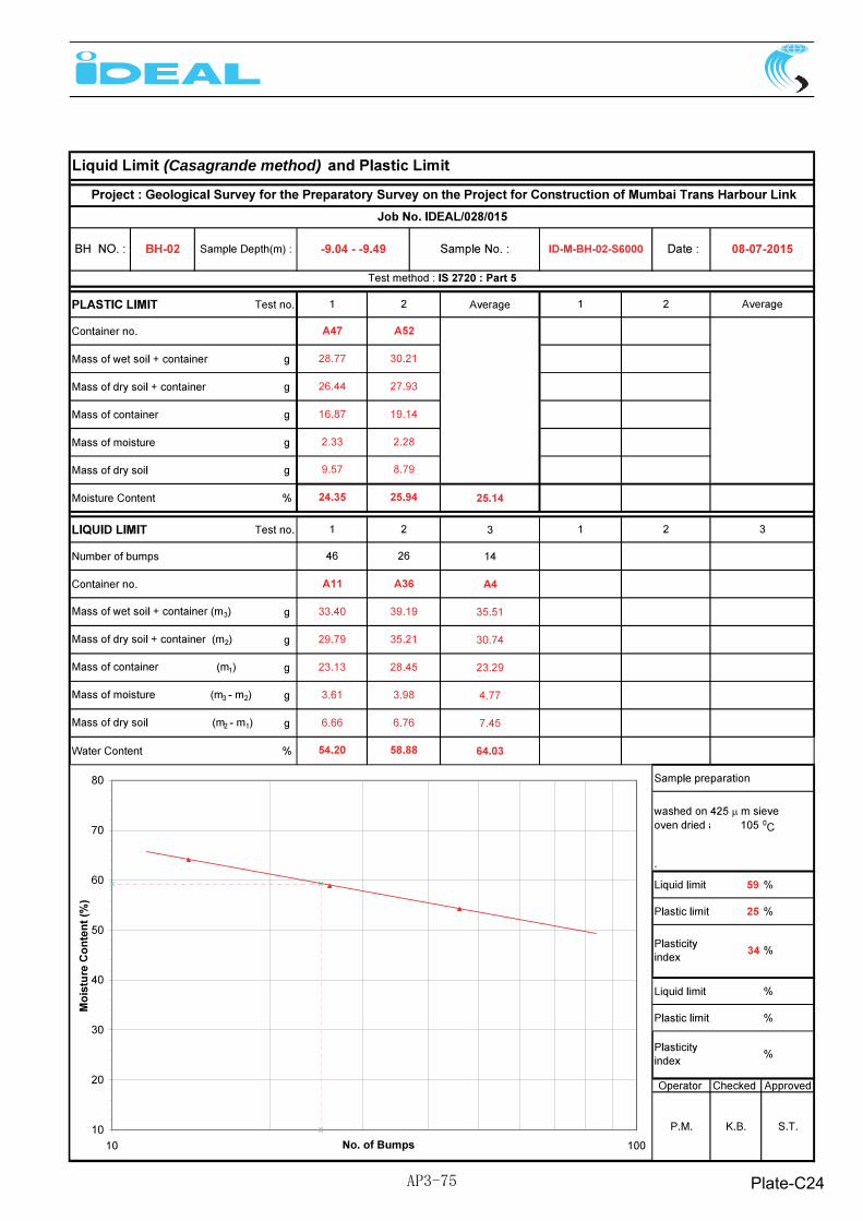
(Casagrande method)
Plate-C24AP3-75

(Casagrande method)
Plate-C25AP3-76

(Casagrande method)
Plate-C26AP3-77

(Casagrande method)
Plate-C27AP3-78

(Casagrande method)
Plate-C28AP3-79

(Casagrande method)
Plate-C29AP3-80

(Casagrande method)
Plate-C30AP3-81

(Casagrande method)
Plate-C31AP3-82
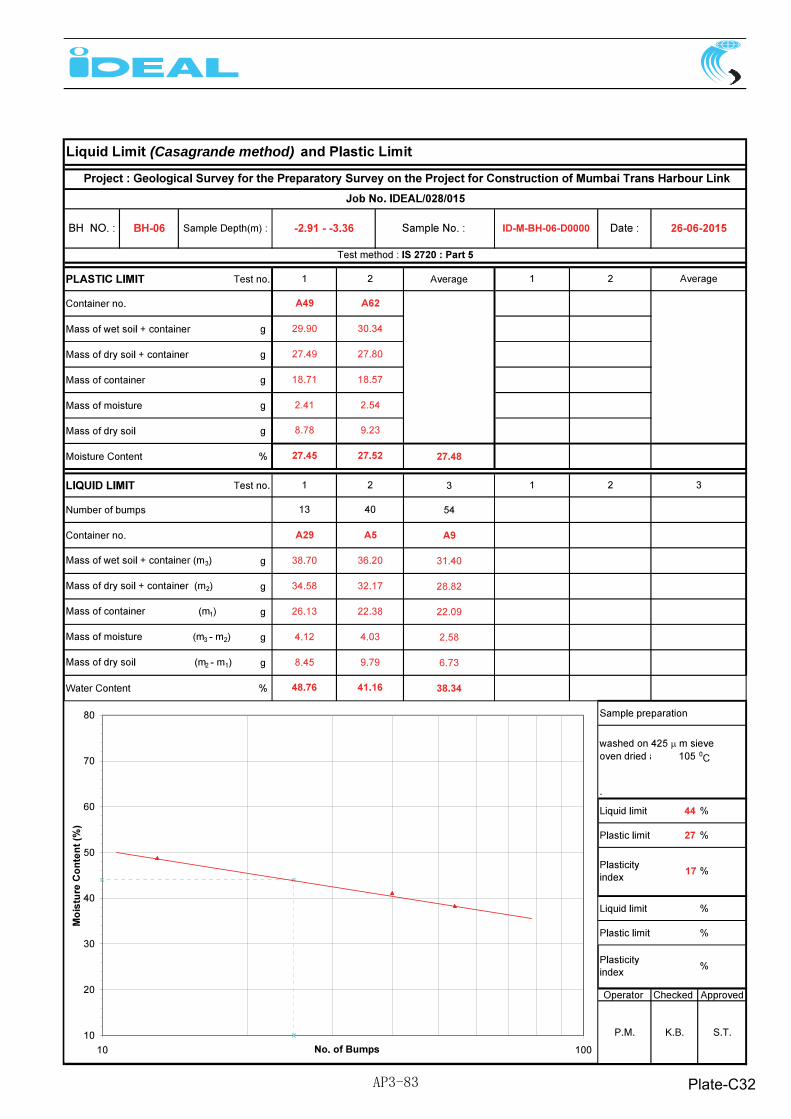
(Casagrande method)
Plate-C32AP3-83

IDEAL-028-015 Geoechnical Investigation Report_Rev 0 11
IDEAL GEOSERVICES PRIVATE LIMITED
APPENDIX-D - STRENGTH TEST RESULTS
AP3-84

AP3-85

AP3-86
IDEAL-028-015 Geoechnical Investigation Report_Rev 0 12
IDEAL GEOSERVICES PRIVATE LIMITED
APPENDIX-E - COMPRESSIBILITY TEST RESULTS
AP3-87

AP3-88

AP3-89

IDEAL-028-015 Geoechnical Investigation Report_Rev 0 13
IDEAL GEOSERVICES PRIVATE LIMITED
APPENDIX-F - CORE BOX PHOTOGRAPHS
AP3-90

AP3-91

AP3-92
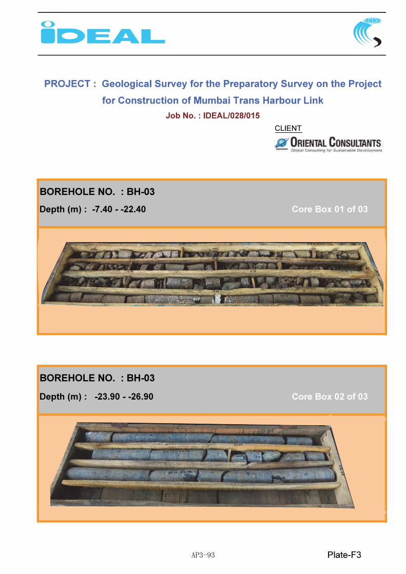
AP3-93

AP3-94

AP3-95

AP3-96

AP3-97