Embed Size (px)
Citation preview
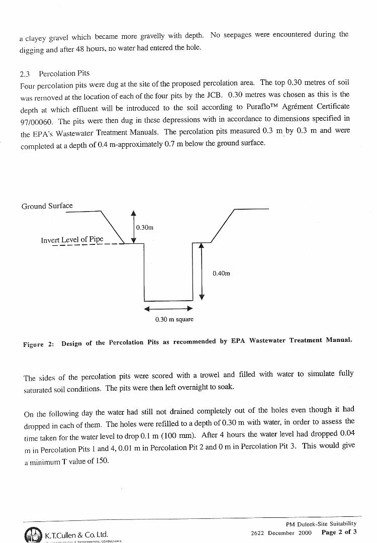
Appendix 9.1.3
Geotechnical Report PM 2009


Meath Waste Management Facility
Carranstown, Co. Meath
Geotechnical Interpretative Report
(Report No. 14039)
Client: Indaver Ireland
Engineer: PM Group Ltd
May 2009
IGSL Ltd

Meath Waste Management Facility, Duleek Geotechnical Interpretative Report
2
DOCUMENT ISSUE REGISTER
Distribution Copies Rev. Date of Issue Report Prepared By:
PM Dublin
Draft - by email (PDF)
A
30 March 2009
PQ
PM Dublin
Final - by email (PDF) & 2 hard copies
B
14 May 2009
PQ
Meath Waste Management Facility, Duleek Geotechnical Interpretative Report
3
TABLE OF CONTENTS
Foreword
1. Introduction 2. Fieldwork 2.1 General 2.2 Rotary Drillholes 2.3 Percolation Tests 2.4 Geophysical Surveying 3. Laboratory Testing 4. Ground Conditions & Engineering Properties 4.1 Ground Profile 4.2 Glacial Deposits
4.3 Bedrock 4.4 Groundwater 5. Discussion & Recommendations 5.1 General 5.2 Bearing Capacity 5.3 Foundations 5.4 Floor Slabs 5.5 Excavatability 5.6 Earthworks & Modification of Glacial Soils 5.7 Pavement 5.8 Groundwater 5.9 Slopes 5.10 Ground Retention 5.11 Karst Weathering 5.12 Geotechnical Risk Management References
FIGURES
Figure 1 - SPT Data Plot Figure 2 - Shear Wave Velocity Data Plot Figure 3 - Small Strain Stiffness (GMax) Plot
TABLES Table 1 - Summary Details of Consolidated Undrained Triaxial Tests Table 2 - Summary Details of Rotary Core Drillholes Table 3 - Summary Details of Safe Bearing Capacities Table 4 - Suggested Foundation Solutions Table 5 - Sample of Geotechnical Risk Register / Log PLATES Plate 1 - Example of Geobor Recovery in Glacial Till Plate 2 - Example of Limestone Bedrock at Waste Bunker
Meath Waste Management Facility, Duleek Geotechnical Interpretative Report
4
FOREWORD
The following conditions and notes on site investigation procedures should be read in conjunction with this geotechnical report. General The ground investigation works for the Meath Waste Management Facility, Duleek have been carried out in accordance with BS 5930 (1990) and the IEI Specification & Related Documents for Ground Investigation in Ireland (2006). Recommendations made and opinions expressed in this report are based on the strata observed in the exploratory holes, together with the results of in-situ and laboratory test data. No responsibility can be held for conditions which have not been revealed by exploratory work, or which occur between exploratory hole locations. Whilst the report may suggest the likely configuration of strata, both between exploratory hole locations, or below the maximum depth of the investigation, this is only indicative, and liability cannot be accepted for its accuracy. Unless specifically stated, no account has been taken of possible subsidence due to mineral extraction below or close to the site.
Disclaimer The geotechnical interpretative report has been prepared for Project Management Group / Indaver Ireland and the information should not be used without prior approval or written permission of either party. The recommendations developed in this report are based on the IGSL factual ground investigation data (IGSL Project No. 14039), Byrne Looby Geotechnical Assessment Report (B580) and Apex Geophysical Report. IGSL Ltd accepts no responsibility or liability for this document being used other than for the purposes for which it was intended.
Meath Waste Management Facility, Duleek Geotechnical Interpretative Report
5
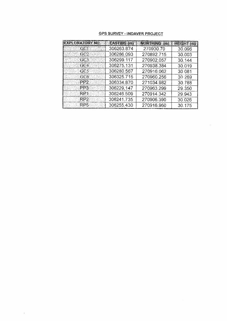
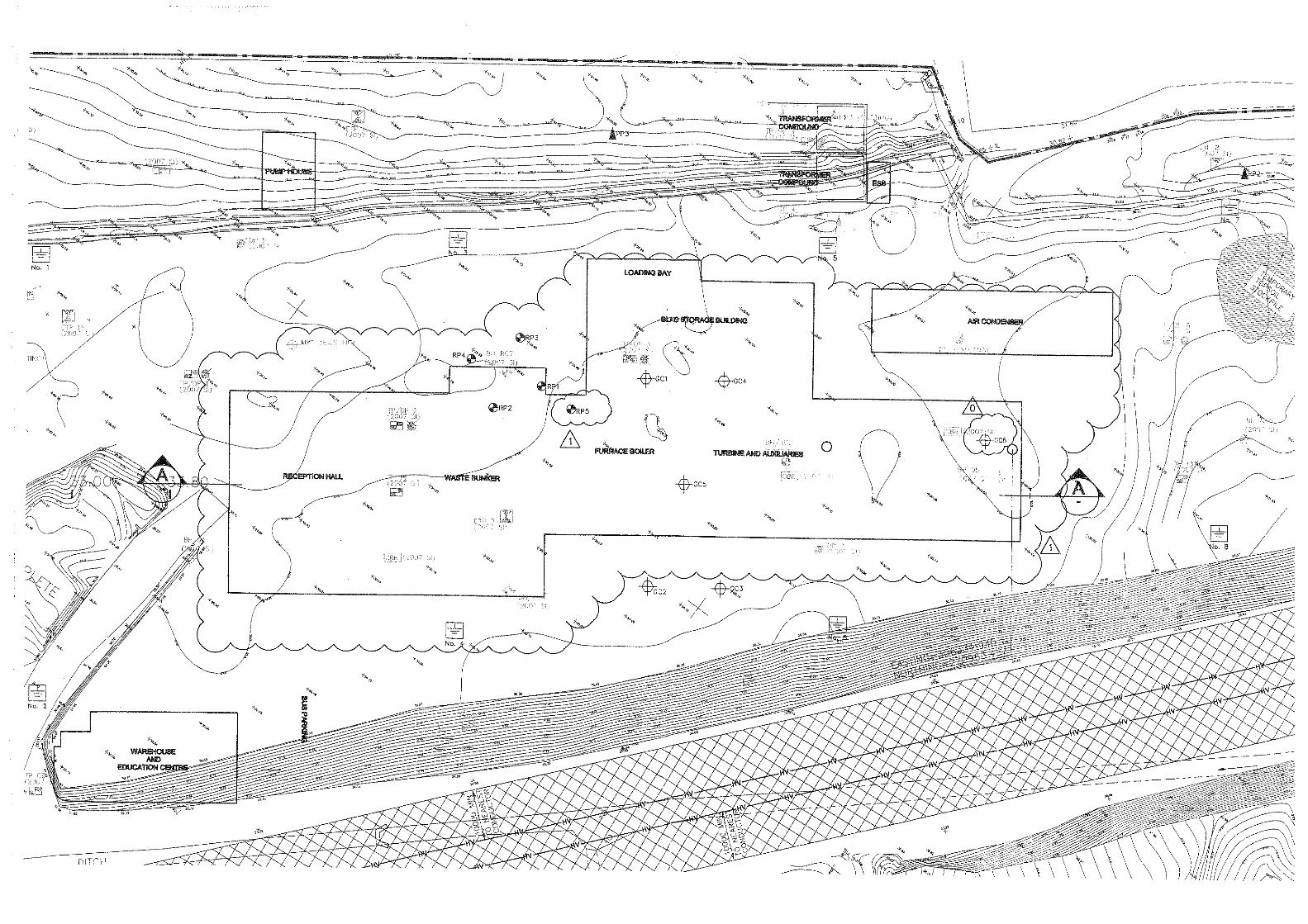
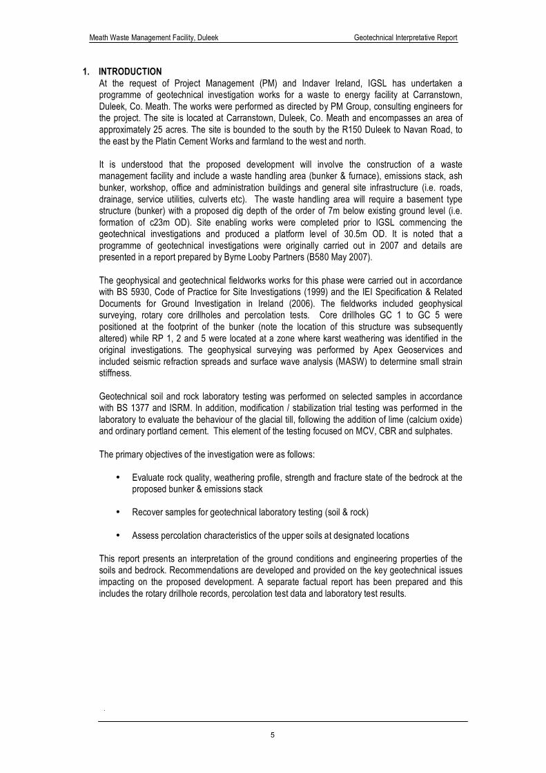
1. INTRODUCTION At the request of Project Management (PM) and Indaver Ireland, IGSL has undertaken a programme of geotechnical investigation works for a waste to energy facility at Carranstown, Duleek, Co. Meath. The works were performed as directed by PM Group, consulting engineers for the project. The site is located at Carranstown, Duleek, Co. Meath and encompasses an area of approximately 25 acres. The site is bounded to the south by the R150 Duleek to Navan Road, to the east by the Platin Cement Works and farmland to the west and north. It is understood that the proposed development will involve the construction of a waste management facility and include a waste handling area (bunker & furnace), emissions stack, ash bunker, workshop, office and administration buildings and general site infrastructure (i.e. roads, drainage, service utilities, culverts etc). The waste handling area will require a basement type structure (bunker) with a proposed dig depth of the order of 7m below existing ground level (i.e. formation of c23m OD). Site enabling works were completed prior to IGSL commencing the geotechnical investigations and produced a platform level of 30.5m OD. It is noted that a programme of geotechnical investigations were originally carried out in 2007 and details are presented in a report prepared by Byrne Looby Partners (B580 May 2007). The geophysical and geotechnical fieldworks works for this phase were carried out in accordance with BS 5930, Code of Practice for Site Investigations (1999) and the IEI Specification & Related Documents for Ground Investigation in Ireland (2006). The fieldworks included geophysical surveying, rotary core drillholes and percolation tests. Core drillholes GC 1 to GC 5 were positioned at the footprint of the bunker (note the location of this structure was subsequently altered) while RP 1, 2 and 5 were located at a zone where karst weathering was identified in the original investigations. The geophysical surveying was performed by Apex Geoservices and included seismic refraction spreads and surface wave analysis (MASW) to determine small strain stiffness. Geotechnical soil and rock laboratory testing was performed on selected samples in accordance with BS 1377 and ISRM. In addition, modification / stabilization trial testing was performed in the laboratory to evaluate the behaviour of the glacial till, following the addition of lime (calcium oxide) and ordinary portland cement. This element of the testing focused on MCV, CBR and sulphates.
The primary objectives of the investigation were as follows:
• Evaluate rock quality, weathering profile, strength and fracture state of the bedrock at the
proposed bunker & emissions stack • Recover samples for geotechnical laboratory testing (soil & rock)
• Assess percolation characteristics of the upper soils at designated locations
This report presents an interpretation of the ground conditions and engineering properties of the soils and bedrock. Recommendations are developed and provided on the key geotechnical issues impacting on the proposed development. A separate factual report has been prepared and this includes the rotary drillhole records, percolation test data and laboratory test results.
Meath Waste Management Facility, Duleek Geotechnical Interpretative Report
6
2. FIELDWORK 2.1 General The fieldworks were carried out during the period February 2009 and comprised the following:
o Rotary core drillholes (9 No.) o Percolation tests (2 No.) o Geophysical surveying
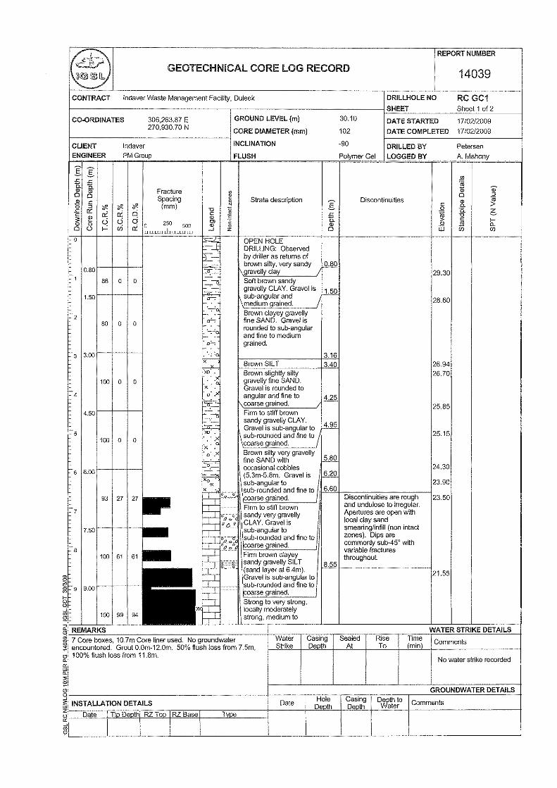
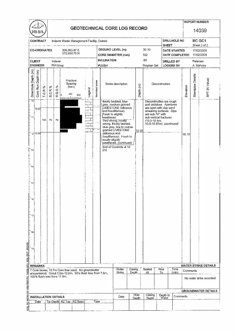
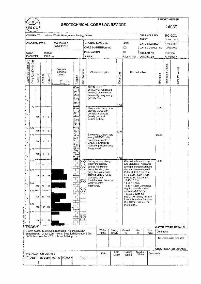
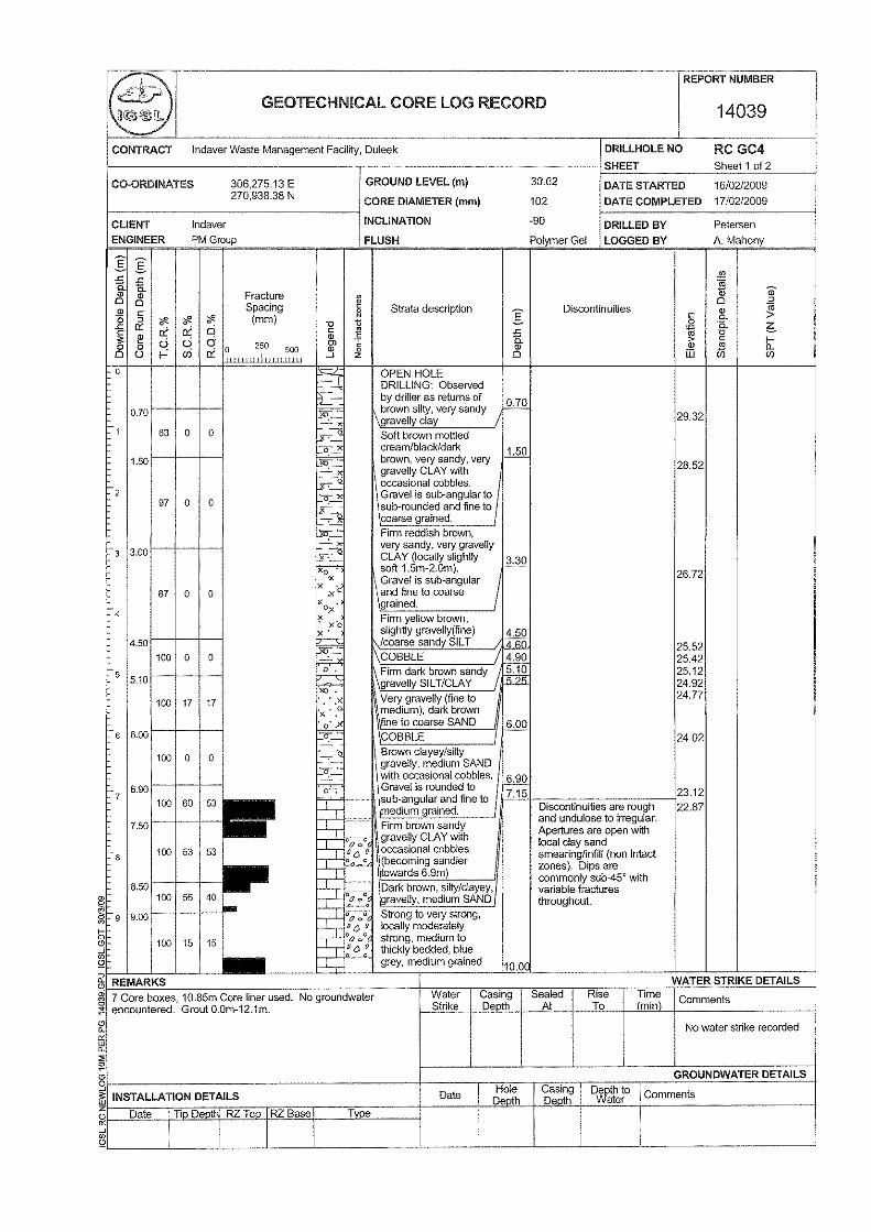
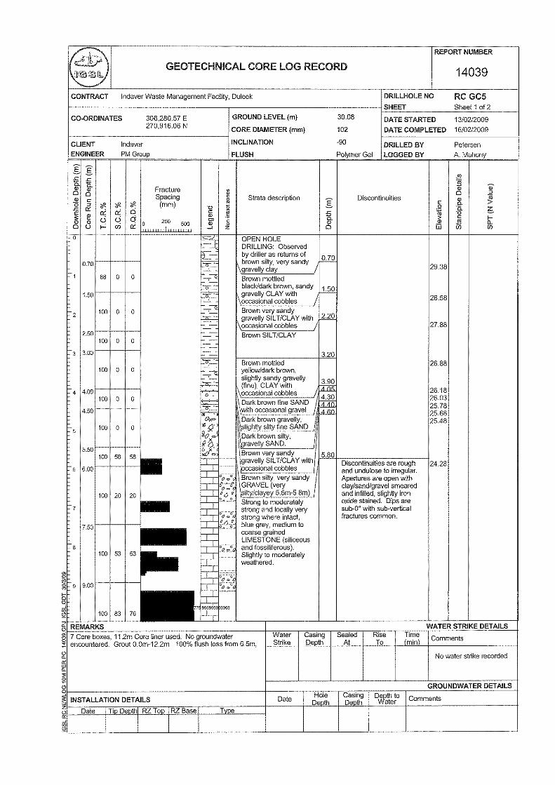
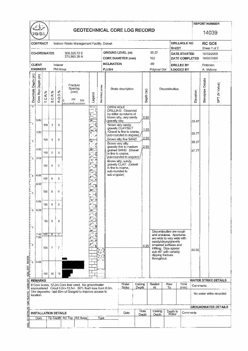
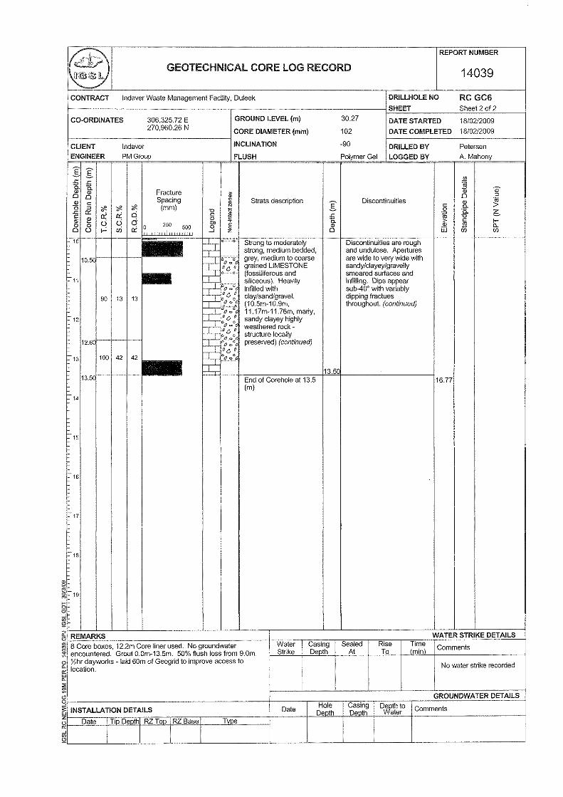
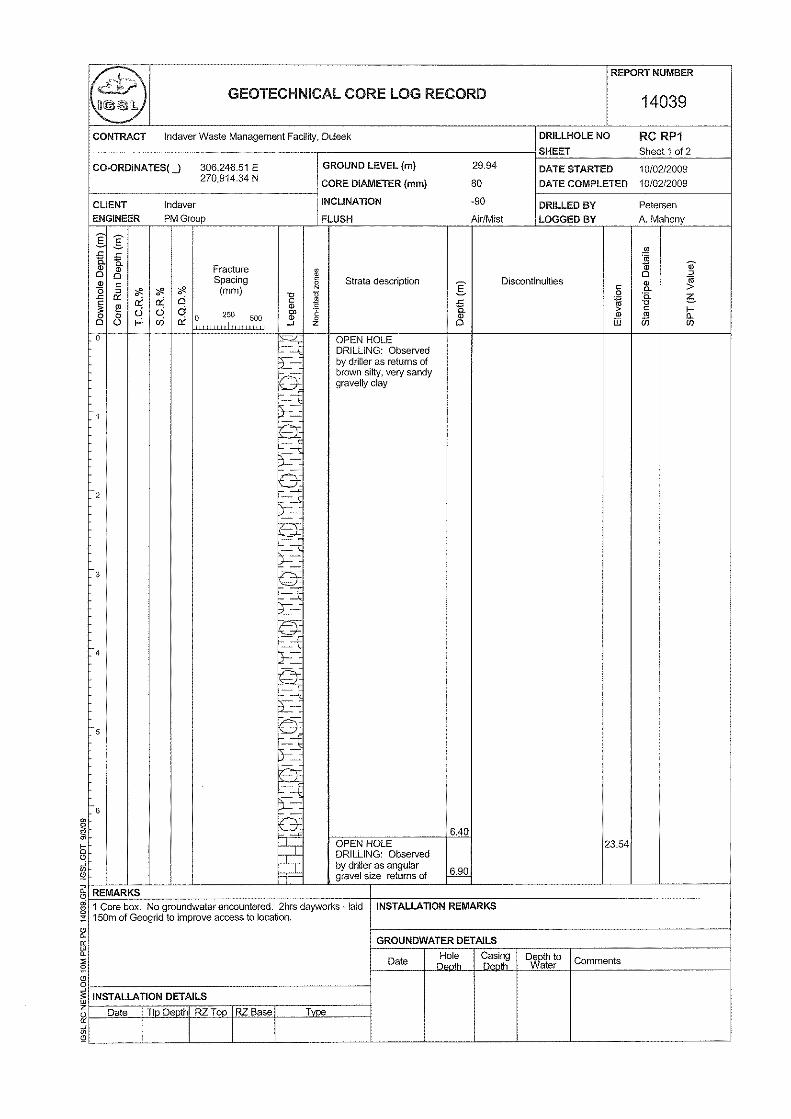
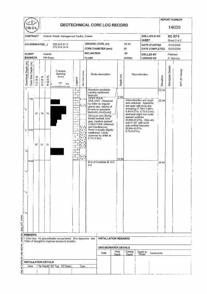
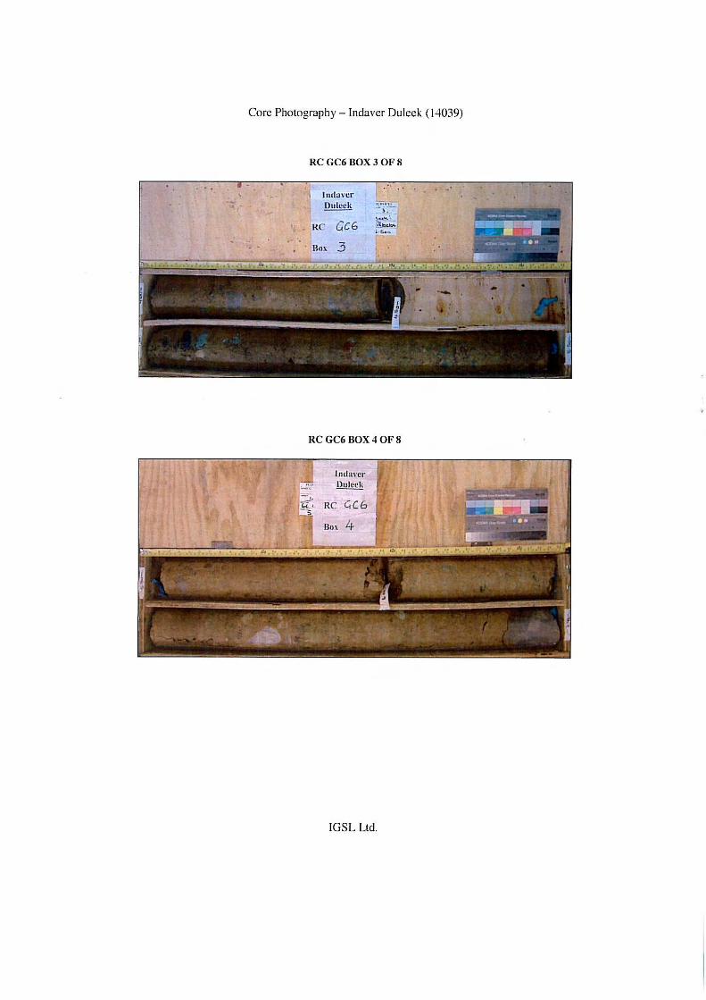
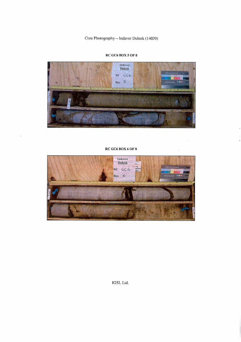
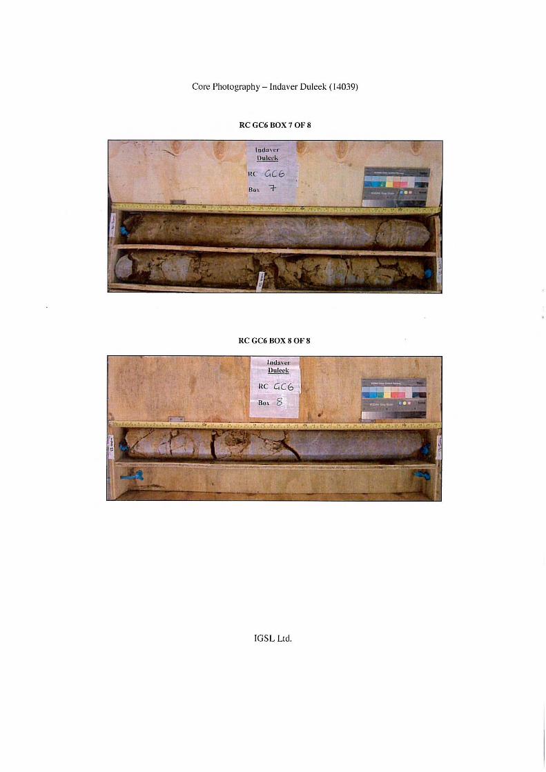
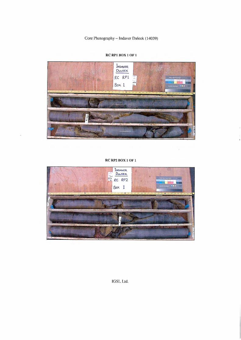
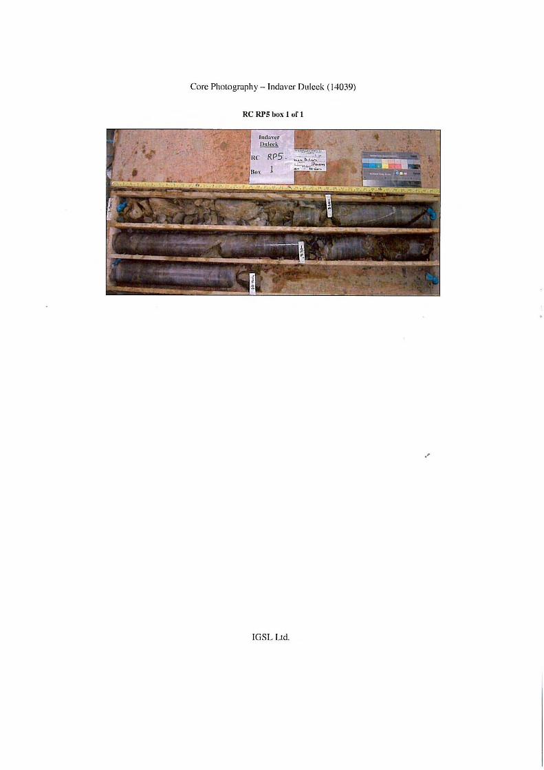
2.2 Rotary Drillholes Rotary drilling was undertaken at nine locations using a top drive Knebel rig. Geobor core drilling methods were utilized at six locations (denoted GC 1 to GC 6) with conventional air mist drilling employed at three locations (RP 1, 2 & 5). The Geobor drilling system used polymer gel flush and recirculation tanks, with the emphasis on high quality recovery in the glacial soils and upper bedrock zone. The Geobor coring produced 102mm diameter cores while the conventional coring produced 80mm diameter cores using air mist flush. Recovery in the Geobor holes was excellent with 100% recovery in the majority of the runs. The Geobor drillholes achieved depths of between 11.80 and 15.10m while each of the conventional holes terminated at depths of 10.50m. Each of the core drillholes were backfilled with cement/bentonite grout (tremmied) as directed by PM.
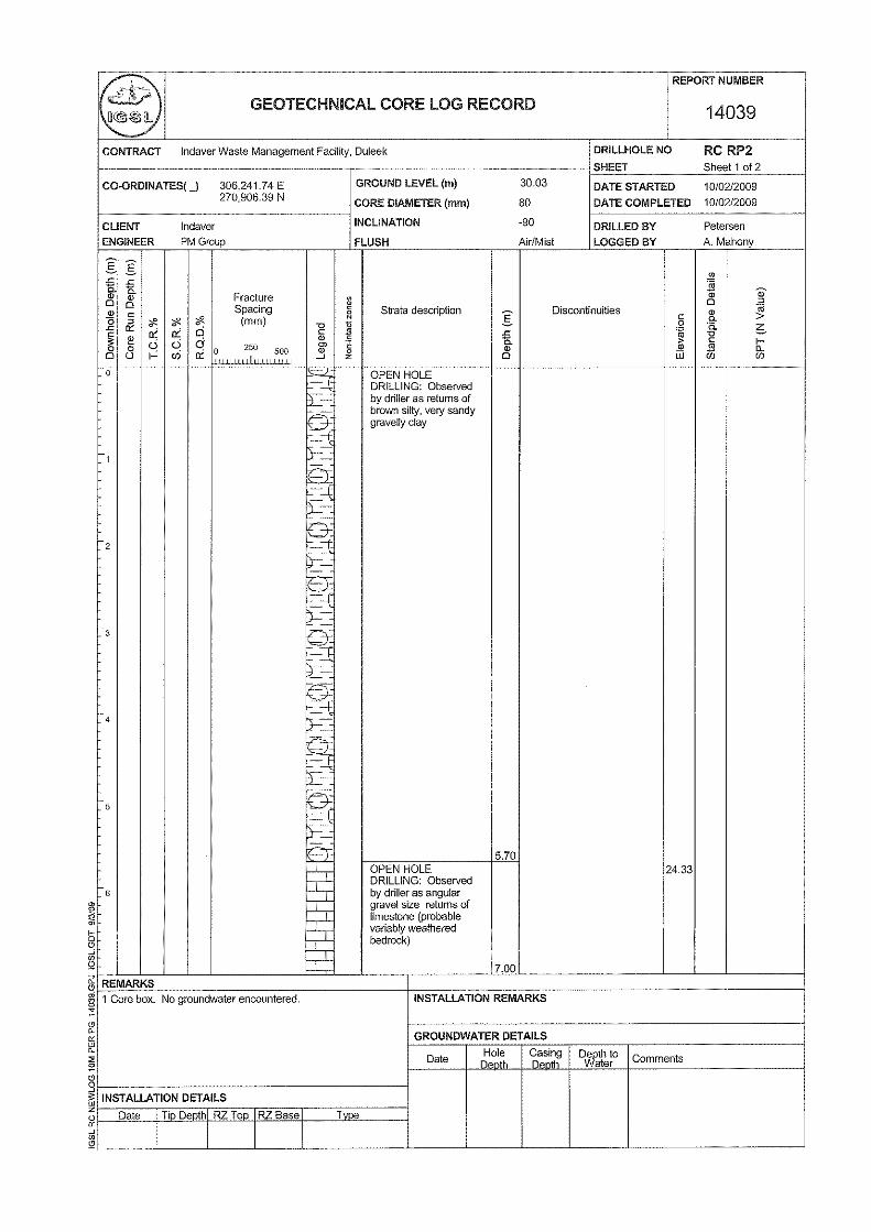
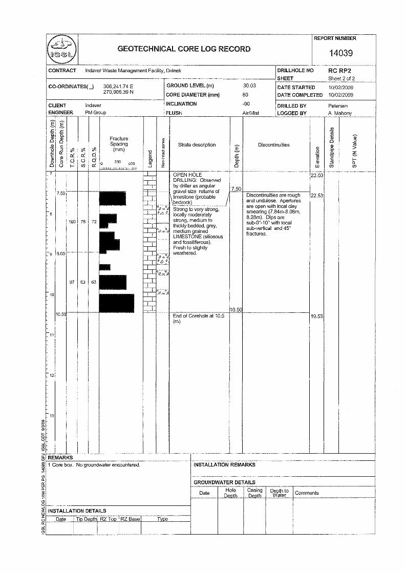
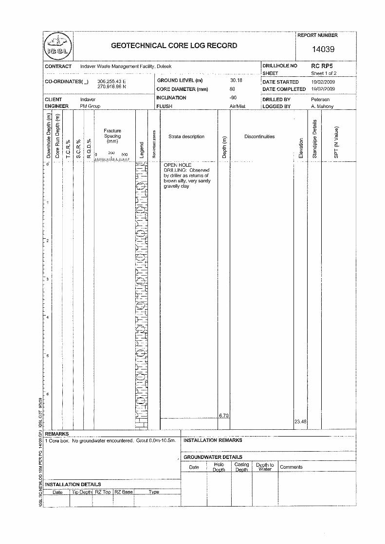
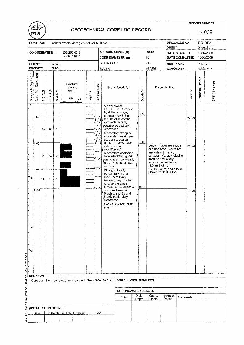
The rock cores were placed in 3m capacity timber boxes and logged by an IGSL engineering geologist. This included photography of the cores with a digital camera. The core log records are presented in Appendices 1 and 2 of the factual report and include engineering geological descriptions of the rock cores, details of the bedding / discontinuities and mechanical indices (TCR, SCR and RQD's) for each core run. Where rock core was recovered, a graphic fracture log is also presented alongside the mechanical indices. This illustrates the fracture state of the rock cores and allows easy identification of highly fractured / non-intact zones and discontinuity spacings. It should be noted that no correction for dip of the joints has been made and that the spacings shown are successive joint / core intersections within the core.
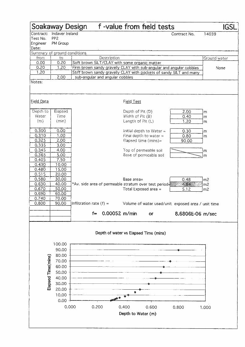
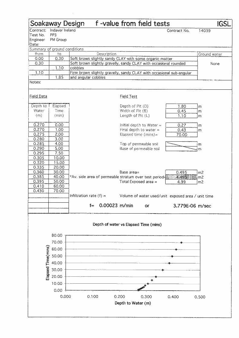
2.3 Percolation Tests Percolation or soakaway tests were performed at two locations to evaluate the infiltration potential of the upper soils. The tests were conducted in accordance with BRE 365 guidelines and the data sheets are presented in Appendix 3 of the factual report. The infiltration rate values (F Values) were calculated using the field data and are shown on each of the logs.
2.4 Geophysical Surveying Geophysical surveying was carried out by Apex Geoservices and included resistivity profiling, seismic refraction spreads and multi-channel analysis of surface waves to assess soil stiffness (GMax v depth). Details of the methodologies used, x-sections / profiles and maps are presented in a separate report by Apex Geoservices.
Meath Waste Management Facility, Duleek Geotechnical Interpretative Report
7
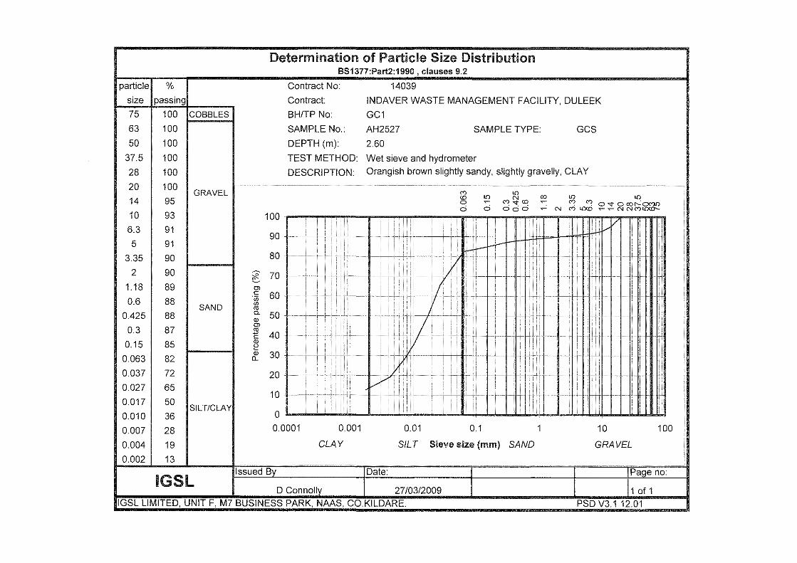
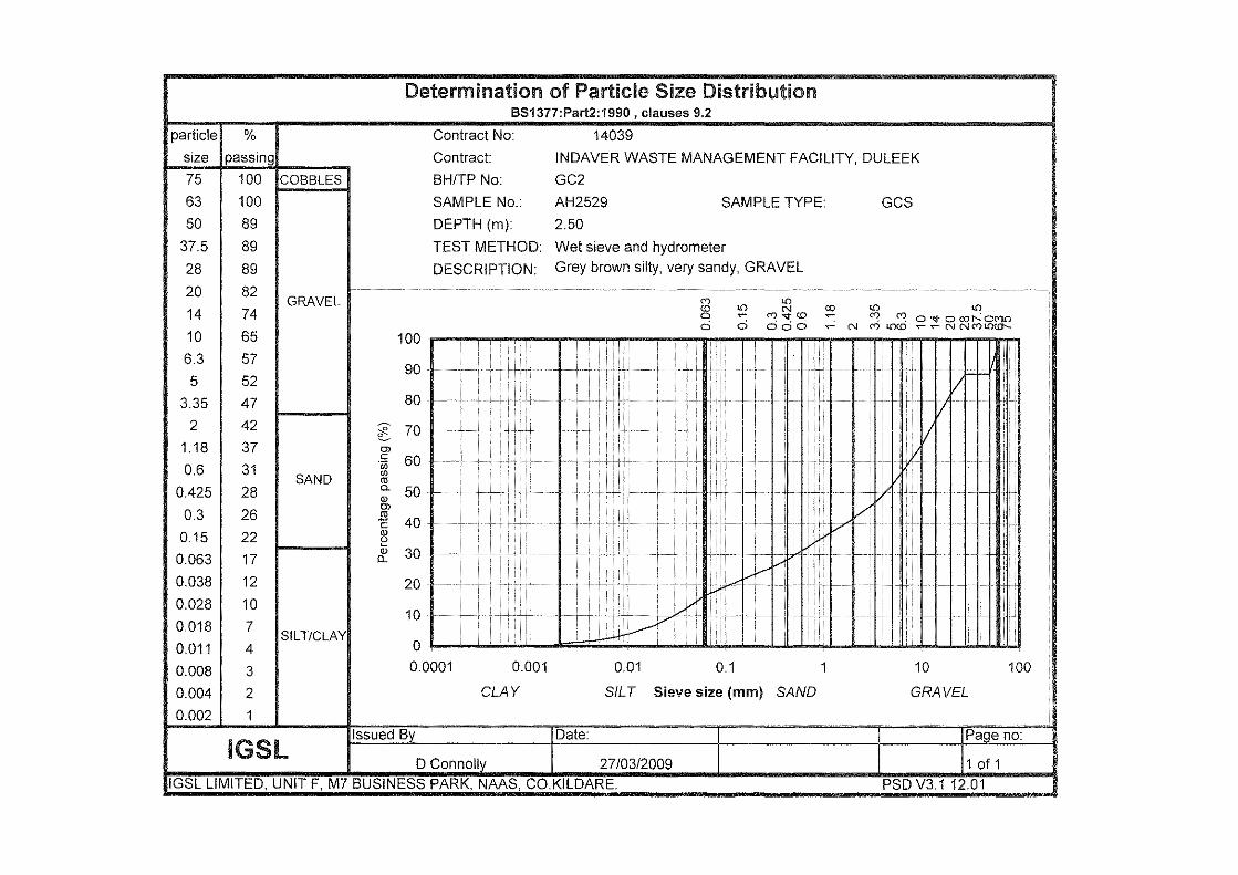
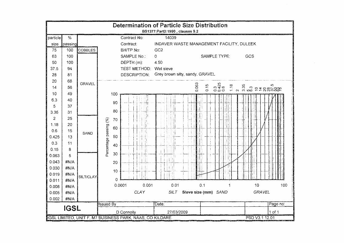
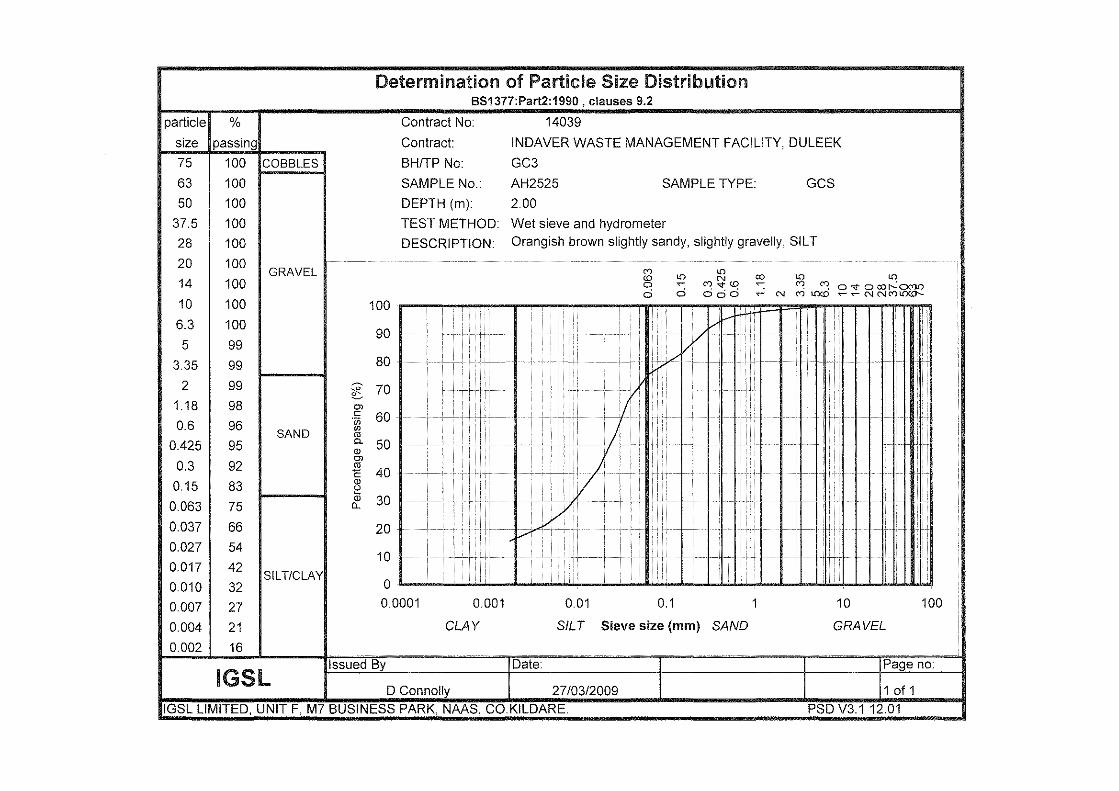
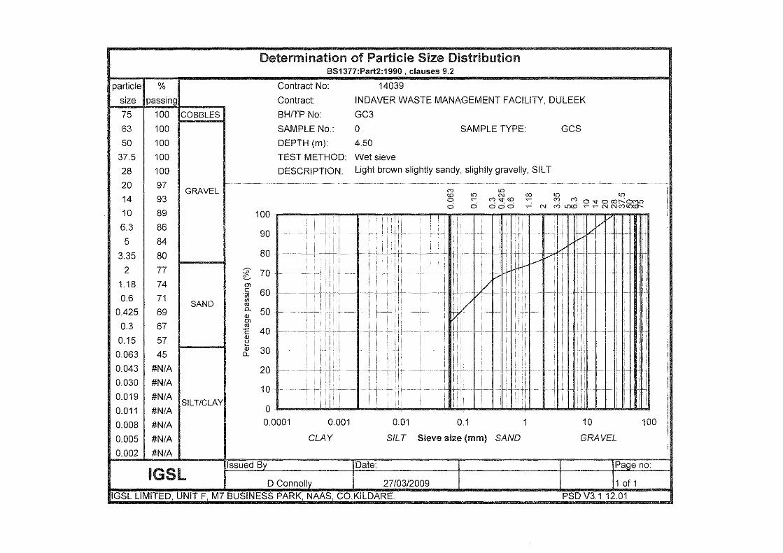
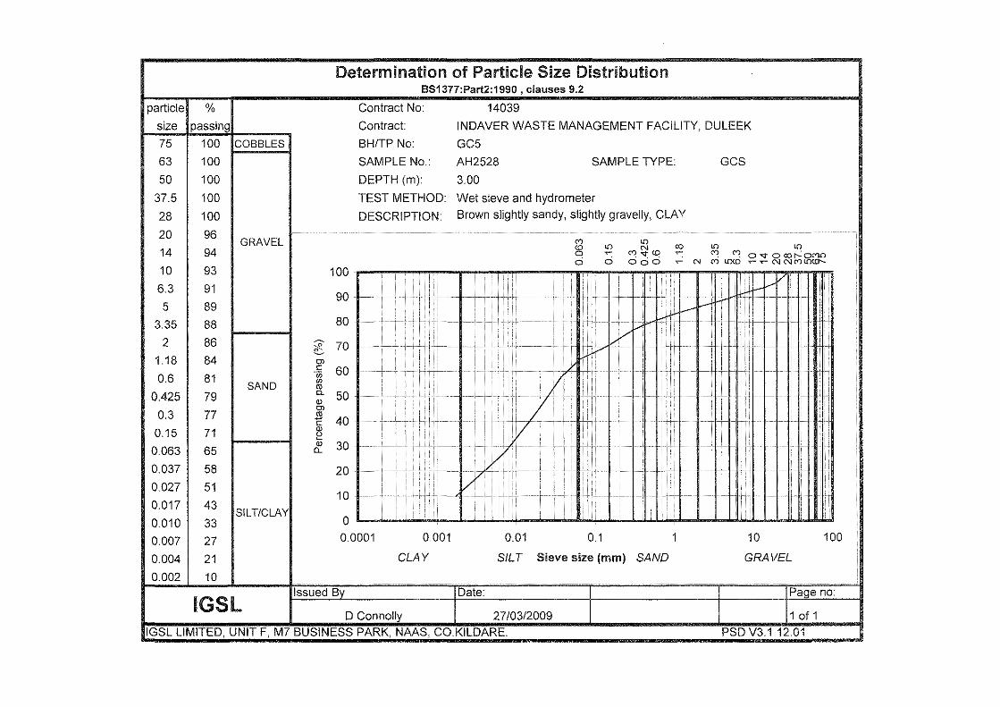
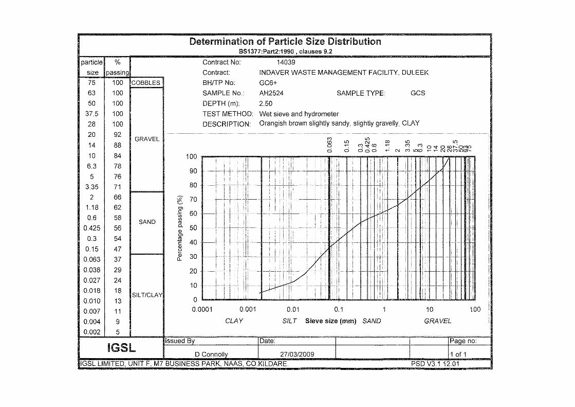
3. LABORATORY TESTING Geotechnical soil laboratory testing was performed on selected Geobor core samples in accordance with BS 1377 (1990). The soils testing included the following and results are presented in Appendix 4 of the factual report.
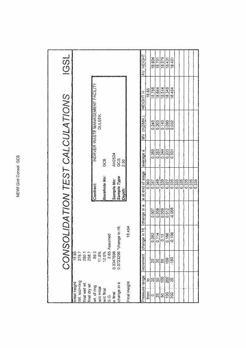
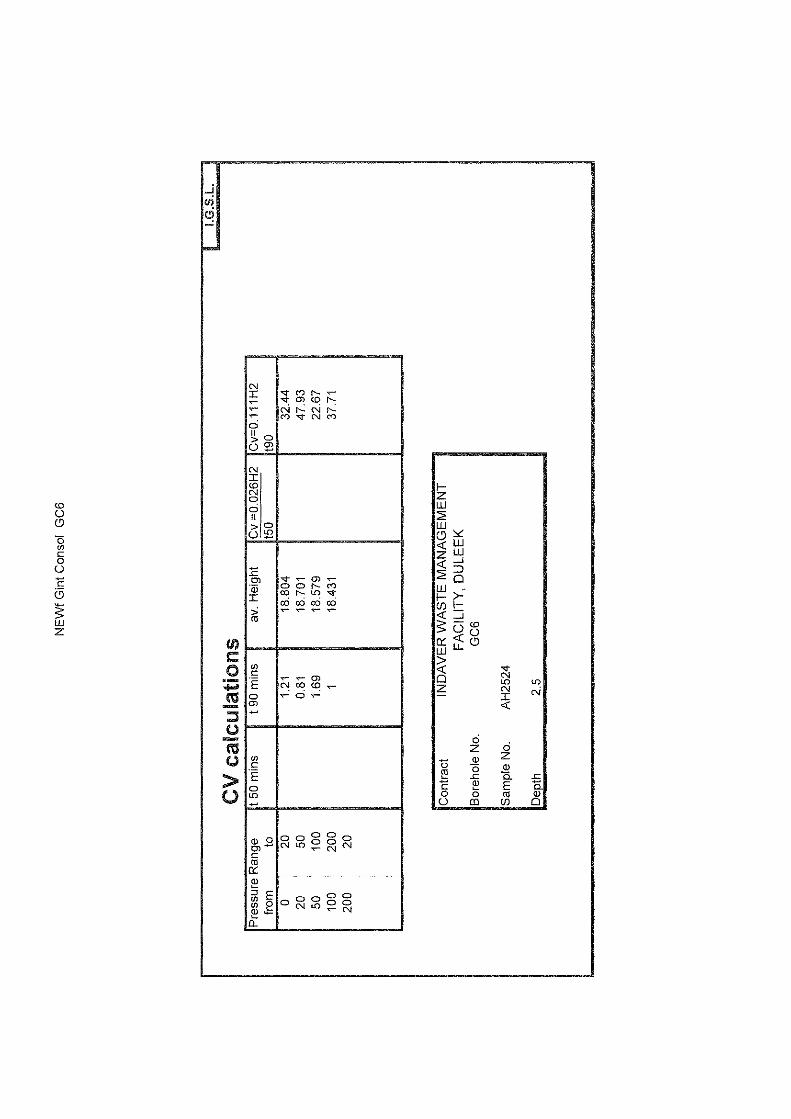
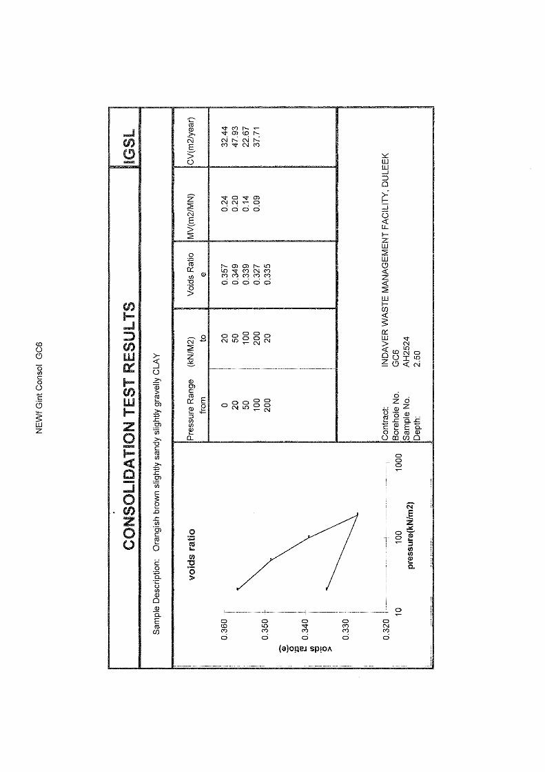
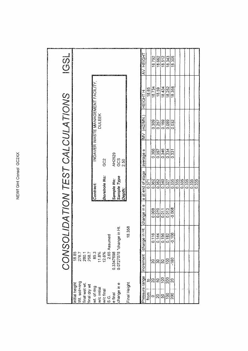
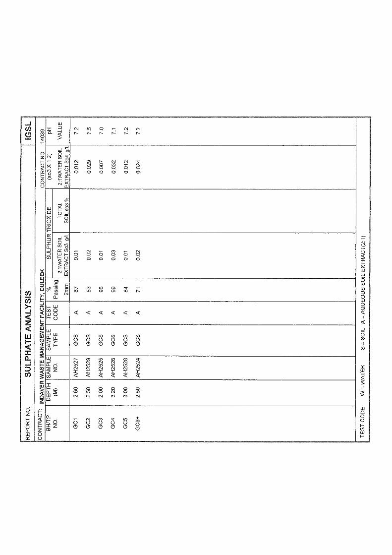
o Moisture contents o Particle size analysis o Atterberg Limits (Liquid & Plastic Limits) o Consolidated quick undrained triaxial tests o Consolidation (oedometer) tests o pH & sulphates
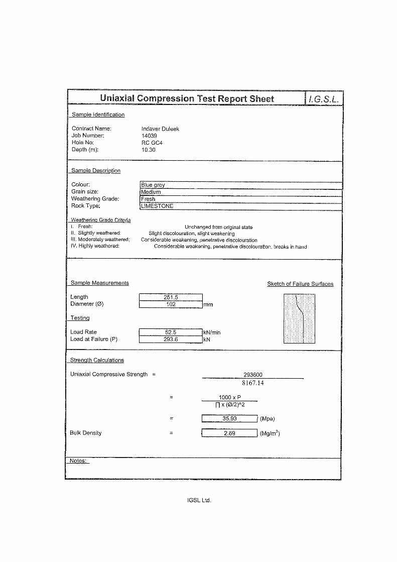
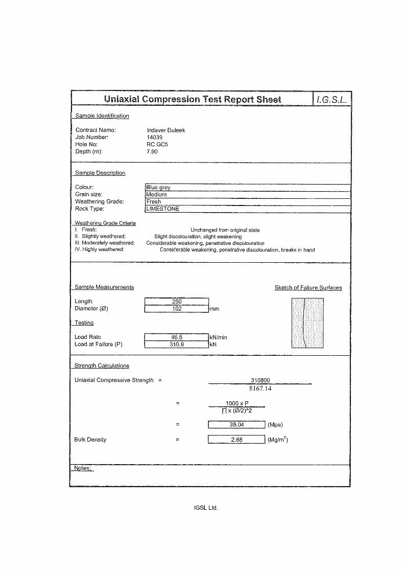
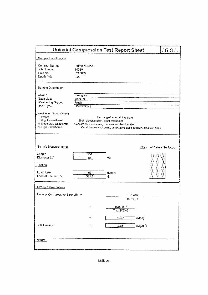
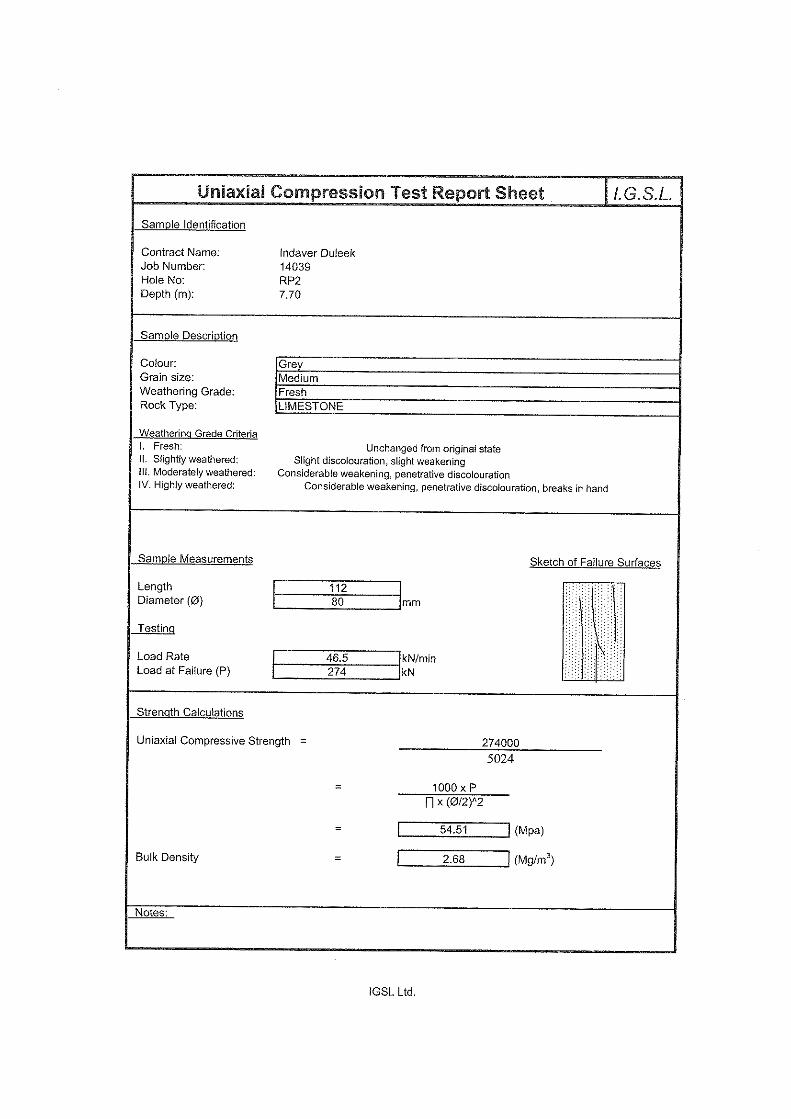
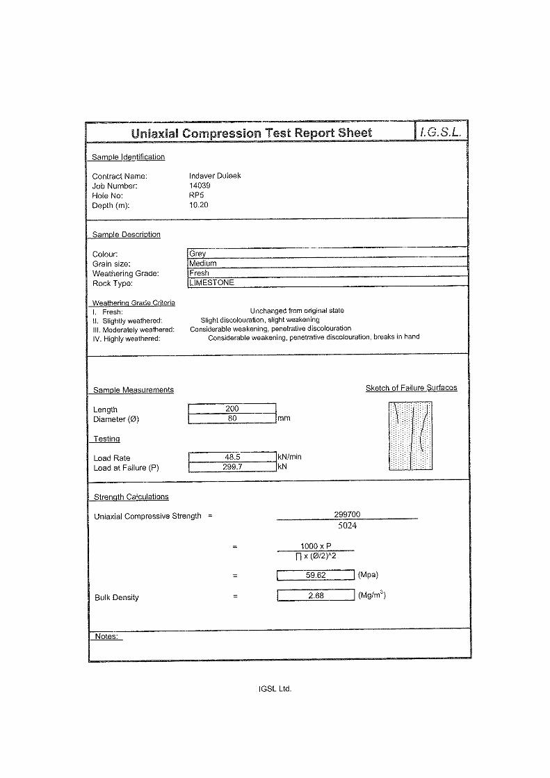
Soil modification / stabilization testing was carried out on samples of the glacial till recovered from stockpiles and at the bunker footprint. The results of these tests are presented in Appendix 6 of the factual report. Rock testing was undertaken on representative core samples and focused on Point Load Strength Index (PLSI)) and unconfined compressive strength (UCS) tests in accordance with ISRM. The results of the rock testing are presented in Appendix 5 of the factual report.
Meath Waste Management Facility, Duleek Geotechnical Interpretative Report
8
4. GROUND CONDITIONS & ENGINEERING PROPERTIES 4.1 Ground Profile The exploratory holes have revealed the ground conditions at this site to comprise:
o Glacial deposits
o Limestone Bedrock
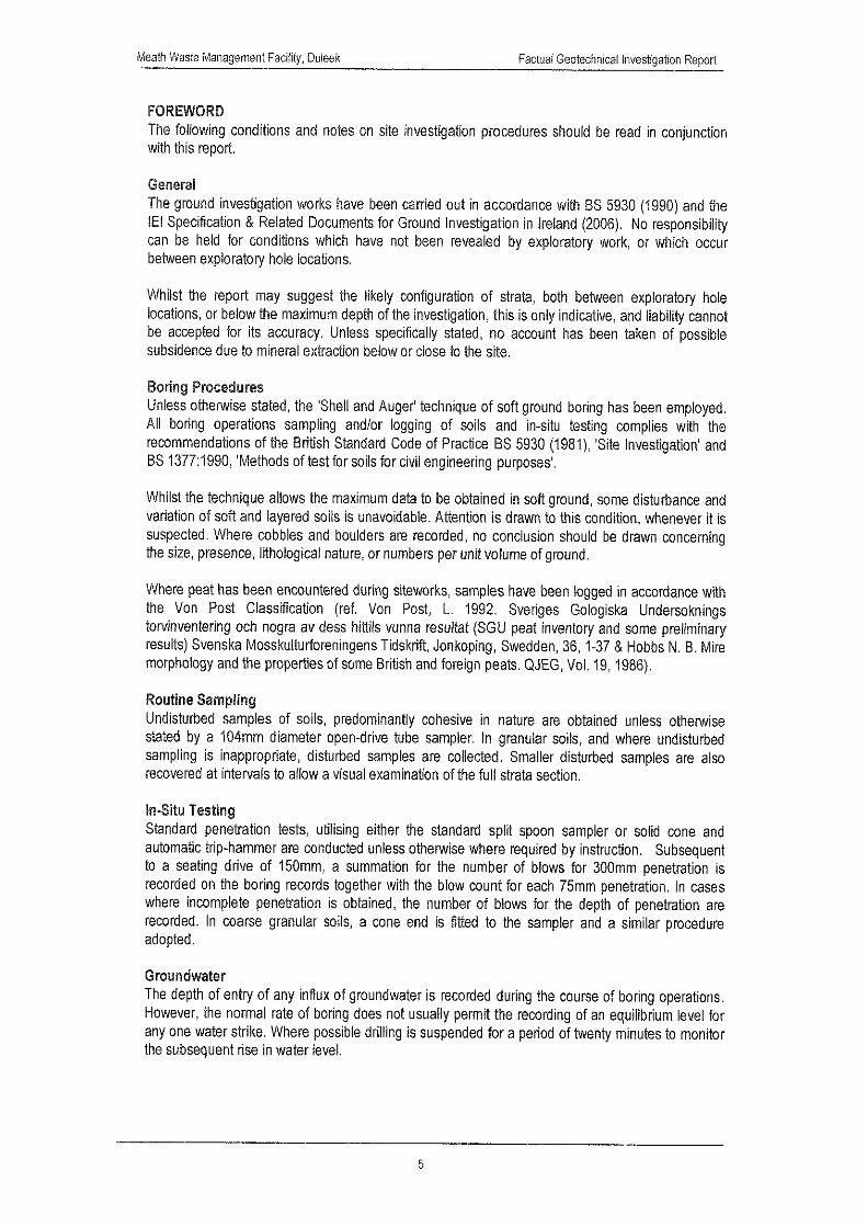
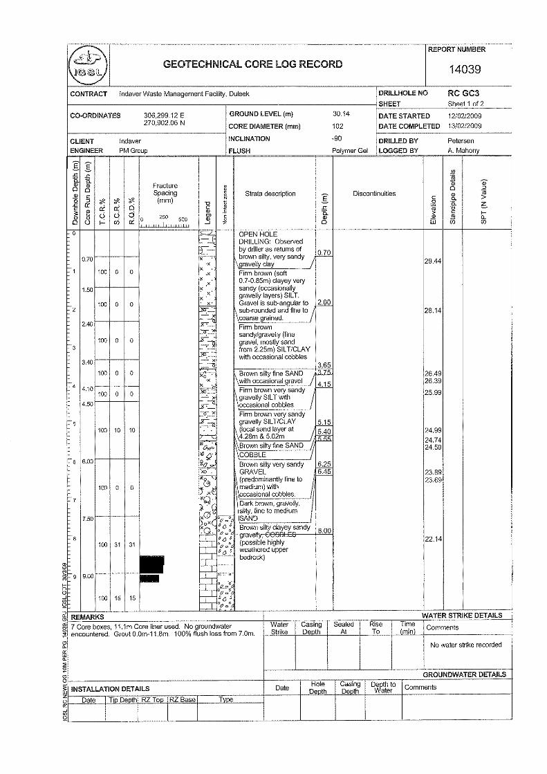
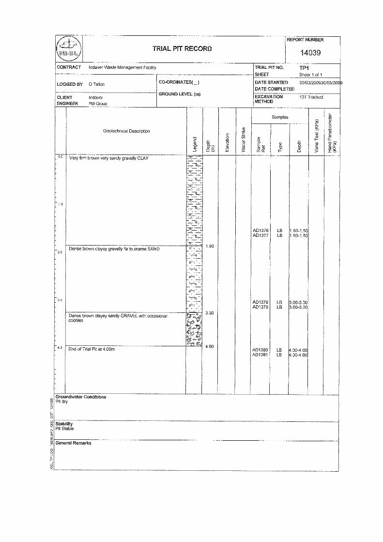
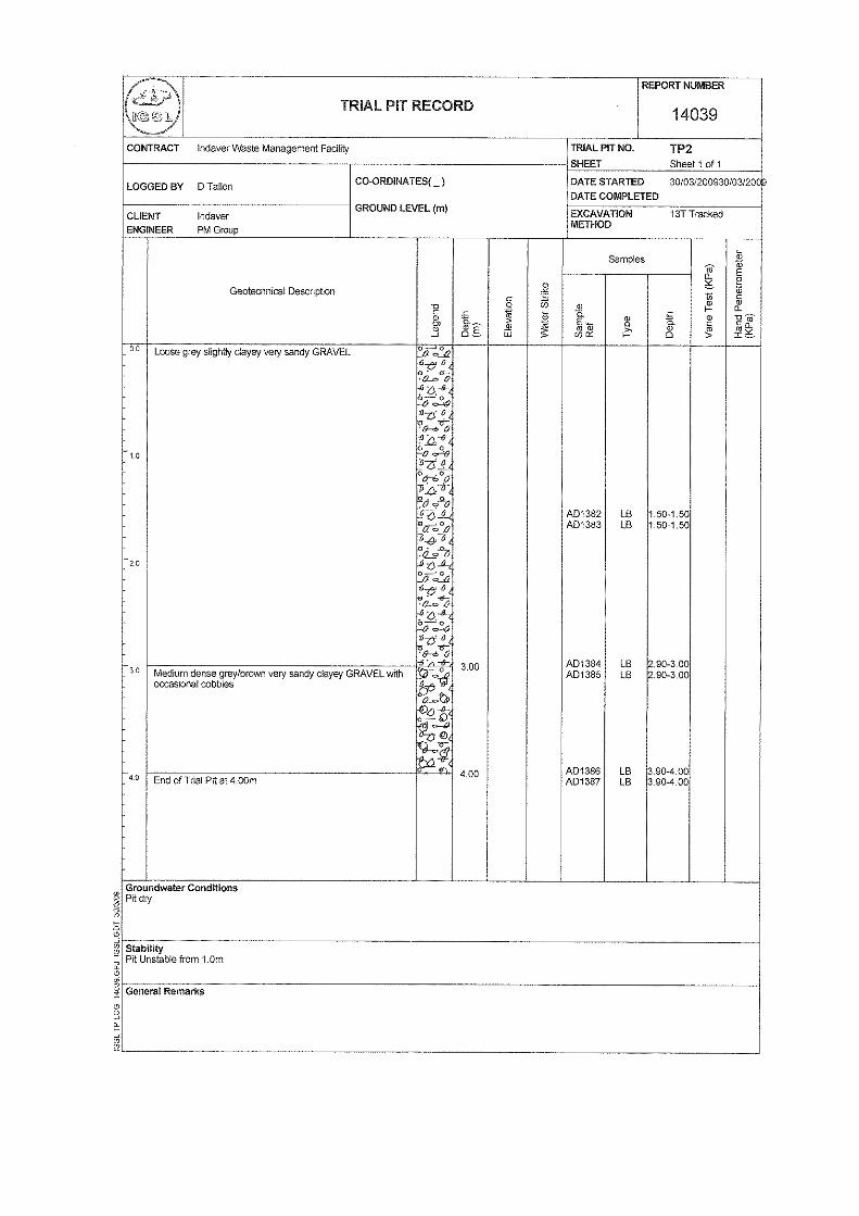
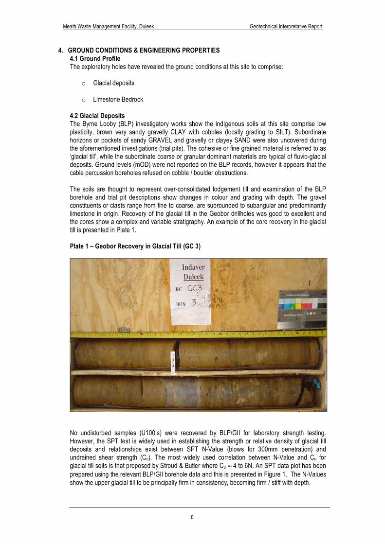
4.2 Glacial Deposits The Byrne Looby (BLP) investigatory works show the indigenous soils at this site comprise low plasticity, brown very sandy gravelly CLAY with cobbles (locally grading to SILT). Subordinate horizons or pockets of sandy GRAVEL and gravelly or clayey SAND were also uncovered during the aforementioned investigations (trial pits). The cohesive or fine grained material is referred to as ‘glacial till’, while the subordinate coarse or granular dominant materials are typical of fluvio-glacial deposits. Ground levels (mOD) were not reported on the BLP records, however it appears that the cable percussion boreholes refused on cobble / boulder obstructions. The soils are thought to represent over-consolidated lodgement till and examination of the BLP borehole and trial pit descriptions show changes in colour and grading with depth. The gravel constituents or clasts range from fine to coarse, are subrounded to subangular and predominantly limestone in origin. Recovery of the glacial till in the Geobor drillholes was good to excellent and the cores show a complex and variable stratigraphy. An example of the core recovery in the glacial till is presented in Plate 1. Plate 1 – Geobor Recovery in Glacial Till (GC 3)
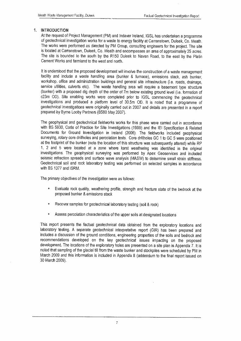
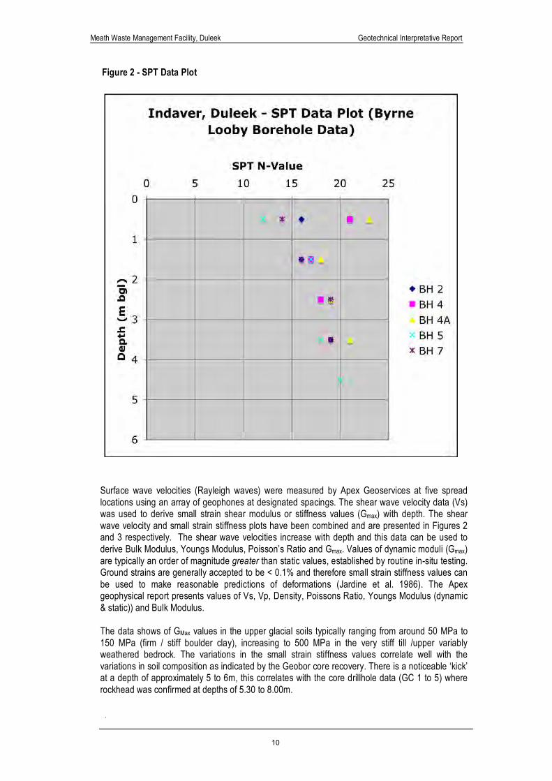
No undisturbed samples (U100’s) were recovered by BLP/GII for laboratory strength testing. However, the SPT test is widely used in establishing the strength or relative density of glacial till deposits and relationships exist between SPT N-Value (blows for 300mm penetration) and undrained shear strength (Cu). The most widely used correlation between N-Value and Cu for glacial till soils is that proposed by Stroud & Butler where Cu ≈ 4 to 6N. An SPT data plot has been prepared using the relevant BLP/GII borehole data and this is presented in Figure 1. The N-Values show the upper glacial till to be principally firm in consistency, becoming firm / stiff with depth.
Meath Waste Management Facility, Duleek Geotechnical Interpretative Report
9
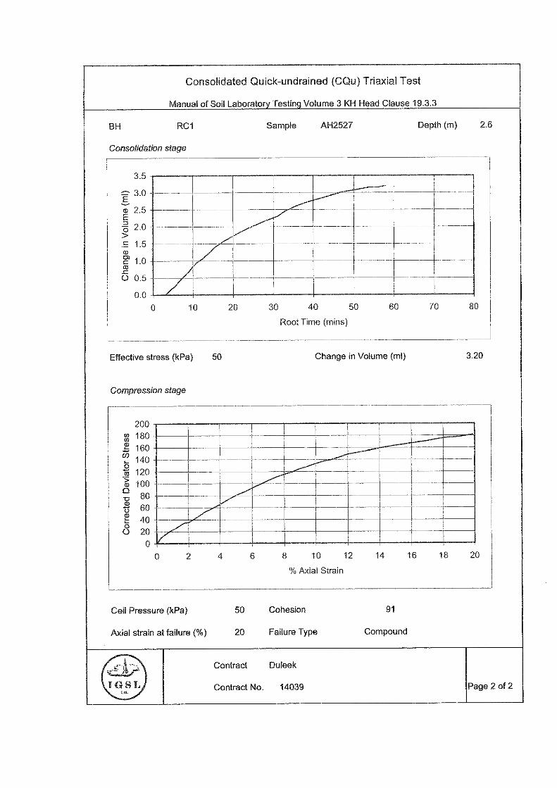
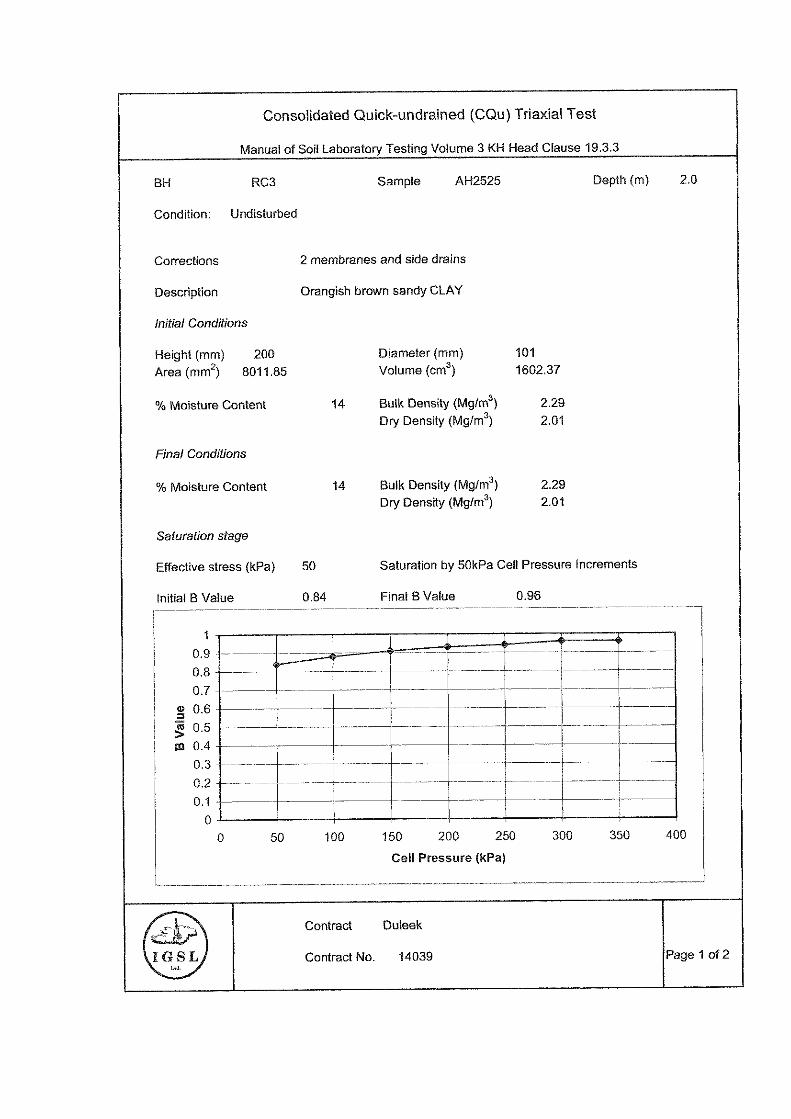
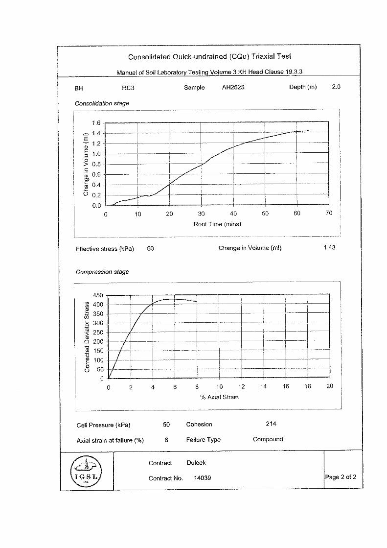
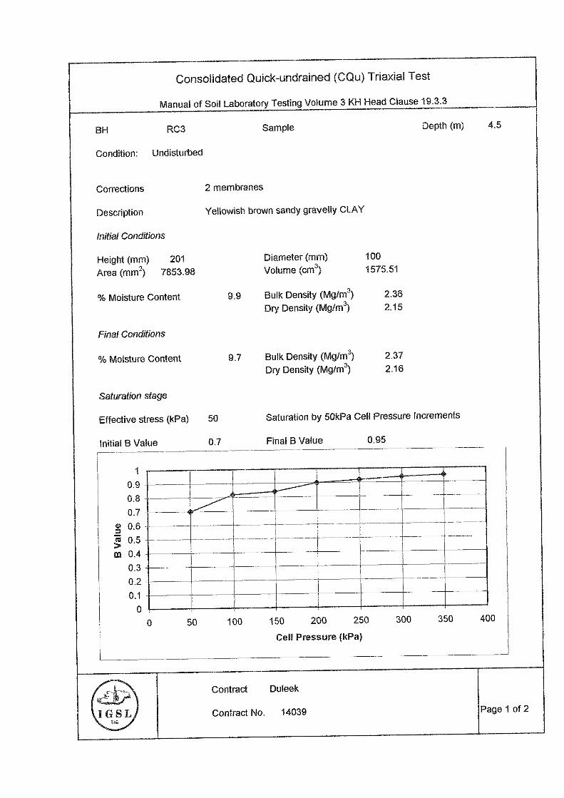
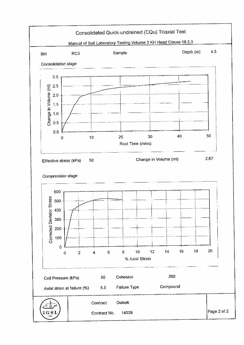
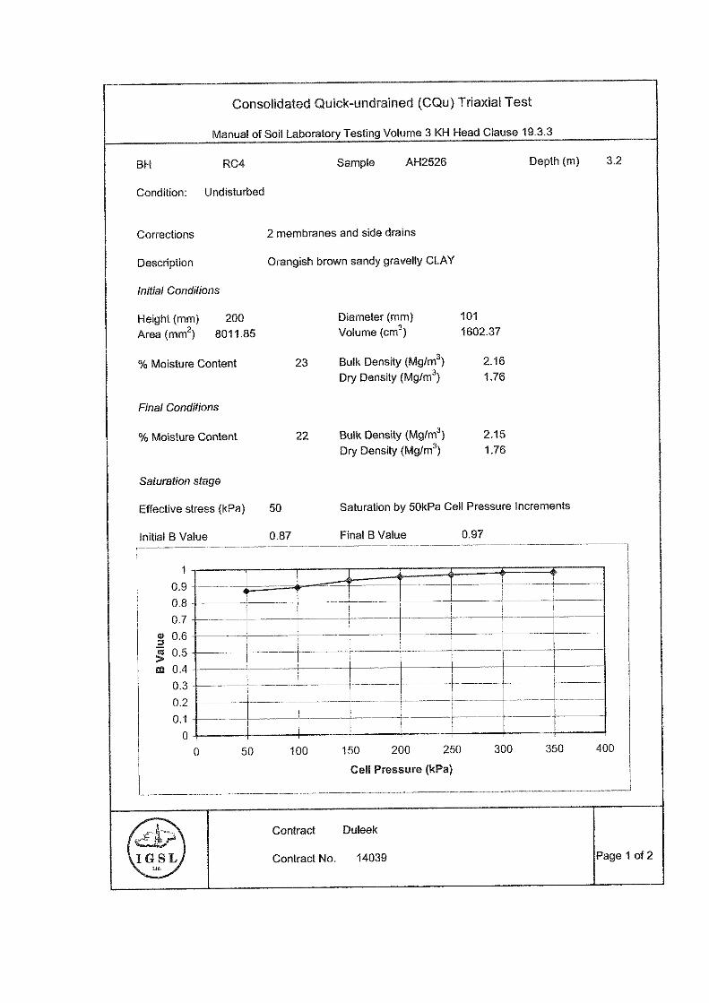
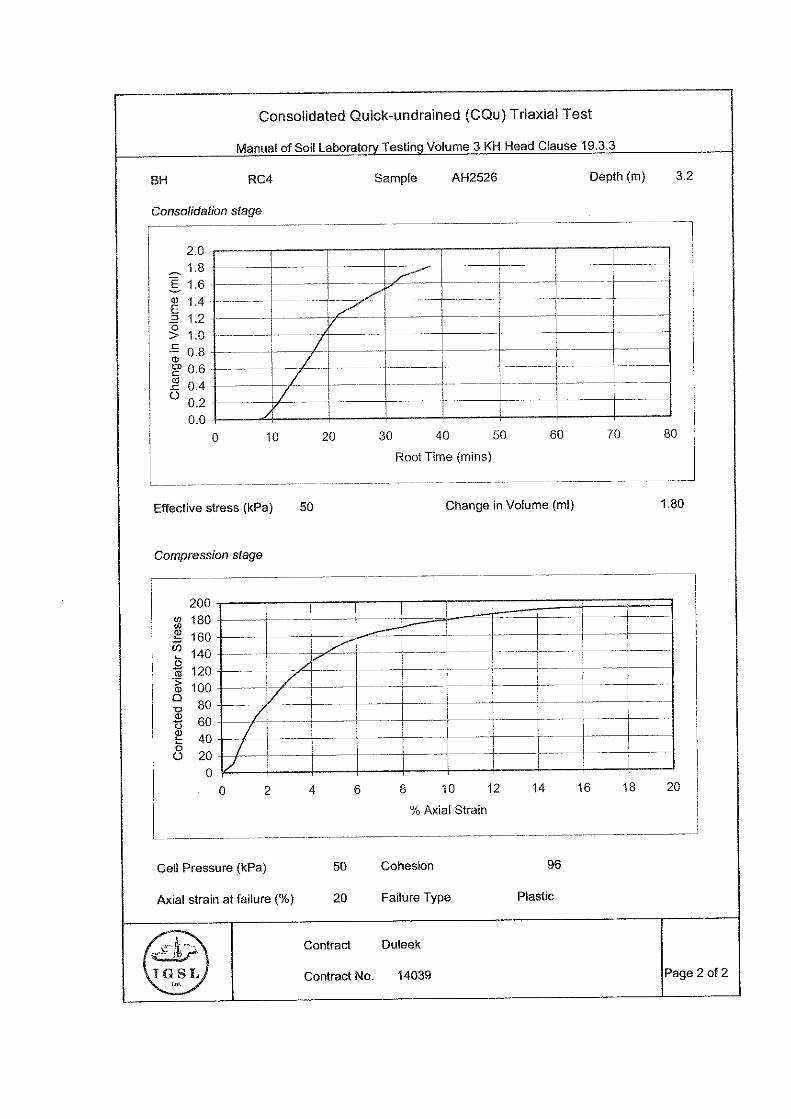
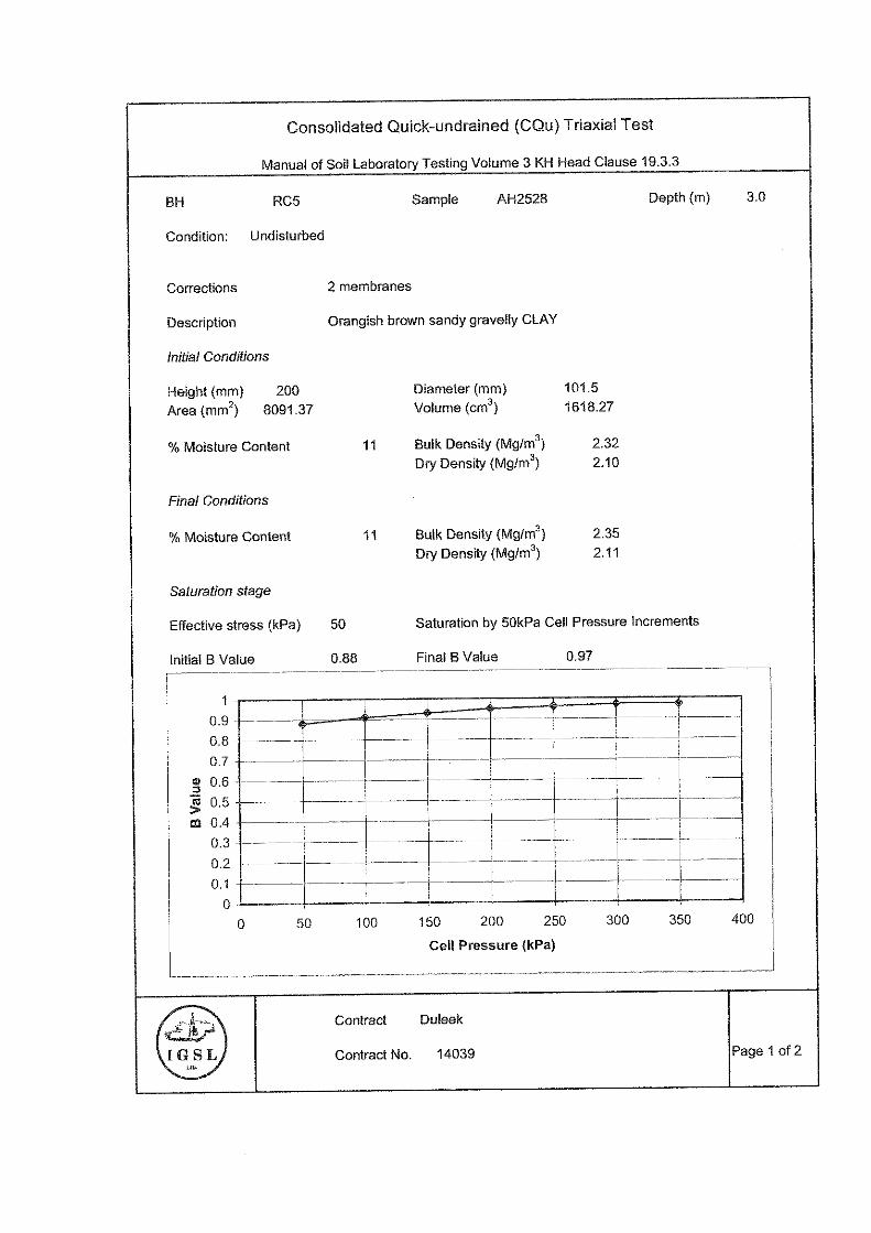
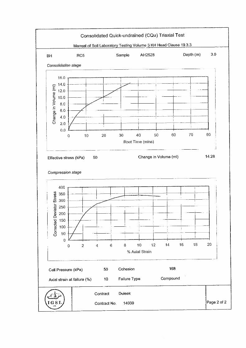
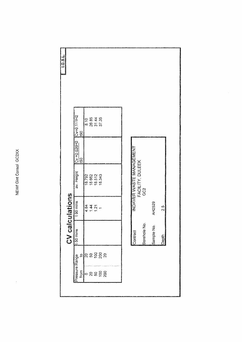
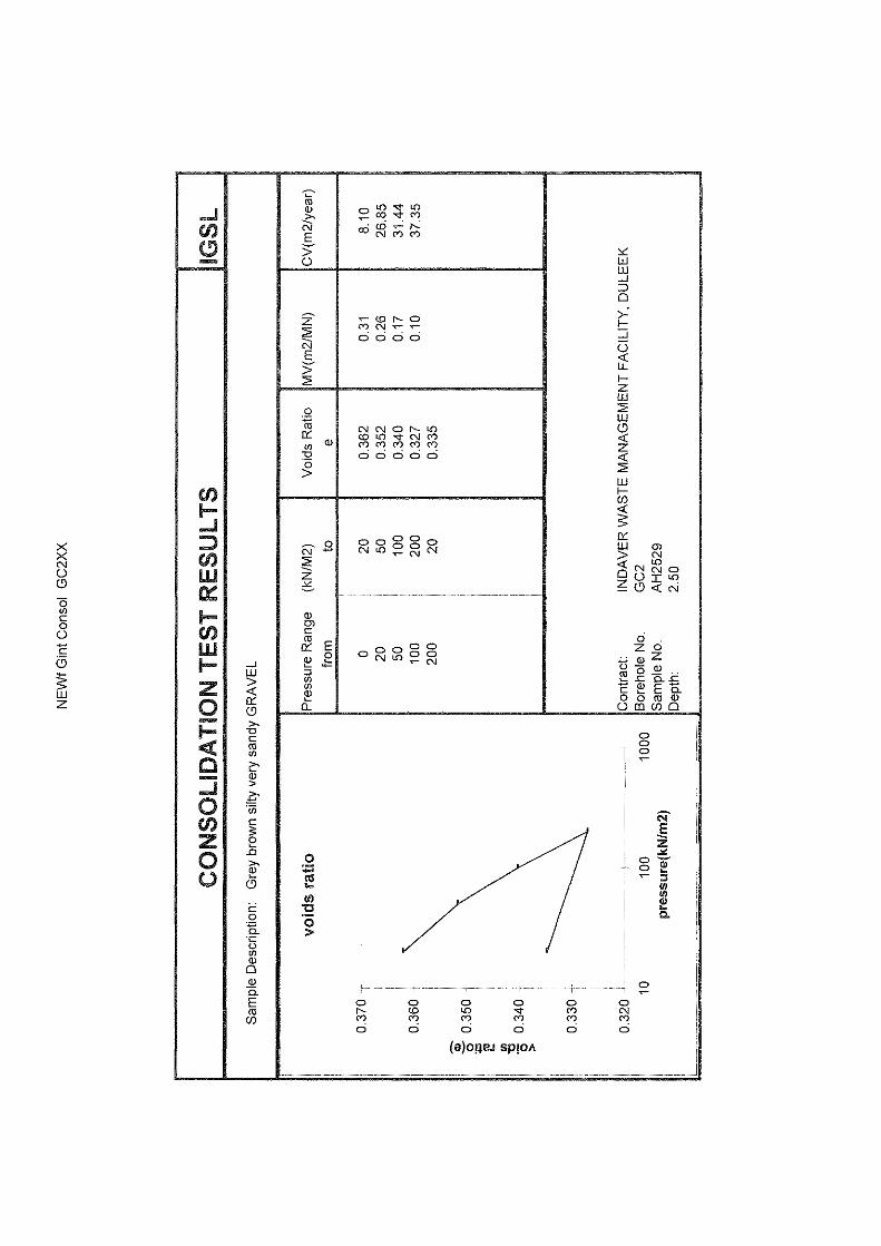
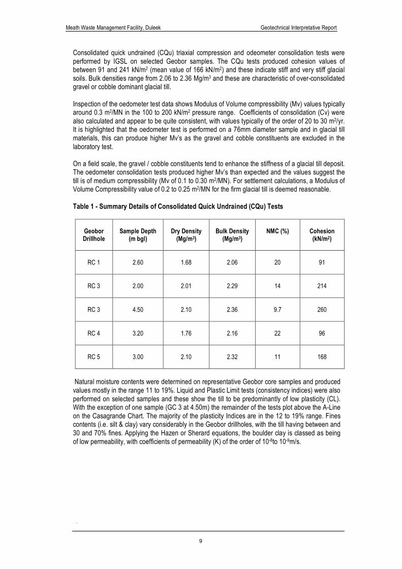
Consolidated quick undrained (CQu) triaxial compression and odeometer consolidation tests were performed by IGSL on selected Geobor samples. The CQu tests produced cohesion values of between 91 and 241 kN/m2 (mean value of 166 kN/m2) and these indicate stiff and very stiff glacial soils. Bulk densities range from 2.06 to 2.36 Mg/m3 and these are characteristic of over-consolidated gravel or cobble dominant glacial till. Inspection of the oedometer test data shows Modulus of Volume compressibility (Mv) values typically around 0.3 m2/MN in the 100 to 200 kN/m2 pressure range. Coefficients of consolidation (Cv) were also calculated and appear to be quite consistent, with values typically of the order of 20 to 30 m2/yr. It is highlighted that the oedometer test is performed on a 76mm diameter sample and in glacial till materials, this can produce higher Mv’s as the gravel and cobble constituents are excluded in the laboratory test. On a field scale, the gravel / cobble constituents tend to enhance the stiffness of a glacial till deposit. The oedometer consolidation tests produced higher Mv’s than expected and the values suggest the till is of medium compressibility (Mv of 0.1 to 0.30 m2/MN). For settlement calculations, a Modulus of Volume Compressibility value of 0.2 to 0.25 m2/MN for the firm glacial till is deemed reasonable. Table 1 - Summary Details of Consolidated Quick Undrained (CQu) Tests
Geobor Drillhole
Sample Depth
(m bgl)
Dry Density
(Mg/m3)
Bulk Density
(Mg/m3)
NMC (%)
Cohesion (kN/m2)
RC 1
2.60
1.68
2.06
20
91
RC 3
2.00
2.01
2.29
14
214
RC 3
4.50
2.10
2.36
9.7
260
RC 4
3.20
1.76
2.16
22
96
RC 5
3.00
2.10
2.32
11
168
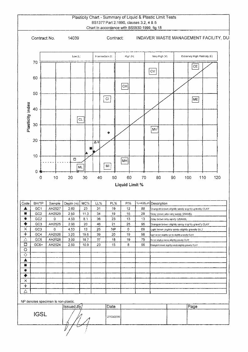
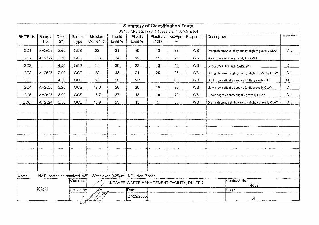
Natural moisture contents were determined on representative Geobor core samples and produced values mostly in the range 11 to 19%. Liquid and Plastic Limit tests (consistency indices) were also performed on selected samples and these show the till to be predominantly of low plasticity (CL). With the exception of one sample (GC 3 at 4.50m) the remainder of the tests plot above the A-Line on the Casagrande Chart. The majority of the plasticity Indices are in the 12 to 19% range. Fines contents (i.e. silt & clay) vary considerably in the Geobor drillholes, with the till having between and 30 and 70% fines. Applying the Hazen or Sherard equations, the boulder clay is classed as being of low permeability, with coefficients of permeability (K) of the order of 10-8to 10-9m/s.
Meath Waste Management Facility, Duleek Geotechnical Interpretative Report
10
Figure 2 - SPT Data Plot
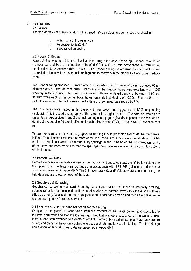
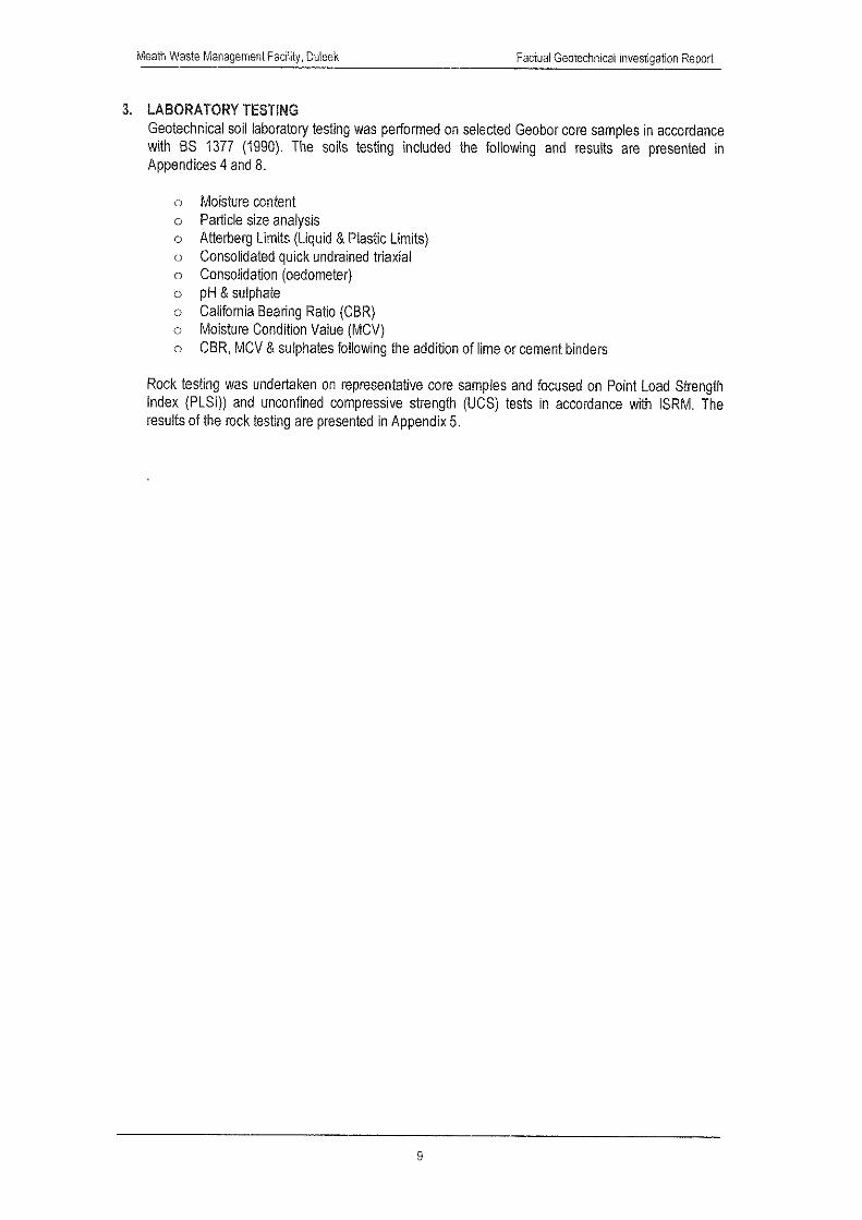
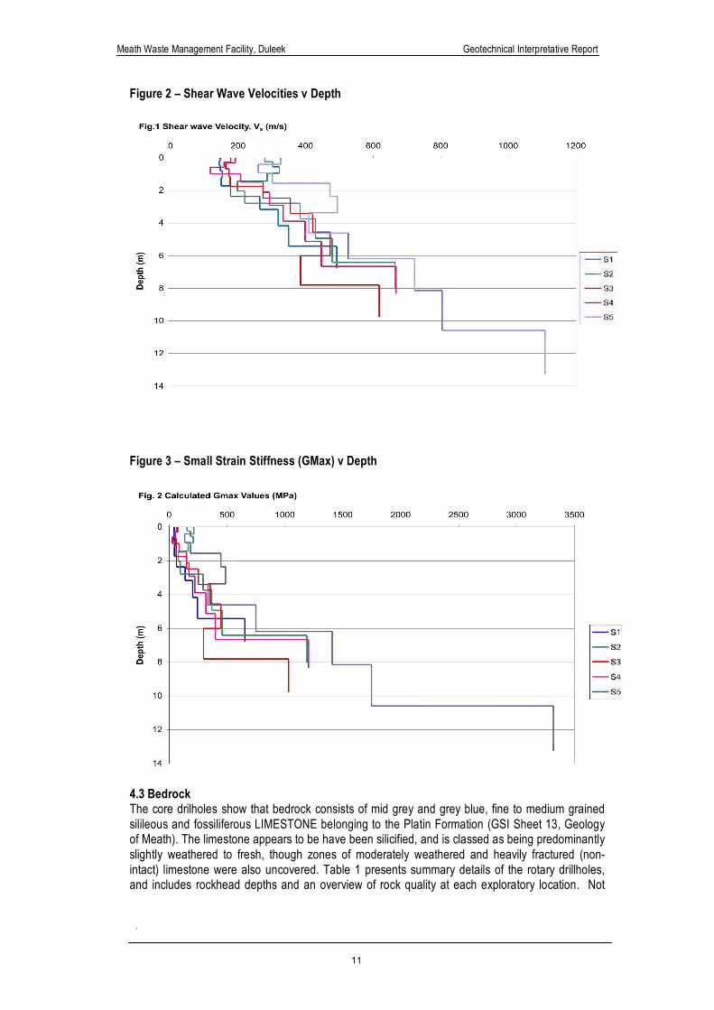
Surface wave velocities (Rayleigh waves) were measured by Apex Geoservices at five spread locations using an array of geophones at designated spacings. The shear wave velocity data (Vs) was used to derive small strain shear modulus or stiffness values (Gmax) with depth. The shear wave velocity and small strain stiffness plots have been combined and are presented in Figures 2 and 3 respectively. The shear wave velocities increase with depth and this data can be used to derive Bulk Modulus, Youngs Modulus, Poisson’s Ratio and Gmax. Values of dynamic moduli (Gmax) are typically an order of magnitude greater than static values, established by routine in-situ testing. Ground strains are generally accepted to be < 0.1% and therefore small strain stiffness values can be used to make reasonable predictions of deformations (Jardine et al. 1986). The Apex geophysical report presents values of Vs, Vp, Density, Poissons Ratio, Youngs Modulus (dynamic & static)) and Bulk Modulus. The data shows of GMax values in the upper glacial soils typically ranging from around 50 MPa to 150 MPa (firm / stiff boulder clay), increasing to 500 MPa in the very stiff till /upper variably weathered bedrock. The variations in the small strain stiffness values correlate well with the variations in soil composition as indicated by the Geobor core recovery. There is a noticeable ‘kick’ at a depth of approximately 5 to 6m, this correlates with the core drillhole data (GC 1 to 5) where rockhead was confirmed at depths of 5.30 to 8.00m.
Meath Waste Management Facility, Duleek Geotechnical Interpretative Report
11
Figure 2 – Shear Wave Velocities v Depth
Figure 3 – Small Strain Stiffness (GMax) v Depth
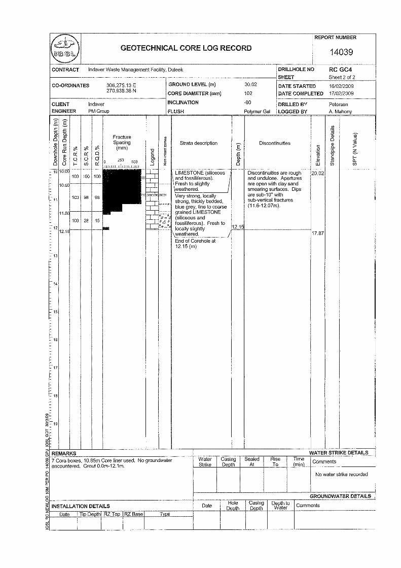
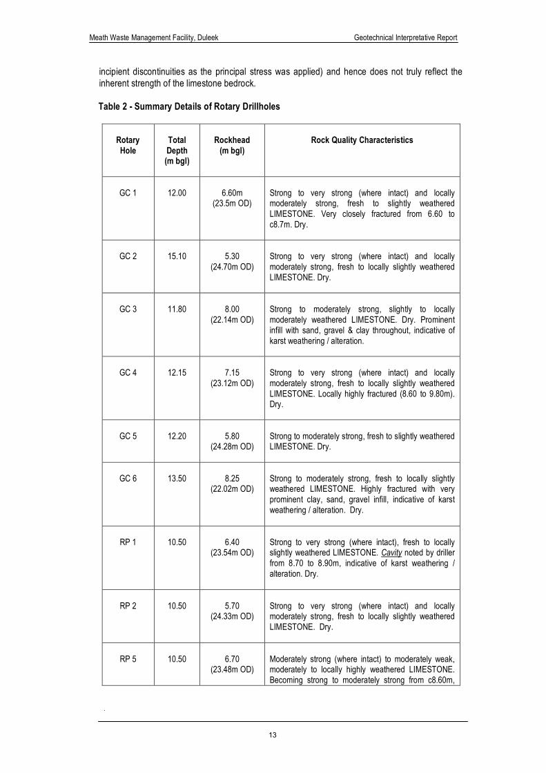
4.3 Bedrock The core drilholes show that bedrock consists of mid grey and grey blue, fine to medium grained silileous and fossiliferous LIMESTONE belonging to the Platin Formation (GSI Sheet 13, Geology of Meath). The limestone appears to be have been silicified, and is classed as being predominantly slightly weathered to fresh, though zones of moderately weathered and heavily fractured (non-intact) limestone were also uncovered. Table 1 presents summary details of the rotary drillholes, and includes rockhead depths and an overview of rock quality at each exploratory location. Not
Meath Waste Management Facility, Duleek Geotechnical Interpretative Report
12
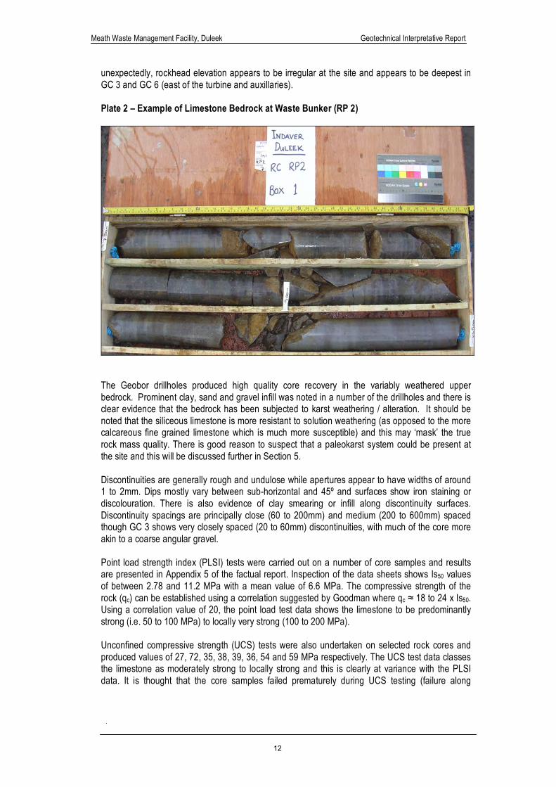
unexpectedly, rockhead elevation appears to be irregular at the site and appears to be deepest in GC 3 and GC 6 (east of the turbine and auxillaries). Plate 2 – Example of Limestone Bedrock at Waste Bunker (RP 2)
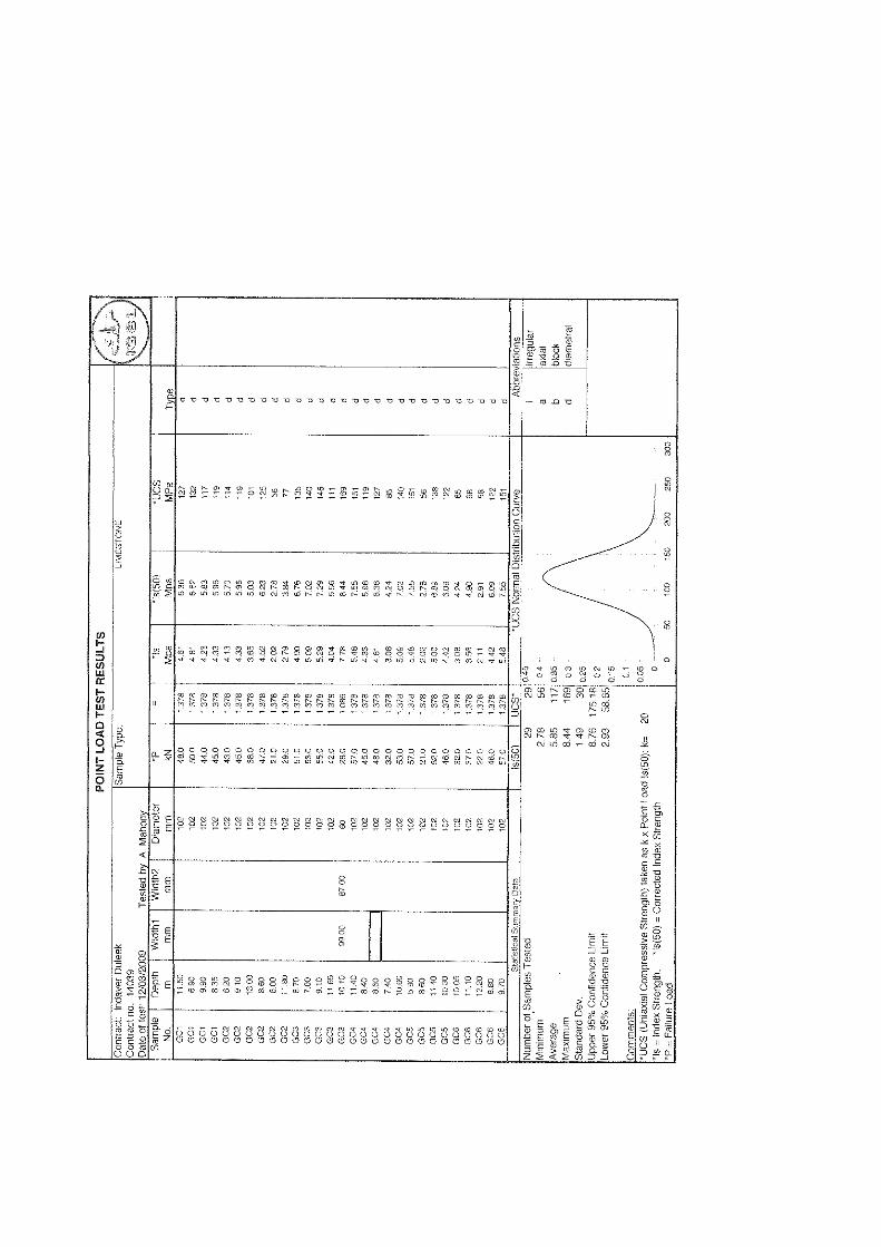
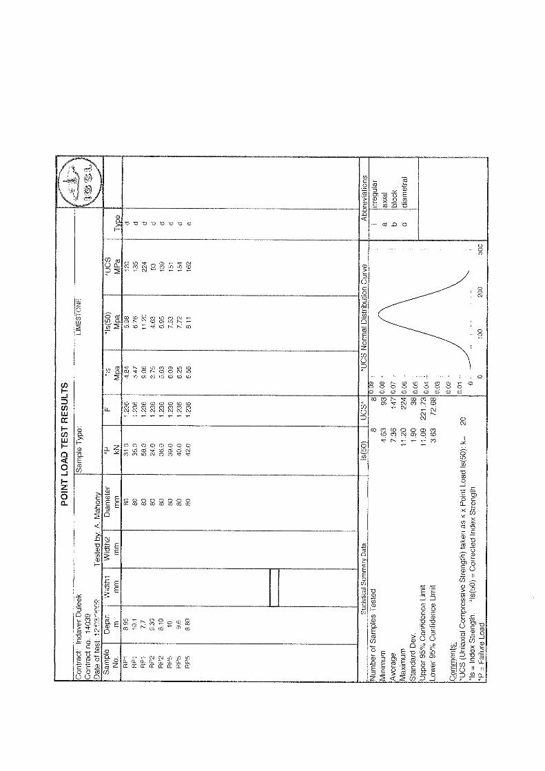
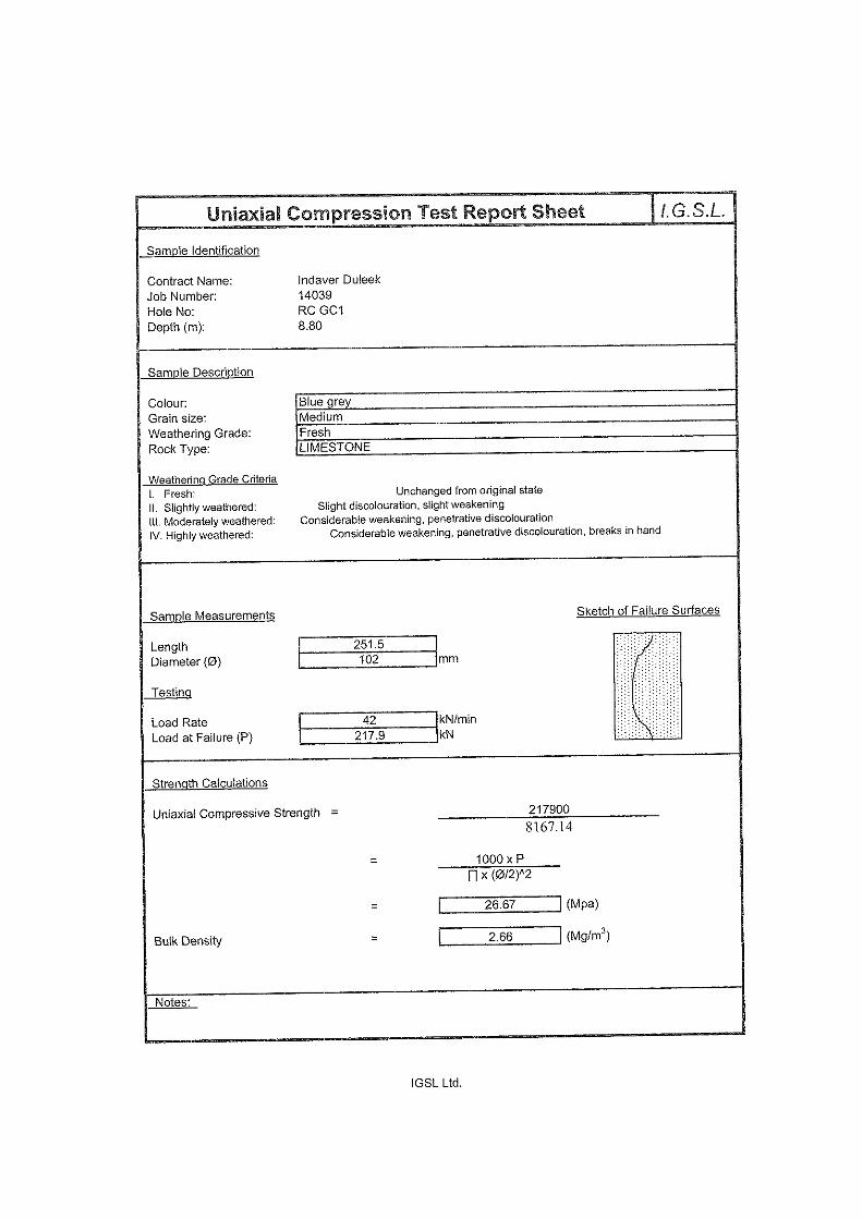
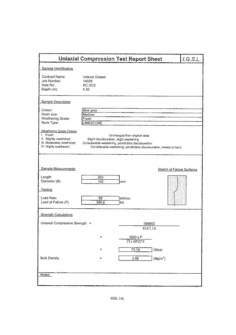
The Geobor drillholes produced high quality core recovery in the variably weathered upper bedrock. Prominent clay, sand and gravel infill was noted in a number of the drillholes and there is clear evidence that the bedrock has been subjected to karst weathering / alteration. It should be noted that the siliceous limestone is more resistant to solution weathering (as opposed to the more calcareous fine grained limestone which is much more susceptible) and this may ‘mask’ the true rock mass quality. There is good reason to suspect that a paleokarst system could be present at the site and this will be discussed further in Section 5. Discontinuities are generally rough and undulose while apertures appear to have widths of around 1 to 2mm. Dips mostly vary between sub-horizontal and 45º and surfaces show iron staining or discolouration. There is also evidence of clay smearing or infill along discontinuity surfaces. Discontinuity spacings are principally close (60 to 200mm) and medium (200 to 600mm) spaced though GC 3 shows very closely spaced (20 to 60mm) discontinuities, with much of the core more akin to a coarse angular gravel. Point load strength index (PLSI) tests were carried out on a number of core samples and results are presented in Appendix 5 of the factual report. Inspection of the data sheets shows Is50 values of between 2.78 and 11.2 MPa with a mean value of 6.6 MPa. The compressive strength of the rock (qc) can be established using a correlation suggested by Goodman where qc ≈ 18 to 24 x Is50. Using a correlation value of 20, the point load test data shows the limestone to be predominantly strong (i.e. 50 to 100 MPa) to locally very strong (100 to 200 MPa). Unconfined compressive strength (UCS) tests were also undertaken on selected rock cores and produced values of 27, 72, 35, 38, 39, 36, 54 and 59 MPa respectively. The UCS test data classes the limestone as moderately strong to locally strong and this is clearly at variance with the PLSI data. It is thought that the core samples failed prematurely during UCS testing (failure along
Meath Waste Management Facility, Duleek Geotechnical Interpretative Report
13
incipient discontinuities as the principal stress was applied) and hence does not truly reflect the inherent strength of the limestone bedrock.
Table 2 - Summary Details of Rotary Drillholes
Rotary Hole
Total Depth (m bgl)
Rockhead
(m bgl)
Rock Quality Characteristics
GC 1
12.00
6.60m
(23.5m OD)
Strong to very strong (where intact) and locally moderately strong, fresh to slightly weathered LIMESTONE. Very closely fractured from 6.60 to c8.7m. Dry.
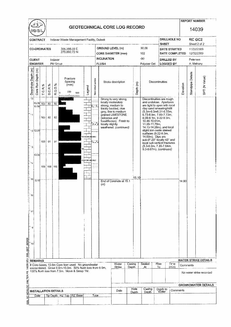
GC 2
15.10
5.30
(24.70m OD)
Strong to very strong (where intact) and locally moderately strong, fresh to locally slightly weathered LIMESTONE. Dry.
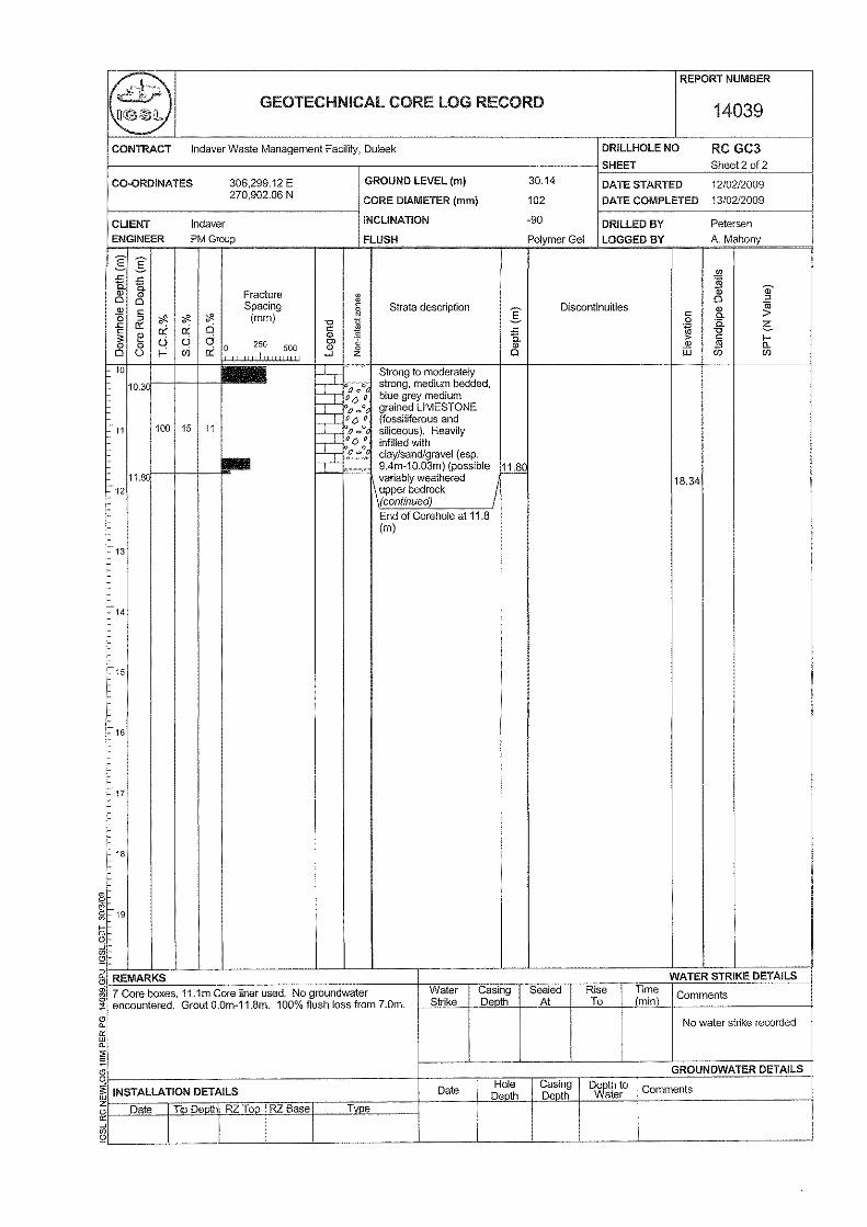
GC 3
11.80
8.00
(22.14m OD)
Strong to moderately strong, slightly to locally moderately weathered LIMESTONE. Dry. Prominent infill with sand, gravel & clay throughout, indicative of karst weathering / alteration.
GC 4
12.15
7.15
(23.12m OD)
Strong to very strong (where intact) and locally moderately strong, fresh to locally slightly weathered LIMESTONE. Locally highly fractured (8.60 to 9.80m). Dry.
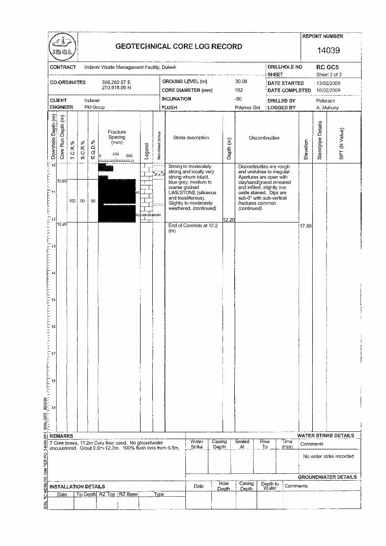
GC 5
12.20
5.80
(24.28m OD)
Strong to moderately strong, fresh to slightly weathered LIMESTONE. Dry.
GC 6
13.50
8.25
(22.02m OD)
Strong to moderately strong, fresh to locally slightly weathered LIMESTONE. Highly fractured with very prominent clay, sand, gravel infill, indicative of karst weathering / alteration. Dry.
RP 1
10.50
6.40
(23.54m OD)
Strong to very strong (where intact), fresh to locally slightly weathered LIMESTONE. Cavity noted by driller from 8.70 to 8.90m, indicative of karst weathering / alteration. Dry.
RP 2
10.50
5.70
(24.33m OD)
Strong to very strong (where intact) and locally moderately strong, fresh to locally slightly weathered LIMESTONE. Dry.
RP 5
10.50
6.70
(23.48m OD)
Moderately strong (where intact) to moderately weak, moderately to locally highly weathered LIMESTONE. Becoming strong to moderately strong from c8.60m,

Meath Waste Management Facility, Duleek Geotechnical Interpretative Report
14
upper bedrock zone highly weathered / non-intact (6.70 to c8.60m). Dry.
4.4 Groundwater
Groundwater was not encountered in any of the nine IGSL rotary core drilholes. It is highlighted that loss of water flush was observed during drilling and this is characteristic of karst bedrock. It is noted that standpipes were not installed in the rotary drillholes to establish equilibrium groundwater levels.
Meath Waste Management Facility, Duleek Geotechnical Interpretative Report
15
5. DISCUSSION & RECOMMENDATIONS 5.1 General It is understood that a waste to energy facility will be constructed at this site. In light of this and the geotechnical / geophysical findings, the following ground engineering issues are developed and discussed:
• Bearing capacity • Foundations & floor slabs
• Excavatability
• Earthworks & modification of glacial soils
• Groundwater
• Slopes & ground retention
• Karst weathering & geotechnical risk management
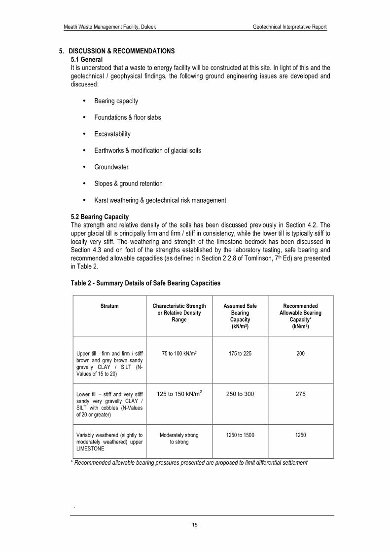
5.2 Bearing Capacity The strength and relative density of the soils has been discussed previously in Section 4.2. The upper glacial till is principally firm and firm / stiff in consistency, while the lower till is typically stiff to locally very stiff. The weathering and strength of the limestone bedrock has been discussed in Section 4.3 and on foot of the strengths established by the laboratory testing, safe bearing and recommended allowable capacities (as defined in Section 2.2.8 of Tomlinson, 7th Ed) are presented in Table 2.
Table 2 - Summary Details of Safe Bearing Capacities
Stratum
Characteristic Strength or Relative Density
Range
Assumed Safe
Bearing Capacity (kN/m2)
Recommended
Allowable Bearing Capacity* (kN/m2)
Upper till - firm and firm / stiff brown and grey brown sandy gravelly CLAY / SILT (N-Values of 15 to 20)
75 to 100 kN/m2
175 to 225
200
Lower till – stiff and very stiff sandy very gravelly CLAY / SILT with cobbles (N-Values of 20 or greater)
125 to 150 kN/m2
250 to 300
275
Variably weathered (slightly to moderately weathered) upper LIMESTONE
Moderately strong
to strong
1250 to 1500
1250
* Recommended allowable bearing pressures presented are proposed to limit differential settlement
Meath Waste Management Facility, Duleek Geotechnical Interpretative Report
16
The upper glacial till is typically firm / stiff and should provide an allowable bearing capacity of 200 kN/m2. The Geobor cores and associated laboratory testing indicates the lower till to be stiff / very stiff and this should safely support loads of the order of 250 kN/m2. It is highlighted that the low plasticity glacial till will be particularly susceptible or sensitive to small increases in moisture content and should be protected without delay to avoid degradation. An allowable bearing capacity of 1250 kN/m2 is suggested for pad or spread foundations located on the upper variably weathered limestone bedrock. Should foundations be located on the slightly weathered / fresh strong or very strong limestone, then an allowable bearing capacity of 1750 to 2000 kN/m2 could be adopted.
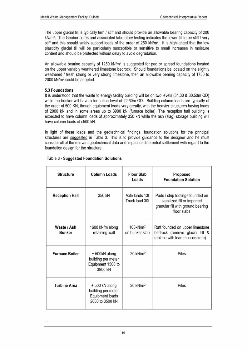
5.3 Foundations It is understood that the waste to energy facility building will be on two levels (34.00 & 30.50m OD) while the bunker will have a formation level of 22.60m OD. Building column loads are typically of the order of 500 KN, though equipment loads vary greatly, with the heavier structures having loads of 2000 kN and in some areas up to 3900 kN (furnace boiler). The reception hall building is expected to have column loads of approximately 350 kN while the ash (slag) storage building will have column loads of c500 kN. In light of these loads and the geotechnical findings, foundation solutions for the principal structures are suggested in Table 3. This is to provide guidance to the designer and he must consider all of the relevant geotechnical data and impact of differential settlement with regard to the foundation design for the structure.
Table 3 - Suggested Foundation Solutions
Structure
Column Loads
Floor Slab
Loads
Proposed
Foundation Solution
Reception Hall
350 kN
Axle loads 13t Truck load 30t
Pads / strip footings founded on
stabilized fill or imported granular fill with ground bearing
floor slabs
Waste / Ash
Bunker
1600 kN/m along
retaining wall
100kN/m2
on bunker slab
Raft founded on upper limestone bedrock (remove glacial till & replace with lean mix concrete)
Furnace Boiler
+ 500kN along
building perimeter Equipment 1500 to
3900 kN
20 kN/m2
Piles
Turbine Area
+ 500 kN along
building perimeter Equipment loads 2000 to 3500 kN
20 kN/m2
Piles
Meath Waste Management Facility, Duleek Geotechnical Interpretative Report
17
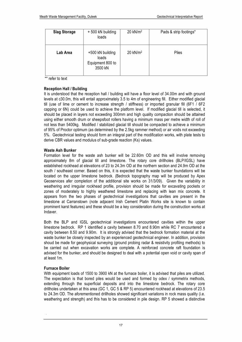
Slag Storage + 500 kN building loads
20 kN/m2
Pads & strip footings*
Lab Area
+500 kN building
loads Equipment 800 to
3500 kN
20 kN/m2
Piles
** refer to text
Reception Hall / Building It is understood that the reception hall / building will have a floor level of 34.00m and with ground levels at c30.0m, this will entail approximately 3.5 to 4m of engineering fill. Either modified glacial till (use of lime or cement to increase strength / stiffness) or imported granular fill (6F1 / 6F2 capping or 6N) could be used to achieve the platform level. If modified glacial till is selected, it should be placed in layers not exceeding 300mm and high quality compaction should be attained using either smooth drum or sheepsfoot rollers having a minimum mass per metre width of roll of not less than 5400kg. Modified / stabilized glacial till should be compacted to achieve a minimum of 95% of Proctor optimum (as determined by the 2.5kg rammer method) or air voids not exceeding 5%. Geotechnical testing should form an integral part of the modification works, with plate tests to derive CBR values and modulus of sub-grade reaction (Ks) values. Waste Ash Bunker Formation level for the waste ash bunker will be 22.60m OD and this will involve removing approximately 8m of glacial till and limestone. The rotary core drillholes (BLP/IGSL) have established rockhead at elevations of 23 to 24.3m OD at the northern section and 24.9m OD at the south / southeast corner. Based on this, it is expected that the waste bunker foundations will be located on the upper limestone bedrock. (Bedrock topography map will be produced by Apex Geoservices afer completion of the additional site works on 31/3/09). Given the variability in weathering and irregular rockhead profile, provision should be made for excavating pockets or zones of moderately to highly weathered limestone and replacing with lean mix concrete. It appears from the two phases of geotechnical investigations that cavities are present in the limestone at Carranstown (note adjacent Irish Cement Platin Works site is known to contain prominent karst features) and these should be a key consideration during the construction works at Indaver. Both the BLP and IGSL geotechnical investigations encountered cavities within the upper limestone bedrock. RP 1 identified a cavity between 8.70 and 8.90m while RC 7 encountered a cavity between 8.50 and 9.90m. It is strongly advised that the bedrock formation material at the waste bunker be closely inspected by an experienced geotechnical engineer. In addition, provision shoud be made for geophysical surveying (ground probing radar & resistivity profiling methods) to be carried out when excavation works are complete. A reinforced concrete raft foundation is advised for the bunker, and should be designed to deal with a potential open void or cavity span of at least 1m. Furnace Boiler With equipment loads of 1500 to 3900 kN at the furnace boiler, it is advised that piles are utilized. The expectation is that bored piles would be used and formed by odex / symmetrix methods, extending through the superficial deposits and into the limestone bedrock. The rotary core drillholes undertaken at this area (GC 1, GC 5 & RP 5) encountered rockhead at elevations of 23.5 to 24.3m OD. The aforementioned drillholes showed significant variations in rock mass quality (i.e. weathering and strength) and this has to be considered in pile design. RP 5 showed a distinctive
Meath Waste Management Facility, Duleek Geotechnical Interpretative Report
18
highly weathered profile from 23.5 to 21.5m OD. On the evidence of the rotary holes (particularly RP 5) pile lengths are expected to vary considerably, with load capacity dependant on variation in strengths and alteration due to karst weathering. For preliminary foundation design purposes, it would be reasonable to assume that 600mm diameter piles, founded in the limestone bedrock, would provide a safe working load of the order of 1500kN. Therefore, pile groups of 3 or 4 could be designed to accommodate equipment loads of 4000 to 5000 kN. The piles should achieve adequate socket depths and rely largely on skin friction developed within the glacial till and limestone bedrock. If end bearing is to be relied upon, then core drilling should be carried out to validate rock quality below the pile toe. In view of the variably weathered nature of the karst altered limestone bedrock, the emphasis should be on reducing pile capacity and ensuring that the pile group can safely accommodate the column loads. It is expected that bored piles would have a minimum socket depth of 2.5 to 3m but this will be governed by the actual weathering profile and degree of intactness of the limestone bedrock at each pile group location. Turbine Area The ground conditions at the turbine area comprise stiff glacial till underlain by strong and very strong limestone bedrock (at an elevation of approximately 21.3m OD based on RC 2 BLP/GII Report). Again, equipment loads are considerable at the turbine area (up to 3500 kN), hence piles are recommended. It is expected that the piles for this structure will extend into the limestone bedrock (to provide an adequate socket). There was no evidence of cavities or voids in RC 2 and total core recovery (TCR) was fair to good. The limestone appears to be largely intact (though non-intact zone was present from 19 to 18.2m OD) and should provide a competent founding medium. Again, 600 or 900mm diameter bored piles are expected to be used and extend sufficiently into the intact or competent limestone. Slag Storage Building Building column loads at the slag storage building are estimated at +500 kN. GC 1 and GC 4 are most relevant to this area (note an absence of geotechnical information at the northern portion) and showed the glacial till materials to be generally stiff or upperbound medium dense. It is expected that pad and strip footing foundations will be utilized at this area and should be sized using an allowable bearing capacity of 200 kN/m2. The real concern with utilizing pads at this building is the potential for differential settlement and the impact this would have on the structure. In karst altered terrain, the strength / stiffness of glacial till soils can be highly variable (due to migration into voided zones) and this should be considered. Before foundations are finalized for the slag storage building, a programme of dynamic probing should be considered (grid of 5 x 5m) to evaluate the strength of the upper soils (i.e. within 3 to 4m of existing ground level). This data should be subsequently reviewed with the small strain stiffness geophysical data (Gmax profiles).
5.4 Floor Slabs Anticipated floor slab loadings are presented in Table 2 and are generally of the order of 20 kN/m2. Ground bearing floor slabs are expected to be suitable for the reception hall, slag storage, administration and laboratory buildings. Ground bearing floor slabs should not be located on made ground / fill material. This is due to its inherent variability and likely poor compaction (or no compaction), hence total and differential settlement would be a real concern. Made ground / fill materials should be removed and replaced with suitable approved engineering fill (i.e. imported granular fill or stabilized glacial till). Given the silt dominant nature of the glacial till and proposed floor slabs loadings of 20 kN/m2 a minimum granular layer thickness (6F1 / 6F2) of 500 mm is recommended. However, where floor slab loading are > 20 kN/m2 an enhanced modulus granular layer should be considered. A granular
Meath Waste Management Facility, Duleek Geotechnical Interpretative Report
19
layer thickness of 600 to 800mm should be considered where modulus of sub-grade reaction values (Ks) are < 20 MPa/m or CBR < 1%. If imported limestone / mudstone derived granular fill is used under floor slabs or structures, then it should have a minimum Ten Per Cent Fines Value of 130 kN and minimum CBR value of 15% (derived using plate bearing plate method). From a chemical and pyrite degradation aspect, granular fill material should have a maximum equivalent pyrite content of < 1% (i.e. low to medium swelling potential in accordance with CTQ-M200), maximum total sulphur content of 1.0% (or < 0.4% if pyrrhotite is suspected) and maximum acid soluble sulphate of 0.2% in accordance with IS EN 13242:2002. If pyrite is present in granular fill, this may lead to problems with oxidation, weathering and adverse reaction with carbonate minerals. Potentially expansive fill materials should not be used under structures. Imported granular fill material (e.g. capping or sub-base) should be thoroughly checked for total sulphur and soluble sulphates (SO4). Thin section petrographic analysis should also be carried out to determine mineralogical composition, particularly for the presence of pyrite in the rock matrix (especially more reactive fine grained or framboidal pyrite). 5.5 Excavatability The key factors which govern or control excavation methods in glacial till / boulder clay and hence production rates are the strength of the matrix and frequency or predominance of boulders. On the basis of the SPT Values and strength descriptors on the logs, excavation of the glacial till is expected to be efficiently carried out using 20t tracked excavators. The three key factors, which govern or control excavation methods and hence production rates in bedrock are:
• compressive strength of the rock
• discontinuity / bed spacings
• orientation and tightness of the discontinuities or bedding
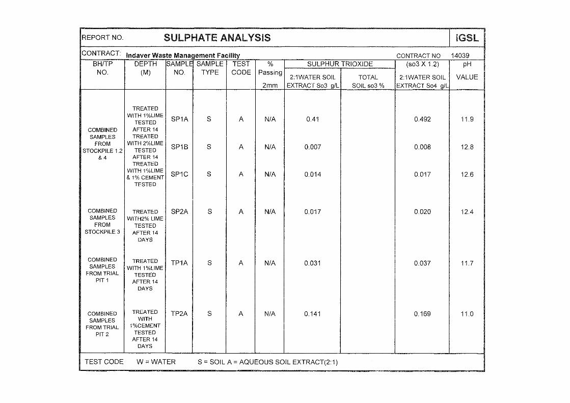
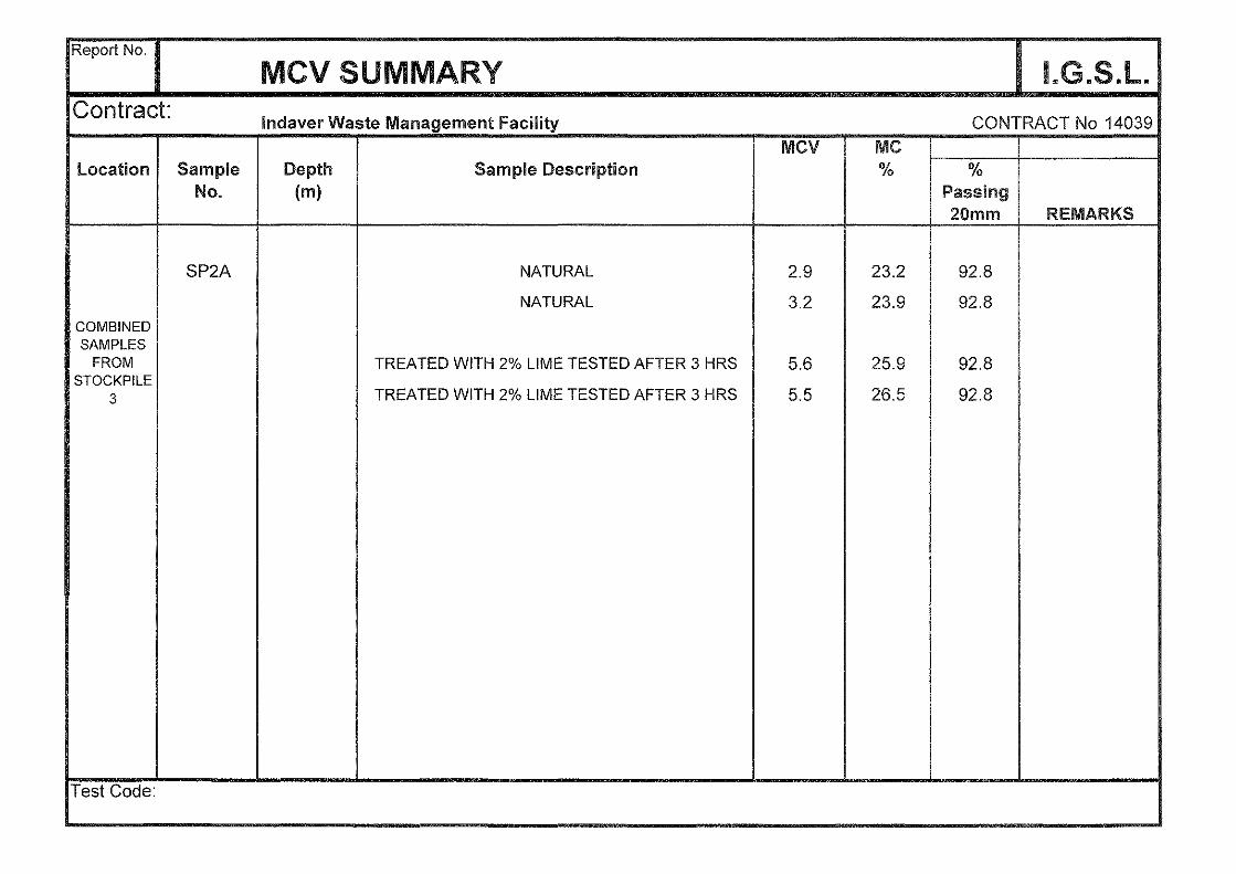
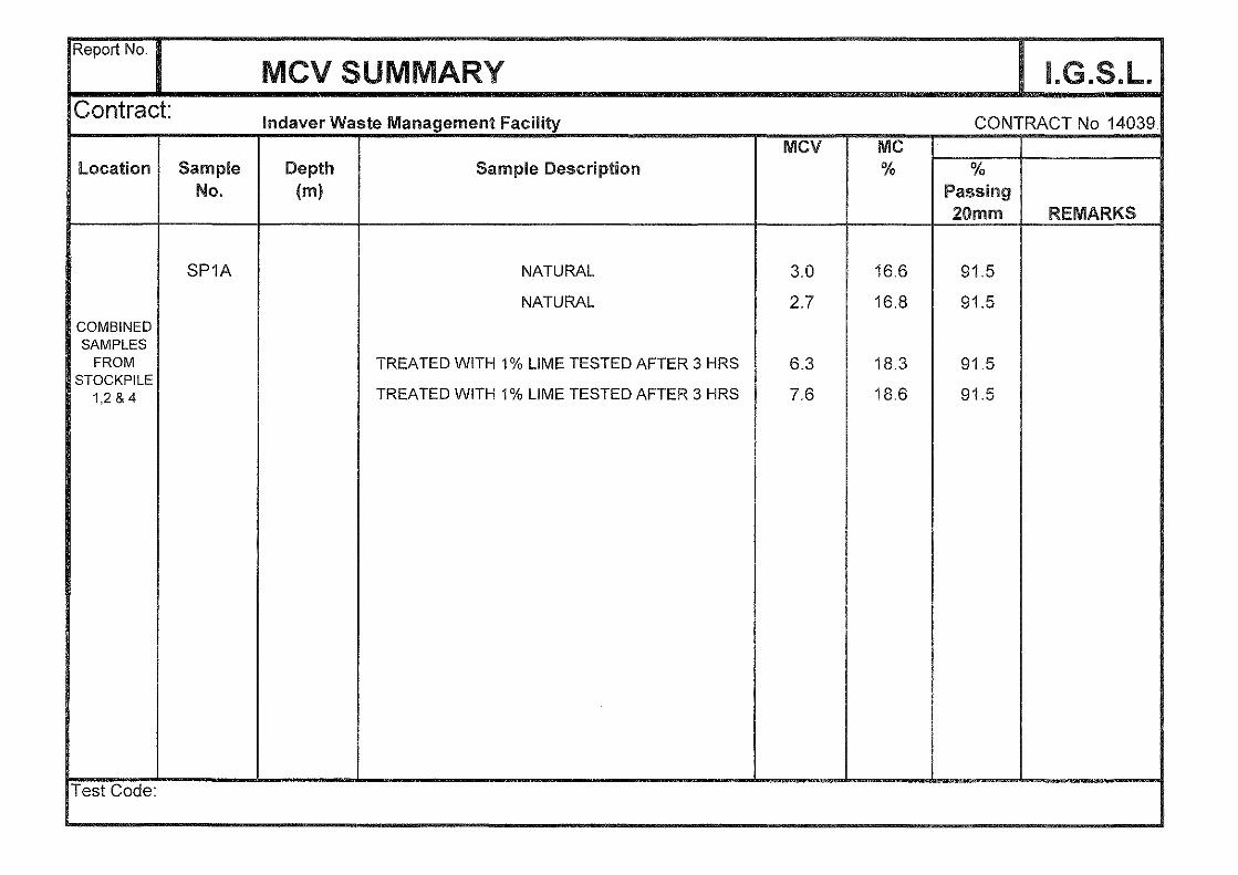
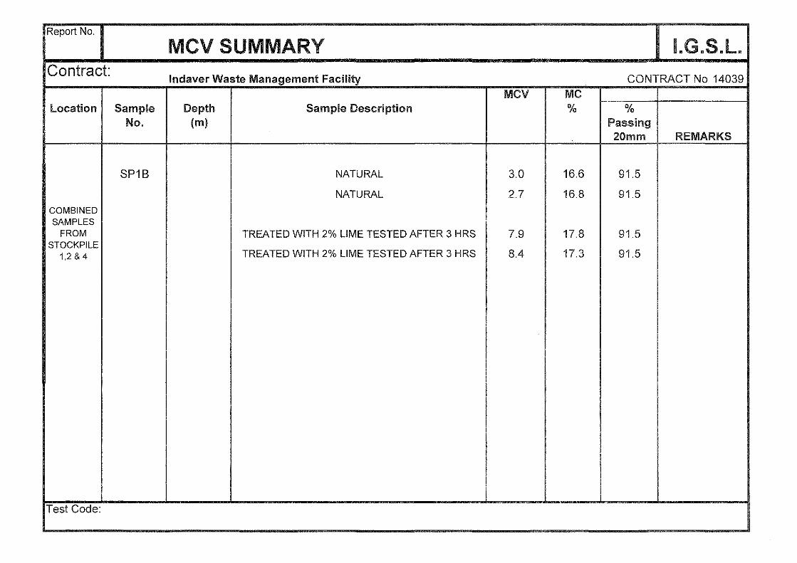
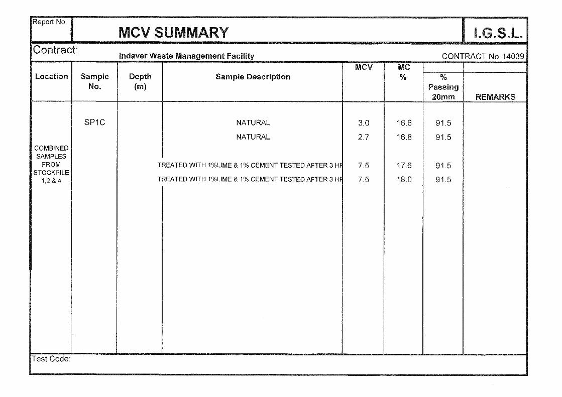
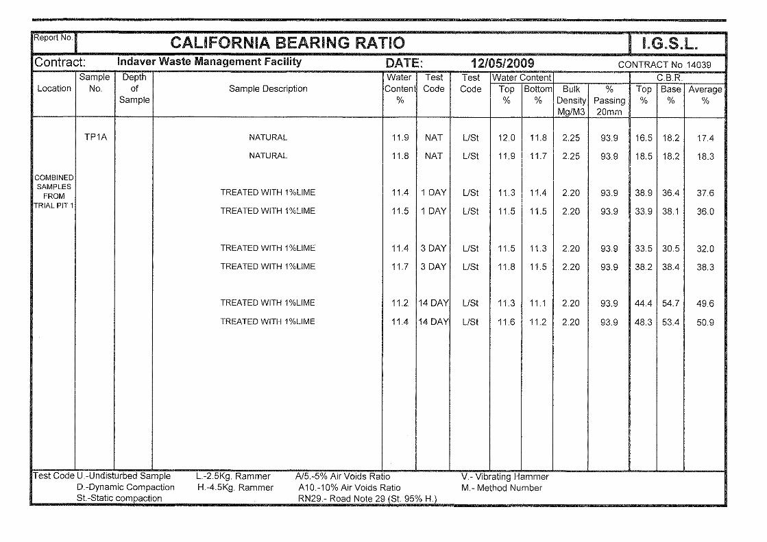
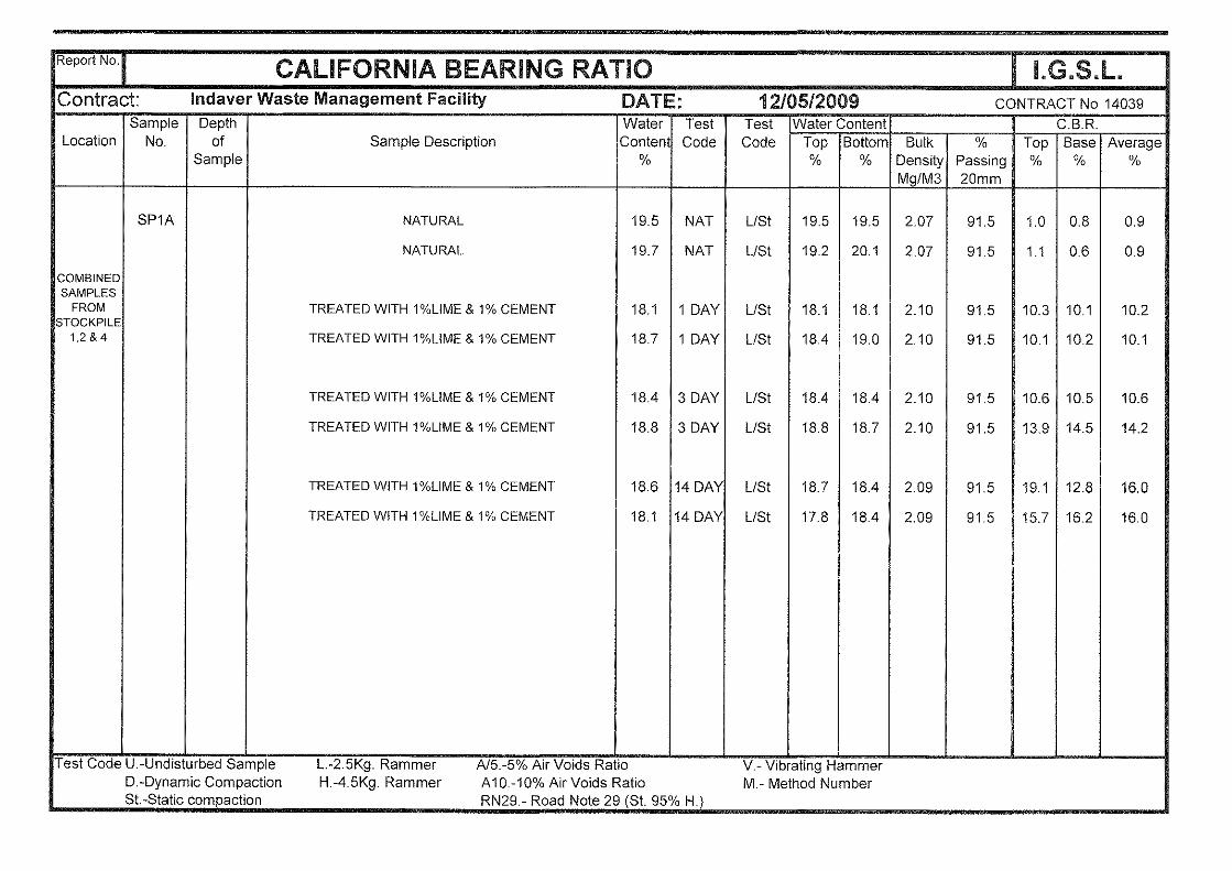
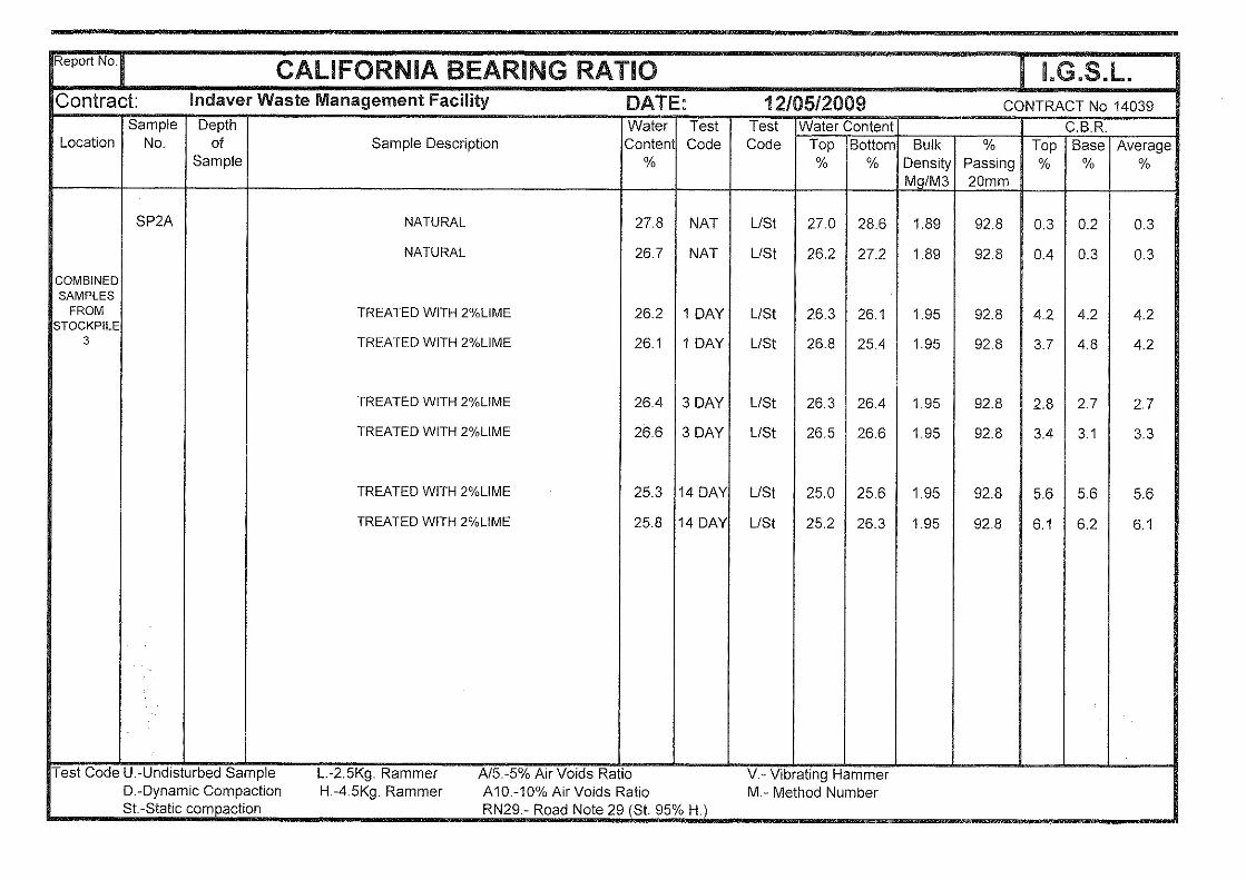
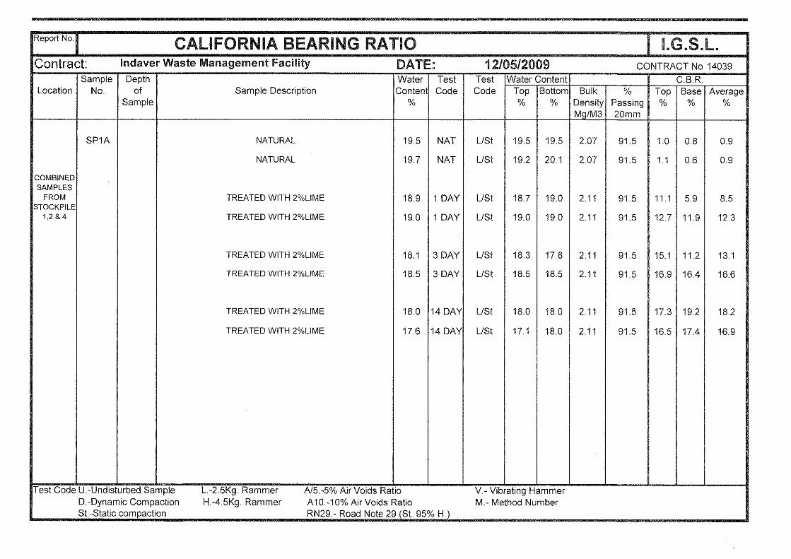
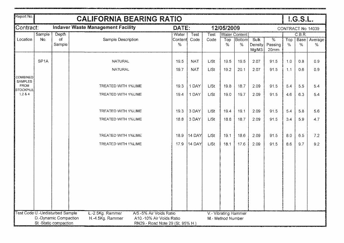
A number of methods are available to assess the excavatability characteristics of the limestone bedrock, including the Pettifer & Fookes chart, Weaver rating chart etc. On the basis of the mechanical indices (SCR/RQD), discontinuity characteristics and strengths established by the point load tests, heavy digging and hydraulic breaking (6 or 8t breakers mounted on 50t excavators) is anticipated to efficiently loosen or fracture the upper bedrock. The strong / very strong siliceous or fossiliferous limestone bedrock will be more onerous to loosen and this should be considered by civil engineering contractors. Trench excavations in the strong / very strong limestone bedrock will be very onerous (due to the lack of a free face) and the siliceous limestone will tend to reduce to a powder. It is highlighted that the Pettifer & Fookes excavatability chart (nomogram) tends to be very optimistic for indurated Irish bedrock deposits, particularly strong / very strong materials. It provides no information on production rates and serves only as a guide in assessing possible excavation methods digging/ripping/hydraulic breaking/blasting). 5.6 Earthworks & Modification of Glacial Soils In view of the variability of the glacial till soils and concerns regarding their re-use potential, a programme of laboratory modification / stabilization testing was carried out by IGSL. Moisture Condition Value (MCV) and California Bearing Ratio (CBR) tests were undertaken on samples of the glacial till recovered from the bunker footprint and stockpiles constructed by Sisk. This focused on two modes of testing following the addition of calcium oxide (supplied by White Rhino, Clogrennane) or OPC to the glacial till. MCV’s were carried out after a period of circa 3 hours and
Meath Waste Management Facility, Duleek Geotechnical Interpretative Report
20
CBR tests following curing for periods of 1, 3 and 14 days respectively. The CBR and MCV tests were performed on unsoaked samples, where the material was allowed to cure at a laboratory temperature of 16 to 18°C. Inspection of the laboratory test data in the factual report shows MCV’s increased significantly after lime or cement binder was added. The MCV’s were undertaken after mixing and curing for 3 hours. In the majority of cases, the MCV’s increased to +7 with the material from the bunker footprint (TP 1A & 1B) performing best. The samples from the stockpiles were considerably wetter and the MCV’s on these samples increased modestly after adding 1 or 2% calcium oxide. With regard to the CBR test data, the glacial till material showed a good exothermic reaction with calcium oxide, particularly the samples from the bunker (TP 1A & 1B), which produced high CBR values. The CBR values from the stockpile samples were considerably lower and more erratic, even with 2% binder. It is concluded from the modification / stabilization laboratory trial testing that the glacial till has the capacity to produce a good quality engineering fill, following the addition of 1 to 2% calcium oxide or OPC. It is expected that a minimum CBR value of 5% will be required for bulk engineering fill (after curing for a period of 7 days) under structures and floor slabs. In view of the laboratory CBR values obtained from the stockpiles, provision should be made for at least 2% binder. Given the composition and variability of the glacial till, a combination of lime and cement (e.g. 2% lime with 1% cement) should be considered for the variable stockpiled material. Field trials are advised during the early stages of the modification / stabilization works to determine dosage or consumption quantities to achieve an MCV of 8 to 14 and minimum CBR value of 5% or modulus of sub-grade reaction (Ks) value of 40 MPa/m. 5.7 Pavement Capping material (6F1 / 6F2) is used to protect the sub-grade and the sub-base material and increase the stiffness modulus and strength of the formation. In accordance with DMRB Design Guidance for Road Pavement (HD 25) the lower-end equilibrium CBR values should be used to determine appropriate capping layer thickness. Remoulded CBR values were carried out by BLP/GII on the soils at depths from 0.5 to 3.50m and values range from 1.0 to 18%. Taking a characteristic lower end CBR value of around 2%, a capping layer thickness of the order of 400 to 450mm is recommended. Provision should be made for additional CBR tests to be carried out during the earthworks phase at the principal access roads and pavement formations (i.e. preferably plate bearing tests to derive CBR values). It is expected that this would be undertaken during the early earthworks phase to confirm design CBR value and validate appropriate capping layer thickness. A geotextile fabric (PB 120 or similar) should be used for separation at roads, car park and general pavement areas.
5.8 Groundwater As set out in Section 4.4, groundwater was not encountered in any of the IGSL rotary drillholes. Groundwater was locally intercepted in the BLP/GII trial pits (i.e. 1.9 to 3.5m bgl). These levels are unlikely to reflect long term equilibrium water conditions but should be considered in terms of ingress during excavation works. Packer tests were not carried out to evaluate the permeability or water-tightnes of the bedrock. However, on the evidence of the discontinuity spacings and fracture state of the cores, the bedrock would be expected to be of medium permeability (i.e. Lugeon Values of 5 to 20). In light of the BLP/GII borehole and trial pit findings, provision should be made for sump pumping in excavations. It is possible that some groundwater pumping may be required at the bunker and other deeper foundations areas (chambers or waste sump tanks etc). Perimeter drains and sumps should be carefully located and constructed, to ensure that groundwater is efficiently removed from excavations and trenches.
Meath Waste Management Facility, Duleek Geotechnical Interpretative Report
21
5.9 Slopes On the basis of the strength of the material from the SPT‘s,and Gebor cores and groundwater conditions, a slope batter of 33º (1V:1.5H) is suggested for temporary excacations in the firm / stiff glacial till. Temporary slope protection measures should be installed to prevent the risk of spalling. To mitigate against cobbles, boulders or loose blocks / clods spalling, either galvanised mesh or a geogrid (Tensar SS 30 or similar) should be fixed against the crest, mid-point and toe of the batter. This is normally carried out with upturned reinforcing bars or a bulb of concrete at the toe. Temporary slopes should be regularly inspected during the course of any excavation works by an experienced geotechnical engineer. The purpose of this is to evaluate unfavourable or potentially unstable ground conditions, general slope behaviour and groundwater. The slope batters should be inspected daily by an experienced site engineer. If there are concerns with instability, then advice should be sought from a suitably experienced geotechnical engineer. 5.10 Ground Retention With an excavation depth of the order of 7m required for the bunker, ground retention is expected to be used. Considering the prevailing ground and groundwater conditions at the bunker footprint, it is believed that either a contiguous bored piled wall or king post wall is most appropriate, Given the space constraints within the excavation (19m wide), a cantilever contiguous bored piled (600mm diameter) wall or unpropped king post wall would be preferred. With groundwater largely absent in the boreholes / drillholes, king posts could be constructed with universal columns at 5m centres and utilizing precast concrete panels. To progress through the strong limestone bedrock and attain the required embedment depths for either solution, robust bored piling methods will be necessary. The use of CFA piling techniques is not recommended, as this system is not expected to penetrate through strong limestone bedrock. Odex / symmetrix or down the hole hammer methods are considered most suitable.
Geotechnical instrumentation should form a key part of the ground retention works. Inclinometers (minimum of 2 No.) should be installed to measure lateral wall deflections. The actual deflections should be compared with the predicted values and ensure that they do not exceed threshold limits agreed with the Engineer. 5.11 Karst Weathering Karst subsidence is a function of groundwater movement and hydrogeological changes in surface water. Groundwater play a key role in the formation of subsidence sinkholes. A subsidence sinkhole was defined by Waltham (1989) as a ‘failure of soil or weak rock into underlying cavernous limestone’. Newton & Waltham (1989) identified sinkholes into two types: firstly those resulting from water level decline and secondly, those resulting from diversion or impoundment of surface drainage. Temporary lowering of the water table down to bedrock level is known to be a significant contributory factor in sinkhole development. It is also well established, that periods of dry weather followed by very heavy prolonged rainfall can trigger subsidence. Similarly, stripping of topsoil or vegetation increases the rate of infiltration of surface water and redirection of run-off can cause preferential flow and initiate subsidence. Subsidence sinkholes can develop very quickly following heavy rainfall and earthworks stripping. As noted in Section 4.3, there is evidence of solution weathering or karstification in the limestone bedrock at this site. Karstification is known to occur in the Duleek / Carranstown area and the Platin Formation is known to be very susceptible to karst weathering. Considering all of this, the potential or likelihood for karst subsidence features to occur should be strongly considered in both foundation and drainage design. The site development earthworks (completed in January 2009)
Meath Waste Management Facility, Duleek Geotechnical Interpretative Report
22
have produced a platform level of 30m OD. Surface water was present during the course of the rotary drilling works (early to mid February) but there was no evidence of sinkholes or depressions. It is noted that significant water flush loss during drilling was recorded by the driller and this suggests fissures or voids in the limestone bedrock. A number of measures can be taken to minimise the risk associated with excavation works and foundations. Surface water should be carefully managed and controlled, so as to avoid indiscriminate run-off or dissipation into the formation soils. The civil engineering contractor should be aware of the risks associated with this particular site and provide tool box talks to engineering staff and site operatives. Bunds or swales should be constructed to control surface water run-off and discharge to attenuation ponds. The groundwater levels in the BLP/GII standpipes should be monitored during the course of the excavation works for the bunker and should groundwater levels drop below equilibrium levels, this should be a cause for concern, as significant lowering of the groundwater table (as noted previously) can trigger or initiate subsidence sinkholes. Piling contractors should also be made aware of the potential issues with ground engineering works in karst altered limestone. Earthwork and piling contractors should evaluate the risk of ground hazards and address in method statements. As regards foundations located on the limestone bedrock (i.e. waste bunker), the recommendations outlined in Section 5.3 should be considered and implemented.
5.12 Geotechnical Risk Management Reference should be made to the ICE / DETR ‘Managing Geotechnical Risk’ report which addresses the principles of managing geotechnical risk, steps in risk management, undertaking risk analysis and setting up a risk register with designers, contractors and of course the client. Given the scale of the main structures and the fact that karst limestone is present, a risk assessment is suggested. Geotechnical risk management provides a means of:
• Identifying potential geotechnical or ground related hazards • Reducing the uncertainty of geotechnical or ground related hazards
• Evaluating the vulnerability of construction activities (particularly foundations &
earthworks) to the geotechnical risks
• Producing robust geotechnical designs with back-up plans in the event that unforeseen conditions arise
A key part of geotechnical risk management is the setting up of a risk register or risk management log. The risk register provides a means of recording potential uncertainties or hazards before and during construction. The type of risk can be identified, consequences established and the risk classed accordingly (low, medium, high or very high). A risk management register is strongly recommended for this project and both the designer and contractor should identify particular geotechnical risks or hazards pertaining to the main structures. Examples of a risk register are presented in Appendix A of the aforementioned ICE / DETR report and a sample version is presented in Table 5. This presents an outline of the key geotechnical risks for four key areas at the site. The design strategy or risk control measures (RCM) must be adequately robust to deal with uncertainties identified by the geotechnical investigations and requirements of the client. The risk register should be reviewed and updated as design and construction progresses. This can be used to re-assess risk and re-rank the key risks accordingly. On-going assessment is
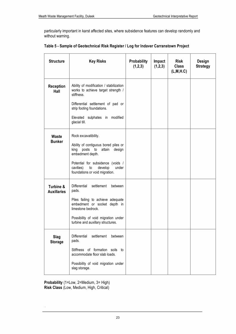
Meath Waste Management Facility, Duleek Geotechnical Interpretative Report
23
particularly important in karst affected sites, where subsidence features can develop randomly and without warning. Table 5 - Sample of Geotechnical Risk Register / Log for Indaver Carranstown Project
Structure
Key Risks
Probability (1,2,3)
Impact (1,2,3)
Risk
Class (L,M,H.C)
Design
Strategy
Reception
Hall
Ability of modification / stabilization works to achieve target strength / stiffness. Differential settlement of pad or strip footing foundations. Elevated sulphates in modified glacial till.
Waste Bunker
Rock excavatibility. Ability of contiguous bored piles or king posts to attain design embedment depth. Potential for subsidence (voids / cavities) to develop under foundations or void migration.
Turbine & Auxillaries
Differential settlement between pads. Piles failing to achieve adequate embedment or socket depth in limestone bedrock. Possibility of void migration under turbine and auxillary structures.
Slag
Storage
Differential settlement between pads. Stiffness of formation soils to accommodate floor slab loads. Possibility of void migration under slag storage.
Probability (1=Low, 2=Medium, 3= High) Risk Class (Low, Medium, High, Critical)
Meath Waste Management Facility, Duleek Geotechnical Interpretative Report
24
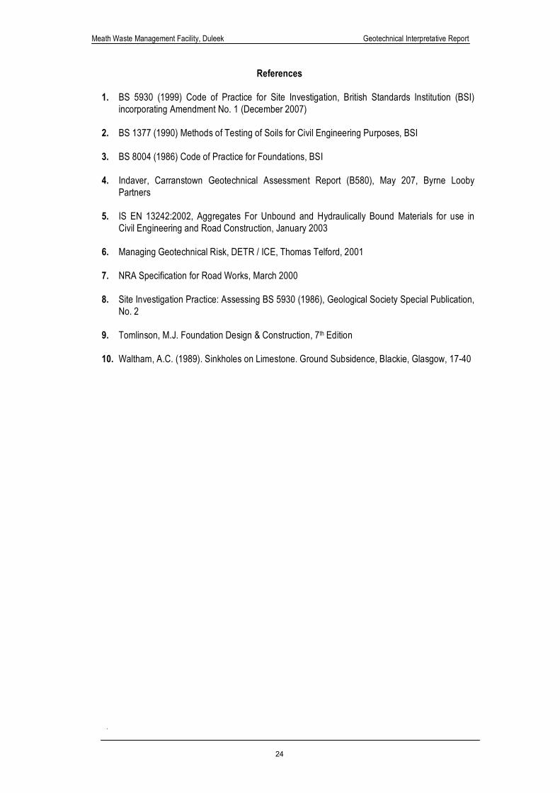
References
1. BS 5930 (1999) Code of Practice for Site Investigation, British Standards Institution (BSI) incorporating Amendment No. 1 (December 2007)
2. BS 1377 (1990) Methods of Testing of Soils for Civil Engineering Purposes, BSI
3. BS 8004 (1986) Code of Practice for Foundations, BSI
4. Indaver, Carranstown Geotechnical Assessment Report (B580), May 207, Byrne Looby
Partners
5. IS EN 13242:2002, Aggregates For Unbound and Hydraulically Bound Materials for use in Civil Engineering and Road Construction, January 2003
6. Managing Geotechnical Risk, DETR / ICE, Thomas Telford, 2001
7. NRA Specification for Road Works, March 2000
8. Site Investigation Practice: Assessing BS 5930 (1986), Geological Society Special Publication,
No. 2
9. Tomlinson, M.J. Foundation Design & Construction, 7th Edition
10. Waltham, A.C. (1989). Sinkholes on Limestone. Ground Subsidence, Blackie, Glasgow, 17-40

Meath Waste Management Facility, Duleek Geotechnical Interpretative Report
25
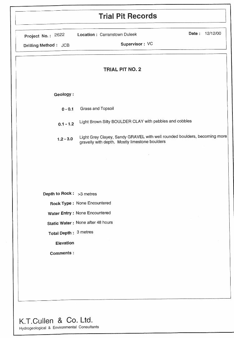
Appendix 9.2
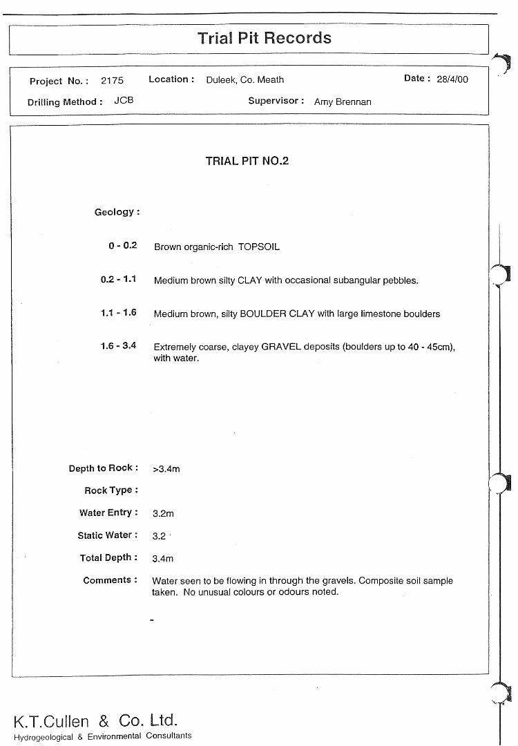
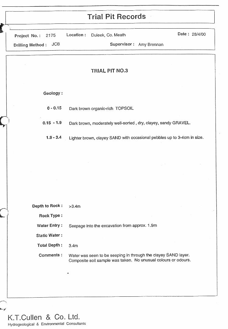
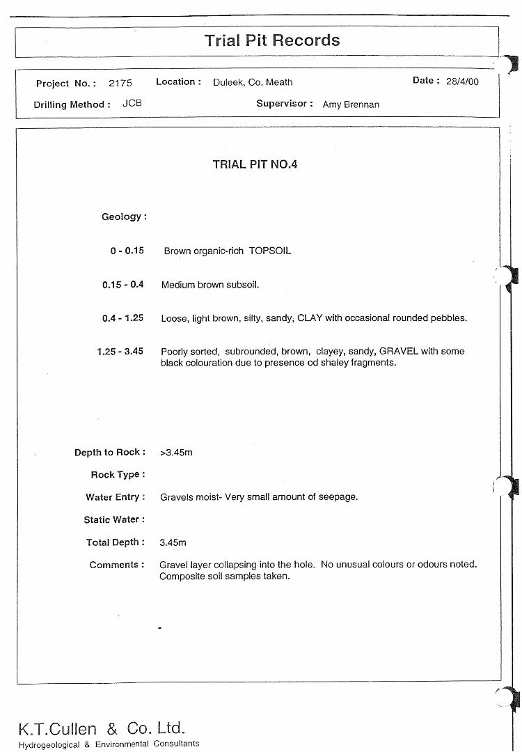
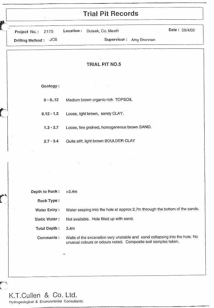
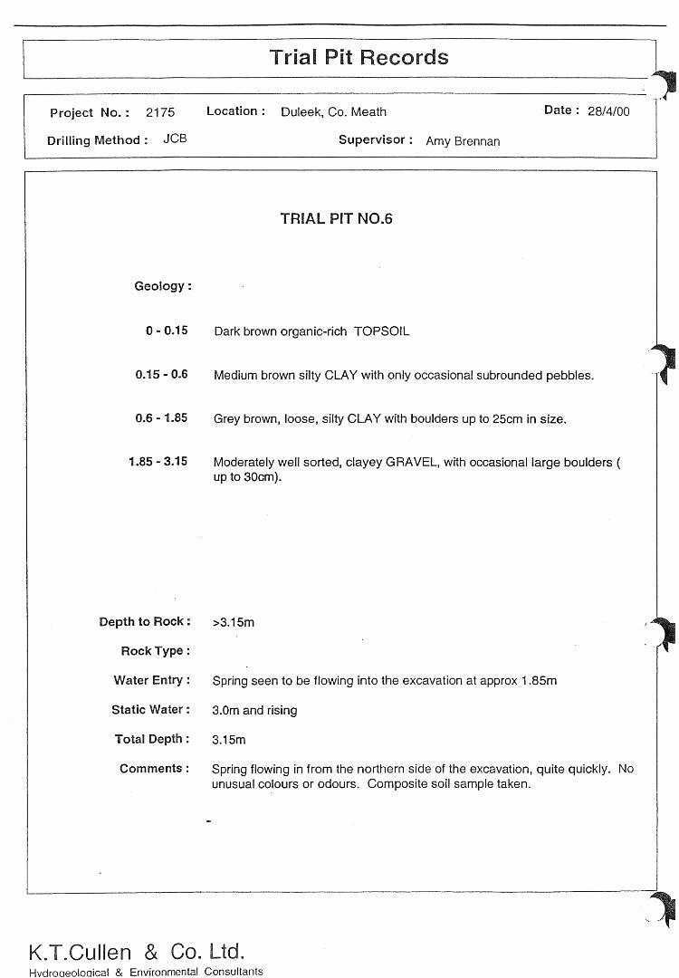
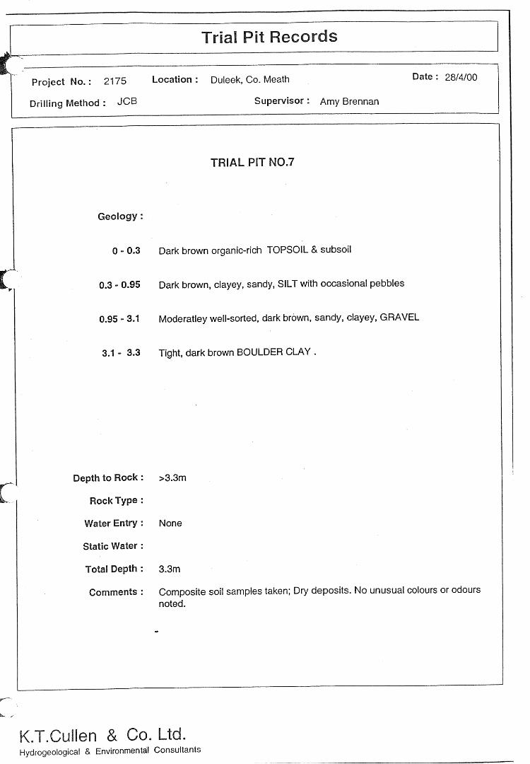
Trial Pit Logs 2000
Appendix 9.3
Soil Sampling Results Tables
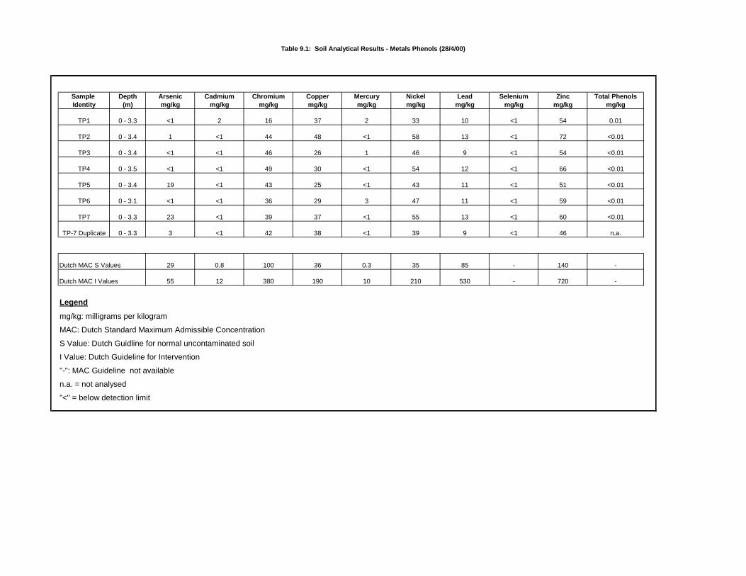
Table 9.1: Soil Analytical Results - Metals Phenols (28/4/00)
Sample Depth Arsenic Cadmium Chromium Copper Mercury Nickel Lead Selenium Zinc Total PhenolsIdentity (m) mg/kg mg/kg mg/kg mg/kg mg/kg mg/kg mg/kg mg/kg mg/kg mg/kg
TP1 0 - 3.3 <1 2 16 37 2 33 10 <1 54 0.01
TP2 0 - 3.4 1 <1 44 48 <1 58 13 <1 72 <0.01
TP3 0 - 3.4 <1 <1 46 26 1 46 9 <1 54 <0.01
TP4 0 - 3.5 <1 <1 49 30 <1 54 12 <1 66 <0.01
TP5 0 - 3.4 19 <1 43 25 <1 43 11 <1 51 <0.01
TP6 0 - 3.1 <1 <1 36 29 3 47 11 <1 59 <0.01
TP7 0 - 3.3 23 <1 39 37 <1 55 13 <1 60 <0.01
TP-7 Duplicate 0 - 3.3 3 <1 42 38 <1 39 9 <1 46 n.a.
Dutch MAC S Values 29 0.8 100 36 0.3 35 85 - 140 -
Dutch MAC I Values 55 12 380 190 10 210 530 - 720 -
Legend
mg/kg: milligrams per kilogram
MAC: Dutch Standard Maximum Admissible Concentration
S Value: Dutch Guidline for normal uncontaminated soil
I Value: Dutch Guideline for Intervention
"-": MAC Guideline not available
n.a. = not analysed
"<" = below detection limit
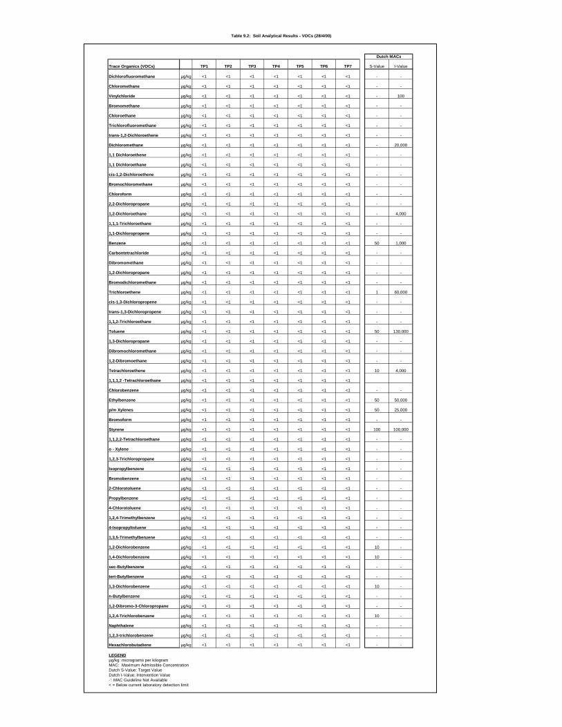
Table 9.2: Soil Analytical Results - VOCs (28/4/00)
Dutch MACs
Trace Organics (VOCs) TP1 TP2 TP3 TP4 TP5 TP6 TP7 S-Value I-Value
Dichlorofluoromethane µg/kg <1 <1 <1 <1 <1 <1 <1 - -
Chloromethane µg/kg <1 <1 <1 <1 <1 <1 <1 - -
Vinylchloride µg/kg <1 <1 <1 <1 <1 <1 <1 - 100
Bromomethane µg/kg <1 <1 <1 <1 <1 <1 <1 - -
Chloroethane µg/kg <1 <1 <1 <1 <1 <1 <1 - -
Trichlorofluoromethane µg/kg <1 <1 <1 <1 <1 <1 <1 - -
trans-1,2-Dichloroethene µg/kg <1 <1 <1 <1 <1 <1 <1 - -
Dichloromethane µg/kg <1 <1 <1 <1 <1 <1 <1 - 20,000
1,1 Dichloroethene µg/kg <1 <1 <1 <1 <1 <1 <1 - -
1,1 Dichloroethane µg/kg <1 <1 <1 <1 <1 <1 <1 - -
cis-1,2-Dichloroethene µg/kg <1 <1 <1 <1 <1 <1 <1 - -
Bromochloromethane µg/kg <1 <1 <1 <1 <1 <1 <1 - -
Chloroform µg/kg <1 <1 <1 <1 <1 <1 <1 - -
2,2-Dichloropropane µg/kg <1 <1 <1 <1 <1 <1 <1 - -
1,2-Dichloroethane µg/kg <1 <1 <1 <1 <1 <1 <1 - 4,000
1,1,1-Trichloroethane µg/kg <1 <1 <1 <1 <1 <1 <1 - -
1,1-Dichloropropene µg/kg <1 <1 <1 <1 <1 <1 <1 - -
Benzene µg/kg <1 <1 <1 <1 <1 <1 <1 50 1,000
Carbontetrachloride µg/kg <1 <1 <1 <1 <1 <1 <1 - -
Dibromomethane µg/kg <1 <1 <1 <1 <1 <1 <1 - -
1,2-Dichloropropane µg/kg <1 <1 <1 <1 <1 <1 <1 - -
Bromodichloromethane µg/kg <1 <1 <1 <1 <1 <1 <1 - -
Trichloroethene µg/kg <1 <1 <1 <1 <1 <1 <1 1 60,000
cis-1,3-Dichloropropene µg/kg <1 <1 <1 <1 <1 <1 <1 - -
trans-1,3-Dichloropropene µg/kg <1 <1 <1 <1 <1 <1 <1 - -
1,1,2-Trichloroethane µg/kg <1 <1 <1 <1 <1 <1 <1 - -
Toluene µg/kg <1 <1 <1 <1 <1 <1 <1 50 130,000
1,3-Dichloropropane µg/kg <1 <1 <1 <1 <1 <1 <1 - -
Dibromochloromethane µg/kg <1 <1 <1 <1 <1 <1 <1 - -
1,2-Dibromoethane µg/kg <1 <1 <1 <1 <1 <1 <1 - -
Tetrachloroethene µg/kg <1 <1 <1 <1 <1 <1 <1 10 4,000
1,1,1,2 -Tetrachloroethane µg/kg <1 <1 <1 <1 <1 <1 <1
Chlorobenzene µg/kg <1 <1 <1 <1 <1 <1 <1 - -
Ethylbenzene µg/kg <1 <1 <1 <1 <1 <1 <1 50 50,000
p/m Xylenes µg/kg <1 <1 <1 <1 <1 <1 <1 50 25,000
Bromoform µg/kg <1 <1 <1 <1 <1 <1 <1 - -
Styrene µg/kg <1 <1 <1 <1 <1 <1 <1 100 100,000
1,1,2,2-Tetrachloroethane µg/kg <1 <1 <1 <1 <1 <1 <1 - -
o - Xylene µg/kg <1 <1 <1 <1 <1 <1 <1 - -
1,2,3-Trichloropropane µg/kg <1 <1 <1 <1 <1 <1 <1 - -
Isopropylbenzene µg/kg <1 <1 <1 <1 <1 <1 <1 - -
Bromobenzene µg/kg <1 <1 <1 <1 <1 <1 <1 - -
2-Chlorotoluene µg/kg <1 <1 <1 <1 <1 <1 <1 - -
Propylbenzene µg/kg <1 <1 <1 <1 <1 <1 <1 - -
4-Chlorotoluene µg/kg <1 <1 <1 <1 <1 <1 <1 - -
1,2,4-Trimethylbenzene µg/kg <1 <1 <1 <1 <1 <1 <1 - -
4-Isopropyltoluene µg/kg <1 <1 <1 <1 <1 <1 <1 - -
1,3,5-Trimethylbenzene µg/kg <1 <1 <1 <1 <1 <1 <1 - -
1,2-Dichlorobenzene µg/kg <1 <1 <1 <1 <1 <1 <1 10 -
1,4-Dichlorobenzene µg/kg <1 <1 <1 <1 <1 <1 <1 10 -
sec-Butylbenzene µg/kg <1 <1 <1 <1 <1 <1 <1 - -
tert-Butylbenzene µg/kg <1 <1 <1 <1 <1 <1 <1 - -
1,3-Dichlorobenzene µg/kg <1 <1 <1 <1 <1 <1 <1 10 -
n-Butylbenzene µg/kg <1 <1 <1 <1 <1 <1 <1 - -
1,2-Dibromo-3-Chloropropane µg/kg <1 <1 <1 <1 <1 <1 <1 - -
1,2,4-Trichlorobenzene µg/kg <1 <1 <1 <1 <1 <1 <1 10 -
Naphthalene µg/kg <1 <1 <1 <1 <1 <1 <1 - -
1,2,3-trichlorobenzene µg/kg <1 <1 <1 <1 <1 <1 <1 - -
Hexachlorobutadiene µg/kg <1 <1 <1 <1 <1 <1 <1 - -
LEGENDµg/kg: micrograms per kilogramMAC: Maximum Admissible Concentration Dutch S-Value: Target ValueDutch I-Value: Intervention Value-': MAC Guideline Not Available< = Below current laboratory detection limit
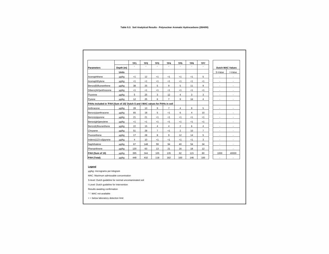
Table 9.3: Soil Analytical Results - Polynuclear Aroma tic Hydrocarbons (28/4/00)
TP1 TP2 TP3 TP4 TP5 TP6 TP7
Parameters Depth (m)- - - - - - -
Units S-Value I-Value
Acenaphthene µg/kg <1 12 <1 <1 <1 <1 5 - -
Acenaphthylene µg/kg <1 <1 <1 <1 <1 <1 <1 - -
Benzo(B)fluoranthene µg/kg 38 25 5 9 5 11 9 - -
Dibenz(AH)anthracene µg/kg <1 <1 <1 <1 <1 <1 <1 - -
Fluorene µg/kg 5 25 3 12 4 3 3 - -
Pyrene µg/kg 12 25 6 7 9 16 4 - -
PAHs included in 'PAH (Sum of 10)' Dutch S and I MAC va lues for PAHs in soil
Anthracene µg/kg 28 13 9 7 4 9 5 - -
Benzo(a)anthracene µg/kg 65 18 5 <1 6 4 10 - -
Benzo(a)pyrene µg/kg 21 21 <1 <1 <1 <1 <1 - -
Benzo(ghi)perylene µg/kg <1 <1 <1 <1 <1 <1 <1 - -
Benzo(k)flouranthene µg/kg 22 15 4 4 2 6 4 - -
Chrysene µg/kg 51 28 7 <1 2 10 7 - -
Fluoranthene µg/kg 17 28 8 9 12 14 5 - -
Indeno(123-cd)pyrene µg/kg 4 10 <1 <1 <1 <1 3 - -
Naphthalene µg/kg 67 148 59 94 40 54 34 - -
Phenanthrene µg/kg 120 63 13 21 16 18 12 - -
PAH (Sum of 10) µg/kg 395 344 105 135 82 115 80 1000 40000
PAH (Total) µg/kg 449 432 118 162 100 146 100 - -
Legend
µg/kg: micrograms per kilogram
MAC: Maximum admissable concentration
S-level: Dutch guideline for normal uncontaminated soil
I-Level: Dutch guideline for Intervention
Results awaiting confirmation
"-": MAC not available
< = below laboratory detection limit
Dutch MAC Values
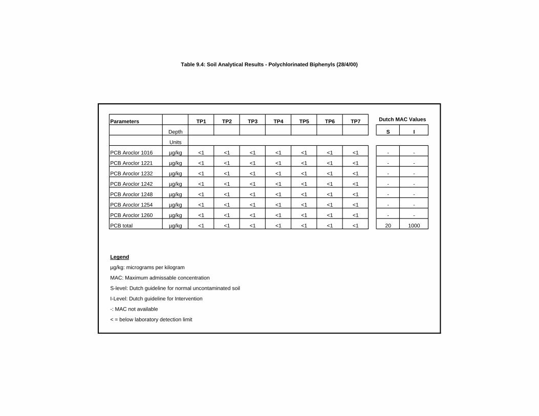
Table 9.4: Soil Analytical Results - Polychlorinated Biphenyls (28/4/00)
Parameters TP1 TP2 TP3 TP4 TP5 TP6 TP7
Depth S I
Units
PCB Aroclor 1016 µg/kg <1 <1 <1 <1 <1 <1 <1 - -
PCB Aroclor 1221 µg/kg <1 <1 <1 <1 <1 <1 <1 - -
PCB Aroclor 1232 µg/kg <1 <1 <1 <1 <1 <1 <1 - -
PCB Aroclor 1242 µg/kg <1 <1 <1 <1 <1 <1 <1 - -
PCB Aroclor 1248 µg/kg <1 <1 <1 <1 <1 <1 <1 - -
PCB Aroclor 1254 µg/kg <1 <1 <1 <1 <1 <1 <1 - -
PCB Aroclor 1260 µg/kg <1 <1 <1 <1 <1 <1 <1 - -
PCB total µg/kg <1 <1 <1 <1 <1 <1 <1 20 1000
Legend
µg/kg: micrograms per kilogram
MAC: Maximum admissable concentration
S-level: Dutch guideline for normal uncontaminated soil
I-Level: Dutch guideline for Intervention
-: MAC not available
< = below laboratory detection limit
Dutch MAC Values
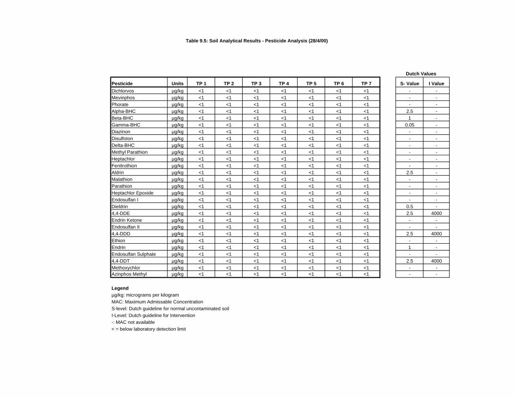
Table 9.5: Soil Analytical Results - Pesticide Analysis (28/4/00)
Dutch Values
Pesticide Units TP 1 TP 2 TP 3 TP 4 TP 5 TP 6 TP 7 S- Value I Value
Dichlorvos µg/kg <1 <1 <1 <1 <1 <1 <1 - -Mevinphos µg/kg <1 <1 <1 <1 <1 <1 <1 - -Phorate µg/kg <1 <1 <1 <1 <1 <1 <1 - -Alpha-BHC µg/kg <1 <1 <1 <1 <1 <1 <1 2.5 -Beta-BHC µg/kg <1 <1 <1 <1 <1 <1 <1 1 -Gamma-BHC µg/kg <1 <1 <1 <1 <1 <1 <1 0.05 -Diazinon µg/kg <1 <1 <1 <1 <1 <1 <1 - -Disulfoton µg/kg <1 <1 <1 <1 <1 <1 <1 - -Delta-BHC µg/kg <1 <1 <1 <1 <1 <1 <1 - -Methyl Parathion µg/kg <1 <1 <1 <1 <1 <1 <1 - -Heptachlor µg/kg <1 <1 <1 <1 <1 <1 <1 - -Fenitrothion µg/kg <1 <1 <1 <1 <1 <1 <1 - -Aldrin µg/kg <1 <1 <1 <1 <1 <1 <1 2.5 -Malathion µg/kg <1 <1 <1 <1 <1 <1 <1 - -Parathion µg/kg <1 <1 <1 <1 <1 <1 <1 - -Heptachlor Epoxide µg/kg <1 <1 <1 <1 <1 <1 <1 - -Endosulfan I µg/kg <1 <1 <1 <1 <1 <1 <1 - -Dieldrin µg/kg <1 <1 <1 <1 <1 <1 <1 0.5 -4,4-DDE µg/kg <1 <1 <1 <1 <1 <1 <1 2.5 4000Endrin Ketone µg/kg <1 <1 <1 <1 <1 <1 <1 - -Endosulfan II µg/kg <1 <1 <1 <1 <1 <1 <1 - -4,4-DDD µg/kg <1 <1 <1 <1 <1 <1 <1 2.5 4000Ethion µg/kg <1 <1 <1 <1 <1 <1 <1 - -Endrin µg/kg <1 <1 <1 <1 <1 <1 <1 1 -Endosulfan Sulphate µg/kg <1 <1 <1 <1 <1 <1 <1 - -4,4-DDT µg/kg <1 <1 <1 <1 <1 <1 <1 2.5 4000Methoxychlor µg/kg <1 <1 <1 <1 <1 <1 <1 - -Azinphos Methyl µg/kg <1 <1 <1 <1 <1 <1 <1 - -
Legendµg/kg: micrograms per kilogramMAC: Maximum Admissable ConcentrationS-level: Dutch guideline for normal uncontaminated soilI-Level: Dutch guideline for Intervention-: MAC not available < = below laboratory detection limit

Appendix 9.4
Puraflo Report


Appendix 9.5
Puraflo Design and Certification