Embed Size (px)
Citation preview

Keeyask Infrastructure Appendix A Environmental Assessment
APPENDIX A
PROJECT DESCRIPTION

Keeyask Infrastructure Appendix A1 Environmental Assessment
Appendix A1
Concept Design for Wastewater Disposal

G1
G2
G3
G4
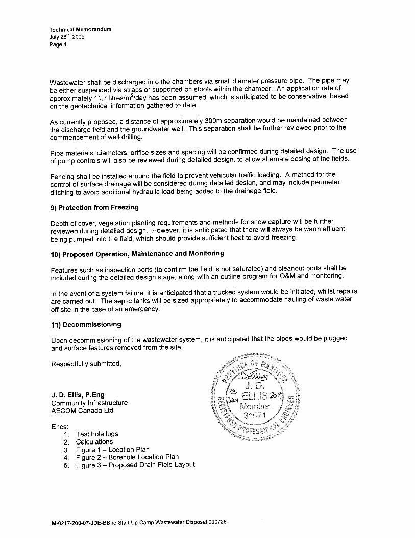
ORGANICS - peat moss, rootmat, wet
CLAY - some silt, trace sand, trace rootlets- brown, moist, soft, high plasticity
CLAY and SAND - some silt, brown, moist, stiff, highplasticity, fine to medium grained sandSAND - some silt, trace clay
- light brown, moist, dense, fine grained
- clayey below 1.2 m
- some clay below 1.5 m
- trace clay, moist to wet, compact below 1.8 m
CLAY - some silt, trace sand- moist, stiff, high plasticity
END OF TEST HOLE AT 3.0 m IN CLAYNotes:1) Trace seepage observed in SAND at 1.8 m belowground surface.2) Sloughing observed in SAND.3) Water level at 2.4 m below ground surface immediatelyafter drilling.4) Installed 25 mm standpipe.5) Water level in standpipe on July 22, 2009 was 2.90 mbelow ground surface.
DEPT
H (m
)
1
2
3
4
Page 1 of 1
LOGGED BY: Jared BaldwinREVIEWED BY: Gil RobinsonPROJECT ENGINEER: Gil Robinson
COMPLETION DEPTH: 3.05 mCOMPLETION DATE: 21/7/09
0
DRAFT
LOG
OF
TES
T H
OLE
DR
AFT
021
7-20
0-07
- TE
ST
HO
LE L
OG
S.G
PJ
UM
A W
INN
.GD
T 2
4/7/
09
ELEV
ATIO
N
98
97
96
95
BULK
CLIENT: Manitoba Hydro
METHOD: 50 mm Hand AugerSAMPLE TYPE
TESTHOLE NO: TH-09-01PROJECT NO.: 0217-200-07ELEVATION (m): 98.88
SHELBY TUBEGRAB SPLIT SPOON NO RECOVERY
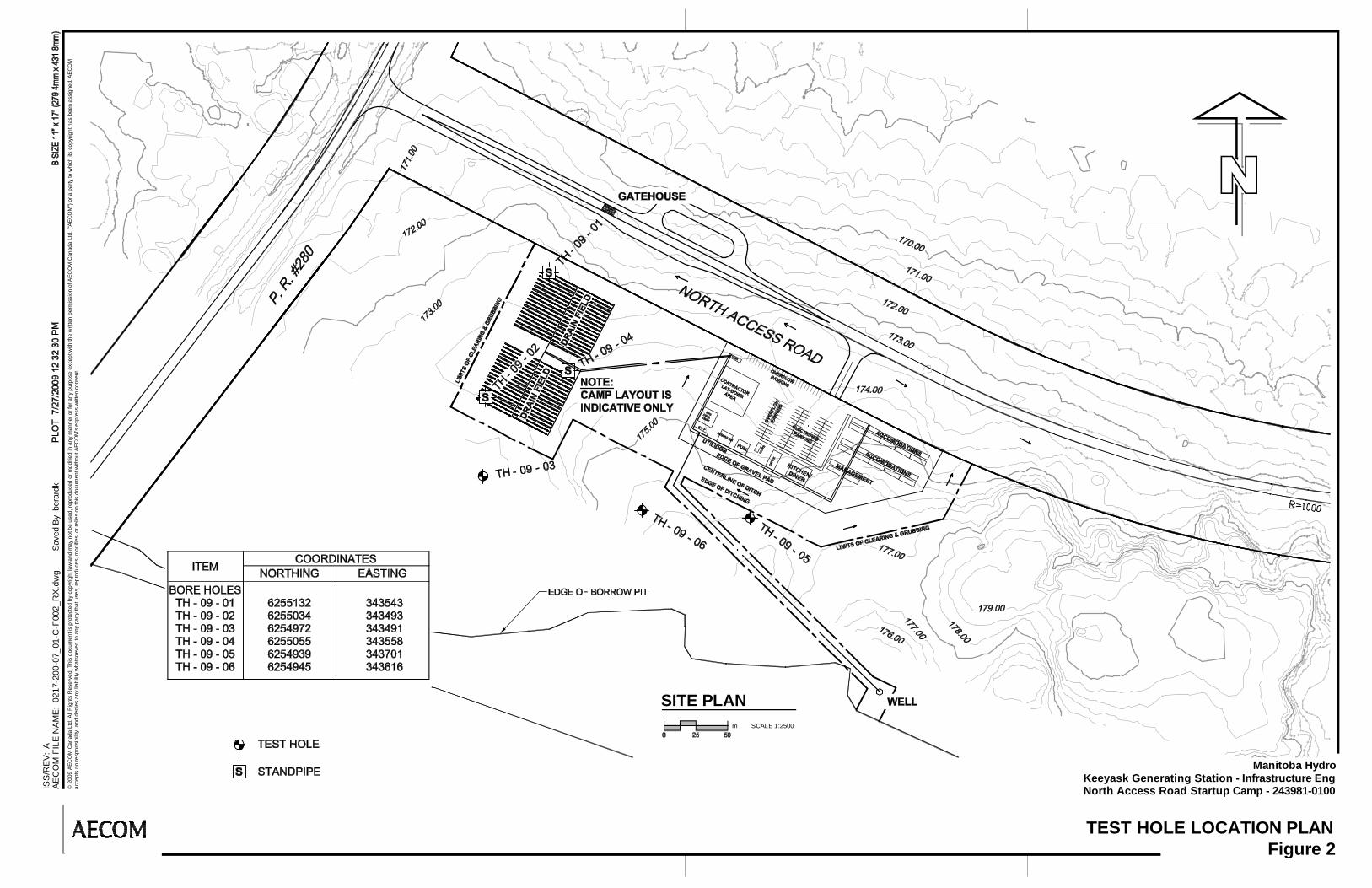
PROJECT: Keeyask Generating Station InfrastructureLOCATION: Start-Up Camp, UTM 15 V, E - 343543, N - 6255132CONTRACTOR:
CORE
GRAVELBACKFILL TYPE BENTONITE SANDGROUT CUTTINGSSLOUGH
COMMENTS
UNDRAINED SHEAR STRENGTH Torvane
QU
Field Vane
Lab Vane
Pocket Pen.
(kPa)
50 100 150 200
SAMP
LE T
YPE
0(Blows/300mm)
PENETRATION TESTS
Total Unit Wt (kN/m3)
20 40 60 80
21
Becker Dynamic Cone
SPT (Standard Pen Test)
Plastic LiquidMC
100
100
16 17 18 19 20
SPT
(N)
SAMP
LE #
SOIL DESCRIPTION
SOIL
SYMB
OL
20 40 60 80
G6
G7
G8
G9
G10
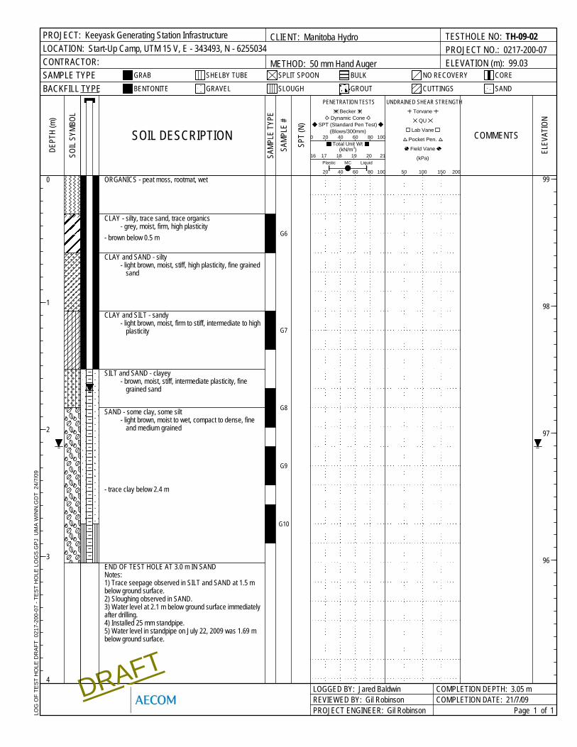
ORGANICS - peat moss, rootmat, wet
CLAY - silty, trace sand, trace organics- grey, moist, firm, high plasticity
- brown below 0.5 m
CLAY and SAND - silty- light brown, moist, stiff, high plasticity, fine grained
sand
CLAY and SILT - sandy- light brown, moist, firm to stiff, intermediate to high
plasticity
SILT and SAND - clayey- brown, moist, stiff, intermediate plasticity, fine
grained sand
SAND - some clay, some silt- light brown, moist to wet, compact to dense, fine
and medium grained
- trace clay below 2.4 m
END OF TEST HOLE AT 3.0 m IN SANDNotes:1) Trace seepage observed in SILT and SAND at 1.5 mbelow ground surface.2) Sloughing observed in SAND.3) Water level at 2.1 m below ground surface immediatelyafter drilling.4) Installed 25 mm standpipe.5) Water level in standpipe on July 22, 2009 was 1.69 mbelow ground surface.
DEPT
H (m
)
1
2
3
4
Page 1 of 1
LOGGED BY: Jared BaldwinREVIEWED BY: Gil RobinsonPROJECT ENGINEER: Gil Robinson
COMPLETION DEPTH: 3.05 mCOMPLETION DATE: 21/7/09
0
DRAFT
LOG
OF
TES
T H
OLE
DR
AFT
021
7-20
0-07
- TE
ST
HO
LE L
OG
S.G
PJ
UM
A W
INN
.GD
T 2
4/7/
09
ELEV
ATIO
N
99
98
97
96
BULK
CLIENT: Manitoba Hydro
METHOD: 50 mm Hand AugerSAMPLE TYPE
TESTHOLE NO: TH-09-02PROJECT NO.: 0217-200-07ELEVATION (m): 99.03
SHELBY TUBEGRAB SPLIT SPOON NO RECOVERY
PROJECT: Keeyask Generating Station InfrastructureLOCATION: Start-Up Camp, UTM 15 V, E - 343493, N - 6255034CONTRACTOR:
CORE
GRAVELBACKFILL TYPE BENTONITE SANDGROUT CUTTINGSSLOUGH
COMMENTS
UNDRAINED SHEAR STRENGTH Torvane
QU
Field Vane
Lab Vane
Pocket Pen.
(kPa)
50 100 150 200
SAMP
LE T
YPE
0(Blows/300mm)
PENETRATION TESTS
Total Unit Wt (kN/m3)
20 40 60 80
21
Becker Dynamic Cone
SPT (Standard Pen Test)
Plastic LiquidMC
100
100
16 17 18 19 20
SPT
(N)
SAMP
LE #
SOIL DESCRIPTION
SOIL
SYMB
OL
20 40 60 80
G11
G12
G13
G14
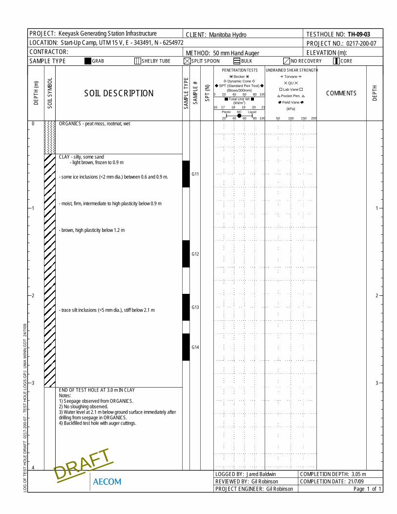
ORGANICS - peat moss, rootmat, wet
CLAY - silty, some sand- light brown, frozen to 0.9 m
- some ice inclusions (<2 mm dia.) between 0.6 and 0.9 m.
- moist, firm, intermediate to high plasticity below 0.9 m
- brown, high plasticity below 1.2 m
- trace silt inclusions (<5 mm dia.), stiff below 2.1 m
END OF TEST HOLE AT 3.0 m IN CLAYNotes:1) Seepage observed from ORGANICS.2) No sloughing observed.3) Water level at 2.1 m below ground surface immediately afterdrilling from seepage in ORGANICS.4) Backfilled test hole with auger cuttings.
DEPT
H (m
)
1
2
3DE
PTH
1
2
3
4
Page 1 of 1
LOGGED BY: Jared BaldwinREVIEWED BY: Gil RobinsonPROJECT ENGINEER: Gil Robinson
COMPLETION DEPTH: 3.05 mCOMPLETION DATE: 21/7/09
0
DRAFT
LOG
OF
TES
T H
OLE
DR
AFT
021
7-20
0-07
- TE
ST
HO
LE L
OG
S.G
PJ
UM
A W
INN
.GD
T 2
4/7/
09
BULK
CLIENT: Manitoba Hydro
METHOD: 50 mm Hand AugerSAMPLE TYPE
TESTHOLE NO: TH-09-03PROJECT NO.: 0217-200-07ELEVATION (m):
SHELBY TUBEGRAB SPLIT SPOON NO RECOVERY
PROJECT: Keeyask Generating Station InfrastructureLOCATION: Start-Up Camp, UTM 15 V, E - 343491, N - 6254972CONTRACTOR:
CORE
COMMENTS
UNDRAINED SHEAR STRENGTH Torvane
QU
Field Vane
Lab Vane
Pocket Pen.
(kPa)
50 100 150 200
SAMP
LE T
YPE
0(Blows/300mm)
PENETRATION TESTS
Total Unit Wt (kN/m3)
20 40 60 80
21
Becker Dynamic Cone
SPT (Standard Pen Test)
Plastic LiquidMC
100
100
16 17 18 19 20
SPT
(N)
SAMP
LE #
SOIL DESCRIPTION
SOIL
SYMB
OL
20 40 60 80
ORGANICS - peat moss, rootmat, wet
CLAY - silty, trace to some sand- brown, frozen to 1.1 m
- trace ice inclusions (<1 mm dia.) between 0.6 and 1.1 m
- moist, firm, high plasticity below 1.1 m
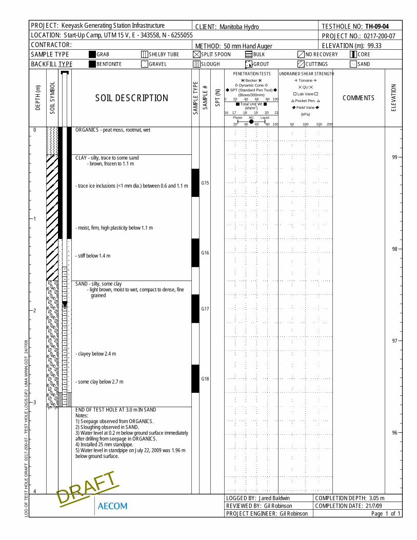
- stiff below 1.4 m
SAND - silty, some clay- light brown, moist to wet, compact to dense, fine
grained
- clayey below 2.4 m
- some clay below 2.7 m
END OF TEST HOLE AT 3.0 m IN SANDNotes:1) Seepage observed from ORGANICS.2) Sloughing observed in SAND.3) Water level at 0.2 m below ground surface immediatelyafter drilling from seepage in ORGANICS.4) Installed 25 mm standpipe.5) Water level in standpipe on July 22, 2009 was 1.96 mbelow ground surface.
G15
G16
G17
G18
DEPT
H (m
)
1
2
3
4
Page 1 of 1
LOGGED BY: Jared BaldwinREVIEWED BY: Gil RobinsonPROJECT ENGINEER: Gil Robinson
COMPLETION DEPTH: 3.05 mCOMPLETION DATE: 21/7/09
0
DRAFT
LOG
OF
TES
T H
OLE
DR
AFT
021
7-20
0-07
- TE
ST
HO
LE L
OG
S.G
PJ
UM
A W
INN
.GD
T 2
4/7/
09
ELEV
ATIO
N
99
98
97
96
BULK
CLIENT: Manitoba Hydro
METHOD: 50 mm Hand AugerSAMPLE TYPE
TESTHOLE NO: TH-09-04PROJECT NO.: 0217-200-07ELEVATION (m): 99.33
SHELBY TUBEGRAB SPLIT SPOON NO RECOVERY
PROJECT: Keeyask Generating Station InfrastructureLOCATION: Start-Up Camp, UTM 15 V, E - 343558, N - 6255055CONTRACTOR:
CORE
GRAVELBACKFILL TYPE BENTONITE SANDGROUT CUTTINGSSLOUGH
COMMENTS
UNDRAINED SHEAR STRENGTH Torvane
QU
Field Vane
Lab Vane
Pocket Pen.
(kPa)
50 100 150 200
SOIL
SYMB
OL
SAMP
LE T
YPE
0(Blows/300mm)
PENETRATION TESTS
Total Unit Wt (kN/m3)
20 40 60 80
21
Becker Dynamic Cone
SPT (Standard Pen Test)
Plastic LiquidMC
100
100
16 17 18 19 20
SPT
(N)
SAMP
LE #
SOIL DESCRIPTION
20 40 60 80
G19
G20
G21
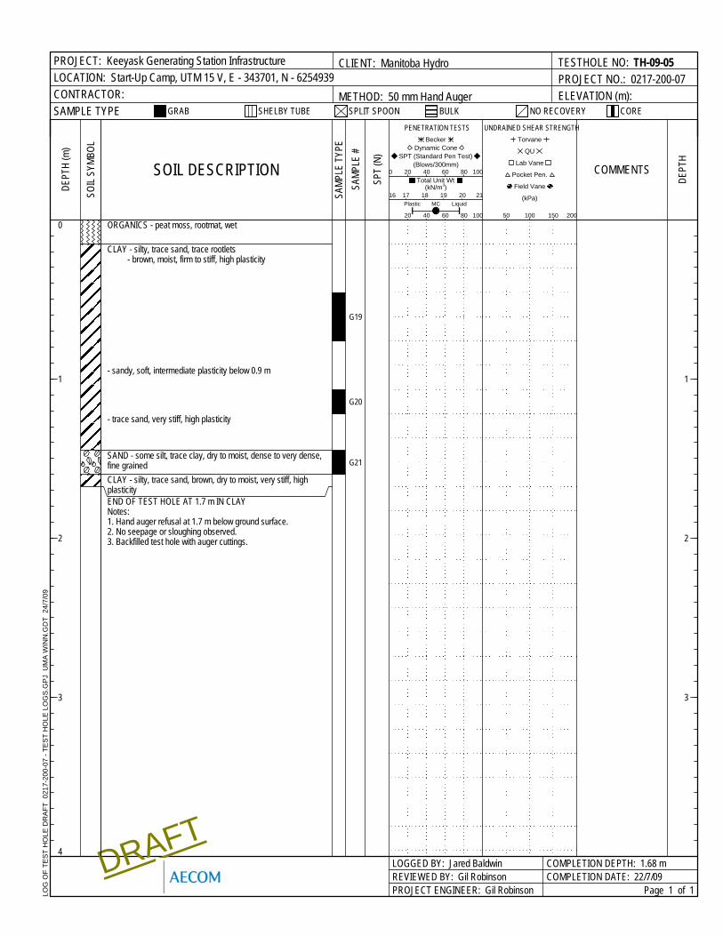
ORGANICS - peat moss, rootmat, wet
CLAY - silty, trace sand, trace rootlets- brown, moist, firm to stiff, high plasticity
- sandy, soft, intermediate plasticity below 0.9 m
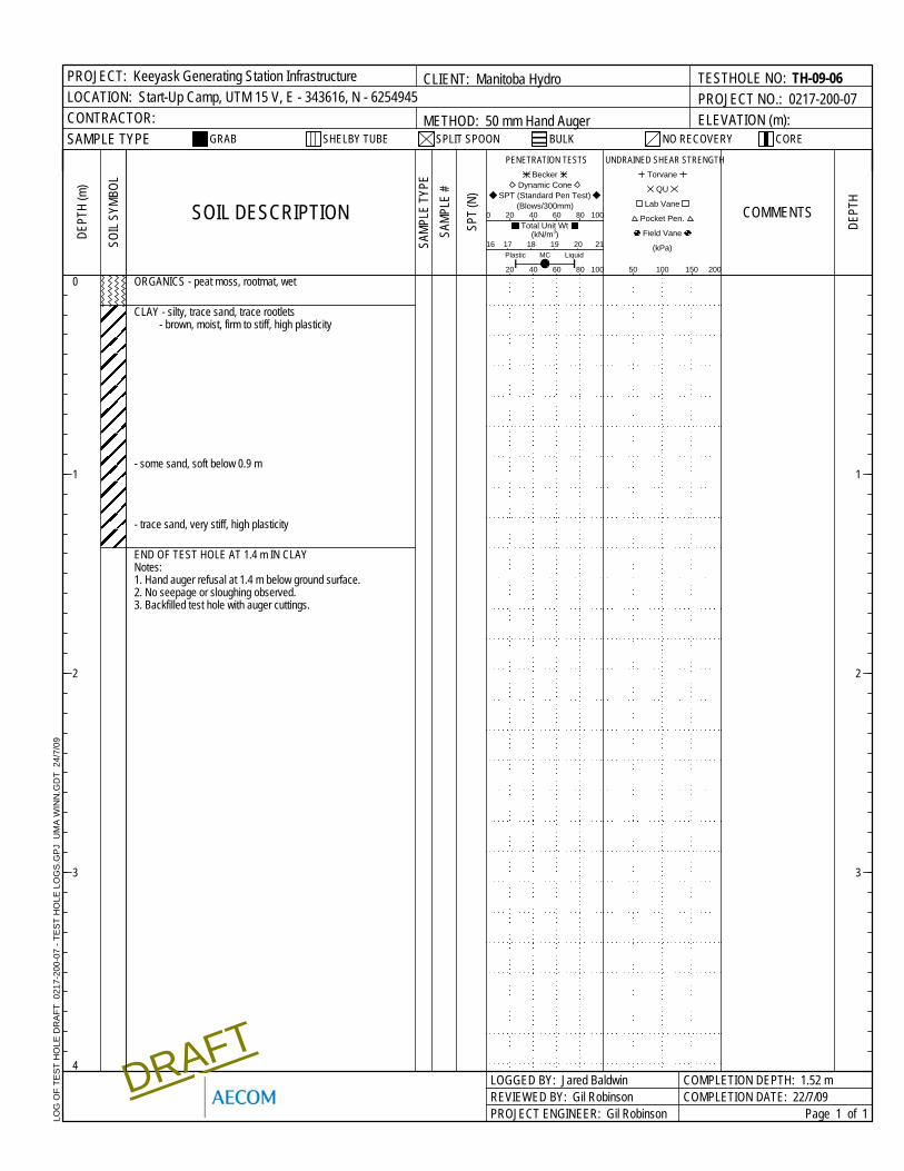
- trace sand, very stiff, high plasticity
SAND - some silt, trace clay, dry to moist, dense to very dense,fine grainedCLAY - silty, trace sand, brown, dry to moist, very stiff, highplasticityEND OF TEST HOLE AT 1.7 m IN CLAYNotes:1. Hand auger refusal at 1.7 m below ground surface.2. No seepage or sloughing observed.3. Backfilled test hole with auger cuttings.
DEPT
H (m
)
1
2
3DE
PTH
1
2
3
4
Page 1 of 1
LOGGED BY: Jared BaldwinREVIEWED BY: Gil RobinsonPROJECT ENGINEER: Gil Robinson
COMPLETION DEPTH: 1.68 mCOMPLETION DATE: 22/7/09
0
DRAFT
LOG
OF
TES
T H
OLE
DR
AFT
021
7-20
0-07
- TE
ST
HO
LE L
OG
S.G
PJ
UM
A W
INN
.GD
T 2
4/7/
09
BULK
CLIENT: Manitoba Hydro
METHOD: 50 mm Hand AugerSAMPLE TYPE
TESTHOLE NO: TH-09-05PROJECT NO.: 0217-200-07ELEVATION (m):
SHELBY TUBEGRAB SPLIT SPOON NO RECOVERY
PROJECT: Keeyask Generating Station InfrastructureLOCATION: Start-Up Camp, UTM 15 V, E - 343701, N - 6254939CONTRACTOR:
CORE
COMMENTS
UNDRAINED SHEAR STRENGTH Torvane
QU
Field Vane
Lab Vane
Pocket Pen.
(kPa)
50 100 150 200
SAMP
LE T
YPE
0(Blows/300mm)
PENETRATION TESTS
Total Unit Wt (kN/m3)
20 40 60 80
21
Becker Dynamic Cone
SPT (Standard Pen Test)
Plastic LiquidMC
100
100
16 17 18 19 20
SPT
(N)
SAMP
LE #
SOIL DESCRIPTION
SOIL
SYMB
OL
20 40 60 80
ORGANICS - peat moss, rootmat, wet
CLAY - silty, trace sand, trace rootlets- brown, moist, firm to stiff, high plasticity
- some sand, soft below 0.9 m
- trace sand, very stiff, high plasticity
END OF TEST HOLE AT 1.4 m IN CLAYNotes:1. Hand auger refusal at 1.4 m below ground surface.2. No seepage or sloughing observed.3. Backfilled test hole with auger cuttings.
DEPT
H (m
)
1
2
3DE
PTH
1
2
3
4
Page 1 of 1
LOGGED BY: Jared BaldwinREVIEWED BY: Gil RobinsonPROJECT ENGINEER: Gil Robinson
COMPLETION DEPTH: 1.52 mCOMPLETION DATE: 22/7/09
0
DRAFT
LOG
OF
TES
T H
OLE
DR
AFT
021
7-20
0-07
- TE
ST
HO
LE L
OG
S.G
PJ
UM
A W
INN
.GD
T 2
4/7/
09
BULK
CLIENT: Manitoba Hydro
METHOD: 50 mm Hand AugerSAMPLE TYPE
TESTHOLE NO: TH-09-06PROJECT NO.: 0217-200-07ELEVATION (m):
SHELBY TUBEGRAB SPLIT SPOON NO RECOVERY
PROJECT: Keeyask Generating Station InfrastructureLOCATION: Start-Up Camp, UTM 15 V, E - 343616, N - 6254945CONTRACTOR:
CORE
COMMENTS
UNDRAINED SHEAR STRENGTH Torvane
QU
Field Vane
Lab Vane
Pocket Pen.
(kPa)
50 100 150 200
SAMP
LE T
YPE
0(Blows/300mm)
PENETRATION TESTS
Total Unit Wt (kN/m3)
20 40 60 80
21
Becker Dynamic Cone
SPT (Standard Pen Test)
Plastic LiquidMC
100
100
16 17 18 19 20
SPT
(N)
SAMP
LE #
SOIL DESCRIPTION
SOIL
SYMB
OL
20 40 60 80
AECOM99 Commerce DriveWinnipeg, MB R3P OY7Canada
CLIENT: MANITOBA HYDROPROJECT: KEEYASK GENERATING STATION
STARTUP CAMPPROJECT NO: 0217-200-07
DATE: 7/27/2009DESIGNED BY: ADAM BRAUN
CHECKED BY: JAMIE ELLIS
Ref Notes: Output
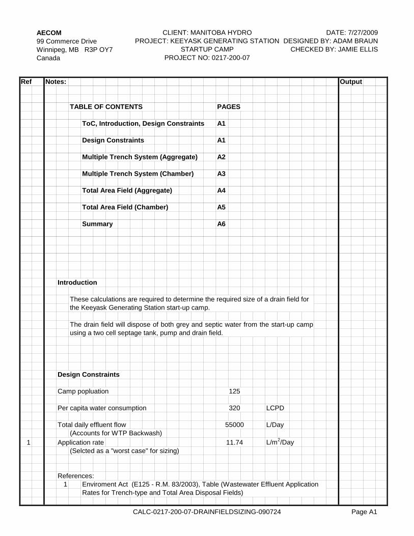
TABLE OF CONTENTS PAGES
ToC, Introduction, Design Constraints A1
Design Constraints A1
Multiple Trench System (Aggregate) A2
Multiple Trench System (Chamber) A3
Total Area Field (Aggregate) A4
Total Area Field (Chamber) A5
Summary A6
Introduction
Design Constraints
Camp popluation
Per capita water consumption LCPD
Total daily effluent flow L/Day(Accounts for WTP Backwash)
1 Application rate L/m2/Day(Selcted as a "worst case" for sizing)
References:1 Enviroment Act (E125 - R.M. 83/2003), Table (Wastewater Effluent Application
Rates for Trench-type and Total Area Disposal Fields)
These calculations are required to determine the required size of a drain field forthe Keeyask Generating Station start-up camp.
The drain field will dispose of both grey and septic water from the start-up campusing a two cell septage tank, pump and drain field.
55000
320
125
11.74
CALC-0217-200-07-DRAINFIELDSIZING-090724 Page A1
AECOM99 Commerce DriveWinnipeg, MB R3P OY7Canada
CLIENT: MANITOBA HYDROPROJECT: KEEYASK GENERATING STATION
STARTUP CAMPPROJECT NO: 0217-200-07
DATE: 7/27/2009DESIGNED BY: ADAM BRAUN
CHECKED BY: JAMIE ELLIS
Ref Notes: Output
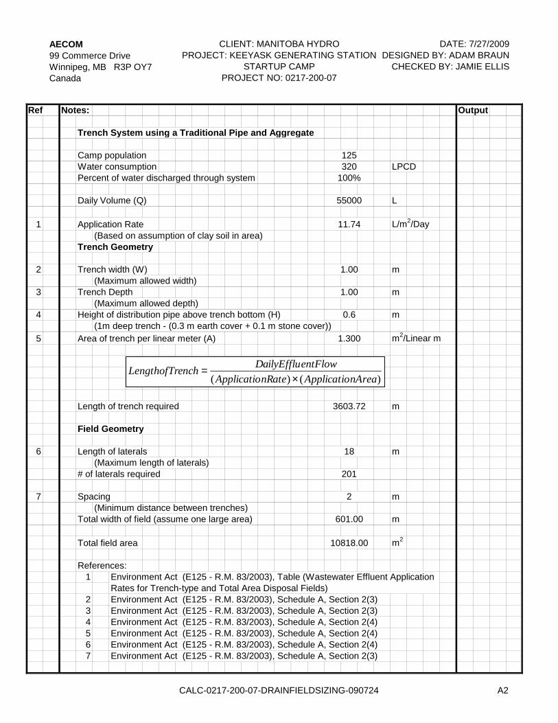
Trench System using a Traditional Pipe and Aggregate
Camp populationWater consumption LPCDPercent of water discharged through system
Daily Volume (Q) L
1 Application Rate L/m2/Day(Based on assumption of clay soil in area)
Trench Geometry
2 Trench width (W) m(Maximum allowed width)
3 Trench Depth m(Maximum allowed depth)
4 Height of distribution pipe above trench bottom (H) m(1m deep trench - (0.3 m earth cover + 0.1 m stone cover))
5 Area of trench per linear meter (A) m2/Linear m
Length of trench required m
Field Geometry
6 Length of laterals m(Maximum length of laterals)
# of laterals required
7 Spacing m(Minimum distance between trenches)
Total width of field (assume one large area) m
Total field area m2
References:1
2 Environment Act (E125 - R.M. 83/2003), Schedule A, Section 2(3)3 Environment Act (E125 - R.M. 83/2003), Schedule A, Section 2(3)4 Environment Act (E125 - R.M. 83/2003), Schedule A, Section 2(4)5 Environment Act (E125 - R.M. 83/2003), Schedule A, Section 2(4)6 Environment Act (E125 - R.M. 83/2003), Schedule A, Section 2(4)7 Environment Act (E125 - R.M. 83/2003), Schedule A, Section 2(3)
Environment Act (E125 - R.M. 83/2003), Table (Wastewater Effluent ApplicationRates for Trench-type and Total Area Disposal Fields)
10818.00
100%320
601.00
3603.72
18
201
2
125
55000
11.74
1.300
0.6
1.00
1.00
)()( nAreaApplicationRateApplicatioentFlowDailyEffluenchLengthofTr
×=
CALC-0217-200-07-DRAINFIELDSIZING-090724 A2
AECOM99 Commerce DriveWinnipeg, MB R3P OY7Canada
CLIENT: MANITOBA HYDROPROJECT: KEEYASK GENERATING STATION
STARTUP CAMPPROJECT NO: 0217-200-07
DATE: 7/27/2009DESIGNED BY: ADAM BRAUN
CHECKED BY: JAMIE ELLIS
Ref Notes: Output
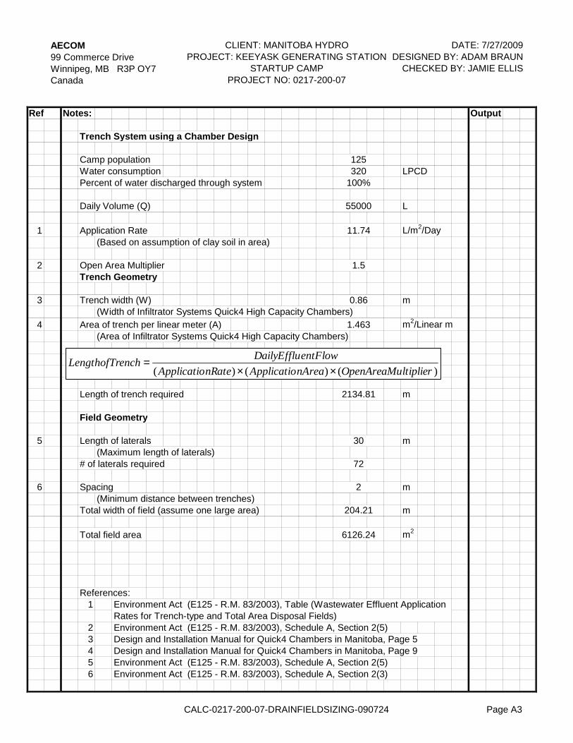
Trench System using a Chamber Design
Camp populationWater consumption LPCDPercent of water discharged through system
Daily Volume (Q) L
1 Application Rate L/m2/Day(Based on assumption of clay soil in area)
2 Open Area MultiplierTrench Geometry
3 Trench width (W) m(Width of Infiltrator Systems Quick4 High Capacity Chambers)
4 Area of trench per linear meter (A) m2/Linear m(Area of Infiltrator Systems Quick4 High Capacity Chambers)
Length of trench required m
Field Geometry
5 Length of laterals m(Maximum length of laterals)
# of laterals required
6 Spacing m(Minimum distance between trenches)
Total width of field (assume one large area) m
Total field area m2
References:1
2 Environment Act (E125 - R.M. 83/2003), Schedule A, Section 2(5)3 Design and Installation Manual for Quick4 Chambers in Manitoba, Page 54 Design and Installation Manual for Quick4 Chambers in Manitoba, Page 95 Environment Act (E125 - R.M. 83/2003), Schedule A, Section 2(5)6 Environment Act (E125 - R.M. 83/2003), Schedule A, Section 2(3)
1.5
6126.24
1.463
2134.81
30
72
11.74
0.86
125320
100%
55000
2
204.21
Environment Act (E125 - R.M. 83/2003), Table (Wastewater Effluent ApplicationRates for Trench-type and Total Area Disposal Fields)
)()()( ltiplierOpenAreaMunAreaApplicationRateApplicatioentFlowDailyEffluenchLengthofTr
××=
CALC-0217-200-07-DRAINFIELDSIZING-090724 Page A3

AECOM99 Commerce DriveWinnipeg, MB R3P OY7Canada
CLIENT: MANITOBA HYDROPROJECT: KEEYASK GENERATING STATION
STARTUP CAMPPROJECT NO: 0217-200-07
DATE: 7/27/2009DESIGNED BY: ADAM BRAUN
CHECKED BY: JAMIE ELLIS
Ref Notes: Output
Total Area Field Using Pipe and Aggregate
Camp populationWater consumption LPCDPercent of water discharged through system
Daily Volume (Q) L
1 Application Rate L/m2/Day(Based on assumption of clay soil in area)
2 Safety Factor(Safety factor for pipe and aggregate systems)
Area of field required m2
Field Geometry
Assumed width of field m
Length of field m
References:1
2 Environment Act (E125 - R.M. 83/2003), Schedule A, Section 2(6)
11.74
125320
100%
55000
312.32
30
Environment Act (E125 - R.M. 83/2003), Table (Wastewater Effluent ApplicationRates for Trench-type and Total Area Disposal Fields)
2
9369.68
nRateApplicatioorSafetyFactentFlowDailyEffludAreaofFiel )()( ×
=
CALC-0217-200-07-DRAINFIELDSIZING-090724 Page A4
AECOM99 Commerce DriveWinnipeg, MB R3P OY7Canada
CLIENT: MANITOBA HYDROPROJECT: KEEYASK GENERATING STATION
STARTUP CAMPPROJECT NO: 0217-200-07
DATE: 7/27/2009DESIGNED BY: ADAM BRAUN
CHECKED BY: JAMIE ELLIS
Ref Notes: Output
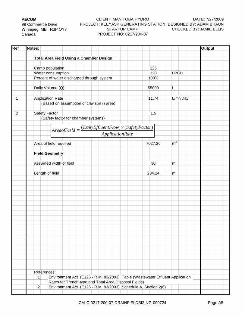
Total Area Field Using a Chamber Design
Camp populationWater consumption LPCDPercent of water discharged through system
Daily Volume (Q) L
1 Application Rate L/m2/Day(Based on assumption of clay soil in area)
2 Safety Factor(Safety factor for chamber systems)
Area of field required m2
Field Geometry
Assumed width of field m
Length of field m
References:1
2 Environment Act (E125 - R.M. 83/2003), Schedule A, Section 2(6)
234.24
30
Environment Act (E125 - R.M. 83/2003), Table (Wastewater Effluent ApplicationRates for Trench-type and Total Area Disposal Fields)
1.5
7027.26
11.74
125320
100%
55000
nRateApplicatioorSafetyFactentFlowDailyEffludAreaofFiel )()( ×
=
CALC-0217-200-07-DRAINFIELDSIZING-090724 Page A5
AECOM99 Commerce DriveWinnipeg, MB R3P OY7Canada
CLIENT: MANITOBA HYDROPROJECT: KEEYASK GENERATING STATION
STARTUP CAMPPROJECT NO: 0217-200-07
DATE: 7/27/2009DESIGNED BY: ADAM BRAUN
CHECKED BY: JAMIE ELLIS
Ref Notes: Output
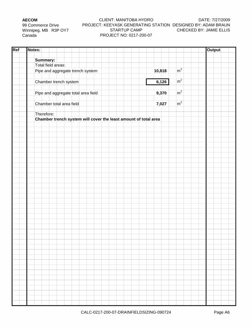
Summary:Total field areas:Pipe and aggregate trench system m2
Chamber trench system m2
Pipe and aggregate total area field m2
Chamber total area field m2
Therefore:Chamber trench system will cover the least amount of total area
10,818
6,126
9,370
7,027
CALC-0217-200-07-DRAINFIELDSIZING-090724 Page A6
PLANSCALE 1:5000m
Figure 1
AE
CO
M F
ILE
NAM
E:IS
S/R
EV:
© 2
009
AEC
OM
Can
ada
Ltd.
All
Rig
hts
Res
erve
d. T
his
docu
men
t is
pro
tect
ed b
y co
pyrig
ht l
aw a
nd m
ay n
ot b
e us
ed, r
epro
duce
d or
mod
ified
in a
ny m
anne
r or
for
any
purp
ose
exce
pt w
ith th
e w
ritte
n pe
rmis
sion
of A
ECO
M C
anad
a Lt
d. (
“AEC
OM
”) or
a p
arty
to w
hich
its
copy
right
has
bee
n as
sign
ed.
AEC
OM
acce
pts
no re
spon
sibi
lity,
and
den
ies
any
liabi
lity
wha
tsoe
ver,
to a
ny p
arty
that
use
s, re
prod
uces
, mod
ifies
, or r
elie
s on
this
doc
umen
t with
out A
ECO
M's
exp
ress
writ
ten
cons
ent.
A
LOCATION PLAN
North Access Road Startup Camp - 243981-0100Keeyask Generating Station - Infrastructure Eng
0217
-200
-07_
01-C
-F00
1_R
X.d
wg
Sav
ed B
y: b
erar
dk
SITE PLANSCALE 1:2500m
Figure 2
AE
CO
M F
ILE
NAM
E:IS
S/R
EV:
© 2
009
AEC
OM
Can
ada
Ltd.
All
Rig
hts
Res
erve
d. T
his
docu
men
t is
prot
ecte
d by
cop
yrig
ht la
w a
nd m
ay n
ot b
e us
ed, r
epro
duce
d or
mod
ified
in a
ny m
anne
r or f
or a
ny p
urpo
se e
xcep
t with
the
writ
ten
perm
issi
on o
f AEC
OM
Can
ada
Ltd.
(“A
ECO
M”)
or a
par
ty to
whi
ch it
s co
pyrig
ht h
as b
een
assi
gned
. AEC
OM
acce
pts
no re
spon
sibi
lity,
and
den
ies
any
liabi
lity
wha
tsoe
ver,
to a
ny p
arty
that
use
s, re
prod
uces
, mod
ifies
, or r
elie
s on
this
doc
umen
t with
out A
ECO
M's
exp
ress
writ
ten
cons
ent.
A
TEST HOLE LOCATION PLAN
North Access Road Startup Camp - 243981-0100Keeyask Generating Station - Infrastructure Eng
Manitoba Hydro
0217
-200
-07_
01-C
-F00
2_R
X.d
wg
Sav
ed B
y: b
erar
dk
GROUND WATER TABLE
Figure 3
AE
CO
M F
ILE
NAM
E:IS
S/R
EV:
© 2
009
AEC
OM
Can
ada
Ltd.
All
Rig
hts
Res
erve
d. T
his
docu
men
t is
pro
tect
ed b
y co
pyrig
ht l
aw a
nd m
ay n
ot b
e us
ed, r
epro
duce
d or
mod
ified
in a
ny m
anne
r or
for
any
purp
ose
exce
pt w
ith th
e w
ritte
n pe
rmis
sion
of A
ECO
M C
anad
a Lt
d. (
“AEC
OM
”) or
a p
arty
to w
hich
its
copy
right
has
bee
n as
sign
ed.
AEC
OM
acce
pts
no re
spon
sibi
lity,
and
den
ies
any
liabi
lity
wha
tsoe
ver,
to a
ny p
arty
that
use
s, re
prod
uces
, mod
ifies
, or r
elie
s on
this
doc
umen
t with
out A
ECO
M's
exp
ress
writ
ten
cons
ent.
A
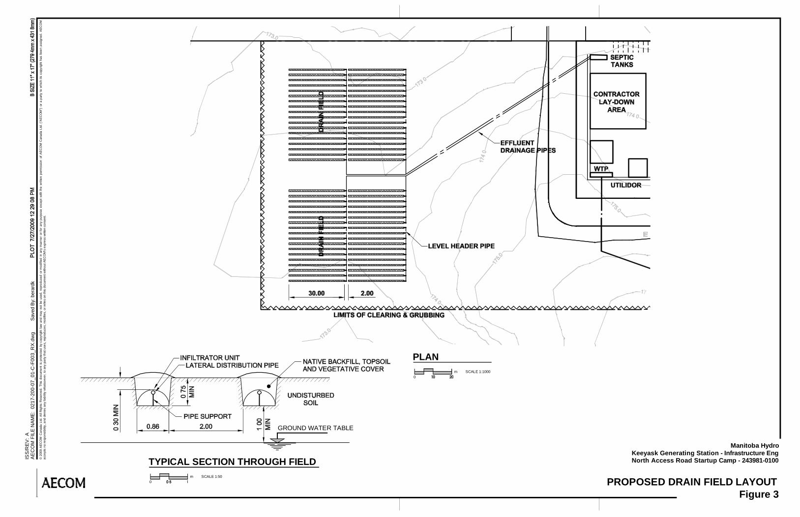
PROPOSED DRAIN FIELD LAYOUT
North Access Road Startup Camp - 243981-0100Keeyask Generating Station - Infrastructure Eng
Manitoba Hydro
0217
-200
-07_
01-C
-F00
3_R
X.d
wg
Sav
ed B
y: b
erar
dk
0
PLANSCALE 1:1000m
0
TYPICAL SECTION THROUGH FIELDSCALE 1:50m

Keeyask Infrastructure Appendix A2 Environmental Assessment
Appendix A2
Analysis of Alternatives

Keeyask Infrastructure Appendix A2 Environmental Assessment
ROAD
Alignment of the proposed road involved a scoping process from selection of a preferred corridor based on a regional analysis to selection of a preferred alignment within the preferred corridor. The regional analysis involved gathering information on the physiography, topography, geology, soils, and broad environmental constraints. Technical feasibility, life-cycle costs, distance to borrow sources and environmental factors were used in the analysis. The Gull Esker provided technical and cost benefits for a corridor and appeared to avoid sensitive areas. Once a preferred corridor was selected, work began on selecting a preferred alignment within the corridor. There will be a 100-m right-of-way (ROW) for the road and the centreline will vary within the 100-m ROW zone. The selection process generally followed five steps. The first step in this process involved the establishment of the North Access Road Route Selection Committee in July 2005 (described further in Section 4.1.1. of the main report), comprised of members of Manitoba Hydro and their consultants, along with representatives from the local potentially affected First Nation communities of Fox Lake Cree Nation, Tataskweyak Cree Nation, York Factory First Nation, War Lake Cree Nation and Manitoba Infrastructure and Transportation. The second step involved the assessment of alternative routes based on a benefit/cost analysis and aerial photograph interpretation. In this analysis, two alternatives were developed along a common roadway alignment while a third alternative was developed along a different roadway alignment. Efforts were made to follow an existing winter trail route which already had received some disturbance. The third step in the process involved field studies to evaluate the alternative alignments. Manitoba Hydro conducted a field program in the winter of 2007-08 for the purpose of collecting data for use in the detailed design stage of the proposed road. The field program involved analyses of the preferred road options using input from technical specialists (including over-flights and ground-based environmental investigations for potential routes) and consultation with the North Access Road Route Selection Committee. In addition, the Committee members were given the opportunity to fly over the proposed route and if necessary, suggest alternative alignments. The fourth step in the process involved the development of constraint mapping on aspects such as fisheries, heritage resources potential, bird nesting and/or concentration areas, rare or uncommon habitat, wetlands and organic soils with excessive ice, potential bear dens, caribou calving, enduring physical features, etc., as well as maps of local First Nations’ sensitivities such as resource harvesting trails and traplines. The output was used to identify environmental sensitivities within the proposed route alignments and to establish mitigation measures and/or alignment adjustments for protection of identified environmental considerations. An analysis of the constraint mapping allowed for alignment adjustments to avoid sensitive areas. Integrated with the previous analyses, the process enabled the selection of a preferred alignment based on the following factors:
Keeyask Infrastructure Appendix A2 Environmental Assessment
• Minimizing potential adverse effects to the environment; • Remaining cost-effective and provide good technical potential for a safe route design; and • Minimizing construction schedule risks. A final step in the process was a series of public meetings in local First Nation communities (Bird, Gillam and Ilford) to present the road and gather feedback on the preferred route alignment. This is described in Section 4.1.1 of the main text. The preferred alignment allows for borrow material for the road to be obtained from within the ROW instead of distant borrow pits. There is an existing borrow pit near the junction of PR 280 and the road, which may be used along with material from the G-3 deposit, but overall, material for the road will be taken from within the 100-m ROW. STARTUP CAMP WASTEWATER TREATMENT
As described in the Concept Design (Appendix A1), a range of alternatives was considered for sanitary wastewater disposal at the start-up camp, including hauling black water or sewage to Split Lake, Gillam or Thompson, a mechanical treatment plant, a holding tank with a drain or septic field, and a sewage lagoon. The alternatives were evaluated from monetary and non-monetary aspects, such as potential for disruption (bad weather, freezing conditions) and training requirements. The wastewater lagoon at Split Lake is already overloaded. Hauling wastewater to Gillam or Thompson presents risk due to inclement weather, would be costly, and consume a large amount of fuel. A mechanical plant would require trained operators and an adsorption field, as there is no adequate receiving stream nearly the site. A wastewater lagoon would be feasible but is high in cost. The septic tank/field option was identified as the preferred alternative for reasons of cost, relatively low risk, and reliability. Preliminary information on site conditions indicates that the soil is likely suitable for a disposal field and, accordingly, the septic tank/field option is planned. Further geotechnical investigations are underway to confirm the suitability of the soil conditions. In the event that this information does not confirm the appropriateness of this option, the alternatives of a mechanical plant with an adsorption field or hauling of the wastewater to Gillam will be proposed.
STARTUP CAMP
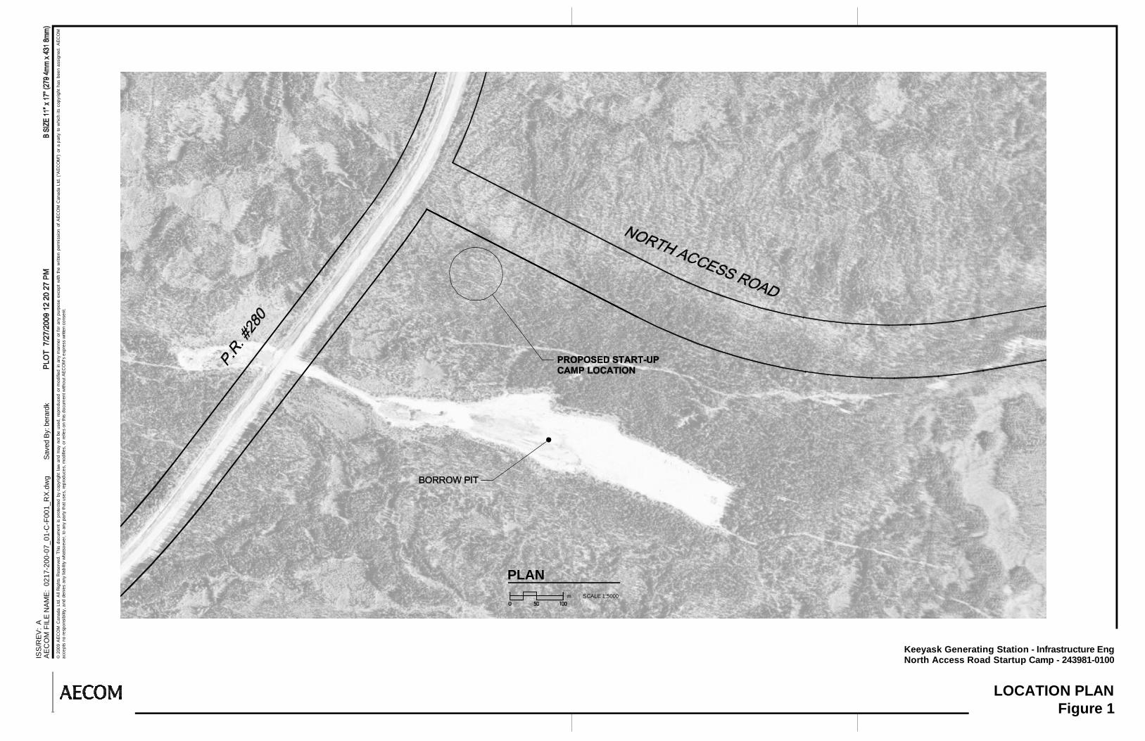
The presence of an existing disturbed area near the beginning of the proposed road corridor provided the basis for selecting the start-up camp location. Conditions that favoured this location included distance from PR 280, raised elevation, presence of treed buffer area, proximity to a potential potable water source, and site drainage away from water source. A location away from PR 280, but close enough to allow ready access to this existing road was a major factor in site selection.
Keeyask Infrastructure Appendix A2 Environmental Assessment
MAIN CAMP (PHASE ONE)
The location of the main camp for the proposed Keeyask GS project was determined relative to the location of the GS facilities, and considered access to the site and suitability of site conditions. Distance from the GS site was considered to be a critical factor in location. Favourable conditions also included relatively level land surface, foundation type, site drainage, avoidance of wetlands, proximity of granular sources, potable water supply and waste disposal opportunities.
STREAM CROSSING
Three main alternatives were considered for the crossing at Looking Back Creek. The alternatives included a multi-plate culvert, a bridge with abutments and a clear-span bridge. The preferred alternative was the clear-span bridge due to the minimal risk of adverse effects on fish and fish habitat, despite the comparatively higher cost. The selected crossing location was determined to be more favourable than upstream and downstream locations where the creek was either wider or not confined to a channel. No alternatives were considered for the crossing at the unnamed tributary, due to the low sensitivity of the site.
BORROW AREAS
Borrow areas, including granular sources, in the Local Study Area were identified from previous investigations by Manitoba Hydro along the Nelson River. From among the sources available, borrow areas for road construction, camp development and other infrastructure were selected based on their distance from the construction activity and characteristics of the borrow materials. From among a group that appeared to be economically feasible to use, environmental input was provided to determine sensitivities. In general it was decided to remain within the defined ROW as much as possible.
POTABLE WATER SUPPLY
Potable water supply alternatives for the start-up camp were to haul in water from Gillam or Thompson and to use local well water. Use of a proposed well in the vicinity of the start-up camp was preferred on the basis of cost, supply sustainability and environmental considerations.

Keeyask Infrastructure Appendix A2 Environmental Assessment
A2-1
Appendix A3
Contracts and Workforce Requirements
Keeyask Infrastructure Appendix A3 Environmental Assessment
A3-1
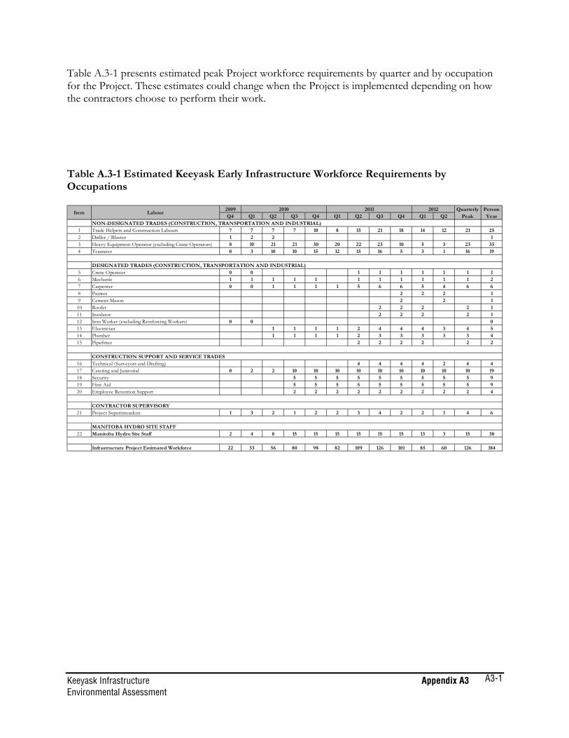
Table A.3-1 presents estimated peak Project workforce requirements by quarter and by occupation for the Project. These estimates could change when the Project is implemented depending on how the contractors choose to perform their work. Table A.3-1 Estimated Keeyask Early Infrastructure Workforce Requirements by Occupations
2009 2010 2011 2012Q4 Q1 Q2 Q3 Q4 Q1 Q2 Q3 Q4 Q1 Q2
NON-DESIGNATED TRADES (CONSTRUCTION, TRANSPORTATION AND INDUSTRIAL)1 Trade Helpers and Construction Labours 7 7 7 7 10 8 15 21 18 14 12 21 252 Driller / Blaster 1 2 2 13 Heavy Equipment Operator (excluding Crane Operators) 8 10 21 21 30 20 22 23 10 5 3 23 354 Teamster 0 3 10 10 15 12 15 16 5 3 1 16 19
DESIGNATED TRADES (CONSTRUCTION, TRANSPORTATION AND INDUSTRIAL)5 Crane Operator 0 0 1 1 1 1 1 1 16 Mechanic 1 1 1 1 1 1 1 1 1 1 1 27 Carpenter 0 0 1 1 1 1 5 6 6 5 4 6 68 Painter 2 2 2 19 Cement Mason 2 2 1
10 Roofer 2 2 2 2 111 Insulator 2 2 2 2 112 Iron Worker (excluding Reinforcing Workers) 0 0 013 Electrician 1 1 1 1 2 4 4 4 3 4 514 Plumber 1 1 1 1 2 3 3 3 3 3 415 Pipefitter 2 2 2 2 2 2
CONSTRUCTION SUPPORT AND SERVICE TRADES16 Technical (Surveyors and Drafting) 4 4 4 4 2 4 417 Catering and Janitorial 0 2 2 10 10 10 10 10 10 10 10 10 1918 Security 5 5 5 5 5 5 5 5 5 919 First Aid 5 5 5 5 5 5 5 5 5 920 Employee Retention Support 2 2 2 2 2 2 2 2 2 4
CONTRACTOR SUPERVISORY 21 Project Superintendent 1 3 2 1 2 2 3 4 2 2 1 4 6
MANITOBA HYDRO SITE STAFF22 Manitoba Hydro Site Staff 2 4 8 15 15 15 15 15 15 13 3 15 30
Infrastructure Project Estimated Workforce 22 33 56 80 98 82 109 126 101 85 60 126 184
Item LabourQuarterly
Peak Person
Year