Embed Size (px)
Citation preview
Joseph Sharkey 51 Final Report Spring 2007
AAppppeennddiixx AA SShheeaarr WWaallll DDeessiiggnn
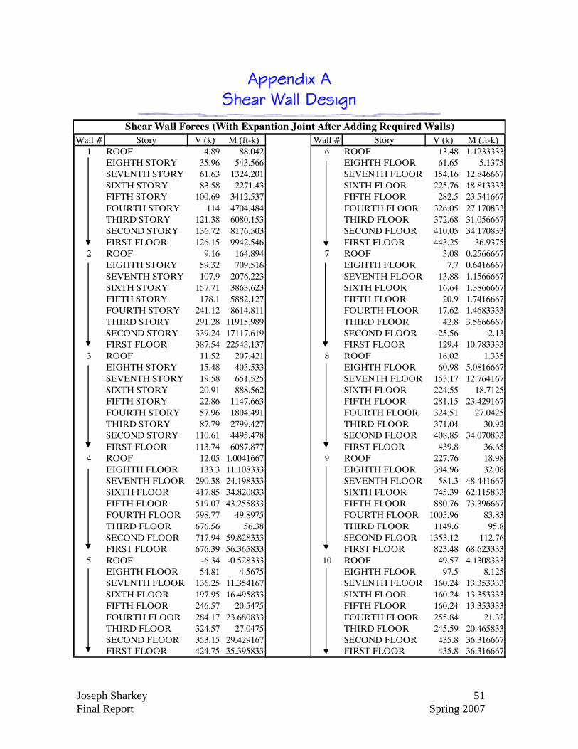
Wall # Story V (k) M (ft-k) Wall # Story V (k) M (ft-k)1 ROOF 4.89 88.042 6 ROOF 13.48 1.1233333
EIGHTH STORY 35.96 543.566 EIGHTH FLOOR 61.65 5.1375SEVENTH STORY 61.63 1324.201 SEVENTH FLOOR 154.16 12.846667SIXTH STORY 83.58 2271.43 SIXTH FLOOR 225.76 18.813333FIFTH STORY 100.69 3412.537 FIFTH FLOOR 282.5 23.541667FOURTH STORY 114 4704.484 FOURTH FLOOR 326.05 27.170833THIRD STORY 121.38 6080.153 THIRD FLOOR 372.68 31.056667SECOND STORY 136.72 8176.503 SECOND FLOOR 410.05 34.170833FIRST FLOOR 126.15 9942.546 FIRST FLOOR 443.25 36.9375
2 ROOF 9.16 164.894 7 ROOF 3.08 0.2566667EIGHTH STORY 59.32 709.516 EIGHTH FLOOR 7.7 0.6416667SEVENTH STORY 107.9 2076.223 SEVENTH FLOOR 13.88 1.1566667SIXTH STORY 157.71 3863.623 SIXTH FLOOR 16.64 1.3866667FIFTH STORY 178.1 5882.127 FIFTH FLOOR 20.9 1.7416667FOURTH STORY 241.12 8614.811 FOURTH FLOOR 17.62 1.4683333THIRD STORY 291.28 11915.989 THIRD FLOOR 42.8 3.5666667SECOND STORY 339.24 17117.619 SECOND FLOOR -25.56 -2.13FIRST FLOOR 387.54 22543.137 FIRST FLOOR 129.4 10.783333
3 ROOF 11.52 207.421 8 ROOF 16.02 1.335EIGHTH STORY 15.48 403.533 EIGHTH FLOOR 60.98 5.0816667SEVENTH STORY 19.58 651.525 SEVENTH FLOOR 153.17 12.764167SIXTH STORY 20.91 888.562 SIXTH FLOOR 224.55 18.7125FIFTH STORY 22.86 1147.663 FIFTH FLOOR 281.15 23.429167FOURTH STORY 57.96 1804.491 FOURTH FLOOR 324.51 27.0425THIRD STORY 87.79 2799.427 THIRD FLOOR 371.04 30.92SECOND STORY 110.61 4495.478 SECOND FLOOR 408.85 34.070833FIRST FLOOR 113.74 6087.877 FIRST FLOOR 439.8 36.65
4 ROOF 12.05 1.0041667 9 ROOF 227.76 18.98EIGHTH FLOOR 133.3 11.108333 EIGHTH FLOOR 384.96 32.08SEVENTH FLOOR 290.38 24.198333 SEVENTH FLOOR 581.3 48.441667SIXTH FLOOR 417.85 34.820833 SIXTH FLOOR 745.39 62.115833FIFTH FLOOR 519.07 43.255833 FIFTH FLOOR 880.76 73.396667FOURTH FLOOR 598.77 49.8975 FOURTH FLOOR 1005.96 83.83THIRD FLOOR 676.56 56.38 THIRD FLOOR 1149.6 95.8SECOND FLOOR 717.94 59.828333 SECOND FLOOR 1353.12 112.76FIRST FLOOR 676.39 56.365833 FIRST FLOOR 823.48 68.623333
5 ROOF -6.34 -0.528333 10 ROOF 49.57 4.1308333EIGHTH FLOOR 54.81 4.5675 EIGHTH FLOOR 97.5 8.125SEVENTH FLOOR 136.25 11.354167 SEVENTH FLOOR 160.24 13.353333SIXTH FLOOR 197.95 16.495833 SIXTH FLOOR 160.24 13.353333FIFTH FLOOR 246.57 20.5475 FIFTH FLOOR 160.24 13.353333FOURTH FLOOR 284.17 23.680833 FOURTH FLOOR 255.84 21.32THIRD FLOOR 324.57 27.0475 THIRD FLOOR 245.59 20.465833SECOND FLOOR 353.15 29.429167 SECOND FLOOR 435.8 36.316667FIRST FLOOR 424.75 35.395833 FIRST FLOOR 435.8 36.316667
Shear Wall Forces (With Expantion Joint After Adding Required Walls)

Joseph Sharkey 52 Final Report Spring 2007
Wall # Story V (k) M (ft-k) Wall # Story V (k) M (ft-k)11 ROOF 119.39 9.949167 15 ROOF 8.5 153.026
EIGHTH FLOOR 181.5 15.125 EIGHTH STORY 10.87 290.756SEVENTH FLOOR 271.17 22.5975 SEVENTH STORY 13.53 462.088SIXTH FLOOR 344.35 28.69583 SIXTH STORY 14.03 621.061FIFTH FLOOR 399.47 33.28917 FIFTH STORY 13.8 777.498FOURTH FLOOR 430.97 35.91417 FOURTH STORY 41.45 1247.234THIRD FLOOR 439.81 36.65083 THIRD STORY 64.24 1975.336SECOND FLOOR 429.53 35.79417 SECOND STORY 79.16 3189.1FIRST FLOOR 407.37 33.9475 FIRST FLOOR 92.19 4479.733
12 ROOF 57.71 4.809167 16 ROOF 3.12 56.158EIGHTH FLOOR 113.94 9.495 EIGHTH STORY 26.05 56.158SEVENTH FLOOR 184.94 15.41167 SEVENTH STORY 44.22 386.133SIXTH FLOOR 237.68 19.80667 SIXTH STORY 59.9 946.307FIFTH FLOOR 276.52 23.04333 FIFTH STORY 72.07 1625.211FOURTH FLOOR 306.17 25.51417 FOURTH STORY 82.2 2442.044THIRD FLOOR 290.58 24.215 THIRD STORY 90.94 3373.646SECOND FLOOR 276.93 23.0775 SECOND STORY 93.09 4404.259FIRST FLOOR 497.58 41.465 FIRST FLOOR 109.65 5831.622
13 ROOF 58.26 4.855 17 ROOF -31.25 -472.522EIGHTH FLOOR 109.09 9.090833 EIGHTH STORY -54.63 -863.06SEVENTH FLOOR 178.14 14.845 SEVENTH STORY -74.06 -1256.55SIXTH FLOOR 238.08 19.84 SIXTH STORY -82.04 -1491.19FIFTH FLOOR 285.55 23.79583 FIFTH STORY -107.3 -1859.8FOURTH FLOOR 318.2 26.51667 FOURTH STORY -132.9 -2296.84THIRD FLOOR 339.2 28.26667 THIRD STORY -153.8 -2800.75SECOND FLOOR 309.16 25.76333 SECOND STORY -161.1 -3555.13FIRST FLOOR 268.36 22.36333 FIRST FLOOR -160.9 -3677.9
14 ROOF -90.81 -7.5675 18 ROOF -1.11 39.706EIGHTH FLOOR 77.04 6.42 EIGHTH STORY 25.76 255.609SEVENTH FLOOR 143.39 11.94917 SEVENTH STORY 44.1 677.067SIXTH FLOOR 196.43 16.36917 SIXTH STORY 61.4 1187.429FIFTH FLOOR 239.02 19.91833 FIFTH STORY 77.8 1835.307FOURTH FLOOR 267.47 22.28917 FOURTH STORY 80.38 2451.4THIRD FLOOR 287.89 23.99083 THIRD STORY 80.72 3015.326SECOND FLOOR 302.01 25.1675 SECOND STORY 89.53 3907.391FIRST FLOOR 342.37 28.53083 FIRST FLOOR 93.02 4605.752
Shear Wall Forces (With Expantion Joint After Adding Required Walls)

Joseph Sharkey 53 Final Report Spring 2007
Wall # Story V (k) M (ft-k)19 SECOND STORY 30.7 552.57
FIRST FLOOR 105.9 2035.15320 THIRD STORY 36.34 401.063
SECOND STORY 81.17 1383.472FIRST FLOOR 133.52 2457.171
21 THIRD STORY 86.49 673.003SECOND STORY 134.03 1485.795FIRST FLOOR 150.91 1780.027
22 THIRD STORY -64.42 -522.838SECOND STORY -76.77 -1354.448FIRST FLOOR -132.26 -2492.499
23 THIRD STORY 51.46 536.867SECOND STORY 127.4 2046.526FIRST FLOOR 187.63 3618.693
24 THIRD STORY 15.01 113.387SECOND STORY 32.8 306.455FIRST FLOOR 53.76 673.614
25 THIRD STORY 91.48 1311.237SECOND STORY 170.72 4384.221FIRST FLOOR 229.98 7603.877
26 THIRD STORY 105.41 1510.87SECOND STORY 177.75 4710.306FIRST FLOOR 241.47 8090.857
27 THIRD STORY 138.88 1990.617SECOND STORY 227.89 6092.708FIRST FLOOR 348.38 10969.995
Shear Wall Forces (Post-Tensioned Conference Wing)

Joseph Sharkey 54 Final Report Spring 2007
1 2 3 4 5 6 7 8Length 11.7 18.5 11.7 23.5 18.58 19.7 8.75 19.7
Boundary Element
T.1-59, T.1-61 T.1-59, U.1-59 U.1-59,U.1-61 U.66 U-69 U-71 U-71, U-72 T-72
8 #5@18" #5@18" #5@18" #5@18" #5@18" #5@18" #5@18"7 #5@18"65432 #5@16"1G
9 10 11 12 13 14 15 16Length 26.2 18.5 20.67 18.5 9 20.67 11.4 11.4
Boundary Element
S-72 Q-71 N-71 R-71 N-71, M-71 M-71 U.1-63, U.1-65 T.1-63, T.1-65
8 #5@18" #5@18" #5@18" #5@18" #5@18" #5@18"7 #5@14" #5@18"654 #5@10"32 #5@16"1G
Floor
Floor
12" Concrete Shear Wall Schedule
12" Concrete Shear Wall Schedule
Joseph Sharkey 55 Final Report Spring 2007
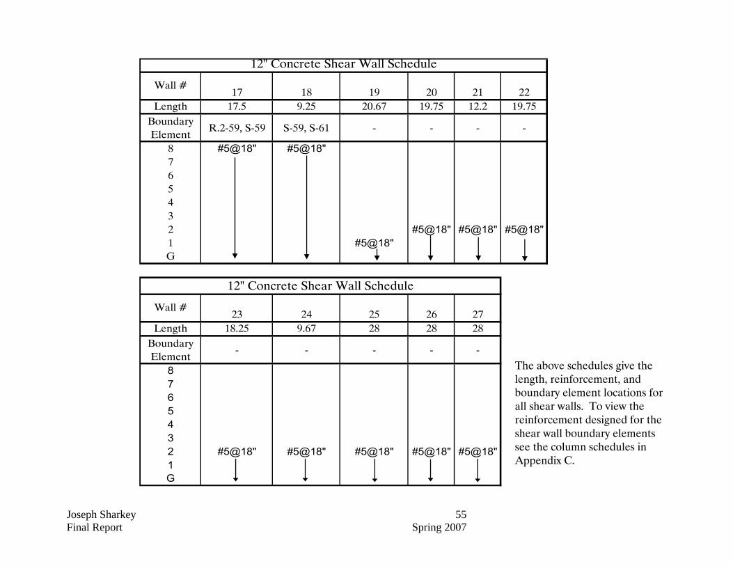
17 18 19 20 21 22Length 17.5 9.25 20.67 19.75 12.2 19.75
Boundary Element
R.2-59, S-59 S-59, S-61 - - - -
8 #5@18" #5@18"765432 #5@18" #5@18" #5@18"1 #5@18"G
23 24 25 26 27Length 18.25 9.67 28 28 28
Boundary Element
- - - - -
8765432 #5@18" #5@18" #5@18" #5@18" #5@18"1G
Wall #
12" Concrete Shear Wall Schedule
Wall #
12" Concrete Shear Wall Schedule
The above schedules give the length, reinforcement, and boundary element locations for all shear walls. To view the reinforcement designed for the shear wall boundary elements see the column schedules in Appendix C.

Joseph Sharkey 56 Final Report Spring 2007
Engineer: Joe SharkeyDate: 3/19/2007Job: Christiana Hospital ProjectShear Wall # 1 - Ground Floor through 2nd
Concrete Strength - f'c (psi) = 5000Reinforcement Strength - fy (psi) = 60000
Length - d (ft) = 11.7Width - w (in) = 16Height - h (ft) = 118
Length - dbe (in) = 18Width - wbe (in) = 18
Pu (kip) = 813Mu (ft-kip) = 9943
Vu (kip) = 126
Axial Force - Pube (kip) = 1256.329
ACI 21.7.6.3Ag (ft2) = 17.6Ig (in4) = 255.552
Extreme Fiber Comp. - Fc (ksi) = 2.104066 Boundary Elemement Needed - fc>0.2 f'c
Shear Wall Design
Material Properties
Wall Dimensions
Boundary Element Dimensions
Wall Loads
Boundary Element
Boundary Element Check
d
dbe
h
wbe
w
Pu
Vu
Mu
Joseph Sharkey 57 Final Report Spring 2007
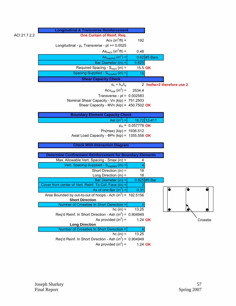
ACI 21.7.2.2 One Curtain of Reinf. Req.Acv (in2/ft) = 192
Longitudinal - ρl, Transverse - ρt >= 0.0025Aslreq'd (in
2/ft) = 0.48Assupplied (in
2) = 0.62 #5 BarsBar Diameter (in) = 0.625
Required Spacing - Sreq'd (in) = 15.5Spacing Supplied - Ssupplied (in) = 15
αc = hw/lw 2Acvtotal (in
2) = 2534.4Transverse - ρt = 0.002583
Nominal Shear Capacity - Vn (kip) = 751.2503Shear Capacity - ФVn (kip) = 450.7502
Ast (in2) = 18.72 12-#11ρst = 0.057778
Pn(max) (kip) = 1936.512Axial Load Capacity - ФPn (kip) = 1355.558
Max. Allowable Vert. Spacing - Smax (in) = 4Vert. Spacing Supplied - Ssupplied (in) = 4
Short Direction (in) = 18Long Direction (in) = 18
Bar Diameter (in) = 0.625 #5 BarCover from center of Vert. Reinf. To Col. Face (in) = 3
As of one Bar (in2) = 0.31Area Bounded by out-to-out of hoops - Ach (in2) = 192.5156
Short DirectionNumber of Crossties In Short Derection = 4
hc (in) = 13.25Req'd Reinf. In Short Direction - Ash (in2) = 0.904949
As provided (in2) = 1.24 OKLong Direction
Number of Crossties In Short Derection = 4hc (in) = 13.25
Req'd Reinf. In Short Direction - Ash (in2) = 0.904949As provided (in2) = 1.24 OK
Longitudinal & Transverse Reinforcement
Determine Confinement Reinforcement for Boundary Elements
OK
Shear Capacity Check hw/lw>2 therefore use 2
OK
Boundary Element Capacity Check
OK
OK
Check With Interaction Diagram
Crosstie

Joseph Sharkey 58 Final Report Spring 2007
Engineer: Joe SharkeyDate: 3/19/2007Job: Christiana Hospital ProjectShear Wall # 1 - 3rd through 8th
Concrete Strength - f'c (psi) = 4000Reinforcement Strength - fy (psi) = 60000
Length - d (ft) = 11.7Width - w (in) = 12Height - h (ft) = 118
Length - dbe (in) = 18Width - wbe (in) = 18
Pu (kip) = 586Mu (ft-kip) = 4704
Vu (kip) = 114
Axial Force - Pube (kip) = 695.0513
ACI 21.7.6.3Ag (ft2) = 13.2Ig (in4) = 191.664
Extreme Fiber Comp. - Fc (ksi) = 1.433176 Boundary Elemement Needed - fc>0.2 f'c
Shear Wall Design
Material Properties
Wall Dimensions
Boundary Element Dimensions
Wall Loads
Boundary Element
Boundary Element Check
d
dbe
h
wbe
w
Pu
Vu
Mu

Joseph Sharkey 59 Final Report Spring 2007
ACI 21.7.2.2 One Curtain of Reinf. Req.Acv (in2/ft) = 144
Longitudinal - ρl, Transverse - ρt >= 0.0025Aslreq'd (in
2/ft) = 0.36Assupplied (in
2) = 0.62 #5 BarsBar Diameter (in) = 0.625
Required Spacing - Sreq'd (in) = 20.66667Spacing Supplied - Ssupplied (in) = 18
αc = hw/lw 2Acvtotal (in
2) = 1900.8Transverse - ρt = 0.00287
Nominal Shear Capacity - Vn (kip) = 567.7943Shear Capacity - ФVn (kip) = 340.6766
Ast (in2) = 6.24 4-#11ρst = 0.019259
Pn(max) (kip) = 1163.827Axial Load Capacity - ФPn (kip) = 814.679
Max. Allowable Vert. Spacing - Smax (in) = 4Vert. Spacing Supplied - Ssupplied (in) = 4
Short Direction (in) = 18Long Direction (in) = 18
Bar Diameter (in) = 0.625 #5 BarCover from center of Vert. Reinf. To Col. Face (in) = 3
As of one Bar (in2) = 0.31Area Bounded by out-to-out of hoops - Ach (in2) = 192.5156
Short DirectionNumber of Crossties In Short Derection = 3
hc (in) = 13.25Req'd Reinf. In Short Direction - Ash (in2) = 0.723959
As provided (in2) = 0.93 OKLong Direction
Number of Crossties In Short Derection = 3hc (in) = 13.25
Req'd Reinf. In Short Direction - Ash (in2) = 0.723959As provided (in2) = 0.93 OK
Longitudinal & Transverse Reinforcement
Determine Confinement Reinforcement for Boundary Elements
NOT OK Spacing Must Be Less Than 18in
Shear Capacity Check hw/lw>2 therefore use 2
OK
Boundary Element Capacity Check
OK
OK
Check With Interaction Diagram
CrosstieCrosstie

Joseph Sharkey 60 Final Report Spring 2007
Engineer: Joe SharkeyDate: 3/19/2007Job: Christiana Hospital ProjectShear Wall # 5 - Ground Floor through 2nd
Concrete Strength - f'c (psi) = 5000Reinforcement Strength - fy (psi) = 60000
Length - d (ft) = 18.58Width - w (in) = 12Height - h (ft) = 118
Length - dbe (in) = 30Width - wbe (in) = 30
Pu (kip) = 2253Mu (ft-kip) = 25605
Vu (kip) = 425
Axial Force - Pube (kip) = 2504.595
ACI 21.7.6.3Ag (ft2) = 21.08Ig (in4) = 780.6036
Extreme Fiber Comp. - Fc (ksi) = 3.143103 Boundary Elemement Needed - fc>0.2 f'c
Shear Wall Design
Material Properties
Wall Dimensions
Boundary Element Dimensions
Wall Loads
Boundary Element
Boundary Element Check
d
dbe
h
wbe
w
Pu
Vu
Mu

Joseph Sharkey 61 Final Report Spring 2007
ACI 21.7.2.2 One Curtain of Reinf. Req.Acv (in2/ft) = 144
Longitudinal - ρl, Transverse - ρt >= 0.0025Aslreq'd (in
2/ft) = 0.36Assupplied (in
2) = 0.62 #5 BarsBar Diameter (in) = 0.625
Required Spacing - Sreq'd (in) = 20.66667Spacing Supplied - Ssupplied (in) = 18
αc = hw/lw 2Acvtotal (in
2) = 3035.52Transverse - ρt = 0.00287
Nominal Shear Capacity - Vn (kip) = 952.0714Shear Capacity - ФVn (kip) = 571.2428
Ast (in2) = 12.48 8-#11ρst = 0.013867
Pn(max) (kip) = 3616.608Axial Load Capacity - ФPn (kip) = 2531.626
Max. Allowable Vert. Spacing - Smax (in) = 4Vert. Spacing Supplied - Ssupplied (in) = 4
Short Direction (in) = 30Long Direction (in) = 30
Bar Diameter (in) = 0.625 #5 BarCover from center of Vert. Reinf. To Col. Face (in) = 3
As of one Bar (in2) = 0.31Area Bounded by out-to-out of hoops - Ach (in2) = 669.5156
Short DirectionNumber of Crossties In Short Direction = 3
hc (in) = 25.25Req'd Reinf. In Short Direction - Ash (in2) = 0.869245
As provided (in2) = 0.93 OKLong Direction
Number of Crossties In Short Direction = 3hc (in) = 25.25
Req'd Reinf. In Short Direction - Ash (in2) = 0.869245As provided (in2) = 0.93 OK
Longitudinal & Transverse Reinforcement
Determine Confinement Reinforcement for Boundary Elements
NOT OK Spacing Must Be Less Than 18in
Shear Capacity Check hw/lw>2 therefore use 2
OK
Boundary Element Capacity Check
OK
OK
Check With Interaction Diagram
Crosstie

Joseph Sharkey 62 Final Report Spring 2007
Engineer: Joe SharkeyDate: 3/19/2007Job: Christiana Hospital ProjectShear Wall # 5 - 3rd and 4th Floors
Concrete Strength - f'c (psi) = 4000Reinforcement Strength - fy (psi) = 60000
Length - d (ft) = 18.58Width - w (in) = 12Height - h (ft) = 77.33
Length - dbe (in) = 24Width - wbe (in) = 24
Pu (kip) = 1522Mu (ft-kip) = 10564
Vu (kip) = 284
Axial Force - Pube (kip) = 1329.568
ACI 21.7.6.3Ag (ft2) = 20.58Ig (in4) = 726.3649
Extreme Fiber Comp. - Fc (ksi) = 1.552844 Boundary Elemement Needed - fc>0.2 f'c
Shear Wall Design
Material Properties
Wall Dimensions
Boundary Element Dimensions
Wall Loads
Boundary Element
Boundary Element Check
d
dbe
h
wbe
w
Pu
Vu
Mu

Joseph Sharkey 63 Final Report Spring 2007
ACI 21.7.2.2 One Curtain of Reinf. Req.Acv (in2/ft) = 144
Longitudinal - ρl, Transverse - ρt >= 0.0025Aslreq'd (in
2/ft) = 0.36Assupplied (in
2) = 0.62 #5 BarsBar Diameter (in) = 0.625
Required Spacing - Sreq'd (in) = 20.66667Spacing Supplied - Ssupplied (in) = 18
αc = hw/lw 2Acvtotal (in
2) = 2963.52Transverse - ρt = 0.00287
Nominal Shear Capacity - Vn (kip) = 885.2429Shear Capacity - ФVn (kip) = 531.1458
Ast (in2) = 12.48 8-#11ρst = 0.021667
Pn(max) (kip) = 2131.814Axial Load Capacity - ФPn (kip) = 1492.27
Max. Allowable Vert. Spacing - Smax (in) = 4Vert. Spacing Supplied - Ssupplied (in) = 4
Short Direction (in) = 24Long Direction (in) = 24
Bar Diameter (in) = 0.625 #5 BarCover from center of Vert. Reinf. To Col. Face (in) = 3
As of one Bar (in2) = 0.31Area Bounded by out-to-out of hoops - Ach (in2) = 395.0156
Short DirectionNumber of Crossties In Short Direction = 3
hc (in) = 19.25Req'd Reinf. In Short Direction - Ash (in2) = 0.705582
As provided (in2) = 0.93 OKLong Direction
Number of Crossties In Short Direction = 3hc (in) = 19.25
Req'd Reinf. In Short Direction - Ash (in2) = 0.705582As provided (in2) = 0.93 OK
Longitudinal & Transverse Reinforcement
Determine Confinement Reinforcement for Boundary Elements
NOT OK Spacing Must Be Less Than 18in
Shear Capacity Check hw/lw>2 therefore use 2
OK
Boundary Element Capacity Check
OK
OK
Check With Interaction Diagram
Crosstie

Joseph Sharkey 64 Final Report Spring 2007
Engineer: Joe SharkeyDate: 3/19/2007Job: Christiana Hospital ProjectShear Wall # 5 - 5th through 8th
Concrete Strength - f'c (psi) = 4000Reinforcement Strength - fy (psi) = 60000
Length - d (ft) = 18.58Width - w (in) = 12Height - h (ft) = 77.33
Length - dbe (in) = 24Width - wbe (in) = 24
Pu (kip) = 1080Mu (ft-kip) = 4549
Vu (kip) = 198
Axial Force - Pube (kip) = 784.8332
ACI 21.7.6.3Ag (ft2) = 20.58Ig (in4) = 726.3649
Extreme Fiber Comp. - Fc (ksi) = 0.811953
Wall Loads
Boundary Element
Boundary Element Check
Boundary Elemement Needed - fc>0.2 f'c
Shear Wall Design
Material Properties
Wall Dimensions
Boundary Element Dimensions
d
dbe
h
wbe
w
Pu
Vu
Mu
Joseph Sharkey 65 Final Report Spring 2007
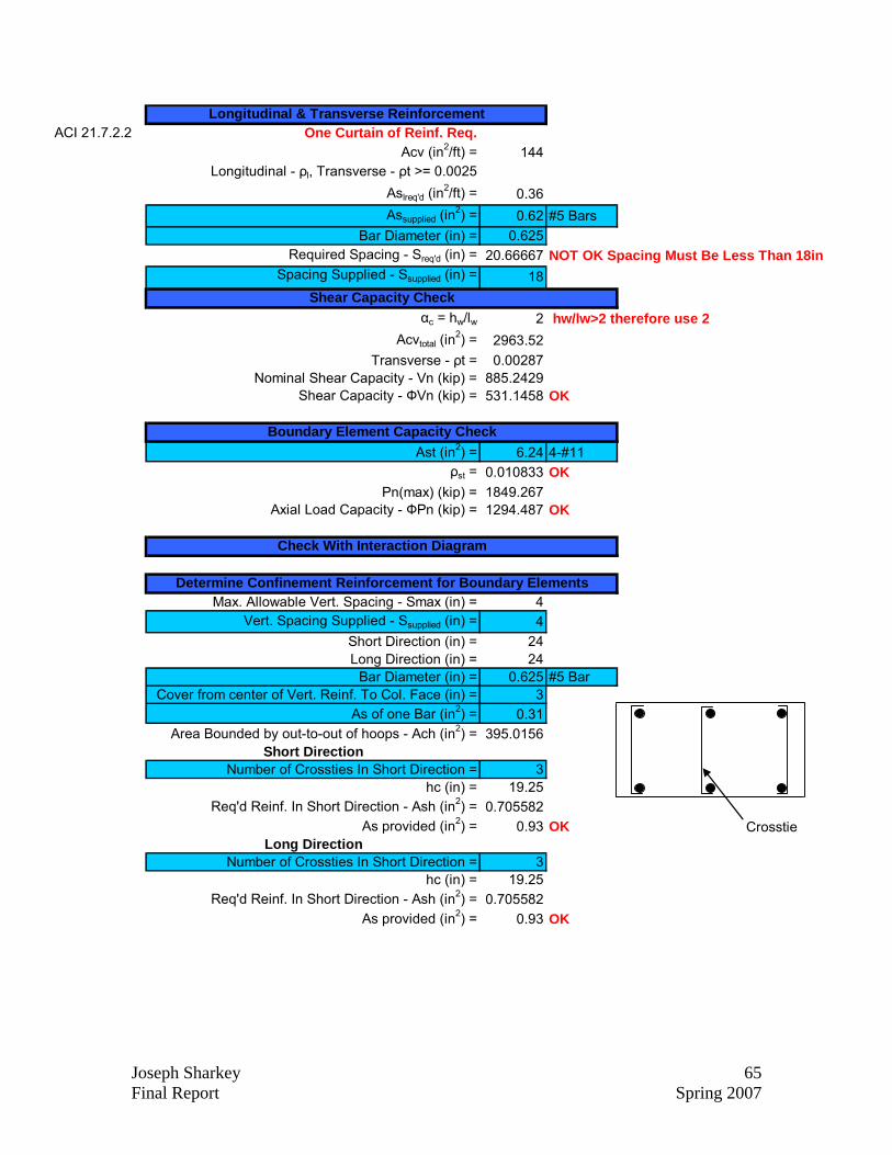
ACI 21.7.2.2 One Curtain of Reinf. Req.Acv (in2/ft) = 144
Longitudinal - ρl, Transverse - ρt >= 0.0025Aslreq'd (in
2/ft) = 0.36Assupplied (in
2) = 0.62 #5 BarsBar Diameter (in) = 0.625
Required Spacing - Sreq'd (in) = 20.66667Spacing Supplied - Ssupplied (in) = 18
αc = hw/lw 2Acvtotal (in
2) = 2963.52Transverse - ρt = 0.00287
Nominal Shear Capacity - Vn (kip) = 885.2429Shear Capacity - ФVn (kip) = 531.1458
Ast (in2) = 6.24 4-#11ρst = 0.010833
Pn(max) (kip) = 1849.267Axial Load Capacity - ФPn (kip) = 1294.487
Max. Allowable Vert. Spacing - Smax (in) = 4Vert. Spacing Supplied - Ssupplied (in) = 4
Short Direction (in) = 24Long Direction (in) = 24
Bar Diameter (in) = 0.625 #5 BarCover from center of Vert. Reinf. To Col. Face (in) = 3
As of one Bar (in2) = 0.31Area Bounded by out-to-out of hoops - Ach (in2) = 395.0156
Short DirectionNumber of Crossties In Short Direction = 3
hc (in) = 19.25Req'd Reinf. In Short Direction - Ash (in2) = 0.705582
As provided (in2) = 0.93 OKLong Direction
Number of Crossties In Short Direction = 3hc (in) = 19.25
Req'd Reinf. In Short Direction - Ash (in2) = 0.705582As provided (in2) = 0.93 OK
Determine Confinement Reinforcement for Boundary Elements
NOT OK Spacing Must Be Less Than 18in
Shear Capacity Check hw/lw>2 therefore use 2
OK
Boundary Element Capacity Check
OK
OK
Check With Interaction Diagram
Longitudinal & Transverse Reinforcement
Crosstie

Joseph Sharkey 66 Final Report Spring 2007
Engineer: Joe SharkeyDate: 3/19/2007Job: Christiana Hospital ProjectShear Wall # 11 - Ground Floor through 2nd
Concrete Strength - f'c (psi) = 5000Reinforcement Strength - fy (psi) = 60000
Length - d (ft) = 20.67Width - w (in) = 12Height - h (ft) = 118
Length - dbe (in) = 24Width - wbe (in) = 24
Pu (kip) = 1745Mu (ft-kip) = 20917
Vu (kip) = 407
Axial Force - Pube (kip) = 1884.45
ACI 21.7.6.3Ag (ft2) = 22.67Ig (in4) = 970.8973
Extreme Fiber Comp. - Fc (ksi) = 2.230382 Boundary Elemement Needed - fc>0.2 f'c
Shear Wall Design
Material Properties
Wall Dimensions
Boundary Element Dimensions
Wall Loads
Boundary Element
Boundary Element Check
d
dbe
h
wbe
w
Pu
Vu
Mu

Joseph Sharkey 67 Final Report Spring 2007
ACI 21.7.2.2 One Curtain of Reinf. Req.Acv (in2/ft) = 144
Longitudinal - ρl, Transverse - ρt >= 0.0025Aslreq'd (in
2/ft) = 0.36Assupplied (in
2) = 0.62 #5 BarsBar Diameter (in) = 0.625
Required Spacing - Sreq'd (in) = 20.66667Spacing Supplied - Ssupplied (in) = 16
αc = hw/lw 2Acvtotal (in
2) = 3264.48Transverse - ρt = 0.003229
Nominal Shear Capacity - Vn (kip) = 1094.16Shear Capacity - ФVn (kip) = 656.4961
Ast (in2) = 18.72 12-#11ρst = 0.0325
Pn(max) (kip) = 2793.312Axial Load Capacity - ФPn (kip) = 1955.318
Max. Allowable Vert. Spacing - Smax (in) = 4Vert. Spacing Supplied - Ssupplied (in) = 4
Short Direction (in) = 24Long Direction (in) = 24
Bar Diameter (in) = 0.625 #5 BarCover from center of Vert. Reinf. To Col. Face (in) = 3
As of one Bar (in2) = 0.31Area Bounded by out-to-out of hoops - Ach (in2) = 395.0156
Short DirectionNumber of Crossties In Short Direction = 4
hc (in) = 19.25Req'd Reinf. In Short Direction - Ash (in2) = 0.881978
As provided (in2) = 1.24 OKLong Direction
Number of Crossties In Short Direction = 4hc (in) = 19.25
Req'd Reinf. In Short Direction - Ash (in2) = 0.881978As provided (in2) = 1.24 OK
Longitudinal & Transverse Reinforcement
Determine Confinement Reinforcement for Boundary Elements
NOT OK Spacing Must Be Less Than 18in
Shear Capacity Check hw/lw>2 therefore use 2
OK
Boundary Element Capacity Check
OK
OK
Check With Interaction Diagram
Crosstie

Joseph Sharkey 68 Final Report Spring 2007
Engineer: Joe SharkeyDate: 3/19/2007Job: Christiana Hospital ProjectShear Wall # 11 - 3rd through 8th
Concrete Strength - f'c (psi) = 4000Reinforcement Strength - fy (psi) = 60000
Length - d (ft) = 20.67Width - w (in) = 12Height - h (ft) = 77.33
Length - dbe (in) = 24Width - wbe (in) = 24
Pu (kip) = 1192Mu (ft-kip) = 11670
Vu (kip) = 431
Axial Force - Pube (kip) = 1160.586
ACI 21.7.6.3Ag (ft2) = 22.67Ig (in4) = 970.8973
Extreme Fiber Comp. - Fc (ksi) = 1.311285
Wall Loads
Boundary Element
Boundary Element Check
Boundary Elemement Needed - fc>0.2 f'c
Shear Wall Design
Material Properties
Wall Dimensions
Boundary Element Dimensions
d
dbe
h
wbe
w
Pu
Vu
Mu

Joseph Sharkey 69 Final Report Spring 2007
ACI 21.7.2.2 Two Curtains of Reinf. Req.Acv (in2/ft) = 144
Longitudinal - ρl, Transverse - ρt >= 0.0025Aslreq'd (in
2/ft) = 0.36Assupplied (in
2) = 0.62 #5 BarsBar Diameter (in) = 0.625
Required Spacing - Sreq'd (in) = 20.66667Spacing Supplied - Ssupplied (in) = 18
αc = hw/lw 2Acvtotal (in
2) = 3264.48Transverse - ρt = 0.00287
Nominal Shear Capacity - Vn (kip) = 975.1437Shear Capacity - ФVn (kip) = 585.0862
Ast (in2) = 6.24 4-#11ρst = 0.010833
Pn(max) (kip) = 1849.267Axial Load Capacity - ФPn (kip) = 1294.487
Max. Allowable Vert. Spacing - Smax (in) = 4Vert. Spacing Supplied - Ssupplied (in) = 4
Short Direction (in) = 24Long Direction (in) = 24
Bar Diameter (in) = 0.625 #5 BarCover from center of Vert. Reinf. To Col. Face (in) = 3
As of one Bar (in2) = 0.31Area Bounded by out-to-out of hoops - Ach (in2) = 395.0156
Short DirectionNumber of Crossties In Short Direction = 3
hc (in) = 19.25Req'd Reinf. In Short Direction - Ash (in2) = 0.705582
As provided (in2) = 0.93 OKLong Direction
Number of Crossties In Short Direction = 3hc (in) = 19.25
Req'd Reinf. In Short Direction - Ash (in2) = 0.705582As provided (in2) = 0.93 OK
Determine Confinement Reinforcement for Boundary Elements
NOT OK Spacing Must Be Less Than 18in
Shear Capacity Check hw/lw>2 therefore use 2
OK
Boundary Element Capacity Check
OK
OK
Check With Interaction Diagram
Longitudinal & Transverse Reinforcement
Crosstie

Joseph Sharkey 70 Final Report Spring 2007
Engineer: Joe SharkeyDate: 3/19/2007Job: Christiana Hospital ProjectShear Wall # 12 - Ground Floor through 2nd
Concrete Strength - f'c (psi) = 5000Reinforcement Strength - fy (psi) = 60000
Length - d (ft) = 18.5Width - w (in) = 12Height - h (ft) = 118
Length - dbe (in) = 26Width - wbe (in) = 26
Pu (kip) = 2148Mu (ft-kip) = 28628
Vu (kip) = 498
Axial Force - Pube (kip) = 2621.459
ACI 21.7.6.3Ag (ft2) = 20.66667Ig (in4) = 735.5802
Extreme Fiber Comp. - Fc (ksi) = 3.514568
Wall Loads
Boundary Element
Boundary Element Check
Boundary Elemement Needed - fc>0.2 f'c
Shear Wall Design
Material Properties
Wall Dimensions
Boundary Element Dimensions
d
dbe
h
wbe
w
Pu
Vu
Mu

Joseph Sharkey 71 Final Report Spring 2007
ACI 21.7.2.2 Two Curtains of Reinf. Req.Acv (in2/ft) = 144
Longitudinal - ρl, Transverse - ρt >= 0.0025Aslreq'd (in
2/ft) = 0.36Assupplied (in
2) = 0.62 #5 BarsBar Diameter (in) = 0.625
Required Spacing - Sreq'd (in) = 20.66667Spacing Supplied - Ssupplied (in) = 18
αc = hw/lw 2Acvtotal (in
2) = 2976Transverse - ρt = 0.00287
Nominal Shear Capacity - Vn (kip) = 933.4033Shear Capacity - ФVn (kip) = 560.042
Ast (in2) = 37.44 24-#11ρst = 0.055385
Pn(max) (kip) = 3968.224Axial Load Capacity - ФPn (kip) = 2777.757
Max. Allowable Vert. Spacing - Smax (in) = 4Vert. Spacing Supplied - Ssupplied (in) = 4
Short Direction (in) = 26Long Direction (in) = 26
Bar Diameter (in) = 0.625 #5 BarCover from center of Vert. Reinf. To Col. Face (in) = 3
As of one Bar (in2) = 0.31Area Bounded by out-to-out of hoops - Ach (in2) = 478.5156
Short DirectionNumber of Crossties In Short Direction = 4
hc (in) = 21.25Req'd Reinf. In Short Direction - Ash (in2) = 0.876992
As provided (in2) = 1.24 OKLong Direction
Number of Crossties In Short Direction = 4hc (in) = 21.25
Req'd Reinf. In Short Direction - Ash (in2) = 0.876992As provided (in2) = 1.24 OK
Determine Confinement Reinforcement for Boundary Elements
NOT OK Spacing Must Be Less Than 18in
Shear Capacity Check hw/lw>2 therefore use 2
OK
Boundary Element Capacity Check
OK
OK
Check With Interaction Diagram
Longitudinal & Transverse Reinforcement
Crosstie

Joseph Sharkey 72 Final Report Spring 2007
Engineer: Joe SharkeyDate: 3/19/2007Job: Christiana Hospital ProjectShear Wall # 12 - 3rd through 8th
Concrete Strength - f'c (psi) = 4000Reinforcement Strength - fy (psi) = 60000
Length - d (ft) = 18.5Width - w (in) = 12Height - h (ft) = 77.33
Length - dbe (in) = 24Width - wbe (in) = 24
Pu (kip) = 1492Mu (ft-kip) = 14122
Vu (kip) = 306
Axial Force - Pube (kip) = 1509.351
ACI 21.7.6.3Ag (ft2) = 20.5Ig (in4) = 717.9271
Extreme Fiber Comp. - Fc (ksi) = 1.905579 Boundary Elemement Needed - fc>0.2 f'c
Shear Wall Design
Material Properties
Wall Dimensions
Boundary Element Dimensions
Wall Loads
Boundary Element
Boundary Element Check
d
dbe
h
wbe
w
Pu
Vu
Mu

Joseph Sharkey 73 Final Report Spring 2007
ACI 21.7.2.2 One Curtain of Reinf. Req.Acv (in2/ft) = 144
Longitudinal - ρl, Transverse - ρt >= 0.0025Aslreq'd (in
2/ft) = 0.36Assupplied (in
2) = 0.62 #5 BarsBar Diameter (in) = 0.625
Required Spacing - Sreq'd (in) = 20.66667Spacing Supplied - Ssupplied (in) = 18
αc = hw/lw 2Acvtotal (in
2) = 2952Transverse - ρt = 0.00287
Nominal Shear Capacity - Vn (kip) = 881.8017Shear Capacity - ФVn (kip) = 529.081
Ast (in2) = 18.72 12-#11ρst = 0.0325
Pn(max) (kip) = 2414.362Axial Load Capacity - ФPn (kip) = 1690.053
Max. Allowable Vert. Spacing - Smax (in) = 4Vert. Spacing Supplied - Ssupplied (in) = 4
Short Direction (in) = 24Long Direction (in) = 24
Bar Diameter (in) = 0.625 #5 BarCover from center of Vert. Reinf. To Col. Face (in) = 3
As of one Bar (in2) = 0.31Area Bounded by out-to-out of hoops - Ach (in2) = 395.0156
Short DirectionNumber of Crossties In Short Direction = 3
hc (in) = 19.25Req'd Reinf. In Short Direction - Ash (in2) = 0.705582
As provided (in2) = 0.93 OKLong Direction
Number of Crossties In Short Direction = 3hc (in) = 19.25
Req'd Reinf. In Short Direction - Ash (in2) = 0.705582As provided (in2) = 0.93 OK
Longitudinal & Transverse Reinforcement
Determine Confinement Reinforcement for Boundary Elements
NOT OK Spacing Must Be Less Than 18in
Shear Capacity Check hw/lw>2 therefore use 2
OK
Boundary Element Capacity Check
OK
OK
Check With Interaction Diagram
Crosstie
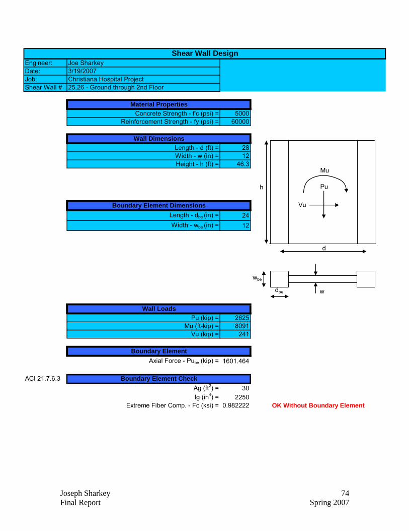
Joseph Sharkey 74 Final Report Spring 2007
Engineer: Joe SharkeyDate: 3/19/2007Job: Christiana Hospital ProjectShear Wall # 25,26 - Ground through 2nd Floor
Concrete Strength - f'c (psi) = 5000Reinforcement Strength - fy (psi) = 60000
Length - d (ft) = 28Width - w (in) = 12Height - h (ft) = 46.3
Length - dbe (in) = 24Width - wbe (in) = 12
Pu (kip) = 2625Mu (ft-kip) = 8091
Vu (kip) = 241
Axial Force - Pube (kip) = 1601.464
ACI 21.7.6.3Ag (ft2) = 30Ig (in4) = 2250
Extreme Fiber Comp. - Fc (ksi) = 0.982222
Wall Loads
Boundary Element
Boundary Element Check
OK Without Boundary Element
Shear Wall Design
Material Properties
Wall Dimensions
Boundary Element Dimensions
d
dbe
h
wbe
w
Pu
Vu
Mu

Joseph Sharkey 75 Final Report Spring 2007
ACI 21.7.2.2 One Curtain of Reinf. Req.Acv (in2/ft) = 144
Longitudinal - ρl, Transverse - ρt >= 0.0025Aslreq'd (in
2/ft) = 0.36Assupplied (in
2) = 0.62 #5 BarsBar Diameter (in) = 0.625
Required Spacing - Sreq'd (in) = 20.66667Spacing Supplied - Ssupplied (in) = 18
αc = hw/lw 1.543333Acvtotal (in
2) = 4320Transverse - ρt = 0.00287
Nominal Shear Capacity - Vn (kip) = 1215.442Shear Capacity - ФVn (kip) = 729.2653
Longitudinal & Transverse Reinforcement
NOT OK Spacing Must Be Less Than 18in
Shear Capacity Check
OK
Check With Interaction DiagramP (kip)
Mx (k-ft)
12000
-2000
50000-500 00
(Pmax)
(Pmin)
fs=0.5fy
fs=0
fs=0.5fy
fs=0
1