Embed Size (px)
Citation preview

September 2007 RG-348A
Optional Enhanced Measures for the Protection of Water Quality in the Edwards Aquifer (Revised)
Appendix A to RG-348— Complying with the Edwards Aquifer Rules: Technical Guidance on Best Management Practices
Prepared by the Chief Engineer ’s Off ice, Water Programs T E X A S C O M MI S S IO N O N E N V IR O N ME N T A L Q U A L IT Y

Optional Enhanced Measures for the Protection of Water Quality in the
Edwards Aquifer (Revised)
Appendix A to RG-348— Complying with the Edwards Aquifer Rules:
Technical Guidance on Best Management Practices
Prepared by Chief Engineer’s Office, Water Programs
RG-348A September 2007

Texas Commission on Environmental Quality H.S. Buddy Garcia, Chairman
Larry R. Soward, Commissioner
Glenn Shankle, Executive Director
Texas Commission on Environmental Quality P.O. Box 13087, MC-203 Austin, Texas 78711-3087
The TCEQ is an equal opportunity/affirmative action employer. The agency does not allow discrimination on the basis of race, color, religion, national origin, sex, disability, age, sexual orientation, or veteran status. In compliance with the Americans with Disabilities Act, this document may be requested in alternate formats by contacting the TCEQ at 512/239-0028, fax 239-4488, or 1-800-RELAY-TX (TDD), or by writing PO Box 13087, Austin, Texas 78711-3087. Authorization for use or reproduction of any original material contained in this publication, i.e., not obtained from other sources, is freely granted. The Commission would appreciate acknowledgment.

CONTENTS 1. Introduction .................................................................................................................. 12
2. Site Planning................................................................................................................. 32 2.1. Sensitive Features............................................................................................................. 32
2.2. Sensitive Features Identified During Construction ......................................................... 42
2.3. Caves ................................................................................................................................ 82
2.3.1. Gate Construction ............................................................................................... 102 2.4. Stream Buffers................................................................................................................ 112
3. Construction ............................................................................................................... 182
4. Permanent BMP Implementation ............................................................................... 192 4.1. Hazardous Material Traps (HMT).................................................................................. 192
4.2. Total Suspended Solids (TSS) Removal ........................................................................ 202
4.2.1. Step 1: Required TSS Removal .......................................................................... 202 4.2.2. Step 2: Select an Appropriate BMP .................................................................... 222 4.2.3. Step 3: Calculate TSS Load Removed by BMPs................................................ 222 4.2.4. Step 4: Calculate Fraction of Annual Runoff to Be Treated .............................. 232 4.2.5. Step 5: Calculate Capture Volume...................................................................... 232
5. Measures to Protect Stream Morphology................................................................... 252
6. Maintenance Requirements ........................................................................................ 282
7. References .................................................................................................................. 292
Figures Figure 2-1. Filled Solution Feature ............................................................................................62 Figure 2-2. Example of Filled Void in Trench Excavation ........................................................62 Figure 2-3. Utility Pipe Encased in External Steel Pipe.............................................................72 Figure 2-4. Profile View of Encased Utility Pipe.......................................................................72 Figure 2-5. Cavity Fill with Pipe to Preserve Hydrologic Connectivity ....................................82 Figure 2-6. Typical Cave Gate with Secure Entrance ................................................................92 Figure 2-7. Mammal Access Portals along Edge of Gate ........................................................102 Figure 2-8. Example of Anchor Rebar .....................................................................................112 Figure 2-9. Example Cave Gate Access ...................................................................................122 Figure 2-10. Traditional Development Adjacent to Stream Buffer............................................142 Figure 2-11. Example of Small Lot Cluster Type Development................................................152 Figure 2-12. Example of Large Lot Low Density Development................................................162 Figure 2-13. Detail of Road Section Showing Vegetated Treatment Areas...............................172 Figure 2-14. Detail of Lot Layout with Water Quality Easements ............................................172 Figure 4-1. Hazardous Material Trap inside Sand Filter ..........................................................192 Figure 4-2. Typical TxDOT Automatic Siphon Detail ............................................................202 Figure 4-3. Relationship between Runoff Coefficient and Impervious Cover.........................242
Appendix A
TCEQ publication RG-348A # Revised # September 2007 iii

Tables Table 2-1. Minimum Protective Standards for Sewer and Storm Drain Trenches....................52 Table 3-1. Capture Volumes for Sediment Basins..................................................................182 Table 4-1. Impervious Cover Assumptions for Residential Tracts.........................................212 Table 4-2. Average Annual Rainfall by County .....................................................................212 Table 4-3. Approved BMPs and TSS Removal Efficiency.....................................................222 Table 4-4. Relationship between Fraction of Annual Rainfall and Rainfall Depth ................242 Table 5-1. Average Annual Rainfall by County .....................................................................262
Appendix A
TCEQ publication RG-348A # Revised # September 2007 iv

1. Introduction One of the goals of the Texas Commission on Environmental Quality (TCEQ) Edwards Aquifer Rules is "the existing quality of groundwater not be degraded, consistent with the protection of public health and welfare, propagation and protection of terrestrial and aquatic life, the protection of the environment, the operation of existing industries, and the maintenance and enhancement of long-term economic health of the state" (Title 30 Texas Administrative Code §213.1(1)). This document presents optional water quality protection measures that may be implemented in areas subject to the TCEQ Edwards Aquifer Rules (30 TAC Chapter 213).
The optional water quality measures and best management practices (BMPs) contained in this document have been reviewed by the United States Fish and Wildlife Service (USFWS), which has issued a concurrence that these voluntary enhanced water quality measures will protect en-dangered and candidate species from impacts due to water quality degradation. USFWS approved the predecessor document to this revised appendix on February 14, 2005. This revised and up-dated appendix was approved by correspondence from Dr. Benjamin N. Tuggle, USFWS Regional 2 Director to Governor Rick Perry dated September 4, 2007. This letter identified the following species as being included under this "no take" concurrence:
� Barton Springs salamander (Eurycea sosorum), � fountain darter (Etheostoma fonticola), � Georgetown salamander (Eurycea naufragia), � San Marcos salamander (Eurycean nana), and � San Marcos gambusia (Gambusia georgei).
This concurrence is not a delegation of the USFWS’s responsibilities under the Endangered Spe-cies Act (ESA), but rather an acknowledgement that the TCEQ Edwards Aquifer Protection Program with these enhanced water quality measures addresses known threats to the identified species.
If these practices contained in this document are used, they are expected to result in "no take" of these species from degradation of water quality by non-Federal landowners and other non-Federal managers.1 This "no take" concurrence does not cover projects that: (1) occur outside the area regulated under the Edwards Aquifer Rules; (2) result in water quality impacts that may affect Federally-listed species not specifically named above; (3) result in impacts to Federally-listed species that are not water quality related; or (4) occur within one mile of spring openings that provide habitat for Federally-listed species.
It is the responsibility of the applicant to determine the potential for impacting endangered spe-cies and take appropriate action based upon this information. The USFWS maintains a county-by-county list of endangered species on its web site at <www.fws.gov/southwest/es/Endangered Species/lists/>. This list is subject to change as new biological information is gathered and should NOT be used as the sole and final source for identifying species that may be impacted by a pro-ject. Please contact the appropriate USFWS field office(s) to get additional information.
1 Section 9 of the Endangered Species Act (Act) and Federal regulations adopted under section 4(d) of the Act prohibit the "take" of endangered and threatened species without special exemption. Take of listed species is defined as harass, harm, pursue, hunt, shoot, wound, kill, trap, capture or collect, or to attempt to engage in such conduct. Harass is fur-ther defined as an intentional or negligent act or omission that creates the likelihood of injury to a listed species by annoying it to such an extent as to significantly disrupt normal behavioral patterns. Harm includes significant habitat modification or degradation that results in death or injury to listed species.
Appendix A
TCEQ publication RG-348A # Revised # September 2007 1

These optional measures are designed to enhance the protection of the species covered under this document by providing for a higher level of water quality protection and can be used by those who wish to avoid harming listed species from water quality impacts. It is the responsibility of the applicant to determine whether the optional water quality measures and best management practices described in this document are appropriate for their project.
While these measures are not mandatory under the Edwards Aquifer Protection Program, they may be submitted to the TCEQ for review as part of an Edwards Aquifer Protection Plan or a Contributing Zone Plan. An applicant who chooses to implement the measures and best manage-ment practices contained in this document will still have to comply with all other applicable requirements for the development of land under the Edwards Aquifer Protection Program and rules.
The TCEQ cannot grant variances to the measures and best management practices contained in this document. If the applicant wishes to implement these water quality measures to fulfill the "no take" concurrence by USFWS, variances from the water quality measures and best management practices under the TCEQ Edwards Aquifer Protection Program will not be allowed as part of the approved plan. If the applicant wishes a variance, the TCEQ cannot issue a plan approval letter which indicates the plan is in compliance with the measures contained in this document. If the water quality measures required to be in compliance with this document cannot be implemented fully, the applicant may initiate direct consultation with USFWS to determine if their develop-ment will result in "no take" thereby ensuring that the requirements of the Endangered Species Act have been met.
The optional water quality measures contained in this document may be implemented by appli-cants conducting regulated activities in the areas subject to the TCEQ Edwards Aquifer Protection Program as delineated in the rules found in Title 30 Texas Administrative Code Chap-ter 213 Edwards Aquifer at <www.tceq.state.tx.us/rules/index.html> and on maps available at <www.tceq.state.tx.us/compliance/field_ops/eapp/program.html>.
Activities within the Contributing Zone that disturb less than five acres, or are not part of a larger common plan of development or sale with the potential to disturb cumulatively five or more acres, are not subject to regulation under Subchapter B of the Edwards Aquifer Rules. Therefore, these activities are not eligible to be reviewed by the TCEQ.
The following sections describe the process and requirements for implementing the optional en-hanced measures and best management practices. Section 2 describes the site planning process and the need for a Geological Assessment early in the project development phase. BMPs are de-scribed for sensitive features identified during the assessment or after construction has begun. Section 3 presents the sizing requirements for sediment basins used to manage construction run-off and Section 4 covers hazardous material traps and the calculations used to size storm water treatment systems for post construction runoff management. Section 5 describes the requirements for managing runoff volume to help preserve stream morphology and prevent channel erosion. Finally, Section 6 presents the additional maintenance requirements to comply with these optional measures.
Appendix A
TCEQ publication RG-348A # Revised # September 2007 2
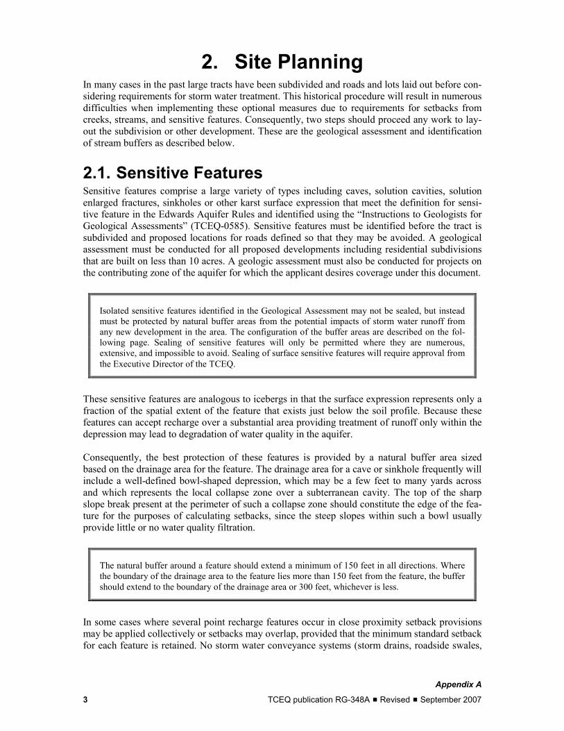
2. Site Planning In many cases in the past large tracts have been subdivided and roads and lots laid out before con-sidering requirements for storm water treatment. This historical procedure will result in numerous difficulties when implementing these optional measures due to requirements for setbacks from creeks, streams, and sensitive features. Consequently, two steps should proceed any work to lay-out the subdivision or other development. These are the geological assessment and identification of stream buffers as described below.
2.1. Sensitive Features Sensitive features comprise a large variety of types including caves, solution cavities, solution enlarged fractures, sinkholes or other karst surface expression that meet the definition for sensi-tive feature in the Edwards Aquifer Rules and identified using the “Instructions to Geologists for Geological Assessments” (TCEQ-0585). Sensitive features must be identified before the tract is subdivided and proposed locations for roads defined so that they may be avoided. A geological assessment must be conducted for all proposed developments including residential subdivisions that are built on less than 10 acres. A geologic assessment must also be conducted for projects on the contributing zone of the aquifer for which the applicant desires coverage under this document.
Isolated sensitive features identified in the Geological Assessment may not be sealed, but instead must be protected by natural buffer areas from the potential impacts of storm water runoff from any new development in the area. The configuration of the buffer areas are described on the fol-lowing page. Sealing of sensitive features will only be permitted where they are numerous, extensive, and impossible to avoid. Sealing of surface sensitive features will require approval from the Executive Director of the TCEQ.
These sensitive features are analogous to icebergs in that the surface expression represents only a fraction of the spatial extent of the feature that exists just below the soil profile. Because these features can accept recharge over a substantial area providing treatment of runoff only within the depression may lead to degradation of water quality in the aquifer.
Consequently, the best protection of these features is provided by a natural buffer area sized based on the drainage area for the feature. The drainage area for a cave or sinkhole frequently will include a well-defined bowl-shaped depression, which may be a few feet to many yards across and which represents the local collapse zone over a subterranean cavity. The top of the sharp slope break present at the perimeter of such a collapse zone should constitute the edge of the fea-ture for the purposes of calculating setbacks, since the steep slopes within such a bowl usually provide little or no water quality filtration.
The natural buffer around a feature should extend a minimum of 150 feet in all directions. Where the boundary of the drainage area to the feature lies more than 150 feet from the feature, the buffer should extend to the boundary of the drainage area or 300 feet, whichever is less.
In some cases where several point recharge features occur in close proximity setback provisions may be applied collectively or setbacks may overlap, provided that the minimum standard setback for each feature is retained. No storm water conveyance systems (storm drains, roadside swales,
Appendix A
TCEQ publication RG-348A # Revised # September 2007 3

etc.) that would bring runoff from outside the existing drainage area should have outfalls where the runoff would be directed to a sensitive feature by the natural topography.
The "natural state" of a buffer will typically be a combination of dense native grasses and forbs in a mosaic of shrubs and trees. Native vegetation, particularly live oak trees, should be preserved within the catchment area of caves or sinkholes. Stream flow occurring along the branches and trunks of large trees may enhance infiltration by channeling rainfall to the root zone (Thurow et al., 1987). Introduction of ornamental turf or landscaping within the catchment area is not rec-ommended because it will probably require soil amendments, frequent maintenance, and application of fertilizers, pesticides, and herbicides. The existing soil structure and vegetation are compatible with pre-existing recharge conditions and should require little maintenance.
It is recommended that the buffers around a point recharge feature or cluster of contiguous point recharge features be maintained in a natural state to the maximum practical extent. This implies a construction-free zone. Activities and structures allowed within buffer zones are limited. Residen-tial yards and hiking trails may be located in buffer zones as long as they are at least 50 feet from the feature. The allowance of "yards" within a buffer zone should not be taken to imply that regu-lar landscaping is appropriate for buffers. In addition, pesticides and fertilizers should not be applied within the buffer area.
Temporary runoff protection measures should be installed according to the recommendations pre-sented in RG-348 during any construction activities within drainage area of the feature. Temporary erosion control measures should be placed as near the construction as possible to minimize disturbance within the buffer zones and drainage areas.
Where extenuating circumstances exist and development over a significant point recharge feature and its catchment is proposed, the developer can consider demonstrating that no feasible alter-natives to construction over the sensitive feature exist. Feasibility of alternatives should be based primarily on technical, engineering, and environmental criteria. Feasibility should not be based predominantly on marketing or economic considerations or special or unique conditions which are created as a result of the method by which a person voluntarily subdivides or develops land. An example of a situation where sealing a sensitive feature might be warranted is when the number and distribution of features is such that access is precluded to a substantial portion of the tract that might otherwise be developable.
2.2. Sensitive Features Identified During Construction
Many sensitive features, such as solution cavities and caves, are not identified during the Geo-logical Assessment, but are discovered by excavation during the construction phase of a project. This is especially common during utility trenching. The features encountered at this phase of a project must be protected to ensure that water quality and the stability of the utility installation are protected. Rerouting of the utility is always an option and realignment of the line should be con-sidered.
Features discovered during construction of roads, houses, or other facilities, which do not involve below grade utility installation, shall be filled with concrete. Gravel to “fist sized” rock or sacks of gravel may be placed in feature prior to placement of the concrete as long as a minimum of eighteen (18) inches of concrete is used to close the feature.
Table 2-1 describes the various types of features and the minimum treatment required when con-structing sewers, storm drains or other underground utilities. There are two main strategies for
Appendix A
TCEQ publication RG-348A # Revised # September 2007 4

dealing with these features depending on their extent. Small, isolated solution cavities may be completely filled with concrete. An example of the proper method of dealing with this type of feature is shown in Figure 2-1. The feature is completely filled with concrete and typical bedding and backfill material is used in the trench.
Table 2-1. Minimum Protective Standards for Sewer and Storm Drain Trenches
(from Table 5-1 Edwards Aquifer Guidance Document RG-348, Revised July 2005)
Case Description Concern Treatment Notification/ Approval
1 Sensitive feature is less than or equal to six (6) inches in all di-rections and is located above the embedment of the pipe. All rock within and surrounding the fea-ture is sound.
Not environ-mental nor pipe integrity
No abatement required. None required.
2 Sensitive feature is either larger than six (6) inches in at least one direction or is located within the level of the pipe embedment. No portion of the sensitive feature may intersect the plane of trench floor. All rock within and sur-rounding the feature is sound.
Environmental The sensitive feature shall be filled with concrete. Gravel to “fist sized” rock or sacks of gravel may be placed in feature prior to placement of the con-crete as long as a minimum of eighteen (18) inches of concrete is used to close the feature).
Requires notifi-cation and prior written ap-proval from the TCEQ.
3 Sensitive feature intersects the plane of the trench floor is less than four (4) feet in any direction. All rock within and surrounding the feature is sound.
Environmental Sensitive feature shall be filled with concrete. Gravel to “fist sized” rock or sacks of gravel may be placed in feature prior to placement of concrete at least eighteen (18) inches of concrete is used to close the feature. The sewer line or storm sewer lines shall be concrete encased for width of the sensitive feature plus a minimum of five (5) feet on either end. The encasement shall provide a minimum of six (6) inches of concrete on all sides of the pipe and shall have compression strength of at least 2,500 psi (28-day strength). The concrete may be steel reinforced.
Requires notifi-cation and prior written ap-proval from the TCEQ.
4 Sensitive feature intersects the plane of the trench floor and any opening in trench floor is greater than four (4) feet in any direction or the trench floor is unstable.
Environmental & Structural
Requires an engineered resolu-tion at least as protective as Case 3 above. Additional protective measures, including rerouting of line, may be required.
Requires notifi-cation and prior written ap-proval from the TCEQ.
All plans submitted to the TCEQ regional office shall have a signed and dated seal of a Texas licensed Professional Engineer. All plans will be reviewed on a case-by-case basis and additional protective measures or additional information may be required.
Other features discovered during trenching operations are much more extensive and filling of the feature is neither possible nor desirable. In cases where there does not appear to be substantial, active flow in the feature, it may be possible to isolate the section in the vicinity of the trench from the rest of the cave system. An example of this type of installation is shown in Figure 2-2. Sand bags are installed to restrict fill to the vicinity of the trench and concrete is used to fill the lower part of the trench and support the pipe.
Appendix A
TCEQ publication RG-348A # Revised # September 2007 5

Figure 2-1. Filled Solution Feature (courtesy Kathryn Woodlee)
Figure 2-2. Example of Filled Void in Trench Excavation (courtesy Donald Bayes)
In some cases, it might not be desirable to permanently encase the utility pipe in concrete, espe-cially where the pipe may need to be removed for repair or replacement. In those circumstances an outer steel encasement pipe can be installed and the utility pipe installed inside of it. Section and profile views of this type of installation are shown in Figure 2-3 and Figure 2-4.
Appendix A
TCEQ publication RG-348A # Revised # September 2007 6

Figure 2-3. Utility Pipe Encased in External Steel Pipe (courtesy of Kathryn Woodlee)
Figure 2-4. Profile View of Encased Utility Pipe (courtesy of Kathryn Woodlee)
When a larger feature appears be an active conduit for flow, it may be appropriate to maintain hydrologic connectivity across the trench excavation. This can be accomplished by installing a 3-inch Schedule 40 PVC pipe between the two isolated cave sections. An example of this type of installation is shown in Figure 2-5.
Appendix A
TCEQ publication RG-348A # Revised # September 2007 7

Figure 2-5. Cavity Fill with Pipe to Preserve Hydrologic Connectivity
Temporary covering of voids when construction activities are halted can be accomplished by covering with filter fabric and then plywood weighted with concrete blocks. This will prevent sediment from the trench being inadvertently introduced into the cavity.
2.3. Caves Openings of caves are sensitive features that should have natural buffers as described above. In addition, the size of the opening creates the opportunities for other pollutants to enter the aquifer. Many caves in the Edwards were historically used for trash, debris, and garbage disposal. The material found in caves often includes paint, solvents, and other toxic/hazardous materials. Run-off entering the caves can leach toxic compounds and convey them to the aquifer. Consequently, caves that are identified in the geological assessment and that have openings large enough to ac-commodate a person must be fitted with a cave gate such as the one shown in Figure 2-6.
The gate has two main purposes. The first is to reduce access to the cave and prevent the disposal of wastes in these sensitive features. The second purpose is to prevent untrained individuals from accessing the cave where they might potentially become trapped. The gate should also provide a lockable access for qualified individuals to perform hydrogeological or biological studies. The discussion of cave gates below is modified from Warton (2002).
Appendix A
TCEQ publication RG-348A # Revised # September 2007 8

Many of these caves are habitat for endangered species; consequently, the gate should provide for free exchange of air, water, organic debris, and small mammals that are important components of the cave ecosystem. If caves or other sensitive features contain Federally-listed endangered spe-cies, such as karst invertebrates, project planners should contact the USFWS to ensure that their activities will not “take” a listed species. The applicant may also wish to consult the TCEQ’s Op-tional Enhanced Measures for the Protection of Water Quality in the Edwards Aquifer and Related Karst Features that may be Habitat for Karst Dwelling Invertebrates: Appendix B to RG-348.
Figure 2-6. Typical Cave Gate with Secure Entrance (Mike Warton, PBS&J)
In Central Texas, the most common type of cave entrance occurs as a sinkhole, often found along rock joints. Entrance openings are usually positioned on semi-flat ground or along hillside slopes. The orientation of entrance openings is usually vertical. Horizontal development within caves may occur at shallow depths. In this type of cave structure, the key position of a prospective cave gate is usually horizontal, with some degree of recess in to the entrance.
Appendix A
TCEQ publication RG-348A # Revised # September 2007 9

The concept of gate "transparency" implies specifically that the gate is a non-solid covering that will not impede, block, or prevent the vertical fall of air, water, or natural organic materials from entering the cave similar to what occurs naturally. Thus, the transparent gate is semi-open for these functions. In the cave entrance ecosystem, surface related and nocturnal invertebrate species may regularly pass through the gate in a manner not significantly altered by the presence of the gate. In Texas, endangered invertebrate species are troglobitic in nature, never leave the cave en-vironment, and never use or access the gate. They are critically dependent on the gate’s ability to allow un-impeded wash-in, or transport of organic food source materials to enter and replenish the cave. Up to seven common types of ground mammals also frequent Texas caves and have im-portant natural roles in the cave ecosystem. Their points of access and egress through the cave gate are specific in location. The gate must facilitate their easiest points of access. The access por-tal design and size are set to an eight-inch diameter or square opening as shown in Figure 2-7.
Figure 2-7. Mammal Access Portals along Edge of Gate
2.3.1. Gate Construction Prior to gate construction, the cave’s entrance may require certain preparations for acceptance of the gate. In welded construction where gates are custom built and fitted on site, commercially made welding blanket mats should be draped across the entrance opening in basket position in order to prevent contamination of the cave by slag and welding residues. The gate is a level hori-zontal grid cover constructed from 2-inch by 2-inch by 3/8-inch steel angle. The most important structural component is the supporting sub-structured arrangement of cross beams and drilled an-chor points. Anchors are usually 1/4-inch to 1-inch diameter rebar from 8-inches to 10-inches in length (Figure 2-8).
Horizontal beam supports are built by welding together two pieces of angle iron to form a box-shaped beam that is solid welded to the point set anchors. Once the substructure is completed, the grid panel arrangement of bar angles may begin. The bar angles are placed on their edge sides,
Appendix A
TCEQ publication RG-348A # Revised # September 2007 10

with angle peak pointed either to the left or to the right (all pointed in the same direction through-out the gate). By placing the angles on their edge side, the barrier thickness aspect of the gate panel becomes almost three inches thick, instead of the 3/8-inch thickness of the angle. Bar spac-ing throughout the gate and across the panel are set to provide a clear opening of 1.5 inches if the cave is not used by bats, otherwise the opening should be 5.75 inches. The direction of airflow exchange to and from the cave’s entrance may determine the left or right pointing positions of angle peaks. The angle shape would be turned to such a position that "cups" and promotes the best airflow exchange. It should provide the level of airflow conductivity that is a substantial or prominent characteristic of the cave. In this construction, the location and position of the gate’s access and egress door is pre-determined. The access door assembly is: (1) typically 30 inches square; (2) transparent in design; (3) a hinged door; and (4) contains a concealed lock mechanism and access point as shown in Figure 2-9. The round hole in the gate is sized so that a person can reach through the gate to access the lock with is concealed below the gate. The concealed lock box location in these gates prevents any direct attack. The lock box is designed to house a 2-inch wide lock with 3/8-inch shackle.
After the access door is installed, the last stage of the construction is usually the placement of horizontal stiffeners across angle expanses. One-inch or 2-inch wide by 3/8-inch thick flat bar stock is used for the stiffeners. Stiffener spacing usually does not exceed a distance of five feet. Following the completion of all welding, the last stage of gate completion is to apply a protective metal coating with a high quality rust inhibitive paint. This is carefully hand brushed on instead of sprayed. Following gate completion, the under hanging blanket basket is removed and the site should be thoroughly cleaned of any foreign materials.
Figure 2-8. Example of Anchor Rebar
2.4. Stream Buffers Natural buffer areas adjacent to streams and natural drainage ways play an important role in maintaining predevelopment water quality. The riparian vegetation stabilizes stream channels and
Appendix A
TCEQ publication RG-348A # Revised # September 2007 11

Figure 2-9. Example Cave Gate Access
floodplain areas, reducing erosion. In addition, they provide an area to filter overland flow from adjacent development. Consequently, all streams should have an undisturbed native vegetation buffer on each side as follows:
� Streams draining 640 acres (one square mile) or greater should have a minimum buffer of 300 feet from the centerline on each side of the stream.
� Streams draining less than 640 acres but 320 or more acres should have a mini-mum buffer of 200 feet from the centerline on each side of the stream.
� Streams draining less than 320 acres but 128 or more acres should have a minimum buffer of 100 feet from the centerline on each side of the stream.
� Streams or swales draining less than 128 acres but 40 or more acres should have a minimum buffer of 50 feet from the centerline on each side of the drainage.
� Streams or swales draining less than 40 acres but 5 or more acres should have a mini-mum buffer of 25 feet from the centerline on each side of the drainage.
Site plans submitted for TCEQ review must show the location of all stream buffers in addition to the plan elements required by the Edwards Aquifer Rules. If the area within the designated buffer has been altered by clearing, construction, or other activities, then USFWS must be consulted.
Buffer zones should generally remain free of construction, development, or other alterations, al-though storm water treatment systems can be constructed there if the natural drainage to the site is less than 128 acres. The number of roadways crossing through the buffer zones should be mini-mized and constructed only when necessary, such as when a significant portion of the site can only be reached by crossing a buffer zone. An example of a situation when a road crossing was necessary is shown in Figure 2-11. Note that there is only a single crossing of each buffer.
Appendix A
TCEQ publication RG-348A # Revised # September 2007 12

Other alterations within buffer zones could include utility crossings, but only when necessary, fences, low impact parks, and open space. Roadways and utilities crossings should be approxi-mately perpendicular to the buffer zone. Low impact park development within the buffer zone should be limited to trails, picnic facilities, and similar construction that do not significantly alter the existing vegetation. Parking lots and roads significantly alter existing vegetation and are not considered low impact. Neither golf course development nor wastewater effluent irrigation shall take place in the buffer zone.
These restrictions are an important reason why buffer zones must be identified before the tract is subdivided. Various types of development are consistent with stream buffers as demonstrated be-low. One type is a typical suburban single-family development with a lot density, three to four lots per acre that necessitates the use of curb and gutter. In this scenario essentially all the imper-vious cover is connected. Storm water runoff drains directly to the street where it is captured in an inlet and conveyed by storm sewer in a system that requires larger pipe diameters as more and more area contributes. Discharge is then directed to a creek at the lower end of the development or to a constructed trapezoidal channel.
The conventional design philosophy has been to convey the storm water runoff quickly and safely away from the subdivision. Depending upon local requirements, a water quality pond may be constructed just prior to discharge to the creek. Even if a pond is provided, little or no utilization of buffers occurs. Figure 2-10 provides an example of a 144-lot single-family subdivision bound on one side by a creek with 150 feet of buffer width on each side. In this case a sedimentation-filtration pond is provided at the downstream end. For this example, approximately 39 acres of development are conveyed to the pond, totally bypassing the buffer.
Figure 2-11 is an example of small, clustered single-family lots situated around stream buffers. This clustering leaves large undisturbed areas of land as well as setbacks from the creeks. These small lots, 60 – 80 feet of frontage, require storm sewers, but with the creek setbacks, sufficient area is available for frequent storm sewer discharges up-gradient from the creek buffer. While it is difficult to completely offset the hydrologic impact of a development of this density, the set-backs and maximizing of sheet flow minimizes the impacts. In-stream ponds are provided in this example to supplement the vegetative measures for water quality and provide peak flow control.
Figure 2-12 is an example of a larger, rural lot subdivision (individual lots larger than one acre) with buffers meeting the criteria described in this document. These size lots offer an opportunity to maximize sheet flow and reduce the area contributing to a concentrated discharge that must then be returned to sheet flow by the methods discussed previously. Traditionally, the roadways would have a roadside ditch on both sides. However, in a design maximizing sheet flow, the half of the roadway draining to the low side of the right-of-way is allowed to continue as sheet flow into the large single-family lot (Figure 2-13). Also note that the limit of disturbance is only a frac-tion of the lot size (Figure 2-14).
Greater building setbacks allow the builder to easily route any drainage around the house. Drain-age or conservation easements must be shown on approved plats and deed restrictions provided to the home buyer limit landscaping to native or native adapted plants that require little or no fertil-izers and are disease resistant. With these simple design features, the effective buffer width along streams is increased and unconnected impervious cover is maximized. On the uphill side of the roadway, the roadside swale has multiple points of discharge under the roadway, much as a storm sewer in a more dense development. This drainage is then conveyed in an easement along lot lines and then returned to sheet flow at the buffer.
Appendix A
TCEQ publication RG-348A # Revised # September 2007 13

STREAM BUFFER
14
WATER QUALITY POND
STORM SEWER
INLET
39 ACRE DRAINAGE AREA
Figure 2-10. Traditional Development Adjacent to Stream Buffer (courtesy Murfee Engineering)

15
Figure 2-11. Example of Small Lot Cluster Type Development (courtesy Murfee Engineering)

16
Figure 2-12. Example of Large Lot Low Density Development (courtesy Murfee Engineering)
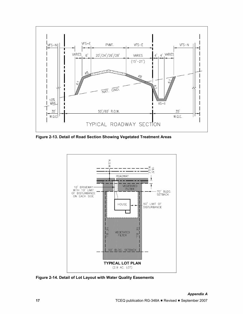
Figure 2-13. Detail of Road Section Showing Vegetated Treatment Areas
Figure 2-14. Detail of Lot Layout with Water Quality Easements
Appendix A
TCEQ publication RG-348A # Revised # September 2007 17

3. Construction Erosion and control measures for construction activities are described in RG-348. These measures also apply to construction activities conducted in compliance with these enhanced protection measures with the following additional requirements.
1) Sediment basins and traps, which are required for common drainage areas serving at least 10 acres, will be designed to capture the runoff from the 2-yr, 24-hour storm. These volumes area shown in Table 3-1.
Table 3-1. Capture Volumes for Sediment Basins County Cubic Feet/Acre Bexar 8,000 Comal 8,000 Hays 8,000 Kinney 7,250 Medina 8,000 Travis 8,000 Uvalde 8,000 Williamson 8,000
2) Temporary sediment basins and traps must not be installed in the buffer areas of natural drainages with a tributary area of more than 128 acres.
Appendix A
TCEQ publication RG-348A # Revised # September 2007 18

4. Permanent BMP Implementation This section describes the configuration and sizing of permanent best management practices (BMPs) to meet the requirements of these optional measures. Additional information regarding design criteria and maintenance of BMPs is contained in RG-348.
4.1. Hazardous Material Traps (HMT) Roadways capable of conveying at least 25,000 vehicles a day must include a hazardous material trap (HMT). These HMTs must be designed to retain a spill of 10,000 gallons of liquid hazardous material. These may be of a variety of designs including those used previously by the Texas De-partment of Transportation (TxDOT). Figure 4-1 demonstrates how an HMT can be sited within the footprint of the storm water control (a sand filter in this case) to achieve both objectives with-out increasing the land or hydraulic head required. Note that the invert of the openings from the splitter box to the HMT is set slightly lower than those into the sedimentation basin. This allows any hazardous spills as well as the first flush of runoff to be captured by the HMT. Once the HMT is full the backwater level rises and allows the remaining runoff to enter the sedimentation basin directly.
Figure 4-1. Hazardous Material Trap inside Sand Filter
To eliminate the need for manual draining of a hazardous material trap after a rain event, TxDOT developed an automatic siphon system to drain the HMT when it fills with rainwater. Figure 4-2 shows a typical siphon detail from a set of TxDOT construction plans.
Appendix A
TCEQ publication RG-348A # Revised # September 2007 19

2 ft 7 ft Frame and Lid
1.5’ Hole for Valve Access 1.0’ 1.5’ 1.5’ 1.5’
Hazardous Material Volume
Dome Drain
4” PVC Drain
12” Clay Liner 4” Sch. 40 Galv. Valve Closed Steel Pipe Valve Open
4” Eccentric Plug Valve
Figure 4-2. Typical TxDOT Automatic Siphon Detail
The siphon device is designed to drain the trap after it becomes full from a rain event, but is in-stalled at an elevation above the full capacity of the trap. Therefore, as long as a hazardous material spill does not occur during a rain event the system should contain the spill. The siphon is provided with bypass and shutoff valves so that alert on-scene responders can shutoff the auto-matic siphon and thereby maintain some containment even in the event of a concurrent rain/spill. Other options for spill containment are presented in the main section of RG-348.
4.2. Total Suspended Solids (TSS) Removal
4.2.1. Step 1: Required TSS Removal
Reduction of 80% of the annual TSS load in storm water runoff from a site is required for all new development, without regard to the proposed level of impervious cover. On redevelopment pro-jects that involve major changes to existing impervious cover and include modification of the drainage system, 80% TSS removal must be achieved for the entire project.
Examples of redevelopment projects where the entire site must be treated include highway widen-ing projects, a change in land use from single family residential to multifamily or commercial, and substantial expansion of impervious cover on an existing commercial development.
All the TSS load calculations are based on Equation 4.1
Equation 4.1 L = A × P × Rv × C × 0.226
Where: L = annual pollutant load (pounds) A = Contributing drainage area (acres) P = Average annual precipitation (inches) Rv = Appropriate runoff coefficient C = Average TSS concentration (mg/L) 0.226 = units conversion factor
Appendix A
TCEQ publication RG-348A # Revised # September 2007 20

Monitoring data from the City of Austin indicates that the TSS concentration from developed ar-eas is 170 mg/L and that from natural areas is 80 mg/L. Consequently, the required 80% load reduction is calculated as:
Equation 4.2 LM = (0.8× 0.226)(A× P × 0.9 ×170)
Where: LM = Required TSS removal (pounds) A = Impervious area (acres) P = Average annual precipitation (inches)
This equation simplifies to:
Equation 4.3 L = 27.7(A× P)
Where: L = Required TSS removal (pounds) A = Impervious area (acres) P = Average annual precipitation (inches)
Imperviousness is the percent, or decimal fraction, of the total site area covered by the sum of roads, parking lots, sidewalks, rooftops and other impermeable surfaces. Roof areas directed to rainwater harvesting systems are exempt from the treatment requirement. When calculating the impervious area of a residential development the assumptions shown in Table 4-1 will apply to impervious area on each lot to the lot size, unless the actual future impervious cover is known to be greater. Annual precipitation by county is shown in Table 4-2.
Table 4-1. Impervious Cover Assumptions for Residential Tracts
Lot Size Assumed Impervious Cover (ft2)
> 3 acres 10,000
Between 1 and 3 acres 7,000
Between 15,000 ft2 and 1 acre 5,000
Between 10,000 and 15,000 ft2 3,500
<10,000 ft2 2,500
Table 4-2. Average Annual Rainfall by County
County Average Annual Precipitation (inches) Bexar 30 Comal 33 Hays 33 Kinney 22 Medina 28 Travis 32 Uvalde 25 Williamson 32
Appendix A
21 TCEQ publication RG-348A # Revised # September 2007

4.2.2. Step 2: Select an Appropriate BMP Select a BMP or series of BMPs that will achieve at least an 80% reduction in TSS. The higher the efficiency of the BMP, the less runoff that will need to be treated to achieve the required re-duction. The TSS removal efficiency for each approved BMP is shown in Table 4-3.
Table 4-3. Approved BMPs and TSS Removal Efficiency
BMP TSS Reduction (%)
Retention/Irrigation 100 AquaLogic™ Cartridge Filter System 95
Wet Basins 93
Constructed Wetlands 93
Sand Filters 89
Bioretention 89
Vegetated Filter Strips 85
Ext. Detention Basin 75
Grassy Swales 70
Wet Vault See Section 3.3 of RG-348, Revised July 2005
4.2.3. Step 3: Calculate TSS Load Removed by BMPs The following section describes how to determine the load removed by a proposed BMP(s). The load removed depends on the amount of TSS entering the BMP(s) and its effectiveness.
The load entering each BMP is calculated from the sum of the contribution of the impervious and pervious areas with their respective storm water concentrations for the BMP catchment area. This calculation assumes that no runoff bypasses the treatment facility and assigns the appropriate runoff coefficient and TSS concentrations to the pervious and impervious areas.
Equation 4.4 LR = (BMP efficiency) x 0.226 x P x (AI x 0.9 x 170 mg/L + AP x 0.03 x 80 mg/L)
Where: LR = Load removed by BMP BMP = TSS removal efficiency (expressed as a decimal fraction from ) AI = impervious tributary area to the BMP (ac) AP = pervious tributary area (ac) P = average annual precipitation (inches, Table 4-2)
Which simplifies to:
Equation 4.5 LR = (BMP efficiency) x P x (AI x 34.6 + AP x 0.54)
Appendix A
TCEQ publication RG-348A # Revised # September 2007 22

4.2.4. Step 4: Calculate Fraction of Annual Runoff to Be Treated
Based on the load reduction calculated above for each of the BMPs installed at the site and the required load reduction, calculate the fraction of annual runoff to be treated using Equation 4.6. This calculation assumes a constant concentration of TSS in the runoff.
LEquation 4.6 F =
∑LR
Where: F = Fraction of the annual rainfall treated by the BMP LR = Load removed for each BMP from Step 3 calculation (pounds) L = Required load reduction from Step 1 (pounds)
4.2.5. Step 5: Calculate Capture Volume This step relates the statistical properties of storm size and flow rate in the regulated area to the total volume of runoff. These calculations depend on whether the BMP is a capture and treat de-vice, such as a sand filter system, or a flow through BMP such as a swale or wet vault.
For flow through type devices (swales and wet vaults), the size is calculated using a rainfall in-tensity of 1.1 inches/hour. Capture volume for capture-and-treat devices is developed from Table 4.4, which relates rainfall depth to the percentage of annual rainfall that occurs in storms less than or equal to this depth—i.e., 100% of the annual rainfall occurs in storms of 4 inches or less on average, while 78% of the annual runoff occurs in storms of an inch or less. For BMPs designed to capture and treat the runoff, the value, F, calculated in Step 4 is used to enter Table 4-4and find the rainfall depth associated with this fraction.
Once the appropriate rainfall depth has been determined from Table 4-4, the water quality volume for each BMP can be calculated from:
Equation 4.7 WQV = Rainfall depth x Runoff Coefficient x Area
Where the rainfall depth is determined from Table 4-4, the runoff coefficient comes from Figure 4-3 or is calculated using Equation 4.8, and the area is the portion of site contributing runoff to the BMP.
Equation 4.8 Rv = 0.05 + 0.0085(IC)
Where: IC = Percent impervious cover
Appendix A
TCEQ publication RG-348A # Revised # September 2007 23

Table 4-4. Relationship between Fraction of Annual Rainfall and Rainfall Depth (inches)
Rainfall Rainfall Rainfall Rainfall F Depth F Depth F Depth F Depth
1.00 4.00 0.80 1.08 0.60 0.58 0.40 0.29
0.99 3.66 0.79 1.04 0.59 0.56 0.39 0.28
0.98 3.33 0.78 1.00 0.58 0.54 0.38 0.27
0.97 3.00 0.77 0.97 0.57 0.52 0.37 0.25
0.96 2.80 0.76 0.94 0.56 0.50 0.36 0.24
0.95 2.60 0.75 0.92 0.55 0.49 0.35 0.23
0.94 2.40 0.74 0.89 0.54 0.47 0.34 0.23
0.93 2.20 0.73 0.86 0.53 0.46 0.33 0.22
0.92 2.00 0.72 0.83 0.52 0.45 0.32 0.21
0.91 1.91 0.71 0.80 0.51 0.44 0.31 0.20
0.90 1.82 0.70 0.78 0.50 0.42 0.30 0.19
0.89 1.73 0.69 0.75 0.49 0.41 0.29 0.18
0.88 1.64 0.68 0.73 0.48 0.40 0.28 0.18
0.87 1.55 0.67 0.71 0.47 0.38 0.27 0.17
0.86 1.46 0.66 0.69 0.46 0.37 0.26 0.16
0.85 1.37 0.65 0.67 0.45 0.36 0.25 0.15
0.84 1.28 0.64 0.66 0.44 0.34
0.83 1.20 0.63 0.64 0.43 0.33
0.82 1.16 0.62 0.62 0.42 0.32
0.81 1.12 0.61 0.60 0.41 0.31
0.80 1.08 0.60 0.58 0.40 0.29
y = 0.0085x + 0.05
0
0.1
0.2
0.3
0.4
0.5
0.6
0.7
0.8
0.9
1
Run
off C
oeffi
cien
t
0 20 40 60 80 100
Impervious Cover (% )
Figure 4-3. Relationship between Runoff Coefficient and Impervious Cover
Appendix A
TCEQ publication RG-348A # Revised # September 2007 24

5. Measures to Protect Stream Morphology
As much as 90% of the sediment and other pollutants carried in urban waterways are derived from the accelerated rate of channel erosion caused by the increase in rate and volume of storm water runoff from impervious cover associated with development (Osborne et al., 2000). In addi-tion, channel degradation also eliminates much of the riparian habitat required for certain species. To reduce the rate of channel erosion, restrictions on the rate of discharge are necessary for storms likely to impact channel morphology as described below.
Flow control is not required for all discharges to surface waters because flow control is not al-ways needed to protect stream morphology. The exemptions listed below are provided to assist in determining which projects should be subjected to this requirement. Any project may be subject to local requirements for flow control to prevent flooding. The following projects and discharges are exempt from flow control requirements to protect stream morphology.
1) Any project able to disperse, without discharge to surface waters, the total 2-year, 24-hour runoff volume for the proposed development condition on site.
2) A road project able to disperse, without discharge to surface waters, the total 2-year, 24-hour runoff volume for the proposed development condition on site.
3) A project constructing less than 10,000 square feet of total impervious surfaces. 4) A project with impervious cover of less than 15% in all subwatersheds on the site. 5) A project discharging directly to the main stem of the:
a) Blanco River b) Frio River c) Guadalupe River d) Medina River e) Nueces River
or
f) Canyon Lake
g) Medina Lake
6) In order to be exempted, the discharge must meet all of the following requirements: a) The conveyance system must extend to the ordinary high water line of the receiving wa-
ter, or (in order to avoid construction activities in sensitive areas) flows are properly dispersed before reaching the buffer zone of the stream sufficient to prevent erosion.
b) Any erodible elements of the conveyance system for the project area must be adequately stabilized to prevent erosion.
c) Surface water from the project area must not be increased to an existing wetland, stream, or near-shore habitat sufficient to cause a significant adverse impact.
d) The discharge will not cause negative impacts to habitat along the rivers that support rare or candidate species.
A project that does not meet the criteria above shall construct storm water flow control facilities for any discharge of storm water directly, or through a conveyance system, into surface water. These facilities are only required in subwatersheds on the project site with proposed impervious cover of greater than 15%. Detention is not required in subwatersheds less than 15% impervious
Appendix A
TCEQ publication RG-348A # Revised # September 2007 25

cover. The requirements below apply to projects which discharge into a water body other than those listed in Item 5 above, either directly or indirectly, through a natural or man-made convey-ance system. In order to prevent localized erosion, energy dissipation at the point of discharge is required for all projects unless site-specific conditions warrant an exception.
To protect stream morphology, projects shall limit the peak rate of runoff for the 2-year, 24-hour storm to 50% of the undeveloped rate for that event and limit the 10-year, 24-hour storm peak runoff rate to that calculated for the undeveloped condition for the same storm conditions.
Undeveloped and proposed developed condition runoff volumes and flow rates shall be estimated using TR-55, HEC-1, HEC-HMS, or equivalent software. The design storm for determining both volumes and flow rates is the SCS Type II hyetograph with the storm depths presented in Table 5-1. Projects that extend across a county line should use the average rainfall depths of the two counties. In cases where a local jurisdiction also imposes detention requirement for the 2- and 10-year storm events (e.g. City of Austin), software specified above is used in the calculation, and the rainfall distribution is centered weighted (such as produced by the alternating block method), parameters and methodologies specified by the local authority can be used to calculated runoff volumes and rates.
An agency or local jurisdiction also may require detention basins to be designed to match another return-interval (e.g. 25-year, 50-year, or 100-year) peak flow rate in addition to the 2- and 10-year peak flow rate. In all cases where the discharge is to non-exempt streams, detention basins must be designed to release the 2-year storm at no more than 50% of the 2-year peak flow rate in the undeveloped condition.
If runoff from the subwatershed that will be controlled extends beyond the boundary of the site and the runoff from the offsite portion of the watershed will enter the detention facility, then the detention facility must be sized to control runoff from the offsite portion. When configuring the model for estimating peak runoff rates, use either the current level of development of the offsite portion or assume that the ultimate impervious cover of the offsite portion will be equal to the impervious cover of the subwatershed within the site boundaries, and use whichever is greater.
Table 5-1. Average Annual Rainfall by County (Asquith and Roussel, 2004)
County 2-yr, 24-hour rainfall 10-yr, 24-hour rainfall Bexar 3.5 6.0 Comal 3.5 6.0 Hays 3.5 6.0 Kinney 3.3 5.5 Medina 3.5 6.0 Travis 3.4 5.5 Uvalde 3.4 6.0 Williamson 3.4 5.5
A typical configuration of storm water treatment and detention to prevent channel erosion would consist of two components. The required water quality volume as calculated according to the methodology in Section 4 is directed to a treatment control such as a wet basin or sand filter. Sand filters should be constructed offline so that runoff in excess of the water quality volume is
Appendix A
TCEQ publication RG-348A # Revised # September 2007 26

bypassed to the detention facility for peak runoff control. On the other hand additional detention can be incorporated into a wet basin with the appropriate outlet configuration to provide the re-quired peak shaving.
Appendix A
TCEQ publication RG-348A # Revised # September 2007 27

6. Maintenance Requirements Lack of maintenance can be one of the primary causes of BMP failure. Although the current guidelines in RG-348 include recommendations for maintenance, there is currently no system to document when and what type of maintenance was last performed. Consequently, a system needs to be implemented that would facilitate documentation of maintenance activities described in the WPAP or CZP.
The owner or operator of a BMP constructed to comply with the TSS removal requirement is obli-gated to provide all the maintenance activities required to maintain the function of the facility and other activities as described in the WPAP and CZP. The owner/operator must maintain records of all maintenance activities for the most recent 3 years. These records must be made available to the TCEQ upon request.
To facilitate inspections and reporting of BMPs that are not functioning correctly, a legible sign must be placed at all ponds, sand filters, detention basins, and bioretention areas. The sign shall be located in plain view of the public and shall provide the name of the owner or operator, the Edwards Aquifer program ID for the project, and a telephone number where the party responsible for the maintenance of the BMP can be contacted.
Equally important to the correct functioning of BMPs is the proper construction of the approved structure. The Edwards Aquifer Rules require that the owners of permanent BMPs or measures must insure that they are constructed and function as designed. A Texas licensed professional en-gineer must certify in writing that the permanent BMPs or measures were constructed as designed. A copy of this certification must be kept by the owner and made available to the TCEQ upon request.
An important component of water quality protection on the Edwards Aquifer is routine inspection of sewer lines. TCEQ rules in Title 30 TAC Chapter 213 Edwards Aquifer require owners of sewage collection systems to ensure that all existing sewer lines having a diameter greater than or equal to six inches, including private service laterals, manholes, and connections, are tested to determine types and locations of structural damage and defects such as offsets, open joints, or cracked or crushed lines that would allow exfiltration to occur. Existing manholes and lift-station wet wells must be tested using methods for new structures that are approved by the executive di-rector.
The testing of all sewage collection systems must be conducted every five years after being put into use to determine types and locations of structural damage and defects such as offsets, open joints, or cracked or crushed lines that would allow exfiltration to occur. These test results must be certified by a Texas licensed professional engineer. The test results must be retained by the plan holder for five years and made available to the executive director upon request.
In addition, private service lateral connections must be inspected after installing, and prior to cov-ering and connecting to, an organized sewage collection system. A Texas licensed professional engineer, Texas registered sanitarian, or appropriate city inspector must inspect the private ser-vice lateral and the connection to the collection system and certify that construction conforms with the applicable provisions of this guidance document, RG-348 (Revised July 2005), and local plumbing codes.
Appendix A
TCEQ publication RG-348A # Revised # September 2007 28

7. References
Asquith, W.H., and Roussel, M.C., 2004, Atlas of depth-duration frequency of precipitation an-nual maxima for Texas: U.S. Geological Survey Scientific Investigations Report 2004-5041, 106 pp.
Osborne, K.G., Barrett, M., and Maidment, D., 2000, A water quality GIS tool for the City of Austin incorporating non point sources and best management practices, Center for Re-search in Water Resources Online Report 2000-10 <www.crwr.utexas.edu/reports>, University of Texas at Austin.
Thurow, T.L., Blackburn, W., Warren, S.D., and Taylor, C.A., Jr., 1987, “Rainfall interception by midgrass, shortgrass, and live oak mottes,” Journal of Range Management, Vol. 40, No. 5, pp. 455-460.
Warton, Mike, 2002, “Solid and Invertebrate Cave Gate Options,” in Proceedings of Bat Cave Gate Design: A Technical Interactive Forum, edited by Vories, K. Throgmorton, D., and Harrington, A., Austin, Texas, March 4-6, 2002.
Appendix A
TCEQ publication RG-348A # Revised # September 2007 29


![Home [] · RG 1116/2016 12 RG 2284 /2018' 13 RG 2803/2018 14 RG 359/2019 15 RG 569/2019 16 RG 709/2019 17 RG 2709/2019 18 RG 114/2020 19 RG 120/2020 20 RG 143/2020 21 RG 150/2020](https://img.pdfslide.net/doc/110x75/602fb412feaa17578405f503/home-rg-11162016-12-rg-2284-2018-13-rg-28032018-14-rg-3592019-15-rg-5692019.jpg)