Embed Size (px)
Citation preview
M A I N S T R E E T N O R T Hd e v e l o p m e n t p e r m i t s y s t e m
p l a n n i n g d e s i g n & d e v e l o p m e n t , c i t y o f b r a m p t o n M a r c h 2 0 1 1
APPENDIX
A.1 Review and Submission Requirements
A.2 Tree Protection Details
A.3 Fence Details
A.4 Engineering, Grading, and Servicing Requirements

M A I N S T R E E T N O R T H
p l a n n i n g d e s i g n & d e v e l o p m e n t , c i t y o f b r a m p t o n M a r c h 2 0 1 1
d e v e l o p m e n t p e r m i t s y s t e m
A1
A.1 Review and Submission Requirements
A.1-1. OverviewThis Appendix provides additional detail with re-spect to the review and submission requirements for a development permit, including plan submission re-quirements (number, content of plans), studies and supporting materials, review fee for application type and current fee requirements (in accordance with the City’s Fee By-law). The tables included in this Appendix are referenced in Part 5 of the Develop-ment Permit By-law with respect to Application Pro-cessing.
Table A1-1 lists the supporting studies, plans and materials that may be required in conjunction with a development permit application. The specific re-quirements will be based on the application type.
Table A1-2 generally sets out what shall be con-tained on each plan.
Table A1-3 provides a description of the various ap-plication types and generally defines the process requirements for each.
Table A1-4 sets out the fees related to each applica-tion type.
A.1-2. Plan Submission
For Review:
A.1-2.1. When all plans have been prepared in satisfactory manner (See Table A1-2) the following shall be submitted to the Planning, Design and Development Department as
part of a Development Permit application.
Twenty-fi ve (25) copies of the site plan;
Six (6) copies of the building elevations;
Three (3) copies of the Floor Plans;
Five (5) sets of the landscape plans plus one 11 x 17 reduction;
Seven (7) copies of the site servicing and grading plans; and,
Three (3) copies of the Storm Water Management Report.
A.1-2.2. Recent property survey prepared by an Ontario Land Surveyor may be required.
A.1-2.3. The required types and amounts of plans may be reduced at the discretion of the Planning, Design and Development Department, and based on the application type and required circulation (see Table 1 of Part 5 of the Development Permit By-law).
For Approval:
A.1-2.4. When all plans are satisfactory and all relevant agency approvals have been made the following shall be submitted to the Planning, Design and Development Department for fi nal approval.
Seven (7) copies of the site plan;
Seven (7) copies of the building elevations;
Five (5) sets of the landscape plans plus one 11 x 17 reduction; and,
Seven (7) copies of the site servicing and grading plans.
M A I N S T R E E T N O R T H
p l a n n i n g d e s i g n & d e v e l o p m e n t , c i t y o f b r a m p t o n M a r c h 2 0 1 1
d e v e l o p m e n t p e r m i t s y s t e m
A2
A.1-2.5. ALL PLANS ARE TO BE FOLDED RATHER THAN ROLLED.
A.1-3. Required Information on PlansTable A1-2 provides the general required content for plans that are submitted as a part of a development permit application. The following detailed require-ments are also to be provided on the plans.
A.1-3.6. All scales and measurements shall be in METRIC UNITS ONLY.
A.1-3.7. The following information should be made available on the plans:
A key plan showing the location of the site within the City of Brampton.
North arrow and scale.
Concession and lot number, registered plan, block and lot reference wherever applicable.
Reference to the nearest intersection of public roads.
Any existing and/or proposed street widening and 0.3 metre (1 foot) reserves.
Abutting road right-of-way width including the lo-cation and width of traffi c islands, hydro poles, fi re hydrants, and sidewalks where applicable.
All existing and proposed driveways of the subject site and existing accesses and driveways of adja-cent properties including accesses and driveways of properties on the opposite side of the road to that of the subject site.
Watercourse, swale, culvert, retaining wall, em-bankment, catch basin and other man-made or natural features on or adjacent to the site.
Any easements or right-of-ways are to be shown on plan and identifi ed as to whom the easement is in favour of and what restrictions on planting, building, etc. are in force.
Existing and proposed contours and/or spot el-evations on both the site and on adjacent proper-ties;
Location and dimensions of all existing and pro-posed buildings and accessory facilities.
Dimension of front, side and rear yards and the distance between each building on the subject site and between buildings on the subject site and abutting properties.
Layout of parking spaces, aisles and driveways showing dimensions and employee’s parking, visitor’s parking, one-way drive, fi re route, etc., wherever applicable.
Location, size, species and condition of existing trees and shrubs.
Layout of pedestrian access and walkways to structures.
Proposed landscape area and general treatment such as berming, planting, sodding and
Height and design of all existing and/or proposed fences and/or walls.
Location of all signs including regulatory or traffi c control signs.
Location and design of garbage disposal facili-ties.
Summary statistics showing the gross site area, gross building fl oor area, building coverage ratio, landscape area ratio, density and breakdown of different uses.
For fi re protection purposes, the building code classifi cation data, fi re route, the location of any existing hydrants within 152m/500’ of the pro-
M A I N S T R E E T N O R T H
p l a n n i n g d e s i g n & d e v e l o p m e n t , c i t y o f b r a m p t o n M a r c h 2 0 1 1
d e v e l o p m e n t p e r m i t s y s t e m
A3
posed building face and the proposed location of additional hydrants whether on public or private lands, the location of fi re department (siamese) connections, and identify the principle entrance to each building.
The size and location of existing and proposed watermains, sewers and any other services whether on or abutting the property.
Identify abutting land uses (zoning) and occu-pants if applicable.
Location of any existing or proposed Transit facili-ties (i.e. bus pad).
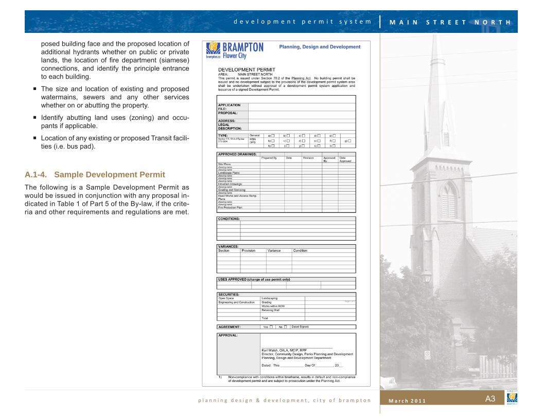
A.1-4. Sample Development PermitThe following is a Sample Development Permit as would be issued in conjunction with any proposal in-dicated in Table 1 of Part 5 of the By-law, if the crite-ria and other requirements and regulations are met.
M A I N S T R E E T N O R T H
p l a n n i n g d e s i g n & d e v e l o p m e n t , c i t y o f b r a m p t o n M a r c h 2 0 1 1
d e v e l o p m e n t p e r m i t s y s t e m
A4
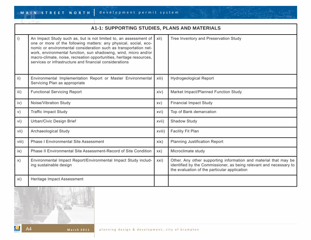
A1-1: SUPPORTING STUDIES, PLANS AND MATERIALS
i) An Impact Study such as, but is not limited to, an assessment of one or more of the following matters: any physical, social, eco-nomic or environmental consideration such as transportation net-work, environmental function, sun shadowing, wind, micro and/or macro-climate, noise, recreation opportunities, heritage resources, services or infrastructure and financial considerations
xii) Tree Inventory and Preservation Study
ii) Environmental Implementation Report or Master Environmental Servicing Plan as appropriate
xiii) Hydrogeological Report
iii) Functional Servicing Report xiv) Market Impact/Planned Function Study
iv) Noise/Vibration Study xv) Financial Impact Study
v) Traffic Impact Study xvi) Top of Bank demarcation
vi) Urban/Civic Design Brief xvii) Shadow Study
vii) Archaeological Study xviii) Facility Fit Plan
viii) Phase I Environmental Site Assessment xix) Planning Justification Report
ix) Phase II Environmental Site Assessment-Record of Site Condition xx) Microclimate study
x) Environmental Impact Report/Environmental Impact Study includ-ing sustainable design
xxi) Other. Any other supporting information and material that may be identified by the Commissioner, as being relevant and necessary to the evaluation of the particular application
xi) Heritage Impact Assessment
M A I N S T R E E T N O R T H
p l a n n i n g d e s i g n & d e v e l o p m e n t , c i t y o f b r a m p t o n M a r c h 2 0 1 1
d e v e l o p m e n t p e r m i t s y s t e m
A5
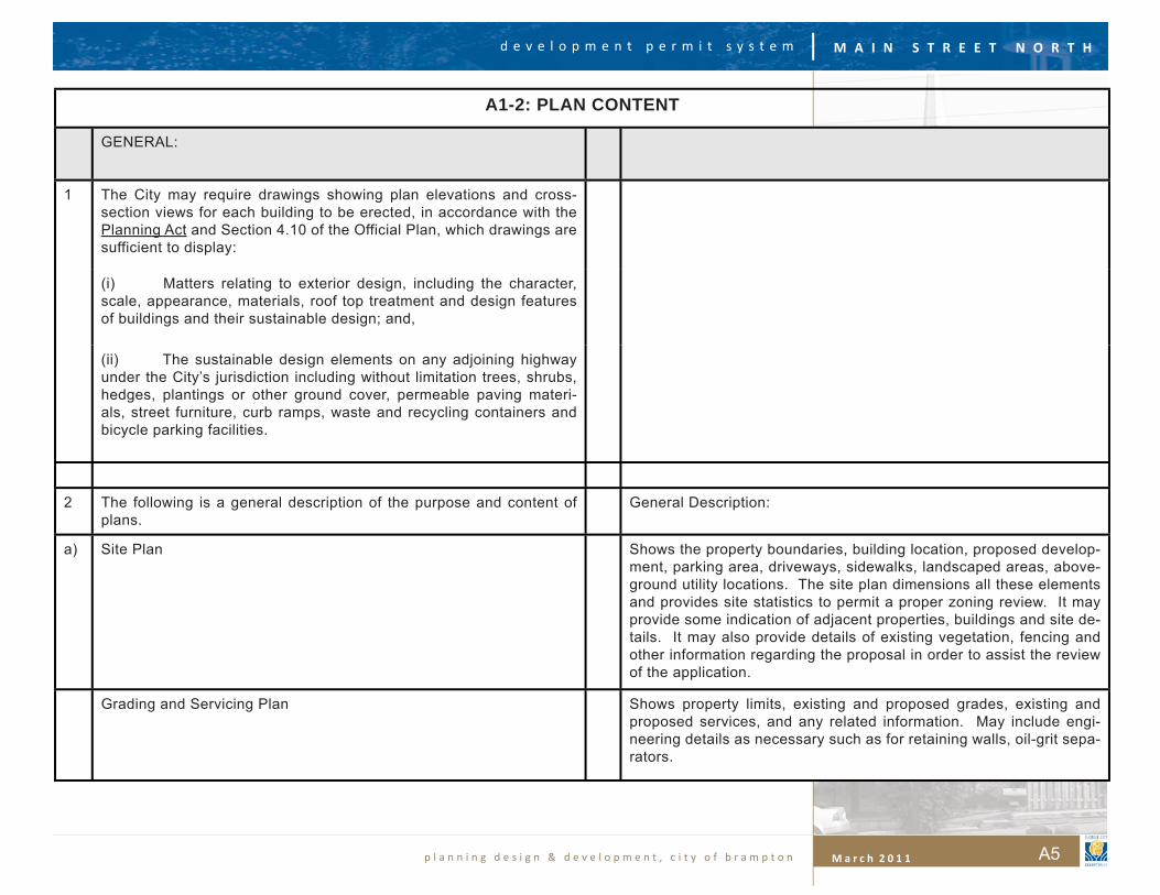
A1-2: PLAN CONTENT
GENERAL:
1 The City may require drawings showing plan elevations and cross-section views for each building to be erected, in accordance with the Planning Act and Section 4.10 of the Official Plan, which drawings are sufficient to display:
(i) Matters relating to exterior design, including the character, scale, appearance, materials, roof top treatment and design features of buildings and their sustainable design; and,
(ii) The sustainable design elements on any adjoining highway under the City’s jurisdiction including without limitation trees, shrubs, hedges, plantings or other ground cover, permeable paving materi-als, street furniture, curb ramps, waste and recycling containers and bicycle parking facilities.
2 The following is a general description of the purpose and content of plans.
General Description:
a) Site Plan Shows the property boundaries, building location, proposed develop-ment, parking area, driveways, sidewalks, landscaped areas, above-ground utility locations. The site plan dimensions all these elements and provides site statistics to permit a proper zoning review. It may provide some indication of adjacent properties, buildings and site de-tails. It may also provide details of existing vegetation, fencing and other information regarding the proposal in order to assist the review of the application.
Grading and Servicing Plan Shows property limits, existing and proposed grades, existing and proposed services, and any related information. May include engi-neering details as necessary such as for retaining walls, oil-grit sepa-rators.
M A I N S T R E E T N O R T H
p l a n n i n g d e s i g n & d e v e l o p m e n t , c i t y o f b r a m p t o n M a r c h 2 0 1 1
d e v e l o p m e n t p e r m i t s y s t e m
A6
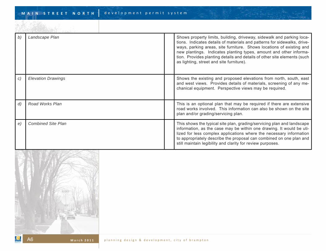
b) Landscape Plan Shows property limits, building, driveway, sidewalk and parking loca-tions. Indicates details of materials and patterns for sidewalks, drive-ways, parking areas, site furniture. Shows locations of existing and new plantings. Indicates planting types, amount and other informa-tion. Provides planting details and details of other site elements (such as lighting, street and site furniture).
c) Elevation Drawings Shows the existing and proposed elevations from north, south, east and west views. Provides details of materials, screening of any me-chanical equipment. Perspective views may be required.
d) Road Works Plan This is an optional plan that may be required if there are extensive road works involved. This information can also be shown on the site plan and/or grading/servicing plan.
e) Combined Site Plan This shows the typical site plan, grading/servicing plan and landscape information, as the case may be within one drawing. It would be uti-lized for less complex applications where the necessary information to appropriately describe the proposal can combined on one plan and still maintain legibility and clarity for review purposes.
M A I N S T R E E T N O R T H
p l a n n i n g d e s i g n & d e v e l o p m e n t , c i t y o f b r a m p t o n M a r c h 2 0 1 1
d e v e l o p m e n t p e r m i t s y s t e m
A7
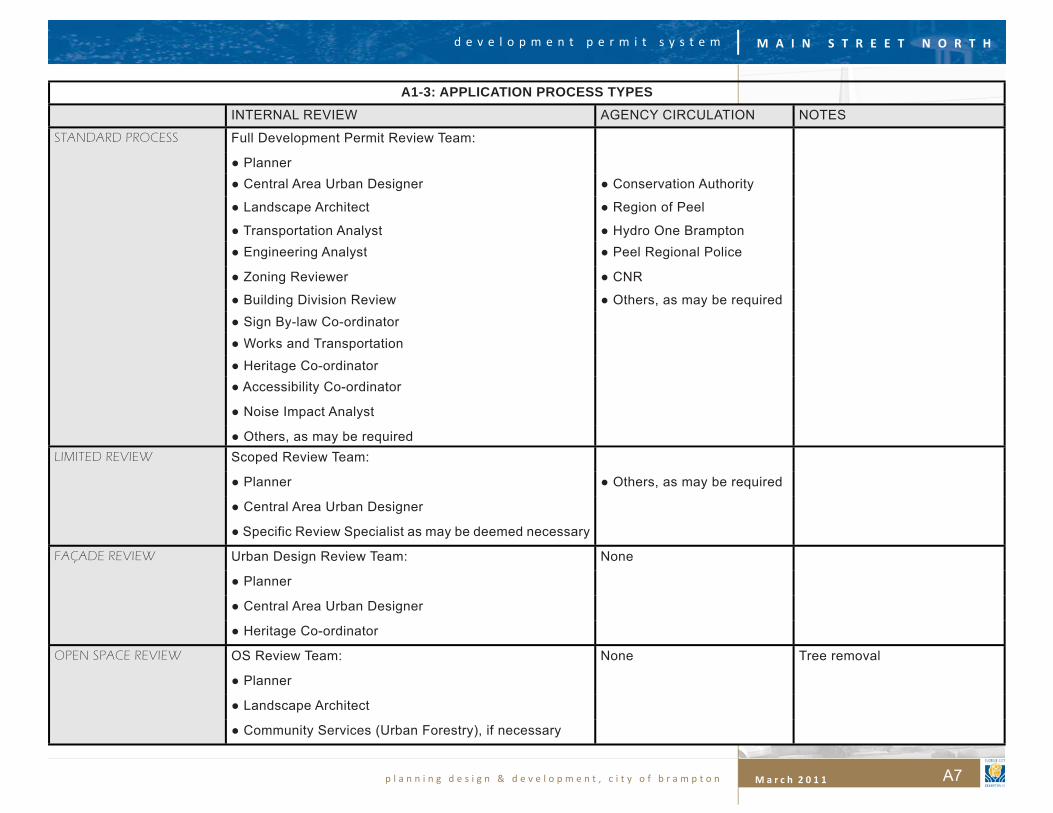
A1-3: APPLICATION PROCESS TYPESINTERNAL REVIEW AGENCY CIRCULATION NOTES
STANDARD PROCESS Full Development Permit Review Team:
● Planner● Central Area Urban Designer ● Conservation Authority
● Landscape Architect ● Region of Peel
● Transportation Analyst ● Hydro One Brampton● Engineering Analyst ● Peel Regional Police
● Zoning Reviewer ● CNR
● Building Division Review ● Others, as may be required● Sign By-law Co-ordinator● Works and Transportation
● Heritage Co-ordinator● Accessibility Co-ordinator
● Noise Impact Analyst
● Others, as may be requiredLIMITED REVIEW Scoped Review Team:
● Planner ● Others, as may be required
● Central Area Urban Designer
● Specific Review Specialist as may be deemed necessary
FAÇADE REVIEW Urban Design Review Team: None
● Planner
● Central Area Urban Designer
● Heritage Co-ordinator
OPEN SPACE REVIEW OS Review Team: None Tree removal
● Planner
● Landscape Architect
● Community Services (Urban Forestry), if necessary
M A I N S T R E E T N O R T H
p l a n n i n g d e s i g n & d e v e l o p m e n t , c i t y o f b r a m p t o n M a r c h 2 0 1 1
d e v e l o p m e n t p e r m i t s y s t e m
A8
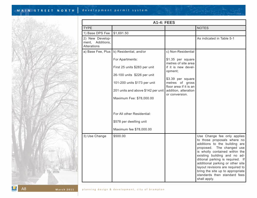
A1-4: FEESTYPE NOTES1) Base DPS Fee $1,691.502) New Develop-ment, Additions, Alterations
As indicated in Table 5-1
a) Base Fee, Plus b) Residential, and/or
For Apartments:
First 25 units $283 per unit
26-100 units $226 per unit
101-200 units $173 per unit
201 units and above $142 per unit
Maximum Fee: $78,000.00
For All other Residential:
$578 per dwelling unit
Maximum fee $78,000.00
c) Non-Residential
$1.35 per square metres of site area if it is new devel-opment;
$3.39 per square metres of gross floor area if it is an addition, alteration or conversion.
3) Use Change $500.00 Use Change fee only applies to those proposals where no additions to the building are proposed. The changed use is wholly contained within the existing building and no ad-ditional parking is required. If additional parking or other site layout revisions are required to bring the site up to appropriate standards then standard fees shall apply.
M A I N S T R E E T N O R T H
p l a n n i n g d e s i g n & d e v e l o p m e n t , c i t y o f b r a m p t o n M a r c h 2 0 1 1
d e v e l o p m e n t p e r m i t s y s t e m
A9
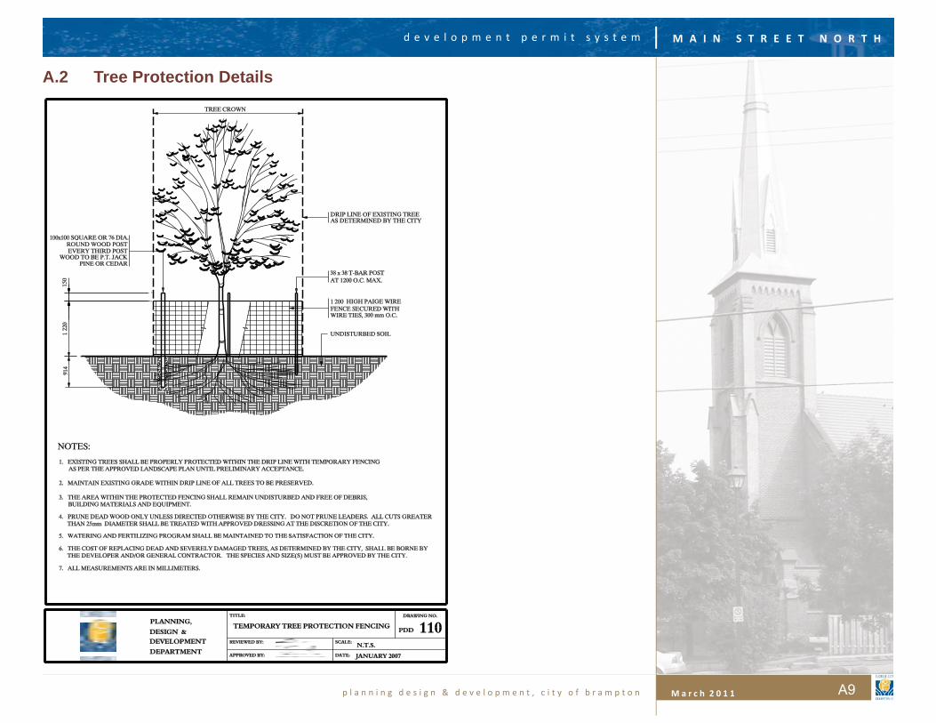
A.2 Tree Protection Details
M A I N S T R E E T N O R T H
p l a n n i n g d e s i g n & d e v e l o p m e n t , c i t y o f b r a m p t o n M a r c h 2 0 1 1
d e v e l o p m e n t p e r m i t s y s t e m
A10
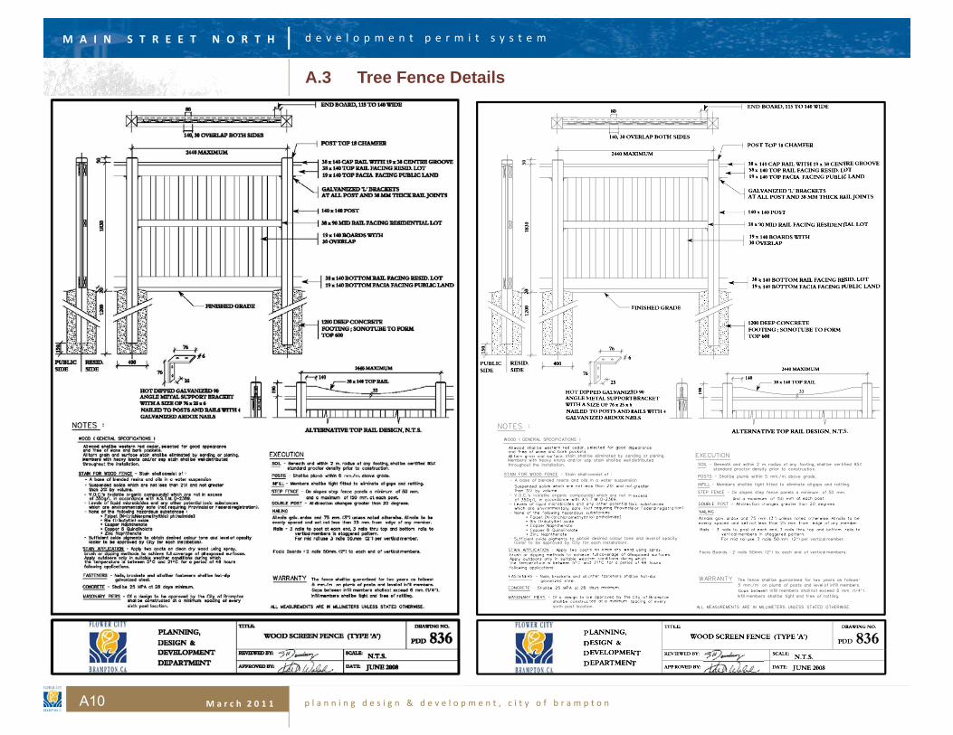
A.3 Tree Fence Details

M A I N S T R E E T N O R T H
p l a n n i n g d e s i g n & d e v e l o p m e n t , c i t y o f b r a m p t o n M a r c h 2 0 1 1
d e v e l o p m e n t p e r m i t s y s t e m
A11
A.4 Engineering, Grading and Servicing Requirements
Note: The following requirements are derived from the City’s Site Plan Manual. This Appendix will be revised from time to time if and when changes and revisions are made to the City’s Site Plan Manual. The applicant should contact the Development Ser-vices (Development Engineering) Division of the Planning, Design and Development to obtain the most up-to-date requirements.
A.4-1. Drawing RequirementsSite servicing and grading plans submitted to the Engineering and Development Services Division for approval must comply with City Standard #422 and the following items must appear on all plans. (Note: All plans are to be folded rather than rolled).
A.4-1.8. Stamped approval is required by the subdivision Consulting Engineer if the site is located within an un-assumed plan of subdivision. The subdivision Consulting Engineer must certify that the property line grading and stormwater management design conforms to the approved subdivision engineering plans and drainage design. All drawings and the stormwater management report must include the following:
If applicable, the following note: “The proposed lot grading and drainage is approved as being in conformity with the overall approved grading plans for the subdivision.”
Development Permit Application number, Project Name, Scale, Geodetic Benchmark, Municipal Address, Lot # and date of plan.
Site plan must be in metric scale.
Include a key plan, including the nearest major in-tersection, north arrow and legend.
Indicate any existing above ground utilities and trees within and around the site.
Indicate any existing 0.3 metre reserves across the frontage of the site (or fl ankage) and all road widening required by the relevant public authority.
Existing and proposed entrance width and curve radii to be dimensioned.
Location of all existing and proposed curb cuts and sidewalks must be identifi ed.
Existing curb cuts that are no longer required must be reinstated to O.P.S.D. or City standards, as re-quired. All existing driveway locations adjacent to the site or across the road must be shown.
Watercourse, swale, culvert, retaining wall, em-bankment, catch basin and other man-made or natural features on or adjacent to the site.
Any easements or right-of-ways are to be shown on plan and identifi ed as to the purpose and to whom the easement is in favour.
Finished fl oor elevations of buildings on adjacent properties must be indicated on the grading plans.
Existing road centre line and top of curb elevations of the street frontage must be shown at 20 metre intervals.
Indicate grades with arrows and percent slope on laneways, parking/landscape surfaces and drain-age swales.
A stamp from a Civil Engineer licensed to practice in the Province of Ontario.
M A I N S T R E E T N O R T H
p l a n n i n g d e s i g n & d e v e l o p m e n t , c i t y o f b r a m p t o n M a r c h 2 0 1 1
d e v e l o p m e n t p e r m i t s y s t e m
A12
A.4-2. General Notes
A.4-2.9. The following notes shall be included on all Grading and Servicing plans:
All the construction work for this project shall com-ply with the Standard Drawings and Specifi cations of the City of Brampton and the Ontario Provincial Standards and Specifi cations.
All surface drainage shall be collected and dis-charged at a location to be approved, prior to the issuance of a building permit.
Drainage of abutting properties shall not be ad-versely affected.
Proposed elevations along site property lines must match existing elevations.
A silt fence as per City Standard #406 must be placed around the perimeter of the site.
At all entrances to the site, the road curb and side-walk will be continuous through the driveway. The driveway grade will be compatible with the existing sidewalk and a curb depression will be provided at each entrance. Access construction as per City of Brampton Standard #237.
Sidewalk to be removed and replaced as per O.P.S.D. 310.010.
The portion of the driveway within the municipal boulevard must be paved with 40mm HL3 and 50mm HL8. Sub Base to be 150mm Granular “A” (or 130mm of 20mm crusher run limestone) and 300mm Granular “B” (or 225mm of 50mm crusher run limestone) compacted to 100% standard proc-tor density.
A utility clearance radius of 1.2 metres between the proposed driveway entrance curb return and all above ground utilities must be maintained.
Road occupancy/access permit must be obtained 48 hours prior to commencing any works within the municipal road allowance.
The service connection trench within the traveled portion of the road allowance shall be backfi lled in accordance with the requirements of the road occupancy/access permit application.
Within the City’s right-of-way, storm sewers and storm sewer connections must be concrete or approved equal with type “B” bedding through-out. The strength of the concrete pipe must be as per City Standard #341 and as follows; minimum 65-D for reinforced pipe and minimum ES for non reinforced pipe.
The minimum catch basin lead diameter allowed is 200mm.
Storm sewer pipes connecting to the City’s storm sewer shall not be smaller than 200mm.
All catch basin manholes and manholes with inlet control devices must have a minimum 0.3 metre sump and top, as per municipal standards.
Foundation drains shall not be connected to the storm sewer on sites with stormwater manage-ment control.
It is the responsibility of the design engineering consulting fi rm to ensure that an elevation detail of existing aerial plant is submitted when over-head cabling is present.
Cables shall not be less than 4.7 metres from the highest point of the fi nished pavement to the lowest point of the aerial cable directly above the pavement area to ensure clearances are met.
Provide this note if applicable – “The building sit-ed on this plan has been designed utilizing con-trolled fl ow roof drains in accordance with local municipal standards.”
M A I N S T R E E T N O R T H
p l a n n i n g d e s i g n & d e v e l o p m e n t , c i t y o f b r a m p t o n M a r c h 2 0 1 1
d e v e l o p m e n t p e r m i t s y s t e m
A13
Provide this note if applicable – “The owner’s is hereby notifi ed that the storm sewer proposed underneath the building is not a recommended practice of the City of Brampton – Planning, De-sign and Development Department. It is the sole responsibility of the owner in the event of any damages to the storm sewer or settlement of the building foundation.”
A.4-3. Lot Grading Criteria
A.4-3.10. Ensure that all drawings are consistently detailed between the servicing plan and the grading plan.
A.4-3.11. The maximum ponding depth permitted is 0.3 metres in parking areas, 1 metre in below grade loading docks and 0.5 metre in approved landscaped areas. Institutional sites shall not have ponding greater than 0.3 metres under system failure.
A.4-3.12. Municipal boulevards must be graded between 2% and 6% maximum.
A.4-3.13. Within the site, the following grading criteria is to be used:
a. Driveway grades 2% to 8%;
b. Other asphalt grades 0.5% to 8%;
c. Sodded areas 2% to 6%;
d. Landscaped berms to be a maximum 3 horizon-tal: 1 vertical grade (3:1);
e. Swales: min. 2% for institutional sites, min. 1% for commercial and industrial sites
A.4-3.14. Proposed elevations along all property lines must be compatible with the existing or proposed elevations of adjacent sites. Grading shall not extend onto adjacent properties unless written approval is obtained from the landowner previous to grading approval.
A.4-3.15. Existing ground elevations for 5 and 10 metres outside of property line, at 20 metre intervals, must be provided and the direction of drainage on the adjacent lands must be shown to the satisfaction of the Director of Engineering and Development Services.
A.4-3.16. If retaining walls are required the following criteria is to be followed:
A4-1.4.18
Land Use Co-efficientParks 0.25
Single and Semi-Detached 0.5
Multiple, Institutional 0.75
Commercial, Industrial, Road Right Of Way
0.9
Driveways / Parking lots (asphalt and gravel)
0.9
M A I N S T R E E T N O R T H
p l a n n i n g d e s i g n & d e v e l o p m e n t , c i t y o f b r a m p t o n M a r c h 2 0 1 1
d e v e l o p m e n t p e r m i t s y s t e m
A14
a. All retaining walls are to be concrete or heavy block concrete products; the use of timber will not be accepted. The backfi ll is to be compacted free draining granular material.
b. All retaining walls are to be designed, approved and stamped by a Consulting Engineer special-izing in structural engineering. The design must be accompanied by calculations clearly demon-strating that it is structurally satisfactory for the particular location and soil type.
c. The detailed drawing shall include the following notes:
i. The subject walls have been designed in accordance with accepted engineering principles
ii. The wall is suitable for the geotechnical condition of the site and for the type of loading.
d. The detail drawing shall show a weeping tile and incorporate a fi lter cloth envelope.
e. The installations are to be inspected during con-struction and certifi ed in writing by the Consulting Engineer as to conformity to design and suitabil-ity for the site conditions.
f. For retaining walls 0.6 metres in height or less, approved lightweight slabs using tiebacks will be permitted. A geogrid fabric or equivalent must be utilized as the tie back medium.
g. For retaining walls greater than 0.6 metres, the following systems may be utilized:
i. A concrete tie-back system,
ii. A heavy block system,
h. Protective fencing is required where the exposed retaining wall face height exceeds 0.6 metres. The structural stability of this wall must be able to withstand the extra force exerted by the fence as well as the earth loads.
i. Retaining walls shall not be located less than 1 metre from noise wall footings, except where absolutely necessary, at the discretion of the City and as designed and certifi ed by a structural engineer for both walls.
A.4-4. Storm Drainage
A.4-4.17. The internal storm sewer system shall be designed for the 2-year post development storm event.
A.4-4.18. The elevations along the property line should be carefully examined with respect to external drainage. The impact of external drainage must be addressed and provided for as required.
A.4-4.19. Site drainage shall be self-contained with only the municipal portion draining onto public roads.
A.4-4.20. Grading must be completed such that an overland fl ow route is maintained assuming all mechanical systems fail. This route must be clearly identifi ed on the drawings including the ultimate outlet of the overland fl ow route (i.e. watercourse or roadway). The maximum ponding depths must not be exceeded.
A.4-4.21. For storm sewers, the length, slope, size of pipe, pipe material, class of pipe and inverts at all connections must be shown.
A.4-4.22. Frost protection is required where cover is less than 1.2 metres from the pipe obvert to grade. Delineate extent of insulation on plan and provide a dimensioned detail.
M A I N S T R E E T N O R T H
p l a n n i n g d e s i g n & d e v e l o p m e n t , c i t y o f b r a m p t o n M a r c h 2 0 1 1
d e v e l o p m e n t p e r m i t s y s t e m
A15
A.4-4.23. Where utilities cross, a minimum clearance of 150mm must be provided between the top elevation of the lower pipe and the bottom elevation of the upper pipe.
A.4-4.24. As a general guide, one catch basin is required per 1,000 square metres of parking lot area depending upon the layout of the site.
A.4-4.25. The storm connection to the sewer in the street must have an invert above the spring line of the main sewer. A manhole is required if the storm connection lead is greater than one half the diameter of the street storm sewer.
A.4-4.26. Drop pipes must be provided where difference in obverts between incoming and outgoing pipes exceed 500mm as per City Standard #314.
A.4-4.27. The length of the sewer between the building and the fi rst manhole to which the building sewer connects shall not exceed 30 metres.
A.4-4.28. The storm sewer spacing between manholes shall be 90 metres.
A.4-4.29. The minimum fl ow angle allowed is 90 degrees.
A.4-4.30. Storm sewers proposed underneath buildings is not recommended. If proposed, a clause will be included in the site plan agreement in which the owner accepts sole responsibility in the event of any damages to the storm sewer or settlement of the building foundation.
A.4-4.31. Each property must have a separate connection to the municipal storm system as per the Ontario Building Code.
A.4-4.32. The control manhole or oil and grit separator should be located a minimum of 1.0 metre into the property.
A.4-4.33. Fee-in-lieu for quality control is available at the City’s discretion.
A.4-4.34. The following runoff co-effi cients shall be used:
A.4-5. Storm Water Management
A.4-5.35. Stormwater Management (SWM) Reports must be submitted with the grading and servicing plans if required. The design criteria will be determined by the Engineering and Development Services Division and varies depending on the location of the site. The design criteria must be clearly stated in the report.
A.4-5.36. Stormwater management design must incorporate the City of Brampton IDF curves Std. #343.
A.4-5.37. Sites will use an inlet time of 10 minutes.
A.4-5.38. SWM reports utilizing computer modeling must be done with an accepted model by the City of Brampton with a 2 to 4 hour duration storm and a maximum 10-minute time step.
M A I N S T R E E T N O R T H
p l a n n i n g d e s i g n & d e v e l o p m e n t , c i t y o f b r a m p t o n M a r c h 2 0 1 1
d e v e l o p m e n t p e r m i t s y s t e m
A16
A.4-5.39. The SWM Report must clearly state which method is being used to determine peak fl ow and storage required (i.e. rational method, OTTHYMO, etc.). Provide calculations indicating what the allowable discharge from the site is, what volume of storage is required and what volume of storage is provided.
A.4-5.40. The SWM report must defi ne an orifi ce size. This orifi ce design must be correctly identifi ed and detailed on the drawings. An orifi ce tube will also be required. The following criteria shall be used for the design of the restrictor pipe downstream of the orifi ce plate as a permanent stormwater quantity control for on-site storage to satisfy the Conservation Authority.
A.4-5.41. For with an Oil/Grit Separator is proposed:
An orifi ce plate, sized in accordance with the recommendation of the SWM report, shall be in-stalled in the Control Manhole upstream of the Oil/Grit Separator.
A restrictor pipe, with manufacturer’s standard pipe size equal to or one size larger than the ori-fi ce plate design, shall be installed between the Control Manhole and the Oil/Grit Separator locat-ed 1.0 metre from the Street line within the prop-erty.
The maximum length of the restrictor pipe shall be 5.0 metres. A manhole shall be installed at any change in pipe size within the site.
Downstream of the Oil/Grit Separator, continue with the required design storm sewer sizing or a minimum 200mm diameter storm sewer, which-ever is greater.
A.4-5.42. For sites without an Oil/Grit Separator:
An orifi ce plate, sized in accordance with the recommendation of the SWM report, shall be in-stalled in the Control Manhole.
A restrictor pipe, maximum 5.0 metres in length with manufacturer’s standard pipe size equal to or one size larger than the orifi ce plate design, shall be installed downstream of the Control Man-hole. If the restrictor pipe is less than 200mm in diameter, the restrictor pipe shall extend 1.0 me-tre into the City right-of-way and increase to a minimum 200mm diameter pipe size with an ec-centric increaser.
Note: If the design of the orifi ce plate diameter is the same size of a manufactured standard pipe, an orifi ce plate will not be required upstream of the restrictor pipe.
The orifi ce control device must be installed on the outlet pipe from the control manhole and conform to City of Brampton Standards. The control man-hole must have a minimum 0.3m sump.
If permitted, roof top storage details including control device type/ model (vandal proof), maxi-mum depth, maximum fl ow, volume and number of notches per drain must be included in the SWM Report and shown on the Servicing Plan.
Ensure that the required ponding areas are shown on the plan, and indicate ponding volume and elevation.
Ponding (if permitted) is allowed in the following areas:
ii. Rooftops (150mm max.)
iii. Paved areas and parking lots (300mm max.)
iv. Landscaped Industrial areas (500mm max.)(Only if the Parks Planning Divi-sion has approved the location. It is the
M A I N S T R E E T N O R T H
p l a n n i n g d e s i g n & d e v e l o p m e n t , c i t y o f b r a m p t o n M a r c h 2 0 1 1
d e v e l o p m e n t p e r m i t s y s t e m
A17
Applicant’s responsibility to obtain this approval in writing.)
v. Below grade loading dock (1000mm max.)
The ponding depths on the site must be reviewed under the following two conditions:
i. A properly functioning stormwater man-agement system.
ii. A failed stormwater management system, where the system has become sur-charged or blocked.
The resultant site ponding shall not exceed City of Brampton’s specifi cations (as outlined in sec-tion 4.2.2.).
Quality control for all site plans shall be designed to the M.O.E.’s enhanced level of protection (Lev-el 1).
Ensure the Oil/Grit Separator is shown and prop-erly detailed on the downstream side of control MHs (where required).
Specify the name of manufacturer and model number. Fee-in-lieu for quality control is available at the City’s discretion.
The fi nished fi rst fl oor elevation at each building must be compatible to the road and the adjacent buildings. (I.e. the F.F.E. should be a minimum 0.15 metres higher than the maximum ponding depth). One hundred-year basement protection must be achieved.
No foundation drains are to be connected to the storm sewer on sites with stormwater manage-ment control.
A.4-6. Condominium Townhouses
A.4-6.43. Condominium townhouse projects must be designed and built to the City of Brampton’s Subdivision Design Standards and Specifi cations.
A.4-6.44. If the site is a plan of condominium or cooperative housing project, the owner will have the option of posting the full security value for the project or may post the securities as follows:
Prior to execution of the development permit agreement, the developer, in addition to the normal security for work on public lands and landscaping and fencing, would post an initial engineering se-curity of $10,000 and sign a pre-servicing agree-ment.
The developer could then proceed to construct the common element works in accordance with ap-proved engineering plans without posting addition-al security up to the time the road is constructed to base course asphalt.
Once the road has been constructed to base course asphalt, before any building permits are issued, the developer’s Consulting Engineer shall certify to the City that the completed works have been constructed in accordance with approved en-gineering plans.
The developer would then be required to post full engineering securities for the value of the remain-ing common element works to be completed plus 10% maintenance for works completed. This could take the form of applying existing engineering se-curities that might otherwise be available for re-duction to the remaining common element works.
M A I N S T R E E T N O R T H
p l a n n i n g d e s i g n & d e v e l o p m e n t , c i t y o f b r a m p t o n M a r c h 2 0 1 1
d e v e l o p m e n t p e r m i t s y s t e m
A18
A.4-6.45. The developer’s consulting engineer shall be required to provide certifi cation that the top of foundation wall has been constructed as per the approved plans. This certifi cation shall include the as constructed elevation of the foundation wall and shall be sent to the City of Brampton immediately after construction of the foundation wall.
A.4-7. Engineering and Development Approval Process
A.4-7.46. If submissions are deemed incomplete in terms of the applicant’s failure to provide all the necessary documents, then the department will return the submission.
A.4-7.47. Two copies of the required drawings and reports shall be submitted with the initial submission for review.
A.4-7.48. The drawings will be returned with redline comments, if required, to the applicant who submits the plans to the Engineering and Development Services Division.
A.4-7.49. No redlined revisions will be accepted. All drawings shall be fully completed by the applicant and all notes and approvals shall be included on the drawings prior to the approval by the Engineering and Development Services Division.
A.4-7.50. At the time of approval, the Engineering and Development Services Division requires seven copies of all site servicing and grading plans and two copies of the SWM report and related calculations.
A.4-7.51. All plans, reports, and calculations shall be stamped, signed and dated by a Civil Engineer licensed to practice in Ontario prior to Engineering and Development Services Division approval.
A.4-7.52. The following are the current applicable security amounts required by the Engineering and Development Services Division:
$25 per linear metre of site frontage
$15,000 lot grading deposit for sites less than or equal to two (2) hectares in size.
$20,000 lot grading deposit for sites greater than two (2) hectares in size.
$300 per square metre of retaining wall or toe wall face.