Embed Size (px)
Citation preview

Appendix B-6
Mechanical Equipment Design Calculation

Detailed Design Study on Water Supply and Sewerage System for Astana City Final Report
B-6-1
APPENDIX B.6 Mechanical Equipment Calculation
1. Design Conditions
(1) Design Flow
M3/day M3/hour M3/min M3/sec
Design Maximum Daily Flow
136,000 5,666.7 94.44 1.574
Design Maximum Hourly Flow
200,000 8,333.3 138.89 2.315
(2) Influent Sewage Characteristics
Influent sewage characteristics for designing treatment facilities are as follows.
Primary Sedimentation Effluent
ITEM Characteristic value Removal
Rates Effluent Removal Rates Effluent
Total Removal Rates
BOD 170 mg/l 30% 119mg/l 83.2% 20mg/l 88%
SS 210 mg/l 40% 125mg/l 84.1% 20mg/l 90%
2. Inflow Tank
2.1 Inlet Chamber Gate
(1) Design Conditions
Design Maximum Hourly Flow: 200,000 m3/day
Electric Motor Sluice Gate
Quantity: 1
(2) Specifications
Type: Electric Motor Sluice Gate
Diameter: Φ1,400
Power Requirement: 2.2 kW
Quantity: 1
2.2 Bypass Gate
Bypass Gate shall be installed before the temporary pump station for diversion of sewage.
(1) Design Conditions
Detailed Design Study on Water Supply and Sewerage System for Astana City Final Report
B-6-2
Design Maximum Hourly Flow: 100,000 m3/day
Electric Motor Sluice Gate
Quantity: 1
(2) Diameter
Flow velocity is assumed to be 1.0 m/sec with the diameter of the gate is 2.0m.
1.157 m3/sec /π × 2.02 ÷ 4 = 0.37 m/sec
(3) Specifications
Type: Electric Motor Sluice Gate
Diameter: φ2,000㎜
Power Requirement: 5.5 kW
Quantity: 1
3. Influent Pump Station
3.1 Chamber Gate
(1) Design Conditions
Design Maximum Hourly Flow: 200,000 m3/day
Motor Driven
Quantity: 3
(2) Specifications
Type: Motor Driven
Diameter: W1.68m×H2.0m
Power Requirement: 0.4 kW
Quantity: 3
3.2 Fine Screen
The principal role of screening is to remove fine materials from influent sewage.
(1) Design Conditions
Automatic Cleaning Bar Screening
Design Maximum Hourly Flow: 200,000 m3/day
Opening of Screen: 6mm
(2) Scale of Chamber
1.68m(Width)×2.0m(Depth)
(3) Specifications
Type: Mechanically Cleaning Bar Screen

Detailed Design Study on Water Supply and Sewerage System for Astana City Final Report
B-6-3
Power Requirement: 0.75 kW
Quantity: 3
3.3 Influent Pumps
The principal role of main pumps is to transfer sewage from reservoir to grit chamber.
(1) Design Conditions
Vertical Shaft Type Mixed Flow Pump
Design Maximum Hourly Flow: 200,000 m3/day (138.89 m3/min)
Quantity: Three Large-Scale Pumps (One is for standbys), Two Medium-Scale Pumps
(2) Capacities of Pumps
Large-Scale Pumps: 54m3/min
Medium-Scale Pumps: 27m3/min
Total Capacity: 54×2+27×2=162 m3/min
(138.89 m3/min < 162 m3/min ・・・ OK)
(3) Diameter
Flow velocity is designed to be between 1.5 m/sec and 3.0 m/sec.
Large-Scale Pumps: (1.5~3)/min54m
1463
=619~876㎜ → φ700㎜
Medium-Scale Pumps: (1.5~3)/min27m
1463
=438~619㎜ → φ450㎜
(4) Total Pump Head
Actual Pump Head H1
Pump Pit +338.1
-) Inlet Chamber +348.92
10.82 m
Head Loss in Pipe H2 2.5 m
Total Head H3 H3 = H1 + H2 = 10.82 + 2.5 = 13.32 m → 15 m
(5) Electric Motor Power
D= α)(1
γrHQ0.163 ××××
Large-Scale Pumps:
= (1+0.15)0.8
115540.163 ×××
= 189.8 → 200kW

Detailed Design Study on Water Supply and Sewerage System for Astana City Final Report
B-6-4
Medium-Scale Pumps
= (1+0.15)
0.77115270.163 ×××
= 98.6 → 110kW
(6) Specifications
Large-Scale Pumps
Type: Vertical Shaft Type Mixed Flow Pump
Discharge Capacity: 54 m3/min
Total Head: 15 m
Power Requirement: 200 kW
Quantity: 2 (1 Standby)
Medium-Scale Pumps
Type: Vertical Shaft Type Mixed Flow Pump
Discharge Capacity: 27 m3/min
Total Head: 15 m
Power Requirement: 110 kW
Quantity: 2
3.4 Sump Drainage Pumps
Floor Drain Pumps remove miscellaneous sewage in drain pits .
(1) Design Conditions
Removal Submersible Pump
Quantity: 2
(2) Capacities of Pumps
0.3 m3/min
(3) Total Pump Head
Actual Pump Head H1
Drain Pit +334.1
-) Piping Level +346.0
11.9 m
Head Loss in Pipe H2 2 m
Total Head H3 H3 = H1 + H2 = 11.9 + 2.0 = 13.9 m → 15 m
(4) Specifications
Type: Removal Submersible Pump

Detailed Design Study on Water Supply and Sewerage System for Astana City Final Report
B-6-5
Discharge Capacity: 0.3 m3/min
Total Head: 15 m
Power Requirement: 1.5 kW
Quantity: 2
3.5 Temporary Pumps
Temporary Pumps deliver sewage from temporary pump station to grit chamber during the rehabilitation works of existing influent pump station.
(1) Design Conditions
The capacity should meet the present inflow volume of 100,000 m3/day.
Removal Submersible Pump
Quantity: 3
(2) Capacities of Pumps
Q = 60243100,000
×× = 23.15 → 25 m3/min
(3) Diameter
Flow velocity is assumed to be 1.5~3.0 m/sec.
(1.5~3)/分25m
1463
= 596~421 → φ500 mm
(4) Total Pump Head
Actual Pump Head H1
Pump Pit +339.00
-) Piping Level +348.93
9.93 m
Head Loss in Pipe H2: 1.8 m
Total Head H3: H3 = H1 + H2 = 9.93 + 1.8 = 11.73 m → 14 m
(5) Power Requirement
D = α)(1γ
rHQ0.163 ××××
= (1+0.15)0.7
114250.163 ×××
= 93.725 → 110kW
(6) Specifications
Type: Removal Submersible Pump
Detailed Design Study on Water Supply and Sewerage System for Astana City Final Report
B-6-6
Discharge Capacity: 25 m3/min
Total Head: 14 m
Power Requirement: 110 kW
Quantity: 3
3.6 Exhaust Fan
Exhaust fan ventilates inside the reservoir.
(1) Ventilation Capacity
(π × 242/4) × 5 mH ÷ 2 × 3 times/hr × 1/60 = 56.52 m3/min
(2) Specifications
Type: Centrifugal Fan
Air Flow Capacity: 60 m3/min
Pressure: 0.15kpa
Power Requirement: 0.75 kW
Quantity: 1
3.7 Air Intake Fan (1)
Air Intake Fan (1) intakes air in the underground screen chamber.
(1) Ventilation Capacity
(π × 242/4) × 5 mH ÷ 2 × 3 times/hr × 1/60 = 56.52 m3/min
(2) Specifications
Type: Centrifugal Fan
Air Flow Capacity: 60 m3/min
Pressure: 0.15kpa
Power Requirement: 0.75 kW
Quantity: 1
3.8 Air Intake Fan (2)
Air Intake Fan (2) intakes air in the motor room.
(1) Ventilation Capacity
Heat yielded by motors should be considered.
18 × 24 × 12 mH × 3 times/hr × 1/60 = 259.2 m3/min
(2) Specifications
Type: Centrifugal Fan
Air Flow Capacity: 260 m3/min

Detailed Design Study on Water Supply and Sewerage System for Astana City Final Report
B-6-7
Pressure: 0.15kpa
Power Requirement: 3.7 kW
Quantity: 1
3.9 Air Intake Fan (3)
Air Intake Fan (3) intakes air in the underground pump room.
(1) Ventilation Capacity
(π × 242/4) × 5 mH ÷ 2 × 3 times/hr × 1/60 = 56.52 m3/min
(2) Specifications
Type: Centrifugal Fan
Air Flow Capacity: 60 m3/min
Pressure: 0.15kpa
Power Requirement: 0.75 kW
Quantity: 1
4. Grit Chamber
4.1 Inlet Gate
Inlet gates are installed for separate each chamber respectively.
Design Conditions
Design Maximum Hourly Flow: 200,000 m3/day
Quantity: 2
Scales of Gates
Tangential velocity is to be designed about 1.0 m/sec/
2.31 m3/sec/(1.2 x1.0 x 2)=0.8m/sec
(3) Specifications
Type: Electric Motor Sluice Gate
Scale: 1.2 m x 1.0 m
Power Requirement: 1.5 kW
Quantity: 2
4.2 Bypass Gate
(1) Design Conditions
Design Maximum Hourly Flow: 200,000 m3/day
Quantity: 1
(2) Diameter

Detailed Design Study on Water Supply and Sewerage System for Astana City Final Report
B-6-8
Flow velocity is assumed to be 1.0 m/sec with the diameter of the gate is 2.0m.
1.157 m3/sec /π × 1.52 ÷ 4 = 0.66 m/sec
(3) Specifications
Type: Electric Motor Sluice Gate
Scale: 1.5mDia
Power Requirement: 2.2 kW
Quantity: 1
4.3 Grit Collectors
Grit collectors collect and assemble grit to the center of the chamber with mixing.
Design Conditions
Type of Grit Collectors: Vortex-Type
Quantity: 2
Scales of Grit Chambers
4.4 Grit Pumps
Grit Pumps remove grit from the bottom of grit chamber.
(1) Design Conditions
Type of Pumps: Discharge Pump
Volume of grit is estimated form 0.0005 to 0.05 m3 per 1,000 m3 of sewage.
(2) Capacities of Pumps
136,000 m3/day×10000.05~0.0005
=0.068~6.8 m3/day
Pumps remove daily maximum grit in two hours. The grit density is expected to be 5 %.
=××× 5
1002set60hr/day8.6
2~0.068
0.0057~0.57 m3/min
The diameter of pump should be larger than φ80. And the normal discharge capacity is 0.45~0.70 m3/min. The capacity of pumps shall be 0.5m3/min × 2.
(3) Total Pump Head
Actual Pump Head H1
Grit Chamber +348.8
-) Piping Level +352.7
3.9 m
Head Loss in Pipe H2
2.9 m

Detailed Design Study on Water Supply and Sewerage System for Astana City Final Report
B-6-9
Total Head H3
H3 = H1 + H2 = 3.9 + 2.9 = 6.8 m → 8 m
(4) Specifications
Type: Discharge Pump
Diameter: φ80 mm
Discharge Capacity: 0.5 m3/min
Power Requirement: 3.7 kW
Quantity: 2
4.5 Grit Scrubber
Grit Separator cleans and separates grit conveyed by grit pumps.
(1) Design Conditions
Volume of grit is 0.068~6.8 m3/day
(2) Separation Capacity
Separator shall be operated for one hour automatically two times a day.
=×× 2set2hr/day
8.6times 1~0.068
0.034~1.7 m3/hr
The capacity of the grit separator shall be 2.0 m3/hr.
(3) Specifications
Type: Screw Grit Conveyor
Separation Capacity: 2.0 m3/hr
Power Requirement: 1.5kw (conveyor)
2.2kw ×2 (mixer)
Quantity: 1
4.6 Scum Screen
Scum Separator separates scum conveyed from primary sedimentation tanks.
(1) Design Conditions
Disk Screen Type
(2) Specifications
Type: Disc Screen
Scale: 0.5 m3/min. or over
Clear Spacing between Bars: 3.0 mm
Power requirement: 0.4kw

Detailed Design Study on Water Supply and Sewerage System for Astana City Final Report
B-6-10
Quantity: 1
5. Primary Sedimentation Tank
5.1 Sludge Collectors
(1) Design Conditions
Type of Sludge Collectors: Circumference Drive
Quantity: 8
(2) Scale of Sedimentation Tanks
28 m (diameter) x 3.5 (depth) x 8
(3) Specifications
Type: Circumference Drive
Scale: dia28 m
Power Requirement: 1.5 kW
Quantity: 8
5.2 Primary Sludge Pumps
Primary Sludge Pumps remove primary sludge from the bottom of primary sedimentations and transfer the sludge to gravity thickener.
(1) Design Conditions
Sludge Volume: 655 m3/day
Type of Pumps: Non-Clogging Sludge Pump
Dia-100 x 1.0 m3/min
Quantity: 2 (2 Standby)
(2) Capacities
Operation Time: 655 m3 /min x1/60 x 1/2 = 5.46 hr
(3) Total Pump Head
Actual Pump Head H1
Primary Sedimentation +347.41
-) Distribution Level +345.13
-2.28 m
Head Loss in Pipe H2: 9.9m
Total Head H3
H3 = H1 + H2 = -2.28 + 9.9= 7.62 m → 9 m
(3) Specifications

Detailed Design Study on Water Supply and Sewerage System for Astana City Final Report
B-6-11
Type: Non-Clogging Pump
Discharge Capacity: 1.0 m3/min
Total Head: 9.0 m
Power Requirement: 5.5 kW
5.3 Scum Pumps
(1) Scum Inflow
Q = 1.838 BH3/2 (m3/sec)
B: Width of Weir (m)
H: Overflow Depth (m)
= 1.838 × 1.5 × 0.023/2 × 60 = 0.4678 m3/min
(2) Pump Discharge Capacity
0.4678 × 1 pond = 0.4678 hr → 0.5m3/min
(3) Total Pump Head
Actual Pump Head H1
Scum Pit +346.0
-) Piping Level +351.0
5.2 m
Head Loss in Pipe H2: 6.4m
Total Head H3
H3 = H1 + H2 = 5.2 + 6.4 = 11.6 m → 12 m
(4) Specifications
Type: Non-Clogging Pump
Discharge Capacity: 0.5 m3/min
Diameter: φ80
Total Head: 12.0 m
Power Requirement: 3.7 kW
5.4 Exhaust Fan
Exhaust fan ventilates the screen chamber.
(1) Ventilation Capacity
(π × 72/4) × 5.5 mH × 3 times/hr × 1/60 = 10.58 m3/min
(2) Specifications
Type: Centrifugal Fan

Detailed Design Study on Water Supply and Sewerage System for Astana City Final Report
B-6-12
Air Flow Capacity: 12 m3/min
Pressure: 0.15kpa
Power Requirement: 0.2 kW
Quantity: 1
6. Blower House
6.1 Air Blower
Blower is designed to supply air to aeration device in Aeration Tank.
6.2 Air Requirements
(1) Actual Oxygen Requirements (AOR)
Db = A x (Ci - Co)Qn x 10-3}=8,078(kgO2/day)
A: Oxygen Requirement for unit BOD Removal(0.6kgO2/kgBOD)
Ci: BOD of Effluent Sewage(119mg/L)
Co: BOD of Treated Water (20mg/L)
Qn: Effluent Flow (136,000m3/day)
Dn = C x (Ck1×10-3×Qn)-(Ck2×10-3×Qn)
-{(a×93×10-3+b×90×10-3-c×0.333×MLSS×10-3)
×Qn×Nx}=13,407(kgO2/day)
C: Oxygen Requirements for Nitrification (4.57kgO2/kgN)
Ck1: K1-N Concentration of Influent Sewage (35mg/L)
Ck2: K1-N Concentration of Effluent Water (5mg/L)
A: Gross Yield Coefficient of Dissolved BOD (0.5gMLSS/gBOD)
b: Gross Yield Coefficient of Suspended Solid (0.95gMLSS/gBOD)
c: Reduce Coefficient of Endogenous Respiration of Activated Sludge Organisms( 0.4L/d)
Nx: Nitrogen Concentration of Waste Activated Sludge (8%)
De = B×0.333×Qn×(MLSS×10-3×0.8)= 7,246(kgO2/day)
B: Oxygen Requirements of Endogenous Respiration of Unit MLSS (0.1kgO2/kgMLSS)
Actual Oxygen Requirements (AOR)
AOR = Db+Dn+De
= 8,078+13,407+7,246
= 28,731㎏-O2/day
Db: Oxygen Requirements for Organic Oxidation (㎏-O2/day)

Detailed Design Study on Water Supply and Sewerage System for Astana City Final Report
B-6-13
Dn: Oxygen Requirements for Nitrification (㎏-O2/day)
De: Oxygen Requirement for Endogenous Respiration(㎏-O2/day)
(2) Standard Oxygen Requirements (SOR)
SOR = AOR・Csw・r/{1.024(T2-T1)・α・(β・Csw・r-CA)}×760/P
SOR: Oxygen Supply Capacity at 20 Centigrade Degrees (㎏-O2/day)
AOR: Actual Oxygen Requirements(㎏-O2/day)
Csw: Concentration of Oxygen Saturation in at 20 Centigrade Degrees(8.84㎎/L)
r: Calibration Coefficient of Cs in accordance with Diffuser Depth
1/2×(10.332+4/10.332+1) = 1.19
H: Diffuser Depth( Depth - 0.3 = 4.0 - 0.3 = 3.7m)
Cs : Concentration of Oxygen Saturation in at T Centigrade Degrees(8.84㎎/L)
T1: Standard Water Temperature (20℃)
T2: Mixed Liquid Temperature (20℃)
CA: DO Concentration of Mixed Liquid (1.5㎎/L)
α: Calibration Coefficient of K1a (0.83)
β: Calibration Coefficient of Oxygen Saturation Temperature(0.95)
P: Atmosphere Pressure(760㎜ Hg)
SOR = 28,731×8.84×1.19/{1.024(20-20)×0.83(0.95×8.84×1.19-1.5)}×760/760=39,957㎏-O2/day
Gs=SOR/Ea×ρ×Ow/100=1,024,620 Nm3/day
Temperature Calibration
1,024,620 Nm3/day×273+20℃/273=1,099,683.7 m3/day
SOR: 39,957㎏-O2/day
Ea: Oxygen Transfer Efficient (13%)
ρ: Air Density (1.293kgAirNm3)
Ow: Oxygen Content in Air (0.232kgO2/kg)
6.3 Blower Capacity
(1) Design Conditions
① Quantity: 5 (2 standby)
1,099,683.7 m3/day÷24÷60÷3units=254.5m3/min・unit
(2) Diameter
Sanction speed is designed to be 20~30m/sec.

Detailed Design Study on Water Supply and Sewerage System for Astana City Final Report
B-6-14
D= 3020
255146~
= 521~425
For sanction φ450, for dischargeφ400
(3) Electric Motor Power
Design Conditions
Air Feed Volume: 255 m3/min
Sanction Pressure Plg: -200 mmAq
Discharge Pressure P2g: 4,800 mmAq
Sanction Absolute Pressure P1 = 10,333 – 200 = 10,133 mmAq
Discharge Absolute Pressure P2 = 10,333 + 4,800 = 15,133 mmAq
(Atmospheric Pressure: 10,333 mmAq)
Sanction Air Volume Q1 = 1013310333255× = 260 m3/min
Insulating Electric Motor Power L1
L1 =
−
−×
×−
1333,10133,15
4.114.1120,6
333,10255 4.114.1
= 179kw
Required Electric Motor Power L2
L2 = 70.0
179 = 256kw
Total Insulating Efficiency: 70%
The minimum temperature is assumed to be minus –20oC (Mean temperature in winter is –16.1deg according to Master Plan of Astana City by JICA).
L2 =
−×
20273293256 = 296kw
Electric Motor Power L2
L0 = 296×(1+0.05)=311kw → 315kw
(4) Specifications
Type: Multistage Turbo Blower
Diameter: Sanction φ450 × Dischargeφ400
Supplied Air Flow: 255m3/min
Pressure: 50kpa
Power Requirement: 315 kW

Detailed Design Study on Water Supply and Sewerage System for Astana City Final Report
B-6-15
Quantity: 3 (2 standby)
6.4 Clear Water Supply Pump
Design Conditions
Clear Water Supply Volume: 0.052m3/min/unit
0.052m3/min×3units =0.156m3/min → 0.3m3/min
(2) Specifications
Type: Volute Pump
Discharge Capacity: 0.3 m3/min
Diameter: φ65
Total Head: 20 m
Power Requirement: 2.2 kW
Quantity: 1 (1 standby)
7. Secondary Sedimentation Tank
7.1 Sludge Collectors
(1) Design Conditions
Type of Sludge Collectors: Circumference Drive
Quantity: 12
(2) Scale of Sedimentation Tanks
28 m (diameter) × 3.5 (depth) × 12
(3) Specifications
Type: Circumference Drive
Scale: dia28 m
Power Requirement: 1.5 kW
Quantity: 12
8. Return Sludge Pumps
8.1 Return Sludge Pumps
Return Sludge Pumps return activated sludge from the bottom of secondary sedimentations to reactors.
(1) Design Conditions
① Pump capacities should meet 100% of daily maximum sewage flow.
② Type of Pumps: Vertical Shaft Type Mixed Flow Pump
Quantity: 3 (2 standby)

Detailed Design Study on Water Supply and Sewerage System for Astana City Final Report
B-6-16
(2) Capacities
Q=60min24hour1003units
100%136,000×××
×
=31.48m3/min → 32m3/min
(3) Diameter
D=VQ
146 =1.5~3
14632
=477~674 → φ500
(4) Total Pump Head
Actual Pump Head H1
Sanction Level +345.08
-) Inlet Pipe for Distribution Tank +349.0
3.92 m
Head Loss in Pipe H2: 1.8m
Total Head H3
H3 = H1 + H2 = 3.92 + 1.8 = 5.72 m → 6 m
(5) Power Requirement
D=0.75
16320.163 ×××(1+0.15)
=47.99 → 55 kW
(6) Specifications
Type: Vertical Shaft Type Mixed Flow Pump
Discharge Capacity: 32 m3/min
Diameter: φ500
Total Head: 6 m
Power Requirement: 55 kW
Quantity: 3 (2 standby)
8.2 Waste Sludge Pump
Waste Activated Sludge Pumps transfer waste activated sludge from the bottom of secondary sedimentations to the Waste Activated Sludge Storage Tank.
(1) Design Conditions
Type of Pumps: Non-Clogging Pump
Sludge Volume: 3,322 m3/day

Detailed Design Study on Water Supply and Sewerage System for Astana City Final Report
B-6-17
Pump Discharge Rate: 4.7 m3/min
Quantity: 1 (standby 1)
(2) Capacities
Pump Operation Time
3,322/4.2m3/min×1/60 = 11.78 hours
(3) Diameter
D = VQ
146 = 1.5~3
1467.4
= 183~258 → φ200
(4) Total Pump Head
Actual Pump Head H1
Sanction Level +345.08
-) Inlet Pipe Level +344.3
-0.78 m
Head Loss in Pipe H2: 9.1m
Total Head H3
H3 = H1 + H2 = -0.78 + 9.1 = 8.32 m → 10 m
(5) Power Requirement
D=0.45
1104.70.163 ×××(1+0.15)
=19.58 → 22 kW
(6) Specifications
Type: Non-Clogging Pump
Discharge Capacity: 4.7 m3/min
Diameter: 200mm
Total Head: 10 m
Power Requirement: 22kW
Quantity: 1 (1 standby)
8.3 Sump Drainage Pumps
(1) Design Conditions
Removal Submersible Pump
Quantity: 1 (1 Standby)
(2) Capacities of Pumps

Detailed Design Study on Water Supply and Sewerage System for Astana City Final Report
B-6-18
0.3 m3/min
(3) Total Pump Head
Actual Pump Head H1
Drain Pit +343.4
-) Piping Level +348.35
4.95 m
Head Loss in Pipe H2: 2 m
Total Head H3: H3 = H1 + H2 = 4.95 + 2.0 = 6.95 m → 10 m
(4) Specifications
Type: Removal Submersible Pump
Discharge Capacity: 0.3 m3/min
Total Head: 10 m
Power Requirement: 1.5 kW
Quantity: 1 (1 Standby)
9 Discharge Pump Station
9.1 Discharge Pump
(1) Design Conditions
Vertical Shaft Volute Type Mixed Flow Pump
Design Maximum Hourly Flow: 200,000 m3/day (138.89 m3/min)
Quantity: Three Large-Scale Pumps (One is for standbys), Two Medium-Scale Pumps
(2) Capacities of Pumps
Large-Scale Pumps: 54m3/min
Medium-Scale Pumps: 27m3/min
Total Capacity: 54×2+27×2=162 m3/min
(138.89 m3/min < 162 m3/min … OK)
(3) Diameter
Flow velocity is designed to be between 1.5 m/sec and 3.0 m/sec.
Large-Scale Pumps: (1.5~3)/min54m
1463
=619~876㎜ → φ800㎜
Medium-Scale Pumps: (1.5~3)/min27m
1463
=438~619㎜ → φ600㎜
(4) Total Pump Head

Detailed Design Study on Water Supply and Sewerage System for Astana City Final Report
B-6-19
Actual Pump Head H1
Pump Pit +340.2
-) Outlet Pipe +349.0
8.8 m
Head Loss in Pipe H2: 4.22m
Total Head H3
H3 = H1 + H2 = 8.8 + 4.22= 13.02 m → 15 m
(5) Electric Motor Power
D= α)(1γ
rHQ0.163 ××××
Large-Scale Pumps:
= (1+0.15)0.8
115540.163 ×××
= 189.8 → 200kW
Medium-Scale Pumps
= (1+0.15)0.8
115270.163 ×××
= 94.89 → 110kW
(6) Specifications
Large-Scale Pumps
Type: Vertical Shaft Volute Type Mixed Flow Pump
Discharge Capacity: 54 m3/min
Total Head: 15 m
Power Requirement: 200 kW
Quantity: 2 (1 Standby)
Medium-Scale Pumps
Type: Vertical Shaft Volute Type Mixed Flow Pump
Discharge Capacity: 27 m3/min
Total Head: 15 m
Power Requirement: 110 kW
Quantity: 2
9.2 Inlet Chamber Gate
(1) Design Conditions

Detailed Design Study on Water Supply and Sewerage System for Astana City Final Report
B-6-20
Design Maximum Hourly Flow: 200,000 m3/day
Electric Motor Sluice Gate
Quantity: 1
(2) Specifications
Type: Electric Motor Sluice Gate
Diameter: φ1,500㎜
Power Requirement: 3.7 kW
Quantity: 1
9.3 Temporary Pumps
Temporary Pumps deliver treated water during the repairing works of existing effluent pump station.
(1) Design Conditions
The capacity should meet the present inflow volume of 100,000 m3/day.
Removal Submersible Pump
Quantity: 3
(2) Capacities of Pumps
Q = 60243
100,000××
= 23.15 → 25 m3/min
(3) Diameter
Flow velocity is assumed to be 1.5~3.0 m/sec.
(1.5~3)/分25m
1463
= 596~421 → φ500 mm
(4) Total Pump Head
Actual Pump Head H1
Pump Pit +340.10
-) Piping Level +349.00
8.90 m
② Head Loss in Pipe H2: 2.87 m
③ Total Head H3: H3 = H1 + H2 = 8.9 + 2.87 = 11.77 m → 15 m
(5) Power Requirement
D = α)(1γ
rHQ0.163 ××××
= (1+0.15)0.7
115250.163 ×××
Detailed Design Study on Water Supply and Sewerage System for Astana City Final Report
B-6-21
= 100.4 → 110kW
(6) Specifications
Type: Removal Submersible Pump
Discharge Capacity: 25 m3/min
Total Head: 15 m
Power Requirement: 110 kW
Quantity: 3
9.4 Air Intake Fan (1)
Air Intake Fan (1) intakes air in the underground motor room.
(1) Ventilation Capacity
Heat value of electric motors shall be taken into consideration.
18 × 24 × 12mH × 3 times/hr × 1/60 = 259.2 m3/min
(2) Specifications
Type: Centrifugal Fan
Air Flow Capacity: 260 m3/min
Pressure: 0.15kpa
Power Requirement: 3.7 kW
Quantity: 1
9.5 Air Intake Fan (2)
Air Intake Fan (2) intakes air in the underground pump room.
(1) Ventilation Capacity
Heat yielded by motors should be considered.
(π × 242 / 4) × 5 mH ÷ 2 × 3 times/hr × 1/60 = 56.52 m3/min
(2) Specifications
Type: Centrifugal Fan
Air Flow Capacity: 60 m3/min
Pressure: 0.15kpa
Power Requirement: 0.75 kW
Quantity: 1
10. Gravity thickener
10.1 Thickened Sludge Collector

Detailed Design Study on Water Supply and Sewerage System for Astana City Final Report
B-6-22
Thickened Sludge Collectors bring together sediment sludge from the bottom of in sludge thickener to sludge pit.
(1) Design Conditions
Type of Sludge Collectors: Center Drive
Quantity: 2, that is correspond to the number of sedimentation tanks.
(2) Scale of Sedimentation Tanks
20 m (diameter) x 3.5 (depth) x 2
(3) Specifications
Type: Center Drive
Scale: dia20 m
Power Requirement: 0.75 kW
Quantity: 2
10.2 Thickened Sludge Pumps
Thickened Sludge Pumps transfer thickened sludge from the bottom of thickeners to thickened sludge reservoirs.
(1) Design Conditions
Sludge Volume: 236 m3/day
Type of Pumps: Non-Clogging Pump
Diameter: 100 mm (prevention against clogging considered)
Discharge Capacity: 1.0 m3/min
Quantity: 1 (standby 1)
(2) Capacities
Operation Time
236/1m3/min×1/60×1/1=3.93hour
Diameter
D=VQ
146 =1.5~3
1461
=84.3~146→ φ100
Power Requirement
D=0.4
1510.163 ×××(1+0.15)
=2.34 → 3.7 kW
(3) Total Pump Head
Actual Pump Head H1
Water Level of Thickener +345.4

Detailed Design Study on Water Supply and Sewerage System for Astana City Final Report
B-6-23
-) Pipe Level +345.8
0.4 m
Head Loss in Pipe H2: 3.6m
Total Head H3: H5 = H1 + H2 = 0.4 + 3.6 = 4.0m → 5.0 m
(4) Specifications
Type: Non-Clogging Pump
Discharge Capacity: 1.0 m3/min
Diameter: 100mm
Total Head: 5 m
Power Requirement: 3.7 kW
Quantity: 1 (1 standby)
10.4 Exhaust Fan
Exhaust fan ventilates the sludge pump room.
(1) Ventilation Capacity
(π × 72/4) × 5.5 mH × 3 times/hr × 1/60 = 10.58 m3/min
(2) Specifications
Type: Centrifugal Fan
Air Flow Capacity: 12 m3/min
Pressure: 0.15kpa
Power Requirement: 0.2 kW
Quantity: 1
11. Digester &&&& Pump House
11.1 Sludge Pump
(1) Design Conditions
Mixing Method: Pump Mechanical Stirring
Digester Capacity: 1,950 m3/tank
(2) Mixing Capacity
Q=1,950 m3×4 times/24×1/60=5.42 → 5.5 m3/min
(3) Total Pump Head
Actual Pump Head H1
Water Level of Digester +351.3
-) Pipe Level +355.5

Detailed Design Study on Water Supply and Sewerage System for Astana City Final Report
B-6-24
4.2 m
Head Loss in Pipe H2: 6.7 m
Total Head H3: H5 = H1 + H2 = 4.2 + 6.7 = 10.9 m → 12.0 m
(4) Specifications
Type: Non-Clogging Pump
Diameter: 250 mm
Discharge Capacity: 5.5 m3/hr
Head: 12 m
Power Requirement: 22 kW
Quantity: 1 (1 standby)
11.2 Gas Holder
(1) Design Conditions
Generated Gas Volume: 9,839 m3
Storage Time: 6 hours
(2) Tank Capacity
9,839 m3×64/24×2 units=1,229 m3 → 1,300 m3
(3) Specifications
Type: Wet Type Gas Holder
Treatment Capacity: 1,300 m3/hr
Quantity: 2
11.3 Desulfurizer
(1) Design Conditions
Treatment Gas Volume: 10,968 m3/d = 457 m3/hr
= 7.62 m3/min = 0.1269 m3/sec
Type: Wet Type Desulfurizer
(2) Treatment Capacity
10,968 m3/d×1/24 = 457 m3/hr → 460 m3/hr
(3) Diameter
Velocity of Gas Flow = 0.04~0.05m/sec
D=√4×Q÷π×V
=√4×0.1269÷π×0.04~0.05
=2.01~1.798

Detailed Design Study on Water Supply and Sewerage System for Astana City Final Report
B-6-25
→ 2.0 m/sec
(4) Height
Absorption Reaction Time: 1 min
H=Q×t÷π/4×D2=V×60×t
=0.05×60×1.02=3.0m
(5) Water Supply Volume
q=a×Q (m3/min)
a : Gas-Liquid Contact Ratio 0.8
Q : Gas Generation Volume.62m3/min
q=0.8×7.62 =6.093 m3/min
(6) Specifications
Type: Wet Type Desulfurizor
Treatment Capacity: 460 m3/hr
Quantity: 1
11.4 Air Intake Fan
Air Intake Fan intakes air in the underground pump room and piping room.
(1) Ventilation Capacity
(π × 72/4) × 18.0mH × 3 times/hr × 1/60 = 34.62 m3/min
4.1 × 3.1 × 13.0mH × 2 × 3 times/hr × 1/60 = 16.52 m3/min
= 51.143 m3/min
(2) Specifications
Type: Centrifugal Fan
Air Flow Capacity: 26 m3/min
Power Requirement: 1.5 kW
Quantity: 2 (2 standby)
12. Sludge Treatment Building
12.1 Mechanical Thickener
Mechanical Sludge Thickening Equipment thickens activated sludge transferred from secondary sedimentation tanks.
(1) Design Conditions
Operation Time: 24 hours per day
Type: Screw Press
Sludge Volume: 3,322 m3/day

Detailed Design Study on Water Supply and Sewerage System for Astana City Final Report
B-6-26
Thickening Capacity: 75m3/hour (25m3/m2/hr x 3.0 m2/unit)
(2) Quantity
3,322m3/day×(7/7)×(1/24)/75m3/hr
=1.85 → 2 units
(3) Specifications
Type: Screw Press
Thickening Capacity: 75m3/hour
Power Requirement: 1.5 kW + 0.75 kW + 0.75 kW
Quantity: 2 (1 standby)
12.2 Waste Sludge Feed Pumps
Sludge Supply Pumps transfer activated sludge from sludge reservoirs to thickening equipment.
(1) Design Conditions
Sludge Supply Volume: 3,322 m3/d = 138.4 m3/hour
Type of Pumps: Progressing Cavity Pump (quantitative advantages considered)
Discharge Capacity: 50%~150% of Dewatering Capacity (taking into consideration of operational fluctuation)
Quantity: 2 (standby 1)
(2) Discharge Capacity
Thickener capacity 3,322 m3/d
Q=24
3,322 5.1~5.0××21=34.4~103.8m3/hr
(3) Total Head
20m for Progressing Cavity Pump
(4) Specifications
Type: Progressing Cavity Pump (gear changeable)
Discharge Capacity: 34~104m3/hr
Diameter: 200mm
Total Head: 20 m
Power Requirement: 30 kW
Quantity: 2 (1 standby)
12.3 Thickened Sludge Pumps
Thickened Sludge Pumps transfer thickened sludge from the thickened sludge reservoirs to digesters.
(1) Design Conditions
Sludge Volume: 548 m3/day

Detailed Design Study on Water Supply and Sewerage System for Astana City Final Report
B-6-27
Type of Pumps: Non-Clogging Pump
Diameter: 100 mm × 1.0 m3/min (prevention against clogging considered)
Quantity: 1 (standby 1)
(2) Capacities
Operation Time
548/1m3/min×1/60 = 9.13 hour
(3) Total Pump Head
Actual Pump Head H1
Water Level of Digester +355.0
-) Pipe Level +341.2
13.8 m
Head Loss in Pipe H2: 7.1 m
Total Head H3: H5 = H1 + H2 = 13.8 + 7.1 = 20.9 m → 22.0 m
(4) Specifications
Type: Non-Clogging Pump
Discharge Capacity: 1.0 m3/min
Diameter: 100mm
Total Head: 22 m
Power Requirement: 11 kW
Quantity: 1 (1 standby)
12.4 Polymer Tanks
Chemical Dissolving Tanks reserve and dissolve chemicals supplied by supply equipment.
(1) Design Conditions
Chemical Feeding Rate: 1.0%
Chemical Dissolving Concentration: 0.2%
Plural Dissolving Tanks: 2 (alternative operation)
Capacity: Unit capacity meets 2 hour dewatering capacity
(2) Chemical Volume
1007day/week
1.0%7day/week/day16,612㎏・ds×
××=166.1㎏/day
(3) Capacities of Tanks
V=Q×10-3×Tt×C100=166.1×10-3×
24hour/day2hour
×0.2100

Detailed Design Study on Water Supply and Sewerage System for Astana City Final Report
B-6-28
=6.92m3 → 7m3
(4) Specifications
Type: Vertical Cylindrical Tank
Capacity: 7.0m3
Power Requirement: 3.7 kW
Quantity: 2
12.5 Polymer Feeder
Chemical Supply Equipment reserve chemical and supply water and chemical to chemical dissolving tanks determinately and continuously.
(1) Design Conditions
Chemical (Flocculant) Density: 0.6
Supply Time: 15min
Chemical Dissolving Concentration: 0.2%
(2) Supply Volume
Q=V×100C×t1×r1×103
=7.0×1000.2×151×0.61×103 =1.56m3/min → 2000 cc/min
V: Chemical Dissolving Tank Capacity 7.0m3
Q: Chemical Supply Volume L/min
C: Chemical Dissolving Concentration 0.2%
t: Supply Time 15min
r: Chemical (Flocculants) Density 0.6
(3) Specifications
Type: Positive Displacement Supplier
Supply Capacity: 2000 cc/min
Power Requirement: 0.4 kW
Quantity: 2
12.6 Polymer Feed Pumps
Chemical Supply Pumps supply chemical dissolved liquid to dewatering equipment determinately.
(1) Design Conditions
Type of Pumps: Progressing Cavity Pump (quantitative advantages considered)
Sludge Volume: 3,322 m3/day
Detailed Design Study on Water Supply and Sewerage System for Astana City Final Report
B-6-29
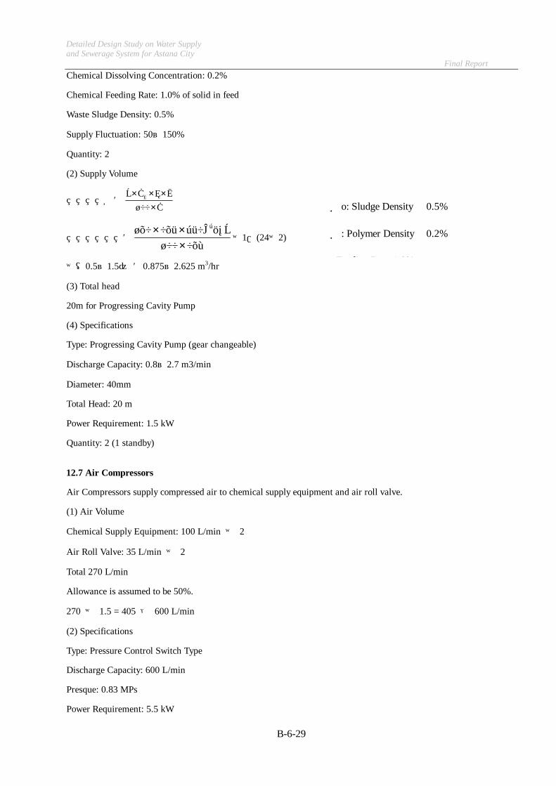
Chemical Dissolving Concentration: 0.2%
Chemical Feeding Rate: 1.0% of solid in feed
Waste Sludge Density: 0.5%
Supply Fluctuation: 50~150%
Quantity: 2
(2) Supply Volume
Q=C100KQCr O
××××
=0.2100
/hr350m0.51.0 3
×××
×1/(24×2)
×(0.5~1.5) =0.875~2.625 m3/hr
(3) Total head
20m for Progressing Cavity Pump
(4) Specifications
Type: Progressing Cavity Pump (gear changeable)
Discharge Capacity: 0.8~2.7 m3/min
Diameter: 40mm
Total Head: 20 m
Power Requirement: 1.5 kW
Quantity: 2 (1 standby)
12.7 Air Compressors
Air Compressors supply compressed air to chemical supply equipment and air roll valve.
(1) Air Volume
Chemical Supply Equipment: 100 L/min × 2
Air Roll Valve: 35 L/min × 2
Total 270 L/min
Allowance is assumed to be 50%.
270 × 1.5 = 405 → 600 L/min
(2) Specifications
Type: Pressure Control Switch Type
Discharge Capacity: 600 L/min
Presque: 0.83 MPs
Power Requirement: 5.5 kW
Co: Sludge Density 0.5%
C: Polymer Density 0.2%
r F di R 1 0%

Detailed Design Study on Water Supply and Sewerage System for Astana City Final Report
B-6-30
Quantity: 1 (1 standby)
12.8 Dewatering Machines
Sludge Dewatering Machines dewater digested sludge from digesters.
(1) Design Conditions
Operation Time: 24 hours per day
Type: Screw Press
Feed Digested Sludge Volume: 16,452 m3/day (3.0% of sludge density)
Thickening Capacity: 450kg/hour
(2) Quantity
16,452 m3/day×(7/7)×(1/24)/450kg/hr
=1.52 → 2 units
(3) Specifications
Type: Screw Press Dewatering Machine
Thickening Capacity: 450 kg/hr
Power Requirement: 3.7 kW +1.5 kW
Quantity: 2 (1 standby)
12.9 Sludge Feed Pumps
Sludge Feed Pumps transfer digested sludge from digester to sludge dewatering machines.
(1) Design Conditions
Sludge Supply Volume: 450kg/hour/3.0/100×10-3=15m3/hour
Type of Pumps: Progressing Cavity Pump (quantitative advantages considered)
Discharge Capacity: 50%~150% of Dewatering Capacity (taking into consideration of operational fluctuation)
Quantity: 3 (standby 1)
(2) Discharge Capacity
Dewatering capacity15m3/hr: Q=15 x (0.5~1.5)=7.5~22.5 kg/hr
(3) Total Head
20m for Progressing Cavity Pump
(4) Specifications
Type: Progressing Cavity Pump (gear changeable)
Discharge Capacity: 7.5 ~22.5 m3/hr
Diameter: 125mm
Total Head: 20 m

Detailed Design Study on Water Supply and Sewerage System for Astana City Final Report
B-6-31
Power Requirement: 7.5 kW
Quantity: 2 (1 standby)
12.10 Polymer Tanks
Chemical Dissolving Tanks reserve and dissolve chemicals supplied by supply equipment.
(1) Design Conditions
Chemical Feeding Rate: 1.4%
Chemical Dissolving Concentration: 0.2%
Plural Dissolving Tanks: 2 (alternative operation)
Capacity: Unit capacity meets 2 hour dewatering capacity
(2) Chemical Volume
1007day/week
1.4%7day/week/day16,452㎏・ds×
××=230.3㎏/day
(3) Capacities of Tanks
V=Q×10-3×Tt×C100=230.3×10-3×
24hour/day2hour
×0.2100
=9.56m3 →10m3
(4) Specifications
Type: Vertical Cylindeical Tank
Capacity: 10m3
Power Requirement: 5.5 kW
Quantity: 2
12.11 Polymer Feeder
Chemical Supply Equipment reserve chemical and supply water and chemical to chemical dissolving tanks determinately and continuously.
(1) Design Conditions
Chemical (Flocculant) Density: 0.6
Supply Time: 15min
Chemical Dissolving Concentration: 0.2%
(2) Supply Volume
Q=V×100C×t1×r1×103
=10×1000.2×151×0.61×103 =2.2m3/min → 4000cc/min
V: Chemical Dissolving Tank Capacity 10m3
Detailed Design Study on Water Supply and Sewerage System for Astana City Final Report
B-6-32
Q: Chemical Supply Volume L/min
C: Chemical Dissolving Concentration 0.2%
t: Supply Time 15min
r: Chemical (flocculant) Density 0.6
(3) Specifications
Type: Positive Displacement Supplier
Supply Capacity: 4000cc/min
Power Requirement: 0.4 kW
Quantity: 2
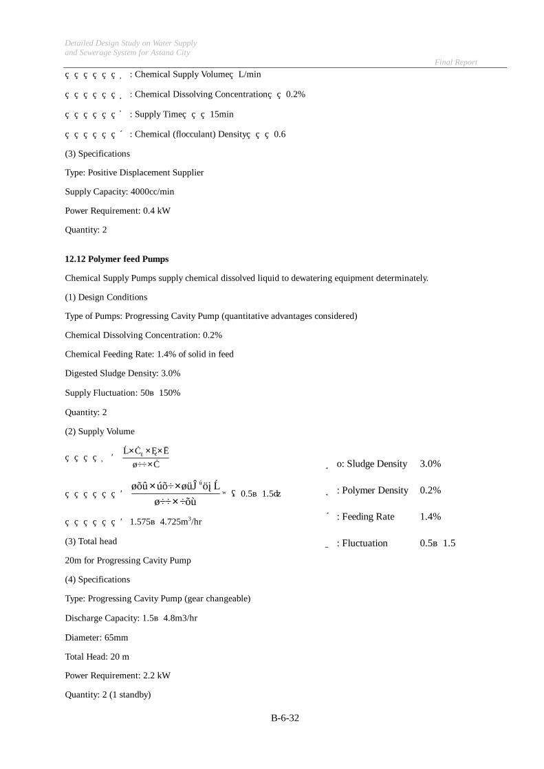
12.12 Polymer feed Pumps
Chemical Supply Pumps supply chemical dissolved liquid to dewatering equipment determinately.
(1) Design Conditions
Type of Pumps: Progressing Cavity Pump (quantitative advantages considered)
Chemical Dissolving Concentration: 0.2%
Chemical Feeding Rate: 1.4% of solid in feed
Digested Sludge Density: 3.0%
Supply Fluctuation: 50~150%
Quantity: 2
(2) Supply Volume
Q=C100KQCr O
××××
=0.2100
/hr15m3.01.4 3
×××
×(0.5~1.5)
=1.575~4.725m3/hr
(3) Total head
20m for Progressing Cavity Pump
(4) Specifications
Type: Progressing Cavity Pump (gear changeable)
Discharge Capacity: 1.5~4.8m3/hr
Diameter: 65mm
Total Head: 20 m
Power Requirement: 2.2 kW
Quantity: 2 (1 standby)
Co: Sludge Density 3.0%
C: Polymer Density 0.2%
r: Feeding Rate 1.4%
K: Fluctuation 0.5~1.5

Detailed Design Study on Water Supply and Sewerage System for Astana City Final Report
B-6-33
12.13 Polymer Container
(1) Quantity
Required Capacity:
Thickener: 166.12 kg/day
Dewatering Machine: 230.33 kg/day
Total: 396.45 kg/day
y)0.5(densit/day0.39645m3
=0.7929m3/day
Storage Period: 10 days
Quantity:
ainer)1.0m3(Cont10×/day0.7929m3=7.929
→ 1.0 m3 × 8
12.14 Sewage Pumps
Miscellaneous Used Water Drain Pumps drain water from reservoir to grit chamber.
(1) Design Conditions
Miscellaneous Used Water Volume
Thickener Effluent :3,007 m3/day
Dewatering Machine Effluent: 474 m3/day
Total 3,481 m3/day
Type of Pumps: Non-Clogging Pump
Quantity: 2 (1 Standby)
(2) Capacities of Pumps
2460×3,481
=2.417m3/日
→ 3.0 m3/min
(3) Total Pump Head
Actual Pump Head H1
Reservoir Level +341.2
-) Piping Level +350.2
9.0 m

Detailed Design Study on Water Supply and Sewerage System for Astana City Final Report
B-6-34
Head Loss in Pipe H2: 6.6 m
Total Head H3: H3 = H1 + H2 = 9.0 + 6.6 = 15.6 m → 17 m
(4) Specifications
Type: Non-Clogging Pump
Discharge Capacity: 3.0 m3/min
Diameter: 200 mm
Total Head: 17 m
Power Requirement: 22 kW
Quantity: 1 (1 Standby)
12.15 Scrubber
Scrubber is designed to be Biological type.
(1) Newly Supply Water
Newly Supply Water Ration: 1.5~2.0L/Nm3
Water Quantity: Q = 273/293×90 m3/min×1.5~2.0
=125.82~167.76 L/min
→170 L/min
12.16 Odor Fan
Odor fan ventilates the sludge treatment building.
(1) Ventilation Capacity
90 m3/min
(2) Specifications
Type: Centrifugal Fan
Air Flow Capacity: 90 m3/min
Pressure: 2.5kpa
Power Requirement: 5.5 kW
Quantity: 1
12.17 Deodorization Volume
(1) Sludge Dewatering Machine
(2 m3 × (1-0.5)×2 times/hr)÷60min = 0.033→2m3/min・unit
3 units×2 m3/min=6m3/min
(2) Mechanical Thickener
(2 m3 × (1-0.5)×2 times/hr)÷60min = 0.033→2m3/min・unit

Detailed Design Study on Water Supply and Sewerage System for Astana City Final Report
B-6-35
3 units×2 m3/min=6m3/min
(3) Excess Sludge Reservoir
4.7 m3/min(Excess Sludge Pump Capacity)×1.1 =5.17m3/min
(4) Thickened Sludge Reservoir
(21 m2 ×3 m3/m2・hr)÷60 min=1.05→2m3/min・unit
2units×2m3/分・unit =4 m3/min
(5) Digested Sludge Reservoir
(27 m2 ×3 m3/m2・hr)÷60 min=1.35→2m3/min・unit
2units×2 m3/min・unit =4 m3/min
(6) Sludge Cake Hopper
(15 m3 ×(1-0.5) ×7 times/hr)÷60 min=0.875 m3・unit→2m3/min・unit
6units×2 m3/min・unit =12 m3/min
(7) Sludge Cake Conveyor
(5 m3 ×7 times/hr)÷60 min=0.58 m3・unit→2m3/min・unit
3units×2 m3/min・unit =6 m3/min
(8) Miscellaneous Used Water Reservoir
(56 m3 ×3 m3/m3・hr)÷60 min=2.8 →2.8 m3/min・unit
2.8 units×1 m3/min・unit =2.8 m3/min
(9) Gravity Thickener
(314m2×3 m3/m3・hr)÷60 min=15.7 m3/min・unit
15.7×2 unit → 31.4 m3/min・unit
(10) Digester Sludge Distribution
(4.5×3.5×3m3/m3・hr)÷60 min=0.788 m3/min
3units×2 m3/min・unit =6 m3/min
(1)~(10) Total = 83.37 m3/min
→ 90 m3/min
12.18 Elutriation Water Pumps
Water Elutriation Pumps elutriate offensive odor generated from sludge treatment process.
(1) Design Conditions
Horizontal Shaft Volute Type Pump
Quantity: 1 (1 Standby)
(2) Capacities of Pumps

Detailed Design Study on Water Supply and Sewerage System for Astana City Final Report
B-6-36
According to calculation for deodorization equipment the feed water capacity is assumed to be 170 l/min.
(3) Total Pump Head
Actual Pump Head H1
Reservoir Level +340.0
-) Inlet Pipe for Deodorizer +348.0
8.0 m
Head Loss in Pipe H2: 6.0m
Head Loss in Auto Strainer H3: 1.0m
Discharge Pressure H4: 10.0m
Total Head H5: H5 = H1 + H2 + H3 +H4 = 8.0 + 6.0 +1.0 + 10.0 = 25 m
(4) Specifications
Type: Horizontal Shaft Volute Type Pump
Discharge Capacity: 0.17 m3/min
Total Head: 25 m
Power Requirement: 3.7 kW
Quantity: 1 (1 Standby)
Desulfurization Equipment Feed Pumps feed water for desulfurization equipment as elutriation usage.
12.19 Treated Water Supply Unit
Treated Water Supply Unit feed water for Sludge Suction Pipe and grit chamber.
(1) Design Conditions
Pressure Tank Type
Quantity: 1 (1 Standby)
(2) Capacities of Pumps
Total capacity of pumps designed to be ten times of grit volume.
The volume of grit is assumed to be 0.034~1.7m3/hr.
0.034~1.7m3/hr × 10 × 1/60 = 0.0057~0.28 m3/min
→ 0.3 m3/min
(3) Total Pump Head
Actual Pump Head H1
Reservoir Level +340.0
-) Pipe Level +352.2
12.2 m
Head Loss in Pipe H2: 10.5m

Detailed Design Study on Water Supply and Sewerage System for Astana City Final Report
B-6-37
Head Loss in Auto Strainer H3: 1.0m
Total Head H4: H5 = H1 + H2 + H3 = 12.2 + 10.5 +1.0 = 23.7 m → 25 m
(4) Specifications
Type: Pressure Tank Type
Discharge Capacity: 0.3 m3/min
Total Head: 25 m
Power Requirement: 3.7 kW
Quantity: 1 (1 Standby)
12.20 Desulfurize Pumps
Desulfurization Equipment Feed Pumps feed water for desulfurization equipment as elutriation usage.
(1) Design Conditions
Horizontal Shaft Volute Type Pump
Quantity: 1 (1 Standby)
(2) Capacities of Pumps
According to calculation for digester equipment the feed water capacity is assumed to be 6.1 m3/min.
(3) Total Pump Head
Actual Pump Head H1
Reservoir Level +340.0
-) Pipe Level +348.5
8.5 m
Head Loss in Pipe H2: 2.4m
Head Loss in Auto Strainer H3: 1.0m
Discharge Pressure H4: 10.0m
Total Head H5: H5 = H1 + H2 + H3 +H4 = 8.5 + 2.4 +1.0 + 10.0 = 21.9m → 23m
(4) Specifications
Type: Horizontal Shaft Volute Type Pump
Discharge Capacity: 6.1 m3/min
Total Head: 23 m
Power Requirement: 45 kW
Quantity: 1 (1 Standby)
12.21 Water Supply Unit
Water Supply Unit feed water for Polymer Tank and Influent Pump Discharge Pump.

Detailed Design Study on Water Supply and Sewerage System for Astana City Final Report
B-6-38
(1) Design Conditions
Pressure Tank Type
Quantity: 1 (1 Standby)
(2) Capacities of Pumps
Total capacity of pumps designed to be ten times of grit volume.
The volume of Water Demand Immediate Demand
1,328L/min
1.328m3/min → 2.2 m3/min
(3) Total Pump Head
Actual Pump Head H1
Reservoir Level +340.0
-) Pipe Level +352.2
12.2 m
② Head Loss in Pipe H2: 10m
③ Head Loss in Auto Strainer H3: 1.0m
Discharge Pressure H4: 10 m
⑤ Total Head H5: H5 = H1 + H2 + H3 +H4 = 12.2 + 10 +1.0+10 = 33.2 m → 40 m
(4) Specifications
Type: Pressure Tank Type
Discharge Capacity: 2.2 m3/min
Total Head: 40 m
Power Requirement: 15 kW
Quantity: 1 (1 Standby)
12.22 Capacities of Reservoirs
(1) Drain Pit
Thickener Effluent: 3, 007 m3/day
Dewatering Machine Effluent: 474 m3/day
Chemical Dissolving Water: 200 m3/day
Total: 3,681 m3/day
Storage Time: 1hr
Capacity Required: 3,681 × 1/24 = 153 m3
(2) Excess Sludge Reservoir
Excess Sludge: 3, 322 m3/day

Detailed Design Study on Water Supply and Sewerage System for Astana City Final Report
B-6-39
Storage Time: 3hr
Capacity Required: 3,322 × 3/24 = 415 m3
(3) Thickened Sludge Reservoir
Thickened Sludge: 316 (Dewatering machine) + 233(Thickener)
= 549 m3/day
Storage Time: 3hr
Capacity Required: 549 × 3/24 = 69 m3
(4) Digested Sludge Reservoir
Digested Sludge: 549 m3/day
Storage Time: 3hr
Capacity Required: 549 × 3/24 = 69 m3
(5) Purified Water Reservoir
Water Demand: 85 (Chemical Dissolving) + 115 m3/day
= 200 m3/day
Storage Time: 1~2 hr
Capacity Required: 200 ×1~2/24 = 9~17 m3
(6) Filtered Water Reservoir
Mechanical Thickener Elutriation Water: 30 L/min
Dewatering Machine Elutriation Water: 135 L/min
Elutriation Time: 1 hr/time × 8 times/day
Storage Time: 1~2 hr
Required Water Volume: (30 × 3 + 135 × 3)× 8hr × 1/1000 = 240 m3/day
Capacity Required: 240 × 1~2/24 = 10~20 m3

Detailed Design Study on Water Supply and Sewerage System for Astana City Final Report
B-6-40
Water Demand
① ② ③ ④ A B C D
Item
Insta
llatio
n N
o.
Uni
t D
eman
d
Ope
ratio
n Ti
me
Effe
ctiv
e Ra
te
Imm
edia
te
Dem
and
Max
imum
D
eman
d
Hou
rly
Ave.
Dem
and D
aily
Av
erag
e D
eman
d
Supp
ly
Syst
em
Rem
arks
(L/min) (Hr) (%) (L/min
) (m3/hr)
(m3/hr) (m3/d) Puri
fied Filtered
Influent Pimps
Sealing Water (1) 2 20 24 40 40 2.4 0.96 23.0 ○
Sealing Water (2) 2 20 24 40 40 2.4 0.96 23.0 ○
Sprinkler 1 50 1 10 50 3 0.30 0.3 ○
Grit Chamber
Grit Elutriation 1 300 24 40 300 18 7.20 172.8 ○
Final Sedimentation Equipment
Return Sludge Pump 4 15 24 100 60 3.6 3.60 86.4 ○
Blower Equipment
Blower Cooling Water 4 52 24 50 208 12.48 6.24 149.8 ○
Sprinkler 1 50 1 10 50 3 0.30 0.3 ○
Effluent Pump Equipment
Sealing Water (1) 2 20 24 40 40 2.4 0.96 23.0 ○
Sealing Water (2) 2 20 24 40 40 2.4 0.96 23.0 ○
Sprinkler 1 50 1 10 50 3 0.30 0.3 ○
Mechanical Thickener
Thickener Elutriation 2 40 24 50 40 2.4 1.20 28.8 ○
Chem. Dissolved Water 1 100 24 50 100 6 3.00 72.0 ○
Digester Equipment
Steam Boiler (1) 1 40 1 50 40 2.4 1.20 1.2 ○
Steam Boiler (2) 2 75 24 50 150 9 4.50 108.0 ○
Desulfurizor 1 6100 24 100 6100 366 366.00 8784.0 ○
Sludge Dewatering Equipment
Machine Elutriation 2 110 0.15 50 220 13.2 6.60 1.0 ○
Detailed Design Study on Water Supply and Sewerage System for Astana City Final Report
B-6-41
Item
Insta
llatio
n N
o.
Uni
t D
eman
d
Ope
ratio
n Ti
me
Effe
ctiv
e Ra
te
Imm
edia
te
Dem
and
Max
imum
D
eman
d
Hou
rly
Ave.
Dem
and D
aily
Av
erag
e D
eman
d
Supp
ly
Syst
em
Rem
arks
(L/min) (Hr) (%) (L/min) (m3/hr) (m3/hr) (m3/d) Purified
Filtered
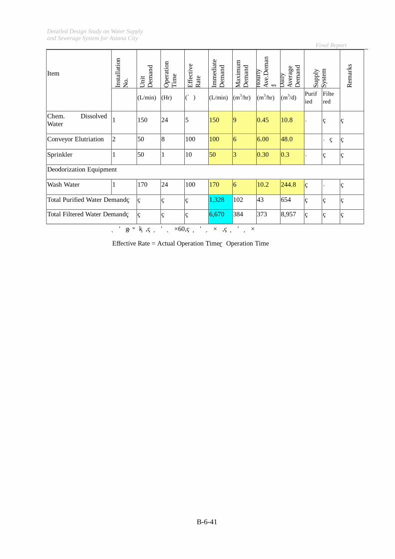
Chem. Dissolved Water 1 150 24 5 150 9 0.45 10.8 ○
Conveyor Elutriation 2 50 8 100 100 6 6.00 48.0 ○
Sprinkler 1 50 1 10 50 3 0.30 0.3 ○
Deodorization Equipment
Wash Water 1 170 24 100 170 6 10.2 244.8 ○
Total Purified Water Demand 1,328 102 43 654
Total Filtered Water Demand 6,670 384 373 8,957
A=①×②, B=A×60, C=B×�, D=C×�
Effective Rate = Actual Operation Time/Operation Time

Detailed Design Study on Water Supply and Sewerage System for Astana City Final Report
B-6-42
13. Hopper House
13.1 Cake Hopper
(1) Design Conditions
Type: Motor Driven cut Gate
Sludge Cake Volume: 74.0 m3/day
Storage Time: 0.5 day
Hopper Capacity: 15m3
Voidage of sludge cake in loose condition: 30 percent
Sludge density: (100-30)/100=0.7
(2) Quantity
74.0m3/day × 0.5 × 1/0.7 × 1/15
=3.524 → 4 units for duty 2 dewatering units considering allowance for holiday
(3) Specifications
Type: Motor Driven cut Gate
Hopper Capacity: 15m3
Power Requirement: 2.2 kW×2
Quantity: 4 (2 standby)
14. Boiler House
14.1 Boiler
(1) Design Conditions
Total Thermal Volume: q0=1,510,000kcal/hr (From the thermal calculation of digester)
(2) Amount of Evaporation
Actual Amount of Evaporation: W = q0÷I2-I3 (kg/hr)
I2: Enthalpy of Generated Vapor in Common Pressure 649.5kcal/kg
I3: Enthalpy of Digested Sludge 35kcal/kg
W=1,510,000÷(649.5-35)=2,457 kg/hr
Relative Amount of Evaporation:
I0: Evaporation Heat for Water at 100 degree: 538.8 kcal/kg
I1: Enthalpy of Boiler at the entrance: 5 kcal/kg
W0=2,457*(649.5-5)/538.8=2,939 kg/hr
(3) Specifications of Boiler
Quantity: 2
W=2,939 kg/hr + heating = 4,000 kg/hr
Actual Amount of Evaporation Coal boiler 4,000 kg/hr × 2
Gas boiler 2,000 kg/hr × 1

Detailed Design Study of Water Supply and Sewerage System in Astana City Final Report
Required Capacity of Water Tube Coal Boiler for Digester (1/4)
symbol
configuration
D1 = 3.4 m D1 = 3.4 mD2 = 17 m D2 = 17 mD3 = 17 m D3 = 17 mD4 = 1 m D4 = 1 mH1 = 1.2 m H1 = 1.2 mH2 = 2.35 m H2 = 2.35 mH3 = 0 m H3 = 0 mH4 = 0 m H4 = 0 mH5 = 8 m H5 = 8 mH6 = 2.1 m H6 = 2.1 m
q 548 m3/d 548 m3/dDry solid ( 27.4 DS-t/d ( 27.4 DS-t/d
Water content 95 %) 95 %)
Q1 1 124 24
= 1,096,000 kcal/hr = 1,096,000 kcal/hr
C 1 kcal/l・℃ 1 kcal/l・℃
TD 53 degree 53 degree
B-6-43
C × q × (TD - TS) × 103×C × q × (TD - TS) × 103×Required Heat Energy
Specific heat value of sludge
t= -35 degree(minimum temp)
Water tube coal boiler
Item
Model
Digester
Sludge flow rate
t= -16.1 degree(average temp)
Water tube coal boiler
������������������
������������������
������������������
������������������
φD3
φD4
φD2
φD1
GL
H2H1
H3
H4
H5
H6

Detailed Design Study of Water Supply and Sewerage System in Astana City Final Report
Required Capacity of Water Tube Coal Boiler for Digester (2/4)
symbol
Sludge Temp. TS 5 degree( winter) 5 degree( winter)in winter
Q2
= 60,809 kcal/hr/tank = 58,013 kcal/hr/tank
Steel Top cover K1 5.17 kcal/m2/hr/degree 5.17 kcal/m2/hr/degree
Gas reservoir K2 0.345 kcal/m2/hr/degree 0.345 kcal/m2/hr/degreeunder the ceiling con 250mm, mortar 30mm, perlite 100mm
Sludge reservoir K3 0 kcal/m2/hr/degree 0 kcal/m2/hr/degreeunder the ceiling
Side wall K4 0 kcal/m2/hr/degree 0 kcal/m2/hr/degreeon the GL
K5 0 kcal/m2/hr/degree 0 kcal/m2/hr/degree
Side wall K6 1.089777 kcal/m2/hr/degree 1.089777 kcal/m2/hr/degreeunder the GL
Bottom slab K7 1.784197 kcal/m2/hr/degree 1.784197 kcal/m2/hr/degree
Steel Top cover A1 3.1416 3.14164 4
= 9.1 m2 = 9.1 m2
Gas reservoir A2
under the ceiling= 221.2678 m2 = 221.2678 m2
B-6-44
Heat retention Sidewall
Area
t= -16.1 degree(average temp)
Heat Radiation of a Digester
× D12
Heat flow rate
Item t= -35 degree(minimum temp)
{(K1 × A1 + K2 × A2 + K3 × A3 + K4 ×A4 + K 5× A5) × (TD-TA)+ K6 × A6 ×(TD-TB1)+K7×A7×(TD-TB2)}×1.2
× D12
π× H12 +
D2
2-
D1
2
2
×D2
2+
D1
2π× H1
2 +D2
2-
D1
2
2
×D2
2+
D1
2
Detailed Design Study of Water Supply and Sewerage System in Astana City Final Report
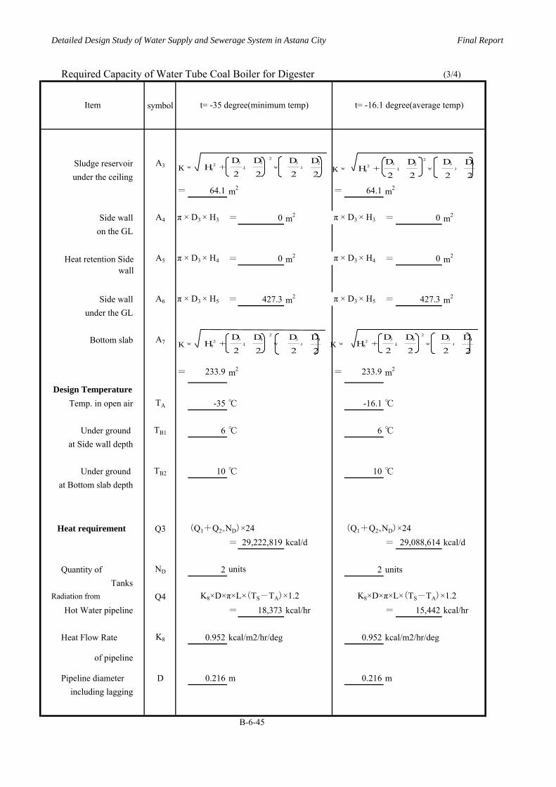
Required Capacity of Water Tube Coal Boiler for Digester (3/4)
symbol
Sludge reservoir A3
under the ceiling= 64.1 m2 = 64.1 m2
Side wall A4 π × D3 × H3 = 0 m2 π × D3 × H3 = 0 m2
on the GL
A5 π × D3 × H4 = 0 m2 π × D3 × H4 = 0 m2
Side wall A6 π × D3 × H5 = 427.3 m2 π × D3 × H5 = 427.3 m2
under the GL
Bottom slab A7
= 233.9 m2 = 233.9 m2
Temp. in open air TA -35 ℃ -16.1 ℃
Under ground TB1 6 ℃ 6 ℃at Side wall depth
Under ground TB2 10 ℃ 10 ℃at Bottom slab depth
Q3 (Q1+Q2×ND)×24 (Q1+Q2×ND)×24= 29,222,819 kcal/d = 29,088,614 kcal/d
Quantity of ND 2 2 unitsTanks
Q4Hot Water pipeline = 18,373 kcal/hr = 15,442 kcal/hr
Heat Flow Rate K8 0.952 kcal/m2/hr/deg 0.952 kcal/m2/hr/deg
of pipeline
Pipeline diameter D 0.216 m 0.216 mincluding lagging
B-6-45
t= -35 degree(minimum temp)
Heat retention Sidewall
Design Temperature
Heat requirement
K8×D×π×L×(TS-TA)×1.2Radiation from
Item
K8×D×π×L×(TS-TA)×1.2
units
t= -16.1 degree(average temp)
π× H12 +
D3
2-
D2
2
2
×D3
2+
D2
2
π× H52 +
D3
2-
D4
2
2
×D3
2+
D4
2
π× H12 +
D3
2-
D2
2
2
×D3
2+
D2
2
π× H52 +
D3
2-
D4
2
2
×D3
2+
D4
2

Detailed Design Study of Water Supply and Sewerage System in Astana City Final Report
Required Capacity of Water Tube Coal Boiler for Digester (4/4)
symbol
Pipeline length L 200 m 200 m
Temp. of Water TS 83.5 ℃ 83.5 ℃
Open air Temp. TA -35 ℃ -16.1 ℃
N 2 units 2 units
qN
Q1 + Q2 Q1 + Q2
= 29,241,191 kcal/d = 29,104,057 kcal/d→→→→ 29,240,000 kcal/d →→→→ 29,100,000 kcal/d
Operation time t 24 hr/d 24 hr/d
Rating output q qN/(t ×ηB×ηE) qN/(t ×ηB×ηE)
= 1,508,772 kcal/hr = 1,501,548 kcal/hr= 1,510,000 kcal/hr = 1,500,000 kcal/hr
Efficiency of boiler ηB 0.85 0.85
ηE 0.95 0.95
B-6-46
Required heat capacity
Efficiency of Heatexchanger
Quantity
Item t= -35 degree(minimum temp)
Inlet 72deg, Outlet 95deg, Average83.5deg Inlet 72deg, Outlet 95deg, Average83.5deg
t= -16.1 degree(average temp)
Q3
t+Q4 ×
I-I'
1×
I-I1
l

Detailed Design Study on Water Supply and Sewerage System for Astana City Final Report
B-6-47
13. Intermediate Pump Stations
13.1. PS No.1 13.1.1 Fine Screen
The principal role of screening is to remove coarse materials from the flow streams.
(1) Design Conditions
① Automatic Cleaning Bar Screening
② Design Maximum Hourly Flow: 1,600 m3/hr (2) Scale of Chamber
0.6m(Width)×0.6m(Depth)
(3) Specifications
Type: Mechanically Cleaning Bar Screen
Power Requirement: 1.5 kW
Installation Number: 1
13.1.2 Sewage Pumps
The principal role of pumps is to rise up and transfer wastewater from sewer to treatment process.
(1) Design Conditions
① Horizontal Shaft Volute Type Mixed Flow Pump
② Design Maximum Hourly Flow: 1,600 m3/hr (26.7m3/min) (2) Capacities of Pumps
14m3/min
Total Capacity: 14×2=28 m3/min
( 26.7 m3/min < 28 m3/min ・・・ OK)
(3) Total Pump Head
① Actual Pump Head H1 6.2m
② Head Loss in Pipe H2 2.949m
③ Total Head H3
H3 = H1 + H2 = 6.2 + 2.949 = 9.149 m → 10 m (Refer to B-6-74 to 76, hereinafter )
(4) Electric Motor Power
D= α)(1γ
rHQ0.163 ××××
= (1+0.15)0.70
110140.163 ×××
= 37.49 → 45kW

Detailed Design Study on Water Supply and Sewerage System for Astana City Final Report
B-6-48
(5) Specifications
Type: Horizontal Shaft Volute Type Mixed Flow Pump
Discharge Capacity: 14 m3/min
Total Head: 10 m
Power Requirement: 45 kW
Installation Number: 2 (2 Standby)
13.1.3 Sump Drainage Pumps
Floor Drain Pumps settled in drain pits drain miscellaneous used wastewater.
(1) Design Conditions
① Removal Submersible Pump
② Installation Number: 2 (2) Capacities of Pumps
0.3 m3/min
(3) Total Pump Head
15 m
(4) Specifications
Type: Removal Submersible Pump
Discharge Capacity: 0.3 m3/min
Total Head: 15 m
Power Requirement: 1.5 kW
Installation Number: 2
13.1.4 Exhaust Fan
Exhaust fan ventilates the screen chamber.
(1) Ventilation Capacity
(π × 162/4) ×1/2 × 10 mH × 3 times/hr × 1/60 = 50.24 m3/min (2) Specifications
Type: Centrifugal Fan
Air Flow Capacity: 55 m3/min
Power Requirement: 3.7 kW
Installation Number: 1
13.1.5 Air Intake Fan
Air Intake Fan (1) intakes air in the underground screen chamber.
(1) Ventilation Capacity
(π × 162/4) × 10 mH × 3 times/hr × 1/60 = 100.48 m3/min
(2) Specifications
Type: Centrifugal Fan

Detailed Design Study on Water Supply and Sewerage System for Astana City Final Report
B-6-49
Air Flow Capacity: 105 m3/min
Power Requirement: 5.5 kW
Installation Number: 1
13.2. PS No.2
13.2.1 Sewage Pumps
The principal role of pumps is to rise up and transfer wastewater from sewer to treatment
process.
(1) Design Conditions
① Horizontal Shaft Volute Type Mixed Flow Pump
② Design Maximum Hourly Flow: 900 m3/hr (15m3/min) (2) Capacities of Pumps
7.5m3/min
Total Capacity: 7.5×2=15 m3/min
( 15 m3/min < 15 m3/min ・・・ OK)
(3) Total Pump Head
Actual Pump Head H1
4.57m
Head Loss in Pipe H2
2.075m
Total Head H3
H3 = H1 + H2 = 4.57 + 2.075 = 6.645 m → 7 m
(4) Electric Motor Power
D= α)(1γ
rHQ0.163 ××××
= (1+0.15)0.52
177.50.163 ×××
= 18.93 → 22kW
(5) Specifications
Type: Horizontal Shaft Volute Type Mixed Flow Pump
Discharge Capacity: 7.5 m3/min
Total Head: 7 m
Power Requirement: 22 kW
Installation Number: 2 (1 Standby)
13.2.2 Sump Drainage Pumps
Floor Drain Pumps settled in drain pits drain miscellaneous used wastewater.

Detailed Design Study on Water Supply and Sewerage System for Astana City Final Report
B-6-50
(1) Design Conditions
① Removal Submersible Pump
② Installation Number: 1 (2) Capacities of Pumps
0.3 m3/min
(3) Total Pump Head
15 m
(4) Specifications
Type: Removal Submersible Pump
Discharge Capacity: 0.3 m3/min
Total Head: 15 m
Power Requirement: 1.5 kW
Installation Number:1
13.2.3 Exhaust Fan
Exhaust fan ventilates the screen chamber.
(1) Ventilation Capacity
(π × 92/4) ×1/2 × 4 mH × 3 times/hr × 1/60 = 6.36 m3/min
(2) Specifications
Type: Centrifugal Fan
Air Flow Capacity: 8 m3/min
Power Requirement: 0.4 kW
Installation Number: 1
13.2.4 Air Intake Fan
Air Intake Fan intakes air in the underground screen chamber.
(1) Ventilation Capacity
(π × 92/4) × 7 mH × 3 times/hr × 1/60 = 11.13 m3/min
(2) Specifications
Type: Centrifugal Fan
Air Flow Capacity: 14 m3/min
Power Requirement: 0.75 kW
Installation Number: 1
13.3. PS No.3 13.3.1 Fine Screen
The principal role of screening is to remove coarse materials from the flow streams.

Detailed Design Study on Water Supply and Sewerage System for Astana City Final Report
B-6-51
(1) Design Conditions
③ Automatic Cleaning Bar Screening
④ Design Maximum Hourly Flow: 2,400 m3/hr (2) Scale of Chamber
0.6m(Width)×0.6m(Depth)
(3) Specifications
Type: Mechanically Cleaning Bar Screen
Power Requirement: 1.5 kW
Installation Number: 2
13.3.2 Sewage Pumps
The principal role of pumps is to rise up and transfer wastewater from sewer to treatment process.
(1) Design Conditions
⑤ Horizontal Shaft Volute Type Mixed Flow Pump
⑥ Design Maximum Hourly Flow: 2,400 m3/hr (40m3/min) (2) Capacities of Pumps
14m3/min
Total Capacity: 14×3=42 m3/min
( 40 m3/min < 42 m3/min ・・・ OK)
(3) Total Pump Head
Actual Pump Head H1
4.52m
Head Loss in Pipe H2
4.22m
Total Head H3
H3 = H1 + H2 = 4.52 + 4.22 = 8.74 m → 9 m
(4) Electric Motor Power
D= α)(1γ
rHQ0.163 ××××
= (1+0.15)0.72
19140.163 ×××
= 32.8 → 37kW
(5) Specifications
Type: Horizontal Shaft Volute Type Mixed Flow Pump
Discharge Capacity: 14 m3/min
Total Head: 9 m
Power Requirement: 37 kW
Installation Number: 3 (2 Standby)

Detailed Design Study on Water Supply and Sewerage System for Astana City Final Report
B-6-52
13.3.3 Sump Drainage Pumps
Floor Drain Pumps settled in drain pits drain miscellaneous used wastewater.
(1) Design Conditions
⑦ Removal Submersible Pump
⑧ Installation Number: 1 (2) Capacities of Pumps
0.3 m3/min
(3) Total Pump Head
15 m
(4) Specifications
Type: Removal Submersible Pump
Discharge Capacity: 0.3 m3/min
Total Head: 15 m
Power Requirement: 1.5 kW
Installation Number: 1
13.3.4 Exhaust Fan
Exhaust fan ventilates the screen chamber.
(1) Ventilation Capacity
(π × 162/4) ×1/2 × 10 mH × 3 times/hr × 1/60 = 50.24 m3/min
(2) Specifications
Type: Centrifugal Fan
Air Flow Capacity: 55 m3/min
Power Requirement: 3.7 kW
Installation Number: 1
13.3.5 Air Intake Fan
Air Intake Fan (1) intakes air in the underground screen chamber.
(1) Ventilation Capacity
(π × 162/4) × 10 mH × 3 times/hr × 1/60 = 100.48 m3/min
(2) Specifications
Type: Centrifugal Fan
Air Flow Capacity: 105 m3/min
Power Requirement: 5.5 kW
Installation Number: 1

Detailed Design Study on Water Supply and Sewerage System for Astana City Final Report
B-6-53
13.4. PS No.4 13.4.1 Fine Screen
The principal role of screening is to remove coarse materials from the flow streams.
(1) Design Conditions
① Automatic Cleaning Bar Screening
② Design Maximum Hourly Flow: 900 m3/hr
(2) Scale of Chamber
1.2m(Width)×1.2m(Depth)
(3) Specifications
Type: Mechanically Cleaning Bar Screen
Power Requirement: 1.5 kW
Installation Number: 1
13.4.2 Sewage Pumps
The principal role of pumps is to rise up and transfer wastewater from sewer to treatment process.
(1) Design Conditions
① Horizontal Shaft Volute Type Mixed Flow Pump
② Design Maximum Hourly Flow: 900 m3/hr (15m3/min) (2) Capacities of Pumps
7.5m3/min
Total Capacity: 7.5 =15 m3/min
( 15 m3/min < 15 m3/min ・・・ OK)
(3) Total Pump Head
① Actual Pump Head H1 4.15m
② Head Loss in Pipe H2 2.336m
③ Total Head H3
H3 = H1 + H2 = 4.15 + 2.336 = 6.486 m → 7 m
(4) Electric Motor Power
D= α)(1γ
rHQ0.163 ××××
= (1+0.15)0.52
177.50.163 ×××
= 18.93 → 22kW
(5) Specifications
Type: Horizontal Shaft Volute Type Mixed Flow Pump
Discharge Capacity: 7.5 m3/min

Detailed Design Study on Water Supply and Sewerage System for Astana City Final Report
B-6-54
Total Head: 7 m
Power Requirement: 22 kW
Installation Number: 2 (1 Standby)
13.4.3 Sump Drainage Pumps
Floor Drain Pumps settled in drain pits drain miscellaneous used wastewater.
(1) Design Conditions
① Removal Submersible Pump
② Installation Number: 2 (2) Capacities of Pumps
0.3 m3/min
(3) Total Pump Head
15 m
(4) Specifications
Type: Removal Submersible Pump
Discharge Capacity: 0.3 m3/min
Total Head: 15 m
Power Requirement: 1.5 kW
Installation Number: 2
13.4.4 Exhaust Fan
Exhaust fan ventilates the screen chamber.
(1) Ventilation Capacity
(π × 122/4) ×1/2 × 4 mH × 3 times/hr × 1/60 = 11.3 m3/min
(2) Specifications
Type: Centrifugal Fan
Air Flow Capacity: 13 m3/min
Power Requirement: 0.75 kW
Installation Number: 1
13.4.5 Air Intake Fan
Air Intake Fan (1) intakes air in the underground screen chamber.
(1) Ventilation Capacity
(π × 122/4) ×1/2× 7 mH × 3 times/hr × 1/60 = 19.8 m3/min
(2) Specifications
Type: Centrifugal Fan
Air Flow Capacity: 22 m3/min
Power Requirement: 1.5 kW
Installation Number: 1

Detailed Design Study on Water Supply and Sewerage System for Astana City Final Report
B-6-55
13.5. PS No.6 13.5.1 Sewage Pumps
The principal role of pumps is to rise up and transfer wastewater from sewer to treatment
process.
(1) Design Conditions
① Horizontal Shaft Volute Type Mixed Flow Pump
② Design Maximum Hourly Flow: 3,200 m3/hr (53.33m3/min) (2) Capacities of Pumps
27m3/min
Total Capacity: 27×2=54 m3/min
( 53.33 m3/min < 54 m3/min ・・・ OK)
(3) Total Pump Head
① Actual Pump Head H1 3.977m
② Head Loss in Pipe H2 5.977m
③ Total Head H3
H3 = H1 + H2 = 3.977 + 5.977 = 9.954 m → 10 m
(4) Electric Motor Power
D= α)(1γ
rHQ0.163 ××××
= (1+0.15)0.74
110270.163 ×××
= 68.39 → 75kW
(5) Specifications
Type: Horizontal Shaft Volute Type Mixed Flow Pump
Discharge Capacity: 27 m3/min
Total Head: 10 m
Power Requirement: 75 kW
Installation Number: 2 (2 Standby)
13.5.2 Sump Drainage Pumps
Floor Drain Pumps settled in drain pits drain miscellaneous used wastewater.
(1) Design Conditions
① Removal Submersible Pump
② Installation Number: 2
Detailed Design Study on Water Supply and Sewerage System for Astana City Final Report
B-6-56
(2) Capacities of Pumps
0.3 m3/min
(3) Total Pump Head
15 m
(4) Specifications
Type: Removal Submersible Pump
Discharge Capacity: 0.3 m3/min
Total Head: 15 m
Power Requirement: 1.5 kW
Installation Number:2
13.5.3 Exhaust Fan
Exhaust fan ventilates the screen chamber.
(1) Ventilation Capacity
(π × 122/4) ×1/2 × 4 mH × 3 times/hr × 1/60 = 11.3 m3/min
(2) Specifications
Type: Centrifugal Fan
Air Flow Capacity: 13 m3/min
Power Requirement: 0.75 kW
Installation Number: 1
13.5.4 Air Intake Fan
Air Intake Fan intakes air in the underground screen chamber.
(1) Ventilation Capacity
(π × 122/4) × 7 mH × 3 times/hr × 1/60 = 19.8 m3/min
(2) Specifications
Type: Centrifugal Fan
Air Flow Capacity: 22 m3/min
Power Requirement: 1.5 kW
Installation Number: 1
13.6. PS No.7
13.6.1 Fine Screen
The principal role of screening is to remove coarse materials from the flow streams.
(1) Design Conditions
① Automatic Cleaning Bar Screening
Detailed Design Study on Water Supply and Sewerage System for Astana City Final Report
B-6-57
② Design Maximum Hourly Flow: 5,700 m3/hr
(2) Scale of Chamber
1.0m(Width)×1.0m(Depth)
(3) Specifications
Type: Mechanically Cleaning Bar Screen
Power Requirement: 1.5 kW
Installation Number: 2
13.6.2 Sewage Pumps
The principal role of pumps is to rise up and transfer wastewater from sewer to treatment process.
(1) Design Conditions
① Vertical Shaft Type Mixed Flow Pump
② Horizontal Shaft Volute Type Mixed Flow Pump
③ Design Maximum Hourly Flow: 5,700 m3/hr (95m3/min)
(2) Capacities of Pumps
27m3/min× 2 (1 standby)
14m3/min× 2
7.5m3/min× 2
Total Capacity: 27×2 + 14×2+7.5×2 = 97 m3/min
( 95 m3/min < 97 m3/min ・・・ OK)
(3) Total Pump Head
① Actual Pump Head H1 5.69m
② Head Loss in Pipe H2 4.892m
③ Total Head H3
H3 = H1 + H2 = 5.69 + 4.892 = 10.582 m → 11 m (4) Electric Motor Power
D= α)(1γ
rHQ0.163 ××××
= (1+0.15)0.77
1270.163 ××× 11
= 72.3 → 75kW
= (1+0.15)0.72
1140.163 ××× 11
= 40.1 → 45kW
= (1+0.15)0.52
17.50.163 ××× 11

Detailed Design Study on Water Supply and Sewerage System for Astana City Final Report
B-6-58
= 29.74 → 30kW
③ Specifications Type: Vertical Shaft Type Mixed Flow Pump
Type: Horizontal Shaft Volute Type Mixed Flow Pump
Discharge Capacity: 27 m3/min
14 m3/min
7.5 m3/min
Total Head: 11 m
Power Requirement: 75kw
45kw
30 kW
Installation Number: 2 (1 Standby)
2
2
13.6.3 Sump Drainage Pumps
Floor Drain Pumps settled in drain pits drain miscellaneous used wastewater.
(1) Design Conditions
① Removal Submersible Pump
② Installation Number: 2 (2) Capacities of Pumps
0.3 m3/min
(3) Total Pump Head
15 m
(4) Specifications
Type: Removal Submersible Pump
Discharge Capacity: 0.3 m3/min
Total Head: 15 m
Power Requirement: 1.5 kW
Installation Number: 2
13.6.4 Exhaust Fan
Exhaust fan ventilates the screen chamber.
(1) Ventilation Capacity
(π × 242/4) × 5 mH ÷ 2 × 3 times/hr × 1/60 = 56.52 m3/min
(2) Specifications
Type: Sirocco Fan
Air Flow Capacity: 60 m3/min
Pressure: 15 mmAq

Detailed Design Study on Water Supply and Sewerage System for Astana City Final Report
B-6-59
Power Requirement: 0.75 kW
Installation Number: 1
13.6.5 Air Intake Fan (1)
Air Intake Fan (1) intakes air in the underground screen chamber.
(1) Ventilation Capacity
(π × 242/4) × 5 mH ÷ 2 × 3 times/hr × 1/60 = 56.52 m3/min
(2) Specifications
Type: Sirocco Fan
Air Flow Capacity: 60 m3/min
Pressure: 15 mmAq
Power Requirement: 0.75 kW
Installation Number: 1
13.6.6 Air Intake Fan (2)
Air Intake Fan (2) intakes air in the motor room.
(1) Ventilation Capacity
Heat yielded by motors should be considered.
18 × 24 × 12 mH × 3 times/hr × 1/60 = 259.2 m3/min
(2) Specifications
Type: Turbo Fan
Air Flow Capacity: 260 m3/min
Pressure: 15 mmAq
Power Requirement: 3.7 kW
Installation Number: 1
13.6.7 Air Intake Fan (3)
Air Intake Fan (3) intakes air in the underground pump room.
(1) Ventilation Capacity
(π × 242/4) × 5 mH ÷ 2 × 3 times/hr × 1/60 = 56.52 m3/min
(2) Specifications
Type: Sirocco Fan
Air Flow Capacity: 60 m3/min
Pressure: 15 mmAq
Power Requirement: 0.75 kW
Installation Number: 1

Detailed Design Study on Water Supply and Sewerage System for Astana City Final Report
B-6-60
13.7. PS No.10 13.7.1 Fine Screen
The principal role of screening is to remove coarse materials from the flow streams.
(1) Design Conditions
① Automatic Cleaning Bar Screening
② Design Maximum Hourly Flow: 1,350 m3/hr (2) Scale of Chamber
0.8m(Width)×0.8m(Depth)
(3) Specifications
Type: Mechanically Cleaning Bar Screen
Power Requirement: 1.5 kW
Installation Number: 1
13.7.2 Sewage Pumps
The principal role of pumps is to rise up and transfer wastewater from sewer to treatment process.
(1) Design Conditions
① Horizontal Shaft Volute Type Mixed Flow Pump
② Design Maximum Hourly Flow: 1,350 m3/hr (22.5m3/min) (2) Capacities of Pumps
7.5m3/min
Total Capacity: 7.5×3=22.5 m3/min
( 22.5 m3/min < 22.5 m3/min ・・・ OK)
(3) Total Pump Head
Actual Pump Head H1
4.93m
Head Loss in Pipe H2
5.852m
Total Head H3
H3 = H1 + H2 = 4.93 + 5.852 = 10.782 m → 11 m
(4) Electric Motor Power
D= α)(1γ
rHQ0.163 ××××
= (1+0.15)0.52
1117.50.163 ×××
= 29.74 → 30kW
(5) Specifications
Type: Horizontal Shaft Volute Type Mixed Flow Pump
Discharge Capacity: 7.5 m3/min

Detailed Design Study on Water Supply and Sewerage System for Astana City Final Report
B-6-61
Total Head: 11 m
Power Requirement: 30 kW
Installation Number: 3 (2 Standby)
13.7.3 Sump Drainage Pumps
Floor Drain Pumps settled in drain pits drain miscellaneous used wastewater.
(1) Design Conditions
① Removal Submersible Pump
② Installation Number: 2 (2) Capacities of Pumps
0.3 m3/min
(3) Total Pump Head
15 m
(4) Specifications
Type: Removal Submersible Pump
Discharge Capacity: 0.3 m3/min
Total Head: 15 m
Power Requirement: 1.5 kW
Installation Number: 2
13.7.4 Exhaust Fan
Exhaust fan ventilates the screen chamber.
(1) Ventilation Capacity
(π × 162/4) ×1/2 × 10 mH × 3 times/hr × 1/60 = 50.24 m3/min
(2) Specifications
Type: Centrifugal Fan
Air Flow Capacity: 55 m3/min
Power Requirement: 3.7 kW
Installation Number: 1
13.7.5 Air Intake Fan
Air Intake Fan (1) intakes air in the underground screen chamber.
(1) Ventilation Capacity
(π × 162/4) × 10 mH × 3 times/hr × 1/60 = 100.48 m3/min
(2) Specifications
Type: Centrifugal Fan
Air Flow Capacity: 105 m3/min
Power Requirement: 5.5 kW
Installation Number: 1

Detailed Design Study on Water Supply and Sewerage System for Astana City Final Report
B-6-62
13.8. PS No.11 13.8.1 Sewage Pumps
The principal role of pumps is to rise up and transfer wastewater from sewer to treatment
process.
(1) Design Conditions
① Horizontal Shaft Volute Type Mixed Flow Pump
② Design Maximum Hourly Flow: 228 m3/hr (3.8m3/min) (2) Capacities of Pumps
1.9m3/min
Total Capacity: 1.9×2=3.8 m3/min
( 3.8 m3/min < 3.8 m3/min ・・・ OK)
(3) Total Pump Head
Actual Pump Head H1
3.97m
Head Loss in Pipe H2
3.822m
Total Head H3
H3 = H1 + H2 = 3.97 + 3.822 = 7.792 m → 8 m
(4) Electric Motor Power
D= α)(1γ
rHQ0.163 ××××
= (1+0.15)0.35
181.90.163 ×××
= 8.14 → 11kW
(5) Specifications
Type: Horizontal Shaft Volute Type Mixed Flow Pump
Discharge Capacity: 1.9 m3/min
Total Head: 8 m
Power Requirement: 11 kW
Installation Number: 2 (1 Standby)
13.8.2 Exhaust Fan
Exhaust fan ventilates the screen chamber.
(1) Ventilation Capacity
(π × 62/4) ×1/2 × 4 mH × 3 times/hr × 1/60 = 2.83 m3/min
(2) Specifications
Type: Centrifugal Fan

Detailed Design Study on Water Supply and Sewerage System for Astana City Final Report
B-6-63
Air Flow Capacity: 4 m3/min
Power Requirement: 0.4 kW
Installation Number: 1
13.8.3 Air Intake Fan
Air Intake Fan intakes air in the underground screen chamber.
(1) Ventilation Capacity
(π × 62/4) ×1/2 × 7 mH × 3 times/hr × 1/60 = 4.95 m3/min
(2) Specifications
Type: Centrifugal Fan
Air Flow Capacity: 6 m3/min
Power Requirement: 0.4 kW
Installation Number: 1
13.9. PS No.15 13.9.1 Sewage Pumps
The principal role of pumps is to rise up and transfer wastewater from sewer to treatment
process.
(1) Design Conditions
① Horizontal Shaft Volute Type Mixed Flow Pump
② Design Maximum Hourly Flow: 500 m3/hr (8.33m3/min)
(2) Capacities of Pumps
4.2m3/min
Total Capacity: 4.2×2=8.4 m3/min
( 8.33 m3/min < 8.4 m3/min ・・・ OK)
(3) Total Pump Head
Actual Pump Head H1
4.00m
Head Loss in Pipe H2
6.427m
Total Head H3
H3 = H1 + H2 = 4.00 + 6.427 = 10.427 m → 11 m
(4) Electric Motor Power
D= α)(1γ
rHQ0.163 ××××
= (1+0.15)0.52
1114.20.163 ×××

Detailed Design Study on Water Supply and Sewerage System for Astana City Final Report
B-6-64
= 16.65 → 18.5kW
(5) Specifications
Type: Horizontal Shaft Volute Type Mixed Flow Pump
Discharge Capacity: 4.2 m3/min
Total Head: 11 m
Power Requirement: 18.5 kW
Installation Number: 2 (1 Standby)
9.2 Exhaust Fan
Exhaust fan ventilates the screen chamber.
(1) Ventilation Capacity
(π × 62/4) ×1/2 × 4 mH × 3 times/hr × 1/60 = 2.83 m3/min
(2) Specifications
Type: Centrifugal Fan
Air Flow Capacity: 4 m3/min
Power Requirement: 0.4 kW
Installation Number: 1
13.9.3 Air Intake Fan
Air Intake Fan intakes air in the underground screen chamber.
(1) Ventilation Capacity
(π × 62/4) ×1/2 × 7 mH × 3 times/hr × 1/60 = 4.95 m3/min
(2) Specifications
Type: Centrifugal Fan
Air Flow Capacity: 6 m3/min
Power Requirement: 0.4 kW
Installation Number: 1
13.10. PS No.16
13.10.1 Sewage Pumps
The principal role of pumps is to rise up and transfer wastewater from sewer to treatment
process.
(1) Design Conditions
① Horizontal Shaft Volute Type Mixed Flow Pump
② Design Maximum Hourly Flow: 160 m3/hr (2.67m3/min) (2) Capacities of Pumps
1.4m3/min
Total Capacity: 1.4×2=2.8 m3/min

Detailed Design Study on Water Supply and Sewerage System for Astana City Final Report
B-6-65
( 2.67 m3/min < 2.8 m3/min ・・・ OK)
(3) Total Pump Head
Actual Pump Head H1
5.3m
Head Loss in Pipe H2
18.141m
Total Head H3
H3 = H1 + H2 = 5.3 + 18.141 = 23.441 m → 24 m
(4) Electric Motor Power
D= α)(1γ
rHQ0.163 ××××
= (1+0.15)0.52
1241.40.163 ×××
= 12.1 → 15kW
(5) Specifications
Type: Horizontal Shaft Volute Type Mixed Flow Pump
Discharge Capacity: 1.4 m3/min
Total Head: 24 m
Power Requirement: 15 kW
Installation Number: 2 (1 Standby)
13.10.2 Exhaust Fan
Exhaust fan ventilates the screen chamber.
(1) Ventilation Capacity
(π × 62/4) ×1/2 × 4 mH × 3 times/hr × 1/60 = 2.83 m3/min
(2) Specifications
Type: Centrifugal Fan
Air Flow Capacity: 4 m3/min
Power Requirement: 0.4 kW
Installation Number: 1
13.10.3 Air Intake Fan
Air Intake Fan intakes air in the underground screen chamber.
(1) Ventilation Capacity
(π × 62/4) ×1/2 × 7 mH × 3 times/hr × 1/60 = 4.95 m3/min
(2) Specifications
Type: Centrifugal Fan
Air Flow Capacity: 6 m3/min
Power Requirement: 0.4 kW

Detailed Design Study on Water Supply and Sewerage System for Astana City Final Report
B-6-66
Installation Number: 1
13.11. PS No.17
13.11.1 Sewage Pumps
The principal role of pumps is to rise up and transfer wastewater from sewer to treatment
process.
(1) Design Conditions
① Horizontal Shaft Volute Type Mixed Flow Pump
② Design Maximum Hourly Flow: 250 m3/hr (4.17m3/min)
(2) Capacities of Pumps
4.2m3/min
Total Capacity: 4.2×1=4.2 m3/min
( 4.17 m3/min < 4.2 m3/min ・・・ OK)
(3) Total Pump Head
Actual Pump Head H1
4.9m
Head Loss in Pipe H2
12.375m
Total Head H3
H3 = H1 + H2 = 4.9 + 12.375 = 17.275 m → 18 m
(4) Electric Motor Power
D= α)(1γ
rHQ0.163 ××××
= (1+0.15)0.52
14.20.163 ××× 18
= 27.3 → 30kW
(5) Specifications
Type: Horizontal Shaft Volute Type Mixed Flow Pump
Discharge Capacity: 4.2 m3/min
Total Head: 18 m
Power Requirement: 30 kW
Installation Number: 1 (1 Standby)
13.11.2 Exhaust Fan
Exhaust fan ventilates the screen chamber.
(1) Ventilation Capacity
(π × 32/4) ×1/2 × 4 mH × 3 times/hr × 1/60 = 0.7065 m3/min

Detailed Design Study on Water Supply and Sewerage System for Astana City Final Report
B-6-67
(2) Specifications
Type: Centrifugal Fan
Air Flow Capacity: 1 m3/min
Power Requirement: 0.2 kW
Installation Number: 1
13.11.3 Air Intake Fan
Air Intake Fan intakes air in the underground screen chamber.
(1) Ventilation Capacity
(π × 32/4) ×1/2 × 7 mH × 3 times/hr × 1/60 = 1.24 m3/min
(2) Specifications
Type: Centrifugal Fan
Air Flow Capacity: 1.5 m3/min
Power Requirement: 0.2 kW
Installation Number: 1
13.12. PS No.21 13.12.1 Sewage Pumps
The principal role of pumps is to rise up and transfer wastewater from sewer to treatment process.
(1) Design Conditions
① Horizontal Shaft Volute Type Mixed Flow Pump
② Design Maximum Hourly Flow: 200 m3/hr (3.33m3/min) (2) Capacities of Pumps
3.3m3/min
Total Capacity: 3.3×1=3.3 m3/min
( 3.3 m3/min < 3.3 m3/min ・・・ OK)
(3) Total Pump Head
Actual Pump Head H1
10.22m
Head Loss in Pipe H2
8.613m
Total Head H3
H3 = H1 + H2 = 10.22 + 8.613 = 18.833 m → 19 m
(4) Electric Motor Power
D= α)(1γ
rHQ0.163 ××××
= (1+0.15)0.50
1193.30.163 ×××

Detailed Design Study on Water Supply and Sewerage System for Astana City Final Report
B-6-68
= 23.5 → 30kW
(5) Specifications
Type: Horizontal Shaft Volute Type Mixed Flow Pump
Discharge Capacity: 3.3 m3/min
Total Head: 19 m
Power Requirement: 30 kW
Installation Number: 1 (1 Standby)
13.12.2 Sump Drainage Pumps
Floor Drain Pumps settled in drain pits drain miscellaneous used wastewater.
(1) Design Conditions
① Removal Submersible Pump
② Installation Number: 1 (2) Capacities of Pumps
0.3 m3/min
(3) Total Pump Head
15 m
(4) Specifications
Type: Removal Submersible Pump
Discharge Capacity: 0.3 m3/min
Total Head: 15 m
Power Requirement: 1.5 kW
Installation Number: 1
13.12.3 Exhaust Fan
Exhaust fan ventilates the screen chamber.
(1) Ventilation Capacity
(π × 62/4) ×1/2 × 4 mH × 3 times/hr × 1/60 = 2.83 m3/min (2) Specifications
Type: Centrifugal Fan
Air Flow Capacity: 4 m3/min
Power Requirement: 0.4 kW
Installation Number: 1
13.12.4 Air Intake Fan
Air Intake Fan intakes air in the underground screen chamber.
(1) Ventilation Capacity
(π × 62/4) ×1/2 × 7 mH × 3 times/hr × 1/60 = 4.95 m3/min
(2) Specifications
Type: Centrifugal Fan

Detailed Design Study on Water Supply and Sewerage System for Astana City Final Report
B-6-69
Air Flow Capacity: 6 m3/min
Power Requirement: 0.4 kW
Installation Number: 1
13.13. PS No.24
13.13.1 Sewage Pumps
The principal role of pumps is to rise up and transfer wastewater from sewer to treatment
process.
(1) Design Conditions
① Horizontal Shaft Volute Type Mixed Flow Pump
② Design Maximum Hourly Flow: 80 m3/hr (1.33m3/min) (2) Capacities of Pumps
1.3m3/min
Total Capacity: 1.3×1=1.3 m3/min
( 1.3 m3/min < 1.3 m3/min ・・・ OK)
(3) Total Pump Head
Actual Pump Head H1
6.54m
Head Loss in Pipe H2
8.25m
Total Head H3
H3 = H1 + H2 = 6.54 + 8.25 = 14.79 m → 15 m
(4) Electric Motor Power
D= α)(1γ
rHQ0.163 ××××
= (1+0.15)0.48
11.30.163 ××× 15
= 7.62 → 11kW
(5) Specifications
Type: Horizontal Shaft Volute Type Mixed Flow Pump
Discharge Capacity: 1.3 m3/min
Total Head: 15 m
Power Requirement: 11 kW
Installation Number: 1 (1 Standby)
13.13.2 Exhaust Fan
Exhaust fan ventilates the screen chamber.

Detailed Design Study on Water Supply and Sewerage System for Astana City Final Report
B-6-70
(1) Ventilation Capacity
(π × 42/4) ×1/2 × 5 mH × 3 times/hr × 1/60 = 1.57 m3/min (2) Specifications
Type: Centrifugal Fan
Air Flow Capacity: 2 m3/min
Power Requirement: 0.2 kW
Installation Number: 1
13.13.3 Air Intake Fan
Air Intake Fan intakes air in the underground screen chamber.
(1) Ventilation Capacity
(π × 42/4) ×1/2 × 8 mH × 3 times/hr × 1/60 = 2.51 m3/min
(2) Specifications
Type: Centrifugal Fan
Air Flow Capacity: 3 m3/min
Power Requirement: 0.2 kW
Installation Number: 1
13.14. PS No.28
13.14.1 Sewage Pumps
The principal role of pumps is to rise up and transfer wastewater from sewer to treatment
process.
(1) Design Conditions
① Submersible non-clog Type Vortex Flow Pump
② Design Maximum Hourly Flow: 80 m3/hr (1.3m3/min) (2) Capacities of Pumps
1.3m3/min
Total Capacity: 1.3×1=1.3 m3/min
( 1.3 m3/min < 1.3 m3/min ・・・ OK)
(3) Total Pump Head
Actual Pump Head H1
2.6m
Head Loss in Pipe H2
24.56m
Total Head H3
H3 = H1 + H2 = 2.6 + 24.56 = 27.16 m → 28 m

Detailed Design Study on Water Supply and Sewerage System for Astana City Final Report
B-6-71
(4) Electric Motor Power
D= α)(1γ
rHQ0.163 ××××
= (1+0.15)0.35
11.30.163 ××× 28
= 19.49 → 22kW
(5) Specifications
Type: Submersible non-clog Type Vortex Flow Pump
Discharge Capacity: 1.3 m3/min
Total Head: 28 m
Power Requirement: 22 kW
Installation Number: 1 (1 Standby)
13.15. PS No.34 13.15.1 Sewage Pumps
The principal role of pumps is to rise up and transfer wastewater from sewer to treatment
process.
(2) Design Conditions
① Submersible non-clog Type Vortex Flow Pump
② Design Maximum Hourly Flow: 50 m3/hr (0.833m3/min) (2) Capacities of Pumps
0.84m3/min
Total Capacity: 0.84×1=0.84 m3/min
( 0.833 m3/min < 0.84 m3/min ・・・ OK)
(3) Total Pump Head
Actual Pump Head H1
2.0m
Head Loss in Pipe H2
12.556m
Total Head H3
H3 = H1 + H2 = 2.0 + 12.556 = 14.556 m → 15 m
(4) Electric Motor Power
D= α)(1γ
rHQ0.163 ××××
= (1+0.15)0.35
10.840.163 ××× 15
= 6.74 → 7.5kW

Detailed Design Study on Water Supply and Sewerage System for Astana City Final Report
B-6-72
(5) Specifications
Type: Submersible non-clog Type Vortex Flow Pump
Discharge Capacity: 0.84 m3/min
Total Head: 15 m
Power Requirement: 7.5 kW
Installation Number: 1 (1 Standby)
13.16. PS No.37 13.16.1 Sewage Pumps
The principal role of pumps is to rise up and transfer wastewater from sewer to treatment
process.
(3) Design Conditions
① Submersible non-clog Type Vortex Flow Pump
② Design Maximum Hourly Flow: 50 m3/hr (0.833m3/min) (2) Capacities of Pumps
0.84m3/min
Total Capacity: 0.84×1=0.84 m3/min
( 0.833 m3/min < 0.84 m3/min ・・・ OK)
(3) Total Pump Head
Actual Pump Head H1
2.5m
Head Loss in Pipe H2
11.874m
Total Head H3
H3 = H1 + H2 = 2.5 + 11.874 + = m → 30 m
(4) Electric Motor Power
D= α)(1γ
rHQ0.163 ××××
= (1+0.15)0.30
10.840.163 ××× 30
= 15.74 → 18.5kW
(5) Specifications
Type: Submersible non-clog Type Vortex Flow Pump
Discharge Capacity: 0.84 m3/min
Total Head: 30 m
Power Requirement: 18.5 kW
Installation Number: 1 (1 Standby)
Detailed Design Study on Water Supply and Sewerage System for Astana City Final Report
B-6-73
13.17. PS No.IH
13.17.1 Sewage Pumps
The principal role of pumps is to rise up and transfer wastewater from sewer to treatment
process.
(1) Design Conditions
① Submersible non-clog Type Vortex Flow Pump
② Design Maximum Hourly Flow: 50 m3/hr (0.833m3/min) (2) Capacities of Pumps
0.84m3/min
Total Capacity: 0.84×1=0.84 m3/min
( 0.833 m3/min < 0.84 m3/min ・・・ OK)
(3) Total Pump Head
Actual Pump Head H1
4.18m
Head Loss in Pipe H2
10.203m
Total Head H3
H3 = H1 + H2 = 4.18 + 10.203 = 14.383 m → 15 m
(4) Electric Motor Power
D= α)(1γ
rHQ0.163 ××××
= (1+0.15)0.35
10.840.163 ××× 15
= 6.74 → 7.5 kW
(5) Specifications
Type: Submersible non-clog Type Vortex Flow Pump
Discharge Capacity: 0.84 m3/min
Total Head: 15 m
Power Requirement: 7.5 kW
Installation Number: 1 (1 Standby)

Table B-6-1 Elevation of pumping station, floors and etc.H0 H1 H2 H3 H4 H5 H6 MWL Head allowanc
m m
>2.5D or>0.75m
*2) m1 0.600 0.400 1.000 2.20 9.77 0.87 2.70 0.10 1.00
344.00 336.53 334.33 335.20 341.40 344.10 336.20 336.83 336.202 0.350 0.300 0.750 2.20 7.67 0.60 2.50 0.10 1.00
347.30 341.93 339.73 340.33 344.90 347.40 341.33 342.11 341.333 0.600 0.400 1.000 2.20 7.82 0.60 2.70 0.00 1.00
346.00 340.38 338.18 338.78 343.30 346.00 339.78 340.68 339.784 0.800 0.300 0.750 2.20 7.82 0.92 3.00 0.00 0.75
352.00 346.38 344.18 345.10 349.00 352.00 345.85 346.78 345.856 0.600 0.500 1.250 2.20 4.927 0.95 -0.25 0.50 1.25
343.80 341.57 339.37 340.32 344.55 344.30 341.57 341.87 341.577 1.000 0.700 1.750 3.50 10.58 1.07 5.07 0.20 1.75
347.00 340.12 336.62 337.69 342.13 347.20 339.44 340.62 339.4410 0.800 0.3 0.75 2.20 8.02 0.87 3.47 0.00 0.75
352.80 346.98 344.78 345.65 349.33 352.80 346.40 347.38 346.4011 0.300 0.15 0.75 1.80 6.47 0.3 2.45 -0.35 0.75
351.02 346.00 344.20 344.50 348.22 350.67 345.25 346.15 345.2515 0.300 0.25 0.75 1.80 6 0.3 2.45 -0.76 0.75
348.20 343.24 341.44 341.74 344.99 347.44 342.49 343.39 342.4916 0.250 0.15 0.75 1.80 7.27 0.47 1.75 0.30 0.75
351.40 346.23 344.43 344.90 349.95 351.70 345.65 346.36 345.6517 0.300 0.25 0.75 1.80 5.12 0.47 0 0.50 0.75
346.90 344.08 342.28 342.75 350.10 347.40 343.50 344.23 343.5021 0.200 0.2 0.75 1.80 6.44 0.47 -4.0 0.10 0.75
348.10 343.56 341.76 342.23 352.20 348.20 342.98 343.66 342.9824 0.200 0.15 0.75 1.80 6.89 0.60 0.00 0.10 0.75
349.80 344.81 343.01 343.61 349.90 349.90 344.36 344.91 344.36MH28 0.150 - - - 7.20 1.25 2.45 0.20 0.90360.35 355.50 353.35 354.6 357.9 360.55 355.50 - 355.50MH34 0.150 - - - 4.70 0.9 1 0.20 0.80345.30 342.50 340.8 341.7 344.3 345.50 342.50 - 342.50MH37 0.200 - - - 5.00 0.9 1.5 0.20 0.80346.70 343.60 341.9 342.8 345.2 346.90 343.60 - 343.60MH IH 0.300 - - - 7.10 0.9 1.18 0.20 0.84356.76 351.60 349.86 350.76 355.58 356.96 351.60 - 351.60*1) Value is height from bottom to inflow invert, that was determined by obtained sample standard drawing *2) Value was set on the basis of Japanese Standard *3) The lowest water level for pump start*4) The diameter is assumed from measurement and existing inflow valve specification
2
1
Diameter ofInflow pipe*4)
HWLdeterminedby H0 +d/2
Actual DesignHeadNo.
No. ofPS andGL
From 1F floorto bottom
From centerof suction tobottom
From 1F floorto center ofpressureline
From 1Ffloor to GL H1-H2-H3-
H5
Suction Diameter andnecessary wl forstart(H5)
From H2 towater levelfor start *3)
m
1.003.52 4.52
6.20
3.57 4.571.00
1.005.20
3
1.003.15 4.154
5.696
1.002.98 3.985
9
1.002.97 3.978
1.502.50 4.00
11
1.004.30 5.3010
13
1.009.22 10.2212
5.54 6.54
15 0.20
0.2014 2.40
17 0.20
0.9016
3.98 4.18
1.80 2.00
1.60 2.50
2.60
1.00
1.003.90 4.90
B-6-74
H5 WLassumedinflow pipeinvert level*1)
2.002.93 4.937
3.002.69

Schematic diagram of elevation of pumping station
* Excluding newly constructed manhole type pumping stations
1F
H4 GL
H3Pump room
screen room(Actual Design Head)
Inflow pipe= H3- H5+ Allowance
H0 H6 HWL
Reservoir
PumpH0
H5 MWL MotorH2
H1 Centar of suctionBottom of reservoir
* Inflow pipe diameter is assumed by specification of inflow valve
* H1, H2 and H4 is measured on the site respectively
* Inflow pipe level from bottom (H0) is assumed by standard design in the archive of ASA as follows;
Large : 3.5m Medium : 2.2m Small : 1.8m
B-6-75
���������������

Dia. ns. Length velocity friction loss in/out lossperipheralloss Total loss
m m3/min mm LS m m m m/s m m m m m600 1 700800 1 700 0.0001000 1 500
0.000500 2 300
0.000500 1 60
0.000600 2 800
0.000800 2 800
0.000500 1 1600400 1 1600 0.000250 2 700
0.000250 1 100
0.000150 1 1000
req. 100 0.000200 1 310
0.000250 1 900
0.000100 1 50
0.000150 1 1400
0.000150 1 1564
0.000100 1 200
100 1 165.50.000
flow rate1: only duty pumps operation formula: Hazen 1.00+0.15 1.5mAdditional pressure : In case of Multiple pressure line
17 MH IH pressure 0.832.5
15 MH34 pressure 0.832.5
16 MH37 pressure 0.832.5
13 24 pressure 1.33
14 MH28 pressure 1.33
11 17 pressure 4.173
12 21 pressure 3.336
9 15 pressure 8.336
10 16 pressure 1.336
7 10 pressure 22.50
8 11 pressure 3.80
5 6 pressure 53.33
6 7 pressure 95.00
4 pressure 15.0012
14.383
2 2 pressure 15.00
3 3 pressure 40.00
4
1.768 8.020 0.183 2
14.557
1.768 9.691 0.183 2 14.375
0.786 10.520 0.036 2
14.790
1.258 22.467 0.093 2 27.160
2.829 5.780 0.470 2
17.275
1.132 6.538 0.075 2 18.833
2.210 10.088 0.287 2
10.427
1.258 16.048 0.093 2 23.441
2.829 3.957 0.470 2
10.782
0.645 1.798 0.024 2 7.792
1.165 3.772 0.080 2
9.954
1.575 2.746 0.146 2 10.582
1.572 3.832 0.145 2
8.740
1.273 0.241 0.095 2 6.486
1.698 2.051 0.169 2
0.006 2 6.645
0.566 0.930 0.019
0.318 0.069
9.149
Hydraulic design of pumping equipment
Actualhead
flow rate 1flowrate1Pressure/
GravityGL
No.
No. ofPS
Adoptedvalue
344.00 6.2 2
349.80
347.00
352.80
351.40
351.02
348.20
346.90
1 1 pressure 26.67
346.70
356.76
360.35
4.15
3.977
4.00
345.30
352.00
343.80
348.10
4.18
5.3
4.9
10.22
6.54
2.0
2.5
2.6
5.69
4.93
3.97
9
16
347.30
346.00
4.57
4.52
Pipeline
4
2.5
ShaftDia.
16
12
24
16
6
10.0
7.0
9.0
7.0
18.0
19.0
10.0
11.0
11.0
8.0
15.0
Additional
pressure
15.000
B-6-76
15.0
28.0
15.0
30.0
11.0
24.0
Appendix B-7
List of Mechanical Equipment

MECHANICAL EQUIPMENT LISTAPPENDIX B.7
B.7-1-1
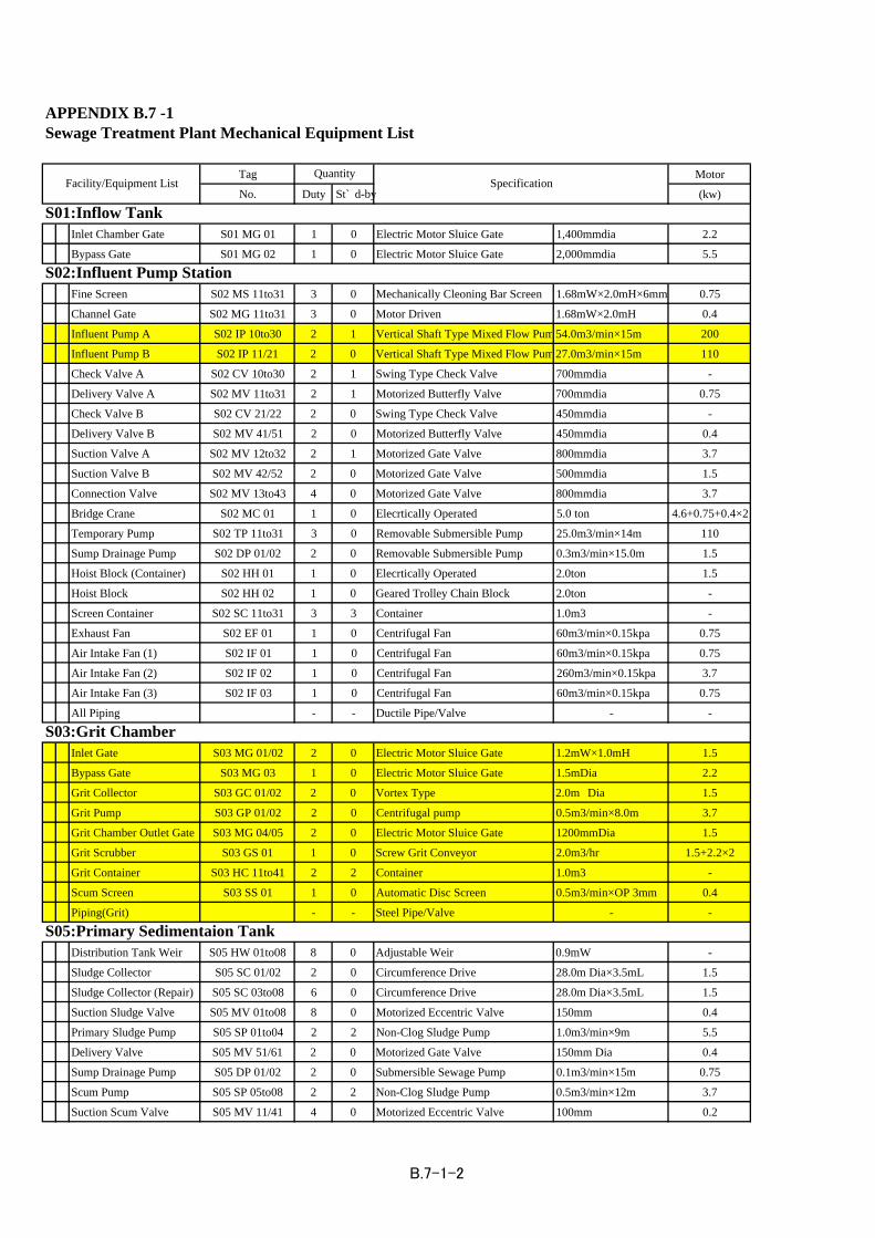
Tag Motor
No. Duty St`d-by (kw)
Inlet Chamber Gate S01 MG 01 1 0 Electric Motor Sluice Gate 1,400mmdia 2.2
Bypass Gate S01 MG 02 1 0 Electric Motor Sluice Gate 2,000mmdia 5.5
Fine Screen S02 MS 11to31 3 0 Mechanically Cleoning Bar Screen 1.68mW×2.0mH×6mm 0.75
Channel Gate S02 MG 11to31 3 0 Motor Driven 1.68mW×2.0mH 0.4
Influent Pump A S02 IP 10to30 2 1 Vertical Shaft Type Mixed Flow Pum54.0m3/min×15m 200
Influent Pump B S02 IP 11/21 2 0 Vertical Shaft Type Mixed Flow Pum27.0m3/min×15m 110
Check Valve A S02 CV 10to30 2 1 Swing Type Check Valve 700mmdia -
Delivery Valve A S02 MV 11to31 2 1 Motorized Butterfly Valve 700mmdia 0.75
Check Valve B S02 CV 21/22 2 0 Swing Type Check Valve 450mmdia -
Delivery Valve B S02 MV 41/51 2 0 Motorized Butterfly Valve 450mmdia 0.4
Suction Valve A S02 MV 12to32 2 1 Motorized Gate Valve 800mmdia 3.7
Suction Valve B S02 MV 42/52 2 0 Motorized Gate Valve 500mmdia 1.5
Connection Valve S02 MV 13to43 4 0 Motorized Gate Valve 800mmdia 3.7
Bridge Crane S02 MC 01 1 0 Elecrtically Operated 5.0 ton 4.6+0.75+0.4×2
Temporary Pump S02 TP 11to31 3 0 Removable Submersible Pump 25.0m3/min×14m 110
Sump Drainage Pump S02 DP 01/02 2 0 Removable Submersible Pump 0.3m3/min×15.0m 1.5
Hoist Block (Container) S02 HH 01 1 0 Elecrtically Operated 2.0ton 1.5
Hoist Block S02 HH 02 1 0 Geared Trolley Chain Block 2.0ton -
Screen Container S02 SC 11to31 3 3 Container 1.0m3 -
Exhaust Fan S02 EF 01 1 0 Centrifugal Fan 60m3/min×0.15kpa 0.75
Air Intake Fan (1) S02 IF 01 1 0 Centrifugal Fan 60m3/min×0.15kpa 0.75
Air Intake Fan (2) S02 IF 02 1 0 Centrifugal Fan 260m3/min×0.15kpa 3.7
Air Intake Fan (3) S02 IF 03 1 0 Centrifugal Fan 60m3/min×0.15kpa 0.75
All Piping - - Ductile Pipe/Valve - -
Inlet Gate S03 MG 01/02 2 0 Electric Motor Sluice Gate 1.2mW×1.0mH 1.5
Bypass Gate S03 MG 03 1 0 Electric Motor Sluice Gate 1.5mDia 2.2
Grit Collector S03 GC 01/02 2 0 Vortex Type 2.0m Dia 1.5
Grit Pump S03 GP 01/02 2 0 Centrifugal pump 0.5m3/min×8.0m 3.7
Grit Chamber Outlet Gate S03 MG 04/05 2 0 Electric Motor Sluice Gate 1200mmDia 1.5
Grit Scrubber S03 GS 01 1 0 Screw Grit Conveyor 2.0m3/hr 1.5+2.2×2
Grit Container S03 HC 11to41 2 2 Container 1.0m3 -
Scum Screen S03 SS 01 1 0 Automatic Disc Screen 0.5m3/min×OP 3mm 0.4
Piping(Grit) - - Steel Pipe/Valve - -
Distribution Tank Weir S05 HW 01to08 8 0 Adjustable Weir 0.9mW -
Sludge Collector S05 SC 01/02 2 0 Circumference Drive 28.0m Dia×3.5mL 1.5
Sludge Collector (Repair) S05 SC 03to08 6 0 Circumference Drive 28.0m Dia×3.5mL 1.5
Suction Sludge Valve S05 MV 01to08 8 0 Motorized Eccentric Valve 150mm 0.4
Primary Sludge Pump S05 SP 01to04 2 2 Non-Clog Sludge Pump 1.0m3/min×9m 5.5
Delivery Valve S05 MV 51/61 2 0 Motorized Gate Valve 150mm Dia 0.4
Sump Drainage Pump S05 DP 01/02 2 0 Submersible Sewage Pump 0.1m3/min×15m 0.75
Scum Pump S05 SP 05to08 2 2 Non-Clog Sludge Pump 0.5m3/min×12m 3.7
Suction Scum Valve S05 MV 11/41 4 0 Motorized Eccentric Valve 100mm 0.2
S02:Influent Pump Station
S05:Primary Sedimentaion Tank
S01:Inflow Tank
APPENDIX B.7 -1
SpecificationFacility/Equipment ListQuantity
Sewage Treatment Plant Mechanical Equipment List
S03:Grit Chamber
B.7-1-2

Tag Motor
No. Duty St`d-by (kw)
Hoist Biock S05 HH 01 1 0 Geared Trolley Chain Block 1.0ton -
Exhaust Fan S05 EF 01/02 2 0 Centrifugal Fan 12m3/min×0.15kpa 0.2
Piping(Sludge/Scum) - - Ductile Pipe/Valve - -
Air Blower S08 AB 01to05 3 2 Multistage Turbo Blower 255m3/min×50kpa 315+0.4
Air Filter S08 AF 01to05 3 2 Automatic Air Filter 255m3/min 0.2
Delivery Valve S08 MV 01to05 3 2 Motorized Gate Valve 400mm Dia 0.75
Clear Water Supply Pump S08 WP 01/02 1 1 Volute Pump 0.3m3/min×20m 2.2
Hoist Block S08 MC 01 1 0 5.0 ton 4.6+0.75+0.75×2
Sump Drainge Pump S08 DP 01 1 0 Submersible Sewoge Pump 0.1m3/min×7.0m 0.4
Cleor Water Tank S08 WT 01 1 0 PVC Tank 5 m3 -
All Piping - - Ductile Pipe/Valve - -
Return Sludge Inlet Weir S10 HW 01to12 12 0 Adjustable Weir 0.6mW -
Distribution Tank Weir S10 HW 13to24 12 0 Adjustable Weir 0.9mW -
Sludge Collector S10 SC 01/02 2 0 Circumference Drive 28.0m Dia×3.5mH 1.5
Sludge Collector (Repair) S10 SC 03to12 10 0 Circumference Drive 28.0m Dia×3.5mH 1.5
Return Sludge pump S11 SP 01to05 3 2 Vertical Shaft Type Mixed Flow Pum32m3/min×6m 55Waste Sludge pump S11 SP 06/07 1 1 Non-Clog Sludge pump 4.7m3/min×10m 22Delivery Valve S11 MV 01to05 3 2 Motorized Gate Valve 500mm Dia 0.75Suction Valve S11 MV 06to10 3 2 Motorized Gate Valve 600mm Dia 1.5Partition Valve S11 MV 11to14 4 0 Motorized Butterfly Valve 900mm Dia 3.7Check Valve S11 CV 01to05 5 0 Swing Type Check Valve 500mmDia -Bridge Crane S11 MC 01 1 0 Elecrtically Operated 5.0 ton 4.6+0.75+0.4×2Sump Drainage Pump S11 DP 01/02 1 1 Removable Submersible Pump 0.3m3/min×10m 1.5Connection Valve A S11 MV 15/16 2 0 Motorized Gate Valve 1100mmDia 5.5Connection Valve B S11 MV 17 1 0 Motorized Gate Valve 1200mmDia 7.5All Piping - - Ductile Pipe/Valve - -
Inlet Chamber Gate S12 MG 01 1 0 Electric Motor Sluice Gate 1,500mmDia 3.7Discharge Pump A S12 CP 01to03 2 1 Vertical Shaft Type Mixed Flow Pum54.0m3/min×15m 200Discharge Pump B S12 CP 04/05 2 0 Vertical Shaft Type Mixed Flow Pum27.0m3/min×15m 110Suction Valve A S12 MV 06to08 2 1 Motorized Gate Valve 800mmDia 3.7Suction Valve B S12 MV 09/10 2 0 Motorized Gate Valve 500mmDia 1.5Check Valve S12 CV 01to03 2 1 Swing Type Check Valve 700mmDia -Check Valve S12 CV 04/05 2 0 Swing Type Check Valve 450mmDia -Delivery Valve A S12 MV 01to03 2 1 Motorized Butterfly Valve 700mmDia 0.75Delivery Valve B S12 MV 04/05 2 0 Motorized Butterfly Valve 450mmDia 0.4Connection Valve S12 MV 11to14 4 0 Motorized Gate Valve 800mmDia 3.7Bridge Crane S12 MC 01 1 0 Elecrtically Operated 5.0 ton 4.6+0.75+0.4×2Sump Drainage Pump S12 DP 01/02 1 1 Removable Submersible Pump 0.3m3/min×10.0m 1.5Temporary Pump S12 TP 01to03 3 0 Removable Submersible Pump 25.0m3/min×15m 110Air Intake Fan A S12 IF 01 1 0 Centrifugal Fan 260m3/min×0.15kpa 3.7Air Intake Fan B S12 IF 02 1 0 Centrifugal Fan 60m3/min×0.15kpa 0.75All Piping - - Ductile Pipe/Valve - -
Inlet Weir S21 HW 01/02 2 0 Adjustable Weir 0.6mW -Thickener Sludge Collectar S21 GS 01/02 2 0 Center Drive 20.0m Dia×3.5mH 0.75
S11:Return Sludge pump Station
S12:Discharge Pump Station
Mechanical Equipment List
QuantitySpecification
S08:Blower House
Facility/Equipment List
S21:Gravity Thickener
S10:Secondary Sedimentation tank
B.7-1-3

Tag MotorNo. Duty St`d-by (kw)
Thickened Sludge pump S21 SP 01/02 1 1 Non-Clog Sludge Pump 1.0m3/min×5m 3.7Suction Sludge Valve S21 MV 01/02 2 0 Motorized Eccentric Valve 150mm Dia 0.2Sump Drainage Pump S21 DP 01 1 0 Submersible Sewage Pump 0.1m3/min×7m 0.4Hoist Block S021 HH 01 1 - Geared Trolley Chain Block 1ton -Exhaust Fan S21 EF 01 1 - Centrifugal Fan 12m3/min×0.15kpa 0.2Piping(sludge) - - Ductile Pipe/Valve - -
Sludge Pump S23 SP 01/02 1 1 Non-Clog Sludge Pump 5.5m3/min×12m 22Desulfurizer S23 DF 01 1 0 Water Spray Type 460m3/hr -Sump Drainage Pump S23 DP 01 1 0 Submersible Sewoge Pump 0.3m3/min×15.0m 1.5Sludge Valve S23 MV 01to05 5 0 Motorized Gate Valve 250mm Dia 0.4Inhalation Fan S23 IF 01to04 2 2 Centrifugal Fan 40m3/min 1.5Piping(sluge) - - Ductile Pipe/Valve - -
Waste Sludge Mixer S24 SM 01/02 2 0 Vertical Propeller Mixer Dia.2,000mm 7.5Waste Sludge Feed Pump S24 SP 03to05 2 1 Progresive Cavity Type 34~104m3/hr×20m 30Mechanical Thickener S24 MT 01to03 2 1 Screw Press Thickener 75m3/hr (3.0m2) 1.5+0.75+0.75Polymer Feeder S24 PF 01/02 2 0 Constant Chemical Feeder 2,000cc/min 0.4Polymer Tank S24 PT 01/02 2 0 Vertical Cylindrical Tank 7m3 3.7Polymer Feed Pump S24 PP 01to03 2 1 Progresive Cavity Pump 0.8^2.7m3/hr×20m 1.5Thickened Sludge Mixer S24 SM 03/04 2 0 Vertical Propeller Mixer Dia.1,500mm 7.5Thickened SludgePump S24 SP 01/02 1 1 Non-Clog Sludge Pump 1.0m3/min×22m 11Siudge Grinder S24 SG 01 1 0 In-Pipeline Type 1.5m3/min 3.7Air Compressor S24 AC 01/02 1 1 Control Switch Type 600L/min×0.83Mpa 5.5Air Dryer S24 AD 01 1 0 Refrigerating Type 600L/min 0.2Hoist Block S24 HH 01to03 3 0 Geared Trolley Chain Block 2.0t -Digested Sludge Mixer S24 SM 05/06 2 0 Vertical Propeller Mixer Dia.2,000mm 7.5Sludge Feed Pump S24 SP 06to08 2 1 Progresive Cavity Type 7.5^23m3/hr×20m 7.5Dewatering Machine S24 DM 01to03 2 1 Screw Press Type 450kg-ds/hr 3.7+1.5Polymer Feeder S24 PF 03/04 2 0 Constant Chemical Feeder 4,000cc/min 0.4Polymer Tank S24 PT 03/04 2 0 Vertical Cylindrical Tank 10m3 5.5Polymer Feed Pump S24 PP 04to06 2 1 Progresive Cavity Pump 1.5^4.8m3/hr×20m 2.2Polymer Container S24 PC 01to08 8 0 Polymer Container 1.0m3 -Waste Water Mixer S24 SM 07 1 0 Vertical Propeller Mixer Dia.2,000mm 7.5Waste Water Pump S24 SP 09/10 1 1 Non-Clog Sludge Pump 3.0m3/min×17.0m 22Hoist Block S24 HH 04 1 0 Geared Trolley Chain Block 3Ton -Hoist Block Dewateing S24 HH05to07 3 0 Geared Trolley Chain Block 3.0t -Hoist Block S24 HH 08/09 2 0 Geared Trolley Chain Block 0.5t -Sump Drainage Pump S24 DP 01to04 2 2 Submersible Sewage Pump 0.3m3/min×10.0m 1.5Scrubber S24 BS 01/02 1 0 Biological Scrubber 90m3/min -Odor Fan S24 EX 01to04 1 1 GRP Centrifugal Fan 90m3/min×2.5kpa 5.5Mist Separator S24 HS 01/02 1 0 Mist Separator 180m3/min -Elutriation Water Pump S24 OP 01/02 1 1 Volute Pump 0.17m3/min×25.0m 3.7Treated Water Supply Unit S24 SU 01/02 1 1 Pressure Tank Type 0.3m3/min×25m 3.7Desulfurize Pump S24 VP 01/02 1 1 Volute Pump 6.1m3/min×23m 45Water Supply Unit S24 SU 03/04 1 1 Pressure Tank Type 2.2m3/min×40m 15Strainer Odor Scrubber S24 AS 01 1 0 Automatic Backwashing Type 0.34m3/min 0.4Strainer Grit Scrubber S24 AS 02 1 0 Automatic Backwashing Type 0.3m3/min 0.4Strainer Desulfurizer S24 AS 03 1 0 Automatic Backwashing Type 6.1m3/min 0.4Treated Water Valve S24 CV 01 1 0 Motorized Butterfly Valve Dia.400mm 0.4
Mechanical Equipment List
S23:Digester & Pump House
QuantitySpecificationFacility/Equipment List
S24:Sludge Treatment Building
B.7-1-4

Tag MotorNo. Duty St`d-by (kw)
Piping(sludge) - - Ductile Pipe/Valve - -Piping(Polymer) - - PVCLining Steel Pipe/Valve - -
Cake Conveyor S25 CC 01to03 2 1 Belt Conveyor 600mmW×19mL 1.5Cake Hopper S25 CH 01to06 4 2 Motor Driven Cut Gate Type 15m3 2.2×2Cake Tripper S25 CT 01to03 2 1 Motor Driven 0.4
Gas Holder S26 GH 01/02 2 0 Wet Type Gas Holder 1300m3 -
Coal Boiler S27 CB 01/02 1 1 - 4.5ton/hr 11Coal Grinder S27 CG 01/02 1 1 Two Axis Grinder - 11Coal Conveyor S27 CO 01 1 0 Tilt10m,Level28m - 22Ash Conveyor (1) S27 AO 01 1 0 Belt Conveyor 28mL 1.5Ash Conveyor (2) S27 AO 02 1 0 Belt Conveyor 31mL 1.5Clear Water Tank S27 WT 01 1 0 PVC Tank 10m3 -Watar Supply Pump S27 SP 01/02 1 1 Volute Pump 0.2m3/min 5.5Water Softening Unir S27 HS 01/02 1 1 0.22m3/min 200wSoft Water Pump S27 SP 03/04 1 1 Multistage Pump 2.2m3/min 45Generator S27 WW 01 1 0 12m3 -Heating Pump S27 SP 05/06 1 1 0.9m3/min 11Heat Exchanger S27 HE 01 1 0 0.9m3/min -Exhaust Fan S27 EF 01 1 0 0.75Piping(Steam/Wayer) - - Steel Pipe/Valve - -
S25:Hopper House
Facility/Equipment ListQuantity
Specification
Mechanical Equipment List
S27:Boiler Building
S26:Gas Holder
B.7-1-5

Tag MotorNo. Duty St`d-by (kw)
Inflow Valve S51 MV 01 1 0 Motorized Gate Valve 600mmdia 1.5Fine Screen S51 MS 01 1 0 Mechanically Cleoning Bar Screen 0.6mW×0.6mH×25mm 1.5
Sump Drainage Pump S51 DP 01/02 2 0 Removable Submersible Pump 0.3m3/min×15.0m 1.5Hoist Block S51 HH 01/02 2 0 Geared Trolley Chain Block 3.0ton -Exhaust Fan S51 EF 01 1 0 Centrifugal Fan 55m3/min 3.7Air Intake Fan S51 IF 01 1 0 Centrifugal Fan 105m3/min 5.5
Sump Drainage Pump S52 DP 01 1 0 Removable Submersible Pump 0.3m3/min×15.0m 1.5Hoist Block S52 HH 01 1 0 Geared Trolley Chain Block 2.0ton -Exhaust Fan S52 EF 01 1 0 Centrifugal Fan 8m3/min 0.4Air Intake Fan S52 IF 01 1 0 Centrifugal Fan 14m3/min 0.75
Inflow Valve S53 MV 01/02 2 0 Motorized Gate Valve 600mmdia 1.5Fine Screen S53 MS 01/02 2 0 Mechanically Cleoning Bar Screen 0.6mW×0.6mH×25mm 1.5
Sump Drainage Pump S53 DP 01/02 1 0 Removable Submersible Pump 0.3m3/min×15.0m 1.5Hoist Block S53 HH 01 1 0 Motor driven hoist 3.0ton 1.5Hoist Block S53 HH 02 1 0 Geared Trolley Chain Block 1.0ton -Exhaust Fan S53 EF 01 1 0 Centrifugal Fan 55m3/min 3.7Air Intake Fan S53 IF 01 1 0 Centrifugal Fan 105m3/min 5.5
Inflow Valve S54 MV 01 1 0 Motorized Gate Valve 800mmdia 2.2Fine Screen S54 MS 01 1 0 Mechanically Cleoning Bar Screen 1.2mW×1.2mH×6mm 1.5
Sump Drainage Pump S54 DP 01/02 2 0 Removable Submersible Pump 0.3m3/min×15.0m 1.5Hoist Block S54 HH 01 1 0 Geared Trolley Chain Block 2.0ton -Exhaust Fan S54 EF 01 1 0 Centrifugal Fan 13m3/min 0.75Air Intake Fan S54 IF 01 1 0 Centrifugal Fan 22m3/min 1.5
Inflow Valve S55 MV 01/04 4 0 Motorized Gate Valve 600mmdia 1.5
Sump Drainage Pump S55 DP 01/02 2 0 Removable Submersible Pump 0.3m3/min×15.0m 1.5Hoist Block S55 HH 01 1 0 Motor driven hoist 5.0ton 5.5Exhaust Fan S55 EF 01 1 0 Centrifugal Fan 13m3/min 0.75
27m3/min×10m 75S55 SP 01to04 2 2 Horizontal Shaft Volute Type MixedFlow Pump
S55:PS No.6
Sewage Pump
22
Screening Grinder S54 SG 01 1 0 Motorized overlapping double axislayered cutter type Valve
0.4m3/hr 7.5
7.5
S54:PS No.4
Sewage Pump S54 SP 01to03 2 1 Horizontal Shaft Volute Type MixedFlow Pump
7.5m3/min×7.0m
14.0m3/min×9m 37
Screening Grinder S53 SG 01/02 2 0 Motorized overlapping double axislayered cutter type Valve
0.4m3/hr
0.4m3/hr 7.5
S53:PS No.3
Sewage Pump S53 SP 01to05 3 2 Horizontal Shaft Volute Type MixedFlow Pump
Horizontal Shaft Volute Type MixedFlow Pump
7.5m3/min×7m 22
Screening Grinder S52 SG 01 1 0 Motorized overlapping double axislayered cutter type Valve
Sewage Pump S52 SP 01/03 2 1
0.4m3/hr 7.5Screening Grinder
45
1 0 Motorized overlapping double axislayered cutter type Valve
S51:PS No.1
S52:PS No.2
Horizontal Shaft Volute Type MixedFlow Pump
Sewage Pump S51 SP 01to04 2 2 14.0m3/min×10m
S51 SG 01
APPENDIX B.7 -2
Intermediate Pump Stations Mechanical Equipment List
Facility/Equipment ListQuantity
Specification
B.7-2-1

Tag MotorNo. Duty St`d-by (kw)
Air Intake Fan S55 IF 01 1 0 Centrifugal Fan 22m3/min 1.5
Inflow Valve S56 MV 01 1 0 Motorized Gate Valve 1000mmdia 3.7Fine Screen S56 MS01/ 02 2 0 Mechanically Cleoning Bar Screen 1.0mW×1.0mH×25mm 1.5Sewage Pump S56 SP 01/02 2 1 Vertical Shaft Type Mixed Flow Pum27.0m3/min×11m 75
Delivery Valve S56 MV 02/03 2 0 Motorized Gate Valve 400mmdia 0.75Delivery Valve S56 MV 04 1 0 Motorized Gate Valve 500mmdia 1.5Connection Valve S56 MV 05/06 2 0 Motorized Gate Valve 800mmdia 3.7
Sump Drainage Pump S56 DP 01/02 2 0 Removable Submersible Pump 0.3m3/min×15.0m 1.5Bridge Crane S56 MC 01 1 0 Elecrtically Operated 5.0 ton 4.6+0.75+0.4×2Exhaust Fan S56 EF 01 1 0 Centrifugal Fan 60m3/min 0.75Air Intake Fan S56 IF 01 1 0 Centrifugal Fan 60m3/min 0.75Air Intake Fan S56 IF 02 1 0 Centrifugal Fan 260m3/min 3.7Air Intake Fan S56 IF 03 1 0 Centrifugal Fan 60m3/min 0.75
Inflow Valve S57 MV 01 1 0 Motorized Gate Valve 800mmdia 2.2Fine Screen S57 MS 01 1 0 Mechanically Cleoning Bar Screen 0.8mW×0.8mH×6mm 1.5
Connection Valve S57 MV 02/05 4 0 Motorized driven Gate Valve 600mmdia 0.75Sump Drainage Pump S57 DP 01/02 2 0 Removable Submersible Pump 0.3m3/min×15.0m 1.5Hoist Block S57 HH 01/02 2 0 Geared Trolley Chain Block 3.0ton -Exhaust Fan S57 EF 01 1 0 Centrifugal Fan 55m3/min 3.7Air Intake Fan S57 IF 01 1 0 Centrifugal Fan 105m3/min 5.5
Hoist Block S58 HH 01 1 0 Geared Trolley Chain Block 1.0ton -Exhaust Fan S58 EF 01 1 0 Centrifugal Fan 4m3/min 0.4Air Intake Fan S58 IF 01 1 0 Centrifugal Fan 6m3/min 0.4
Hoist Block S59 HH 01 1 0 Geared Trolley Chain Block 1.0ton -Exhaust Fan S59 EF 01 1 0 Centrifugal Fan 4m3/min 0.4Air Intake Fan S59 IF 01 1 0 Centrifugal Fan 6m3/min 0.4
Hoist Block S60 HH 02 1 0 Geared Trolley Chain Block 1.0ton -Exhaust Fan S60 EF 01 1 0 Centrifugal Fan 4m3/min 0.4Air Intake Fan S60 IF 01 1 0 Centrifugal Fan 6m3/min 0.4
Mechanical Equipmen
Facility/Equipment ListQuantity
Specification
S59:PS No.15Sewage Pump
151.4m3/min×24m
11
18.5
S60:PS No.16Sewage Pump S60 SP 01to03 2 1 Horizontal Shaft Volute Type Mixed
Flow Pump
S59 SP 01to03 2 1 Horizontal Shaft Volute Type MixedFlow Pump
4.2m3/min×11m
7.5
S58:PS No.11Sewage Pump S58 SP 01to03 2 1 Horizontal Shaft Volute Type Mixed
Flow Pump1.9m3/min×8.0m
7.5m3/min×11m 30
Screening Grinder S57 SG 01 1 0 Motorized overlapping double axislayered cutter type Valve
0.4m3/hr
S57 SP 01to05 3 2 Horizontal Shaft Volute Type MixedFlow Pump
S57:PS No.10
Sewage Pump
30
Screening Grinder S56 SG 01/02 2 0 Motorized overlapping double axislayered cutter type Valve
0.4m3/hr 7.5
14m3/min×11m 45
Sewage Pump S56 SP 05/06 2 0 Horizontal Shaft Volute Type MixedFlow Pump
7.5m3/min×11m
S56:PS No.7
Sewage Pump S56 SP 03/04 2 0 Horizontal Shaft Volute Type MixedFlow Pump
B.7-2-2

Tag MotorNo. Duty St`d-by (kw)
Hoist Block S61 HH 01 1 0 Geared Trolley Chain Block 1.0ton -Exhaust Fan S61 EF 01 1 0 Centrifugal Fan 1m3/min 0.2Air Intake Fan S61 IF 01 1 0 Centrifugal Fan 1.5m3/min 0.2
Sump Drainage Pump S62 DP 01 1 0 Removable Submersible Pump 0.3m3/min×15.0m 1.5Hoist Block S62 HH 01 1 0 Geared Trolley Chain Block 1.0ton -Exhaust Fan S62 EF 01 1 0 Centrifugal Fan 4m3/min 0.4Air Intake Fan S62 IF 01 1 0 Centrifugal Fan 6m3/min 0.4
Hoist Block S63 HH 01 1 0 Geared Trolley Chain Block 1.0ton -Exhaust Fan S63 EF 01 1 0 Centrifugal Fan 2m3/min 0.2Air Intake Fan S63 IF 01 1 0 Centrifugal Fan 3m3/min 0.2
Screenings Cage S64 HH 01/02 2 0 Box shape with chain 5mm, type 316 -
Screenings Cage S65 HH 01/02 2 0 Box shape with chain 5mm, type 316 -
Screenings Cage S62 HH 01/02 2 0 Box shape with chain 5mm, type 316 -
Screenings Cage S67 HH 01/02 2 0 Box shape with chain 5mm, type 316 -
Mechanical Equipmen
Facility/Equipment ListQuantity
Specification
0.84m3/min×15m 7.5
0.84m3/min×30m 18.5
0.84m3/min×15m
22
7.5
S67:PS No.IHSewage Pump S67 SP 01/02 1 1 Submersible non-clog Type Vorute
Type Flow Pump
S66 SP 01/02 1 1 Submersible non-clog Type VoruteType Flow Pump
S66:PS No.37Sewage Pump
S65:PS No.34Sewage Pump S65 SP 01/02 1 1 Submersible non-clog Type Vorute
Type Flow Pump
11
S64:PS No.28Sewage Pump S64 SP 01/02 1 1 Submersible non-clog Type Vorute
Type Flow Pump1.3m3/min×28m
30
S63:PS No.24Sewage Pump S63 SP 01/02 1 1 Horizontal Shaft Volute Type Mixed
Flow Pump1.3m3/min×15m
30
S62:PS No.21Sewage Pump S62 SP 01/02 1 1 Horizontal Shaft Volute Type Mixed
Flow Pump3.3m3/min×19m
S61:PS No.17Sewage Pump S61 SP 01/02 1 1 Horizontal Shaft Volute Type Mixed
Flow Pump4.2m3/min×18m
B.7-2-3

Appendix B-8
Sewer Pipeline List

APPENDIX B-8 Sewer Pipeline List in ASTANA City
1 Summary of the existing pipelinesTOTAL LENGTH 226578.42 m 100.0%asbestos-cement 45461.51 m 20.1%cast-iron 85380.96 m 37.7%ceramics 32574.45 m 14.4%ferroconcrete 27929.7 m 12.3%polyethylene 2240 m 1.0%steel 32264.8 m 14.2%other 727 m 0.3%
2 Manhole numbersN= 5279
3 Detailed List of Ppelines and Manholes
1973 AL Abai St. 117-a 150 asbestos/cement 63.8 51976 SA Abai St. 88 200 asbestos/cement 771987 AL Abai St. 115 150 asbestos/cement 102 71991 AL Abai St. 138 150 asbestos/cement 122.9 61988 AL Abai St. 187 150 asbestos/cement 77.4 21988 AL Abai St. 187 200 asbestos/cement 88.3 21988 AL Abai St. 187 250 asbestos/cement 36.6 41965 AL Abai St. 197 250 asbestos/cement 312.5 Abai St 199,201,203,205,207, Sembinov St 44,45, Lomonosov 551965 AL Abai St. 197 200 asbestos/cement 83.9 Abai St 199,201,203,205,207, Sembinov St 44,45, Lomonosov 551991 SA Abai St. 322 100 asbestos/cement 15 11972 AL Abai St. 121-a 150 asbestos/cement 60.8 41991 AL Abai St. 221/2 150 asbestos/cement 60.3 41986 AL Abylai-Khan 19/1. 150 asbestos/cement 109.5 51992 AL Abylai-Khan 28/4. 200 asbestos/cement 175.1 71990 AL Abylai-Khan 5/3. 150 asbestos/cement 139.9 61983 AL Abylai-Khan 2 200 asbestos/cement 108.4 41984 AL Abylai-Khan 5 200 asbestos/cement 150 81984 AL Abylai-Khan 7 300 asbestos/cement 89.5 21984 AL Abylai-Khan 7 200 asbestos/cement 30.8 31988 AL Abylai-Khan 9 150 asbestos/cement 18.81986 AL Abylai-Khan 10 150 asbestos/cement 42.5 21983 AL Abylai-Khan 22 300 asbestos/cement 68 21991 AL Abylai-Khan 39 150 asbestos/cement 80.4 51989 AL Abylai-Khan 10/2. 150 asbestos/cement 22.5 21988 AL Abylai-Khan 17/2. 150 asbestos/cement 39.9 21987 AL Abylai-Khan 21/2. 300 asbestos/cement 76.1 11987 AL Abylai-Khan 21/2. 200 asbestos/cement 43.8 1
B-8-1
No.1Pipe material Pipe length Manhole
number DescriptionYear ofconstruction
Location DiameterDistrict House No.

1987 AL Abylai-Khan 21/2. 150 asbestos/cement 109.1 71986 AL Abylai-Khan 24/1. 200 asbestos/cement 82.5 41986 AL Abylai-Khan 25/2. 150 asbestos/cement 39.3 51987 AL Abylai-Khan 27/3. 250 asbestos/cement 129.3 111993 AL Abylai-Khan 28/3. 200 asbestos/cement 58.4 21993 AL Abylai-Khan 28/3. 150 asbestos/cement 166.1 9 and house 28/61986 AL Abylai-Khan 29/3. 250 asbestos/cement 13.51991 AL Abylai-Khan 3/2. 150 asbestos/cement 12 11991 AL Abylai-Khan 33/2 150 asbestos/cement 76.3 41990 AL Abylai-Khan 39/1 250 asbestos/cement 180 81987 AL Abylai-Khan 8/1. 150 asbestos/cement 114 51994 SA Agrogorodok 18 150 asbestos/cement 136.3 71994 AL Al-Farabi 2 150 asbestos/cement 33.9 21989 AL Al-Farabi 14 200 asbestos/cement 145.5 41989 AL Al-Farabi 14 150 asbestos/cement 148.9 81991 AL Al-Farabi 15 250 asbestos/cement 60.9 11991 AL Al-Farabi 15 200 asbestos/cement 52 61991 AL Al-Farabi 35 150 asbestos/cement 132 71992 AL Al-Farabi 41 200 asbestos/cement 134.9 51994 AL Al-Farabi 42 150 asbestos/cement 48.5 31994 AL Al-Farabi 42 200 asbestos/cement 39 21997 AL Al-Farabi 62 150 asbestos/cement 50.7 21997 AL Al-Farabi 81 150 asbestos/cement 24.7 21997 AL Al-Farabi 81 150 asbestos/cement 24.9 21991 AL Al-Farabi 1/1. 150 asbestos/cement 38.1 31991 AL Al-Farabi 1/1. 200 asbestos/cement 62.7 11990 AL Al-Farabi 41/1. 150 asbestos/cement 33.9 51993 AL Al-Farabi 5/1.5/2 200 asbestos/cement 25 11993 AL Al-Farabi 5/1.5/2 150 asbestos/cement 116.8 41998 AL Al-Farabi 81/1 150 asbestos/cement 128.4 51994 AL Al-Farabi p. 11-b 150 asbestos/cement 74.3 41994 AL Al-Farabi p. 11-b 200 asbestos/cement 221.1 21962 SA Auezov St 117 150 asbestos/cement 39.5 11990 SA Auezov St 54/1 150 asbestos/cement 64.8 51981 SA Auezov St 56 150 asbestos/cement 100.3 71980 SA Auezov St 116 200 asbestos/cement 194 61976 SA Auezov St 132-a 150 asbestos/cement 50.6 21976 SA Auezov St 132-a 200 asbestos/cement 173.8 41976 SA Auezov St 132-a 250 asbestos/cement 195.2 61976 SA Auezov St 132-a 300 asbestos/cement 96 31992 SA Baitursynov St 109 150 asbestos/cement 105.8 31992 SA Baitursynov St 109 200 asbestos/cement 33.3 21997 SA Begeldinov St 41 200 asbestos/cement 27.5 31997 SA Begeldinov St 41 300 asbestos/cement 406.4 13
B-8-2
Manholenumber DescriptionHouse No. Diameter Pipe material Pipe length
No.2 Year ofconstruction
District Location
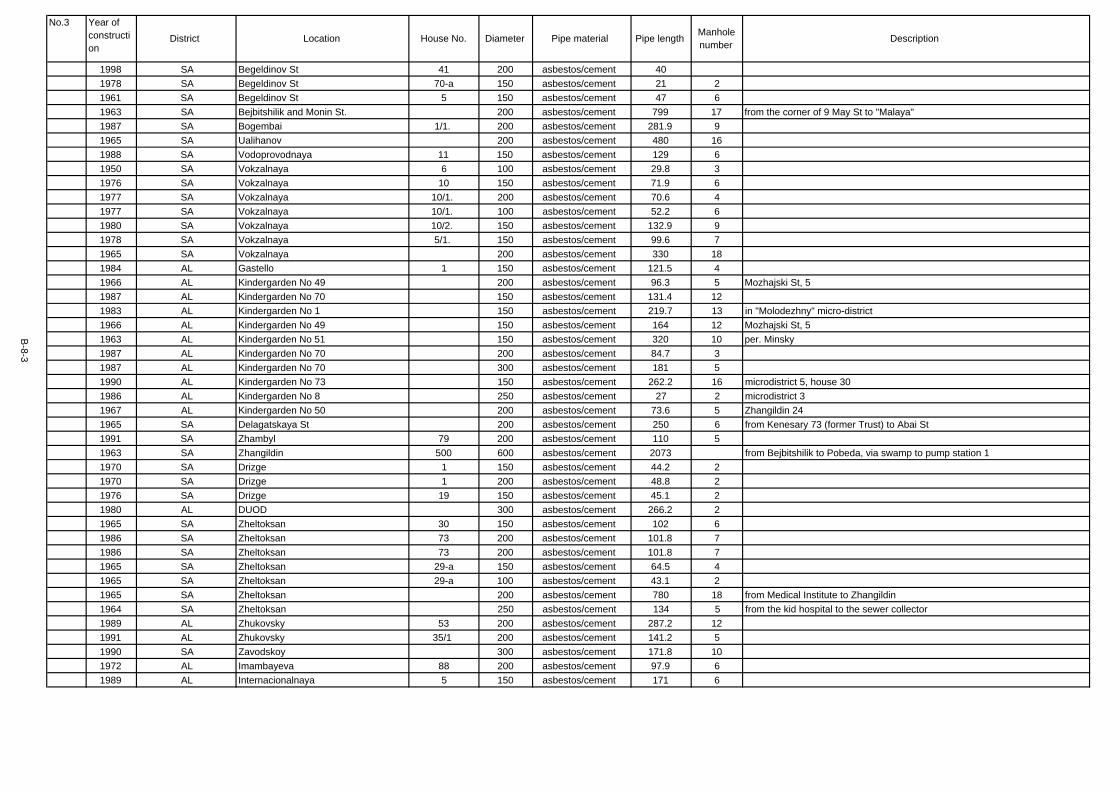
1998 SA Begeldinov St 41 200 asbestos/cement 401978 SA Begeldinov St 70-a 150 asbestos/cement 21 21961 SA Begeldinov St 5 150 asbestos/cement 47 61963 SA Bejbitshilik and Monin St. 200 asbestos/cement 799 17 from the corner of 9 May St to "Malaya"1987 SA Bogembai 1/1. 200 asbestos/cement 281.9 91965 SA Ualihanov 200 asbestos/cement 480 161988 SA Vodoprovodnaya 11 150 asbestos/cement 129 61950 SA Vokzalnaya 6 100 asbestos/cement 29.8 31976 SA Vokzalnaya 10 150 asbestos/cement 71.9 61977 SA Vokzalnaya 10/1. 200 asbestos/cement 70.6 41977 SA Vokzalnaya 10/1. 100 asbestos/cement 52.2 61980 SA Vokzalnaya 10/2. 150 asbestos/cement 132.9 91978 SA Vokzalnaya 5/1. 150 asbestos/cement 99.6 71965 SA Vokzalnaya 200 asbestos/cement 330 181984 AL Gastello 1 150 asbestos/cement 121.5 41966 AL Kindergarden No 49 200 asbestos/cement 96.3 5 Mozhajski St, 51987 AL Kindergarden No 70 150 asbestos/cement 131.4 121983 AL Kindergarden No 1 150 asbestos/cement 219.7 13 in "Molodezhny" micro-district1966 AL Kindergarden No 49 150 asbestos/cement 164 12 Mozhajski St, 51963 AL Kindergarden No 51 150 asbestos/cement 320 10 per. Minsky1987 AL Kindergarden No 70 200 asbestos/cement 84.7 31987 AL Kindergarden No 70 300 asbestos/cement 181 51990 AL Kindergarden No 73 150 asbestos/cement 262.2 16 microdistrict 5, house 301986 AL Kindergarden No 8 250 asbestos/cement 27 2 microdistrict 31967 AL Kindergarden No 50 200 asbestos/cement 73.6 5 Zhangildin 241965 SA Delagatskaya St 200 asbestos/cement 250 6 from Kenesary 73 (former Trust) to Abai St1991 SA Zhambyl 79 200 asbestos/cement 110 51963 SA Zhangildin 500 600 asbestos/cement 2073 from Bejbitshilik to Pobeda, via swamp to pump station 11970 SA Drizge 1 150 asbestos/cement 44.2 21970 SA Drizge 1 200 asbestos/cement 48.8 21976 SA Drizge 19 150 asbestos/cement 45.1 21980 AL DUOD 300 asbestos/cement 266.2 21965 SA Zheltoksan 30 150 asbestos/cement 102 61986 SA Zheltoksan 73 200 asbestos/cement 101.8 71986 SA Zheltoksan 73 200 asbestos/cement 101.8 71965 SA Zheltoksan 29-a 150 asbestos/cement 64.5 41965 SA Zheltoksan 29-a 100 asbestos/cement 43.1 21965 SA Zheltoksan 200 asbestos/cement 780 18 from Medical Institute to Zhangildin1964 SA Zheltoksan 250 asbestos/cement 134 5 from the kid hospital to the sewer collector1989 AL Zhukovsky 53 200 asbestos/cement 287.2 121991 AL Zhukovsky 35/1 200 asbestos/cement 141.2 51990 SA Zavodskoy 300 asbestos/cement 171.8 101972 AL Imambayeva 88 200 asbestos/cement 97.9 61989 AL Internacionalnaya 5 150 asbestos/cement 171 6
B-8-3
Manholenumber Description
No.3 Year ofconstruction
District Location House No. Diameter Pipe material Pipe length

1998 SA Irchenko 12 300 asbestos/cement 118.4 81998 SA Irchenko 12 400 asbestos/cement 139.4 41987 SA Kazakhskaya 66 200 asbestos/cement 44.4 31987 SA Kazakhskaya 66 150 asbestos/cement 71 21972 SA Kazakhskaya 79 200 asbestos/cement 68.2 31979 SA Kazakhskaya 81 150 asbestos/cement 87 41979 SA Kazakhskaya 81 200 asbestos/cement 63 11989 SA Kazakhskaya 83 150 asbestos/cement 58.5 11979 AL Kenesary 169 150 asbestos/cement 174 91981 AL Kenesary 167-a 200 asbestos/cement 195.5 41998 SA Kenesary 81/1 200 asbestos/cement 195 71964 SA Sewer collector No 2 500 600 asbestos/cement 1000 Imanov, Bukejhan, Krasnoarmejskaya, Delegatskaya, Kulturnaya1965 SA Kommunisticheskaya 200 asbestos/cement 130 71965 SA Constitution St 0 200 asbestos/cement 200 4 along Geroi Krasnodona, Constitution St to Rabochaya St1986 SA Constitution St 19 100 asbestos/cement 107.8 71981 SA Constitution St 23 300 asbestos/cement 296 91981 SA Constitution St 23 200 asbestos/cement 30.7 31979 SA Constitution St 28 150 asbestos/cement 144.4 151988 SA Constitution St 30 200 asbestos/cement 56.5 61985 SA Constitution St 6/1. 150 asbestos/cement 17.9 21983 SA Koshkarbayev St 36 150 asbestos/cement 129 51965 SA Krasnoarmejskaya 200 asbestos/cement 180 51985 SA Krivoguz St 13.15 150 asbestos/cement 163 61965 SA Krivoguz St 17.19 150 asbestos/cement 120 51965 SA Krivoguz St 1,3,5 150 asbestos/cement 180 81965 SA Libkneht 200 asbestos/cement 250 121989 SA Linejnaya St 3 150 asbestos/cement 100.5 51980 SA Linejnaya St 4 150 asbestos/cement 98.2 51979 AL Lomonosov St 49 150 asbestos/cement 32.1 11953 SA Luxemburg St 3.5 150 asbestos/cement 253.6 9 Luxemburg St 3,5,8,101965 SA Mametova 200 asbestos/cement 920 141965 AL Mametova 250 asbestos/cement 134 6 from the tuberculosis hospital from Internacionalnaya to Imanov1990 AL Manas 14/1. 200 asbestos/cement 15 11990 AL Manas 14/2. 150 asbestos/cement 107.5 61986 AL "Molodezhny" microdistrict 28 150 asbestos/cement 69.4 51992 AL microdistrict 4 34 150 asbestos/cement 68 51987 AL "Molodezhny" microdistrict 31 200 asbestos/cement 96.11967 AL microdistrict 1 6.7 150 asbestos/cement 199.5 91967 AL microdistrict 1 11 150 asbestos/cement 131.1 31973 AL microdistrict 1 12 300 asbestos/cement 275.2 111974 AL microdistrict 1 12 150 asbestos/cement 42.6 31977 AL microdistrict 1 19 200 asbestos/cement 55.3 51992 AL microdistrict 1 15/1. 1850 asbestos/cement 51.6 31979 AL microdistrict 2 5 200 asbestos/cement 109.4 8
B-8-4
Manholenumber Description
No.4 Year ofconstruction
District Location House No. Diameter Pipe material Pipe length

1973 AL microdistrict 2 9 250 asbestos/cement 151.4 41973 AL microdistrict 2 9 200 asbestos/cement 35.8 51973 AL microdistrict 2 9 150 asbestos/cement 127.7 41977 AL microdistrict 2 15 150 asbestos/cement 631977 AL microdistrict 2 18 200 asbestos/cement 10.61979 AL microdistrict 2 23 200 asbestos/cement 62.71975 AL microdistrict 2 - microdistrict 4 300 asbestos/cement 937 between microdistricts 2 and 41982 AL microdistrict 3 4 200 asbestos/cement 82.1 21988 AL microdistrict 3 11 150 asbestos/cement 76.2 11990 AL microdistrict 3 12 150 asbestos/cement 46.6 41993 AL microdistrict 3 21/1. 150 asbestos/cement 182 51991 AL microdistrict 3 9/1. 150 asbestos/cement 101.6 61997 AL microdistrict 4 6 150 asbestos/cement 41 21989 AL microdistrict 4 10 200 asbestos/cement 162.2 91977 AL microdistrict 4 12 150 asbestos/cement 66 51989 AL microdistrict 5 9 150 asbestos/cement 35.1 21988 AL microdistrict 5 10 150 asbestos/cement 116.9 61988 AL microdistrict 5 12 150 asbestos/cement 77.1 41989 AL microdistrict 5 14 150 asbestos/cement 54.9 31989 AL microdistrict 5 15 200 asbestos/cement 213 81991 AL microdistrict 5 21 150 asbestos/cement 131.7 71991 AL microdistrict 5 22 150 asbestos/cement 535 61993 AL microdistrict 5 27.28 150 asbestos/cement 102.3 81971 AL "Alatau" microdistrict 3 200 asbestos/cement 121 71990 AL "Al-Farabi" microdistrict 6 300 asbestos/cement 76.1 51990 AL "Al-Farabi" microdistrict 6 150 asbestos/cement 89.1 41980 AL "Molodezhny" microdistrict 11 200 asbestos/cement 92 41980 AL "Molodezhny" microdistrict 11 150 asbestos/cement 19.5 21981 AL "Molodezhny" microdistrict 15 200 asbestos/cement 94.5 91981 AL "Molodezhny" microdistrict 15 250 asbestos/cement 42 61991 AL "Molodezhny" microdistrict 18 150 asbestos/cement 9 11991 AL "Molodezhny" microdistrict 18 200 asbestos/cement 132.3 61990 AL "Molodezhny" microdistrict 22 150 asbestos/cement 94.3 81992 AL "Molodezhny" microdistrict 26 150 asbestos/cement 90.1 61994 AL "Molodezhny" microdistrict 27 150 asbestos/cement 109.9 61990 AL "Molodezhny" microdistrict 28 150 asbestos/cement 103.6 51999 AL "Molodezhny" microdistrict 29 150 asbestos/cement 29 21994 AL "Molodezhny" microdistrict 44/1 200 asbestos/cement 56.7 41994 AL "Molodezhny" microdistrict 44/1 200 asbestos/cement 56.7 31977 AL "Tselinny" microdistrict 17 200 asbestos/cement 119 81988 AL Mozhajsky St 5-a 200 asbestos/cement 85.2 61988 AL Mozhajsky St 5-a 300 asbestos/cement 158.1 31963 SA Monin St 27 150 asbestos/cement 97 61969 SA Monin St 32 200 asbestos/cement 98.5 8
B-8-5
Manholenumber Description
No.5 Year ofconstruction
District Location House No. Diameter Pipe material Pipe length

1998 SA Monin St 13-a 150 asbestos/cement 112.8 61976 SA Monin St 15-a 200 asbestos/cement 36.4 3 Monin 17-a1990 SA Monin St 20/1. 150 asbestos/cement 109.1 61967 SA Moskovskaya St 34 150 asbestos/cement 47.3 61968 SA Moskovskaya St 56 200 asbestos/cement 47.4 11968 SA Moskovskaya St 56 150 asbestos/cement 51.5 11967 SA Moskovskaya St 200 asbestos/cement 84.81959 SA Pressure sewer collector 300 asbestos/cement 596 16 from "Malaya" pump station to pump station 2 "Glavnaya"1981 AL Cancer hospital 150 asbestos/cement 425 211985 SA Pervomajskaya St 6 150 asbestos/cement 50 51987 SA Pervomajskaya St 10 150 asbestos/cement 123 51988 SA Pervomajskaya St 15 150 asbestos/cement 108 71985 SA Pervomajskaya St 22 150 asbestos/cement 51.1 31986 SA Pervomajskaya St 24.26 150 asbestos/cement 103 71982 SA Pervomajskaya St 27 100 asbestos/cement 10.3 11982 SA Pervomajskaya St 27 100 asbestos/cement 58.3 21983 SA Pervomajskaya St 29 150 asbestos/cement 62.2 61991 SA Pervomajskaya St 24/2. 150 asbestos/cement 152 61978 SA Pionerskaya St 14 150 asbestos/cement 25 21965 SA Pionerskaya St 200 asbestos/cement 220 81984 SA Pobeda 10 150 asbestos/cement 114.7 61980 SA Pobeda 12 150 asbestos/cement 42.5 31969 SA Pobeda 50 150 asbestos/cement 17.9 21969 SA Pobeda 56 150 asbestos/cement 348 35 Pobeda 58,60,62,64,66,68, Zhangildin 3,41958 SA Pobeda 106 200 asbestos/cement 94 2 Pobeda 1081959 SA Pobeda 110 200 asbestos/cement 110.3 4 Pobeda 1121989 SA Pobeda 59/1 150 asbestos/cement 43.31 31989 SA Pobeda 59/1 250 asbestos/cement 57.8 11977 SA Pobeda 81/2 200 asbestos/cement 16.11969 SA Pobeda 81-a 150 asbestos/cement 106.1 41943 SA Pobeda 150 asbestos/cement 300 8 from Kenesary to Abai1964 SA Pobeda 300 asbestos/cement 1108 from Moskovskaya to Zhangildin1989 AL Polevaya 2/1. 150 asbestos/cement 112.9 61992 AL Polevaya 2/3. 150 asbestos/cement 71.8 51980 AL Polevaya 250 asbestos/cement 751973 SA Potanin St 4 200 asbestos/cement 109.9 61976 SA Potanin St 4-a 150 asbestos/cement 117.4 61977 AL Psihbolnica 200 asbestos/cement 1248 341977 SA Pushkin St 17 150 asbestos/cement 93.51977 SA Pushkin St 17 200 asbestos/cement 36.51997 SA Pushkin St 91/1 200 asbestos/cement 114 51987 SA Pushkin St 97/1 200 asbestos/cement 92.4 51987 SA Pushkin St 97/1 150 asbestos/cement 46.81975 AL Respubliki 8.16 200 asbestos/cement 139.5 8
B-8-6
Manholenumber Description
No.6 Year ofconstruction
District Location House No. Diameter Pipe material Pipe length

1984 AL Respubliki 10 150 asbestos/cement 86.6 61978 SA Respubliki 15 150 asbestos/cement 135.31987 SA Respubliki 15/2. 250 asbestos/cement 127 41987 SA Respubliki 15/2. 300 asbestos/cement 88 41987 SA Respubliki 15-a 150 asbestos/cement 12.7 51979 SA Respubliki 5/1. 200 asbestos/cement 190.61984 SA Respubliki 5/2. 150 asbestos/cement 28.3 31984 SA Respubliki 5/2. 400 asbestos/cement 19.2 11949 SA Sakko i Vanzetti 18 150 asbestos/cement 150 91991 SA Sarybulakskaya 191 150 asbestos/cement 108.7 61972 SA Sejfullin 10 150 asbestos/cement 97.6 51983 SA Sejfullin 12 150 asbestos/cement 33.9 21985 SA Sejfullin 69 200 asbestos/cement 69.1 51992 AL Sejfullin 71 200 asbestos/cement 121.2 71967 AL Sejfullin 63-a 150 asbestos/cement 268.9 101965 SA Sejfullin 200 asbestos/cement 470 151968 SA Networks of block 73 200 asbestos/cement 225.6 91968 SA Networks of block 72 250 asbestos/cement 114.5 41968 SA Networks of block 72 150 asbestos/cement 190.5 71983 SA Skladskaya 11.13 200 asbestos/cement 49.3 41988 AL Smakotin 94 150 asbestos/cement 63.4 31973 AL Sorokovaya 200 asbestos/cement 3187 87 networks around the district1986 AL Stroitelnaya St 1 250 asbestos/cement 229.3 161976 SA "Orientir" centre 150 asbestos/cement 115.8 61965 AL Tsiolkovsky St 200 asbestos/cement 1207 and block 214 and block 2101965 AL Tsiolkovsky St 300 asbestos/cement 817 and block 214 and block 2111968 AL engineering institute 4.5 150 asbestos/cement 155 dormitories 4,51975 AL engineering institute 150 asbestos/cement 613 26 campus Abylai-Khan 41965 AL engineering institute 150 asbestos/cement 23.5 2 campus Tsiolkovsky 21968 AL engineering institute 150 asbestos/cement 414 22 dormitories 1,2,3, cafeteria1975 SA Shvernik St 3 150 asbestos/cement 100.3 31965 AL school No 8 200 asbestos/cement 395 8 from school No 8 along Gastello to Imanov St1999 AL "Miras" school 300 asbestos/cement 368 111980 AL Yug-Vostok (South-East) 21 200 asbestos/cement 94.5 41980 AL Yug-Vostok (South-East) 21 250 asbestos/cement 42 41980 SA 9 Maya 56 150 cast-iron 29.5 31968 SA 9 Maya 69 150 cast-iron 18 61972 SA 9 Maya 54-a 200 cast-iron 90.6 51985 SA 9 Maya 86-a 150 cast-iron 28.3 21985 SA 9 Maya 86-a 300 cast-iron 47 41965 SA 9 Maya 200 cast-iron 150 4 from Auezov St to collector No 5 1965 SA 9 Maya 300 cast-iron 800 16 from Auezov St to collector No 5 1965 SA 9 Maya 49 150 cast-iron 112.1 41968 SA 9 Maya 73 300 cast-iron 102.2 5
B-8-7
Manholenumber Description
No.7 Year ofconstruction
District Location House No. Diameter Pipe material Pipe length

1970 AL Abai St. 123 150 cast-iron 133.8 81973 SA Abai St. 51 150 cast-iron 230.9 91952 SA Abai St. 60 150 cast-iron 84.2 62000 AL Abai St. 85 200 cast-iron 17.7 11968 AL Abai St. 211 150 cast-iron 500 29 Abai St 213,215,217,215-a,217-a,219,215/2, Lomomosov St 50-a1968 AL Abai St. 211 100 cast-iron 280 7 Abai St 213,215,217,215-a,217-a,219,215/2, Lomomosov St 50-a1998 SA Abai St. 1/1. 200 cast-iron 37.4 5 Sejfullin St 13-a, 2/31998 SA Abai St. 1/1. 150 cast-iron 197.1 2 Sejfullin St 13-a, 2/31964 SA Abai St. 400 cast-iron 618 12 from Bejbitshilik St to Kolhoznaya St1988 SA Abai St. 3 150 cast-iron 145 71989 SA Abai St. 3 150 cast-iron 55.2 31985 SA Abai St. 5 150 cast-iron 104.3 51987 SA Abai St. 5 150 cast-iron 50 21986 SA Abai St. 7 200 cast-iron 82.2 41986 SA Abai St. 7 300 cast-iron 33.9 11967 SA Abai St. 35 200 cast-iron 57.6 21967 SA Abai St. 35 150 cast-iron 28.8 31978 SA Abai St. 58 150 cast-iron 187 17 Kommunisticheskaya St 55, Prospect Pobedy 36, 381975 AL Abai St. 90 200 cast-iron 721977 AL Abai St. 96 150 cast-iron 621970 AL Abai St. 121 150 cast-iron 40.6 31991 AL Abai St. 138 200 cast-iron 73.7 21993 AL Abai St. 171 200 cast-iron 9 21965 AL Abai St. 197 150 cast-iron 197.7 Abai St 199,201,203,205,207, Sembinov St 44,45, Lomonosov 551989 AL Abai St. 219/1 150 cast-iron 138.9 71992 AL Abai St. 219/2 300 cast-iron 165.8 101987 AL Abylai-Khan 33 150 cast-iron 985 91992 AL Abylai-Khan 28/4. 150 cast-iron 77.4 51983 AL Abylai-Khan 2 200 cast-iron 133.4 41983 AL Abylai-Khan 2 300 cast-iron 243.8 71984 AL Abylai-Khan 7 300 cast-iron 125.9 21986 AL Abylai-Khan 12 200 cast-iron 86 61985 AL Abylai-Khan 14 150 cast-iron 36 21986 AL Abylai-Khan 15 150 cast-iron 5.7 11984 AL Abylai-Khan 17 300 cast-iron 186.8 71988 AL Abylai-Khan 20 250 cast-iron 100.7 61983 AL Abylai-Khan 22 300 cast-iron 38 21985 AL Abylai-Khan 22 200 cast-iron 84.6 31985 AL Abylai-Khan 25 300 cast-iron 164 81987 AL Abylai-Khan 29 150 cast-iron 26 61985 AL Abylai-Khan 31 300 cast-iron 212.5 91986 AL Abylai-Khan 33 300 cast-iron 441.2 121986 AL Abylai-Khan 33 250 cast-iron 145.3 51991 AL Abylai-Khan 39 400 cast-iron 383.7 10
B-8-8
Manholenumber Description
No.8 Year ofconstruction
District Location House No. Diameter Pipe material Pipe length

1991 AL Abylai-Khan 39 300 cast-iron 42.9 11991 AL Abylai-Khan 39 250 cast-iron 149.7 31985 AL Abylai-Khan 10/1. 150 cast-iron 37 31985 AL Abylai-Khan 10/1. 100 cast-iron 36 11985 AL Abylai-Khan 2/1. 200 cast-iron 33.3 21985 AL Abylai-Khan 2/1. 150 cast-iron 15.3 11985 AL Abylai-Khan 2/2. 150 cast-iron 178.3 61992 AL Abylai-Khan 2/4. 150 cast-iron 83.91 51992 AL Abylai-Khan 2/4. 200 cast-iron 98.7 41988 AL Abylai-Khan 20/1. 150 cast-iron 109.2 51988 AL Abylai-Khan 20/1. 300 cast-iron 24 11986 AL Abylai-Khan 20/2. 150 cast-iron 125.2 51986 AL Abylai-Khan 25/1. 200 cast-iron 104.8 51986 AL Abylai-Khan 25/2. 200 cast-iron 6.41989 AL Abylai-Khan 27/2. 150 cast-iron 7.7 31989 AL Abylai-Khan 27/4. 150 cast-iron 82.4 31989 AL Abylai-Khan 27/4. 200 cast-iron 120.8 41989 AL Abylai-Khan 27/5. 200 cast-iron 43.3 21989 AL Abylai-Khan 27/5. 150 cast-iron 226.1 81986 AL Abylai-Khan 29/2. 150 cast-iron 119.2 51986 AL Abylai-Khan 29/3. 150 cast-iron 32.51987 AL Abylai-Khan 29/4. 200 cast-iron 153.5 81988 AL Abylai-Khan 5/1. 150 cast-iron 641988 AL Abylai-Khan 9/2. 150 cast-iron 24 41988 AL Abylai-Khan 9/2. 200 cast-iron 137 21995 AL Abylai-Khan 17/3. 150 cast-iron 78.6 31997 AL Abylai-Khan 24/2. 150 cast-iron 28.5 31974 SA Almatinskaya 31 150 cast-iron 65 31989 AL Al-Farabi 1 200 cast-iron 138.5 71990 AL Al-Farabi 2 300 cast-iron 24.4 11990 AL Al-Farabi 2 150 cast-iron 59 21991 AL Al-Farabi 15 300 cast-iron 62.9 11990 AL Al-Farabi 16 150 cast-iron 62 41990 AL Al-Farabi 22 200 cast-iron 112.5 51997 AL Al-Farabi 22 200 cast-iron 59.8 31999 AL Al-Farabi 22 200 cast-iron 59.8 31997 AL Al-Farabi 55 200 cast-iron 1531997 AL Al-Farabi 55 200 cast-iron 153 81997 AL Al-Farabi 58 150 cast-iron 132.6 121997 AL Al-Farabi 59 150 cast-iron 76.4 31997 AL Al-Farabi 63 150 cast-iron 23.3 31997 AL Al-Farabi 74 150 cast-iron 79 41997 AL Al-Farabi 77 150 cast-iron 74.3 41997 AL Al-Farabi 77 200 cast-iron 21.1 2
B-8-9
Manholenumber Description
No.9 Year ofconstruction
District Location House No. Diameter Pipe material Pipe length

1997 AL Al-Farabi 78.79 150 cast-iron 181.5 61997 AL Al-Farabi 78.79 200 cast-iron 24.4 41998 AL Al-Farabi 16/2. 150 cast-iron 105 51993 AL Al-Farabi 19/1. 150 cast-iron 142 61993 AL Al-Farabi 47/3 500 cast-iron 601993 AL Al-Farabi 47/3 250 cast-iron 38.4 21993 AL Al-Farabi 47/3 300 cast-iron 71.9 21993 AL Al-Farabi 47/3 100 cast-iron 91.3 41997 AL Al-Farabi 62/1 150 cast-iron 60.5 31997 AL Al-Farabi 62-b 150 cast-iron 60.5 31997 AL Al-Farabi p. 11-v 150 cast-iron 23.3 11997 AL Al-Farabi 200 cast-iron 1528 63 networks around the "Al-Farabi" micro-district1958 SA Auezov St 40 150 cast-iron 60.9 41958 SA Auezov St 48 150 cast-iron 72 81958 SA Auezov St 48 200 cast-iron 65.9 21958 SA Auezov St 48 150 cast-iron 72 81958 SA Auezov St 48 200 cast-iron 65.9 21962 SA Auezov St 73.75 300 cast-iron 93.3 71962 SA Auezov St 117 200 cast-iron 103.6 51962 SA Auezov St 139 200 cast-iron 108.2 21962 SA Auezov St 139 150 cast-iron 158.7 71994 SA Auezov St 123-a 150 cast-iron 29.8 31994 SA Auezov St 123-a 350 cast-iron 23.5 11987 SA Auezov St 54/1 150 cast-iron 64.8 51980 SA Auezov St 38 150 cast-iron 53 31965 SA Auezov St 73.75 200 cast-iron 93.3 41984 SA Auezov St 90 150 cast-iron 97.6 61971 SA Auezov St 108 300 cast-iron 61.3 3 Auezov St 108,110, Pushkin St 1211971 SA Auezov St 108 200 cast-iron 58 2 Auezov St 108,110, Pushkin St 1221971 SA Auezov St 108 150 cast-iron 50 2 Auezov St 108,110, Pushkin St 1231992 SA Baitursynov St 107 150 cast-iron 17.1 11985 AL Barayev St 7 150 cast-iron 87.6 71984 AL Barayev St 9 150 cast-iron 51.7 31978 SA Begeldinov St 43 200 cast-iron 57.61985 SA Begeldinov St 1 150 cast-iron 16 11959 SA Begeldinov St 3 150 cast-iron 78 21961 SA Begeldinov St 14 150 cast-iron 20.8 5 Sakko i Vanzetti 35, Sejfullin St 501961 SA Begeldinov St 14 200 cast-iron 99.25 8 Sakko i Vanzetti 35, Sejfullin St 501962 SA Begeldinov St 27 150 cast-iron 86 31961 SA Begeldinov St 45 200 cast-iron 29.5 21989 SA Begeldinov St 79 150 cast-iron 44.7 41958 SA Begeldinov St 18-a 150 cast-iron 75 11989 SA Begeldinov St 79-a 150 cast-iron 303.1 141961 SA Begeldinov St 200 cast-iron 530 12 from Druzhba St to Zhangildin St
B-8-10
Manholenumber Description
No.10 Year ofconstruction
District Location House No. Diameter Pipe material Pipe length

1997 SA Begeldinov St 300 cast-iron 151 41997 SA Begeldinov St 200 cast-iron 114 71997 SA Begeldinov St 150 cast-iron 36.5 51991 SA Belyakov St 26 150 cast-iron 62 31989 SA Belyakov St 28 150 cast-iron 50.6 31999 SA Bogembai 4.6 200 cast-iron 95.6 31979 SA Bogembai 19 300 cast-iron 34.6 11979 SA Bogembai 19 150 cast-iron 79.4 31983 SA Bogembai 21 150 cast-iron 41 21988 SA Bogembai 29 150 cast-iron 77.4 41988 SA Bogembai 29 200 cast-iron 89.8 41977 SA Bogembai 73.75 200 cast-iron 16.21977 SA Bogembai 73.75 150 cast-iron 135.51987 SA Bogembai 1/1. 150 cast-iron 95.6 61997 SA Bogembai 4/1. 150 cast-iron 97.1 91980 SA Bogembai 7/1. 150 cast-iron 317.7 10 Bogembai 9/2, 5/1, 3/11980 SA Bogembai 7/1. 300 cast-iron 317.95 10 Bogembai 9/2, 5/1, 3/11999 AL Hospital Area (Bolnichny Complex) 300 cast-iron 178.2 5 along Abylai-Khan1973 SA Bukejhan 17 150 cast-iron 21.5 11999 SA Bukejhan 12/1. 150 cast-iron 14 11999 SA Bukejhan 200 cast-iron 108.8 71973 AL Vishnevskoe Shosse 5 200 cast-iron 121.1 6 medical college1973 AL Vnutri Ploshadnye seti tresta 200 cast-iron 256 81985 SA Vodoprovodnaya 3 150 cast-iron 243 181995 SA Vokzalnaya 8 150 cast-iron 88.3 71995 SA Vokzalnaya 8/1. 100 cast-iron 9.2 21988 AL Gabdulin 10 150 cast-iron 38.3 31976 AL Gastello 500 cast-iron 700 from Imanov St to Zhangildin St1976 AL Gastello 300 cast-iron 700 from Imanov St to Zhangildin St1969 SA Gete 8 150 cast-iron 62.1 41973 SA Gete 12 150 cast-iron 136.9 61973 SA Gete 14.16 150 cast-iron 252.5 14 Linejnaya St 10, 121980 SA Gete 22 150 cast-iron 12.7 121980 SA Gete 24 150 cast-iron 116.7 61966 SA Kindergarden at "Kazakhselmash" 150 cast-iron 152 4 from the kindergarden to block 1391988 SA Kindergarden No 10 150 cast-iron 190.5 5 Lesozavodskaya1990 AL Kindergarden No 59 150 cast-iron 171.3 9 microdistrict 21990 AL Kindergarden No 59 200 cast-iron 61.7 2 microdistrict 21990 AL Kindergarden No 75 200 cast-iron 129.6 12 "Molodezhny" micro-district 40/11997 AL Kindergarden No 9 150 cast-iron 153.1 7 microdistrict 41980 SA Delagatskaya St 50 150 cast-iron 37 21976 SA Delagatskaya St 400 cast-iron 400 from Revolucionnaya to Bogembai1976 SA Delagatskaya St 300 cast-iron 300 from Revolucionnaya to Bogembai1988 SA Zhambyl 60 150 cast-iron 27.9 2
B-8-11
Manholenumber Description
No.11 Year ofconstruction
District Location House No. Diameter Pipe material Pipe length

1978 SA Zhangildin 25 150 cast-iron 921975 SA Zhangildin 28 150 cast-iron 311976 SA Zhangildin 28 300 cast-iron 26.31999 SA Reception House 250 cast-iron 19 11999 SA Reception House 200 cast-iron 194 51999 SA Reception House 300 cast-iron 43.2 21999 SA Reception House 400 cast-iron 272.2 81970 SA Drizge 1 250 cast-iron 30.9 21974 SA Drizge 2 200 cast-iron 78.8 51977 SA Druzhba 1 200 cast-iron 361970 SA Druzhba 8 150 cast-iron 44.5 41962 SA Druzhba 9 150 cast-iron 74.9 21962 SA Druzhba 9 100 cast-iron 188 71980 SA Druzhba 26.28 150 cast-iron 27 51989 SA Druzhba 33 300 cast-iron 24 11989 SA Druzhba 33 150 cast-iron 34.5 31985 SA Druzhba 58 150 cast-iron 38.9 21988 SA Druzhba 60 150 cast-iron 136.4 71986 SA Druzhba 54-a 250 cast-iron 39.1 11986 SA Druzhba 54-a 150 cast-iron 76.3 41998 SA Druzhba 58/1 200 cast-iron 19.3 31998 SA Druzhba 58/1 350 cast-iron 13.2 21998 SA Druzhba 58/1 400 cast-iron 46.8 21987 SA Druzhba 60/1 400 cast-iron 4.41987 SA Druzhba 60/1 300 cast-iron 35.6 21987 SA Druzhba 60/1 150 cast-iron 44 11998 SA Druzhba 60/2 150 cast-iron 176.2 71998 SA Druzhba 60/2 300 cast-iron 35.6 11975 SA Druzhba 400 cast-iron 637 from Koshkarbayev to Pushkin1975 SA Druzhba 300 cast-iron 259 from Koshkarbayev to Pushkin1986 SA Dulatov 176 150 cast-iron 80.6 41975 SA Dulatov 177 150 cast-iron 220 61981 SA Dulatov 178 150 cast-iron 115.9 6 Dulatov 1801985 SA Dulatov 184 150 cast-iron 12.2 11964 SA Zheltoksan 2 150 cast-iron 82.4 71977 SA Zheltoksan 9 150 cast-iron 321979 SA Zheltoksan 11 150 cast-iron 41.9 31997 AL Zheltoksan 16 150 cast-iron 26 11952 SA Zheltoksan 23 150 cast-iron 49.5 21964 SA Zheltoksan 26 150 cast-iron 112 61989 SA Zheltoksan 33 150 cast-iron 119 41965 SA Zheltoksan 43 150 cast-iron 10.7 11978 SA Zheltoksan 45 150 cast-iron 11.1 11965 SA Zheltoksan 29-a 150 cast-iron 64.5 6
B-8-12
Manholenumber Description
No.12 Year ofconstruction
District Location House No. Diameter Pipe material Pipe length

1965 SA Zheltoksan 29-a 100 cast-iron 43.11966 SA Zheltoksan 41-a 150 cast-iron 44.6 31991 AL Zhukovsky 53/2 150 cast-iron 44.5 31999 AL Zhukovsky 8/1. 150 cast-iron 36.8 31990 SA Zavodskoy 150 cast-iron 107 121994 SA Zavodskoy bulevard 6 150 cast-iron 30.8 21970 AL Imambayeva 300 cast-iron 7271975 SA Imanov 6 150 cast-iron 102.35 61975 SA Imanov 6 200 cast-iron 27.5 21987 SA Imanov 7 200 cast-iron 17.1 11997 SA Internacionalnaya 3 150 cast-iron 84 71998 SA Irchenko 12 150 cast-iron 107.5 21998 SA Irchenko 12 200 cast-iron 109.3 81978 SA Kazakhskaya 50 250 cast-iron 40.9 31978 SA Kazakhskaya 68 300 cast-iron 137.1 61979 SA Kazakhskaya 70 150 cast-iron 90 81989 SA Kazakhskaya 83 150 cast-iron 27.8 31980 SA Kazakhskaya 66-a 150 cast-iron 53.4 11980 SA Kazakhskaya 66-a 250 cast-iron 27.2 11978 SA Kazakhskaya 68/1 150 cast-iron 16 21965 SA Kartalinskaya 3 150 cast-iron 36.5 21967 SA Block 120 150 cast-iron 548 Bejbitshilik 29,33,35,31, Bogembai 6,8,8a,10, Zheltoksan 50,521969 SA Block 102 150 cast-iron 128 from Pobeda 85,871969 SA Block 104 150 cast-iron 1270 Moskovskaya 41,41a,39,39a,43, Pobeda103,105,101,99,971969 SA Block 105 150 cast-iron 155 from Pobeda 109 to 9 Maya1969 SA Block 110 150 cast-iron 455 Monin 24,26,28,28-a, Timiryazev 8, Bejbitshilik 75,771969 SA Block 112 200 cast-iron 305 Bejbitshilik 61,63,67,69,71; 9 Maya, 721967 SA Block 117 150 cast-iron 100 Bogembai 3-a, 5-a1967 SA Block 121 150 cast-iron 577 Zheltoksan 49, 29, Sejfullin 531967 SA Block 122 150 cast-iron 491 Zheltoksan 39, Zhangildin 6,6-a, Sejfullin 37, Pobeda 54,54-a1967 SA Block 124 100 cast-iron 180 Zheltoksan 18,20,221969 SA Block 127 150 cast-iron 225 Zheltoksan 6, Krasnoarmejskaya 251969 SA Block 138 200 cast-iron 308 Bejbitshilik 60,62,62-a,64,64-a, 9 Maya 67,711969 SA Block 98 150 cast-iron 305 Sejfullin 14,16,18, Pobeda 49,51,531991 SA Kenesary 80 150 cast-iron 20 11975 AL Kenesary 150 250 cast-iron 3911979 AL Kenesary 150/1 150 cast-iron 33.61981 AL Kenesary 167-a 150 cast-iron 69.8 51960 SA Kenesary 200 cast-iron 500 12 from the park-way to Pobeda1979 SA Sewer collector 150 cast-iron 252 from WPS 1 to 134 Auezov-9 Maya1980 AL Sewer collector 300 cast-iron 157.5 12 along Molodezhny microdistrict1980 AL Sewer collector 400 cast-iron 467.5 21 along Molodezhny microdistrict1973 AL Sewer collector 600 cast-iron 2112 48 sewer collector from Uchilishnaya to the college1979 SA Sewer collector 300 cast-iron 1556 20 from PDU
B-8-13
Manholenumber Description
No.13 Year ofconstruction
District Location House No. Diameter Pipe material Pipe length

1976 SA Sewer collector 8-a 250 cast-iron 237.6 ceramic plant collector1967 AL Sewer collector No 1 200 cast-iron 1315 32 microdistrict A to the "Microdistrict A" pump station (d/u 4)1975 AL Sewer collector No 14 400 cast-iron 399 from Ishim-river's damb topump station No 81975 AL Sewer collector No 14 300 cast-iron 165 from Ishim-river's damb topump station No 91979 SA Sewer collector No 7 350 cast-iron 1050 Linejnaya, Shvernik, Timiryazev1976 SA Sewer collector No 8-a 200 cast-iron 199.4 ceramic plant collector1983 SA Constitution St 21 150 cast-iron 58.8 41983 SA Constitution St 21 300 cast-iron 386.3 111979 SA Constitution St 24.26 200 cast-iron 32.5 91989 SA Constitution St 32 150 cast-iron 97 61984 SA Constitution St 10/1. 150 cast-iron 83 21992 SA Constitution St 24/1. 150 cast-iron 68.8 41990 SA Constitution St 30/1. 150 cast-iron 40.1 21992 SA Constitution St 32-a 150 cast-iron 75.3 41985 SA Constitution St 6/1. 200 cast-iron 59.8 11985 SA Constitution St 8/1. 150 cast-iron 51 61979 SA Constitution St 250 cast-iron 144.4 31979 SA Constitution St 300 cast-iron 46.8 31989 AL Kr. Krest St 74 150 cast-iron 120.4 61989 AL Kr. Krest St 74 200 cast-iron 45.6 11961 SA Krasnoarmejskaya 21 150 cast-iron 34.2 51988 SA Kulturnaya 48/1 200 cast-iron 78.6 51981 SA Lesozavodskaya 17/2. 200 cast-iron 164 51981 SA Lesozavodskaya 17/2. 150 cast-iron 6.7 21985 SA Lesozavodskaya 18/1. 150 cast-iron 221.5 91978 SA Libkneht 4.6 100 cast-iron 81.9 31973 SA Linejnaya St 14.16 150 cast-iron 191.4 12 Gete 18, 201981 SA Linejnaya St 22 100 cast-iron 23 11978 SA Linejnaya St 24 150 cast-iron 216.6 11 Linejnaya 24,26,30,32,29,331982 SA Linejnaya St 27 100 cast-iron 77.7 51976 SA Linejnaya St 35 100 cast-iron 93.4 51968 SA Linejnaya St 34-a 150 cast-iron 61.8 31990 AL Likhachev 69 150 cast-iron 69 31998 AL Likhachev 69/1 200 cast-iron 136.5 51989 SA liceum No 1 200 cast-iron 97.5 21979 AL Lomonosov St 35 100 cast-iron 201.7 15 Lomonosov 35,37,39/1,39/2,39/31991 AL Lomonosov St 49 200 cast-iron 157.2 51967 SA Luxemburg St 7 150 cast-iron 26 11979 SA Luxemburg St 12 150 cast-iron 46.4 51978 SA Luxemburg St 5/1. 150 cast-iron 124 71975 AL microdistrict 1 4 150 cast-iron 89.51987 AL "Molodezhny" microdistrict 31 150 cast-iron 74.7 51999 AL "Samal" microdistrict 100 cast-iron 187.9 201981 AL microdistrict 1 8.1 150 cast-iron 20
B-8-14
Manholenumber Description
No.14 Year ofconstruction
District Location House No. Diameter Pipe material Pipe length

1975 AL microdistrict 1 10 150 cast-iron 461992 AL microdistrict 1 19 150 cast-iron 29.1 21990 AL microdistrict 1 7/1. 200 cast-iron 117.6 31990 AL microdistrict 1 7/1. 150 cast-iron 13.5 21975 AL microdistrict 2 1 150 cast-iron 36.9 41975 AL microdistrict 2 1 200 cast-iron 177.4 71981 AL microdistrict 2 5 150 cast-iron 134.51975 AL microdistrict 2 8 150 cast-iron 1151975 AL microdistrict 2 8 300 cast-iron 1451975 AL microdistrict 2 14 150 cast-iron 1351977 AL microdistrict 2 17 200 cast-iron 12.21993 AL microdistrict 2-a 2 200 cast-iron 278.7 61997 AL microdistrict 2-a 26 200 cast-iron 127.6 71978 AL microdistrict 3 1 300 cast-iron 128.7 61979 AL microdistrict 3 2 200 cast-iron 64.3 41979 AL microdistrict 3 2 250 cast-iron 77.1 31982 AL microdistrict 3 4 200 cast-iron 45.7 21982 AL microdistrict 3 4 150 cast-iron 32 61991 AL microdistrict 3 8 150 cast-iron 85.9 51990 AL microdistrict 3 15 250 cast-iron 184.5 71997 AL microdistrict 3 20 150 cast-iron 67.5 31992 AL microdistrict 3 21 250 cast-iron 42.3 31992 AL microdistrict 3 21 200 cast-iron 122.4 51992 AL microdistrict 3 21 150 cast-iron 74 21996 AL microdistrict 3 22 200 cast-iron 155.4 101999 AL microdistrict 3 26 200 cast-iron 149.8 91999 AL microdistrict 3 26 150 cast-iron 4.6 11987 AL microdistrict 4 12 150 cast-iron 26.2 21988 AL microdistrict 4 23 150 cast-iron 121 51981 AL microdistrict 4 25 150 cast-iron 129.8 71981 AL microdistrict 4 25 200 cast-iron 68 21985 AL microdistrict 4 27 250 cast-iron 33.2 31977 AL microdistrict 4 28 200 cast-iron 163.5 91989 AL microdistrict 4 29 150 cast-iron 104.7 51988 AL microdistrict 5 1 250 cast-iron 44.1 11988 AL microdistrict 5 1 200 cast-iron 130.7 81988 AL microdistrict 5 3 200 cast-iron 156.3 81988 AL microdistrict 5 3 100 cast-iron 18 21988 AL microdistrict 5 5 400 cast-iron 18.1 11997 AL microdistrict 5 7 200 cast-iron 118.4 51988 AL microdistrict 5 12 200 cast-iron 110.8 31999 AL microdistrict 5 19 150 cast-iron 45.5 21999 AL microdistrict 5 19 200 cast-iron 58.5 11999 AL microdistrict 5 19 250 cast-iron 26.5 1
B-8-15
Manholenumber Description
No.15 Year ofconstruction
District Location House No. Diameter Pipe material Pipe length

1990 AL microdistrict 5 23 200 cast-iron 317.5 171987 AL microdistrict 5 29 200 cast-iron 221 61987 AL microdistrict 5 29 150 cast-iron 81.5 51990 AL microdistrict 5 12/1. 150 cast-iron 66.6 41984 AL "Alatau" microdistrict 5 200 cast-iron 50.9 21984 AL "Alatau" microdistrict 5 150 cast-iron 62.8 41980 AL "Molodezhny" microdistrict 7 150 cast-iron 60.9 2 houses 7,7-a,8,9,9-a1983 AL "Molodezhny" microdistrict 7 200 cast-iron 113.5 61991 AL "Molodezhny" microdistrict 20 200 cast-iron 105.8 41981 AL "Molodezhny" microdistrict 23 300 cast-iron 160 91985 AL "Molodezhny" microdistrict 29 200 cast-iron 150.7 101985 AL "Molodezhny" microdistrict 29 400 cast-iron 151.5 31983 AL "Molodezhny" microdistrict 32 150 cast-iron 145.4 71992 AL "Molodezhny" microdistrict 33 150 cast-iron 25.81990 AL "Molodezhny" microdistrict 44 150 cast-iron 29 21983 AL "Molodezhny" microdistrict 45 150 cast-iron 80.5 41983 AL "Molodezhny" microdistrict 45 200 cast-iron 177 61983 AL "Molodezhny" microdistrict 45 250 cast-iron 50.4 21997 AL "Molodezhny" microdistrict 50 300 cast-iron 20.9 11997 AL "Molodezhny" microdistrict 50 200 cast-iron 53.2 21997 AL "Molodezhny" microdistrict 50 150 cast-iron 100.5 51992 AL "Molodezhny" microdistrict 27/1. 150 cast-iron 60.8 41999 AL "Samal" microdistrict 150 cast-iron 219.5 23 Networks around the district1999 AL "Samal" microdistrict 200 cast-iron 547 12 Networks around the district1999 AL "Samal" microdistrict 300 cast-iron 89.2 8 Networks around the district1955 AL Monin St 3 150 cast-iron 102.6 61955 AL Monin St 5 150 cast-iron 135.1 81951 AL Monin St 6.8 150 cast-iron 123.3 131962 AL Monin St 12 150 cast-iron 88.4 71956 SA Monin St 16.18 150 cast-iron 137.7 131959 SA Monin St 20 150 cast-iron 72.9 51963 SA Monin St 27 150 cast-iron 97 61988 SA Monin St 16-a 150 cast-iron 182.6 81972 SA Monin St 19-a 150 cast-iron 7 21992 SA Monin St 31/1. 200 cast-iron 42 31990 SA Moskovskaya St 21/1. 200 cast-iron 382.4 101987 SA Moskovskaya St 21/1. 150 cast-iron 82.5 71987 SA Moskovskaya St 21/1. 250 cast-iron 27.7 51987 SA Moskovskaya St 21/1. 150 cast-iron 41.4 31964 AL Pressure sewer collector 0 400 cast-iron 1628 8 pressure sewer from pump st 214 by cemetery, by Zhukovsky1974 SA Pressure sewer collector 400 cast-iron 1253 two lines from pump station 3 to suburban sewer of zone 11965 AL Pressure sewer collector 200 cast-iron 2500 2 "Prigorodny" village1999 SA Pressure sewer collector 250 cast-iron 229.1 1 from "Samal" wastewater pump station1979 SA Pressure sewer collector 150 cast-iron 2400 3 from wastewater pump station Severnoe Shosse St 27/1
B-8-16
Manholenumber Description
No.16 Year ofconstruction
District Location House No. Diameter Pipe material Pipe length

1997 SA Pressure sewer collector 100 cast-iron 980 1 from wastewater pump station of "Karaotkel" village1979 SA Pressure sewer collector 200 cast-iron 586.4 6 from wastewater pump station of PDU1969 SA Pressure sewer collector 200 cast-iron 2595 from WPS 29 of "Avtomatika" village - transition 7 under railway1974 SA Pressure sewer collector 8-a 400 cast-iron 2336 9 from wastewater pump station 10 "Agromash"1965 AL Oblastnaya bolnica (hospital) 300 cast-iron 605 7 from the hospital to sewer 31964 SA Omarov St 200 cast-iron 330 from Auezov St to Bejbitshilik St and to Abai St1965 AL Omarov St 250 cast-iron 772.3 26 along Omarov and Gabdulin from KK-16 to KK-411965 AL Omarov St 300 cast-iron 283.9 along Omarov and Gabdulin from KK-16 to KK-421997 AL Omarov St 300 cast-iron 226.5 6 to 17rail-way block from KK-6 to exisiting sewer in Mira St1983 AL Otyrar St 33 150 cast-iron 82.1 41983 AL Otyrar St 33 200 cast-iron 12.3 21975 AL Otyrar St 67 200 cast-iron 381997 SA Parliament 300 cast-iron 194.2 7 from Parliament to Abai St1983 SA Pervomajskaya St 31 150 cast-iron 88.6 51993 SA Pervomajskaya St 22/1. 150 cast-iron 31.5 31975 SA Pobeda 34 150 cast-iron 95.6 51972 SA Pobeda 44 200 cast-iron 178.2 81982 SA Pobeda 48 200 cast-iron 157.1 61968 SA Pobeda 52 150 cast-iron 96 11975 SA Pobeda 57 150 cast-iron 147.71969 SA Pobeda 63 150 cast-iron 145 1 Pobeda 63-a1977 SA Pobeda 71 200 cast-iron 18.7 11977 SA Pobeda 71 150 cast-iron 87.6 81968 SA Pobeda 83 150 cast-iron 5 21985 SA Pobeda 86 200 cast-iron 90.3 51985 SA Pobeda 86 250 cast-iron 59.4 41958 SA Pobeda 106 150 cast-iron 102.5 5 Pobeda 1081959 SA Pobeda 110 150 cast-iron 137.9 9 Pobeda 1121965 SA Pobeda 111 200 cast-iron 93.6 41967 SA Pobeda 119 200 cast-iron 369.1 13 Pobeda 1211962 SA Pobeda 122 150 cast-iron 72.1 51998 SA Pobeda 63/1 150 cast-iron 56.8 81998 SA Pobeda 63/1 200 cast-iron 174.5 41981 SA Pobeda 65/1 150 cast-iron 11.51981 SA Pobeda 65/2 150 cast-iron 60.41988 AL Polevaya 6 150 cast-iron 38.3 21988 AL Polevaya 2/2. 150 cast-iron 117.7 71990 AL Polevaya 4/1. 150 cast-iron 105.2 61990 AL Polevaya 4/2. 200 cast-iron 88.6 51973 SA Potanin St 39 150 cast-iron 30.2 11975 SA Potanin St 41 150 cast-iron 361972 SA Potanin St 10 150 cast-iron 13.5 11975 SA Pushkin St 66 200 cast-iron 301989 SA Pushkin St 91 250 cast-iron 36.8 5
B-8-17
Manholenumber Description
No.17 Year ofconstruction
District Location House No. Diameter Pipe material Pipe length

1985 SA Pushkin St 93 150 cast-iron 92.9 41985 SA Pushkin St 106 150 cast-iron 10.9 21985 SA Pushkin St 106 300 cast-iron 69.2 41987 SA Pushkin St 110 200 cast-iron 120.6 61987 SA Pushkin St 110 300 cast-iron 73.4 21969 SA Pushkin St 159 150 cast-iron 14.6 91999 SA Pushkin St 168 150 cast-iron 22.5 21982 SA Pushkin St 171 150 cast-iron 31.3 21978 SA Pushkin St 178 150 cast-iron 55.2 41980 SA Pushkin St 132-a 300 cast-iron 83.1 31980 SA Pushkin St 132-a 250 cast-iron 91 41982 SA Pushkin St 171-a 150 cast-iron 31.5 21975 SA Pushkin St 100 cast-iron 190 from Sejfullin to ceramic plant sewer1997 SA Residence 300 cast-iron 168.3 9 from Abai to Begeldinov along the Residence1980 SA Respubliki 1 200 cast-iron 31.2 21982 AL Respubliki 2 150 cast-iron 10.3 11990 SA Respubliki 11.13 200 cast-iron 94.4 51978 SA Respubliki 15 200 cast-iron 17.51989 AL Respubliki 18 150 cast-iron 85.3 41988 SA Respubliki 19 150 cast-iron 30.81992 AL Respubliki 20 200 cast-iron 61.2 31985 AL Respubliki 62 150 cast-iron 47.7 31989 AL Respubliki 64 200 cast-iron 74.4 61987 SA Respubliki 15/2. 150 cast-iron 99.4 61987 SA Respubliki 15/2. 200 cast-iron 51.5 21978 AL Respubliki 4/1. 150 cast-iron 1501984 AL Respubliki 4/2. 200 cast-iron 143 21981 AL Respubliki 4-a 150 cast-iron 46.3 31981 SA Respubliki 7/1. 150 cast-iron 80 31976 SA Respubliki 9/1. 150 cast-iron 77.3 41976 SA Respubliki 9/1. 200 cast-iron 97 51997 SA Respubliki 9/2. 150 cast-iron 36.5 21997 SA Respubliki 9/2. 200 cast-iron 36.9 31977 AL Respubliki 300 cast-iron 384 from Engels to Imanov1985 SA Sakko i Vanzetti 16 150 cast-iron 60.2 61970 SA Sakko i Vanzetti 22 150 cast-iron 1 11975 SA Sakko i Vanzetti 42 150 cast-iron 51.8 51984 SA gravity sewer collector 400 cast-iron 977 22 from pump station in Skladskaya St to ceramic plant sewer1999 AL gravity sewer collector 600 cast-iron 1309 20 from sewerage pump station 30 "Al-Farabi" microdistrict1974 SA gravity sewer collector 8-a 600 cast-iron 260 7 from the manhole of sewerage pump station 10 to Pervomajskaya1979 SA Severnoe shosse 27/1. 100 cast-iron 218.2 111982 SA Sejfullin 4 300 cast-iron 223.5 71970 SA Sejfullin 6 200 cast-iron 69.9 51970 SA Sejfullin 6 250 cast-iron 168.6 4
B-8-18
Manholenumber Description
No.18 Year ofconstruction
District Location House No. Diameter Pipe material Pipe length
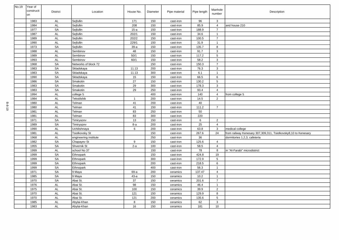
1983 AL Sejfullin 171 150 cast-iron 96 31984 AL Sejfullin 208 150 cast-iron 85.9 4 and house 2101977 SA Sejfullin 15-a 150 cast-iron 188.9 71987 AL Sejfullin 202/1 150 cast-iron 34.6 11989 AL Sejfullin 202/2 150 cast-iron 100.5 71990 AL Sejfullin 229/1 150 cast-iron 31.9 11973 SA Sejfullin 39-a 150 cast-iron 135.7 81988 AL Sembinov 48 150 cast-iron 91.7 31989 AL Sembinov 50/1 150 cast-iron 117.2 51993 AL Sembinov 60/1 150 cast-iron 58.2 31968 SA Networks of block 72 150 cast-iron 150.3 71983 SA Skladskaya 11.13 200 cast-iron 76.3 31983 SA Skladskaya 11.13 300 cast-iron 6.1 11990 SA Skladskaya 15 150 cast-iron 66.5 61986 SA Smakotin 27 150 cast-iron 130.2 51983 SA Smakotin 29 300 cast-iron 178.3 31983 SA Smakotin 29 250 cast-iron 93.4 41994 AL college 5 400 cast-iron 140 4 from college 51984 AL Tekstilshik 1 200 cast-iron 14.5 21980 AL Telman 41 200 cast-iron 401980 AL Telman 41 150 cast-iron 111.2 71981 AL Telman 83 250 cast-iron 501981 AL Telman 83 300 cast-iron 2201971 SA Timiryazev 13 150 cast-iron 6 21989 SA Timiryazev 8-a 200 cast-iron 25 41990 AL Uchilishnaya 6 200 cast-iron 63.8 3 medical college1981 AL Tsiolkovsky St 150 cast-iron 267.6 24 from railway Kenesary 307,309,311, Tsiolkovsky8,10 to Kenesary1968 AL engineering institute 250 cast-iron 36 dormitories 1,2,3, cafeteria1982 SA Chapayev St 9 150 cast-iron 125.6 41955 SA Shvernik St 2-a 100 cast-iron 58.5 41999 AL school No 37 150 cast-iron 78 8 in "Al-Farabi" microdistrict1999 SA Ethnopark 150 cast-iron 424.8 191999 SA Ethnopark 300 cast-iron 172.9 51999 SA Ethnopark 200 cast-iron 218.5 61999 SA Ethnopark 400 cast-iron 56.3 11971 SA 9 Maya 69-a 200 ceramics 137.47 41985 SA 9 Maya 43-a 150 ceramics 10.2 11970 SA Abai St. 37 150 ceramics 201.6 71976 AL Abai St. 98 150 ceramics 46.4 11975 AL Abai St. 100 150 ceramics 39.9 21970 AL Abai St. 121 150 ceramics 129.9 81970 AL Abai St. 121 200 ceramics 135.6 51985 AL Abylai-Khan 8 150 ceramics 62 31983 AL Abylai-Khan 16 150 ceramics 181 10
B-8-19
Manholenumber Description
No.19 Year ofconstruction
District Location House No. Diameter Pipe material Pipe length

1983 AL Abylai-Khan 22 300 ceramics 46 21983 AL Abylai-Khan 22 200 ceramics 236 81986 AL Abylai-Khan 25/2. 150 ceramics 32.9 51986 AL Abylai-Khan 27/1. 200 ceramics 102.4 51986 AL Abylai-Khan 27/1. 300 ceramics 68.3 21986 AL Abylai-Khan 27/1. 150 ceramics 101.3 31985 AL Abylai-Khan 31/1. 150 ceramics 99.2 51969 SA Avtomatika 150 ceramics 513 23 settlement area sewerage1980 SA Auezov St 41 200 ceramics 72.2 71954 SA Auezov St 121 200 ceramics 315 13 Auezov St 121, 1231973 SA Auezov St 36 150 ceramics 87 61970 SA Auezov St 91 150 ceramics 74.9 21967 SA Auezov St 92 150 ceramics 85.3 31953 SA Begeldinov St 57 150 ceramics 56.6 21961 SA Begeldinov St 45 150 ceramics 90 21972 SA Begeldinov St 20-a 150 ceramics 29.1 11988 SA Belyakov St 30 150 ceramics 166 71980 SA Bogembai 19-a 150 ceramics 73.93 31980 SA Bogembai 7/1. 250 ceramics 48.4 3 Bogembai 9/2, 5/1, 3/11975 AL Ualihanov 4 150 ceramics 1171978 AL Ualihanov 6 150 ceramics 75.8 41981 AL Ualihanov 67 200 ceramics 262.81975 AL Ualihanov 74 150 ceramics 133.8 8 Abai St 1231970 SA Vokzalnaya 3 150 ceramics 96.5 61973 SA Vokzalnaya 5 150 ceramics 73.7 51989 AL Gabdulin 250 ceramics 772.3 16 from Omarov St1989 AL Gabdulin 300 ceramics 283.9 10 from Omarov St1966 SA Gete 4 150 ceramics 217.6 111968 SA Gete 10 150 ceramics 136.6 91978 SA Gete 4-a 200 ceramics 168.4 81997 SA Kindergarden No 51 150 ceramics 226.8 13 Respubliki 15/11984 SA Kindergarden No 66 150 ceramics 98.1 5 Pobeda 69-a1986 AL Kindergarden No 8 150 ceramics 174 8 microdistrict 31982 SA Delagatskaya St 62 200 ceramics 247.3 91978 SA Zhangildin 12 200 ceramics 68 11965 SA Zhangildin 14 150 ceramics 71 51962 SA Zhangildin 16 150 ceramics 85 51978 SA Zhangildin 25 250 ceramics 671975 SA Zhangildin 4-a 150 ceramics 301977 SA Druzhba 1 150 ceramics 601977 SA Druzhba 1 200 ceramics 1651968 SA Druzhba 13 200 ceramics 133.3 81980 SA Druzhba 26.28 150 ceramics 65.6 81980 SA Druzhba 52 150 ceramics 51.4 3
B-8-20
Manholenumber Description
No.20 Year ofconstruction
District Location House No. Diameter Pipe material Pipe length

1984 SA Druzhba 54 150 ceramics 69.7 81982 SA Druzhba 52-a 200 ceramics 18.4 11982 SA Druzhba 52-a 150 ceramics 63 41963 AL Kindergarden No 12 150 ceramics 83.5 5 Lomonosov 521984 SA Dulatov 182 150 ceramics 80.6 41980 AL DUOD 200 ceramics 163.7 61980 AL DUOD 150 ceramics 212.2 61978 SA Kazakhskaya 50 150 ceramics 61.5 41989 SA Kazakhskaya 83 200 ceramics 11.8 21980 SA Kazakhskaya 66-a 300 ceramics 102.8 41951 SA Kenesary 68 150 ceramics 38 51954 SA Kenesary 72 150 ceramics 62.7 61997 AL Kenesary 103 150 ceramics 80 21963 AL Kenesary 208 200 ceramics 56.3 31999 SA Kenesary 200 ceramics 117 4 health-rehabilitating centre1963 SA Sewer collector No 6 300 ceramics 882 from VRZ to pump station No 21959 SA Constitution St 13.11 100 ceramics 95 71987 SA Constitution St 25 150 ceramics 108.8 41959 SA Constitution St 2-b 150 ceramics 33 4 Constitution 2-b, 6-a, 8-a1989 AL Kr. Krest St 76 150 ceramics 97.3 71989 AL Kr. Krest St 76 200 ceramics 39.9 31989 AL Kr. Krest St 721 200 ceramics 57.7 11989 AL Kr. Krest St 72/1 150 ceramics 69.8 11985 SA Krivoguz St 9.11 150 ceramics 195.5 71980 AL Kujbyshev St 71 150 ceramics 89.51990 AL Likhachev 11 200 ceramics 137 41988 AL Lomonosov St 57 200 ceramics 185 8 Sembinov 48/1, 48/21991 AL Manas 14/6. 150 ceramics 44.6 21990 AL "Alatau" microdistrict 2 150 ceramics 237 81975 AL "Alatau" microdistrict 12 200 ceramics 581975 AL microdistrict 1 1.2 200 ceramics 201.21975 AL microdistrict 1 3 150 ceramics 1521975 AL microdistrict 1 4 150 ceramics 1431969 AL microdistrict 1 12 200 ceramics 95.9 71981 AL microdistrict 1 13 200 ceramics 114.41975 AL microdistrict 1 14 125 ceramics 132.81981 AL microdistrict 1 15 150 ceramics 6.61977 AL microdistrict 1 16 200 ceramics 681974 AL microdistrict 1 17 200 ceramics 129.4 71978 AL microdistrict 1 20 150 ceramics 277.31978 AL microdistrict 1 21 150 ceramics 218.21981 AL microdistrict 1 28 150 ceramics 71.4 51975 AL microdistrict 2 2 200 ceramics 581975 AL microdistrict 2 2 150 ceramics 126.1
B-8-21
Manholenumber Description
No.21 Year ofconstruction
District Location House No. Diameter Pipe material Pipe length

1975 AL microdistrict 2 4 150 ceramics 851975 AL microdistrict 2 6.7 150 ceramics 2691975 AL microdistrict 2 10 150 ceramics 66.31975 AL microdistrict 2 11 150 ceramics 1041978 AL microdistrict 2 16 150 ceramics 23.21977 AL microdistrict 2 17 150 ceramics 31.81980 AL microdistrict 2 20 150 ceramics 128.3 61975 AL microdistrict 2 29 150 ceramics 210.81975 AL microdistrict 2 - microdistrict 4 300 ceramics 300 between microdistricts 2 and 41993 AL microdistrict 2-a 8 250 ceramics 114.2 51993 AL microdistrict 2-a 8 300 ceramics 73.3 21986 AL microdistrict 3 6 300 ceramics 528.3 201986 AL microdistrict 3 10 200 ceramics 68.3 61989 AL microdistrict 4 16 150 ceramics 71.9 21989 AL microdistrict 4 16 200 ceramics 51.5 31982 AL microdistrict 4 20 300 ceramics 178.8 71985 AL microdistrict 4 21 200 ceramics 190.4 71986 AL microdistrict 4 24 200 ceramics 111.6 51985 AL microdistrict 4 27 150 ceramics 69 31985 AL microdistrict 4 27 200 ceramics 97.7 41983 AL microdistrict 4 31 150 ceramics 106.8 81983 AL microdistrict 4 31 200 ceramics 206.1 51992 AL microdistrict 4 35 150 ceramics 21.4 91988 AL microdistrict 5 5 150 ceramics 102.8 61988 AL microdistrict 5 13 150 ceramics 75.1 41989 AL microdistrict 5 17 200 ceramics 106.8 41989 AL microdistrict 5 17 150 ceramics 78 21969 AL "Alatau" microdistrict 1 200 ceramics 74 51969 AL "Alatau" microdistrict 4 150 ceramics 92 61969 AL "Alatau" microdistrict 6,8,10 150 ceramics 310.1 151981 AL "Molodezhny" microdistrict 5 200 ceramics 135 61980 AL "Molodezhny" microdistrict 7 200 ceramics 266.35 17 houses 7,7-a,8,9,9-a1980 AL "Molodezhny" microdistrict 10 150 ceramics 100 51980 AL "Molodezhny" microdistrict 13 150 ceramics 88 51983 AL "Molodezhny" microdistrict 27 150 ceramics 69.5 41983 AL "Molodezhny" microdistrict 33 150 ceramics 48.3 41981 AL "Molodezhny" microdistrict 34 150 ceramics 163 71982 AL "Molodezhny" microdistrict 35 200 ceramics 80 31983 AL "Molodezhny" microdistrict 36 150 ceramics 108 51982 AL "Molodezhny" microdistrict 37 150 ceramics 137.4 61985 AL "Molodezhny" microdistrict 38 200 ceramics 42.2 11985 AL "Molodezhny" microdistrict 42 150 ceramics 101.6 41983 AL "Molodezhny" microdistrict 43 150 ceramics 76.5 41983 AL "Molodezhny" microdistrict 43 200 ceramics 68.2 1
B-8-22
Manholenumber Description
No.22 Year ofconstruction
District Location House No. Diameter Pipe material Pipe length

1984 AL "Molodezhny" microdistrict 44 150 ceramics 112.4 61988 AL Mozhajsky St 5-a 150 ceramics 200 121955 SA Monin St 15 150 ceramics 123.6 71957 SA Monin St 17 200 ceramics 302.8 20 Monin St 17,19,211957 SA Moskovskaya St 50 150 ceramics 90 91957 SA Moskovskaya St 50 300 ceramics 141.2 21964 SA Moskovskaya St 62.54 150 ceramics 202.5 21964 SA Moskovskaya St 62.54 200 ceramics 177.2 11967 SA Moskovskaya St 82 200 ceramics 63.9 51983 AL Naberezhnaya St 46 150 ceramics 165.3 91969 SA Pressure sewer collector 250 ceramics 1200 2 from wastewater pump station 28 "Avtomatika" village1969 SA Omarov St 53 150 ceramics 134.3 61981 AL Cancer hospital 200 ceramics 66.5 101970 AL Otyrar St 69 150 ceramics 5.8 11985 SA Pervomajskaya St 8 150 ceramics 85 51961 SA Pionerskaya St 13 150 ceramics 42.4 31982 SA Pionerskaya St 31 200 ceramics 67 41980 SA Pobeda 12 150 ceramics 42.5 31981 SA Pobeda 65/3 150 ceramics 81.61981 SA Pobeda 65/3 300 ceramics 52.41963 SA Pobeda 200 ceramics 877 20 from the corner of Moskovskaya to "Malaya" pump station1982 AL Polevaya 2 150 ceramics 51.1 31980 AL Polevaya 150 ceramics 159 121971 AL Polevaya 150 ceramics 96 4 to KaragandaGIIZ1972 SA Potanin St 6 150 ceramics 32.4 71976 SA Potanin St 20-a 150 ceramics 90.51965 AL Promyshlenny 150 ceramics 1888.9 621982 SA Pushkin St 171 200 ceramics 23 21982 SA Pushkin St 171-a 200 ceramics 48 11987 SA Pushkin St 97/1 200 ceramics 92.4 31987 SA Pushkin St 97/1 150 ceramics 46.8 21978 AL Respubliki 4 200 ceramics 97.31978 AL Respubliki 4 150 ceramics 6.41983 AL Respubliki 6 150 ceramics 65.8 51977 AL Respubliki 14 150 ceramics 60.9 41977 AL Respubliki 14 200 ceramics 86.3 51979 SA Respubliki 19 150 ceramics 341979 AL Respubliki 16/1. 150 ceramics 115 51979 AL Respubliki 16/1. 150 ceramics 16 11980 SA Respubliki 3/1. 150 ceramics 97.5 81982 AL Respubliki 4-b 150 ceramics 42.5 21979 SA Respubliki 5/1. 200 ceramics 34.21976 AL Rechnaya 40-a 150 ceramics 1001974 SA Sejfullin 32 150 ceramics 62
B-8-23
Manholenumber Description
No.23 Year ofconstruction
District Location House No. Diameter Pipe material Pipe length

1989 AL Sembinov 61 250 ceramics 256.5 51968 SA Networks of block 72 150 ceramics 852.1 421988 AL Smakotin 94 150 ceramics 491969 AL Smakotin 107 150 ceramics 279 81973 AL Sorokovaya 400 ceramics 1520 38 from Sorokovaya station to "Al-Farabi" microdistrict1973 AL Sorokovaya 600 ceramics 2076.6 57 from Sorokovaya station to "Al-Farabi" microdistrict1984 AL Stroitelej St 1/1. 200 ceramics 219.4 71986 AL Stroitelnaya St 1 150 ceramics 308.9 101986 AL Stroitelnaya St 1 200 ceramics 147 101984 AL Tekstilshik 1 150 ceramics 48.1 11984 AL Tekstilshik 1 200 ceramics 84.9 21978 AL Telman 83 150 ceramics 105 111981 AL Telman 83 200 ceramics 451967 SA Shvernik St 1 150 ceramics 123.8 51966 SA school No 23 200 ceramics 366.5 12 Kurskaya 171969 AL school No 28 150 ceramics 191.5 6 microdistrict 11969 AL school No 28 200 ceramics 109.9 4 microdistrict 11976 AL school No 31 200 ceramics 313.2 12 Kenesary 1391970 AL Zagorodnyy samotechny c-r 1500 ferroconcrete 6300 second sewerage zone1965 SA Zagorodnyy samotechny c-r 1500 ferroconcrete 2221 from the "Avarijnaya" manhole to the pump station 61970 AL Sewer collector No 1 1000 ferroconcrete 1430 along Gastello Per. Asfaltovy to collector 101970 AL Sewer collector No 10 1000 ferroconcrete 600 from KK-67 to pump station No 73341970 AL Sewer collector No 10 1000 ferroconcrete 590 from PK-0 to PK 20+0481973 AL Sewer collector No 10 1000 ferroconcrete 1510 from PK-0 to PK -20+40.61971 AL Sewer collector No 11 800 ferroconcrete 740 from the engineering institute1971 AL Sewer collector No 11 800 ferroconcrete 800 from the engineering institute1973 AL Sewer collector No 11 700 ferroconcrete 300 from PK-59 to PK-24 from the engineering institute1970 AL Sewer collector No 12 1000 ferroconcrete 855.5 67 from KK-1 to KK 671973 AL Sewer collector No 12 700 ferroconcrete 26951964 SA Sewer collector No 2 700 800 ferroconcrete 3176 Imanov, Bukejhan, Krasnoarmejskaya, Delegatskaya, Kulturnaya1975 SA Sewer collector No 5 600 ferroconcrete 1474 from Delegatskaya to Rabochaya (from the hoisting unit)1974 SA Sewer collector No 6 800 ferroconcrete 311 along Pervomajskaya to Constitution St1974 SA Sewer collector No 6 800 ferroconcrete 430 from Constitution by Rabochaya, Novaya, Orenbur to PS No 31974 SA Sewer collector No 6 1000 ferroconcrete 1555 from Constitution by Rabochaya, Novaya, Orenbur to PS No 41988 AL Lomonosov St 56 200 ferroconcrete 62.2 41998 SA Pressure sewer collector 800 ferroconcrete 1620 from pump station 1-A1999 SA Pressure sewer collector 800 ferroconcrete 660 syphon transition from wastwater pump station 61974 SA Pushkin St 500 ferroconcrete 3661974 SA Pushkin St 300 ferroconcrete 2341987 AL Abylai-Khan 3 150 polyethylene 113 71998 SA Pressure sewer collector 100 polyethylene 827 7 sports complex on the left riverbank1999 SA Pressure sewer collector 150 polyethylene 1300 3 from wastwater pump station of the Reception House1990 SA Abai St. 1 150 steel 66.9 51990 SA Abai St. 1 200 steel 189.7 8
B-8-24
Manholenumber Description
No.24 Year ofconstruction
District Location House No. Diameter Pipe material Pipe length

1969 SA Avtomatika 100 steel 1262.5 42 settlement area sewerage1994 AL Engineering Institute (AISI) 300 steel 100 31965 AL Alluvij 100 steel 73.2 area-internal networks1981 SA Pressure sewer collector 600 steel 600 from pump station 1 to the sewer of zone11970 SA Pressure sewer collector 0 600 steel 3200 12 pressure collector from pump station 6 to sewer of zone 11964 AL Pressure sewer collector 0 300 steel 400 3 pressure sewer from pump st 214 by cemetery, by Zhukovsky1965 SA Pressure sewer collector 400 steel 1670 from pump station 1 to "Avarijnaya" manhole1964 SA Pressure sewer collector 400 steel 2285 from pump station 2 to "Avarijnaya" manhole1965 SA Pressure sewer collector 400 steel 1985 from pump station 1 to "Avarijnaya" manhole1965 SA Pressure sewer collector 400 steel 2512 from pump station 9 to "Avarijnaya" manhole1964 SA Pressure sewer collector 400 steel 2512 from pump station 9 to "Avarijnaya" manhole1970 AL Pressure sewer collector 600 steel 2900 from pump station 7 - 2nd sewerage zone with syphon1965 AL Pressure sewer collector 200 steel 1200 pump station 214 to Imanov St. (sewer 2)1963 SA Pressure sewer collector 200 steel 118 from pump station VRZ to sewer 61963 SA Pressure sewer collector 350 steel 1100 from pump station VRZ to sewer 61974 SA Pressure sewer collector 400 steel 147 two lines from pump station 3 to suburban sewer of zone 11981 SA Pressure sewer collector 700 steel 1460 from pump station 1 to the sewer of zone11993 SA Pressure sewer collector 500 steel 1100 from pump station 3 to pump station 61984 SA Pressure sewer collector 100 steel 1051.5 from pump station (in Skladskaya St) to ceramic plant sewer1986 SA Pressure sewer collector 150 steel 1036 2 from "Kazahtranstehmontazh" pump station to the manhole1998 SA Pressure sewer collector 700 steel 102 from pump station 1-A1999 AL Pressure sewer collector 325 steel 1380 from wastewater pump station 30 "Al-Farabi" microdistrict1999 AL Pressure sewer collector 500 steel 370 5 from wastewater pump station 30 "Al-Farabi" microdistrict1999 SA Pressure sewer collector 200 steel 384 3 from wastwater pump station of Ethnopark - two lines1999 SA Pressure sewer collector 900 steel 390 2 syphon transition from wastwater pump station 61966 SA Pressure sewer collector 400 steel 2670 from pump station 2 to "Avarijnaya" manhole1970 AL Imambayeva 7271997 AL microdistrict 2-a 1 inlets to the existing network1993 AL microdistrict 3 11 inlets to the existing network1998 AL Respubliki 22 inlets to the existing net1984 AL Respubliki 4/2. 2 inlet to the existing network with two manholes installment1989 AL Sembinov 48/3 1
5279
TOTAL LENGTH 226578.42asbestos-cement 45461.51cast-iron 85380.96ceramics 32574.45ferroconcrete 27929.7polyethylene 2240steel 32264.8other 727
B-8-25
Manholenumber Description
No.25 Year ofconstruction
District Location House No. Diameter Pipe material Pipe length
Appendix B-9
Site Confirmation of Siphon Structure and Culverts
at the Taldy Kol Reservoir
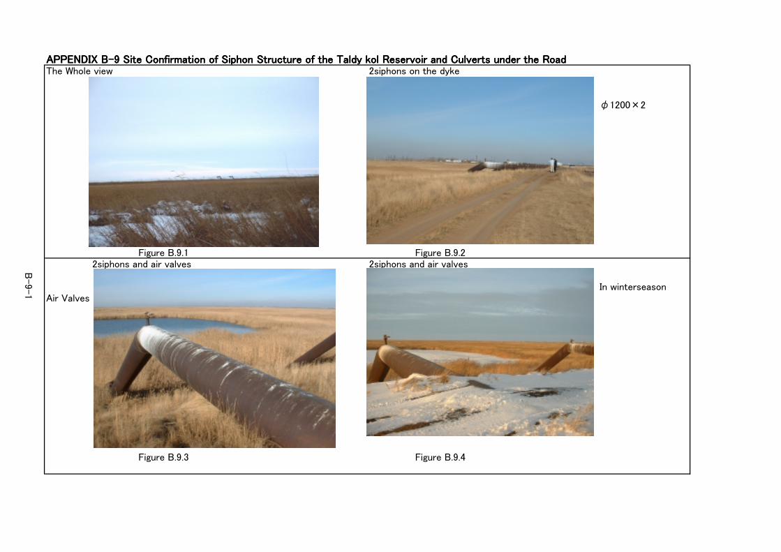
APPENDIX B-9 Site Confirmation of Siphon Structure of the Taldy kol Reservoir and Culverts under the RoadAPPENDIX B-9 Site Confirmation of Siphon Structure of the Taldy kol Reservoir and Culverts under the RoadAPPENDIX B-9 Site Confirmation of Siphon Structure of the Taldy kol Reservoir and Culverts under the RoadAPPENDIX B-9 Site Confirmation of Siphon Structure of the Taldy kol Reservoir and Culverts under the RoadThe Whole view 2siphons on the dyke
φ1200×2
Figure B.9.1 Figure B.9.22siphons and air valves 2siphons and air valves
In winterseasonAir Valves
Figure B.9.3 Figure B.9.4
B-9-1

Flap valve 2siphons into Taldykol
Figure B.9.5 Figure B.9.62culvert under the road 7culvert under the road
φ1200×2 φ800×7
Figure B.9.7 Figure B.9.8
B-9-2

Appendix B-10
Examination of Sludge Dewatering Process

Detailed Design Study on Water Supply and Sewerage System for Astana City Final Report
B-10-1
APPENDIX B-10 Examination of Sludge Dewatering Process
B.10.1 Object
1) To clarify the most suitable dewatering unit for the STP
2) To compare the advantage and disadvantage between Screw Press and Filter Press
B.10.2 Condition of examination
1) Sludge volume is the same with main report. Characteristic of the sludge is digested sludge.
・Dry Solids=16.452 t/day ・Sludge Volume=548 m3/day ・Sludge Concentration=3.0%
2) Operation time is as follows:
(1) Screw Press 24 hours/day, 7days/week (Continuous Operation)
(2) Filter Press 8hours/day, 6days/week (Consecutive Batch Operation during the working hours)
3) The specification and numbers of the dewatering machine is as follows:
(1) Screw Press 450kg/hr/unit, 3 units (100%) including 1 reserve
(2) Filter Press 150m2/unit, 12 units(400%) including 2 reserves
B.10.3 Examination
Items for this examination are advantage, disadvantage and construction cost as shown in Table
B.10.1. Advantage of Filter Press is limited only in water content of sludge that is 70%. On the
other hand, it has so much problem of size of the facility (200%), numbers of the equipment (400%),
numbers of the operation personnel (600%), and construction cost (170%). Filter press is not
recommendable from the viewpoint of technical, maintenance and cost.
Furthermore, the height of the building is 3m higher than that of screw press, maintenance points and
break down frequency are much more and odour problem is bigger.
Screw press type is using motor to rotate the screw inside the casing, however the rotation speed is
only 1~2 rpm that never cause vibration and noise. The capacity of the motor is very low (3.7kw).
B.10.1 Conclusion
Screw press type is strongly recommended.
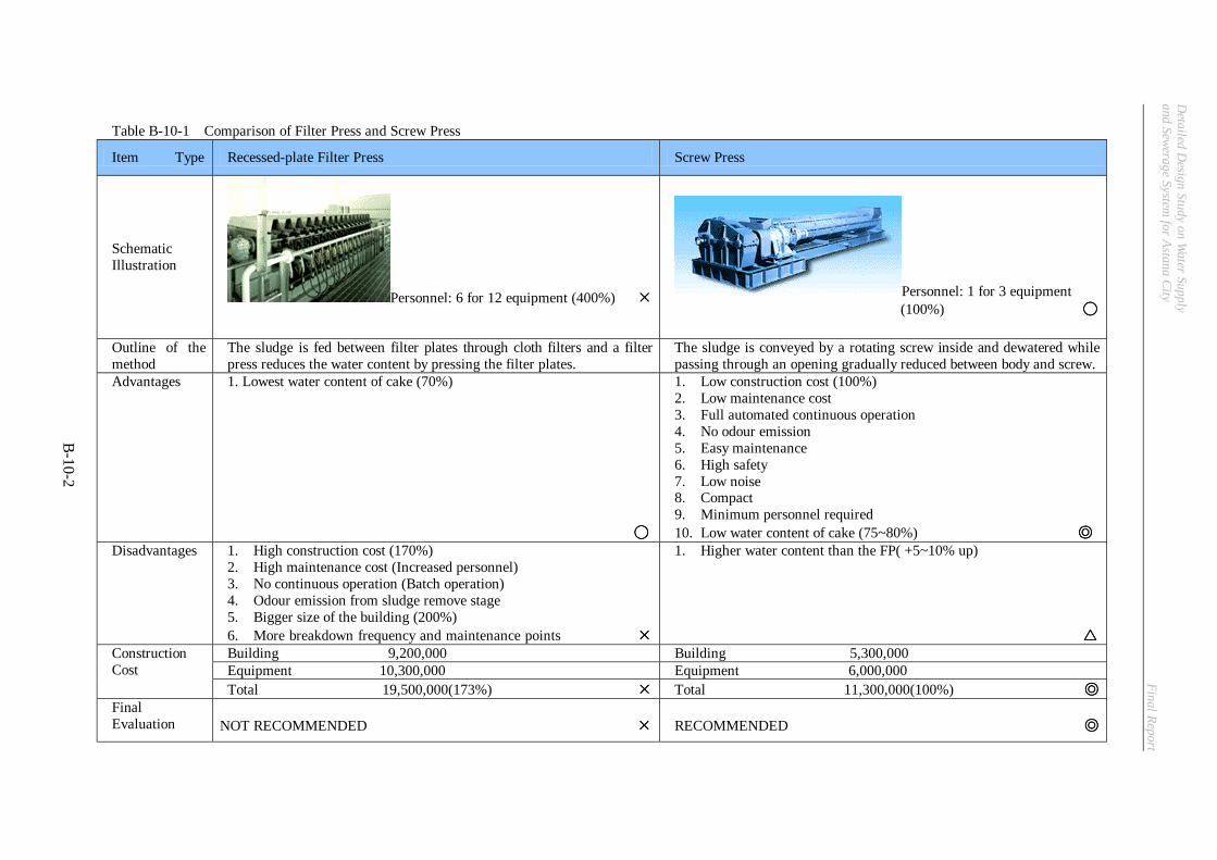
Detailed D
esign Study on Water Supply
and Sewerage System for Astana City
Final Report
B-10-2
Table B-10-1 Comparison of Filter Press and Screw Press
Item Type Recessed-plate Filter Press Screw Press
Schematic Illustration
Personnel: 6 for 12 equipment (400%) ×××× Personnel: 1 for 3 equipment (100%) ◯◯◯◯
Outline of the method
The sludge is fed between filter plates through cloth filters and a filter press reduces the water content by pressing the filter plates.
The sludge is conveyed by a rotating screw inside and dewatered while passing through an opening gradually reduced between body and screw.
Advantages 1. Lowest water content of cake (70%)
◯◯◯◯
1. Low construction cost (100%) 2. Low maintenance cost 3. Full automated continuous operation 4. No odour emission 5. Easy maintenance 6. High safety 7. Low noise 8. Compact 9. Minimum personnel required 10. Low water content of cake (75~80%) ◎◎◎◎
Disadvantages 1. High construction cost (170%) 2. High maintenance cost (Increased personnel) 3. No continuous operation (Batch operation) 4. Odour emission from sludge remove stage 5. Bigger size of the building (200%) 6. More breakdown frequency and maintenance points ××××
1. Higher water content than the FP( +5~10% up) △△△△
Building 9,200,000 Building 5,300,000 Equipment 10,300,000 Equipment 6,000,000
Construction Cost
Total 19,500,000(173%) ×××× Total 11,300,000(100%) ◎◎◎◎ Final Evaluation
NOT RECOMMENDED ××××
RECOMMENDED ◎◎◎◎