Embed Size (px)
Citation preview
The Regional Municipality of Niagara
APPENDIX B - BRIDGE INSPECTION REPORTS
• 2017 Bridge Inspection Report • 2018 Load Capacity Evaluation Report
B-1
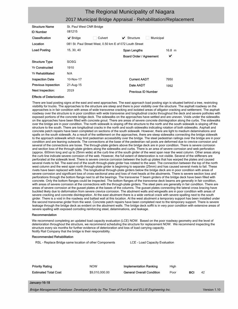
The Regional Municipality of Niagara 2017 Municipal Bridge Appraisal - Rehabilitation/Replacement
Structure Name St. Paul West CNR Bridge
ID Number 081215
Classification Bridge Culvert Structure Municipal
Location 081 St. Paul Street West, 0.50 km E of 072 Louth Street
Load Posting 15, 30, 40 Span Lengths 16.8 m
Board Order / Agreement
Structure Type SOSG
Yr Constructed 1910
Yr Rehabilitated N/A
Inspection Date 10-Nov-17 Current AADT 7950
Previous Inpsection 21-Aug-15 Date AADT 1992 Next Inspection: 2019 Previous ID Number
Effects of Deterioration
There are load posting signs at the east and west approaches. The east approach load posting sign is situated behind a tree, restricting visibility for trucks. The approaches to the structure are steep and there is poor visibility over the structure. The asphalt roadway on the approaches is in fair condition with areas of wide transverse cracking and isolated areas of alligator cracking and settlement. The asphalt roadway over the structure is in poor condition with wide transverse and longitudinal cracks throughout the deck and severe potholes with exposed portions of the concrete bridge deck. The sidewalks on the approaches have settled and are uneven. Voids under the sidewalks on the approaches have been filled with concrete grout. There are areas of severe concrete disintegration along the curbs. The sidewalks over the bridge are in poor condition. The north sidewalk is sloping off the structure to the north and the south sidewalk is sloping off the structure to the south. There are longitudinal cracks in the north and south sidewalks indicating rotation of both sidewalks. Asphalt and concrete patch repairs have been completed on sections of the south sidewalk. However, there are light to medium delaminations and spalls on the south sidewalk. As a result of the settlement on the approaches, there are steep sidewalks connecting the bridge sidewalk to the approach sidewalk which may limit pedestrian accessibility over the bridge. The steel pedestrian railings over the bridge are in poor condition and are leaning outwards. The connections at the base of the pedestrian rail posts are deformed due to crevice corrosion and several of the connections are loose. The through-plate girders above the bridge deck are in poor condition. There is severe corrosion and section loss of the through-plate girders along the sidewalks and curbs. There is an area of severe corrosion and web perforation (approx. 600mm long and up to 25mm wide) at the curb line of the south girder of the west span near the west column. Other areas along the curb line indicate severe corrosion of the web. However, the full extent of deterioration is not visible. Several of the stiffeners are perforated at the sidewalk level. There is severe crevice corrosion between the built-up plates that has warped the plates and caused several rivets to fail. The east end of the south through-plate girder has rotated to the west. The connection between the top of the north west column and the west span north through-plate girder is beginning to separate (25mm) and has caused several rivets to fail. These rivets have been replaced with bolts. The longitudinal through-plate girders below the bridge deck are in poor condition with areas of severe corrosion and significant loss of cross-sectional area and loss of rivet heads at the abutments. There is severe section loss and perforations through the bottom flange next to all the bearings. The transverse 'I' beam girders of the bridge deck have been filled with concrete. Only the bottom flanges could be inspected. The bottom flanges of the transverse deck beams are generally in fair condition, with areas of severe corrosion at the connections with the through-plate girders. The steel piers are generally in fair condition. There are areas of severe corrosion at the gusset plates at the bases of the columns. The gusset plates connecting the lateral cross bracing have buckled likely due to deformation from severe crevice corrosion. The abutment walls and wingwalls are in poor condition with areas of severe cracking and concrete disintegration. At the east abutment there is a wide vertical crack with severe spalling next to the south girder. There is a void in the roadway and ballast wall at this location. At the west abutment a temporary support has been installed under the second transverse girder from the west. Concrete patch repairs have been completed next to the temporary support. There is severe leakage through the bridge deck as evident on the abutment walls. The bridge deck soffit is in very poor condition with extensive areas of severe spalling with exposed corroding reinforcing steel, delaminations, and leakage.
Recommendation
We recommend completing an updated load capacity evaluation (LCE) NOW. Based on the poor roadway geometry and the level of deterioration throughout the structure, we recommend scheduling the structure for replacement NOW. We recommend inspecting the structure every six months for further evidence of deterioration and loss of load carrying capacity. Notify Rail Company that the bridge is their responsibility.
Recommended Rehabilitation
RSL - Replace Bridge same location of other Components LCE - Load Capacity Evaluation
Priority Rating NOW Implementation Ranking High
Estimated Total Cost $9,010,000.00 General Overall Condition Poor BCI 42
January-16-18
Bridge Management Database: Developed jointly by The Town of Fort Erie and ELLIS Engineering Inc. Version 1.10
The Regional Municipality of Niagara 2017 Municipal Bridge Appraisal - Rehabilitation/Replacement
Structure Name St. Paul West CNR Bridge
ID Number 081215
Classification Bridge Culvert Structure Municipal
Location 081 St. Paul Street West, 0.50 km E of 072 Louth Street
Recommended Rehabilitation RSL - Replace Bridge same location of other Components LCE - Load Capacity Evaluation
Engineering Cost
Engineering $1,000,000.00
LCE $10,000.00
Sub Total $1,010,000.00
Construction Cost
RSL $8,000,000.00
$0.00
Sub Total
Total
$0.00
$0.00
$0.00
$8,000,000.00
$9,010,000.00
January-16-18
Bridge Management Database: Developed jointly by The Town of Fort Erie and ELLIS Engineering Inc. Version 1.10
The Regional Municipality of Niagara 2017 Municipal Bridge Appraisal - Rehabilitation/Replacement
St. Paul West CNR Bridge
081215
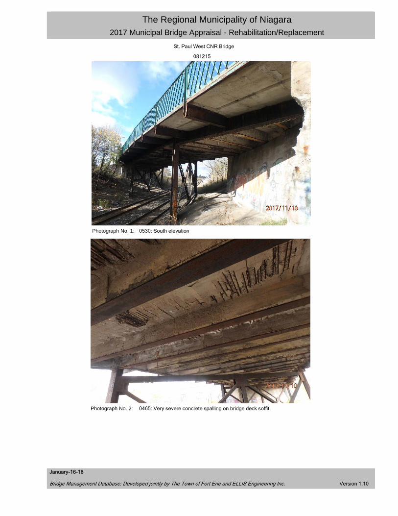
Photograph No. 1: 0530: South elevation
Photograph No. 2: 0465: Very severe concrete spalling on bridge deck soffit.
January-16-18
Bridge Management Database: Developed jointly by The Town of Fort Erie and ELLIS Engineering Inc. Version 1.10
The Regional Municipality of Niagara 2017 Municipal Bridge Appraisal - Rehabilitation/Replacement
St. Paul West CNR Bridge
081215
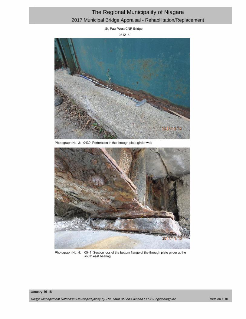
Photograph No. 3: 0430: Perforation in the through-plate girder web
Photograph No. 4: 0541: Section loss of the bottom flange of the through plate girder at the south east bearing
January-16-18
Bridge Management Database: Developed jointly by The Town of Fort Erie and ELLIS Engineering Inc. Version 1.10
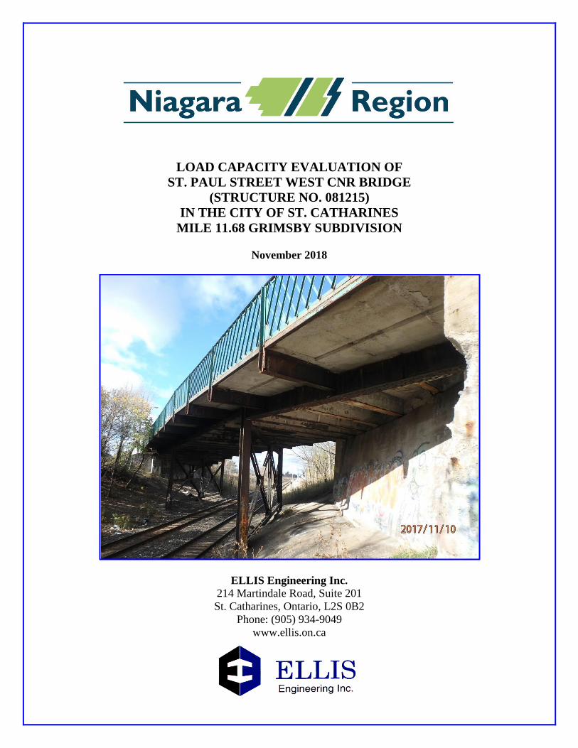
LOAD CAPACITY EVALUATION OF
ST. PAUL STREET WEST CNR BRIDGE
(STRUCTURE NO. 081215)
IN THE CITY OF ST. CATHARINES
MILE 11.68 GRIMSBY SUBDIVISION
November 2018
ELLIS Engineering Inc.
214 Martindale Road, Suite 201
St. Catharines, Ontario, L2S 0B2
Phone: (905) 934-9049
www.ellis.on.ca
THE REGIONAL MUNICIPALITY OF NIAGARA
LOAD CAPACITY EVALUATION OF
ST. PAUL STREET WEST CNR BRIDGE
(STRUCTURE NO. 081215)
IN THE CITY OF ST. CATHARINES
MILE 11.68 GRIMSBY SUBDIVISION
TABLE OF CONTENTS
Transmittal Letter ......................................................................................................................... i
Site Location – Key Plan .............................................................................................................. ii
Executive Summary ..................................................................................................................... iii
1. INTRODUCTION
1.1 Brief Description of the Bridge......................................................................................1
2. INSPECTION
2.1 Verification of Bridge Drawings ..................................................................................2
2.2 Effects of Deterioration..................................................................................................2
3. LOAD CAPACITY EVALUATION
3.1 Structural Evaluation ....................................................................................................4
3.1.1 Material Properties .........................................................................................4
3.1.2 Loads ..............................................................................................................5
3.1.3 Finite Element Analysis .................................................................................5
3.2 Structural Capacity.........................................................................................................6
3.3 Remaining Fatigue Life .................................................................................................8
4. CONCLUSION & RECOMMENDATIONS ..................................................................9
APPENDICES
Appendix ‘A’ Photographs (No. 1-6)
Appendix ‘B’ S-FRAME Finite Element Model Screenshots
Appendix ‘C’ Structural Steel Section Properties Report
Appendix ‘D’ 1922 Original Construction Drawings (13 Pages)
1977 Rehabilitation Drawings (5 Pages)
ELLIS Engineering Inc.
214 Martindale Road, Suite 201
St. Catharines, ON, L2S 0B2
Phone: (905) 934-9049
www.ellis.on.ca
November 23, 2018
The Regional Municipality of Niagara
1815 Sir Isaac Brock Way
Thorold, Ontario
L2V 4T7
Attention: Mr. Frank Tassone, C.E.T.
Associate Director, Transportation Engineering
Reference: Load Capacity Evaluation (LCE) for the St. Paul Street West CNR
Bridge, Region Structure No. 081215, Mile 11.68 Grimsby Subdivision.
Our File No.: 848.
We are pleased to submit a copy of the load capacity evaluation for the St. Paul Street West CNR
Bridge (Structure No. 081215), conducted in accordance with the Canadian Highway Bridge Design
Code (CHBDC CAN/CSA-S6-14). The report reviews the present condition of the existing three-
span concrete slab on steel girder bridge.
The primary task was to determine the load carrying capacity of the structure, in view of posting a
revised load limit. To accomplish this task, work included a visual inspection of the bridge to
confirm structural dimensions and the effects of deterioration, and a structural analysis using load
factors for evaluation. The conclusive results of the inspection and load capacity evaluation (LCE)
are included in this report.
We thank you for giving us the opportunity to provide our services for this project. Should you
have any questions concerning the report, please contact the undersigned.
Yours truly,
ELLIS Engineering Inc.
Duane VanGeest, P.Eng. Darryl Bakker, E.I.T.
ELLIS Engineering Inc. ELLIS Engineering Inc.
i

SITE LOCATION – KEY PLAN
St. Paul Street West CNR Bridge
Structure No. 081215
Mile 11.68 Grimsby Subdivision
ii
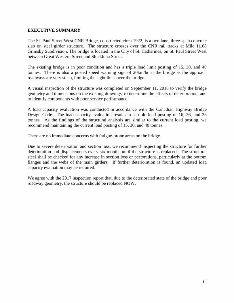
EXECUTIVE SUMMARY
The St. Paul Street West CNR Bridge, constructed circa 1922, is a two lane, three-span concrete
slab on steel girder structure. The structure crosses over the CNR rail tracks at Mile 11.68
Grimsby Subdivision. The bridge is located in the City of St. Catharines, on St. Paul Street West
between Great Western Street and Shickluna Street.
The existing bridge is in poor condition and has a triple load limit posting of 15, 30, and 40
tonnes. There is also a posted speed warning sign of 20km/hr at the bridge as the approach
roadways are very steep, limiting the sight lines over the bridge.
A visual inspection of the structure was completed on September 11, 2018 to verify the bridge
geometry and dimensions on the existing drawings, to determine the effects of deterioration, and
to identify components with poor service performance.
A load capacity evaluation was conducted in accordance with the Canadian Highway Bridge
Design Code. The load capacity evaluation results in a triple load posting of 16, 26, and 38
tonnes. As the findings of the structural analysis are similar to the current load posting, we
recommend maintaining the current load posting of 15, 30, and 40 tonnes.
There are no immediate concerns with fatigue-prone areas on the bridge.
Due to severe deterioration and section loss, we recommend inspecting the structure for further
deterioration and displacements every six months until the structure is replaced. The structural
steel shall be checked for any increase in section loss or perforations, particularly at the bottom
flanges and the webs of the main girders. If further deterioration is found, an updated load
capacity evaluation may be required.
We agree with the 2017 inspection report that, due to the deteriorated state of the bridge and poor
roadway geometry, the structure should be replaced NOW.
iii
1. INTRODUCTION
1.1 Brief Description of the Bridge
The existing concrete slab on steel girder structure was built circa 1922. The three-span, two lane
bridge spans over the CNR rail tracks at Mile 11.68 Grimsby Subdivision. The bridge is located on
St. Paul Street West between Great Western Street and Shickluna Street in the City of St.
Catharines.
The existing bridge is 13.9m wide and 41.5m long with span lengths of 14.8m, 17.4m, and 9.3m.
The superstructure consists of two longitudinal steel through-plate girders, supporting transverse
steel stringers, a reinforced concrete deck, and two reinforced concrete sidewalks. The transverse
steel stringers are encased in concrete. The substructure consists of concrete abutments and
structural steel piers. The bridge has a skew of approximately 51°.
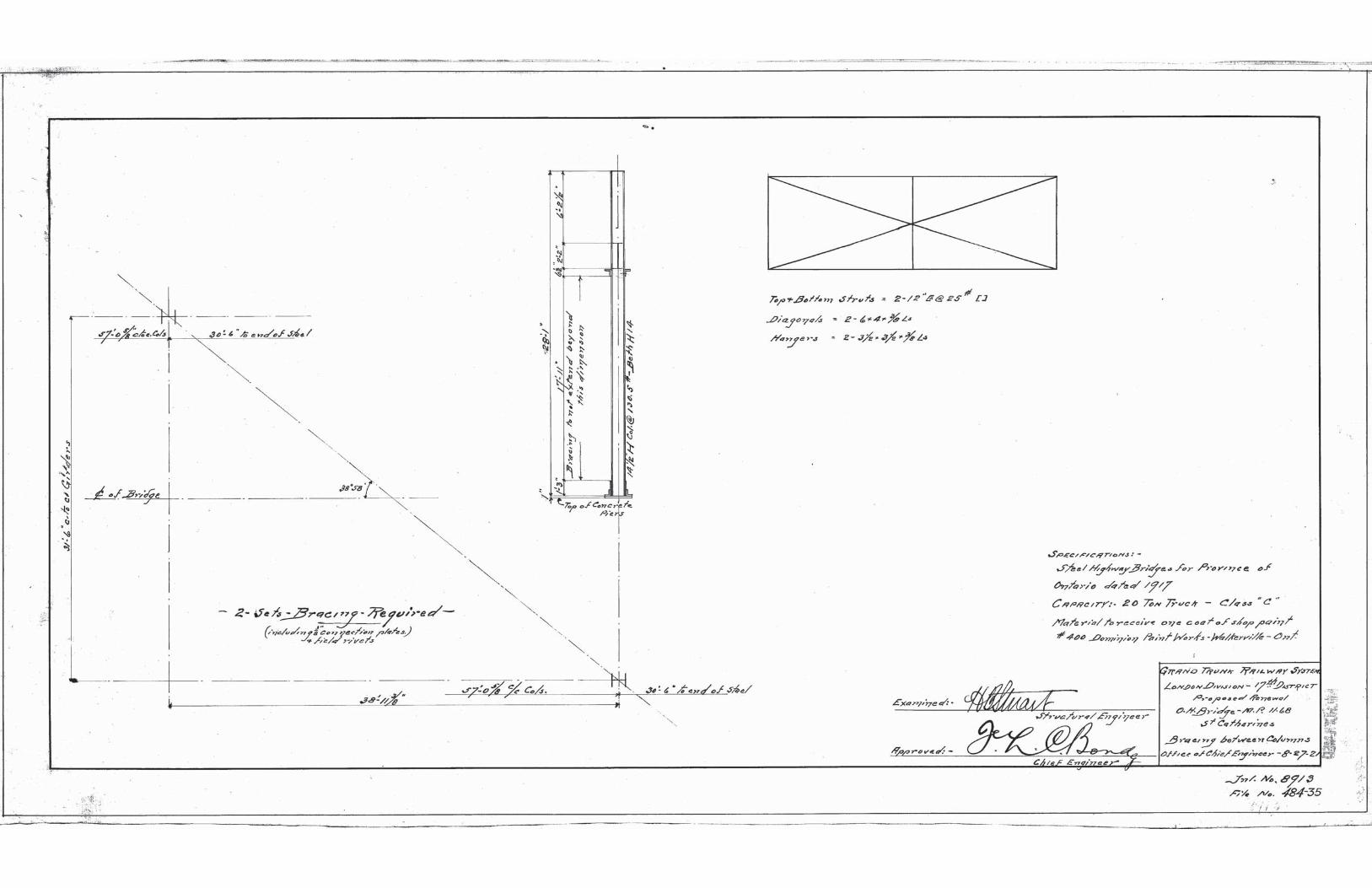
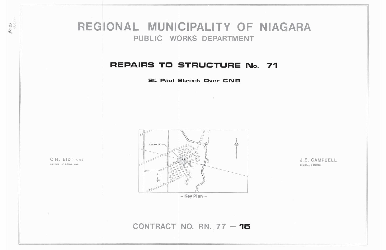
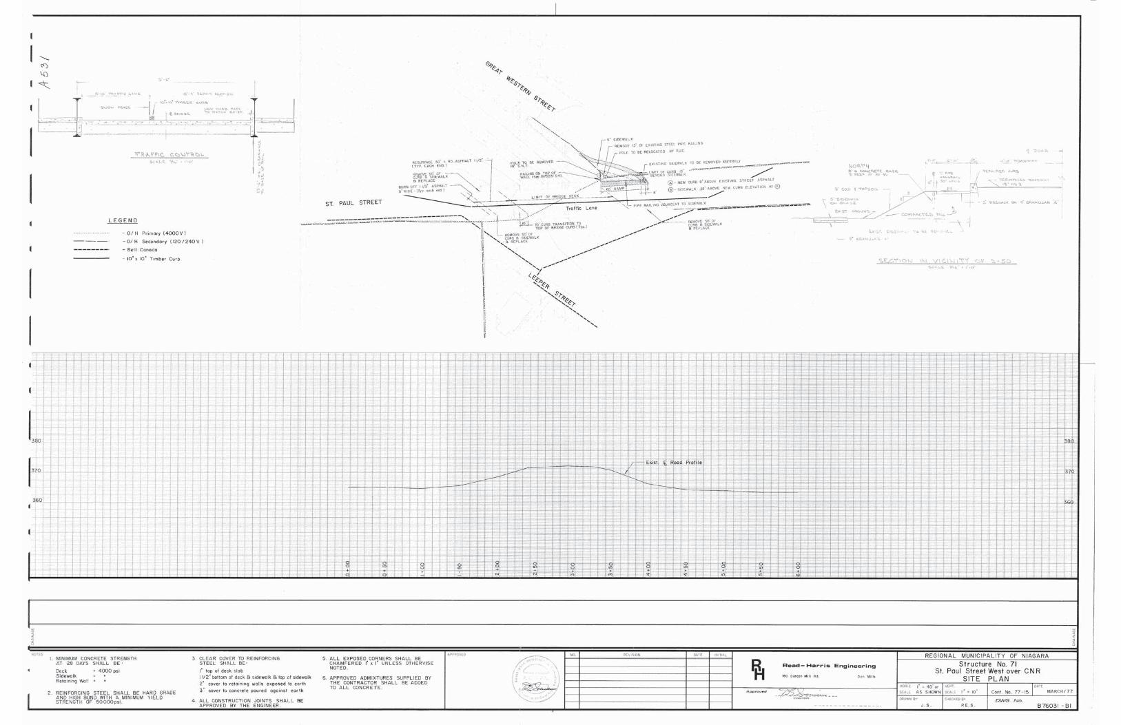
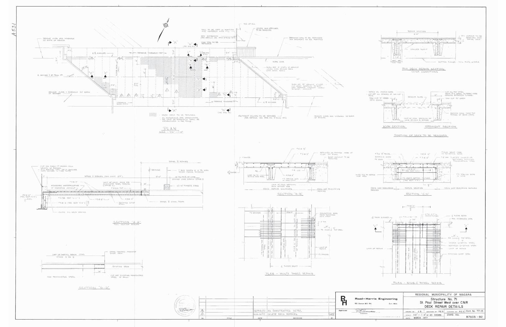
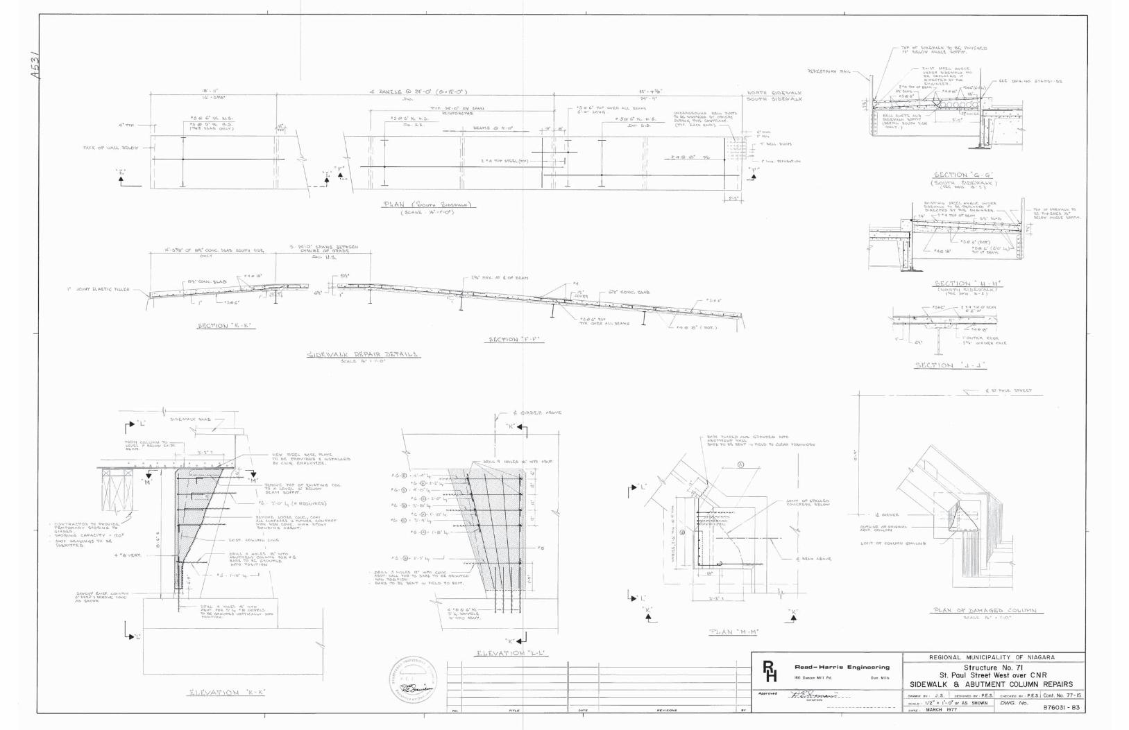
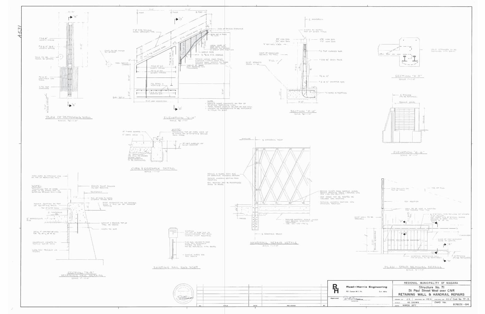
As per the 1977 rehabilitation drawings, work was done on the structure including:
Full depth replacement of portions of the reinforced concrete bridge deck;
Replacement of concrete on portions of the transverse stringers;
Replacement of both reinforced concrete sidewalks;
Repairs to the north end of the east abutment;
Waterproofing and asphalt paving;
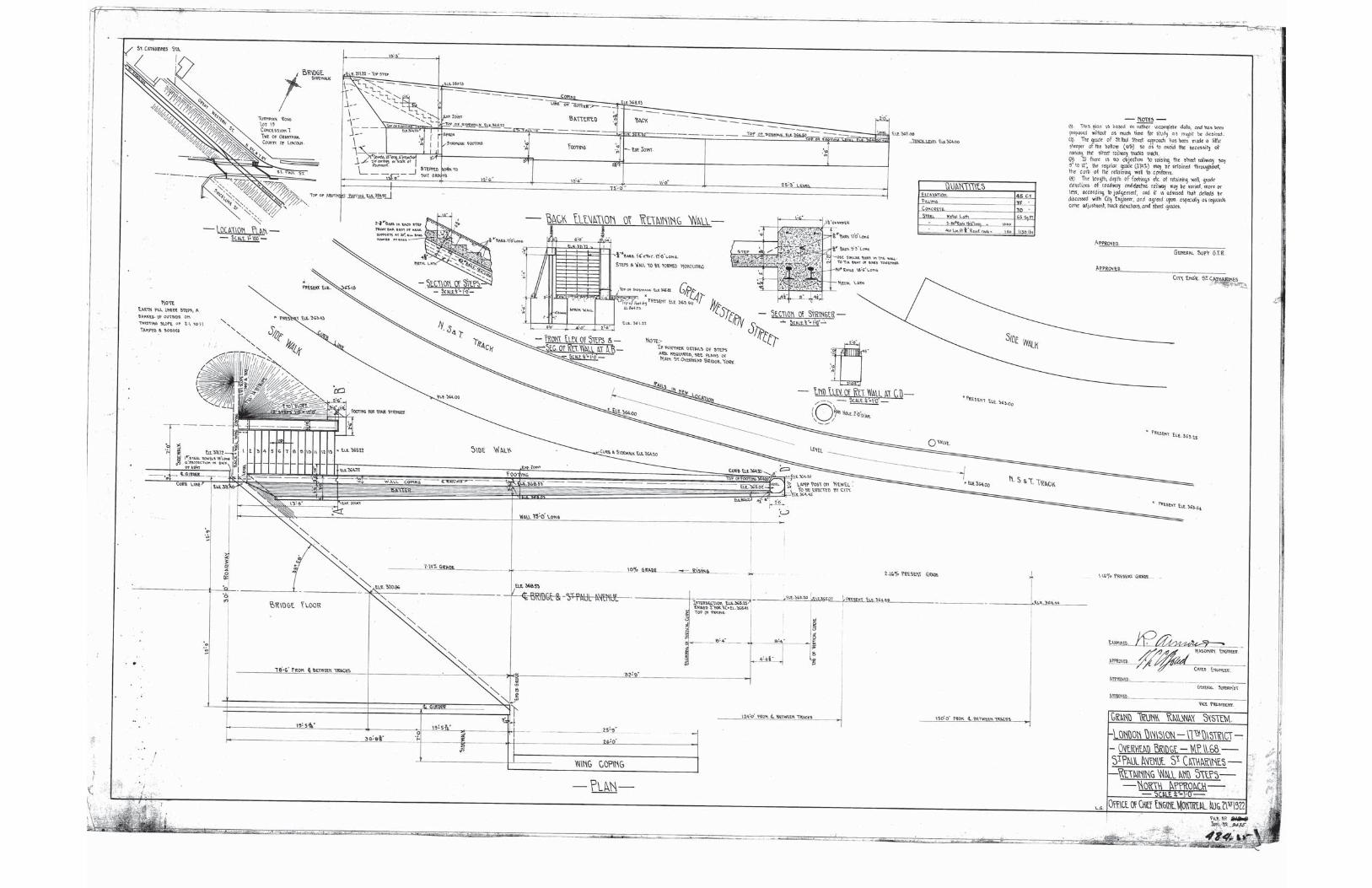
Removal of stairs and construction of a new reinforced concrete retaining wall at the
northwest corner.
In 2015, a temporary support was installed at the west abutment to support one of the transverse
stringers, where there was an area of severe concrete deterioration.
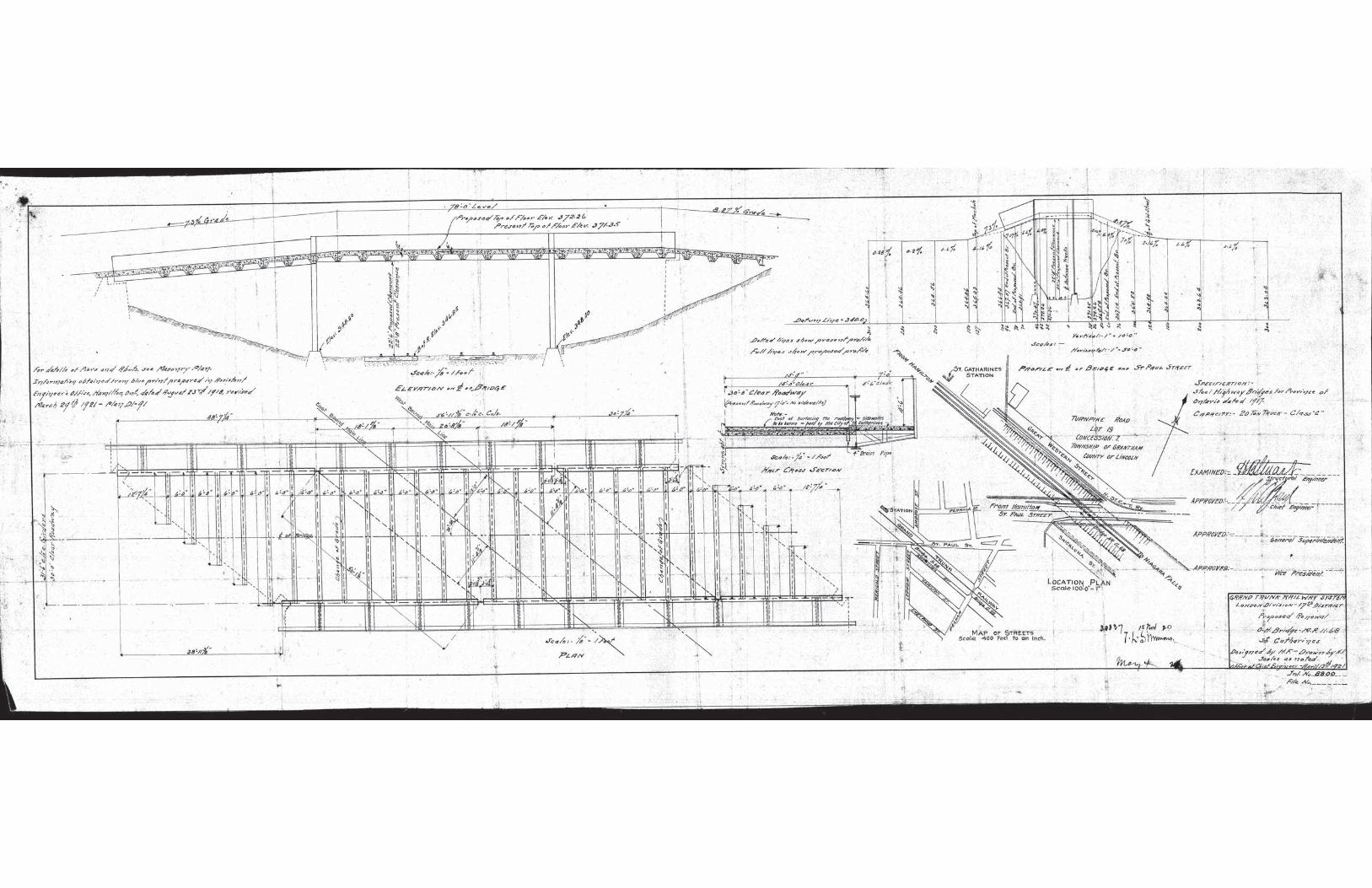
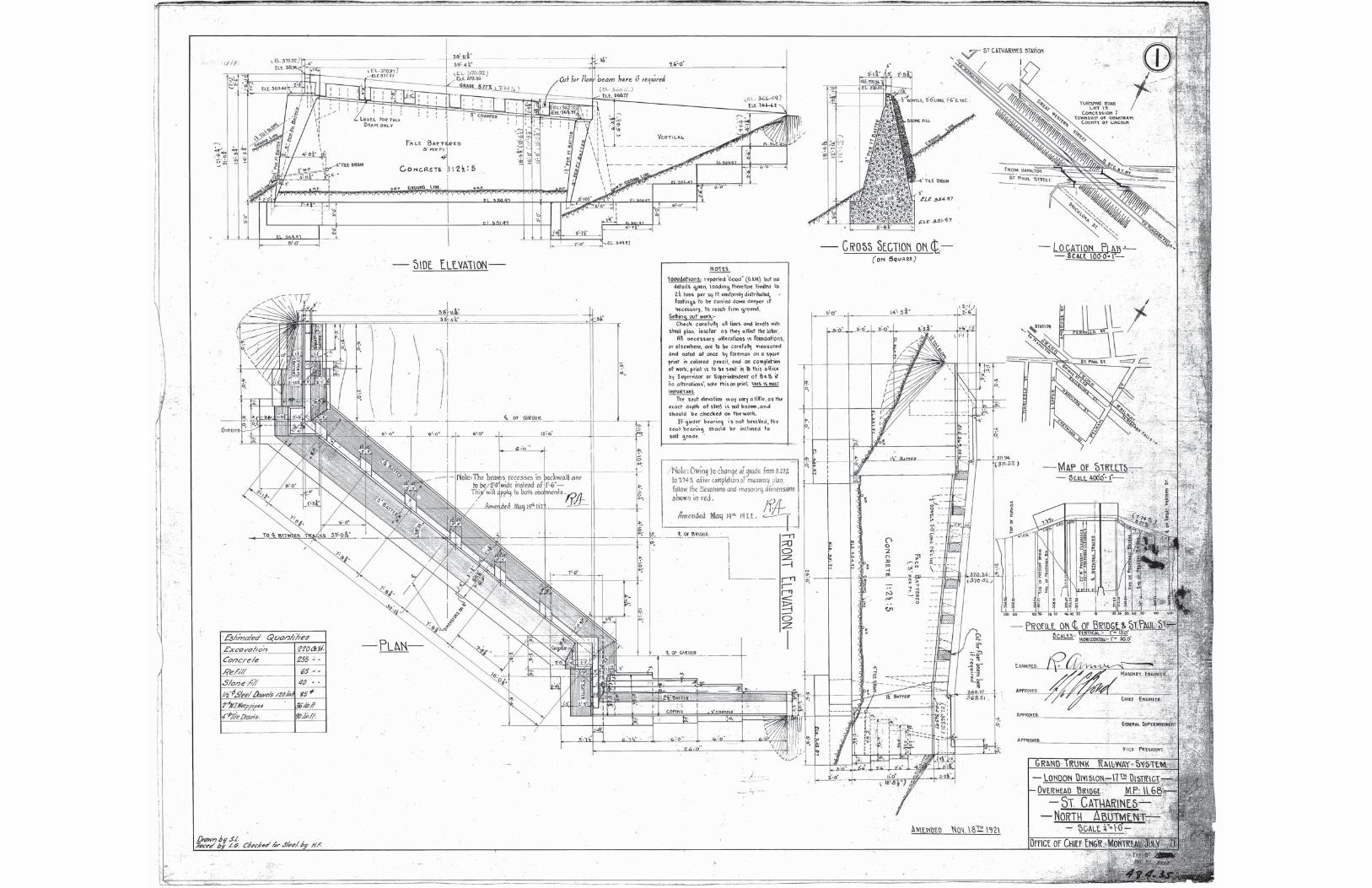
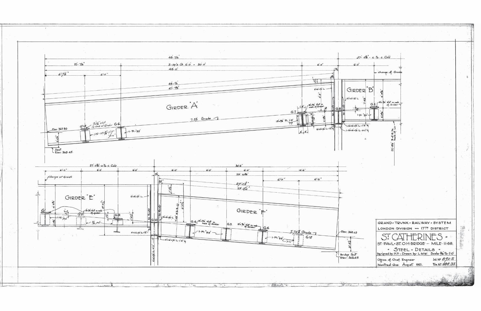
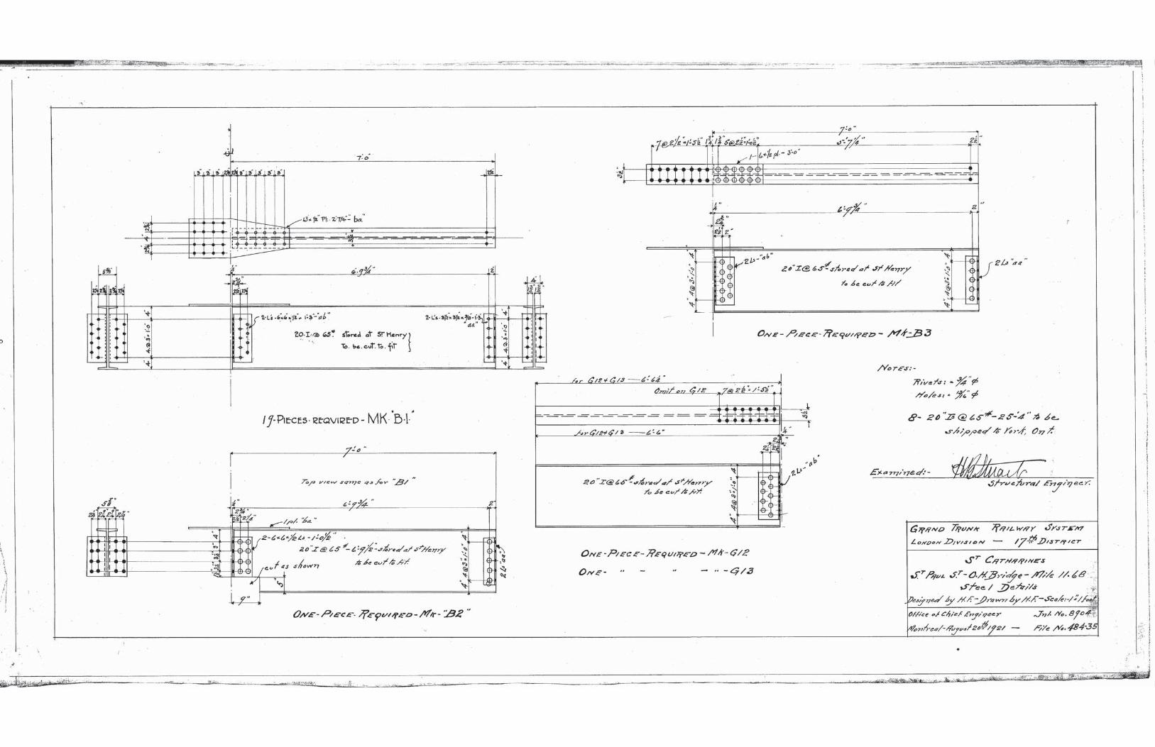
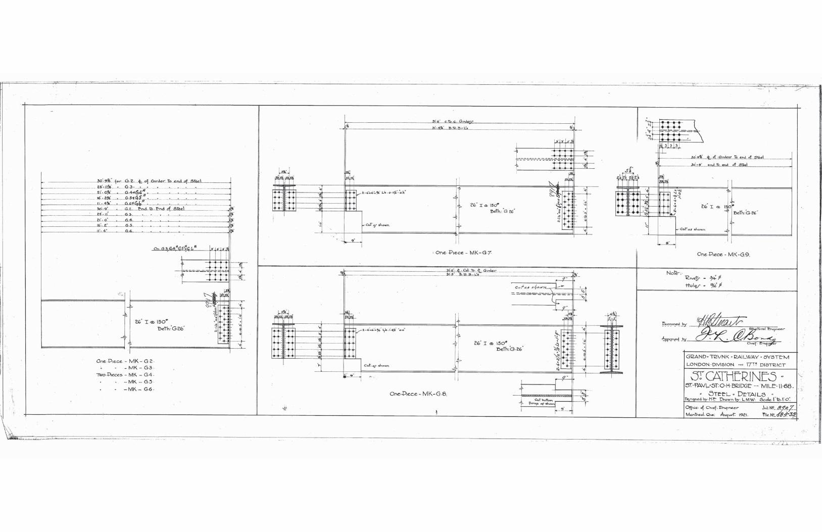
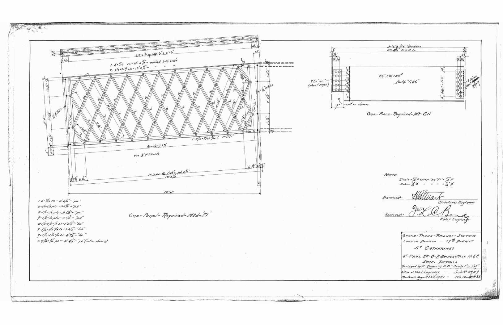
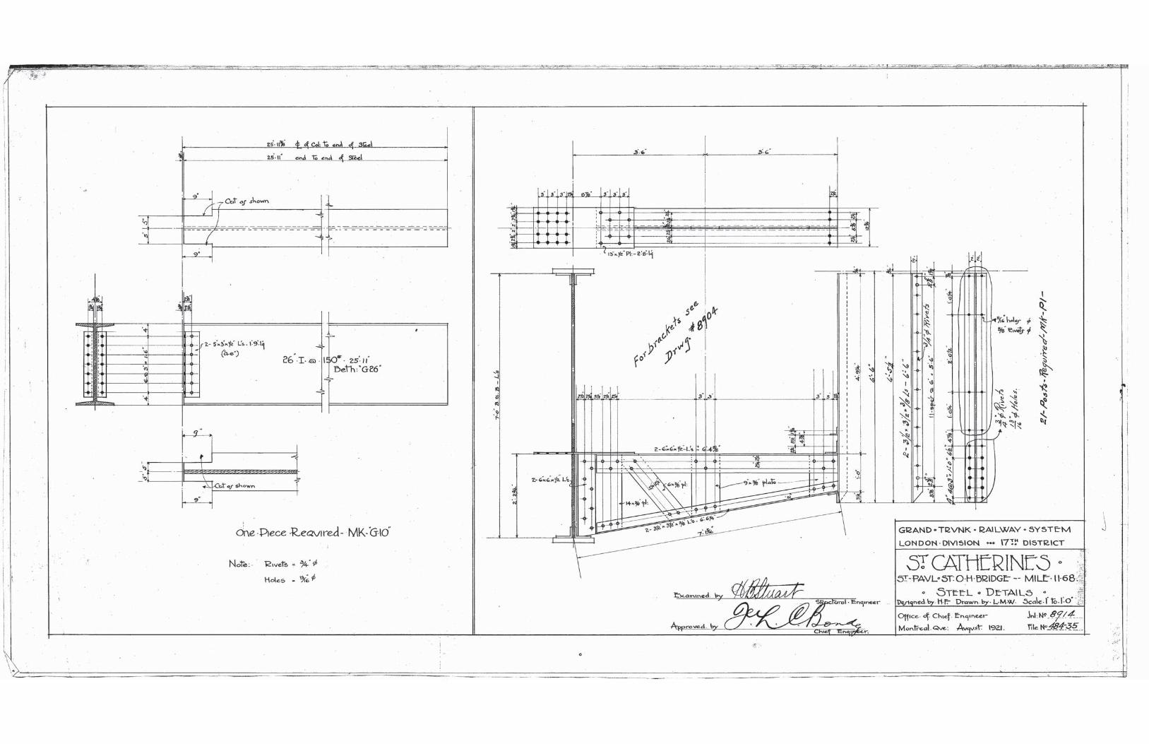
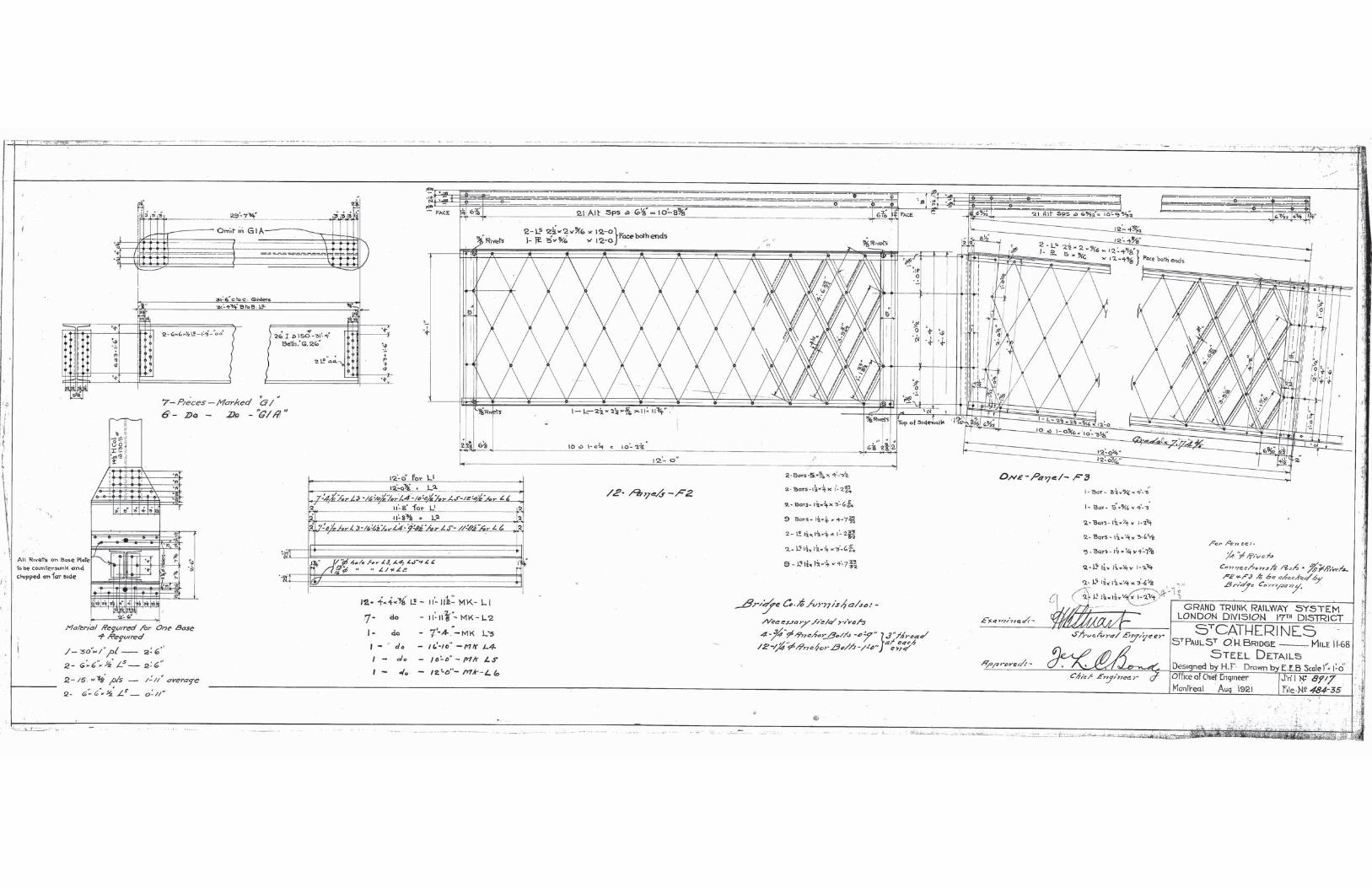
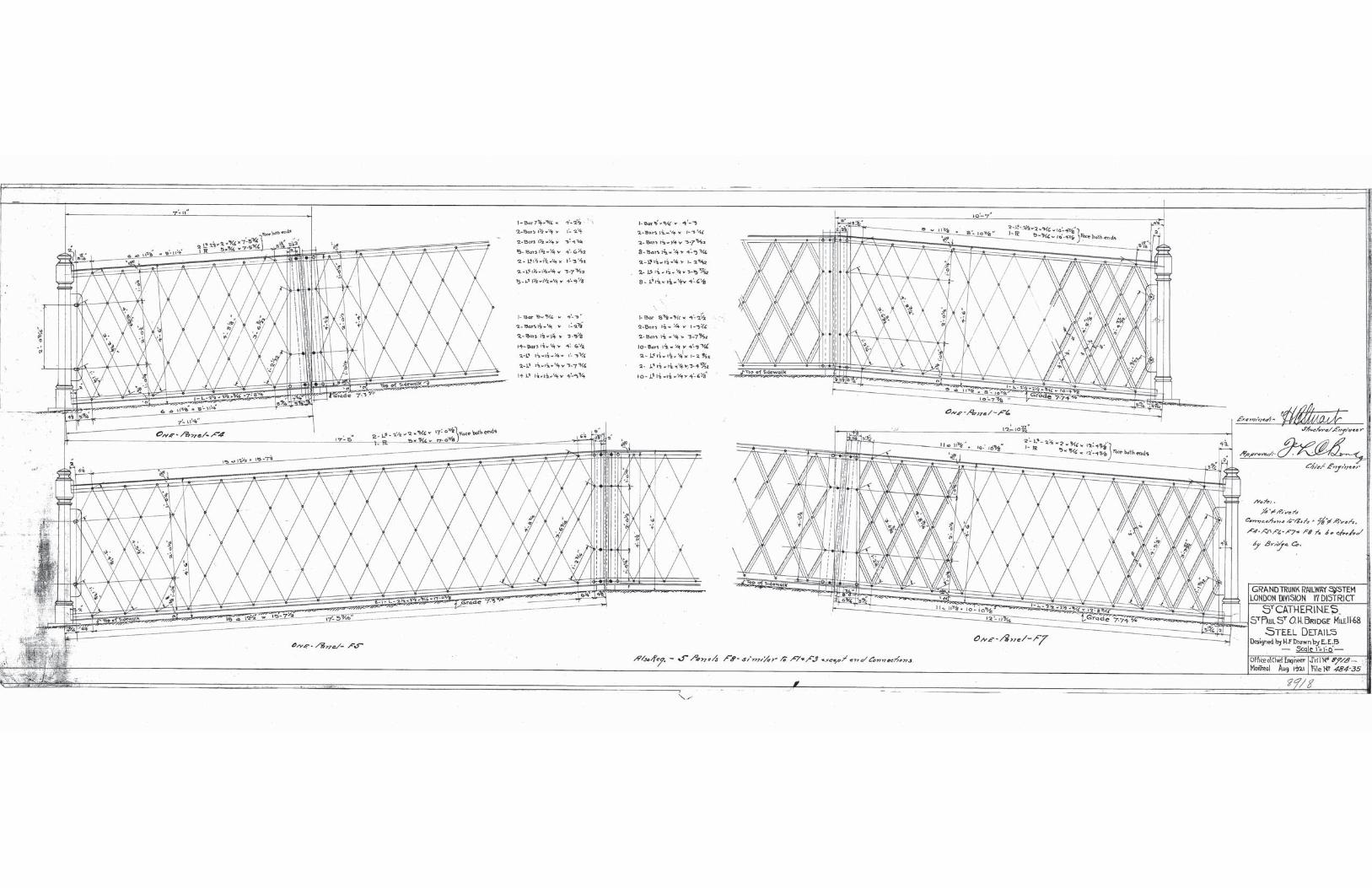
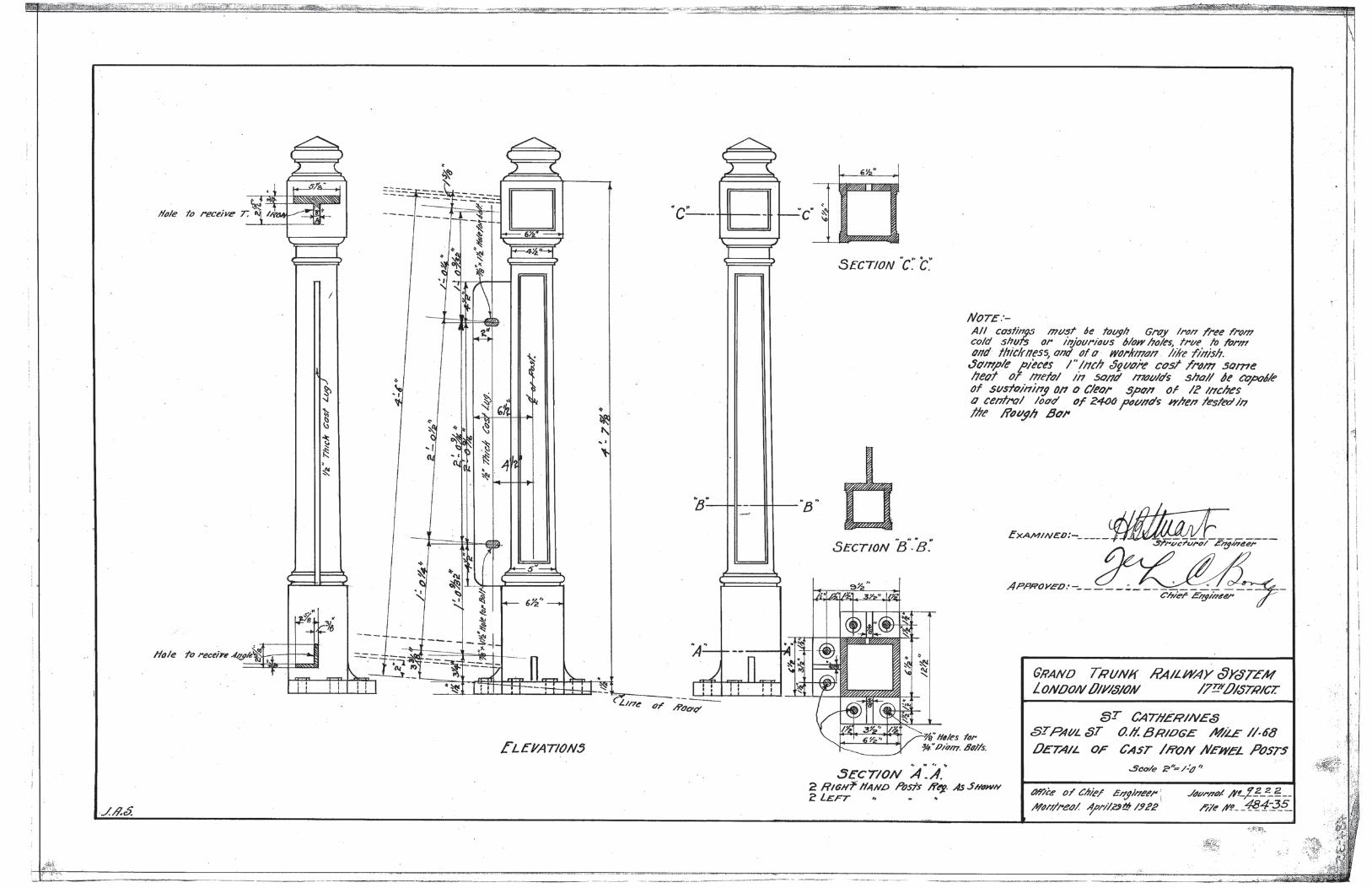
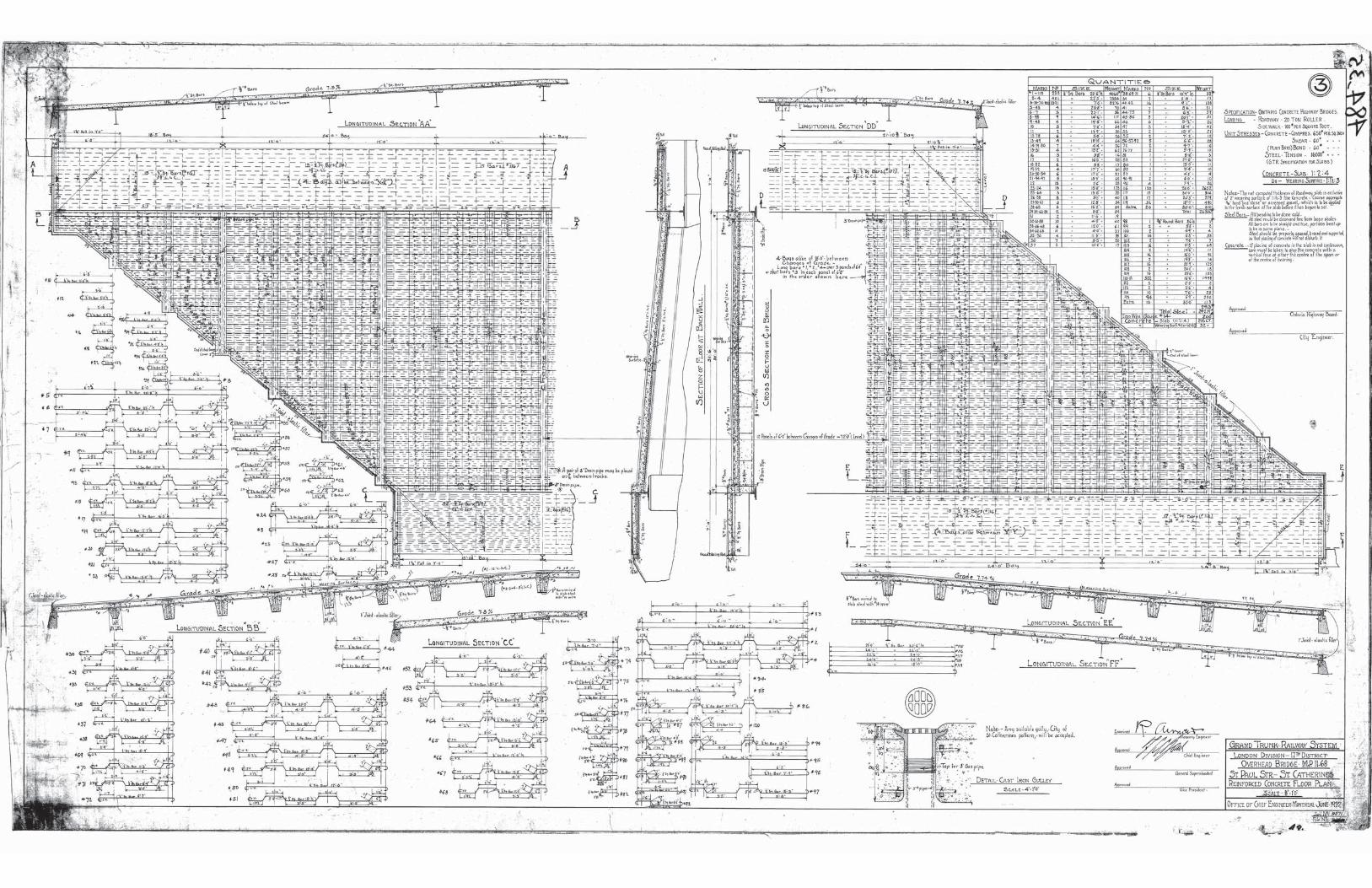
A portion of the original 1922 construction drawings and the 1977 rehabilitation drawings were
available, and are included in Appendix ‘D’. There are no available drawings of the main girders
and there is evidence that the girders may have been salvaged from a previous structure.
Currently, the structure is posted with a triple load limit of 15, 30, and 40 tonnes on both
approaches. This posting was installed between 2011 and 2013. This posting is based on a load
capacity evaluation completed by CNR. However, CNR has not provided this report to the Niagara
Region.
There is a 20km/h posted warning speed at the bridge as the approaches have steep grades (7.3%
and 7.74%) which limit visibility.
There is a board order for this structure, outlining the agreements between the railway company
and the local municipalities.
1
2. INSPECTION
2.1 Verification of Bridge Drawings
It appears that the structure was generally constructed as per the original 1922 drawings and
rehabilitated as per the 1977 rehabilitation drawings. Drawings of the main girders were not
available, and the girders were therefore measured on site. There are conflicting details on the
original drawings for the steel overhang supports. The dimensions of the steel supports were
measured on site. The configuration of the pier cross-bracing is different from what is shown on
the drawings. The true cross-bracing configuration was measured and used in the analysis.
2.2 Effects of Deterioration
We have reviewed the “2017 Municipal Bridge Appraisal, Rehabilitation/Replacement Needs” report (2017, ELLIS Engineering Inc.). According to the report, the bridge is in poor condition. The
inspection report recommended that the structure be replaced NOW.
We completed a visual inspection of the structure on September 11, 2018 to quantify the extent
of deterioration and areas of structural concern. Several structural components could not be fully
inspected due to limited access over the railway and due to concrete encasement. Photographs
showing the effects of deterioration throughout the structure are included in Appendix ‘A’.
Roadway and Sidewalks
The approaches to the structure are steep and there is poor visibility over the structure. The
asphalt roadway on the approaches is in fair condition with areas of wide transverse cracking and
isolated areas of alligator cracking and settlement. The asphalt roadway over the structure is in
poor condition with wide transverse and longitudinal cracks throughout the deck and severe
potholes with exposed portions of the concrete bridge deck.
The sidewalks on the approaches have settled and are uneven. There are areas of severe concrete
disintegration along the curbs. The sidewalks over the bridge are in poor condition. The north
sidewalk is sloping off the structure to the north and the south sidewalk is sloping off the
structure to the south. There are longitudinal cracks in the north and south sidewalks indicating
rotation of both sidewalks. Asphalt and concrete patch repairs have been completed on sections
of the south sidewalk. However, there are light to medium delaminations and spalls on the south
sidewalk. As a result of the settlement on the approaches, there are steep sidewalks connecting
the bridge sidewalk to the approach sidewalk which may limit pedestrian accessibility over the
bridge.
The steel pedestrian railings over the bridge are in poor condition and are leaning outwards. The
connections at the base of the pedestrian rail posts are deformed due to crevice corrosion and
several of the connections are loose.
2
Steel Through-Plate Girders
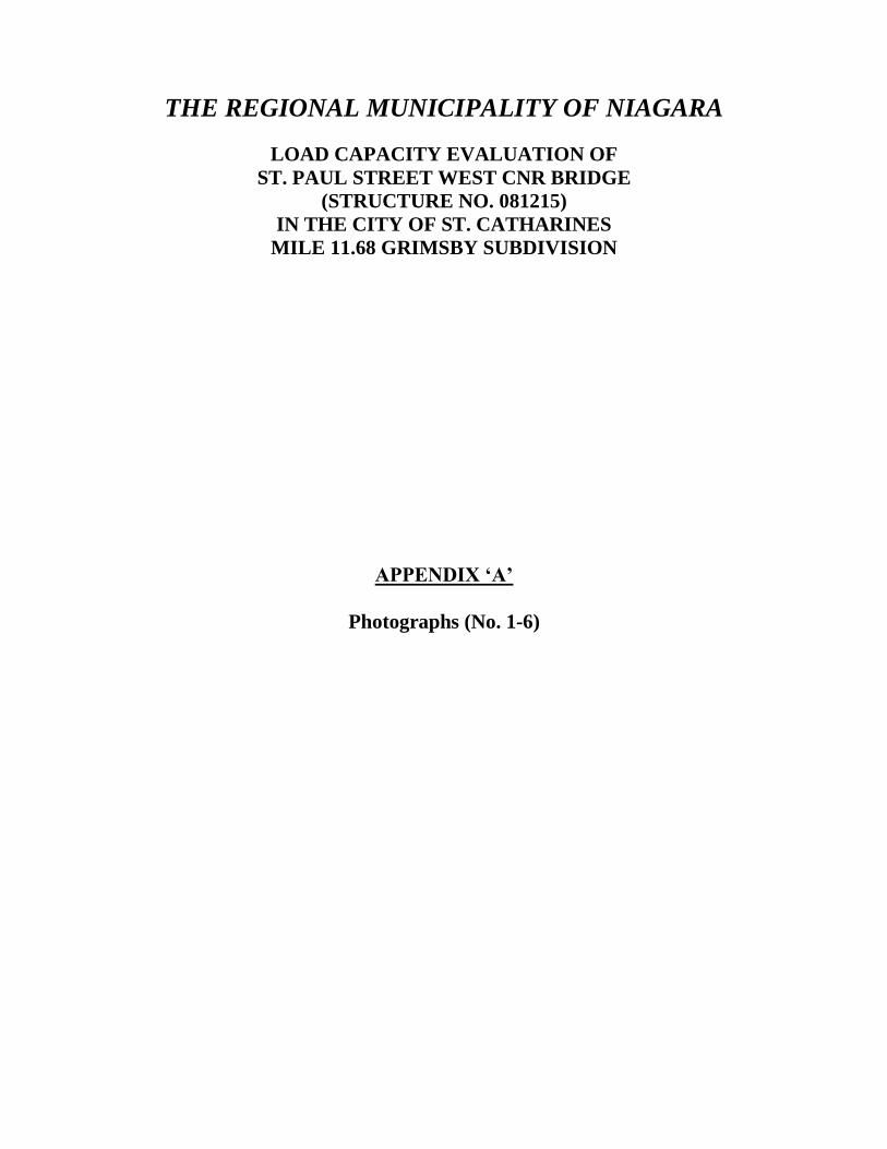
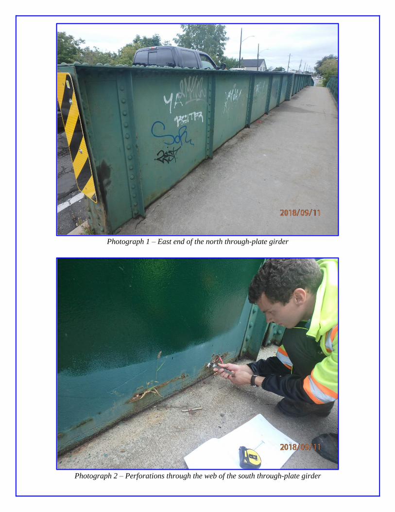
The main steel through-plate girders above the bridge deck are in poor condition. There is severe
corrosion and section loss of the webs along the sidewalks and curbs. There is an area of severe
corrosion and web perforation (approximately 600mm long and up to 25mm wide) at the curb
line of the south girder of the west span near the west column. Several of the stiffeners are
perforated at the sidewalk level. There is severe crevice corrosion between the built-up flange
plates that has warped the plates and caused several rivets to fail. The east end of the south
through-plate girder has rotated to the west.
The connection between the top of the northwest pier column and the west span north through-
plate girder is beginning to separate (25mm) and has caused several rivets to fail. These rivets
have been replaced with bolts.
The longitudinal through-plate girders below the bridge deck are in poor condition with areas of
severe corrosion and significant loss of cross-sectional area and loss of rivet heads at the
abutments. There is severe section loss and perforations through the bottom flange next to all the
bearings.
Transverse Stringers
The transverse 'I' beam stringers of the bridge deck have been filled with concrete. Only the
bottom flanges could be inspected. The bottom flanges of the transverse stringers are generally in
fair condition, with areas of severe corrosion at the connections with the through-plate girders.
Substructure
The steel piers are generally in fair condition. There are areas of severe corrosion at the gusset
plates at the bases of the columns. The gusset plates connecting the lateral cross bracing have
buckled likely due to deformation from severe crevice corrosion.
The abutment walls and wingwalls are in poor condition with areas of severe cracking and
concrete disintegration. At the east abutment there is a wide vertical crack with severe spalling
next to the south girder. There is a void in the roadway and ballast wall at this location.
At the west abutment a temporary support has been installed under the second transverse stringer
from the west. Concrete patch repairs have been completed next to the temporary support.
Bridge Deck Soffit
The bridge deck soffit is in very poor condition with extensive areas of severe spalling with
exposed corroding reinforcing steel, delaminations, and leakage. There is severe leakage
through the bridge deck as evident on the abutment walls.
3
3. LOAD CAPACITY EVALUATION
3.1 Structural Evaluation
The load capacity evaluation was conducted in accordance with the Canadian Highway Bridge
Design Code (CHBDC, CAN/CSA-S6-14). The unbraced lengths of the main girders were
evaluated considering U-Frame action described in the British Standard BS 5400-3 “Steel, concrete and composite bridges.”
The structural analysis was performed utilizing hand calculations and S-FRAME, a structural
finite element analysis program. The live load capacity factors and the load limit postings were
then calculated based on the results of the analysis.
S-CALC, a section properties calculator program, was used to determine the section properties of
the structural steel members. A report of the section properties is included in Appendix ‘C’.
The remaining fatigue life evaluation was performed utilizing hand calculations from the
CHBDC. The following AADT values were used for the evaluation: 7950 (1992), 9300 (2013),
and 9200 (2016). For the evaluation, the ADTT was 10% of the AADT for all years of the
structure’s life.
3.1.1 Material Properties
The following material properties were used for the load capacity evaluation:
Structural Steel
Bridge Constructed Prior to 1905 (CHBDC Table 14.1) (Used for main girders)
o Specified Yield Strength of Original Structural Steel, Fy = 180 MPa
o Specified Ultimate Strength of Original Structural Steel, Fu = 360 MPa
Bridge Constructed Between 1905 and 1932 (CHBDC Table 14.1) (Used for remaining
steel)
o Specified Yield Strength of Original Structural Steel, Fy = 210 MPa
o Specified Ultimate Strength of Original Structural Steel, Fu = 420 MPa
Concrete
Specified Compressive Strength of Reinforced Concrete Deck = 20 MPa (CHBDC
Clause 14.7.4.3)
Reinforcing Steel
Specified Yield Strength of Deck Reinforcing Steel = 230 MPa (CHBDC Table 14.2,
bridge constructed circa 1922)
4
3.1.2 Loads
The transitory (live) loads used were Level 1 Evaluation Loads (CL1-625-ONT Truck), Level 2
Evaluation Loads (CL2-625-ONT Truck) and Level 3 Evaluation Loads (CL3-625-ONT Truck)
for a Class ‘A’ Highway.
The following dead loads are applicable:
Bridge deck concrete (200mm thick);
Structural steel self-weight;
Asphalt (90mm thickness).
3.1.3 Finite Element Analysis
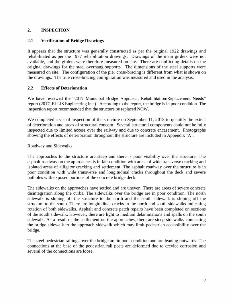
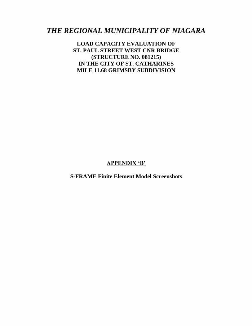
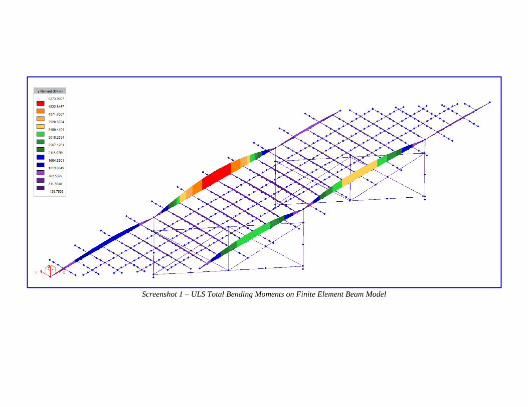
Several finite element models of the bridge were developed in S-FRAME for analysis. In
general, two types of S-FRAME models were generated. The first type was a beam model,
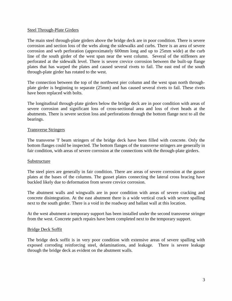
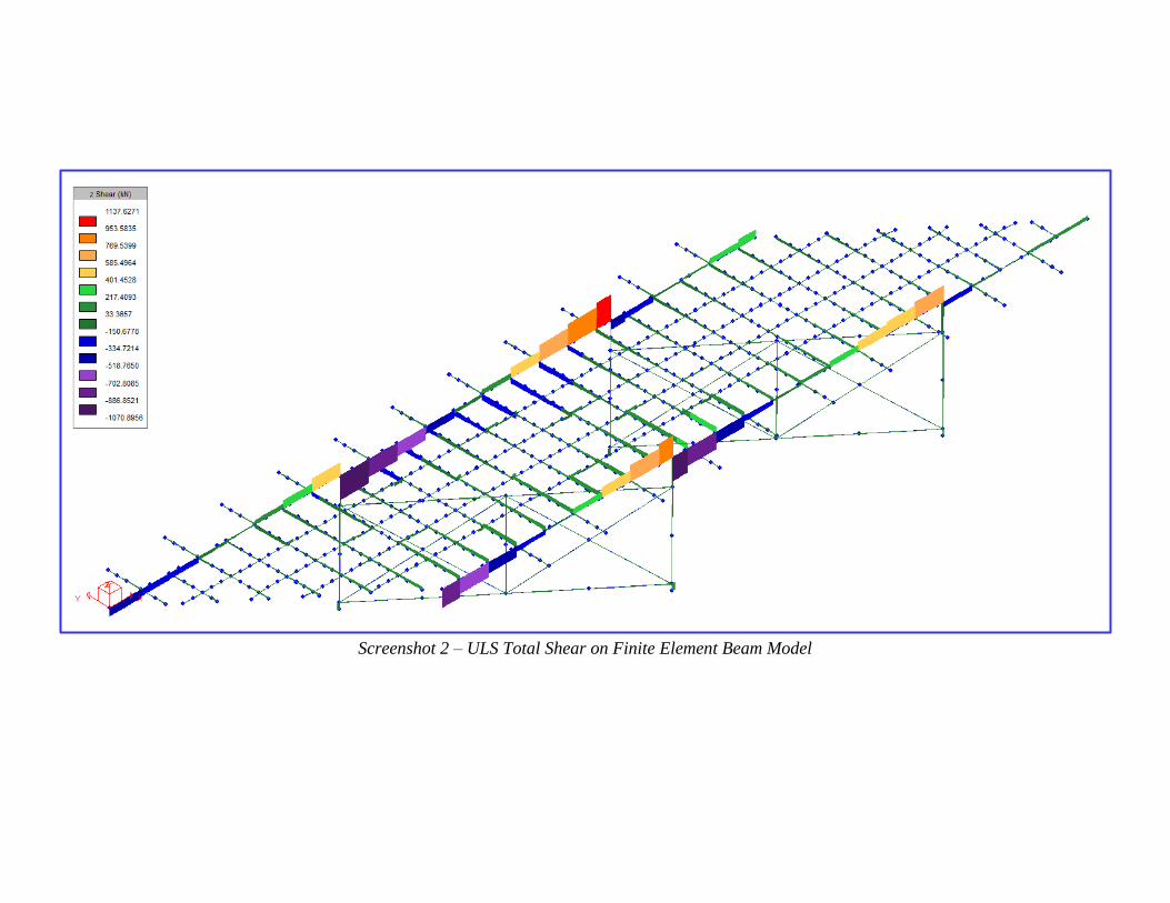
where each member was modelled as a beam. The second type was a mesh model, where the
longitudinal main girders, stringers, and concrete deck were modelled with shell elements.
A screenshot of the south side of the beam model is shown in Figure 1.
Figure 1: Finite Element Beam Model
A screenshot of the south side of the mesh model is shown in Figure 2.
Figure 2: Finite Element Mesh Model
Additional screenshots of the S-FRAME finite element models are included in Appendix ‘B’.
5
With the beam model, various end conditions of the main girders were investigated (pinned and
fixed). It was also assumed that the compression flanges of the main girders were laterally
restrained by U-frame behaviour of the web stiffeners and transverse stringers (British Standard
– Steel, concrete and composite bridges - BS 5400-3).
The mesh model was used to analyze the stresses in the girders at critical locations and to
confirm the results of the beam model. The mesh model was also used to investigate the effects
of web perforations on the stresses within the girders.
The girders and transverse stringers were analyzed for maximum bending moment and shear.
The pier columns were analyzed for axial compression and bending moment. The concrete deck
was analyzed for punching shear.
A section loss of 20% was assumed for all structural steel elements to represent the effects of
deterioration.
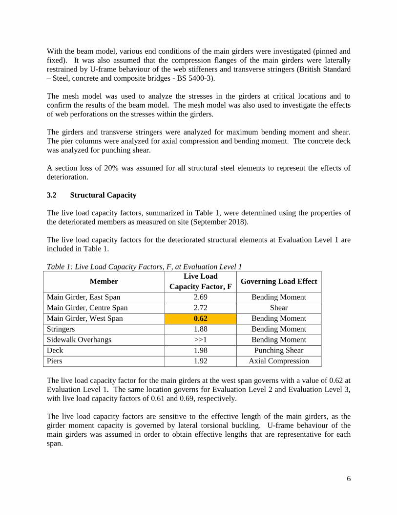
3.2 Structural Capacity
The live load capacity factors, summarized in Table 1, were determined using the properties of
the deteriorated members as measured on site (September 2018).
The live load capacity factors for the deteriorated structural elements at Evaluation Level 1 are
included in Table 1.
Table 1: Live Load Capacity Factors, F, at Evaluation Level 1
Member Live Load
Capacity Factor, F Governing Load Effect
Main Girder, East Span 2.69 Bending Moment
Main Girder, Centre Span 2.72 Shear
Main Girder, West Span 0.62 Bending Moment
Stringers 1.88 Bending Moment
Sidewalk Overhangs >>1 Bending Moment
Deck 1.98 Punching Shear
Piers 1.92 Axial Compression
The live load capacity factor for the main girders at the west span governs with a value of 0.62 at
Evaluation Level 1. The same location governs for Evaluation Level 2 and Evaluation Level 3,
with live load capacity factors of 0.61 and 0.69, respectively.
The live load capacity factors are sensitive to the effective length of the main girders, as the
girder moment capacity is governed by lateral torsional buckling. U-frame behaviour of the
main girders was assumed in order to obtain effective lengths that are representative for each
span.
6
The structural steel girders were checked with the properties of steel fabricated prior to 1905 and
of steel fabricated between 1905 and 1932. The different steel properties produce the same live
load capacity factor at the critical location for the governing member (Main Girder, West Span).
From the finite element beam model, the location of the governing bending moment was found
in the west span near the west abutment. This location was investigated further with the finite
element mesh model, where the stresses in the webs and flanges were further analyzed.
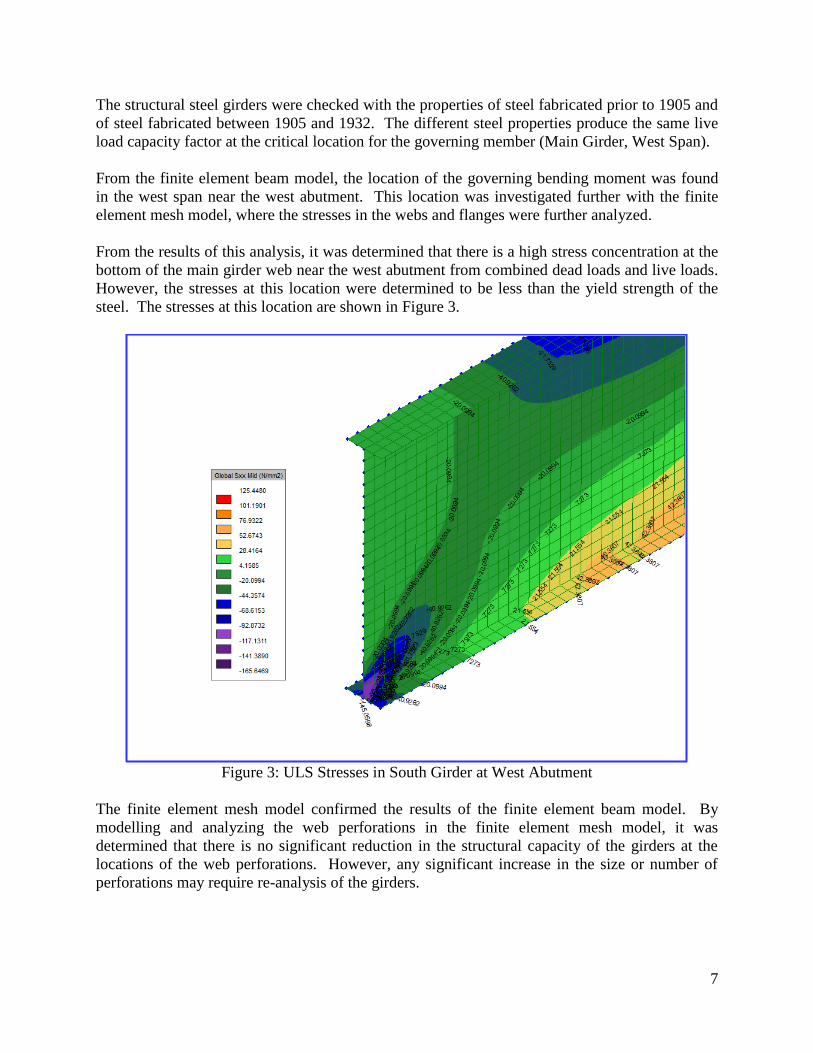
From the results of this analysis, it was determined that there is a high stress concentration at the
bottom of the main girder web near the west abutment from combined dead loads and live loads.
However, the stresses at this location were determined to be less than the yield strength of the
steel. The stresses at this location are shown in Figure 3.
Figure 3: ULS Stresses in South Girder at West Abutment
The finite element mesh model confirmed the results of the finite element beam model. By
modelling and analyzing the web perforations in the finite element mesh model, it was
determined that there is no significant reduction in the structural capacity of the girders at the
locations of the web perforations. However, any significant increase in the size or number of
perforations may require re-analysis of the girders.
7
The riveted connections of the girders to the pier columns were analyzed for live load capacity.
It was determined that the rivets at the top of the connection do not have sufficient structural
capacity to carry live loads. This confirms the observations from the site inspection, where the
top rivets of the northwest column have failed and the west span north through-plate girder is
beginning to separate (Appendix ‘A’, Photograph 3). The failed rivets at this location have been
replaced with bolts.
Due to the deterioration of the structure, the governing live load capacity factor is 0.62 and the
following triple load limit posting is required:
Level 3 – 16 tonnes. (Single Unit Vehicles)
Level 2 – 26 tonnes. (Two Unit Vehicles - Tractor-trailer, Semi-trailer or
Single Unit Vehicle-trailer)
Level 1 – 38 tonnes. (Vehicle Trains - Tractor with more than one trailer)
The current load posting of 15, 30, and 40 tonnes is similar to the results from this load capacity
evaluation.
The concrete deck was analyzed for punching shear in accordance with the bridge code. No
immediate concerns were found for live load punching through the deck. However, with the
severe spalling of the underside of the concrete deck, continued deterioration may result in small
holes developing in the deck.
3.3 Remaining Fatigue Life
An evaluation of the remaining fatigue life was completed on areas of the bridge with fatigue-
prone details. These areas include the riveted connections of the built-up steel plate girders and
the riveted connections between the stringers and the girders.
From the evaluation, it was determined that the riveted connections between the stringers and the
girders are the most critical for fatigue. The remaining fatigue life of these connections is
approximately 20-30 years. However, this greatly exceeds the expected residual life of the
bridge.
8
4. CONCLUSION & RECOMMENDATIONS
The results of our analysis conclude that the main girders are the most over-utilized members
with governing live load capacity factors of 0.62, 0.61, and 0.69 at Evaluation Level 1,
Evaluation Level 2, and Evaluation Level 3, respectively.
The load capacity evaluation results in a triple load posting of 16, 26, and 38 tonnes. As the
findings of the structural analysis are similar to the current load posting, we recommend
maintaining the current load posting of 15, 30, and 40 tonnes.
There are no immediate concerns with fatigue-prone areas on the bridge.
Due to severe deterioration and section loss, we recommend inspecting the structure for further
deterioration and displacements every six months until the structure is replaced. The structural
steel shall be checked for any increase in section loss or perforations, particularly at the bottom
flanges and the webs of the main girders. The concrete deck shall be inspected for punch holes.
If further deterioration is found, an updated load capacity evaluation may be required.
We agree with the 2017 inspection report that, due to the deteriorated state of the bridge and poor
roadway geometry, the structure should be replaced NOW.
9
THE REGIONAL MUNICIPALITY OF NIAGARA
LOAD CAPACITY EVALUATION OF
ST. PAUL STREET WEST CNR BRIDGE
(STRUCTURE NO. 081215)
IN THE CITY OF ST. CATHARINES
MILE 11.68 GRIMSBY SUBDIVISION
APPENDIX ‘A’
Photographs (No. 1-6)
Photograph 1 – East end of the north through-plate girder
Photograph 2 – Perforations through the web of the south through-plate girder
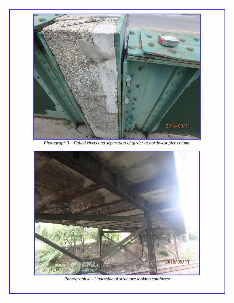
Photograph 3 – Failed rivets and separation of girder at northwest pier column
Photograph 4 – Underside of structure looking southwest
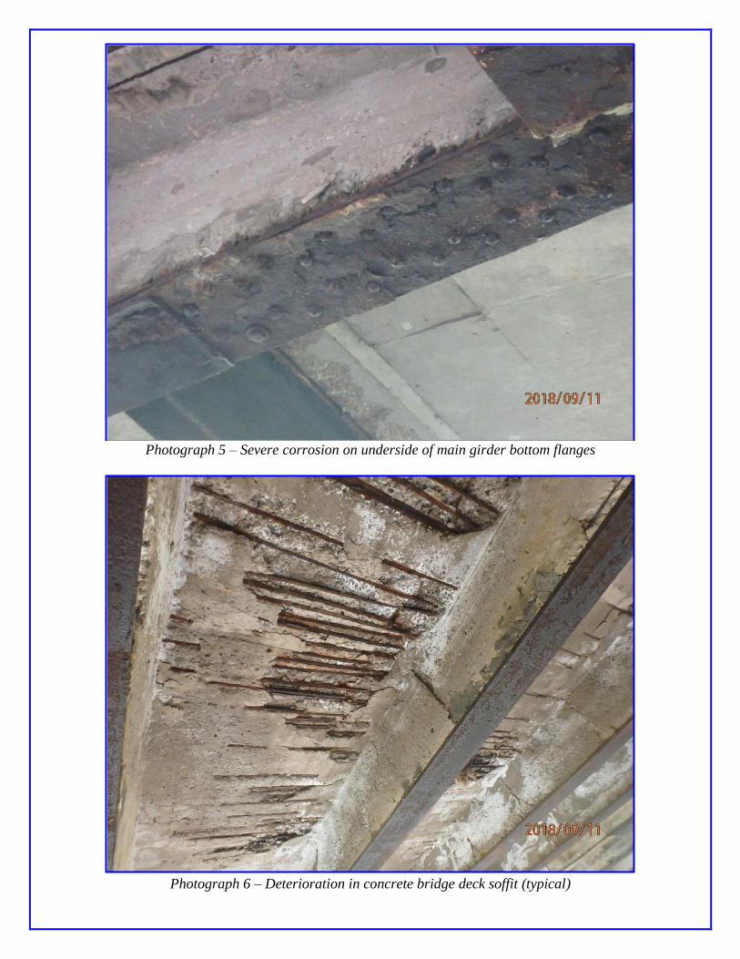
Photograph 5 – Severe corrosion on underside of main girder bottom flanges
Photograph 6 – Deterioration in concrete bridge deck soffit (typical)
THE REGIONAL MUNICIPALITY OF NIAGARA
LOAD CAPACITY EVALUATION OF
ST. PAUL STREET WEST CNR BRIDGE
(STRUCTURE NO. 081215)
IN THE CITY OF ST. CATHARINES
MILE 11.68 GRIMSBY SUBDIVISION
APPENDIX ‘B’
S-FRAME Finite Element Model Screenshots
Screenshot 1 – ULS Total Bending Moments on Finite Element Beam Model
Screenshot 2 – ULS Total Shear on Finite Element Beam Model
Screenshot 3 – SLS Stresses on Main Girders in the Finite Element Mesh Model
THE REGIONAL MUNICIPALITY OF NIAGARA
LOAD CAPACITY EVALUATION OF
ST. PAUL STREET WEST CNR BRIDGE
(STRUCTURE NO. 081215)
IN THE CITY OF ST. CATHARINES
MILE 11.68 GRIMSBY SUBDIVISION
APPENDIX ‘C’
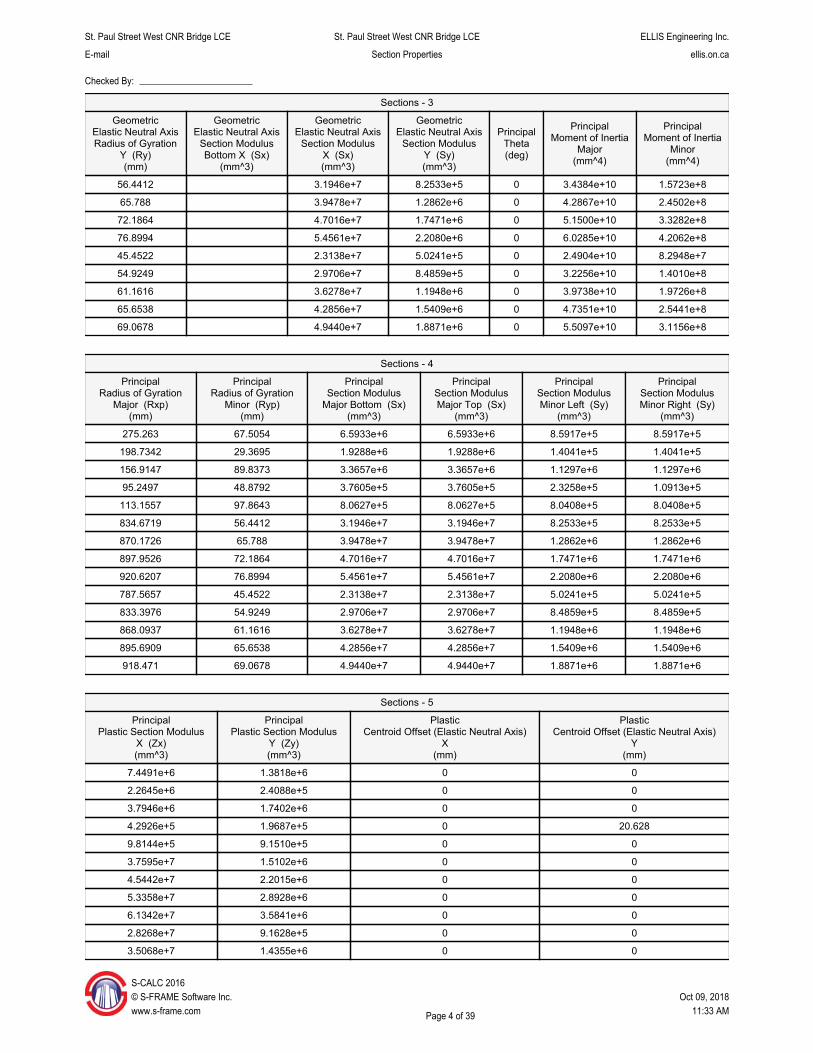
Structural Steel Section Properties Report
St. Paul Street West CNR Bridge LCE Section Properties
Load Capacity Evaluation
Darryl Bakker ELLIS Engineering Inc. 214 Martindale Rd., Suite 201 St. Catharines, Ontario Canada L2S 0B2 905-934-9049 ellis.on.ca
S©w
-CALC 2016 S-FRAME Software Inc. ww.s-frame.com
Table Of Contents
Sections ........................................................................................................... 3 - 7
Materials ................................................................................................................ 8
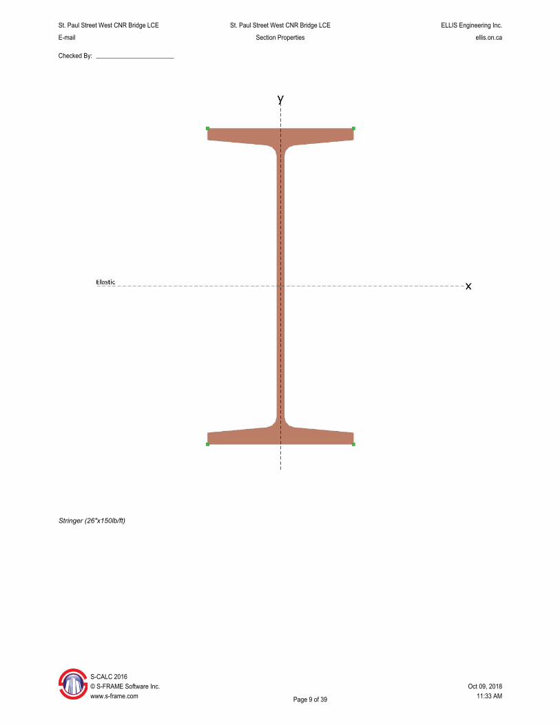
1 - Stringer (26"x150lb/ft) ............................................................................... 9 - 11
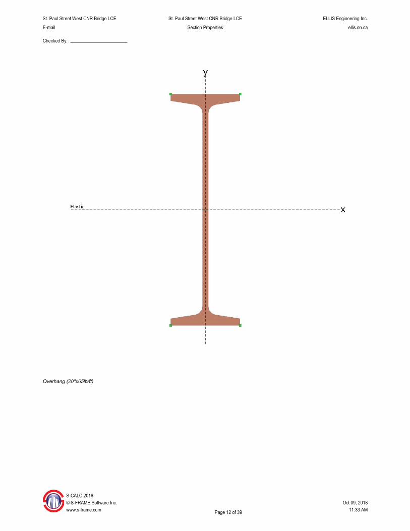
4 - Overhang (20"x65lb/ft) ............................................................................ 12 - 14
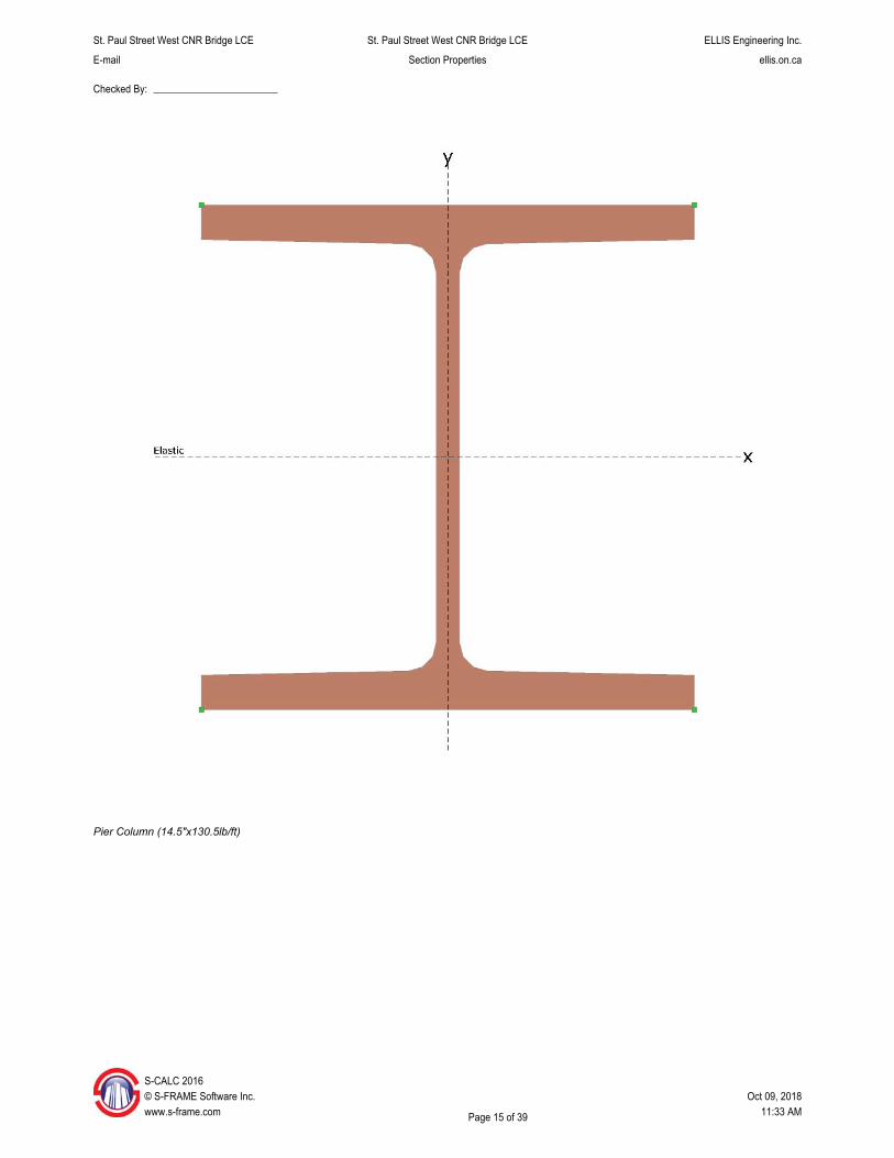
5 - Pier Column (14.5"x130.5lb/ft) ................................................................ 15 - 17
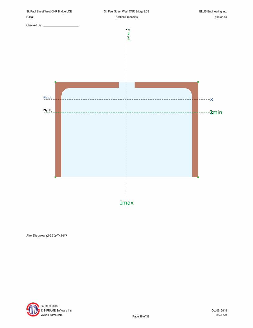
6 - Pier Diagonal (2-L6"x4"x3/8") ................................................................. 18 - 19
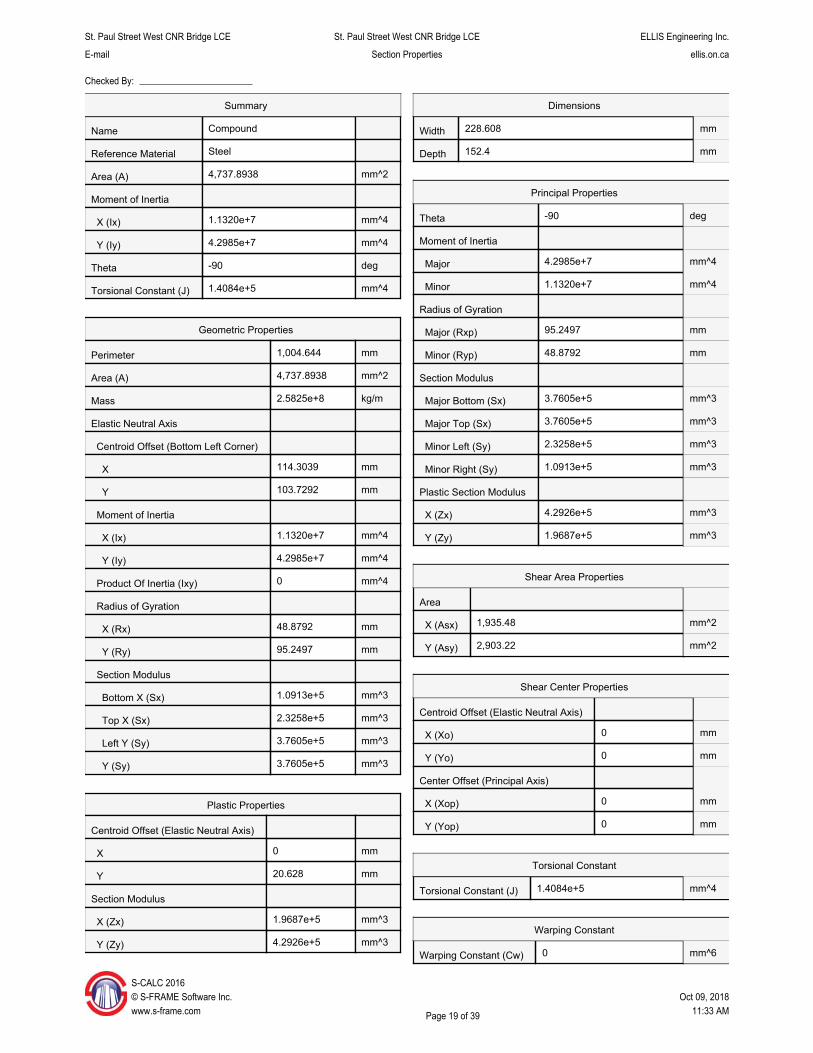
7 - Pier Strut (2-C12"x25lb/ft) ....................................................................... 20 - 21
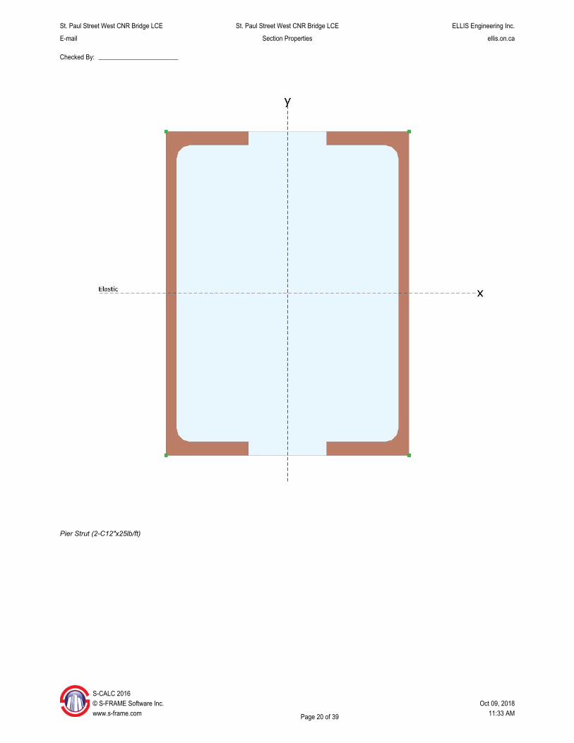
11 - Main Girder (15" x 1 Plate) ................................................................... 22 - 23
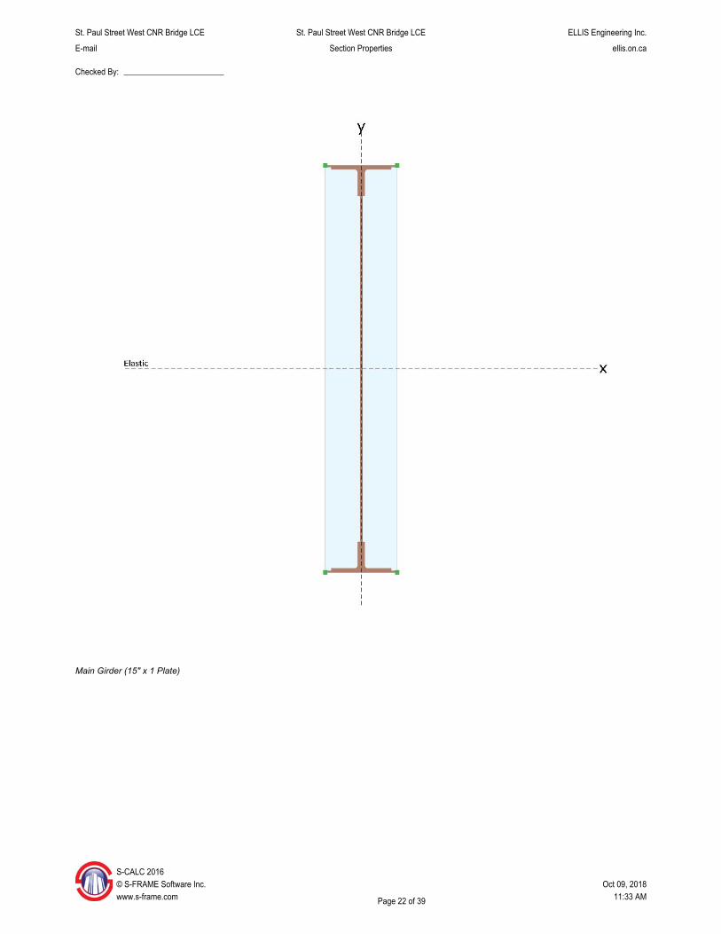
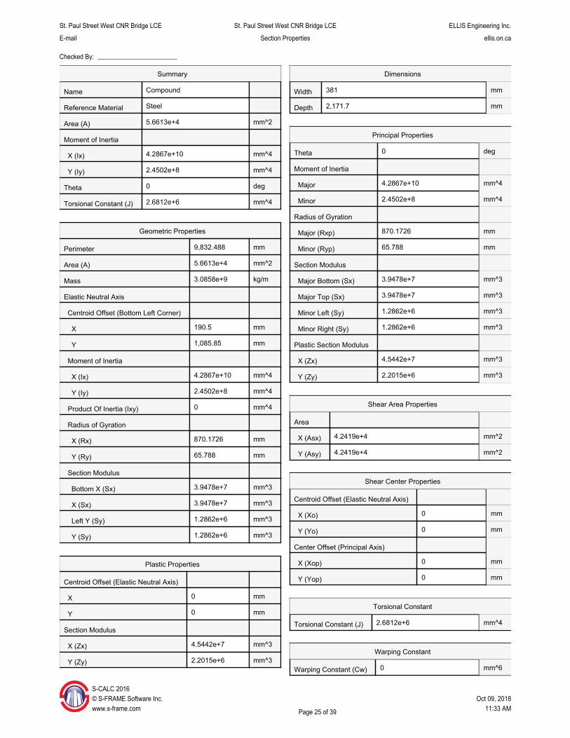
12 - Main Girder (15" x 2 Plates) .................................................................. 24 - 25
13 - Main Girder (15" x 3 Plates) .................................................................. 26 - 27
14 - Main Girder (15" x 4 Plates) .................................................................. 28 - 29
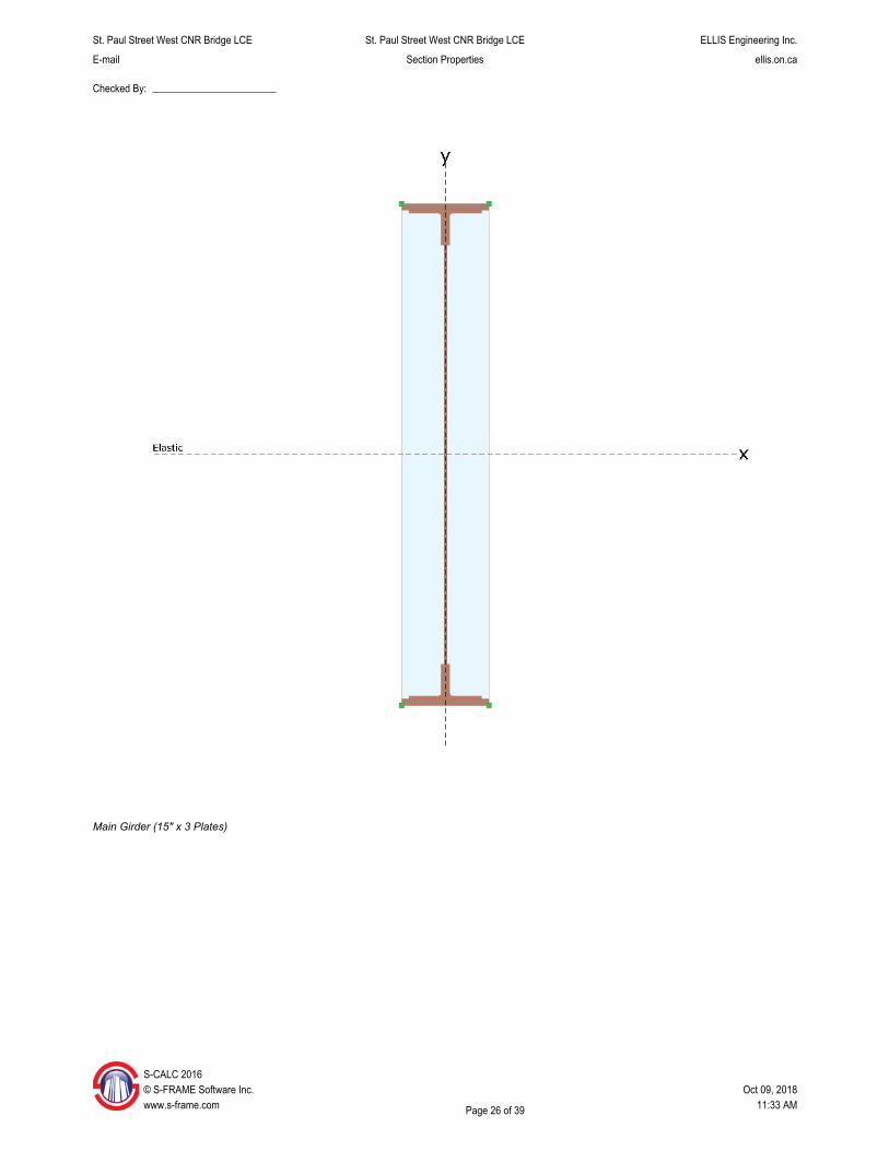
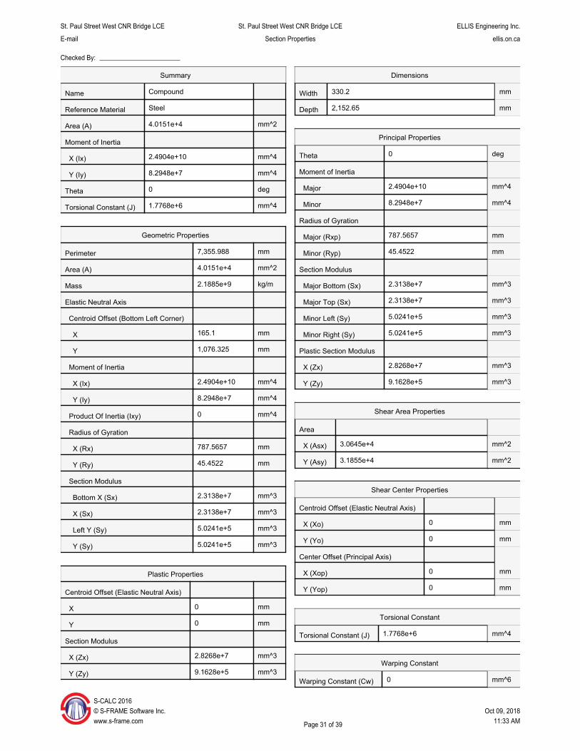
15 - Main Girder (13" x 1 Plate) ................................................................... 30 - 31
16 - Main Girder (13" x 2 Plates) .................................................................. 32 - 33
17 - Main Girder (13" x 3 Plates) .................................................................. 34 - 35
18 - Main Girder (13" x 4 Plates) .................................................................. 36 - 37
19 - Main Girder (13" x 5 Plates) .................................................................. 38 - 39
Page 2 of 39
St. Paul Street West CNR Bridge LCE St. Paul Street West CNR Bridge LCE ELLIS Engineering Inc.
E-mail Section Properties ellis.on.ca
Checked By:
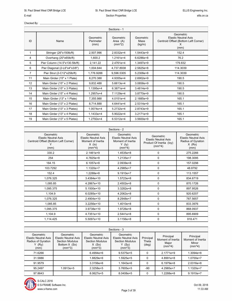
Sections - 1
ID Name Geometric Perimeter
(mm)
Geometric Area (A) (mm^2)
Geometric Mass (kg/m)
Geometric Elastic Neutral Axis
Centroid Offset (Bottom Left Corner) X
(mm)
1 Stringer (26"x150lb/ft) 2,507.996 2.8332e+4 1.5443e+9 152.4
4 Overhang (20"x65lb/ft) 1,600.2 1.2161e+4 6.6286e+8 76.2
5 Pier Column (14.5"x130.5lb/ft) 2,141.22 2.4761e+4 1.3497e+9 179.832
6 Pier Diagonal (2-L6"x4"x3/8") 1,004.644 4,737.8938 2.5825e+8 114.3039
7 Pier Strut (2-C12"x25lb/ft) 1,776.9288 9,596.5305 5.2308e+8 114.3039
11 Main Girder (15" x 1 Plate) 8,270.388 4.9355e+4 2.6902e+9 190.5
12 Main Girder (15" x 2 Plates) 9,832.488 5.6613e+4 3.0858e+9 190.5
13 Main Girder (15" x 3 Plates) 1.1395e+4 6.3871e+4 3.4814e+9 190.5
14 Main Girder (15" x 4 Plates) 1.2957e+4 7.1129e+4 3.8770e+9 190.5
15 Main Girder (13" x 1 Plate) 7,355.988 4.0151e+4 2.1885e+9 165.1
16 Main Girder (13" x 2 Plates) 8,714.888 4.6441e+4 2.5314e+9 165.1
17 Main Girder (13" x 3 Plates) 1.0074e+4 5.2732e+4 2.8743e+9 165.1
18 Main Girder (13" x 4 Plates) 1.1433e+4 5.9022e+4 3.2171e+9 165.1
19 Main Girder (13" x 5 Plates) 1.2792e+4 6.5312e+4 3.5600e+9 165.1
Sections - 2
Geometric Elastic Neutral Axis
Centroid Offset (Bottom Left Corner) Y
(mm)
Geometric Elastic Neutral Axis Moment of Inertia
X (Ix) (mm^4)
Geometric Elastic Neutral Axis Moment of Inertia
Y (Iy) (mm^4)
Geometric Elastic Neutral Axis
Product Of Inertia (Ixy) (mm^4)
Geometric Elastic Neutral Axis Radius of Gyration
X (Rx) (mm)
330.2 2.1461e+9 1.4535e+8 0 275.2266
254 4.7825e+8 1.2135e+7 0 198.3095
184.15 6.1057e+8 2.0939e+8 0 157.0298
103.7292 1.1320e+7 4.2985e+7 0 48.8792
152.4 1.2288e+8 9.1910e+7 0 113.1557
1,076.325 3.4384e+10 1.5723e+8 0 834.6719
1,085.85 4.2867e+10 2.4502e+8 0 870.1726
1,095.375 5.1500e+10 3.3282e+8 0 897.9526
1,104.9 6.0285e+10 4.2062e+8 0 920.6207
1,076.325 2.4904e+10 8.2948e+7 0 787.5657
1,085.85 3.2256e+10 1.4010e+8 0 833.3976
1,095.375 3.9738e+10 1.9726e+8 0 868.0937
1,104.9 4.7351e+10 2.5441e+8 0 895.6909
1,114.425 5.5097e+10 3.1156e+8 0 918.471
Sections - 3
Geometric Elastic Neutral Axis Radius of Gyration
Y (Ry) (mm)
Geometric Elastic Neutral Axis
Section Modulus Bottom X (Sx)
(mm^3)
Geometric Elastic Neutral Axis
Section Modulus X (Sx) (mm^3)
Geometric Elastic Neutral Axis
Section Modulus Y (Sy) (mm^3)
Principal Theta (deg)
Principal Moment of Inertia
Major (mm^4)
Principal Moment of Inertia
Minor (mm^4)
71.6266 6.4994e+6 9.5375e+5 0 2.1771e+9 1.3094e+8
31.5886 1.8829e+6 1.5925e+5 0 4.8991e+8 1.0700e+7
91.9579 3.3156e+6 1.1643e+6 0 6.1979e+8 2.0316e+8
95.2497 1.0913e+5 2.3258e+5 3.7605e+5 -90 4.2985e+7 1.1320e+7
97.8643 8.0627e+5 8.0408e+5 0 1.2288e+8 9.1910e+7
S-CALC 2016 © S-FRAME Software Inc. Oct 09, 2018 www.s-frame.com Page 3 of 39 11:33 AM
St. Paul Street West CNR Bridge LCE St. Paul Street West CNR Bridge LCE ELLIS Engineering Inc.
E-mail Section Properties ellis.on.ca
Checked By:
Sections - 3
Geometric Elastic Neutral Axis Radius of Gyration
Y (Ry) (mm)
Geometric Elastic Neutral Axis
Section Modulus Bottom X (Sx)
(mm^3)
Geometric Elastic Neutral Axis
Section Modulus X (Sx) (mm^3)
Geometric Elastic Neutral Axis
Section Modulus Y (Sy) (mm^3)
Principal Theta (deg)
Principal Moment of Inertia
Major (mm^4)
Principal Moment of Inertia
Minor (mm^4)
56.4412 3.1946e+7 8.2533e+5 0 3.4384e+10 1.5723e+8
65.788 3.9478e+7 1.2862e+6 0 4.2867e+10 2.4502e+8
72.1864 4.7016e+7 1.7471e+6 0 5.1500e+10 3.3282e+8
76.8994 5.4561e+7 2.2080e+6 0 6.0285e+10 4.2062e+8
45.4522 2.3138e+7 5.0241e+5 0 2.4904e+10 8.2948e+7
54.9249 2.9706e+7 8.4859e+5 0 3.2256e+10 1.4010e+8
61.1616 3.6278e+7 1.1948e+6 0 3.9738e+10 1.9726e+8
65.6538 4.2856e+7 1.5409e+6 0 4.7351e+10 2.5441e+8
69.0678 4.9440e+7 1.8871e+6 0 5.5097e+10 3.1156e+8
Sections - 4
Principal Radius of Gyration
Major (Rxp) (mm)
Principal Radius of Gyration
Minor (Ryp) (mm)
Principal Section Modulus
Major Bottom (Sx) (mm^3)
Principal Section Modulus Major Top (Sx)
(mm^3)
Principal Section Modulus Minor Left (Sy)
(mm^3)
Principal Section Modulus Minor Right (Sy)
(mm^3)
275.263 67.5054 6.5933e+6 6.5933e+6 8.5917e+5 8.5917e+5
198.7342 29.3695 1.9288e+6 1.9288e+6 1.4041e+5 1.4041e+5
156.9147 89.8373 3.3657e+6 3.3657e+6 1.1297e+6 1.1297e+6
95.2497 48.8792 3.7605e+5 3.7605e+5 2.3258e+5 1.0913e+5
113.1557 97.8643 8.0627e+5 8.0627e+5 8.0408e+5 8.0408e+5
834.6719 56.4412 3.1946e+7 3.1946e+7 8.2533e+5 8.2533e+5
870.1726 65.788 3.9478e+7 3.9478e+7 1.2862e+6 1.2862e+6
897.9526 72.1864 4.7016e+7 4.7016e+7 1.7471e+6 1.7471e+6
920.6207 76.8994 5.4561e+7 5.4561e+7 2.2080e+6 2.2080e+6
787.5657 45.4522 2.3138e+7 2.3138e+7 5.0241e+5 5.0241e+5
833.3976 54.9249 2.9706e+7 2.9706e+7 8.4859e+5 8.4859e+5
868.0937 61.1616 3.6278e+7 3.6278e+7 1.1948e+6 1.1948e+6
895.6909 65.6538 4.2856e+7 4.2856e+7 1.5409e+6 1.5409e+6
918.471 69.0678 4.9440e+7 4.9440e+7 1.8871e+6 1.8871e+6
Sections - 5
Principal Plastic Section Modulus
X (Zx) (mm^3)
Principal Plastic Section Modulus
Y (Zy) (mm^3)
Plastic Centroid Offset (Elastic Neutral Axis)
X (mm)
Plastic Centroid Offset (Elastic Neutral Axis)
Y (mm)
7.4491e+6 1.3818e+6 0 0
2.2645e+6 2.4088e+5 0 0
3.7946e+6 1.7402e+6 0 0
4.2926e+5 1.9687e+5 0 20.628
9.8144e+5 9.1510e+5 0 0
3.7595e+7 1.5102e+6 0 0
4.5442e+7 2.2015e+6 0 0
5.3358e+7 2.8928e+6 0 0
6.1342e+7 3.5841e+6 0 0
2.8268e+7 9.1628e+5 0 0
3.5068e+7 1.4355e+6 0 0
S-CALC 2016 © S-FRAME Software Inc. Oct 09, 2018 www.s-frame.com Page 4 of 39 11:33 AM
St. Paul Street West CNR Bridge LCE St. Paul Street West CNR Bridge LCE ELLIS Engineering Inc.
E-mail Section Properties ellis.on.ca
Checked By:
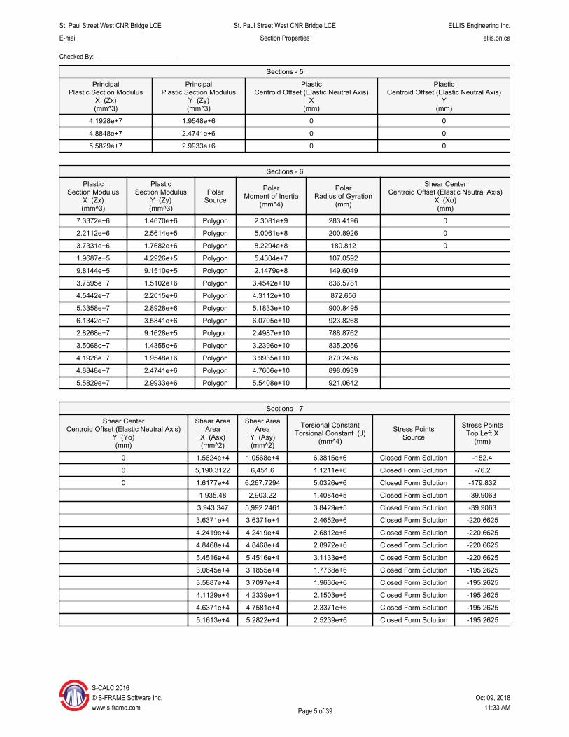
Sections - 5
Principal Plastic Section Modulus
X (Zx) (mm^3)
Principal Plastic Section Modulus
Y (Zy) (mm^3)
Plastic Centroid Offset (Elastic Neutral Axis)
X (mm)
Plastic Centroid Offset (Elastic Neutral Axis)
Y (mm)
4.1928e+7 1.9548e+6 0 0
4.8848e+7 2.4741e+6 0 0
5.5829e+7 2.9933e+6 0 0
Sections - 6
Plastic Section Modulus
X (Zx) (mm^3)
Plastic Section Modulus
Y (Zy) (mm^3)
Polar Source
Polar Moment of Inertia
(mm^4)
Polar Radius of Gyration
(mm)
Shear Center Centroid Offset (Elastic Neutral Axis)
X (Xo) (mm)
7.3372e+6 1.4670e+6 Polygon 2.3081e+9 283.4196 0
2.2112e+6 2.5614e+5 Polygon 5.0061e+8 200.8926 0
3.7331e+6 1.7682e+6 Polygon 8.2294e+8 180.812 0
1.9687e+5 4.2926e+5 Polygon 5.4304e+7 107.0592
9.8144e+5 9.1510e+5 Polygon 2.1479e+8 149.6049
3.7595e+7 1.5102e+6 Polygon 3.4542e+10 836.5781
4.5442e+7 2.2015e+6 Polygon 4.3112e+10 872.656
5.3358e+7 2.8928e+6 Polygon 5.1833e+10 900.8495
6.1342e+7 3.5841e+6 Polygon 6.0705e+10 923.8268
2.8268e+7 9.1628e+5 Polygon 2.4987e+10 788.8762
3.5068e+7 1.4355e+6 Polygon 3.2396e+10 835.2056
4.1928e+7 1.9548e+6 Polygon 3.9935e+10 870.2456
4.8848e+7 2.4741e+6 Polygon 4.7606e+10 898.0939
5.5829e+7 2.9933e+6 Polygon 5.5408e+10 921.0642
Sections - 7
Shear Center Centroid Offset (Elastic Neutral Axis)
Y (Yo) (mm)
Shear Area Area
X (Asx) (mm^2)
Shear Area Area
Y (Asy) (mm^2)
Torsional Constant Torsional Constant (J)
(mm^4)
Stress Points Source
Stress Points Top Left X
(mm)
0 1.5624e+4 1.0568e+4 6.3815e+6 Closed Form Solution -152.4
0 5,190.3122 6,451.6 1.1211e+6 Closed Form Solution -76.2
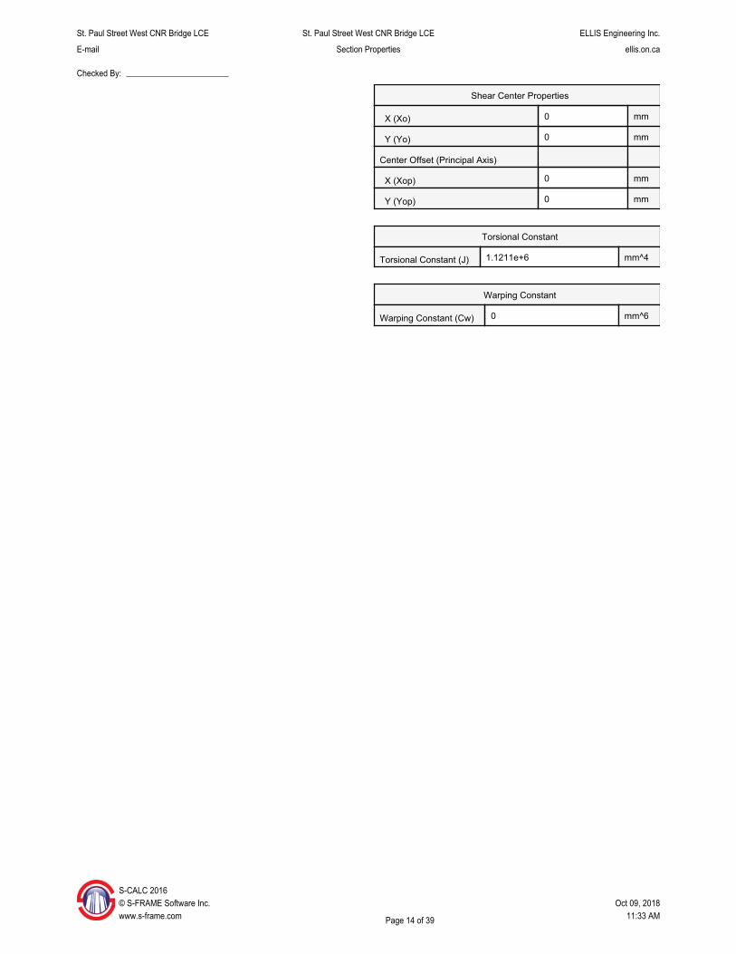
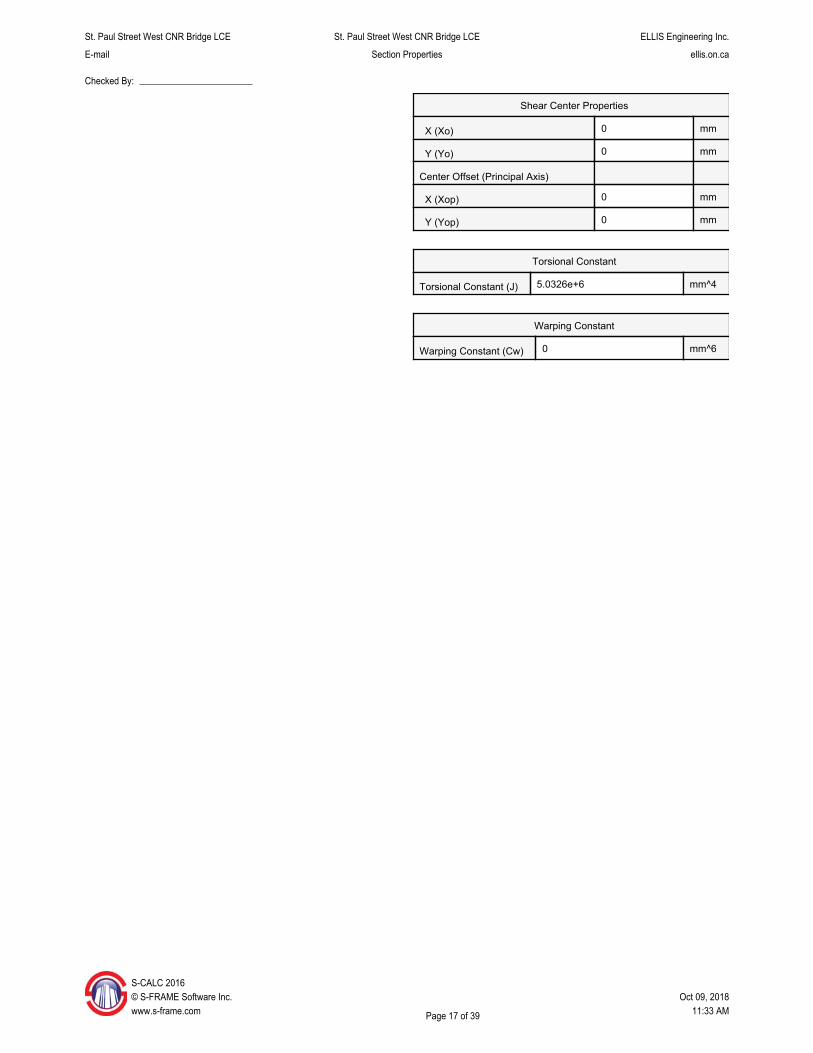
0 1.6177e+4 6,267.7294 5.0326e+6 Closed Form Solution -179.832
1,935.48 2,903.22 1.4084e+5 Closed Form Solution -39.9063
3,943.347 5,992.2461 3.8429e+5 Closed Form Solution -39.9063
3.6371e+4 3.6371e+4 2.4652e+6 Closed Form Solution -220.6625
4.2419e+4 4.2419e+4 2.6812e+6 Closed Form Solution -220.6625
4.8468e+4 4.8468e+4 2.8972e+6 Closed Form Solution -220.6625
5.4516e+4 5.4516e+4 3.1133e+6 Closed Form Solution -220.6625
3.0645e+4 3.1855e+4 1.7768e+6 Closed Form Solution -195.2625
3.5887e+4 3.7097e+4 1.9636e+6 Closed Form Solution -195.2625
4.1129e+4 4.2339e+4 2.1503e+6 Closed Form Solution -195.2625
4.6371e+4 4.7581e+4 2.3371e+6 Closed Form Solution -195.2625
5.1613e+4 5.2822e+4 2.5239e+6 Closed Form Solution -195.2625
S-CALC 2016 © S-FRAME Software Inc. Oct 09, 2018 www.s-frame.com Page 5 of 39 11:33 AM
St. Paul Street West CNR Bridge LCE St. Paul Street West CNR Bridge LCE ELLIS Engineering Inc.
E-mail Section Properties ellis.on.ca
Checked By:
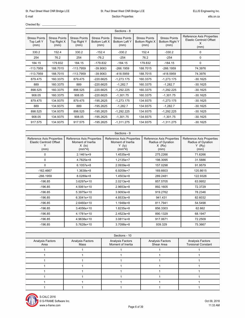
Sections - 8
Stress Points Top Left Y
(mm)
Stress Points Top Right X
(mm)
Stress Points Top Right Y
(mm)
Stress Points Bottom Left X
(mm)
Stress Points Bottom Left Y
(mm)
Stress Points Bottom Right X
(mm)
Stress Points Bottom Right Y
(mm)
Reference Axis Properties Elastic Centroid Offset
X (mm)
330.2 152.4 330.2 -152.4 -330.2 152.4 -330.2 0
254 76.2 254 -76.2 -254 76.2 -254 0
184.15 179.832 184.15 -179.832 -184.15 179.832 -184.15 0
-113.7959 188.7015 -113.7959 -39.9063 -266.1959 188.7015 -266.1959 74.3976
-113.7959 188.7015 -113.7959 -39.9063 -418.5959 188.7015 -418.5959 74.3976
879.475 160.3375 879.475 -220.6625 -1,273.175 160.3375 -1,273.175 -30.1625
889 160.3375 889 -220.6625 -1,282.7 160.3375 -1,282.7 -30.1625
898.525 160.3375 898.525 -220.6625 -1,292.225 160.3375 -1,292.225 -30.1625
908.05 160.3375 908.05 -220.6625 -1,301.75 160.3375 -1,301.75 -30.1625
879.475 134.9375 879.475 -195.2625 -1,273.175 134.9375 -1,273.175 -30.1625
889 134.9375 889 -195.2625 -1,282.7 134.9375 -1,282.7 -30.1625
898.525 134.9375 898.525 -195.2625 -1,292.225 134.9375 -1,292.225 -30.1625
908.05 134.9375 908.05 -195.2625 -1,301.75 134.9375 -1,301.75 -30.1625
917.575 134.9375 917.575 -195.2625 -1,311.275 134.9375 -1,311.275 -30.1625
Sections - 9
Reference Axis Properties Elastic Centroid Offset
Y (mm)
Reference Axis Properties Moment of Inertia
X (Ix) (mm^4)
Reference Axis Properties Moment of Inertia
Y (Iy) (mm^4)
Reference Axis Properties Radius of Gyration
X (Rx) (mm)
Reference Axis Properties Radius of Gyration
Y (Ry) (mm)
0 2.1461e+9 1.4535e+8 275.2266 71.6266
0 4.7825e+8 1.2135e+7 198.3095 31.5886
0 6.1057e+8 2.0939e+8 157.0298 91.9579
-162.4667 1.3638e+8 6.9209e+7 169.6603 120.8615
-266.1959 8.0289e+8 1.4503e+8 289.2481 122.9326
-196.85 3.6297e+10 2.0213e+8 857.5705 63.9952
-196.85 4.5061e+10 2.9653e+8 892.1605 72.3729
-196.85 5.3975e+10 3.9093e+8 919.2762 78.2346
-196.85 6.3041e+10 4.8533e+8 941.431 82.6032
-196.85 2.6460e+10 1.1948e+8 811.7941 54.5498
-196.85 3.4056e+10 1.8235e+8 856.3303 62.662
-196.85 4.1781e+10 2.4523e+8 890.1329 68.1947
-196.85 4.9638e+10 3.0811e+8 917.0671 72.2509
-196.85 5.7628e+10 3.7098e+8 939.329 75.3667
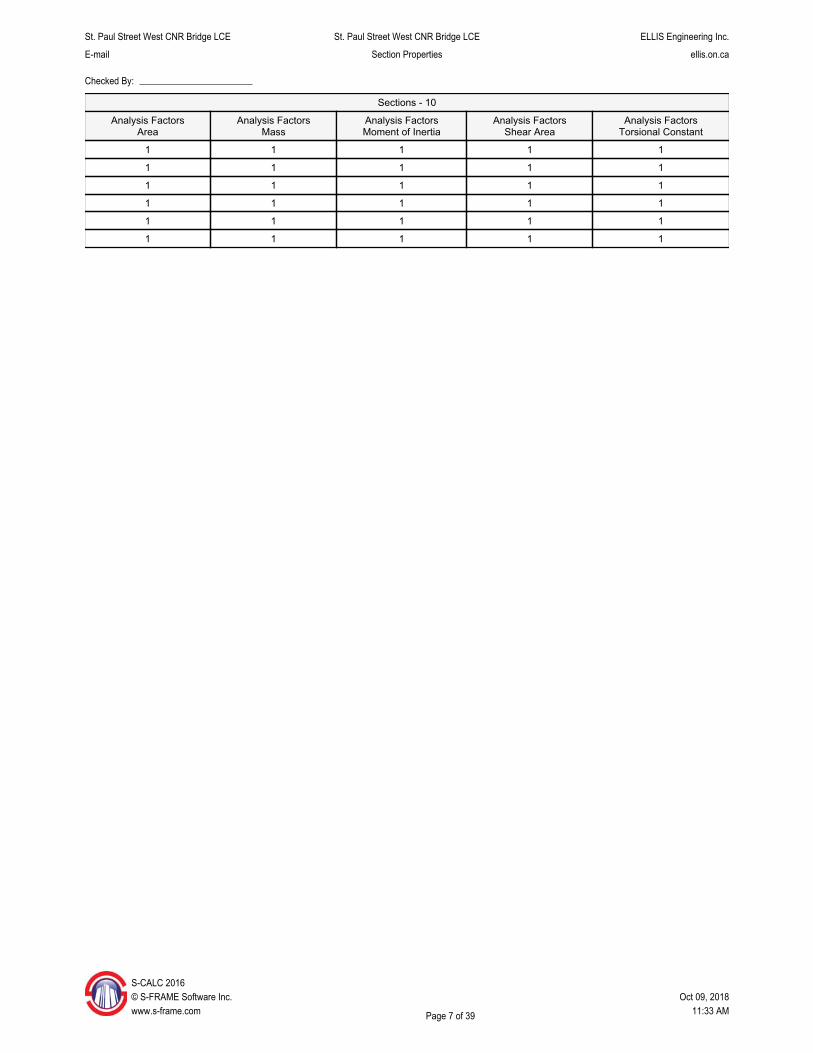
Sections - 10
Analysis Factors Area
Analysis Factors Mass
Analysis Factors Moment of Inertia
Analysis Factors Shear Area
Analysis Factors Torsional Constant
1 1 1 1 1
1 1 1 1 1
1 1 1 1 1
1 1 1 1 1
1 1 1 1 1
1 1 1 1 1
1 1 1 1 1
1 1 1 1 1
S-CALC 2016 © S-FRAME Software Inc. Oct 09, 2018 www.s-frame.com Page 6 of 39 11:33 AM
St. Paul Street West CNR Bridge LCE St. Paul Street West CNR Bridge LCE ELLIS Engineering Inc.
E-mail Section Properties ellis.on.ca
Checked By:
Sections - 10
Analysis Factors Area
Analysis Factors Mass
Analysis Factors Moment of Inertia
Analysis Factors Shear Area
Analysis Factors Torsional Constant
1 1 1 1 1
1 1 1 1 1
1 1 1 1 1
1 1 1 1 1
1 1 1 1 1
1 1 1 1 1
S-CALC 2016 © S-FRAME Software Inc. Oct 09, 2018 www.s-frame.com Page 7 of 39 11:33 AM
St. Paul Street West CNR Bridge LCE St. Paul Street West CNR Bridge LCE ELLIS Engineering Inc.
E-mail Section Properties ellis.on.ca
Checked By:
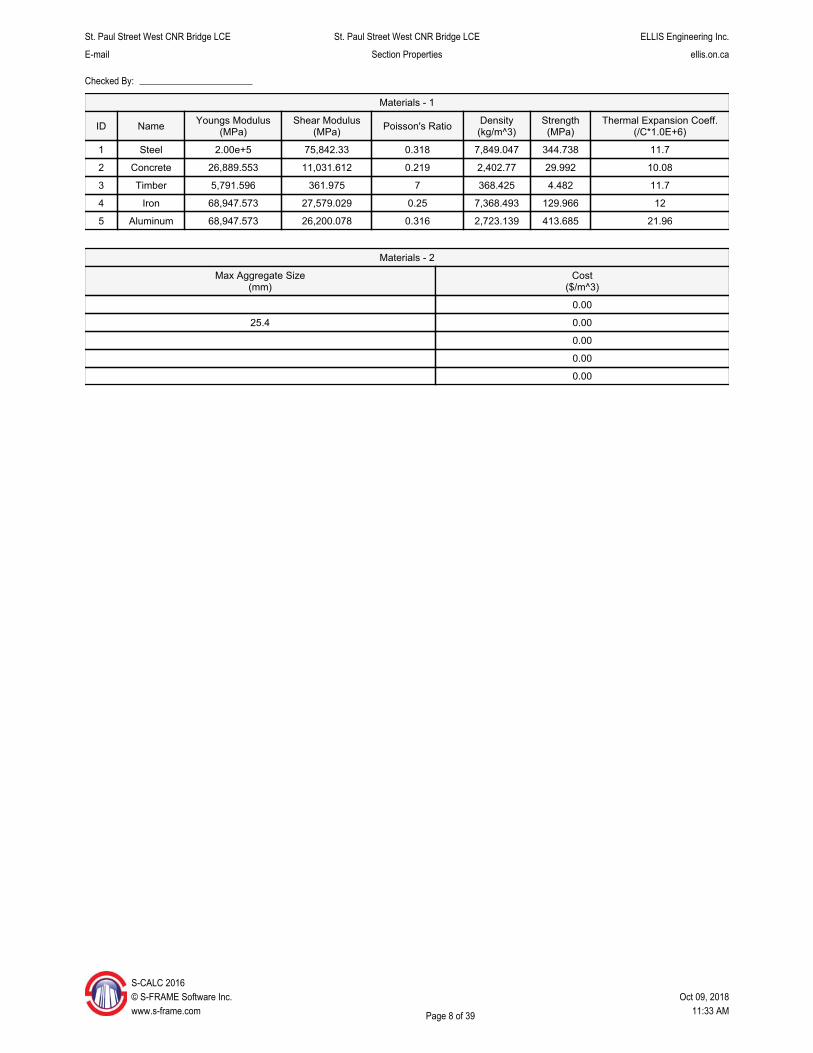
Materials - 1
ID Name Youngs Modulus (MPa)
Shear Modulus (MPa) Poisson's Ratio Density
(kg/m^3) Strength (MPa)
Thermal Expansion Coeff. (/C*1.0E+6)
1 Steel 2.00e+5 75,842.33 0.318 7,849.047 344.738 11.7
2 Concrete 26,889.553 11,031.612 0.219 2,402.77 29.992 10.08
3 Timber 5,791.596 361.975 7 368.425 4.482 11.7
4 Iron 68,947.573 27,579.029 0.25 7,368.493 129.966 12
5 Aluminum 68,947.573 26,200.078 0.316 2,723.139 413.685 21.96
Materials - 2
Max Aggregate Size (mm)
Cost ($/m^3)
0.00
25.4 0.00
0.00
0.00
0.00
S-CALC 2016 © S-FRAME Software Inc. Oct 09, 2018 www.s-frame.com Page 8 of 39 11:33 AM
St. Paul Street West CNR Bridge LCE St. Paul Street West CNR Bridge LCE ELLIS Engineering Inc.
E-mail Section Properties ellis.on.ca
Checked By:
Stringer (26"x150lb/ft)
S-CALC 2016 © S-FRAME Software Inc. Oct 09, 2018 www.s-frame.com Page 9 of 39 11:33 AM
St. Paul Street West CNR Bridge LCE St. Paul Street West CNR Bridge LCE ELLIS Engineering Inc.
E-mail Section Properties ellis.on.ca
Checked By:
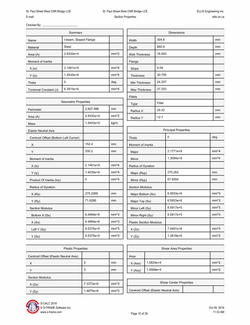
Summary
Name I-beam, Sloped Flange
Material Steel
Area (A) 2.8332e+4 mm^2
Moment of Inertia
X (Ix) 2.1461e+9 mm^4
Y (Iy) 1.4535e+8 mm^4
Theta 0 deg
Torsional Constant (J) 6.3815e+6 mm^4
Geometric Properties
Perimeter 2,507.996 mm
Area (A) 2.8332e+4 mm^2
Mass 1.5443e+9 kg/m
Elastic Neutral Axis
Centroid Offset (Bottom Left Corner)
X 152.4 mm
Y 330.2 mm
Moment of Inertia
X (Ix) 2.1461e+9 mm^4
Y (Iy) 1.4535e+8 mm^4
Product Of Inertia (Ixy) 0 mm^4
Radius of Gyration
X (Rx) 275.2266 mm
Y (Ry) 71.6266 mm
Section Modulus
Bottom X (Sx) 6.4994e+6 mm^3
X (Sx) 6.4994e+6 mm^3
Left Y (Sy) 9.5375e+5 mm^3
Y (Sy) 9.5375e+5 mm^3
Dimensions
Width 304.8 mm
Depth 660.4 mm
Web Thickness 16.002 mm
Flange
Slope 0.09
Thickness 30.755 mm
Min Thickness 24.257 mm
Max Thickness 37.253 mm
Fillets
Type Fillet
Radius X 20.32 mm
Radius Y 12.7 mm
Principal Properties
Theta 0 deg
Moment of Inertia
Major 2.1771e+9 mm^4
Minor 1.3094e+8 mm^4
Radius of Gyration
Major (Rxp) 275.263 mm
Minor (Ryp) 67.5054 mm
Section Modulus
Major Bottom (Sx) 6.5933e+6 mm^3
Major Top (Sx) 6.5933e+6 mm^3
Minor Left (Sy) 8.5917e+5 mm^3
Minor Right (Sy) 8.5917e+5 mm^3
Plastic Section Modulus
X (Zx) 7.4491e+6 mm^3
Y (Zy) 1.3818e+6 mm^3
Plastic Properties
Centroid Offset (Elastic Neutral Axis)
X 0 mm
Y 0 mm
Section Modulus
X (Zx) 7.3372e+6 mm^3
Y (Zy) 1.4670e+6 mm^3
Shear Area Properties
Area
X (Asx) 1.5624e+4 mm^2
Y (Asy) 1.0568e+4 mm^2
Shear Center Properties
Centroid Offset (Elastic Neutral Axis)
S-CALC 2016 © S-FRAME Software Inc. Oct 09, 2018 www.s-frame.com Page 10 of 39 11:33 AM

St. Paul Street West CNR Bridge LCE St. Paul Street West CNR Bridge LCE ELLIS Engineering Inc.
E-mail Section Properties ellis.on.ca
Checked By:
Shear Center Properties
X (Xo) 0 mm
Y (Yo) 0 mm
Center Offset (Principal Axis)
X (Xop) 0 mm
Y (Yop) 0 mm
Torsional Constant
Torsional Constant (J) 6.3815e+6 mm^4
Warping Constant
Warping Constant (Cw) 0 mm^6
S©w
-CALC 2016 S-FRAME Software Inc. Oct 09, 2018 ww.s-frame.com Page 11 of 39 11:33 AM
St. Paul Street West CNR Bridge LCE St. Paul Street West CNR Bridge LCE ELLIS Engineering Inc.
E-mail Section Properties ellis.on.ca
Checked By:
Overhang (20"x65lb/ft)
S-CALC 2016 © S-FRAME Software Inc. Oct 09, 2018 www.s-frame.com Page 12 of 39 11:33 AM

St. Paul Street West CNR Bridge LCE St. Paul Street West CNR Bridge LCE ELLIS Engineering Inc.
E-mail Section Properties ellis.on.ca
Checked By:
Summary
Name I-beam, Sloped Flange
Material Steel
Area (A) 1.2161e+4 mm^2
Moment of Inertia
X (Ix) 4.7825e+8 mm^4
Y (Iy) 1.2135e+7 mm^4
Theta 0 deg
Torsional Constant (J) 1.1211e+6 mm^4
Geometric Properties
Perimeter 1,600.2 mm
Area (A) 1.2161e+4 mm^2
Mass 6.6286e+8 kg/m
Elastic Neutral Axis
Centroid Offset (Bottom Left Corner)
X 76.2 mm
Y 254 mm
Moment of Inertia
X (Ix) 4.7825e+8 mm^4
Y (Iy) 1.2135e+7 mm^4
Product Of Inertia (Ixy) 0 mm^4
Radius of Gyration
X (Rx) 198.3095 mm
Y (Ry) 31.5886 mm
Section Modulus
Bottom X (Sx) 1.8829e+6 mm^3
X (Sx) 1.8829e+6 mm^3
Left Y (Sy) 1.5925e+5 mm^3
Y (Sy) 1.5925e+5 mm^3
Dimensions
Width 152.4 mm
Depth 508 mm
Web Thickness 12.7 mm
Flange
Slope 0.156
Thickness 20.434 mm
Min Thickness 14.986 mm
Max Thickness 25.883 mm
Fillets
Type Fillet
Radius X 16.002 mm
Radius Y 12.7 mm
Principal Properties
Theta 0 deg
Moment of Inertia
Major 4.8991e+8 mm^4
Minor 1.0700e+7 mm^4
Radius of Gyration
Major (Rxp) 198.7342 mm
Minor (Ryp) 29.3695 mm
Section Modulus
Major Bottom (Sx) 1.9288e+6 mm^3
Major Top (Sx) 1.9288e+6 mm^3
Minor Left (Sy) 1.4041e+5 mm^3
Minor Right (Sy) 1.4041e+5 mm^3
Plastic Section Modulus
X (Zx) 2.2645e+6 mm^3
Y (Zy) 2.4088e+5 mm^3
Plastic Properties
Centroid Offset (Elastic Neutral Axis)
X 0 mm
Y 0 mm
Section Modulus
X (Zx) 2.2112e+6 mm^3
Y (Zy) 2.5614e+5 mm^3
Shear Area Properties
Area
X (Asx) 5,190.3122 mm^2
Y (Asy) 6,451.6 mm^2
Shear Center Properties
Centroid Offset (Elastic Neutral Axis)
S-CALC 2016 © S-FRAME Software Inc. Oct 09, 2018 www.s-frame.com Page 13 of 39 11:33 AM
St. Paul Street West CNR Bridge LCE St. Paul Street West CNR Bridge LCE ELLIS Engineering Inc.
E-mail Section Properties ellis.on.ca
Checked By:
Shear Center Properties
X (Xo) 0 mm
Y (Yo) 0 mm
Center Offset (Principal Axis)
X (Xop) 0 mm
Y (Yop) 0 mm
Torsional Constant
Torsional Constant (J) 1.1211e+6 mm^4
Warping Constant
Warping Constant (Cw) 0 mm^6
S-CALC 2016 © S-FRAME Software Inc. Oct 09, 2018 www.s-frame.com Page 14 of 39 11:33 AM
St. Paul Street West CNR Bridge LCE St. Paul Street West CNR Bridge LCE ELLIS Engineering Inc.
E-mail Section Properties ellis.on.ca
Checked By:
Pier Column (14.5"x130.5lb/ft)
S-CALC 2016 © S-FRAME Software Inc. Oct 09, 2018 www.s-frame.com Page 15 of 39 11:33 AM

St. Paul Street West CNR Bridge LCE St. Paul Street West CNR Bridge LCE ELLIS Engineering Inc.
E-mail Section Properties ellis.on.ca
Checked By:
Summary
Name I-beam, Sloped Flange
Material Steel
Area (A) 2.4761e+4 mm^2
Moment of Inertia
X (Ix) 6.1057e+8 mm^4
Y (Iy) 2.0939e+8 mm^4
Theta 0 deg
Torsional Constant (J) 5.0326e+6 mm^4
Geometric Properties
Perimeter 2,141.22 mm
Area (A) 2.4761e+4 mm^2
Mass 1.3497e+9 kg/m
Elastic Neutral Axis
Centroid Offset (Bottom Left Corner)
X 179.832 mm
Y 184.15 mm
Moment of Inertia
X (Ix) 6.1057e+8 mm^4
Y (Iy) 2.0939e+8 mm^4
Product Of Inertia (Ixy) 0 mm^4
Radius of Gyration
X (Rx) 157.0298 mm
Y (Ry) 91.9579 mm
Section Modulus
Bottom X (Sx) 3.3156e+6 mm^3
X (Sx) 3.3156e+6 mm^3
Left Y (Sy) 1.1643e+6 mm^3
Y (Sy) 1.1643e+6 mm^3
Dimensions
Width 359.664 mm
Depth 368.3 mm
Web Thickness 17.018 mm
Flange
Slope 0.02
Thickness 26.986 mm
Min Thickness 25.273 mm
Max Thickness 28.699 mm
Fillets
Type Fillet
Radius X 20.32 mm
Radius Y 12.7 mm
Principal Properties
Theta 0 deg
Moment of Inertia
Major 6.1979e+8 mm^4
Minor 2.0316e+8 mm^4
Radius of Gyration
Major (Rxp) 156.9147 mm
Minor (Ryp) 89.8373 mm
Section Modulus
Major Bottom (Sx) 3.3657e+6 mm^3
Major Top (Sx) 3.3657e+6 mm^3
Minor Left (Sy) 1.1297e+6 mm^3
Minor Right (Sy) 1.1297e+6 mm^3
Plastic Section Modulus
X (Zx) 3.7946e+6 mm^3
Y (Zy) 1.7402e+6 mm^3
Plastic Properties
Centroid Offset (Elastic Neutral Axis)
X 0 mm
Y 0 mm
Section Modulus
X (Zx) 3.7331e+6 mm^3
Y (Zy) 1.7682e+6 mm^3
Shear Area Properties
Area
X (Asx) 1.6177e+4 mm^2
Y (Asy) 6,267.7294 mm^2
Shear Center Properties
Centroid Offset (Elastic Neutral Axis)
S-CALC 2016 © S-FRAME Software Inc. Oct 09, 2018 www.s-frame.com Page 16 of 39 11:33 AM
St. Paul Street West CNR Bridge LCE St. Paul Street West CNR Bridge LCE ELLIS Engineering Inc.
E-mail Section Properties ellis.on.ca
Checked By:
Shear Center Properties
X (Xo) 0 mm
Y (Yo) 0 mm
Center Offset (Principal Axis)
X (Xop) 0 mm
Y (Yop) 0 mm
Torsional Constant
Torsional Constant (J) 5.0326e+6 mm^4
Warping Constant
Warping Constant (Cw) 0 mm^6
S-CALC 2016 © S-FRAME Software Inc. Oct 09, 2018 www.s-frame.com Page 17 of 39 11:33 AM
St. Paul Street West CNR Bridge LCE St. Paul Street West CNR Bridge LCE ELLIS Engineering Inc.
E-mail Section Properties ellis.on.ca
Checked By:
Pier Diagonal (2-L6"x4"x3/8")
S©w
-CALC 2016 S-FRAME Software Inc. Oct 09, 2018 ww.s-frame.com Page 18 of 39 11:33 AM
X
St. Paul Street West CNR Bridge LCE St. Paul Street West CNR Bridge LCE ELLIS Engineering Inc.
E-mail Section Properties ellis.on.ca
Checked By:
Name
Reference Material
Area (A)
Moment of Inertia
X (Ix)
Y (Iy)
Theta
Torsional Constant (J)
Perimeter
Area (A)
Mass
Elastic Neutral Axis
Centroid Offset (Bottom Left Corner)
114.3039
Y 103.7292
Moment of Inertia
X (Ix) 1.1320e+7
Y (Iy) 4.2985e+7
Product Of Inertia (Ixy) 0
Radius of Gyration
X (Rx) 48.8792
Y (Ry) 95.2497
Section Modulus
Bottom X (Sx) 1.0913e+5
Top X (Sx) 2.3258e+5
Left Y (Sy) 3.7605e+5
Y (Sy) 3.7605e+5
Plastic Properties
Centroid Offset (Elastic Neutral Axis)
0
Y 20.628
Section Modulus
X (Zx) 1.9687e+5
Y (Zy) 4.2926e+5
S-CALC 2016 © S-FRAME Software Inc. www.s-frame.com
Summary
Compound
Steel
4,737.8938
1.1320e+7
4.2985e+7
-90
1.4084e+5
Geometric Properties
1,004.644
4,737.8938
2.5825e+8
mm^2
mm^4
mm^4
deg
mm^4
mm
mm^2
kg/m
mm
mm
mm^4
mm^4
mm^4
mm
mm
mm^3
mm^3
mm^3
mm^3
mm
mm
mm^3
mm^3
228.608Width
152.4Depth
Theta
Moment of Inertia
Major
Minor
Radius of Gyration
Major (Rxp)
Minor (Ryp)
Section Modulus
Major Bottom (Sx)
Major Top (Sx)
Minor Left (Sy)
Minor Right (Sy)
Plastic Section Modulus
X (Zx)
Y (Zy)
Shear Area Properties
Area
X (Asx) 1,935.48 mm^2
Y (Asy) 2,903.22 mm^2
Shear Center Properties
Centroid Offset (Elastic Neutral Axis)
X (Xo)
Y (Yo)
Center Offset (Principal Axis)
X (Xop)
Y (Yop)
Torsional Constant
1.4084e+5 mm^4Torsional Constant (J)
Warping Constant
0 mm^6Warping Constant (Cw)
Oct 09, 2018 11:33 AMPage 19 of 39
Dimensions
Principal Properties
mm
mm
0 mm
0 mm
0 mm
0 mm
-90
4.2985e+7
1.1320e+7
95.2497
48.8792
3.7605e+5
3.7605e+5
2.3258e+5
1.0913e+5
4.2926e+5
1.9687e+5
deg
mm^4
mm^4
mm
mm
mm^3
mm^3
mm^3
mm^3
mm^3
mm^3
X
St. Paul Street West CNR Bridge LCE St. Paul Street West CNR Bridge LCE ELLIS Engineering Inc.
E-mail Section Properties ellis.on.ca
Checked By:
Pier Strut (2-C12"x25lb/ft)
S-CALC 2016 © S-FRAME Software Inc. Oct 09, 2018 www.s-frame.com Page 20 of 39 11:33 AM

X
St. Paul Street West CNR Bridge LCE St. Paul Street West CNR Bridge LCE ELLIS Engineering Inc.
E-mail Section Properties ellis.on.ca
Checked By:
Name
Reference Material
Area (A)
Moment of Inertia
X (Ix)
Y (Iy)
Theta
Torsional Constant (J)
Perimeter
Area (A)
Mass
Elastic Neutral Axis
Centroid Offset (Bottom Left Corner)
Y
Moment of Inertia
X (Ix)
Y (Iy)
Product Of Inertia (Ixy)
Radius of Gyration
X (Rx)
Y (Ry)
Section Modulus
Bottom X (Sx)
X (Sx)
Left Y (Sy)
Y (Sy)
Plastic Properties
Centroid Offset (Elastic Neutral Axis)
0
Y 0
Section Modulus
X (Zx) 9.8144e+5
Y (Zy) 9.1510e+5
S-CALC 2016 © S-FRAME Software Inc. www.s-frame.com
Summary
Compound
Steel
9,596.5305
1.2288e+8
9.1910e+7
0
3.8429e+5
Geometric Properties
1,776.9288
9,596.5305
5.2308e+8
114.3039
152.4
1.2288e+8
9.1910e+7
0
113.1557
97.8643
8.0627e+5
8.0627e+5
8.0408e+5
8.0408e+5
mm^2
mm^4
mm^4
deg
mm^4
mm
mm^2
kg/m
mm
mm
mm^4
mm^4
mm^4
mm
mm
mm^3
mm^3
mm^3
mm^3
mm
mm
mm^3
mm^3
228.608Width
304.8Depth
Theta
Moment of Inertia
Major
Minor
Radius of Gyration
Major (Rxp)
Minor (Ryp)
Section Modulus
Major Bottom (Sx)
Major Top (Sx)
Minor Left (Sy)
Minor Right (Sy)
Plastic Section Modulus
X (Zx)
Y (Zy)
Shear Area Properties
Area
X (Asx) 3,943.347 mm^2
Y (Asy) 5,992.2461 mm^2
Shear Center Properties
Centroid Offset (Elastic Neutral Axis)
X (Xo)
Y (Yo)
Center Offset (Principal Axis)
X (Xop)
Y (Yop)
Torsional Constant
3.8429e+5 mm^4Torsional Constant (J)
Warping Constant
0 mm^6Warping Constant (Cw)
Oct 09, 2018 11:33 AMPage 21 of 39
0 mm
0 mm
0 mm
0 mm
Dimensions
Principal Properties
0
1.2288e+8
9.1910e+7
113.1557
97.8643
8.0627e+5
8.0627e+5
8.0408e+5
8.0408e+5
9.8144e+5
9.1510e+5
mm
mm
deg
mm^4
mm^4
mm
mm
mm^3
mm^3
mm^3
mm^3
mm^3
mm^3
X
St. Paul Street West CNR Bridge LCE St. Paul Street West CNR Bridge LCE ELLIS Engineering Inc.
E-mail Section Properties ellis.on.ca
Checked By:
Main Girder (15" x 1 Plate)
S-CALC 2016 © S-FRAME Software Inc. Oct 09, 2018 www.s-frame.com Page 22 of 39 11:33 AM

X
St. Paul Street West CNR Bridge LCE St. Paul Street West CNR Bridge LCE ELLIS Engineering Inc.
E-mail Section Properties ellis.on.ca
Checked By:
Name
Reference Material
Area (A)
Moment of Inertia
X (Ix)
Y (Iy)
Theta
Torsional Constant (J)
Perimeter
Area (A)
Mass
Elastic Neutral Axis
Centroid Offset (Bottom Left Corner)
1,076.325
Moment of Inertia
X (Ix) 3.4384e+10
Y (Iy) 1.5723e+8
Product Of Inertia (Ixy) 0
Radius of Gyration
X (Rx) 834.6719
Y (Ry) 56.4412
Section Modulus
Bottom X (Sx) 3.1946e+7
X (Sx) 3.1946e+7
Left Y (Sy) 8.2533e+5
Y (Sy) 8.2533e+5
Plastic Properties
Centroid Offset (Elastic Neutral Axis)
0
Y 0
Section Modulus
X (Zx) 3.7595e+7
Y (Zy) 1.5102e+6
S-CALC 2016 © S-FRAME Software Inc. www.s-frame.com
Summary
Compound
Steel
4.9355e+4
3.4384e+10
1.5723e+8
0
2.4652e+6
Geometric Properties
8,270.388
4.9355e+4
2.6902e+9
mm^2
mm^4
mm^4
deg
mm^4
mm
mm^2
kg/m
mm
mm
mm^4
mm^4
mm^4
mm
mm
mm^3
mm^3
mm^3
mm^3
mm
mm
mm^3
mm^3
381Width
2,152.65Depth
Theta
Moment of Inertia
Major
Minor
Radius of Gyration
Major (Rxp)
Minor (Ryp)
Section Modulus
Major Bottom (Sx)
Major Top (Sx)
Minor Left (Sy)
Minor Right (Sy)
Plastic Section Modulus
X (Zx)
Y (Zy)
Shear Area Properties
Area
X (Asx) 3.6371e+4 mm^2
Y (Asy) 3.6371e+4 mm^2
Shear Center Properties
Centroid Offset (Elastic Neutral Axis)
X (Xo)
Y (Yo)
Center Offset (Principal Axis)
X (Xop)
Y (Yop)
Torsional Constant
2.4652e+6 mm^4Torsional Constant (J)
Warping Constant
0 mm^6Warping Constant (Cw)
Oct 09, 2018 11:33 AMPage 23 of 39
Dimensions
Principal Properties
mm
mm
0 mm
0 mm
0 mm
0 mm
0
3.4384e+10
1.5723e+8
834.6719
56.4412
3.1946e+7
3.1946e+7
8.2533e+5
8.2533e+5
3.7595e+7
1.5102e+6
deg
mm^4
mm^4
mm
mm
mm^3
mm^3
mm^3
mm^3
mm^3
mm^3
X

St. Paul Street West CNR Bridge LCE St. Paul Street West CNR Bridge LCE ELLIS Engineering Inc.
E-mail Section Properties ellis.on.ca
Checked By:
Main Girder (15" x 2 Plates)
S-© w
CALC 2016 S-FRAME Software Inc. Oct 09, 2018
ww.s-frame.com Page 24 of 39 11:33 AM
X
St. Paul Street West CNR Bridge LCE St. Paul Street West CNR Bridge LCE ELLIS Engineering Inc.
E-mail Section Properties ellis.on.ca
Checked By:
Name
Reference Material
Area (A)
Moment of Inertia
X (Ix)
Y (Iy)
Theta
Torsional Constant (J)
Perimeter
Area (A)
Mass
Elastic Neutral Axis
Centroid Offset (Bottom Left Corner)
190.5
Y 1,085.85
Moment of Inertia
X (Ix) 4.2867e+10
Y (Iy) 2.4502e+8
Product Of Inertia (Ixy) 0
Radius of Gyration
X (Rx) 870.1726
Y (Ry) 65.788
Section Modulus
Bottom X (Sx) 3.9478e+7
X (Sx) 3.9478e+7
Left Y (Sy) 1.2862e+6
Y (Sy) 1.2862e+6
Plastic Properties
Centroid Offset (Elastic Neutral Axis)
0
Y 0
Section Modulus
X (Zx) 4.5442e+7
Y (Zy) 2.2015e+6
S-CALC 2016 © S-FRAME Software Inc. www.s-frame.com
Summary
Compound
Steel
5.6613e+4
4.2867e+10
2.4502e+8
0
2.6812e+6
Geometric Properties
9,832.488
5.6613e+4
3.0858e+9
mm^2
mm^4
mm^4
deg
mm^4
mm
mm^2
kg/m
mm
mm
mm^4
mm^4
mm^4
mm
mm
mm^3
mm^3
mm^3
mm^3
mm
mm
mm^3
mm^3
381Width
2,171.7Depth
Theta
Moment of Inertia
Major
Minor
Radius of Gyration
Major (Rxp)
Minor (Ryp)
Section Modulus
Major Bottom (Sx)
Major Top (Sx)
Minor Left (Sy)
Minor Right (Sy)
Plastic Section Modulus
X (Zx)
Y (Zy)
Shear Area Properties
Area
X (Asx) 4.2419e+4 mm^2
Y (Asy) 4.2419e+4 mm^2
Shear Center Properties
Centroid Offset (Elastic Neutral Axis)
X (Xo)
Y (Yo)
Center Offset (Principal Axis)
X (Xop)
Y (Yop)
Torsional Constant
2.6812e+6 mm^4Torsional Constant (J)
Warping Constant
0 mm^6Warping Constant (Cw)
Oct 09, 2018 11:33 AMPage 25 of 39
Dimensions
Principal Properties
mm
mm
0 mm
0 mm
0 mm
0 mm
0
4.2867e+10
2.4502e+8
870.1726
65.788
3.9478e+7
3.9478e+7
1.2862e+6
1.2862e+6
4.5442e+7
2.2015e+6
deg
mm^4
mm^4
mm
mm
mm^3
mm^3
mm^3
mm^3
mm^3
mm^3
X
St. Paul Street West CNR Bridge LCE St. Paul Street West CNR Bridge LCE ELLIS Engineering Inc.
E-mail Section Properties ellis.on.ca
Checked By:
Main Girder (15" x 3 Plates)
S-CALC 2016 © S-FRAME Software Inc. Oct 09, 2018 www.s-frame.com Page 26 of 39 11:33 AM

S-© w
X
St. Paul Street West CNR Bridge LCE St. Paul Street West CNR Bridge LCE ELLIS Engineering Inc.
E-mail Section Properties ellis.on.ca
Checked By:
Name
Reference Material
Area (A)
Moment of Inertia
X (Ix)
Y (Iy)
Theta
Torsional Constant (J)
Perimeter
Area (A)
Mass
Elastic Neutral Axis
Centroid Offset (Bottom Left Corner)
190.5
Y 1,095.375
Moment of Inertia
X (Ix) 5.1500e+10
Y (Iy) 3.3282e+8
Product Of Inertia (Ixy) 0
Radius of Gyration
X (Rx) 897.9526
Y (Ry) 72.1864
Section Modulus
Bottom X (Sx) 4.7016e+7
X (Sx) 4.7016e+7
Left Y (Sy) 1.7471e+6
Y (Sy) 1.7471e+6
Plastic Properties
Centroid Offset (Elastic Neutral Axis)
0
Y 0
Section Modulus
X (Zx) 5.3358e+7
Y (Zy) 2.8928e+6
CALC 2016 S-FRAME Software Inc.
ww.s-frame.com
Summary
Compound
Steel
6.3871e+4
5.1500e+10
3.3282e+8
0
2.8972e+6
Geometric Properties
1.1395e+4
6.3871e+4
3.4814e+9
mm^2
mm^4
mm^4
deg
mm^4
mm
mm^2
kg/m
mm
mm
mm^4
mm^4
mm^4
mm
mm
mm^3
mm^3
mm^3
mm^3
mm
mm
mm^3
mm^3
381Width
2,190.75Depth
Theta
Moment of Inertia
Major
Minor
Radius of Gyration
Major (Rxp)
Minor (Ryp)
Section Modulus
Major Bottom (Sx)
Major Top (Sx)
Minor Left (Sy)
Minor Right (Sy)
Plastic Section Modulus
X (Zx)
Y (Zy)
Shear Area Properties
Area
X (Asx) 4.8468e+4 mm^2
Y (Asy) 4.8468e+4 mm^2
Shear Center Properties
Centroid Offset (Elastic Neutral Axis)
X (Xo)
Y (Yo)
Center Offset (Principal Axis)
X (Xop)
Y (Yop)
Torsional Constant
2.8972e+6 mm^4Torsional Constant (J)
Warping Constant
0 mm^6Warping Constant (Cw)
Oct 09, 2018 11:33 AMPage 27 of 39
Dimensions
Principal Properties
mm
mm
0 mm
0 mm
0 mm
0 mm
0
5.1500e+10
3.3282e+8
897.9526
72.1864
4.7016e+7
4.7016e+7
1.7471e+6
1.7471e+6
5.3358e+7
2.8928e+6
deg
mm^4
mm^4
mm
mm
mm^3
mm^3
mm^3
mm^3
mm^3
mm^3
X

St. Paul Street West CNR Bridge LCE St. Paul Street West CNR Bridge LCE ELLIS Engineering Inc.
E-mail Section Properties ellis.on.ca
Checked By:
Main Girder (15" x 4 Plates)
S-CALC 2016 © S-FRAME Software Inc. Oct 09, 2018 www.s-frame.com Page 28 of 39 11:33 AM

S©w
X
St. Paul Street West CNR Bridge LCE St. Paul Street West CNR Bridge LCE ELLIS Engineering Inc.
E-mail Section Properties ellis.on.ca
Checked By:
Name
Reference Material
Area (A)
Moment of Inertia
X (Ix)
Y (Iy)
Theta
Torsional Constant (J)
Perimeter
Area (A)
Mass
Elastic Neutral Axis
Centroid Offset (Bottom Left Corner)
190.5
Y 1,104.9
Moment of Inertia
X (Ix) 6.0285e+10
Y (Iy) 4.2062e+8
Product Of Inertia (Ixy) 0
Radius of Gyration
X (Rx) 920.6207
Y (Ry) 76.8994
Section Modulus
Bottom X (Sx) 5.4561e+7
X (Sx) 5.4561e+7
Left Y (Sy) 2.2080e+6
Y (Sy) 2.2080e+6
Plastic Properties
Centroid Offset (Elastic Neutral Axis)
0
Y 0
Section Modulus
X (Zx) 6.1342e+7
Y (Zy) 3.5841e+6
-CALC 2016 S-FRAME Software Inc. ww.s-frame.com
Summary
Compound
Steel
7.1129e+4
6.0285e+10
4.2062e+8
0
3.1133e+6
Geometric Properties
1.2957e+4
7.1129e+4
3.8770e+9
mm^2
mm^4
mm^4
deg
mm^4
mm
mm^2
kg/m
mm
mm
mm^4
mm^4
mm^4
mm
mm
mm^3
mm^3
mm^3
mm^3
mm
mm
mm^3
mm^3
381Width
2,209.8Depth
Theta
Moment of Inertia
Major
Minor
Radius of Gyration
Major (Rxp)
Minor (Ryp)
Section Modulus
Major Bottom (Sx)
Major Top (Sx)
Minor Left (Sy)
Minor Right (Sy)
Plastic Section Modulus
X (Zx)
Y (Zy)
Shear Area Properties
Area
X (Asx) 5.4516e+4 mm^2
Y (Asy) 5.4516e+4 mm^2
Shear Center Properties
Centroid Offset (Elastic Neutral Axis)
X (Xo)
Y (Yo)
Center Offset (Principal Axis)
X (Xop)
Y (Yop)
Torsional Constant
3.1133e+6 mm^4Torsional Constant (J)
Warping Constant
0 mm^6Warping Constant (Cw)
Oct 09, 2018 11:33 AMPage 29 of 39
Dimensions
Principal Properties
mm
mm
0 mm
0 mm
0 mm
0 mm
0
6.0285e+10
4.2062e+8
920.6207
76.8994
5.4561e+7
5.4561e+7
2.2080e+6
2.2080e+6
6.1342e+7
3.5841e+6
deg
mm^4
mm^4
mm
mm
mm^3
mm^3
mm^3
mm^3
mm^3
mm^3
X

St. Paul Street West CNR Bridge LCE St. Paul Street West CNR Bridge LCE ELLIS Engineering Inc.
E-mail Section Properties ellis.on.ca
Checked By:
Main Girder (13" x 1 Plate)
S-CALC 2016 © S-FRAME Software Inc. Oct 09, 2018 www.s-frame.com Page 30 of 39 11:33 AM
X
St. Paul Street West CNR Bridge LCE St. Paul Street West CNR Bridge LCE ELLIS Engineering Inc.
E-mail Section Properties ellis.on.ca
Checked By:
Name
Reference Material
Area (A)
Moment of Inertia
X (Ix)
Y (Iy)
Theta
Torsional Constant (J)
Perimeter
Area (A)
Mass
Elastic Neutral Axis
Centroid Offset (Bottom Left Corner)
165.1
Y 1,076.325
Moment of Inertia
X (Ix) 2.4904e+10
Y (Iy) 8.2948e+7
Product Of Inertia (Ixy) 0
Radius of Gyration
X (Rx) 787.5657
Y (Ry) 45.4522
Section Modulus
Bottom X (Sx) 2.3138e+7
X (Sx) 2.3138e+7
Left Y (Sy) 5.0241e+5
Y (Sy) 5.0241e+5
Plastic Properties
Centroid Offset (Elastic Neutral Axis)
0
Y 0
Section Modulus
X (Zx) 2.8268e+7
Y (Zy) 9.1628e+5
S-CALC 2016 © S-FRAME Software Inc. www.s-frame.com
Summary
Compound
Steel
4.0151e+4
2.4904e+10
8.2948e+7
0
1.7768e+6
Geometric Properties
7,355.988
4.0151e+4
2.1885e+9
mm^2
mm^4
mm^4
deg
mm^4
mm
mm^2
kg/m
mm
mm
mm^4
mm^4
mm^4
mm
mm
mm^3
mm^3
mm^3
mm^3
mm
mm
mm^3
mm^3
330.2Width
2,152.65Depth
Theta
Moment of Inertia
Major
Minor
Radius of Gyration
Major (Rxp)
Minor (Ryp)
Section Modulus
Major Bottom (Sx)
Major Top (Sx)
Minor Left (Sy)
Minor Right (Sy)
Plastic Section Modulus
X (Zx)
Y (Zy)
Shear Area Properties
Area
X (Asx) 3.0645e+4 mm^2
Y (Asy) 3.1855e+4 mm^2
Shear Center Properties
Centroid Offset (Elastic Neutral Axis)
X (Xo)
Y (Yo)
Center Offset (Principal Axis)
X (Xop)
Y (Yop)
Torsional Constant
1.7768e+6 mm^4Torsional Constant (J)
Warping Constant
0 mm^6Warping Constant (Cw)
Oct 09, 2018 11:33 AMPage 31 of 39
Dimensions
Principal Properties
mm
mm
0 mm
0 mm
0 mm
0 mm
0
2.4904e+10
8.2948e+7
787.5657
45.4522
2.3138e+7
2.3138e+7
5.0241e+5
5.0241e+5
2.8268e+7
9.1628e+5
deg
mm^4
mm^4
mm
mm
mm^3
mm^3
mm^3
mm^3
mm^3
mm^3
X

St. Paul Street West CNR Bridge LCE St. Paul Street West CNR Bridge LCE ELLIS Engineering Inc.
E-mail Section Properties ellis.on.ca
Checked By:
Main Girder (13" x 2 Plates)
S-CALC 2016 © S-FRAME Software Inc. Oct 09, 2018 www.s-frame.com Page 32 of 39 11:33 AM

X
St. Paul Street West CNR Bridge LCE St. Paul Street West CNR Bridge LCE ELLIS Engineering Inc.
E-mail Section Properties ellis.on.ca
Checked By:
Name
Reference Material
Area (A)
Moment of Inertia
X (Ix)
Y (Iy)
Theta
Torsional Constant (J)
Perimeter
Area (A)
Mass
Elastic Neutral Axis
Centroid Offset (Bottom Left Corner)
165.1
Y 1,085.85
Moment of Inertia
X (Ix) 3.2256e+10
Y (Iy) 1.4010e+8
Product Of Inertia (Ixy) 0
Radius of Gyration
X (Rx) 833.3976
Y (Ry) 54.9249
Section Modulus
Bottom X (Sx) 2.9706e+7
X (Sx) 2.9706e+7
Left Y (Sy) 8.4859e+5
Y (Sy) 8.4859e+5
Plastic Properties
Centroid Offset (Elastic Neutral Axis)
0
Y 0
Section Modulus
X (Zx) 3.5068e+7
Y (Zy) 1.4355e+6
S-CALC 2016 © S-FRAME Software Inc. www.s-frame.com
Summary
Compound
Steel
4.6441e+4
3.2256e+10
1.4010e+8
0
1.9636e+6
Geometric Properties
8,714.888
4.6441e+4
2.5314e+9
mm^2
mm^4
mm^4
deg
mm^4
mm
mm^2
kg/m
mm
mm
mm^4
mm^4
mm^4
mm
mm
mm^3
mm^3
mm^3
mm^3
mm
mm
mm^3
mm^3
330.2Width
2,171.7Depth
Theta
Moment of Inertia
Major
Minor
Radius of Gyration
Major (Rxp)
Minor (Ryp)
Section Modulus
Major Bottom (Sx)
Major Top (Sx)
Minor Left (Sy)
Minor Right (Sy)
Plastic Section Modulus
X (Zx)
Y (Zy)
Shear Area Properties
Area
X (Asx) 3.5887e+4 mm^2
Y (Asy) 3.7097e+4 mm^2
Shear Center Properties
Centroid Offset (Elastic Neutral Axis)
X (Xo)
Y (Yo)
Center Offset (Principal Axis)
X (Xop)
Y (Yop)
Torsional Constant
1.9636e+6 mm^4Torsional Constant (J)
Warping Constant
0 mm^6Warping Constant (Cw)
Oct 09, 2018 11:33 AMPage 33 of 39
Dimensions
Principal Properties
mm
mm
0 mm
0 mm
0 mm
0 mm
0
3.2256e+10
1.4010e+8
833.3976
54.9249
2.9706e+7
2.9706e+7
8.4859e+5
8.4859e+5
3.5068e+7
1.4355e+6
deg
mm^4
mm^4
mm
mm
mm^3
mm^3
mm^3
mm^3
mm^3
mm^3
X

St. Paul Street West CNR Bridge LCE St. Paul Street West CNR Bridge LCE ELLIS Engineering Inc.
E-mail Section Properties ellis.on.ca
Checked By:
Main Girder (13" x 3 Plates)
S-© w
CALC 2016 S-FRAME Software Inc. Oct 09, 2018
ww.s-frame.com Page 34 of 39 11:33 AM
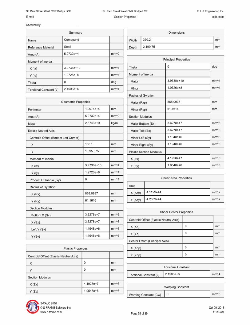
X
St. Paul Street West CNR Bridge LCE St. Paul Street West CNR Bridge LCE ELLIS Engineering Inc.
E-mail Section Properties ellis.on.ca
Checked By:
Name
Reference Material
Area (A)
Moment of Inertia
X (Ix)
Y (Iy)
Theta
Torsional Constant (J)
Perimeter
Area (A)
Mass
Elastic Neutral Axis
Centroid Offset (Bottom Left Corner)
165.1
Y 1,095.375
Moment of Inertia
X (Ix) 3.9738e+10
Y (Iy) 1.9726e+8
Product Of Inertia (Ixy) 0
Radius of Gyration
X (Rx) 868.0937
Y (Ry) 61.1616
Section Modulus
Bottom X (Sx) 3.6278e+7
X (Sx) 3.6278e+7
Left Y (Sy) 1.1948e+6
Y (Sy) 1.1948e+6
Plastic Properties
Centroid Offset (Elastic Neutral Axis)
0
Y 0
Section Modulus
X (Zx) 4.1928e+7
Y (Zy) 1.9548e+6
S-CALC 2016 © S-FRAME Software Inc. www.s-frame.com
Summary
Compound
Steel
5.2732e+4
3.9738e+10
1.9726e+8
0
2.1503e+6
Geometric Properties
1.0074e+4
5.2732e+4
2.8743e+9
mm^2
mm^4
mm^4
deg
mm^4
mm
mm^2
kg/m
mm
mm
mm^4
mm^4
mm^4
mm
mm
mm^3
mm^3
mm^3
mm^3
mm
mm
mm^3
mm^3
330.2Width
2,190.75Depth
Theta
Moment of Inertia
Major
Minor
Radius of Gyration
Major (Rxp)
Minor (Ryp)
Section Modulus
Major Bottom (Sx)
Major Top (Sx)
Minor Left (Sy)
Minor Right (Sy)
Plastic Section Modulus
X (Zx)
Y (Zy)
Shear Area Properties
Area
X (Asx) 4.1129e+4 mm^2
Y (Asy) 4.2339e+4 mm^2
Shear Center Properties
Centroid Offset (Elastic Neutral Axis)
X (Xo)
Y (Yo)
Center Offset (Principal Axis)
X (Xop)
Y (Yop)
Torsional Constant
2.1503e+6 mm^4Torsional Constant (J)
Warping Constant
0 mm^6Warping Constant (Cw)
Oct 09, 2018 11:33 AMPage 35 of 39
Dimensions
Principal Properties
mm
mm
0 mm
0 mm
0 mm
0 mm
0
3.9738e+10
1.9726e+8
868.0937
61.1616
3.6278e+7
3.6278e+7
1.1948e+6
1.1948e+6
4.1928e+7
1.9548e+6
deg
mm^4
mm^4
mm
mm
mm^3
mm^3
mm^3
mm^3
mm^3
mm^3
X

St. Paul Street West CNR Bridge LCE St. Paul Street West CNR Bridge LCE ELLIS Engineering Inc.
E-mail Section Properties ellis.on.ca
Checked By:
Main Girder (13" x 4 Plates)
S-CALC 2016 © S-FRAME Software Inc. Oct 09, 2018 www.s-frame.com Page 36 of 39 11:33 AM
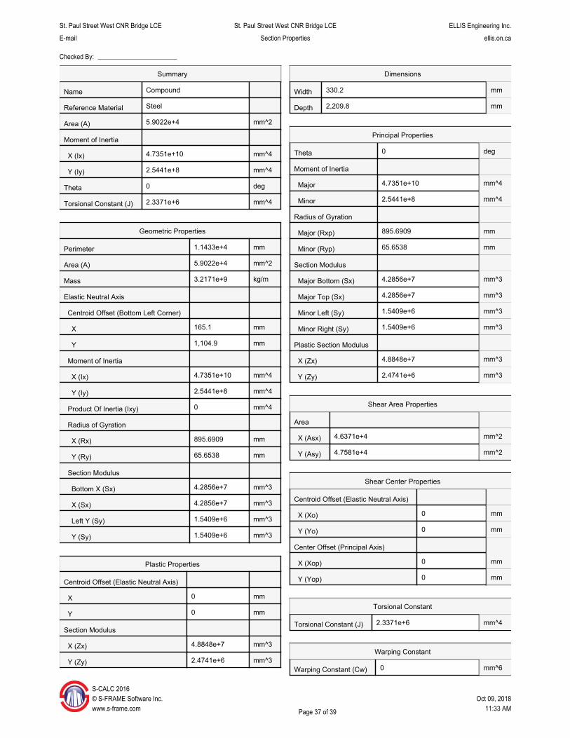
S-© w
X
St. Paul Street West CNR Bridge LCE St. Paul Street West CNR Bridge LCE ELLIS Engineering Inc.
E-mail Section Properties ellis.on.ca
Checked By:
Name
Reference Material
Area (A)
Moment of Inertia
X (Ix)
Y (Iy)
Theta
Torsional Constant (J)
Perimeter
Area (A)
Mass
Elastic Neutral Axis
Centroid Offset (Bottom Left Corner)
165.1
Y 1,104.9
Moment of Inertia
X (Ix) 4.7351e+10
Y (Iy) 2.5441e+8
Product Of Inertia (Ixy) 0
Radius of Gyration
X (Rx) 895.6909
Y (Ry) 65.6538
Section Modulus
Bottom X (Sx) 4.2856e+7
X (Sx) 4.2856e+7
Left Y (Sy) 1.5409e+6
Y (Sy) 1.5409e+6
Plastic Properties
Centroid Offset (Elastic Neutral Axis)
0
Y 0
Section Modulus
X (Zx) 4.8848e+7
Y (Zy) 2.4741e+6
CALC 2016 S-FRAME Software Inc.
ww.s-frame.com
Summary
Compound
Steel
5.9022e+4
4.7351e+10
2.5441e+8
0
2.3371e+6
Geometric Properties
1.1433e+4
5.9022e+4
3.2171e+9
mm^2
mm^4
mm^4
deg
mm^4
mm
mm^2
kg/m
mm
mm
mm^4
mm^4
mm^4
mm
mm
mm^3
mm^3
mm^3
mm^3
mm
mm
mm^3
mm^3
330.2Width
2,209.8Depth
Theta
Moment of Inertia
Major
Minor
Radius of Gyration
Major (Rxp)
Minor (Ryp)
Section Modulus
Major Bottom (Sx)
Major Top (Sx)
Minor Left (Sy)
Minor Right (Sy)
Plastic Section Modulus
X (Zx)
Y (Zy)
Shear Area Properties
Area
X (Asx) 4.6371e+4 mm^2
Y (Asy) 4.7581e+4 mm^2
Shear Center Properties
Centroid Offset (Elastic Neutral Axis)
X (Xo)
Y (Yo)
Center Offset (Principal Axis)
X (Xop)
Y (Yop)
Torsional Constant
2.3371e+6 mm^4Torsional Constant (J)
Warping Constant
0 mm^6Warping Constant (Cw)
Oct 09, 2018 11:33 AMPage 37 of 39
Dimensions
Principal Properties
mm
mm
0 mm
0 mm
0 mm
0 mm
0
4.7351e+10
2.5441e+8
895.6909
65.6538
4.2856e+7
4.2856e+7
1.5409e+6
1.5409e+6
4.8848e+7
2.4741e+6
deg
mm^4
mm^4
mm
mm
mm^3
mm^3
mm^3
mm^3
mm^3
mm^3
X
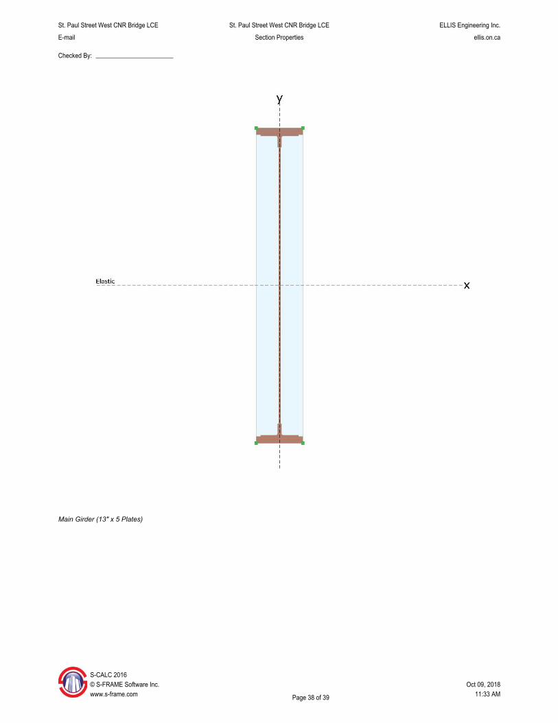
St. Paul Street West CNR Bridge LCE St. Paul Street West CNR Bridge LCE ELLIS Engineering Inc.
E-mail Section Properties ellis.on.ca
Checked By:
Main Girder (13" x 5 Plates)
S©w
-CALC 2016 S-FRAME Software Inc. Oct 09, 2018 ww.s-frame.com Page 38 of 39 11:33 AM

S©w
X
St. Paul Street West CNR Bridge LCE St. Paul Street West CNR Bridge LCE ELLIS Engineering Inc.
E-mail Section Properties ellis.on.ca
Checked By:
Name
Reference Material
Area (A)
Moment of Inertia
X (Ix)
Y (Iy)
Theta
Torsional Constant (J)
Perimeter
Area (A)
Mass
Elastic Neutral Axis
Centroid Offset (Bottom Left Corner)
165.1
Y 1,114.425
Moment of Inertia
X (Ix) 5.5097e+10
Y (Iy) 3.1156e+8
Product Of Inertia (Ixy) 0
Radius of Gyration
X (Rx) 918.471
Y (Ry) 69.0678
Section Modulus
Bottom X (Sx) 4.9440e+7
X (Sx) 4.9440e+7
Left Y (Sy) 1.8871e+6
Y (Sy) 1.8871e+6
Plastic Properties
Centroid Offset (Elastic Neutral Axis)
0
Y 0
Section Modulus
X (Zx) 5.5829e+7
Y (Zy) 2.9933e+6
-CALC 2016 S-FRAME Software Inc. ww.s-frame.com
Summary
Compound
Steel
6.5312e+4
5.5097e+10
3.1156e+8
0
2.5239e+6
Geometric Properties
1.2792e+4
6.5312e+4
3.5600e+9
mm^2
mm^4
mm^4
deg
mm^4
mm
mm^2
kg/m
mm
mm
mm^4
mm^4
mm^4
mm
mm
mm^3
mm^3
mm^3
mm^3
mm
mm
mm^3
mm^3
330.2Width
2,228.85Depth
Theta
Moment of Inertia
Major
Minor
Radius of Gyration
Major (Rxp)
Minor (Ryp)
Section Modulus
Major Bottom (Sx)
Major Top (Sx)
Minor Left (Sy)
Minor Right (Sy)
Plastic Section Modulus
X (Zx)
Y (Zy)
Shear Area Properties
Area
X (Asx) 5.1613e+4 mm^2
Y (Asy) 5.2822e+4 mm^2
Shear Center Properties
Centroid Offset (Elastic Neutral Axis)
X (Xo)
Y (Yo)
Center Offset (Principal Axis)
X (Xop)
Y (Yop)
Torsional Constant
2.5239e+6 mm^4Torsional Constant (J)
Warping Constant
0 mm^6Warping Constant (Cw)
Oct 09, 2018 11:33 AMPage 39 of 39
Dimensions
Principal Properties
mm
mm
0 mm
0 mm
0 mm
0 mm
0
5.5097e+10
3.1156e+8
918.471
69.0678
4.9440e+7
4.9440e+7
1.8871e+6
1.8871e+6
5.5829e+7
2.9933e+6
deg
mm^4
mm^4
mm
mm
mm^3
mm^3
mm^3
mm^3
mm^3
mm^3
X
THE REGIONAL MUNICIPALITY OF NIAGARA
LOAD CAPACITY EVALUATION OF
ST. PAUL STREET WEST CNR BRIDGE
(STRUCTURE NO. 081215)
IN THE CITY OF ST. CATHARINES
MILE 11.68 GRIMSBY SUBDIVISION
APPENDIX ‘D’
1922 Original Construction Drawings (13 Pages)
1977 Rehabilitation Drawings (5 Pages)