Embed Size (px)
Citation preview
Draft Initial Study/Environmental Checklist City of Oceanside, California
Proposed Ocean Hills Senior Living Project May 2019
APPENDIX B
Geotechnical Studies
Corporate Office: 2195 Faraday Ave., Suite K, Carlsbad, CA 92008-7207 * Ph: 760-431-3747 www.eeitiger.com Camarillo * Carlsbad * Pleasanton * Sacramento * Reno
GEOTECHNICAL EVALUATION
Protea Senior Living Oceanside, LLC Proposed “Ocean Hills Phase 2” Senior Facility Development
4500 Cannon Road Assessor’s Parcel Number (APN): 169-562-01
City of Oceanside, County of San Diego, California 92056
October 29, 2018
EEI Project AAA-72646.4

`
TABLE OF CONTENTS 1.0 INTRODUCTION ....................................................................................................................................... 1
1.1 Purpose ....................................................................................................................................... 1 1.2 Project Description ..................................................................................................................... 1 1.3 Scope of Services ........................................................................................................................ 1
2.0 BACKGROUND ......................................................................................................................................... 2 2.1 Subject Property Description ..................................................................................................... 2 2.2 Topography…............ .................................................................................................................. 2 3.0 FIELD EXPLORATION, SUBSURFACE CONDITIONS AND LABORATORY TESTING ................................... 2 3.1 Field Exploration ......................................................................................................................... 2 3.2 Laboratory Testing ...................................................................................................................... 3 4.0 GEOLOGIC SETTING AND SUBSURFACE CONDITIONS ........................................................................... 3 4.1 Geologic Setting .......................................................................................................................... 3 4.2 Subsurface Conditions ................................................................................................................ 4 4.3 Groundwater .............................................................................................................................. 4 5.0 GEOLOGIC HAZARDS ............................................................................................................................... 5
5.1 California Building Code Seismic Design Parameters ................................................................. 5 Table 1 – 2016 CBC Seismic Design Parameters and Peak Ground Acceleration ............................ 5
5.2 Faulting and Surface Rupture ..................................................................................................... 5 Table 2 – Nearby Active Faults ......................................................................................................... 5
5.3 Landslides and Slope Stability .................................................................................................... 6 5.4 Liquefaction and Dynamic Settlement ....................................................................................... 6 5.5 Tsunamis, Flooding and Seiches ................................................................................................. 6 5.6 Expansive Soil ............................................................................................................................. 6 6.0 CONCLUSIONS ......................................................................................................................................... 6 7.0 RECOMMENDATIONS ............................................................................................................................. 7 7.1 General ....................................................................................................................................... 7 7.2 Site Preparation and Grading ..................................................................................................... 8 7.3 Remedial Earthwork ................................................................................................................... 8 7.4 Fill Materials and Placement ...................................................................................................... 9 7.5 Expansive Soil ........................................................................................................................... 10 7.6 Yielding Subgrade Conditions ................................................................................................... 10 7.7 Shrinkage and Bulking .............................................................................................................. 10 7.8 Temporary Site Excavations ..................................................................................................... 10 8.0 FOUNDATION RECOMMENDATIONS ................................................................................................... 11 8.1 General ..................................................................................................................................... 11 8.2 Preliminary Foundation Design ................................................................................................ 11 8.2.1 Conventional Shallow Foundations .......................................................................... 11 8.3 Lateral Loads ............................................................................................................................. 12 8.4 Settlement ................................................................................................................................ 12 8.5 Footing Setbacks ....................................................................................................................... 13
`
TABLE OF CONTENTS (con’t) 8.6 Conventional Retaining Walls................................................................................................... 13 8.6.1 Foundations .............................................................................................................. 13 8.6.2 Lateral Earth Pressures ............................................................................................. 13 8.6.3 Seismic Earth Pressures ............................................................................................ 13 8.7 Interior Slabs-on-Grade ............................................................................................................ 14 8.8 Exterior Slabs-on-Grade (Hardscape) ....................................................................................... 14 8.9 Corrosivity ................................................................................................................................ 15 9.0 PAVEMENT DESIGN RECOMMENDATIONS ......................................................................................... 15
Table 3 – Preliminary Pavement Design Recommendations ......................................................... 16
10.0 DEVELOPMENT RECOMMENDATIONS .............................................................................................. 16 10.1 Landscape Maintenance and Planting ................................................................................... 16 10.2 Site Drainage .......................................................................................................................... 17 10.3 Site Runoff Considerations – Stormwater Disposal Systems ................................................ 17 10.3.1 Percolation Testing ................................................................................................. 17 Table 4 – Summary of Percolation Testing ....................................................................... 18 10.3.2 Summary of Findings .............................................................................................. 18 10.3.3 Structure Setback from Retention Devices ............................................................ 19 10.4 Additional Site Improvements ................................................................................................ 19 10.5 Utility Trench Backfill .............................................................................................................. 19 11.0 PLAN REVIEW ..................................................................................................................................... 19 12.0 LIMITATIONS ...................................................................................................................................... 20 13.0 REFERENCES ....................................................................................................................................... 21
FIGURES
Figure 1 – Site Vicinity Map Figure 2 – Aerial Site Map Figure 3 – Geotechnical Map
APPENDICES
Appendix A - Soil Classification Chart and Boring Logs Appendix B - Laboratory Test Data Appendix C - Form I 8 Appendix D - Earthwork and Grading Guidelines
Distribution: (2) Addressee one electronic copy
Geotechnical Evaluation – Protea Capitol Partners October 29, 2018 Proposed “Ocean Hills Phase II” Development, Oceanside, California EEI Project AAA-72646.4
1
1.0 INTRODUCTION 1.1 Purpose
The purpose of this Geotechnical Evaluation is to provide preliminary geotechnical information to Protea Senior Living Oceanside, LLC (“Client”) regarding the subject property in the City of Oceanside, San Diego County, California. The information gathered in this evaluation is intended to provide the Client with an understanding of the physical conditions of site-specific subsurface soils, groundwater, and the regional geologic setting which could affect the cost or design of the proposed development at the property (Figure 1 -Site Vicinity Map, Figure 2-Aerial Site Map). This Geotechnical Evaluation has been conducted in general accordance with accepted geotechnical engineering principles and in general conformance with the approved proposal and cost estimate for the project by EEI, dated September 27, 2018. EEI conducted onsite field exploration on October 9, 2018, that included drilling and sampling of thirteen (13) hollow-stem auger geotechnical borings for the proposed development at the subject property. We conducted two (2) percolation tests in conjunction with our field exploration. This Geotechnical Evaluation has been prepared for the sole use of Protea Senior Living Oceanside, LLC. Other parties, without the express written consent of EEI and Protea Senior Living Oceanside, LLC should not rely upon this Geotechnical Evaluation. 1.2 Project Description Based on information provided by the Client (a site layout plan titled “Oceanside Senior Living: Site Plan” by Irwin Partners Architects, 2018), we understand that development of the subject property will consist of a new senior living facilities including 102 studio, one bedroom, and two bedroom apartments, a pool/spa area, lounge/sports bar, theater, patio spaces, dining room, gym, administrative buildings, paved parking and drive areas, a storm-water detention basin, and other related improvements. No other information is known at this time. No detailed grading plans were provided to EEI at the time of our preparation of this report; however, grading is anticipated to include cuts and fills of less than 5 feet across the subject property (exclusive of remedial grading). No foundation plans were provided to EEI at the time of report preparation; however, foundation loads are assumed to be typical for the type of construction. 1.3 Scope of Services The scope of our services included:
• A review of readily available data pertinent to the subject property, including published and unpublished geologic reports/maps, and soils data for the area (References).
• Conducting a geotechnical reconnaissance of the subject property and nearby vicinity.
• Coordination with Underground Service Alert (USA) to identify the presence of underground utilities for clearance of proposed boring locations.
Geotechnical Evaluation – Protea Capitol Partners October 29, 2018 Proposed “Ocean Hills Phase II” Development, Oceanside, California EEI Project AAA-72646.4
2
• Drilling and logging of thirteen (13) small diameter exploratory borings in readily accessible areas of the subject property to depths of approximately 6 feet to 17.5 feet below the ground surface (bgs), including conducting percolation testing at two (2) of the boring locations. The approximate locations of each of our borings and percolation tests are presented on Figure 3 (Geotechnical Map).
• An evaluation of seismicity and geologic hazards including an evaluation of faulting and liquefaction potential.
• Completion of laboratory testing of representative earth materials encountered onsite to ascertain their pertinent soils engineering properties, including corrosion potential (Appendix B).
• The preparation of this report which presents our preliminary findings, conclusions, and recommendations.
2.0 BACKGROUND 2.1 Subject Property Description
Based on the information provided by Client and a review of the GoogleEarth® online imagery, the overall subject property is located at 4500 Cannon Rd.; north of the intersection between Cannon Rd. and Mystra Dr. in the City of Oceanside, San Diego County, California. The property comprises roughly 6.3-acres and is identified by the Assessor’s Parcel Number (APN) is 169-562-01-00. The southern part of the property is currently under development as Phase I of the Ocean Hills Senior Living Facility, and northern part of the property, which is the subject site of this report, is currently undeveloped, and is being currently being used as storage for heavy equipment and construction supplies. The property is bordered by Cannon Rd. to the southeast; Mystra Dr. to the west, and single-family residential developments to the north and east.
The center of the subject property is approximately situated at 33.1662° north latitude and 117.2690° west longitude (GoogleEarth®, 2018).
2.2 Topography
The subject property is located in the 7.5-minute San Luis Rey quadrangle. The property is relatively flat lying and the elevation is approximately 385 feet above sea level (USGS, 2018).
3.0 FIELD EXPLORATION, SUBSURFACE CONDITIONS AND LABORATORY TESTING
3.1 Field Exploration
Field work for our Geotechnical Evaluation was conducted on October 9, 2018. A total of thirteen (13) hollow-stem auger borings were advanced at the subject property in readily accessible areas. Boring depths ranged from approximately 6 to 17.5 feet bgs and were logged under the supervision of a Registered Professional Engineer and Certified Engineering Geologist at EEI. Refusal occurred in all of the borings. The approximate locations of the borings are shown on Figure 3.
Geotechnical Evaluation – Protea Capitol Partners October 29, 2018 Proposed “Ocean Hills Phase II” Development, Oceanside, California EEI Project AAA-72646.4
3
A truck mounted CME-55 hollow-stem auger (HSA) drill rig was used to advance borings B-1/P-1 through B-13. Blow count (N) values were determined utilizing a 140-pound hammer, falling 30-inches onto a Standard Penetration Test (SPT) split-spoon sampler and a Modified California split-tube sampler.
The blows per 6-inch increment required to advance the 18-inch long SPT and 18-inch long Modified California split-tube samplers were measured at various depth intervals (varying between 2 to 10 feet), or at changes in lithology, recorded on the boring logs, and are presented in Appendix A (Soil Classification Chart and Boring Logs). Energy-corrected SPT N60 values are also presented on the borings logs.
Relatively “undisturbed” samples were collected in a 2.42-inch (inside diameter) California Modified split-tube sampler for visual examination and laboratory testing. The soils were classified in accordance with the Unified Soil Classification System (ASTM, 2015). Representative bulk samples were also collected for appropriate laboratory testing.
3.2 Laboratory Testing
Selected samples obtained from our borings were tested to evaluate pertinent soil classification and engineering properties and enable development of geotechnical conclusions and recommendations. The laboratory tests consisted of:
• Moisture Content and Dry Density • Expansion Index • Maximum Dry Density and Optimum Moisture • Direct Shear • R-Value • Corrosivity
The results of the laboratory tests, and brief explanations of test procedures, are presented in Appendix B. It should be understood that the results provided in Appendix B are based upon pre-development conditions. Verification testing is recommended at the conclusion of grading on samples collected at or near finish grade.
4.0 GEOLOGIC SETTING AND SUBSURFACE CONDITIONS
4.1 Geologic Setting
Regionally, the subject property lies within the Peninsular Ranges Geomorphic Province of southern California. This province consists of a series of ranges separated by northwest trending valleys; sub parallel to branches of the San Andreas Fault (CGS, 2002). The Peninsular Ranges geomorphic province, one of the largest geomorphic units in western North America, extends from the Transverse Ranges geomorphic province and the Los Angeles Basin, south to Baja California. It is bound on the west by the Pacific Ocean, on the south by the Gulf of California and on the east by the Colorado Desert Province. The Peninsular Ranges are essentially a series of northwest-southeast oriented fault blocks (CGS, 2002). Major fault zones and subordinate fault zones found in the Peninsular Ranges Province typically trend in a northwest-southeast direction.
Geotechnical Evaluation – Protea Capitol Partners October 29, 2018 Proposed “Ocean Hills Phase II” Development, Oceanside, California EEI Project AAA-72646.4
4
Regional geologic maps of the subject property and vicinity (Kennedy & Tan, 2007) indicate the property is underlain by sedimentary units consisting of sandstone, siltstone, claystone, and conglomerate of the Eocene Santiago Formation, and weathered to un-weathered Cretaceous Granitic rocks (map symbols Ts and Kg, respectively). Undocumented artificial fill is also anticipated to overlie the bedrock units across the subject property. 4.2 Subsurface Conditions The subsurface materials encountered in our exploratory borings consisted of fill, alluvium, sedimentary formational deposits and granitic materials. A brief description of the subsurface conditions encountered is provided in the following section. Detailed descriptions of the subsurface conditions are provided on the boring logs included in Appendix A. Undocumented Fill – Fill was encountered in all of our exploratory borings. The fill consisted of tan to brown to reddish brown silty sand, silty clay, clay, and sandy silt. Fragments of Santiago Formation siltstone and sandstone were encountered, and smaller fragments of granitics and claystone are common. These materials were observed to be typically damp to slightly moist and medium dense/stiff at the time of our subsurface exploration. The depth of fill is variable and generally ranged from approximately 4 to 11 feet bgs. We are not aware of any documentation of the fill placement. Therefore, the fill is considered undocumented and subject to removal and recompaction. Quaternary-aged Alluvium – Quaternary-aged Alluvial deposits were encountered in exploratory borings B-6, B-9, B-11, B-12, and B-13 underlying the fill to maximum depths of approximately 13 feet bgs. These alluvial deposits consist of silty and clayey sand, sandy silt and gravelly sand to sandy gravel. The alluvial deposits are dark brown to black in color and contain roots and minor organic material. These materials were observed to be typically moist to wet and stiff/loose to medium dense at the time of our subsurface exploration. Eocene Santiago Formation – The Eocene aged Santiago Formation was encountered in exploratory borings B-7 and B-9, underlying Fill/Alluvium at a depth of 9.5 to 13 feet bgs. The Santiago Formation consists of grayish-brown to reddish-brown claystone that has common orange-red oxidized streaks, and some gravel. The claystone excavates to clay, and was damp to moist and medium stiff to stiff at the time of our subsurface exploration. Cretaceous Decomposed Granitics – Cretaceous aged granitic bedrock underlies the site and was encountered in exploratory borings B-1, B-2, B-3, B-4, B-5, B-6, B-8, B-11, and B-13 underlying fill and alluvium at depths of approximately 4 to 11 feet bgs. The granitics are reddish brown to dark brown mottled, and oxidized. The granitics were damp and very dense at the time of our subsurface exploration. Refusal was encountered in our borings in the granitic materials at depths of between approximately 6 to 17.5 feet. 4.3 Groundwater Groundwater was not encountered in any of our HSA borings. It should be noted that variations in groundwater may result from fluctuations in the ground surface topography, subsurface stratification, rainfall, irrigation, and other factors that may not have been evident at the time of our subsurface exploration.
Geotechnical Evaluation – Protea Capitol Partners October 29, 2018 Proposed “Ocean Hills Phase II” Development, Oceanside, California EEI Project AAA-72646.4
5
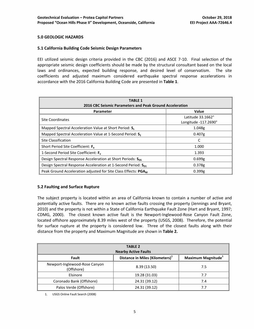
5.0 GEOLOGIC HAZARDS 5.1 California Building Code Seismic Design Parameters EEI utilized seismic design criteria provided in the CBC (2016) and ASCE 7-10. Final selection of the appropriate seismic design coefficients should be made by the structural consultant based on the local laws and ordinances, expected building response, and desired level of conservatism. The site coefficients and adjusted maximum considered earthquake spectral response accelerations in accordance with the 2016 California Building Code are presented in Table 1.
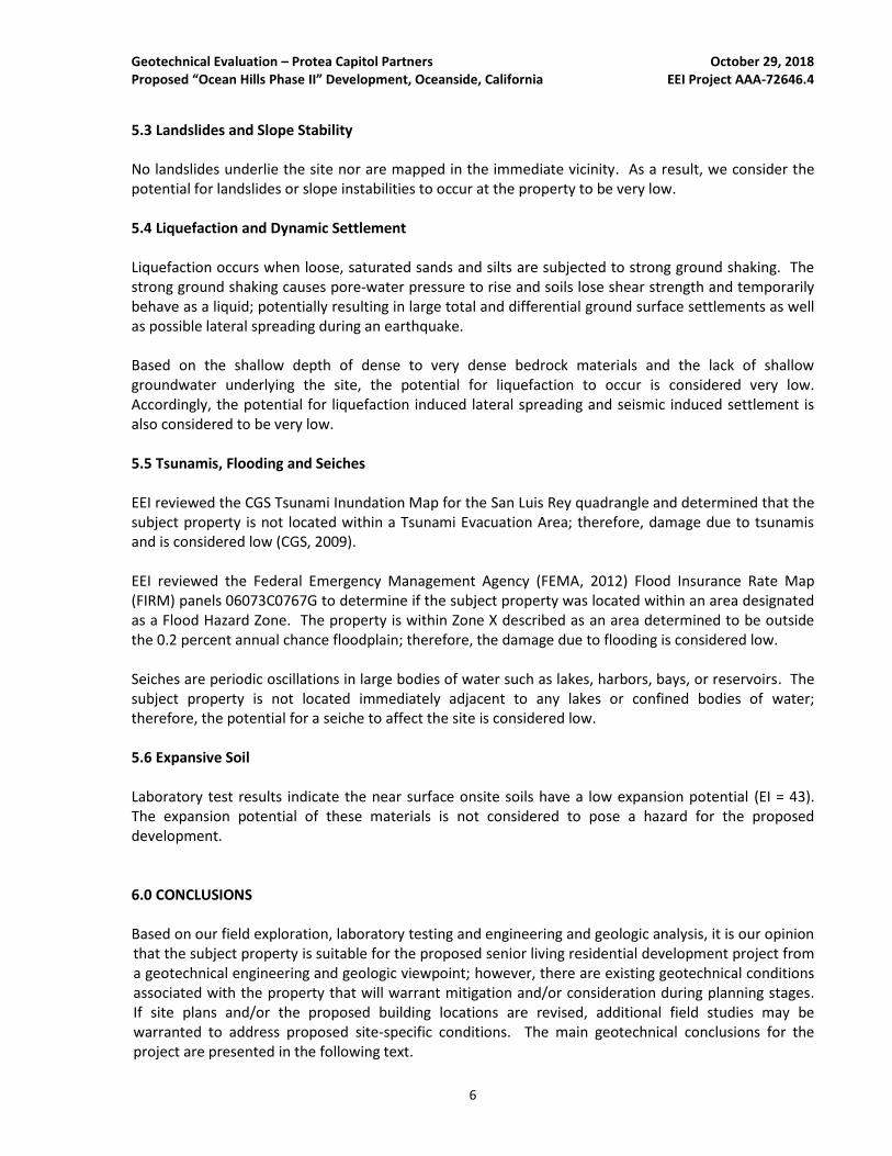
5.2 Faulting and Surface Rupture The subject property is located within an area of California known to contain a number of active and potentially active faults. There are no known active faults crossing the property (Jennings and Bryant, 2010) and the property is not within a State of California Earthquake Fault Zone (Hart and Bryant, 1997; CDMG, 2000). The closest known active fault is the Newport-Inglewood-Rose Canyon Fault Zone, located offshore approximately 8.39 miles west of the property (USGS, 2008). Therefore, the potential for surface rupture at the property is considered low. Three of the closest faults along with their distance from the property and Maximum Magnitude are shown in Table 2.
TABLE 2 Nearby Active Faults
Fault Distance in Miles (Kilometers)1 Maximum Magnitude
1
Newport-Inglewood-Rose Canyon (Offshore)
8.39 (13.50) 7.5
Elsinore 19.28 (31.03) 7.7
Coronado Bank (Offshore) 24.31 (39.12) 7.4
Palos Verde (Offshore) 24.31 (39.12) 7.7
1. USGS Online Fault Search (2008)
TABLE 1 2016 CBC Seismic Parameters and Peak Ground Acceleration
Parameter Value
Site Coordinates Latitude 33.1662°
Longitude -117.2690°
Mapped Spectral Acceleration Value at Short Period: Ss 1.048g
Mapped Spectral Acceleration Value at 1-Second Period: S1 0.407g
Site Classification C
Short Period Site Coefficient: Fa 1.000
1-Second Period Site Coefficient: Fv 1.393
Design Spectral Response Acceleration at Short Periods: SDS 0.699g
Design Spectral Response Acceleration at 1-Second Period: SD1 0.378g
Peak Ground Acceleration adjusted for Site Class Effects: PGAM 0.399g
Geotechnical Evaluation – Protea Capitol Partners October 29, 2018 Proposed “Ocean Hills Phase II” Development, Oceanside, California EEI Project AAA-72646.4
6
5.3 Landslides and Slope Stability No landslides underlie the site nor are mapped in the immediate vicinity. As a result, we consider the potential for landslides or slope instabilities to occur at the property to be very low. 5.4 Liquefaction and Dynamic Settlement Liquefaction occurs when loose, saturated sands and silts are subjected to strong ground shaking. The strong ground shaking causes pore-water pressure to rise and soils lose shear strength and temporarily behave as a liquid; potentially resulting in large total and differential ground surface settlements as well as possible lateral spreading during an earthquake. Based on the shallow depth of dense to very dense bedrock materials and the lack of shallow groundwater underlying the site, the potential for liquefaction to occur is considered very low. Accordingly, the potential for liquefaction induced lateral spreading and seismic induced settlement is also considered to be very low. 5.5 Tsunamis, Flooding and Seiches EEI reviewed the CGS Tsunami Inundation Map for the San Luis Rey quadrangle and determined that the subject property is not located within a Tsunami Evacuation Area; therefore, damage due to tsunamis and is considered low (CGS, 2009). EEI reviewed the Federal Emergency Management Agency (FEMA, 2012) Flood Insurance Rate Map (FIRM) panels 06073C0767G to determine if the subject property was located within an area designated as a Flood Hazard Zone. The property is within Zone X described as an area determined to be outside the 0.2 percent annual chance floodplain; therefore, the damage due to flooding is considered low. Seiches are periodic oscillations in large bodies of water such as lakes, harbors, bays, or reservoirs. The subject property is not located immediately adjacent to any lakes or confined bodies of water; therefore, the potential for a seiche to affect the site is considered low. 5.6 Expansive Soil Laboratory test results indicate the near surface onsite soils have a low expansion potential (EI = 43). The expansion potential of these materials is not considered to pose a hazard for the proposed development. 6.0 CONCLUSIONS Based on our field exploration, laboratory testing and engineering and geologic analysis, it is our opinion that the subject property is suitable for the proposed senior living residential development project from a geotechnical engineering and geologic viewpoint; however, there are existing geotechnical conditions associated with the property that will warrant mitigation and/or consideration during planning stages. If site plans and/or the proposed building locations are revised, additional field studies may be warranted to address proposed site-specific conditions. The main geotechnical conclusions for the project are presented in the following text.
Geotechnical Evaluation – Protea Capitol Partners October 29, 2018 Proposed “Ocean Hills Phase II” Development, Oceanside, California EEI Project AAA-72646.4
7
• A total of thirteen (13) exploratory borings were advanced within the subject property during this evaluation. The boring depths ranged from 6 to 17.5 feet bgs. The property is underlain by undocumented fill, alluvium, the Eocene Santiago Formation and Cretaceous-aged granitics.
• Groundwater was not encountered in any of our exploratory borings to the maximum explored depth of 17.5 feet bgs.
• Standard heavy-duty grading equipment is anticipated to excavate the fill soils, as well as the alluvial deposits and Santiago formation; however, granitic bedrock materials that contain very dense and hard zones requiring heavy ripping with a single shank, or a “rock breaker” should be anticipated.
• The subject property is located within an area of southern California recognized as having a number of active and potentially-active faults located nearby. Our review indicates that there are no known active faults mapped as crossing the property and the property is not located within an Earthquake Fault Zone.
• Based on EEI’s evaluation, Earth materials underlying the subject property are not considered susceptible to seismic settlement. The potential for liquefaction and seismic induced settlement are considered very low and are not considered a geotechnical concern.
• The onsite soils are predominantly silty sands and in general are anticipated to have a low expansion potential (EI ≤ 50). It should be noted, however, that localized clayey soils could potentially be expansive (EI > 50), and should be further evaluated during future studies or during earthwork when the proposed building pads are near finish grade.
• The existing fill and alluvial deposits are variable in density and are considered potentially compressible. As such, they are considered unsuitable for the support of settlement-sensitive structures or additional fill in their current condition. Therefore, these materials should be completely removed and recompacted in those areas to receive additional fill, proposed buildings and other settlement-sensitive improvements. Based on the results of our subsurface exploration, we anticipate that these removals will need to extend on the order of approximately 5 to 17 feet below existing site grades.
• A conventional shallow foundation system in conjunction with a concrete slab-on-grade floor appears to be suitable for support of the proposed residential buildings.
7.0 RECOMMENDATIONS
The recommendations presented herein should be incorporated into the planning and design phases of development. Guidelines for site preparation, earthwork, and onsite improvements are provided in the following sections.
7.1 General
Grading should conform to the guidelines presented in the 2016 California Building Code (CBC, 2016), as well as the requirements of the City of Oceanside. Additionally, general Earthwork and Grading Guidelines are provided herein as Appendix E.
Geotechnical Evaluation – Protea Capitol Partners October 29, 2018 Proposed “Ocean Hills Phase II” Development, Oceanside, California EEI Project AAA-72646.4
8
During earthwork construction, removals and reprocessing of soft or unsuitable fill and alluvial materials, as well as general grading procedures of the contractor should be observed and the fill placed should be selectively tested by representatives of the geotechnical engineer, EEI. If any unusual or unexpected conditions are exposed in the field, they should be reviewed by the geotechnical engineer and if warranted, modified and/or additional recommendations will be offered. Specific guidelines and comments pertinent to the planned development are provided herein. The recommendations presented herein have been completed using the preliminary information provided to us regarding site development. EEI should be provided with grading and foundation plans once they are available so that we can determine if the recommendations provided in this report remain applicable. 7.2 Site Preparation and Grading Debris and other deleterious material, such as organic soils, tree rootballs and/or environmentally impacted earth materials (if any) should be removed from the subject property prior to the start of grading. All undocumented fill/backfill should be removed and recompacted. Areas to receive fill should be properly scarified and/or benched in accordance with current industry standards of practice and guidelines specified in the CBC (2016) and the requirements of the local jurisdiction. Abandoned trenches should be properly backfilled and tested. If unanticipated subsurface improvements (utility lines, septic systems, wells, utilities, etc.) are encountered during earthwork construction, the Geotechnical Engineer should be informed and appropriate remedial recommendations would then be provided. 7.3 Remedial Earthwork Remedial grading for the proposed residential building pads and for pavement and hardscape areas is provided in the following sections. Unless noted otherwise, fill should be moisture conditioned to at least the optimum moisture content and compacted to at least 90 percent of the maximum dry density (based on ASTM D1557). Building Pads and other Settlement Sensitive Structures: The existing fill materials are undocumented, variable in density, possess variable expansion potential, and are considered potentially compressible. Underlying alluvial materials vary in density and moisture, and are also considered potentially compressible. As such, the fill and alluvial soils are considered unsuitable for the support of settlement-sensitive structures or additional fill in their current condition. Based on this information, we recommend the removal (over-excavation) and re-compaction of the fill and alluvial materials within the proposed grading limits of the building pad areas and other settlement sensitive structures. Therefore, where not already removed by the proposed site grading, the existing undocumented fill and underlying alluvium should be completely removed and recompacted in those areas to receive additional fill, proposed buildings and other settlement-sensitive improvements in order to help reduce the expansion potential of locally clayey materials, and provide relatively uniform soil bearing conditions in the proposed development areas. Based on the results of our subsurface exploration and geotechnical evaluation, we recommend that the removals extend down to the relatively competent Santiago Formation or Granitic bedrock materials. Removals of the potentially compressible materials identified herein are anticipated to range from approximately 5 to 15 feet. The
Geotechnical Evaluation – Protea Capitol Partners October 29, 2018 Proposed “Ocean Hills Phase II” Development, Oceanside, California EEI Project AAA-72646.4
9
removals should extend to a minimum of 5 feet bgs or 18-inches below the bottom of foundations, whichever is deeper in the proposed building area. The remedial earthwork should extend a minimum of 5 feet beyond the proposed area to support fill and/or settlement sensitive improvements. The resulting excavation(s) for the removals should be observed by a representative of EEI to check that unsuitable materials have been sufficiently removed. It should be understood that based on the observations of our field representative, localized deeper removals may be recommended. The base of the removal area should be level to avoid differential fill thicknesses under proposed improvements. Note that vertical sides exceeding five feet in depth may be prone to sloughing and may require laying back to an inclination of 1:1 (horizontal to vertical). Some locations that are close to property lines and existing improvements may require temporary shoring or slot cutting methods. The base of the removals should be scarified to a minimum depth of 6-inches, moisture conditioned as needed to achieve at least optimum moisture content and re-compacted to at least 90 percent of the maximum dry density (based on ASTM D1557). The over-excavated areas should then be backfilled with onsite and/or imported soils that are placed and compacted as recommended herein until design finish grades are reached. Other Settlement Sensitive Structures: Similar remedial grading should be performed below other settlement sensitive improvements such as retaining walls and street improvements, pool areas and hardscape areas. If over-excavations for improvements are not performed in these areas, these improvements may be subject to settlement. 7.4 Fill Material and Placement Fill materials should be compacted to at least 90 percent of the maximum dry density (based on ASTM D1557). Unless noted otherwise, fill should be moisture conditioned to at least 2 percent above the optimum moisture content and compacted to at least 90 percent of the maximum dry density (based on ASTM D1557). Fill material should be free of organic matter (less than 3 percent organics by weight) and other deleterious material. Fill material should not contain rocks greater than 6-inches in maximum dimension, organic debris and other deleterious materials. Rock fragments exceeding 6-inches in one dimension should be segregated and exported from the subject property or utilized for landscaping. Conventional Shallow Foundations with Slab on Grade: Fill within 4 feet of pad grade should consist of low expansion potential material (EI < 50). The low-expansion potential material should extend at least 5 feet beyond the building perimeter. Hardscape: Fill within 2 feet of hardscape subgrade should consist of low-expansive material (EI < 50). The low-expansion potential material should extend at least 2 feet beyond the hardscape. If import soils are needed, the earthwork contractor should ensure that all proposed fill materials are approved by the Geotechnical Engineer prior to use. Representative soil samples should be made available for testing at least ten (10) working days prior to hauling to the property to allow for laboratory tests. Those areas to receive fill or surface improvements should be scarified at least 6-inches; moisture conditioned to at least 2 percent over optimum moisture content and re-compacted to at least 90 percent of the maximum dry density (based on ASTM D1557). The subgrade should be thoroughly and uniformly moistened prior to placing concrete.
Geotechnical Evaluation – Protea Capitol Partners October 29, 2018 Proposed “Ocean Hills Phase II” Development, Oceanside, California EEI Project AAA-72646.4
10
7.5 Expansive Soil The onsite soils are anticipated to possess a low expansion potential (EI=21-50). The recommendations presented in this report reflect a low expansion potential. 7.6 Yielding Subgrade Conditions The soils encountered at the subject property can exhibit “pumping” or yielding if they become saturated. This can often occur in response to periods of significant precipitation, such as during the winter rainy season. If this occurs and in order to help stabilize the yielding subgrade soils within the bottom of the removal areas, the contractor can consider the placement of stabilization fabric or geo-grid over the yielding areas, depending on the relative severity. Mirafi 600X (or approved equivalent) stabilization fabric may be used for areas with low to moderate yielding conditions. Geo-grid such as Tensar TX-5 may be used for areas with moderate to severe yielding conditions. Uniform sized, ¾- to 2-inch crushed rock should be placed over the stabilization fabric or geo-grid. A 6- to 12-inch thick section of crushed rock will typically be necessary to stabilize yielding ground. If significant voids are present in the crushed gravel, a filter fabric should be placed over the crushed gravel to prevent migration of fines into the gravel and subsequent settlement of the overlying fill. Fill soils, which should be placed and compacted in accordance with the recommendations presented herein, should then be placed over the fabric or geo-grid until design finish grades are reached. The crushed gravel and stabilization fabric or geo-grid should extend at least 5 feet laterally beyond the limits of the yielding areas. These operations should be performed under the observation and testing of a representative of EEI in order to evaluate the effectiveness of these measures and to provide additional recommendations for mitigation, as necessary. 7.7 Shrinkage and Bulking Several factors will impact earthwork balancing on the subject property, including shrinkage, bulking, subsidence, trench spoils from utilities and footing excavations, and final pavement section thickness as well as the accuracy of topography. Shrinkage, bulking and subsidence are primarily dependent upon the degree of compactive effort achieved during construction. Shrinkage, bulking and subsidence should be considered by the project civil engineer relative to final site balancing. It is recommended that the site development be planned to include an area that could be raised or lowered to accommodate final site balancing. 7.8 Temporary Site Excavations Based on the results of our subsurface exploration, we anticipate that excavations can generally be accomplished by conventional heavy duty earth moving equipment in good working condition. However, excavations may encounter localized harder, cemented zones that may require air hammer attachments to excavators, or specialized excavation equipment. Excavations in the onsite materials could generate oversize materials. Oversize materials should be placed in accordance with Section 7.5 and the Earthwork and Grading Guidelines.
Geotechnical Evaluation – Protea Capitol Partners October 29, 2018 Proposed “Ocean Hills Phase II” Development, Oceanside, California EEI Project AAA-72646.4
11
Temporary excavations within the onsite materials (considered to be a Type C soil per OSHA guidelines) should be stable at 1.5H:1V inclinations for short durations during construction, and where cuts do not exceed 15 feet in height. Some sloughing of surface soils should be anticipated. Temporary excavations 4 feet deep or less can be made vertically. The faces of temporary slopes should be inspected daily by the contractor’s Competent Person before personnel are allowed to enter the excavation. Any zones of potential instability, sloughing or raveling should be brought to the attention of the Engineer and corrective action implemented before personnel begin working in the excavation. Excavated soils should not be stockpiled behind temporary excavations within a distance equal to the depth of the excavation. EEI should be notified if other surcharge loads are anticipated so that lateral load criteria can be developed for the specific situation. If temporary slopes are to be maintained during the rainy season, berms are recommended along the tops of slopes to prevent runoff water from entering the excavation and eroding the slope faces. 8.0 FOUNDATION RECOMMENDATIONS 8.1 General In the event that plans concerning the proposed building structures are revised in the project design and/or location or loading conditions of the planned structures are made, conclusions and recommendations contained in this report should not be considered valid unless they are reviewed, revised and/or approved in writing by EEI. 8.2 Preliminary Foundation Design The following design parameters assume that the minimum recommended remedial grading will be performed, and that foundations for the proposed residential buildings will consist of conventional shallow foundations with a slab on grade. The foundation recommendations provided herein are based on the soil materials within 30-inches of foundation level possessing a low expansion potential (EI<50). Recommendations by the project's design-structural engineer or architect may exceed the following minimum recommendations. In preparation for foundation construction, the earthwork contractor should ensure that the site has been prepared as recommended, and that field density tests have been performed to adequately document the relative compaction of structural fill. Foundation design recommendations for the proposed structure is provided in the following sections of this report.
8.2.1 Conventional Shallow Foundations For proposed one-story wood frame residential buildings, conventional continuous and/or isolated shallow spread footings should bear entirely on compacted fill with remedial grading as described in previous sections of this report. Foundations should be constructed with an embedment of at least 12-inches below finish grade and a minimum width of 12-inches. Isolated footings should have a minimum width of 24-inches. An allowable bearing capacity of 2,000 pounds per square foot (psf) can be used for footings extending at least 12-inches below
Geotechnical Evaluation – Protea Capitol Partners October 29, 2018 Proposed “Ocean Hills Phase II” Development, Oceanside, California EEI Project AAA-72646.4
12
lowest adjacent finished grade. The allowable bearing may be increased by 750 psf for each additional 12-inches of embedment up to a maximum bearing of 3,000 psf. The bearing value can be increased by ⅓ when considering the total of all loads, including wind or seismic forces. For proposed two-story wood frame residential buildings, conventional continuous and/or isolated shallow spread footings should bear entirely on compacted fill with remedial grading as described in previous sections of this report. Foundations should be constructed with an embedment of at least 18-inches below finish grade and a minimum width of 15-inches. Isolated footings should have a minimum width of 24-inches. An allowable bearing capacity of 2,000 pounds per square foot (psf) can be used for footings extending at least 12-inches below lowest adjacent finished grade. The allowable bearing may be increased by 750 psf for each additional 12-inches of embedment up to a maximum bearing of 3,000 psf. The bearing value can be increased by ⅓ when considering the total of all loads, including wind or seismic forces. For proposed three-story wood frame residential buildings, conventional continuous and/or isolated shallow spread footings should bear entirely on compacted fill with remedial grading as described in previous sections of this report. Foundations should be constructed with an embedment of at least 24-inches below finish grade and a minimum width of 18-inches. Isolated footings should have a minimum width of 24-inches. An allowable bearing capacity of 2,000 pounds per square foot (psf) can be used for footings extending at least 24-inches below lowest adjacent finished grade. The allowable bearing may be increased by 750 psf for each additional 12-inches of embedment up to a maximum bearing of 3,000 psf. The bearing value can be increased by ⅓ when considering the total of all loads, including wind or seismic forces. Based on the prevailing geotechnical conditions encountered during our geotechnical evaluation as described herein, we recommend that foundations be reinforced with at least two No. 4 bars, one placed at the top of the footing and one placed at the bottom. The recommendations for footings sizes and reinforcement are considered minimums and are not intended to supersede the design of the project structural engineer.
8.3 Lateral loads Lateral loads will be resisted by friction between the bottoms of foundations and passive pressure on the faces of footings and other structural elements below grade. An allowable passive pressure of 300 psf per foot of depth can be used for the portion of the foundation below grade. An allowable coefficient of friction of 0.30 can be used. The passive pressure can be increased by ⅓ when considering the total of all loads, including wind or seismic forces. The upper one-foot of soil should not be relied on for passive support unless the ground is covered with pavements or slabs. 8.4 Settlement Settlement estimates for conventional foundations are as follows:
• Static Total Settlement: Less than 1-inch • Static Differential Settlement: Less than ½-inch over a distance of 40 feet
Geotechnical Evaluation – Protea Capitol Partners October 29, 2018 Proposed “Ocean Hills Phase II” Development, Oceanside, California EEI Project AAA-72646.4
13
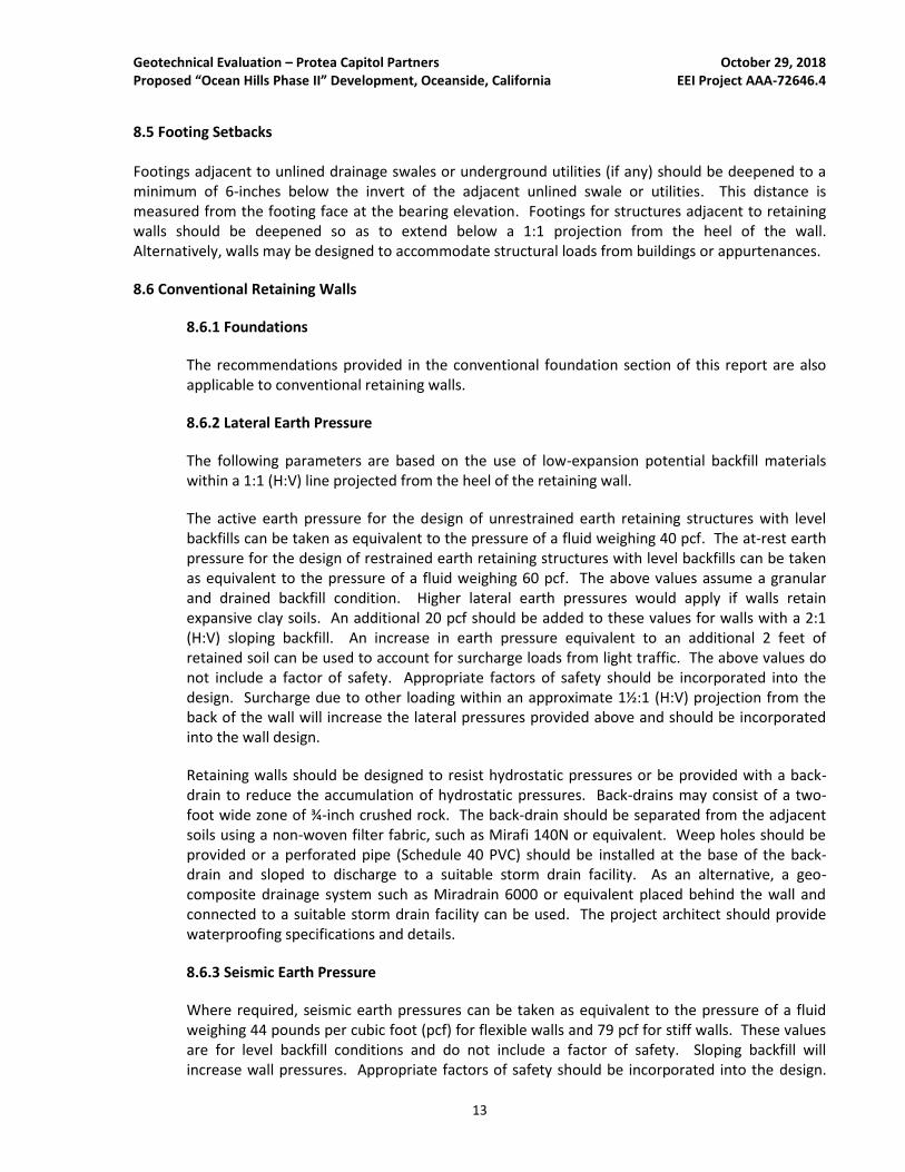
8.5 Footing Setbacks Footings adjacent to unlined drainage swales or underground utilities (if any) should be deepened to a minimum of 6-inches below the invert of the adjacent unlined swale or utilities. This distance is measured from the footing face at the bearing elevation. Footings for structures adjacent to retaining walls should be deepened so as to extend below a 1:1 projection from the heel of the wall. Alternatively, walls may be designed to accommodate structural loads from buildings or appurtenances.
8.6 Conventional Retaining Walls
8.6.1 Foundations
The recommendations provided in the conventional foundation section of this report are also applicable to conventional retaining walls.
8.6.2 Lateral Earth Pressure
The following parameters are based on the use of low-expansion potential backfill materials within a 1:1 (H:V) line projected from the heel of the retaining wall.
The active earth pressure for the design of unrestrained earth retaining structures with level backfills can be taken as equivalent to the pressure of a fluid weighing 40 pcf. The at-rest earth pressure for the design of restrained earth retaining structures with level backfills can be taken as equivalent to the pressure of a fluid weighing 60 pcf. The above values assume a granular and drained backfill condition. Higher lateral earth pressures would apply if walls retain expansive clay soils. An additional 20 pcf should be added to these values for walls with a 2:1 (H:V) sloping backfill. An increase in earth pressure equivalent to an additional 2 feet of retained soil can be used to account for surcharge loads from light traffic. The above values do not include a factor of safety. Appropriate factors of safety should be incorporated into the design. Surcharge due to other loading within an approximate 1½:1 (H:V) projection from the back of the wall will increase the lateral pressures provided above and should be incorporated into the wall design.
Retaining walls should be designed to resist hydrostatic pressures or be provided with a back-drain to reduce the accumulation of hydrostatic pressures. Back-drains may consist of a two-foot wide zone of ¾-inch crushed rock. The back-drain should be separated from the adjacent soils using a non-woven filter fabric, such as Mirafi 140N or equivalent. Weep holes should be provided or a perforated pipe (Schedule 40 PVC) should be installed at the base of the back-drain and sloped to discharge to a suitable storm drain facility. As an alternative, a geo-composite drainage system such as Miradrain 6000 or equivalent placed behind the wall and connected to a suitable storm drain facility can be used. The project architect should provide waterproofing specifications and details.
8.6.3 Seismic Earth Pressure
Where required, seismic earth pressures can be taken as equivalent to the pressure of a fluid weighing 44 pounds per cubic foot (pcf) for flexible walls and 79 pcf for stiff walls. These values are for level backfill conditions and do not include a factor of safety. Sloping backfill will increase wall pressures. Appropriate factors of safety should be incorporated into the design.
Geotechnical Evaluation – Protea Capitol Partners October 29, 2018 Proposed “Ocean Hills Phase II” Development, Oceanside, California EEI Project AAA-72646.4
14
The seismic pressure is in addition to the un-factored static active pressures. The allowable passive pressure and bearing capacity can be increased by ⅓ in determining the stability of the wall.
8.7 Interior Slabs-on-Grade
The project structural engineer should design the interior concrete slab-on-grade floor. We recommend that building slabs be at least 4-inches in thickness and that consideration be given to the slab being reinforced with No. 3 bars spaced 18-inches on center, each way, and placed at slab mid-height, or the slab reinforcement in accordance with the structural engineers design. Subgrade materials should not be allowed to desiccate between grading and the construction of the concrete slabs. The floor slab subgrade should be thoroughly and uniformly moistened prior to placing concrete.
A moisture vapor retarder/barrier should be placed beneath slabs where moisture sensitive floor coverings will be installed. Typically, plastic is used as a vapor retardant. If plastic is used, a minimum 10-mil is recommended. The plastic should comply with ASTM E1745. Plastic installation should comply with ASTM E1643.
Current construction practice typically includes placement of a 2-inch thick sand cushion between the bottom of the concrete slab and the moisture vapor retarder/barrier. This cushion can provide some protection to the vapor retarder/barrier during construction and may assist in reducing the potential for edge curling in the slab during curing. However, the sand layer also provides a source of moisture vapor
to the underside of the slab that can increase the time required to reduce moisture vapor emissions to limits acceptable for the type of floor covering placed on top of the slab. The slab can be placed directly on the vapor retarder/barrier. The floor covering manufacturer should be contacted to determine the volume of moisture vapor allowable and any treatment needed to reduce moisture vapor emissions to acceptable limits for the particular type of floor covering installed. The project team should determine the appropriate treatment for the specific application.
8.8 Exterior Slabs-on-Grade (Hardscape)
The top 24-inches of soil below exterior concrete slabs-on-grade should have an expansion index of 50 or less. Exterior slabs should have a minimum thickness of 4-inches and consideration given to be reinforced with at least No. 3 bars at 24-inches on center each way. Slabs should be provided with weakened plane joints. Joints should be placed in accordance with the American Concrete Institute (ACI) guidelines. Proper control joints should be provided to reduce the potential for damage resulting from shrinkage. Subgrade materials should not be allowed to desiccate between grading and the construction of the concrete slabs. The floor slab subgrade should be thoroughly and uniformly moistened prior to placing concrete.
All dedicated exterior flatwork should conform to standards provided by the governing agency including section composition, supporting material thickness and any requirements for reinforcing steel. Concrete mix proportions and construction techniques, including the addition of water and improper curing, can adversely affect the finished quality of the concrete and result in cracking and spalling of the slab. We recommend that all placement and curing be performed in accordance with procedures outlined by the American Concrete Institute and/or Portland Cement Association. Special consideration should be given to concrete placed and cured during hot or cold weather conditions.
Geotechnical Evaluation – Protea Capitol Partners October 29, 2018 Proposed “Ocean Hills Phase II” Development, Oceanside, California EEI Project AAA-72646.4
15
8.9 Corrosivity One sample of the onsite soils was tested to provide a preliminary indication of the corrosion potential of the onsite soils. The test results are presented in Appendix B. A brief discussion of the corrosion test results is provided in the following section.
• The sample tested had a soluble sulfate concentration of 0.025 percent, which indicates the sample has a negligible sulfate corrosion potential relative to concrete.
• It should be noted that soluble sulfate in the irrigation water supply, and/or the use of fertilizer may cause the sulfate content in the surficial soils to increase with time. This may result in a higher sulfate exposure than that indicated by the test results reported herein. Studies have shown that the use of improved cements in the concrete, and a low water-cement ratio will improve the resistance of the concrete to sulfate exposure.
• The sample tested had a chloride concentration of 0.026 percent, which indicates the sample has a negligible chloride corrosion potential relative to metal.
• The sample tested had a minimum resistivity of 520 ohm-cm, which indicates the sample is extremely corrosive to ferrous metals.
• The sample tested had a pH of 7.0, which indicates the sample is neutral.
Additional testing should be performed after grading to evaluate the as-graded corrosion potential of the onsite soils. We are not corrosion engineers. A corrosion consultant should be retained to provide corrosion control recommendations if deemed necessary. 9.0 PRELIMINARY PAVEMENT DESIGN RECOMMENDATIONS Deleterious material, excessively wet or dry pockets, concentrated zones of oversized rock fragments, and any other unsuitable yielding materials encountered during grading should be removed. Once compacted fill and/or native soils are brought to the proposed pavement subgrade elevations, the subgrade should be proof-rolled in order to check for a uniform firm and unyielding surface. Representatives of the project Geotechnical Engineer should observe all grading and fill placement. The upper 12-inches of pavement subgrade soils should be scarified; moisture conditioned to at least optimum moisture content and compacted to at least 95 percent of the laboratory standard (ASTM D1557). If loose or yielding materials are encountered during subgrade preparation, evaluation should be performed by EEI. Aggregate base materials should be properly prepared (i.e., processed and moisture conditioned) and compacted to at least 95 percent of the maximum dry density as determined by ASTM D1557. Aggregate base materials should conform to Caltrans specifications for Class 2 aggregate base. All pavement section changes should be properly transitioned. Although not anticipated, if adverse conditions are encountered during the preparation of subgrade materials, special construction methods may need to be employed. A representative of the project Geotechnical Engineer should be present for the preparation of subgrade and aggregate base.
Geotechnical Evaluation – Protea Capitol Partners October 29, 2018 Proposed “Ocean Hills Phase II” Development, Oceanside, California EEI Project AAA-72646.4
16
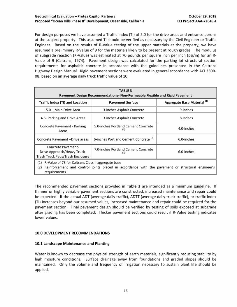
For design purposes we have assumed a Traffic Index (TI) of 5.0 for the drive areas and entrance aprons at the subject property. This assumed TI should be verified as necessary by the Civil Engineer or Traffic Engineer. Based on the results of R-Value testing of the upper materials at the property, we have assumed a preliminary R-Value of 9 for the materials likely to be present at rough grades. The modulus of subgrade reaction (K-Value) was estimated at 70 pounds per square inch per inch (psi/in) for an R-Value of 9 (Caltrans, 1974). Pavement design was calculated for the parking lot structural section requirements for asphaltic concrete in accordance with the guidelines presented in the Caltrans Highway Design Manual. Rigid pavement sections were evaluated in general accordance with ACI 330R-08, based on an average daily truck traffic value of 10.
The recommended pavement sections provided in Table 3 are intended as a minimum guideline. If thinner or highly variable pavement sections are constructed, increased maintenance and repair could be expected. If the actual ADT (average daily traffic), ADTT (average daily truck traffic), or traffic index (TI) increases beyond our assumed values, increased maintenance and repair could be required for the pavement section. Final pavement design should be verified by testing of soils exposed at subgrade after grading has been completed. Thicker pavement sections could result if R-Value testing indicates lower values. 10.0 DEVELOPMENT RECOMMENDATIONS 10.1 Landscape Maintenance and Planting Water is known to decrease the physical strength of earth materials, significantly reducing stability by high moisture conditions. Surface drainage away from foundations and graded slopes should be maintained. Only the volume and frequency of irrigation necessary to sustain plant life should be applied.
TABLE 3 Pavement Design Recommendations- Non-Permeable Flexible and Rigid Pavement
Traffic Index (TI) and Location Pavement Surface Aggregate Base Material (1)
5.0 – Main Drive Area 3-inches Asphalt Concrete 9-inches
4.5- Parking and Drive Areas 3-inches Asphalt Concrete 8-inches
Concrete Pavement - Parking Areas
5.0-inches Portland Cement Concrete (2)
4.0-inches
Concrete Pavement –Drive areas 6-inches Portland Cement Concrete (2)
6.0-inches
Concrete Pavement- Drive Approach/Heavy Truck-
Trash Truck Pads/Trash Enclosure
7.0-inches Portland Cement Concrete (2)
6.0-inches
(1) R-Value of 78 for Caltrans Class II aggregate base (2) Reinforcement and control joints placed in accordance with the pavement or structural engineer’s
requirements
Geotechnical Evaluation – Protea Capitol Partners October 29, 2018 Proposed “Ocean Hills Phase II” Development, Oceanside, California EEI Project AAA-72646.4
17
Consideration should be given to selecting lightweight, deep rooted types of landscape vegetation which require low irrigation that are capable of surviving the local climate. From a soils engineering viewpoint, “leaching” of the onsite soils is not recommended for establishing landscaping. If landscape soils are processed for the addition of amendments, the processed soils should be re-compacted to at least 90 percent relative compaction (based on ASTM D1557). 10.2 Site Drainage Positive site drainage should be maintained at all times. Drainage should not flow uncontrolled over slopes. Runoff should be channeled away from slopes and structures and not allowed to pond and/or seep uncontrolled into the ground. Pad drainage should be directed toward an acceptable outlet. Consideration should be given to eliminating open bottom planters directly adjacent to proposed structures for a minimum distance of 10 feet. As an alternative, closed-bottom type planters could be utilized, with a properly designed drain outlet placed in the bottom of the planter. Final surface grades around structures should be designed to collect and direct surface water away from structures and toward appropriate drainage facilities. The ground around the structure should be graded so that surface water flows rapidly away from the structure without ponding. In general, we recommend that the ground adjacent to the structure slope away at a gradient of at least 2 percent. Densely vegetated areas where runoff can be impaired should have a minimum gradient of at least 5 percent within the first 5 feet from the structure. Roof gutters with downspouts that discharge directly into a closed drainage system are recommended on structures. Drainage patterns established at the time of fine grading should be maintained throughout the life of the proposed structures. 10.3 Site Runoff Considerations - Stormwater Disposal Systems It is our understanding that the Client is considering that runoff generated from the facility to be disposed of in engineered subsurface features onsite. We performed percolation testing in order to provide an indication of the infiltration characteristics of the onsite materials. Our testing and findings are summarized in the following sections. 10.3.1 Percolation Testing
Two percolation tests were performed onsite: B-1/P-1 and B-4/P-2 were performed during the subsurface exploration on October 9, 2018, at the location of the proposed detention basin in the western part of the property. Following the drilling of exploratory borings B-1/P-1 and B-4/P-2, a 3-inch diameter perforated polyvinyl chloride (PVC) pipe was placed in the hole and gravel was placed around the pipe. The test holes were presoaked in general accordance with the City of Oceanside BMP guidelines (City of Oceanside, 2016). Percolation testing was performed until consistent results were obtained. The results were used to calculate the pre-adjusted percolation rate for the test hole. Upon conclusion of testing, the perforated pipe was removed from the test hole and the test hole was backfilled. We note that a soil profile’s percolation rate is not the same as its infiltration rate. Therefore, the measured/calculated field percolation rate was converted to an estimated infiltration rate utilizing a reduction factor determined using the Porchet method. Additionally, as indicated in the County of San Diego BMP guidelines (County of San Diego, 2016) and City of Oceanside BMP
Geotechnical Evaluation – Protea Capitol Partners October 29, 2018 Proposed “Ocean Hills Phase II” Development, Oceanside, California EEI Project AAA-72646.4
18
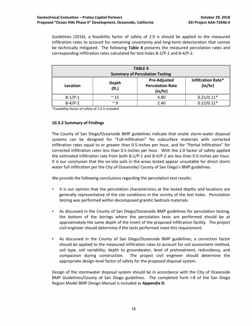
Guidelines (2016), a feasibility factor of safety of 2.0 is should be applied to the measured infiltration rates to account for remaining uncertainty and long-term deterioration that cannot be technically mitigated. The following Table 4 presents the measured percolation rates and corresponding infiltration rates calculated for test holes B-1/P-1 and B-4/P-2.
TABLE 4 Summary of Percolation Testing
Location Depth
(ft.)
Pre-Adjusted Percolation Rate
(in/hr)
Infiltration Rate* (in/hr)
B-1/P-1 ~ 15 4.80 0.21/0.11*
B-4/P-2 ~ 9 2.40 0.22/0.11* *Feasibility factor of safety of 2.0 is included
10.3.2 Summary of Findings The County of San Diego/Oceanside BMP guidelines indicate that onsite storm-water disposal systems can be designed for “Full-Infiltration” for subsurface materials with corrected infiltration rates equal to or greater than 0.5-inches per hour, and for “Partial Infiltration” for corrected infiltration rates less than 0.5-inches per hour. With the 2.0 factor of safety applied the estimated infiltration rate from both B-1/P-1 and B-4/P-2 are less than 0.5-inches per hour. It is our conclusion that the on-site soils in the areas tested appear unsuitable for direct storm water full infiltration per the City of Oceanside/ County of San Diego’s BMP guidelines. We provide the following conclusions regarding the percolation test results: • It is our opinion that the percolation characteristics at the tested depths and locations are
generally representative of the site conditions in the vicinity of the test holes. Percolation testing was performed within decomposed granitic bedrock materials.
• As discussed in the County of San Diego/Oceanside BMP guidelines for percolation testing, the bottom of the borings where the percolation tests are performed should be at approximately the same depth of the invert of the proposed infiltration facility. The project civil engineer should determine if the tests performed meet this requirement.
• As discussed in the County of San Diego/Oceanside BMP guidelines, a correction factor should be applied to the measured infiltration rates to account for soil assessment method, soil type, soil variability, depth to groundwater, level of pretreatment, redundancy, and compaction during construction. The project civil engineer should determine the appropriate design-level factor of safety for the proposed disposal system.
Design of the stormwater disposal system should be in accordance with the City of Oceanside BMP Guidelines/County of San Diego guidelines. The completed form I-8 of the San Diego Region Model BMP Design Manual is included as Appendix D.
Geotechnical Evaluation – Protea Capitol Partners October 29, 2018 Proposed “Ocean Hills Phase II” Development, Oceanside, California EEI Project AAA-72646.4
19
10.3.3 Structure Setback from Retention Devices We recommend that storm-water disposal systems be situated at least three times their depth, or a minimum of 15 feet (whichever is greater), from the outside bottom edge of structural foundations. Structural foundations include (but are not limited to) buildings, loading docks, retaining walls, and screen walls. The invert of storm-water infiltration should be outside a 1:1 (H:V) plane projected from the bottom of adjacent foundations. Stormwater disposal systems should be checked and maintained on regular intervals. Stormwater devices including bio-swales that are located closer than 10 feet from any foundations/footings should be lined with an impermeable membrane to reduce the potential for saturation of foundation soils. Foundations may also need to be deepened. Storm water infiltration should not be located near utility lines where the introduction of storm water could cause damage to utilities or settlement of trench backfill.
10.4 Additional Site Improvements
Recommendations for additional grading can be provided upon request. If in the future, additional property improvements are planned for the subject property, recommendations concerning the design and construction of improvements would be provided upon request.
10.5 Utility Trench Backfill
Fill around the pipe should be placed in accordance with details shown on the drawings and should be placed in layers not to exceed 8-inches loose (unless otherwise approved by the geotechnical engineer) and compacted to at least 90 percent of the maximum dry density as determined in accordance with ASTM D1557 (Modified Proctor). The geotechnical engineer should approve all backfill material. Select material should be used when called for on the drawings, or when recommended by the geotechnical engineer. Care should be taken during backfill and compaction operations to maintain alignment and prevent damage to the joints. The backfill should be kept free from oversized material, chunks of highly plastic clay, or other unsuitable or deleterious material. Backfill soils should be non-expansive, non-corrosive, and compatible with native earth materials. Backfill materials and testing should be in accordance with the CBC (2016), and the requirements of the local governing jurisdiction.
Pipe backfill areas should be graded and maintained in such a condition that erosion or saturation will not damage the pipe bedding or backfill. Flooding trench backfill is not recommended. Heavy equipment should not be operated over any pipe until it has been properly backfilled with a minimum of 2 to 3 feet of cover. The utility trench should be systematically backfilled to allow maximum time for natural settlement. Backfill should not occur over porous, wet, or spongy subgrade surfaces. Should these conditions exist, the areas should be removed, replaced and recompacted.
11.0 PLAN REVIEW
Once detailed grading and foundation plans are available, they should be submitted to EEI for review and comment, to reduce the potential for discrepancies between plans and recommendations presented herein. If conditions found differ substantially from those stated; appropriate recommendations will be provided. Additional field studies may be warranted.
Geotechnical Evaluation – Protea Capitol Partners October 29, 2018 Proposed “Ocean Hills Phase II” Development, Oceanside, California EEI Project AAA-72646.4
20
12.0 LIMITATIONS This Geotechnical Evaluation has been conducted in accordance with generally accepted geotechnical engineering principles and practices. Findings provided herein have been derived in accordance with current standards of practice, and no warranty is expressed or implied. Standards of practice are subject to change with time. This report has been prepared for the sole use of Protea Senior Living Oceanside, LLC (Client), within a reasonable time from its authorization. Subject property conditions, land use (both onsite and offsite), or other factors may change as a result of manmade influences, and additional work may be required with the passage of time. This Geotechnical Evaluation should not be relied upon by other parties without the express written consent of EEI and the Client; therefore, any use or reliance upon this Geotechnical Evaluation by a party other than the Client should be solely at the risk of such third party and without legal recourse against EEI, its employees, officers, or directors, regardless of whether the action in which recovery of damages is brought or based upon contract, tort, statue, or otherwise. The Client has the responsibility to see that all parties to the project, including the designer, contractor, subcontractor, and building official, etc. are aware of this report in its complete form. This report contains information that may be used in the preparation of contract specifications; however, the report is not designed as a specification document, and may not contain sufficient information for use without additional assessment. EEI assumes no responsibility or liability for work or testing performed by others. In addition, this report may be subject to review by the controlling authorities.
Geotechnical Evaluation – Protea Capitol Partners October 29, 2018 Proposed “Ocean Hills Phase II” Development, Oceanside, California EEI Project AAA-72646.4
21
13.0 REFERENCES American Society of Civil Engineers (ASCE), 2010, Minimum Design Loads for Buildings and Other Structures, ASCE Document ASCE/SEI 7-10. American Society for Testing and Materials (ASTM), 2015, Annual Book of ASTM Standards, Volume 04.08, Construction: Soil and Rock (I), Standards D 420 - D 5876. California Building Code (CBC), 2016, California Code of Regulations, Title 24, Part 2, Volume 2 of 2, California Building Standards Commission, Based on 2015 International Building Code; 2016 California Historical Building Code, Title 24, Part 8; and 2013 California Existing Building Code, Title 24, Part 10, effective January 1, 2017. California Department of Transportation (Caltrans), 1974, Highway Design Manual, dated October 1, 1974. California Division of Mines and Geology (CDMG), 2000, California Department of Conservation, Digital Images of Official Maps of Alquist-Priolo Earthquake Fault Zones of California, Southern Region, DMG CD 2000-003.
California Geological Survey (CGS), 2002, California Geomorphic Provinces Note 36, Electronic Copy, Revised December 2002. California Geological Survey (CGS), 2009, Tsunami Inundation Map for Emergency Planning: San Luis Rey Quadrangle, California Geological Survey and University of Southern California, dated June 1, 2009, scale 1:24,000. City of Oceanside, 2016, Oceanside BMP Design Manual, Oceanside Department of Public Works, dated February 2016. County of San Diego, 2016, Model Best Management Practices (BMP) Design Manual, San Diego Region, For Permanent Site Design, Storm Water Treatment and Hydromodification Management, dated February 2016. Federal Emergency Management Agency (FEMA), 2012, Flood Insurance Rate Map 06073C0767G, San Diego County, California, dated May 16, 2012. Google Earth®, 2018, Version 7.1.5.1557. Hart, E.W., and Bryant, W.A. (Hart and Bryant), 1997, Fault-Rupture Hazard Zones in California: California Department of Conservation, Division of Mines and Geology, Special Publication 42. Jennings, C.W., and Bryant, W.A., (Jennings and Bryant) 2010, Fault Activity Map of California and Adjacent Areas: California Geologic Survey, Map Sheet No. 6, scale 1:750,000. Kennedy, M.P., and S.S. Tan, 2007, Geologic Map of the Oceanside 30’ x 60’ Quadrangle, California, California Geological Survey, Regional Geologic Map Series No. 2, scale 1:100,000.

Geotechnical Evaluation – Protea Capitol Partners October 29, 2018 Proposed “Ocean Hills Phase II” Development, Oceanside, California EEI Project AAA-72646.4
22
United States Geological Survey (USGS), 2018, 7.5 Minute Topographic Map, San Luis Rey, California Quadrangle, scale 1:24,000. United States Geological Survey (USGS), 2008, 2008 National Seismic Hazard Maps – Online Fault Database Search, web address < http://earthquake.usgs.gov/hazards/products/conterminous/>, accessed June 2016.

Geotechnical Evaluation – Protea Capitol Partners October 29, 2018 Proposed “Ocean Hills Phase II” Development, Oceanside, California EEI Project AAA-72646.4
FIGURES
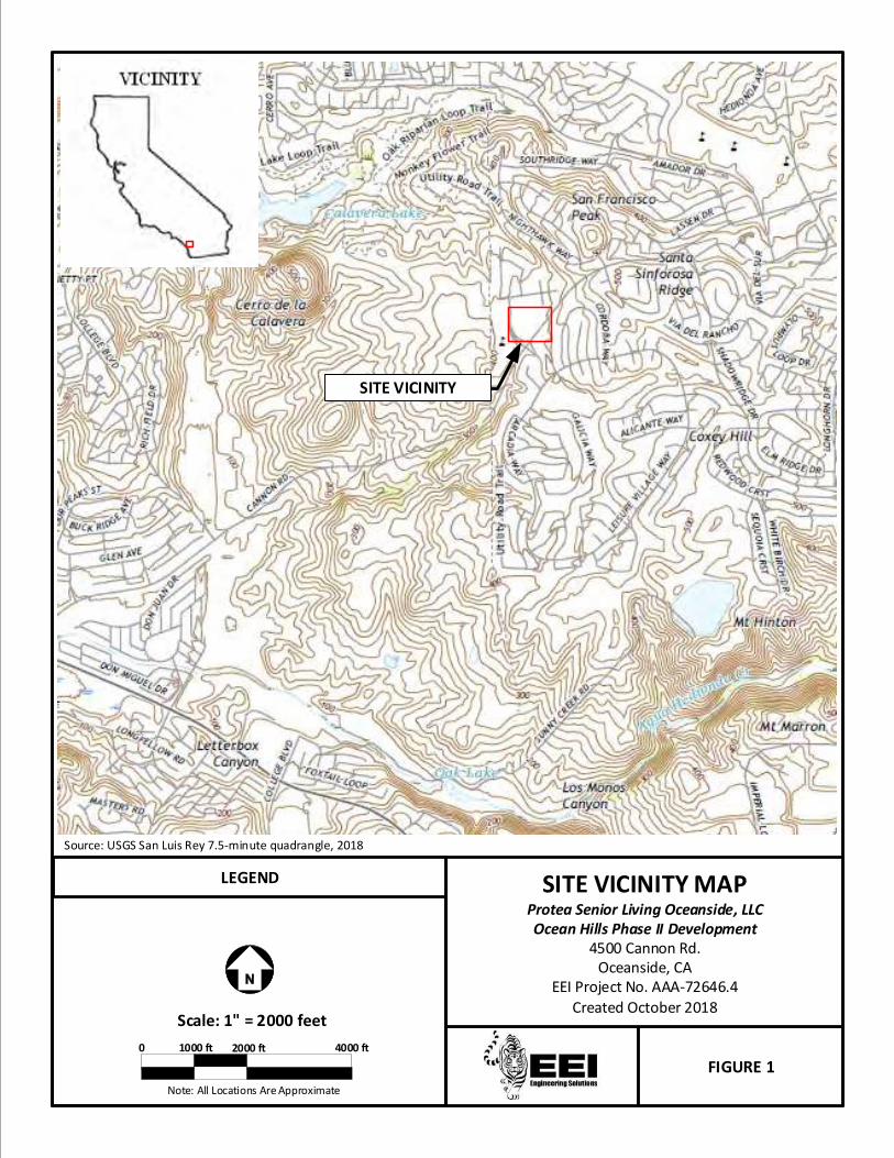
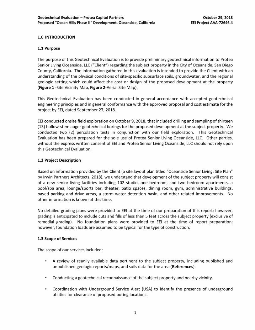
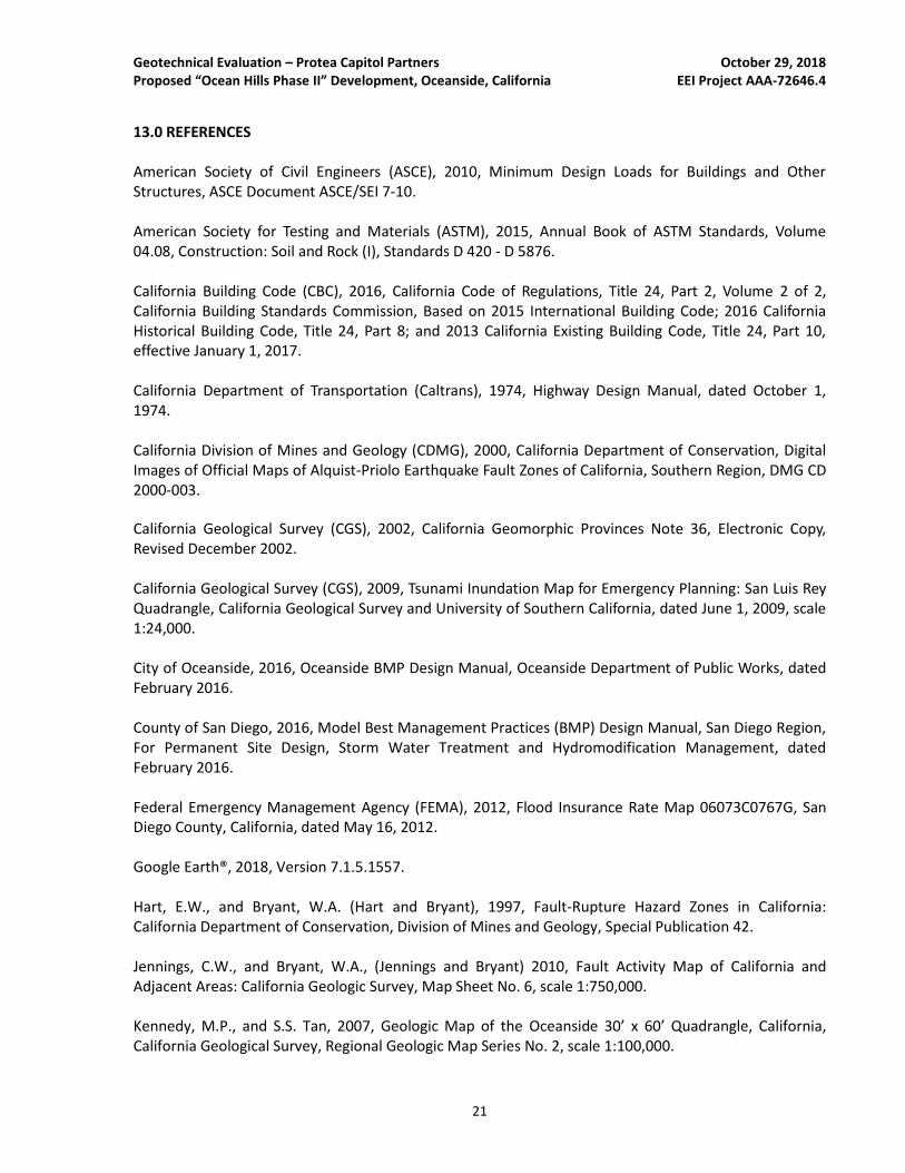
FIGURE 1
SITE VICINITY MAPProtea Senior Living Oceanside, LLCOcean Hills Phase II Development
4500 Cannon Rd.Oceanside, CA
EEI Project No. AAA-72646.4
Created October 2018Scale: 1" = 2000 feet
Note: All Locations Are Approximate
2000 ft
Source: USGS San Luis Rey 7.5-minute quadrangle, 2018
LEGEND
4000 ft1000 ft0
SITE VICINITY
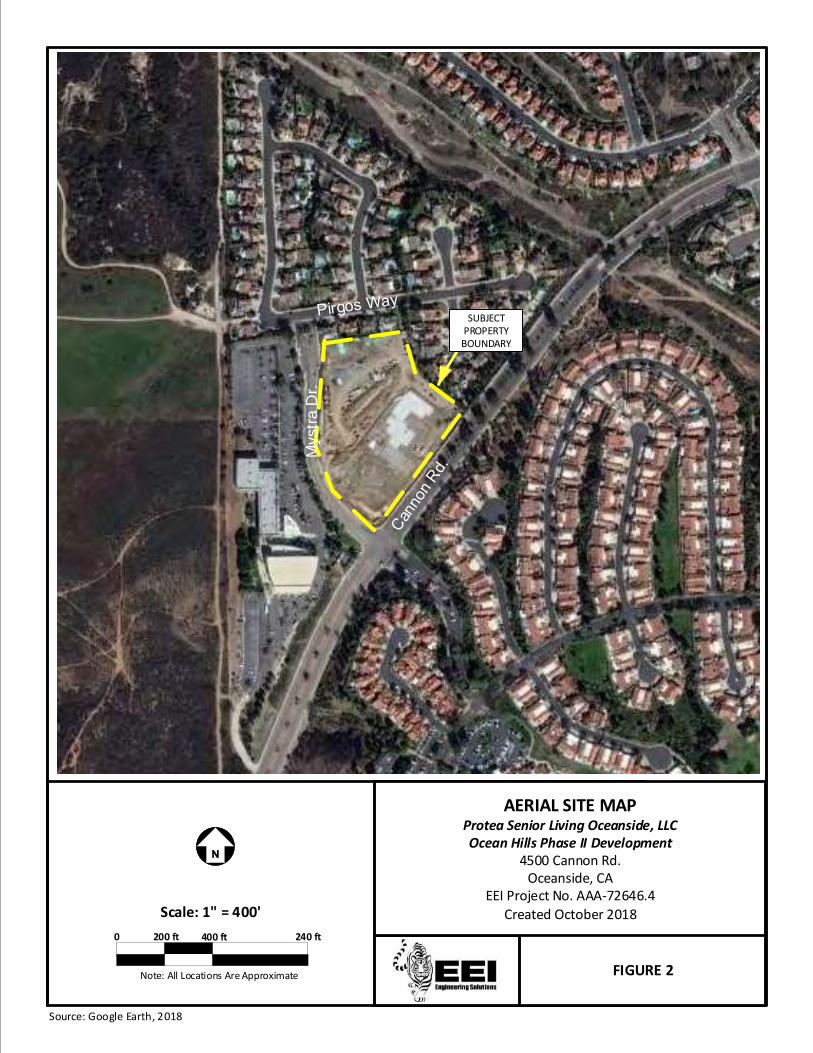
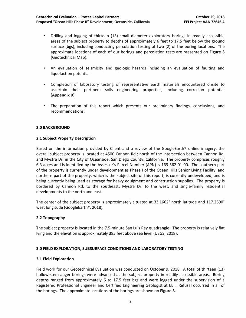
FIGURE 2
AERIAL SITE MAPProtea Senior Living Oceanside, LLCOcean Hills Phase II Development
4500 Cannon Rd.Oceanside, CA
EEI Project No. AAA-72646.4
Created October 2018
Source: Google Earth, 2018
Scale: 1" = 400'
Note: All Locations Are Approximate
400 ft 240 ft200 ft0
SUBJECT PROPERTY
BOUNDARY
Mystr
a D
r.
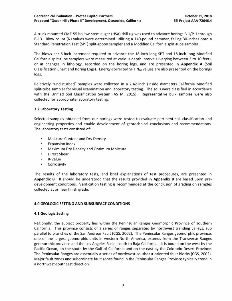
Source: Irwin Partners Architects, Site Plan, 2018
FIGURE 3Scale: 1" = 80'
Note: All Locations Are Approximate
Approximate Boring Locations with Total Depth (TD)B-2
LEGENDGEOTECHNICAL MAPProtea Senior Living Oceanside, LLCOcean Hills Phase II Development
4500 Cannon Rd.Oceanside, CA
EEI Project No. AAA-72646.4
Created October 2018
80 FT0 FT 160 FT
Approximate Boring/Percolation Test Location with Total Depth (TD)B-1
B-2TD = 9' Af
Qop6
Af
Qop6
B-3TD = 6'
B-5TD = 8'
B-1TD = 15.5'
B-4TD = 9'
B-7TD = 11'
B-6TD = 16'
B-8TD = 15'
B-10TD = 8'
B-11TD = 10.5'
B-13TD = 15'
B-9TD = 17.5'
B-12TD = 13'
Af
Af
Af
Af
Af
Af
Af
Ts
Ts
Kg
Kg
Kg
Ts
Kg
Undocumented Artificial Fill
Approximate Location of Eocene Santiago Formation; Circled where buried
Approximate Location of Cretaceous Granitics; Circled where buried
Approximate Subsurface Geologic Contact
Af
Kg
Kg
Geotechnical Evaluation – Protea Capitol Partners October 29, 2018 Proposed “Ocean Hills Phase II” Development, Oceanside, California EEI Project AAA-72646.4
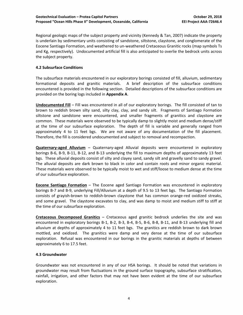
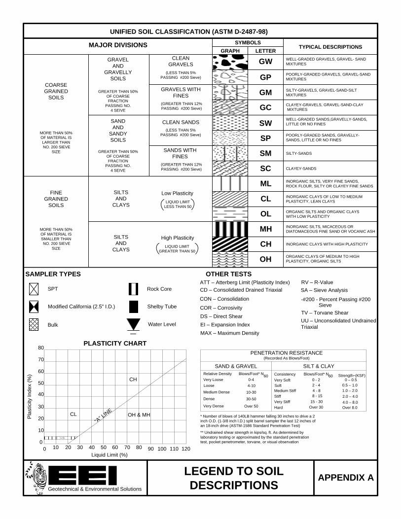
APPENDIX A
SOIL CLASSIFICATION CHART AND BORING LOGS
South Melrose
Drive
SYMBOLS
GRAPH LETTERTYPICAL DESCRIPTIONSMAJOR DIVISIONS
GW
GP
GM
GC
SW
SP
SM
SC
ML
CL
OL
MH
CH
OH
COARSE
GRAINED
SOILS
GRAVEL
AND
GRAVELLY
SOILS
CLEAN
GRAVELS
(LESS THAN 5%
PASSING #200 Sieve)
GRAVELS WITH
FINESGREATER THAN 50%
OF COARSE
FRACTION
PASSING NO.
4 SEIVE
WELL-GRADED GRAVELS, GRAVEL- SAND
MIXTURES
POORLY-GRADED GRAVELS, GRAVEL-SAND
MIXTURES
SILTY-GRAVELS, GRAVEL-SAND-SILT
MIXTURES
CLAYEY-GRAVELS, GRAVEL-SAND-CLAY
MIXTURES
WELL-GRADED SANDS,GRAVELLY-SANDS,
LITTLE OR NO FINESCLEAN SANDS
SANDS WITH
FINES
SAND
AND
SANDY
SOILS
GREATER THAN 50%
OF COARSE
FRACTION
PASSING NO.
4 SEIVE
MORE THAN 50%
OF MATERIAL IS
LARGER THAN
NO. 200 SIEVE
SIZE
POORLY-GRADED SANDS, GRAVELLY-
SANDS, LITTLE OR NO FINES
SILTY-SANDS
CLAYEY-SANDS
FINE
GRAINED
SOILS
SILTS
AND
CLAYSLIQUID LIMIT
LESS THAN 50
SILTS
AND
CLAYSLIQUID LIMIT
GREATER THAN 50
MORE THAN 50%
OF MATERIAL IS
SMALLER THAN
NO. 200 SIEVE
SIZE
INORGANIC SILTS, VERY FINE SANDS,
ROCK FLOUR, SILTY OR CLAYEY FINE SANDS
INORGANIC CLAYS OF LOW TO MEDIUM
PLASTICITY, LEAN CLAYS
ORGANIC SILTS AND ORGANIC CLAYS
WITH LOW PLASTICITY
INORGANIC SILTS, MICACEOUS OR
DIATOMACEOUS FINE SAND OR VOCANIC ASH
INORGANIC CLAYS WITH HIGH PLASTICITY
ORGANIC CLAYS OF MEDIUM TO HIGH
PLASTICITY, ORGANIC SILTS
SAMPLER TYPES
SPT
Modified California (2.5" I.D.)
Bulk
Shelby Tube
Rock Core
OTHER TESTS
COR – Corrosivity
CD – Consolidated Drained Triaxial
CON – Consolidation
DS – Direct Shear
RV – R-Value
SA – Sieve Analysis
ATT – Atterberg Limit (Plasticity Index)
TV – Torvane Shear
UU – Unconsolidated Undrained
Triaxial
PLASTICITY CHART
Pla
sticity In
de
x (
%)
0
0Liquid Limit (%)
10
20
30
40
50
60
70
80
10 20 30 40 50 60 70 80 90 100 110 120
CL-ML
CL
“A” L
INE
CH
OH & MH
Water Level
PENETRATION RESISTANCE(Recorded As Blows/Foot)
SAND & GRAVEL SILT & CLAY
Relative Density
Very Loose
Loose
Medium Dense
Dense
Very Dense
Blows/Foot* N
0-4
4-10
10-30
30-50
Over 50
Consistency
Very Soft
Soft
Medium Stiff
Stiff
Very Stiff
Blows/Foot* N
0 - 2
2 - 4
4 - 8
Over 30
8 - 15
Hard
15 - 30
Strength**(KSF)0 – 0.5
0.5 – 1.0
1.0 – 2.0
Over 8.0
2.0 – 4.0
4.0 – 8.0
* Number of blows of 140LB hammer falling 30 inches to drive a 2
inch O.D. (1-3/8 inch I.D.) split barrel sampler the last 12 inches of
an 18-inch drive (ASTM-1586 Standard Penetration Test)
60 60
** Undrained shear strength in kips/sq. ft. As determined by
laboratory testing or approximated by the standard penetration
test, pocket penetrometer, torvane, or visual observation
UNIFIED SOIL CLASSIFICATION (ASTM D-2487-98)
Geotechnical & Environmental Solutions
LEGEND TO SOIL
DESCRIPTIONSAPPENDIX A
EI – Expansion Index
MAX – Maximum Density
-#200 - Percent Passing #200 Sieve
High Plasticity
Low Plasticity
(GREATER THAN 12%
PASSING #200 Sieve)
(LESS THAN 5%
PASSING #200 Sieve)
(GREATER THAN 12%
PASSING #200 Sieve)
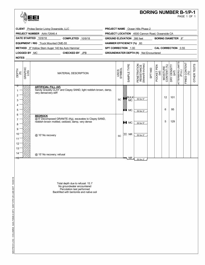
BULKMC
MC
MC
NR
NR
12
6
5
101
95
129
50 for 5"
50 for 3"
50 for 5"
50 for 2"
50 for 2"
SC
SC
ARTIFICIAL FILL (Af)Sandy Gravelly CLAY and Clayey SAND, light reddish-brown, damp,very dense/very stiff
BEDROCK@ 6' Decomposed GRANITE (Kg), excavates to Clayey SAND,reddish-brown mottled, oxidized, damp, very dense
@ 10' No recovery
@ 15' No recovery; refusal
Total depth due to refusal: 15.1'No groundwater encountered
Percolation test performedBackfilled with bentonite and native soil
COMPLETED 10/9/18DATE STARTED 10/9/18
LOGGED BY MC
GROUND ELEVATION 386 feet
EQUIPMENT / RIG Truck Mounted CME-55
METHOD 8" Hollow Stem Auger 140 lbs Auto Hammer
CHECKED BY JPB
HAMMER EFFICIENCY (%) 60
SPT CORRECTION 1.00 CAL CORRECTION 0.55
GROUNDWATER DEPTH (ft) Not Encountered
BORING DIAMETER 8"
NOTES
GR
AP
HIC
LOG
SA
MP
LE T
YP
E
MO
IST
UR
EC
ON
TE
NT
(%
)
DR
Y D
EN
SIT
Y(p
cf)
PE
NE
TR
AT
ION
RE
SIS
TA
NC
E(b
low
s/6-
inch
es)
FIN
ES
CO
NT
EN
T(%
)
DE
PT
H(f
t)
0
1
2
3
4
5
6
7
8
9
10
11
12
13
14
15
OT
HE
R T
ES
TS
SP
T N
60
PO
CK
ET
PE
N(t
sf)
US
CS
SY
MB
OL
AT
TE
RB
ER
G L
IMIT
S(P
I:LL)
MATERIAL DESCRIPTION
PAGE 1 OF 1BORING NUMBER B-1/P-1
PROJECT NAME Ocean Hills Phase 2
PROJECT LOCATION 4500 Cannon Road, Oceanside CA
CLIENT Protea Senior Living Oceanside, LLC
PROJECT NUMBER AAA-72646.4
GE
OT
EC
H L
OG
- C
OLU
MN
S
AA
A-7
2646
.4.G
PJ
GIN
T S
TD
US
LA
B.G
DT
10/
25/
18
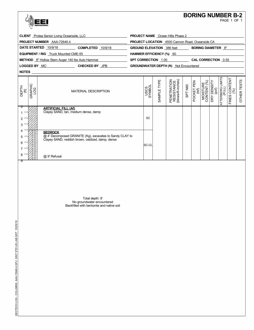
SC
SC-CL
ARTIFICIAL FILL (Af)Clayey SAND, tan, medium dense, damp
BEDROCK@ 4' Decomposed GRANITE (Kg), excavates to Sandy CLAY toClayey SAND, reddish brown, oxidized, damp, dense
@ 9' Refusal
Total depth: 9'No groundwater encountered
Backfilled with bentonite and native soil
COMPLETED 10/9/18DATE STARTED 10/9/18
LOGGED BY MC
GROUND ELEVATION 386 feet
EQUIPMENT / RIG Truck Mounted CME-55
METHOD 8" Hollow Stem Auger 140 lbs Auto Hammer
CHECKED BY JPB
HAMMER EFFICIENCY (%) 60
SPT CORRECTION 1.00 CAL CORRECTION 0.55
GROUNDWATER DEPTH (ft) Not Encountered
BORING DIAMETER 8"
NOTES
GR
AP
HIC
LOG
SA
MP
LE T
YP
E
MO
IST
UR
EC
ON
TE
NT
(%
)
DR
Y D
EN
SIT
Y(p
cf)
PE
NE
TR
AT
ION
RE
SIS
TA
NC
E(b
low
s/6-
inch
es)
FIN
ES
CO
NT
EN
T(%
)
DE
PT
H(f
t)
0
1
2
3
4
5
6
7
8
9
OT
HE
R T
ES
TS
SP
T N
60
PO
CK
ET
PE
N(t
sf)
US
CS
SY
MB
OL
AT
TE
RB
ER
G L
IMIT
S(P
I:LL)
MATERIAL DESCRIPTION
PAGE 1 OF 1BORING NUMBER B-2
PROJECT NAME Ocean Hills Phase 2
PROJECT LOCATION 4500 Cannon Road, Oceanside CA
CLIENT Protea Senior Living Oceanside, LLC
PROJECT NUMBER AAA-72646.4
GE
OT
EC
H L
OG
- C
OLU
MN
S
AA
A-7
2646
.4.G
PJ
GIN
T S
TD
US
LA
B.G
DT
10/
25/
18
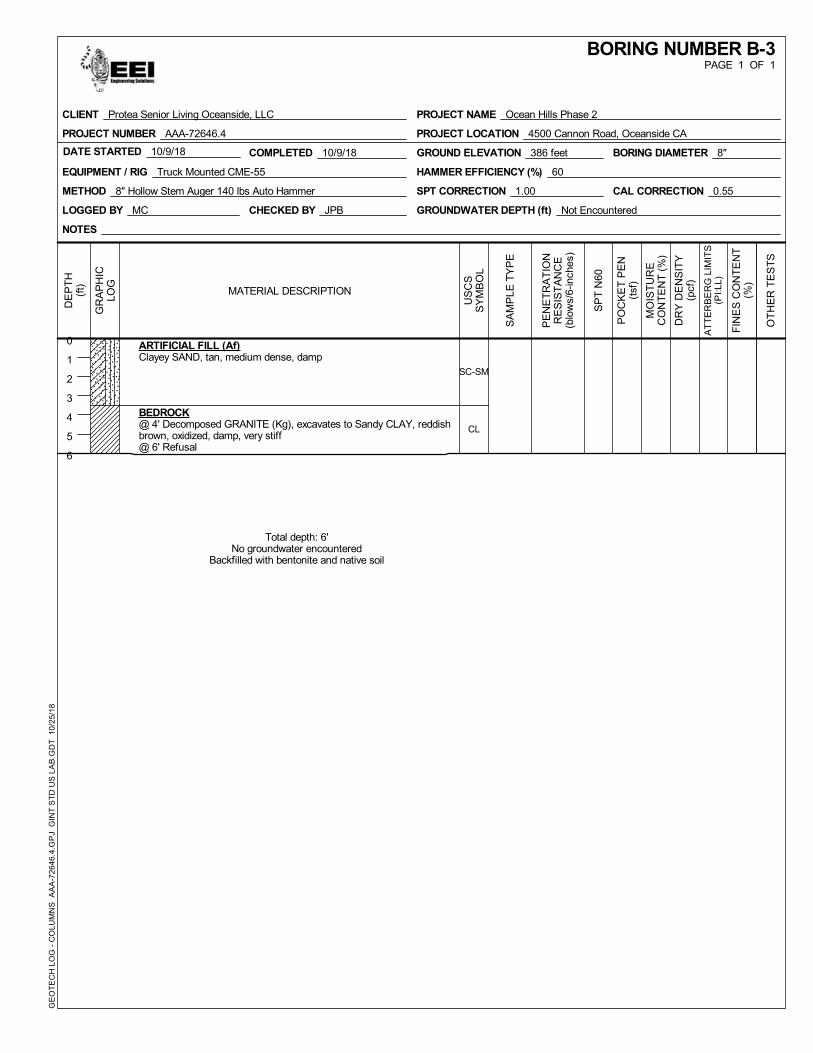
SC-SM
CL
ARTIFICIAL FILL (Af)Clayey SAND, tan, medium dense, damp
BEDROCK@ 4' Decomposed GRANITE (Kg), excavates to Sandy CLAY, reddishbrown, oxidized, damp, very stiff@ 6' Refusal
Total depth: 6'No groundwater encountered
Backfilled with bentonite and native soil
COMPLETED 10/9/18DATE STARTED 10/9/18
LOGGED BY MC
GROUND ELEVATION 386 feet
EQUIPMENT / RIG Truck Mounted CME-55
METHOD 8" Hollow Stem Auger 140 lbs Auto Hammer
CHECKED BY JPB
HAMMER EFFICIENCY (%) 60
SPT CORRECTION 1.00 CAL CORRECTION 0.55
GROUNDWATER DEPTH (ft) Not Encountered
BORING DIAMETER 8"
NOTES
GR
AP
HIC
LOG
SA
MP
LE T
YP
E
MO
IST
UR
EC
ON
TE
NT
(%
)
DR
Y D
EN
SIT
Y(p
cf)
PE
NE
TR
AT
ION
RE
SIS
TA
NC
E(b
low
s/6-
inch
es)
FIN
ES
CO
NT
EN
T(%
)
DE
PT
H(f
t)
0
1
2
3
4
5
6
OT
HE
R T
ES
TS
SP
T N
60
PO
CK
ET
PE
N(t
sf)
US
CS
SY
MB
OL
AT
TE
RB
ER
G L
IMIT
S(P
I:LL)
MATERIAL DESCRIPTION
PAGE 1 OF 1BORING NUMBER B-3
PROJECT NAME Ocean Hills Phase 2
PROJECT LOCATION 4500 Cannon Road, Oceanside CA
CLIENT Protea Senior Living Oceanside, LLC
PROJECT NUMBER AAA-72646.4
GE
OT
EC
H L
OG
- C
OLU
MN
S
AA
A-7
2646
.4.G
PJ
GIN
T S
TD
US
LA
B.G
DT
10/
25/
18
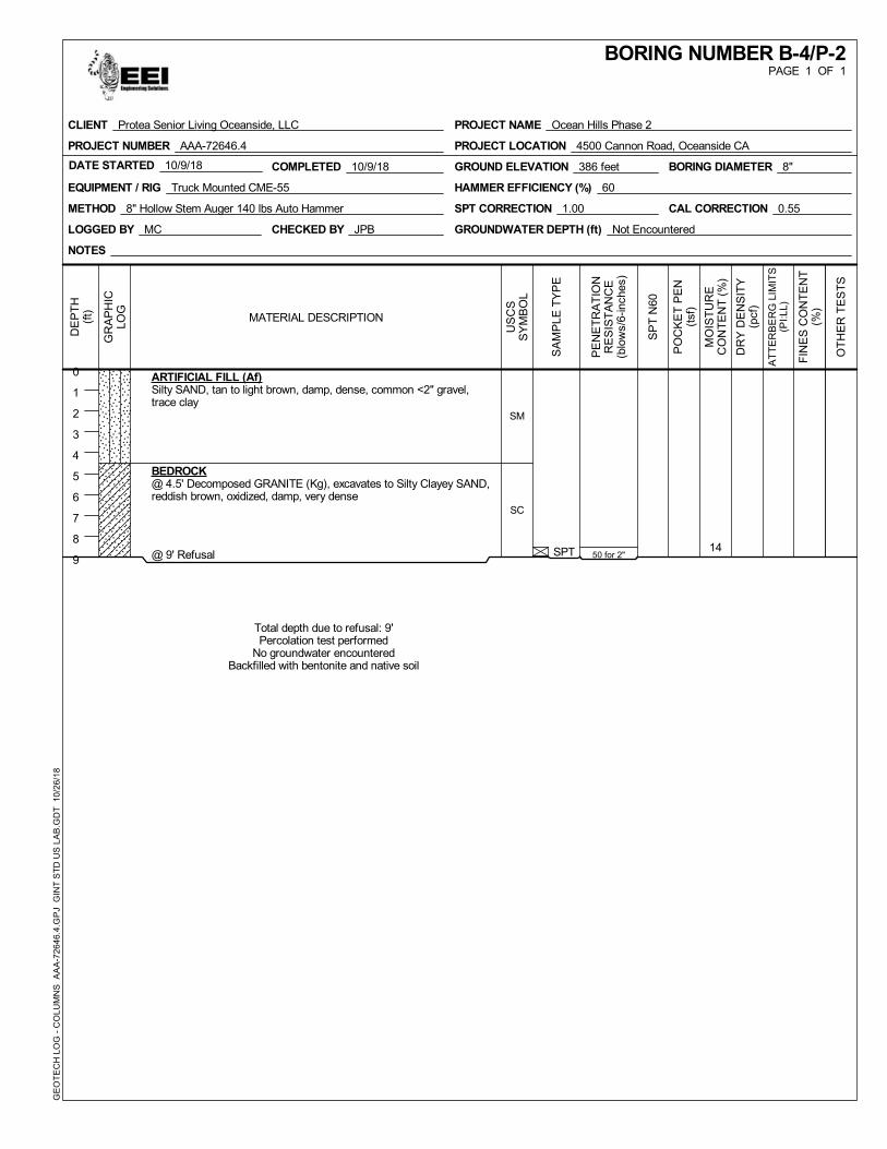
SPT 1450 for 2"
SM
SC
ARTIFICIAL FILL (Af)Silty SAND, tan to light brown, damp, dense, common <2" gravel,trace clay
BEDROCK@ 4.5' Decomposed GRANITE (Kg), excavates to Silty Clayey SAND,reddish brown, oxidized, damp, very dense
@ 9' Refusal
Total depth due to refusal: 9'Percolation test performed
No groundwater encounteredBackfilled with bentonite and native soil
COMPLETED 10/9/18DATE STARTED 10/9/18
LOGGED BY MC
GROUND ELEVATION 386 feet
EQUIPMENT / RIG Truck Mounted CME-55
METHOD 8" Hollow Stem Auger 140 lbs Auto Hammer
CHECKED BY JPB
HAMMER EFFICIENCY (%) 60
SPT CORRECTION 1.00 CAL CORRECTION 0.55
GROUNDWATER DEPTH (ft) Not Encountered
BORING DIAMETER 8"
NOTES
GR
AP
HIC
LOG
SA
MP
LE T
YP
E
MO
IST
UR
EC
ON
TE
NT
(%
)
DR
Y D
EN
SIT
Y(p
cf)
PE
NE
TR
AT
ION
RE
SIS
TA
NC
E(b
low
s/6-
inch
es)
FIN
ES
CO
NT
EN
T(%
)
DE
PT
H(f
t)
0
1
2
3
4
5
6
7
8
9
OT
HE
R T
ES
TS
SP
T N
60
PO
CK
ET
PE
N(t
sf)
US
CS
SY
MB
OL
AT
TE
RB
ER
G L
IMIT
S(P
I:LL)
MATERIAL DESCRIPTION
PAGE 1 OF 1BORING NUMBER B-4/P-2
PROJECT NAME Ocean Hills Phase 2
PROJECT LOCATION 4500 Cannon Road, Oceanside CA
CLIENT Protea Senior Living Oceanside, LLC
PROJECT NUMBER AAA-72646.4
GE
OT
EC
H L
OG
- C
OLU
MN
S
AA
A-7
2646
.4.G
PJ
GIN
T S
TD
US
LA
B.G
DT
10/
26/
18
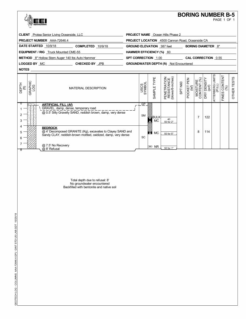
BULKMC
MC
NR
7
8
122
114
4050 for 2"
50 for 5"
50 for 1"
GP
SM
SC
ARTIFICIAL FILL (Af)GRAVEL, damp, dense, temporary road@ 0.5' Silty Gravelly SAND, reddish brown, damp, very dense
BEDROCK@ 4' Decomposed GRANITE (Kg), excavates to Clayey SAND andSandy CLAY, reddish-brown mottled, oxidized, damp, very dense
@ 7.5' No Recovery@ 8' Refusal
Total depth due to refusal: 8'No groundwater encountered
Backfilled with bentonite and native soil
COMPLETED 10/9/18DATE STARTED 10/9/18
LOGGED BY MC
GROUND ELEVATION 387 feet
EQUIPMENT / RIG Truck Mounted CME-55
METHOD 8" Hollow Stem Auger 140 lbs Auto Hammer
CHECKED BY JPB
HAMMER EFFICIENCY (%) 60
SPT CORRECTION 1.00 CAL CORRECTION 0.55
GROUNDWATER DEPTH (ft) Not Encountered
BORING DIAMETER 8"
NOTES
GR
AP
HIC
LOG
SA
MP
LE T
YP
E
MO
IST
UR
EC
ON
TE
NT
(%
)
DR
Y D
EN
SIT
Y(p
cf)
PE
NE
TR
AT
ION
RE
SIS
TA
NC
E(b
low
s/6-
inch
es)
FIN
ES
CO
NT
EN
T(%
)
DE
PT
H(f
t)
0
1
2
3
4
5
6
7
8
OT
HE
R T
ES
TS
SP
T N
60
PO
CK
ET
PE
N(t
sf)
US
CS
SY
MB
OL
AT
TE
RB
ER
G L
IMIT
S(P
I:LL)
MATERIAL DESCRIPTION
PAGE 1 OF 1BORING NUMBER B-5
PROJECT NAME Ocean Hills Phase 2
PROJECT LOCATION 4500 Cannon Road, Oceanside CA
CLIENT Protea Senior Living Oceanside, LLC
PROJECT NUMBER AAA-72646.4
GE
OT
EC
H L
OG
- C
OLU
MN
S
AA
A-7
2646
.4.G
PJ
GIN
T S
TD
US
LA
B.G
DT
10/
25/
18
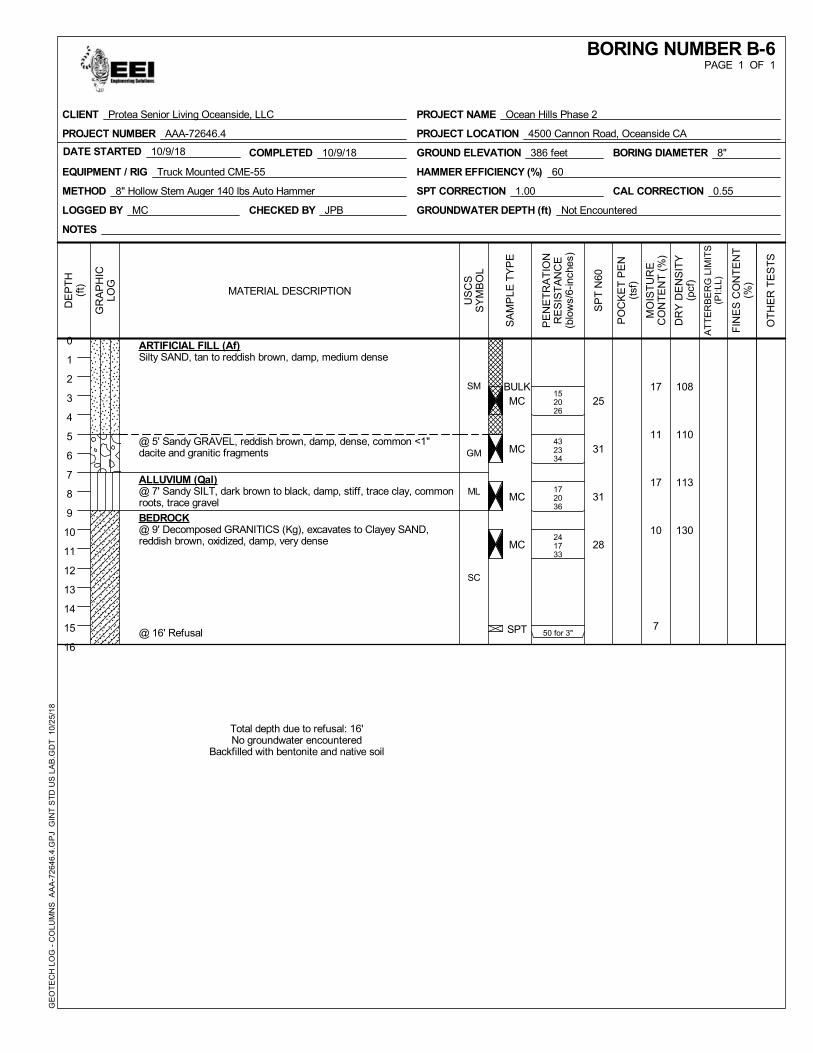
BULKMC
MC
MC
MC
SPT
17
11
17
10
7
108
110
113
130
152026
432334
172036
241733
50 for 3"
25
31
31
28
SM
GM
ML
SC
ARTIFICIAL FILL (Af)Silty SAND, tan to reddish brown, damp, medium dense
@ 5' Sandy GRAVEL, reddish brown, damp, dense, common <1"dacite and granitic fragments
ALLUVIUM (Qal)@ 7' Sandy SILT, dark brown to black, damp, stiff, trace clay, commonroots, trace gravel
BEDROCK@ 9' Decomposed GRANITICS (Kg), excavates to Clayey SAND,reddish brown, oxidized, damp, very dense
@ 16' Refusal
Total depth due to refusal: 16'No groundwater encountered
Backfilled with bentonite and native soil
COMPLETED 10/9/18DATE STARTED 10/9/18
LOGGED BY MC
GROUND ELEVATION 386 feet
EQUIPMENT / RIG Truck Mounted CME-55
METHOD 8" Hollow Stem Auger 140 lbs Auto Hammer
CHECKED BY JPB
HAMMER EFFICIENCY (%) 60
SPT CORRECTION 1.00 CAL CORRECTION 0.55
GROUNDWATER DEPTH (ft) Not Encountered
BORING DIAMETER 8"
NOTES
GR
AP
HIC
LOG
SA
MP
LE T
YP
E
MO
IST
UR
EC
ON
TE
NT
(%
)
DR
Y D
EN
SIT
Y(p
cf)
PE
NE
TR
AT
ION
RE
SIS
TA
NC
E(b
low
s/6-
inch
es)
FIN
ES
CO
NT
EN
T(%
)
DE
PT
H(f
t)
0
1
2
3
4
5
6
7
8
9
10
11
12
13
14
15
16
OT
HE
R T
ES
TS
SP
T N
60
PO
CK
ET
PE
N(t
sf)
US
CS
SY
MB
OL
AT
TE
RB
ER
G L
IMIT
S(P
I:LL)
MATERIAL DESCRIPTION
PAGE 1 OF 1BORING NUMBER B-6
PROJECT NAME Ocean Hills Phase 2
PROJECT LOCATION 4500 Cannon Road, Oceanside CA
CLIENT Protea Senior Living Oceanside, LLC
PROJECT NUMBER AAA-72646.4
GE
OT
EC
H L
OG
- C
OLU
MN
S
AA
A-7
2646
.4.G
PJ
GIN
T S
TD
US
LA
B.G
DT
10/
25/
18
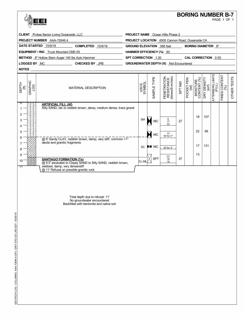
MC
MC
MC
SPT
18
22
17
13
107
99
131
61732
1350 for 2"
50 for 2"
231819
27
37
SM
SC
CL-ML
ARTIFICIAL FILL (Af)Silty SAND, tan to reddish brown, damp, medium dense, trace gravel
@ 6' Sandy CLAY, reddish brown, damp, very stiff, common <1"dacite and granitic fragments
SANTIAGO FORMATION (Ts)@ 9.5' excavates to Clayey SAND to Silty SAND, reddish brown,oxidized, damp, very dense/stiff@ 11' Refusal on possible granitic rock
Total depth due to refusal: 11'No groundwater encountered
Backfilled with bentonite and native soil
COMPLETED 10/9/18DATE STARTED 10/9/18
LOGGED BY MC
GROUND ELEVATION 388 feet
EQUIPMENT / RIG Truck Mounted CME-55
METHOD 8" Hollow Stem Auger 140 lbs Auto Hammer
CHECKED BY JPB
HAMMER EFFICIENCY (%) 60
SPT CORRECTION 1.00 CAL CORRECTION 0.55
GROUNDWATER DEPTH (ft) Not Encountered
BORING DIAMETER 8"
NOTES
GR
AP
HIC
LOG
SA
MP
LE T
YP
E
MO
IST
UR
EC
ON
TE
NT
(%
)
DR
Y D
EN
SIT
Y(p
cf)
PE
NE
TR
AT
ION
RE
SIS
TA
NC
E(b
low
s/6-
inch
es)
FIN
ES
CO
NT
EN
T(%
)
DE
PT
H(f
t)
0
1
2
3
4
5
6
7
8
9
10
11
OT
HE
R T
ES
TS
SP
T N
60
PO
CK
ET
PE
N(t
sf)
US
CS
SY
MB
OL
AT
TE
RB
ER
G L
IMIT
S(P
I:LL)
MATERIAL DESCRIPTION
PAGE 1 OF 1BORING NUMBER B-7
PROJECT NAME Ocean Hills Phase 2
PROJECT LOCATION 4500 Cannon Road, Oceanside CA
CLIENT Protea Senior Living Oceanside, LLC
PROJECT NUMBER AAA-72646.4
GE
OT
EC
H L
OG
- C
OLU
MN
S
AA
A-7
2646
.4.G
PJ
GIN
T S
TD
US
LA
B.G
DT
10/
26/
18
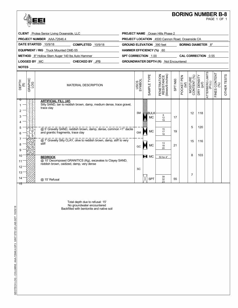
BULKMC
MC
MC
MC
SPT
12
5
15
8
7
118
120
116
103
81219
151718
131820
50 for 4"
393223
17
19
21
55
SM
GM
GC
SC
ARTIFICIAL FILL (Af)Silty SAND, tan to reddish brown, damp, medium dense, trace gravel,trace clay
@ 5' Gravelly SAND, reddish brown, damp, dense, common <1" daciteand granitic fragments, trace clay
@ 7' Gravelly Silty CLAY, olive to reddish brown, damp, stiff to verystiff
BEDROCK@ 10' Decomposed GRANITICS (Kg), excavates to Clayey SAND,reddish brown, oxidized, damp, very dense
@ 15' Refusal
Total depth due to refusal: 15'No groundwater encountered
Backfilled with bentonite and native soil
COMPLETED 10/9/18DATE STARTED 10/9/18
LOGGED BY MC
GROUND ELEVATION 390 feet
EQUIPMENT / RIG Truck Mounted CME-55
METHOD 8" Hollow Stem Auger 140 lbs Auto Hammer
CHECKED BY JPB
HAMMER EFFICIENCY (%) 60
SPT CORRECTION 1.00 CAL CORRECTION 0.55
GROUNDWATER DEPTH (ft) Not Encountered
BORING DIAMETER 8"
NOTES
GR
AP
HIC
LOG
SA
MP
LE T
YP
E
MO
IST
UR
EC
ON
TE
NT
(%
)
DR
Y D
EN
SIT
Y(p
cf)
PE
NE
TR
AT
ION
RE
SIS
TA
NC
E(b
low
s/6-
inch
es)
FIN
ES
CO
NT
EN
T(%
)
DE
PT
H(f
t)
0
1
2
3
4
5
6
7
8
9
10
11
12
13
14
15
OT
HE
R T
ES
TS
SP
T N
60
PO
CK
ET
PE
N(t
sf)
US
CS
SY
MB
OL
AT
TE
RB
ER
G L
IMIT
S(P
I:LL)
MATERIAL DESCRIPTION
PAGE 1 OF 1BORING NUMBER B-8
PROJECT NAME Ocean Hills Phase 2
PROJECT LOCATION 4500 Cannon Road, Oceanside CA
CLIENT Protea Senior Living Oceanside, LLC
PROJECT NUMBER AAA-72646.4
GE
OT
EC
H L
OG
- C
OLU
MN
S
AA
A-7
2646
.4.G
PJ
GIN
T S
TD
US
LA
B.G
DT
10/
25/
18
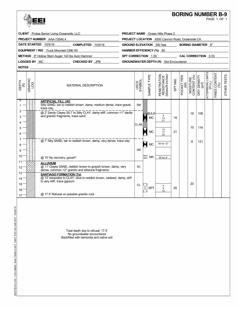
BULKMC
MC
MC
NR
SPT
18
15
8
20
106
116
121
91321
131722
50 for 12"
50 for 4"
58
12
19
21
20
SM
CL-ML
SM
SC
CL
ARTIFICIAL FILL (Af)Silty SAND, tan to reddish brown, damp, medium dense, trace gravel,trace clay
@ 2' Sandy Clayey SILT to Silty CLAY, damp stiff, common <1" daciteand granitic fragments, trace sand
@ 7' Silty SAND, tan to reddish brown, damp, very dense, trace clay
@ 10' No recovery; gravel?
ALLUVIUM@ 11' Clayey SAND, reddish brown to grayish-brown, damp, verydense, common <2" granitic and siltstone fragments
SANTIAGO FORMATION (Ts)@ 13' excavates to CLAY, olive to reddish brown, oxidized, damp, stiffto very stiff, trace gypsum
@ 17.5' Refusal on possible granitic rock
Total depth due to refusal: 17.5'No groundwater encountered
Backfilled with bentonite and native soil
COMPLETED 10/9/18DATE STARTED 10/9/18
LOGGED BY MC
GROUND ELEVATION 390 feet
EQUIPMENT / RIG Truck Mounted CME-55
METHOD 8" Hollow Stem Auger 140 lbs Auto Hammer
CHECKED BY JPB
HAMMER EFFICIENCY (%) 60
SPT CORRECTION 1.00 CAL CORRECTION 0.55
GROUNDWATER DEPTH (ft) Not Encountered
BORING DIAMETER 8"
NOTES
GR
AP
HIC
LOG
SA
MP
LE T
YP
E
MO
IST
UR
EC
ON
TE
NT
(%
)
DR
Y D
EN
SIT
Y(p
cf)
PE
NE
TR
AT
ION
RE
SIS
TA
NC
E(b
low
s/6-
inch
es)
FIN
ES
CO
NT
EN
T(%
)
DE
PT
H(f
t)
0
1
2
3
4
5
6
7
8
9
10
11
12
13
14
15
16
17
OT
HE
R T
ES
TS
SP
T N
60
PO
CK
ET
PE
N(t
sf)
US
CS
SY
MB
OL
AT
TE
RB
ER
G L
IMIT
S(P
I:LL)
MATERIAL DESCRIPTION
PAGE 1 OF 1BORING NUMBER B-9
PROJECT NAME Ocean Hills Phase 2
PROJECT LOCATION 4500 Cannon Road, Oceanside CA
CLIENT Protea Senior Living Oceanside, LLC
PROJECT NUMBER AAA-72646.4
GE
OT
EC
H L
OG
- C
OLU
MN
S
AA
A-7
2646
.4.G
PJ
GIN
T S
TD
US
LA
B.G
DT
10/
26/
18
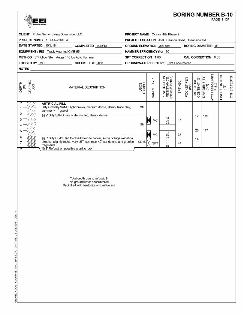
MC
MC
SPT
12
20
14
119
117
163545
122535412123
44
33
44
SM
SM
CL-ML
ARTIFICIAL FILLSilty Gravelly SAND, light brown, medium dense, damp, trace clay,common <1" gravel
@ 2' Silty SAND, tan white mottled, damp, dense
@ 6' Silty CLAY, tan to olive brown to brown, some orange oxidationstreaks, slightly moist, very stiff, common <2" sandstone and graniticfragments@ 8' Refusal on possible granitic rock
Total depth due to refusal: 8'No groundwater encountered
Backfilled with bentonite and native soil
COMPLETED 10/9/18DATE STARTED 10/9/18
LOGGED BY MC
GROUND ELEVATION 391 feet
EQUIPMENT / RIG Truck Mounted CME-55
METHOD 8" Hollow Stem Auger 140 lbs Auto Hammer
CHECKED BY JPB
HAMMER EFFICIENCY (%) 60
SPT CORRECTION 1.00 CAL CORRECTION 0.55
GROUNDWATER DEPTH (ft) Not Encountered
BORING DIAMETER 8"
NOTES
GR
AP
HIC
LOG
SA
MP
LE T
YP
E
MO
IST
UR
EC
ON
TE
NT
(%
)
DR
Y D
EN
SIT
Y(p
cf)
PE
NE
TR
AT
ION
RE
SIS
TA
NC
E(b
low
s/6-
inch
es)
FIN
ES
CO
NT
EN
T(%
)
DE
PT
H(f
t)
0
1
2
3
4
5
6
7
8
OT
HE
R T
ES
TS
SP
T N
60
PO
CK
ET
PE
N(t
sf)
US
CS
SY
MB
OL
AT
TE
RB
ER
G L
IMIT
S(P
I:LL)
MATERIAL DESCRIPTION
PAGE 1 OF 1BORING NUMBER B-10
PROJECT NAME Ocean Hills Phase 2
PROJECT LOCATION 4500 Cannon Road, Oceanside CA
CLIENT Protea Senior Living Oceanside, LLC
PROJECT NUMBER AAA-72646.4
GE
OT
EC
H L
OG
- C
OLU
MN
S
AA
A-7
2646
.4.G
PJ
GIN
T S
TD
US
LA
B.G
DT
10/
25/
18
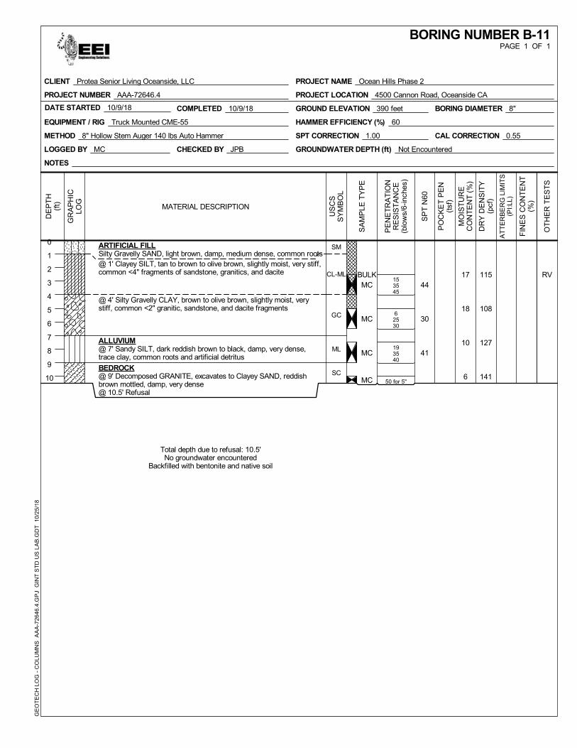
BULKMC
MC
MC
MC
17
18
10
6
115
108
127
141
153545
62530
193540
50 for 5"
RV44
30
41
SM
CL-ML
GC
ML
SC
ARTIFICIAL FILLSilty Gravelly SAND, light brown, damp, medium dense, common roots@ 1' Clayey SILT, tan to brown to olive brown, slightly moist, very stiff,common <4" fragments of sandstone, granitics, and dacite
@ 4' Silty Gravelly CLAY, brown to olive brown, slightly moist, verystiff, common <2" granitic, sandstone, and dacite fragments
ALLUVIUM@ 7' Sandy SILT, dark reddish brown to black, damp, very dense,trace clay, common roots and artificial detritus
BEDROCK@ 9' Decomposed GRANITE, excavates to Clayey SAND, reddishbrown mottled, damp, very dense@ 10.5' Refusal
Total depth due to refusal: 10.5'No groundwater encountered
Backfilled with bentonite and native soil
COMPLETED 10/9/18DATE STARTED 10/9/18
LOGGED BY MC
GROUND ELEVATION 390 feet
EQUIPMENT / RIG Truck Mounted CME-55
METHOD 8" Hollow Stem Auger 140 lbs Auto Hammer
CHECKED BY JPB
HAMMER EFFICIENCY (%) 60
SPT CORRECTION 1.00 CAL CORRECTION 0.55
GROUNDWATER DEPTH (ft) Not Encountered
BORING DIAMETER 8"
NOTES
GR
AP
HIC
LOG
SA
MP
LE T
YP
E
MO
IST
UR
EC
ON
TE
NT
(%
)
DR
Y D
EN
SIT
Y(p
cf)
PE
NE
TR
AT
ION
RE
SIS
TA
NC
E(b
low
s/6-
inch
es)
FIN
ES
CO
NT
EN
T(%
)
DE
PT
H(f
t)
0
1
2
3
4
5
6
7
8
9
10
OT
HE
R T
ES
TS
SP
T N
60
PO
CK
ET
PE
N(t
sf)
US
CS
SY
MB
OL
AT
TE
RB
ER
G L
IMIT
S(P
I:LL)
MATERIAL DESCRIPTION
PAGE 1 OF 1BORING NUMBER B-11
PROJECT NAME Ocean Hills Phase 2
PROJECT LOCATION 4500 Cannon Road, Oceanside CA
CLIENT Protea Senior Living Oceanside, LLC
PROJECT NUMBER AAA-72646.4
GE
OT
EC
H L
OG
- C
OLU
MN
S
AA
A-7
2646
.4.G
PJ
GIN
T S
TD
US
LA
B.G
DT
10/
25/
18
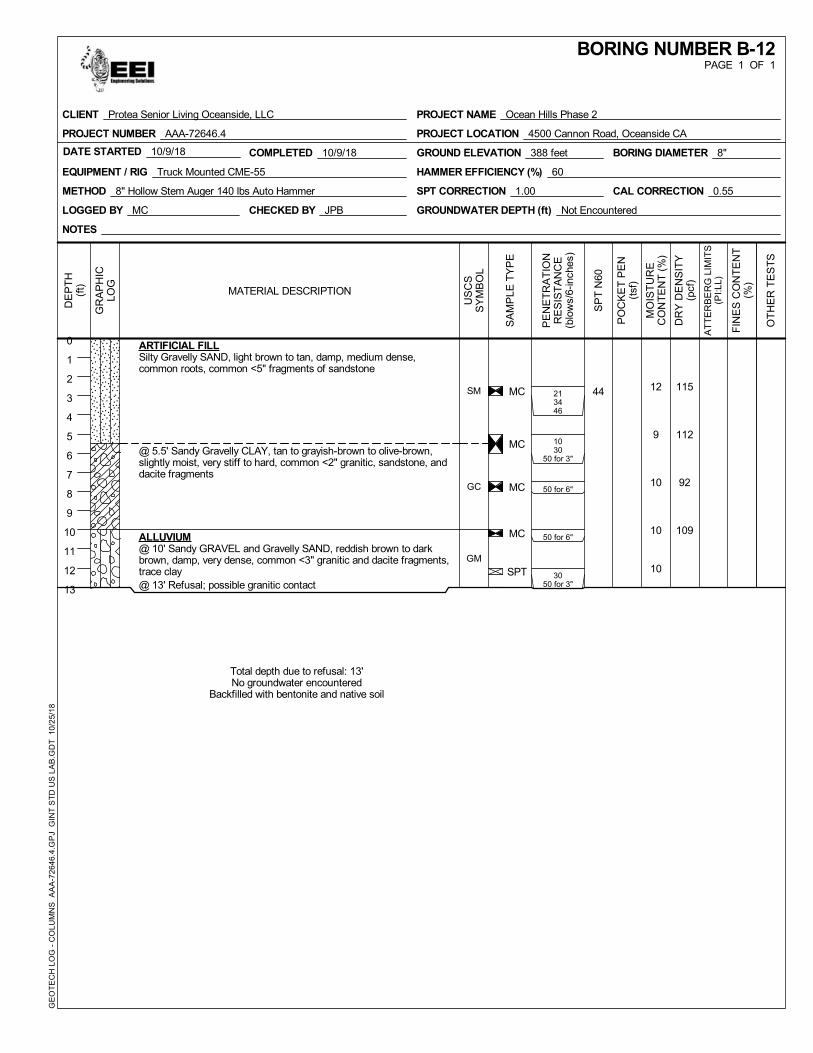
MC
MC
MC
MC
SPT
12
9
10
10
10
115
112
92
109
213446
1030
50 for 3"
50 for 6"
50 for 6"
3050 for 3"
44SM
GC
GM
ARTIFICIAL FILLSilty Gravelly SAND, light brown to tan, damp, medium dense,common roots, common <5" fragments of sandstone
@ 5.5' Sandy Gravelly CLAY, tan to grayish-brown to olive-brown,slightly moist, very stiff to hard, common <2" granitic, sandstone, anddacite fragments
ALLUVIUM@ 10' Sandy GRAVEL and Gravelly SAND, reddish brown to darkbrown, damp, very dense, common <3" granitic and dacite fragments,trace clay@ 13' Refusal; possible granitic contact
Total depth due to refusal: 13'No groundwater encountered
Backfilled with bentonite and native soil
COMPLETED 10/9/18DATE STARTED 10/9/18
LOGGED BY MC
GROUND ELEVATION 388 feet
EQUIPMENT / RIG Truck Mounted CME-55
METHOD 8" Hollow Stem Auger 140 lbs Auto Hammer
CHECKED BY JPB
HAMMER EFFICIENCY (%) 60
SPT CORRECTION 1.00 CAL CORRECTION 0.55
GROUNDWATER DEPTH (ft) Not Encountered
BORING DIAMETER 8"
NOTES
GR
AP
HIC
LOG
SA
MP
LE T
YP
E
MO
IST
UR
EC
ON
TE
NT
(%
)
DR
Y D
EN
SIT
Y(p
cf)
PE
NE
TR
AT
ION
RE
SIS
TA
NC
E(b
low
s/6-
inch
es)
FIN
ES
CO
NT
EN
T(%
)
DE
PT
H(f
t)
0
1
2
3
4
5
6
7
8
9
10
11
12
13
OT
HE
R T
ES
TS
SP
T N
60
PO
CK
ET
PE
N(t
sf)
US
CS
SY
MB
OL
AT
TE
RB
ER
G L
IMIT
S(P
I:LL)
MATERIAL DESCRIPTION
PAGE 1 OF 1BORING NUMBER B-12
PROJECT NAME Ocean Hills Phase 2
PROJECT LOCATION 4500 Cannon Road, Oceanside CA
CLIENT Protea Senior Living Oceanside, LLC
PROJECT NUMBER AAA-72646.4
GE
OT
EC
H L
OG
- C
OLU
MN
S
AA
A-7
2646
.4.G
PJ
GIN
T S
TD
US
LA
B.G
DT
10/
25/
18
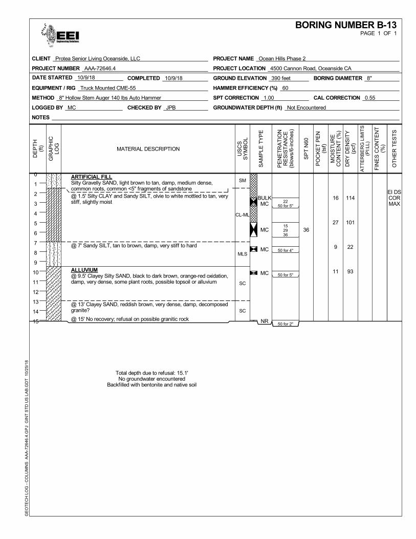
BULKMC
MC
MC
MC
NR
16
27
9
11
114
101
22
93
2250 for 5"
152936
50 for 4"
50 for 5"
50 for 2"
EI DSCORMAX
36
SM
CL-ML
MLS
SC
SC
ARTIFICIAL FILLSilty Gravelly SAND, light brown to tan, damp, medium dense,common roots, common <5" fragments of sandstone@ 1.5' Silty CLAY and Sandy SILT, olvie to white mottled to tan, verystiff, slightly moist
@ 7' Sandy SILT, tan to brown, damp, very stiff to hard
ALLUVIUM@ 9.5' Clayey Silty SAND, black to dark brown, orange-red oxidation,damp, very dense, some plant roots, possible topsoil or alluvium
@ 13' Clayey SAND, reddish brown, very dense, damp, decomposedgranite?
@ 15' No recovery; refusal on possible granitic rock
Total depth due to refusal: 15.1'No groundwater encountered
Backfilled with bentonite and native soil
COMPLETED 10/9/18DATE STARTED 10/9/18
LOGGED BY MC
GROUND ELEVATION 390 feet
EQUIPMENT / RIG Truck Mounted CME-55
METHOD 8" Hollow Stem Auger 140 lbs Auto Hammer
CHECKED BY JPB
HAMMER EFFICIENCY (%) 60
SPT CORRECTION 1.00 CAL CORRECTION 0.55
GROUNDWATER DEPTH (ft) Not Encountered
BORING DIAMETER 8"
NOTES
GR
AP
HIC
LOG
SA
MP
LE T
YP
E
MO
IST
UR
EC
ON
TE
NT
(%
)
DR
Y D
EN
SIT
Y(p
cf)
PE
NE
TR
AT
ION
RE
SIS
TA
NC
E(b
low
s/6-
inch
es)
FIN
ES
CO
NT
EN
T(%
)
DE
PT
H(f
t)
0
1
2
3
4
5
6
7
8
9
10
11
12
13
14
15
OT
HE
R T
ES
TS
SP
T N
60
PO
CK
ET
PE
N(t
sf)
US
CS
SY
MB
OL
AT
TE
RB
ER
G L
IMIT
S(P
I:LL)
MATERIAL DESCRIPTION
PAGE 1 OF 1BORING NUMBER B-13
PROJECT NAME Ocean Hills Phase 2
PROJECT LOCATION 4500 Cannon Road, Oceanside CA
CLIENT Protea Senior Living Oceanside, LLC
PROJECT NUMBER AAA-72646.4
GE
OT
EC
H L
OG
- C
OLU
MN
S
AA
A-7
2646
.4.G
PJ
GIN
T S
TD
US
LA
B.G
DT
10/
25/
18
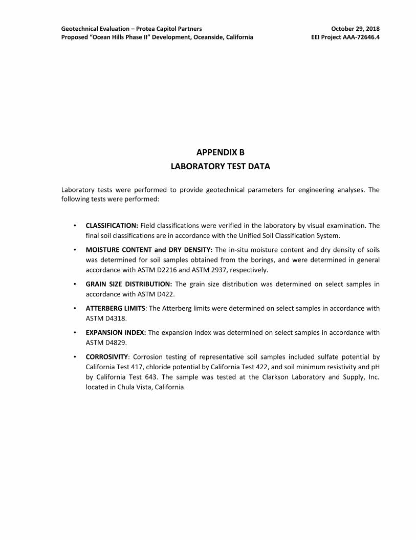
Geotechnical Evaluation – Protea Capitol Partners October 29, 2018 Proposed “Ocean Hills Phase II” Development, Oceanside, California EEI Project AAA-72646.4
APPENDIX B
LABORATORY TEST DATA
Laboratory tests were performed to provide geotechnical parameters for engineering analyses. The following tests were performed:
• CLASSIFICATION: Field classifications were verified in the laboratory by visual examination. The
final soil classifications are in accordance with the Unified Soil Classification System.
• MOISTURE CONTENT and DRY DENSITY: The in-situ moisture content and dry density of soils
was determined for soil samples obtained from the borings, and were determined in general
accordance with ASTM D2216 and ASTM 2937, respectively.
• GRAIN SIZE DISTRIBUTION: The grain size distribution was determined on select samples in
accordance with ASTM D422.
• ATTERBERG LIMITS: The Atterberg limits were determined on select samples in accordance with
ASTM D4318.
• EXPANSION INDEX: The expansion index was determined on select samples in accordance with
ASTM D4829.
• CORROSIVITY: Corrosion testing of representative soil samples included sulfate potential by
California Test 417, chloride potential by California Test 422, and soil minimum resistivity and pH
by California Test 643. The sample was tested at the Clarkson Laboratory and Supply, Inc.
located in Chula Vista, California.
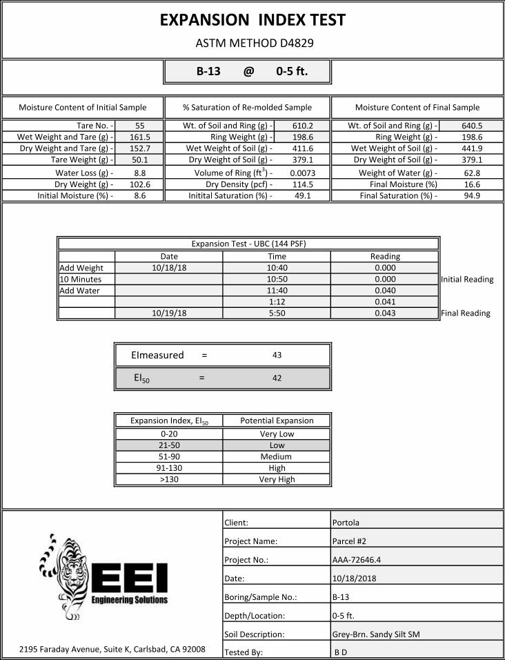
55 610.2 640.5161.5 198.6 198.6152.7 411.6 441.950.1 379.1 379.1
8.8 0.0073 62.8102.6 114.5 16.6
8.6 49.1 94.9
Add Weight10 Minutes Initial ReadingAdd Water
Final Reading
B D
Project Name:
Project No.:
Date:
Boring/Sample No.:
Depth/Location:
AAA-72646.4
10/18/2018
B-13
0-5 ft.
Grey-Brn. Sandy Silt SM
Wet Weight and Tare (g) -
EXPANSION INDEX TEST ASTM METHOD D4829
Water Loss (g) -Dry Weight (g) -
Wt. of Soil and Ring (g) -Ring Weight (g) -
Wet Weight of Soil (g) -
Volume of Ring (ft3) -Dry Density (pcf) -
Dry Weight and Tare (g) -Tare Weight (g) -
Moisture Content of Initial Sample % Saturation of Re-molded Sample Moisture Content of Final Sample
Tare No. -
B-13
Dry Weight of Soil (g) -
Weight of Water (g) -Final Moisture (%)
Final Saturation (%) -
Dry Weight of Soil (g) -
0.00010:5011:40
0.000
Very LowLow
Medium High
Client:
0.0400.041
2195 Faraday Avenue, Suite K, Carlsbad, CA 92008
>130
1:125:50
21-5051-90
Potential Expansion
0.043
Soil Description:
Tested By:
Portola
Parcel #2
10/19/18
Very High
43
42
91-130
0-20
EImeasured =
EI50 =
Expansion Index, EI50
@ 0-5 ft.
Expansion Test - UBC (144 PSF)
10:4010/18/18Date Time Reading
Initial Moisture (%) - Initital Saturation (%) -
Wt. of Soil and Ring (g) -Ring Weight (g) -
Wet Weight of Soil (g) -
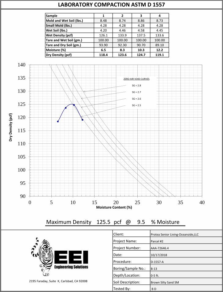
1 2 3 4
8.48 8.74 8.86 8.73
4.28 4.28 4.28 4.28
4.20 4.46 4.58 4.45
126.1 133.9 137.5 133.6
100.00 100.00 100.00 100.00
93.90 92.30 90.70 89.10
6.5 8.3 10.3 12.2
118.4 123.6 124.7 119.1
Maximum Density 125.5 pcf @ 9.5 % Moisture
Project Number:
Sample
Mold and Wet Soil (lbs.)
Small Mold (lbs.)
Wet Soil (lbs.)
LABORATORY COMPACTION ASTM D 1557
Wet Density (pcf)
Moisture (%)
2195 Faraday, Suite K, Carlsbad, CA 92008
Client:
Project Name:
Date:
Procedure:
Boring/Sample No.:
Depth/Location:
Soil Description:
Dry Density (pcf)
Tare and Wet Soil (gm.)
Tare and Dry Soil (gm.)
Tested By:
Protea Senior Living-Oceanside,LLC
Parcel #2
AAA-72646.4
10/17/2018
D-1557-A
B-13
0-5 ft.
Brown Silty Sand SM
B D
90
95
100
105
110
115
120
125
130
135
140
0 5 10 15 20 25 30 35 40
Dry
De
nsi
ty (
pcf
)
Moisture Content (%)
ZERO AIR VOID CURVES
SG = 2.8
SG = 2.7
SG = 2.6
SG = 2.5
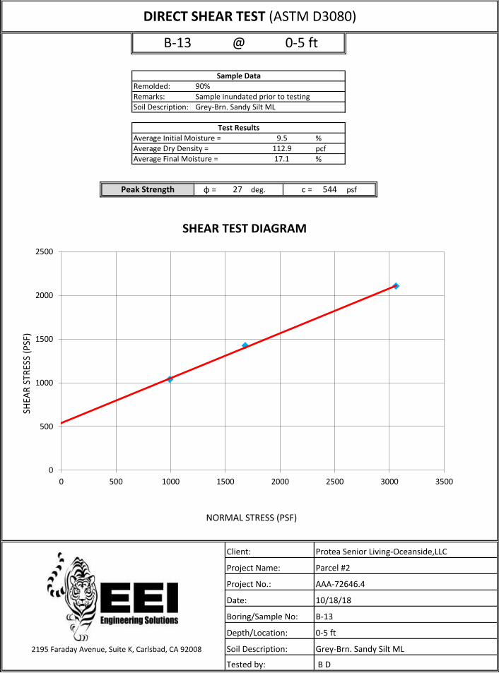
%pcf%
φ = 27 deg. c = 544 psf
2195 Faraday Avenue, Suite K, Carlsbad, CA 92008
17.1
Peak Strength
Average Initial Moisture =Average Dry Density =Average Final Moisture =
9.5112.9
Test Results
Sample Data90%
@B-13 0-5 ft
Soil Description:
Tested by:
Protea Senior Living-Oceanside,LLC
Parcel #2
AAA-72646.4
10/18/18
B-13
0-5 ft
Grey-Brn. Sandy Silt ML
B D
Client:
Project Name:
Project No.:
Date:
Boring/Sample No:
Depth/Location:
Remarks: Sample inundated prior to testingRemolded:
Soil Description: Grey-Brn. Sandy Silt ML
DIRECT SHEAR TEST (ASTM D3080)
0
500
1000
1500
2000
2500
0 500 1000 1500 2000 2500 3000 3500
SHEA
R S
TRES
S (P
SF)
NORMAL STRESS (PSF)
SHEAR TEST DIAGRAM
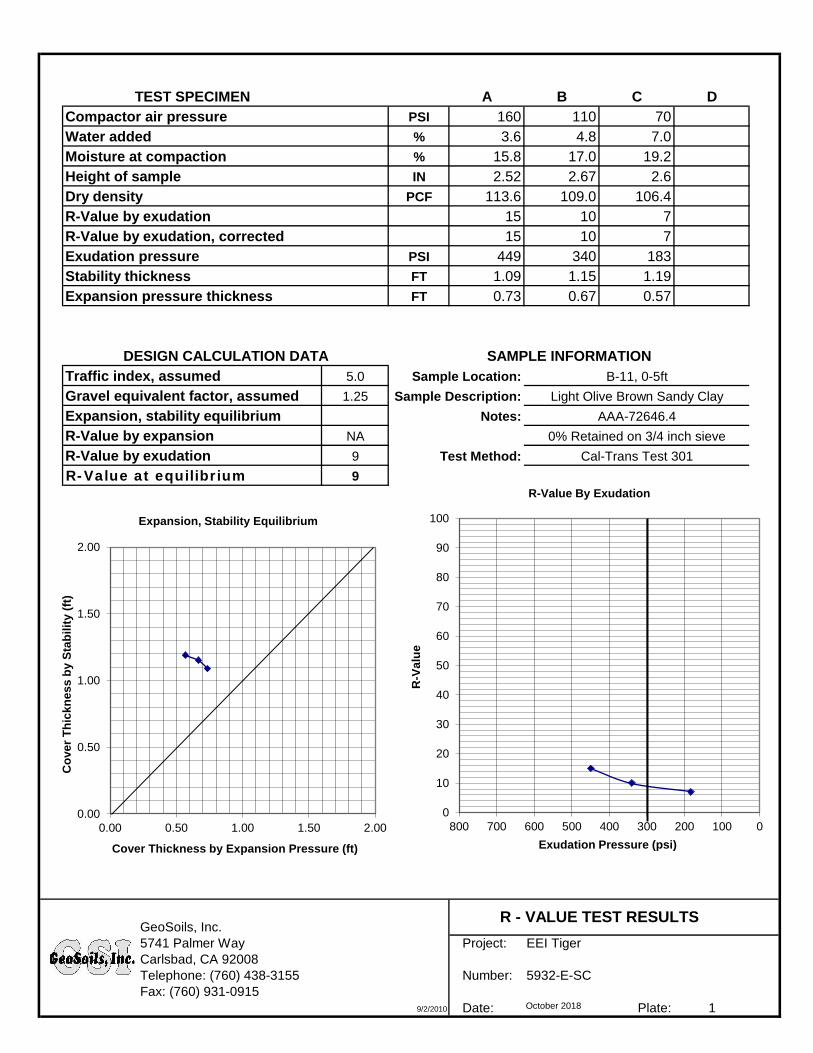
A B C D
Compactor air pressure PSI 160 110 70
Water added % 3.6 4.8 7.0
Moisture at compaction % 15.8 17.0 19.2
Height of sample IN 2.52 2.67 2.6
Dry density PCF 113.6 109.0 106.4
R-Value by exudation 15 10 7
R-Value by exudation, corrected 15 10 7
Exudation pressure PSI 449 340 183
Stability thickness FT 1.09 1.15 1.19
Expansion pressure thickness FT 0.73 0.67 0.57
Traffic index, assumed 5.0 Sample Location:
Gravel equivalent factor, assumed 1.25 Sample Description:
Expansion, stability equilibrium Notes:
R-Value by expansion NA
R-Value by exudation 9 Test Method:
R-Value at equilibrium 9
GeoSoils, Inc.
5741 Palmer Way Project: EEI Tiger
Carlsbad, CA 92008
Telephone: (760) 438-3155 Number: 5932-E-SC
Fax: (760) 931-0915
9/2/2010 Date: October 2018 Plate: 1
TEST SPECIMEN
R - VALUE TEST RESULTS
AAA-72646.4
DESIGN CALCULATION DATA
0% Retained on 3/4 inch sieve
Light Olive Brown Sandy Clay
SAMPLE INFORMATION
B-11, 0-5ft
Cal-Trans Test 301
0.00
0.50
1.00
1.50
2.00
0.00 0.50 1.00 1.50 2.00
Co
ve
r T
hic
kn
es
s b
y S
tab
ilit
y (
ft)
Cover Thickness by Expansion Pressure (ft)
Expansion, Stability Equilibrium
0
10
20
30
40
50
60
70
80
90
100
0100200300400500600700800
R-V
alu
e
Exudation Pressure (psi)
R-Value By Exudation
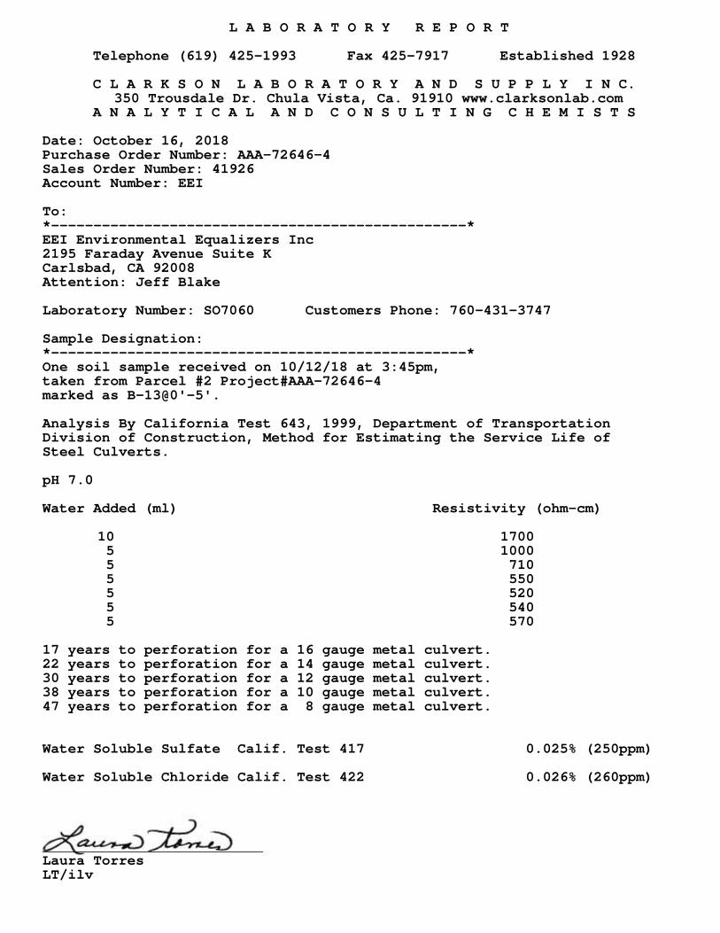
L A B O R A T O R Y R E P O R T
Telephone (619) 425-1993 Fax 425-7917 Established 1928
C L A R K S O N L A B O R A T O R Y A N D S U P P L Y I N C. 350 Trousdale Dr. Chula Vista, Ca. 91910 www.clarksonlab.com
A N A L Y T I C A L A N D C O N S U L T I N G C H E M I S T S
Date: October 16, 2018 Purchase Order Number: AAA-72646-4 Sales Order Number: 41926Account Number: EEI
To: *-------------------------------------------------* EEI Environmental Equalizers Inc2195 Faraday Avenue Suite KCarlsbad, CA 92008Attention: Jeff Blake
Laboratory Number: SO7060 Customers Phone: 760-431-3747
Sample Designation: *-------------------------------------------------* One soil sample received on 10/12/18 at 3:45pm, taken from Parcel #2 Project#AAA-72646-4marked as B-13@0'-5'. Analysis By California Test 643, 1999, Department of TransportationDivision of Construction, Method for Estimating the Service Life ofSteel Culverts. pH 7.0
Water Added (ml) Resistivity (ohm-cm)
10 17005 10005 7105 5505 5205 5405 570
17 years to perforation for a 16 gauge metal culvert.22 years to perforation for a 14 gauge metal culvert.30 years to perforation for a 12 gauge metal culvert.38 years to perforation for a 10 gauge metal culvert.47 years to perforation for a 8 gauge metal culvert.
Water Soluble Sulfate Calif. Test 417 0.025% (250ppm)
Water Soluble Chloride Calif. Test 422 0.026% (260ppm)
__________________________Laura TorresLT/ilv

Geotechnical Evaluation – Protea Capitol Partners October 29, 2018 Proposed “Ocean Hills Phase II” Development, Oceanside, California EEI Project AAA-72646.4
APPENDIX C
FORM I 8
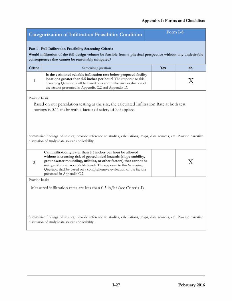
Appendix I: Forms and Checklists
I-27 February 2016
Categorization of Infiltration Feasibility ConditionForm I-8
Part 1 - Full Infiltration Feasibility Screening Criteria
Would infiltration of the full design volume be feasible from a physical perspective without any undesirable
consequences that cannot be reasonably mitigated?
Criteria Screening Question Yes No
1
Is the estimated reliable infiltration rate below proposed facility locations greater than 0.5 inches per hour? The response to this Screening Question shall be based on a comprehensive evaluation of the factors presented in Appendix C.2 and Appendix D.
Provide basis:
Summarize findings of studies; provide reference to studies, calculations, maps, data sources, etc. Provide narrative
discussion of study/data source applicability.
2
Can infiltration greater than 0.5 inches per hour be allowed without increasing risk of geotechnical hazards (slope stability, groundwater mounding, utilities, or other factors) that cannot be mitigated to an acceptable level? The response to this Screening Question shall be based on a comprehensive evaluation of the factors presented in Appendix C.2.
Provide basis:
Summarize findings of studies; provide reference to studies, calculations, maps, data sources, etc. Provide narrative
discussion of study/data source applicability.
X
X
Based on our percolation testing at the site, the calculated Infiltration Rate at both test borings is 0.11 in/hr with a factor of safety of 2.0 applied.
Measured infiltration rates are less than 0.5 in/hr (see Criteria 1).
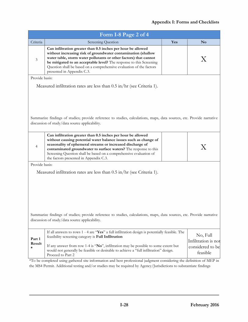
Appendix I: Forms and Checklists
I-28 February 2016
Form I-8 Page 2 of 4
Criteria Screening Question Yes No
3
Can infiltration greater than 0.5 inches per hour be allowed without increasing risk of groundwater contamination (shallow water table, storm water pollutants or other factors) that cannot be mitigated to an acceptable level? The response to this Screening Question shall be based on a comprehensive evaluation of the factors presented in Appendix C.3.
Provide basis:
Summarize findings of studies; provide reference to studies, calculations, maps, data sources, etc. Provide narrative
discussion of study/data source applicability.
4
Can infiltration greater than 0.5 inches per hour be allowed without causing potential water balance issues such as change of seasonality of ephemeral streams or increased discharge of contaminated groundwater to surface waters? The response to this Screening Question shall be based on a comprehensive evaluation of the factors presented in Appendix C.3.
Provide basis:
Summarize findings of studies; provide reference to studies, calculations, maps, data sources, etc. Provide narrative
discussion of study/data source applicability.
Part 1 Result*
If all answers to rows 1 - 4 are “Yes” a full infiltration design is potentially feasible. The feasibility screening category is Full Infiltration
If any answer from row 1-4 is “No”, infiltration may be possible to some extent but would not generally be feasible or desirable to achieve a “full infiltration” design. Proceed to Part 2
*To be completed using gathered site information and best professional judgment considering the definition of MEP in
the MS4 Permit. Additional testing and/or studies may be required by Agency/Jurisdictions to substantiate findings
X
X
Measured infiltration rates are less than 0.5 in/hr (see Criteria 1).
Measured infiltration rates are less than 0.5 in/hr (see Criteria 1).
No, Full Infiltration is not considered to be
feasible
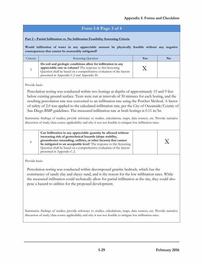
Appendix I: Forms and Checklists
I-29 February 2016
Form I-8 Page 3 of 4
Part 2 – Partial Infiltration vs. No Infiltration Feasibility Screening Criteria
Would infiltration of water in any appreciable amount be physically feasible without any negative
consequences that cannot be reasonably mitigated?
Criteria Screening Question Yes No
5
Do soil and geologic conditions allow for infiltration in any appreciable rate or volume? The response to this Screening Question shall be based on a comprehensive evaluation of the factors presented in Appendix C.2 and Appendix D.
Provide basis:
Summarize findings of studies; provide reference to studies, calculations, maps, data sources, etc. Provide narrative
discussion of study/data source applicability and why it was not feasible to mitigate low infiltration rates.
6
Can Infiltration in any appreciable quantity be allowed without increasing risk of geotechnical hazards (slope stability, groundwater mounding, utilities, or other factors) that cannot be mitigated to an acceptable level? The response to this Screening Question shall be based on a comprehensive evaluation of the factors presented in Appendix C.2.
Provide basis:
Summarize findings of studies; provide reference to studies, calculations, maps, data sources, etc. Provide narrative
discussion of study/data source applicability and why it was not feasible to mitigate low infiltration rates.
X
X
Percolation testing was conducted within two borings at depths of approximately 15 and 9 feetbelow existing ground surface. Tests were run at intervals of 30 minutes for each boring, and the resulting percolation rate was converted to an infiltration rate using the Porchet Method. A factor of safety of 2.0 was applied to the calculated infiltration rate, per the City of Oceanside/County ofSan Diego BMP guidelines. The measured infiltration rate at both borings is 0.11 in/hr.
Percolation testing was conducted within decomposed granitic bedrock, which has the consistency of sandy clay and clayey sand, and is the reason for the low infiltration rates. While the measured infiltration could technically allow for partial infiltration at the site, they could also pose a hazard to utilities for the proposed development.
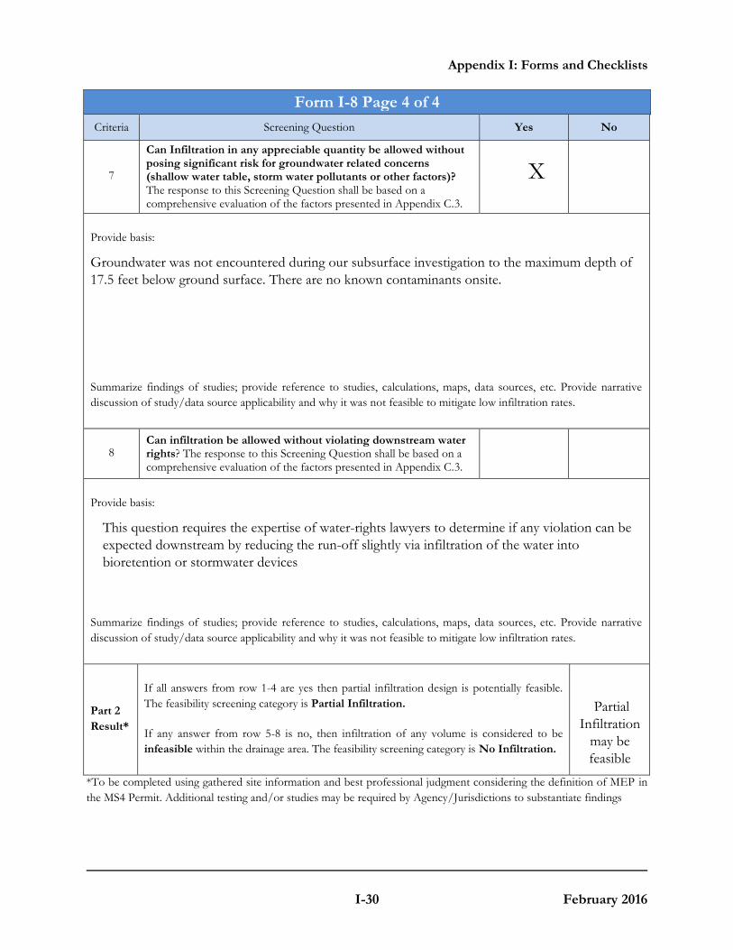
Appendix I: Forms and Checklists
I-30 February 2016
Form I-8 Page 4 of 4
Criteria Screening Question Yes No
7
Can Infiltration in any appreciable quantity be allowed without posing significant risk for groundwater related concerns (shallow water table, storm water pollutants or other factors)? The response to this Screening Question shall be based on a comprehensive evaluation of the factors presented in Appendix C.3.
Summarize findings of studies; provide reference to studies, calculations, maps, data sources, etc. Provide narrative
discussion of study/data source applicability and why it was not feasible to mitigate low infiltration rates.
8 Can infiltration be allowed without violating downstream water rights? The response to this Screening Question shall be based on a comprehensive evaluation of the factors presented in Appendix C.3.
Provide basis:
Summarize findings of studies; provide reference to studies, calculations, maps, data sources, etc. Provide narrative
discussion of study/data source applicability and why it was not feasible to mitigate low infiltration rates.
Part 2
Result*
If all answers from row 1-4 are yes then partial infiltration design is potentially feasible.
The feasibility screening category is Partial Infiltration.
If any answer from row 5-8 is no, then infiltration of any volume is considered to be
infeasible within the drainage area. The feasibility screening category is No Infiltration.
*To be completed using gathered site information and best professional judgment considering the definition of MEP in
the MS4 Permit. Additional testing and/or studies may be required by Agency/Jurisdictions to substantiate findings
X
Provide basis:
Groundwater was not encountered during our subsurface investigation to the maximum depth of 17.5 feet below ground surface. There are no known contaminants onsite.
This question requires the expertise of water-rights lawyers to determine if any violation can beexpected downstream by reducing the run-off slightly via infiltration of the water into bioretention or stormwater devices
Partial Infiltration
may befeasible
Geotechnical Evaluation – Protea Capitol Partners October 29, 2018 Proposed “Ocean Hills Phase II” Development, Oceanside, California EEI Project AAA-72646.4
APPENDIX D
EARTHWORK AND GRADING GUIDELINES
EARTHWORK AND GRADING GUIDELINES
GENERAL
These guidelines present general procedures and recommendations for earthwork and grading as required on the approved grading plans, including preparation of areas to be filled, placement of fill and installation of subdrains and excavations. The recommendations contained in the geotechnical report are applicable to each specific project, are part of the earthwork and grading guidelines and would supersede the provisions contained hereafter in the case of conflict. Observations and/or testing performed by the consultant during the course of grading may result in revised recommendations which could supersede these guidelines or the recommendations contained in the geotechnical report. Figures A through O is provided at the back of this appendix, exhibiting generalized cross sections relating to these guidelines. The contractor is responsible for the satisfactory completion of all earthworks in accordance with provisions of the project plans and specifications. The project soil engineer and engineering geologist (geotechnical consultant) or their representatives should provide observation and testing services, and geotechnical consultation throughout the duration of the project. EARTHWORK OBSERVATIONS AND TESTING
Geotechnical Consultant
Prior to the commencement of grading, a qualified geotechnical consultant (a soil engineer and engineering geologist) should be employed for the purpose of observing earthwork procedures and testing the fills for conformance with the recommendations of the geotechnical report, the approved grading plans, and applicable grading codes and ordinances. The geotechnical consultant should provide testing and observation so that determination may be made that the work is being completed as specified. It is the responsibility of the contractor to assist the consultant and keep them aware of work schedules and predicted changes, so that the consultant may schedule their personnel accordingly. All removals, prepared ground to receive fill, key excavations, and subdrains should be observed and documented by the project engineering geologist and/or soil engineer prior to placing any fill. It is the contractor’s responsibility to notify the engineering geologist and soil engineer when such areas are ready for observation.
Corporate Office: 2195 Faraday Ave., Suite K, Carlsbad, CA 92008-7207 Ph: 760-431-3747 www.eeitiger.com
Camarillo * Carlsbad * Pleasanton * Sacramento * Reno
Earthwork and Grading Guidelines
2
Laboratory and Field Tests
Maximum dry density tests to determine the degree of compaction should be performed in accordance with American Standard Testing Materials test method ASTM designation D-1557-78. Random field compaction tests should be performed in accordance with test method ASTM designations D-1556-82, D-2937 or D-2922 & D-3017, at intervals of approximately two feet of fill height per 10,000 sq. ft. or every one thousand cubic yards of fill placed. These criteria would vary depending on the soil conditions and the size of the project. The location and frequency of testing would be at the discretion of the geotechnical consultant
Contractor’s Responsibility
All clearing, site preparation, and earthwork performed on the project should be conducted by the contractor, with observation by geotechnical consultants and staged approval by the appropriate governing agencies. It is the contractor’s responsibility to prepare the ground surface to receive the fill to the satisfaction of the soil engineer, and to place, spread, moisture condition, mix and compact the fill in accordance with the recommendations of the soil engineer. The contractor should also remove all major deleterious material considered unsatisfactory by the soil engineer.
It is the sole responsibility of the contractor to provide adequate equipment and methods to accomplish the earthwork in accordance with applicable grading guidelines, codes or agency ordinances, and approved grading plans. Sufficient watering apparatus and compaction equipment should be provided by the contractor with due consideration for the fill material, rate of placement, and climatic conditions. If, in the opinion of the geotechnical consultant, unsatisfactory conditions such as questionable weather, excessive oversized rock, deleterious material or insufficient support equipment are resulting in a quality of work that is not acceptable, the consultant will inform the contractor, and the contractor is expected to rectify the conditions, and if necessary, stop work until conditions are satisfactory.
The contractor will properly grade all surfaces to maintain good drainage and prevent ponding of water. The contractor will take action to control surface water and to prevent erosion control measures that have been installed.
SITE PREPARATION
All vegetation including brush, trees, thick grasses, organic debris, and other deleterious material should be removed and disposed of offsite, and must be concluded prior to placing fill. Existing fill, soil, alluvium, colluvium, or rock materials determined by the soil engineer or engineering geologist as unsuitable for structural in-place support should be removed prior to fill placement. Depending upon the soil conditions, these materials may be reused as compacted fills. Any materials incorporated as part of the compacted fills should be approved by the soil engineer.
Any underground structures such as cesspools, cisterns, mining shafts, tunnels, septic tanks, wells, pipelines, or other structures not located prior to grading are to be removed or treated in a manner recommended by the soil engineer. Soft, dry, spongy, highly fractured, or otherwise unsuitable ground extending to such a depth that surface processing cannot adequately improve the condition should be over excavated down to firm ground and approved by the soil engineer before compaction and filling operations continue. Over excavated and processed soils which have been properly mixed and moisture-conditioned should be recompacted to the minimum relative compaction as specified in these guidelines.
Earthwork and Grading Guidelines
3
Existing ground which is determined to be satisfactory for support of the fills should be scarified to a minimum depth of 6 inches, or as directed by the soil engineer. After the scarified ground is brought to optimum moisture (or greater) and mixed, the materials should be compacted as specified herein. If the scarified zone is greater than 6 inches in depth, it may be necessary to remove the excess and place the material in lifts restricted to 6 inches in compacted thickness.
Existing grind which is not satisfactory to support compacted fill should be over excavated as required in the geotechnical report or by the onsite soils engineer and/or engineering geologists. Scarification, discing, or other acceptable form of mixing should continue until the soils are broken down and free of large fragments or clods, until the working surface is reasonably uniform and free from ruts, hollows, hummocks, or other uneven features which would inhibit compaction as described above.
Where fills are to be placed on ground with slopes steeper than 5:1 (horizontal to vertical) gradient, the ground should be benched. The lowest bench, which will act as a key, should be a minimum of 12 feet wide and should be at least two feet deep into competent material, approved by the soil engineer and/or engineering geologist. In fill over cut slope conditions, the recommended minimum width of the lowest bench or key is at least 15 feet with the key excavated on competent material, as designated by the Geotechnical Consultant. As a general rule, unless superseded by the Soil Engineer, the minimum width of fill keys should be approximately equal to one-half (½) the height of the slope.
Standard benching is typically four feet (minimum) vertically, exposing competent material. Benching may be used to remove unsuitable materials, although it is understood that the vertical height of the bench may exceed four feet. Pre stripping may be considered for removal of unsuitable materials in excess of four feet in thickness.
All areas to receive fill, including processed areas, removal areas, and toe of fill benches should be observed and approved by the soil engineer and/or engineering geologist prior to placement of fill. Fills may then be properly placed and compacted until design grades are attained.
COMPACTED FILLS
Earth materials imported or excavated on the property may be utilized as fill provided that each soil type has been accepted by the soil engineer. These materials should be free of roots, tree branches, other organic matter or other deleterious materials. All unsuitable materials should be removed from the fill as directed by the soil engineer. Soils of poor gradation, undesirable expansion potential, or substandard strength characteristics may be designated unsuitable by the consultant and may require mixing with other earth materials to serve as a satisfactory fill material.
Fill materials generated from benching operations should be dispersed throughout the fill area. Benching operations should not result in the benched material being placed only within a single equipment width away from the fill/bedrock contact.
Earthwork and Grading Guidelines
4
Oversized materials, defined as rock or other irreducible materials with a maximum size exceeding 12 inches in one dimension, should not be buried or placed in fills unless the location of materials and disposal methods are specifically approved by the soil engineer. Oversized material should be taken offsite or placed in accordance with recommendations of the soil engineer in areas designated as suitable for rock disposal. Oversized material should not be placed vertically within 10 feet of finish grade or horizontally within 20 feet of slope faces.
To facilitate trenching, rock should not be placed within the range of foundation excavations or future utilities unless specifically approved by the soil engineer and/or the representative developers.
If import fill material is required for grading, representative samples of the material should be analyzed in the laboratory by the soil engineer to determine its physical properties. If any material other than that previously analyzed is imported to the fill or encountered during grading, analysis of this material should be conducted by the soil engineer as soon as practical.
Fill material should be placed in areas prepared to receive fill in near-horizontal layers that should not exceed six inches compacted in thickness. The soil engineer may approve thicker lifts if testing indicates the grading procedures are such that adequate compaction is being achieved. Each layer should be spread evenly and mixed to attain uniformity of material and moisture suitable for compaction.
Fill materials at moisture content less than optimum should be watered and mixed, and “wet” fill materials should be aerated by scarification, or should be mixed with drier material. Moisture conditioning and mixing of fill materials should continue until the fill materials have uniform moisture content at or above optimum moisture.
After each layer has been evenly spread, moisture-conditioned and mixed, it should be uniformly compacted to a minimum of 90 percent of maximum density as determined by ASTM test designation, D 1557-78, or as otherwise recommended by the soil engineer. Compaction equipment should be adequately sized and should be reliable to efficiently achieve the required degree of compaction.
Where tests indicate that the density of any layer of fill, or portion thereof, is below the required relative compaction or improper moisture content, the particular layer or portion will be reworked until the required density and/or moisture content has been attained. No additional fill will be placed in an area until the last placed lift of fill has been tested and found to meet the density and moisture requirements, and is approved by the soil engineer.
Compaction of slopes should be accomplished by over-building the outside edge a minimum of three feet horizontally, and subsequently trimming back to the finish design slope configuration. Testing will be performed as the fill is horizontally placed to evaluate compaction as the fill core is being developed. Special efforts may be necessary to attain the specified compaction in the fill slope zone. Final slope shaping should be performed by trimming and removing loose materials with appropriate equipment. A final determination of fill slope compaction should be based on observation and/or testing of the finished slope face.
Earthwork and Grading Guidelines
5
If an alternative to over-building and cutting back the compacted fill slope is selected, then additional efforts should be made to achieve the required compaction in the outer 10 feet of each lift of fill by undertaking the following:
• Equipment consisting of a heavy short-shanked sheepsfoot should be used to roll
(horizontal) parallel to the slopes continuously as fill is placed. The sheepsfoot roller should also be used to roll perpendicular to the slopes, and extend out over the slope to provide adequate compaction to the face slope.
• Loose fill should not be spilled out over the face of the slope as each lift is compacted.
Any loose fill spilled over a previously completed slope face should be trimmed off or be subject to re-rolling.
• Field compaction tests will be made in the outer two to five feet of the slope at two
to three foot vertical intervals, subsequent to compaction operations.
• After completion of the slope, the slope face should be shaped with a small dozer and then re-rolled with a sheepsfoot to achieve compaction to near the slope face. Subsequent to testing to verify compaction, the slopes should be grid-rolled to achieve adequate compaction to the slope face. Final testing should be used to confirm compaction after grid rolling.
• Where testing indicates less than adequate compaction, the contractor will be
responsible to process, moisture condition, mix and recompact the slope materials as necessary to achieve compaction. Additional testing should be performed to verify compaction.
• Erosion control and drainage devices should be designed by the project civil engineer in
compliance with the ordinances of the controlling governmental agencies, and/or in accordance with the recommendations of the soil engineer or engineering geologist.
EXCAVATIONS
Excavations and cut slopes should be observed and mapped during grading by the engineering geologist. If directed by the engineering geologist, further excavations or over-excavation and refilling of cut areas should be performed. When fills over cut slopes are to be graded, the cut portion of the slope should be observed by the engineering geologist prior to placement of the overlying fill portion of the slope. The engineering geologist should observe all cut slopes and should be notified by the contractor when cut slopes are started.
If, during the course of grading, unanticipated adverse or potentially adverse geologic conditions are encountered, the engineering geologist and soil engineer should investigate, evaluate and make recommendations to mitigate (or limit) these conditions. The need for cut slope buttressing or stabilizing should be based on as-grading evaluations by the engineering geologist, whether anticipated previously or not.
Unless otherwise specified in soil and geological reports, no cut slopes should be excavated higher or steeper than that allowed by the ordinances of controlling governmental agencies. Additionally, short-term stability of temporary cut slopes is the contractor’s responsibility.
Earthwork and Grading Guidelines
6
Erosion control and drainage devices should be designed by the project civil engineer and should be constructed in compliance with the ordinances of the controlling governmental agencies, and/or in accordance with the recommendations of the soil engineer or engineering geologist.
SUBDRAIN INSTALLATION
Subdrains should be installed in accordance with the approved embedment material, alignment and details indicated by the geotechnical consultant. Subdrain locations or construction materials should not be changed or modified without approval of the geotechnical consultant. The soil engineer and/or engineering geologist may recommend and direct changes in subdrain line, grade and drain material in the field, pending exposed conditions. The location of constructed subdrains should be recorded by the project civil engineer.
COMPLETION
Consultation, observation and testing by the geotechnical consultant should be completed during grading operations in order to state an opinion that all cut and filled areas are graded in accordance with the approved project specifications.
After completion of grading and after the soil engineer and engineering geologist have finished their observations, final reports should be submitted subject to review by the controlling governmental agencies. No additional grading should be undertaken without prior notification of the soil engineer and/or engineering geologist.
All finished cut and fill slopes should be protected from erosion, including but not limited to planting in accordance with the plan design specifications and/or as recommended by a landscape architect. Such protection and/or planning should be undertaken as soon as possible after completion of grading.
ATTACHMENTS
Figure A – Transition Lot Detail Cut Lot Figure B – Transition Lot Detail Cut - Fill Figure C – Rock Disposal Pits Figure D – Detail for Fill Slope Toeing out on a Flat Alluviated Canyon Figure E – Removal Adjacent to Existing Fill Figure F – Daylight Cut Lot Detail Figure G – Skin Fill of Natural Ground Figure H – Typical Stabilization Buttress Fill Design Figure I – Stabilization Fill for Unstable Material Exposed in Portion of Cut Slope Figure J – Fill Over Cut Detail Figure K – Fill Over Natural Detail Figure L – Oversize Rock Disposal Figure M – Canyon Subdrain Detail Figure N – Canyon Subdrain Alternate Details Figure O – Typical Stabilization Buttress Subdrain Detail Figure P – Retaining Wall Backfill
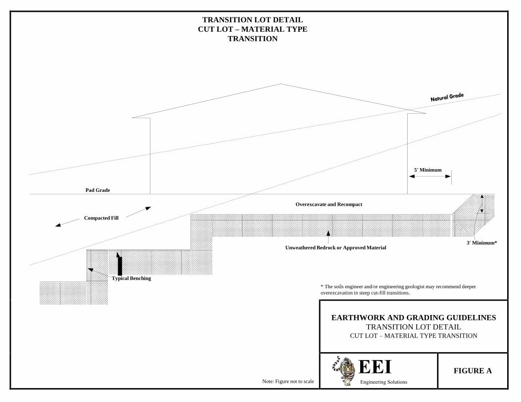
TRANSITION LOT DETAIL
CUT LOT – MATERIAL TYPE
TRANSITION
5' Minimum
Pad Grade
Overexcavate and Recompact
Compacted Fill
3' Minimum* Unweathered Bedrock or Approved Material
Typical Benching
* The soils engineer and/or engineering geologist may recommend deeper overexcavation in steep cut-fill transitions.
Note: Figure not to scale
EARTHWORK AND GRADING GUIDELINES TRANSITION LOT DETAIL
CUT LOT – MATERIAL TYPE TRANSITION
FIGURE A Engineering Solutions
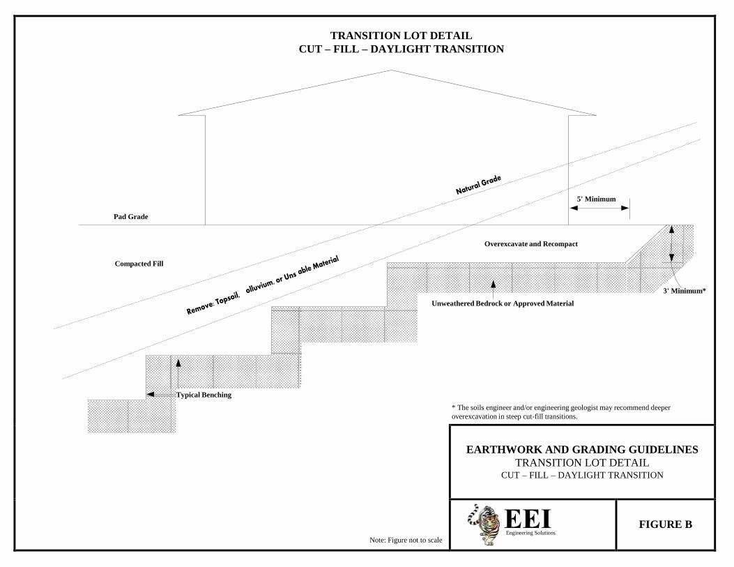
TRANSITION LOT DETAIL
CUT – FILL – DAYLIGHT TRANSITION
5' Minimum
Pad Grade
Overexcavate and Recompact
Compacted Fill
3' Minimum*
Unweathered Bedrock or Approved Material
Typical Benching
* The soils engineer and/or engineering geologist may recommend deeper overexcavation in steep cut-fill transitions.
Note: Figure not to scale
EARTHWORK AND GRADING GUIDELINES TRANSITION LOT DETAIL
CUT – FILL – DAYLIGHT TRANSITION
Engineering Solutions
FIGURE B
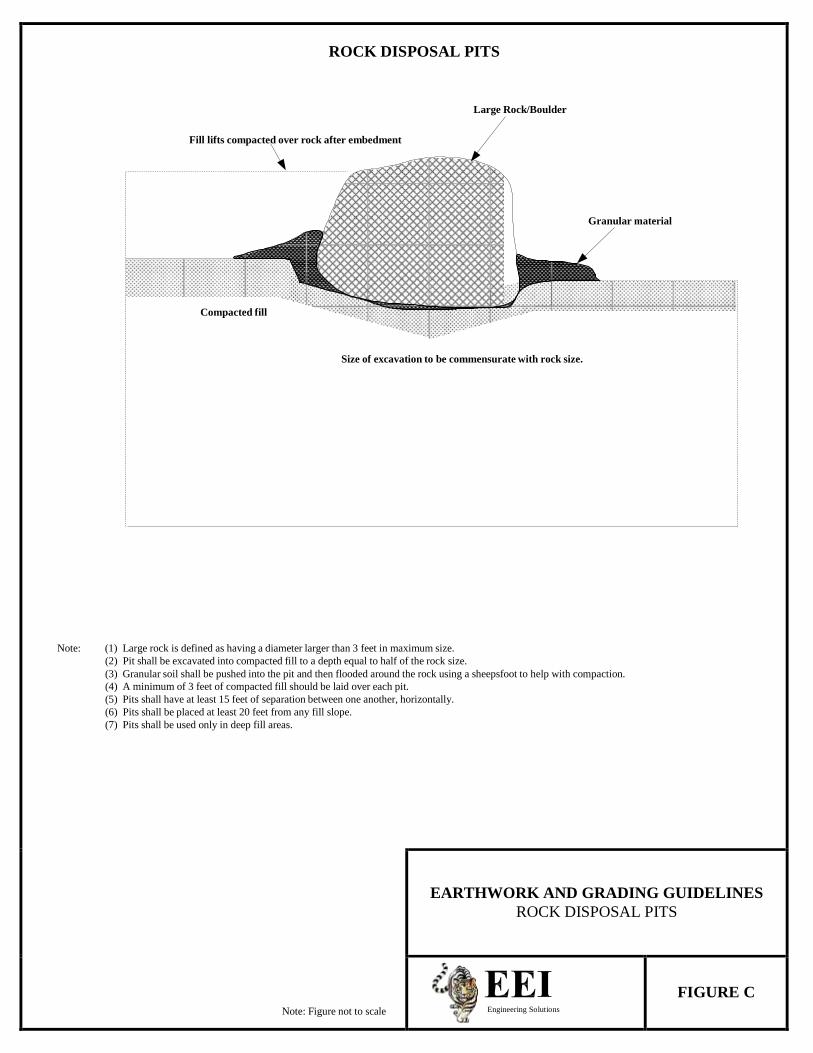
ROCK DISPOSAL PITS
Large Rock/Boulder
Fill lifts compacted over rock after embedment
Granular material
Compacted fill
Size of excavation to be commensurate with rock size.
Note: (1) Large rock is defined as having a diameter larger than 3 feet in maximum size. (2) Pit shall be excavated into compacted fill to a depth equal to half of the rock size. (3) Granular soil shall be pushed into the pit and then flooded around the rock using a sheepsfoot to help with compaction. (4) A minimum of 3 feet of compacted fill should be laid over each pit. (5) Pits shall have at least 15 feet of separation between one another, horizontally. (6) Pits shall be placed at least 20 feet from any fill slope. (7) Pits shall be used only in deep fill areas.
Note: Figure not to scale
EARTHWORK AND GRADING GUIDELINES
ROCK DISPOSAL PITS
Engineering Solutions
FIGURE C
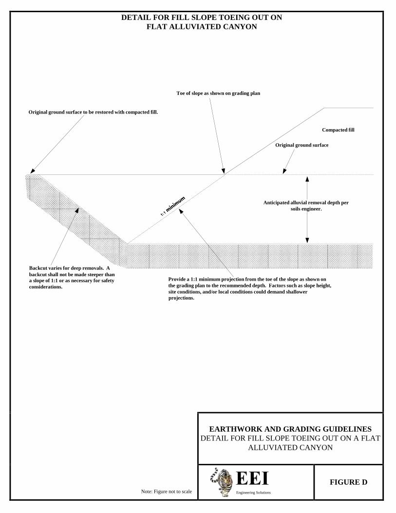
DETAIL FOR FILL SLOPE TOEING OUT ON
FLAT ALLUVIATED CANYON
Toe of slope as shown on grading plan
Original ground surface to be restored with compacted fill.
Compacted fill
Original ground surface
Anticipated alluvial removal depth per
soils engineer.
Backcut varies for deep removals. A backcut shall not be made steeper than a slope of 1:1 or as necessary for safety Provide a 1:1 minimum projection from the toe of the slope as shown on considerations. the grading plan to the recommended depth. Factors such as slope height,
site conditions, and/or local conditions could demand shallower projections.
Note: Figure not to scale
EARTHWORK AND GRADING GUIDELINES
DETAIL FOR FILL SLOPE TOEING OUT ON A FLAT ALLUVIATED CANYON
Engineering Solutions
FIGURE D
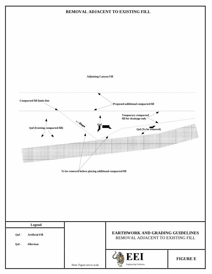
REMOVAL ADJACENT TO EXISTING FILL
Adjoining Canyon Fill
Compacted fill limits line Proposed additional compacted fill
Temporary compacted
fill for drainage only
Qaf Qaf (Existing compacted fill)
Qal (To be removed)
To be removed before placing additional compacted fill
Legend
Note: Figure not to scale
EARTHWORK AND GRADING GUIDELINES
REMOVAL ADJACENT TO EXISTING FILL
Qaf - Artificial Fill
Qal - Alluvium
Engineering Solutions
FIGURE E

DAYLIGHT CUT LOT DETAIL
Fill slope shall be recompacted at a 2:1 ratio (this may increase or
decrease the area of the pad)
Overexcavate and recompact fill
Proposed finish grade
3' minimum blanket fill
Avoid and/or clean up spillage of materials on the natural slope
Bedrock or approved material
Typical benching
2' minimum key depth
Note: (1) Subdrain and key width requirements shall be determined based on exposed subsurface conditions and the thickness of
overburden. (2) Pad overexcavation and recompaction shall be completed if determined as necessary by the soils engineer and/or
engineering geologist.
Note: Figure not to scale
EARTHWORK AND GRADING GUIDELINES
DAYLIGHT CUT LOT DETAIL
Engineering Solutions
FIGURE F

SKIN FILL OF NATURAL GROUND
15' minimum to be maintained from proposed finish Original slope slope face to backcut
Proposed finish grade
3' minimum
Bedrock or approved materials
Proposed finish grade
3' minimum key depth 2' minimum key
depth 15' minimum key width
Note: (1) The need and disposition of drains will be determined by the soils engineer and/or engineering geologist based on site
conditions. (2) Pad overexcavation and recompaction shall be completed if determined as necessary by the soils engineer and/or
engineering geologist.
Note: Figure not to scale
EARTHWORK AND GRADING GUIDELINES
SKIN FILL OF NATURAL GROUND
Engineering Solutions
FIGURE G

TYPICAL STABILIZATION BUTTRESS FILL DESIGN
Outlets shall be spaced at 100' maximum intervals, and should extend 12" beyond the face of the slope at the
finish of of rough grading
15' minimum Blanket fill if recommended by the soils engineer and/or
engineering geologist
Design finish slope 10' minimum
25' maximum
Typical benching
15' is typical Buttress or sidehill fill 4" diameter non-perforated outlet pipe and backdrain (see
alternatives)
1'-2' clear
Toe Heel Gravel-fabric drain material
Bedrock
3' minimum key depth
W = H/2 or a minimum of 15'
Note: Figure not to scale
EARTHWORK AND GRADING GUIDELINES
TYPICAL STABILIZATION BUTTRESS FILL DESIGN
Engineering Solutions
FIGURE H
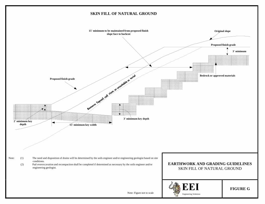
SKIN FILL OF NATURAL GROUND
15' minimum to be maintained from proposed finish Original slope slope face to backcut
Proposed finish grade
3' minimum
Bedrock or approved materials
Proposed finish grade
3' minimum key depth 2' minimum key
depth 15' minimum key width
Note: (1) The need and disposition of drains will be determined by the soils engineer and/or engineering geologist based on site
conditions. (2) Pad overexcavation and recompaction shall be completed if determined as necessary by the soils engineer and/or
engineering geologist.
Note: Figure not to scale
EARTHWORK AND GRADING GUIDELINES
SKIN FILL OF NATURAL GROUND
Engineering Solutions
FIGURE G
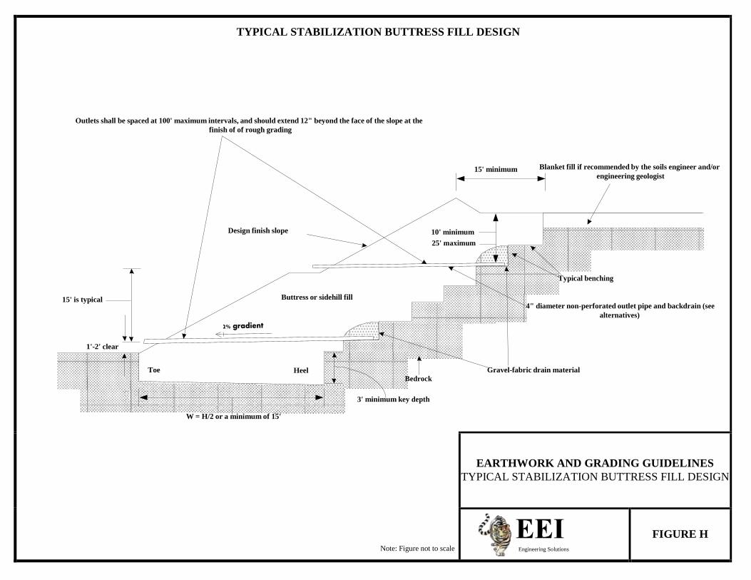
TYPICAL STABILIZATION BUTTRESS FILL DESIGN
Outlets shall be spaced at 100' maximum intervals, and should extend 12" beyond the face of the slope at the
finish of of rough grading
15' minimum Blanket fill if recommended by the soils engineer and/or
engineering geologist
Design finish slope 10' minimum
25' maximum
Typical benching
15' is typical Buttress or sidehill fill 4" diameter non-perforated outlet pipe and backdrain (see
alternatives)
1'-2' clear
Toe Heel Gravel-fabric drain material
Bedrock
3' minimum key depth
W = H/2 or a minimum of 15'
Note: Figure not to scale
EARTHWORK AND GRADING GUIDELINES
TYPICAL STABILIZATION BUTTRESS FILL DESIGN
Engineering Solutions
FIGURE H
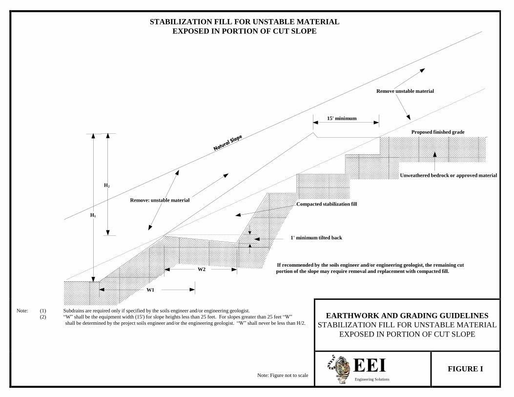
STABILIZATION FILL FOR UNSTABLE MATERIAL
EXPOSED IN PORTION OF CUT SLOPE
Remove unstable material
15' minimum
Proposed finished grade
Unweathered bedrock or approved material
H2
Remove: unstable material
Compacted stabilization fill
H1
1' minimum tilted back
If recommended by the soils engineer and/or engineering geologist, the remaining cut W2 portion of the slope may require removal and replacement with compacted fill.
W1
Note: (1) Subdrains are required only if specified by the soils engineer and/or engineering geologist.
(2) “W” shall be the equipment width (15') for slope heights less than 25 feet. For slopes greater than 25 feet “W” shall be determined by the project soils engineer and/or the engineering geologist. “W” shall never be less than H/2.
Note: Figure not to scale
EARTHWORK AND GRADING GUIDELINES
STABILIZATION FILL FOR UNSTABLE MATERIAL EXPOSED IN PORTION OF CUT SLOPE
Engineering Solutions
FIGURE I
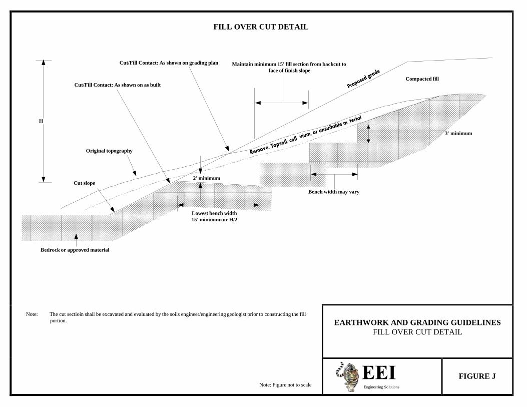
FILL OVER CUT DETAIL
Cut/Fill Contact: As shown on grading plan Maintain minimum 15' fill section from backcut to
face of finish slope
Compacted fill Cut/Fill Contact: As shown on as built
H
3' minimum
Original topography
2' minimum Cut slope
Bench width may vary
Lowest bench width 15' minimum or H/2
Bedrock or approved material
Note: The cut sectioin shall be excavated and evaluated by the soils engineer/engineering geologist prior to constructing the fill
portion.
Note: Figure not to scale
EARTHWORK AND GRADING GUIDELINES FILL OVER CUT DETAIL
Engineering Solutions
FIGURE J
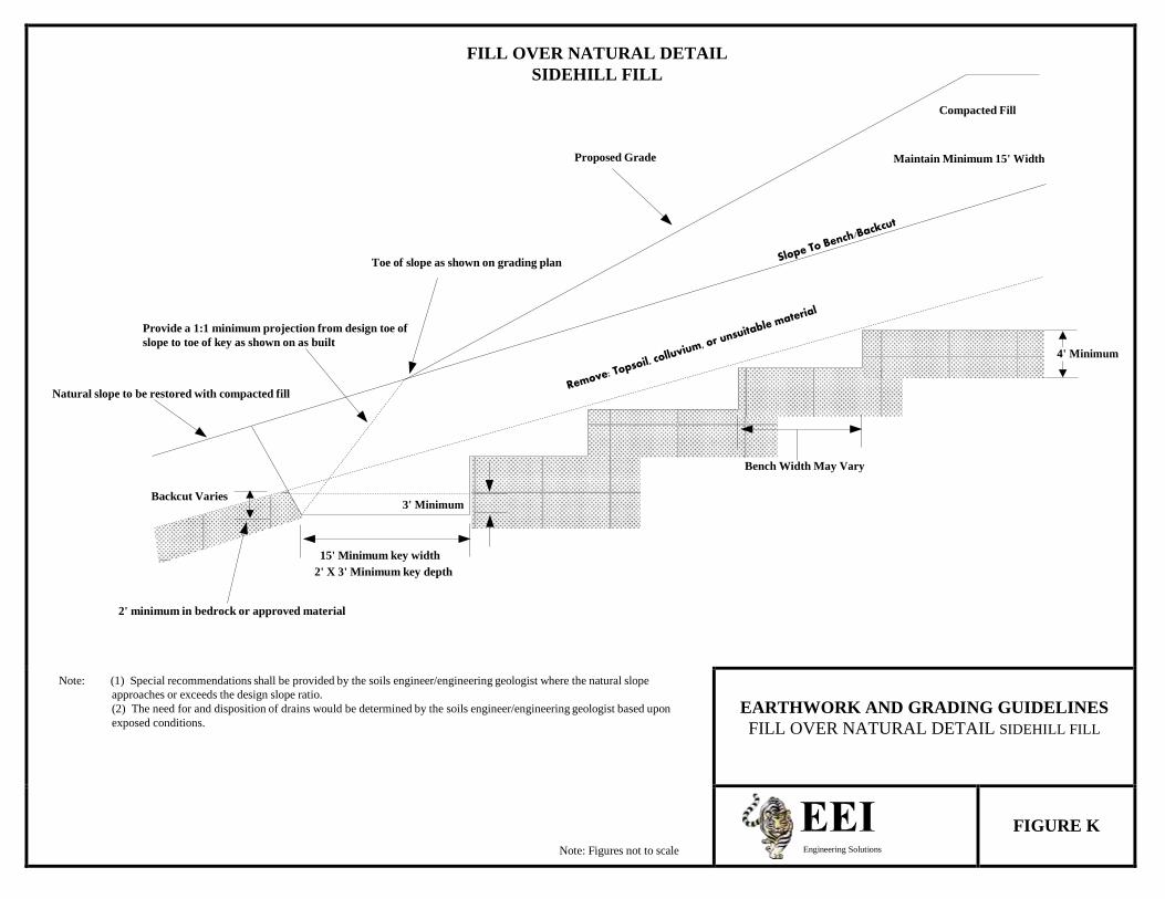
FILL OVER NATURAL DETAIL
SIDEHILL FILL
Compacted Fill
Proposed Grade Maintain Minimum 15' Width
Toe of slope as shown on grading plan
Provide a 1:1 minimum projection from design toe of
slope to toe of key as shown on as built 4' Minimum
Natural slope to be restored with compacted fill
Bench Width May Vary
Backcut Varies 3' Minimum
15' Minimum key width
2' X 3' Minimum key depth
2' minimum in bedrock or approved material
Note: (1) Special recommendations shall be provided by the soils engineer/engineering geologist where the natural slope approaches or exceeds the design slope ratio. (2) The need for and disposition of drains would be determined by the soils engineer/engineering geologist based upon exposed conditions.
Note: Figures not to scale
EARTHWORK AND GRADING GUIDELINES
FILL OVER NATURAL DETAIL SIDEHILL FILL
Engineering Solutions
FIGURE K
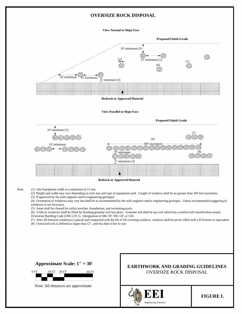
OVERSIZE ROCK DISPOSAL
View Normal to Slope Face
Proposed Finish Grade
10' minimum (5)
(2) 15' minimum (1)
(7) (6)
20' minimum 15' minimum 5' minimum (3)
Bedrock or Approved Material
View Parallel to Slope Face
Proposed Finish Grade
10' minimum (5)
(7)
(4)
10' minimum 100' maximum
3' minimum (8)
5' minimum (3)
Bedrock or Approved Material
Note: (1) One Equipment width or a minimum of 15 feet.
(2) Height and width may vary depending on rock size and type of equipment used. Length of windrow shall be no greater than 100 feet maximum. (3) If approved by the soils engineer and/or engineering geologist. (4) Orientation of windrows may vary but shall be as recommended by the soils engineer and/or engineering geologist. Unless recommended staggering of windrows is not necessary. (5) Areas shall be cleared for utility trenches, foundations, and swimming pools. (6) Voids in windrows shall be filled by flooding granular soil into place. Granular soil shall be any soil which has a unified soil classification system (Universal Building Code (UBC) 29-1). Designation of SM, SP, SW, GP, or GW. (7) After fill between windrows is placed and compacted with the lift of fill covering windrow, windrow shall be proof rolled with a D-9 dozer or equivalent. (8) Oversized rock is defined as larger than 12", and less than 4 feet in size.
Approximate Scale: 1" = 30'
0 FT 18 FT 30 FT 60 FT
Note: All distances are approximate
EARTHWORK AND GRADING GUIDELINES
OVERSIZE ROCK DISPOSAL
Engineering Solutions
FIGURE L
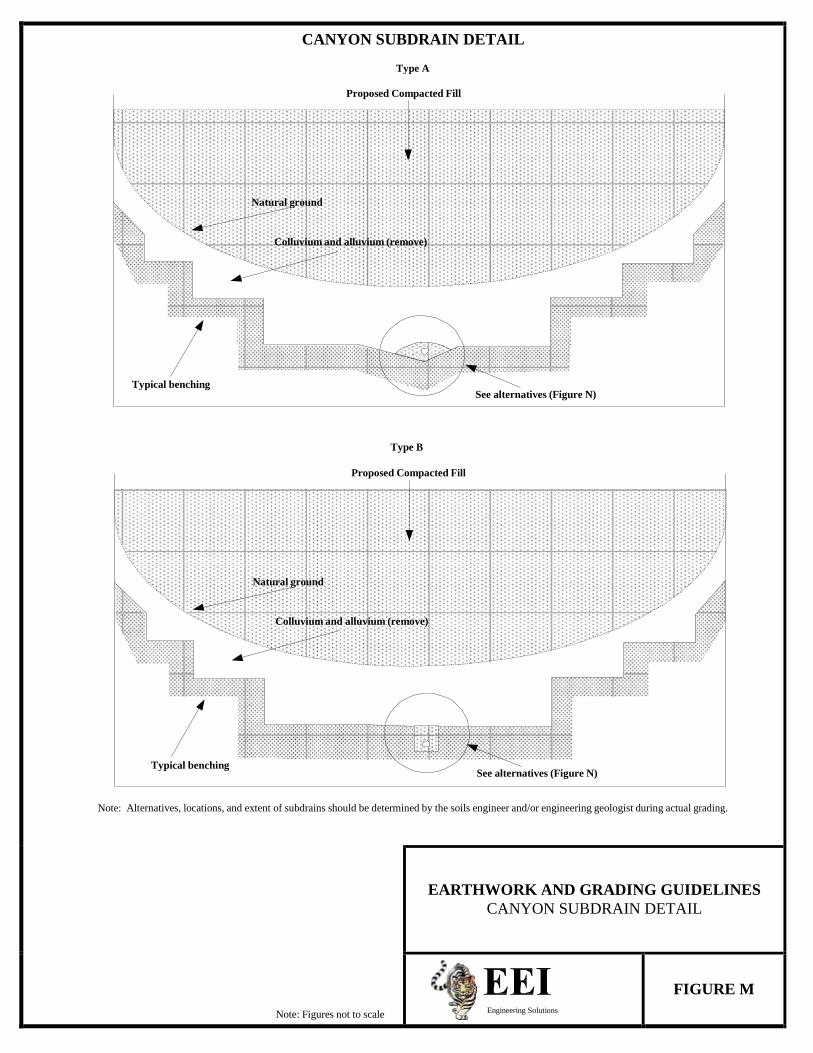
CANYON SUBDRAIN DETAIL
Type A
Proposed Compacted Fill
Natural ground
Colluvium and alluvium (remove)
Typical benching See alternatives (Figure N)
Type B
Proposed Compacted Fill
Natural ground
Colluvium and alluvium (remove)
Typical benching See alternatives (Figure N)
Note: Alternatives, locations, and extent of subdrains should be determined by the soils engineer and/or engineering geologist during actual grading.
Note: Figures not to scale
EARTHWORK AND GRADING GUIDELINES
CANYON SUBDRAIN DETAIL
Engineering Solutions
FIGURE M
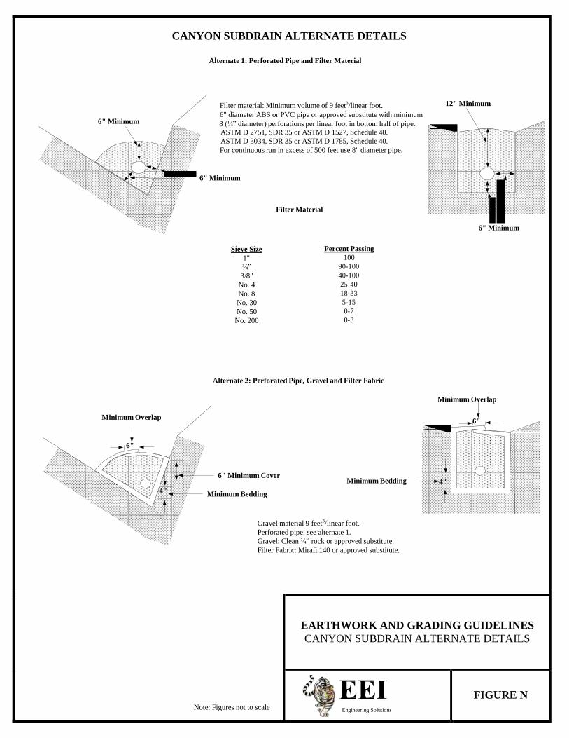
CANYON SUBDRAIN ALTERNATE DETAILS
Alternate 1: Perforated Pipe and Filter Material
Filter material: Minimum volume of 9 feet3/linear foot. 12" Minimum 6" diameter ABS or PVC pipe or approved substitute with minimum
6" Minimum 8 (¼” diameter) perforations per linear foot in bottom half of pipe. ASTM D 2751, SDR 35 or ASTM D 1527, Schedule 40. ASTM D 3034, SDR 35 or ASTM D 1785, Schedule 40. For continuous run in excess of 500 feet use 8" diameter pipe.
6" Minimum
Filter Material
6" Minimum
Sieve Size Percent Passing
1" 100 ¾” 90-100
3/8" 40-100 No. 4 25-40 No. 8 18-33 No. 30 5-15 No. 50 0-7
No. 200 0-3
Alternate 2: Perforated Pipe, Gravel and Filter Fabric
Minimum Overlap
Minimum Overlap 6"
6"
6" Minimum Cover
Minimum Bedding 4" 4" Minimum Bedding
Gravel material 9 feet3/linear foot. Perforated pipe: see alternate 1. Gravel: Clean ¾” rock or approved substitute. Filter Fabric: Mirafi 140 or approved substitute.
Note: Figures not to scale
EARTHWORK AND GRADING GUIDELINES CANYON SUBDRAIN ALTERNATE DETAILS
Engineering Solutions
FIGURE N
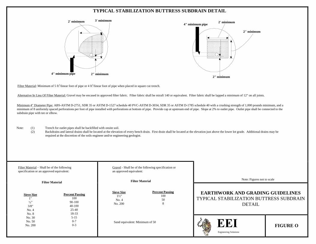
TYPICAL STABILIZATION BUTTRESS SUBDRAIN DETAIL
2' minimum 3' minimum 2' minimum
4" minimum pipe
2" minimum
4" minimum pipe 2" minimum 2" minimum
Filter Material: Minimum of 5 ft3/linear foot of pipe or 4 ft3/linear foot of pipe when placed in square cut trench.
Alternative In Lieu Of Filter Material: Gravel may be encased in approved filter fabric. Filter fabric shall be mirafi 140 or equivalent. Filter fabric shall be lapped a minimum of 12" on all joints.
Minimum 4" Diameter Pipe: ABS-ASTM D-2751, SDR 35 or ASTM D-1527 schedule 40 PVC-ASTM D-3034, SDR 35 or ASTM D-1785 schedule 40 with a crushing strength of 1,000 pounds minimum, and a minimum of 8 uniformly spaced perforations per foot of pipe installed with perforations at bottom of pipe. Provide cap at upstream end of pipe. Slope at 2% to outlet pipe. Outlet pipe shall be connected to the subdrain pipe with tee or elbow.
Note: (1) Trench for outlet pipes shall be backfilled with onsite soil. (2) Backdrains and lateral drains shall be located at the elevation of every bench drain. First drain shall be located at the elevation just above the lower lot grade. Additional drains may be
required at the discretion of the soils engineer and/or engineering geologist.
Filter Material – Shall be of the following specification or an approved equivalent:
Filter Material
Sieve Size Percent Passing 1" 100 ¾” 90-100
3/8" 40-100 No. 4 25-40 No. 8 18-33 No. 30 5-15 No. 50 0-7
No. 200 0-3
Gravel - Shall be of the following specification or an approved equivalent:
Filter Material
Sieve Size Percent Passing 1½" 100
No. 4 50 No. 200 8
Sand equivalent: Minimum of 50
Note: Figures not to scale
EARTHWORK AND GRADING GUIDELINES
TYPICAL STABILIZATION BUTTRESS SUBDRAIN DETAIL
Engineering Solutions
FIGURE O
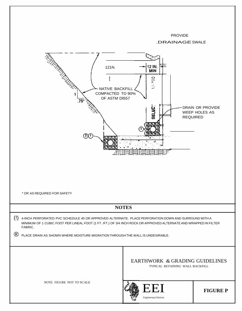
t _.
PROVIDE
.DRAINAGE SWALE
121N.
0 (t)
A
_. NATIVE BACKFILL
COMPACTED TO 90%
OF ASTM Dl557
1u
-
w_. w C/)
DRAIN OR PROVIDE
WEEP HOLES AS
REQUIRED
"11· • ••
* OR AS REQUIRED FOR SAFETY
NOTES
(!) 4-INCH PERFORATED PVC SCHEDULE 40 OR APPROVED ALTERNATE. PLACE PERFORATION DOWN AND SURROUND WITH A
MINIMUM OF 1 CUBIC FOOT PER LINEAL FOOT (1 FT. /FT.) OF 3/4 INCH ROCK OR APPROVED ALTERNATE AND WRAPPED IN FILTER
FABRIC.
® PLACE DRAIN AS SHOWN WHERE MOISTURE MIGRATION THROUGH THE WALL IS UNDESIRABLE.
EARTHWORK & GRADING GUIDELINES TYPICAL RETAINING WALL BACKFILL
NOTE: FIGURE NOT TO SCALE
EEI Engineering Solutions
FIGURE P

NWC of Cannon Road & Mystra Way Project No. 16081-01 Oceanside, California June 16, 2016
GeoMat Testing Laboratories, Inc. Page 2
ATTACHED MAPS AND APPENDICES Figure 1 Site Location Map Figure 2 Topographic Map, 1/100000 Figure 3 Topographic Map, 1/24000 Figure 4 Topographic Map, 1/6000 Figure 5 Street Level Photo Figure 6 California Setting Figure 7 Regional Geologic Map Figure 8 Regional Fault Map Figure 9 Fault Activity Map Figure 10 Regional Physiographic Map Plate 1 Exploratory Boring Location Map Plate 2 Retaining Wall Drainage Detail Appendix A References Appendix B Geotechnical Boring Log Appendix C Laboratory Test Results Appendix D CBC Seismic Design Parameters Appendix E General Earthwork and Grading Specifications Appendix F Slope Maintenance Guidelines
NWC of Cannon Road & Mystra Way Project No. 16081-01 Oceanside, California June 16, 2016
GeoMat Testing Laboratories, Inc. Page 3
SCOPE OF WORK
Review soils, seismic, groundwater data, and maps in our files.
Exploration of the site at accessible location by means of a drill rig.
Field engineer for logging, observe drilling resistance/caving.
Sampling of select soils.
Laboratory testing for classification, shear strength, expansion, and sulfate.
Prepare CBC seismic design parameters.
Preparation of a soil investigation report (3 copies) to include: Site preparation recommendations, Allowable soil bearing value, Foundation recommendations, Slab-on-grade recommendations, Earth pressures, Grading specifications, Pavement design, Site Class, CBC seismic design parameters, and cement type.
NWC of Cannon Road & Mystra Way Project No. 16081-01 Oceanside, California June 16, 2016
GeoMat Testing Laboratories, Inc. Page 4
SITE CONDITIONS AND PROPOSED DEVELOPMENT Site Condition The subject site is currently a vacant lot that is located immediately north of the intersection of Cannon Road and Mystra Way, in the city of Oceanside. Both Cannon and Mystra are paved roads with fully developed concrete curb, gutter, and sidewalks. The site is generally rectangle in shape measuring approximately 575 feet long and 270 feet wide. Access on site is off Cannon Road, from a private paved road located on the northeastern border of the lot. Several mature trees were noted along the northeastern border of the site along with several piles of dumped vegetation debris. Large cobbles and chunks of concrete were noted throughout the site. The site had probably been mass graded in cut sometime in the past and currently has a relatively flat topography. Surface sheet flow is draining towards Mystra Way at rate of approximately 1.6 percent. To total relief on site is approximately 25 feet with the highest end located on the northeastern border on the access road and the lowest elevation located in the southern corner by the Cannon-Mystra intersection. Proposed Development We understand that the site is proposed for a senior living development and the associated streets, parking spaces, driveways, etc. The structures are assumed to be one or two story wood framed units. We anticipate that the proposed structures are to be supported by a combination of isolated square and continuous wall type foundations, and concrete slabs-on-grade. We have not been provided with specific foundation loads. We anticipate however, that continuous wall loads will not exceed 2500 pounds per linear foot and isolated column loads of up to 25 kips.
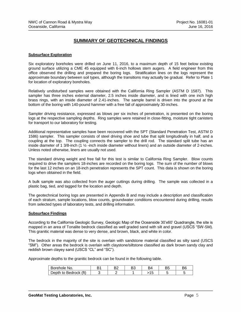
NWC of Cannon Road & Mystra Way Project No. 16081-01 Oceanside, California June 16, 2016
GeoMat Testing Laboratories, Inc. Page 5
SUMMARY OF GEOTECHNICAL FINDINGS Subsurface Exploration Six exploratory boreholes were drilled on June 11, 2016, to a maximum depth of 15 feet below existing ground surface utilizing a CME 45 equipped with 6-inch hollows stem augers. A field engineer from this office observed the drilling and prepared the boring logs. Stratification lines on the logs represent the approximate boundary between soil types, although the transitions may actually be gradual. Refer to Plate 1 for location of exploratory boreholes. Relatively undisturbed samples were obtained with the California Ring Sampler (ASTM D 1587). This sampler has three inches external diameter, 2.5 inches inside diameter, and is lined with one inch high brass rings, with an inside diameter of 2.41-inches. The sample barrel is driven into the ground at the bottom of the boring with 140-pound hammer with a free fall of approximately 30-inches. Sampler driving resistance, expressed as blows per six inches of penetration, is presented on the boring logs at the respective sampling depths. Ring samples were retained in close-fitting, moisture tight canisters for transport to our laboratory for testing. Additional representative samples have been recovered with the SPT (Standard Penetration Test, ASTM D 1586) sampler. This sampler consists of steel driving shoe and tube that split longitudinally in half, and a coupling at the top. The coupling connects the sampler to the drill rod. The standard split tube has an inside diameter of 1 3/8-inch (1 ½ -inch inside diameter without liners) and an outside diameter of 2-inches. Unless noted otherwise, liners are usually not used. The standard driving weight and free fall for this test is similar to California Ring Sampler. Blow counts required to drive the samplers 18-inches are recorded on the boring logs. The sum of the number of blows for the last 12 inches on an 18-inch penetration represents the SPT count. This data is shown on the boring logs when obtained in the field. A bulk sample was also collected from the auger cuttings during drilling. The sample was collected in a plastic bag, tied, and tagged for the location and depth. The geotechnical boring logs are presented in Appendix B and may include a description and classification of each stratum, sample locations, blow counts, groundwater conditions encountered during drilling, results from selected types of laboratory tests, and drilling information. Subsurface Findings According to the California Geologic Survey, Geologic Map of the Oceanside 30’x60’ Quadrangle, the site is mapped in an area of Tonalite bedrock classified as well graded sand with silt and gravel (USCS “SW-SM). This granitic material was dense to very dense, and brown, black, and white in color. The bedrock in the majority of the site is overlain with sandstone material classified as silty sand (USCS “SM”). Other areas the bedrock is overlain with claystone/siltstone classified as dark brown sandy clay and reddish brown clayey sand (USCS “CL” and “SC”). Approximate depths to the granitic bedrock can be found in the following table.
Borehole No. B1 B2 B3 B4 B5 B6
Depth to Bedrock (ft) 3 2 1 >15 5 5
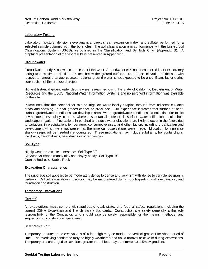
NWC of Cannon Road & Mystra Way Project No. 16081-01 Oceanside, California June 16, 2016
GeoMat Testing Laboratories, Inc. Page 6
Laboratory Testing Laboratory moisture, density, sieve analysis, direct shear, expansion index, and sulfate, performed for a selected sample obtained from the boreholes. The soil classification is in conformance with the Unified Soil Classifications System (USCS), as outlined in the Classification and Symbols Chart (Appendix B). A graphical presentation of the test results is presented in Appendix C. Groundwater Groundwater study is not within the scope of this work. Groundwater was not encountered in our exploratory boring to a maximum depth of 15 feet below the ground surface. Due to the elevation of the site with respect to natural drainage courses, regional ground water is not expected to be a significant factor during construction of the proposed project. Highest historical groundwater depths were researched using the State of California, Department of Water Resources and the USGS, National Water Information Systems and no pertinent information was available for the site. Please note that the potential for rain or irrigation water locally seeping through from adjacent elevated areas and showing up near grades cannot be precluded. Our experience indicates that surface or near-surface groundwater conditions can develop in areas where groundwater conditions did not exist prior to site development, especially in areas where a substantial increase in surface water infiltration results from landscape irrigation. Fluctuations in perched and static water elevations are likely to occur in the future due to variations in precipitation, temperature, consumptive uses, and other factors including urbanization and development which were not present at the time our observations were made. Mitigation for nuisance shallow seeps will be needed if encountered. These mitigations may include subdrains, horizontal drains, toe drains, french drains, heel drains or other devices. Soil Type Highly weathered white sandstone: Soil Type “C” Claystone/siltstone (sandy clay and clayey sand): Soil Type “B” Granitic Bedrock: Stable Rock Excavation Characteristics The subgrade soil appears to be moderately dense to dense and very firm with dense to very dense granitic bedrock. Difficult excavation in bedrock may be encountered during rough grading, utility excavation, and foundation construction. Temporary Excavations General All excavations must comply with applicable local, state, and federal safety regulations including the current OSHA Excavation and Trench Safety Standards. Construction site safety generally is the sole responsibility of the Contractor, who should also be solely responsible for the means, methods, and sequencing of construction operations. Safe Vertical Cut Temporary un-surcharged excavations of 4 feet high may be made at a vertical gradient for short period of time. The overlaying sandstone may be highly weathered and could unravel or cave-in during excavations. Temporary un-surcharged excavations greater than 4 feet may be trimmed at 1.5H:1V gradient.
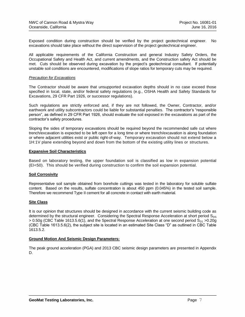
NWC of Cannon Road & Mystra Way Project No. 16081-01 Oceanside, California June 16, 2016
GeoMat Testing Laboratories, Inc. Page 7
Exposed condition during construction should be verified by the project geotechnical engineer. No excavations should take place without the direct supervision of the project geotechnical engineer. All applicable requirements of the California Construction and general Industry Safety Orders, the Occupational Safety and Health Act, and current amendments, and the Construction safety Act should be met. Cuts should be observed during excavation by the project’s geotechnical consultant. If potentially unstable soil conditions are encountered, modifications of slope ratios for temporary cuts may be required. Precaution for Excavations The Contractor should be aware that unsupported excavation depths should in no case exceed those specified in local, state, and/or federal safety regulations (e.g., OSHA Health and Safety Standards for Excavations, 29 CFR Part 1926, or successor regulations). Such regulations are strictly enforced and, if they are not followed, the Owner, Contractor, and/or earthwork and utility subcontractors could be liable for substantial penalties. The contractor’s “responsible person”, as defined in 29 CFR Part 1926, should evaluate the soil exposed in the excavations as part of the contractor’s safety procedures. Sloping the sides of temporary excavations should be required beyond the recommended safe cut where trench/excavation is expected to be left open for a long time or where trench/excavation is along foundation or where adjacent utilities exist or public right-of-way. Temporary excavation should not extend below a 1H:1V plane extending beyond and down from the bottom of the existing utility lines or structures. Expansive Soil Characteristics Based on laboratory testing, the upper foundation soil is classified as low in expansion potential (EI<50). This should be verified during construction to confirm the soil expansion potential. Soil Corrosivity Representative soil sample obtained from borehole cuttings was tested in the laboratory for soluble sulfate content. Based on the results, sulfate concentration is about 450 ppm (0.045%) in the tested soil sample. Therefore we recommend Type II cement for all concrete in contact with earth material. Site Class It is our opinion that structures should be designed in accordance with the current seismic building code as determined by the structural engineer. Considering the Spectral Response Acceleration at short period SDS > 0.50g (CBC Table 1613.5.6(1), and the Spectral Response Acceleration at one second period SD1 >0.20g (CBC Table 1613.5.6(2), the subject site is located in an estimated Site Class “D” as outlined in CBC Table 1613.5.2. Ground Motion And Seismic Design Parameters: The peak ground acceleration (PGA) and 2013 CBC seismic design parameters are presented in Appendix D.
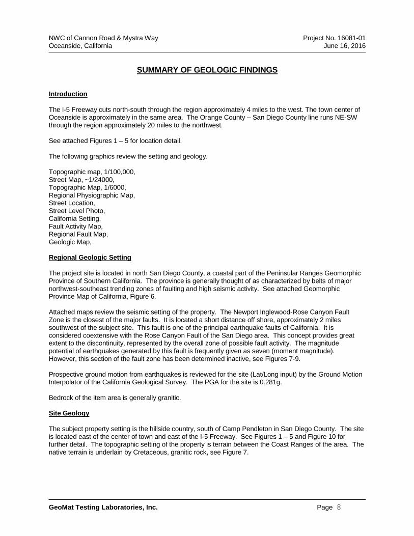
NWC of Cannon Road & Mystra Way Project No. 16081-01 Oceanside, California June 16, 2016
GeoMat Testing Laboratories, Inc. Page 8
SUMMARY OF GEOLOGIC FINDINGS Introduction The I-5 Freeway cuts north-south through the region approximately 4 miles to the west. The town center of Oceanside is approximately in the same area. The Orange County – San Diego County line runs NE-SW through the region approximately 20 miles to the northwest. See attached Figures 1 – 5 for location detail. The following graphics review the setting and geology. Topographic map, 1/100,000, Street Map, ~1/24000, Topographic Map, 1/6000, Regional Physiographic Map, Street Location, Street Level Photo, California Setting, Fault Activity Map, Regional Fault Map, Geologic Map, Regional Geologic Setting The project site is located in north San Diego County, a coastal part of the Peninsular Ranges Geomorphic Province of Southern California. The province is generally thought of as characterized by belts of major northwest-southeast trending zones of faulting and high seismic activity. See attached Geomorphic Province Map of California, Figure 6. Attached maps review the seismic setting of the property. The Newport Inglewood-Rose Canyon Fault Zone is the closest of the major faults. It is located a short distance off shore, approximately 2 miles southwest of the subject site. This fault is one of the principal earthquake faults of California. It is considered coextensive with the Rose Canyon Fault of the San Diego area. This concept provides great extent to the discontinuity, represented by the overall zone of possible fault activity. The magnitude potential of earthquakes generated by this fault is frequently given as seven (moment magnitude). However, this section of the fault zone has been determined inactive, see Figures 7-9. Prospective ground motion from earthquakes is reviewed for the site (Lat/Long input) by the Ground Motion Interpolator of the California Geological Survey. The PGA for the site is 0.281g. Bedrock of the item area is generally granitic. Site Geology The subject property setting is the hillside country, south of Camp Pendleton in San Diego County. The site is located east of the center of town and east of the I-5 Freeway. See Figures 1 – 5 and Figure 10 for further detail. The topographic setting of the property is terrain between the Coast Ranges of the area. The native terrain is underlain by Cretaceous, granitic rock, see Figure 7.
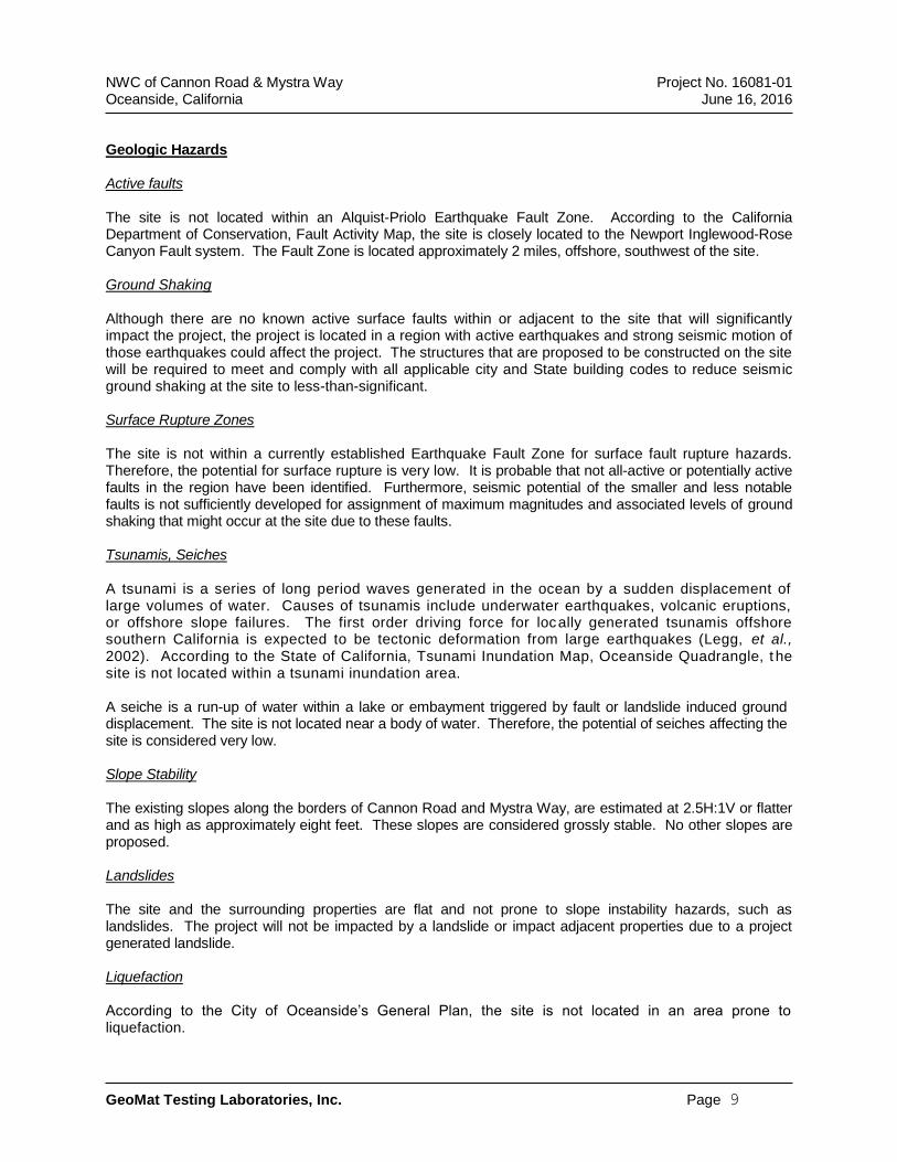
NWC of Cannon Road & Mystra Way Project No. 16081-01 Oceanside, California June 16, 2016
GeoMat Testing Laboratories, Inc. Page 9
Geologic Hazards Active faults The site is not located within an Alquist-Priolo Earthquake Fault Zone. According to the California Department of Conservation, Fault Activity Map, the site is closely located to the Newport Inglewood-Rose Canyon Fault system. The Fault Zone is located approximately 2 miles, offshore, southwest of the site. Ground Shaking Although there are no known active surface faults within or adjacent to the site that will significantly impact the project, the project is located in a region with active earthquakes and strong seismic motion of those earthquakes could affect the project. The structures that are proposed to be constructed on the site will be required to meet and comply with all applicable city and State building codes to reduce seismic ground shaking at the site to less-than-significant. Surface Rupture Zones The site is not within a currently established Earthquake Fault Zone for surface fault rupture hazards. Therefore, the potential for surface rupture is very low. It is probable that not all-active or potentially active faults in the region have been identified. Furthermore, seismic potential of the smaller and less notable faults is not sufficiently developed for assignment of maximum magnitudes and associated levels of ground shaking that might occur at the site due to these faults. Tsunamis, Seiches A tsunami is a series of long period waves generated in the ocean by a sudden displacement of large volumes of water. Causes of tsunamis include underwater earthquakes, volcanic eruptions, or offshore slope failures. The first order driving force for locally generated tsunamis offshore southern California is expected to be tectonic deformation from large earthquakes (Legg, et al., 2002). According to the State of California, Tsunami Inundation Map, Oceanside Quadrangle, t he site is not located within a tsunami inundation area. A seiche is a run-up of water within a lake or embayment triggered by fault or landslide induced ground displacement. The site is not located near a body of water. Therefore, the potential of seiches affecting the site is considered very low. Slope Stability The existing slopes along the borders of Cannon Road and Mystra Way, are estimated at 2.5H:1V or flatter and as high as approximately eight feet. These slopes are considered grossly stable. No other slopes are proposed. Landslides The site and the surrounding properties are flat and not prone to slope instability hazards, such as landslides. The project will not be impacted by a landslide or impact adjacent properties due to a project generated landslide. Liquefaction According to the City of Oceanside’s General Plan, the site is not located in an area prone to liquefaction.
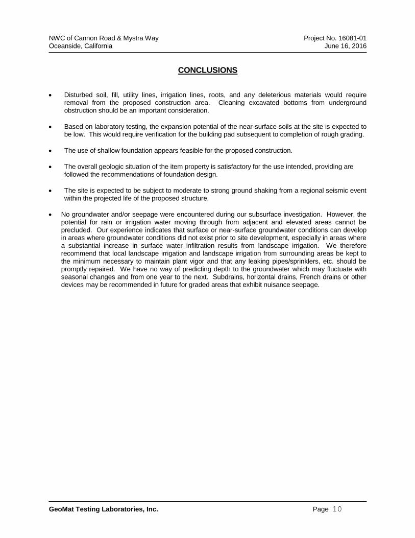
NWC of Cannon Road & Mystra Way Project No. 16081-01 Oceanside, California June 16, 2016
GeoMat Testing Laboratories, Inc. Page 10
CONCLUSIONS
Disturbed soil, fill, utility lines, irrigation lines, roots, and any deleterious materials would require removal from the proposed construction area. Cleaning excavated bottoms from underground obstruction should be an important consideration.
Based on laboratory testing, the expansion potential of the near-surface soils at the site is expected to be low. This would require verification for the building pad subsequent to completion of rough grading.
The use of shallow foundation appears feasible for the proposed construction.
The overall geologic situation of the item property is satisfactory for the use intended, providing are followed the recommendations of foundation design.
The site is expected to be subject to moderate to strong ground shaking from a regional seismic event within the projected life of the proposed structure.
No groundwater and/or seepage were encountered during our subsurface investigation. However, the potential for rain or irrigation water moving through from adjacent and elevated areas cannot be precluded. Our experience indicates that surface or near-surface groundwater conditions can develop in areas where groundwater conditions did not exist prior to site development, especially in areas where a substantial increase in surface water infiltration results from landscape irrigation. We therefore recommend that local landscape irrigation and landscape irrigation from surrounding areas be kept to the minimum necessary to maintain plant vigor and that any leaking pipes/sprinklers, etc. should be promptly repaired. We have no way of predicting depth to the groundwater which may fluctuate with seasonal changes and from one year to the next. Subdrains, horizontal drains, French drains or other devices may be recommended in future for graded areas that exhibit nuisance seepage.
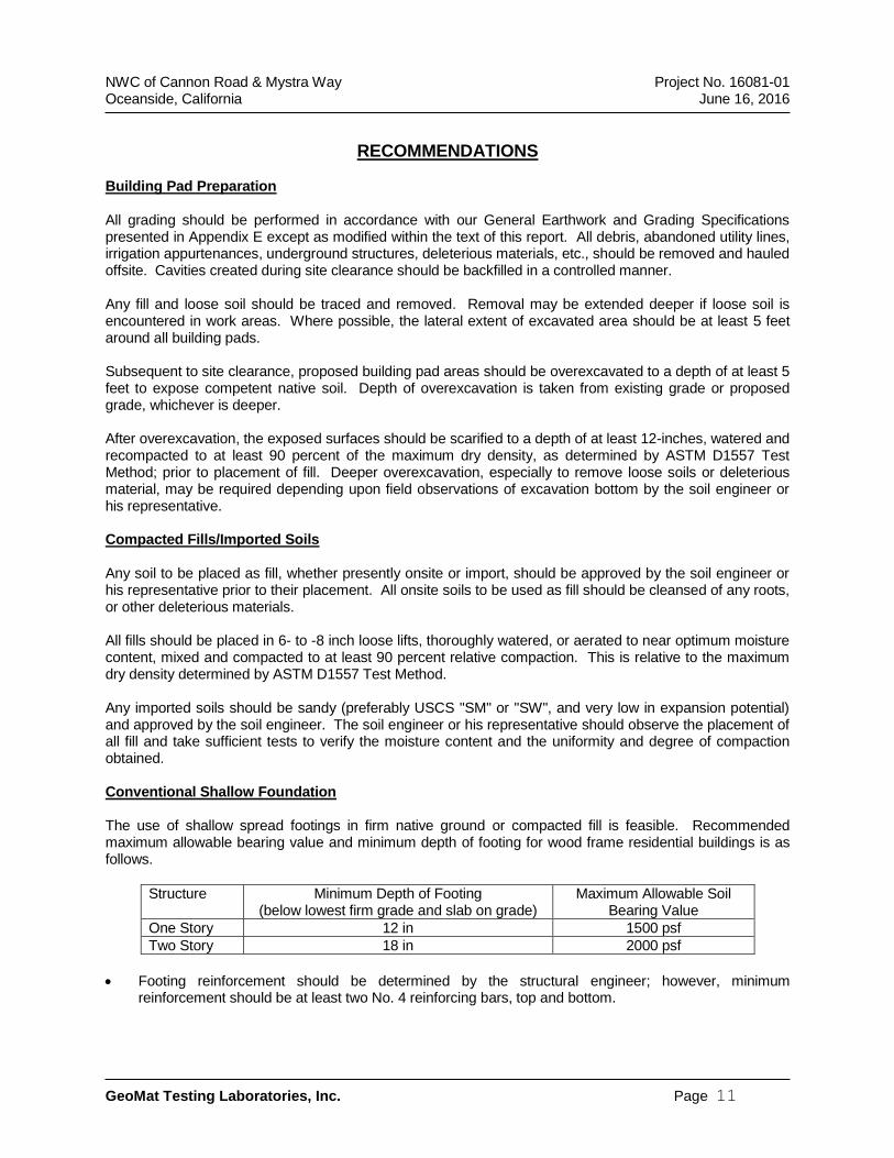
NWC of Cannon Road & Mystra Way Project No. 16081-01 Oceanside, California June 16, 2016
GeoMat Testing Laboratories, Inc. Page 11
RECOMMENDATIONS Building Pad Preparation All grading should be performed in accordance with our General Earthwork and Grading Specifications presented in Appendix E except as modified within the text of this report. All debris, abandoned utility lines, irrigation appurtenances, underground structures, deleterious materials, etc., should be removed and hauled offsite. Cavities created during site clearance should be backfilled in a controlled manner. Any fill and loose soil should be traced and removed. Removal may be extended deeper if loose soil is encountered in work areas. Where possible, the lateral extent of excavated area should be at least 5 feet around all building pads. Subsequent to site clearance, proposed building pad areas should be overexcavated to a depth of at least 5 feet to expose competent native soil. Depth of overexcavation is taken from existing grade or proposed grade, whichever is deeper. After overexcavation, the exposed surfaces should be scarified to a depth of at least 12-inches, watered and recompacted to at least 90 percent of the maximum dry density, as determined by ASTM D1557 Test Method; prior to placement of fill. Deeper overexcavation, especially to remove loose soils or deleterious material, may be required depending upon field observations of excavation bottom by the soil engineer or his representative. Compacted Fills/Imported Soils Any soil to be placed as fill, whether presently onsite or import, should be approved by the soil engineer or his representative prior to their placement. All onsite soils to be used as fill should be cleansed of any roots, or other deleterious materials. All fills should be placed in 6- to -8 inch loose lifts, thoroughly watered, or aerated to near optimum moisture content, mixed and compacted to at least 90 percent relative compaction. This is relative to the maximum dry density determined by ASTM D1557 Test Method. Any imported soils should be sandy (preferably USCS "SM" or "SW", and very low in expansion potential) and approved by the soil engineer. The soil engineer or his representative should observe the placement of all fill and take sufficient tests to verify the moisture content and the uniformity and degree of compaction obtained. Conventional Shallow Foundation The use of shallow spread footings in firm native ground or compacted fill is feasible. Recommended maximum allowable bearing value and minimum depth of footing for wood frame residential buildings is as follows.
Structure Minimum Depth of Footing (below lowest firm grade and slab on grade)
Maximum Allowable Soil Bearing Value
One Story 12 in 1500 psf
Two Story 18 in 2000 psf
Footing reinforcement should be determined by the structural engineer; however, minimum reinforcement should be at least two No. 4 reinforcing bars, top and bottom.
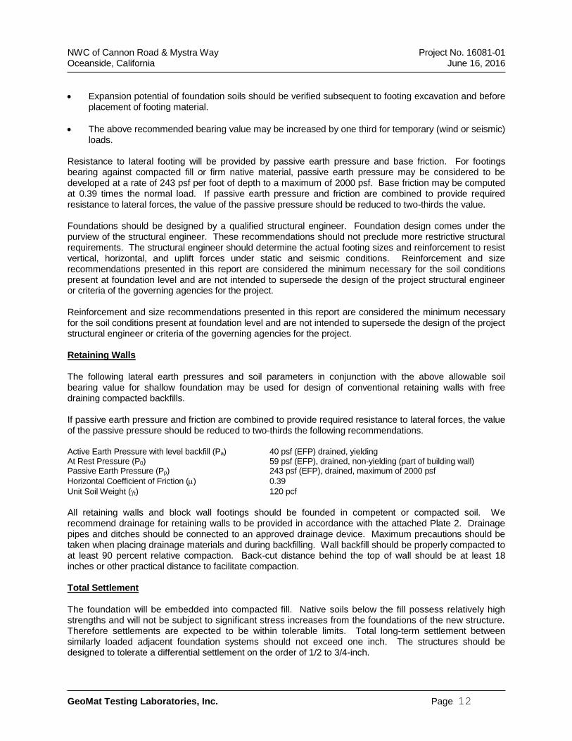
NWC of Cannon Road & Mystra Way Project No. 16081-01 Oceanside, California June 16, 2016
GeoMat Testing Laboratories, Inc. Page 12
Expansion potential of foundation soils should be verified subsequent to footing excavation and before placement of footing material.
The above recommended bearing value may be increased by one third for temporary (wind or seismic) loads.
Resistance to lateral footing will be provided by passive earth pressure and base friction. For footings bearing against compacted fill or firm native material, passive earth pressure may be considered to be developed at a rate of 243 psf per foot of depth to a maximum of 2000 psf. Base friction may be computed at 0.39 times the normal load. If passive earth pressure and friction are combined to provide required resistance to lateral forces, the value of the passive pressure should be reduced to two-thirds the value. Foundations should be designed by a qualified structural engineer. Foundation design comes under the purview of the structural engineer. These recommendations should not preclude more restrictive structural requirements. The structural engineer should determine the actual footing sizes and reinforcement to resist vertical, horizontal, and uplift forces under static and seismic conditions. Reinforcement and size recommendations presented in this report are considered the minimum necessary for the soil conditions present at foundation level and are not intended to supersede the design of the project structural engineer or criteria of the governing agencies for the project. Reinforcement and size recommendations presented in this report are considered the minimum necessary for the soil conditions present at foundation level and are not intended to supersede the design of the project structural engineer or criteria of the governing agencies for the project. Retaining Walls The following lateral earth pressures and soil parameters in conjunction with the above allowable soil bearing value for shallow foundation may be used for design of conventional retaining walls with free draining compacted backfills. If passive earth pressure and friction are combined to provide required resistance to lateral forces, the value of the passive pressure should be reduced to two-thirds the following recommendations. Active Earth Pressure with level backfill (Pa) 40 psf (EFP) drained, yielding At Rest Pressure (P0) 59 psf (EFP), drained, non-yielding (part of building wall) Passive Earth Pressure (Pp) 243 psf (EFP), drained, maximum of 2000 psf
Horizontal Coefficient of Friction () 0.39
Unit Soil Weight (t) 120 pcf
All retaining walls and block wall footings should be founded in competent or compacted soil. We recommend drainage for retaining walls to be provided in accordance with the attached Plate 2. Drainage pipes and ditches should be connected to an approved drainage device. Maximum precautions should be taken when placing drainage materials and during backfilling. Wall backfill should be properly compacted to at least 90 percent relative compaction. Back-cut distance behind the top of wall should be at least 18 inches or other practical distance to facilitate compaction. Total Settlement The foundation will be embedded into compacted fill. Native soils below the fill possess relatively high strengths and will not be subject to significant stress increases from the foundations of the new structure. Therefore settlements are expected to be within tolerable limits. Total long-term settlement between similarly loaded adjacent foundation systems should not exceed one inch. The structures should be designed to tolerate a differential settlement on the order of 1/2 to 3/4-inch.
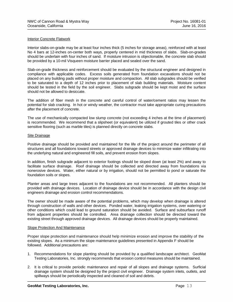
NWC of Cannon Road & Mystra Way Project No. 16081-01 Oceanside, California June 16, 2016
GeoMat Testing Laboratories, Inc. Page 13
Interior Concrete Flatwork Interior slabs-on-grade may be at least four inches thick (5 inches for storage areas), reinforced with at least No 4 bars at 12-inches on-center both ways, properly centered in mid thickness of slabs. Slab-on-grades should be underlain with four inches of sand. If moisture intrusion is objectionable, the concrete slab should be provided by a 10-mil Visqueen moisture barrier placed and sealed over the sand. Slab-on-grade thickness and reinforcement should be evaluated by the structural engineer and designed in compliance with applicable codes. Excess soils generated from foundation excavations should not be placed on any building pads without proper moisture and compaction. All slab subgrades should be verified to be saturated to a depth of 12 inches prior to placement of slab building materials. Moisture content should be tested in the field by the soil engineer. Slabs subgrade should be kept moist and the surface should not be allowed to desiccate. The addition of fiber mesh in the concrete and careful control of water/cement ratios may lessen the potential for slab cracking. In hot or windy weather, the contractor must take appropriate curing precautions after the placement of concrete. The use of mechanically compacted low slump concrete (not exceeding 4 inches at the time of placement) is recommended. We recommend that a slipsheet (or equivalent) be utilized if grouted tiles or other crack sensitive flooring (such as marble tiles) is planned directly on concrete slabs. Site Drainage Positive drainage should be provided and maintained for the life of the project around the perimeter of all structures and all foundations toward streets or approved drainage devices to minimize water infiltrating into the underlying natural and engineered fill soils, and prevent erosion from slopes. In addition, finish subgrade adjacent to exterior footings should be sloped down (at least 2%) and away to facilitate surface drainage. Roof drainage should be collected and directed away from foundations via nonerosive devices. Water, either natural or by irrigation, should not be permitted to pond or saturate the foundation soils or slopes. Planter areas and large trees adjacent to the foundations are not recommended. All planters should be provided with drainage devices. Location of drainage device should be in accordance with the design civil engineers drainage and erosion control recommendations. The owner should be made aware of the potential problems, which may develop when drainage is altered through construction of walls and other devices. Ponded water, leaking irrigation systems, over watering or other conditions which could lead to ground saturation should be avoided. Surface and subsurface runoff from adjacent properties should be controlled. Area drainage collection should be directed toward the existing street through approved drainage devices. All drainage devices should be properly maintained. Slope Protection And Maintenance Proper slope protection and maintenance should help minimize erosion and improve the stability of the existing slopes. As a minimum the slope maintenance guidelines presented in Appendix F should be followed. Additional precautions are: 1. Recommendations for slope planting should be provided by a qualified landscape architect. GeoMat
Testing Laboratories, Inc. strongly recommends that erosion control measures should be maintained.
2. It is critical to provide periodic maintenance and repair of all slopes and drainage systems. Surficial drainage system should be designed by the project civil engineer. Drainage system inlets, outlets, and spillways should be periodically inspected and cleaned of soil and debris.
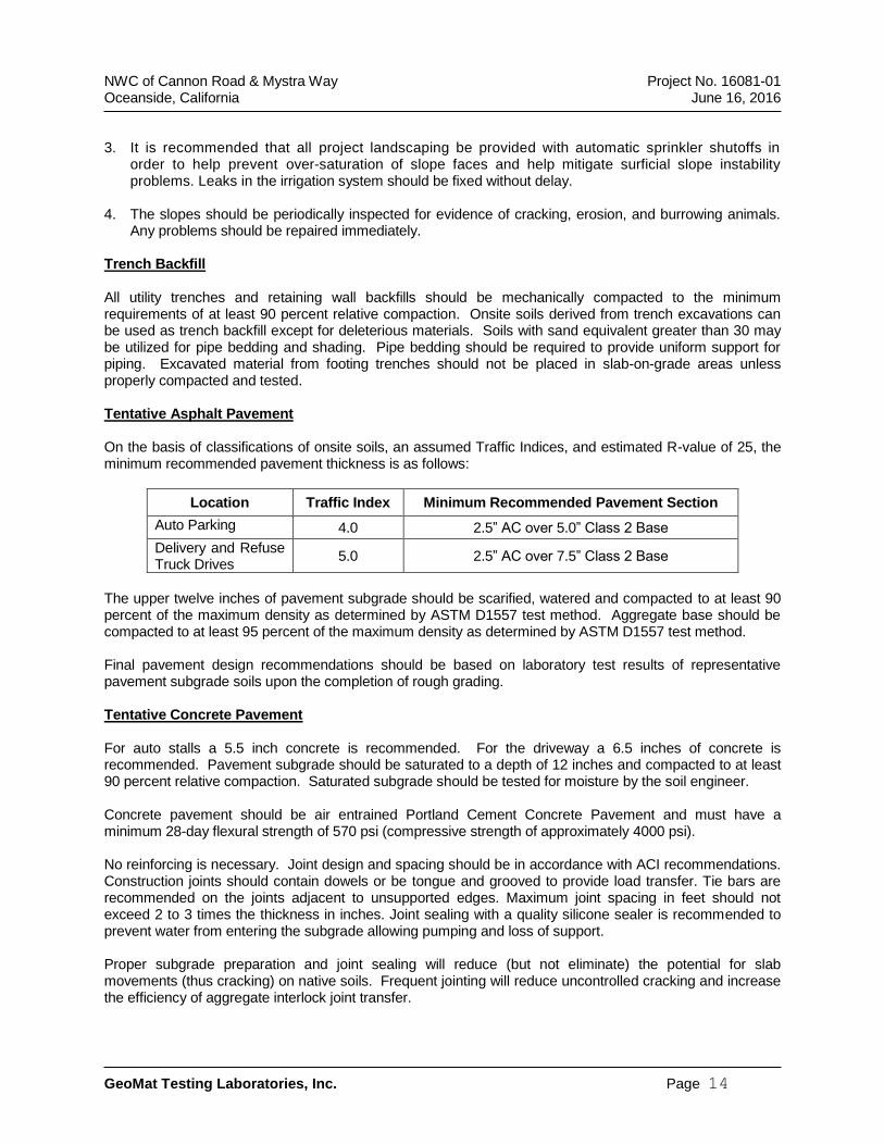
NWC of Cannon Road & Mystra Way Project No. 16081-01 Oceanside, California June 16, 2016
GeoMat Testing Laboratories, Inc. Page 14
3. It is recommended that all project landscaping be provided with automatic sprinkler shutoffs in
order to help prevent over-saturation of slope faces and help mitigate surficial slope instability problems. Leaks in the irrigation system should be fixed without delay.
4. The slopes should be periodically inspected for evidence of cracking, erosion, and burrowing animals.
Any problems should be repaired immediately. Trench Backfill All utility trenches and retaining wall backfills should be mechanically compacted to the minimum requirements of at least 90 percent relative compaction. Onsite soils derived from trench excavations can be used as trench backfill except for deleterious materials. Soils with sand equivalent greater than 30 may be utilized for pipe bedding and shading. Pipe bedding should be required to provide uniform support for piping. Excavated material from footing trenches should not be placed in slab-on-grade areas unless properly compacted and tested. Tentative Asphalt Pavement On the basis of classifications of onsite soils, an assumed Traffic Indices, and estimated R-value of 25, the minimum recommended pavement thickness is as follows:
Location Traffic Index Minimum Recommended Pavement Section
Auto Parking 4.0 2.5” AC over 5.0” Class 2 Base
Delivery and Refuse Truck Drives
5.0 2.5” AC over 7.5” Class 2 Base
The upper twelve inches of pavement subgrade should be scarified, watered and compacted to at least 90 percent of the maximum density as determined by ASTM D1557 test method. Aggregate base should be compacted to at least 95 percent of the maximum density as determined by ASTM D1557 test method. Final pavement design recommendations should be based on laboratory test results of representative pavement subgrade soils upon the completion of rough grading. Tentative Concrete Pavement For auto stalls a 5.5 inch concrete is recommended. For the driveway a 6.5 inches of concrete is recommended. Pavement subgrade should be saturated to a depth of 12 inches and compacted to at least 90 percent relative compaction. Saturated subgrade should be tested for moisture by the soil engineer. Concrete pavement should be air entrained Portland Cement Concrete Pavement and must have a minimum 28-day flexural strength of 570 psi (compressive strength of approximately 4000 psi). No reinforcing is necessary. Joint design and spacing should be in accordance with ACI recommendations. Construction joints should contain dowels or be tongue and grooved to provide load transfer. Tie bars are recommended on the joints adjacent to unsupported edges. Maximum joint spacing in feet should not exceed 2 to 3 times the thickness in inches. Joint sealing with a quality silicone sealer is recommended to prevent water from entering the subgrade allowing pumping and loss of support. Proper subgrade preparation and joint sealing will reduce (but not eliminate) the potential for slab movements (thus cracking) on native soils. Frequent jointing will reduce uncontrolled cracking and increase the efficiency of aggregate interlock joint transfer.
NWC of Cannon Road & Mystra Way Project No. 16081-01 Oceanside, California June 16, 2016
GeoMat Testing Laboratories, Inc. Page 15
Trash Enclosure The trash enclosure slab should consist of a minimum 4 inches concrete over a minimum 4 inches of compacted Class 2 aggregate base. At a minimum, the trash enclosure slab should be reinforced with #4 rebars (both ways) at 12-inch center-to-center spacing. The required slab thickness and reinforcement should be designed by the project structural engineer. Shrinkage control and construction joints should be considered by the trash enclosure slab designer. Based on our previous experience, there is a tendency for early pavement damage in front of the trash enclosure area, where heavy wheel loads are concentrated in the same location. To enhance the durability of this paved area and reduce maintenance costs, a concrete stress apron consisting of a minimum 8 inches concrete over a minimum 12 inches of compacted Class 2 aggregate base. Concrete pavement should be air entrained Portland Cement Concrete Pavement and must have a minimum 28-day flexural strength of 570 psi (compressive strength of approximately 4000 psi). At a minimum, the concrete apron pavement should be reinforced with #4 rebar (both ways) at 12-inch center-to-center spacing. Shrinkage control and construction joints should be considered by the PCC pavement designer. The apron should be installed to cover the front of the enclosure and extend out an additional 8 feet minimum from the enclosure opening. The aggregate base should be placed in thin lifts in a manner to prevent segregation; uniformly moisture conditioned to near optimum moisture content, and compacted to at least 95 percent relative compaction to provide a smooth, unyielding surface. The upper 12 inches of subgrade under the concrete stress apron should be saturated, tested for saturation, and re-compacted to at least 90 percent relative compaction. We Should be Retained for Plan Reviews The recommendations provided in this report are based on preliminary information and subsurface conditions as interpreted from limited exploratory trenches at the site. We should be retained to review final grading and foundation plans to revise our conclusions and recommendations, as necessary. Professional fees will apply for each review. Our conclusions and recommendations should also be reviewed and verified during site grading, and revised accordingly if exposed geotechnical conditions vary from our preliminary findings and interpretations. Additional Observation and/or Testing GeoMat Testing Laboratories, Inc. should observe and/or test at the following stages of construction. • During overexcavation and backfills. • Following footing excavation and prior to placement of footing materials. • During wetting of slab subgrade and prior to placement of slab materials. • During all trench and wall backfill. • When any unusual conditions are encountered. Final Report of Compaction During Grading A final report of compaction control should be prepared subsequent to the completion of grading. The report should include a summary of work performed, laboratory test results, and the results and locations of field density tests performed during grading.
NWC of Cannon Road & Mystra Way Project No. 16081-01 Oceanside, California June 16, 2016
GeoMat Testing Laboratories, Inc. Page 16
GEOTECHNICAL RISK The concept of risk is an important aspect of the geotechnical evaluation. The primary reason for this is that the analytical methods used to develop geotechnical recommendations do not comprise an exact science. The analytical tools which geotechnical engineers use are generally empirical and must be used in conjunction with engineering judgment and experience. Therefore, the solutions and recommendations presented in the geotechnical evaluation should not be considered risk-free and, more importantly, are not a guarantee that the interaction between the soils and the proposed structure will perform as planned. The engineering recommendations presented in the preceding sections constitute GeoMat Testing Laboratories professional estimate of those measures that are necessary for the proposed structure to perform according to the proposed design based on the information generated and referenced during this evaluation, and GeoMat Testing Laboratories experience in working with these conditions.
LIMITATION OF INVESTIGATION This report was prepared for the exclusive use of the owner and project team. The use by others, or for the purposes other than intended, is at the user’s sole risk. Our investigation was performed using the degree of care and skill ordinarily exercised, under similar circumstances, by reputable Geotechnical Engineers practicing in this or similar locations within the limitations of scope, schedule, and budget. No other warranty, expressed or implied, is made as to the conclusions and professional advice included in this report. The field and laboratory test data are believed representative of the site; however, soil conditions can vary significantly. As in most projects, conditions revealed during construction may be at variance with preliminary findings. If this condition occurs, the possible variations must be evaluated by the Project Geotechnical Engineer and adjusted as required or alternate design recommended. This report is issued with the understanding that it is the responsibility of the owner, or his representative, to ensure that the information and recommendations contained herein are brought to the attention of the architect and engineer and incorporated into the plans, and the necessary steps are taken to see that the contractor and subcontractor carry out such recommendations in the field. This firm does not practice or consult in the field of safety engineering. We do not direct the contractor's operations, and we cannot be responsible for other than our own personnel on the site; therefore, the safety of others is the responsibility of the contractor. The contractor should notify the owner if he considers any of the recommended actions presented herein to be unsafe. The findings, conclusions, and recommendations presented herein are based on our understanding of the project and on subsurface conditions observed during our site work, and are valid as of the present date. However, changes in the conditions of a property can occur with the passage of time, whether they be due to natural processes or the works of man on this or adjacent properties. In additions, changes in applicable or appropriate standards may occur, whether they result from legislation or the broadening of knowledge. The findings of this report are valid as of the present date. However, changes in the conditions of a property can occur with the passage of time, whether they be due to natural processes or the works of man on this or adjacent properties. In additions, changes in applicable or appropriate standards may occur, whether they result from legislation or the broadening of knowledge.
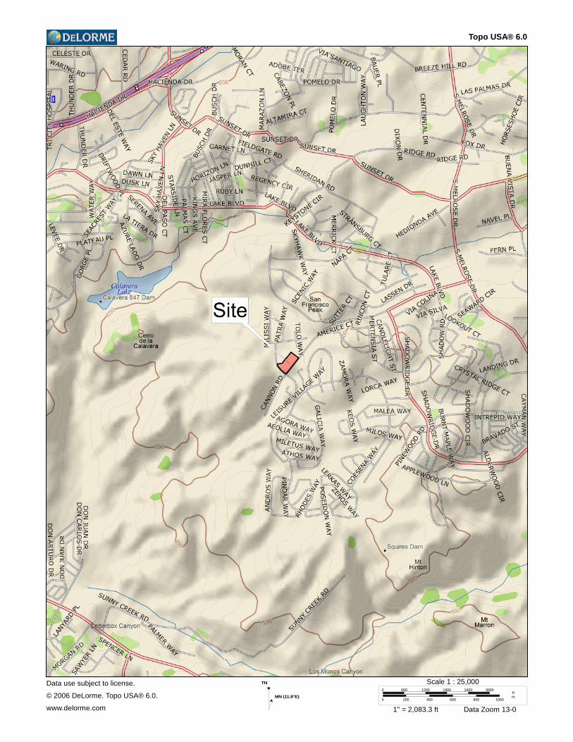
Topo USA® 6.0
Data use subject to license.
© 2006 DeLorme. Topo USA® 6.0.
www.delorme.com
TN
MN (11.8°E)
0 600 1200 1800 2400 3000
0 200 400 600 800 1000
ftm
Scale 1 : 25,000
1" = 2,083.3 ft Data Zoom 13-0
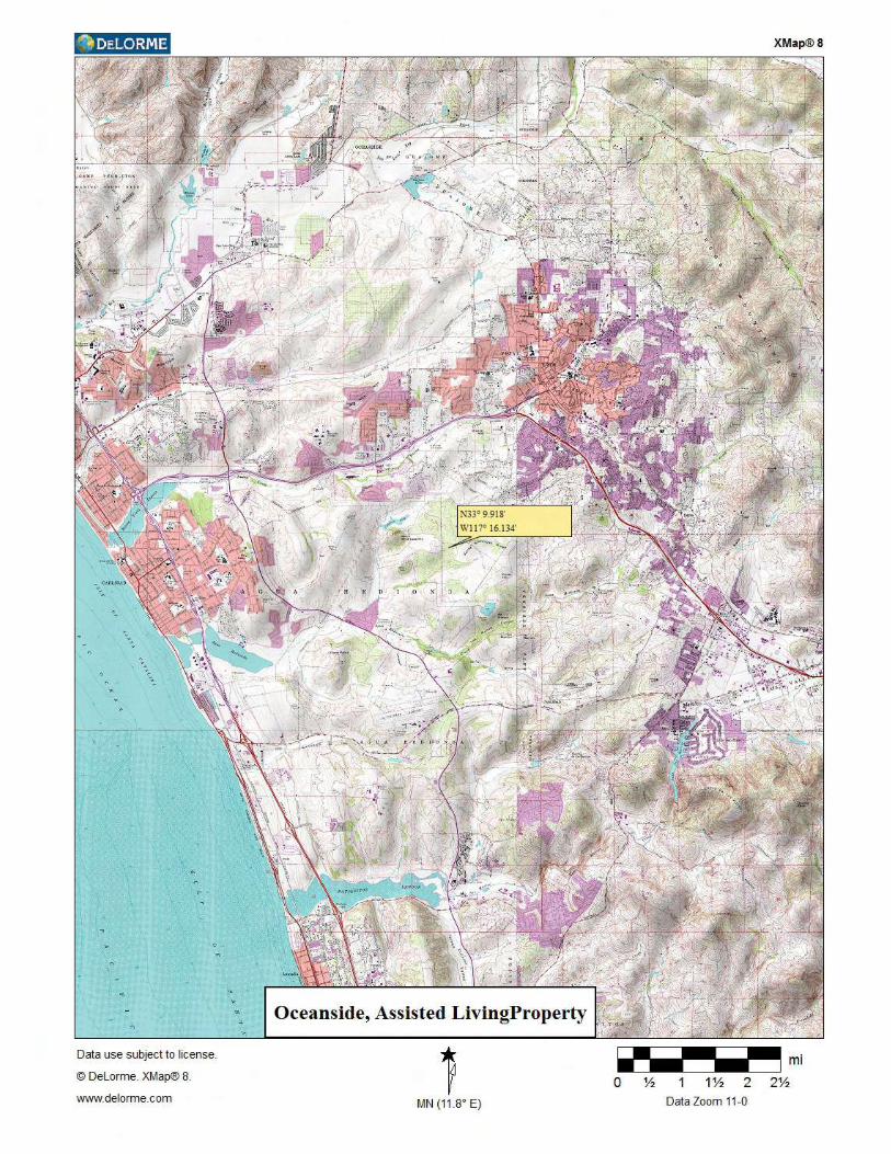
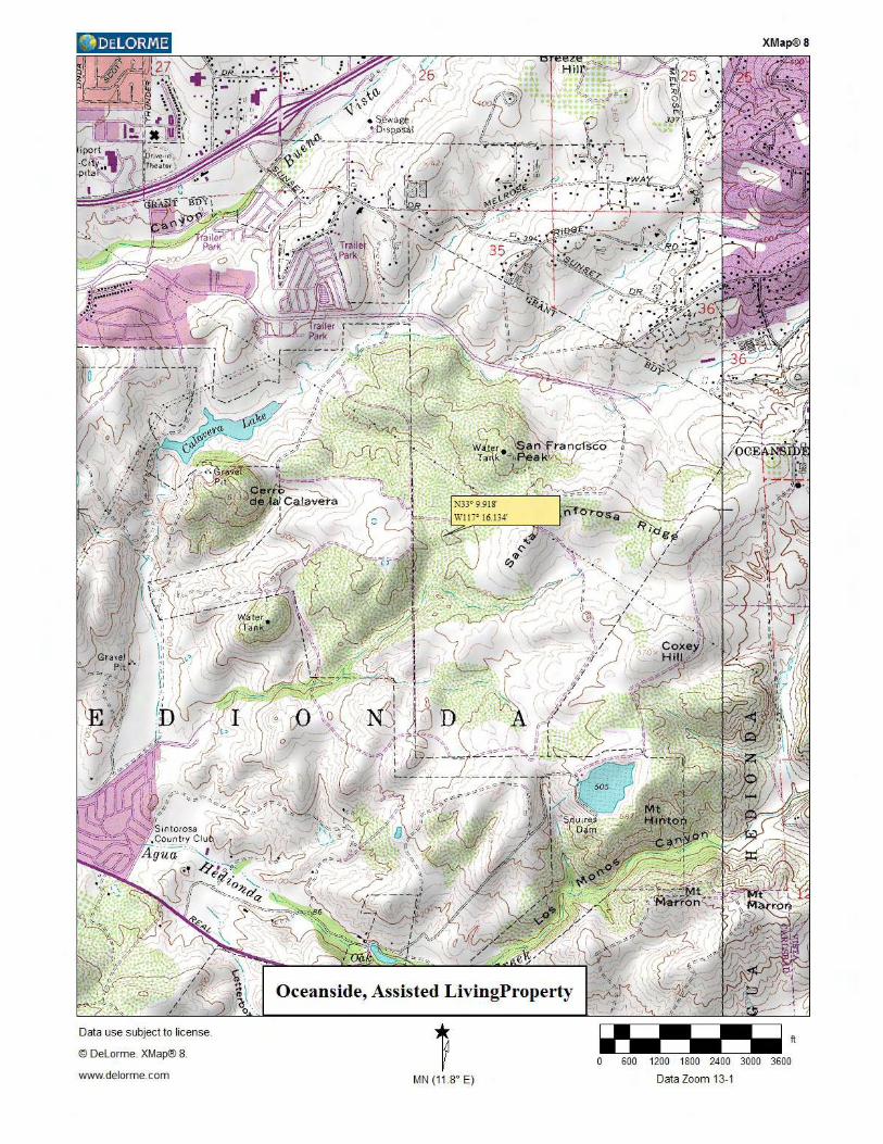
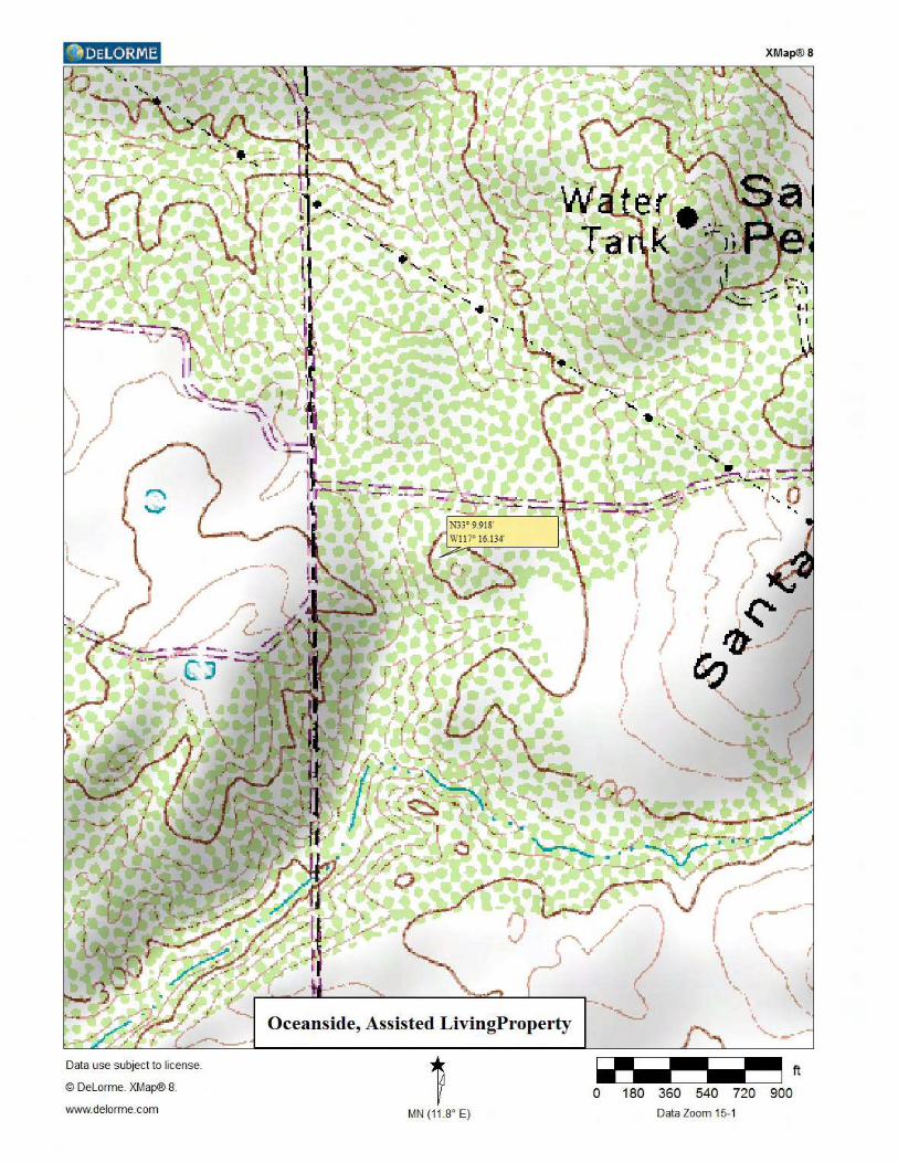

Site, street level
Cannon Rd. Cannon Rd.
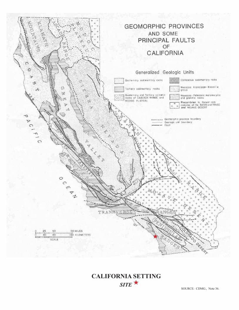
SITE
CALIFORNIA SETTING
SOURCE: CDMG., Note 36.
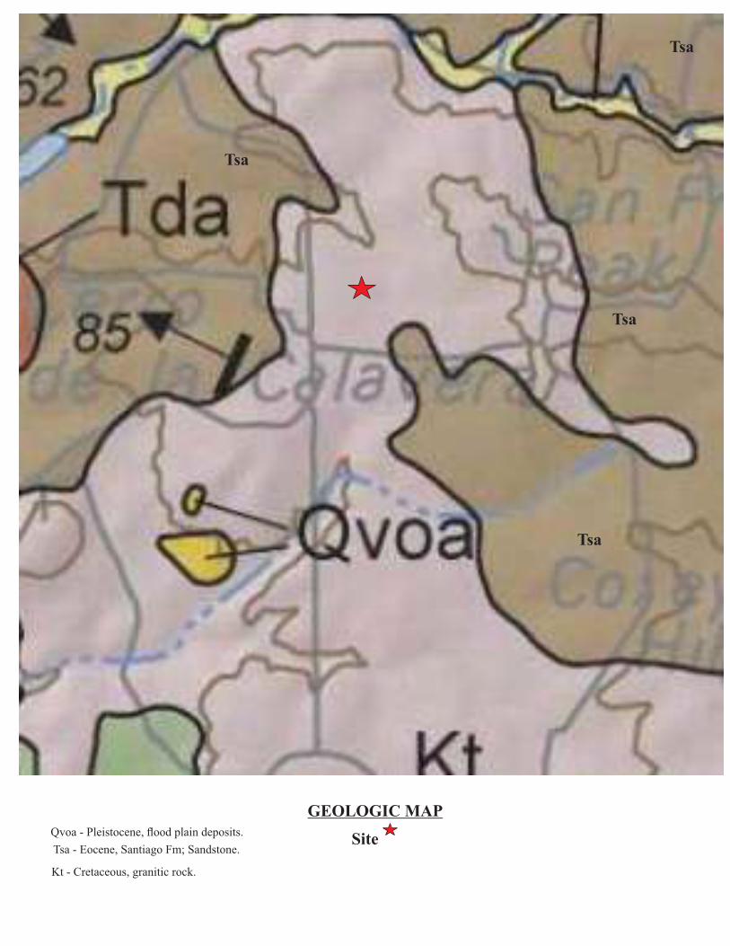
GEOLOGIC MAPQvoa - Pleistocene, flood plain deposits.
Tsa
Tsa
Tsa
Tsa
Tsa - Eocene, Santiago Fm; Sandstone.
Kt - Cretaceous, granitic rock.
Site
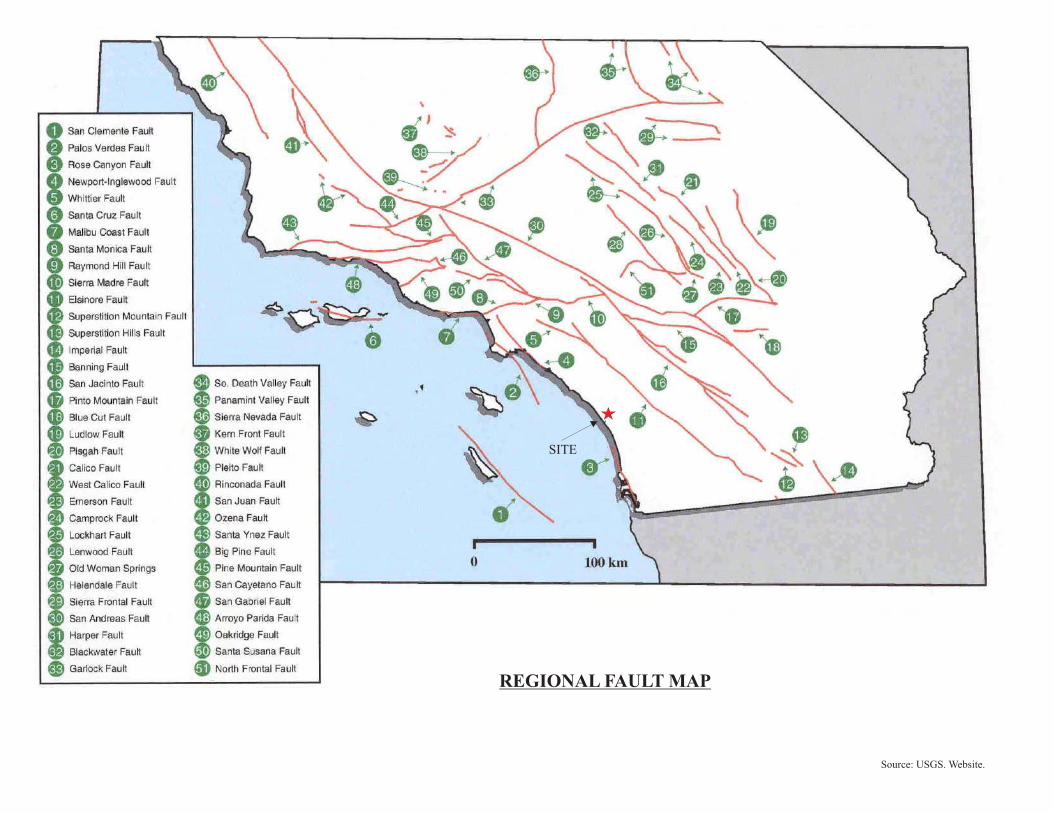
REGIONAL FAULT MAP
Source: USGS. Website.
SITE
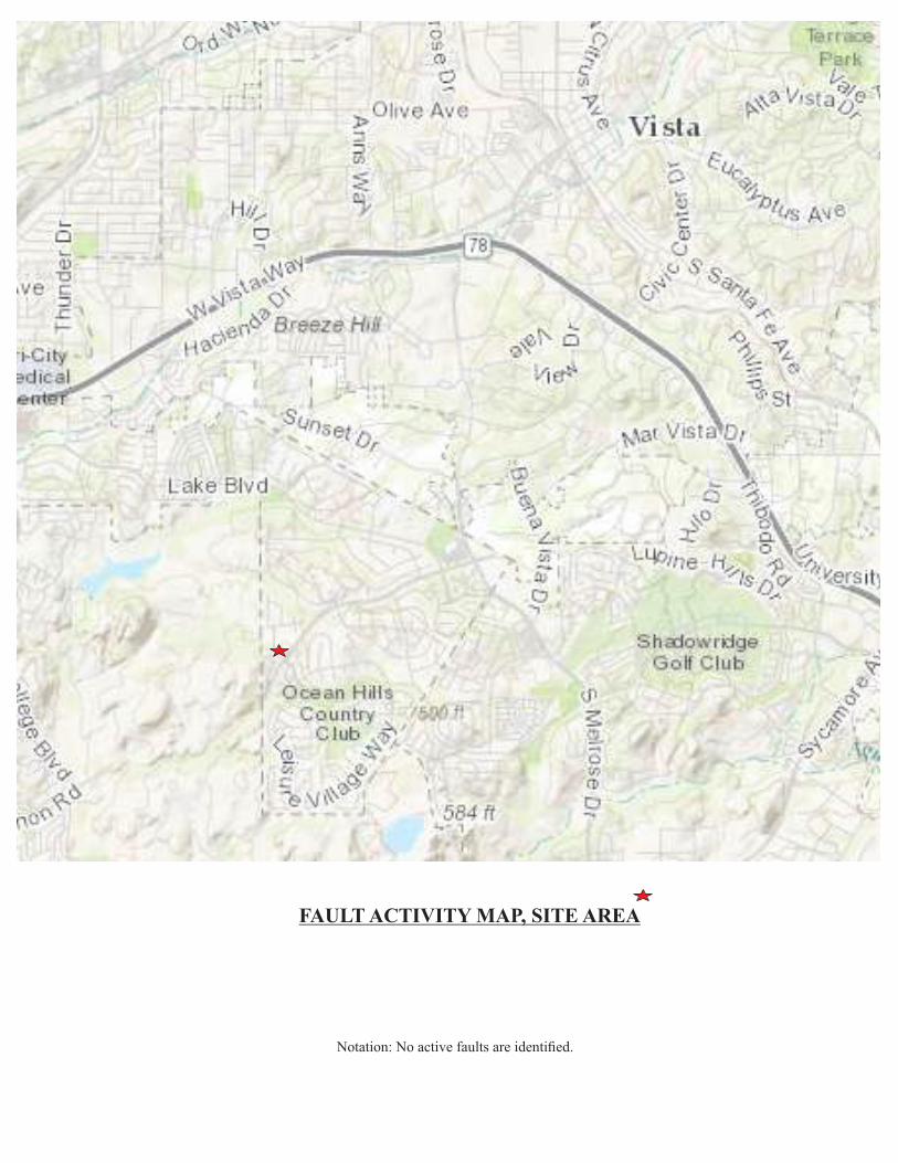
FAULT ACTIVITY MAP, SITE AREA
Notation: No active faults are identified.
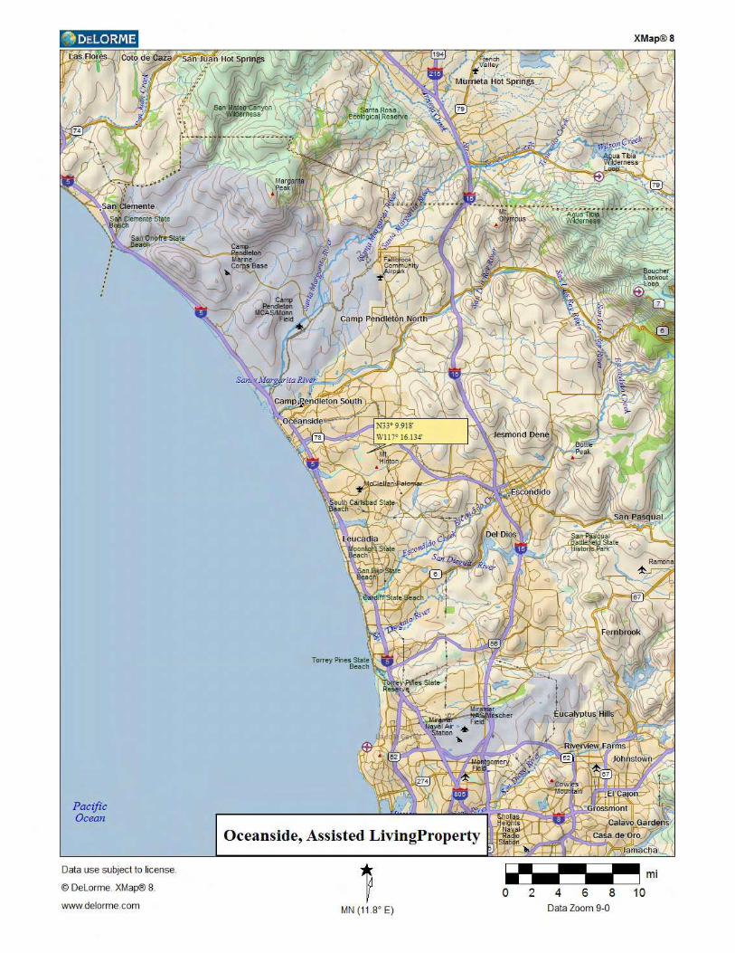
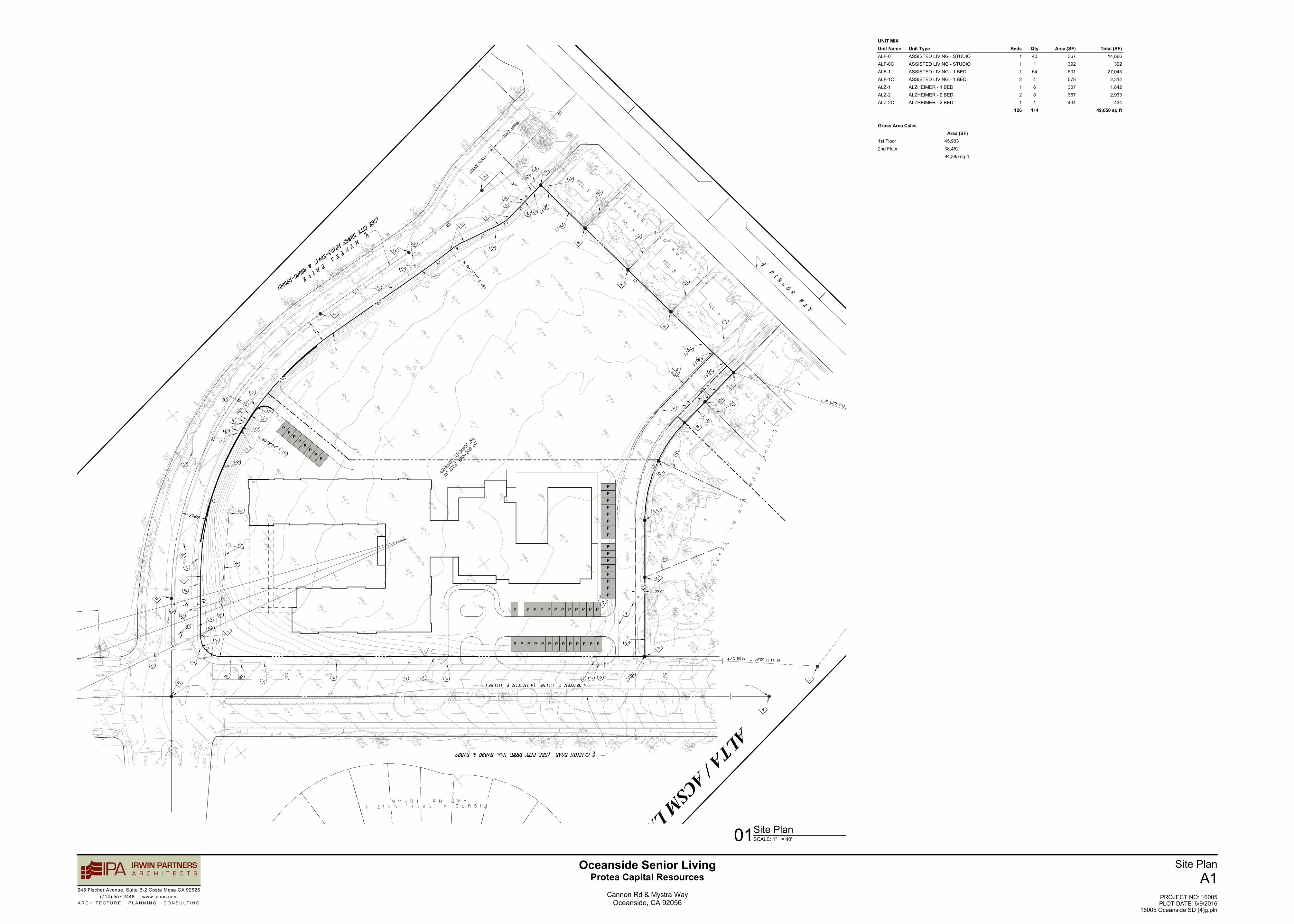
245 Fischer Avenue, Suite B-2 Costa Mesa CA 92626(714) 557 2448 www.ipaoc.com
A R C H I T E C T U R E P L A N N I N G C O N S U L T I N G
Oceanside Senior LivingProtea Capital Resources
Cannon Rd & Mystra WayOceanside, CA 92056
Site PlanA1
PROJECT NO: 16005PLOT DATE: 6/9/2016
16005 Oceanside SD (4)g.pln
PPPPPPP
PPPPPP
P P P P P P P P
P
P P
P P P P P P P P P
P
P P
P
PP
P
P
PP
PP
PP
PP
UNIT MIXUnit NameALF-0ALF-0CALF-1ALF-1CALZ-1ALZ-2ALZ-2C
Unit TypeASSISTED LIVING - STUDIOASSISTED LIVING - STUDIOASSISTED LIVING - 1 BEDASSISTED LIVING - 1 BEDALZHEIMER - 1 BEDALZHEIMER - 2 BEDALZHEIMER - 2 BED
Beds1112121
126
Qty401544681
114
Area (SF)367392501578307367434
Total (SF)14,666
39227,0432,3141,8422,933
43449,650 sq ft
Gross Area Calcs
1st Floor2nd Floor
Area (SF)45,93338,45284,385 sq ft
SCALE: 1" = 40'01Site Plan
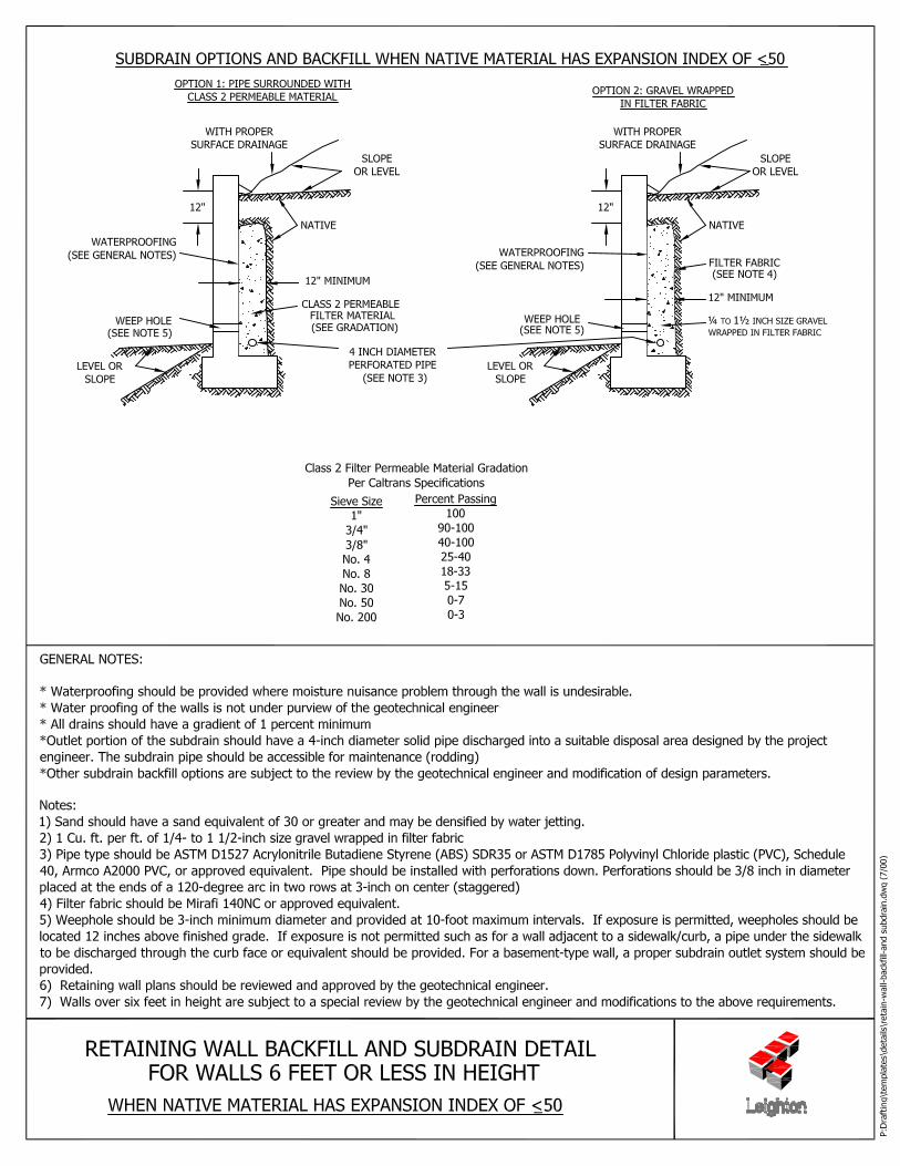

Appendix A
NWC of Cannon Road & Mystra Way Project No. 16081-01 Oceanside, California June 16, 2016
GeoMat Testing Laboratories, Inc. Appendix A
REFERENCES Kennedy, M.P., Tan, S.S., Bovard, K.R., Alvarez, R.M., Watson, M.J., and Gutierrez, C.I., 2007, Geologic map of the Oceanside 30x60-minute quadrangle, California: California Geological Survey, Regional Geologic Map No. 2, scale 1:100,000 City of Oceanside General Plan, Public Safety Element. State of California, Tsunami Inundation Map for Emergency Planning, Oceanside Quadrangle, San Luis Rey Quadrangle, June 1, 2009. State of California Department of Water Resources. USGS, Groundwater Information System. Department of the Navy, Design Manual 7.01, Soil Mechanics, September 1986. Department of the Navy, Design Manual 7.02, Foundation and Earth Structures, September 1986. California Geological Survey, Interactive Ground Motion Map, Peak Ground Acceleration (10 percent of being exceeded in 50 years). USGS, Seismic Hazard Curves, Response Parameters, and Design Parameters. Alam Singh, Modern Geotechnical Engineering, Third Edition. Department of the Army, US Army Corps of Engineers, Engineering and Design, Bearing Capacity of Soils, EM 1110-1-1905. Principals of Foundation Design, Braja Das. Foundation Analysis and Design, Ed. 5 by Joseph E. Bowles. Robert Day, Geotechnical Engineer’s Portable Handbook. Robert Day, Geotechnical Foundation Handbook.
NWC of Cannon Road & Mystra Way Project No. 16081-01 Oceanside, California June 16, 2016
GeoMat Testing Laboratories, Inc. Appendix A
BIBLIOGRAPHY
Association of Engineering Geologists, Southern California Section, Special Publication, Geology, Seismicity, and Environmental Impact, 1973. Association of Engineering Geologists, Southern California Section, Special Publication 4, Engineering Geology Practice in Southern California, 1992. Bell, F. G. (Ed.), 1994, Engineering in Rock Masses: Oxford, London, Boston, Butterworth-Heinemann Ltd (member Reed Elsevier group), 580p. CDMG, 2005, Geologic Map of the Oceanside 30’ x 60’ Quadrangle, Regional Geologic Map Series. CGS, 2008, Ground Motion Interpolator, digital input of seismicity, from digital input of site location. CDMG, Alquist Priolo Zones, Southern California, CD-ROM and website. CGS, 2010 Fault Activity Map of California. C.G.S. Map Sheet 48 (Revised), Earthquake Shaking Potential Map of California, December 23, 2008. CDMG, Note 36, Geomorphic Provinces and Some Principal Faults of California, 1986. Grant, Lisa B., and others, 1999, Late Quaternary Uplift and Earthquake Potential of the San Joaquin Hills, Southern Los Angeles Basin, Calif.: Geology, v. 27, no.11, p. 1031-1034. GSA., Geology of North America, V. G-3, the Cordilleran Orogen: Conterminous U.S., 1992. GSA., Memoir 178, the San Andreas Fault System: Displacement, Palinspastic Reconstruction, and Geologic Evolution, 1993.
Slosson, J. E., and others (Eds.), 1992, Landslides/Landslide Mitigation: Geol. Soc. Am. Reviews in Engineering Geology, V. IX, 120p. USGS, Professional Paper 1515, The San Andreas Fault System, Calif., 1990. USGS, 1989, MF-1964, Map Showing Late Quaternary Faults and 1978-84 Seismicity of the Los Angeles Region, California. Varnes, David J., 1978, Slope Movement and Types and Processes in Landslides: Analysis and Control, Transportation Research Board, National Academy of Sciences, Wash D. C., Sp. Rpt. 176, Chap. 2. Websites: CDMG, USGS, SCEDC, USGS & AASG.
Appendix B
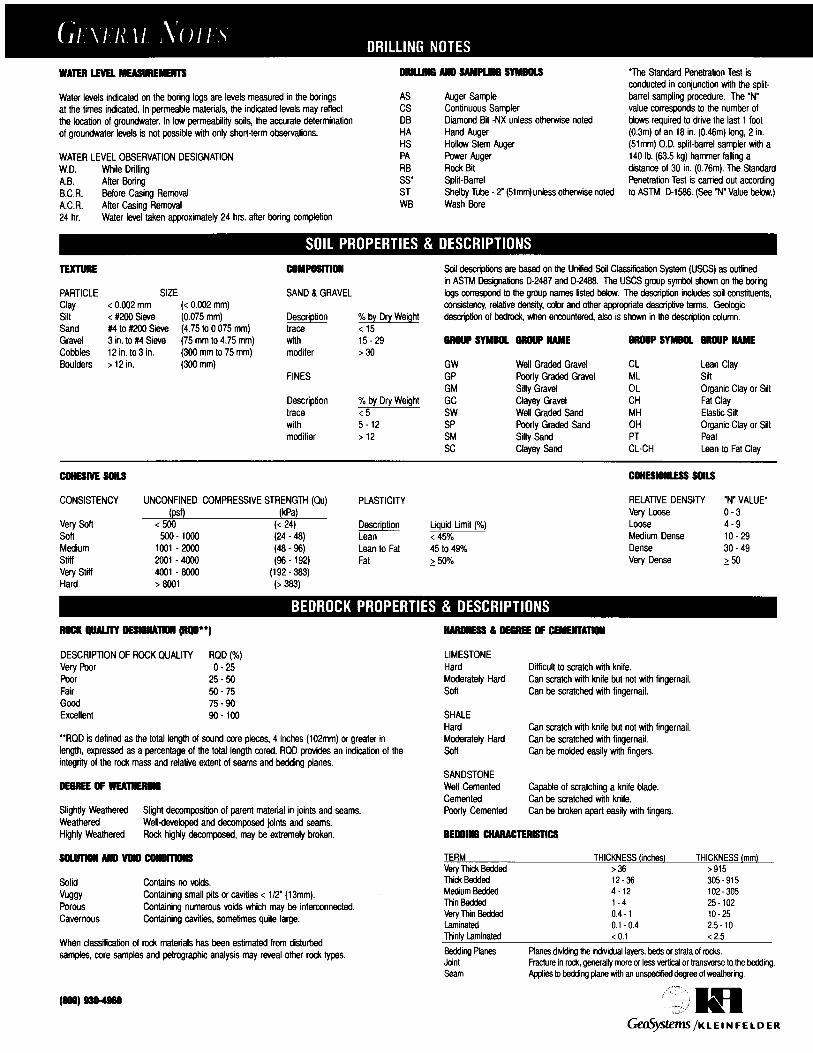
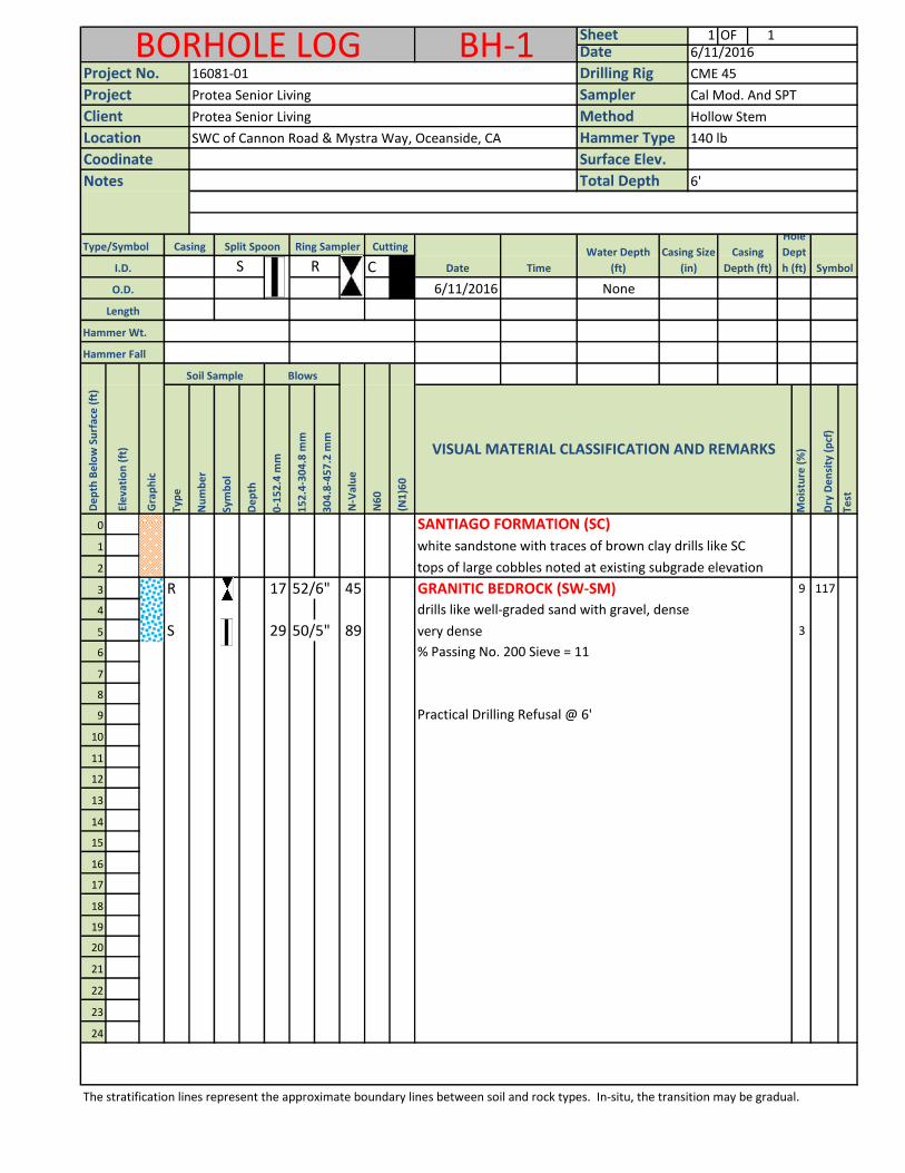
1 OF 1
Type/Symbol
C
6/11/2016 None
Hammer Wt.
Hammer Fall
Typ
e
Nu
mb
er
Sym
bo
l
De
pth
0-1
52
.4 m
m
15
2.4
-30
4.8
mm
30
4.8
-45
7.2
mm
Mo
istu
re (
%)
Dry
De
nsi
ty (
pcf
)
Test
0
1
2
3 R 17 52/6" 45 GRANITIC BEDROCK (SW-SM) 9 117
4 drills like well-graded sand with gravel, dense
5 S 29 50/5" 89 very dense 3
6
7
8
9
10
11
12
13
14
15
16
17
18
19
20
21
22
23
24
The stratification lines represent the approximate boundary lines between soil and rock types. In-situ, the transition may be gradual.
BORHOLE LOG BH-1 Sheet6/11/2016
Sampler
Drilling Rig
Date
Cal Mod. And SPT
Hollow Stem
Project
16081-01
Protea Senior Living
Protea Senior Living
Symbol
Hole
Dept
h (ft)
Casing
Depth (ft)
Casing Size
(in)
tops of large cobbles noted at existing subgrade elevation
Ring Sampler Cutting
Notes
Project No.
Client
Total Depth
Surface Elev.
Method
Hammer Type 140 lb
6'
CME 45
Location SWC of Cannon Road & Mystra Way, Oceanside, CA
Coodinate
Date Time
Gra
ph
ic
Ele
vati
on
(ft
)
De
pth
Be
low
Su
rfac
e (
ft)
Casing Split Spoon
I.D.
O.D.
Length
S
BlowsSoil Sample
VISUAL MATERIAL CLASSIFICATION AND REMARKS
Water Depth
(ft)R
N6
0
N-V
alu
e
(N1
)60
Practical Drilling Refusal @ 6'
SANTIAGO FORMATION (SC)
% Passing No. 200 Sieve = 11
white sandstone with traces of brown clay drills like SC
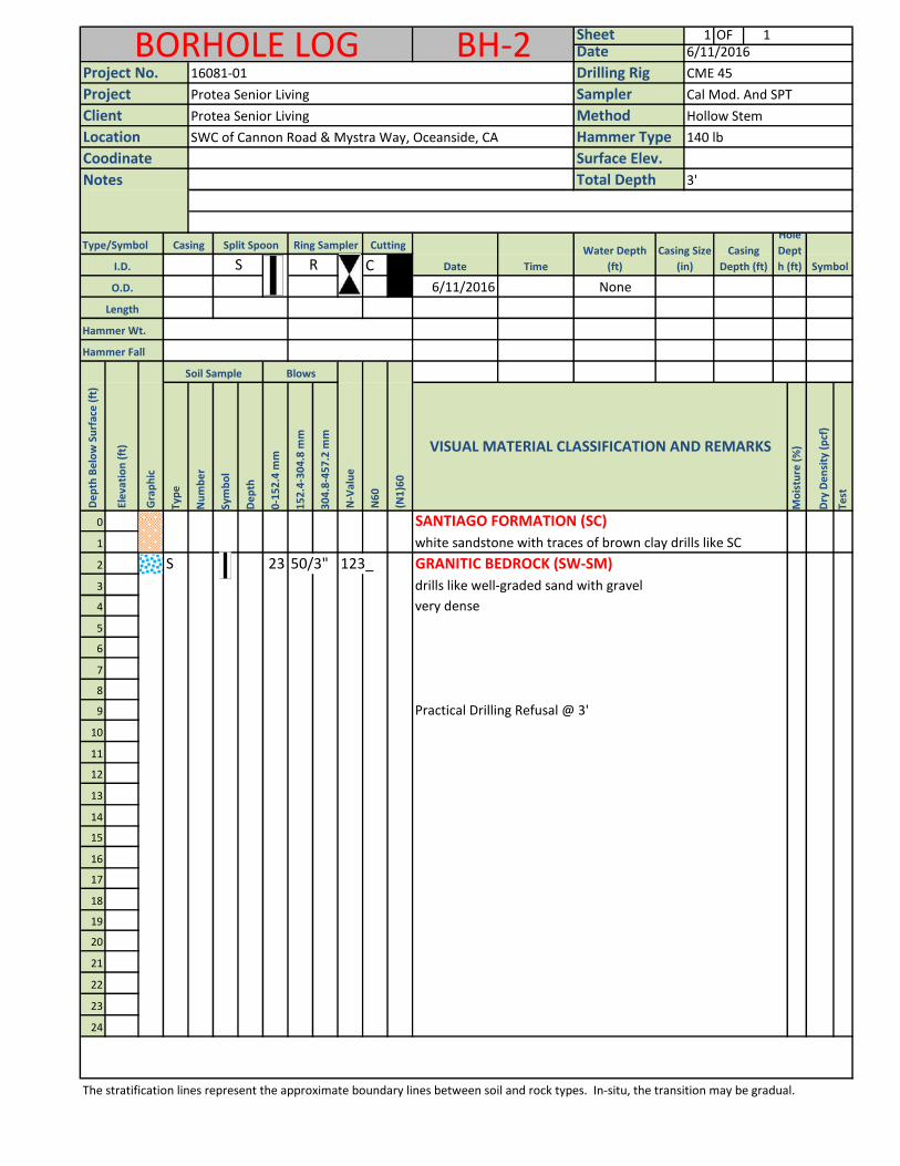
1 OF 1
Type/Symbol
C
6/11/2016 None
Hammer Wt.
Hammer Fall
Typ
e
Nu
mb
er
Sym
bo
l
De
pth
0-1
52
.4 m
m
15
2.4
-30
4.8
mm
30
4.8
-45
7.2
mm
Mo
istu
re (
%)
Dry
De
nsi
ty (
pcf
)
Test
0
1
2 S 23 50/3" 123_ GRANITIC BEDROCK (SW-SM)
3 drills like well-graded sand with gravel
4
5
6
7
8
9
10
11
12
13
14
15
16
17
18
19
20
21
22
23
24
The stratification lines represent the approximate boundary lines between soil and rock types. In-situ, the transition may be gradual.
Practical Drilling Refusal @ 3'
SANTIAGO FORMATION (SC)
white sandstone with traces of brown clay drills like SC
very dense
VISUAL MATERIAL CLASSIFICATION AND REMARKS
Water Depth
(ft)R
N6
0
N-V
alu
e
(N1
)60
Gra
ph
ic
Ele
vati
on
(ft
)
De
pth
Be
low
Su
rfac
e (
ft)
Casing Split Spoon
I.D.
O.D.
Length
S
BlowsSoil Sample
Ring Sampler Cutting
Notes
Project No.
Client
Total Depth
Surface Elev.
Method
Hammer Type 140 lb
3'
CME 45
Location SWC of Cannon Road & Mystra Way, Oceanside, CA
Coodinate
Date Time
BORHOLE LOG BH-2 Sheet6/11/2016
Sampler
Drilling Rig
Date
Cal Mod. And SPT
Hollow Stem
Project
16081-01
Protea Senior Living
Protea Senior Living
Symbol
Hole
Dept
h (ft)
Casing
Depth (ft)
Casing Size
(in)
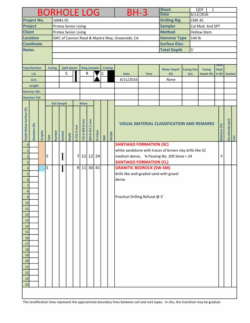
1 OF 1
Type/Symbol
C
6/11/2016 None
Hammer Wt.
Hammer Fall
Typ
e
Nu
mb
er
Sym
bo
l
De
pth
0-1
52
.4 m
m
15
2.4
-30
4.8
mm
30
4.8
-45
7.2
mm
Mo
istu
re (
%)
Dry
De
nsi
ty (
pcf
)
Test
0
1
2 S 7 12 12 24 9
3
4 S 9 11 30 41
5 drills like well-graded sand with gravel
6
7
8
9
10
11
12
13
14
15
16
17
18
19
20
21
22
23
24
The stratification lines represent the approximate boundary lines between soil and rock types. In-situ, the transition may be gradual.
Practical Drilling Refusal @ 5'
SANTIAGO FORMATION (CL)
SANTIAGO FORMATION (SC)
dense
white sandstone with traces of brown clay drills like SC
GRANITIC BEDROCK (SW-SM)
VISUAL MATERIAL CLASSIFICATION AND REMARKS
Water Depth
(ft)R
N6
0
N-V
alu
e
(N1
)60
Time
Gra
ph
ic
Ele
vati
on
(ft
)
De
pth
Be
low
Su
rfac
e (
ft)
Casing Split Spoon
I.D.
O.D.
Length
S
BlowsSoil Sample
Ring Sampler Cutting
Notes
Project No.
Client
Total Depth
Surface Elev.
Method
Hammer Type 140 lb
5'
CME 45
Location SWC of Cannon Road & Mystra Way, Oceanside, CA
Coodinate
Date
BORHOLE LOG BH-3 Sheet6/11/2016
Sampler
Drilling Rig
Date
Cal Mod. And SPT
Hollow Stem
Project
16081-01
Protea Senior Living
Protea Senior Living
Symbol
Hole
Dept
h (ft)
Casing
Depth (ft)
Casing Size
(in)
medium dense, % Passing No. 200 Sieve = 24
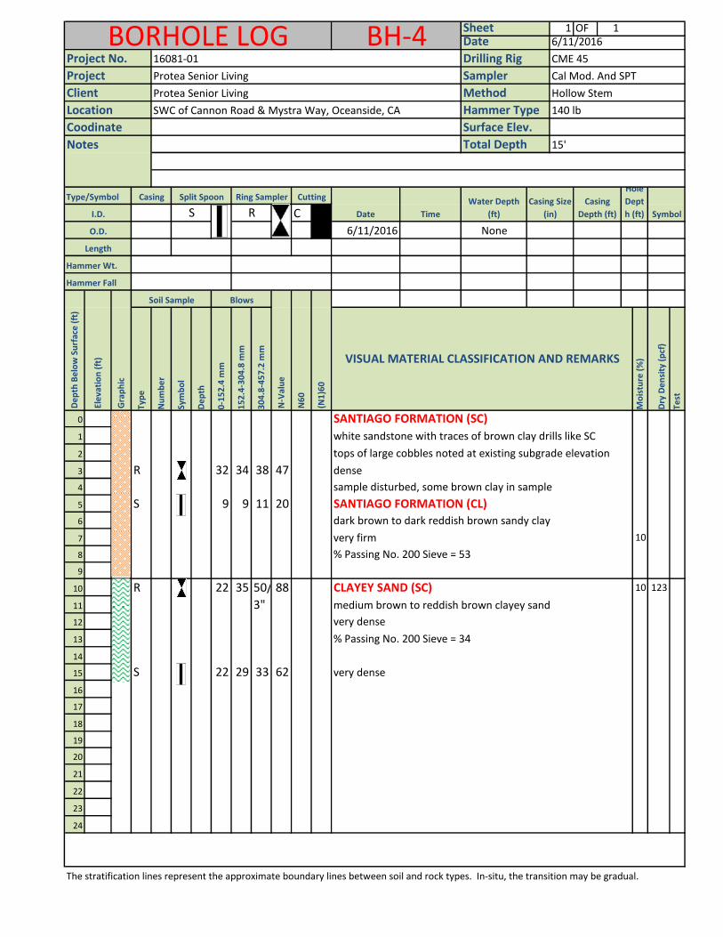
1 OF 1
Type/Symbol
C
6/11/2016 None
Hammer Wt.
Hammer Fall
Typ
e
Nu
mb
er
Sym
bo
l
De
pth
0-1
52
.4 m
m
15
2.4
-30
4.8
mm
30
4.8
-45
7.2
mm
Mo
istu
re (
%)
Dry
De
nsi
ty (
pcf
)
Test
0
1
2
3 R 32 34 38 47
4
5 S 9 9 11 20
6
7 10
8
9
10 R 22 35 50/ 88 10 123
11 3"
12 very dense
13
14
15 S 22 29 33 62
16
17
18
19
20
21
22
23
24
The stratification lines represent the approximate boundary lines between soil and rock types. In-situ, the transition may be gradual.
BORHOLE LOG BH-4 Sheet6/11/2016
Sampler
Drilling Rig
Date
Cal Mod. And SPT
Hollow Stem
Project
16081-01
Protea Senior Living
Protea Senior Living
Symbol
Hole
Dept
h (ft)
Casing
Depth (ft)
Casing Size
(in)
tops of large cobbles noted at existing subgrade elevation
Ring Sampler Cutting
Notes
Project No.
Client
Total Depth
Surface Elev.
Method
Hammer Type 140 lb
15'
CME 45
Location SWC of Cannon Road & Mystra Way, Oceanside, CA
Coodinate
Date Time
Gra
ph
ic
Ele
vati
on
(ft
)
De
pth
Be
low
Su
rfac
e (
ft)
Casing Split Spoon
I.D.
O.D.
Length
S
BlowsSoil Sample
VISUAL MATERIAL CLASSIFICATION AND REMARKS
Water Depth
(ft)R
N6
0
N-V
alu
e
(N1
)60
% Passing No. 200 Sieve = 53
medium brown to reddish brown clayey sand
dense
very firm
SANTIAGO FORMATION (SC)
dark brown to dark reddish brown sandy clay
CLAYEY SAND (SC)
very dense
white sandstone with traces of brown clay drills like SC
sample disturbed, some brown clay in sample
SANTIAGO FORMATION (CL)
% Passing No. 200 Sieve = 34
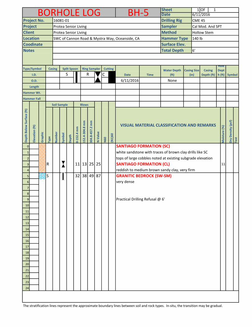
1 OF 1
Type/Symbol
C
6/11/2016 None
Hammer Wt.
Hammer Fall
Typ
e
Nu
mb
er
Sym
bo
l
De
pth
0-1
52
.4 m
m
15
2.4
-30
4.8
mm
30
4.8
-45
7.2
mm
Mo
istu
re (
%)
Dry
De
nsi
ty (
pcf
)
Test
0
1
2
3 R 11 13 25 25 11
4
5 S 32 38 49 87 GRANITIC BEDROCK (SW-SM)
6 very dense
7
8
9
10
11
12
13
14
15
16
17
18
19
20
21
22
23
24
The stratification lines represent the approximate boundary lines between soil and rock types. In-situ, the transition may be gradual.
Practical Drilling Refusal @ 6'
SANTIAGO FORMATION (CL)
SANTIAGO FORMATION (SC)
white sandstone with traces of brown clay drills like SC
reddish to medium brown sandy clay, very firm
VISUAL MATERIAL CLASSIFICATION AND REMARKS
Water Depth
(ft)R
N6
0
N-V
alu
e
(N1
)60
Time
Gra
ph
ic
Ele
vati
on
(ft
)
De
pth
Be
low
Su
rfac
e (
ft)
Casing Split Spoon
I.D.
O.D.
Length
S
BlowsSoil Sample
Ring Sampler Cutting
Notes
Project No.
Client
Total Depth
Surface Elev.
Method
Hammer Type 140 lb
6'
CME 45
Location SWC of Cannon Road & Mystra Way, Oceanside, CA
Coodinate
Date
BORHOLE LOG BH-5 Sheet6/11/2016
Sampler
Drilling Rig
Date
Cal Mod. And SPT
Hollow Stem
Project
16081-01
Protea Senior Living
Protea Senior Living
Symbol
Hole
Dept
h (ft)
Casing
Depth (ft)
Casing Size
(in)
tops of large cobbles noted at existing subgrade elevation
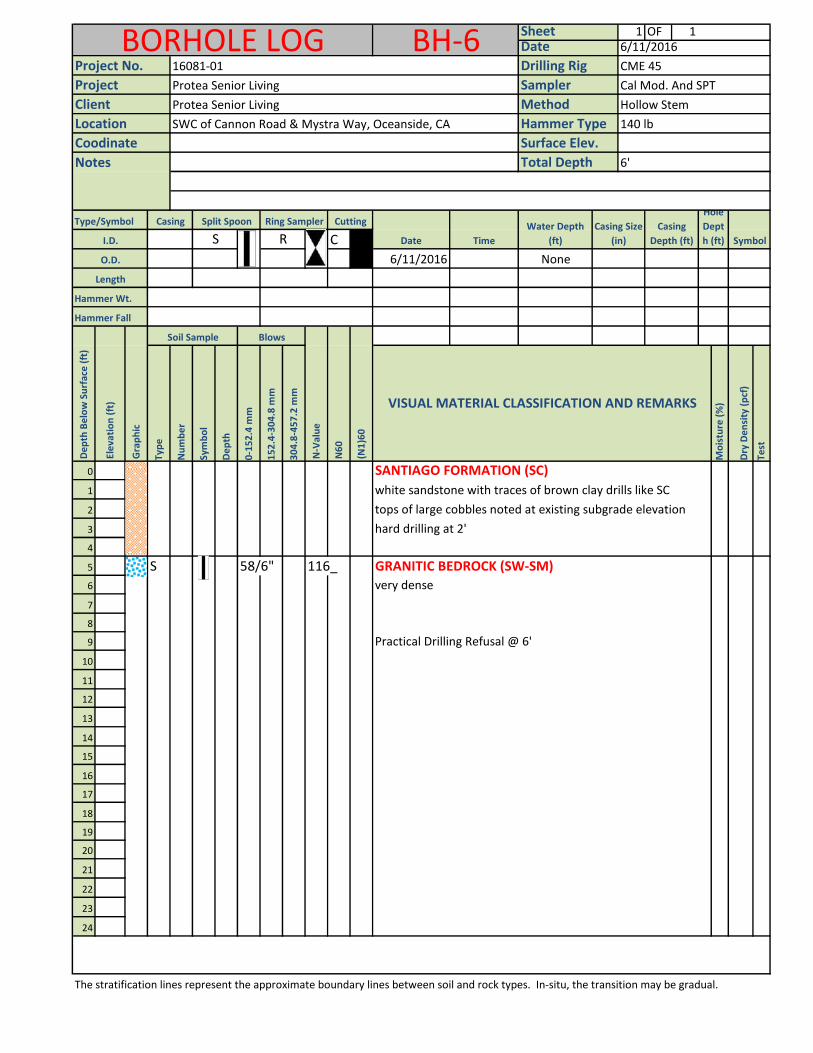
1 OF 1
Type/Symbol
C
6/11/2016 None
Hammer Wt.
Hammer Fall
Typ
e
Nu
mb
er
Sym
bo
l
De
pth
0-1
52
.4 m
m
15
2.4
-30
4.8
mm
30
4.8
-45
7.2
mm
Mo
istu
re (
%)
Dry
De
nsi
ty (
pcf
)
Test
0
1
2
3
4
5 S 58/6" 116_ GRANITIC BEDROCK (SW-SM)
6 very dense
7
8
9
10
11
12
13
14
15
16
17
18
19
20
21
22
23
24
The stratification lines represent the approximate boundary lines between soil and rock types. In-situ, the transition may be gradual.
Practical Drilling Refusal @ 6'
hard drilling at 2'
SANTIAGO FORMATION (SC)
white sandstone with traces of brown clay drills like SC
VISUAL MATERIAL CLASSIFICATION AND REMARKS
Water Depth
(ft)R
N6
0
N-V
alu
e
(N1
)60
Time
Gra
ph
ic
Ele
vati
on
(ft
)
De
pth
Be
low
Su
rfac
e (
ft)
Casing Split Spoon
I.D.
O.D.
Length
S
BlowsSoil Sample
Ring Sampler Cutting
Notes
Project No.
Client
Total Depth
Surface Elev.
Method
Hammer Type 140 lb
6'
CME 45
Location SWC of Cannon Road & Mystra Way, Oceanside, CA
Coodinate
Date
BORHOLE LOG BH-6 Sheet6/11/2016
Sampler
Drilling Rig
Date
Cal Mod. And SPT
Hollow Stem
Project
16081-01
Protea Senior Living
Protea Senior Living
Symbol
Hole
Dept
h (ft)
Casing
Depth (ft)
Casing Size
(in)
tops of large cobbles noted at existing subgrade elevation
Appendix C
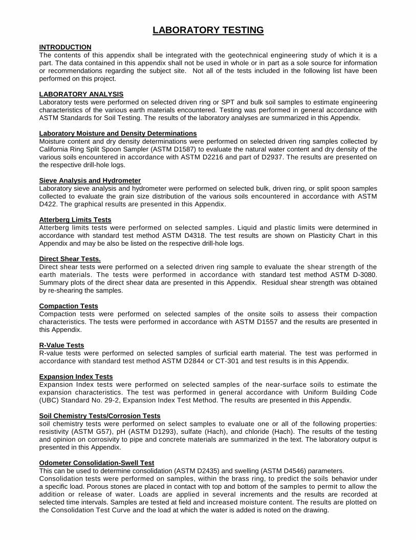
LABORATORY TESTING INTRODUCTION The contents of this appendix shall be integrated with the geotechnical engineering study of which it is a part. The data contained in this appendix shall not be used in whole or in part as a sole source for information or recommendations regarding the subject site. Not all of the tests included in the following list have been performed on this project. LABORATORY ANALYSIS Laboratory tests were performed on selected driven ring or SPT and bulk soil samples to estimate engineering characteristics of the various earth materials encountered. Testing was performed in general accordance with ASTM Standards for Soil Testing. The results of the laboratory analyses are summarized in this Appendix. Laboratory Moisture and Density Determinations Moisture content and dry density determinations were performed on selected driven ring samples collected by California Ring Split Spoon Sampler (ASTM D1587) to evaluate the natural water content and dry density of the various soils encountered in accordance with ASTM D2216 and part of D2937. The results are presented on the respective drill-hole logs. Sieve Analysis and Hydrometer Laboratory sieve analysis and hydrometer were performed on selected bulk, driven ring, or split spoon samples collected to evaluate the grain size distribution of the various soils encountered in accordance with ASTM D422. The graphical results are presented in this Appendix. Atterberg Limits Tests Atterberg limits tests were performed on selected samples. Liquid and plastic limits were determined in accordance with standard test method ASTM D4318. The test results are shown on Plasticity Chart in this Appendix and may be also be listed on the respective drill-hole logs. Direct Shear Tests. Direct shear tests were performed on a selected driven ring sample to evaluate the shear strength of the earth materials. The tests were performed in accordance with standard test method ASTM D-3080. Summary plots of the direct shear data are presented in this Appendix. Residual shear strength was obtained by re-shearing the samples. Compaction Tests Compaction tests were performed on selected samples of the onsite soils to assess their compaction characteristics. The tests were performed in accordance with ASTM D1557 and the results are presented in this Appendix. R-Value Tests R-value tests were performed on selected samples of surficial earth material. The test was performed in accordance with standard test method ASTM D2844 or CT-301 and test results is in this Appendix. Expansion Index Tests Expansion Index tests were performed on selected samples of the near-surface soils to estimate the expansion characteristics. The test was performed in general accordance with Uniform Building Code (UBC) Standard No. 29-2, Expansion Index Test Method. The results are presented in this Appendix. Soil Chemistry Tests/Corrosion Tests soil chemistry tests were performed on select samples to evaluate one or all of the following properties: resistivity (ASTM G57), pH (ASTM D1293), sulfate (Hach), and chloride (Hach). The results of the testing and opinion on corrosivity to pipe and concrete materials are summarized in the text. The laboratory output is presented in this Appendix. Odometer Consolidation-Swell Test This can be used to determine consolidation (ASTM D2435) and swelling (ASTM D4546) parameters. Consolidation tests were performed on samples, within the brass ring, to predict the soils behavior under a specific load. Porous stones are placed in contact with top and bottom of the samples to permit to allow the addition or release of water. Loads are applied in several increments and the results are recorded at selected time intervals. Samples are tested at field and increased moisture content. The results are plotted on the Consolidation Test Curve and the load at which the water is added is noted on the drawing.
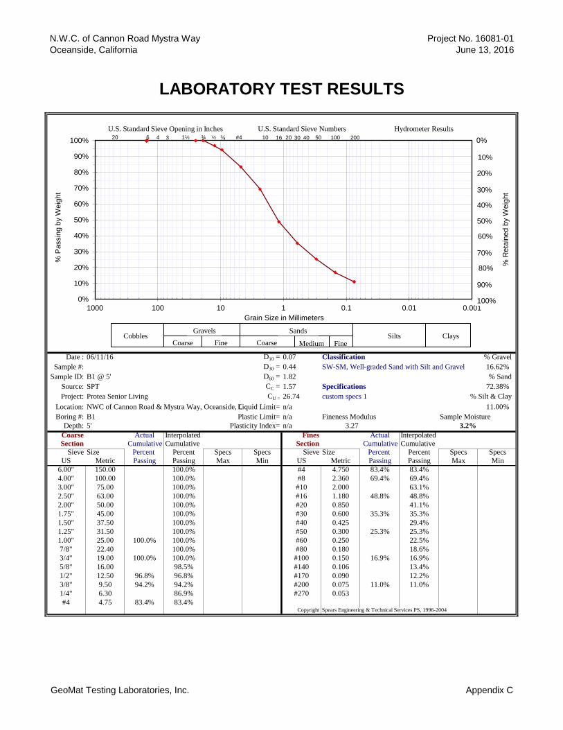
N.W.C. of Cannon Road Mystra Way
Oceanside, California
LABORATORY TEST RESULTS
Project No. 16081-01
June 13, 2016
Date : 06/11/16 D10 = 0.07 Classification % Gravel
Sample #: D30 = 0.44 SW-SM, Well-graded Sand with Silt and Gravel 16.62%
Sample ID: B1 @ 5' D60 = 1.82 % Sand
Source: SPT CC = 1.57 Specifications 72.38%
Project: Protea Senior Living CU = 26.74 custom specs 1 % Silt & Clay
Location: NWC of Cannon Road & Mystra Way, Oceanside, CALiquid Limit= n/a 11.00%
Boring #: B1 Plastic Limit= n/a Fineness Modulus Sample Moisture
Depth: 5' Plasticity Index= n/a 3.27 3.2%
Coarse Actual Interpolated Fines Actual Interpolated
Section Cumulative Cumulative Section Cumulative Cumulative
Sieve Size Percent Percent Specs Specs Sieve Size Percent Percent Specs Specs
US Metric Passing Passing Max Min US Metric Passing Passing Max Min
6.00" 150.00 100.0% #4 4.750 83.4% 83.4%
4.00" 100.00 100.0% #8 2.360 69.4% 69.4%
3.00" 75.00 100.0% #10 2.000 63.1%
2.50" 63.00 100.0% #16 1.180 48.8% 48.8%
2.00" 50.00 100.0% #20 0.850 41.1%
1.75" 45.00 100.0% #30 0.600 35.3% 35.3%
1.50" 37.50 100.0% #40 0.425 29.4%
1.25" 31.50 100.0% #50 0.300 25.3% 25.3%
1.00" 25.00 100.0% 100.0% #60 0.250 22.5%
7/8" 22.40 100.0% #80 0.180 18.6%
3/4" 19.00 100.0% 100.0% #100 0.150 16.9% 16.9%
5/8" 16.00 98.5% #140 0.106 13.4%
1/2" 12.50 96.8% 96.8% #170 0.090 12.2%
3/8" 9.50 94.2% 94.2% #200 0.075 11.0% 11.0%
1/4" 6.30 86.9% #270 0.053
#4 4.75 83.4% 83.4%Copyright Spears Engineering & Technical Services PS, 1996-2004
0%
10%
20%
30%
40%
50%
60%
70%
80%
90%
100%
0.0010.010.11101001000
% P
assin
g b
y W
eig
ht
Grain Size in Millimeters
U.S. Standard Sieve Opening in Inches U.S. Standard Sieve Numbers Hydrometer Results
Cobbles Gravels Sands
Silts Coarse Fine Coarse Medium Fine
Clays
0% #4 1½ 10 16 6 20 ¾ ⅜ 30 50 100 200 3 4 40 20 ½
20%
50%
60%
70%
10%
80%
30%
40%
90%
100%
% R
eta
ined b
y W
eig
ht
GeoMat Testing Laboratories, Inc. Appendix C
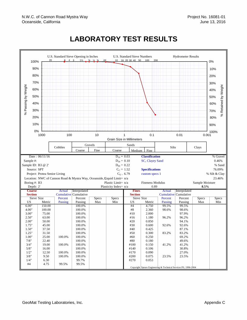
N.W.C. of Cannon Road Mystra Way
Oceanside, California
LABORATORY TEST RESULTS
Project No. 16081-01
June 13, 2016
Date : 06/11/16 D10 = 0.03 Classification % Gravel
Sample #: D30 = 0.10 SC, Clayey Sand 0.46%
Sample ID: B3 @ 2' D60 = 0.22 % Sand
Source: SPT CC = 1.52 Specifications 76.09%
Project: Protea Senior Living CU = 6.79 custom specs 1 % Silt & Clay
Location: NWC of Cannon Road & Mystra Way, Oceanside, CALiquid Limit= n/a 23.46%
Boring #: B3 Plastic Limit= n/a Fineness Modulus Sample Moisture
Depth: 2' Plasticity Index= n/a 0.89 8.5%
Coarse Actual Interpolated Fines Actual Interpolated
Section Cumulative Cumulative Section Cumulative Cumulative
Sieve Size Percent Percent Specs Specs Sieve Size Percent Percent Specs Specs
US Metric Passing Passing Max Min US Metric Passing Passing Max Min
6.00" 150.00 100.0% #4 4.750 99.5% 99.5%
4.00" 100.00 100.0% #8 2.360 98.6% 98.6%
3.00" 75.00 100.0% #10 2.000 97.9%
2.50" 63.00 100.0% #16 1.180 96.2% 96.2%
2.00" 50.00 100.0% #20 0.850 94.1%
1.75" 45.00 100.0% #30 0.600 92.6% 92.6%
1.50" 37.50 100.0% #40 0.425 87.1%
1.25" 31.50 100.0% #50 0.300 83.2% 83.2%
1.00" 25.00 100.0% 100.0% #60 0.250 69.2%
7/8" 22.40 100.0% #80 0.180 49.6%
3/4" 19.00 100.0% 100.0% #100 0.150 41.2% 41.2%
5/8" 16.00 100.0% #140 0.106 30.8%
1/2" 12.50 100.0% 100.0% #170 0.090 27.0%
3/8" 9.50 100.0% 100.0% #200 0.075 23.5% 23.5%
1/4" 6.30 99.7% #270 0.053
#4 4.75 99.5% 99.5%Copyright Spears Engineering & Technical Services PS, 1996-2004
0%
10%
20%
30%
40%
50%
60%
70%
80%
90%
100%
0.0010.010.11101001000
% P
assin
g b
y W
eig
ht
Grain Size in Millimeters
U.S. Standard Sieve Opening in Inches U.S. Standard Sieve Numbers Hydrometer Results
Cobbles Gravels Sands
Silts Coarse Fine Coarse Medium Fine
Clays
0% #4 1½ 10 16 6 20 ¾ ⅜ 30 50 100 200 3 4 40 20 ½
20%
50%
60%
70%
10%
80%
30%
40%
90%
100%
% R
eta
ined b
y W
eig
ht
GeoMat Testing Laboratories, Inc. Appendix C
N.W.C. of Cannon Road Mystra Way
Oceanside, California
LABORATORY TEST RESULTS
Project No. 16081-01
June 13, 2016
Date : 06/11/16 D10 = 0.01 Classification % Gravel
Sample #: D30 = 0.04 #N/A 0.16%
Sample ID: B4 @ 7' D60 = 0.13 % Sand
Source: Bulk CC = 1.01 Specifications 47.28%
Project: Protea Senior Living CU = 8.94 custom specs 1 % Silt & Clay
Location: NWC of Cannon Road & Mystra Way, Oceanside, CALiquid Limit= n/a 52.55%
Boring #: B4 Plastic Limit= n/a Fineness Modulus Sample Moisture
Depth: 7' Plasticity Index= n/a 0.87 10.1%
Coarse Actual Interpolated Fines Actual Interpolated
Section Cumulative Cumulative Section Cumulative Cumulative
Sieve Size Percent Percent Specs Specs Sieve Size Percent Percent Specs Specs
US Metric Passing Passing Max Min US Metric Passing Passing Max Min
6.00" 150.00 100.0% #4 4.750 99.8% 99.8%
4.00" 100.00 100.0% #8 2.360 96.9% 96.9%
3.00" 75.00 100.0% #10 2.000 95.2%
2.50" 63.00 100.0% #16 1.180 91.4% 91.4%
2.00" 50.00 100.0% #20 0.850 87.7%
1.75" 45.00 100.0% #30 0.600 84.9% 84.9%
1.50" 37.50 100.0% #40 0.425 80.1%
1.25" 31.50 100.0% #50 0.300 76.7% 76.7%
1.00" 25.00 100.0% 100.0% #60 0.250 72.2%
7/8" 22.40 100.0% #80 0.180 65.9%
3/4" 19.00 100.0% 100.0% #100 0.150 63.2% 63.2%
5/8" 16.00 100.0% #140 0.106 56.9%
1/2" 12.50 100.0% 100.0% #170 0.090 54.7%
3/8" 9.50 100.0% 100.0% #200 0.075 52.6% 52.6%
1/4" 6.30 99.9% #270 0.053
#4 4.75 99.8% 99.8%Copyright Spears Engineering & Technical Services PS, 1996-2004
0%
10%
20%
30%
40%
50%
60%
70%
80%
90%
100%
0.0010.010.11101001000
% P
assin
g b
y W
eig
ht
Grain Size in Millimeters
U.S. Standard Sieve Opening in Inches U.S. Standard Sieve Numbers Hydrometer Results
Cobbles Gravels Sands
Silts Coarse Fine Coarse Medium Fine
Clays
0% #4 1½ 10 16 6 20 ¾ ⅜ 30 50 100 200 3 4 40 20 ½
20%
50%
60%
70%
10%
80%
30%
40%
90%
100%
% R
eta
ined b
y W
eig
ht
GeoMat Testing Laboratories, Inc. Appendix C
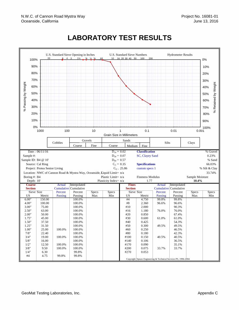
N.W.C. of Cannon Road Mystra Way
Oceanside, California
LABORATORY TEST RESULTS
Project No. 16081-01
June 13, 2016
Date : 06/11/16 D10 = 0.02 Classification % Gravel
Sample #: D30 = 0.07 SC, Clayey Sand 0.23%
Sample ID: B4 @ 10' D60 = 0.57 % Sand
Source: Cal Ring CC = 0.35 Specifications 66.03%
Project: Protea Senior Living CU = 25.86 custom specs 1 % Silt & Clay
Location: NWC of Cannon Road & Mystra Way, Oceanside, CALiquid Limit= n/a 33.74%
Boring #: B4 Plastic Limit= n/a Fineness Modulus Sample Moisture
Depth: 10' Plasticity Index= n/a 1.77 10.4%
Coarse Actual Interpolated Fines Actual Interpolated
Section Cumulative Cumulative Section Cumulative Cumulative
Sieve Size Percent Percent Specs Specs Sieve Size Percent Percent Specs Specs
US Metric Passing Passing Max Min US Metric Passing Passing Max Min
6.00" 150.00 100.0% #4 4.750 99.8% 99.8%
4.00" 100.00 100.0% #8 2.360 96.6% 96.6%
3.00" 75.00 100.0% #10 2.000 90.3%
2.50" 63.00 100.0% #16 1.180 76.0% 76.0%
2.00" 50.00 100.0% #20 0.850 67.4%
1.75" 45.00 100.0% #30 0.600 61.0% 61.0%
1.50" 37.50 100.0% #40 0.425 54.3%
1.25" 31.50 100.0% #50 0.300 49.5% 49.5%
1.00" 25.00 100.0% 100.0% #60 0.250 46.5%
7/8" 22.40 100.0% #80 0.180 42.3%
3/4" 19.00 100.0% 100.0% #100 0.150 40.5% 40.5%
5/8" 16.00 100.0% #140 0.106 36.5%
1/2" 12.50 100.0% 100.0% #170 0.090 35.1%
3/8" 9.50 100.0% 100.0% #200 0.075 33.7% 33.7%
1/4" 6.30 99.8% #270 0.053
#4 4.75 99.8% 99.8%Copyright Spears Engineering & Technical Services PS, 1996-2004
0%
10%
20%
30%
40%
50%
60%
70%
80%
90%
100%
0.0010.010.11101001000
% P
assin
g b
y W
eig
ht
Grain Size in Millimeters
U.S. Standard Sieve Opening in Inches U.S. Standard Sieve Numbers Hydrometer Results
Cobbles Gravels Sands
Silts Coarse Fine Coarse Medium Fine
Clays
0% #4 1½ 10 16 6 20 ¾ ⅜ 30 50 100 200 3 4 40 20 ½
20%
50%
60%
70%
10%
80%
30%
40%
90%
100%
% R
eta
ined b
y W
eig
ht
GeoMat Testing Laboratories, Inc. Appendix C
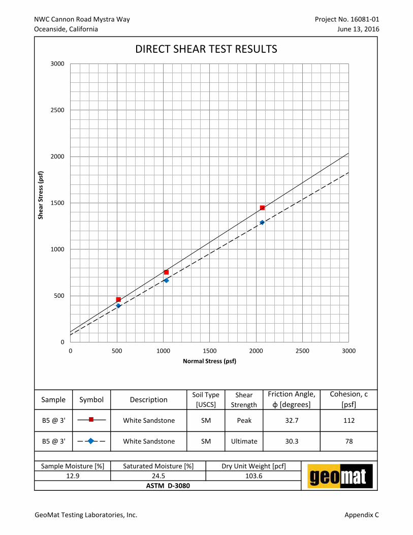
NWC Cannon Road Mystra Way
Oceanside, California
Project No. 16081-01
June 13, 2016
32.7 112
30.3 78B5 @ 3' White Sandstone SM Ultimate
B5 @ 3' SM PeakWhite Sandstone
DIRECT SHEAR TEST RESULTS
Sample Symbol DescriptionSoil Type
[USCS]
Shear
Strength
Friction Angle,
φ [degrees]
Cohesion, c
[psf]
ASTM D-3080
Sample Moisture [%] Saturated Moisture [%] Dry Unit Weight [pcf]
12.9 24.5 103.6
0
500
1000
1500
2000
2500
3000
0 500 1000 1500 2000 2500 3000
She
ar S
tre
ss (
psf
)
Normal Stress (psf)
GeoMat Testing Laboratories, Inc. Appendix C
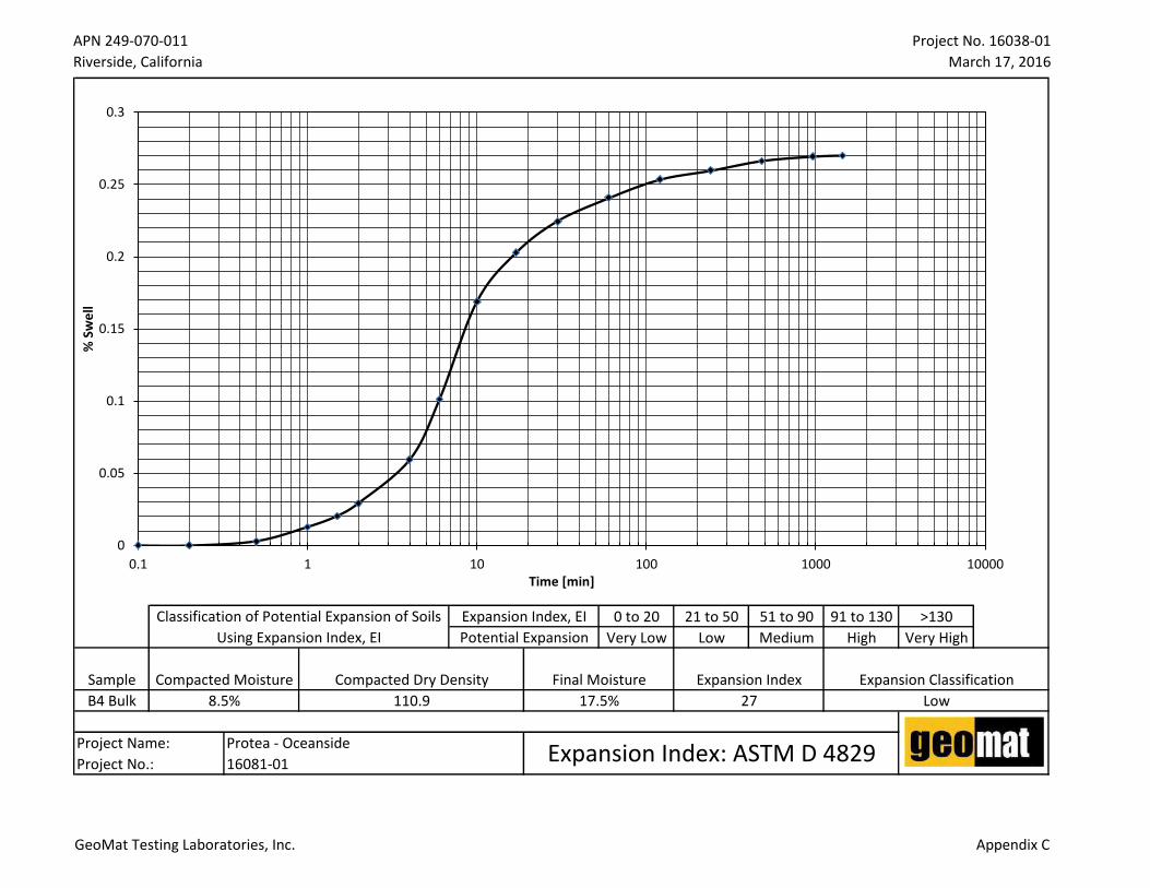
APN 249-070-011
Riverside, California
Project No. 16038-01
March 17, 2016
0 to 20 21 to 50 51 to 90 91 to 130 >130
Very Low Low Medium High Very High
B4 Bulk
Project Name:
Project No.:
Sample Compacted Moisture Compacted Dry Density Final Moisture Expansion Index
Classification of Potential Expansion of Soils
Using Expansion Index, EI
Expansion Index, EI
Potential Expansion
Protea - Oceanside
16081-01 Expansion Index: ASTM D 4829
Expansion Classification
8.5% 110.9 17.5% 27 Low
0
0.05
0.1
0.15
0.2
0.25
0.3
0.1 1 10 100 1000 10000
% S
we
ll
Time [min]
GeoMat Testing Laboratories, Inc. Appendix C

9980 Indiana Avenue ● Suite 14 ● Riverside ● California ● 92503 ● Phone (951) 688-5400 ● Fax (951) 688-5200 www.geomatlabs.com, contact: e-mail: [email protected]
GeoMat Testing Laboratories, Inc.
Soil Engineering, Environmental Engineering, Materials Testing, Geology
SOLUBLE SULFATE AND CHLORIDE TEST RESULTS Project Name Protea Senior Living Test Date 6/13/2016
Project No. 16081-01 Date Sampled 6/11/2016
Project Location NWC Cannon Rd & Mystra Way, Oceanside, CA Sampled By AM
Location in Structure B4 Bulk Sample Type Bulk
Sampled Classification SC Tested By AM
TESTING INFORMATION Sample weight before drying --
Sample weight after drying --
Sample Weight Passing No. 10 Sieve 100 grams
Moisture --
Location Mixing Ratio
Dilution Factor
Sulfate Reading
(ppm)
Sulfate Content
Chloride Reading
(ppm)
Chloride Content
pH
(ppm) (%) (ppm) (%)
B4 3 2 75 450 0.045
Average Average Average
ACI 318-05 Table 4.3.1 Requirements for Concrete Exposed to Sulfate-Containing Solutions
Sulfate Exposure
Water-Soluble Sulfate (SO4)
In Soil, % by Mass
Sulfate (SO4) In Water
ppm Cement Type
Maximum w/cm
by Mass
Minimum Design Compressive Strength
fc, MPa (psi)
Negligible < 0.10 < 150 No Special Type -- --
Moderate (see water)
0.10 to 0.20 150 to 1500
II IP(MS), IS(MS),
P(MS), I(PM)(MS), I(SM)(MS)
0.50 28 (4000)
Severe 0.20 to 2.00 1500 to 10,000
V 0.45 31 (4500)
Very Severe > 2.00 >10,000 V + pozz 0.45 31 (4500)
Caltrans classifies a site as corrosive to structural concrete as an area where soil and/or water contains >500pp chloride, >2000ppm sulfate, or has a pH <5.5. A minimum resistivity of less than 1000 ohm-cm indicates the potential for corrosive environment requiring testing for the above criteria. The 2007 CBC Section 1904A references ACI 318 for material selection and mix design for reinforced concrete dependant on the onsite corrosion potential, soluble chloride content, and soluble sulfate content in soil
Comments:Sec 4.3 of ACI 318 (2005) Soil environment is detrimental to concrete if it has soluble sulfate
>1000ppm and/or pH<5.5. Soil environment is corrosive to reinforcement and steel pipes if Chloride ion
>500ppm or pH <4.0.
Signature Date
Print Name Title
The information in this form is not intended for corrosion engineering design. If corrosion is critical, a corrosion specialist should be contacted to provide further recommendations.

Appendix D
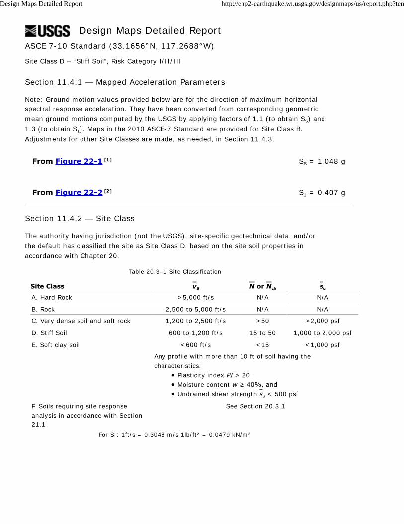
Design Maps Detailed Report
From Figure 22-1 [1]
From Figure 22-2 [2]
ASCE 7-10 Standard (33.1656°N, 117.2688°W)
Site Class D – “Stiff Soil”, Risk Category I/II/III
Section 11.4.1 — Mapped Acceleration Parameters
Note: Ground motion values provided below are for the direction of maximum horizontal
spectral response acceleration. They have been converted from corresponding geometric
mean ground motions computed by the USGS by applying factors of 1.1 (to obtain SS) and
1.3 (to obtain S1). Maps in the 2010 ASCE-7 Standard are provided for Site Class B.
Adjustments for other Site Classes are made, as needed, in Section 11.4.3.
SS = 1.048 g
S1 = 0.407 g
Section 11.4.2 — Site Class
The authority having jurisdiction (not the USGS), site-specific geotechnical data, and/or
the default has classified the site as Site Class D, based on the site soil properties in
accordance with Chapter 20.
Table 20.3–1 Site Classification
Site Class vS N or Nch su
A. Hard Rock >5,000 ft/s N/A N/A
B. Rock 2,500 to 5,000 ft/s N/A N/A
C. Very dense soil and soft rock 1,200 to 2,500 ft/s >50 >2,000 psf
D. Stiff Soil 600 to 1,200 ft/s 15 to 50 1,000 to 2,000 psf
E. Soft clay soil <600 ft/s <15 <1,000 psf
Any profile with more than 10 ft of soil having the
characteristics:
Plasticity index PI > 20,
Moisture content w ≥ 40%, and
Undrained shear strength su < 500 psf
F. Soils requiring site response
analysis in accordance with Section
21.1
See Section 20.3.1
For SI: 1ft/s = 0.3048 m/s 1lb/ft² = 0.0479 kN/m²
Design Maps Detailed Report http://ehp2-earthquake.wr.usgs.gov/designmaps/us/report.php?template...
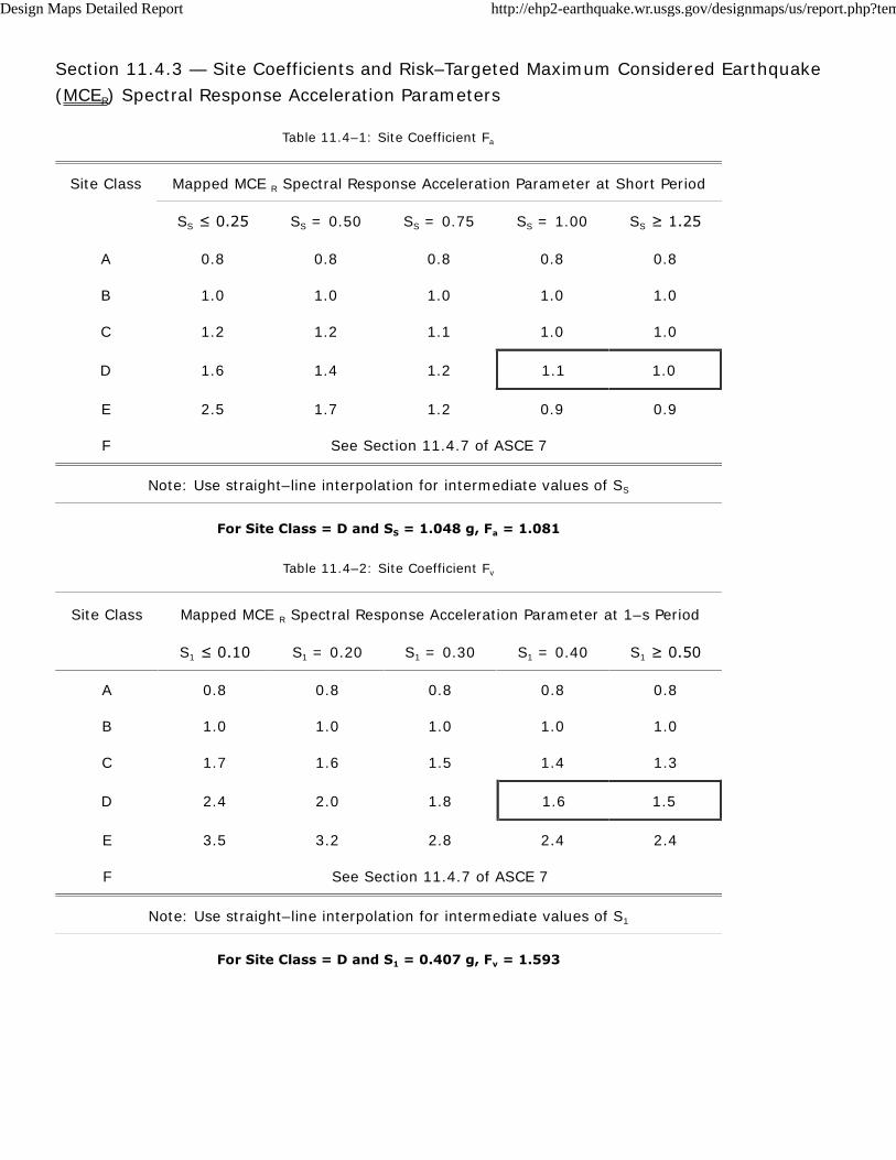
Section 11.4.3 — Site Coefficients and Risk–Targeted Maximum Considered Earthquake
(MCER) Spectral Response Acceleration Parameters
Table 11.4–1: Site Coefficient Fa
Site Class Mapped MCE R Spectral Response Acceleration Parameter at Short Period
SS ≤ 0.25 SS = 0.50 SS = 0.75 SS = 1.00 SS ≥ 1.25
A 0.8 0.8 0.8 0.8 0.8
B 1.0 1.0 1.0 1.0 1.0
C 1.2 1.2 1.1 1.0 1.0
D 1.6 1.4 1.2 1.1 1.0
E 2.5 1.7 1.2 0.9 0.9
F See Section 11.4.7 of ASCE 7
Note: Use straight–line interpolation for intermediate values of SS
For Site Class = D and SS = 1.048 g, Fa = 1.081
Table 11.4–2: Site Coefficient Fv
Site Class Mapped MCE R Spectral Response Acceleration Parameter at 1–s Period
S1 ≤ 0.10 S1 = 0.20 S1 = 0.30 S1 = 0.40 S1 ≥ 0.50
A 0.8 0.8 0.8 0.8 0.8
B 1.0 1.0 1.0 1.0 1.0
C 1.7 1.6 1.5 1.4 1.3
D 2.4 2.0 1.8 1.6 1.5
E 3.5 3.2 2.8 2.4 2.4
F See Section 11.4.7 of ASCE 7
Note: Use straight–line interpolation for intermediate values of S1
For Site Class = D and S1 = 0.407 g, Fv = 1.593
Design Maps Detailed Report http://ehp2-earthquake.wr.usgs.gov/designmaps/us/report.php?template...
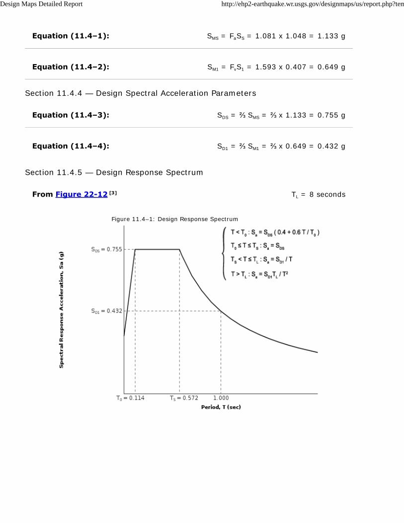
Equation (11.4–1):
Equation (11.4–2):
Equation (11.4–3):
Equation (11.4–4):
From Figure 22-12 [3]
SMS = FaSS = 1.081 x 1.048 = 1.133 g
SM1 = FvS1 = 1.593 x 0.407 = 0.649 g
Section 11.4.4 — Design Spectral Acceleration Parameters
SDS = ⅔ SMS = ⅔ x 1.133 = 0.755 g
SD1 = ⅔ SM1 = ⅔ x 0.649 = 0.432 g
Section 11.4.5 — Design Response Spectrum
TL = 8 seconds
Figure 11.4–1: Design Response Spectrum
Design Maps Detailed Report http://ehp2-earthquake.wr.usgs.gov/designmaps/us/report.php?template...
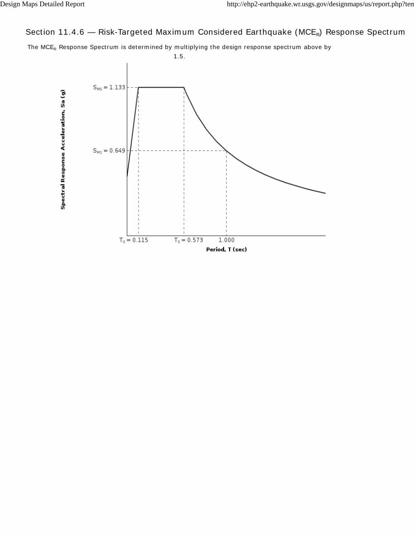
Section 11.4.6 — Risk-Targeted Maximum Considered Earthquake (MCER) Response Spectrum
The MCER Response Spectrum is determined by multiplying the design response spectrum above by
1.5.
Design Maps Detailed Report http://ehp2-earthquake.wr.usgs.gov/designmaps/us/report.php?template...
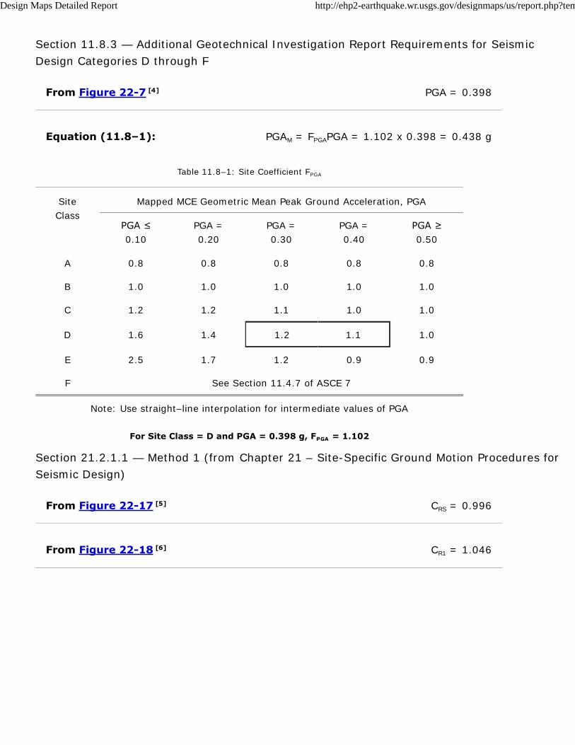
From Figure 22-7 [4]
Equation (11.8–1):
From Figure 22-17 [5]
From Figure 22-18 [6]
Section 11.8.3 — Additional Geotechnical Investigation Report Requirements for Seismic
Design Categories D through F
PGA = 0.398
PGAM = FPGAPGA = 1.102 x 0.398 = 0.438 g
Table 11.8–1: Site Coefficient FPGA
Site
Class
Mapped MCE Geometric Mean Peak Ground Acceleration, PGA
PGA ≤
0.10
PGA =
0.20
PGA =
0.30
PGA =
0.40
PGA ≥
0.50
A 0.8 0.8 0.8 0.8 0.8
B 1.0 1.0 1.0 1.0 1.0
C 1.2 1.2 1.1 1.0 1.0
D 1.6 1.4 1.2 1.1 1.0
E 2.5 1.7 1.2 0.9 0.9
F See Section 11.4.7 of ASCE 7
Note: Use straight–line interpolation for intermediate values of PGA
For Site Class = D and PGA = 0.398 g, FPGA = 1.102
Section 21.2.1.1 — Method 1 (from Chapter 21 – Site-Specific Ground Motion Procedures for
Seismic Design)
CRS = 0.996
CR1 = 1.046
Design Maps Detailed Report http://ehp2-earthquake.wr.usgs.gov/designmaps/us/report.php?template...
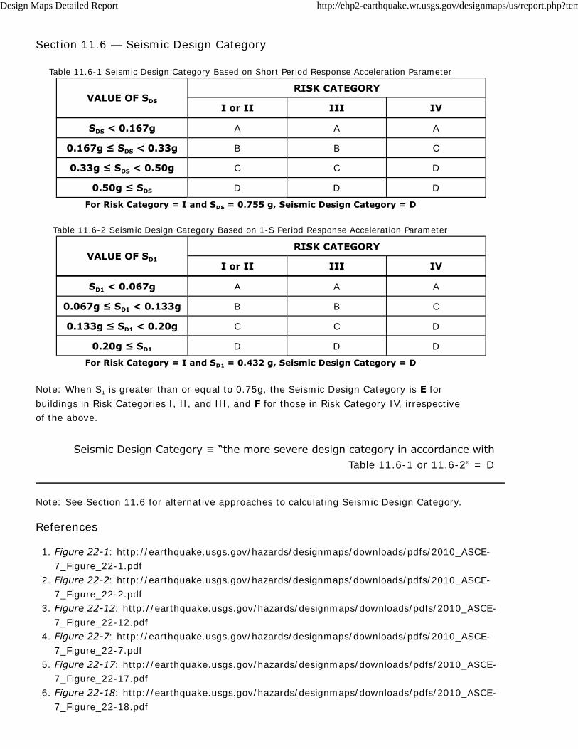
Section 11.6 — Seismic Design Category
Table 11.6-1 Seismic Design Category Based on Short Period Response Acceleration Parameter
VALUE OF SDS
RISK CATEGORY
I or II III IV
SDS < 0.167g A A A
0.167g ≤ SDS < 0.33g B B C
0.33g ≤ SDS < 0.50g C C D
0.50g ≤ SDS D D D
For Risk Category = I and SDS = 0.755 g, Seismic Design Category = D
Table 11.6-2 Seismic Design Category Based on 1-S Period Response Acceleration Parameter
VALUE OF SD1
RISK CATEGORY
I or II III IV
SD1 < 0.067g A A A
0.067g ≤ SD1 < 0.133g B B C
0.133g ≤ SD1 < 0.20g C C D
0.20g ≤ SD1 D D D
For Risk Category = I and SD1 = 0.432 g, Seismic Design Category = D
Note: When S1 is greater than or equal to 0.75g, the Seismic Design Category is E for
buildings in Risk Categories I, II, and III, and F for those in Risk Category IV, irrespective
of the above.
Seismic Design Category ≡ “the more severe design category in accordance with
Table 11.6-1 or 11.6-2” = D
Note: See Section 11.6 for alternative approaches to calculating Seismic Design Category.
References
Figure 22-1: http://earthquake.usgs.gov/hazards/designmaps/downloads/pdfs/2010_ASCE-
7_Figure_22-1.pdf
1.
Figure 22-2: http://earthquake.usgs.gov/hazards/designmaps/downloads/pdfs/2010_ASCE-
7_Figure_22-2.pdf
2.
Figure 22-12: http://earthquake.usgs.gov/hazards/designmaps/downloads/pdfs/2010_ASCE-
7_Figure_22-12.pdf
3.
Figure 22-7: http://earthquake.usgs.gov/hazards/designmaps/downloads/pdfs/2010_ASCE-
7_Figure_22-7.pdf
4.
Figure 22-17: http://earthquake.usgs.gov/hazards/designmaps/downloads/pdfs/2010_ASCE-
7_Figure_22-17.pdf
5.
Figure 22-18: http://earthquake.usgs.gov/hazards/designmaps/downloads/pdfs/2010_ASCE-
7_Figure_22-18.pdf
6.
Design Maps Detailed Report http://ehp2-earthquake.wr.usgs.gov/designmaps/us/report.php?template...

Appendix E
General Earthwork and Grading Specifications
GeoMat Testing Laboratories, Inc. i
TABLE OF CONTENT Page
GENERAL ........................................................................................................................................... I
DEFINITION OF TERMS .................................................................................................................... I
OBLIGATIONS OF PARTIES ............................................................................................................. III
SITE PREPARATION ......................................................................................................................... IV
SITE PROTECTION ........................................................................................................................... IV
EXCAVATIONS .................................................................................................................................. V
Unsuitable Materials ........................................................................................................................... V
Cut Slopes........................................................................................................................................... V
Pad Areas ........................................................................................................................................... V
COMPACTED FILL ............................................................................................................................. VI
Placement ........................................................................................................................................... VI
Moisture .............................................................................................................................................. VII
Fill Material .......................................................................................................................................... VII
Fill Slopes ............................................................................................................................................ VIII
Off-Site Fill .......................................................................................................................................... VIII
DRAINAGE ......................................................................................................................................... IX
STAKING ............................................................................................................................................ IX
SLOPE MAINTENANCE ..................................................................................................................... IX
Landscape Plants ............................................................................................................................... IX
Irrigation .............................................................................................................................................. IX
Maintenance........................................................................................................................................ IX
Repairs ................................................................................................................................................ X
TRENCH BACKFILL ........................................................................................................................... X
STATUS OF GRADING ...................................................................................................................... X
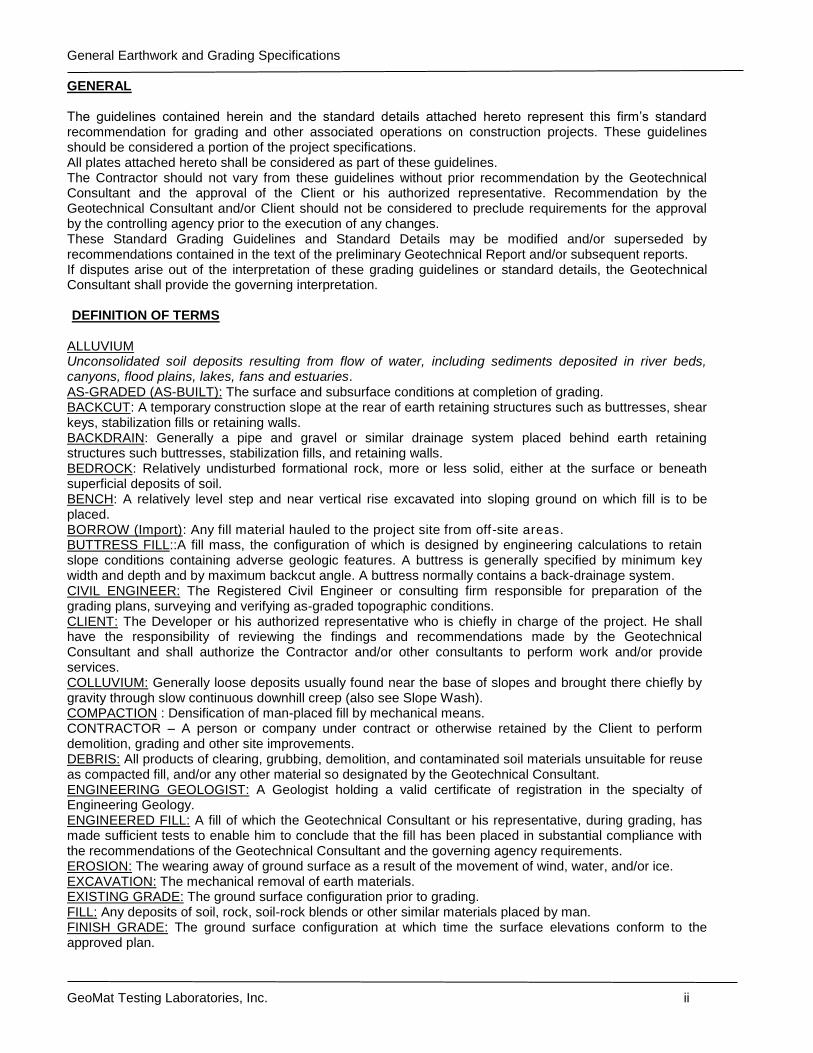
General Earthwork and Grading Specifications
GeoMat Testing Laboratories, Inc. ii
GENERAL The guidelines contained herein and the standard details attached hereto represent this firm’s standard recommendation for grading and other associated operations on construction projects. These guidelines should be considered a portion of the project specifications. All plates attached hereto shall be considered as part of these guidelines. The Contractor should not vary from these guidelines without prior recommendation by the Geotechnical Consultant and the approval of the Client or his authorized representative. Recommendation by the Geotechnical Consultant and/or Client should not be considered to preclude requirements for the approval by the controlling agency prior to the execution of any changes. These Standard Grading Guidelines and Standard Details may be modified and/or superseded by recommendations contained in the text of the preliminary Geotechnical Report and/or subsequent reports. If disputes arise out of the interpretation of these grading guidelines or standard details, the Geotechnical Consultant shall provide the governing interpretation. DEFINITION OF TERMS
ALLUVIUM Unconsolidated soil deposits resulting from flow of water, including sediments deposited in river beds, canyons, flood plains, lakes, fans and estuaries. AS-GRADED (AS-BUILT): The surface and subsurface conditions at completion of grading. BACKCUT: A temporary construction slope at the rear of earth retaining structures such as buttresses, shear keys, stabilization fills or retaining walls. BACKDRAIN: Generally a pipe and gravel or similar drainage system placed behind earth retaining structures such buttresses, stabilization fills, and retaining walls. BEDROCK: Relatively undisturbed formational rock, more or less solid, either at the surface or beneath superficial deposits of soil. BENCH: A relatively level step and near vertical rise excavated into sloping ground on which fill is to be placed. BORROW (Import): Any fill material hauled to the project site from off-site areas. BUTTRESS FILL::A fill mass, the configuration of which is designed by engineering calculations to retain slope conditions containing adverse geologic features. A buttress is generally specified by minimum key width and depth and by maximum backcut angle. A buttress normally contains a back-drainage system. CIVIL ENGINEER: The Registered Civil Engineer or consulting firm responsible for preparation of the grading plans, surveying and verifying as-graded topographic conditions. CLIENT: The Developer or his authorized representative who is chiefly in charge of the project. He shall have the responsibility of reviewing the findings and recommendations made by the Geotechnical Consultant and shall authorize the Contractor and/or other consultants to perform work and/or provide services. COLLUVIUM: Generally loose deposits usually found near the base of slopes and brought there chiefly by gravity through slow continuous downhill creep (also see Slope Wash). COMPACTION : Densification of man-placed fill by mechanical means. CONTRACTOR – A person or company under contract or otherwise retained by the Client to perform demolition, grading and other site improvements. DEBRIS: All products of clearing, grubbing, demolition, and contaminated soil materials unsuitable for reuse as compacted fill, and/or any other material so designated by the Geotechnical Consultant. ENGINEERING GEOLOGIST: A Geologist holding a valid certificate of registration in the specialty of Engineering Geology. ENGINEERED FILL: A fill of which the Geotechnical Consultant or his representative, during grading, has made sufficient tests to enable him to conclude that the fill has been placed in substantial compliance with the recommendations of the Geotechnical Consultant and the governing agency requirements. EROSION: The wearing away of ground surface as a result of the movement of wind, water, and/or ice. EXCAVATION: The mechanical removal of earth materials. EXISTING GRADE: The ground surface configuration prior to grading. FILL: Any deposits of soil, rock, soil-rock blends or other similar materials placed by man. FINISH GRADE: The ground surface configuration at which time the surface elevations conform to the approved plan.
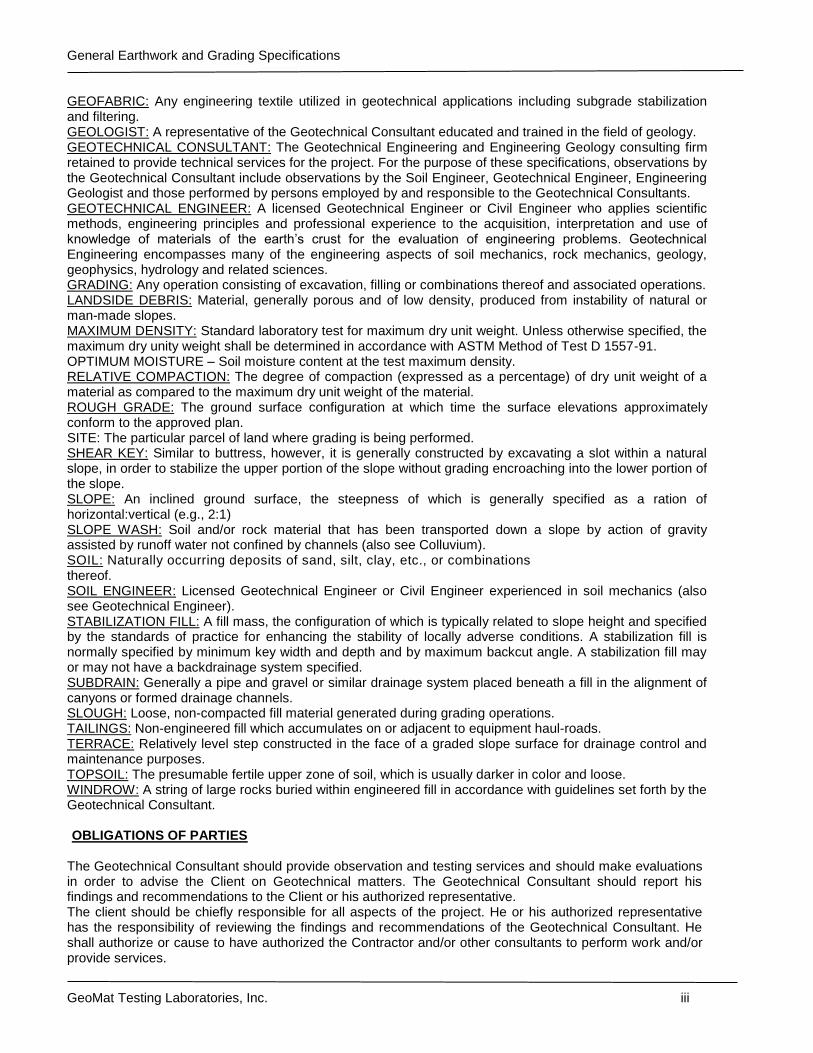
General Earthwork and Grading Specifications
GeoMat Testing Laboratories, Inc. iii
GEOFABRIC: Any engineering textile utilized in geotechnical applications including subgrade stabilization and filtering. GEOLOGIST: A representative of the Geotechnical Consultant educated and trained in the field of geology. GEOTECHNICAL CONSULTANT: The Geotechnical Engineering and Engineering Geology consulting firm retained to provide technical services for the project. For the purpose of these specifications, observations by the Geotechnical Consultant include observations by the Soil Engineer, Geotechnical Engineer, Engineering Geologist and those performed by persons employed by and responsible to the Geotechnical Consultants. GEOTECHNICAL ENGINEER: A licensed Geotechnical Engineer or Civil Engineer who applies scientific methods, engineering principles and professional experience to the acquisition, interpretation and use of knowledge of materials of the earth’s crust for the evaluation of engineering problems. Geotechnical Engineering encompasses many of the engineering aspects of soil mechanics, rock mechanics, geology, geophysics, hydrology and related sciences. GRADING: Any operation consisting of excavation, filling or combinations thereof and associated operations. LANDSIDE DEBRIS: Material, generally porous and of low density, produced from instability of natural or man-made slopes. MAXIMUM DENSITY: Standard laboratory test for maximum dry unit weight. Unless otherwise specified, the maximum dry unity weight shall be determined in accordance with ASTM Method of Test D 1557-91. OPTIMUM MOISTURE – Soil moisture content at the test maximum density. RELATIVE COMPACTION: The degree of compaction (expressed as a percentage) of dry unit weight of a material as compared to the maximum dry unit weight of the material. ROUGH GRADE: The ground surface configuration at which time the surface elevations approximately conform to the approved plan. SITE: The particular parcel of land where grading is being performed. SHEAR KEY: Similar to buttress, however, it is generally constructed by excavating a slot within a natural slope, in order to stabilize the upper portion of the slope without grading encroaching into the lower portion of the slope. SLOPE: An inclined ground surface, the steepness of which is generally specified as a ration of horizontal:vertical (e.g., 2:1) SLOPE WASH: Soil and/or rock material that has been transported down a slope by action of gravity assisted by runoff water not confined by channels (also see Colluvium). SOIL: Naturally occurring deposits of sand, silt, clay, etc., or combinations thereof. SOIL ENGINEER: Licensed Geotechnical Engineer or Civil Engineer experienced in soil mechanics (also see Geotechnical Engineer). STABILIZATION FILL: A fill mass, the configuration of which is typically related to slope height and specified by the standards of practice for enhancing the stability of locally adverse conditions. A stabilization fill is normally specified by minimum key width and depth and by maximum backcut angle. A stabilization fill may or may not have a backdrainage system specified. SUBDRAIN: Generally a pipe and gravel or similar drainage system placed beneath a fill in the alignment of canyons or formed drainage channels. SLOUGH: Loose, non-compacted fill material generated during grading operations. TAILINGS: Non-engineered fill which accumulates on or adjacent to equipment haul-roads. TERRACE: Relatively level step constructed in the face of a graded slope surface for drainage control and maintenance purposes. TOPSOIL: The presumable fertile upper zone of soil, which is usually darker in color and loose. WINDROW: A string of large rocks buried within engineered fill in accordance with guidelines set forth by the Geotechnical Consultant. OBLIGATIONS OF PARTIES
The Geotechnical Consultant should provide observation and testing services and should make evaluations in order to advise the Client on Geotechnical matters. The Geotechnical Consultant should report his findings and recommendations to the Client or his authorized representative. The client should be chiefly responsible for all aspects of the project. He or his authorized representative has the responsibility of reviewing the findings and recommendations of the Geotechnical Consultant. He shall authorize or cause to have authorized the Contractor and/or other consultants to perform work and/or provide services.
General Earthwork and Grading Specifications
GeoMat Testing Laboratories, Inc. iv
During grading the Client or his authorized representative should remain on-site or should remain reasonably accessible to all concerned parties in order to make decisions necessary to maintain the flow of the project. The Contractor should be responsible for the safety of the project and satisfactory completion of all grading and other associated operations on construction projects, including but not limited to, earthwork in accordance with the project plans, specifications and controlling agency requirements. During grading, the Contractor or his authorized representative should remain on-site. Overnight and on days off, the Contractor should remain accessible. SITE PREPARATION
The Client, prior to any site preparation or grading, should arrange and attend a meeting among the Grading Contractor, the Design Engineer, the Geotechnical Consultant, representatives of the appropriate governing authorities as well as any other concerned parties. All parties should be given at least 48 hours notice. Clearing and grubbing should consist of the removal of vegetation such as brush, grass, woods, stumps, trees, roots of trees and otherwise deleterious natural materials from the areas to be graded. Clearing and grubbing should extend to the outside of all proposed excavation and fill areas. Demolition should include removal of buildings, structures, foundations, reservoirs, utilities (including underground pipelines, septic tanks, leach fields, seepage pits, cisterns, mining shafts, tunnels, etc.) and man-made surface and subsurface improvements from the areas to be graded. Demolition of utilities should include proper capping and/or re-routing pipelines at the project perimeter and cutoff and capping of wells in accordance with the requirements of the governing authorities and the recommendations of the Geotechnical Consultant at the time of the demolition. Trees, plants or man-made improvements not planned to be removed or demolished should be protected by the Contractor from damage or injury. Debris generated during clearing, grubbing and/or demolition operations should be wasted from areas to be graded and disposed off-site. Clearing, grubbing and demolition operations should be performed under the observation of the Geotechnical Consultant. The Client or Contractor should obtain the required approvals for the controlling authorities for the project prior, during and/or after demolition, site preparation and removals, etc. The appropriate approvals should be obtained prior to proceeding with grading operations. SITE PROTECTION
Protection of the site during the period of grading should be the responsibility of the Contractor. Unless other provisions are made in writing and agreed upon among the concerned parties, completion of a portion of the project should not be considered to preclude that portion or adjacent areas from the requirements for site protection until such time as the entire project is complete as identified by the Geotechnical Consultant, the Client and the regulating agencies. The Contractor should be responsible for the stability of all temporary excavations. Recommendations by the Geotechnical Consultant pertaining to temporary excavations (e.g., backcuts) are made in consideration of stability of the completed project and therefore, should not be considered to preclude the responsibilities of the Contractor. Recommendations by the Geotechnical Consultant should not be considered to preclude more restrictive requirements by the regulating agencies. Precautions should be taken during the performance of site clearing, excavations and grading to protect the work site from flooding, ponding, or inundation by poor or improper surface drainage. Temporary provisions should be made during the rainy season to adequately direct surface drainage away from and off the work site. Where low areas can not be avoided, pumps should be kept on hand to continually remove water during periods of rainfall. During periods of rainfall, plastic sheeting should be kept reasonably accessible to prevent unprotected slopes from becoming saturated. Where necessary during periods of rainfall, the Contractor should install check-dams de-silting basins, rip-rap, sandbags or other devices or methods necessary to control erosion and provide safe conditions. During periods of rainfall, the Geotechnical Consultant should be kept informed by the Contractor as to the nature of remedial or preventative work being performed (e.g., pumping, placement of sandbags or plastic sheeting, other labor, dozing, etc.).
General Earthwork and Grading Specifications
GeoMat Testing Laboratories, Inc. v
Following periods of rainfall, the Contractor should contact the Geotechnical Consultant and arrange a walk-over of the site in order to visually assess rain related damage. The Geotechnical Consultant may also recommend excavations and testing in order to aid in his assessments. At the request of the Geotechnical Consultant, the Contractor shall make excavations in order to evaluate the extent of rain related damage. Rain-related damage should be considered to include, but may not be limited to, erosion, silting, saturation, swelling, structural distress and other adverse conditions identified by the Geotechnical Consultant. Soil adversely affected should be classified as Unsuitable Materials and should be subject to overexcavation and replaced with compacted fill or other remedial grading as recommended by the Geotechnical Consultant. Relatively level areas, where saturated soils and/or erosion gullies exist to depths greater then 1 foot, should be overexcavated to unaffected, competent material. Where less than 1 foot in depth, unsuitable materials may be processed in-place to achieve near optimum moisture conditions, then thoroughly recompacted in accordance with the applicable specifications. If the desired results are not achieved, the affected materials should be overexcavated then replaced in accordance with the applicable specifications. In slope areas, where saturated soil and/or erosion gullies exist to depths of greater than 1 foot, should be over-excavated to unaffected, competent material. Where affected materials exist to depths of 1 foot or less below proposed finished grade, remedial grading by moisture conditioning in-place, followed by thorough recompaction in accordance with the applicable grading guidelines herein may be attempted. If the desired results are not achieved, all affected materials should be overexcavated and replaced as compacted fill in accordance with the slope repair recommendations herein. As field conditions dictate, other slope repair procedures may be recommended by the Geotechnical Consultant. EXCAVATIONS
UNSUITABLE MATERIALS: Materials which are unsuitable should be excavated under observation and recommendations of the Geotechnical Consultant. Unsuitable materials include, but may not be limited to dry, loose, soft, wet, organic compressible natural soils and fractured, weathered, soft, bedrock and nonengineered or otherwise deleterious fill materials. Materials identified by the Geotechnical Consultant as unsatisfactory due to its moisture conditions should be overexcavated, watered or dried, as needed, and thoroughly blended to uniform near optimum moisture condition (per Moisture guidelines presented herein) prior to placement as compacted fill. CUT SLOPES: Unless otherwise recommended by the Geotechnical Consultant and approved by the regulating agencies, permanent cut slopes should not be steeper than 2:1 (horizontal:vertical). If excavations for cut slopes expose loose, cohesionless, significantly fractured or otherwise suitable material, overexcavation and replacement of the unsuitable materials with a compacted stabilization fill should be accomplished as recommended by the Geotechnical Consultant. Unless otherwise specified by the Geotechnical Consultant, stabilization fill construction should conform to the requirements of the Standard Details. The Geotechnical Consultant should review cut slopes during excavation. The Geotechnical Consultant should be notified by the contractor prior to beginning slope excavations. If during the course of grading, adverse or potentially adverse geotechnical conditions are encountered which were not anticipated in the preliminary report, the Geotechnical Consultant should explore, analyze and make recommendations to treat these problems. When cuts slopes are made in the direction of the prevailing drainage, a non-erodible diversion swale (brow ditch) should be provided at the top-of-cut. PAD AREAS: All lot pad areas, including side yard terraces, above stabilization fills or buttresses should be over-excavated to provide for a minimum of 3-feet (refer to Standard Details) of compacted fill over the entire pad area. Pad areas with both fill and cut materials exposed and pad areas containing both very shallow (less than 3-feet) and deeper fill should be over- thickness (refer to Standard Details). Cut areas exposing significantly varying material types should also be overexcavated to provide for at least a 3-foot thick compacted fill blanket. Geotechnical conditions may require greater depth of overexcavation. The actual depth should be delineated by the Geotechnical Consultant during grading.
General Earthwork and Grading Specifications
GeoMat Testing Laboratories, Inc. vi
For pad areas created above cut or natural slopes, positive drainage should be established away from the top-of-slope. This may be accomplished utilizing a berm and/or an appropriate pad gradient. A gradient in soil areas away from the top-of-slope of 2 percent or greater is recommended. COMPACTED FILL All fill materials should be compacted as specified below or by other methods specifically recommended by the Geotechnical Consultant. Unless otherwise specified, the minimum degree of compaction (relative compaction) should be 90 percent of the laboratory maximum density. PLACEMENT Prior to placement of compacted fill, the Contractor should request a review by the Geotechnical Consultant of the exposed ground surface. Unless otherwise recommended, the exposed ground surface should then be scarified (6-inches minimum), watered or dried as needed, thoroughly blended to achieve near optimum moisture conditions, then thoroughly compacted to a minimum of 90 percent of the maximum density. The review by the Geotechnical Consultants should not be considered to preclude requirements of inspection and approval by the governing agency. Compacted fill should be placed in thin horizontal lifts not exceeding 8-inches in loose thickness prior to compaction. Each lift should be watered or dried as needed, thoroughly blended to achieve near optimum moisture conditions then thoroughly compacted by mechanical methods to a minimum of 90 percent of laboratory maximum dry density. Each lift should be treated in a like manner until the desired finished grades are achieved. The Contractor should have suitable and sufficient mechanical compaction equipment and watering apparatus on the job site to handle the amount of fill being placed in consideration of moisture retention properties of the materials. If necessary, excavation equipment should be “shut down” temporarily in order to permit proper compaction of fills. Earth moving equipment should only be considered a supplement and not substituted for conventional compaction equipment. When placing fill in horizontal lifts adjacent to areas sloping steeper than 5:1 (horizontal:vertical), horizontal keys and vertical benches should be excavated into the adjacent slope area. Keying and benching should be sufficient to provide at least 6-foot wide benches and minimum of 4-feet of vertical bench height within the firm natural ground, firm bedrock or engineered compacted fill. No compacted fill should be placed in an area subsequent to keying and benching until the area has been reviewed by the Geotechnical Consultant. Material generated by the benching operation should be moved sufficiently away from the bench area to allow for the recommended review of the horizontal bench prior to placement of fill. Typical keying and benching details have been included within the accompanying Standard Details. Within a single fill area where grading procedures dictate two or more separate fills, temporary slopes (false slopes) may be created. When placing fill adjacent to a false slope, benching should be conducted in the same manner as above described. At least a 3-foot vertical bench should be established within the firm core of adjacent approved compacted fill prior to placement of additional fill. Benching should proceed in at least 3-foot vertical increments until the desired finished grades are achieved. Fill should be tested for compliance with the recommended relative compaction and moisture conditions. Field density testing should conform to ASTM Method of Testing D 1556-64, D 2922-78 and/or D2937-71. Tests should be provided for about every 2 vertical feet or 1,000 cubic yards of fill placed. Actual test intervals may vary as field conditions dictate. Fill found not to be in conformance with the grading recommendations should be removed or otherwise handled as recommended by the Geotechnical Consultant. The Contractor should assist the Geotechnical Consultant and/or his representative by digging test pits for removal determinations and/or for testing compacted fill. As recommended by the Geotechnical Consultant, the Contractor should “shutdown” or remove any grading equipment from an area being tested. The Geotechnical Consultant should maintain a plan with estimated locations of field tests. Unless the client provides for actual surveying of test locations, by the Geotechnical Consultant should only be considered rough estimates and should not be utilized for the purpose of preparing cross sections showing test locations or in any case for the purpose of after-the-fact evaluating of the sequence of fill placement.
General Earthwork and Grading Specifications
GeoMat Testing Laboratories, Inc. vii
MOISTURE For field testing purposes, “near optimum” moisture will vary with material type and other factors including compaction procedures. “Near optimum” may be specifically recommended in Preliminary Investigation Reports and/or may be evaluated during grading. Prior to placement of additional compacted fill following an overnight or other grading delay, the exposed surface of previously compacted fill should be processed by scarification, watered or dried as needed, thoroughly blended to near-optimum moisture conditions, then recompacted to a minimum of 90 percent of laboratory maximum dry density. Where wet or other dry or other unsuitable materials exist to depths of greater than one foot, the unsuitable materials should be overexcavated. Following a period of flooding, rainfall or overwatering by other means, no additional fill should be placed until damage assessments have been made and remedial grading performed as described herein. FILL MATERIAL Excavated on-site materials which are acceptable to the Geotechnical Consultant may be utilized as compacted fill, provided trash, vegetation and other deleterious materials are removed prior to placement. Where import materials are required for use on-site, the Geotechnical Consultant should be notified at least 72 hours in advance of importing, in order to sample and test materials from proposed borrow sites. No import materials should be delivered for use on-site without prior sampling and testing by Geotechnical Consultant. Where oversized rock or similar irreducible material is generated during grading, it is recommended, where practical, to waste such material off-site or on-site in areas designated as “nonstructural rock disposal areas”. Rock placed in disposal areas should be placed with sufficient fines to fill voids. The rock should be compacted in lifts to an unyielding condition. The disposal area should be covered with at least 3-feet of compacted fill, which is free of oversized material. The upper 3-feet should be placed in accordance with the guidelines for compacted fill herein. Rocks 3 inches in maximum dimension and smaller may be utilized within the compacted fill, provided they are placed in such a manner that nesting of the rock in avoided. Fill should be placed and thoroughly compacted over and around all rock. The amount of rock should not exceed 40 percent by dry weight passing the
3/4-inch
sieve size. The 3-inch and 40 percent recommendations herein may vary as field conditions dictate. During the course of grading operations, rocks or similar irreducible materials greater than 3-inch maximum dimension (oversized material) may be generated. These rocks should not be placed within the compacted fill unless placed as recommended by the Geotechnical Consultant. Where rocks or similar irreducible materials of greater that 3-inches but less than 4-feet of maximum dimension are generated during grading, or otherwise desired to be placed within an engineered fill, special handling in accordance with the accompanying Standard Details is recommended. Rocks greater than 4 feet should be broken down or disposed off-site. Rocks up to 4-feet maximum dimension should be placed below the upper 10-feet of any fill and should not be closer than 20-feet to any slope face. These recommendations could vary as locations of improvements dictate. Where practical, oversized material should not be placed below areas where structures of deep utilities are proposes. Oversized material should be placed in windrows on a clean, overexcavated or unyielding compacted fill or firm natural ground surface. Select native or imported granular soil (S.E. 30 or higher) should be placed and thoroughly flooded over and around all windrowed rock, such that voids are filled. Windrows of oversized material should be staggered so that successive strata of oversized material are not in the same vertical plane. It may be possible to dispose of individual larger rock as field conditions dictate and as recommended by the Geotechnical Consultant at time of placement. Material that is considered unsuitable by the Geotechnical Consultant should not be utilized in the compacted fill. During grading operations, placing and mixing the materials from the cut and/or borrow areas may result in soil mixtures which possess unique physical properties. Testing may be required of samples obtained directly from the fill areas in order to verify conformance with the specifications. Processing of these additional samples may take two or more working days. The Contractor may elect to move the operation to other areas within the project, or may continue placing compacted fill pending laboratory and field test results. Should he elect the second alternative, fill placed is done so at the Contractor’s risk.
General Earthwork and Grading Specifications
GeoMat Testing Laboratories, Inc. viii
Any fill placed in areas not previously reviewed and evaluated by the Geotechnical Consultant, and/or in other areas, without prior notification to the Geotechnical Consultant may require removal and recompaction at the Contractor’s expense. Determination of overexcavations should be made upon review of field conditions by the Geotechnical Consultant. FILL SLOPES Unless otherwise recommended by the Geotechnical Consultant and approved by the regulating agencies, permanent fill slopes should not be steeper than 2:1 (horizontal to vertical). Except as specifically recommended otherwise or as otherwise provided for in these grading guidelines (Reference Fill Materials), compacted fill slopes should be overbuilt and cut back to grade, exposing the firm, compacted fill inner core. The actual amount of overbuilding may vary as field conditions dictate. If the desired results are not achieved, the existing slopes should be overexcavated and reconstructed under the guidelines of the Geotechnical Consultant. The degree of overbuilding shall be increased until the desired compacted slope surface condition is achieved. Care should be taken by the Contractor to provide thorough mechanical compaction to the outer edge of the overbuilt slope surface. Although no construction procedure produces a slope free from risk of future movement, overfilling and cutting back of slope to a compacted inner core is, given no other constraints, the most desirable procedure. Other constraints, however, must often be considered. These constraints may include property line situations, access, the critical nature of the development, and cost. Where such constraints are identified, slope face compaction may be attempted by conventional construction procedures including backrolling techniques upon specific recommendations by the Geotechnical Consultant. As a second best alternative for slopes of 2:1 (horizontal to vertical) or flatter, slope construction may be attempted as outlined herein. Fill placement should proceed in thin lifts, (i.e., 6 to 8 inch loose thickness). Each lift should be moisture conditioned and thoroughly compacted. The desired moisture condition should be maintained and/or reestablished, where necessary, during the period between successive lifts. Selected lifts should be tested to ascertain that desired compaction is being achieved. Care should be taken to extend compactive effort to the outer edge of the slope. Each lift should extend horizontally to the desired finished slope surface or more as needed to ultimately establish desired grades. Grade during construction should not be allowed to roll off at the edge of the slope. It may be helpful to elevate slightly the outer edge of the slope. Slough resulting from the placement of individual lifts should not be allowed to drift down over previous lifts. At intervals not exceeding 4-feet in vertical slope height or the capability of available equipment, whichever is less, fill slopes should be thoroughly backrolled utilizing a conventional sheepsfoot-type roller. Care should be taken to maintain the desired moisture conditions and/or reestablishing same as needed prior to backrolling. Upon achieving final grade, the slopes should again be moisture conditioned and thoroughly backrolled. The use of a side-boom roller will probably be necessary and vibratory methods are strongly recommended. Without delay, so as to avoid (if possible) further moisture conditioning, the slopes should then be grid-rolled to achieve a relatively smooth surface and uniformly compact condition. In order to monitor slope construction procedures, moisture and density tests will be taken at regular intervals. Failure to achieve the desired results will likely result in a recommendation by the Geotechnical Consultant to overexcavate the slope surfaces followed by reconstruction of the slopes utilizing overfilling and cutting back procedures and/or further attempt at the conventional backrolling approach. Other recommendations may also be provided which would be commensurate with field conditions. Where placement of fill above a natural slope or above a cut slope is proposed, the fill slope configuration as presented in the accompanying standard Details should be adopted. For pad areas above fill slopes, positive drainage should be established away from the top-of-slope. This may be accomplished utilizing a berm and pad gradients of at least 2-percent in soil area. OFF-SITE FILL Off-site fill should be treated in the same manner as recommended in these specifications for site preparation, excavation, drains, compaction, etc. Off-site canyon fill should be placed in preparation for future additional fill, as shown in the accompanying Standard Details. Off-site fill subdrains temporarily terminated (up canyon) should be surveyed for future relocation and connection.
General Earthwork and Grading Specifications
GeoMat Testing Laboratories, Inc. ix
DRAINAGE
Canyon sub-drain systems specified by the Geotechnical Consultant should be installed in accordance with the Standard Details. Typical sub-drains for compacted fill buttresses, slope stabilization or sidehill masses, should be installed in accordance with the specifications of the accompanying Standard Details. Roof, pad and slope drainage should be directed away from slopes and areas of structures to suitable disposal areas via non-erodible devices (i.e., gutters, downspouts, concrete swales). For drainage over soil areas immediately away from structures (i.e., within 4-feet), a minimum of 4 percent gradient should be maintained. Pad drainage of at least 2 percent should be maintained over soil areas. Pad drainage may be reduced to at least 1 percent for projects where no slopes exist, either natural or man-made, or greater than 10-feet in height and where no slopes are planned, either natural or man-made, steeper than 2:1 (horizontal to vertical slope ratio). Drainage patterns established at the time of fine grading should be maintained throughout the life of the project. Property owners should be made aware that altering drainage patterns can be detrimental to slope stability and foundation performance. STAKING In all fill areas, the fill should be compacted prior to the placement of the stakes. This particularly is important on fill slopes. Slope stakes should not be placed until the slope is thoroughly compacted (backrolled). If stakes must be placed prior to the completion of compaction procedures, it must be recognized that they will be removed and/or demolished at such time as compaction procedures resume. In order to allow for remedial grading operations, which could include overexcavations or slope stabilization, appropriate staking offsets should be provided. For finished slope and stabilization backcut areas, we recommend at least 10-feet setback from proposed toes and tops-of-cut. SLOPE MAINTENANCE LANDSCAPE PLANTS In order to enhance superficial slope stability, slope planting should be accomplished at the completion of grading. Slope planting should consist of deep-rooting vegetation requiring little watering. Plants native to the Southern California area and plants relative to native plants are generally desirable. Plants native to other semiarid and arid areas may also be appropriate. A Landscape Architect would be the best party to consult regarding actual types of plants and planting configuration. IRRIGATION Irrigation pipes should be anchored to slope faces, not placed in trenches excavated into slope faces. Slope irrigation should be minimized. If automatic timing devices are utilized on irrigation systems, provisions should be made for interrupting normal irrigation during periods of rainfall. Though not a requirement, consideration should be give to the installation of near-surface moisture monitoring control devices. Such devices can aid in the maintenance of relatively uniform and reasonably constant moisture conditions. Property owners should be made aware that overwatering of slopes is detrimental to slope stability. MAINTENANCE Periodic inspections of landscaped slope areas should be planned and appropriate measures should be taken to control weeds and enhance growth of the landscape plants. Some areas may require occasional replanting and/or reseeding. Terrace drains and downdrains should be periodically inspected and maintained free of debris. Damage to drainage improvements should be repaired immediately. Property owners should be made aware that burrowing animals can be detrimental to slope stability. A preventative program should be established to control burrowing animals. As a precautionary measure, plastic sheeting should be readily available, or kept on hand, to protect all slope areas from saturation by periods of heavy or prolonged rainfall. This measure is strongly recommended, beginning with the period of time prior to landscape planting.
General Earthwork and Grading Specifications
GeoMat Testing Laboratories, Inc. x
REPAIRS If slope failures occur, the Geotechnical Consultant should be contacted for a field review of site conditions and development of recommendations for evaluation and repair. If slope failure occurs as a result of exposure to periods of heavy rainfall, the failure areas and currently unaffected areas should be covered with plastic sheeting to protect against additional saturation. In the accompanying Standard Details, appropriate repair procedures are illustrated for superficial slope failures (i.e., occurring typically within the outer 1 foot to 3 feet of a slope face). TRENCH BACKFILL Utility trench backfill should, unless otherwise recommended, be compacted by mechanical means. Unless otherwise recommended, the degree of compaction should be a minimum of 95 percent of the laboratory maximum density. Approved granular material (sand equivalent greater than 30) should be used to bed and backfill utilities to a depth of at least 1 foot over the pipe. This backfill should be uniformly watered, compacted and/or wheel-rolled from the surface to a firm condition for pipe support. The remainder of the backfill shall be typical on-site soil or imported soil which should be placed in lifts not exceeding 8 inches in thickness, watered or aerated to at least 3 percent above the optimum moisture content, and mechanically compacted to at least 95 percent of maximum dry density (based on ASTM D1557). Backfill of exterior and interior trenches extending below a 1:1 projection from the outer edge of foundations should be mechanically compacted to a minimum of 95 percent of the laboratory maximum density. Within slab areas, but outside the influence of foundations, trenches up to 1 foot wide and 2 feet deep may be backfilled with sand and consolidated by uniformly watering or by mechanical means. If on-site materials are utilized, they should be wheel-rolled, tamped or otherwise compacted to a firm condition. For minor interior trenches, density testing may be deleted or spot testing may be elected if deemed necessary, based on review of back-fill operations during construction. If utility contractors indicate that it is undesirable to use compaction equipment in close proximity to a buried conduit, the Contractor may elect the utilization of light weight compaction equipment and/or shading of the conduit with clean, granular material, which should be thoroughly jetted in-place above the conduit, prior to initiating mechanical compaction procedures. Other methods of utility trench compaction may also be appropriate, upon review by the Geotechnical Consultant at the time of construction. In cases where clean granular materials are proposed for use in lieu of native materials or where flooding or jetting is proposed, the procedures should be considered subject to review by the Geotechnical Consultant. Clean Granular backfill and/or bedding are not recommended in slope areas unless provisions are made for a drainage system to mitigate the potential build-up of seepage forces. STATUS OF GRADING Prior to proceeding with any grading operation, the Geotechnical Consultant should be notified at least two working days in advance in order to schedule the necessary observation and testing services. Prior to any significant expansion of cut back in the grading operation, the Geotechnical Consultant should be provided with adequate notice (i.e., two days) in order to make appropriate adjustments in observation and testing services. Following completion of grading operations and/or between phases of a grading operation, the Geotechnical Consultant should be provided with at least two working days notice in advance of commencement of additional grading operations.
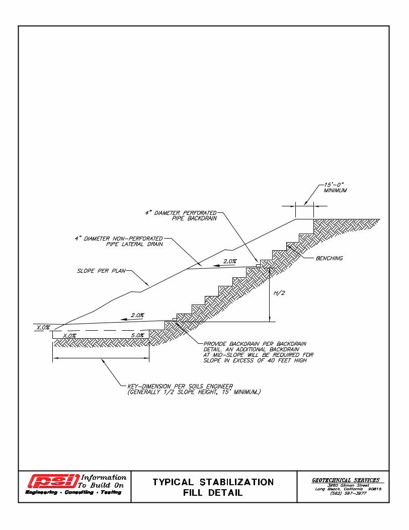
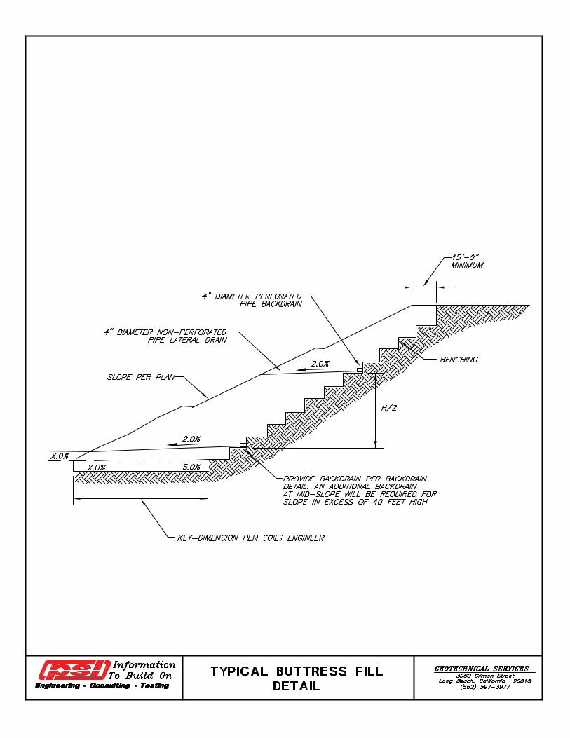
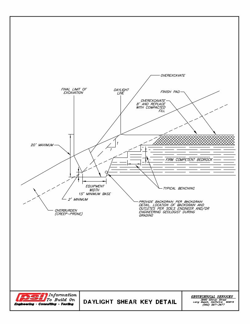
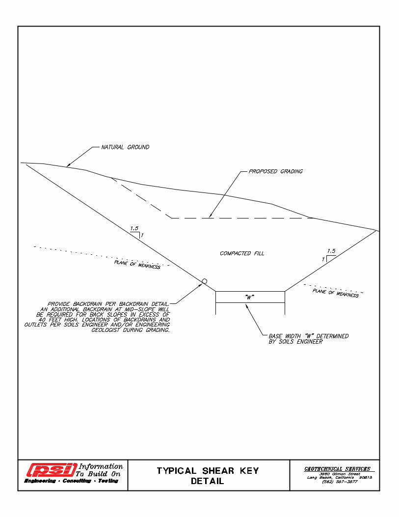
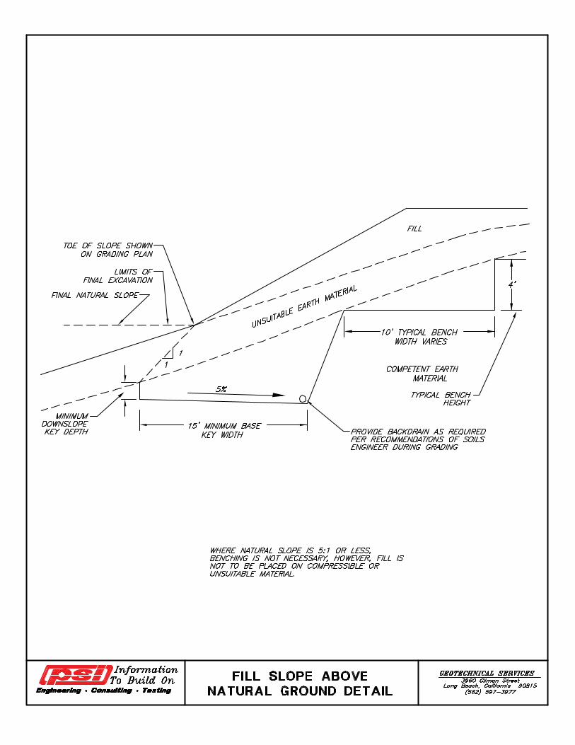
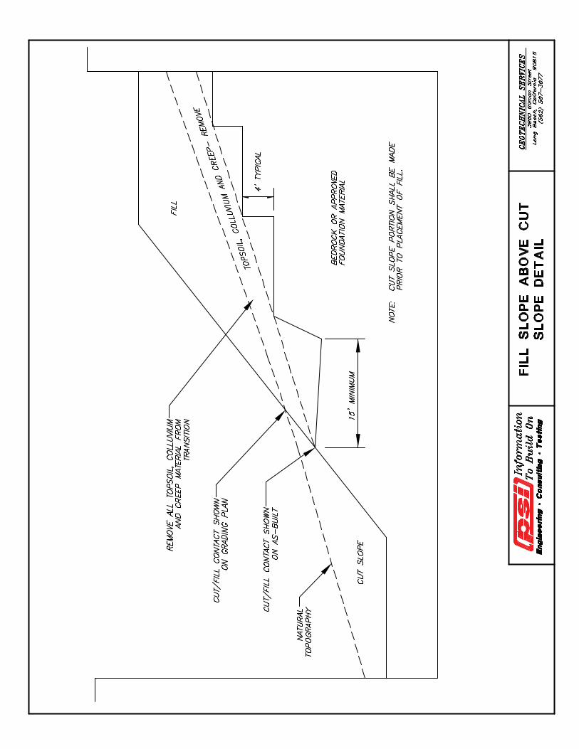
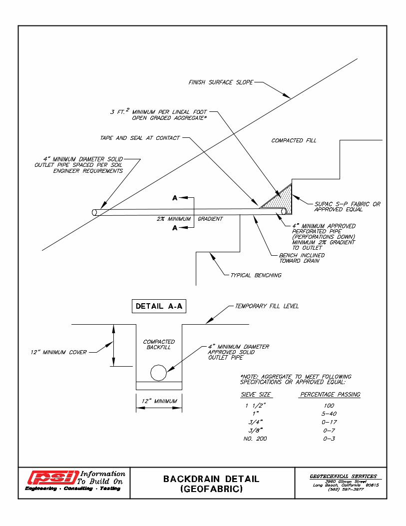
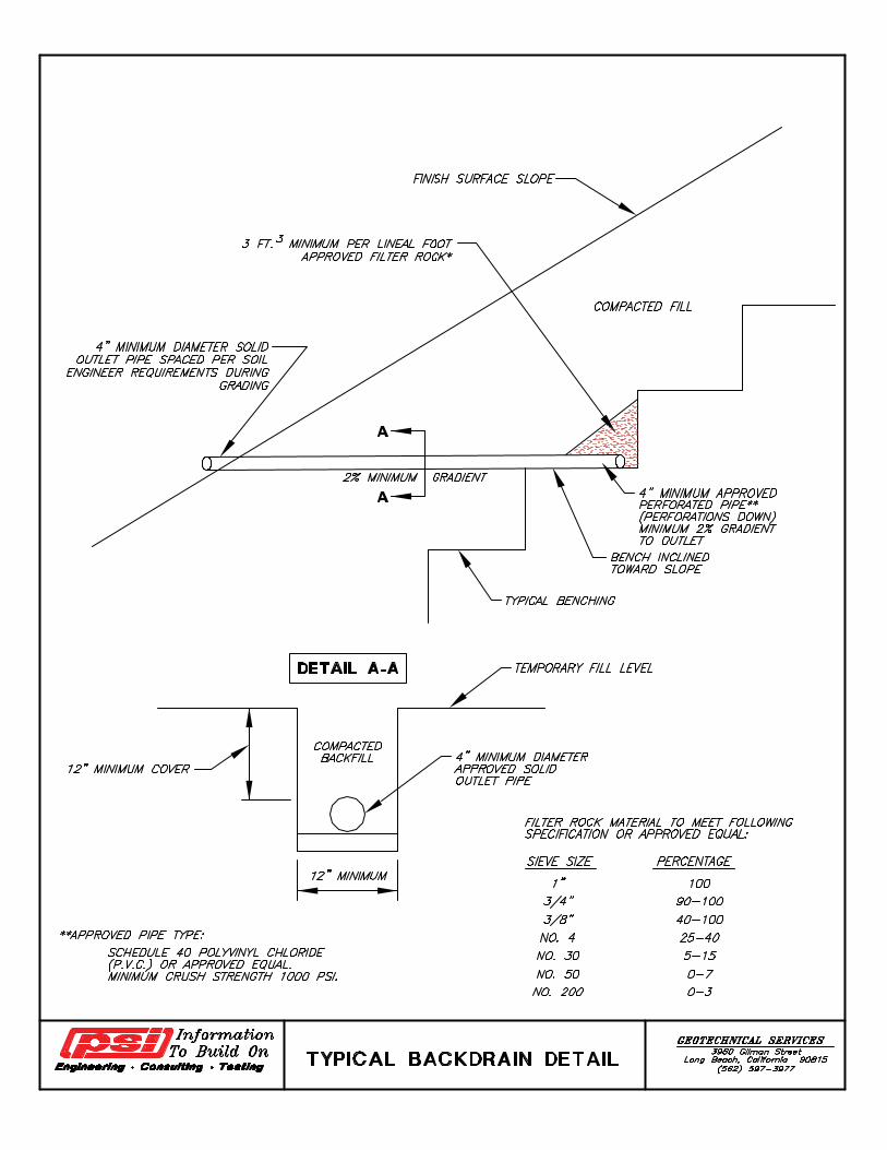
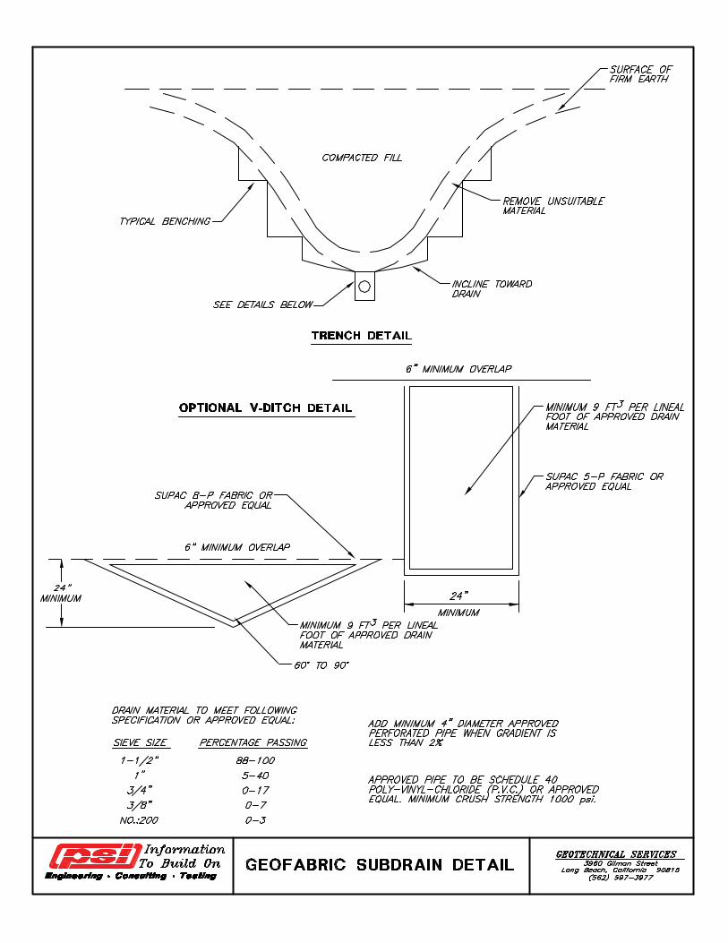
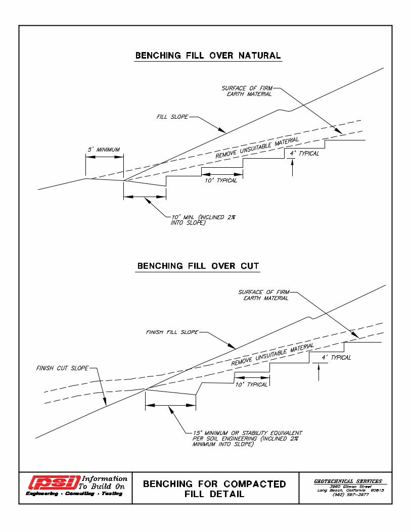
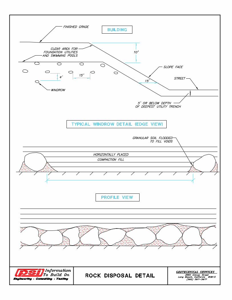
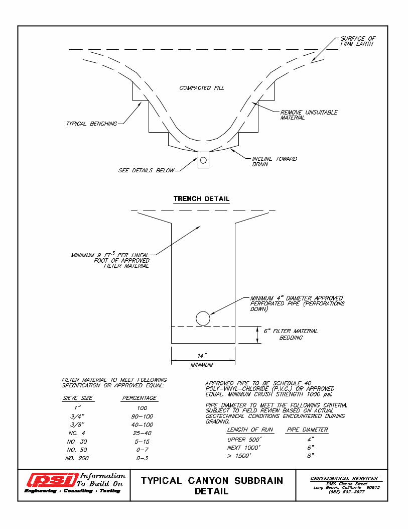
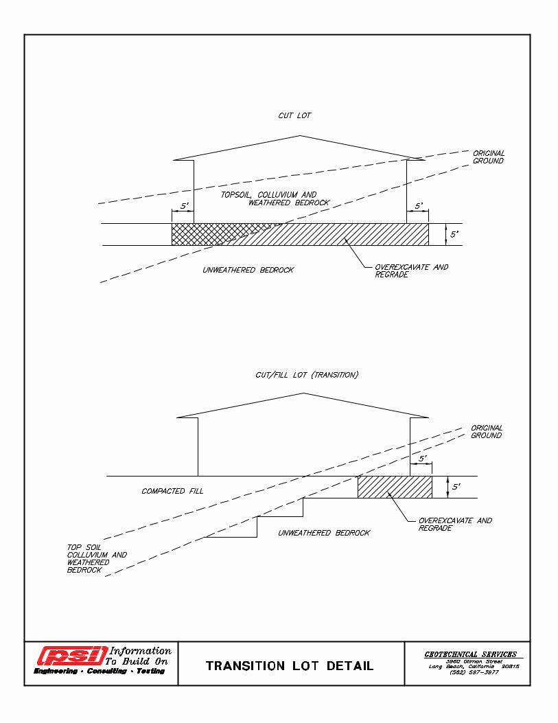
Appendix F
SWC Cannon Rd & Mystra Way Project No. 16081-01 Oceanside, California June 15, 2016
GeoMat Testing Laboratories, Inc. Appendix F-1
SLOPE MAINTENANCE GUIDELINES
Hillside lots in general, and hillside slopes in particular, need maintenance to continue to function and retain their value. Many homeowners are unaware of this and allow deterioration of their property. In addition to his own property, the homeowner may be subject to liability for damage occurring to neighboring properties as a result of his negligence. It is therefore important to familiarize homeowners with some guidelines for maintenance of their properties and make them aware of the importance of maintenance. Nature slowly wears away land, but human activities such as construction increase the rate of erosion 200, even 2,000 times that amount. When we remove vegetation or other objects that hold soil in place, we expose it to the action of wind and water, and increase its chance of eroding. The following guidelines are provided for the protection of the homeowner’s investment, and should be employed throughout the year.
(a) Care should be taken that slopes, terraces, berms (ridges at crown of slopes), and proper lot drainage are not disturbed. Surface drainage should be conducted from the rear yard to the street by a graded swale through the sideyard, or alternative approved devices.
(b) In general, roof and yard runoff should be conducted to either the street or storm drain by nonerosive devices such as sidewalks, drainage pipes, ground gutters, and driveways. Drainage systems should not be altered without expert consultation.
(c) All drains should be kept cleaned and unclogged, including gutters and downspouts. Terrace drains or gunite ditches should be kept free of debris to allow proper drainage. During heavy rain periods, performance of the drainage system should be inspected. Problems, such as gullying and ponding, if observed, should be corrected as soon as possible.
(d) Any leakage from pools, waterlines, etc. or bypassing of drains should be repaired as soon as possible.
(e) Animal burrows should be filled since they may cause diversion of surface runoff, promote accelerated erosion, and even trigger shallow soil failures.
(f) Slopes should not be altered without expert consultation. Whenever a homeowner plans a significant topographic modification of the lot or slope, a qualified geotechnical consultant should be contacted.
(g) If plans for modification of cut, fill, or natural slopes within a property are considered, an engineering geologist should be consulted. Any oversteepening may result in a need for
expensive retaining devices. Undercutting of the bottom of a slope might possibly lead to slope instability or failure and should not be undertaken without expert consultation.
(h) If unusual racking, settling, or earth slippage occurs on the property, the homeowner should consult a qualified soil engineer or an engineering geologist immediately.
(i) The most common causes of slope erosion and shallow slope failures are as follows:
Gross negligent of the care and maintenance of the slopes and drainage devices.
Inadequate and/or improper planting. (Barren areas should be replanted as soon as possible.)
Excessive or insufficient irrigation or diversion of runoff over the slope.
Foot traffic on slopes destroying vegetation and exposing soil to erosion potential.
(j) Homeowners should not let conditions on their property create a problem for their neighbors. Cooperation with neighbors could prevent problems; also increase the aesthetic attractiveness of the property.
WINTER ALERT It is especially important to “winterize” your property by mid-September. Don’t wait until spring to put in landscaping. You need winter protection. Final landscaping can be done later. Inexpensive measures installed by mid-September will give you protection quickly that will last all during the wet season. Check before storms to see that drains, gutters, downspouts,
and ditches are not clogged by leaves and rubble. Check after major storms to be sure drains are clear and
vegetation is holding on slopes. Repair as necessary. Spot seed any bare areas. Broadcast seeds or use a
mechanical seeder. A typical slope or bare areas can be done in less than an hour.
Give seeds a boost with fertilizer. Mulch if you can, with grass clippings and leaves, bark chips or
straw. Use netting to hold soil and seeds on steep slopes.
SWC Cannon Rd & Mystra Way Project No. 16081-01 Oceanside, California June 15, 2016
GeoMat Testing Laboratories, Inc. Appendix F-2
Check with your landscape architect or local nursery for advice. Prepare berms and ditches to drain surface runoff water away
from problem areas such as steep, bare slopes. Prepare base areas on slopes for seeding by raking the
surface to loosen and roughen soil so it will hold seeds.
CONSTRUCTION Plan construction activities during spring and summer, so that
erosion control measures can be in place when the rain comes. Examine your site carefully before building. Be aware of the
slope, drainage patterns and soil types. Proper site design will help you avoid expensive stabilization work.
Preserve existing vegetation as much as possible. Vegetation
will naturally curb erosion, improve the appearance and value of your property, and reduce the cost of landscaping later.
Use fencing to protect plants from fill material and traffic. If you
have to pave near trees, do so with permeable asphalt or porous paving blocks.
Minimize the length and steepness of slopes by benching,
terracing, or constructing diversion structures. Landscape benched areas to stabilize the slope and improve its appearance.
As soon as possible after grading a site, plant vegetation on all
areas that are not to be paved or otherwise covered.
TEMPORARY MEASURES TO STABILIZE THE SOIL
Grass provides the cheapest and most effective short-term erosion control. It grows quickly and covers the ground completely. To find the best seed mixtures and plants for your area, check with your local landscape architect, local nursery, or the U.S. Department of Agriculture Soil Conservation Service. Mulches hold soil moisture and provide ground protection from rain drainage. They also provide a favorable environment for starting and growing plants. Easy-to-obtain mulches are grass clippings, leaves, sawdust, bark chips, and straw. Straw mulch is nearly 100 percent effective when held in place by spraying with an organic glue or wood fiber (tackifiers), by punching it into the soil with a shovel or roller, or by tacking a netting over it. Commercial applications of wood fibers combined with various seeds and fertilizers (hydraulic mulching) are effective in stabilizing sloped areas. Hydraulic mulching with a tackifier should be done in two separate applications; the first composed of seed fertilizer and half the mulch, the second composed of the remaining mulch and tackifier. Commercial hydraulic mulch applicators – who also
provide other erosion control services – are listed under “landscaping” in the phone book. Mats of excelsior, jute netting, and plastic sheets can be effective temporary covers, but they must be in contact with the soil and fastened securely to work effectively. Roof drainage can be collected in barrels or storage containers or touted into lawns, planter boxes, and gardens. Be sure to cover stored water so you don’t collect mosquitoes. Excessive runoff should be directed away from your house. Too much water can damage tress and make foundations unstable.
STRUCTURAL RUNOFF CONTROLS Even with proper timing and planting, you may need to protect disturbed areas from rainfall until the plants have time to establish themselves. Or you may need permanent ways to transport water across your property so that it doesn’t cause erosion. To keep water from carrying soil from your site and dumping it into nearby lots, streets, streams and channels, you need ways to reduce its volume and speed. Some examples of what you might use are: Riprap (rock lining) – to protect channel banks from erosive
water flow. Sediment trap – to stop runoff carrying sediment and trap the
sediment. Storm drain outlet protection – to reduce the speed of water
flowing from a pipe onto open ground or into a natural channel. Diversion dike or perimeter dike – to divert excess water to
places where it can be disposed of properly. Straw bale dike – to stop and detain sediment from small-
unprotected areas (a short-term measure). Perimeter swale – to divert runoff from a disturbed area or to
contain runoff within a disturbed area. Grade stabilization structure – to carry concentrated runoff
down a slope.