Embed Size (px)
Citation preview

Appendix C Geotechnical Report


CITY OF LOS ANGELES DEPARTMENT OF PUBLIC WORKS
BUREAU OF ENGINEERING
GEOTECHNICAL ENGINEERING GROUP
GEOTECHNICAL ENGINEERING REPORT FIRE STATION #39 14614 WEST AETNA STREET TRACT: TR 1200, BLOCK: 70, LOT: FR2/FR3 LOS ANGELES, CALIFORNIA W.O. #E170094B GEO FILE # 12-002 FEBRUARY 15, 2013


Fire Station #39 February 15, 2013
TABLE OF CONTENTS
1.0 INTRODUCTION 1
2.0 PROJECT SCOPE 1
3.0 EXPLORATION PROGRAM 1
4.0 LABORATORY TESTING 2
Table 1 — Soil Design Parameters 3
5.0 REGIONAL GEOLOGY 3
6.0 SITE CONDITIONS 3
6.1 SURFACE CONDITIONS 3
6.2 SUBSURFACE CONDITIONS 4
6.3 CHEMICAL TESTING 4
6.4 GROUNDWATER 4
6.5 INFILTRATION TESTING OF ALLUVIUM 5
Table 2 - Summary of Infiltration Test Results 5
7.0 FAULTING AND SEISMICITY 5
7.1 GROUND MOTION 6
7.2 LIQUEFACTION 6
7.3 OTHER SEISMIC HAZARDS 7 7.4 SEISMIC DESIGN PARAMETERS 7
Table 3 — Seismic Design Parameters 8
8.0 SITE RECOMMENDATIONS 8
8.1 GENERAL 8
8.2 SITE PREPARATION AND EARTHWORK 9
8.2.1 Site Clearing 9
8.2.2 Over-Excavation 9
8.2.3 Temporary Excavations 9
8.2.4 Slot Cuts 10
8.2.5 Temporary Shoring 10 8.2.6 Design and Installation of Pile-Supported Shoring 11
8.2.7 Subgrade Preparation 12
8.2.8 Fill Materials 13
8.2.9 Fill and Backfill Placement 13 8.2.10 Shrinkage Factors 14 8.2.11 Controlled Low Strength Material for Non-Structural Backfill 14
8.2.12 Trench Backfill 15 8.2.13 Fill Certification 15
8.3 SHALLOW SPREAD AND CONTINUEOUS FOOTINGS 15
8.4 RETAINING WALLS 16
8.5 PLANTER AND FENCE WALL AND NON-STRUCTURAL FOUNDATIONS 17

Fire Station #39 February 15, 2013
8.6 BUILDING SLAB-ON-GRADE 17
8.7 PRELIMINARY ASPHALT CONCRETE PAVEMENT DESIGN 17
Table 4 — Asphalt Concrete Pavement Sections 18
8.8 REINFORCED CONCRETE PAVEMENT DESIGN 18
8.9 CEMENT TYPE AND CORROSION MEASURES 18
9.0 SUPPLEMENTAL GEOTECHNICAL SERVICES 19
9.1 REVIEW OF PLANS AND SPECIFICATIONS 19
9.2 GEOTECHNICAL OBSERVATION AND TESTING DURING CONSTRUCTION 19
10.0 CLOSURE 19
Plate 1 — Vicinity Map Plate 2 — Proposed Site Plan Plate 3 — Boring Location Map Plate 4 — Regional Geology Plate 5 — Seismic Hazard Zones
Appendix A — Standards-Report of Subsurface Investigation dated 5/15/12 Appendix B — Standards-Report of Subsurface Investigation dated 7/16/12 Appendix C — Standards-Report of Subsurface Investigation dated 9/10/12 Appendix D — Standards-Report of Subsurface Investigation dated 8/8/12 Appendix E — Contingency Contaminated Material Recommendations Appendix F — Probabilistic Seismic Hazard Analyses Appendix G — Liquefaction Analysis

Fire Station #39 February 15, 2013 GEO File No. 12-002
WO #: El 7009413 Page 1
1.0 INTRODUCTION
This report presents the results of a geotechnical investigation conducted for the Fire Station #39 at 14614 West Aetna Street in the City of Los Angeles. A vicinity map of the project site is shown on Plate 1. This investigation was conducted to evaluate subsurface characteristics and to provide geotechnical recommendations for design and construction of the project. The Geotechnical Engineering Group (GEO) prepared this report in response to a request from the Bond Programs Division.
This report is based on visual observation, subsurface investigation and laboratory testing. At the request of GEO, Department of General Services, Standards Division (Standards) performed subsurface exploration, infiltration testing, contamination testing at the site and laboratory testing of samples collected from the site. The results of their field investigation and laboratory tests are included in their Report of Subsurface Investigation (Appendix A) dated May 15, 2012 (received by GEO on June 6, 2012), Report of Subsurface Investigation Supplemental (Appendix B) dated July 16, 2012 (received by GEO on August 20, 2012), Report of Subsurface Investigation Supplemental (Appendix C) dated September 10, 2012 (received by GEO on September 28, 2012) and Report of Subsurface Investigation Contamination (Appendix D) dated August 8, 2012 (received by GEO on August 20, 2012). GEO has reviewed the reports presented in Appendix A, B, C and D, concurs with and accepts responsibility for the use of their contents.
2.0 PROJECT SCOPE
As shown on the Proposed Site Plan, Plate 2, the project will involve demolition of an existing parking lot on the project site and construction of a new 17,400 square feet fire station and other minor improvements.
Final site grades are expected to be within a few feet of the current site grades. If the project scope is modified to include underground construction, additional or larger structures, or relocation of improvements, this report should not be considered adequate for design or construction of the modified project scope. In such case, a supplemental report to address the altered scope will be required.
3.0 EXPLORATION PROGRAM
Seventeen exploratory borings were drilled in the area of the proposed construction to depths ranging from 11 feet to 51 feet below the ground surface (bgs). The exploratory borings were drilled using a truck-mounted drill rig with 6-inch diameter conventional flight augers or 8-inch diameter hollow stem augers. Borings B-1, B-2, B-4, B-6, B-7, B-8 and H-1 were advanced to depths of 31 feet bgs. Boring B-5 was advanced to a depth of 11 feet bgs. Borings B-9 to B-15 were advanced to depths of 25 feet bgs. Standard Penetration Tests (SPT) samples were collected from borings B-3 and B-17. Each SPT were advanced to a total depth of approximately 51 feet bgs. Approximate locations of the borings are depicted on the Boring Location Map, Plate 3.
Standard Penetration Test (SPT) samples were collected from boring B-3 and B-17 at depths of 2.5 feet, 5 feet, 10 feet and every 5 feet thereafter to the explored depth of

Fire Station #39 February 15, 2013 GEO File No. 12-002
WO #: El 70094E3 Page 2
approximately 51 feet bgs. Ring samples were collected from borings B-1, B-2, B-4, B-5, B-6, B-7 and B-8 at depths of 2.5 feet, 5 feet, 7.5 feet, 10 feet and every 5 feet thereafter to the explored depth of approximately 31 feet bgs. No ring samples were collected from boring B-5 and borings B-9 to B-15. Ring samplers were driven into the bottom of the borings with successive drops of a 300-pound hammer falling 30 inches. SPT samplers were driven into the bottom of the borings with successive drops of a 140-pound automatic-trip hammer falling 30 inches. Blows required to advance the ring and SPT samplers every six inches of penetration are shown on the boring logs (Appendices A and C). For the SPT samples, the number of hammer blows required to advance the SPT sampler the last 12 inches of an 18-inch sample interval is the SPT field "N" value. Bulk samples were also collected from the upper few feet of each boring.
Each collected sample was inspected and described in general conformance with the Unified Soil Classification System (USCS). The descriptions were entered on the boring logs, which are presented in Appendices A, C and D of this report. All samples were sealed and packaged for transportation to the Standards laboratory. After completion of drilling, borings were backfilled with soil cuttings.
Boring B-5 was converted to a monitoring well that was installed by Standards. A description and schematic diagram of the monitoring well installation is shown on the log of boring B-5 in the Standards report. Infiltration testing was conducted with the monitoring well as discussed below. After completion of the infiltration testing, the well was removed and the hole was backfilled with site soils.
Screening in the field for volatile organic compounds (VOCs) was performed to evaluate whether fuel spills or other contamination of the soil has occurred in the project area. Organic Vapor Analyzer (OVA) readings and Lower Explosive Limit (LEL) readings on soil samples were screened in the field with a portable Photovac Inc. Model Microfid I/SC EXIA and RKI Instruments Model Eagle devices. All readings were non detect at each sample depth and on bulk soil sample bags.
4.0 LABORATORY TESTING
Selected soil samples were tested for the following properties:
In-Place Dry Density and Field Moisture (ASTM D2937)
• Laboratory Maximum Dry Density and Optimum Moisture Content (ASTM D1557)
• Consolidation (ASTM D2435)
• Direct Shear (ASTM D3080)
• Sieve and Hydrometer Analysis (ASTM D422)
• Liquid Limit and Plasticity Index (ASTM D4318)
• R-Value Tests (California Test Method No. 301)
• Acidity (SM 2310B)
• Conductivity (EPA 120.1)

Fire Station #39
February 15, 2013 GEO File No. 12-002
WO #: El 70094E3 Page 3
• Chlorides (EPA 300.0)
• pH (SM 4500-H+B)
• Sulfates (EPA 300.0)
Laboratory test results are presented in the enclosed Report of Subsurface Investigations (Appendices A, B, C and D). Soil parameters used for design purposes are summarized in Table 1, Soil Design Parameters.
TABLE 1 - SOIL DESIGN PARAMETERS
Material Soil Type Unit Weight Cohesion Friction Compacted Fill
Lean Clay with Sand (CL)
129 pcf 310 psf 31°
Native Soil Sandy Lean Clay (CL)
125 pcf 70 psf 36°
Native Soil Silt with Sand (ML)
110 pcf 170 psf 31°
5.0 REGIONAL GEOLOGY
As shown on the Regional Geology, Plate 4, the proposed project site is located within the Transverse Ranges Geomorphic Province of southern California. The Transverse Ranges are characterized by roughly east-west trending, convergent deformational structural features (linear topography, folding, and faulting) in contrast to the predominant northwest-southeast structural trend found in the other geomorphic provinces in California. Uplift of the mountain ranges has resulted in erosion and subsequent deposition of alluvium in the valleys.
The site is situated within the south-central portion of the San Fernando Valley, which is a broad elongated, east-west trending, structural trough that is approximately 22 miles long and ranges between 9 and 12 miles in width. The San Fernando Valley has become filled in with Quaternary-age alluvial sediments originating from the Santa Susana and San Gabriel Mountains to the north, the Santa Monica Mountains to the south, the Verdugo Mountains to the east, and the Simi Hills to the west. The mountain ranges surrounding the San Fernando Valley are composed of rocks varying in age ranging from the Pre-Cambrian on to the Quaternary period.
6.0 SITE CONDITIONS
6.1 SURFACE CONDITIONS
The project site is located at 14614 West Aetna Street in the City of Los Angeles. The area currently consists of a flat asphalt parking lot with chain link fencing. A portion of the asphalt parking will be demolished and a new 17,400 square feet fire station will be constructed.
Fire Station #39 February 15, 2013 GEO File No. 12-002
WO #: El 700948 Page 4
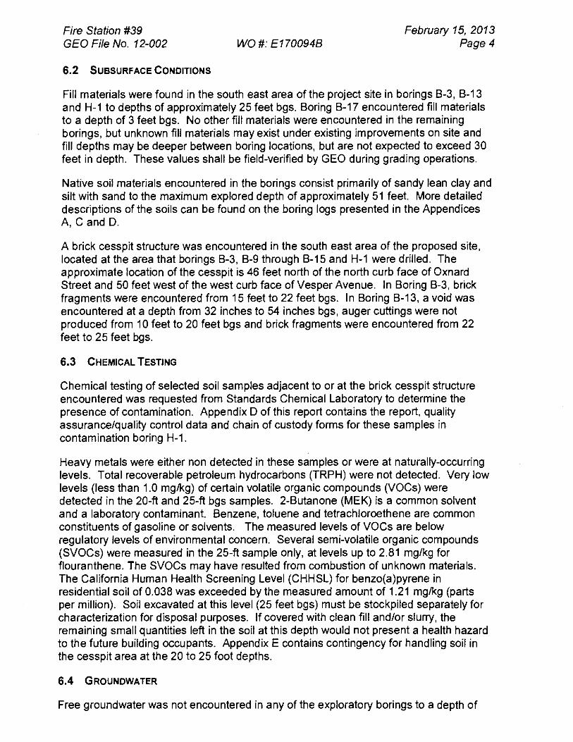
6.2 SUBSURFACE CONDITIONS
Fill materials were found in the south east area of the project site in borings B-3, B-13 and H-1 to depths of approximately 25 feet bgs. Boring B-17 encountered fill materials to a depth of 3 feet bgs. No other fill materials were encountered in the remaining borings, but unknown fill materials may exist under existing improvements on site and fill depths may be deeper between boring locations, but are not expected to exceed 30 feet in depth. These values shall be field-verified by GEO during grading operations.
Native soil materials encountered in the borings consist primarily of sandy lean clay and silt with sand to the maximum explored depth of approximately 51 feet. More detailed descriptions of the soils can be found on the boring logs presented in the Appendices A, C and D.
A brick cesspit structure was encountered in the south east area of the proposed site, located at the area that borings B-3, B-9 through B-15 and H-1 were drilled. The approximate location of the cesspit is 46 feet north of the north curb face of Oxnard Street and 50 feet west of the west curb face of Vesper Avenue. In Boring B-3, brick fragments were encountered from 15 feet to 22 feet bgs. In Boring B-13, a void was encountered at a depth from 32 inches to 54 inches bgs, auger cuttings were not produced from 10 feet to 20 feet bgs and brick fragments were encountered from 22 feet to 25 feet bgs.
6.3 CHEMICAL TESTING
Chemical testing of selected soil samples adjacent to or at the brick cesspit structure encountered was requested from Standards Chemical Laboratory to determine the presence of contamination. Appendix D of this report contains the report, quality assurance/quality control data and chain of custody forms for these samples in contamination boring H-1.
Heavy metals were either non detected in these samples or were at naturally-occurring levels. Total recoverable petroleum hydrocarbons (TRPH) were not detected. Very low levels (less than 1.0 mg/kg) of certain volatile organic compounds (VOCs) were detected in the 20-ft and 25-ft bgs samples. 2-Butanone (MEK) is a common solvent and a laboratory contaminant. Benzene, toluene and tetrachloroethene are common constituents of gasoline or solvents. The measured levels of VOCs are below regulatory levels of environmental concern. Several semi-volatile organic compounds (SVOCs) were measured in the 25-ft sample only, at levels up to 2.81 mg/kg for flouranthene. The SVOCs may have resulted from combustion of unknown materials. The California Human Health Screening Level (CHHSL) for benzo(a)pyrene in residential soil of 0.038 was exceeded by the measured amount of 1.21 mg/kg (parts per million). Soil excavated at this level (25 feet bgs) must be stockpiled separately for characterization for disposal purposes. If covered with clean fill and/or slurry, the remaining small quantities left in the soil at this depth would not present a health hazard to the future building occupants. Appendix E contains contingency for handling soil in the cesspit area at the 20 to 25 foot depths.
6.4 GROUNDWATER
Free groundwater was not encountered in any of the exploratory borings to a depth of

Fire Station #39 February 15, 2013 GEO File No. 12-002
WO #: El 70094E3 Page 5
51 feet bgs. Groundwater data obtained from California Division of Mines and Geology (CDMG, 1998) indicates that the shallowest reported historic depth to groundwater in the site area was on the order of 15 feet bgs.
6.5 INFILTRATION TESTING OF ALLUVIUM
Prior to infiltration testing, the test well was filled with water and left overnight to soak the surrounding soil. After the soaking period, infiltration testing was initiated by filling the well casing with water. As water began to infiltrate, the established water level was kept relatively constant by adding water at predetermined time increments. The amount of water added during each time increment to maintain the constant water level was recorded on field data sheets. The test lasted eight hours and concluded as the infiltration rate appeared to stabilize. The data sheets are provided in the Report of Subsurface Investigation included in Appendix A of this report.
A summary of field saturated hydraulic conductivity values for the site is provided in Table 2, below. A factor of safety was not applied to the values presented in the table.
TABLE 2 - SUMMARY OF INFILTRATION TEST RESULTS
Test Well ID
Infiltration Zone (feet below the
ground surface)
Saturated Hydraulic Conductivity (feet/second)
Saturated Hydraulic Conductivity
(centimeters/second)
USCS Soil Type
B-5/TVV-1 5 to 10 1.8 x 10 -5 5.5 x 10⁻⁴ CL
The results of infiltration testing presented here is indicative of the infiltration rates that may be encountered near the test well locations, but should not be considered as a guarantee of infiltration conditions. Minor changes in soil composition can cause significant differences in infiltration rates. The parameters above should only be used for design by those with an understanding of the limitations of the testing method and complexities of subsurface drainage.
7.0 FAULTING AND SEISMICITY
The fault classification system adopted by the CDMG, relative to State legislation delineating Earthquake Fault Zones along active or potentially active faults (Alquist-Priolo Act), is used for structures. CDMG defines an active fault (or fault zone) as a fault that has moved within Holocene time (about the last 11,000 years). Faults with no known displacement within Holocene time that showed evidence of movement during Quaternary time (the last 1.6 million years) have been defined as potentially active.
In addition, the State has also established a Seismic Hazard Mapping Act to provide statewide seismic hazard mapping and technical advisory program. The purpose of this legislation was to assist cities and counties in fulfilling their responsibilities for protecting the public health and safety from the effects of strong ground shaking, liquefaction, landslides, or other ground failure hazards caused by earthquakes.
Ground surface rupturing along faults, ground shaking and liquefaction are three of the

Fire Station #39 February 15, 2013 GEO File No. 12-002
WO #: El 700948 Page 6
important seismic considerations for properties in Southern California. The site is not located within an Alquist-Priolo Earthquake Fault Zone (Hart, 1997) (formerly known as Special Studies Zones). Thus, the potential for ground surface rupture impacting the site is considered low. As shown on the Seismic Hazard Zones, Plate 5, the site is within a liquefaction Seismic Hazard Zone, but not located within a landslide Seismic Hazard Zone (CDMG, 1998). Based on the current understanding of the geologic framework of the site area, the seismic hazard which is expected to have the highest probability of affecting the site is ground shaking resulting from an earthquake occurring along any of several major active and potentially active faults in Southern California. Known regional faults that could produce significant ground shaking at the site include the Verdugo, Hollywood, Santa Monica, Northridge, and among others. The closest of these is the Verdugo Fault with a surface projection of potential rupture area located at a distance of approximately 8.8 kilometers (km) from the site.
7.1 GROUND MOTION
A probabilistic seismic hazard analysis was performed using the computer program FRISKSP (Blake, 1998b) in order to estimate the Peak Ground Acceleration (PGA) that could occur at the site, based on recurrence interval. The probabilistic analysis considered various magnitudes of earthquakes, along their respective fault lengths, that could occur along active or potentially active faults within a 100-km radius of the site. Standard deviation was applied during the analysis to assess the uncertainty inherent in the calculation with respect to magnitude, distance, and ground motion. An average of three attenuation relationships (Boore et al.-NEHRP Class D site, 1997; Campbell and Bozorgnia-Alluvium, 1994/1997; and Sadigh-Deep Soil, 1997) were used to estimate ground motions at the site for multiple distance/magnitude calculation combinations inherent in the probabilistic analysis.
The results of the probabilistic seismic hazard analysis suggest a maximum probable earthquake, MPE, (10 percent probability of exceedance in 50 years — 475 year return period) ground acceleration of 0.56g for the site. The upper bound earthquake, UBE, (10 percent probability of exceedance in 100 years — 950 year return period) ground acceleration was estimated to be approximately 0.67g. The results of the probabilistic analysis in terms of probability of exceedance, as well as average return period (ARP), are included in Appendix F of this report.
7.2 LIQUEFACTION
The site is shown on the State of California Seismic Hazard Zones map as being within an area that has potential for liquefaction. Liquefaction typically occurs when near surface (usually upper 50 feet), saturated, clean, fine-grained loose sands are subject to intense ground shaking.
Free groundwater was not encountered in any of the exploratory borings to a depth of 51 feet bgs. Groundwater data obtained from California Division of Mines and Geology (CDMG, 1998) indicates that the shallowest reported historic depth to groundwater in the site area was on the order of 15 feet bgs. Based on this data, the potential for liquefaction at the site is considered significant. Analysis of the site indicates that the potential liquefaction-induced settlement is on the order of 0.3 inches. Calculations and analysis are attached in Appendix G.

Fire Station #39 February 15, 2013 GEO File No. 12-002 WO #: El 70094E3 Page 7
7.3 OTHER SEISMIC HAZARDS
In addition to surface fault rupture, ground shaking, and liquefaction, other effects of seismic activity include landsliding, lateral spreading, earthquake-induced flooding, seiches, and tsunamis. Results of a site-specific evaluation of the potential for these effects affecting the project site are presented below:
• Earthquake-Induced Flooding: This is flooding caused by failure of dams or other water-retaining structures as a result of earthquakes. Based on the site location, the potential of earthquake-induced flooding of the site is considered to be low.
• Landslides: Seismically-induced landslides and other slope failures are common occurrences during or soon after earthquakes. The project site and surrounding area is relatively flat. In the absence of significant ground slopes, the potential for seismically induced landslides affecting the proposed site is low.
• Lateral Spreading: Seismically-induced lateral spreading involves primarily lateral movement of earth materials due to ground shaking. It differs from slope failure in that complete ground failure involving large movement does not occur due to the relatively smaller gradient of the initial ground surface. Lateral spreading is demonstrated by near-vertical cracks with predominantly horizontal movement of the soil mass involved. Based on the materials encountered in our borings and with consideration to the depth of historic and current groundwater levels, the potential for lateral spreading of the project area is low.
• Seiches: Seiches are large waves generated in enclosed bodies of water in response to ground shaking. The site is not located adjacent to any enclosed large bodies of water that could experience seiches during an earthquake. Thus, the potential for seiches impacting the site is considered low.
• Tsunamis: Tsunamis are tidal waves generated in large bodies of water by fault displacement or major ground movement. Based on the location of the site, the potential impact of a tsunami is considered to be low.
7.4 SEISMIC DESIGN PARAMETERS
Table 1613.5.2 of the 2011 Los Angeles Building Code Building Code "Site Class Definitions" list six Site Classes (A through F). The Site Class is based on the average properties of the upper 100 feet of the soil and/or bedrock beneath the site. The appropriate Site Class is chosen by referencing the average shear wave velocity, average Standard Penetration Test (SPT) blow counts, and/or average undrained shear strength. In addition, the Site Class selection also considers profiles containing soft clay, peaty and/or highly organic clays, very high plasticity clays, very thick soft/medium clays, and soils vulnerable to failure or collapse under seismic loading such as liquefiable soils, quick and highly sensitive clays and collapsible weakly cemented soils. Based on data obtained from the deepest boring and our analyses, Site Class D was selected for this site.
As the site is subject to liquefaction-induced settlement, Site Class F would apply and require a site-specific analysis. Our understanding of the project scope indicates that proposed site structures will have a fundamental period of vibration less than 0.5 seconds and therefore a site-specific analysis is not required per the exception noted in

Fire Station #39 February 15, 2013 GEO File No. 12-002
WO #: E1700948 Page 8
Section 20.3.1 of the ASCE 7 design procedures. If any site structures have a fundamental period of vibration greater than 0.5 seconds, GEO shall be notified and supplemental recommendations and seismic design parameters will be provided for a Site Class F classification. The project plans shall explicitly note the fundamental period of vibration for new structures to confirm compliance with this assumption.
The mapped acceleration parameters Ss and Si, 0.2 and 1-second spectral response accelerations, were determined and used along with the Site Class to obtain the site coefficients Fa and Fv. The maximum considered earthquake spectral response acceleration for short periods, SMS, and at the 1.0-second period, SM1, adjusted for Site Class effects were then calculated followed by the calculation of the design spectral response acceleration for short periods, Sps, and at the 1.0-second period, SDI. The values of To and Ts, in seconds, were then determined using the equations presented in the code to represent the beginning and end of the design response spectra peak.
The seismic parameter values for the site are summarized in Table 3, Seismic Design Parameters.
TABLE 3 — SEISMIC DESIGN PARAMETERS
Parameter Value 2011 LABC Reference
Site Class D Table 1613.5.2
Ss 2.226 Figure 1613.5(3)
Si 0.775 Figure 1613.5(4)
S MS 2.226 Equation 16-37
SM1 1.163 Equation 16-38
SDS 1.484 Equation 16-39
Sal 0.775 Equation 16-40
To (seconds) 0.104 Chapter 16
Ts (seconds) 0.522 Chapter 16
8.0 SITE RECOMMENDATIONS
8.1 GENERAL
Our primary geotechnical consideration with respect to the proposed construction is the deep fills and potential liquefaction. Based on our analysis of data collected during the subsurface investigation, the fire station may be supported on shallow spread and/or continuous footing.
Detailed geotechnical engineering recommendations addressing the surficial soils, site preparation, site earthwork, foundations, retaining walls and slabs-on-grade are presented in the remaining portions of this report. The following opinions, conclusions, and recommendations are based on the properties of materials encountered in the

Fire Station #39 February 15, 2013 GEO File No. 12-002
WO #: E170094B Page 9
exploratory borings and laboratory test results.
A representative of GEO will need to provide observation and testing services during site earthwork and construction of foundations. This will allow us the opportunity to compare actual conditions with those encountered in the exploratory borings and, if necessary, to expedite supplemental recommendations if warranted by the exposed subsurface conditions. We shall also review the preliminary foundation and earthwork plans and specifications. This review will provide us an opportunity to detect misinterpretation or misunderstandings of our recommendations prior to the start of construction.
8.2 SITE PREPARATION AND EARTHWORK
8.2.1 Site Clearing
Prior to construction, all organic or inorganic materials shall be removed from the construction area and disposed of outside the site. Any existing structural or landscape elements within these areas, including any foundation elements, shall be demolished and removed from the site. Any utilities, whether active or inactive, shall be identified and removed from the site or relocated per project plans and specifications. Any cavities resulting from removal of any existing foundations or utility lines shall be properly backfilled and compacted in accordance with the following sections.
8.2.2 Over-Excavation
All existing fill materials within the area of the proposed building shall be over-excavated to suitable, undisturbed natural soil and replaced with compacted fill. If foundations for the new building are to be supported on compacted fill soils, foundations areas shall be over-excavated to a depth of 5 feet below existing site grade or to a depth of 3 feet below the bottom of proposed footings, whichever is deeper, and replaced with compacted fill. Slab-on-grade areas within the building shall be over-excavated to suitable undisturbed natural soil or a minimum of 12 inches below the design subgrade elevation; whichever is deeper, and replaced with compacted fill soil. Over-excavation depths may have to be greater in some areas to remove unsuitable soils. Removal excavations should extend a horizontal distance beyond the edges of the foundations equal to the depth of over excavation below the footings or a minimum of three feet, whichever is greater.
Paved areas and areas below non-structural planter and fence walls shall be overexcavated to a depth of at least 24 inches below existing grade or designed subgrade elevation, whichever is deeper. The excavation shall extend laterally beyond the edge of paving or footings a minimum distance of 3 feet or to site property lines, whichever is smaller. Additional excavation may be required to remove unsuitable soils, but removal of all fill materials below the required excavation depth is not necessary for these areas.
8.2.3 Temporary Excavations
Based on our observations during subsurface investigation and results of laboratory tests, the materials at the site should be readily excavated by conventional earthmoving equipment in good operating condition. All temporary excavations shall conform to the

Fire Station #39 February 15, 2013 GEO File No. 12-002
WO #: El 700948 Page 10
State of California Construction Safety Orders (CAL/OSHA). Unsurcharged, temporary vertical excavations can be a maximum depth of 5 feet. Unsurcharged excavations greater than 5 feet and to a maximum of 20 feet shall be sloped at a 1:1 (H:V) or flatter inclination from the ground surface to the bottom of the excavation or should be shored. Excavations greater than 30 feet are not anticipated for the project. Any excavation that enters the influence zone of an adjacent structure or right-of-way subject to vehicle loading shall utilize slot cuts or shoring.
8.2.4 Slot Cuts
Slot cuts for unsurcharged excavations may be used per the following recommendations:
• The excavation side shall be initially sloped uniformly at an inclination of 1:1 (horizontal to vertical) from the top of the slope to the bottom of the over-excavation.
• Slots shall be constructed in an A, B, C sequence with neither adjacent slot excavated until the slot is completely backfilled to the grade of the initial 1:1 slope (horizontal to vertical).
• Maximum width of slots shall not exceed 8-feet and maximum height of slots shall not exceed 8-feet.
• Prior to placing of any fill in any slots, the bottom of each slot shall observed and approved by a representative of GEO and the City of Los Angeles Grading Inspector.
• Fill shall be placed in lifts not exceeding 8-inches in thickness shall be moisture conditioned and compacted in accordance with the requirements of Section 8.2.9 of this report.
• Following completion of the slot cutting, all fill placed adjacent to the initial 1:1 slope (horizontal to vertical) shall be benched into the slope in accordance with the 2011 LABC requirements.
• All excavation of the slots shall be performed under the continuous observation of the geotechnical engineer of record or a GEO representative working under direct supervision of the geotechnical engineer of record.
• The GEO representative working under the supervision of the geotechnical engineer of record shall be able to take the place of a Building and Safety Deputy-Grading inspector for purposes of slot-cut inspection and approval in the field.
• Backfill placed in the slots shall be tested for compaction as it is placed.
If excessive sloughing and caving occurs, slot cuts shall be backfilled immediately and shoring shall be installed. If necessary, recommendations can be provided for slot cutting of surcharged excavations on a case by case basis.
8.2.5 Temporary Shoring
Shoring may be designed in accordance with Section 306-1.1.6 of the Standard Specification for Public Works Construction, latest edition (SSPWC), Title 8, Division 1, Chapter 4, Subchapter 4 of the California code of Regulations: CAL/OSHA Construction Safety Orders and/or the lateral earth pressure distributions recommended herein.

Fire Station #39 February 15, 2013 GEO File No. 12-002
WO #: El 700948 Page 11
Based on the soil classification of the Construction Safety Orders, the existing fill soils and natural materials at the project site shall be considered to be Type B soil. Cantilevered shoring shall be designed to withstand an active equivalent fluid pressure (EFP) of 30 pcf. Cantilevered shoring is not recommended adjacent to existing structures or utilities that cannot tolerate at least 1/2 inch of lateral or vertical movement. Braced shoring is recommended in areas where shoring will be located close to existing structures and/or utilities where it is necessary to limit shoring deflections. Braced shoring can be designed using a uniform rectangular soil pressure of 26H pounds per square foot, where H is equal to the depth of the excavation in feet being shored. These design pressures assume a level backslope. These shoring pressures are for unsurcharged excavations only. If an existing improvement is within a distance equal to the total depth of excavation, additional recommendations for surcharge loads will be required.
A surcharge load equivalent to an additional 2 feet of retained soil shall be applied to the upper 10 feet of the shoring for the light vehicular traffic anticipated to pass within 0.7H feet of the face of the shoring, or 20 feet, whichever is less.
If heavier traffic loads are anticipated near the top of the shoring, additional analysis will be required. Wheel or outrigger loads of heavy construction equipment that are located within a distance equal to 0.7H feet of the face of the shoring shall be considered as surcharge loads in shoring calculations.
All proposed shoring system designs including supporting documentation and calculations shall be submitted to GEO for review and approval in reference to existing soil conditions. All shoring systems must meet the following minimum requirements to be considered for review.
• Shoring shall directly support the sides of the excavation. Shoring shall be designed to minimize the development and presence of voids behind shoring support.
• Shoring shall utilize solid sheeting or continuous support to minimize ground loss. Any voids developed behind shoring shall be immediately filled with Controlled Low Strength Material (CLSM) material.
• Shoring installation procedures shall be designed so that no person is required to enter an unsupported excavation greater than 5 feet in depth at any time.
8.2.6 Design and Installation of Pile-Supported Shoring
When shoring consists of soldier piles and lagging, drilled holes for soldier piles shall be backfilled with Controlled Low Strength Material (CLSM, Greenbook Section 201, with a minimum of one sack of Portland cement per cubic yard of slurry and a maximum of two sacks of Portland cement per cubic yard of slurry) from the bottom of the drilled hole to the ground surface. Alternatively, drilled holes can be backfilled with structural concrete (from the bottom of the drilled hole to the proposed depth of excavation) and slurry above the proposed excavation depth.
For shoring embedded beneath the bottom of the excavation, the allowable passive bearing pressure may be taken as an equivalent fluid pressure of 300 pounds per square foot per foot of depth (psf/ft) to a maximum of 3,000 psf.

Fire Station #39 February 15, 2013 GEO File No. 12-002
WO #: El 70094E3 Page 12
Passive pressures presented in this report are based on the assumption that slurry or concrete will be used to backfill the soldier piles. Use of granular backfill would result in larger deflections and a significant decrease in the allowable passive resistance and therefore is not acceptable. If slurry is used as backfill below the proposed depth of excavation, then the effective width of the pile for the purpose of calculating passive resistance shall be taken as the width of the steel beam. If structural concrete is used then the effective width of the pile for the purpose of calculating passive resistance shall be taken as the width of the drilled hole. To account for the effect of "passive arching" the effective width can be doubled for piles spaced a minimum of 2-1/2 diameters on center. Hole excavations shall be plumb to a tolerance of not more than 1/2-inch per 1 foot.
Based on the results of our investigation, the potential to encounter caving soils during pile excavation is considered moderate. The potential to encounter groundwater during pile excavation is considered moderate. Any shoring plan submitted by the contractor must include the intended means to deal with caving soils and shallow groundwater.
Where caving soils are encountered, casing or other methods approved by the geotechnical engineer of record shall be used to support the sides of the excavations. The inside diameter of casing shall be at least as large as the diameter of the pile as indicated on the plans. Drilling shall be accomplished within the casing. If drilling fluids are proposed to support the sides of the excavation, the fluid data and means of application will be submitted and approved by GEO before usage.
At the completion of drilling, secure covers shall be placed over the excavations. Concrete placement shall be completed within 12 hours of drilling.
Concrete pumps, tremies, chutes or other such devices shall be used to place CLSM/concrete. In dry holes, CLSM/concrete placement shall be done in a manner such that the slurry/concrete does not hit the side of the drilled hole and so that the alignment of the steel pile is not affected. The web of the steel section may be used as a vertical chute for the placement of CLSM or concrete provided the CLSM/concrete does not impact the sides of the drilled hole during placement.
If CLSM/concrete is placed under water, it shall be placed using concrete pumps and steel pipes, or approved equal, extending to the bottom of the pile excavation. A head of at least 3 feet of CLSM/concrete shall always be maintained over the end of the concrete pump pipe so that water and disturbed soils are forced upward from the excavation.
Any temporary casing shall be raised slowly as the pile excavation is filled with CLSM/concrete, provided that the bottom of the casing is always a minimum of 3 feet below the level of the CLSM/concrete.
8.2.7 Subgrade Preparation
If soft, yielding, or unsuitable soils are exposed at the subgrade surface, then the unsuitable soils shall be removed and replaced with properly compacted fill soils. If additional removal causes an uneven bottom, GEO may require additional excavation to provide a suitable subgrade transition. All exposed over-excavation bottoms, shall be scarified to a minimum depth of 6 inches and compacted to a minimum 90% relative

Fire Station #39 February 15, 2013 GEO File No. 12-002
WO #: El 700948 Page 13
compaction as determined by ASTM D1557. The excavation bottom shall be observed, tested, and approved by a representative of GEO and the City of Los Angeles Grading Inspector prior to placement of fill. Due to the nature of the site soils and the watering of landscaped areas, unsuitable soft wet soils may be encountered below the ground surface in some areas. If a suitable bottom is not obtainable within a reasonable depth of the excavation subgrade elevation, supplemental recommendations will be provided during construction to stabilize areas of soft soils. One possible method of stabilizing a soft over-excavation bottom would consist of additional over-excavation of 36 inches below the design subgrade, covering of the deepened bottom with a geotextile fabric and placement of aggregate base over the geotextile fabric. Base material shall be placed in 12-inch lifts and compacted to 95% relative compaction until the area is stabilized or 36 inches of base material is placed.
After the acceptance of the subgrade, fill material may be placed in accordance with the following recommendations. Subgrade soils shall be kept moist (between 0 and 2 percent above the optimum moisture content) but not flooded until covered with subsequent fill or construction.
8.2.8 Fill Materials
Fill soils shall consist of on-site soils or approved import material. The on-site soils encountered during the geotechnical investigation are acceptable for use as fill material for this project. The upper 12 inches of fill beneath the building floor slab and backfill within 18 inches behind retaining walls shall consist of non-expansive granular fill meeting the requirements of import material provided below. Before being used as fill, on-site soils shall be cleaned of all organic or inorganic debris and all materials with any dimension larger than 3 inches. Drying of wet site soils or mixing of these soils with dryer soils may be required prior to being used as compacted fill. Import material for use as fill for this project shall be predominantly granular (minimum 80% passing number 4 sieve and 35% or less passing the number 200 sieve), non-expansive (El less than 20), and shall be free of organic or inorganic debris, contamination and materials with any dimension larger than 3 inches. Import material shall be tested and approved by GEO prior to importing to the job site. GEO shall be notified a minimum of three working days prior to scheduled importing of soil to the project site.
8.2.9 Fill and Backfill Placement
Structural fill shall only be placed on approved surfaces/subgrades prepared in accordance with Section 8.2.7 of this report. Fill material shall be placed in loose lifts not exceeding 8 inches in thickness, moisture-conditioned between 0 to 2 percent over the optimum moisture content and mechanically compacted. Existing on-site soil shall not be used for one portion of the building pad and import fill for other portions of the building pad. Clayey fill soils (soils with 15% or more finer than 0.005 mm) placed shall be compacted to a minimum of 90 percent relative compaction, as determined by ASTM Test Method D1557. Fill soils with less than 15 % finer than 0.005 mm placed below building foundations or building slabs-on-grade shall be compacted to a minimum of 95 percent relative compaction, as determined by ASTM Test Method D1557.
Fill soils placed in non-structural areas such as paved areas, fence or site wall areas, sidewalks, and landscaped areas shall be compacted to a minimum of 90 percent relative compaction, as determined by ASTM Test Method D1557. Any aggregate base

Fire Station #39 February 15, 2013 GEO File No. 12-002
WO #: El 700948 Page 14
should be moisture-conditioned between optimum and two percent above optimum-moisture and compacted to a minimum of 95 percent relative compaction. Fill compaction shall be tested and recorded by a certified compaction testing agency working under the direct supervision of GEO. Densification by flooding or jetting is not allowed. Compacted fill soils shall be kept moist (at or slightly above the specified moisture content at the time of compaction) but not flooded, until covered with subsequent construction. If fill soils are softened or eroded by excessive moisture or construction disturbance, they shall be replaced or recompacted at the discretion of the Geotechnical Engineer before additional fill or construction is placed. Certification and inspection approvals for compromised soils are void and invalid.
8.2.10 Shrinkage Factors
Volumetric changes in earth quantities will occur when excavated fill materials are recompacted. The estimated shrinkage factor for the onsite soils of 9% can be expected due to the densification of recompacting onsite soils. The estimated factor is based on average in-place densities of the onsite soils and on an assumed average degree of relative compaction (92 percent relative compaction) that will likely be achieved during grading. The estimated shrinkage factor can be used to assist in determining rough earthwork quantities. This estimate represents volume shrinkage and is not considered absolute values. Contingencies shall be made for balancing earthwork quantities based on actual shrinkage, bulking, and subsidence that occur during the grading.
8.2.11 Controlled Low Strength Material for Non-Structural Backfill
Controlled Low Strength Material (CLSM), generally know as slurry can be used in lieu of soil backfill in areas that are not accessible or not safe by the placement of fill by mechanical means. Areas include backfill of cesspit structures, backfill around tanks or underground utility vaults, retaining wall or temporary shoring backfill, and backfill of utility trenches. CLSM shall be used as non-structural backfill and shall not support any new structural foundations. CLSM placement shall be performed under the observation of GEO and shall be documented in the compaction report with the location and depth of the CLSM.
CLSM must meet the following minimum requirements.
• CLSM backfill shall be located in self-contained areas where it will not be used for vertical or lateral support of footings and no hazard will be created.
• CLSM shall either be ready-mixed by a Los Angeles approved batch plant, or a Los Angeles approved deputy inspector shall be required for site batching and testing (at the rate of a minimum of one test per 10 cubic yards or fraction thereof).
• When placed adjacent to any subdrain system, the subdrain system shall be protected from contamination by the CLSM. As a minimum the barrier shall consist of a 6 mil visqueen or better.
• CSLM backfill is intended to replace soil backfill and may not be used as a substitute for concrete in the construction of surface drainage devices.

Fire Station #39 February 15, 2013 GEO File No. 12-002
WO #: E170094B Page 15
• The cement content of the CLSM shall not be less than 188 pounds per cubic yard (2 sacks).
8.2.12 Trench Backfill
Trench excavations for utility pipes may be backfilled with onsite soils under the observation of a representative of GEO. After utility pipes have been laid, properly bedded, and covered per the project specifications, they shall be backfilled to the ground surface or design subgrade with controlled backfill. Controlled backfill shall be moisture conditioned, placed and compacted in accordance with the recommendations presented in Section 8.2.9 of this report.
8.2.13 Fill Certification
At the completion of fill operations, GEO will issue a Compaction Certification for the fill. Unless approved by the Building Inspector during construction, the Contractor shall not pour footings until an approval letter is issued by the Department of Building and Safety, Grading Division for the Compaction Certification. The contractor may excavate in compacted fill for foundation elements before the fill certification approval letter is issued, but does so at his/her own risk.
8.3 SHALLOW SPREAD AND CONTINUOUS FOOTINGS
Based on our understanding of the proposed construction and the characteristics of the on-site soils, proposed structures may be supported on conventional continuous and/or spread footings founded on compacted fill material. Footings shall be founded on at least 3 feet of properly compacted fill material and at least 18 inches below the lowest adjacent grade. A minimum width of 18 inches for continuous footings and 24 inches for column footings is recommended. Footings with these minimum sizes may be designed for a net allowable vertical bearing pressure of 3,000 pounds per square foot (psf) for dead-plus-live loads. A 1/3 increase may be used for short term loading conditions such as wind or seismic forces.
We recommend that all continuous footings be reinforced with a minimum of two No.5 steel reinforcing bars at the top and bottom to provide structural continuity and to permit spanning of local irregularities. The structural engineer shall design the actual footing reinforcement.
Resistance to lateral loads can be provided by friction acting at the base of foundations and by passive earth pressure. A coefficient of friction of 0.30 may be assumed with dead-load forces. An allowable passive lateral earth pressure of 325 psf per foot of depth, to a maximum of 3,250 psf, may be used for sides of footings poured against properly compacted fill. This allowable passive pressure is applicable for level (ground slope equal to or flatter than 5H:1V) conditions only. The allowable passive pressure may be increased by one-third of lateral loading due to wind or seismic forces.
Total static settlement of the proposed foundations, designed and constructed in accordance with the recommendations presented herein, should not exceed 0.5-inch. Differential settlements should not exceed one-half of the total settlement between adjacent foundations. While some of this settlement will occur during construction and initial occupation, the majority of the settlement is expected to occur slowly over the life

Fire Station #39 February 15, 2013 GEO File No. 12-002
WO #: El 70094E3 Page 16
of the building.
8.4 RETAINING WALLS
Cantilevered retaining walls that retain a level granular (sand equivalent of 30 or greater) backfill for a horizontal distance equal to or greater than the height of the wall may be designed for an active equivalent fluid pressure of 30 pcf. Walls that are fixed against rotation (no movement allowed) that retain a level granular (sand equivalent of 30 or greater) backfill for a horizontal distance equal to or greater than the height of the wall can be designed using at-rest uniform equivalent fluid pressure of 53 pcf. Earth pressures presented herein assume that sufficient drainage will be provided behind the walls to reduce the build-up of hydrostatic pressures from surface and subsurface water infiltration.
In addition to the above lateral pressures from retained earth, lateral pressures from other superimposed loads, such as those from vehicle traffic and adjacent structures, should be added, if the loads fall within a 1:1 projection of wall foundations. The effects of any surcharge loads should be added to the above recommended lateral earth pressures.
Backfill behind retaining walls should consist of free-draining granular soil as described in Section 8.2.8. Backfill should be placed in 8-inch or thinner loose lifts and compacted to a minimum of 90 percent of the ASTM Test Method D1557 maximum density. Compaction should be performed by mechanical means only and monitored by testing during construction. Care should be taken not to damage walls during backfill operations. Concrete should attain the strength specified by the structural designer prior to placement of large quantities of backfill.
Earth pressures presented herein also assume that only hand operated compaction equipment will be used within five feet of walls to limit compaction lateral stresses. The operation of compaction equipment behind retaining walls can induce horizontal pressures in excess of the at-rest pressures on the wall. To help reduce the development of excessive horizontal pressures over-compaction should be avoided.
Earth pressures used in the design of the walls should be indicated on the retaining wall plans. All retaining wall designs and plans should be reviewed by the project geotechnical consultant to confirm that the appropriate soil parameters are used.
Final surface grades should be sloped at a gradient such that surface water drains away from structures and retaining walls. All retaining walls should be adequately drained to prevent the buildup of hydrostatic pressures behind the walls due to storm water, nuisance surface water, and/or utility line leaks. To provide adequate drainage, the retaining walls can be covered with a geotechnical drainage geocomposite connected to a 4-inch diameter perforated drain pipe extending along the bottom of the wall. This pipe should be placed with perforations sideways or down, and surrounded with Class 2 Caltrans permeable material (Section 68-1.025 of the Caltrans Standard Specifications) wrapped in filter fabric. Drain pipes should flow to a sump with a pump, or by gravity to a suitable outlet.

Fire Station #39 February 15, 2013 GEO File No. 12-002
WO #: El 70094E3 Page 17
8.5 PLANTER AND FENCE WALL AND NON-STRUCTURAL FOUNDATIONS
Spread footing foundations are suitable for the support of accessory walls less than 8 feet in height that are structurally isolated from the main structure. Footings with a minimum width of 12 inches and embedded a minimum of 18 inches below the lowest adjacent grade, bearing on suitable undisturbed natural soils or properly compacted fill soils, may be designed for an allowable bearing pressure of 1,500 pounds per square foot (psf). In addition, we recommend that separation joints be provided in the wall at increments of 25 feet or less.
We recommend that all continuous footings be reinforced with a minimum of two No.5 steel reinforcing bars at the top and bottom to provide structural continuity and to permit spanning of local irregularities. The structural engineer should design the actual footing reinforcement.
Resistance to lateral loads can be provided by friction acting at the base of foundations and by passive earth pressure. A coefficient of friction of 0.30 may be assumed with dead-load forces. An allowable passive lateral earth pressure of 200 psf per foot of depth, to a maximum of 2,000 psf, may be used for sides of footings poured against undisturbed natural soils or properly compacted fill. This allowable passive pressure is applicable for level (ground slope equal to or flatter than 5:1, horizontal:vertical) conditions only.
Bearing values indicated above are for total dead-load and frequently applied live-loads. The above vertical bearing may be increased by one-third for short durations of loading which will include the effect of wind or seismic forces. The allowable passive pressure may be increased by one-third of lateral loading due to wind or seismic forces.
8.6 BUILDING SLAB-ON-GRADE
All slab-on-grade areas shall be prepared in accordance with Section 8.2 of this report. The upper 12 inches of fill beneath the building floor slab shall consist of non-expansive granular fill. Slab subgrade soils shall not be allowed to dry out between the time the subgrade is prepared and until covered with subsequent construction.
In areas where a moisture-sensitive floor covering (such as vinyl, tile, or carpet) is used, slabs can be protected by a minimum 10-mil-thick polyethylene vapor barrier between the slab and compacted subgrade. Where the barrier is used, it should be placed between two 1-inch layers of sand to protect it from punctures and to aid in the concrete cure. Vapor barrier seams should be overlapped a minimum of 6 inches and taped or otherwise sealed.
8.7 PRELIMINARY ASPHALT CONCRETE PAVEMENT DESIGN
All asphalt concrete pavement areas shall be prepared in accordance with Section 8.2 of this report. Preliminary asphalt concrete pavement design has been prepared for the parking areas and new street widening, which will undergo improvements as part of the project. Based on the results of laboratory tests, a R-value of 16 is recommended for the design of asphalt concrete pavements. This value was used to evaluate the pavement design. It is recommended that samples of the prepared subgrade be collected and tested following grading to verify the sections provided below and finalize

6.0 4 10
7.0 10 6
8.0 14 6
8* 9.0 13
Asphalt Layer Thickness (inch)
Aggregate Base Layer Thickness (inch)
Fire Station #39
February 15, 2013 GEO File No. 12-002
WO #: El 700948 Page 18
pavement design sections. Based upon California Department of Transportation Design Procedures, City of Los Angles Bureau of Engineering Street Design Manual, and a range of traffic indexes, the recommended flexible structural pavement sections are presented below in Table 4. When matching existing adjacent structural pavement sections, the thicker of the existing or proposed structural pavement section should be constructed. Alternate asphalt layer thickness and aggregate base layer thickness may be calculated based on the traffic index. The project engineer should make the final determination of what pavement thicknesses may be necessary for the project.
TABLE 4 — ASPHALT CONCRETE PAVEMENT SECTIONS
* 8-inch minimum for TI of 9.0 per LA Bureau of Engineering Street Design Manual
Base materials for the support of the new pavement should be moisture-conditioned to between optimum moisture content and a few percent above optimum and compacted to a minimum of 95 percent of the ASTM Test Method D1557-91 laboratory maximum dry density per the Standard Specifications for Public Works Construction 301-1.3.
8.8 REINFORCED CONCRETE PAVEMENT DESIGN
All reinforced concrete pavement areas shall be prepared in accordance with Section 8.2 of this report. Base material shall be a minimum of 12 inches thick and shall be considered part of the structural section of the concrete structural pavement section. Base materials for the support of the new pavement should be moisture-conditioned to between optimum moisture content and a few percent above optimum and compacted to a minimum of 95 percent of the ASTM Test Method D1557-91 laboratory maximum dry density per the Standard Specifications for Public Works Construction 301-1.3.
8.9 CEMENT TYPE AND CORROSION MEASURES
Based on the results of soluble sulfate content testing of near-surface soils and our understanding of the proposed improvements, GEO recommends that Type II cement be used. As shown in Appendix A, based on other test results, including pH, chloride content, acidity, and conductivity, the near-surface soils are considered to be relatively non-corrosive and no special precautions are recommended herein. A corrosion expert should make the final determination of what corrosion measures may be necessary for the project.

ve\ER F:
ox No. GE 232'fi Exp./2/3/43
ak n -7-EC'14 2- - 2O ( 3
;NOT- C*3S';
Fire Station #39 February 15, 2013 GEO File No. 12-002
WO #: E170094E3 Page 19
9.0 SUPPLEMENTAL GEOTECHNICAL SERVICES
9.1 REVIEW OF PLANS AND SPECIFICATIONS
The grading and foundation plans and specifications should implement the recommendations presented in this report and should be reviewed by GEO to ensure proper interpretation and application of our recommendations.
9.2 GEOTECHNICAL OBSERVATION AND TESTING DURING CONSTRUCTION
All grading, excavation, and construction of foundations should be performed under the observation and testing of the Geotechnical Engineer at the following stages:
• Upon completion of site clearing;
• During site excavation;
• During subgrade preparation;
• During fill placement;
• After excavation of building footings and immediately prior to placement of foundation concrete;
• During excavation and backfilling of all utility trenches; and
• When any unusual or unexpected geotechnical conditions are encountered.
10.0 CLOSURE
If there are any questions regarding this report, please contact Curtis Gee at (213) 847-0485.
Curtis J. Gee E 2991 Civil Enginee ng Associate III
Christopher F. Joh son, GE 2324 Geotechnical Engineer III
Q:\PROJECTS\2012\12-002 FS 39\Report\GeotechnicalReport2-15-13.doc

Fire Station #39 February 15, 2013
REFERENCES
Conservation, Division of Mines and Geology (CDMG), 2008, Guidelines for Evaluating and Mitigating Seismic Hazards, CDMG Special Publication 117A.
FRISKSP Computer Program, Version 4.00, 2000.
Hart, E. W., 1992, Fault-Rupture Hazard Zones in California, Alquist-Priolo Special Studies Zones Act of 1972 with Index to Special Studies Zones Maps: California Division of Mines and Geology, Special Publication 42, 32p.
Los Angeles Building Code 2011.
Los Angeles Department of Building and Safety, 2011, Informational Bulletin P/BC 2011-121 Controlled Low Strength Material (CLSM).
Los Angeles, Department of Public Works, Bureau of Engineering (BOE), 1986, Street Design Manual.
Seismic Hazard Evaluation of the Van Nuys 7.5-minute Quadrangle, Los Angeles County, California: Seismic Hazard Zone Report 008, 1997 (Revised 2001).
State of California Department of Transportation (Caltrans), 2012, Highway Design Manual.
Seismic Hazard Zones, Van Nuys Quadrangle, 1998.

PLATE No. 1
Approximate Scale 1" = 1,000'
Reference: NavigateLA
VICINITY MAP
N
BUREAU OF ENGINEERINGGEOTECHNICAL ENGINEERING GROUP
(GEO)GEO FILE No.: 12-002
FEBRUARY 2013
Project Site
FIRE STATION #3914614 WEST AETNA STREETLOS ANGELES, CALIFORNIA

Reference: WLC Architects, Inc, 10/5/12
PLATE No. 2
PROPOSED SITE PLANN
BUREAU OF ENGINEERINGGEOTECHNICAL ENGINEERING GROUP
(GEO)GEO FILE No.: 12-002
FEBRUARY 2013
FIRE STATION #3914614 WEST AETNA STREETLOS ANGELES, CALIFORNIA
0' 20' 40' 80' 160' Scale
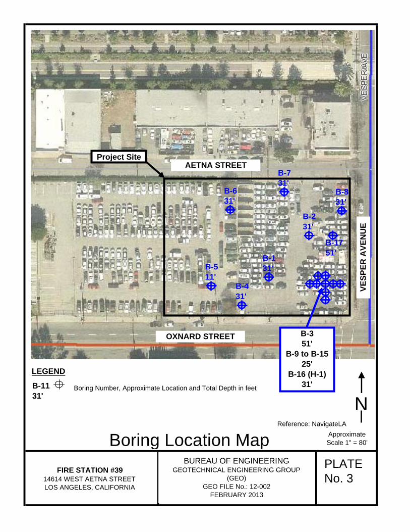
PLATE No. 3
ApproximateScale 1" = 80'Boring Location Map
NBoring Number, Approximate Location and Total Depth in feet
LEGEND
B-1131'
BUREAU OF ENGINEERINGGEOTECHNICAL ENGINEERING GROUP
(GEO)GEO FILE No.: 12-002
FEBRUARY 2013
FIRE STATION #3914614 WEST AETNA STREETLOS ANGELES, CALIFORNIA
Reference: NavigateLA
Project Site
B-511'
B-731'
B-831'
B-431'
B-631'
B-131'
B-231'
B-1751'
B-3 51'
B-9 to B-1525'
B-16 (H-1)31'
OXNARD STREET
VESP
ER A
VEN
UE
AETNA STREET

N
PLATE No. 4
REGIONAL GEOLOGY
Project Site
Reference: "Geologic Map of the Van Nuys Quadrangle," 2001 Thomas W. Dibblee Jr.
Approximate Scale 1" = 2,000'
BUREAU OF ENGINEERINGGEOTECHNICAL ENGINEERING GROUP
(GEO)GEO FILE No.: 12-002
FEBRUARY 2013
FIRE STATION #3914614 WEST AETNA STREETLOS ANGELES, CALIFORNIA

PLATE No. 5
SEISMIC HAZARD ZONES
Reference: "Official Map of Seismic Hazard Zones,"Van Nuys, February 1, 1998, California Department of Conservation, Division of Mines and Geology.
NApproximate
Scale 1" = 2,000'
Project Site
BUREAU OF ENGINEERINGGEOTECHNICAL ENGINEERING GROUP
(GEO)GEO FILE No.: 12-002
FEBRUARY 2013
FIRE STATION #3914614 WEST AETNA STREETLOS ANGELES, CALIFORNIA


Fire Station #39 February 15, 2013
APPENDIX A
Standards Report of Subsurface Investigation Dated May 15, 2012


FIRE STATION NO. 39 - REVISED LAB NO. 140-5896
FIRE STATION NO. 39 - PHASE II LAB NO. 140-5908
W.0 NO. E170094B MAY 2012
GEOTECHNICAL SERVICES FILE: 12-002

■ 13.. Nos.
IZEPIT'D
To
CITY Of LOS ANGELES
DEPARTMENT OF GENERAL SERVICES STANDARDS
140-5896 / 140-5908 2319 DORRIS PLACE LOS ANGELES, CA 90031
02-07-12 / 03-27-12 (213) 485-2242
02-09-12 / 04-06-12 fax (213) 485-5075
05-15-12 Gary Lee Moore City Engineer Att'n: Christopher Johnson
Fire Station # 39-Revised
Fire Station # 39 - Phasell
W.O. No. E170934B File No. 12-002
Report of SUBSURFACE INVESTIGATION
Transmitted are the results of subsurface investigation performed by Standards on the above-named project as requested by the Geotechnical Engineering Group (GEO) of the Bureau of Engineering. The logs of the test borings, the Unified Soil Classification and the results of the laboratory tests requested by the Engineer are parts of this report. The descriptions reported on the "Log of Test Boring" sheets are based on field identification procedures, examination of the samples in the laboratory and soil classification tests. The soil classification is based on the attached Unified Soils Classification System.
Fifteen test borings were drilled on this project with a truck-mounted Central Mine Equipment Model-75HT drill rig using 6-inch diameter conventional flight augers. "Undisturbed" samples were obtained from the test borings B-1 to B-8 at depths indicated on the log sheets with a 31/2-inch outside diameter (O.D.) by 3-inch inside diameter (I.D.) Split Spoon sampler lined with 2 7/8- inch inside diameter (I.D.) by 1-inch high brass tubes. The sampler was driven into the soil with the weight of a 300-pound automatic trip hammer falling approximately 30 inches. There was no sampling required from the test borings B-9 to B-15, drilling was performed for geotechnical n vesti gati on purposes.
Standard Penetration Test (SPT) ASTM D1586 was performed on test boring B-3 only. The SPT test involves penetration of soil around the tip of a Split Spoon sampler for a condition of constant energy transmittal. The Split Spoon, 2-inch outside diameter (O.D.) by 1 3/8-inch inside diameter (I.D.), is driven eighteen (18) inches. The sampler is seated in the first six (6) inches and the number of blows required to drive the sampler the last twelve (12) inches is recorded as the value SPT blow count. The driving energy is provided by a 140-pound automatic trip hammer dropped thirty (30) inches at depths indicated on the log sheets.
Percolation test was performed at boring location B-5 on 03-10-12. Standards Division personnel followed GEO's Infiltration Testing Procedure that was transmitted to Standards on 02-07-12.
The raw percolation test data sheets were faxed to GEO at the end of the test. GEO was responsible to review the data sheets and analyze the test results. Tabulated data sheets for the percolation test are attached to this report for informational purposes only.
Organic Vapor Analyzer (OVA) readings and Lower Explosive Limit (LEL) readings were taken during the drilling operation with a Photovac Inc. Model Microfid I/SC EXIA and RKI

!,ab. No. 140-5896 & 140-5908 Fire Station # 39-Revised Paw 2 of 3 & Fire Station #39- Ph II
W.O. No. E170094B File No. 12-002
Instruments Model Eagle devices. The OVA reading were taken 2-ft above the test-boring hole at intervals when the drilling operation reached each s olinpling depth. OVA readings were also taken in the bulk soil sample bags after soil collection. LEL reading were taken above the conventional flight augers prior to soil sampling.
The following tests were performed on samples from the test borings:
In-place Dry Density and Field Moisture (ASTM D2937)
Laboratory Maximum Dry Density and Optimum Moisture Content (ASTM D1557)
Consolidation (ASTM D2435)
Direct Shear (ASTM D3080)
Grain Size Analysis/Hydrometer (ASTM D422)
Liquid Limit (ASTM D4318 — one point method)
Plasticity Index (ASTM D4318)
Stabilometer "R" Value (California Test Method No. 301)
Chemical tests on distilled water extracts from soil samples were made as follows:
Sul fates EPA 300.0 Chlorides EPA 300.0
PH SM4500-H+B Conductivity EPA 120.1
Acidity SM2310B
Whenever possible, the in-place dry density and field moisture content were determined from the total undisturbed sample before being prepared for other laboratory tests. These are reported to the nearest 0.1 pound per cubic foot (nearest 1 pound per cubic foot on the log sheets) and 0.1 percent respectively.
Each consolidation test was performed on 2%-inch diameter by 1-inch one high undisturbed or remolded soil specimen in a floating ring type consolidometer. The specimen was retained in the 2%-inch I.D. brass ring during the test and porous disks were placed on the top and bottom of the specimen. The specimen was initially tested at field moisture to the normal load indicated on the data sheet. When the testing at field moisture was completed, sufficient water was added to cover the specimen and the consolidation test was continued with the specimen under water. At the conclusion of the test, the submerged specimen was allowed to rebound by decreasing the load in decrements shown on the data sheet, concluding with the normal load of 0.1 ton per square foot, and the corresponding rebound readings taken.
Each direct shear test was performed on 2%-inch diameter by 1-inch high undisturbed or remolded soil specimens that were soaked for at least 24 hours before being tested. During soaking the specimens were confined between two perforated brass plates to prevent swelling. The specimens were tested under various normal loads, with a different specimen being used for

ea (Er
H. SOLOM I A \rir General Services/Stand
1,ab. No. 140-5896 & 140-5908 Fire Station # 39-Revised Page 3 of 3 & Fire Station #39- Ph II
W.O. No. E170094B File No. 12-002
each normal load, while submerged in water. The rate of shearing is listed on the data sheet. Peak shear load values (represented by solid symbols) and ultimate shear load values at 0.250-inch displacement of the sheared specimens (represented by symbols which are not solid) are reported.
The R-Value test was performed on a composite sample in accordance with California Test Method No. 301. Three soil specimens with different moisture contents molded and tested at three different exudation pressures. The R-Value was obtained at the exudation pressure of 300 psi.
Geotechnical Engineering Group gave the Notice to Proceed with the subsurface investigation to Standards on 02-09-12 & 04-06-12. Benjamin Moore of your Bureau was notified at least 48 hours prior to the drilling and sampling operations. A boring location map is included in this report.
All soil samples for the above-named project that were delivered to the Standard Foundation Laboratory are presently being stored. These samples will be discarded 45 days after the date of this report unless a specific written request to retain the samples for additional testing or for a longer storage period is submitted by your Bureau.
RHS:JV:KSN:MNR:m


1/6
2/6
3/6
3/6
0
0
0
0
3/6
4/6 0
= 5/6
6/6 0 0
10/6
1,5/6 0
-- o
5
10
15
20
25
30
35
0
0
3/6
3/6
4/6
8/6
695
690
685
680 --
675
670
665
LOG OF TEST BORING LAB. NO.: 140- 5896 PROJECT: FIRE STATION NO. 39 - REVISED BORING NO.: B-1 ELEVATION: 698' MSL DRILLING DATE: 03/05/2012 BORING LOCATION: 71' N/o NCF Oxnard St & 133' W/o WCF Vesper Av DRILL RIG TYPE: CME-75HT using 6" diameter conventional flight augers DEPTH TO STANDING WATER: None DEPTH TO WATER SEEPAGE: None DRILLER: Cooksey LOGGER: Roth ENGINEER: None present
ELEVATION /
DEPTH (ft) _
SOIL SYMBOLS, SAMPLER SYMBOLS AND BLOWS/INCHES
LEL (%)
OVA (PPM) USCS Field Description Moist.
°A
D ry Dens.
Pcf
CL 2" AC pavement in poor condition.
6" PCC pavement. Brown lean clay with sand. Moist and soft. Bulk soil sample taken from 0 to 2 1/2' depth.
17.0 106
Density increased slightly at 5' depth. 14.9 108
Encountered some clay binder at 10' dpeth. 20.6 102
14.7 118
S M Silty sand
No free water ---
Test boring Location Coordinates: 34° 10' 46.83" N
118° 27' 05.02" W
660
CITY OF LOS ANGELES - STANDARDS DIVISION
14.7 119
19.6 107
10.1 128
4
1/6
2/6
2/6
3/6
3 / 6
4/6
3/6
5 / 6
5 /6
8 / 6
6/6
8 / 6
0 11/6
20/6 133
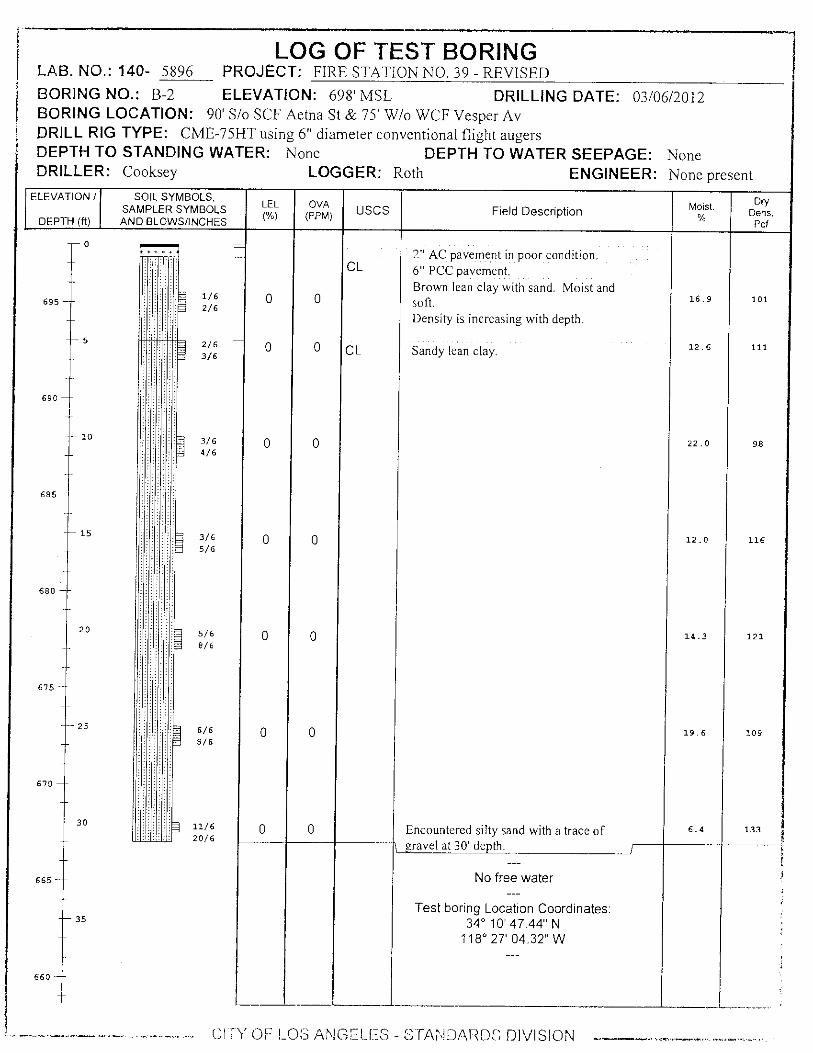
LOG OF TEST BORING LAB. NO.: 140- 5896 PROJECT: FIRE STATION NO. 39 - REVISED
BORING NO.: B-2 ELEVATION: 698' MSL DRILLING DATE: 03/06/2012 BORING LOCATION: 90' S/o SCF Aetna St & 75' W/o WCF Vesper Av DRILL RIG TYPE: CME-75HT using 6" diameter conventional flight augers DEPTH TO STANDING WATER: None DEPTH TO WATER SEEPAGE: None DRILLER: Cooksey LOGGER: Roth ENGINEER: None present
ELEVATION /
DEPTH (ft)
SOIL SYMBOLS, SAMPLER SYMBOLS AND BLOWS/INCHES
LEL
(%)
OVA (PPM) USCS Field Description Moist.
%
Dry D ens.
Pcf
I
0 + + +
695
5
690
10
685
15
680
20
675
25
670
30
665
35
660
CL 2" AC pavement in poor condition. 6" PCC pavement. Brown lean clay with sand. Moist and
0 soft. 16.9
Density is increasing with depth.
0 CL Sandy lean clay. 12.6
22.0
12.0
0 14.3
0 19.6
0 Encountered silty sand with a trace of 6.4
\ gravel at 30' depth.
No free water
Test boring Location Coordinates: 34° 10' 47.44" N
118° 27' 04.32" W
0
0
0
0
0
0
0
CITY OF LOS ANGELES - STANDARDS DIVISION --

LOG OF TEST BORING LAB NO. : 140- 5896 PROJECT: FIRE STATION NO. 39 - REVISED BORING NO.: B-3 ELEVATION: 698' MSL DRILLING DATE: 03/07/2012 BORING LOCATION: 56' N/o NCF Oxnard. St & 50' W/o WCF Vesper Av DRILL RIG TYPE: CME-75HT using 6" diameter conventional flight augers DEPTH TO STANDING WATER: None DEPTH TO WATER SEEPAGE: None DRILLER: Cooksey LOGGER: Roth ENGINEER: None present
ELEVATION / SOIL SYMBOLS,
SAMPLER SYMBOLS USCS Field Description Standard Penetration
Readings DEPTH (ft) AND BLOWS/FOOT 1st 6" 2nd 6" 3rd 6"
0
2" AC pavement in poor condition. 6" PCC pavement. SM
695
5
690
10
CL
685
15
SM
668
20
675
25
SM
30
FILL MATERIAL (possibly backfilled excavation Brown silty fine-very fine sand. Moist and soft. Field Moisture = 12% @ 2.5' depth.
Field Moisture = 10.7% @ 5' depth.
Lean clay Field Moisture = 16.4% @ 10' depth.
Silty sand. Field Moisture = 11.3% @ 15' depth. Encountered red clay bricks/brick fragments from 15' to 22' depth.
Field Moisture = 9% @ 20' depth.
Field Moisture = 12.8% @ 25' depth.
Grayish brown silty fine-medium sand with a trace of gravel. Moist and dense.
Medium sand content decreased at 30' depth; Field Moisture = 10% @ 30' depth.
1 2 2
4 5 5
3 3 4
4 3 3
3 4
1 1 1
4 9 12
665
CL-ML Sandy silty clay Field Moisture = 11.6% @ 35' depth.
8 9 10
CITY OF LOS ANGELES - STANDARDS DIVISION

620
75
625
70
630
635
65
LOG OF TEST BORING LAB NU.: 140- 5896 PROJECT: FIRE STATION NO. 39 - REVISED BORING NO.: B-3 ELEVATION: 698' MSL DRILLING DATE: 03/07/2012 BORING LOCATION: 56' N/o NCF Oxnard St & 50' W/o WCF Vesper Av DRILL RIG TYPE: CME-75I-IT using 6" diameter conventional flight augers DEPTH TO STANDING WATER: None DEPTH TO WATER SEEPAGE: None DRILLER: Cooksey LOGGER: Roth ENGINEER: None present
ELEVATION / SOIL SYMBOLS,
SAMPLER SYMBOLS USCS Field Description Standard Penetration
Readings DEPTH MI_ AND BLOWS/FOOT 1st 6" 2nd 6" 3rd 6"
650
655
50
45
40 Sandy silty clay Sand content increased from 40' depth; Field Moisture = 9.7%.
Silt content decreased at 45' depth; Field Moisture = 6.3%.
Field Moisture = 15.9% @ '50 depth.
No free water
8 9 11
16 16 22
6 10 14
645
55
640
Test boring Location Coordinates: 34° 10' 46.47" N
118° 27' 04.03" W
LEL reading = 0% & OVA reading = 0
ppm at all depths. 60
CITY OF LOS ANGELES - STANDARDS DIVISION • • • ■•

Lean clay with sand. Encountered some clay binder at 10' depth.
10 5 / 6
7 / 6 0 0 CL 17.0
95
Encountered silty fine sand at 30' depth. 30
9 / 6
0
0 12/6
10.8
124
LOG OF TEST BORING LAB. NO.: 140- 5896 PROJECT: FIRE STATION NO. 39 - REVISED
BORING NO.: B-4 ELEVATION: 698' MSL DRILLING DATE: 03/01/2012 BORING LOCATION: 21' N/o NCF Oxnard St & 159' W/o WCF Vesper Av DRILL RIG TYPE: CME-75HT using 6" diameter conventional flight augers DEPTH TO STANDING WATER: None DEPTI+TO WATER SEEPAGE: None DRILLER: Cooksey LOGGER: Roth ENGINEER: None present
ELEVATION /
DEPTH (ft)
SOIL SYMBOLS, SAMPLER SYMBOLS AND BLOWS/INCHES
LEL
(%)
OVA (PPM)
USCS Field Description Moist. Dry
Dens.
Pcf
0
2 / 6
3/6
ML 2" AC pavement in poor condition. .6" PCC pavement. Brown silt with some fine-very fine sand. Moist and soft.
695
0 0
9.9 94
5 4/6 0 0
11.9 107
690
4 / 6
685
15
3 / 6
0
0
10.8
113 4/6
680
CL
Brown lean clay with sand. Moist and firm.
20
7 / 6
0
0
13.1
120 13/6
25
5 / 6
0
0
16.9
109 6/6
No free water ---
Test boring Location Coordinates:
35
34° 10' 46.34" N 118° 27' 05.31" W
CITY OF LOS ANGELES - STANDARDS DIVISION

5
10
15
20
25
LOG OF WELL INSTALLATION LAB NO.:140- 5896 PROJECT: FIRE STATION NO. 39 - REVISED BORING NO.: B-5 ELEV.: 698' MSL DATE: 03/01/2012 BORING LOCATION: 58' N/o NCF Oxnard St & 207' W/o WCF Vesper Av DRILL RIG TYPE: CME-75HT using 6" diameter conventional flight augers DRILLER: Cooksey LOGGER: Roth ENGINEER: None present DEPTH TO WATER: None DEPTH TO WATER SEEPAGE: None
ELEVATION / WELL USCS
SOIL SYMBOLS, SAMPLER SYMBOLS AND BLOWS/INCHES
Field Description DEPTH (ft) DETAILS
- 0
CL
S M 2" AC pavement in poor condition 6" Base material. Brown silty fine-very fine sand. Moist and soft. IPD =106 lbs/ft 3 & Field Moisture = 12% @ 2.5' depth.
Lean clay with sand. IPD =109.5 lbs/ft 3 & Field Moisture =15.32% @ 5' depth; density increased slightly; only 5 SP rings were retained.
IPD =106 lbs/ft 3 & Field Moisture = 18.7% ..t) 10' depth.
695
690
685
680 -
No free water ---
Test boring Location Coordinates: 34° 10' 46.69" N
118° 27' 05.90" W
A 4" diameter PVC percolation test well removed on 3/6/12. Test hole redrilled with 9" diameter flights. A new 4" diameter percolation test
well installed to a depth of 10' (5' slotted pie, 5 solid pipe). Well backfilled with # 3 sand to 4' below surface grade. A bucket of
bentonite pellets & water was added on top of #3 sand . Bentonite powder, sand & soil dry mixed and added on top of pellets (layered
with water to surface grade.
675 --
670 -
30
665 .-
35
660 -
A
1 •
CITY OF LOS ANGELES STANDARDS DIVISION ---

ii
1/6
2/6
3/6
4/6
4/6
5/6
4/6
5/6
4/6
8/6
4/6
7/6
5/6
716
LOG OF TEST BORING LAB. NO.: 140- 5896 PROJECT: FIRE STATION NO. 39 - REVISED
BORING NO.: B-6 ELEVATION: 699' MSL DRILLING DATE: 03/01/2012 BORING LOCATION: 52' S/o SCF Aetna St & 186' W/o WCF Vesper Av DRILL RIG TYPE: CME-75HT using 6" diameter conventional flight augers DEPTH TO STANDING WATER: None DEPTH TO WATER SEEPAGE: None DRILLER: Cooksey LOGGER: Roth ENGINEER: None present
SOIL SYMBOLS, SAMPLER SYMBOLS AND BLOWS/INCHES
LEL (%)
OVA (PPM)
SM
USCS -LEVATION /
DEPTH (ft)
0
695
5
690
10
685
15
20
67 5
25
670
30
665
35
660
Moist. Dry Dens.
Pcf
16.0 108
12.8 110
17.5 105
7.1 117
13.7 119
19.8 105
16.4 114
0
0
0
0
0
0
0
0
0
0
0
0
Field Description
2" AC pavement in poor condition. 6" PCC pavement. Brown silty fine-very fine sand. Moist and soft.
Density increased slightly @ 5' depth.
Silty sand. Encountered a 1' silty sand lense at 15.5' depth.
No free water ---
Test boring Location Coordinates: 34° 10' 47.81" N
118° 27' 05.64" W
CITY OF LOS ANGELES - STANDARDS DIVISION

LOG OF TEST BORING LAB. NO.: 140- 5896 PROJECT: FIRE STATION NO. 39 - REVISED BORING NO.: B-7 ELEVATION: 698' MSL DRILLING DATE: 03/06/2012 BORING LOCATION: 30' S/o SCF Aetna St & 106' W/o WCF Vesper Av DRILL RIG TYPE: CME-75HT using 6" diameter conventional flight augers DEPTH TO STANDING WATER: None DEPTH TO WATER SEEPAGE: None DRILLER: Cooksey LOGGER: Roth ENGINEER: None present
ELEVATION /
DEPTH (ft)
SOIL SYMBOLS, SAMPLER SYMBOLS AND BLOWS/INCHES
LEL (%)
OVA (PPM) USCS Field Description moist.
% Dry
Dens. Pcf
I
0
SM
CL
2" AC pavement in poor condition 8" Base material. Brown silty fine-very fine sand. Moist and firm.
Sandy lean clay
17.5
14.0
104
107
Encountered some clay binder at 10' depth. 21.6 100
16.3 108
Sand content increased at 20' depth with iron oxide staining.
13.3 123
675
695
690
685
680
2/6
2/6
3/6
3/6
3/6
5/6
3/6
4/6
5/6
8/6
5/6
5
10
15
20
25 20.6
10.0
0
0
0
0
0
0
0
108
127
0
0
0
0
0
0
7/6
670
Encountered a trace of gravel at 30' depth.
No free water
Test boring Location Coordinates: 34° 10' 46.83" N
118° 27' 05.02" W
660
CITY OF LOS ANGELES - STANDARDS DIVISION
30
665
35
13/6
7/6

LOG OF TEST BORING LAB. NO.: 140- 5896 PROJECT: FIRE STATION NO. 39 - REVISED BORING NO.: B-8 ELEVATION: 698' MSL DRILLING DATE: 03/05/2012 BORING LOCATION: 51' S/o SCF Aetna St & 22' W/o WCF Vesper Av DRILL RIG TYPE: CME-75HT using 6" diameter conventional flight augers. DEPTH TO STANDING WATER: None DEPTH TO WATER SEEPAGE: None DRILLER: Cooksey LOGGER: Roth ENGINEER: None present
ELEVATION /
DEPTH (ft)
SOIL SYMBOLS, SAMPLER SYMBOLS AND BLOWS/INCHES
LEL
(%)
OVA (PPM) USCS Field Description Moist.
%
Dry De ns.
Pcf
I
CL
ML
SP/SM
695
0
0 0 :•-•••:•=-• -
2/6
3/6
5 4/6 0 0 4/6
690
0 0 10 5/6
7/ 6
685
15 6/6 0 7/6
680
20 12/6 0 0 26/6
675
25 7/6 0 0 11/6
670
30 10/6 0 0 13/6
665
35
660
2" AC pavement in poor condition 3" Base material. Light brown poorly graded fine sand with
some silt. Moist and soft. 13.6 97
Brown silt with some fine-very fine sand. Moist and firm.
Only 5 SP rings were retained at 5' depth. 10.6 103
Lean clay. 13.4 92
13.4 101
Encountered a 2' clayey silt lense at 20' depth.
7.7 116
14.5 112
Encountered a trace of gravel at 30' depth. 11.5 122
No free water ---
Test boring Location Coordinates: 34° 10' 46.83'N
118° 27' 05.02" W
CITY OF LOS ANGELES - STANDARDS DIVISION ------

665
35
^1-
660
LOG OF TEST BORING LAB. Na: 140- 5908 PROJECT: FIRE STATION NO. 39 - Phase II BORING NO.: B-9 ELEVATION: 699' MSL DRILLING DATE: 04/20/2012 BORING LOCATION: 56' N/o NCF Oxnard St & 60' W/o WCF Vesper Av DRILL RIG TYPE: CME-75HT using 6" diameter conventional flight augers DEPTH TO STANDING WATER: None DEPTH TO WATER SEEPAGE: None DRILLER: Cooksey LOGGER: Roth ENGINEER: None present
ELEVATION /
DEPTH (ft)
SOIL SYMBOLS, SAMPLER SYMBOLS AND BLOWS/INCHES
USCS Field Description Moist. °A
Dens. Pcf
670
30
685
15
680 -
20
675
25
695 -
5
690
10
0
For geotechnical investigation purposes; no sampling required.
For lithogy, refer to Boring Log "B-3" located 10' to the East.
--- No fill debris encountered at this location.
CITY OF LOS ANGELES - STANOARDS DIVISION
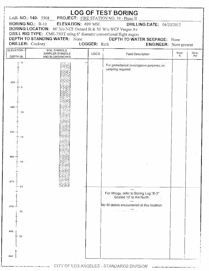
LOG OF TEST BORING LAB. NO.: '140- 5908 PROJECT: FIRE STATION NO. 39 - Phase II BORING NO.: B-10 ELEVATION: 699' MSL DRILLING DATE: 04/20/2012 BORING LOCATION: 46' N/o NCF Oxnard St & 50' W/o WCF Vesper Av DRILL RIG TYPE: CME-75HT using 6" diameter conventional flight augers DEPTH TO STANDING WATER: None DEPTH TO WATER SEEPAGE: None DRILLER: Cooksey LOGGER: Roth ENGINEER: None present
ELEVATION /
DEPTH (ft) SAMPLER SYMBOLS AND BLOWS/INCHES
USCS SOIL SYMBOLS.
Field Description Moist. °A
Dens. Pcf
-0
695
5
690
10
685 ---
-- 15
680
20
675
-- 25
670
30
665
35
660 -
For geotechnical investigation purposes; no sampling required.
No fill debris encountered at this location.
For lithogy, refer to Boring Log "B-3" located 10' to the North.
‘. CITY OF LOS ANGELES -- STANDARDS DIVISION ---------
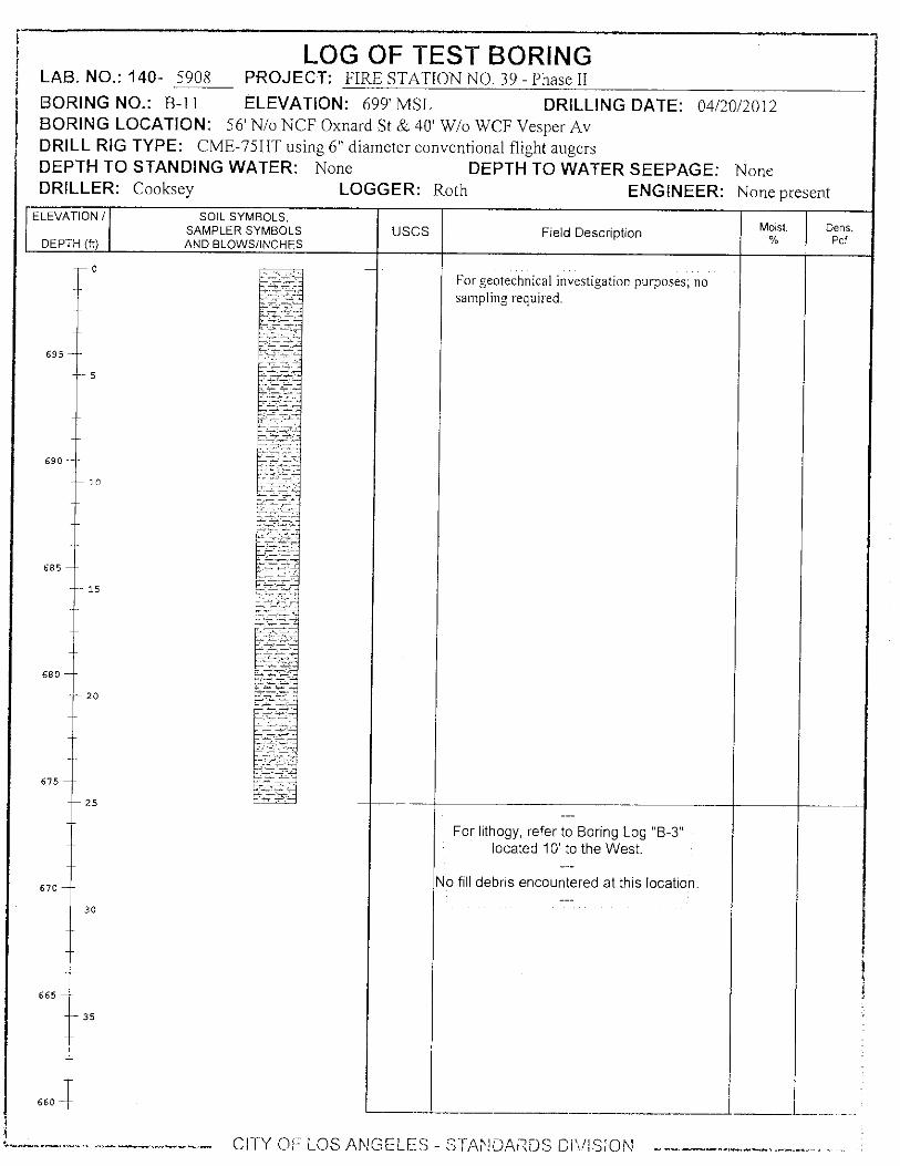
LOG OF TEST BORING LAB. NO.: 140- 5908 PROJECT: FIRE STATION NO. 39 - Phase II
BORING NO.: B - 11 ELEVATION: 699' MSL DRILLING DATE: 04/2Q/2012 BORING LOCATION: 56' N/o NCF Oxnard St & 40' W/o WCF Vesper Av DRILL RIG TYPE: CME-75HT using 6" diameter conventional flight augers DEPTH TO STANDING WATER: None DEPTH TO WATER SEEPAGE: None DRILLER: Cooksey LOGGER: Roth ENGINEER: None present
ELEVATION / SOIL SYMBOLS, SAMPLER SYMBOLS USCS Field Description Moist. Dens.
DEPTH (ft) AND BLOWS/INCHES Pcf
0
For geotechnical investigation purposes; no sampling required.
695
5
690
10
15
20
25
For lithogy, refer to Boring Log "B-3" located 10' to the West.
--- No fill debris encountered at this location.
30
35
CITY OF LOS ANGELES - STANDARDS DIVISION ------------

LOG OF TEST BORING LAB. Nb.: 140- 5908 PROJECT: FIRE STATION NO. 39 - Phase II BORING NO.: B-12 ELEVATION: 699' MSL DRILLING DATE: 04/20/2012 BORING LOCATION: 61' N/o NCF Oxnard St & 50' W/o WCF Vesper Av DRILL RIG TYPE: CME-75HT using 6" diameter conventional flight augers DEPTH TO STANDING WATER: None DEPTH TO WATER SEEPAGE: None DRILLER: Cooksey LOGGER: Roth ENGINEER: None present
ELEVATION /
DEPTH (ft)
SOIL SYMBOLS, SAMPLER SYMBOLS AND BLOWS/INCHES
USCS Field Descripti on M Moist. %
Dens. Pcf
0
For geotechnical investigation purposes; no sampling required.
5
10
15
20
25
For lithogy, refer to Boring Log "B-3" located 5' to the South.
No fill debris encountered at this location.
30
35
CITY OF LOS ANGELES - STANDARDS DIVISION ----

LAB. NO.: 140- 5908 LOG OF TEST BORING
PROJECT: FIRE STATION NO. 39 - Phase II
BORING NO.: B-13 ELEVATION: 699' MSL DRILLING DATE: 04/20/2012 BORING LOCATION: 46' N/o NCF Oxnard St & 50' W/o WCF Vesper Av DRILL RIG TYPE: CME-75HT using 6" diameter conventional flight augers DEPTH TO STANDING WATER: None DEPTH TO WATER SEEPAGE: None DRILLER: Cooksey LOGGER: Roth ENGINEER: None present
ELEVATION / SOIL SYMBOLS, SAMPLER SYMBOLS USCS Field Description Moist. Dens.
DEPTH (ft) AND BLOWS/INCHES % Pcf
0 2" AC pavement in fair condition. 9" PCC pavement.
Encountered a void from 32" to 54" on East wall of boring.
5
695
- 10
690
Augers did not produce soil cuttings between 10' & 20' depths.
685
15
680
20
Encountered red clay brick fragments from 22' to 25' depth.
675
670 -
665
660
25
30
35
CI 1Y OF LOo ANGELES -- STANDARDS DIVISION

LAB. NO.: 140- 5908 LOG OF TEST BORING
PROJECT: FIRE STATION NO. 39 - Phase II
BORING NO.: B-14 ELEVATION: 699' MSL DRILLING DATE: 04/20/2012 BORING LOCATION: 53' N/o NCF Oxnard St & 50' W/o WCF Vesper Av DRILL RIG TYPE: CME-75HT using 6" diameter conventional flight augers DEPTH TO STANDING WATER: None DEPTH TO WATER SEEPAGE: None DRILLER: Cooksey LOGGER: Roth ENGINEER: None present
ELEVATION / SOIL SYMBOLS, SAMPLER SYMBOLS USCS Field Description Moist. Dens.
DEPTH (ft) AND BLOWS/INCHES % Pcf
0
For geotechnical investigation purposes; no sampling required.
695
5
690
10
685
15
680
20
675
25
For lithogy, refer to Boring Log "B-3" located 3' to the North.
No fill debris encountered at this location.
30
665
35
660 -
670
-1-
---- CITY OF LOS ANGELES - STANDARDS DIVISION

LOG OF TEST BORING LAB. Nb.: 140- 5908 PROJECT: FIRE STATION NO. 39 - Phase II BORING NO.: B-15 ELEVATION: 699' MSL DRILLING DATE: 04/20/2012 BORING LOCATION: 56' N/o NCF Oxnard St & 47' W/o WCF Vesper Av DRILL RIG TYPE: CME-75HT using 6" diameter conventional flight augers DEPTH TO STANDING WATER: None DEPTH TO WATER SEEPAGE: None DRILLER: Cooksey LOGGER: Roth ENGINEER: None present
ELEVATION /
DEPTH (ft)
SOIL SYMBOLS, SAMPLER SYMBOLS AND BLOWS/INCHES
USCS Field Description Moist. %
Dens. Pcf
0
For geotechnical investigation purposes; no sampling required.
695
5
690
10
685
15
680
20
675
25
For lithogy, refer to Boring Log "B-3" located 3' to the West.
No fill debris encountered at this location.
-- 30
665
35
660
CITY OF LOS ANGELES - STANDARDS DIVISION
670
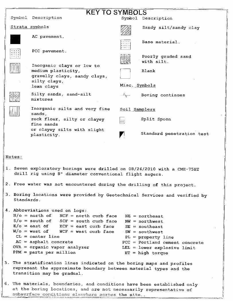
Split Spoon
Inorganic silts and very fine Soil Samplers sands, rock flour, silty or clayey fine sands or clayey silts with slight plasticity. Standard penetration test
Symbol Description Symbol Description
Strata symbols
AC pavement.
Sandy silt/sandy clay
Base material.
Poorly graded sand with silt.
PCC pavement.
Blank
Misc. Symbols
Boring continues
Inorganic clays or low to medium plasticity, gravelly clays, sandy clays, silty clays, lean clays
Silty sands, sand-silt mixtures
KEY TO SYMBOLS
Notes:
1. Seven exploratory borings were drilled on 08/24/2010 with a CME-75HT drill rig using 8" diameter conventional flight augers.
2. Free water was not encountered during the drilling of this project.
3. Boring locations were provided by Geotechnical Services and verified by Standards.
4. Abbreviations used on logs:.
5. The stratification lines indicated on the boring maps and profiles represent the approximate boundary between material types and the transition may be gradual.
6. The materials, boundaries, and conditions have been established only at the boring locations, and are not necessarily representative of subsurface conditions elsewhere across the site
north curb face south curb face east curb face
curb
concrete limit
NE NW SE
face SW PL
PCC LEL HT
N/o = north of NCF = S/o = south of .SCF = E/o = east Of ECF = W/o = west of WCF = west CL = center line AC = asphalt concrete OVA = organic vapor analyzer. PPM = parts per million
= northeast = northwest = southeast = southwest = property line = Portland cement = lower explosive = high torque

KEY TO SYMBOLS Symbol Description
Monitor Well Details
silica sand, blank PVC
bentonite pellets
slotted pipe w/ sand
silica sand, no pipe (end plug)
-.--
. • .'
,7-EE
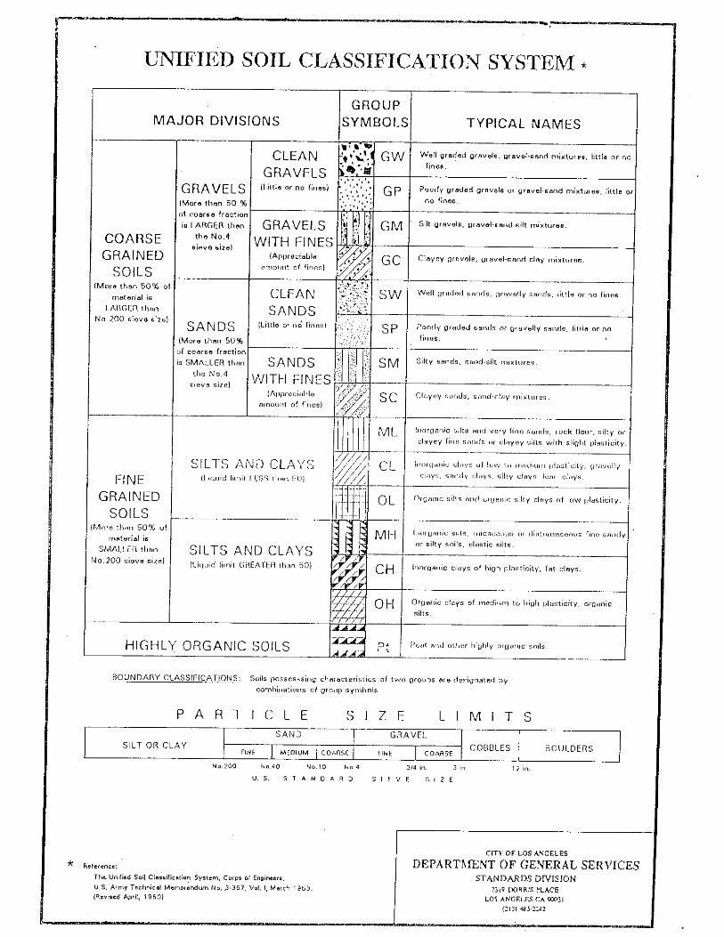
SIZE LIMITS PARTICLE
12 in. No.200 3/4 in. 3 in. No.40 No.10 No.4
irdammivar.014,11,10..11119
UNIFIED SOIL CLASSIFICATION SYSTEM *
• MAJOR DIVISIONS
GROUP SYMBOLS TYPICAL NAMES
COARSE GRAINED
SOILS (More than 50% of
material is
LARGER than
No.200 sieve size)
G RAVELS
(More than 50 %
of coarse fraction
is LARGER than the No.4
sieve size)
CLEAN -'s ,. .::4 11
GRAVELS (Little or no fines)
A
.--
%Clew , •
481 4 ' 0
GW Well graded gravels, gravel-sand mixtures, little or no
fines.
, .
'
no fines.
G P '
Poorly graded gravels or gravel-sand mixtures, little or
GRAVELS WITH FINES
(Appreciable
amount of fines)
• .
. Gm - Silt gravels, gravel-sand-silt mixtures.
•'•
•
11
GC '
Clayey gravels, gravel-sand-clay mixtures.
SANDS (More than 50%
of coarse fraction
is SMALLER than
she No.4
ieve size)
CLEAN SANDS
(Little or no fines)
•
.
.•-• SW wen o r.-led ,,,.(18, gravelly sands, little or no fines.
•
fines.
Sp Poorly graded sands or gravelly sands, little or no
SANDS WITH FINES
(Appr ecial de
amount of fines)
• sm Silty sands, sand-silt mixtures.
. .'..,Y ' ' SC Clayey sands, rand-clay mixtures.
FINE GRAINED
SOILS (More than 50% of
material is
SMALLER than
No.200 sieve size)
SILTS AND CLAY S (Liquid lirnit LESS than 5 0 )
mi_. Inorganic silts and very fine sands, rock flour, silty or
clayey fine sands or clayey silts with slight plasticity.
////
/ ' / , (----L
//////.. // \ --/ / /
-
inorganic clays of low to modiurn i,lastioity, gravelly
clays, sandy clays, silty clays, lean clays.
OL Organic silts and organic silty clays of low plasticity.
SILTS AND CLAYS (Liquid limit GREAT-ER than 50)
'
7 Ili' Ili
k ti mH Ili
i
Inorganic silts, micaceous or diatomaceous fine sandy
or silty soils, elastic silts.
' / /
// / CH / / / /
'4
Inorganic clays of high plasticity, fat clays.
Organic clays of medium to high plasticity, organic
silts. Ar OH
HIGHLY ORGANIC SOILS .--4--- Peat and other highly organic soils. Pt
BOUNDARY CLASSIFICATIONS: Soils possesssing characteristics of two groups are designated by
combinations of group symbols.
SILT OR CLAY SAND GRAVEL ,
COBBLES I BOULDERS FINE MEDIUM COARSE '
FINE COARSE
U.S. STANDARD SIEVE SIZE
Reference:
The_ Unified Soil Classification System, Corps of Engineers,
U.S. Army Technical Memorandum No..3-367, Vol. I, March 196:5.
(Revised April, 1960)
raumpoicelliiememosamprimemar. L
CITY OF LOS ANGELES
DEPARTMENT OF GENERAL SERVICES STANDARDS DIVISION
2319 DORRIS PLACE
LOS ANGELES CA 90031 (213) 485-2242

C)oo,
c) E.
co
0
D
5 a
C/D
- _
- - s.%-\
_ _ - -
- \ _\ — \ —
0 d',..,- 0
\ 7,
0
_ _
_
— \
\ ,
_ _ _
\)>A _\ . 4./ \ Z \ ..2 \
F0
_ \ ‘t) \ \ \ \
-L,
\ \
\is
of "
A" L
ine
= 0.
73 (
ILL
-
o f L
ine:
= 0.
90 ( L
L
r %.„
I ilt
•
I II I 1 1 ii
0
PLASTICITY INDEX (PI)

ASTM D1557: MOISTURE-DENSITY TEST 124
122
120 4C)" a >, in E a) p ,?_ 0
1 18
116
114
I
,
- II -
T- I. I t
I ,
. I,
i
_1
_
,
1
,
ZAV for Sp.G. = 2
1
,
,_
.
f -1 - ' f-
I T
-t
[-
-
I
- '-
,_
—
2.7
_4 -r
8 10 12 14 16 18 20 Water content, °A)
Test specification: ASTM D 1557 Procedure B Modified
Elev/
Depth
Classification Nat.
Moist. Sp.G. LL PI
% >
3/8 in.
% <
No.200 USCS AASHTO
0 - 2.5' 2.7
TEST RESULTS MATERIAL DESCRIPTION
Maxi mum dry density = 120.1 pcf
Optimum moisture = 13.2 %
Lean Clay with Sand
Project No. E170094B Client: GEO/PW
Project: FIRE STATION No. 39
• Source: Sample No.: B-1 Elev./Depth: 0 - 2.5'
Remarks:
Date Sampled: 3-05-2012
Figure 1
ASTM D1557: MOISTURE-DENSITY TEST
CITY OF LOS ANGELES - STANDARDS DIVISION

ASTM D1557: MOISTURE-DENSITY TEST 12
12
116
114
, ,
,
----
1
1
I
1
I I , L
•
4
t
,
1
f.
4 , 6 8 10 12 14 1A 1 sl
AV for p.G. = .65
I
Water content, %
Test specification: ASTM D 1557 Procedure B Modified
Classification
USCS AASHTO Sp.G. LL PI
Elev/
Depth Nat.
Moist. % >
3/8 in.
% <
No.200
0 - 2.5' 2.65
MATERIAL DESCRIPTION TEST RESULTS
Silty Clayey Sand
Project No. E170094B Client: GEO/PW Project: FIRE STATION No. 39
• Source: Sample No.: B-3 Elev./Depth: 0 - 2.5'
ASTM D1557: MOISTURE-DENSITY TEST
CITY OF LOS ANGELES - STANDARDS DIVISION
Remarks:
Sample Date: 3-07-2012
Figure 1
Maximum dry density = 122.4 pcf
Optimum moisture = 11.8 %

Loa
d (T
ons /
Sq
uare
Foo
t)
Lab.'No. 140-5896
City of Los Angeles
Page 1 of 2 Department of General Services
Standards Divison
CONSOLIDATION DIAGRAM
Job Title: FIRE STATION NO. 39 - REVISED
W.O. NO.:
E170094B
BORING No.
DEPTH (Feet)
LOAD WATER ADDED (Tons per Square Foot)
IN-PLACE DRY DENSITY (Pounds per Cubic Foot)
MOISTURE
START END
B-3 0-2.5 1 110.1 11.8% 14.6%
Consolidation (%) Remolded to 95% RC
589E, [email protected],CHART
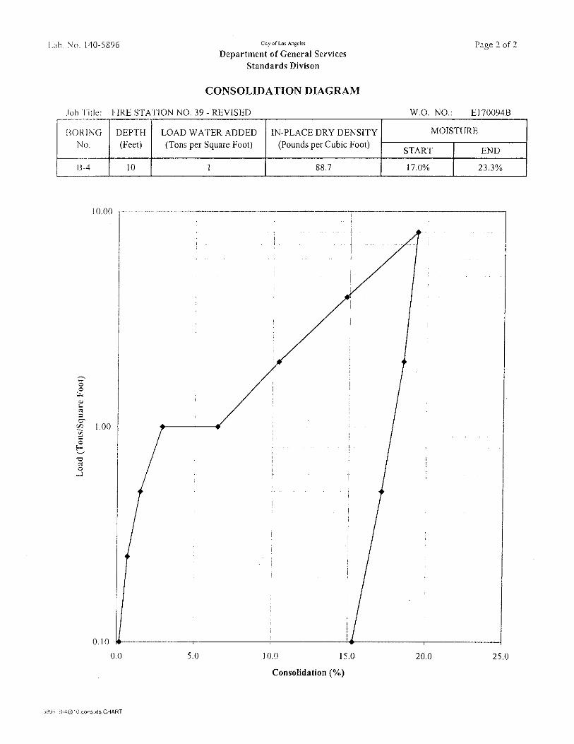
Loa d
(T
ons/
Squa
re F
oot)
Lib. No. H0-5896
City of Los Angeles
Page 2 of 2 Department of General Services
Standards Divison
CONSOLIDATION DIAGRAM
o b Title: FIRE STATION NO. 39 - REVISED
W.O. NO.:
E170094B
BORING No.
DEPTH (Feet)
LOAD WATER ADDED (Tons per Square Foot)
IN-PLACE DRY DENSITY (Pounds per Cubic Foot)
MOISTURE
START END
B-4 10 1 88.7 17.0% 23.3%
Consolidation (%)
5896 B-4(t10.cons.xls,CHART

SHEAR TEST RESULTS
legend:
NORMAL PEAK SHEAR FINAL SHEAR
STRESS, KSF STRESS, KSF STRESS, KSF
1 0.92 0.91
2 1.57 1.52
4 2.73 2.71
C= 0.34 ksf 0.31 ksf
TAN CP = 0.60 0.60
CP = 31.0° 30.9°
CITY OF LOS ANGELES DEPARTMENT OF GENERAL SERVICES
STANDARDS DIVISION, SOILS TESTING LAB
2319 DORRIS PLACE, LOS ANGELES, CA 90031
(213) 485-2242
DIRECT SHEAR TEST REPORT (ASTM D 3080)
Project No.: 140-5896
WO No.: E170094B
Project Title: FIRE STATION NO. 39 - REVISED
Boring No.: B-1
Depth, feet: 0-2.5
Date Sampled: 3/5/2012
Diameter, in: 2.847
Soil Description: Brown silt with some fine-very fine sand.
Disp. Rate, in/min: 0.01
Dry Density, PCF: 114.5
Initial Moisture, %: 1 3.2%
Final Moisture, °A: 20.0%
Test By: mnr
Remarks: Remold to 95% RC
120.1 pcf @ 13.2% MC (LAB MAX)
5.00
4.00
SH
EA
R S
TR
ES
S (
KSF
) 3.00
2.00
1.00
0.00
0
2 3 4 5
NORMAL STRESS (KSF)

SHEAR TEST RESULTS
NORMAL PEAK SHEAR FINAL SHEAR
STRESS, KSF STRESS, KSF STRESS, KSF
1 0.92 0.91
2 1.57 1.52
4 2.73 2.71
C= 0.34 ksf 0.31 ksf
TANS= 0.60 0.60
(i) = 31.0° 30.9°
SH
EA
R S
TRE
SS
(KS
F)
1.0 KSF
2.0 KSF
4.0 KSF
CITY OF LOS ANGELES DEPARTMENT OF GENERAL SERVICES
STANDARDS DIVISION, SOILS TESTING LAB
2319 DORRIS PLACE, LOS ANGELES, CA 90031
(213) 485-2242
DIRECT SHEAR TEST REPORT (ASTM D 3080)
Project No.: 140-5896
WO No.: E170094B
Project Title: FIRE STATION NO. 39 - REVISED
Boring No.: B-1
Depth, feet: 0-2.5
Date Sampled: 3/5/2012
Diameter, in: 2.847
Soil Description: Brown silt with some fine-very fine sand.
Disp. Rate, in/min: 0.01
Dry Density, PCF: 114.5
Initial Moisture, %: 13.2%
Final Moisture, 0/0: 20.0%
Test By: mnr
Remarks: Remold to 95% RC
120.1 pcf @ 13.2% MC (LAB MAX)
3000
SHEAR DISPLACEMENT (IN)

SHEAR TEST RESULTS
legend:
NORMAL PEAK SHEAR FINAL SHEAR
STRESS, KSF STRESS, KSF STRESS, KSF
1 0.84 0.82
2 1.54 1.51
4 3.09 3.00
C= 0.07 ksf 0.07 ksf
TANS= 0.75 0.73
(1) = 37.0° 36.2°
Disp. Rate, in/min: 0.004
Dry Density, PCF: 1 10.7
Initial Moisture, %: 1 2.6%
Final Moisture, %: 1 6.8%
Test By: mnr
Remarks:
Project No.: 1 40-5896
WO No.: El 70094B
Project Title: FIRE STATION NO. 39 - REVISED
Boring No.: B-2
Depth, feet: 5
Date Sampled: 3/6/2012
Diameter, in: 2.847
Soil Description: Brown sandy lean clay
CITY OF LOS ANGELES DEPARTMENT OF GENERAL SERVICES
STANDARDS DIVISION, SOILS TESTING LAB
2319 DORRIS PLACE, LOS ANGELES, CA 90031
(213) 485-2242
DIRECT SHEAR TEST REPORT (ASTM D 3080)
5.00
4.00
SH
EA
R S
TRE
SS
(KS
F)
3.00
2.00
/6'
1.00
0.00 •
2 3 4 5
NORMAL STRESS (KSF)
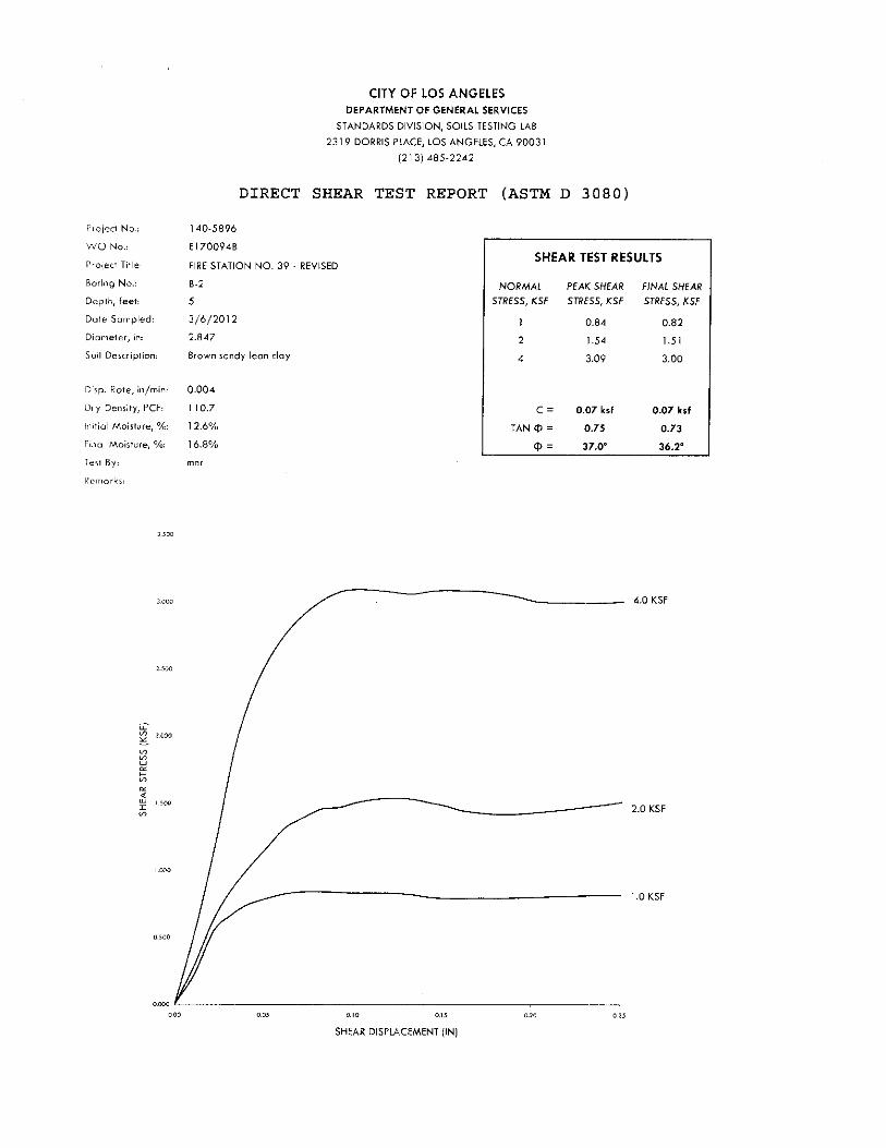
SHEAR TEST RESULTS
NORMAL PEAK SHEAR FINAL SHEAR
STRESS, KSF STRESS, KSF STRESS, KSF
1 0.84 0.82
2 1.54 1.51
4 3.09 3.00
C = 0.07 ksf 0.07 ksf
TAN q) = 0.75 0.73
= 37.0° 36.2°
Disp. Rate, in/min: 0.004
Dry Density, PCF: 110.7
Initial Moisture, %: 1 2.6%
Final Moisture, `)/0: 16.8%
Test By: mnr
Remarks:
Project No.: 140 - 5896
WO No.: E170094B
Project Title: FIRE STATION NO. 39 - REVISED
Boring No.: B-2
Depth, feet: 5
Date Sampled: 3/6/2012
Diameter, in: 2.847
Soil Description: Brown sandy lean clay
SH
EA
R S
TR
ES
S (
KSF
)
2.0 KSF
1.0 KSF
4.0 KSF
CITY OF LOS ANGELES DEPARTMENT OF GENERAL SERVICES
STANDARDS DIVISION, SOILS TESTING LAB
2319 DORRIS PLACE, LOS ANGELES, CA 90031
(213) 485-2242
DIRECT SHEAR TEST REPORT (ASTM D 3080)
3.500
0.00 0.05 0.10 0.15
0.20
0.25
SHEAR DISPLACEMENT (IN)

SHEAR TEST RESULTS
legend:
NORMAL PEAK SHEAR FINAL SHEAR
STRESS, KSF STRESS, KSF STRESS, KSF
1 0.72 0.72
2 1.53 1.53
4 2.62 2.62
C=
0.17 ksf
0.17 ksf
TAN c1 =
0.62
0.62
Ci) =
31.9°
31.9°
CITY OF LOS ANGELES DEPARTMENT OF GENERAL SERVICES
STANDARDS DIVISION, SOILS TESTING LAB
2319 DORRIS PLACE, LOS ANGELES, CA 90031
(213) 485-2242
DIRECT SHEAR TEST REPORT (ASTM D 3080)
Project No.:
WO No.:
Project Title:
Boring No.:
Depth, feet:
Date Sampled:
Diameter, in:
Soil Description:
Disp. Rate, in/min:
Dry Density, PCF:
Initial Moisture, %:
Final Moisture, %:
Test By:
Remarks:
140-5896
E170094B
FIRE STATION NO. 39 - REVISED
B-8
2.5
3/5/2012
2.847
Brown silt with some fine-very fine sand.
0.01
97.0
13.6%
26.6%
mnr
5.00
4.00
SH
EA
R S
TRE
SS
(KS
F)
3.00
2.00
1.00
0.00
0
2 3 4 5
NORMAL STRESS (KSF)

SHEAR TEST RESULTS
NORMAL PEAK SHEAR FINAL SHEAR
STRESS, KSF STRESS, KSF STRESS, KSF
1 0.72 0.72
2 1.53 1.53
4 2.62 2.62
C= 0.17 ksf 0.17 ksf
TANS= 0.62 0.62
CO = 31.9° 31.9°
SH
EA
R S
TR
ES
S (
KS
F)
1.0 KSF
2.0 KSF
4.0 KSF
CITY OF LOS ANGELES DEPARTMENT OF GENERAL SERVICES
STANDARDS DIVISION, SOILS TESTING LAB
2319 DORRIS PLACE, LOS ANGELES, CA 90031
(213) 485-2242
DIRECT SHEAR TEST REPORT (ASTM D 3080)
Project No.: 140-5896
WO No.: El 70094B
Project Title: FIRE STATION NO. 39 - REVISED
Boring No.: B-8
Depth, feet: 2.5
Date Sampled: 3/5/2012
Diameter, in: 2.847
Soil Description: Brown silt with some fine-very fine sand.
Disp. Rate, in/min: 0.01
Dry Density, PCF: 97.0
Initial Moisture, (;)/0: 1 3.6%
Final Moisture, %: 26.6%
Test By: mnr
Remarks:
3.000
SHEAR DISPLACEMENT (IN)

STANDARDS DIVISION: Particle Size Distribution Report
, ,_ . ! c, z- . , ,, .. _ .,:„ r ,,, a E N:c i i ,((i %, F,,4,,
100
80
70
I-I-J 60 Z
H Z 50 UJ 0 CC
40 a_
30
10
0
, , •
90
I
,
, ___, ,
1 I
1
1 , H
;
i
; -
. H
200 100 10 1 GRAIN
0 1 0.01 • 0.001 SIZE - mm
% COBBLES % GRAVEL % SAND % SILT % CLAY USCS AASHTO PL LL
29.2 70.8 ,CL 17 27
SIEVE inches
size
PERCENT FINER SIEVE number
size
PERCENT FINER SOIL DESCRIPTION
0 Lean clay with sand 0
#20 #40 #60
#100 #200
100.0 99.0 98.0 93.0 70.8
- ----", GRAIN SIZE REMARKS:
D60
D30
D10
0
---___ --
_—>< COEFFICIENTS
C c
Cu
Location T.H. NO. B - 1 @ 5 DEPTH
CITY OF LOS ANGELES - STANDARDS DIVISION
Client: Geotechnical Engineering Group
Project: FIRE STATION NO. 39 - REVISED
Project No.: E170094B Figure B-1P,5

STANDARDS DIVISION: Particle Size Distribution Report
..- c . .
. __ V ,-,-, N.2- 100
70
C2C
LiJ cn
PE
RC
EN
T F
INE
R
N) C
., .. C
II 0, , C
O C
D
0
0 0 C
D 0
0
0
0
0
0
0
0
i
-.....„,„.
lihr
,
r- • ,
;
;
,
;
, ;
I 1
1
---
,
-'
200 100 10 1 GRAIN
0 1 0.01 0.001 SIZE - mm
% COBBLES % GRAVEL % SAND % SILT `)/0 CLAY USCS AASHTO PL LL
2.0 50.8 47.2 SM 16 19
SIEVE inches size
PERCENT FINER SIEVE number
size
PERCENT FINER SOIL DESCRIPTION
0 Silty sand ',-) 0
3/8"
---- _;›-____---
100.0 #4 #10 #20 #40 #60
#100 #200
98.0 93.0 87.0 80.0 72.0 62.0 47.2
GRAIN SIZE REMARKS:
D60
D30
D10
0.136 0
____--- COEFFICIENTS
C c
C u
Location T.H. NO. B-1 @ 30 DEPTH
CITY OF LOS ANGELES - STANDARDS DIVISION
Client: Geotechnical Engineering Group
Project: FIRE STATION NO. 39 - REVISED
Project No.: E170094B Figure B-1R30

200 100
10
0 1 0. 0 1
0.001
8 '4 F) =9, ;-;
100
90
80
70
60
50
40
30
20
10
0
PE
RC
EN
T F
INE
R
STANDARDS DIVISION: Particle Size Distribution Report
GRAIN SIZE - mm
% COBBLES % GRAVEL % SAND % SILT % CLAY USCS AASHTO PL LL
1.0 28.3 70.7 CL 16 29
SIEVE inches size
PERCENT FINER
I-)
1
1 00.0 99.0
GRAIN SIZE
060
D30
D10 --------. ----v"-
COEFFICIENTS
Cc
Cu
Location T.H. NO. B-2 @ 0-2.5 DEPTH
SIEVE number
size
PERCENT FINER
o
#4 99.0 #10 97.0 #20 95.0 #40 92.0 #60 89.0
#100 84.0 #200 70.7
SOIL DESCRIPTION
0 Lean clay with sand
REMARKS:
0
CITY OF LOS ANGELES - STANDARDS DIVISION
Client: Geotechnical Engineering Group
Project: FIRE STATION NO. 39 - REVISED
Project No.: El 70094B
Figure B-2P0-2.5
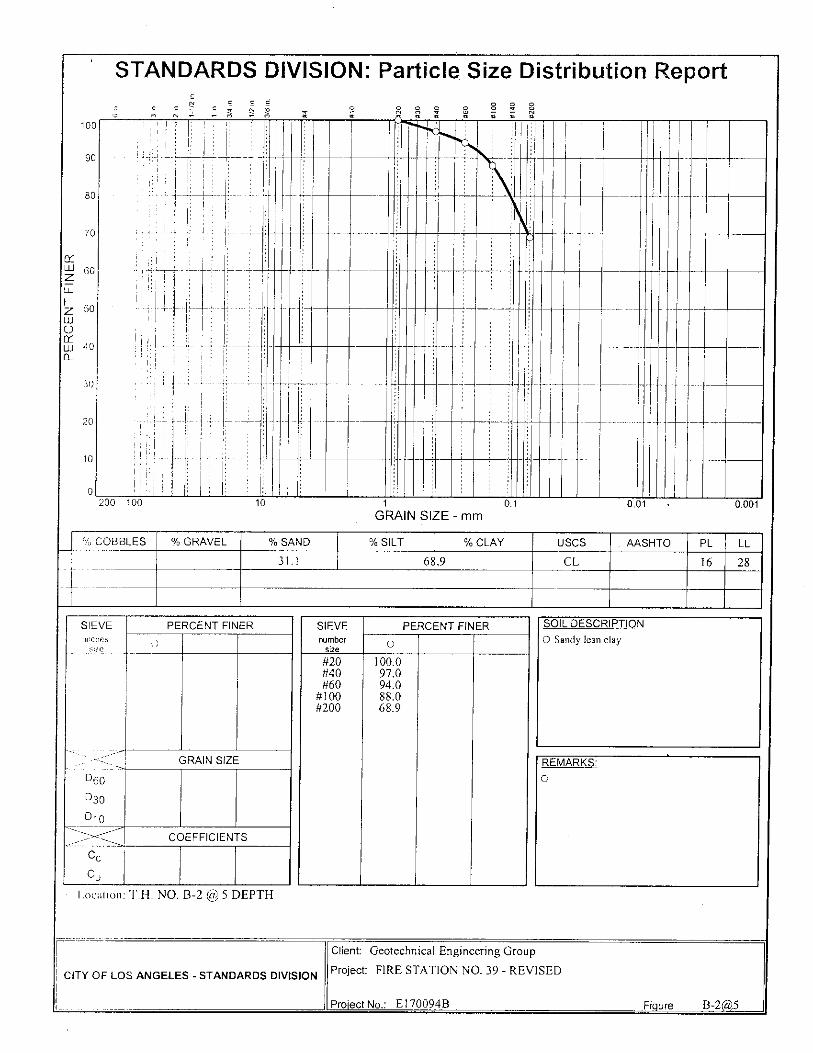
100
90
80
70
60
50
40
PE
RC
EN
T F
INE
R
30
20
10
O ,
STANDARDS DIVISION: Particle Size Distribution Report
200 100
10
01
0.01
0.001 GRAIN SIZE - mm
% COBBLES % GRAVEL % SAND % SILT % CLAY USCS . AASHTO PL LL
31.1 68.9 CL 16 28
SIEVE Inches
size
PERCENT FINER
0
__-------- GRAIN SIZE
D60
030
D10 ---________
-_____—.
COEFFICIENTS
C c
Cu
Location T.H. NO. B-2 @ 5 DEPTH
SIEVE number
size
PERCENT FINER
#20 100.0 #40 97.0 #60 94.0
#100 88.0 #200 68.9
SOIL DESCRIPTION 0 Sandy lean clay
REMARKS:
0
Client: Geotechnical Engineering Group
Project: FIRE STATION NO. 39 - REVISED
Project No.: E170094B
Figure B-2P5
CITY OF LOS ANGELES - STANDARDS DIVISION

N 00 CO NI
% SAND
13.3
80
(1/0 COBBLES % GRAVEL
100
90
70
30
20
10
200 100 10
60
50
PE
RC
EN
T F
INE
R
40
1 01 GRAIN SIZE - mm
(Y0 % SILT
CLAY
86.7
0.01 0.001
USCS AASHTO PL LL
CL 16 38
8 .7- ,c3; C7 C CO O
Trt
SIEVE inches
size
PERCENT FINER
C'
---=---____ ___---- _,-------"<---__ GRAIN SIZE
D60
D30
D10
COEFFICIENTS
o
0
Location T.H. NO. B-3 @ 10 DEPTH
SIEVE number
size
PERCENT FINER
#10 100.0 #20 99.0 #40 98.0 #60 97.0
#100 95.0 #200 86.7
SOIL DESCRIPTION
0 Lean clay
REMARKS:
0
STANDARDS DIVISION: Particle Size Distribution Report
Client: Geotechnical Engineering Group
CITY OF LOS ANGELES - STANDARDS DIVISION Project: FIRE STATION NO. 39 - REVISED
Project No.: E170094B
Figure B-3R10

STANDARDS DIVISION• Particle Size Distribution Report s s ._. ,. g , . _ _ 100
90
70 fY LIJ 60 Z Z 50 LL, . fY iii 40
30
20 10
1,
, 11111 11111 111111
II
1111111kik ::
' ■ '
1
011 11
, ,1111
11111 1111 11111
_ 1111 -- 111 , , , MI
1. , , II ;111111 111
11 I 11111 1 r , , r 1 1
11111
,
200 100 10 1 GRAIN
0 1 0.01 0.001 SIZE - mm
% COBBLES % GRAVEL % SAND % SILT % CLAY USCS AASHTO PL LL
50.3 49.7 SM 19 22
1 .
SIEVE inches size
PERCENT FINER SIEVE number
PERCENT FINER SOIL DESCRIPTION
size
0 Silty sand
#4 #10 #20 #40 #60
#100 #200
100.0 99.0 95.0 88.0 78.0 67.0 49.7
__. GRAIN SIZE REMARKS:
060
D39
D10
0. 1 1 2 0
------- COEFFICIENTS
C c
Cu
Location T.H. NO. B -3 @ 15 DEPTH
CITY OF LOS ANGELES - STANDARDS DIVISION
Client: Geotechnical Engineering Group
Project: FIRE STATION NO. 39 - REVISED
Project No.: E170094B Figure B -3P15

STANDARDS DIVISION: Particle Size Distribution Report c ,, _ _ 7 ',_, ,-..., c>,
— — , r
0 7t 3t 7t 7k Yt 3t Yi ik 3t
100
90
80
70 C 1-1-1 60 Z Er_ 1-- z 50 CD
40 CL
30
20
0
11111
11111
I a ----. -- -
.
W 111111 --
1 0
200 100 10 1 GRAIN
0 1 0.01 0.001 SIZE-mm
Li 2 COBBLES % GRAVEL `)/0 SAND % SILT % CLAY USCS AASHTO PL LL . L 2.0 51.0 47.0 SM NP NP
SIEVE I mcheS size
PERCENT FINER SIEVE number
size
PERCENT FINER SOIL DESCRIPTION
C 0 0 Silty sand
3:8" 100.0 #4 #10 #20 #40 #60
#100 #200
98.0 95.0 90.0 81.0 72.0 62.0 47.0
.::---_: --._ GRAIN SIZE- REMARKS:
D50
D30
D10
0.136 0
<-■ COEFFICIENTS
C c
Cu
Location T.I-I. NO. B-3 @ 25 DEPTH
,-,-- Client: Geotechnical Engineering Group
Project: FIRE STATION NO. 39 - REVISED
Project No.: El 70094B
CITY OF LOS ANGELES - STANDARDS DIVISION
Figure B-3 a,25

, STANDARDS DIVISION: Particle Size Distribution Report
cJ , c., , _ , ,_ , z ,,,, s ,,,3t ik
s s ,,2 , , ,J . . 100 90 80 70
CC w60 Z I-- z 50 0 w
tY W 40 Cl_ 30 20
' •
111111111b..
1111
III i 1 I IIII
1
H I t_ _
1 i 1 ,
,
"
I
I
I
rill
101111 I 0 - --. !---
1 - ,
1 1.11 1111 III 11111
1 ' . -4 11 11 I Ill I b la 1 200 100 10 1
GRAIN 0 1 0.01 0.001
SIZE - mm
% COBBLES % GRAVEL )̀/0 SAND % SILT % CLAY USCS AASHTO PL LL
1.0 46.6 52.4 CL-ML 18 22
SIEVE inches
size
PERCENT FINER SIEVE number
size ,_ J
PERCENT FINER SOIL DESCRIPTION
Sandy silty clay o
3;5" 100.0 #4 #10 #20 #40 #60
#100 #200
99.0 97.0 91.0 84.0 76.0 66.0 52.4
-------- GRAIN SIZE REMARKS:
D60 D30 D10
0.111 0
.
-------- - ->--------- -__ COEFFICIENTS
C c
Cu
, -, Location T.H. NO. B -3 @ 35 DEPTH
CITY OF LOS ANGELES - STANDARDS DIVISION
Client: Geotechnical Engineering Group
Project: FIRE STATION NO. 39 - REVISED
Project No.: E170094B Figure B-3 u,35

STANDARDS DIVISION . Particle Size Distribution Report . , . .,- . . . -,- 8 , .
(:) , N,, •- A N'A 1 - 411 g '4? ;; 41' • 100
90
80
70
CY I-I-J 60 Z
I— z 50 111 0 CC W 40
30
20
0
-4- H
, ,
.
--
r
LT:
1;
10
r
1-
--1-;
.
i
1
--,- --, -,-
•
200 100 10 1 GRAIN
0 1 0.01 0.001 SIZE - mm
% COBBLES % GRAVEL % SAND % SILT % CLAY USCS AASHTO PL LL
16.8 83.2 CL 15 38
SIEVE inches
size
PERCENT FINER SIEVE number
size
PERCENT FINER SOIL DESCRIPTION
0 Lean clay with sand
#10 #20 #40 #60
#100 #200
100.0 99.0 98.0 97.0 94.0 83.2
>< GRAIN SIZE REMARKS:
D60
D30
D10
0
COEFFICIENTS
C c
Cu
l .ocation T.H. NO. B -4 @ 10 DEPTH
CITY OF LOS ANGELES - STANDARDS DIVISION
Client: Geotechnical Engineering Group _
Project: FIRE STATION NO. 39 - REVISED
Project No.: El 70094B Figure B-4(10
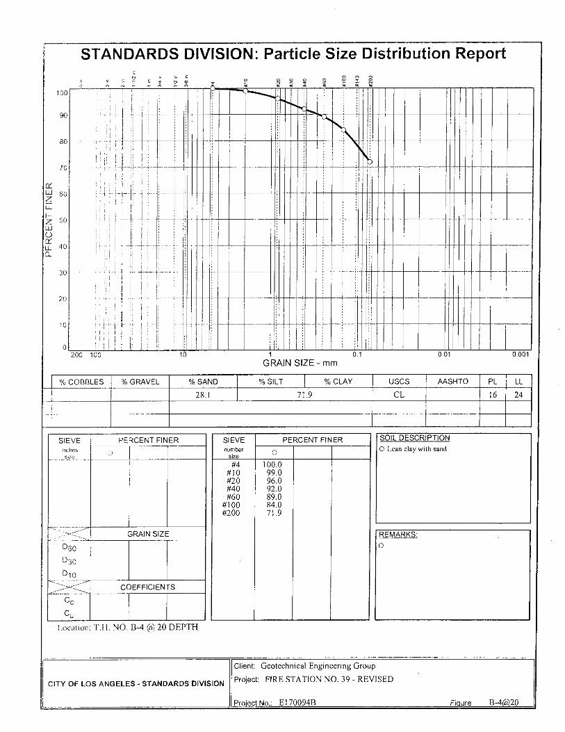
STANDARDS DIVISION: Particle Size Distribution Report O
O O O
O 8
8 O
cO
it
-, _ •
' r 1 .
1 2on 1no lo 1 0 1 0.01 0.001
GRAIN SIZE - mm
COBBLES % GRAVEL % SAND % SILT % CLAY USCS AASHTO PL LL
28.1 71.9 CL 16 24
PE
RC
EN
T F
INE
R
100
90
80
70
60
50
40
30
20
10
0
SIEVE inches
size
PERCENT FINER
!)
-----_ ____----- GRAIN SIZE
060
D30
0 10 ------- COEFFICIENTS
Cc
Cu
SIEVE number
size
PERCENT FINER
0
#4 100.0 #10 99.0 #20 96.0 #40 92.0 #60 89.0
#100 84.0 #200 71.9
SOIL DESCRIPTION
0 Lean clay with sand
REMARKS:
0
Location: T.H. NO. B-4 @ 20 DEPTH
Client: Geotechnical Engineering Group
Project: FIRE STATION NO. 39 - REVISED
Project No.: E170094B
CITY OF LOS ANGELES - STANDARDS DIVISION
Figure B-4 P20

STANDARDS DIVISION: Particle Size Distribution Report
E ,c1J- ; , Jo .., ,., E P4 F, ii i) il ! Fic ,
100
90
80
70
CL 1-1-I Z 60
LE
z 50
0
Li j 40
30
10
,
LU
_
1
fi
200 100 10 1 GRAIN
0 1 0.01 0.001 SIZE - mm
% COBBLES `)/0 GRAVEL % SAND % SILT )̀/0 CLAY USCS AASHTO PL LL
28.2 43.8 28.0 CL 13 29
SIEVE
inches size
PERCENT FINER SIEVE number
size
PERCENT FINER SOIL DESCRIPTION
0 Lean clay with sand 0
#20 #40 #60
#100 #200
100.0 99.0 97.0 92.0 71.8
GRAIN SIZE REMARKS:
D60
D30
D10
0.0492
0.0063
0
COEFFICIENTS
C c
Cu
location T.H. NO. B-5 @ 5 DEPTH
---
CITY OF LOS ANGELES - STANDARDS DIVISION
Client: Geotechnical Engineering Group
Project: 5896
Project No.: E170094B Figure B -5 a,5

STANDARDS DIVISION: Particle Size Distribution Report
0,,2_ , ! „, ! . . . 0 8 c4 8 r. , c, ,, —, — 4 T, ,' Q 4 V, 71 ;, 7t4
100
80
70
Z LT:
I-- Z 50 UJ 0 Q Lij 40 CIL
30
20
0
,
I-1-1 60
4 ,
, _,
, , ' ' —
,
1
, t - T-
1 0
200 100 10 1
GRAIN 0 1 0.01 0.001
SIZE - mm
% COBBLES % GRAVEL % SAND % SILT % CLAY USCS AASHTO PL LL
1.0 65.8 33.2 SM 15 18
SIEVE
inches size
PERCENT FINER SIEVE number
size
PERCENT FINER SOIL DESCRIPTION
0 Silty sand 0
3/5"
--------
100.0 #4 #10 #20 #40 #60
#100 #200
99.0 96.0 90.0 79.0 64.0 48.0 33.2
GRAIN SIZE REMARKS:
D60
D30
D10
0.221 0
''.>< COEFFICIENTS
C c
Cu
Location T.H. NO. B-6 @ 15 DEPTH
CITY OF LOS ANGELES - STANDARDS DIVISION
L
Client: Geotechnical Engineering Group
Project: FIRE STATION NO. 39 - REVISED
Project No.: E170094B Figure B-6 a,15

STANDARDS DIVISION: Particle Size Distribution Report
(7, F) O O O O O it
O O
O
;1- O O
.....
1
I
■
1
r
■
f , r -r
v
■
t rf , -I i
200 100 10 1 0 1 0.01 0.001 GRAIN SIZE - mm
PE
RC
EN
T F
INE
R
100
90
80
70
60
50
40
30
20
10
0
'/(-, COBBLES % GRAVEL % SAND % SILT % CLAY USCS AASHTO PL LL
33.0 67.0 CL 14 26
SIEVE inches
size
PERCENT FINER
()
—,--- ----- GRAIN SIZE
D60
D50
D10
COEFFICIENTS
U D
0 0
SIEVE number
size
PERCENT FINER
0 • #1 0 100.0 #20 99.0 #40 97.0 #60 92.0
#100 86.0 #200 67,0
SOIL DESCRIPTION 0 Sandyl,:an clay
REMARKS:
0
Location: T.H. NO. B-7 @ 5 DEPTH
Client: Geotechnical Engineering Group
Project: FIRE STATION NO. 39 - REVISED
Project No.: E170094B
Figure B-7A5
CITY OF LOS ANGELES - STANDARDS DIVISION

80
70
10
--I 60
z 50
C.)
40 0
30
20
10
200 100
100
90
0.1
0.01
0.001
O 8 8 i" '; ̀11 N c7
STANDARDS DIVISION: Particle Size Distribution Report
GRAIN SIZE - mm
% COBBLES % GRAVEL % SAND % SILT % CLAY USCS AASHTO PL LL
1.0 10.3 88.7 CL 18 39
SIEVE inch,
size
PERCENT FINER ,--,
I2" 3/8"
1 00.0 99.0
--------, ____---- --,
__-- ------___ GRAIN SIZE
D60
D30
D10
COEFFICIENTS
U 1
1,ocmion T.H. NO. B-8 @ 10 DEPTH
SIEVE number
size
PERCENT FINER
#4 99.0 #10 99.0 #20 98.0 #40 98.0 #60 97.0
#100 95.0 #200 88.7
REMARKS:
0
SOIL DESCRIPTION
0 Lean clay
CITY OF LOS ANGELES - STANDARDS DIVISION
Client: Geotechnical Engineering Group
Project: FIRE STATION NO. 39 - REVISED
Project No.: E170094B
Figure B-8(a,10

z
0 ro
4.)
E170094
B
Wor
k O
rder
No
: R
EV
ISE
D
ST
AT
IO
N
00
O
ITY
OF
LO
S A
Nc
DE
PAR
TM
EN
T O
F G
EN
ER
AL
SE
RV
ICES
\
QD
O ,t1 H
• :
O z ,-0
7c1

z
c/D
H
Shee
t 2 o
f 8
qD,
co
H 7t■
d z
E1
70
09
4B
W
ork
Or d
er N
o:
RE
VIS
ED
0)
ST
AT
ION
H ,-0 O
L S
ER
VIC
ES
LO
S A
NG
ELE
S

Shee
t 3 o
f 8
E170094B
L S
ER
VIC
ES
D
EP
AR
TM
EN
T O
F G
EN
E
Wor
k O
r der
No:
REVISED
CIT
Y O
F 1
_()
S \
NC
,
FIRE STATIpN #39
O Z '
0 S
.Z
0 T
0 S
S O
f, S
E 0 E
S
_
_
6'st 1E
.9 L'
6 9-1T
0.0T
8'ZT
0'6
UTT ; T7'
91
L'OT
O'ZT
9'6
. _
97
7
8 7
2 7
6
'Sam
ple
Dep
t h,
ft.
1
1 1 IIn
Plac
e D
ry D
ens i
ty, p
cf
1 IP
ield
Moi
s tur
e, %
I
-
1 IL
a b M
ax D
ry D
ensi
ty, p
cf
. _
r
a b O
pti
mum
Mo
istu
re, %
,
1
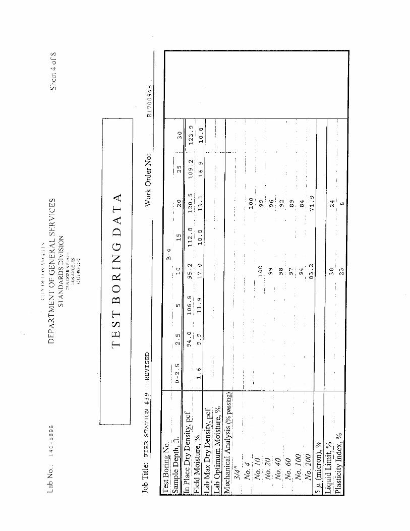
She
et4o
f 8
REVISED
E170094B
Wor
k O
r der
No:
STATION
H
O z c
a) •
H ,•0 0 ti
lfl O1 00 U )
O di
cr)
U
(/
ce
z rw
O H z 2 H
cL
C
O
(1 I 1
OP
I .(); ( 1
-
2319 D
OR
RIS
PLA
CE
L
OS
AN
GE
LE
S
(21
3) 4
85- '
242
CT)
cl)
H
z
0 CI) H C/D
H
OE
1 SZ
OZ
ST
OT
S S'
Z S'
Z-0
f-E
8'0T
6'9T
T'ET
8'0T
O'LT
6—ET
6'6
9'T
6'EZT
Z'60T
S'OZT
8'ZTT
Z'S6
8'90T
0'f6
6'TL
Z*E8
te f6
68
L6
Z6
86
96
66
66
00T
00T
5 µ
(mic
ron)
, %
Liq
u id
Lim
it, %
38 24
Pla
s tic
ity
Inde
x, %
23 8
Tes
t Bor
ing
No.
, Sa
mp
le D
ept h
, ft.
. In
Pla
ce D
ry D
ens i
ty, p
c f
Fie
ld M
ois
ture
, %
La b
Max
Dry
Den
s ity
, pcf
Lab
Op
t im
um M
ois
ture
, %
Mec
han i
cal A
n aly
sis
(% p
ass i
ng)
No.
4
No.
10
N
o. 2
0
No.
40
No.
60
No.
10
0
No.
200
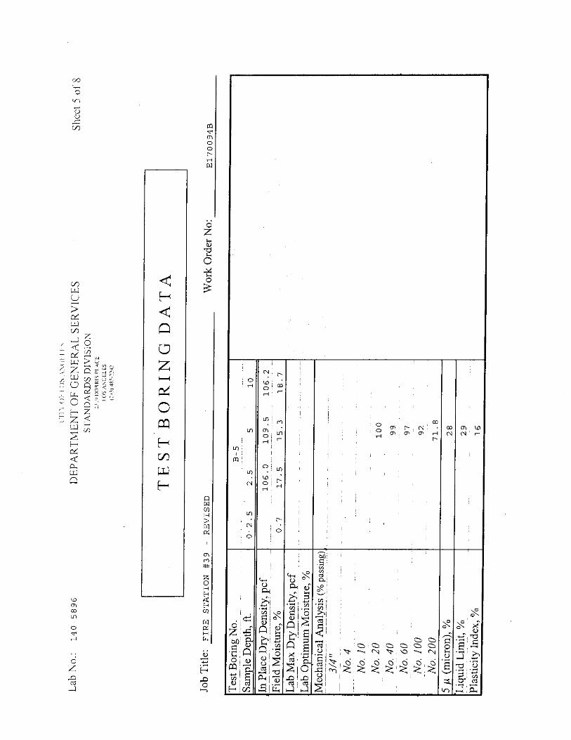
0 H
L
N
0
CO 0 H
cr)
LID 0 H
CD i
O r-I H
N
0
0;0 i0 0 CZ: ! c:2) !
! N
a)
(/)
She
et 5
of 8
RE
VIS
ED
Ol cY)
ST
AT
ION
H ,C) 0 ti
E1
70
09
4B
W
ork
Or d
er N
o:
1-1-)
re LL C/)
7
CD H z
H C4
S D
IVIS
ION
Crn
up- \O
H I
. ,
2319 D
OR
RIS
PLA
CE
:11
,
rt
r
CO N
O

H di H H
H
LO 0 H
0
N
0) N
a) H
O N
H
O H
U)
Ln
O
O O H
Ol W 0 dl al ;
N di 00 ' •
•71, rn
sY1
H
H
H
N
C Ln
di
H
H
0 H
00
N H
O
a)
Shee
t 6 o
f 8
(213
) 48
5-22
42
H
Ca
z
0 0 0 CZ) 0 0 N
"q- 6 6 6 6 6 6 6 M
00 H
RE
VIS
ED
S
TA
TIO
N
H
• •
••••••4 -4••••.
H r.0
ti
0
E
0
E1
70
09
4B
W
ork
Or d
er N
o:

0
Wor
k O
r der
No:
R
EV
ISE
D
ST
AT
ION
(24 H
•
H 0 ti
Shee
t 7 o
f 8
E170094B
CIT
Y O
F 1.
0S
AN
(
DE
PAR
TM
EN
T O
F G
EN
E
L S
ER
VIC
ES
0
N
O N
H
H
0 H
•
0 H
N
01, H 01 I N
al O
0 H
ct, 0
H
O 01 N , NI CD 01I 01 01 I CO
N -
PI
CD N N H
N
O
rn co to
0
H
0 z
0 0
O c.)
tr)
?4
61 6 1 6 6 0'0 o

• N Wo • H N
N
z
0
4-)
O z _.0
Shee
t 8 o
f 8
E1
70
09
4B
W
ork
Or d
er N
o:
RE
VIS
ED
F
IRE
ST
AT
ION
#39
C)
H 0 ti
O
H
N N H
CO Lfl
Lfl N
0 O
N
0 W
rel H
Ln
N
O
O
LO
CO
H
0
.41
Cf)
00 OD i • 011 OH M 011 00
1 ! CO
O N
N Ol H
Ol H N
0 z bO
cr.
64 a)

PERCOLATION TEST DATA Project Title: FIRE STATION NO. 39 - REVISED Work Order No.: E170094B
Location ID: B-5/TW-1
Date: 3/10/2012
Total Borehole Depth: 10'
Test Personnel: J. Kunesh
Comments: Percolation Zone from 5 1-10' depth
(Official Test)
GPS Coordinates: North 34° 10' 46.69"
West 118 ° 27' 05.90"
Clock Time
(hh:mm)
Total Test Time
(min)
Increment of Time
(min)
Total Cumulative Water added
(gallons)
Incremental Water Added
(gallons)
Average Incremental Flow
Rate (gal/min)
9:25 0 0 0 0 0.000
9:30 5 5 4.70 4.70 0.940
9:35 10 5 8.40 3.70 0.740
9:40 15 5 11.94 3.54 0.708
9:45 20 5 15.43 3.49 0.698
9:50 25 5 18.86 3.43 0.686
9:55 30 5 22.24 3.38 0.676
10:00 35 5 25.50 3.26 0.652
10:05 40 5 28.72 3.22 0.644
10:10 45 5 31.98 3.26 0.652
10:15 50 5 35.16 3.18 0.636
10:20 55 5 38.28 3.12 0.624
10:25 60 5 41.30 3.02 0.604
10:30 65 5 44.30 3.00 0.600
10:35 70 5 4730 .., 3.00 0.600
10:40 75 5 50.36 3.06 0.612
10:45 80 5 53.38 3.02 0.604
10:50 85 5 56.42 3.04 0.608
10:55 90 5 59.44 3.02 0.604
11:00 95 5 62.40 2.96 0.592
11:05 100 5 65.37 2.97 0.594
11:10 105 5 68.32 2.95 0.590
Page 1 of 3

PERCOLATION TEST DATA Project Title: FIRE STATION NO. 39 - REVISED Work Order No.: E170094B
Location ID: TW- 1
Date: 3/10/2012 Total Borehole Depth: 10'
Test Personnel: J. Kunesh
Comments:
Percolation Zone from 5'-10' depth (Official Test)
GPS Coordinates:
North 34° 10' 46.69"
West 118° 27' 05.90"
Clock Time
(1 -ih:mm)
Total Test Time
(min)
Increment of Time
(min)
Total Cumulative Water added
(gallons)
Incremental Water Added
(gallons)
Average Incremental Flow
Rate (gal/min)
11:15 110 5 71.18 2.86 0.572
11:20 115 5 74.16 2.98 0.596
11:25 120 5 77.06 2.90 0.580
11:35 130 10 82.70 5.64 0.564
11:45 140 10 88.32 5.62 0.562
11:55 150 10 94.24 5.92 0.592
12:05 160 10 100.06 5.82 0.582
12:15 170 10 105.96 5.90 0.590
12:25 180 10 111.60 5.64 0.564
12:35 190. 10 117.36 5.76 0.576
12:45 200 10 123.20 5.84 _._
0.584
12:55 210 10 129.00 5.80 0.580
13:05 220 10 134.67 5.67 0.567
13:15 230 10 140.28 5.61 0.561
13:25 240 10 145.88 5.60 0.560
13:35 250 10 151.38 5.50 0.550
13:45 260 10 157.14 5.76 0.576
13:55 270 10 162.82 5.68 0.568
14:05 280 10 168.37 5.55 0.555
14:15 290 10 174.07 5.70 0.570
14:25 300 10 179.72 5.65 0.565
14:40 315 15 188.20 8.48 0.565
Page 2 of 3

PERCOLATION TEST DATA
Project Title: FIRE STATION NO. 39 - REVISED Work Order No.: E170094B
Location ID: B-5/TW-1 Total Borehole Depth: 10'
Comments: Percolation Zone from 5'-10' depth
(Official Test)
GPS Coordinates: North 34° 10' 46.69" West 118° 27' 05.90"
Clock Time
(hh:mm)
Total Test Time
(min)
Increment of Time
(min)
Total Cumulative Water added
(gallons)
Incremental Water Added
(gallons)
Average Incremental Flow
Rate (gal/min)
14:55 330 15 196.63 8.43 0.562
15:10 345 15 205.06 8.43 0.562 15:25 360 15 213.36 8.30 0.553 15:40 375 15 221.84 8.48 0.565 15:55 390 15 230.20 8.36 0.557 16:10 405 15 238.60 8.40 0.560 16:25 420 15 246.98 8.38 0.559 16:40 435 15 255.44 8.46 0.564 16:55 450 15 263.96 8.52 0.568 17:10 465 15 272.46 8.50 0.567 17:25 480 15 280.98 8.52 0.568
END OF TEST
Notes: a. Parking lot locked until 9:00 am b. 13 Gallons of water added prior to test period (establish head) c. Diameter of percolation zone = 9 inches d. Water head from surface to 5' below surface.
Page 3 of 3

CI T
Y O
F L
OS
AN
GE
LE
S
2319
DO
RR
IS P
LA
CE
ST
AN
DA
RD
S D
IVIS
ION
DE
PA
RT
ME
NT
OF
GE
NE
RA
L S
ER
VIC
ES
TE
ST
DA
TA
Job
Nu
mb
er:
Co
mp
os
ite
Da
ta
_ =
=
C\1 • h.-
0 •
E-1.61,
.,•-•-
9 06
9
00
-0
T.—
LCi
I /9
'0
oo.o
0'9 L.
0)
4 C\1
00'0
■ ,
9.611.
t72.0
00'0
Z'L
0'9 I.
9.09
Z
00'0
Z.91.
28'0 ocyo
Init i
al M
ois
ture
%
Mo
istu
re a
fte
r so
aki
ng%
Dry
De
ns
ity, p
. c. f
.
Exu
datio
n P
ress
ure
, p. s
.i.
!Exp
an
sio
n P
ress
ure
De
velo
pe
d, p
. s.i
.
Sta
bilo
me
ter
"R"
Va
lue
Th
ickn
ess
ind
ica
ted
by
Sta
bilo
me
ter,
ft.
• • .
Thi
ckne
ss in
dic
ate
d by
Exp
ans
ion
Pre
ssur
e, f
t.
O
C)
0
I CO co
O
O ti
Tra
ffic
Inde
x*
Gra
vel F
acto
r
5 a
O cT)
O
C O
C O
5 U) U)
C
0
E
FIR
E S
TA
TIO
N #
39 -
Rev
ised
co 0) O O
C O
8 Co
C\1 ti
C O
C)
SO
IL S
AM
PL
E
O O
0) U)
0_
-0 C
47, U) C)
a-
CO
MP
OS
ITE
SO
IL D
AT
A
:=1
0-
CL
/ Le
an c
lay
wit h
sa
nd
CO
11111111■I
—J

LC)
C<1 O O CN
O C.) O O
O Ln LC)
C
co
CN CY)
L()
O O
CY)
O
*giv
en
by
tes
t req
ues t
or
0)
O
O 0 O
C\1 00
C\J 0-) O co 1--
Co
(N.1 O O O
Ln O
0 0 0
0 0
O CO LO 0)
CO
LO
0 O
0
as
a
Exp
ans
ion
Dia
l
Tra
ffic
Inde
x, T
I *
Gra
vel F
acto
r, G
f
Thi
ckn
ess
from
plo
t,To
ot:
O O
O
411.111■11.1•■
0.00
32
(TI)
( 100
- Rsta
b )/G
f T
hic
k by
sta
b =
LC)
CO
a) C (/) _ O E
O
O
co O co
N- C) Lr)
O O C\I
If)
(..C3 CO
CO
0
0 0)
0 co 0
0 CNI O
O
0 o
6 ° ° ° ̀O .Y
o o a , COD , m cv ,-, o O a a a d a a 6
(4) Jalawilmels Aq ssatmomi i 0 /too
4- cfl c. cc a) co c) co 0
8 -1- tj
(/) U) a) C
:E
CDU CN II
0
Li- 43 U C° _e 2
w a)
CD CD

Fo! m GS/STD 911
CITY OF LOS ANGELES
DEPARTMENT OF GENERAL SERVICES
STANDARDS DIVISION 2319 DORRIS PLACE
LOS ANGELES, CA 90031 (213) 485-2242
FAX (213) 485-5075
Lab.#: 12-00396 (140-5896) Fire Station # 39 - Revised W.O.#: E170094B
Received: May 01, 2012 Reported: May 18, 2012
To: File Copy.
Cc: Javad Valleie
SAMPLE ANALYSIS RESULTS
At the request of the Geotechnical Engineering Group of the Bureau of Engineering, one sample collected from the Fire Station # 39 - Revised project was analyzed for acidity, chlorides, sulfates, conductivity, and pH.
The sample was analyzed in accordance with the California Department of Public Health's Environmental Laboratory Accreditation Program (ELAP) approved methods. The specific methods are listed on the data sheets.
The chain of custody and data sheets are attached.
KABEW KASSEW, Laboratory Manager II General Services/Standards
KK: C DW:MC:mc

■ D
ate
R
epo
rte
d
05/1
8/20
12
05/1
8/2
012 1
05/1
8/2
01
2
05/1
8/2
012
05/1
8/2
01
2
Da
te
An
aly
zed
05/0
8/2
01
2 Z
I,OZ/8
0/9
0 05
/08
/20
12
05/0
8/2
012
05/0
8/2
01
2
pold
we
s are
a
03
/01
/20
12
ZI-O
Z/LO/C
0
Z O
Z/ LO/a
) 03
/01
/20
12 Z
OZ/ I- 0/C
O
Me
tho
d
SM
2310B
VO
ZI• V
dD E
PA
300
. 0
SM
450
0-1-1
+B
EP
A 3
00. 0
,
An
aly
st
Sd
,
Sd
Sd
Sd
•
Sd
-121
..
01-
V/N
Z•0
V/N
0'
SI! 1.1 n
mg
Ca C
O3/L
(P
P m)
iirn
hos /
cm
116w
V/N
ii5 w
;
nns
ay
ON
Z-k6
617'0
6.1"Z
'
•
Ana
lyte
Aci
d ity
Co
n duc
t ivity
Chl
orid
es
Hd
Su
lfate
s
, ,
...._
Sam
ple
Des
crip
tion
B -
6 @
0 -
2. 5
' LTZ - 0
9-9
.g Z - 0 g
9 - 9
.G.Z - 0 g
9 - 9
- 0 g 9
- 9
(
:-1
1
1
c
,...
(
'...
La
bora
tory
1.
D.
v 1.0-96
e00,Z
l- 12- 0
0396
- 01
A v
1-0-96e0
0-ZI, 12
- 003
96- 0
1 A
12- 0
0396
- 01
A
t c a
C
c
CIT
Y O
F L
OS
AN
GE
LE
S
13) Co
_C 0 Co a)
Samp
le
Typ
e:
Fire Station #
39 -
Rev
ised
a)
2 a.
• -ci a) N
C CO (1) CO
a)
a)
0) C
U)
EL..)
C
U)
E c.-.
as Co
cO
C
I)
co 0
a)
(.)
O ca. <
5 5 5z a
z
< z z

CITY OF LOS ANGELES Department of General Services Standards Testing Laboratory
Location: Fire Station # 39 - Revised
Date Received: 05/01/2012
Analyte Chloride Sulfate
QC
True Value 3.00 10.0
QC1 2.92 9.89
Rec 97.4 98.9
QC2 2.97 9.95
% Rec 98.9 99.5
Rec Control Limits
90.8 86.5
- -
113 112
RPD 1.49 0.56
RPD Limit 4.97 5.60
Sample
Sample 0.433 5.12
Sample Dup 0.542 5.12
RPD 22.4 0.04
RPD Limit 10.6 5.76
Spike
Spike Amt 6.67 13.3
MS 10.8 18.7
% MS Rec 112 102
MSD 10.5 18.9
% MSD Rec 108 103
59.1 76.4
Rec Control Limits - -
150 124
RPD 2.73 1.18
RPD Limit 9.46 7.01
N/A - Not Applicable ND - Not Detected Note: The Sample RPD exceeded the control limits.

LABORATORY ABBREVIATION.S
ASTM American Society for Testing and Materials
BNA Base-Neutral/Acid Extractables
BOD Biochemical Oxygen Demand
COG Chain of Custody
DRO Diesel Range Organics
ECD Electron Capture Detector
ECF East Curb Face
ELAP Environmental Laboratory Accreditation Program
EPA Environmental Protection Agency
FID Flame Ionization Detector
Grams
GC Gas Chromatograph
GC/MS Gas Chromatograph/Mass Spectrometer
GRO Gasoline Range Organics
GSD General Services Division
HEM Hexane Extractable Material
ICP Inductively Coupled Plasma
KG Kilograms
L Liter
LCS Laboratory Control Sample
MBAS Methylene Blue Active Substances
MDL Method Detection Limit
MG Milligrams
ML Milliliter
MS Matrix Spike
MSD Matrix Spike Duplicate
NA Not Applicable
NCF North Curb Face
ND Not Detected
PAT Purge and Trap
PCB Polychlorinated Biphenyls
PPB Parts Per Billion
PPM Parts Per Million
PRG Preliminary Remediation Goals
QA Quality Assurance
QC Quality Control
RL Reporting Limit
RPD Relative Percent Difference
SCF South Curb Face
SM Standard Methods
STLC Soluble Threshold Limit Concentration
TCLP Toxicity Characteristic Leaching Procedure
TPH Total Petroleum Hydrocarbons
TRPH Total Recoverable Petroleum Hydrocarbons
TTLC Total Threshold Limit Concentration
VOC Volatile Organic Compounds
WCF West Curb Face
WET Waste Extraction Test

cu E 0
Cu
rre
nt
Ho
ld
-4-
(ll
0 CD
C) C O
0)
01 C)
O
O
a)
C
S-(
O
c(
- CO Cs4 CN (N c,)
_0— -0— _C) 0 0
—J u
. 0 C 0 E
a) a) cn cp _c 0 u
0) 0 0
C 0
41, 0 CO C 0 0)
O
La
bora
tory
Use O
nly
Labo
rato
ry L
og N
umbe
rs
Drk
Or d
er N
o.
Dm
ple
Lo
catio
n/ A
ddre
ss:
0 0 t-o
Uc`l
< CN O U Lit)
co
O (,) O C cat
< (-) • • x fl
E
a) 0
E 0
C 0
•
a.) C
0 C 0)
6_ O
0

Sam
ple
Ma
trix
: S
H C24
ccd
O6
12- 0
0396
- 01
Frid
ay, M
ay 1
8, 2
012
Soil
Lea
c h T
est (
S O4,
C1, C
ond.
,pH
,Ac
idity
)
H
f24
•—
cd
0 4-4 -a C) 0
-0 0 0 CO C)
as +a'
Cl) c'd 77i
0:1 • •
PL.+ Cr;
0 • p
• 0 r
0.)
i--. cr, .5 , (/)
%." '4 >, 1 _o • 7t-cf)
:`,:' a.< (S.' ? c) cp z — r--•
.; • • --, LL)
'I' c)
-g-3, --, 2 ----- 0
cp .--
) Cl) O
U 71-
h- U
•
< (-L-- • ___, ) 0 4t ,L) • (.) 0-
CU (1.) • C4
4a' Cie)
5 --„ . cn .._.,
""64 cl)
▪ C4 =..o CT
= cn
Cr '44
.74 44 0
;.-( • —
C Clo a) CU ,.. . --.
r:4 ..-■
vp ,_ ON
I) 0 00 C1) c
C f 8 ..,r C.) 0


Fire Station #39 February 15, 2013
APPENDIX B
Standards Report of Subsurface Investigation (Supplemental) Dated July 16, 2012


FIRE STATION NO. 39 - REVISED (Supplemental)
LAB NO. 140-5896
W.0 NO. E170094B JULY 2012
GEOTECHNICAL SERVICES FILE: 12-002


I.M3. No.
REQI ESTEI)
It F PORTED
To
140-5896
07-05-12 07-16-12 Gary Lee Moore City Engineer Att'n: Christopher J
CITY OF LOS ANGELES
DEPARTMENT OF GENERAL SERVICES STANDARDS
2319 DORRIS PLACE LOS ANGELES, CA 90031
(213) 485-2242 fax (213)485-5075
ohnson
Fire Station No. 39 (Supplemental)
W.O. No. E1700094B File No. 12-002
Report of SUBSURFACE INVESTIGATION
(Supplemental)
Transmitted are the additional test results of the subsurface investigation performed by Standards on the above-named project as requested by the Geotechnical Engineering Group (GEO) of the Bureau of Engineering. The soil classification is based on the attached Unified Soils Classification System.
I
RAY H. SOLOMO "General Services/Standar\-
PKH:JV:KSN:MNR:m


---
sn.opt =Ma onNaaanYv 4001••■■••••■■••••••.•••-mbrrobabroarbwmrie
Soils ! hod 0:ou es an.lIL.iyourol by BOUNDARY CI ASSII [CATIONS
3/4 in
SIZE
No 00 fro 410 No . 10 hie 4
U. S Cl Ai4DAfin
UNIFIED SOIL CLASSIFICATION SYSTEM *
MAJOR DIVISIONS GROUP
SYMBOLS TYPICAL NAMES
COARSE
SOILS
ninterittl is LARGER than
,.200 binvo chat
GRAINED ?\/)1110121,1i1111
GR AVELS
More than 50 %
of coerce fraction
is LARGER than
the Not4
sieve sleep
CLEAN t,:„ztti
GRAVELS
U • • v.
i41)'9
Gw Well grerferl uravals. wavol-stind nsixtures little nr no
Nice.
little or no roast ..: 'Y.
• •
,
Gp Poorly cireclati (travels or grnvol-sand mishitne. little nr
no linos.
GRAVELS I. WITH FINES
anlnnnt of Cowl
2
G m Silt tfravalc, wavol-f- end-silt rill s a e.
)1/ GC Clayey untyyla, orttval nand-clay rnisteran.
(Moro than 50% of
SANDS {Little
(More than 50%
of coarse fraction
- -Sfy1/11 I. ER than
the No. , '
cinoosi,o
CLEAN
SANDS
y—Sac i ;:.::;:-;,,-
- -olf• sw ' '1 '
Well ten , ltel OfirOT:. orovolly stasis. Lula or no Stec.
lit- no liorG1 L
I -
cn Pooily grailtal sands or fp ovally selfOifi little or no
lin " ° -
SANDS .. .: — ln
WITH FINLS o ::'
s m Silty nand: colol-silt InGtorcs.
lAraccolohlo
tltni ,r of finttn)
/-7..-.,-, s/ n a Clicroy. Gacln ,.,lid-clay mixioloc
FINE IF
GRAINED
(m,irg, Hum 50% of
iuttwi1 ic
:;MAt I Hi th.,
!•10.200 clove mint
SILTS Ai\JD C:LA',/1; Hi:id lirset I I SR than hill
.
,/.
■
.
,<,
it chlytty
MI_
,..
Hip panic oiliii no,/ rimy f i n ,, ;,, „ to, i o nic iii,, , „ifty 4 ,
Eno c..tcla or oL-lyny lido; will% olloht plasticity.
- oloyc, ',ash !, ,lass, odic cloys, Ical flay --
SOILS 1
trr
SILTS AND CI CLAYS II HNC] limit GliCkftli than 501
11
,„
I• „,,,,,,„.•,1•„,,,„k.
Inn , uniAair, ••1 Roll pia:heat fat clays. GI
X/
--/ -
01.-I Ofttanic clay:. of modaun Kith RI:a:tit:4y, oft iic
Its.
HIGHLY ORGANIC SOILS A..n SiA74 -
pt IHnt and &thes highly nncalIC loiN
coothinations of gripes synd,cla
PARTICLE SIZE LIMITS
SILT OR CLAY COBc3I.E5
12 ot
RGULDCRS
SAND GRAVEL
VINE 1,14411Lif,4 coARsc I ilyE r son-se
* Referense:
The Unified Soil Classification System. Corps of Engineers,
U.S. Army Technical lAereorandui 'o. 3-357, Vol. I, Marco 'Pea.
(Revised April, 196CT
CITY OF LOS ANGELES
DEPARTMENT OF GENERAL SERVICES STANDARDS DCVIS1ON
21? Vali:3 PLACE
LOS ANGELES CA oT031
(SIP) 4IS-7242

STANDARDS DIVISION: Particle Size Distribution Report
c?- 2 8 8 8
100
90
80
70
a 1-1-1 60 Z LL
z 50 IL
a 40
a
30
20
10
0
-••••.,;....0
I
1 I 1
F—
: 1 ' 1
1
H
1
200 100 10 GRAIN
0 1 0.01 0.001 SIZE - mm
j % COBBLES % GRAVEL % SAND % SILT % CLAY USCS AASHTO PL LL
12.6 87.4 CL 18 31
1
SIEVE Inches size
PERCENT FINER SIEVE number
size
PERCENT FINER SOIL DESCRIPTION
0 Lean clay
#20 #40 #60
#100 #200
100.0 98.0 95.0 90.0 87.4
-- -:--,_--------- 1 GRAIN SIZE REMARKS:
D60
D30
0 10
0
_--_ COEFFICIENTS
Cc
C u
1 A/CLAN/11 T.H. NO. B-3 (a) 5 DEPTH
CITY OF LOS ANGELES - STANDARDS DIVISION
i
Client: Geotechnical Engineering Group
Project: FIRE STATION NO. 39 - REVISED
Project No.: E170094B Figure B3251

STANDARDS DIVISION: Particle Size Distribution Report
100
90
80
70
PE
RC
EN
T F
INE
R
0 0
oa 8
° 0
• i
Er i I li •
I T
4
I r
. 1 200 100 10
GRAIN 0 1 0.01 0.001
SIZE - mm
14, COBBLES % GRAVEL % SAND % SILT To CLAY USCS AASHTO PL LL
28.0 47.5 24.5 SM NP NP
C
SIEVE inches
size
PERCENT FINER SIEVE number
size
PERCENT FINER SOIL DESCRIPTION
0 Silty sand \Oh gravel
I/ 7 " 100.0 90.0 8 I .0
#4 #10 #20 #40 #60
#100 #200
72.0 62.0 55.0 51.0 45.0 36.0 24.5
GRAIN SIZE REMARKS:
D60
D30
D10
I .65
0. I 06
0
COEFFICIENTS
C c
Cu
I .ocation T.ti NO. 13-3 (cd. 20 DEPTH
CITY OF LOS ANGELES - STANDARDS DIVISION
Client: Geotechnical Engineering Group
Project: FIRE STATION NO. 39 - REVISED
Prolect No.: E170094B Figure B3 P20'

STANDARDS DIVISION: Particle Size Distribution Report
.; ,, . 0-4 ?I F! 2 8
100
90
80
70
1-1-1 60 Z IT: F— z 50 LE 0 CC
0_
so
20
0
0
! I
!
I -I
I i
• 1
4 1
FIF
-I
__I _
200 100 10 GRAIN
0 0.01 0.001 SIZE - mm
70 COBBLES % GRAVEL % SAND % SILT % CLAY USCS AASHTO PL LL
1.0 531 45.8 SM NP NP
SIEVE !MPI1CS
Firs
PERCENT FINER SIEVE number
size
PERCENT FINER SOIL DESCRIPTION
C) Silty sand 0
100.0 #4 #10 #20 #40 #60
#100 #200
99.0 96.0 92.0 87.0 79.0 67.0 45.8
__....-- GRAIN SIZE REMARKS:
0 6o 0. I 18
D30
D10
0
-- COEFFICIENTS
C,
Cu
Location T.H. NO. B-3 (it)30 DEPTH
CITY OF LOS ANGELES - STANDARDS DIVISION
Client: Geotechnical Engineering Group
Project: FIRE STATION NO. 39 - REVISED
Project No.: E170094B Figure 133(ii.301

STANDARDS DIVISION: Particle Size Distribution Report
2 8 8 8 8 8 - rs
100
90
80
70
IY I-1-1 60 Z 17_ H z 50 WI 0 CC ai 40 0
30
20
10
0
s"?...". H,
'''' .44..N1 : VIII
1 ' 1_
1
I L
1
t-H,
z
200 100 10 GRAIN
0 1 0.01 0.001 SIZE - mm
% COBBLES % GRAVEL % SAND % SILT % CLAY USCS AASHTO PL LL
1.0 56.3 42.7 SM NP NP
SIEVE inches
size
PERCENT FINER SIEVE number
size
PERCENT FINER SOIL DESCRIPTION
0 Silly sand 0
109.0 #4 #10 #20 #40 #60
#100 #200
99.0 96.0 91.0 85.0 75.0 63.0 42.7
__--I GRAIN SIZE REMARKS:
D60
D30
D10
0.134 °
. ::--< ---- -_ COEFFICIENTS
C c
Cu
I °cation "CH. NO. 13-3 (a) 40 DEPTH
1 CITY OF LOS ANGELES - STANDARDS DIVISION
Client: Geotechnical Engineering Group
Project FIRE STATION NO. 39 - REVISED
Project No.: El 70094B Figure B3040

200 100 10 01
4
r •
100
90
SO
70
PE
RC
EN
T F
INE
R
60
50
40
30
20
10
0
H_h
0.01 0.001
STANDARDS DIVISION: Particle Size Distribution Report
GRAIN SIZE - mm
% COBBLES % GRAVEL % SAND °A SILT % CLAY USCS AASHTO PL LL
4.0 68.0 28.0 SM NP NP
SIEVE Inches size
PERCENT FINER SIEVE number
size
PERCENT FINER SOIL DESCRIPTION
0 Silty sand J
I '2" 100.0 99.0
#4 #10 #20 #40 #60
#100 #200
96.0 93.0 89.0 81.0 67.0 48.0 28.0
---- D60
D30
D10
GRAIN SIZE REMARKS:
0 0.206
0.0811
_ -- COEFFICIENTS _
Cc
Cll
Location T.H. NO. B-3 (re 45 DEPTH
P
Client: Geotechnical Engineering Group
CITY OF LOS ANGELES • STANDARDS DIVISION Project: FIRE STATION NO. 39 - REVISED
Project No.: E170094B
Figure B3(a4f

STANDARDS DIVISION: Particle Size Distribution Report G G
,-- =ci c .__Aret2 loo
90
80
Ct W 60 Z E-
l— Z 50 W 0 IY uj 40 a_
30
20
0
0
.• 1 - H ------4-•' .,
l-
• L_
L
- -
'
I
.
1
1
flfl
200 100 10
GRAIN 01 0.01 0.001
SIZE - mm
% COBBLES Y. GRAVEL % SAND % SILT % CLAY USCS AASHTO PL LL
20.6 79.4 CL-611., 21 26
SIEVE
inches size
PERCENT FINER SIEVE number
size
I PERCENT FINER SOIL DESCRIPTION
0 Silty clay with sand 0
.-- L. _
#20 #40 #60
#100 #200
100.0 99.0 98.0 95.0 79.4
GRAIN SIZE REMARKS:
D60
D30
Di0
0
0------- COEFFICIENTS
C c
Cu
Location EH. NO. B-3 (n)50 DEPTH
CITY OF LOS ANGELES - STANDARDS DIVISION
Client: Geotechnical Engineering Group
Project: FIRE STATION NO. 39 - REVISED
Project No.: El 70094B F•Li e B3 cu50

E1
70094B
(/)
C.)
124
rn 0z
,
O 0 O
•
0 o
• Z Lu
cC
C
Wor
k O
r der
No:
Job
Tit
le:
FIR
E S
TA
TIO
N #
39
- R
EV
ISE
D
14
0-
56
96

Fire Station #39 February 15, 2013
APPENDIX C
Standards Report of Subsurface Investigation (Supplemental) Dated September 10, 2012


FIRE STATION NO. 39 (Supplemental)
LAB NO. 140-5896
ELES DEPARTMENT OF GENERALSERVICES
STANDARDS DIVISIC
1%4
CO 0
W.0 NO. E170094B SEPTEMBER 2012
GEOTECHNICAL SERVICES FILE: 12-002


CITY OF LOS ANGELES
DEPARTMENT OF GENERAL SERVICES STANDARDS
2319 DORRIS PLACE LOS ANGELES, CA 90031
(213) 485-2242 fax (213) 485-5075
LA 13. No.
It ESTED
it !TORTE!)
140-5896 Fire Station No. 39
08-15-12
(Supplemental)
09-10-12 Gary Lee Moore
W.O. No. E170094B City Engineer
File No. 12-002 Att'n: Christopher Johnson
Report of SUBSURFACE INVESTIGATION
(Supplemental)
Transmitted are the results of subsurface investigation performed by Standards on the above-named project as requested by the Geotechnical Engineering Group (GEO) of the Bureau of Engineering. The logs of the test borings, the Unified Soil Classification and the results of the laboratory tests requested by the Engineer are parts of this report. The descriptions reported on, the "Log of Test Boring" sheets are based on field identification procedures, examination of the samples in the laboratory and soil classification tests. The soil classification is based on the attached Unified Soils Classification System.
One test boring was drilled on this project with a truck-mounted Central Mine Equipment Model-75HT drill rig using 8-inch diameter hollow stern augers. Standard Penetration Test ( SPT) ASTM D1586 was performed on test boring B-17. The SPT test involves penetration of soil around the tip of a Split Spoon sampler for a condition of constant energy transmittal. The Split Spoon, 2-inch outside diameter (O.D.) by 1%-inch inside diameter (I.D.), is driven eighteen (18) inches. The sampler is seated in the first six (6) inches and the number of blows required to drive the sampler the last twelve (12) inches is recorded as the value SPT blow count. The driving energy is provided by a 140-pound automatic trip hammer dropped thirty (30) inches at depths indicated on the log sheets.
Organic Vapor Analyzer (OVA) readings and Lower Explosive Limit (LEL) readings were taken during the drilling operation with a Photovac Inc. Model Microfid I/SC EXIA and RKI Instruments Model Eagle devices. The OVA reading were taken 2-ft above the test-boring hole at intervals when the drilling operation reached each sampling depth. OVA readings were also taken in the bulk soil sample bags after soil collection. LEL reading were taken above the conventional flight augers prior to soil sampling.
The following tests were performed on samples from the test borings:
Grain Size Analysis (ASTM D422)
Liquid Limit (ASTM D4318)
Plasticity Index (ASTM D4318)

Y H. SOLOMfiN, Di General Services/Standar
RHS:JV:KSN:MNR:m
Lab. No. 140-5896
Fire Station No. 7 Page 2 of 2
Supplemental W.O. No: E170094B File No: 12-002
Geotechnical Engineering Group gave the Notice to Proceed with the subsurface investigation to Standards on 08-15-12. Amy Bi of your Bureau was notified at least 48 hours prior to the drilling and sampling operations. A boring location map is included in this report.
All soil samples for the above-named project that were delivered to the Standard Foundation Laboratory are presently being stored. These samples will be discarded 45 days after the date of this report unless a specific written request to retain the samples for additional testing or for a longer storage period is submitted by your Bureau.


30 CL-ML Sandy silty clay.
3 3 3
5 6 7
4 4 5
4 5 10
6 8 10
5 6 11
5 8 12
25
SM/ML
35
660
k
3" AC pavement in poor condition. FILL MATERIAL. Light gray silty sand with a PCC odor (slurry?) and metal debris. Dry.
Brown silty fine sand/sandy silt. Moist and dense. material contains some clay binder from 10' to 45' depth.
Lean clay with sand. J
CL
5
10
895
15
880
20
LOG OF TEST BORING LAB NO.: 140- 5896 PROJECT: FIRE STATION NO. 39 - SUPPLEMENTAL
BORING NO.: B-17 ELEVATION: 698' MSL DRILLING DATE: 8/21/2012 BORING LOCATION: 91' S/o SCF Aetna & 37' W/o WCF Vesper Ave DRILL RIG TYPE: CME-75HT using " diameter hollow stem augers DEPTH TO STANDING WATER: None DEPTH TO WATER SEEPAGE: None DRILLER: Cooksey LOGGER: Roth ENGINEER: Gee
ELEVATION / SOIL SYMBOLS, Standard Penetration
SAMPLER SYMBOLS USCS Field Description Readings
DEPTH (ft)._ AND BLOWS/FOOT 1st 6" 2nd 6" 3rd 6"
0
CITY OF LOS ANGELES - STANDARDS DIVISION

650
40
45
50
645
55
LOG OF TEST BORING : 140 - 5896 PROJECT: FIRE STATION NO. 39 - SUPPLEMENTAL
NO.: B-17 ELEVATION: 698' MSL DRILLING DATE: 8/21/2012 LOCATION: 91' S/o SCF Aetna & 37' W/o WCF Vesper Ave G TYPE: CME-75HT using " diameter hollow stem augers 0 STANDING WATER: None DEPTH TO WATER SEEPAGE: None
Cooksey LOGGER: Roth ENGINEER: Gee
LAB NO.
BORING BORING DRILL RI DEPTH T DRILLER:
USCS Standard Penetration
Readings Field Description ELEVATION I
DEPTH (ft)
SOIL SYMBOLS,
SAMPLER SYMBOLS
AND BLOWS/FOOT 1st 6" 2nd 6" 3rd 6"
6 10 13
10 10 17
8 13 15
Test boring Location Coordinates:
34° 10' 46.47" N
118° 27' 04.03" W
CL-ML
SM
ML
Sandy silty clay.
Silty sand.
Sandy silt.
No free water
4
E, 0
LEL reading = 0% & OVA reading = 0
ppm at all sampling depths.
65
630
70
625
75
CITY OF LOS ANGELES - STANDARDS DIVISION

Symbol Description
Misc. Symbols
Boring continues
Symbol Description
Strata symbols
AC pavement.
KEY TO SYMBOLS
Silty sands, sand-silt mixtures
Soil Samplers
Standard penetration test Inorganic silts and very fine sands, rock flour, silty or clayey fine sands or clayey silts with slight plasticity.
Inorganic clays or low to medium plasticity, gravelly clays, sandy clays, silty clays, lean clays
Sandy silt/sandy clay
tn tns :
One exploratory boring was drilled on 08/21/2010 with a CME-75HT drill rig using 8" diameter hollow stem augers.
Free water was not encountered during the drilling of this project.
Boring locations were provided by Geotechnical Services and verified by Standards.
Abbreviations used on logs: = north curb face = south curb face
curb face curb face
N/o north of NCF S/o = south of SCF E/o = east of ECF = east W/o = west of WCF = west CL = center line AC asphalt concrete
OVA = organic vapor analyzer PPM = parts per million
NE = NW = SE = SW = PL =
PCC = LEL = HT =
northeast northwest southeast southwest property line Portland cement concrete lower explosive limit high torque
The stratification lines indicated on the boring maps and profiles represent the approximate boundary between material types and the transition may be gradual.
6. The materials, boundaries, and conditions have been established only at the boring locations, and are not necessarily representative of subsurface conditions elsewhere across the site.

•
..1.111411.27.01.f.K.F.C.1301,7,"
CD c0
O N-
O
O CD K) -4
— — _ —
---,
— _
— _
—
_ —
_ —
_ HO
— _
\ _ — \ —
\ \I
— _
s1
7-Z
I
ill
of "
A"
Line
=
0.73 (
-
PLASTICITY INDEX (PI)
O LC)
4

SAND GRAVEL
FINE MEDIUM COARSE FINE COARSE
12 in. 3/4 in. 3 in. No.200 No.40 No.10 No.4
UNIFIED SOIL CLASSIFICATION SYSTEM*
MAJOR DIVISIONS GROUP
SYMBOLS TYPICAL NAMES
COARSE GRAINED
SOILS (More than 50% of
material is
LARGER than
No.200 sieve size)
GRAVELS (Little
(Moro than 50 % of coarse fraction
is LARGER than -
the No.4
sieve size)
CLEAN GRAVELS
or no fines)
■ ,
-4''.::.1 — , ,
.); 44P,
.
4 III • , •
GW _, , fines.
Well graded gravels, gravel-sand mixtures, little or no
• .
G P Poorly graded gravels or gravel-sand mixtures, little or
no fines.
GRAVELS WITH FINES
(Appreciable
arnount of fines)
4 f,
4, ;
. GM Silt gravels, gravel-sand-silt mixtures.
/.
.... 4 > ,
GC Clayey gravels, gravel-sand-clay mixtures.
SANDS (More than 50%
of coarse fraction
is SMALLER then
the No.4
nieve size)
CLEAN SANDS
(Little or no fines)
- sw Well tieaded Gawk, gravelly sands, little or no fines.
S p Poorly graded s ands or gravelly sands, little or no
fines.
SANDS WITH FINES
(Apprecialilo
amount Of fines)
S m sill y sands, sand - sift mixtures.
... SC Clayey sands, sand -cloy mixtures.
FINE GRAINED
SOILS (Moro than 50% of
material is
SMALLER than
No.200 sieve size)
__, , , S i LIS AND CE '--"\ 'c
(Li,plid lir•it LESS than hi))
-------, ./
//' ///
./
r/ . --
Inorganic silts and very (in() sands, rock flour, silty or
clayey fins sands or clayey silts with slight plasticity.
/ ' , //./.
///'
(11 , “ ,,),:lliC Cli,, , , C/I 1,,, In li Wditli :I plZi,tiCity, WilVully
clays, sandy clays, silty clays, loan clays.
_ 0 L Or g anic silts ,Ind organic s ilty clays if low plasticity .
SI LTS AND CLAYS - (Liquid limit GREATER than 50) /
' /
/'/
Mil
.
wc silts, m,,, it,u11,3 ( , 1 ,11;itriiIincrt(iiis fins sandy
or silty soils, elastic silts.
/ /`
/
'
/ CH
7
Inorganic clays if high plasticity, fat clays.
.i.
'
011 ()mimic clays of medium to l,igh plasticity, organic
silts.
HIGHLY ORGANIC SOILS I hi
.
Pt Peat and othor highly organic soils.
BOUNDARY CLASSIFICATIONS: Soils poss,:sssing characteristics of two groups are designated by
combinations of group symbols.
PARTICLE SIZE LIMITS
U.S. STANDARD SIEVE SIZE
CITY OF LOS ANGELES
Reference: DEPARTMENT OF GENERAL SERVICES The Unified Soil Classification System, Corps of Engineers, STANDARDS DIVISION
(Revised April, 1960)
U.S. Army Technical Memorandum No. 3-3E7, Vol. 1, Iviarch 1Et 3.
LOS ANGELES CA 90031
1119 [)ORRIS PLACE
(213) 445-2.742
a
CODDLES I BOULDERS SILT OR CLAY

STANDARDS DIVISION: Particle Size Distribution Report
, q N,C . , c., co 4
_ c,$), 100
90
70
CC 11-1 60 Z LT_
z 50 U.1 C.) CC Lu 40 a_
30
20
10
0
;
80
'
; , 200 100 10 1
GRAIN 0.1 0.01 0.001
SIZE - mm
J % COBBLES % GRAVEL % SAND % SILT % CLAY USCS AASHTO PL LL
26.0 74.0 CL 15 30
SIEVE inches
size
PERCENT FINER SIEVE number
size
PERCENT FINER SOIL DESCRIPTION
0 Lean clay with sand
" 0
#10 #20 #40 #60
#100 #200
100.0 99.0 97.0 93.0 87.0 74.0
-____ GRAIN SIZE REMARKS:
D60
D30
D10
0 Field moisture (%): 12.4
COEFFICIENTS
C c
Cu
Location T.H. NO. B - 17 @ 15 DEPTH
CITY OF LOS ANGELES - STANDARDS DIVISION
Client: Geotechnical Engineering Group
Project: FIRE STATION NO. 39 - SUPPLEMENTAL
Project No.: E170094B Figure Bl7P15

;-t
O O O O
O O 8
100
90
80
70
PE
RC
EN
T F
INE
R
60
50
40
30
20
10
0
Client: Geotechnical Engineering Group
Project: FIRE STATION NO. 39 - SUPPLEMENTAL
Project No.: El 70094B Figure Bl7P20
STANDARDS DIVISION: Particle Size Distribution Report
+-
200 101 10 1 0 1 0.01 0.001 GRAIN SIZE - mm
% COBBLES % GRAVEL % SAND % SILT `)/0 CLAY USCS AASHTO PL LL
29.0 71.0 CL 15 25
SIEVE inches size
PERCENT FINER
()
----------:, < GRAIN SIZE
0 60
0 30
D10
------- COEFFICIENTS
Cc
Cu •
SIEVE number
size
PERCENT FINER
0
#4 100.0 #10 99.0 #20 97.0 #40 93.0 #60 88.0
#100 82.0 #200 71.0
Location: T.H. NO. B-17 @ 20 DEPTH
CITY OF LOS ANGELES - STANDARDS DIVISION
SOIL DESCRIPTION
C) Lean clay with sand
REMARKS:
0 Field moisture (%): 12.6

. STANDARDS DIVISION: Particle Size Distribution Report ,(- c , , ,;,-, x, . N z
100
90
70
Ili 60 Z LT H . 0, Lu 40 it
30
20
10
1111111111 ' r , ,
1 Ai
II I
11111
11111
111 11111
11
1
11111
I I 1111 ,
I
1 I 10111
Ill
1 , , I
:'
i t , 1
W Z 50 - ,
/
— ,-,
I
:---
II
200 100 10 1 GRAIN
0 1 0.01 0.001 SIZE - mm
% COBBLES % GRAVEL % SAND % SILT % CLAY USCS AASHTO PL LL
16.2 83.8 CL 20 31
SIEVE inches
size
PERCENT FINER SIEVE number size
PERCENT FINER SOIL DESCRIPTION
0 Lean clay with sand #10 #20 #40 #60
#100 #200
100.0 99.0 97.0 95.0 92.0 83.8
GRAIN SIZE REMARKS:
D60 D30 D10
0 Field moisture (%): 19.1
■
---- .. COEFFICIENTS
C c
Cu
) Location T.H. NO. B-17 @ 25 DEPTH
CITY OF LOS ANGELES - STANDARDS DIVISION
Client: Geotechnical Engineering Group
Project: FIRE STATION NO. 39 - SUPPLEMENTAL
Project No.: E170094B Figure B17A25

STANDARDS DIVISION: Particle Size Distribution Report N s s s
c-, c,.. — — ,,,, — ) 7t it 7t it ,I ;? ; ;; Z' 100
90
80
70
1-1-1 60
I— z 50 U_J 0 fY Lij 40 it
30
20
10
-+
...,,,,r •
_4; -
R-",
f
Z
— 4
t
t,I
L ,
—
—
--- f
'.-t-
200 100 10 1 GRAIN
0 1 0.01 0.001 SIZE - mm
% COBBLES % GRAVEL )̀/0 SAND % SILT % CLAY USCS AASHTO PL LL
1.0 42.1 56.9 CL- ML 17 22
SIEVE Inches size
PERCENT FINER SIEVE number
size
PERCENT FINER SOIL DESCRIPTION
C Sandy silty clay 0
3/4 1/2 3/8
100.0 99.0 99.0
#4 #10 #20 #40 #60
#100 #200
99.0 97.0 93.0 88.0 81.0 71.0 56.9
__----- _;> - GRAIN SIZE REMARKS:
D60
D30
D10
0.0875 0 Field moisture (%): 11.1
.
COEFFICIENTS
C c
C u .
I .ocation T.H. NO. B-17 @ 30 DEPTH
CITY OF LOS ANGELES - STANDARDS DIVISION
Client: Geotechnical Engineering Group
Project: FIRE STATION NO. 39 - SUPPLEMENTAL
Project No.: El 70094B Figure B17(30

STANDARDS DIVISION: Particle Size Distribution Report
N CO O ,s, O O O 8
t"--
, 4-.
, —
., _1
201) 100 10 1 0.1 0.01 0.001
GRAIN SIZE - mm
% COBBLES % GRAVEL % SAND % SILT % CLAY USCS AASHTO PL LL
1.0 39.0 60.0 CL-ML 18 25
PE
RC
EN
T F
100
90
80
70
50
40
30
20
10
0
SIEVE inches
size
PERCENT FINER
, )
/8 100.0
— — ------- _______ GRAIN SIZE
060
D30
D10
0.0750
COEFFICIENTS
C c
Cu
SIEVE number
size
PERCENT FINER
0
#4 99.0 #10 98.0 #20 95.0 #40 91.0 #60 85.0
#100 77.0 #200 60.0
SOIL DESCRIPTION
0 Sandy silty clay
REMARKS:
0 Field moisture (%): 12.9
Location T.H. NO. B-17 35 DEPTH
CITY OF LOS ANGELES - STANDARDS DIVISION
Client: Geotechnical Engineering Group
Project: FIRE STATION NO. 39 - SUPPLEMENTAL
Project No.: El 70094B
Figure B17P35
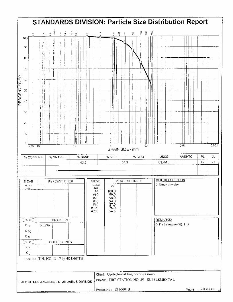
100
90
80
70
iz 1-1-1 60
PE
RC
EN
T F
50
40
30
20
10
STANDARDS DIVISION: Particle Size Distribution Report C4 C_
C_ O 9, O O tD
O O
O
—
,
,
- — 1,
--,—
-,
711c1 I nn 10 1 0 1 0.01 0.001
GRAIN SIZE - mm
`)/() COBBLES % GRAVEL % SAND % SILT % CLAY USCS AASHTO PL LL
45.2 54.8 CL-ML 17 21
SIEVE inches
size
PERCENT FINER
C.
GRAIN SIZE
060
D30
0 10
0.0879
_-- COEFFICIENTS
Cc
Cu
SIEVE number
size
PERCENT FINER
0
#4 100.0 #10 99.0 #20 98.0 #40 94.0 #60 87.0
#100 76.0 #200 54.8
SOIL DESCRIPTION
0 Sandy silty clay
REMARKS:
0 Field moisture (%): 11.7
Location T.H. NO. B-17 (//) 40 DEPTH
CITY OF LOS ANGELES - STANDARDS DIVISION
Client: Geotechnical Engineering Group
Project: FIRE STATION NO. 39 - SUPPLEMENTAL
Project No.: E170094B
Figure Bl7P,40

STANDARDS DIVISION: Particle Size Distribution Report
,_ . c c , , 4 ,., ...; O_
E' E 2 i :1 .! 1
90
80
Z
CC 70 1-1-1 60
Li 1--- z 50 W C) u i 40
30
10
0
100 1 - 0.,,,.
1
,
----
20
• 200 100 10 1
GRAIN 0 1 0.01 0.001
SIZE - mm
% COBBLES % GRAVEL % SAND % SILT % CLAY USCS AASHTO PL LL
56.9 43.1 SM NP
SIEVE inches size
PERCENT FINER SIEVE number
size
PERCENT FINER SOIL DESCRIPTION
0 Silty sand a
#4 #I0 #20 #40 #60
#100 #200
100.0 99.0 96.0 90.0 81.0 68.0 43.1
_ __---- GRAIN SIZE REMARKS:
D60 D30
D10
0.118 0 Field moisture (%): 8.7
---- -- COEFFICIENTS
Cc
Cu
Location T.H. NO. B-17 @ 45 DEPTH
CITY OF LOS ANGELES - STANDARDS DIVISION
Client: Geotechnical Engineering Group
Project: FIRE STATION NO. 39 - SUPPLEMENTAL
Project No.: E170094B Figure Bl7P45

STANDARDS DIVISION: Particle Size Distribution Report , , , ! .0 „„
„ , _ . ,2 , , T,
100
90
80
CC LI-I 60 Z E 1— z 50 UJ C) CY ai 40
30
20
10
I •
I 1 L t ,
•
70 Ii
I
— .. —
200 100 10 1
GRAIN 0 1 0.01 0.001
SIZE - mm
% COBBLES % GRAVEL % SAND % SILT % CLAY USCS AASHTO PL LL
32.8 67.2 ML 20 22
SIEVE inches size
PERCENT FINER SIEVE number
size
PERCENT FINER SOIL DESCRIPTION
0 Sandy silt 0
#20 #40 #60
#100 #200
100.0 99.0 96.0 90.0 67.2
-------- -----' _>-<—_____, GRAIN SIZE REMARKS:
060
030
D10
0 Field moisture (%): 13.1
---, -------- COEFFICIENTS
Cc
Cu
Location T.H. NO. B-17 @ 50 DEPTH
CITY OF LOS ANGELES - STANDARDS DIVISION
Client: Geotechnical Engineering Group
Project: FIRE STATION NO. 39 - SUPPLEMENTAL
Project No.: E170094B Figure B17P50


Fire Station #39 February 15, 2013
APPENDIX D
Standards Report of Subsurface Investigation (Contamination)
Dated August 8, 2012


CITY OF LOS ANGELES DEPARTMENT OF GENERAL SERVICES
STANDARDS DIVISION
. rfl
ri rn C:::
G) •t.-7) -,ff:',
FIRE STATION NO. 39 (CONTAMINATION)
LAB NO. 140-5917
W.0 NO. E170094B AUGUST 2012
GEOTECHNICAL SERVICES FILE: 12-002


Geotechnical Engineering G Standards on 06-04-12. drilling and sampling
ave the Notice to Proceed with the subsurface investigation to our Bureau was notified at least 48 hours prior to the ring location map is included in this report.
A:01MM AfrAraprit
'Y H. SOLO PrN,
CITY OF LOS ANGELES DEPARTMENT OF GENERAL SERVICES
STANDARDS 2319 DORRIS PLACE
LOS ANGELES, CA 90031 (213) 485-2242
fax (213) 485-5075 LAB. No. 140-5917 R EC' D 05-16-12 Nrrp 06-04-12 IZEP'T'D 08-08-12 To Gary Lee Moore
City Engineer Att'n: Christopher Johnson
Fire Station No. 39 (Contamination)
W.O. No. E170094B File No. 12-002
Report of
SUBSURFACE INVESTIGATION (CONTAMINATION)
Transmitted are the field logs of the subsurface investigation and chemical test results performed by Standards on the above-named project as requested by the Geotechnical Engineering Group. The descriptions on the "Log of Test Boring" sheets are based on field identification procedures and the classifications of soils are based on the Unified Soil Classification System, a copy of which is attached. The purpose of this investigation was to determine the extent, if any, of chemical contamination of the soils within the project area.
One test boring was drilled on this project with a truck-mounted Central Mine Equipment Model-75HT drill rig using six-inch conventional flight augers. "Undisturbed" samples were obtained from the test borings with a 2%-inch outside diameter (O.D.) by 2-inch inside diameter (I.D.) Split Spoon sampler lined with 1%8-inch inside diameter (I.D.) by 4-inch high brass tubes. The sampler was driven into the soil with the weight of a 300-pound drop hammer falling approximately 30 inches.
At the request of GEO, six soil samples were collected from the above named project to analyze for possible chemical contamination. The samples were analyzed in accordance with ELAP approved methods. The specific methods are listed on the data sheets.
Copies of the chain of custody and sample analysis results are attached to this report.
Services/Standa
RHS:JV:KSN:MNR:m

CITY OF LOS
DEPARTMENT OF G STANDARDS
2319 DORRIS
LOS ANGELES
(213) 4-2
ANGELES
ENERAL SERVICES DIVISION
PLACE
CA P3331
242
UNIFIED SOIL CLASSIFICATION SYSTEM
MAJOR DIVISIONS GROUP
SYMBOLS TYPICAL NAMES
COARSE
GRA INED
SOILS (More than 50% o f
material is
LABGER than
No.200 sieve size.)
GRAVELS (Little
(More than 50 %
of coarse fraction
is LARGER than
she 1,10.4
ieve size)
CLEAN --s ,' :,:4 1
GRAVELS or no fines)
uTu'v 4 • l.
14.'11
GW Well graded gravels, gravel-sand mixtures, little or no
fines.
•
,..
G p Poorly graded gravels or gravel-eand mixtures, little or
no fines.
GRAVELS
WITH FINES (Appreciable
amount of fin e: )
‘• ...
. GM Silt gravels, gravel-sand-silt mixtures.
/ • GC
,
Clayey gravels', gravel-sand-clay mixtures.
S ANDS
(More than 50%
of coarse fraction
is Stv1ALLER than
OW NO. it sitwo si,e)
CLEAN
SANDS (Little or no fines)
--
• W gr adorl sands, grayally SiilldS, kW', or no (inns,
fines.
S p Poorly graded Sands or gravelly S M1,41, little or no
SANDS
WITH RNLI'S (APP.,, i , ild.
runotint of fines)
•
sm Silty 11011 if fi , S 111.1-Silt IIIIXtllI(:S .
77/..;. .,-.Z/I'''
/..;>',..../..
Sc cl,,,, y sands, sand-clay mixtures.
FINE
GRAINED
SOILS (Mnra than 50% of
intster - itil ill
SMALLER than
No.200 sieve size:)
, SI LT S AND CLAY 'Y s
ct igiii,1 unlit LESS t11.1 !;;Ill ./////:-
///'./. / '/'
L_
_
Inorganic silts and very fine sands, rock flour, silty or
clayey fine sands or clayey gilt:; with slight plasticity.
iii,,,,,,i, ,:!,,, d
:)( 1,, 1. 1,1,1;,.iiii ;:l::::t.ii,:i.,r, (11 il,;!! .1-'
clays, sandy ays, silty clays la,,, , Ir,ari es.
0 L. Organic silts and ot gi tHi c Silty cl,,,, of low piiioicit y .
SILTS AND CLAYS ( Li quid limit GREATER than 50)
...-4
/
.
fvf li Inorganic !silt`:, I i IICilI2C011, (II I 11,1i (.111,if,IIIIS rin( ,,,,,,.1‘,/ or silty soils, ,last in silts.
//
/
7 / /
CH Inorganic clays of high plasticity, fat clays.
7/ - /7 7:/
OH Organic clays of medium to high plasticity, organic
silts.
HIGHLY ORGANIC SOILS '
k Pt Not mirl will,' Iiitillly oroirriic soils.
BOUNDARY CLASSIFICATIONS: Soils poss,,ssing characteristics of two groups 1(1(1 designated by
combinations of group syn -thols.
PARTICLE SIZE L I M1TS
SILT OR CLAY
SAND GRAVEL
COBBLES I BOULDERS FINE I MEDIUM COARSE FINE COARSE
No.2 0 0 No.4 0 No.10 No.4 3/4 in. 3 ii1. 1 2 in.
U.S. STANDARD SIEVE SIZE
Reference:
The Unified Soil Classification System, Corps of Engineers,
U.S. Army Technical Memorandum No..3-357, Vol. I, March 1 Et S.
(Revised April, 1 9 6 0)
11 ."....a.....-deatucw..,-....
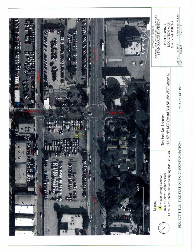

5
10
.15
20
25
3 C)
LOG OF TEST BORING LAB. NO.: 140- 5917 PROJECT: FIRE STATION NO. 39 BORING NO.: H-1 ELEVATION: 698' DRILLING DATE: 06/18/2012 (CONTAMINATION) BORING LOCATION: 58' N/o NCF Oxnard St & 54' W/o WCF Vesper Av DRILL RIG TYPE: CME-75HT using 6" diameter conventional flight augers DEPTH TO STANDING WATER: None DEPTH TO WATER SEEPAGE: None DRILLER: Cooksey LOGGER: Roth ENGINEER: None present
LEL (%)
OVA (PPM)
SOIL SYMBOLS, SAMPLER SYMBOLS AND BLOWS/INCHES
USCS Field Description qATION
i:) -1- 1--1 (ft)
0
0
0
0
0
0
0
0
0
0
0
0
0
0
4" AC pavement in poor condition 6" PCC pavement FILL MATERIAL. Brown silty fine-medium sand. Moist and loose. FILL MATERIAL. Brown silt with some fine-very fine sand. Moist and soft. Sample at 5' depth was not recovered, encountered red clay brick, moved hole 3' West & 1' South; encountered brick again, moved hole 2' South.
Density increased at 30' depth (likely native material) .
35
No free water. ---
Test Boring Location Coordinates: 34° 10' 46.70" North 118° 27' 04.07" West
CITY OF LOS ANGELES - STANDARDS DIVISION

KEY TO SYMBOLS Symbol
Strata
Description
symbols
AC pavement.
PCC pavement.
Silty sands, sand-silt mixtures
Inorganic silts and very fine sands, rock flour, silty or clayey fine sands or clayey silts with slight plasticity.
S oi l Samplers
Split Spoon, jar, vial
N()Les:
One exploratory boring was drilled on 06/08/2012 with a CME-75HT drill rig using 6" diameter conventional flight augers.
Free water was not encountered during the drilling of this project.
r,c)ring locations were provided by Geotechnical Services and verified by Standards.
Abbreviations used on logs: N/o = north of S/0 = south of E/o = east of W/o = west of CL = center line AC = asphalt concrete
OVA = organic vapor analyzer PPM = parts per million
NE = northeast NW = northwest SE = southeast SW = southwest PL = property line
PCC = Portland cement concrete LEL = lower explosive limit HT = high torque
NCF north curb face SCF south curb face ECF east curb face WCF west curb face
The stratification lines indicated on the boring maps and profiles represent the approximate boundary between material types and the transition may be gradual.
The materials, boundaries, and conditions have been established only at the boring locations, and are not necessarily representative of subsurface conditions elsewhere across the site. — —

GW
BOUNDARY CLASSIFICATIONS: Soils poss,,SSSIfIg characteristics of two groups ens de,,ignated by
combinations of group symbols.
SIZE L I M I S PARTICLE
COARSE
GRAVEL
FINE
No.10 No.4 No.200 No. , 0
U. S. STANDARD
12 in. 3/4 in. 3 in.
SIEVE SIZE
UNIFIED SOIL CLASSIFICATION SYSTEM*
MAJOR DIVISIONS GROUP
SYMBOLS TYPICAL NAMES
COARSE GRAINED
SOILS (More than 50% o
material is
LARGER than
No.200 sieve size; )
FINE GRAINED
SOILS (Moro than 50% of
mu teria) is
;.7;tAl\t_ LER titan
No.200 sieve cite)
GRAVELS (More than 50 %
of coarse fraction
is LARGER than
the'lVo.4
sieve size)
SANDS (More than 50%
of coarse fraction
is SMALLER than
the No.4
ninve size)
CLEAN GRAVELS
(Little or no fines)
GRAVELS WITH FINES
(Appreciahle
amount of fines)
CLEAN SANDS
(Little or no fines)
SANDS WITH FINE-
(Appreciahlo amount of fines)
Well graded grovels, gravel-sand mixtures, little or no
fines.
GP
Silt gravels, gravel-swirl-silt niixtures.
Clayey gravels, gravel-sand-clay rnixtures.
g ri,...bul r;ands, grwelly sands, little or no fines.
Poorly graded sands or gravelly Sande, little or no
sands, srind-Gilt mixtures.
C la ye y an t , CI y MI t t If CS .
Inorganic silts and very hoc; sands, rock flour, silty or
clayey fine sands or clayey silts with slight plasticity.
;,f ILA, to inu , 110in
clays, sawly clays, y (Joys, 11,111 ClayS •
silk, end organic low plasticity.
Inui Hlts, inica,eons li.- Thinaceoos smidy
nr silty sail:;, araSlI• ,ills.
Inorganic dayn Of l; 41k lilr,ticity, fat clays.
•
C) [_
MI I
CH
I S fi-\[\,1 D C I.CSS than 1311,
SILTS AND CLAYS (Liquid limit GREATER than 50)
Poorly graded gravels or gravel.sand mixtures, little or
no fines.
GM
GC
HIGHLY ORGANIC SOILS
Organic clays of fra,i11111 . 1 to Ilir,J11 plasticity, organic
silts.
Peat and other organic Pt
in., ....U.,. WV..., 24S,
Reference:
The Unified Soil Classification System, Corps of Engineers,
U.S. Army Technical Memorandum No, 3.357, Vol, I, Match r:?1,3,
fFievised April, 1560)
CITY OF 1,0S ANGELES
DEPARTMENT OF GENERAL SERVICES STANDARDS DIVISION
:Lill DORRIS PLACE
LOS ANGELES CA 0.031
(213) 4E5-2242
SAND
FINE 1 MEDIUM COARSE COBBLES I BOULDERS
SILT OR CLAY

June 08, 2012 July 10, 2012
Christopher Johnson, Group Manager Bureau of Engineering/Geotechnical Engineering Group
Curtis Gee, Civil Engineering Associate III Bureau of Engineering/Geotechnical Engineering Group
Form 6SISTD 911
Lab.#:
Received: Reported:
To:
Attn:
CITY OF LOS ANGELES
DEPARTMENT OF GENERAL SERVICES
STANDARDS DIVISION 2319 DORRIS PLACE
LOS ANGELES, CA 90031 (213) 485-2242
FAX (213) 485-5075 12-00510-01 to 06 FIRE STATION 39 W.O. E170094B
SAMPLE ANALYSIS RESULTS
At the request of the Bureau of Engineering's Geotechnical Engineering Group, six soil samples from Fire Station 39 were collected to examine possible chemical contamination. Selected samples were analyzed for heavy metals, volatile organic compounds (VOC), pesticides and polychlorinated biphenyls (PCB), semi-volatile compounds and total recoverable petroleum hydrocarbons (TRPH).
None of the samples exceeded the total threshold limit concentration (TTLC) or soluble threshold limit concentrations (STLC) specified in the California Administrative Code Title 22 regulations for any heavy metal.
The samples were analyzed in accordance with the California Department of Public Health's Environmental Laboratory Accreditation Program (FLAP) approved methods. The specific methods are listed on the data sheets.
The chain of custody and data sheets are attached.
Pay H. Solomon, Acting Director General Services/Standards
RHS:KK:CDW:MT:MC:cdw
E111

• • T
T L
C
Da
te D
ate
T
it
le 2
2 t
Sam
ple
d A
na
lyze
d M
et h
od
An
aly
s t
mg
/Kg
06
/08
/12
07
/02
/12
EP
A 6
01
0B
MC
500
mg
/Kg
06
/08
/12
07
/02
/12
EP
A 6
01
0B
MC
500
m
g/K
g 06/0
8/1
2 0
7/0
2/1
2 E
PA
60
10
B M
C 10
000
mg
/Kg
06
/08
/12
07
/02
/12
EP
A 6010B
MC
75. 0
m
g/K
g 0
6/0
8/12
07/0
2/1
2 E
PA
6010B
MC
100
mg
/Kg
06/0
8/1
2 0
7/0
2/1
2 E
PA
6010B
MC
2500
m
g/K
g N
/A N
/A E
PA
7196A
N
/A
500
mg
/ Kg
06
/08
/12
07/0
2/1
2 E
PA
6010B
MC
800
0 m
g/K
g 0
6/0
8/1
2 0
7/0
2/1
2 E
PA
6010B
MC
2500
m
g/K
g 0
6/0
8/1
2 0
7/0
2/1
2 E
PA
60
10B
M
C 10
00
mg
/Kg
06
/08
/12
07
/02
/12
EP
A 7
47
1A
MC
20. 0
m
g/K
g 06/0
8/1
2 0
7/0
2/1
2 E
PA
6010B
MC
3500 .
COO
0 0 0
O 0 0 0 0 0 0 0
LO
•
it 0
co
0-) O 0 N-
o UJ
▪ • •
a
H a)a' • E!
0 co
cr)
0 0 2 z C
co
C; CO
Lu
co O
O CO
0 Lu
co O
O co
EP
A 6
01
0B
EP
A 6
010B
EP
A 6
01
0B
EP
A 6
010B
EP
A 6
010B
EP
A 6
010B
co
a_
0 .c
ti
Lu
CV CV
0
N- O
CV CV
0 ti O
cv
O
0
CR1
0
c■1 O
O ti O
O
ti O
O
N- O
O
0 0
ti O
CD
0
O
O
0
z 0
N- 0 N- o
0 ti 0
N- 0 0 O 0
V
a O cri
CV
co O CO 0
CV CV
00 0
cv
00
CV
0
CO O
CV
03 0
O
CV ‘-- co
-63 0-3 N- 8 8
O
0
Coo O
CD
03 O
0
co 0
0
0 0 z 0 0 0 O 0 O cO
0
O cs) 0
CO 0 a)
0) C
a)
0 C/)
C1)
O CO
0 0 CO
a)
a)
Co
0
.
Cn a)
0
H H a)
a)
_c
a)
CO Cr)
0 0 0 0 0 0 O
0)
0)
E
0)
0)
E
0)
0)
E
0)
0) E
0)
0) E
0)
0) E
0)
e) E
0)
0) E
0)
0) E
0)
0)
E
0)
0) E
0)
0) E
0)
0) E
0)
0) E
0)
03 E
0)
0) E Un
its C 0
0) E
0) E
No t
Ana
lyze
dApp
lica b
le
12- 0
510-
05E
O N N- N- a z
a a co U)
a a z
a z
a z
a CO 0 CV c0
z
4
12- 0
510-
04E
O CV z
ti
0)
LC) CO ti
N- CO CO
a a a a CO
CY) LC)
a a a a z
N 0)
CO; z z
z
O
E a) 0
0) . 0
0
0 • a) a) (1) E (2
E o
c-v C (.1 eL
= o (r) 92 ..c 0
a 7) F- Z W
CD L-
0 •- X c E co 0
tj
m 0 ca.
• z CU r-
CX 17-
LLI
O O
to
h CY) 00
CO CD N a a a a O
CO
N-. a a a a z 00 CO z .c
0 a) O
C9 er) cY) co It
c O 0
O (jj . _
a.
•
LL
CA a)
a) -0 E • < Z
O
••-' 0
'ET (-) 0
Q.
O (4,
0 ..0 C 4., CO
E Ca
a a z
a a z
a a a z
a z
a a a a a
z
a z
a a a z z
O O
co co O
O
0 O 0 0
CY) CO
co CO
O O
CO C'.)
0 –J O O
O O
0 CO CO
O O O co 0 O 0 CO O O
Sam
ple
Des
crip
t ion
CO N- O N-
La
bor
ato
ry I
. D.
CO 0 H
C
z •■=
2
0
E
2E-
C a) 0 0 >,
U) a)
co C
C O E C
0 C a) C/)
(77.) CL
0
-E3 C co
CU
0 z C a) Cll
CO -0 0
E2 CU
Co
a CD
co
-o CO 0
0
N
CO 0.)
_J a)
co F-
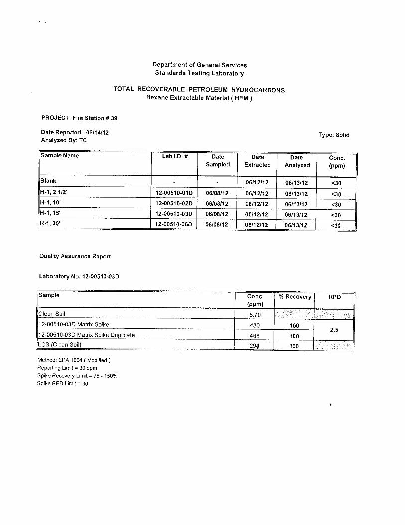
Department of General Services Standards Testing Laboratory
TOTAL RECOVERABLE PETROLEUM HYDROCARBONS Hexane Extractable Material ( HEM )
PROJECT: Fire Station # 39
Date Reported: 06/14/12 Analyzed By: TC
Type: Solid
Sample Name Lab I.D. # Date Sampled
Date Extracted
Date Analyzed
Conc. (ppm)
Blank - - 06/12/12 06/13/12 <30
H-1, 2 1/2' 12-00510-01D 06/08/12 06/12/12 06/13/12 <30 H-1, 10' 12-00510-020 06/08/12 06/12/12 06/13/12 <30 H-1, 15' 12-00510-03D 06/08/12 06/12/12 06/13/12 <30 H-1, 30' 12-00510-06D 06/08/12 06/12/12 06/13/12 <30
Quality Assurance Report
Laboratory No. 12-00510-03D
Sample
Conc.
(ppm)
5.70
% Recovery RPD
Clean Soil
12-00510-03D Matrix Spike
480
100 2.5
12-00510-03D Matrix Spike Duplicate
468
100
LCS (Clean Soil)
294
100
Method: EPA 1664 ( Modified )
Reporting Limit = 30 ppm
Spike Recovery Limit = 78 - 150% Spike RPD Limit = 30

City of Los
VOLATILE ORGANIC COMPOUNDS
Project:FIRE STATION 39
3eles, Dept of General Services, Standards Te rg Laboratory
mg/kg (ppm) Laboratory ID No . Blank 12-00510-04A 12-00510-05A RL Sample Location H-1, 20' H-1, 25' Low Sample Date 6/8/12 6/8/12 Level Analysis Date 6/13/12 6/13/12 6/13/12
Analysts Initials MG MG MG
Analysis Method Low Level Low Level Low Level
Multiplier 1.0 1.0 0.93 X Multiplier
Dichlorodifluoromethane
Chloromethane 0.0032
0.0016 Vinyl chlonde
Bromomethane 0.0024
Chtoroethane
Trichiorofluoromethane
. •
•
•
'
...,........,...,
0.0024
0.0024 Ethanol
1,1-Dichloroethene
*
*
•
'
*
* 0.80
0.0012 Methylene chloride
2-Methyl-2-propanonol (TBA)
*
•
*
•
*
* 0.0080
0.0075 trans-1,2-Dichloroethene
2-Methyl tert-butyl ether (MTBE) *
*
•
'
•
* 0.0008
0.0010 1,1-Dichtoroethane
Diisopropylether (DIPE)
*
"
•
*
*
• 0.0008
0.0010 2-Ethoxy-2-methylpropane (ETBE)
2,2-Dichloropropane * •
'
•
• 0.0010
0.0012 cis-1,2-Dichloroethene
2-Butanone (MEK)
*
"
•
0.0038
•
0.0040 0.0008
0.0020 Bromochlorornethane
Chloroform
*
• * 0.0008
0.0008 1,1,1-Trichloroethane
2-Ethoxy-2-methylbutane (TAME)
*
*
•
*
•
* 0.0008
0.0010 Carbon tetrachloride
1,1-Dichloropropene
•
*
* *
* 0.0012
0.0012 Benzene
1,2-Dichloroethane
* .
0.0017 0.0024 0.0008
0.0008 Trichloroetliene
1,2-Dichloropropane *
*
'
*
• 0.0008
0.0012 Dibrornomethane
Bromodichloromethane
* *
•
* * 0.0008
0.0008 2-Chlornethyl vinyl ether
cis-1,3-Dichloropropene
*
* •
*
* 0.0015
0.0008 4-Methyl-2-pentanone (MIBK)
Toluene
*
*
'
0.0017
• '
0.0017 0.0010
0.0008 trans-.1,3-Dichloropropene
1,1,2-Trichloroethane,
* ' 0.0008
0.0008 Tetrachloroethene
1,3-Dichloropropane *
U.024 0.0'10 0.0012
0.0008 Dibromochloromethane
1,2-Dibromoethane
• *
*
*
*
* 0.0008
0.0008 Chtorobenzene
1,1,1,2-Tetrachloroethane......
•
* .
*
*
•
• 0.0008
0.0008 ,erizene
meta & para-Xylenes 0.0008
0.0016 ortho-Xylene 0.0008 Styrene 0.0008 Bromoforrn 0.0012 IsoproPylbenzene 0.0008 1,1,2,2-Tetrachloroethane 0.0008 Bromobenzene 0.0008 1,2,3-Trichloropropane 0.0008 n-Propylbenzene 0.0008 2-Chlorotoluene 0.0008 1 ,3,5-Trirnethylbenzene 0.0008 4-Chlorotoluene 0.0008 tert-Butylbenzene 0.0008 1,2,4-Trimethylbenzene 0.0008 sec-Butylbenzene *
0.0008 1,3-Dichlorobenzene 0.0008 p-Isopropyltoluene 0.0008 1,4-Dichlorobenzene 0.0008 n-Butylbenzene 0.0008 1,2-Dichlorobenzene 0.0008 1,2-Dibromo-3-chloropropane 0.0012 1,2,4-Trichlorobenzene 0.0008 Hexachlorobutadiene 0.0012 Naphthalene 0.0008 1,2,3-Trichlorobenzene 0.0008 Total 0.031 0.018
QUALITY CONTROL
Surrogate Compounds % Recovery % Recovery Dibrornofluoromethane 103 105 103 84.1 - 118 Toluene-d8 102 99.8 98.9 83.7 - 119 4-Bromofluorobenzene 97.3 101 102
73.9 - 130
A. Method: EPA Method 82608
B. Instrument 92: Hewlett-Packard 5890 with 5971 Sakes Mass-Selective Detector
C. Column: Rtx-624, 0.53 I D., 3.0 Micron Thickness, 75 Meters.

City of Los Angeles, dt of General Services, Standards Testing L--oratory
SEMI-VOLATILE ORGANIC COMPOUNDS (mg/Kg)
Project: Fire Station #39
Laboratory ID No. Method Blank 12-00510-04D 12-00510-05D RL Sample Location - H-1; 20' H-1; 25' Soil Date Sampled - 06/08/12 06/08/12 mg/Kg Date Extracted 06/18/12 06/18/12 06/18/12
Analysis Date 06/18/12 06/18/12 06/18/12
Analysts Initials MG MG MG
Multiplier 1.0 1.0 1.0 X Multiplier
n-Nitrosodimethylamine . * • 0 . 457 Phenol ' 0.714 bis-(2-Chloroethyl)ether • • * 0.457 2-Chlorophenol * • • 1.140 bis-(2-Chloroisopropyl)ether ' ' • 0.457 n-Nitroso-di-npropylamine . ' • 0.309 Hexachloroethane . * * 0.457 Nitrobenezene * * * 0.309 Isophorone * * *
0.309 2-Nitrophenol * ' * 0.714 2,4-Dimethylphenol * * * 0.714 bis-(2-Chloroethoxy)methane * *
0.309 2,4-Dichlorophenol * * * 0.714 4-Chloro-3-methylphenol « " * 0.714 Hexachlorocyclopentadiene * * *
2.240 2,4,6-Trichlorophenol * * 0.714
2-Chloronaphthalene * * 0.309
Dimethylphthalate * * * 0.309
Acenaphthylene . . 0.457
2,6-Dinitrotoluene * * * 0.309
Acenaphthene * * * 0.457
2,4-Dinitrophenol * * 2.14
4-Nitrophenol . * * 1.430
2,4-Dinitrotoluene * * 0.309
Fluorene * a * 0.309
Diethylphthlate * * * 0.309
4-Chlorophenyl phenyl ether * * 0.309
4,6-Dinitro-2-methylphenol * * ' 0.714 N-Nitrosodiphenylamine *
0.309
Azobenzene * * * 0.309
4-Bromophenyl phenyl ehter * * * 0.309
Hexachtorobenzene * * 0.309
Pentachlorophenol * * * 2.210
Phenanthrene * * 1.19 0.309
Anthracene * ii, 0.309
Di-n-butylphthalate * * * 0.309
Fluoranthene * * 2.81 0.309
Benzidine * * 1.430
Pyrene * * 2.33 0.309
Butylbenzylphthalate . * 0.309
Benzo(a)anthracene * * 1.25 0.309
3,3'-Dichlorobenzidine * * 1.140
Chrysene * ' * 1.10 0.309
bis-(2-Ethylhexyl)phthalate * 0.309
Di-n-octylphthalate * * * 0.309
Benzo(b)fluoranthene * 1.50 0.309
Benzo(k)fluoranthene * * 0.491 0.309
Benzo(a)pyrene * 1.21 0.309
Indeno(1,2,3,c,d)pyrene * * 0.473 0.309
Dibenzo(a,h)anthracene . 0.309
Benzo(g,h,i)perylene * * 0.464 0.309
2-Methylphenol * 0.714
4-Methylphenol * . ' 0.714
2,4,5-Trichlorophenol * w * 0.714
Total • * 12.8
QUALITY CONTROL
Surrogate Compounds GJtlitOf
Limits
2-Fluorophenol 101 107 101 °,4Racovory 20.8 - 125
Phenol-d6 67.7 73.1 69.4 8.70 - 107 Nitrobenzene-d5 99.5 107 98.3 26.2 - 126 2-Fluorobiphenyl 99.9 105 94.2 20.9 - 129 2,4,6-Tribromophenol 121 126 117 1.40 - 160 Terphenyl-d14 105 110 92.2 14.3 - 139
A. Method: EPA Method 82708
8. Instrument: Agilent 6890N GC with 59758 Mass-Selective Detector
C. Column: DB-5.625, 0.25 mm I.D., 0.25 micron Film Thickness, 30 Meters.
RL: Reporting Limit Below Reporting Limit

City of Los Angeles, Dept of General Services, Standards Testing Laboratory
PESTICIDES & POLYCHLORINATED BIPHENYLS (PCB'S) Project: Fire Station # 39
Laboratory I.D. Soil Blank 12-00510-04D Reporting Sample Location H-1 @ 20' Limit Sample Date 06/08/12 Analysis Date 06/14/12 06/14/12 Analysts Initials MT MT Alpha-BHC * * 0.010 Gamma-BHC * * 0.010 Beta-BHC * * 0.010 Heptachlor * *
0.010 Delta-BHC * * 0.010 Aldrin * * 0.010 Heptachlor Epoxide * * 0.010 Alpha-Endosulfan * * 0.010 4,4'-DDE * *
0.010 Dieldrin * 1 * 0.010 Endrin * *
0.010 4,4'-DDD * *
0.010 Beta-Endosulfan * *
0.010 4,4'-DDT * *
0.010 Endrin Aldehyde * *
0.010 Endosulfan Sulfate * *
0.010 Endrin Ketone * *
0.010 Methoxychlor * *
0.010 Chlordane * *
0.10 Toxaphene *
0.50 Arochlor 1016 * * 0.20 Arochlor 1221 * * . 0.20 Arochlor 1232 * *
0.20 Arochlor 1242 * *
0.20 Arochlor 1248 * *
, 0.20 Arochlor 1254 * * 0.20 Arochlor 1260 *
* * 0.20
Total *
QUALITY CONTROL
Surrogate Compound . Control Limits (% Recovery)
Tetrachloro-m-xylene 36.2 20.0 13.6 - 109 Decachlorobiphenyl 177** 44.4 14.7 - 121
A: Method: EPA Method 8081A B. Instrument: Hewlett-Packard 5890 GC with Dual Electron Capture Detectors. C. Column: HP-35, 0.53 I.D., 30 Meters and DB 1701P, 0.53mm ID, 30 Meters ** second surrogate co-eluted with a contaminant

City of Los Angeles Department of General Services Standards Testing Laboratory
Quality Assurance Report
Laboratory Number: 12-00510-04A
Date Analyzed 06/13/12 Analyzed By: MG
Volatile Organic Compounds
Matrix: SOIL
Concentration in u /K b Compound Sample
Result
Matrix Spike Matrix Spike Duplicate Control RPD RPD
Limit Conc. Result (3/0 Rec Conc. Result % Rec Limit 1,1-Dichloroethene 0.00 100 79.3 79.3 100 85.8 85.8 58.9 - 153 7.9 18 Methylene Chloride 0.00 100 96.5 96.5 100 99.7 100 74.0 - 153 3.3 14 Methyl tert Butyl Ether (MTBE) 0.00 100 99.7 99.7 100 102 102 67.4 - 119 2.3 15 1,1-Dichloroethane 0.00 100 96.6 96.6 100 102 102 77.3 - 128 5.4 15 Chloroform 0.00 100 104 104 100 112 112 80.9 - 129 7.4 12 1,1,1-Trichloroethane 0.00 100 90.2 90.2 100 95.2 95.2 66.9 - 122 5.4 15 Benzene 0.00 100 97.8 97.8 100 102 102 74.2 - 123 4.2 12 1,2-Dichloroethane 0.00 100 103 103 100 106 106 81.1 - 118 2.9 8.8 Trichloroethene 0.00 100 97.6 97.6 100 102 102 71.8 - 122 4.4 13 Toluene 0.00 100 103 103 100 102 102 71.6 - 121 1.0 13 Tetrachloroethene 24.5 100 102 77.5 100 107 82.5 70.4 - 122 4.8 22 Chlorobenzene 0.00 100 100 100 100 102 102 71.2 - 119 2.0 13 1,4-Dichlorobenzene 0.00 100 94.2 94.2 100 92.6 92.6 67.9 - 116 1.7 19
A. Method EPA 8260
B. Instrument#1: Hewlett-Packard 5890 w/5971 Mass-Selective Detector C. Column: RTX-624, 0.53 mm I.D., 3.0 micron Film Thickness, 75 Meters

City of Los Angeles Department of General Services Standards Testing Laboratory
Quality Assurance Report
Lab Number: 12-00510-05D
Date Extracted: 06/18/12 Date Analyzed 06/18/12 Analyzed By: MG
Semi-Volatile Organic Compounds
Matrix: Solid
Concentration in ug/Kg (ppb)
Compound Sample
Result
Matrix Spike Matrix Spike Duplicate Control
Limit
RPD RPD Limit Conc. Result % Rec Conc. Result % Rec
Phenol 0.00 100 92.1 92.1 100 83.6 83.6 30.7 - 120 9.7 27 2-Chlorophenol 0.00 100 88.7 88.7 100 80.8 80.8 26.3 - 124 9.3 27
1,4-Dichlorobenzene 0.00 50.0 40.7 81.4 50.0 37.1 74.2 26.0 - 102 9.3 30
N-Nitroso-di-n-propylamine 0.00 50.0 48.9 97.8 50.0 45.5 91.0 36.9 - 128 7.2 32
1,2,4-Trichlorobenzene 0.00 50.0 44.2 88.4 ' 50.0 40.8 81.6 34.5 - 111 8.0 26
4-Chloro-3-methylphenol 0.00 100 95.8 95.8 100 90.7 90.7 32.8 - 129 5.5 34
Acenaphthene 0.00 50.0 45.7 91.4 50.0 43.1 86.2 35.4 - 117 5.9 31
4-Nitrophenol 0.00 100 103 103 100 99.8 99.8 3.9 - 156 3.2 34
2,4-Dinitrotoluene 0.00 50.0 42.5 85.0 50.0 47.2 94.4 40.4 - 126 10 29
Pentachlorophenol 0.00 100 116 116 100 113 113 21.2 - 143 2.6 37
Pyrene _ 58.1 50.0 94.2 72.2 50.0 54.4 7.40 21.9 - 140 54 26
A. Method EPA 8270B B. Instrument: Agilent 6890N GC with 5975B Mass-Selective Detector C. Column: DB-5.625, 0.25 mm I.D., 0.25 micron Film Thickness, 30 Meters
RPD - Relative Percent Difference

City of Los Angeles Department of General Services Standards Testing Laboratory
Quality Assurance Report
Lab Number: Clean Soil Spk for 12-00510-04D & 05D
Date Extrated: 06/18/12 Date Analyzed: 06/18/12 Analyzed By: MG
Semi-Volatile Organic Compounds
Matrix:
Concentration in ug/Kg (ppb)
Compound Sample
Result
Matrix Spike Control
Limit Conc. Result % Rec Phenol 0 100 84.5 84.5 39.0 - 110 2-Chlorophenol 0 100 81.5 81.5 44.4 - 118 1,4-Dichlorobenzene 0 50.0 40.0 80.0 43.8 - 105 N-Nitroso-di-n-propylamine 0 50.0 46.2 92.4 51.7 - 120 1,2,4-Trichlorobenzene 0 50.0 42.6 _ 85.2 45.8 - 110 4-Chloro-3-methylphenol 0 100 91.6 91.6 42.5 - 123 Acenaphthene 0 50.0 42.7 85.4 45.6 - 107 4-Nitrophenol 0 100 94.9 94.9 17.0 - 158 2,4-Dinitrotoluene 0 50.0 48.2 96.4 49.4 - 126 Pentachlorophenol 0 100 105 105 30.3 - 144 Pyrene 0 50.0 45.7 91.4 43.4 - 126
A. Method EPA 8270B B. Instrument: Agilent 6890N GC with 5975B Mass-Selective Detector C. Column: DB-5.625, 0.25 mm I.D., 0.25 micron Film Thickness, 30 Meters
RPD - Relative Percent Difference

City of Los Angeles Department of General Services Standards Testing Laboratory
Quality Assurance Report
Lab Number: 12-00510-04
Date Extracted: 06/13/12 Date Analyzed 06/14/12 Analyzed By: MT
Pesticides
Matrix:
Soil
Concentration in ug/kg (ppb)
Compound Sample Result
Matrix Spike Matrix Spike Duplicate Control
Limit
RPD RPD Limit Conc. Result % Rec Conc. Result % Rec
g-BHC 0.00 20.0 5.44 27.2 20.0 5.66 28.3 14.5 - 140 4.0 32
Heptachlor 0.00 20.0 4.65 23.3 20.0 4.87 24.4 12.1 - 136 4.6 28
Aldrin 0.00 20.0 5.45 27.3 20.0 5.52 27.6 18.7 - 133 .._ 1.3 29
Dieldrin 0.00 50.0 16.9 33.8 50.0 16.2 32.4 18.6 - 147 4.2 30
Endrin 0.00 50.0 18.8 37.6 50.0 17.7 35.4 20.4 - 158 6.0 30
4,4' DDT 0.00 50.0 17.9 35.8 50.0 17.1 34.2 14.7 - 142 I 4.6 41
A. Method EPA8081A/8082 B. Instrument: Hewlett-Packard 5890 GC with dual Electron Capture Detectors.
C. Columns: DB-35MS, 0.32mm, 30 meters; DB-XLB, 0.32mm, 30 meters.
RPD - Relative Percent Difference

LABORATORY ABBREVIATIONS
ASTM American Society for Testing and Materials
BNA Base-Neutral/Acid Extractables
BOO Biochemical Oxygen Demand
COC Chain of Custody
DRO Diesel Range Organics
ECD Electron Capture Detector
ECF East Curb Face
ELAP Environmental Laboratory Accreditation Program
EPA Environmental Protection Agency
FID Flame Ionization Detector
Grams
GC Gas Chromatograph
GC/MS Gas Chromatograph/Mass Spectrometer
GRO Gasoline Range Organics
GSD General Services Division
HEM Hexane Extractable Material
ICP Inductively Coupled Plasma
KG Kilograms
L Liter
LCS Laboratory Control Sample
MBAS Methylene Blue Active Substances
MDL Method Detection Limit
MG Milligrams
ML Milliliter
MS Matrix Spike
MSD Matrix Spike Duplicate
NA Not Applicable
NCF North Curb Face
ND Not Detected
PAT Purge and Trap
PCB Polychlorinated Biphenyls
PPB Parts Per Billion
PPM Parts Per Million
PRG Preliminary Remediation Goals
QA Quality Assurance
QC Quality Control
RL Reporting Limit
RPD Relative Percent Difference
SCF South Curb Face
SM Standard Methods
STLC Soluble Threshold Limit Concentration
TCLP Toxicity Characteristic Leaching Procedure
TPH Total Petroleum Hydrocarbons
TRPH Total Rqcoverable Petroleum Hydrocarbons
TTLC Total Threshold Limit Concentration
VOC Volatile Organic Compounds
WCF West Curb Face
WET Waste Extraction Test

• .r,) -0 0 (30 1
a)
0 >_. u c C.) c) so 2 s)
c r j CL
o
.....
a) 3-
0 C C)
CC
. . >
a)
C 0
(_) -0 a) a_ („)
ir-\\ Li)
C 0
L- 0 0) 0
43
U.
E (1.)
r .0
11 L 9_ I 1
(`) a) CsA
<9 t--
a)
1".
0 J
0
(
QJ
E 0 C a)
CC
Ic
0
a) 0
0.
("I j •••• , j , I - • , 5
1 o 'C- t., .-- J..... C.)
0 P <

Con
tain
er
C C4 ("A (N C•4
Cs, iN
D D 0 0 o u u .E
• - ca ,- o (N c_ a)
0 .0
ci
CL
a E a)
N
0
I ,1
0
0
0
IL
I 1 : / al :!: ! :
ci
0 C) C
C)

Sam
ple
Ma
trix
: S
Cl)
CO
0 C CO
VI
CO
C!)
C CO
Cf)
Tit
le 2
2 T
TL
C (
All
Ele
men
ts)
i .0
p> Cd
! 0
O
O
5035
Sam
ple
Co
llec t
ion
To
tal H
ydr
ocar
bons
by
Gra
vim
e tr i
c
CCU Q)
E a)
CO
V
a) 0
. 0
• . • •
N
C
CCS
0
0
0 0 of)
•E
C.)
•'0'
C.)
r
U ■ID
CO
O
4-4
• ■•••4
—
C.) 7)
U
CO
0
-0
0 (.) 0 0 0
U
.5
cr, c-4
0
1 +6,
U 0 Cal
,-,''' CO
0,0 ,r)
:÷c C • -3 i-,..
0 7 7-.1- ,. . 0 0
t---' ,t' 8 o
0
0 -0 -0
0 up 0 0
, z 0 0
1
CO 0° 04
4 •E c, I '' cid,
•
0 CD CI
e-.-4 N •,,I. ,
;•Cl 71
CD >. .-I 2) CD .. , ..o u-4 . •—
cp e) t . (1) H 0
d . 4,1 .,;"( U
re•-4 (... o CI., iii VD
(..) 'CI "a' '-'
(L) CZ -a 4.--1 1/4' C") --, 4.-j(r)
C-) '-c)
Cli
ent B
ott
le?
12- 0
0510
- 02
• 0)
0 Cr-)
UC.)
PI) 4.1
V
U•
12- 0
0510
-04
12- 0
0510
- 03
Tue
s day
, Ju
ly 1
0, 2
012
Sam
ple
Ma
trix
: S
FIR
E S
TA
TIO
N #
39
C•••" • CL)
0
U•
12- 0
0510
- 01

Sam
ple
Ma
trix
: S
5035
Sam
ple
Co
llec t
ion
Tit
le 2
2 T
TL
C (
Al l
Ele
men
ts)
a) z
H
a)
a -0
-0
0
0 0 C))
a
a
•
•
a)
H
0
U
ral
C El FIR
E S
TA
TIO
N #
39
Cli
ent B
ott
le?
■.0 ;
1 0 j v-4 C
lien
t Bo
ttle
?
.11
C?
N 12- 0
0510
- 06
N 12- 0
0510
- 05
P P
roj
12- 0
0510
- 04A
Tue
s day
, Ju
ly 1
0, 2
012


Fire Station #39 February 15, 2013
APPENDIX E
Contingency Contaminated Material Recommendations


CONTINGENCY CONTAMINATED MATERIAL RECOMMENDATIONS
The following recommendations apply to handling and disposing of stained or hydrocarbon-contaminated soils should they be encountered during site excavations, particularly at the 20-25 ft depth near the discovered cesspit structure.
Excavation of Contaminated Soils
The soils which have visible staining or an odor should be tested in the field by the contractor or qualified environmental subcontractor with an organic vapor analyzer (OVA) for volatile components, which require additional considerations in their handling. Soil with OVA readings exceeding 50 ppm volatile organic compounds (probe held 3 inches from the excavated soil face), or which is visibly stained or has a detectable petrochemical odor should be stockpiled by the Contractor separately from non-contaminated soils. The stockpiles should be barricaded near the excavation area, away from drainage areas or catch basins, on an impermeable plastic liner (6 mil nominal thickness and tested at 100 psi strength). Caution must be taken to separate any contaminated soil from the remainder of the excavated material. If only a small amount of contaminated soil is encountered, it may be drummed in 55-gallon steel drums with sealing lids.
The soil will then be sampled in a random and representative manner. To establish waste classification, samples will then be analyzed for Total Recoverable Petroleum Hydrocarbons (TRPH), volatile organics (VOC), Semi-volatile Organic Compounds (SVOCs, which were found in the exploration), Title 22 heavy metals, reactivity (pH), corrosivity and toxicity. The number of samples will depend upon the volume of material removed, one sample for approximately every ton of soil. Storage space available at the site and neighborhood sensitivity will determine the amount of soil that can be stockpiled.
If volatile compounds are present at concentrations exceeding 50 ppm, an AQMD permit will be required, which most likely will require control of vapor, such as covering the stockpiles with plastic sheeting or wetting with water or a soap solution. The Contractor shall obtain all permits.
Suspected contaminated soil samples can be taken to a State-certified environmental laboratory or tested in the field with a mobile lab and technician using infrared spectrometry with EPA Method 1664 for TRPH. Materials with elevated levels of TRPH, metals or other regulated contaminants will require handling by workers who have been adequately trained for health and safety aspects of hazardous material handling.
Removal and Classification of Excavated Soil
Any contaminated material (soil, asphalt, brick, burned material, concrete, or debris) that is to be hauled off the site is considered a "waste product" and must be classified as hazardous or nonhazardous waste under all criteria by both State and Federal Codes prior to disposal. If the waste soil or other material is determined hazardous, a hazardous waste manifest will prepared by the Contractor or its qualified representative

and the material transported to an appropriate class of facility for recycling or landfill disposal by a registered hazardous material transporter. If the soil is nonhazardous but still exceeds levels that can be returned to the excavation, a less costly nonhazardous transporter and soil recycling facility may be used if no hazardous constituents are present above their respective action levels.
The Bureau of Contract Administration Inspector for the project shall be notified of all contaminated material removals, and will document all quantities, help insure soil segregation and ensure copies of signed manifests are retained for the City records.
Currently, there are no established regulatory limits or threshold values whereby soil with TRPH only can be classified as hazardous, although the California Code of Regulations (CCR) Title 22 provides limits for the volatile hydrocarbon constituents (including solvents), PCBs and metals. Therefore, until new criteria are released by the State or Federal agencies, soil levels of 100 ppm TRPH (crude oil, waste oil and diesel), 10 ppm gasoline, and 1/50/50/50/ ppm benzene, toluene, ethylbenzene and xylenes, respectively, are proposed. Soil contaminated with hydrocarbons at values less than these values may be backfilled, used for fill or paved over. A soil recycling facility should accept the material containing TRPH, assuming it is not hazardous due to metals or other contaminants, at a cost of $40 to $50 per ton. Depending upon the results of the sampling, this soil material is recycled into building foundation material, road pavement, landfill cover, etc. A recycling facility is preferred to landfills, as the latter raise future liability issues for the City should the landfill require remediation. GEO has a list of addresses and telephone numbers of local recyclers available. A Class III (municipal) landfill may also accept soils with only TRPH contamination above 1,000 but below certain levels specified by the Los Angeles Regional Water Quality Control Board, upon approval of an application (Report of Waste Discharge) with that agency. The disposal costs at a Class III landfill are approximately $35 per ton. All excavated material moved offsite must be manifested, transported by a registered hauler, and disposed of in the proper class landfill or recycler. Transportation costs to the Class II or III facilities are estimated at $5 per ton within the Los Angeles area. These facilities can be contacted ahead of time regarding their acceptance of SVOCs.
Health and Safety Issues
The contractor shall be licensed for hazardous materials handling and hauling or have a qualified licensed subcontractor on call. The workers exposed to or handling contaminated soils shall have sufficient health and safety training, consistent with OSHA Hazardous Waste Operation Standards (29 CFR 1910.120), and Cal-OSHA "Hazardous Waste Operations & Emergency Response" (8 CCR 5192).
The contractor, qualified subcontractor or an industrial hygienist shall prepare a site-specific health and safety plan. The plan shall appoint a site safety officer and establish responses to heavy metals, solvents, SVOCs and petroleum hydrocarbons, which may be encountered during excavations. Trapped pockets of methane and hydrogen sulfide gas and areas of low oxygen are common in excavations of this area, and are usually mitigated in confined excavations with proper monitoring and ventilation. The plan should specify particular action levels for each contaminant found during exploratory drilling and suspected to occur along the alignment and provide guidelines for personal

safety and public protection, including monitoring and appropriate personal protective equipment needed on the jobsite during all phases of excavation of the project. The responsibility for maintenance and calibration of monitoring gear should be specified. The goal is to prevent health-significant inhalation and dermal exposure to hydrocarbon-SVOC- or metal-contaminated soils, explosions and fires and to provide methods of decontaminating workers and equipment if contamination levels exceed those cited in the plan. Preventing unauthorized entry into the work and stockpile areas shall be included.


Fire Station #39 February 15, 2013
APPENDIX F
Probabilistic Seismic Hazard Analyses


0 0
0 0 0
0 0 0
.11111■1 0
0 0
.11.1.11■1
•■••■•■■
Lf) T-1
.1.11■■■
0 0 0 0
(say() poped Luniej

75 yrs 100 yrs
PROBABILITY OF EXCEEDANCE BOORS ET AL(1997) (250)
•
•
25 yrs 50 yrs Ity
100
90
80
70
ID 60
2 50
a) 40 0
-t3 30 a)
20
10
0
0.00 0.25 0.50 0.75 1.00 1.25 1.50 Acceleration (q)

.11.1.1■11
.1. • II■1.1
■■•
0
LC) C\1 O
0 0
0 0 0 0 0
0 0 O O
0 0 0
0 o
(sJA) poped wniej

75 vrs 100 yrs
PROBABILITY OF EXCEEDANCE BOZ. ET AL.(1999)HOR PS COR
•
25 yrs 50 yrs
•
■
Exc
eeda
nce
Pro
bab
ility
(%
)
100
90
80
70
60
50
40
30
20
10
0
0.00 0.25 0.50 0.75 1.00 Acceleration (q)
1.50 1.25

0
Lc)
LI)
O
0 0 O
••■■••■•■
•••■■■•■■
••■■•••.
(sJA) poped
0 O 0 0
O O 0
O O O 0 0
0 O

100
90
80
70
60
50
40
30
20
10
0
Exc
eed
ance
Pro
babi
lity
( %)
75 yrs 100 yrs
PROBABILITY OF EXCEEDANCE SADIGH ET AL. (1997) DEEP SOIL
25 yrs 50 yrs ■
0.00 0.25 0.50 0.75 1.00 1.25 1.50 Acceleration (g)

CALIFORNIA FAULT MAP Fire Station 39
11 00
1000—
900 —
800 —
700 —
600 —
500 —
400 —
300
200 —
100—
0
-100
-400 -300 -200 -100 0 100 200 300 400 500 600


Fire Station #39 February 15, 2013
APPENDIX G
Liquefaction Analyses


6
LL
5 d 3
ti
0 z
S rl
N . rl
z
l)
O -;
S S O
z A
Off
d
J S
LL
OI C
a O
3
8
ti •
g
8
z
1 1
Y
z
a
z Set
tlem
ent
(In
)
O z z z
CD
O O z 5
a •
1 3 ri
z S S S O
S ci
S Ci
E
3 O
z
[1,
Vf
O
a :4 S
S
vc S
• •
te: 8 rl 8 z g
O
S
S O
1
S
J
S
Lt; S
J 2 6
OSSi
S
E fV
'17
rl
S / 0
O
in
S