Embed Size (px)
Citation preview

AMCP/8-WP/66
Appendix to the Report on Agenda Item 4 4A-1
APPENDIX(English only)
COMPARATIVE ANALYSIS OF ADS-B LINKS
References
1. Air Navigation Commission — Minutes of the Eleventh Meeting of the 160th Session.2. AMCP/5-WP/4 “Evaluation of data links for surveillance applications”.3. RTCA, Minimum Aviation System Performance Standards for Automatic Dependent Surveillance
Broadcast (ADS-B), DO-242A, 2002.4. FAA/Eurocontrol, “Technical Link Assessment Report”, March 20015. Eurocontrol, “High-Density 2015 European Traffic Distributions for Simulation,” 17 August 1999.6. SCRSP/WGB WP/B/4-18, Revision 2, “Proposed SCRSP Response to AMCP on 1 090 MHz
Extended Squitter Performance”.7. RTCA, Minimum Operational Performance Standards for Universal Access Transceiver (UAT)
Automatic Dependent Surveillance Broadcast (ADS-B), DO-282.8. RTCA, Minimum Operational Performance standards for 1 090 MHz Automatic Dependent
Surveillance – Broadcast (ADS-B), DO-260A.9. Eurocontrol, “VM4 timing study”10. AMCP/8-WP/20, “FAA ADS-B Link Decision”.11. AMCP/7 Report on Agenda Item 2, Appendix B, “Manual on Detailed Technical Specifications for the
VDL Mode 4 Digital Link”.12. ICAO Annex 10, Volume IV, “Surveillance Radar and Collision Avoidance Systems”.13. ICAO Annex 10, Volume III, “Communication Systems”.14. RTCA, Minimum Aviation System Performance Standards for Automatic Dependent Surveillance
Broadcast (ADS-B), DO-242, 1998.

AMCP/8-WP/66
4A-2 Appendix to the Report on Agenda Item 4
1 At this stage the RTCA MASPS have not been formally accepted by EUROCAE.
1. INTRODUCTION
This document contains a draft comparative analysis of potential automatic dependentsurveillance — broadcast (ADS-B) data links as an input to AMCP/8 Agenda Item 3. The analysis has beendeveloped at the request of the Air Navigation Commission [Ref. 1]. The conduct of the analysis was referredto AMCP Working Group C, which was asked to evaluate three links. Two of these links, the 1 090 MHzsecondary surveillance radar (SSR) Mode S extended squitter (1 090 ES) and universal access transceiver(UAT), are wide-band links operating in the L-band. The third, VHF data link (VDL) Mode 4, is implementedusing multiple narrow-band channels in the VHF band. Due to time and resource limitations, no combinationof links was assessed.
The 1 090 ES has been developed as an extension of the SSR Mode S technology, which isgoing to be widely used for aeronautical secondary surveillance radar applications. Access to the 1 090 MHzchannel is randomized, and the channel is shared with current SSR responses to interrogations fromground-based radars and airborne collision avoidance system (ACAS). The data rate used is 1 megabit persecond, within a message.
UAT is a transceiver system designed specifically to support the function of ADS-B. In additionto ADS-B, UAT is intended to support uplink broadcast data from ground stations. Access to the UAT mediumis time-multiplexed within a 1 second frame between ground-based broadcast services (the first 188 millisecondsof the frame) and an ADS-B segment. While the design presumes time synchronization between ground-basedbroadcasts to reduce/eliminate message overlap, medium access within the ADS-B segment is randomized. TheUAT data rate is approximately 1 megabit/second within a message.
VDL Mode 4 provides a range of communication services including broadcast and point topoint, air/ground and air/air. The services include ADS-B. VDL Mode 4 uses two separate 25 KHz globalsignalling channels (GSCs), with additional channels used in areas with medium to high aircraft density. Accessto the VDL Mode 4 medium, within a channel, is time-multiplexed, with a data rate of 19.2 kilobits/secondwithin a message. The self-organizing channel access scheme may reduce the need for higher bandwidth.
The following three sets of criteria have been used to assess the system design andperformance:
a) the criteria considered in the assessments of data links for surveillance applications carriedout by AMCP Working Group D in preparation to AMCP/5, (see AMCP/5-WP/4[Ref. 2], also available on the AMCP web site as WGC1/WP12);
b) RTCA ADS-B minimum aviation system performance standards (MASPS) DO-242A[Ref. 3] criteria1; and

AMCP/8-WP/66
Appendix to the Report on Agenda Item 4 4A-3
2 The report is available on the following websites: www.eurocontrol.int/ads/ and www.faa.gov/safeflight21/
c) additional Eurocontrol criteria supplied to the joint FAA/Eurocontrol Technical LinkAssessment Team (TLAT) (see Technical Link Assessment Report2, March 2001[Ref. 4])
Sections 2, 3, and 4 of this document deal with each of these sets of criteria, respectively. Thereader should be aware that development of ADS-B requirements is still ongoing and that the criteria used inthis paper were chosen to reflect a current snapshot of this development.
The criteria specified by the three sources may be divided into two categories: system designand system performance. The system design criteria relate to how well the ADS-B data links integrate into thecurrent environment, e.g. the choice of frequency or compatibility with other avionics systems. Systemperformance criteria are designed to describe how well the system will achieve the ADS-B objectives, in termsof the applications it is expected to support.
In order to evaluate system performance, two scenarios were chosen as representative of futureenvironments, a high-density environment and a low-density environment. These two types of environmentwere chosen to permit comparison of the ADS-B data links in several different air traffic situations.
The high air traffic density scenario is modeled after the Core Europe 2015 scenario, definedin the Eurocontrol document entitled “High-Density 2015 European Traffic Distributions for Simulation,” datedAugust 17 1999 ([Ref. 5]). The distributions and assumptions used in this comparative analysis were takendirectly from [Ref. 5]. The scenario includes a total of 2 091 aircraft (both airborne and ground) and 500 groundvehicles.
The low-density scenario was developed to include a total of 360 aircraft and is described inAppendix H of the TLAT report [Ref. 4]. These aircraft are uniformly distributed in the horizontal plane withina circle of 400 nautical miles.
For both scenarios, system performance is determined by evaluating reception of transmittersat ranges up to 150 nautical miles from a victim receiver located at the center of the scenario. This receiverlocation is selected to provide the most challenging reception environment. The metric to characterize systemperformance is the “95-95 update time” for state vector and intent information, i.e. the update time selected asfollows. For each 10 NM range bin (0 - 10 NM, 10 - 20 NM, etc.) the 95th percentile update time is calculatedfor each sample aircraft in the bin. Then the 95th percentile aircraft is chosen from among all those in the bin,and this value is plotted as a function of range. Therefore, the metric guarantees that 95% of the aircraft willhave an update time at least as good as that shown 95% of the time. This metric does not reflect the dispositionof the “other five percent” of aircraft, which do not meet the 95-95 update requirement. This is a limitation ofthe choice of metric, and variability of the value of the metric and the distribution of the remaining aircraft maybe of interest. In order to understand the operational implications of this choice on safety issues, a more detailedanalysis of the behaviour of the relevant distributions would be necessary. However, it is not felt that the choiceof this metric favours any of the three links over the others, so the relative performance of the links should bereflected by comparison to the 95-95 update time. Future assessments may use different criteria.

AMCP/8-WP/66
4A-4 Appendix to the Report on Agenda Item 4
3 Adjacent channel interference does not pose an issue for 1090 ES as a result of the spectrum authorizations in the frequency band.However, co-site transmissions within the frequency band by other systems associated with SSR and DME will impact the availablereception time for 1090 ES.
4 For ground surveillance, the VDL Mode 4 concept is based upon a network of interconnected ground stations designed to be scaledto meet future requirements. The requirements for this system were not examined for this study, so this effect was not necessary forthe VDL Mode 4 simulations. Using sectorized antennas would reduce the need for expanding the network.
In an effort to capture as many real-world effects important to the assessment of the systemperformance of the ADS-B data links as possible, the analysis includes, representations of such effects asfollows:
Simulation effects UAT VDL Mode 41 090 MHzextendedsquitter
Propagation and other losses Y Y Y
Antenna gains Y Y Y
Propagation delays Y Y Y
Adjacent channel interference (see discussion below) Y Y N3
Co-site interference (in and out of band) YIn part (for
VDL mode 4)Y
Multiple (self) interference sources Y Y Y
Alternating transmissions between top and bottomantennas (where applicable)
Y Y Y
Performance as a function of receiver configuration(e.g. diversity, switched, bottom only) and sensitivity
Y Y N
Transmit power variability and configuration Y Y Y
Receiver retriggering Y Y Y
Receiver performance based on bench testing ofequipment
Y Y Y
Message transmission sequence and information contentby aircraft equipage
Y Y Y
Ground receiver antenna assumptions to assess maximumrange of single ground station
Y N4 N
In support of the transition period prior to full implementation of ADS-B, any requirementsrelating to the operation of Traffic Information Service-Broadcast (TIS-B) services need to be taken intoaccount in order to evaluate the effect on ADS-B performance. These requirements are not covered in RTCADO-242A [Ref. 3] and there are no established standards as yet for these services. For this analysis, TIS-B has

AMCP/8-WP/66
Appendix to the Report on Agenda Item 4 4A-5
been assumed to provide TIS-B reports only on non-ADS-B targets. In this context, it is expected that thecapacity impact of TIS-B implementation is likely to be less than that of ADS-B equipage by all aircraft.Therefore, separate simulation of TIS-B impact on link capacity is deemed to be unnecessary, since its effectis assumed to be minimal.
The interference environment for the UAT assessment includes the simultaneous effects ofmultiple UAT transmissions, a challenging DME/tactical air navigation (TACAN) environment, an ongoing jointtactical information distribution systems (JTIDS) exercise, and the effects of co-site transmissions of 1 090 MHzand 1 030 MHz systems. For 1 090 ES, the high-density scenario includes a demanding projected groundinterrogator environment and ACAS traffic. The VDL Mode 4 analysis includes co-channel and co-site VDLMode 4 interference and adjacent channel interference permitted by VDL Mode 4 frequency planning criteria.
It is important to note that using the template provided below, each data link has been assessedusing the identical assumptions and limitations described above. The intent was for each of the ADS-B data linksto be evaluated for the two air traffic scenarios described above and compared against the system performancecriteria for each of the sources in Sections 2 - 4. However, the VDL Mode 4 low-density scenario analysis wasnot done for this study, due to resource and time limitations.
2. AMCP/5 ADS-B CRITERIA
This section assesses the ADS-B data link performance against the criteria, which wereconsidered in [Ref. 2]. Section 2.1 lists these criteria. Section 2.2 presents the assessment of each of the threedata links against each of the criteria.
2.1 AMCP/5 WP4 ADS-B criteria
The following list is a summary of the various criteria from [Ref. 2]:
1) Interference Resistance;
2) System Availability;
3) System Integrity;
4) Acquisition Time;
5) Independent Validation of Position;
6) Functional Independence;
7) Autonomous Air-Air Operations;
8) Operational Aircraft Traffic Densities;
9) Operational Domain Radius;
10) Received Update Rates;

AMCP/8-WP/66
4A-6 Appendix to the Report on Agenda Item 4
11) Barometric Altitude Resolution;
12) Geometric Altitude Resolution;
13) RF Frequency;
14) Antenna Requirements;
15) Spectrum Efficiency;
16) Support to All Classes of Users;
17) Support of Related Applications;
18) Minimal Complexity;
19) Non-Interference with Other Aeronautical Systems;
20) Transition Issues;
21) Fundamental Design: Frequency Band;
22) Fundamental Design: Modulation;
23) Fundamental Design: Multiple Access Technique;
24) Maturity of Technology;
25) ADS-B Related Activities and Time-Scales;
26) Interoperability;
27) Flexibility;
28) Non-Proprietary;
29) Robustness/Fallback States;
30) Future Suitability; and
31) Cost
2.2 Systems performance and compliance
This section provides discussion of the performance and design compliance of the three linkswith the AMCP/5 criteria specified in section 2.1.

AMCP/8-WP/66
Appendix to the Report on Agenda Item 4 4A-7
2.2.1 Interference resistance
This section provides an overview of the potential sources of interference that UAT, VDLMode 4 and 1 090 ES will be exposed to in their respective bands and evaluates the performance of each linkin these interference environments. Details of the simulation results for each link are presented in the followingsub-sections.
2.2.1.1 UAT interference resistance
In certain geographic areas, UAT may have to co-exist with transmissions from DME/TACANand joint tactical information distribution system/multifunctional information distribution system (JTIDS/MIDS)Link 16 sources. Link 16 scenarios have been provided in cooperation with the United States Department ofDefense (USDOD) and have been applied to all of the performance analysis shown in this document. VariousDME/TACAN scenarios provided by Eurocontrol have also been applied to the Core Europe high-densityanalysis concurrently with the Link 16 interference scenario.
Although the UAT transmission protocol specifies that a transmission begin on one of a fixednumber of message start opportunities, propagation delays will cause the arrivals of messages at the victimreceiver to be quasi-random. There may be a number of messages overlapping one another, and these overlapswill be for variable amounts of time. This interference is accounted for in the multi-aircraft simulation. MultipleUAT interferers are treated in the receiver performance model by combining their interference levels in a wayconsistent with bench test measurements. The simultaneous presence of UAT interference, co-/adjacent channelinterference, and co-site interference is treated in a detailed fashion by the receiver performance model.
2.2.1.1.1 High-density scenario
The high-density Core Europe scenario used for the ADS-B link comparison is defined inSection 1. This section presents the results of simulation runs which correspond to the assumptions specifiedfor the full complement of 2 091 aircraft and 500 ground vehicles. Results are shown for the victim receiverin two different locations. One location of the victim receiver is at the center of the scenario, while the secondis placed at the location EStimated to be the worst case for DME/TACAN interference. The same high-altitudereceive aircraft have been used in the simulations for all three ADS-B data links reported here.
2.2.1.1.1.1 Interference sources
In addition to self-interference and co-site interference, co- and adjacent channel interferenceis provided by DME/TACAN transmissions and JTIDS/MIDS (Link 16) transmissions. All DME/TACANs on978 MHz are assumed to have been moved to other frequencies, but all potential and planned DME/TACANson 979 MHz are assumed to have been implemented and transmit at maximum allowed powers. In addition,the Baseline B Link 16 scenario (as defined by the USDOD) is also assumed to interfere with UAT receptionsin this environment.
Co-site transmissions of UAT messages, DME interrogations, SSR Mode A/C replies and SSRMode S interrogation and replies (including ACAS and 1 090 ES messages) are all treated as interference toUAT reception. All of these are labelled as co-site interference, and it is assumed that no UAT reception mayoccur during any of these co-site transmissions (including a “ramp-up” and “ramp-down” period added to thebeginning and end of each co-site transmission).

AMCP/8-WP/66
4A-8 Appendix to the Report on Agenda Item 4
2.2.1.1.1.2 Results
Results are presented in Appendix A as a series of plots of 95% update times as a function ofrange for state vector updates and intent updates, where applicable. The 95% time means that at the rangespecified, 95% of aircraft will achieve a 95% update rate at least equal to that shown. The RTCA DO-242A[Ref. 3] requirements as extended by Eurocontrol are also included on the plots for reference. As pointed outby SCRSP [Ref. 6], RTCA DO-242A does not currently require 90-120 NM state vector update rateperformance in high-density areas; however, this may be a future requirement as noted in footnote 10 toTable 3-4(a) of RTCA DO-242A: “It is possible that longer ranges may be necessary. Also, the minimum rangerequired may apply even in high interference environments, such as over-flight of high traffic density terminalareas.” In any event, the Eurocontrol criteria (see Section 4) mandate assessment at distances up to 150 NMin future high-density airspace.
Since the transmit power and receiver configuration are defined for each aircraft equipage class,performance is shown separately for each combination of transmit-receive pair types. In addition, performanceof different transmit-receive pairs is shown at several different altitudes, where appropriate.
Results of the Multi-Aircraft UAT Simulation (MAUS) (see Section 2.2.1.1.1.3) for thehigh-density scenario are shown in Appendix A, Figure A-1 through Figure A-23, and discussed below.
The results for the high-density scenario shown in Appendix A may be summarized as follows:
C All RTCA DO-242A [Ref. 3] air-air requirements and desired criteria (see Section 3) aremet for all aircraft equipage transmit-receive pairs for both state vector, TSR, and TCR0update rates at all ranges specified by the RTCA DO-242A.
C The Eurocontrol air-air extension to 150 NM for high end air transport class (RTCADO-242A equipage class A3 equipage (see Section 4) is not met at the 95% level. The95% level is achieved for State Vector and one TCR to a range of around 125 NM. The95% level for a second TCR is achieved to 70-75 NM. The current configuration of UATdoes not support more than two TCRs.
C All known air-ground update rate criteria are met for all classes of aircraft out to at least150 NM, in the absence of a co-located TACAN emitter, by using a three-sector antenna.An excursion was run, which included a 10 kW co-located TACAN. It was determinedthat the TACAN signal at the receiver had to be received at a level that did not exceed-50 dBm, in order for all equipage classes to meet air-ground requirements. Thiscorresponds to an isolation of 40 dB from the receive antenna, in addition to that providedby a 50 foot separation distance and the receive antenna null.
2.2.1.1.1.3 Discussion
The MAUS was developed at Johns Hopkins University (JHU)/Applied Physics Laboratory(APL) for the purpose of simulating UAT performance in a scenario with multiple aircraft and interferencesources. The treatment of multiple sources of interference by the receiver performance model has beenvalidated by extensive bench testing of minimum operational performance standards (MOPS)-compliantequipment (see Sections K.3 and K.5 of Appendix K of RTCA UAT MOPS RTCA DO-282 [Ref. 7]).

AMCP/8-WP/66
Appendix to the Report on Agenda Item 4 4A-9
For the high-density scenario, the interference environment included demanding Link 16 andDME/TACAN cases. In all cases, every attempt was made to provide conservative EStimates of the co-channelinterference environment.
Several assumptions made for this analysis were different from those made by the TLAT, andthese are enumerated for the purpose of clarifying any differences between these results and those in the TLATreport [Ref. 4].
C The receiver performance model used for this study is different from that used by theTLAT. In the intervening time, the UAT MOPS [Ref. 7] were developed, and thesestandards modified the UAT waveform to make it more resistant to pulsed interference.The receiver performance model used for this study is based on detailed bench testing ofMOPS-compliant equipment, while that for the TLAT was based on testing of olderequipment. Performance equivalent to that achieved with the MOPS-compliant equipmentis required by RTCA DO-282 [Ref. 7] for UAT systems to be certified, so it is appropriateto use that performance standard.
C The TLAT did not consider Link 16 and DME/TACAN interference in its evaluation ofUAT performance, while this analysis includes simultaneous interference from both ofthese in its analysis.
C This analysis also includes transmit powers as defined by RTCA DO-282 [Ref. 7], whichdiffer from those used for the TLAT analysis.
From the results of this study, it is evident that UAT exhibits good performance in interference,even under demanding circumstances, including full equipage at the highest traffic densities, in challengingDME/TACAN environments, and during full-scale nearby military exercises utilizing JTIDS/MIDS links.
2.2.1.1.2 Low-density scenario
In addition to the high-density scenario described above, a scenario was also run to representlow-density traffic levels. This scenario is described in section 1. Results of the MAUS runs for the low-densityscenario are shown in Figure A-24 and Figure A-25, and discussed below.
The results for the low-density scenario may be summarized as follows:
C All RTCA DO-242A [Ref. 3] air-air requirements and desired criteria are met for allaircraft for both state vector and intent update rates at all ranges specified by RTCADO-242A (see Section 3).
C The Eurocontrol air-air extension to 150 NM for A3 equipage (see Section 4) is met at the95% level for State Vector and two TCPs. The current configuration of UAT does notsupport more than two TCPs.
C All known air-ground update rate criteria are met out to at least 150 NM, in the absenceof the co-located TACAN emitter, with the use of a single antenna. An excursion was run,which included a 10 kW co-located 979 MHz TACAN. It was determined that theTACAN signal at the receiver had to be received at a level that did not exceed -30 dBm,in order to meet air-ground requirements. This corresponds to an isolation of 20 dB from

AMCP/8-WP/66
4A-10 Appendix to the Report on Agenda Item 4
the receive antenna, in addition to that provided by a 1 000 foot separation distance. Athree-sector antenna would also provide the possibility of successfully achieving theair-ground requirements to 150 NM.
2.2.1.2 VDL Mode 4 interference resistance
The VDL Mode 4 system is designed to operate in the very high frequency (VHF) aeronauticalband. One VDL Mode 4 global signaling channel (GSC) is expected to be assigned in the upper part of the VHFaeronautical mobile (R) service (AM(R)S) band. A second GSC is expected to be assigned either in the upperpart of the AM(R)S band or in the VHF aeronautical radionavigation service (ARNS) band if the latter becomespossible taking into account ITU considerations and the capacity of the VHF ARNS band. Other channels willalso be identified on a regional or local basis. Using multiple channels provides additional capacity, and mayprovide resistance to intermittent interference and fading. For the performance analysis to support this study,it has been assumed that four additional VHF channels have been assigned to support the transmission ofADS-B state vector information.
VDL Mode 4 is designed to accommodate and manage self-interference from multiple VDLMode 4 stations on a channel. This is achieved primarily with the autonomous self-organizing TDMA (STDMA)protocols, which control reservations and transmissions. In addition, an option for channel resource assignmentsfrom a ground station in the most dense airspace environments may be used to help manage self-interference.
2.2.1.2.1 High-density scenario
The high-density Core Europe scenario used for the ADS-B link comparison is defined insection 1. This section presents the results of simulation runs which correspond to the assumptions specifiedfor airborne aircraft only (1 941out of the total 2 091 aircraft in the core Europe scenario). For VDL Mode 4,aircraft on the ground and ground vehicles are assumed to be transmitting on channels specifically reserved forthat purpose and listened to by approaching aircraft. Therefore, they are not included in the simulations run forthis performance study.
2.2.1.2.1.1 Interference sources
VDL Mode 4 operations may be subject to harmful radio frequency interference stemmingfrom the keying of nearby transmitters used for air-ground communication functions on a different channel butwithin the same band; however, this potential interference Mode could be mitigated by the use of appropriatefrequency planning criteria and the co-channel interference performance (CCI) characteristics of VDL Mode 4,as well as by the short duration of these events (i.e. the wideband noise burst due to power ramp-up, for atypical ARINC 716 radio, is on the order of microseconds).
Unintentional interference is also unlikely to occur due to human factors considerations (i.e.apilot unintentionally tuning to a VDL Mode 4 channel will hear digital transmissions, which will indicate that thechannel is not useable for voice). Unintentional interference from (and to) correctly-tuned VHF voice and dataradios, including but not limited to other VDL Mode 4 radios, may be avoided with suitable receiver filtercharacteristics and suitable spectrum planning. The draft frequency planning criteria under development byAMCP propose that adjacent channel interference to a VDL Mode 4 channel be limited so as to degrademessage success rate by no more than two percent. This effect is included in the simulation results discussedbelow.

AMCP/8-WP/66
Appendix to the Report on Agenda Item 4 4A-11
In addition to self-interference (more than one aircraft transmitting in a time slot), co-siteinterference is provided by on-board transmissions on other VDL Mode 4 channels.
2.2.1.2.1.2 Results
Results are shown for a high-altitude victim receiver located at the center of the scenario. Thesame high-altitude receive aircraft have been used in the simulations for all three ADS-B data links.
Results are presented in Appendix B as a plot of 95% update times as a function of range forstate vector updates in Figure B-1. Only a single plot is required for VDL Mode 4, because all aircraft areassumed to be similarly equipped, so there is no distinction between transmit or receive performance ondifferent aircraft equipage classes, and no intent information is being transmitted in the VDL Mode 4 systemunder analysis. Therefore, only state vector update performance is shown and is valid for all aircraft equipageclasses. The 95% time means that at the range specified, 95% of aircraft will achieve a 95% update rate at leastequal to that shown. The RTCA DO-242A [Ref. 3] requirements as extended by Eurocontrol are also includedon the plots for reference. (See Section 2.2.1.1.1.2 for a discussion of the performance requirement inhigh-density airspace.)
These results may be summarized as follows:
C RTCA DO-242A [Ref. 3] air-air requirements (see Section 3) are met for all aircraftequipage transmit-receive pairs for state vector update rates between the ranges of10 - 70 NM. Between three and ten miles range, the jitter in the VDL Mode 4 slotselection process places the 95th percentile time fractionally above the five second RTCADO-242A requirement, since the transmissions are made every five seconds. Under threemiles, the five second nominal transmission rate is insufficient to meet the three secondrequirement.
C The Eurocontrol air-air extension to 150 NM for high end air transport class (RTCADO-242A equipage class A3) equipage (see Section 4) is not met at the 95% level. The95% level is achieved for State Vector to a range of around 70 NM.
C While air-ground performance was not simulated, VDL Mode 4 experts are of the viewthat all known air-ground update rate criteria can be met for all classes of aircraft out toat least 150 NM, by using a sectorized antenna.
2.2.1.2.1.3 Discussion
The VDL Mode 4 simulation and auxiliary programmes were provided by Luftfartsverket(LFV) for use in this study, for the purpose of simulating VDL Mode 4 performance in a scenario with multipleaircraft. The treatment of multiple messages arriving simultaneously at the receiver was handled by applyingthe measured results of bench testing in the receiver performance model used.
A number of modifications were made to the assumptions which were made by the TLAT, andsome of these are listed here, in order to provide clarity in comparing the results of this analysis with that in theTLAT report [Ref. 4].
C The channel management scheme was defined by LFV to balance transmission loads overthe four channels. The differences from the TLAT scenario involved reducing the radius

AMCP/8-WP/66
4A-12 Appendix to the Report on Agenda Item 4
of the regional signalling channel (RSC) region and offsetting the line dividing RSC1 andRSC2. These changes were made to more evenly distribute the transmissions among thefour channels.
C The aircraft are held stationary to avoid the difficulties inherent in changing reservationsand channel switching in the simulation. Additionally, aircraft were held stationary to avoidstatistical variations due to limited data available per range bin. The effect of movementis simulated only in the antenna gain calculations, which use the velocities defined in theCE 2015 scenario. This is the same as the TLAT assumed. An attempt was made todetermine the effect of motion on the results, but this was not possible in the time frameof this report and will be investigated by Eurocontrol.
C Each transmitter evenly distributes its transmissions in time across all transmit channels.For example, if 12 broadcasts for a given transmitter are to be made on the two GSCs,each channel will have 6 broadcasts evenly distributed with a nominal ten-second gapbetween transmissions. Furthermore, each transmission between GSC1 and GSC2 willhave a nominal five-second gap between them. This is accomplished in the simulation byinputting the nominal slots on each channel in which each transmitter will broadcast. Thesenominal slot assignments were provided by LFV. In the TLAT, the transmissions acrosschannels were uncoordinated for the simulation and then reassembled in thepost-simulation processing.
C Allowed dithering of slots is also an input to the simulation. These were supplied by LFVin the form of dither ratios for each transmitter in each channel. The overall dithering wasreduced from the nominal 10% dithering on each channel used in the TLAT. Thisreduction in dither ratio results from the assumption that the system will control slotselection on the composite four-channel update rate rather than each channel beingcontrolled separately.
C No intent information is being broadcast in the system being analyzed for this study. In theTLAT, one two-slot burst was sent by A3 and A2 aircraft each minute on one of theglobal signaling channels. The VDL Mode 4 system experts proposed that intentinformation would be sent on a separate channel, rather than placing the intent load on anyof the four channels examined for this study. This would necessitate another channelassignment (along with any required guard channels), as well as an additional receivefunction for each VDL-4 antenna on the aircraft.
C Aircraft and VDL Mode 4-equipped vehicles located on the ground in the high-densityscenario were excluded from the simulation. This was done in the anticipation that theirtransmissions would be made on a ground or local channel and not on a GSC or RSC.Although this might not require additional receivers on the aircraft, it would requireadditional local channel assignments.
C There are 120 reserved ground slots per minute on each GSC. These are slots in whichno aircraft can transmit. This is one-half of the reserved slots assumed in the TLAT.
C Finally, this study includes a larger statistical sample than the TLAT report, which isreflected in the consistency and smoothness of the results.
AMCP/8-WP/66
Appendix to the Report on Agenda Item 4 4A-13
The results of this study are consistent with those done by JHU/APL for the TLAT report,although the results are not identical, due to the differences in assumptions. The range for state vector updatesis larger than that for the TLAT. This appears to be a result of the decreased channel loading for this study, dueto the elimination of intent transmissions and optimisation of the channel management scheme to fit the airtraffic scenario. The simulation results also indicate that the STDMA protocols provide for very good slotutilization efficiency for all four channels, which appears to be better than that seen by the TLAT. This maybe due to the reduced dither ratios, a result of managing slot selection of the four-channel system, rather thanindividual channel slot management as was assumed by the TLAT.
In summary, the VDL Mode 4 system analysed here demonstrates interference resistance inthe high-density scenario out to a range of 70 NM for state vector updates. The transmission of intentinformation on a separate channel was not examined for this study.
2.2.1.2.2 Low-density scenario
The VDL Mode 4 low-density scenario performance was not examined for this study.
2.2.1.3 1 090 ES interference resistance
Owing to the random nature of the 1 090 ES transmission protocol, there may be a numberof messages overlapping one another from the perspective of the 1 090 ES receiver, and these overlaps will befor variable amounts of time. This interference is accounted for in the multi-aircraft 1 090 ES simulation.Multiple 1 090 ES interferers are treated in the receiver performance model by combining their interferencelevels in a way consistent with bench test measurements. The simultaneous presence of 1 090 ES interference,other co-channel interference, and co-site interference is treated in a detailed fashion by the receiverperformance model. This treatment of interference by the receiver performance model has been derived fromthe results of bench testing (see Appendix P of RTCA minimum operational performance standards for1 090 MHz automatic dependent surveillance — broadcast (ADS-B) DO-260A [Ref. 8]).
2.2.1.3.1 High-density scenario
The high-density Core Europe scenario used for the ADS-B link comparison is defined inSection 1. This section presents the results of simulation runs which correspond to the assumptions specifiedfor 2 091 aircraft and 75 ground vehicles. Results are shown for a high-altitude victim receiver located at thecenter of the scenario. The same high-altitude receive aircraft have been used in the simulations for all threeADS-B data links.
2.2.1.3.1.1 Interference sources
The 1 090 MHz spectrum allocation provides dedication of the center frequency to the SSR,ACAS, and Extended Squitter ADS-B systems, and provides notches around 1 090 MHz for JTIDS/MIDS andDME/TACAN operations. Therefore, the RF co-channel interference of interest to ADS-B results from SSRreplies, ACAS replies, and ADS-B itself. All of the co-channel interference environment, with the exception ofADS-B, is supplied by a simulation developed by Volpe/TASC.
Co-site transmissions of DME interrogations, SSR Mode A/C replies and SSR Mode Sinterrogation and replies (including ACAS and 1 090 ES messages) are all treated as interference to 1 090 ESreception. All of these are labeled as co-site interference, and it is assumed that no 1 090 ES reception may

AMCP/8-WP/66
4A-14 Appendix to the Report on Agenda Item 4
occur during any of these co-site transmissions (including a “ramp-down” period added to the end of eachco-site transmission).
Prediction of the future interference environment is uncertain at best. Therefore, twoMode A/C interference levels were selected for evaluation in this analysis: 30,000/second and 45,000/secondat received signal power levels greater than -84 dBm. The higher interference level of Mode A/C was felt to bea maximum consistent with continued surveillance operations. Interference levels higher than this were believedto be too much for current systems to handle, and would likely provoke responses which would limit increasesabove this level.
2.2.1.3.1.2 Results
Results are presented in Appendix C as a series of plots of 95% update times as a function ofrange for state vector updates and intent updates, where applicable. The 95% time means that at the rangespecified, 95% of aircraft will achieve a 95% update rate at least equal to that shown. The RTCA DO-242A[Ref. 3] requirements and Eurocontrol extension are also included on the plots for reference. (SeeSection 2.2.1.1.1.2 for a discussion of the performance requirement in high-density airspace.)
Since the transmit power and receiver configuration are defined for each aircraft equipage class,performance is shown separately for each combination of transmit-receive pair types analyzed. Results arepresented for A3 equipage receivers only, and for both interference environments.
These results may be summarized as follows:
C RTCA DO-242A [Ref. 3] air-air requirements (see Section 3) are met for high-end airtransport class (RTCA DO-242A equipage class A3) aircraft equipage transmit-receivepairs for both state vector and TSR update rates at ranges of 40 - 50 NM, depending onthe interference environment.
C RTCA DO-242A air-air requirements (see Section 3) are met for RTCA DO-242Aequipage class A1 and A2 aircraft equipage transmitters to A3 receivers for state vectorupdate rates at ranges of around 40 NM, and for TSR update rates at ranges of30 - 40 NM, depending on the interference environment.
C The Eurocontrol air-air extension to 150 NM for A3 equipage (see Section 4) is not metat the 95% level. The 95% level is achieved for State Vector to a range of around of40 - 50 NM.
C While air-ground performance was not simulated, 1 090 ES experts are of the view thatall known air-ground update rate criteria can be met for all classes of aircraft out to at least150 NM, by using a six-sector antenna.
2.2.1.3.1.3 Discussion
The 1 090 ES multi-aircraft ADS-B simulation was developed at JHU/APL for the purposeof simulating 1 090 ES performance in a scenario with multiple aircraft and interference sources. The treatmentof interference by the receiver performance model has been modeled on performance supplied by the FAATechnical Center and MIT Lincoln Laboratory for the various receiver categories and interference levels (seeAppendix P of RTCA DO-260A [Ref. 8]).

AMCP/8-WP/66
Appendix to the Report on Agenda Item 4 4A-15
5 This was a decision of SC-186 WG-3, and was based on the assumption that if levels exceeded the maximum of 45,000/sec assumedfor this analysis, other systems operating at 1 090 MHz would no longer be able to perform their functions. If rates approach this level,steps would be taken to reduce interrogations from ACAS and SSR.
A number of modifications were made to the assumptions used by the TLAT, and some ofthese are listed here, in order to provide clarity in comparing the results of this analysis with that in the TLATreport [Ref. 4].
C The receiver performance model used for this study is different than that used by theTLAT. In the intervening time, RTCA DO-260A was modified, improving 1 090 ESdecoding techniques to make it more resistant to Mode A/C interference. The receiverperformance model used for this study is based on detailed simulation of RTCADO-260A-compliant equipment, while that for the TLAT was based on testing of olderequipment.
C The transmit power distribution for A3 transmitters, which was used for this analysis, wasuniform from 53-56 dBm. A3 transmit power was specified in this way to model what isexpected to be deployed. However, RTCA DO-260A allows for A3 transmitters totransmit at powers as low as 51 dBm. This corresponds more closely to the transmitpower distribution assumed for A2 class aircraft in this analysis; therefore, for a class A3aircraft with a transmit power near the lower limit of the allowed range, it would beexpected that performance would be given by A2 results in this study, rather than A3.
C The Mode A/C levels assumed in this study are lower than those that were used for theTLAT report5.
C The only intent information broadcast by the 1 090 ES system in this study is TSR. Therewas insufficient time to examine the transmission of TCRs.
C Seventy-five ground vehicles were assumed to transmitting in the 1 090 ES system. The1 090 system experts on RTCA SC-186 WG-3 decided that this was more representativeof the likely situation, rather than the 500 assumed for the UAT evaluation.
The assumptions causing the main differences between the results presented here and thosein the TLAT report are the enhanced decoding techniques and transmit power assumptions, with the improvedperformance resulting from the enhanced decoding being most important.
Note that the approach used for the 1090 system and approved by SCRSP only requires receiptof a single position or velocity squitter in order to make a complete SV update.
In summary, 1 090 ES can be expected to demonstrate interference resistance to approximately40 - 50 NM for exchange of state vector and TSR information by high-end air transport category aircraft in thehigh-density Core Europe 2015 scenario. If Mode A/C interference levels exceed the levels assumed here, thenthe resulting effect on 1 090 ES interference resistance is likely to be a deterioration of this range.

AMCP/8-WP/66
4A-16 Appendix to the Report on Agenda Item 4
2.2.1.3.2 Low-density scenario
In addition to the high-density scenario described above, a scenario was also run to representlow-density traffic levels. This scenario is described in Section 1.
Results of simulation runs for the low-density scenario are shown in Appendix C.
The results for the low-density scenario may be summarized as follows:
C Air-air requirements and desired criteria are met for all aircraft for both state vector andintent update rates at all ranges specified by the RTCA DO-242A [Ref. 3] (see Section 3).
C The Eurocontrol extension to 150 NM for A3 equipage (see Section 4) is not met at the95% level. For State Vector the 95% requirement is achieved to a range of 130 NM, andfor TSR the range supported is 120 NM. The analyzed configuration of 1 090 ES did nottransmit TCRs.
2.2.2 System availability
2.2.2.1 UAT system availability
Presuming no loss of function of transmitting and receiving ADS-B equipment, systemperformance in the high-density scenario taking into account factors such as interference is as discussed inAppendix A. Under normal operating conditions, UAT requires an accurate source of UTC time, nominally froma GNSS receiver (which may be a GPS receiver).
RTCA DO-282 [Ref. 7] specifies that every airborne installation will maintain the capabilityof transmitting in the specified ADS-B segment of the frame for at least 20 minutes after loss of UTC time. Inaddition, all airborne receivers will be able to infer time from available ground broadcasts to ensure that thetransmissions will not encroach on the ground segment of the ADS-B frame.
2.2.2.2 VDL Mode 4 system availability
The system availability for VSL Mode 4 is an issue that has to be analysed in a specificimplementation context. In general, the VDL Mode 4 architectural design, which foresees a number of operatingmodes, achieves optimum performance when all stations are synchronized to UTC (primary timing). Thesystem performance in the two fallback modes (secondary and tertiary timing modes) was analysed in theEUROCONTROL VDL Mode 4 timing study [Ref. 9] and was shown that operation in the fallback modeswould not have a significant impact on the performance.
In low-density airspace, achieving optimum system capacity is not critical (i.e.the system willcontinue to operate, and be available, in the absence of accurate time information). In high-density airspace,optimum performance can be facilitated with suitable ground infrastructure which will provide the source ofaccurate timing. There is no inherent impact to VDL Mode 4 system availability due to its architecture. Inaddition, because of the low power requirement of VDL Mode 4 avionics, these radios can be placed on theemergency power bus without significantly affecting battery requirements and are, therefore, immune toonboard power failures.

AMCP/8-WP/66
Appendix to the Report on Agenda Item 4 4A-17
2.2.2.3 1 090 ES system availability
The underlying technology of the 1 090 ES, the Mode S system, currently meets performancerequirements for surveillance system availability.
2.2.3 System integrity
2.2.3.1 UAT system integrity
UAT message integrity is based on the performance of the Reed Solomon (RS) codes used bythe various message types of UAT. The basic ADS-B message is a RS (30, 18) code word; the Long ADS-BMessage is a RS (48,34) code word; and the Ground Up link message is six RS (92, 72) code words. Thesecodes provide very strong error correction. Also, the error detection provided by these codes is sufficient toguarantee a maximum undetected error rate that is less than 10-8 for each of the message types.
The table below gives the maximum undetected message error rates (achieved when thechannel bit error rate is 0.5) for each UAT message type:
Table 2.2.3-1: UAT maximum undetected RS message error rates
Message type Maximum undetected message error rate
Basic ADS-B 2.06e-9
Long ADS-B 9.95e-10
Ground uplink 5.74e-12
2.2.3.2 VDL Mode 4 system integrity
The VDL Mode 4 system uses the 16bit cyclic redundancy check (CRC) code and independentcross-checks on transmitter ID and reported state vector changes relative to previous messages to meet integrityrequirement for probability of receiving a message with an undetected error = 10-7. MOPS requirementsenforcing this cross-check need to be identified. Further information on VDL Mode 4 is provided inAMCP/5WP4/Appendix B [Ref. 2].
2.2.3.3 1 090 ES system integrity
The 1 090 ES system provides a 24-bit cyclic redundancy code (CRC) which provides a levelof protection against undetected errors in an extended squitter message. Additional protection is provided inreceiving ADS-B avionics to ensure that system integrity is at required levels. See Sections 1.2.3 and 2.1.9 inRTCA DO-260A [Ref. 8].
2.2.4 Acquisition time
Acquisition time is defined as the time required, from initial power ON or initial access to achannel (if relevant), until the first full ADS-B report is delivered to a receiving end system. This parameter maydepend on the transmit and receive avionics, the assumed channel loading and ground infrastructure.

AMCP/8-WP/66
4A-18 Appendix to the Report on Agenda Item 4
2.2.4.1 UAT acquisition time
In an interference-free or low-density environment, the UAT system would be expected toacquire another UAT transmitter within a few transmission epochs. Since UAT transmits a complete set ofinformation in one four-second epoch, this translates to a maximum of around ten seconds. For acquisition inthe high-density air traffic scenario, see Section 3 and Appendix A. In a high-density scenario, the acquisitiontimes will generally be less than thirty seconds.
2.2.4.2 VDL Mode 4 acquisition time
For VDL Mode 4, a mobile user normally collects data on the GSCs for 60 seconds prior totransmitting. This is normally done following power ON, before the aircraft has moved or entered the movementarea of an aerodrome. When a quicker entry is required, the rapid network entry (RNE) procedures may beused to provide an entry time of 3.5 seconds, resulting from the operation of protocols specified in the ICAOprovisions. The stated RNE performance has been validated by simulations carried out as part of a project forEurocontrol.
Air-to-air acquisition as aircraft converge at range, particularly at high-density scenarios needsfurther evaluation. While there are no specific criteria which address network entry, this is a topic of importancefor VDL Mode 4 and is treated in this section. Operations on the GSCs involve a 10 second update rate andan ID burst once per minute (a ratio of 6:1). The acquisition time would thus be on the order of minutes (thiswould typically occur while the aircraft is still at the gate).
2.2.4.3 1 090 ES acquisition time
The 1 090 ES system transmits a complete set of information in around five seconds. In aninterference-free or low-density environment, a 1 090 ES ADS-B receiver might expect to acquire another1 090 ES participant within a few of these transmission cycles. Receipt of both an odd and even positionmessage is required, along with the other information, so this would lead to an estimate for acquisition time ina low interference environment of around 15 seconds. For acquisition in the high-density air traffic scenario,see Section 3 and Appendix C.
2.2.5 Independent validation of position
2.2.5.1 UAT system independent validation of position
RTCA DO-282 [Ref. 7] contains timing requirements related to both the transmission ofADS-B Messages and reception of ADS-B and ground uplink messages. The primary objective of theserequirements is to support a range measurement between ADS-B transmitting and receiving subsystems thatis independent of the ADS-B reported position data. Time of message transmission is explicitly encoded in everyfourth transmitted ADS-B message. Due to the pseudo-random nature of ADS-B transmissions that alwaysoccur on a limited number of message start times, the time of message transmission can be inferred for everyUAT ADS-B message. Flight tests with UAT equipment purchased for the FAA Capstone programme hasdemonstrated that this equipment can support a time-based range measurement that is within 0.2 NM of thatas determined from ADS-B.

AMCP/8-WP/66
Appendix to the Report on Agenda Item 4 4A-19
2.2.5.2 VDL Mode 4 system independent validation of position
The timing accuracy requirements (400 nanoseconds to 20 microseconds) of the VDL Mode 4transmissions support the verification of the range information reported in a transmission (passive rangemeasurement). These timing accuracies correspond to range accuracies ranging from 0.06NM to 3.24 NM (seeEurocontrol VDL Mode 4 Timing Study [Ref. 9]). The accuracy depends on the timing mode in the sendingand receiving units. Information on this time accuracy is available via the ADS-B reports and hence the expectedaccuracy for ranging can be determined by the receiving station.
2.2.5.3 1 090 ES system independent validation of position
1 090 ES ADS-B reported positions may be independently validated by ACAS-equippedaircraft within the ACAS operational range. There are several possibilities for position validation by 1 090 ESground stations. With the use of sector antennas, as proposed for high-density terminal and long-range en routesites, it is possible to determine an estimate for the azimuth of the target aircraft, based upon the number ofsectors. A second approach would make use of a possible addition of a 1 030 MHz transmit capability to theground station that would be used to perform discrete interrogations of the associated Mode S transponder tovalidate a newly acquired ADS-B target. A third potential technique would be to compare the ADS-B reportedposition with surveillance information from an independent surveillance source, such as an SSR or from amulti-lateration system, which would require integration with the 1 090 ES ground stations. An independentvalidation mechanism for non-ACAS equipped aircraft outside of SSR coverage has not yet been developed.
2.2.6 Functional independence
Aviation systems are typically developed to support one or another of the three functional areasof communications, navigation and surveillance. From a safety standpoint, it is important that aviation systemsavoid a failure Mode whereby loss of one of these three elements (i.e. communications, navigation orsurveillance) leads directly to the loss of another.
2.2.6.1 UAT functional independence
The ADS-B concept (and hence all ADS-B data links) relies on a navigation input to an ADS-Btransmitter. Additionally, UAT transmitters do rely on timing information to support precise control of ADS-Bmessage transmission time to support independent range validation (see above). Timing with the precision tosupport independent range validation will require delivery of timing via GNSS. However timing informationsufficient to support basic UAT media access is readily available without GNSS so that no degradation inchannel throughput performance would occur.
Moreover, UAT is not proposed as a replacement for any communication or navigation elementon board the aircraft. And although UAT does support uplink broadcast of FIS, it does this by preserving apermanently dedicated channel resource for ADS-B. Furthermore, UAT ADS-B installations would likely haveno hardware elements in common with the ACAS system, minimizing any common-point failure scenariosbetween ACAS and ADS-B.

AMCP/8-WP/66
4A-20 Appendix to the Report on Agenda Item 4
2.2.6.2 VDL Mode 4 functional independence
The ADS-B concept (and hence all ADS-B data links) relies on a navigation input to an ADS-Btransmitter. VDL Mode 4 also requires timing information, generally derived from GNSS, although alternativetiming sources may be used in the event of GNSS failure.
VDL Mode 4 has no common components with current surveillance systems (SSR transponder,ACAS). In particular, VDL Mode 4 installations would have no hardware elements in common with the ACASsystem, minimizing any common-point failure scenarios between ACAS and ADS-B.
When a VDL Mode 4 airborne station is operating in high-density airspace (qualitatively similarto airspaces with radar coverage today), the service provider can ensure an independent ability to navigate andderive system time to the accuracy needed to maintain near optimal data link system performance. This alsoensures continued surveillance without reliance on radar. One way ranging and 2D multi-lateration are alsopossible. Note that, with multiple ground stations, secondary navigation and normal ADS-B reporting is expectedto be operationally superior to multi-lateration.
The VDL Mode 4 system typically relies on GNSS to optimize the use of the channel, but canoperate in the complete absence of positioning and time information with a loss of efficiency. This degradationis not significant in remote airspace. When required, sync bursts from ground-based VDL Mode 4 stations(e.g. intra-system signalling) can be used to derive position and time such that no loss of efficiency is incurredand air-to-air surveillance can be maintained.
2.2.6.3 1 090 ES functional independence
The ADS-B concept (and hence all ADS-B data links) relies on a navigation input to an ADS-Btransmitter. The 1 090 ES does not rely upon precise timing that can only be provided by GNSS. While1 090 ES implementation can take advantage of legacy Mode S avionics, this ADS-B alternative can beimplemented in a manner independent of the SSR system.
2.2.7 Autonomous air-air operations
2.2.7.1 UAT autonomous air-air operations
UAT fully supports autonomous air-air operations to the ranges shown in Section 3 in allscenarios examined (see also Appendix A).
2.2.7.2 VDL Mode 4 autonomous air-air operations
VDL Mode 4 supports both autonomous and directed operations. Autonomous operations forVDL Mode 4 are typically confined to the global signalling channels, and autonomous reporting rates remainat nominal/default values (nominally once per 10 seconds). See Section 3 and Appendix B for ranges ofapplication.

AMCP/8-WP/66
Appendix to the Report on Agenda Item 4 4A-21
2.2.7.3 1 090 ES autonomous air-air operations
1 090 ES supports autonomous air-air operations to the limits imposed by its effective rangein the air traffic scenarios considered, due to the random nature of its transmission protocols and the ADS-Bsystem integrity supported. See Sections 2.2.1.2 and 3 and Appendix C for ranges of application.
2.2.8 Operational air traffic densities
2.2.8.1 UAT operational air traffic densities
In Section 2.2.1.1, UAT was shown to meet all air-air update requirements for all but high-endclass aircraft in the most demanding high-density operational aircraft traffic density environment expected by2015 (2 091 total aircraft within 300 NM). For the high-end aircraft, UAT was within the required update ratesto a range of 120 - 125 NM. It also met all expected air-ground update requirements for ground surveillance ofall aircraft classes to past 150 NM. In high-density air traffic areas as ADS-B equipage with UAT becomeswidespread, it will be necessary to tune on-channel DME/TACAN transmitters to other frequencies, in orderto achieve optimum UAT system performance. However, adjacent channel DME/TACAN transmitters will notcause system performance to fall below requirements
2.2.8.2 VDL Mode 4 operational air traffic densities
VDL Mode 4 is a multiple channel system. Therefore, the performance of the VDL Mode 4system in the considered scenarios is dependent on the number of operational channels.
The performance of VDL Mode 4 using the 2+2+2 channel scheme implemented for this study(2 global channel, 2 regional channels and 2 local channels) is provided in Section 2.2.1.2 and Appendix B. Forthe high-density scenario VDL Mode 4 was within the required update rates to a range of around 70 NM forstate vector updates. These results apply to all aircraft equipage types, since the VDL Mode 4 system specifiesthat all aircraft have the same receiver capabilities, including full receiver diversity.
2.2.8.3 1 090 ES operational air traffic densities
In Section 2.2.1.3, results for 1 090 ES in the most demanding high-density operational aircrafttraffic density environment expected by 2015 are presented. For the high-end air transport class aircraft, therequired state vector update rates were achieved to a range of 40 - 50 NM, while for low-end transport andupper-end GA aircraft, the ranges achieved were 40 NM.
2.2.9 Operational domain radius
2.2.9.1 UAT operational domain radius
In the absence of interference, the UAT link budget calculation indicates that a minimumtransmit power A0/A1L category aircraft can be received at a range of about 50 NM, an A2 at about 74 NM,and an A3 at about 186 NM (Reference RTCA DO-282, Appendix F). In Section 2.2.1.1, it was shown that,under the severe interference high-density air traffic scenario, A0 aircraft were received at greater than 10 NM,A1 at greater than 20 NM, A2 at greater than 40 NM, and A3 at around 125 NM. The ranges achieved aresufficient for these categories of aircraft to perform all applications currently envisioned for them.
AMCP/8-WP/66
4A-22 Appendix to the Report on Agenda Item 4
2.2.9.2 VDL Mode 4 operational domain radius
In the absence of interference, the VDL Mode 4 link budget calculation indicates that aminimum transmit power aircraft can be received at a range of about 200 NM. This range is the same for allaircraft, since the system specified for this study requires that all aircraft transmit with the same power. InSection 2.2.1.2, it was shown that, under the high-density air traffic scenario, state vector informationtransmitted by an aircraft equipped with VDL Mode 4, using the channel management system specified, isexpected to be received at a sufficient rate between the ranges of 10 - 70 NM. Although intent information isnot available in the system analysed for this study, this range for state vector updates is sufficient for aircraftto perform many of the applications currently envisioned.
2.2.9.3 1 090 ES operational domain radius
In the absence of interference, the 1 090 ES link budget calculation indicates that a minimumtransmit power A0 category aircraft can be received at a range of about 14 NM, an A1 at about 21 NM, an A2at about 38 NM, and an A3 at about 67 NM (RTCA DO-260A [Ref. 8], Appendix E). In Section 2.2.1.3, it wasshown that, under severe interference high-density air traffic scenario, A1and A2 category aircraft can bereceived at 40 NM, and A3 at around 40 - 50 NM. This range is sufficient for aircraft to perform many of theapplications currently envisioned. Note that as a result of the FAA ADS-B link decision [Ref. 10], equipage classA0 1 090 ES avionics is not expected to be used in the U.S.
2.2.10 Received update rate (air-ground and air-air)
For a discussion of this criterion, see Sections 2.2.1 and 3.
2.2.11 Barometric altitude resolution
2.2.11.1 UAT barometric altitude resolution
The UAT ADS-B message structure supports reporting barometric altitude over the range of-1 000 feet to 101 325 feet to a resolution of 25 feet.
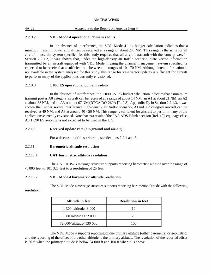
2.2.11.2 VDL Mode 4 barometric altitude resolution
The VDL Mode 4 message structure supports reporting barometric altitude with the followingresolution:
Altitude in feet Resolution in feet
-1 300<altitude<8 000 10
8 000<altitude<72 000 25
72 000<altitude<130 000 100
The VDL Mode 4 supports reporting of one primary altitude (either barometric or geometric)and the reporting of the offset of the other altitude to the primary altitude. The resolution of the reported offsetis 50 ft when the primary altitude is below 24 000 ft and 100 ft when it is above.

AMCP/8-WP/66
Appendix to the Report on Agenda Item 4 4A-23
2.2.11.3 1 090 ES barometric altitude resolution
The 1 090 ES ADS-B message structure supports reporting barometric altitude over the range-100 feet to 50 175 feet to a resolution of 25 feet. For altitudes above 50 175 feet, the resolution is 100 feet.
2.2.12 Geometric altitude resolution
2.2.12.1 UAT geometric altitude resolution
The UAT ADS-B message structure supports reporting geometric altitude over the range of-1 000 feet to 101 325 feet to a resolution of 25 feet. Additionally, UAT supports reporting of geometric altitudeas a “Secondary” altitude simultaneously (at a lower update rate) with barometric altitude.
2.2.12.2 VDL Mode 4 geometric altitude resolution
The VDL Mode 4 message structure supports reporting of geometric altitude resolution withthe same resolution as defined for the barometric altitude (see previous section).
2.2.12.3 1 090 ES geometric altitude resolution
When barometric altitude is the primary altitude being reported, geometric altitude is reportedas GNSS Height Above the Ellipsoid, with a resolution dependent upon altitude, which is the same as thatdescribed in Section 2.2.11.3.
2.2.13 RF frequency
2.2.13.1 UAT RF frequency
Because of the safety aspects of surveillance operations, some national policies require thatsurveillance operations occur in frequency bands that are protected for aeronautical radionavigation service(ARNS). The UAT is being approved for operation in the United States at 978 MHz, part of the960 - 1 215 MHz ARNS band. Since the UAT is proposed for international operation at 978 MHz, the UAToperating frequency is suitably protected to support critical surveillance applications. Suitability for UAT tooperate in the 960 - 1 215 MHz band under existing allocations is being reviewed in certain States.
The 978 MHz frequency is currently allocated to DME and TACAN. In part, because radioregulations define use of 978 MHz for DME/TACAN for emergency use, only seven operational DME/TACANstations have been identified worldwide as operating on 978 MHz. All seven of these stations are in the ICAOEuropean region.
Operational impact on the use of UAT on the surface of a co-located 979 MHz (1 MHz offset)DME/TACAN ground station remains under review.

AMCP/8-WP/66
4A-24 Appendix to the Report on Agenda Item 4
2.2.13.2 VDL Mode 4 RF frequency
VDL Mode 4 SARPs specify operation in the VHF AM(R)S band. In addition the operationin the VHF ARNS band is recommended. In order for the latter to be enabled the relevant discussions in ITUshould conclude favorably.
Frequencies for VDL Mode 4 in Europe have been proposed by Eurocontrol. The plananticipates placing the VDL Mode 4 frequencies at the top of the VHF AM(R)S band and has been approvedby the ICAO EUR Frequency Management Group (FMG) in Europe.
It is uncertain at this time whether VDL Mode 4 will be permitted to use frequencies in theVHF ARNS band. The proposal to the FMG included two frequencies in the upper VHF AM(R)S band and twofrequencies in the VHF ARNS band. The European planning activity is proposing four channels for VDLMode 4 use.
For the performance analysis in the high-density air traffic scenario presented in this study, withtransmission rates as set by the VDL Mode 4 experts participating in this analysis, four channels were requiredfor air-to-air state vector transmissions alone. A realistic single-link VDL Mode 4 ADS-B system for thisscenario would require 3 - 4 additional channels to support ADS-B surface operations, higher ADS-B broadcastrates for aircraft on approach, and long range air-to-air and air-to-ground deconfliction applications. Thisanalysis assumed eight VDL Mode 4 receivers cards per aircraft (four per antenna).
2.2.13.3 1 090 ES RF frequency
The 1 090 MHz frequency has been approved for 1 090 ES operation on a global basis.Because of the safety aspects of surveillance operations, some national policies require that surveillanceoperations occur in frequency bands that are protected for aeronautical radionavigation service (ARNS).Operational impacts on radar systems of the transmission of extended squitters on the surface and outside ofthe movement areas of airports remain under review.
2.2.14 Antenna requirements
2.2.14.1 UAT antenna requirements
Depending on the UAT equipment class of the installation, UAT will require either one or twoantennas. The type of antennas currently in use on civil aircraft for either DME or transponder operation willperform well for UAT. Furthermore, testing of two separate commercially available diplexer devices isunderway at FAA Technical Center. It is expected that these diplexer devices will allow sharing of the existingtransponder antenna(s) with UAT. This could be especially applicable for air-carrier installations where thetransponder antenna network includes top and bottom antennas and manages access to redundant transponders(ADS-B systems).
Additionally, one major equipment manufacturer has investigated an antenna sharingimplementation for a new transponder/UAT integrated implementation and has indicated that such animplementation is feasible.

AMCP/8-WP/66
Appendix to the Report on Agenda Item 4 4A-25
2.2.14.2 VDL Mode 4 antenna requirements
The VDL Mode 4 system is expected to be implemented using one or two antennas. A singleantenna installation is typical for a ground vehicles, gliders, small general aviation etc. A two-antenna installationis typical for general aviation and air transport. A two-antenna configuration could use both antennas forreceiving and one or both for transmitting. It may be possible to share antennas with other VHF systems, butthis needs to be analysed in specifying an overall airborne architecture.
For the performance analysis in the high-density air traffic scenario presented in this study, itwas assumed that all aircraft were equipped with two antennas, one on top and one on the bottom, and that bothwere used for receiving and that transmissions alternated between the two.
2.2.14.3 1 090 ES antenna requirements
Antenna requirements for 1 090 ES on air transport class aircraft will generally be met byexisting transponder/TCAS antennas. Antenna guidance for general aviation aircraft is provided in RTCAMOPS. The 1 090 ES antenna requirements are provided in Section 2.2.13 of RTCA DO-260A [Ref. 8], andthe antenna characteristics are defined in Appendix C of RTCA DO-260A.
2.2.15 Spectrum efficiency
2.2.15.1 UAT spectrum efficiency
The ICAO 960 - 1 215 MHz channel plan divides the band into distinct 1 MHz paired channels(i.e. 1 MHz for the uplink signal and 1 MHz for the downlink signal). Due to its use of spectrally efficientfrequency shift keying (FSK) modulation, the UAT requires a single 1 MHz channel to meet combineduplink/downlink ADS-B and TIS-B requirements even in the most stringent and challenging ATC environments.In addition, that single channel will also provide 32 assignable “sub-channels” for uplink of broadcast messagessuch as FIS-B. Because of the format of the ICAO channel plan, utilization of the 978 MHz frequency (uplinkfor channel 17X) for UAT does not preclude the use of the paired 1 041 MHz (downlink for channel 17X)frequency, as that frequency is also used as part of the 17Y (1 041/1 104 MHz) pair.
2.2.15.2 VDL Mode 4 spectrum efficiency
The STDMA technique and multi-channel concept provide flexible alternatives forimplementing VDL Mode 4 with spectrum efficiency in mind. When an entire 25 kHz channel is used to itsmaximum capacity, a new channel can be allocated to cope with a more demanding air traffic scenario.
The VDL Mode 4 system spectrum efficiency in terms of bits per second per Hz of channelbandwidth also depends on the number of guard bands that may need to be used. The number of guardchannels required will be specified by compliance with VDL Mode 4 frequency planning criteria currently beingdeveloped by AMCP. Draft frequency planning criteria propose that adjacent channel interference to a VDLMode 4 channel be limited so as to degrade message success rate by no more than two percent. (This metricwould imply that the maximum message success rate for VDL Mode 4, independent of range, would need tobe less than 98%.)
Note that studies should be performed to determine if it is possible for additional uplinkbroadcast services, such as FIS-B and TIS-B to be accommodated in the guard bands located between the

AMCP/8-WP/66
4A-26 Appendix to the Report on Agenda Item 4
channels allocated for air/air and air-ground services. This would have the potential to enable efficient spectrumutilization.
2.2.15.3 1 090 ES spectrum efficiency
The 1 090 ES system shares already allocated aeronautical spectrum and in fact improves theutilization of that spectrum by providing additional services therein. The additional interference caused byADS-B transmissions on 1 090 MHz is not projected to produce a material impact on the operation of the SSRor ACAS systems.
2.2.16 Support to all classes of users
2.2.16.1 UAT support to all classes of users
UAT is expected to support the full range of users with no special installation constraints thatwould limit its adoption. RTCA DO-282 [Ref. 7] addresses a range of equipment classes to tailor UATequipment to the appropriate cost/performance combination for each class of potential user. In addition, asdescribed in Sections 1 and 15, UAT has been shown to be resistant to the numerous co-site transmissions on1 030 and 1 090 MHz, and tests are ongoing into the possibility of shared L-band antennas.
2.2.16.2 VDL Mode 4 support to all classes of users
VDL Mode 4 is expected to be available to all classes of users. The low power requirementssupport the low-end category of users (ground vehicles, gliders, etc). For example, recent airport surface testingat London Heathrow has confirmed advantages of using the VHF band referred to in section 2.2.30.2.
2.2.16.3 1 090 ES support to all classes of users
The 1 090 ES system has been designed to support the full spectrum of aviation users (seeSection 2.1.11 of RTCA DO-260A [Ref. 8]). Cost implications of the system for general aviation were a factorin the July, 2002 FAA ADS-B link decision [Ref. 10], which discusses the choice of UAT as the general aviationADS-B link within the U.S. National Airspace System.
2.2.17 Support of related applications
2.2.17.1 UAT support of related applications
UAT has specifically been designed to attempt to support, in both today’s and futurehigh-density airspaces, the air-to-air and air-ground ADS-B applications in industry ADS-B system-leveldocuments including the Minimum Aviation System Performance Standards for ADS-B developed by RTCASpecial Committee 186, the Free Flight Operational Enhancements proposed by the RTCA Free Flight SelectCommittee, and air-ground applications articulated by Eurocontrol during the Technical Link Assessment Teameffort. UAT complies with 225 of 228 RTCA DO-242A [Ref. 3] requirements and offers near-compliance withthe remaining three. UAT further fully meets one of three Eurocontrol additional criteria and partially meetsanother. Assessment of the UAT against the technical requirements mentioned above is provided in Sections 3and 4 of this paper as well as in Appendix A. UAT is intended to support other applications, such as thosediscussed in Appendix E of RTCA DO-242A.

AMCP/8-WP/66
Appendix to the Report on Agenda Item 4 4A-27
Additionally, the Ground Uplink Segment of UAT was designed expressly to supportsurveillance- and situational awareness-related broadcast services such as Traffic Information Service-Broadcast(TIS-B) and Flight Information Service-Broadcast (FIS-B). UAT has been assessed as supporting all mandatoryrequirements of the Minimum Aviation System Performance Standards for FIS-B published by RTCA in 2001.
2.2.17.2 VDL Mode 4 support of related applications
VDL Mode 4 offers the potential and flexibility to support multiple applications since it is achannelized system (different applications can be separated onto different channels), and is designed to supportcommunications, navigation and surveillance applications. For example the system supports both air-ground andair-air point to point communications services.
Even though VDL Mode 4 supports reception/transmission on different channels for differentservices this is not a necessity. In both high- and low-density airspace a well-planned, interconnected groundinfrastructure can optimize the channel usage.
2.2.17.3 1 090 ES support of related applications
The 1 090 ES system can directly support hybrid surveillance, a technique which uses thereceipt of ADS-B information to improve the spectrum efficiency of ACAS. Furthermore, 1 090 ES uses theoverall Mode S message frame structure, the most similar message format being Comm B; therefore, there isa synergy between Extended Squitter and Mode S Data Link equipage.
2.2.18 Minimal complexity
2.2.18.1 UAT minimal complexity
The TLAT agreed that the UAT has the simplest technical concept among the three links(TLAT report [Ref. 4] Section 5.1.2). The following attributes of UAT allow it to be implemented with aminimal amount of complexity:
C No tracking or message assembly required to generate ADS-B reports;
C No latitude/longitude decompression or ambiguity resolution is required;
C No channel sensing required for performing media access; and
C No channel management or tuning required
2.2.18.2 VDL Mode 4 minimal complexity
VDL4 has a simple control architecture for low density airspace regions. For high densityregions VDL4 has a moderate complexity control arch using ground protocols to manage the assignment ofchannels for bdcst services. This is handled by broadcasting Directory of Service messages in the GlobalSignaling Channels (GSCs).

AMCP/8-WP/66
4A-28 Appendix to the Report on Agenda Item 4
6 In particular ICAO Annex 10 notes, “108.0 MHz is not scheduled for assignment to ILS service. The associated DME operatingchannel No. 17X may be assigned for emergency use.”
2.2.18.3 1 090 ES minimal complexity
The 1 090 ES system has moderate to high complexity, because of properties of the legacysystems with which it must interoperate. On the other hand, this complexity is in most cases well understood,because of extensive operational experience with these legacy systems. The addition of a 1 090 ES capabilityto a Mode S transponder introduces modest additional complexity.
2.2.19 Non-interference with other aeronautical systems
2.2.19.1 UAT non-interference with other aeronautical systems
The UAT has been designed to operate at 978 MHz, in the lower portion of the960 - 1 215 MHz ARNS band. This band is extensively used throughout the world for DME and TACAN. Theband is also utilized in some States on a non-interference basis by the military JTIDS/MIDS. Recognizing thisheavy use, UAT has been specifically tailored - through matched hardware filters, and extensive digitalerror-correction coding - to be compatible with high-density pulsed environments. Coupled with the selectionof a UAT center frequency (978 MHz) that is unused for DME/TACAN in much of the world due to difficultiesprotecting its paired VHF omni-directional range (VOR) frequency from FM broadcast stations6 , testing/analysishas confirmed that the UAT can be introduced to the band with no change required to either DME/TACAN“ramp tester” utilization or JTIDS/MIDS operations. Furthermore, DME/TACAN testing has shown thatacceptable operational DME/TACAN performance will be maintained for co-channel (978 MHz) DME/TACANassignments even in the presence of high-density UAT environments, and that UAT performance is achievedin the presence of high-density co-channel DME/TACAN in low-density UAT self-interference environments.Note that while future UAT performance will ultimately require vacating some number of the 7 European978 MHz operational DME/TACAN assignments, the robust nature of the UAT signal, together with itsnon-interference to DME/TACAN applications, will greatly ease system transition in those limited geographicareas where 978 MHz is used for DME/TACAN.
Whilst a suitable frequency seems likely to be available in the USA, the European situation ismore complex. The ECAC navigation strategy foresees the long-term use of DMEs to support GNSS inproviding a harmonised area navigation environment. This will require significant deployment of new DMEsin Europe, in particular within terminal areas. The current estimate is that 180 - 200 new DMEs will be requiredby 2010. Assignment of UAT to 978 MHz in Europe will need to be coordinated with execution of this ECACnavigation strategy which itself will need to be reconciled with current radio regulations for the use of 978 MHzby DME/TACAN. The performance analysis for this study accounted for all currently planned DME/TACANallocations.
Additionally, the single-aircraft UAT duty cycle is .0004, which provides a low level of co-siteinterference to other systems.

AMCP/8-WP/66
Appendix to the Report on Agenda Item 4 4A-29
2.2.19.2 VDL Mode 4 non-interference with other aeronautical systems
VDL Mode 4 will operate in the VHF aeronautical band on dedicated channels. The frequencyplanning criteria should address the interference issue to systems (VDL Mode 4 and others) operating inadjacent channels. Section 2.2.1.2.1.3 states that the analysis done for this report allows for the accepted levelof adjacent channel interference. The analysis also assumes no other interference of any sort.
2.2.19.3 1 090 ES non-interference with other aeronautical systems
The “notching” of the 1 090 MHz frequency with regard to frequency allocation of servicesother than SSR and ACAS substantially mitigates any interference by 1 090 ES with the operation of such othersystems. The operation of 1 090 ES is not projected to materially affect the performance of the SSR and ACASsystems. With regard to co-site interference by 1 090 ES on other L-band aircraft systems, responses tointerrogations by SSR and TCAS take precedence over the transmission of 1 090 ES. The duty cycle of1 090 ES is at worst on the order of .001. This low duty cycle, in conjunction with standard mutual suppressiontechniques, implies that co-site interference of 1 090 ES should have no material operational impact.
2.2.20 Transition issues
All ADS-B link will require new aircraft equipment and ground infrastructure. The transitionprocess must take into account timescales for the introduction of ADS-B applications by air navigation serviceproviders and aircraft equipage. TIS-B is an important application to support the transition process.
2.2.20.1 UAT transition issues
The design of the UAT Ground Uplink Segment furnishes an alternative implementation oftransition services such as TIS-B that provides no interference to UAT transmissions from equipped aircraft,should such an alternative implementation become necessary in high-density airspace. The proposed UATfrequency of 978 MHz is, on a worldwide basis, populated by only 7 DME/TACAN assignments. Investigationof the use of a diplexer to permit the sharing of existing transponder antennas by UAT avionics is beingundertaken.
2.2.20.2 VDL Mode 4 transition issues
The protocol stack of VDL Mode 4 enables Ground-to-Air services (e.g. TIS-B) to betransmitted in either the pre-protected slots of the VDL Mode 4 timeframe or in protected slots assigneddynamically. It is also possible to transmit on dedicated channels.
2.2.20.3 1 090 ES transition issues
The 1 090 ES system has specific attributes that support transition to ADS-B in severalimportant ways. First, early operational implementation of ADS-B on a worldwide basis can be supported atpresent, because of the worldwide frequency allocation and SARPS for the 1 090 ES system. In large partbecause of this attribute, as well as the synergy between 1 090 ES and existing SSR/ACAS avionics, the1 090 ES system has been selected by the FAA and is under consideration by Eurocontrol as the near-termADS-B link for ADS-B implementation that is interoperable between the United States and Europe. The 1 090ES system also supports TIS-B.
AMCP/8-WP/66
4A-30 Appendix to the Report on Agenda Item 4
Both Boeing and Airbus are expected to deliver their new commercial air transport aircraft with1 090 ES installed beginning in 2003, using the initial 1 090 ES MOPS (DO-260 [Ref. 8]) as a baseline (see2.2.25.3 below). TCAS/ACAS manufacturers are either currently shipping or have plans to offer by 2003avionics that also incorporate 1 090 ES capability.
2.2.21 Impact of fundamental design: frequency band
2.2.21.1 UAT impact of fundamental design: frequency band
The ICAO 960 - 1 215 MHz channel plan divides the band into distinct 1 MHz paired channels(i.e. 1 MHz for the uplink signal and 1 MHz for the downlink signal). This supports designs like the UAT thatutilize high burst rate, unscheduled transmissions on a single channel. The choice of frequency band for UAThas beneficial cost impacts as discussed in Section 2.2.31.1. The UAT has been designed to operate compatiblywith existing users of the band, and from a regulatory standpoint, at least one Administration’s responsibleagency has made a preliminary ruling that UAT is an acceptable use of the band under the existing provisionsfor “electronic aids to airborne navigation” as contained in S5.328 of the International TelecommunicationsUnion (ITU) Radio Regulations.
2.2.21.2 VDL Mode 4 impact of fundamental design: frequency band
VDL Mode 4 operates in the VHF aeronautical band. As a result, it is a 25 KHz system andthe choice of this band provides long-range performance using low power transmissions, while necessitatingmulti-channel operation in high-density airspace.
The radio wave propagation characteristics in the VHF band make VDL Mode 4 well suitedto operation in all phases of flight, including operations on the ground. The recent trials at Heathrow haveindicated that good results are obtained with VDL Mode 4 for surface operations.
2.2.21.3 1 090 ES impact of fundamental design: frequency band
The frequency band in which 1 090 ES system operates provides wide channelization (8 MHzband allocation), which is well-suited to broadcast services.
2.2.22 Impact of fundamental design: modulation
2.2.22.1 UAT impact of fundamental design: modulation
The UAT uses continuous phase frequency shift keying modulation. The continuous phaseaspect limits the bandwidth of the transmitted signal, while frequency shift keying supports simple, cost-effectivereceiver and transmitter equipment, as no knowledge of the phase of the carrier (i.e. carrier coherence) isneeded.

AMCP/8-WP/66
Appendix to the Report on Agenda Item 4 4A-31
2.2.22.2 VDL Mode 4 impact of fundamental design: modulation
VDL Mode 4 uses a GFSK modulation scheme, which provides a 19.2 kbps data rate withina message, while providing a relatively low 12 dB D/U ratio for a system involving airborne transmitters(Manual on Detailed Technical Specifications for the VDL Mode 4 Digital Link [Ref. 11]). A required D/U of10 dB is specified in MOPS as a result of tests on equipment.
2.2.22.3 1 090 ES impact of fundamental design: modulation
The 1 090 ES system uses the well-understood and validated modulation scheme of theMode S data link (ICAO Annex 10, Volume IV [Ref. 12]).
2.2.23 Impact of fundamental design: multiple accesstechnique
2.2.23.1 UAT impact of fundamental design: multiple access technique
UAT operates in a single channel using the same frequency for transmit and receive. The UATframe is divided into two segments. One segment uses a random access protocol and is used for mobile stationtransmissions. The other segment is used for ground station transmissions and is divided into timeslots.
The impacts of the above multiple access techniques are:
C Ground uplink transmissions do not interfere with aircraft transmissions, and vice versa,improving the robustness of ADS-B and ground uplink services.
C UAT spectrum efficiency is improved and equipment design is simplified.
2.2.23.2 VDL Mode 4 impact of fundamental design: multiple access technique
VDL Mode 4 system utilises a self-organising TDMA access scheme, which provides forautonomous and ground controlled modes.
2.2.23.3 1 090 ES impact of fundamental design: multiple access technique
1 090 ES uses a randomized media access protocol, with dithering of successive transmissionsfrom a single ADS-B system participant.
2.2.24 Maturity of technology
2.2.24.1 UAT maturity of technology
UAT technology has been used operationally for 170 aircraft to supply radar-like ATC servicesand improved situational awareness in the FAA Alaska region. This operational experience has served as thebasis for the recent completion of MOPS, U.S. spectrum approval for use of the system at 978 MHz, anddevelopment of a Technical Standard Order (TSO) C-154, which is the first certification order for operationalADS-B equipment. Two hundred additional aircraft will be equipped with MOPS-compliant, certified UATequipment by 2004, and existing operational UAT equipment will be upgraded to the certification baseline

AMCP/8-WP/66
4A-32 Appendix to the Report on Agenda Item 4
provided by the MOPS and TSO. UAT is sufficiently mature that SARPS development has started on an at-riskbasis.
2.2.24.2 VDL Mode 4 maturity of technology
VDL Mode 4 has ICAO provisions approved. In addition interim MOPS (ED-108) have beendeveloped and are being updated. A European Norm (EN) for ground stations has been developed (EN 301842parts 1 and 2, December 2002).
A local implementation of STDMA/VDL Mode 4 for surface movement applications has beenin operation since 1988 at Arlanda Airport tracking ground vehicles for snow clearance operations.
An ADS-B ground station has been installed at Kiruna, in northern Sweden which does nothave radar. The VDL Mode 4 ground station is intended to support ATC surveillance through the presentationof equipped aircraft on a situation display in the control tower. At Arlanda Airport, VDL Mode 4 will serve asa common platform for distribution of operational data. When fully implemented the system will provide ADS-Breporting for a large number of airport surface vehicles and a number of SAS and other operators’ aircraft.
Trials and flights have taken place in various projects in Europe and details are provided inSection 2.2.25.2.
2.2.24.3 1 090 ES maturity of technology
The 1 090 ES system builds upon mature SSR technology. Joint RTCA-EUROCAE MOPSand ICAO SARPS and guidance material are available and are being updated to reflect the improved 1 090 ESdesign under assessment in this document.
2.2.25 2.2.25 ADS-B related activities and time-scales
2.2.25.1 UAT ADS-B related activities and time-scales
UAT (in a pre MOPS form) has been used in the FAA’s Alaska Capstone programmebeginning in February 2000. UAT is currently installed on over 170 air taxi aircraft in Western Alaska. Beginningin January 2001, the UAT/ADS-B has been supporting the first operational use of ADS-B for aircraft in flight,providing ATC radar-like services in the Bethel Alaska area. The Capstone programme plans to replace thepre-MOPS UATs with MOPS compliant equipment and add approximately 200 aircraft in Southeast Alaskabeginning in 2003.
2.2.25.2 VDL Mode 4 related activities and time-scales
A number of trials involving VDL Mode 4 have been completed or are underway.Demonstrations of VDL Mode 4 support for air-air, air-ground and surface surveillance have been conductedin Europe including North-European ADS-B Network (NEAN), NEAN Update Programmeme (NUP),Mediterranean Free Flight (MFF) and Mediterranean Update Programmeme (MEDUP). NEAN provided earlyevidence that ADS-B is feasible and can be used in ATM from gate-to-gate. Based on the experiences fromNEAN and associated projects, the NUP was formed to move the work closer to operational use byinvestigating the necessary steps in terms of certification, aircraft integration and application development. NUPis entering its second phase with the objective of establishing a European ADS-B network based on global

AMCP/8-WP/66
Appendix to the Report on Agenda Item 4 4A-33
standards supporting certified applications and equipment in synergy with the European ATM conceptsproviding benefits to ATM stakeholders.
Within Sweden, the network implemented as part of the NEAN programmeme is being updatedto become fully compliant with the ICAO VDL Mode 4 provisions within the framework of NUP. The networkof ground stations will be made denser by a national programmeme called ADS2005.
The MEDUP and MFF programmes are evaluating the feasibility of applying ADS-B servicesin the Mediterranean area. MEDUP is focused on establishing an extensive VDL Mode 4 infrastructure, whileMFF is focused on operational aspects while taking advantage of ADS-B based services. Live flight trials areplanned.
2.2.25.3 1 090 ES related activities and time-scales
Existing RTCA and ICAO standards for 1 090 ES are being updated. The updated RTCAMOPS are expected to be published in the second quarter of 2003 and the FAA will then publish a TSO somemonths later. This TSO will be used as the basis for the certification of 1 090 ES for operational use in theUnited States. Corresponding revisions to the ICAO standards are expected to be approved at SCRSP/1 in 2004.The revisions to the 1 090 ES standards maintain backward compatibility with the existing RTCA, EUROCAEand ICAO standards. Version 0 (DO-260 conformant) is currently being installed in some aircraft. 1 090 ES(version 0) systems have been installed on aircraft to support broadcast-only (i.e. air-to-ground applications)trials in Australia.
2.2.26 Interoperability
Note that all ADS-B links evaluated support TIS-B, thereby assisting interoperability withnon-equipped aircraft.
2.2.26.1 UAT interoperability
The UAT MOPS, updated as needed to ensure conformance with anticipated UAT SARPS,will continue to ensure interoperability across different vendor implementations of UAT.
As articulated in the 2002 FAA ADS-B Link Decision Document [Ref. 10], interoperabilitybetween UAT and the 1 090 ES in the United States will be supplied through ADS-B gateways. Moreover,multi-link implementations within a single aircraft are being explored (e.g. see the discussion inParagraph 2.2.14.1 above).
2.2.26.2 VDL Mode 4 interoperability
The VDL Mode 4 SARPS, MOPS (when approved), and EN will ensure interoperabilitybetween systems developed by different manufacturers.

AMCP/8-WP/66
4A-34 Appendix to the Report on Agenda Item 4
2.2.26.3 1 090 ES interoperability
The 1 090 ES SARPS and MOPS will ensure interoperability across different vendorimplementations of 1 090 ES.
As articulated in the 2002 FAA ADS-B Link Decision Document [Ref. 10], interoperabilitybetween UAT and 1 090 ES in the United States will be supplied through ADS-B gateways. Moreover,multi-link implementations within a single aircraft are being explored.
2.2.27 Flexibility
2.2.27.1 UAT flexibility
UAT offers flexibility in the following areas:
C Future changes to the ADS-B message structure could be accommodated through over 20spare payload type codes that are unused in the current MOPS definition of the system.
C The 5 UAT equipment classes defined in RTCA DO-282 [Ref. 7] allow users theflexibility to install a system with only the cost and performance that meets their needs.
C Due to the frequency relationship between UAT and the 1 030/1 090 MHz SSR system,use of a diplexer device to share antennas with the transponder will offer some flexibilityfor installation on aircraft.
2.2.27.2 VDL Mode 4 flexibility
The VDL Mode 4 provides the flexibility to define new messages following the evolution ofthe application requirements. The high degree of configurability of VDL Mode 4 permits it to be highlyadaptable to changes in airspace needs and composition.
VDL Mode 4 has the flexibility to support other services such as ground broadcast andpoint-to-point communications, either air-to-ground or air-to-air. Air-to-air communications may be arequirement for advanced airborne separation assistance system (ASAS) applications.
It is possible to take advantage of the position data provided by VDL Mode 4 to enhance thesafety and security of data communication and to manage the communication system for maximum channelutilization. The use of position data is an inherent advantage of a system supporting combined CNS services.
2.2.27.3 1 090 ES flexibility
1 090 ES has necessarily been designed with a number of constraints owing to its relationshipwith SSR/ACAS. These same relationships support cost-effective flexibility in partitioning surveillanceimplementation between SSR, ACAS, and ADS-B as a function of time. Multiple equipage classes of 1 090 ESavionics have been defined to provide users with a choice of functionality and cost.

AMCP/8-WP/66
Appendix to the Report on Agenda Item 4 4A-35
2.2.28 Non-proprietary
ICAO policy is that if there is any need to use a patent then the patent must be offered forlicense to aviation in a fair, reasonable and non-discriminatory way.
2.2.28.1 UAT non-proprietary
The UAT system does not have any known proprietary aspects.
2.2.28.2 VDL Mode 4 non-proprietary
AMCP/7 noted that no patents applicable to the VDL Mode 4 SARPs were identified at themeeting. It therefore concluded that the material proposed in the SARPs would be freely accessible toeverybody, subject to no particular conditions.
2.2.28.3 1 090 ES non-proprietary
The holder of a key patent for 1 090 ES technology has made that technology available to theaviation community without any financial obligation. Therefore, there are no known proprietary issuesassociated with 1 090 ES.
2.2.29 Robustness/fallback states
2.2.29.1 UAT robustness/fallback states
Under normal conditions UAT relies on timing information derived from GNSS. Timinginformation from GNSS is needed primarily to support a range to target measurement independent of ADS-B.Upon a failure of GNSS, the navigation input to UAT could come from any appropriate navigation source(e.g. inertial, FMS). For timing the UAT can fall back to timing derived from receipt of uplink messages fromground stations in order to prevent ADS-B transmissions from conflicting with ground uplink transmissions. Inthis fallback condition, the independent range measurement would not be available, but basic UAT ADS-Btransmission performance should not be affected.
2.2.29.2 VDL Mode 4 robustness/fallback states
VDL Mode 4 provides 3 timing modes. The primary timing Mode relies on GNSS to providethe required accuracy. The two fallback modes support continuing operations. If a station is unable to maintainprimary time, a station reverts to secondary timing. Under secondary timing, the station uses its internaloscillator to limit the drift away from UTC. Under tertiary timing, no sources synchronized to UTC are availableand stations transmit a time calculated as the mean slot start time of the surrounding transmitters. Thiscircumstance, while degrading VDL Mode 4 communications, will not result in a loss in communicationcapability, the drift away from UTC will result in errors when the stations are resynchronized to UTC.

AMCP/8-WP/66
4A-36 Appendix to the Report on Agenda Item 4
2.2.29.3 1 090 ES robustness/fallback states
The randomized nature of 1 090 ES media access mitigates the impact of avionics failure of any given ADS-Bsystem participant. Additionally, operation of the 1 090 ES system does not substantively degrade when precisetiming (e.g. from GNSS) is lost. The enhanced Extended Squitter decoder provides for improved probabilityof successful receipt of an ADS-B Extended Squitter in the presence of multiple SSR overlaps.
2.2.30 Future suitability
2.2.30.1 UAT future suitability
UAT has been demonstrated, through simulation and analysis, to be suitable to support mostair-to-air ranges and ADS-B Report update requirements, required and desired, of RTCA DO-242A in“worst-case” future (2015) high-density airspaces. Line-of-sight reception for air-ground applications has beenensured as well, using a single ground station (although multiple sector ground antennas may be required in areasof significant off-channel DME activity).
2.2.30.2 VDL Mode 4 future suitability
VDL Mode 4 offers a flexible solution in that it provides variable reporting rates and is able toprovide other services such as ATN communications. It can also provide air-to-air point-to-pointcommunications. It is expected to offer good airport surface performance as VHF has good ground propagationcharacteristics.
2.2.30.3 1 090 ES future suitability
The 1 090 ES system is projected to be suitable for high update rate, short range air-air andair-ground ADS-B applications (e.g. hybrid surveillance, support of parallel runway approaches, enhancedsee-and-avoid, conflict detection, air-ground applications within a TMA) for the foreseeable future.
2.2.31 Cost
Only two known attempts to comprehensively assess costs of the three ADS-B link have beenundertaken. The FAA undertook a comprehensive cost analysis in 2001 - 2002 as part of its ADS-B linkdecision process. (see http://adsb.tc.faa.gov/ADS-B.htm) which showed UAT to have relatively lower costprofiles across all classes of installations. Note that this was a snapshot of the market and it is expected thatcosts for all links may change in the future. Similar considerations have been taken by Eurocontrol and theEuropean Commission [www.datalinkroadmap.com], concluding that costs were scenario dependent and thatthe cost of link avionics was not a discriminator among the links. Equipment cost considerations can indeed becomplex, and proponents of individual ADS-B links have objected, for one reason or another, to assumptionsmade in the cost analyses referred to above.

AMCP/8-WP/66
Appendix to the Report on Agenda Item 4 4A-37
2.2.31.1 UAT cost
The following factors of the UAT design serve to minimize its installed system cost:
C The frequency of UAT operation and its very low duty cycle, may make it practical toshare antenna with transponder systems. This could be an important consideration on airtransport category aircraft where the transponder antenna network supports both diversityand access from redundant transponder units.
C The single channel operation of UAT eliminates the need for multiple channels or logic tosupport channel tuning.
C A random-based media access allows for minimal transmit-only installations and requiresonly simple logic
As an example of costs for small single engine aircraft, the FAA’s Alaska Capstone programme has purchasedapproximately 180 shipsets of avionics equipment at a cost of around $20 000 per shipset installed. This costincludes UAT avionics, a GPS navigator, a multifunction cockpit display, and installation (average of $5 000).The breakdown of cost between UAT avionics, GPS navigator, and the multifunction cockpit display is notpublicly available. Installed equipment cost for large air transport aircraft will be higher.2.2.31.2 VDL Mode 4 cost
VDL Mode 4 is designed to be applicable to all classes of users (including for example groundvehicles). For low-end users it should be possible to provide low-cost installations based around a simplearchitecture of a single box containing VHF data link and GPS receiver equipment.
2.2.31.3 1 090 ES cost
In the FAA Safe Flight 21 Pre-Investment Analysis (July, 2002), costs of installing 1 090 ESADS-B equipment on a number of different categories of aircraft were calculated. In developing the avionicscosts, the team worked with avionics manufacturers to come up with estimates for equipage costs. From theperspective of the unit point estimates of equipment cost, it was concluded that for air transport categoryaircraft, 1 090 ES offered attractive cost profiles over a range of aircraft types. The costs for low- and mid-endgeneral aviation equipage were estimated to be in the moderately high range.
3. RTCA ADS-B MASPS (DO-242A) COMPLIANCE
This section discusses ADS-B data link system performance as compared to the subset ofrequirements of RTCA DO-242A [Ref. 3] analogous to the earlier RTCA DO-242 requirements expresslyconsidered by the TLAT [Ref. 4]. Section 3.1 is a summary of the requirements and references to the sectionsof RTCA DO-282 [Ref. 7], VDL SARPS in Annex 10, Volume III [Ref. 13] and the Manual on DetailedTechnical Specifications for the VDL Mode 4 Digital Link [Ref. 11], and RTCA DO-260A [Ref. 8], whichdiscuss the results of analysis of the system performance and compliance with the criteria set forth in RTCADO-242A. Section 3.2 - 3.4 present summary discussions of compliance of the UAT, VDL Mode 4, and1 090 ES systems with the requirements of RTCA DO-242A selected for assessment.
AMCP/8-WP/66
4A-38 Appendix to the Report on Agenda Item 4
When assessing the needs of Free Flight Operational Enhancements as articulated by the RTCAFree Flight Select Committee and developed by the Safe Flight 21 Programme in the United States, the TLATconcluded that a DO-242 compliant ADS-B System would support those Operational Enhancements.
The VDL Mode 4 system configuration used in making this assessment is that used by theTLAT for the Core Europe 2015 scenario. The UAT and 1 090 MHz Extended Squitter configurations havebeen updated to be specifically aligned to the requirements of DO-242A (i.e. in terms of ADS-B informationfields broadcast), and therefore are including the broadcast of a small number of data fields not broadcast in theVDL Mode 4 configuration. The total payload impact on UAT, for example, of these additional fields is theaddition of 6 percent to the payload used in the TLAT analysis.
3.1 DO-242A ADS-B requirements and references
Table B-1: ADS-B MASPS compliance matrix
DO-242A ADS-B MASPS Requirements Compliance
RTCADO-242A[Ref. 3]Ref. #
(Section #)
Requirement Text
UAT (RTCA DO-282
[Ref. 7] Section #)
VDL Mode 41 090 ES (RTCADO-260A [Ref. 8]
Section #)
R2.3(§2.1.2)
The ADS-B system shall be capable oftransmitting messages containing theinformation specified in the followingsubsections [of §2.1.2].
N/A (see following) N/A (see following) N/A (see following)

AMCP/8-WP/66
Appendix to the Report on Agenda Item 4 4A-39
DO-242A ADS-B MASPS Requirements Compliance
RTCADO-242A[Ref. 3]Ref. #
(Section #)
Requirement Text
UAT (RTCA DO-282
[Ref. 7] Section #)
VDL Mode 41 090 ES (RTCADO-260A [Ref. 8]
Section #)
R2.5(§2.1.2.2)
The basic identification information to beconveyed by ADS-B shall include thefollowing elements:1. Call Sign (§2.1.2.2.1)2. Participant Address (§2.1.2.2.2.1) and
Address Qualifier (§2.1.2.2.2.2)3. ADS-B Emitter Category (§2.1.2.2.3)
CompliesTable 2-39
§2.2.4.5.4.2§2.2.4.5.1
§2.2.4.5.1.3.1§2.2.4.5.1.2
§2.2.4.5.4.1
Compliant ( see Note 1)
Call sign:Table 3-2Table 3-9Table 3-8aTable 3-11
Participant addressand Address Qualifier:
§1.3.2Table 1-5§1.3.2.2§1.4.2.2
Table 1-55ADS-B Emitter
Category:§3.3
Table 3-15‘small’ aircraft and‘large’ aircraft are
grouped together as‘medium aircraft’ in
VDL4Not covered are:
‘High vortex large’‘Cluster obstacle’
‘Line obstacle’
Complies§2.2.8.2.6
§2.2.5.1.11§2.2.5.1.1
§2.2.5.1.1.3
§2.2.8.2.3
§2.2.3.2.5.2
§2.2.8.2.7
R2.14(§2.1.2.4)
Position Information shall be transmitted in aform that can be translated, without loss ofaccuracy and integrity, to latitude, longitude,geometric height and barometric pressurealtitude.
Complies§2.2.4.5.2Table 2-11
§2.2.4.5.2.1§2.2.4.5.2.2
§2.2.4.5.2.3
Compliant§1.5.2.2
§3.3
Complies§2.2.3.2.3
§2.2.3.2.3.4.3
§2.2.3.2.3.7
§2.2.3.2.3.8
§2.2.3.2.4§2.2.3.2.4.7
§2.2.3.2.4.8
R2.19(§2.1.2.6)
Both barometric pressure altitude andgeometric height shall be reported, if availableto the transmitting ADS-B subsystem.
Complies §2.2.4.5.2.2
Table 2-13
Compliant§1.5.2.2
Table 1 - 68§3.3
Table 3-12Table 3-21
The Altitude Subfieldonly allows for a singlealtitude to be reported
as indicated by theAirborne PositionMessage “Type”
code.§2.2.3.2.4.3
AMCP/8-WP/66
4A-40 Appendix to the Report on Agenda Item 4
DO-242A ADS-B MASPS Requirements Compliance
RTCADO-242A[Ref. 3]Ref. #
(Section #)
Requirement Text
UAT (RTCA DO-282
[Ref. 7] Section #)
VDL Mode 41 090 ES (RTCADO-260A [Ref. 8]
Section #)
R2.30(§2.1.2.12)
Table 2-2 defines the navigation integritycategories [NIC] that transmitting ADS-Bparticipants shall use to describe the integritycontainment radius.
CompliesTable 2-15
compliant (note 1)VDL4 TM does not
support the NICparameter(s). Itdefines NUCP,
Table 1-67
Complies§2.2.3.2.7.2.6
Table 2.2.3.2.7.2.6
R2.31(§2.1.2.13)
Table 2-3 defines the navigation accuracycategories that shall be used to describe theaccuracy of positional information in ADS-Bmessages from transmitting ADS-Bparticipants.
Complies§2.2.4.5.4.9
Table 2-45
compliant (note 1)VDL4 TM does not
support the NACparameter(s).
It defines NUCP,Table 1-67
Complies§2.2.3.2.7.2.7
Table 2.2.3.2.7.2.7
R2.32(§2.1.2.13)
The NACP value broadcast from an ADS-Bparticipant shall include any inaccuracies in thereported position due to the transmittingparticipant's not correcting the position from thenavigation sensor to that of the ADS-B positionreference point (see §2.1.2.5).
Complies§2.2.4.5.4.9
Table 2-45
compliant (note 1)VDL4 TM does not
support the NACparameter(s).
It defines NUCP,Table 1-67
Responsibility forNACP adjustment lies
outside the1 090 MHz ES
equipment.Compliance must beassessed as part of
installationcertification.
§2.2.3.2.7.2.7Table 2.2.3.2.7.2.7
R2.33(§2.1.2.14)
[In determining NACV, the] velocity accuracycategory of the least accurate velocitycomponent being supplied by the reportingA/V's source of velocity data shall be asindicated in Table 2-4.
Complies§2.2.4.5.4.10
compliant (note 1)VDL4 TM does not
support the NACparameter(s). Itdefines NUCP,
Table 1-67
CompliesTable 2-20
Table 2-21
Table 2-22
R2.34(§2.1.2.15)
The Surveillance Integrity Limit encoding shallbe as indicated in Table 2-5
Complies§2.2.4.5.4.6Table 2-44
compliant (note 1)VDL4 TM does not
support the SILparameter
Complies§2.2.3.2.7.1.3.13
Table 2.2.3.2.7.1.3.13§2.2.3.2.7.2.9
R2.35(§2.1.2.16)
The Barometric Altitude Quality Code (BAQ),is a 2-bit field which shall be zero forequipment that conforms to version DO-242Aof the ADS-B MASPS
Complies§2.2.4.5.4.8
compliant (note 1)VDL4 TM does not
support the BAQparameter.
Complies§2.2.3.2.7.2.8

AMCP/8-WP/66
Appendix to the Report on Agenda Item 4 4A-41
DO-242A ADS-B MASPS Requirements Compliance
RTCADO-242A[Ref. 3]Ref. #
(Section #)
Requirement Text
UAT (RTCA DO-282
[Ref. 7] Section #)
VDL Mode 41 090 ES (RTCADO-260A [Ref. 8]
Section #)
R2.37(§2.1.2.19.1)
For equipage classes A2 and A3, the ADS-Bsystem shall provide the capability to transmitand receive messages in support of the TSreport. [TS report capability is optional forequipage class A1.]
Complies§2.2.4.5.6
§2.2.4.5.7
compliant (note 1)VDL4 TM definesSingle-slot TCP and
two-slot TCP in §3.3,Tables 3-8a, 3-9
CompliesTable 2-3Table 2-5
R2.38(§2.1.2.19.2)
For equipage class A2, the ADS-B systemshall provide the capability to transmit andreceive messages in support of one TC (TC+0)report.
Complies§2.2.4.5.8
Appendix L
compliantVDL4 TM definesSingle-slot TCP and
two-slot TCP in §3.3,Tables 3-8a, 3-9
It was assumed in theassessment that TCinformation was sent
on a separatechannel(s).
CompliesTable 2-3
Table 2-5
§2.2.3.2.7.1
R2.39(§2.1.2.19.2)
For equipage class A3, the ADS-B systemshall provide the capability to transmit andreceive messages in support of multiple TCreports.
Complies§2.2.4.5.8
Appendix L
compliantVDL4 TM definesSingle-slot TCP and
two-slot TCP in §3.3,Tables 3-8a, 3-9
It was assumed in theassessment that TCinformation was sent
on a separatechannel(s).
CompliesTable 2-3
Table 2-5
§2.2.3.2.7.7Appendix O
R3.1(§3.3.1)
ADS-B equipage classes summarized inTable 3-1 shall provide air-to-air coveragespecified in Table 3-2(a). The stated ranges arethe basis for the indicated relative effectiveradiated power (ERP) and the receiversensitivity requirement for each transmit unit.
Table 3-2 (a)
Class Range TX ERP RXsensitivityA0 10 NM $-2.5 dB +3.5 dBA1 20 NM 0 dB 0 dBA2 40 NM +3 dB -3 dBA3 90 NM #+6 dB -7 dBA3+ 120 NM #+6 dB -9.5 dB
Note — Required range requirements for A3and A3+ are forward direction coverage.Port and starboard coverage may be onehalf of this value; aft coverage may be onethird of this value.
Complies§2.1.11
Appendix F
Complies§2.1.12
Appendix F
Complies§2.1.13
Appendix F
Complies§3.1.1.2
Appendix F
compliant (note 2)
CompliesAppendix E
Table E-1Appendix P

AMCP/8-WP/66
4A-42 Appendix to the Report on Agenda Item 4
DO-242A ADS-B MASPS Requirements Compliance
RTCADO-242A[Ref. 3]Ref. #
(Section #)
Requirement Text
UAT (RTCA DO-282
[Ref. 7] Section #)
VDL Mode 41 090 ES (RTCADO-260A [Ref. 8]
Section #)
R3.2(§3.3.1)
The effective radiated power (ERP) andminimum signal detection capabilities shallsupport the associated pair-wise minimumoperational ranges listed in Table 3-2(b).
Table 3-2(b), Interoperability Ranges
RX A0 RX A1 RX A2 RX A3 RX A3+
TX A0: 10 NM 15 NM 21 NM 34 NM 45 NMTX A1: 13 NM 20 NM 28 NM 45 NM 60 NMTX A2: 18 NM 28 NM 40 NM 64 NM 85 NMTX A3: 26 NM 40 NM 56 NM 90 NM 120 NM
Complies§2.1.12
Table 2-2
§2.1.13
Appendix F
compliant (note 2)
CompliesFor performance in
high-density airspace,see Appendix P.Future possible
improvements forextended range
reception techniquesare discussed in
Appendix M.§2.2.2.1.1§2.2.4.1
§2.2.4.2§2.2.4.3
Appendix EAppendix I
Appendix P
R3.4(§3.3.1)
Ground vehicles operating on the airportsurface (class B2) shall provide a 5 NMcoverage range for Class A receivers.
In asurface-to-surface
multi-pathenvironment,
coverage range forground vehicletransmissions is
approximately 3 miles.§2.1.11
Table 2-1
This was not evaluated for this
report.See also 2.2.21.2
This was not evaluated for this
report.§2.2.2.2.10.2Appendix E

AMCP/8-WP/66
Appendix to the Report on Agenda Item 4 4A-43
DO-242A ADS-B MASPS Requirements Compliance
RTCADO-242A[Ref. 3]Ref. #
(Section #)
Requirement Text
UAT (RTCA DO-282
[Ref. 7] Section #)
VDL Mode 41 090 ES (RTCADO-260A [Ref. 8]
Section #)
R3.7(§3.3.2)
Each equipage class shall meet the requiredinformation broadcast and receiving capabilityat the indicated range to support theapplications indicated in Table 3-3(a) andTable 3-3(b).
Complies.§2.1.11
Table 2-1
Compliant (note 1, 2)
Complies.For performance in
high-density airspace,see Section 2.2.1.3.1
of this report. Future possible
improvements forextended range
reception techniquesare discussed in
Appendix M.§2.2.2.1§2.2.2.2§2.2.3
§2.2.4.2§2.2.4.3
Appendix EAppendix P
R3.8(§3.3.3.1)
… report acquisition shall be consideredaccomplished when all report elements requiredfor an operational scenario have been receivedby an ADS-B participant.
Complies§2.2.9
§2.2.9.1
Compliant. Complies§2.2.10.3
R3.9(§3.3.1.1)
Report accuracy, update period and acquisitionrange requirements are derived from thesample scenarios of Chapter 2, and arespecified in Table 3-3(a). The state vectorreport shall meet the update period and 99percentile update period requirements for eachapplication listed.
Compliant for all SVupdate applications atrequired and desired
ranges with oneexception: the
surface-to-surface 1.5second (95%) update
requirement.§2.2.8.2.2
§2.2.8.2.4(a)
Compliantfor applications with
desired ranges >10nmand < 70nm underloaded conditions.
See Section 2.2.1.2.1of this report.
Complies at rangesunder 40-50 NM
under loadedconditions.
For performance inhigh-density airspace,see Section 2.2.1.3.1
of this report.Appendix E Table E-1
Appendix P

AMCP/8-WP/66
4A-44 Appendix to the Report on Agenda Item 4
DO-242A ADS-B MASPS Requirements Compliance
RTCADO-242A[Ref. 3]Ref. #
(Section #)
Requirement Text
UAT (RTCA DO-282
[Ref. 7] Section #)
VDL Mode 41 090 ES (RTCADO-260A [Ref. 8]
Section #)
R3.10(§3.3.1.1)
For each of the scenarios included inTable 3-4(a), the state vector from at least95% of the observable user population (radioline-of-sight) supporting that application shallbe acquired and achieve the time andprobability requirements specified for theoperational ranges.
Complies at allrequired and desired
ranges, with exceptionnoted in R3.9.
§2.2.10.3
Table 2-67
Compliantfor applications with
desired ranges >10nmand < 70nm underloaded conditions.
See Section 2.2.1.2.1of this report.
Complies at rangesunder 40 - 50 NM
under loadedconditions.
For performance inhigh-density airspace,
see Appendix P.Future possible
improvements forextended range
reception techniquesare discussed in
Appendix M.Appendix EAppendix LAppendix P
R3.11(§3.3.3.1.1)
Required ranges for acquisition shall be asspecified in Table 3-4(a): (10 NM for A0,20 NM for A1, 40 NM for A2, and 90 NM forA3).
Complies§2.2.10.3
Table 2-67
This was notevaluated for this
report.
This was notevaluated for this
report. Forperformance in
high-density airspace,see Appendix P. Future possible
improvements forextended range
reception techniquesare discussed in
Appendix M.Appendix EAppendix LAppendix P
R3.14AR3.14B
(§3.3.3.1.2)
For each of the equipage classes included inTable 3-4(a), the Mode status reports from atleast 95% of the observable (radio line-of-sight)population shall be acquired at the rangespecified in the “Required 95th PercentileAcquisition Range” row of Table 3-4(b).(10 NM for A0, 20 NM for A1, 40 NM for A2,and 90 NM for A3). Likewise, for each of theequipage classes included in Table 3-4(b), theMode status reports from at least 99% of theobservable (radio line of sight) population shallbe acquired at the reduced range specified inthe “Required 99th Percentile AcquisitionRange” row of Table 3-4(b)
Complies§2.2.10.3
Table 2-67
This was notevaluated for this
report.
This was notevaluated for this
report.

AMCP/8-WP/66
Appendix to the Report on Agenda Item 4 4A-45
DO-242A ADS-B MASPS Requirements Compliance
RTCADO-242A[Ref. 3]Ref. #
(Section #)
Requirement Text
UAT (RTCA DO-282
[Ref. 7] Section #)
VDL Mode 41 090 ES (RTCADO-260A [Ref. 8]
Section #)
R3.21(§3.3.3.1.4)
When there has been no change in intentinformation, the nominal update period for A2equipage at ranges within 40 NM and for A3equipage at ranges in the forward directionwithin 90 NM shall b e TU such that TU
=max[12s, 0.45 s/NM * R] where R is therange to the broadcasting aircraft and TU isrounded to the nearest whole number ofseconds. If implemented, these requirementsare applicable to TS Report update rates forA1 equipment for ranges of 20 NM or less.
Complies§3.2.1.6
Appendix K
This was notevaluated in the
assessment.
Complies to rangesshown in Appendix C
of this report.Table 2-3
Appendix E
Appendix P
R3.22(§3.3.3.1.4
If the TS report is implemented in ADS-Bsystems of equipage class A1, such systemsshall have a 20NM acquisition range for TSReport.
Complies§3.2.1.6
Appendix K
Note 1 and Note 2TS reports notspecified in VDL4 TM
Not evaluatedTable 2-3
Appendix E Appendix P
R3.23(§3.3.3.1.4)
For equipage class A2, the acquisition range forTS reports and TC reports shall be 40 NM,with 50 NM desired.
Complies§3.2.1.6
Appendix K
Note 1 and Note 2TS reports not
specified in VDL4 TMIt was assumed in theassessment that TCinformation was sent
on a separatechannel(s).
Complies to ranges of30 - 40 NM for TSR.
Table 2-3Appendix E Appendix P
R3.24(§3.3.3.1.4)
For equipage class A3, the acquisition range forTC reports in the forward direction shall be90 NM, with 120 NM desired.
Complies§3.2.1.6
Appendix K
Note 1 and Note 2
It was assumed in theassessment that TCinformation was sent
on a separatechannel(s).
Not evaluatedTable 2-3
Appendix E Appendix P
R3.32(§3.3.4)
Requirements specified for en route,Low-density air space shall be met in thetraffic density shown by the Low-density curvein Figure 3-8.
CompliesAppendix K
The system was notevaluated in this
environment.
CompliesAppendix EAppendix P
R3.34(§3.3.5)
Radio frequencies used for ADS-B Messagetransmission shall operate in an internationallyallocated aeronautical radio navigation band(s).
Complies§2.2.2.1
Compliant.SARPS 6.1.4
SARPS 6.9.2.1
Complies§2.2.2.2.1

AMCP/8-WP/66
4A-46 Appendix to the Report on Agenda Item 4
DO-242A ADS-B MASPS Requirements Compliance
RTCADO-242A[Ref. 3]Ref. #
(Section #)
Requirement Text
UAT (RTCA DO-282
[Ref. 7] Section #)
VDL Mode 41 090 ES (RTCADO-260A [Ref. 8]
Section #)
R3.39(§3.3.6.5)
The integrity of the ADS-B system shall be10-6 or better on a per report basis.
Complies§2.2.3.1.3.1
Appendix C
Appendix M
VDL Mode 4 expertsclaim compliance, no
reference cited.Further analysis
required.
1 090 MHz linkestablished to be 10-7
withoutacknowledgement,based on messagelength and error
correction.(ref. DO-181; 24
parity check bits usedfor error detection,supports undetectederror rate owing to
data link (per ADS-Bmessage) of better
than 1in 10-7).
This integrityrequirement is not
likely to be met withsingle-string equipage.
Avionics integrity istreated at the aircraftlevel in certification
activities.§1.2.3§2.1.9
R3.88(§3.4.3.18)
The NIC field in the SV report is a 4-bit fieldthat shall report the Navigation IntegrityCategory described in Table 2-2 in §2.1.2.12.
Complies§2.2.4.5.2.4
Table 2-15
compliant (note 1).VDL4 TM does not
support the NICparameter(s). Itdefines NUCP,
Table 1-67
Complies§2.2.8.1.16
Table 2.2.8.1.16
R3.92(§3.4.4.3)
The ADS-B Version Number shall be definedas specified in Table 3-9.
CompliesTable 2-43
compliant (note 1)Complies§2.2.8.2.5
Table 2.2.3.2.7.2.5
R3.104(§3.4.4.9.3)
At least four bits (sixteen possible encodings)shall be reserved in the capability class codesfor the “Service Level” of the transmittingADS-B participant.
CompliesTable 2-39
compliant (note 1)
Complies§2.2.8.2.10
§2.2.3.2.7.2.3
§2.2.3.2.7.2.3.1

AMCP/8-WP/66
Appendix to the Report on Agenda Item 4 4A-47
DO-242A ADS-B MASPS Requirements Compliance
RTCADO-242A[Ref. 3]Ref. #
(Section #)
Requirement Text
UAT (RTCA DO-282
[Ref. 7] Section #)
VDL Mode 41 090 ES (RTCADO-260A [Ref. 8]
Section #)
R3.110AR3.110BR3.110C
(§3.4.4.10.1)
The CC code for “TCAS/ACAS ResolutionAdvisory Active” shall be set to ONE if thetransmitting aircraft has a TCAS II or ACAScomputer that is currently issuing a ResolutionAdvisory (RA). Likewise, this CC code shallbe set to ONE if the transmitting ADS-Bequipment cannot ascertain whether the TCASII or ACAS computer is currently issuing anRA. This CC code shall be ZERO only if it isexplicitly known that a TCAS II or ACAScomputer is not currently issuing a ResolutionAdvisory (RA).
CompliesTable 2-49
compliant (note 1)
Complies§2.2.8.2.11
§2.2.3.2.7.2.4
§2.2.3.2.7.2.4.2
§2.2.3.2.7.1.3.14
R3.111AR3.111BR3.111C
(§3.4.4.10.2)
Initially, the IDENT Switch Active” OM codeshall be ZERO. Upon activation of the IDENTswitch, this flag shall be set to ONE for aperiod of 20 +/-3 seconds: thereafter, it shallbe set to ZERO.
Complies§2.2.4.5.4.13.2
Compliant (note1)
Complies§2.2.8.2.11
§2.2.3.2.7.2.4
§2.2.3.2.7.2.4.3
R3.112(§3.4.4.10.3)
The “Receiving ATC Services” flag is aone-bit OM code. When set to ONE, this codeshall indicate that the transmitting ADS-Bparticipant is receiving ATC services;otherwise this flag should be set to ZERO.
Complies§2.2.4.5.4.13.3
Compliant (note1)
Complies§2.2.8.2.11
§2.2.3.2.7.2.4
§2.2.3.2.7.2.4.4
R3.113(§3.4.4.11)
The NACP field in the MS report is a 4-bit fieldthat shall be encoded as described in Table 2-3in §2.1.2.13.
Complies§2.2.4.5.4.9Table 2-45
Compliant (note1)VDL4 TM definesNUCP, Table 1-67
Complies§2.2.8.2.12
Table 2.2.3.2.7.2.7§2.2.3.2.7.1.3.11
§2.2.3.2.7.2.7
R3.114(§3.4.4.12)
The NACV field in the MS report is a 3-bit fieldthat shall be encoded as described in Table 2-4in §2.1.2.14.
Complies§2.2.4.5.4.10Table 2-46
Compliant (note1)VDL4 TM definesNUCP, Table 1-67
Complies§2.2.8.2.13Table 2-20
Table 2-21
Table 2-22
§2.2.3.2.6.1.5
..§2.2.3.2.6.41.5
R3.115(§3.4.4.13)
The SIL field in the MS report is a 2-bit fieldthat shall be encoded as described in Table 2-5in §2.1.2.15.
Complies§2.2.4.5.4.6Table 2-44
Compliant (note1)
Complies§2.2.8.2.14
Table 2.2.3.2.7.2.9§2.2.3.2.7.1.3.13
§2.2.3.2.7.2.9

AMCP/8-WP/66
4A-48 Appendix to the Report on Agenda Item 4
DO-242A ADS-B MASPS Requirements Compliance
RTCADO-242A[Ref. 3]Ref. #
(Section #)
Requirement Text
UAT (RTCA DO-282
[Ref. 7] Section #)
VDL Mode 41 090 ES (RTCADO-260A [Ref. 8]
Section #)
R3.130(§3.4.7.1)
An airborne ADS-B participant of equipageclass A2 or A3 shall transmit messages tosupport the TS report when either of thefollowing conditions are met.a. The flight director or autopilot is engaged
in a vertical Mode and a target altitude oran acceptable substitute for target altitude(§3.4.7.11) is available from theautomation system; or
b. The flight director or autopilot is engagedin a horizontal Mode and a target headingor target track (§3.4.7.6) is available fromthe automation system.
Complies§2.2.4.5.6
Compliant (note1)Complies
§2.2.3.3.1.4.1
R3.131(§3.4.7.2)
The higher “state change” update intervalrequirements specified for TS Reportinformation in §3.3.3.1.4 and Table 3-4 (d)shall be met whenever there is a change in thevalue of any of the following TS report fields:Horizontal Data Available and HorizontalSource Ind. §3.4.7.4Target Heading or Track Angle §3.4.7.5Target Heading /Track Indicator §3.4.7.6Vertical Data available (§3.4.7.10)Target Altitude (§3.4.7.11).
CompliesAppendix K
Compliant (note1)
Higher rates for whena state change occursto specified TS reportelements is only listed
as desired inDO-242A §3.3.3.1.4
and Table 3-4(d).§2.2.3.3.1.4.1
R3.135(§3.4.7.5)
Target heading or track angle shall be reportedover the full range of all possible directions, 0 toalmost 360, expressed as an angle measuredclockwise from a reference direction.
Complies§2.2.4.5.6.1.5
Table 2-55
Compliant (note1)
CompliesTable 2.2.8.3.1
§2.2.8.3.1.5
§2.2.3.2.7.1.3.8
R3.136(§3.4.7.5)
Target heading or track angle shall becommunicated and reported with a resolution atleast as fine as one degree of arc.
Complies§2.2.4.5.6.1.5
Table 2-55
Compliant (note1)Complies
Table 2.2.8.3.1Table 2.2.3.2.7.1.3.8
R3.143(§3.4.7.11)
Target altitude shall be represented as theoperational altitude recognized by thetransmitting aircraft's guidance system.
Complies§2.2.4.5.6.2.5
Compliant (note1)Complies
§2.2.8.3.1.12§2.2.3.2.7.1.3.6

AMCP/8-WP/66
Appendix to the Report on Agenda Item 4 4A-49
DO-242A ADS-B MASPS Requirements Compliance
RTCADO-242A[Ref. 3]Ref. #
(Section #)
Requirement Text
UAT (RTCA DO-282
[Ref. 7] Section #)
VDL Mode 41 090 ES (RTCADO-260A [Ref. 8]
Section #)
R3.144(§3.4.7.11)
If a substitute value is provided, that valueshall be consistent with the aircraft's targetaltitude capability as listed in Table 3-22.
CompliesTable 2-60
CompliantVDL4 TM defines
target altitude intwo-slot TCP and
single-slot TCP. Thetarget altitude
complies with therequirement specified
here.§3.3
Tables 1-66, 1-68,3-8a, 3-8b, 3-11
Complies§2.2.8.3.1.14
§2.2.3.2.7.1.3.4
§2.2.8.3.1.11§2.2.3.2.7.1.3.6
R3.145(§3.4.7.11)
Target Altitude field shall be provided with arange from -1 000 ft to +100,000 feet
CompliesTable 2-61
Compliant (note1)Complies
Table 2.2.8.3.1Table 2.2.3.2.7.1.3.6
R3.146(§3.4.7.11)
Target Altitude field shall be communicatedand reported with a resolution of 100 feet orfiner.
CompliesTable 2-61
Compliant (note1)Complies
Table 2.2.8.3.1Table 2.2.3.2.7.1.3.6
R3.147(§3.4.7.12)
The Target Altitude Type shall be encoded asspecified in Table 3-21.
CompliesTable 2-57
Compliant (note1)Complies
§2.2.8.3.1.13Table 2.2.3.2.7.1.3.2
R3.148(§3.4.7.13)
The Target Altitude capability field shall beencoded as specified in Table 3-22.
CompliesTable 2-60
Compliant (note1)Complies
§2.2.8.3.1.14Table 2.2.3.2.7.1.3.4

AMCP/8-WP/66
4A-50 Appendix to the Report on Agenda Item 4
DO-242A ADS-B MASPS Requirements Compliance
RTCADO-242A[Ref. 3]Ref. #
(Section #)
Requirement Text
UAT (RTCA DO-282
[Ref. 7] Section #)
VDL Mode 41 090 ES (RTCADO-260A [Ref. 8]
Section #)
R3.151(§3.4.8.1)
Given that the above conditions are satisfied,and any TC+0 report previously generated isnot currently valid, an A2 level system shallinitiate broadcast of a TC+0 report when theaircraft is within 4 minutes TTG to thetrajectory change described in that TC+0report, or as otherwise needed to meet theacquisition range requirements for A2 equipageas specified in Table 3-4(e).
CompliesAppendix K
CompliantIt was assumed in theassessment that TCinformation was sent
on a separatechannel(s).
This MOPS hasreserved a messagetype for support of
broadcasting data forsupporting TC+0 andTC+1 reports. This
message, itsscheduling, and how
the data might be sentwithin these messages
is defined inAppendix O. There
are not, however, anyrequirements in this
MOPS for thetransmission or
reception of thesemessages or supportof the TC reports.
This was done at thedirection of the
SC-186 plenary.
Table 2-3Table 2-11
Appendix E Appendix PAppendix O
R3.152(§3.4.8.1)
Similarly, [i.e. given that the prerequisiteconditions listed in R3.151 are met] an A3 levelsystem shall initiate broadcast of a TC+0report when the aircraft is within 8 minutesTTG to the trajectory change described in thatreport, or as otherwise needed to meet theacquisition range requirements for A3 equipageas specified in Table 3-4(e).
The UAT System hasbeen designed to
support all preliminaryrequirements of
DO-242A concerningthe TC+0 Report,
including meeting allreport update raterequirements at allranges specified as
“desired.
CompliantIt was assumed in theassessment that TCinformation was sent
on a separatechannel(s).
See entry for R3.151
Table 2-3Appendix E Appendix PAppendix O
Note.— MG = Message Generation; ME = Message Exchange; ME(T) = Message Exchange(transmit); ME(R) = Message Exchange (receive); RG = Report Generation
AMCP/8-WP/66
Appendix to the Report on Agenda Item 4 4A-51
The following notes accompany the table entries for VDL Mode 4:
Notes.—
1. VDL Mode 4 was developed to meet the information requirements of an earlier version of theADS-B MASPS. Hence, in many cases, particular information fields are not available in thecurrent VDL Mode 4 message set. One example is that NIC, NAC, and SIL have replacedNUCp.
VDL Mode 4 experts see no fundamental difficulties in supplying the required information buthave not done so yet. Currently, EUROCAE WG-51 SG2 are developing MOPS for VDLMode 4. It will be the task of that group to propose amendments to the message set.
Note that Mode 4 possesses a flexible message addressing structure to which the addition ofnew message types is straightforward.
Where compliance is simply a matter of changing the message set, this is marked as “compliant(note 1)” in the table. This is based upon the assumption that the newly defined message sethas enough unused capacity to accommodate the additional information required by RTCADO-242A [Ref. 3].
2. VDL Mode 4 was developed before the requirement for specific classes of transmitter.Simulation work with VDL Mode 4 has introduced such classes, but this division has not yetbeen introduced in MOPS or indeed in the ICAO standards material. WG-51 SG2 will addressthis issue.
Within the current standards material, a variation in allowed transmit power is provided for andhence it is expected that the different classes could be accommodated. Link budget calculationsperformed in support of the development of VDL Mode 4 indicate that the system can supportranges in excess of the A3+ requirement. Meeting the requirements of Table 3-2a) andTable 3-2b) is then an issue of specifying appropriate transmit ERP and receive sensitivitylevels for the other classes.
3.2 UAT system performance and compliance
This section provides discussion of some of the aspects of the UAT system performance anddesign compliance with the corresponding RTCA DO-242A [Ref. 3] criteria specified in Section 3.1. The tablein Section 3.1 contains references to sections of RTCA DO-282 [Ref. 7], where discussions and analysis ofcompliance with the RTCA DO-242A requirements appear. However, Appendix A of this report contains muchof the relevant system performance analysis which appears in much more detail in Appendix K of DO-282.
In brief, UAT system performance may be summarized as follows:
C All RTCA ADS-B MASPS air-air update rate requirements and desired criteria are met forall aircraft equipage transmit-receive pairs for both state vector and intent update rates forall aircraft equipage types and at all ranges specified by RTCA DO-242A. (The graphs inAppendix A show that TCR+1, which is not required to be broadcast in DO-242A, can besupported at around one-half the received update rate of TCR+0.)

AMCP/8-WP/66
4A-52 Appendix to the Report on Agenda Item 4
C All known air-ground update rate requirements are met out to at least 150 NM, in theabsence of a co-located TACAN emitter. Under some circumstances, a sectorized antennamay be required. In the presence of a co-located TACAN emitter, additional antennaisolation may be required.
C UAT is compliant for all SV update applications at required and desired ranges with oneexception: the surface-to-surface 1.5 second (95%) update requirement is met for A3transmitters for 2 to 3 NM (not 5 NM) in a multi-path environment, and A0, A1 and A2transmissions are received at 2 to 3 NM at 2 to 3 seconds (95%) in the same environment.Additionally, the UAT System has been designed to support line-of-sight air-groundperformance in future high-density terminal air spaces at update rates specified by ATCauthorities.
C In the high-density scenario, track acquisition (defined as receipt of all state vector, intent,and Mode status information broadcast by an ADS-B participant) is achieved for eachclass of aircraft equipage at ranges beyond what is necessary to perform flight applicationscurrently envisioned for them.
For additional information about the entries in the table in Section 3.1, please see the sectionsof RTCA DO-282 [Ref. 7] cited in the table.
3.3 VDL Mode 4 system performance and compliance
This section provides discussion of some of the aspects of the VDL Mode 4 systemperformance and design compliance with the corresponding RTCA DO-242A [Ref. 3] criteria specified inSection 3.1. The table in Section 3.1 contains references to sections of the VDL SARPS [Ref. 13] and theManual on Detailed Technical Specifications for the VDL Mode 4 Digital Link [Ref. 11], where discussions andanalysis of compliance with the RTCA DO-242A requirements appear. However, Section 2.2.1.2 andAppendix B of this report contain much of the relevant system performance analysis for the high-density airtraffic environment. Time constraints did not permit analysis of the low-density scenario for this report.
In brief, VDL Mode 4 system performance may be summarized as follows:
C For the system evaluated, RTCA DO-242A air-air requirements are met for all types ofaircraft equipage transmit-receive pairs in the high-density air traffic environment for statevector update rates to ranges of 70 NM. Intent information was not transmitted, so noevaluation of intent update rates was possible.
C A number of the requirements in the table in section 3.1 have to do with the transmissionof data elements which are not currently part of the VDL Mode 4 message set. Theserequirements are listed as “compliant” under the assumption that it is possible to redefinethe message set to include all of these data elements, while leaving transmission of otherrequired data unchanged.
For additional information about the entries in the table in Section 3.1, please see the sectionsof VDL SARPs [Ref. 13] and the Manual on Detailed Technical Specifications for the VDL Mode 4 DigitalLink [Ref. 11] cited in the table.

AMCP/8-WP/66
Appendix to the Report on Agenda Item 4 4A-53
3.4 1 090 ES system performance and compliance
This section provides discussion of some of the aspects of the 1 090 ES system performanceand design compliance with the corresponding RTCA DO-242A criteria specified in Section 3.1. The table inSection 3.1 contains references to sections of RTCA DO-260A [Ref. 8] , where discussions and analysis ofcompliance with the RTCA DO-242A [Ref. 3] requirements appear. However, Appendix C of this reportcontains much of the relevant system performance analysis. Appendix P of RTCA DO-260A [Ref. 8] containsinformation on the low-density scenario, but the high-density analysis in that reference does not include the 2015Core Europe scenario, which is the scenario of interest in this report.
In brief, 1 090 ES system performance may be summarized as follows:
C RTCA DO-242A [Ref. 3] air-air requirements are met for high-end air transport class(DO-242A equipage class A3) aircraft equipage transmit-receive pairs in the high-densityair traffic environment for both state vector and TSR update rates to ranges of 40-50 NM,depending on the interference environment.
C RTCA DO-242A air-air requirements are met for DO-242A equipage class A1 and A2aircraft equipage transmitters to A3 receivers for state vector update rates at ranges ofaround 40 NM, and for TSR update rates at ranges of 30 - 40 NM, depending on theinterference environment. The required ranges, as specified in the table in Section 4.1, forthese categories are 20 NM for A1 and 40 NM for A2.
For additional information about the entries in the table in Section 3.1, please see the sectionsof RTCA DO-260A [Ref. 8] cited in the table.
4. EUROCONTROL TLAT CRITERIA ADDITIONAL TOTHOSE IN DO-242A
The additional criteria from Eurocontrol stem from European ADS requirements developmentthat occurred subsequent to the adoption of the original ADS-B MASPS by RTCA (DO-242 [Ref. 14] ).DO-242 could not be endorsed by EUROCAE because European ADS requirements were not sufficientlymature.
Since the European ADS-B requirements are not yet finalised, the Eurocontrol criteria representa snapshot of the ongoing discussions in Europe in relation to ADS-B requirements. These criteria aim to assessthe margin that the data links are able to provide to allow for the fulfilment of potential additional or differingADS-B requirements, since the ADS-B system as currently envisaged may differ from the implemented system.
The Eurocontrol criteria cover two air-ground surveillance scenarios expected to beimplemented in Europe. The first scenario is the overlay of monopulse Secondary Surveillance Radar withADS-B, where the latter serves as gap filler and also supplies trajectory intent information. This first scenariois applicable to airspace of medium and low-density traffic. The second scenario is the overlay of Mode SEnhanced Surveillance services with ADS-B, where ADS-B provides state vector and trajectory intentinformation as well as serves as a gap filler for enhanced surveillance. This second scenario is applicable toairspace of high-density traffic (e.g. Core Europe).
AMCP/8-WP/66
4A-54 Appendix to the Report on Agenda Item 4
In addition, the Eurocontrol criteria extend the requirements for long-range deconflictionapplications. These extended requirements are applicable to all European free flight airspaces (including CoreEurope).
These additional Eurocontrol criteria provide air-ground scenarios (not included in RTCADO-242A) for consideration. In addition, these criteria dictate an extended range requirement for the air-air caseand the provision of two additional (four in total) Trajectory Change Points (TCP) for both the air-ground caseand the air-air case. Detailed information on the criteria is provided in Appendix G of the TLAT report [Ref. 4].
Section 4.1 contains a summary of the requirements and references to the sections of thisreport which discuss the results of analysis of the system performance and compliance with the criteria set forthby Eurocontrol. Section 4.2-4.4 present summary discussions of compliance of the UAT, VDL Mode 4, and1 090 ES systems with the additional Eurocontrol requirements.
4.1 Additional Eurocontrol ADS-B requirements and references
UAT VDL Mode 41 090 Extended
Squitter
Air-Air Extension to150 NM
Meets 120 - 125 NMSee Section 4.2.1
Meets 70 NM for StateVectorSee Section 4.3.1
Meets 40 - 50 NM forState Vector and TSRSee Section 4.4.1
Air-Ground to150 NM
CompliesSee Section 4.2.2
Not evaluatedSee Section 4.3.2
Not evaluatedSee Section 4.4.2
Transmission ofFour TCPs
Supports 2 TCPsSee Section 4.2.3
Not evaluatedSee Section 4.3.3
Not evaluatedSee Section 4.4.3
4.2 UAT system performance and compliance
This section provides discussion of the UAT system performance and design compliance withthe additional Eurocontrol criteria specified in section 4.1. Each of the criteria and UAT performance arediscussed in a separate sub-section.
4.2.1 Air-air extension to 150 NM
As previously discussed in Section 2.2.1.1.1.2, based on the analysis of the performance ofUAT in the high-density scenario, and as shown in Appendix A, the air-air extension to 150 NM is not achieved.In the worst-case interference environment analyzed, maximum air-air range for high-altitude aircraft is around125 NM.
4.2.2 Air-ground to 150 NM
As previously discussed in Section 2.2.1.1.1.2, based on the analysis of the performance ofUAT in the high-density scenario, and as shown in Appendix A, the air-ground update rate requirement to150 NM is achieved. In the worst-case interference environment analyzed, air-ground ranges for all aircraftcategories are beyond 150 NM.

AMCP/8-WP/66
Appendix to the Report on Agenda Item 4 4A-55
4.2.3 Transmission of our TCPs
RTCA DO-282 [Ref. 7] do not provide for the transmission of more than two TCPs. However,there are more than 20 spare payload type codes that are unused in the current MOPS definition of the system.These message types could be defined to provide increased intent information; however, the UAT epoch, asdefined in RTCA DO-282, would need to be revised to accommodate transmission of these message types.
4.3 VDL Mode 4 system performance and compliance
This section provides discussion of the VDL Mode 4 system performance and designcompliance with the additional Eurocontrol criteria specified in section 4.1. Each of the criteria and VDLMode 4 performance are discussed in a separate sub-section.
4.3.1 Air-air extension to 150 NM
As previously discussed in Section 2.2.1.2.1.2, based on the analysis of the performance ofVDL Mode 4 in the high-density scenario, and as shown in Appendix B, the air-air extension to 150 NM is notachieved. In the worst-case interference environment analyzed, maximum air-air range for high-altitude aircraftis around 70 NM.
4.3.2 Air-ground to 150 NM
As previously discussed in Section 2.2.1.2.1.2, although air-ground performance was notsimulated, VDL Mode 4 experts are of the view that all known air-ground update rate criteria can be met forall classes of aircraft out to at least 150 NM, by using a sectorized antenna. This should be verified byappropriate simulations.
4.3.3 Transmission of four TCPs
As stated in Section 2.2.1.2.1.3, no intent information is being broadcast in the system beinganalyzed for this study. The VDL Mode 4 system experts proposed that intent information would be sent ona separate channel, rather than placing the intent load on any of the four channels examined for this study. Thiswould necessitate another channel assignment (along with any required guard channels), as well as twoadditional receivers on the aircraft.
4.4 1 090 ES system performance and compliance
This section provides discussion of the 1 090 ES system performance and design compliancewith the additional Eurocontrol criteria specified in Section 4.1. Each of the criteria and 1 090 ES performanceare discussed in a separate sub-section.
4.4.1 Air-air extension to 150 NM
As previously discussed in Section 2.2.1.3.1.2, based on the analysis of the performance of1 090 ES in the high-density scenario, and as shown in Appendix C, the air-air extension to 150 NM is notachieved. In the worst-case interference environment analyzed, maximum air-air range for high-altitude aircraftis around 40-50 NM, depending on the interference environment.

AMCP/8-WP/66
4A-56 Appendix to the Report on Agenda Item 4
4.4.2 Air-ground to 150 NM
As previously discussed in Section 2.2.1.3.1.2, although air-ground performance was notsimulated, 1 090 ES experts are of the view that all known air-ground update rate criteria can be met for allclasses of aircraft out to at least 150 NM, by using a sectorized antenna. This should be verified by appropriatesimulations.
4.4.3 Transmission of four TCPs
As stated in Section 2.2.1.3.1.3, the only intent information broadcast in the system beinganalyzed for this study is TSR. Analysis of transmission of TCRs has not yet been completed.
— — — — — — — —
AMCP/8-WP/66
Appendix to the Report on Agenda Item 4 4A-57
Figure A-1. A3 receiver in high density at high altitude receiving A3transmitters
ATTACHMENT A
UAT SYSTEM PERFORMANCE RESULTS
The figures in this Appendix illustrate the system performance of the UAT in both thehigh-density and low-density scenarios. Figures A-1 through A-33 show performance in the heavy interferencehigh-density scenario. RTCA DO-242A specifies the maximum ranges for air-air update rates required for A0to 10 NM, A1 to 20 NM, A2 to 40 NM, and A3 to 90 NM (120 NM desired), while the Eurocontrol criteriacontinue to 150 NM for A3. The RTCA ADS-B MASPS requirements for state vector, TSR, and TCR+0updates are shown as black dotted lines on the plots. The Eurocontrol extension to 150 NM is applied to thestate vector, and Eurocontrol TCR requirements are shown as black dashed lines. Although results forTCR+1 transmissions are shown, there are currently no ADS-B MASPS requirements that have been set forTCR+1 reception. Performance in compliance with requirements is indicated by results that are below the dottedand dashed lines.

AMCP/8-WP/66
4A-58 Appendix to the Report on Agenda Item 4
Figure A-2. A3 receiver in high density at high altitude receiving A2transmitters
Figure A-3. receiver in high density at high altitude receiving A1Htransmitters
AMCP/8-WP/66
Appendix to the Report on Agenda Item 4 4A-59
Figure A-4. A3 receiver in high density at FL 150 receiving A3 transmitters
Figure A-5. A3 receiver in high density at FL 150 receiving A2 transmitters

AMCP/8-WP/66
4A-60 Appendix to the Report on Agenda Item 4
Figure A-6. A3 receiver in high density at FL 150 receiving A1H transmitters
Figure A-7. A3 receiver in high-density at FL 150 receiving A1Land A0 transmitters

AMCP/8-WP/66
Appendix to the Report on Agenda Item 4 4A-61
Figure A-8. A2 receiver in high density at high altitude receiving A3transmitters
Figure A-9. A2 receiver in high density at high altitude receiving A2 transmitters

AMCP/8-WP/66
4A-62 Appendix to the Report on Agenda Item 4
Figure A-11. A2 receiver in high density at FL 150 receiving A3 transmissions
Figure A-10. A2 receiver in high density at high altitude receiving A1Htransmitters

AMCP/8-WP/66
Appendix to the Report on Agenda Item 4 4A-63
Figure A-12. A2 receiver in high density at FL 150 receiving A2 transmissions
Figure A-13. A2 receiver in high density at FL 150 receiving A1Htransmissions

AMCP/8-WP/66
4A-64 Appendix to the Report on Agenda Item 4
Figure A-14. A2 receiver in high density at FL 150 receiving A1L andA0 transmissions
Figure A-15. A1H receiver in high density at high altitude receivingA3 transmissions

AMCP/8-WP/66
Appendix to the Report on Agenda Item 4 4A-65
Figure A-16. A1H receiver in high density at high altitude receivingA2 transmissions
Figure A-17. A1H receiver in high density at high altitude receivingA1H tansmissions

AMCP/8-WP/66
4A-66 Appendix to the Report on Agenda Item 4
Figure A-18. A1 receiver in high density at FL 150 receiving A3 transmissions
Figure A-19. A1 receiver in high density at FL 150 receiving A2 transmissions

AMCP/8-WP/66
Appendix to the Report on Agenda Item 4 4A-67
Figure A-20. A1 receiver in high density at FL 150 receiving A1Htransmissions
Figure A-21. A1 receiver in high density at FL 150 receiving A1L and A0 transmissions

AMCP/8-WP/66
4A-68 Appendix to the Report on Agenda Item 4
Figure A-22. A0 receiver in high density at FL 150 receiving A3 transmissions
Figure A-23. A0 receiver in high density at FL 150 receiving A2 transmissions

AMCP/8-WP/66
Appendix to the Report on Agenda Item 4 4A-69
AMCP/8-WP/66
4A-70 Appendix to the Report on Agenda Item 4
Figure A-24. A0 receiver in high density at FL 150 receiving A1Htransmissions

AMCP/8-WP/66
Appendix to the Report on Agenda Item 4 4A-71
Figure A-26. Ground receiver in high density with 3-Sector antenna inBrussels receiving A3 transmissions
Figure A-25. A0 receiver in high density at FL 150 receiving A1L andA0 transmissions

AMCP/8-WP/66
4A-72 Appendix to the Report on Agenda Item 4
Figure A-28. Ground receiver in high density with 3-Sector antenna inBrussels receiving A1H transmissions
Figure A-27. Ground receiver in high density with 3-Sector antenna inBrussels receiving A2 transmissions

AMCP/8-WP/66
Appendix to the Report on Agenda Item 4 4A-73
Figure A-29. Ground receiver in high density with 3-Sector antenna inBrussels receiving A1L and A0 transmissions
Figure A-31. Ground receiver in CE2015 with 3-Sector antenna at center ofscenario, co-located with a 979 MHz TACAN delivering -50 dBm power to
antenna, receiving A2 transmissions

AMCP/8-WP/66
4A-74 Appendix to the Report on Agenda Item 4
Figure A-30. Ground receiver in CE2015 with 3-Sector antenna at center ofscenario, co-located with a 979 MHz TACAN
delivering -50 dBm power to antenna, receiving A3 transmissions
Figure A-32. Ground receiver in CE2015 with 3-Sector antenna atcenter of scenario, co-located with a 979 MHz TACAN delivering
-50 dBm power to antenna, receiving A1H transmissions

AMCP/8-WP/66
Appendix to the Report on Agenda Item 4 4A-75
Figure A-33. Ground receiver in CE2015 with 3-Sector antenna atcenter of scenario, co-located with a 979 MHz TACAN delivering-50 dBm power to antenna, receiving A1L and A0 transmissions
Aircraft track acquisition was examined in terms of the distance at which aircraft were acquired in a head-onhigh-speed scenario. For this analysis, many instances of two approaching aircraft were placed in the midst ofthe high-density air traffic scenario, and the acquisition range was calculated for each encounter. The 99thpercentiles are presented below for transmit-receive pairs. This represents the range where 99% of the aircraftare expected to perform at least as well 99% of the time.
Table A-1: 99th percentile acquisition ranges (in NM) for UAT transmit/receive Pairs
A3xmtr
A2xmtr
A1Hxmtr
A1Lxmtr
A0xmtr
A3rcvr
137 53 53 49 18
A2rcvr
145 54 53 52 17
A1rcvr
122 50 38 37 11
Aircraft acquisition was defined differently for each equipage class. For A0/A1L transmitters, acquisition wasdefined to be simply the reception of a state vector update. For A1H category aircraft, it was defined to requirethe reception of not only a state vector (SV), but also a Target Status Report (TSR) and a Mode Status (MS)message as well. A2 acquisition required a SV, TSR, MS, and a Trajectory Change Report (TCR0). Finally,acquiring an A3 meant getting SV, TSR, MS, TCR0, and TCR1. The MAUS was used with probe aircraft in

AMCP/8-WP/66
4A-76 Appendix to the Report on Agenda Item 4
Figure A-34. A3 receiver at high altitude in center of low-density scenarioreceiving A3 transmissions
order to get a large enough statistical sample to determine the 99th percentile. The results in Table A-1 showthat acquisition is achieved for each class of aircraft equipage at ranges beyond what is necessary to performflight applications currently envisioned for them.
Figures A-34 and A-35 show UAT system performance in the low-density scenario. RTCA DO-242A [Ref. 3]specifies the maximum ranges for air-air update rates required for A3 to 90 NM (120 NM desired), while theEurocontrol criteria continue to 150 NM. The RTCA DO-242A requirements for state vector, TSR, and TCR+0updates are shown as black dotted lines on the plots. The Eurocontrol extension to 150 NM is applied to thestate vector, and Eurocontrol TCR requirements are shown as black dashed lines. Although results for TCR+1transmissions are shown, there are currently no ADS-B MASPS requirements that have been set for TCR+1reception. Performance in compliance with requirements is indicated by results that are below the dotted anddashed lines.

AMCP/8-WP/66
Appendix to the Report on Agenda Item 4 4A-77
Figure A-35: Receptions of A3 transmissions by a standard groundreceiver at the center of low-density scenario co-located with a TACAN at 979 MHz with -30 dBm Power at the UAT antenna
ATTACHMENT B
VDL MODE 4 SYSTEM PERFORMANCE RESULTS
Figure B-1 in this Appendix illustrates the system performance of VDL Mode 4 in thehigh-density 2015 European scenario. RTCA DO-242A [Ref. 3] specifies the maximum ranges for air-air updaterates required for A0 to 10 NM, A1 to 20 NM, A2 to 40 NM, and A3 to 90 NM (120 NM desired), while theEurocontrol criteria continue to 150 NM for A3. The RTCA DO-242A requirements for state vector are shownas black dotted lines on the plot, with the Eurocontrol extension to 150 NM applied. Performance in compliancewith requirements is indicated by results that are below the dotted and dashed lines. Note that in the VDLMode 4 assumptions, all equipages had the same characteristics for transmit and receive, and therefore are notshown by equipage type, since all transmitters and receivers are considered to be the same.

AMCP/8-WP/66
4A-78 Appendix to the Report on Agenda Item 4
0 10 20 30 40 50 60 70 80 90 100 110 120 130 140 1500
10
20
30
40
50
95th
Per
cent
ile
Sta
te V
ecto
r U
pdat
e T
ime
(sec
)
Range (NM)
All AircraftMASPS Requirements
Figure B-1. VDL Mode 4 receiver in high density at high altitude receiving all VDL Mode 4 transmitters
AMCP/8-WP/66
Appendix to the Report on Agenda Item 4 4A-79
0 10 20 30 40 50 60 70 80 90 100 110 120 130 140 1500
10
20
30
40
50
95th
Per
cent
ile
Sta
te V
ecto
r U
pdat
e T
ime
(sec
)
Range (NM)
A3 tx
A3 txDO-242A Req.
Figure C-1. State vector update times for an A3 receiver at high altitude inhigh density receiving A3 transmissions (30 00 Mode A/C replies per second)
ATTACHMENT C
1 090 EXTENDED SQUITTER SYSTEM PERFORMANCE RESULTS
The figures in this Appendix illustrate the system performance of 1 090 ES in both thehigh-density and low-density scenarios. Figures C-1 through C-8 show performance in the heavy interferencehigh-density scenario. Two cases are shown: 30,000 Mode A/C replies greater than -84 dBm per second, and45 000 Mode A/C replies per second. RTCA DO-242A [Ref. 3] specifies the maximum ranges for air-air updaterates required for A0 to 10 NM, A1 to 20 NM, A2 to 40 NM, and A3 to 90 NM (120 NM desired), while theEurocontrol criteria continue to 150 NM for A3. The RTCA DO-242A requirements for state vector and TSRupdates are shown as black dotted lines on the plots. The Eurocontrol extension to 150 NM is applied to thestate vector. Performance in compliance with requirements is indicated by results that are below the dotted anddashed lines.
The transmit power distribution for A3 transmitters, which was used for this analysis, wasuniform from 53-56 dBm. A3 transmit power was specified in this way to model what is expected to bedeployed. However, RTCA DO-260A allows for A3 transmitters to transmit at powers as low as 51 dBm. Thiscorresponds more closely to the transmit power distribution assumed for A2 class aircraft in this analysis;therefore, for a class A3 aircraft with a transmit power near the lower limit of the allowed range, it would beexpected that performance would be given by A2 results in this study, rather than A3.
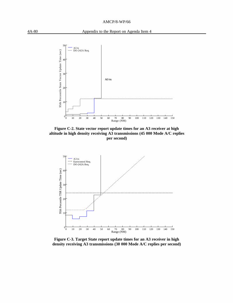
AMCP/8-WP/66
4A-80 Appendix to the Report on Agenda Item 4
0 10 20 30 40 50 60 70 80 90 100 110 120 130 140 150 0
10
20
30
40
50
95th
Per
cent
ile T
SR U
pdat
e T
ime
(sec
)
Range (NM)
A3 tx Eurocontrol Req. DO-242A Req.
Figure C-3. Target State report update times for an A3 receiver in highdensity receiving A3 transmissions (30 000 Mode A/C replies per second)
0 10 20 30 40 50 60 70 80 90 100 110 120 130 140 1500
10
20
30
40
50
95th
Per
cent
ile
Sta
te V
ecto
r U
pdat
e T
ime
(sec
)
Range (NM)
A3 tx
A3 txDO-242A Req.
Figure C-2. State vector report update times for an A3 receiver at highaltitude in high density receiving A3 transmissions (45 000 Mode A/C replies
per second)
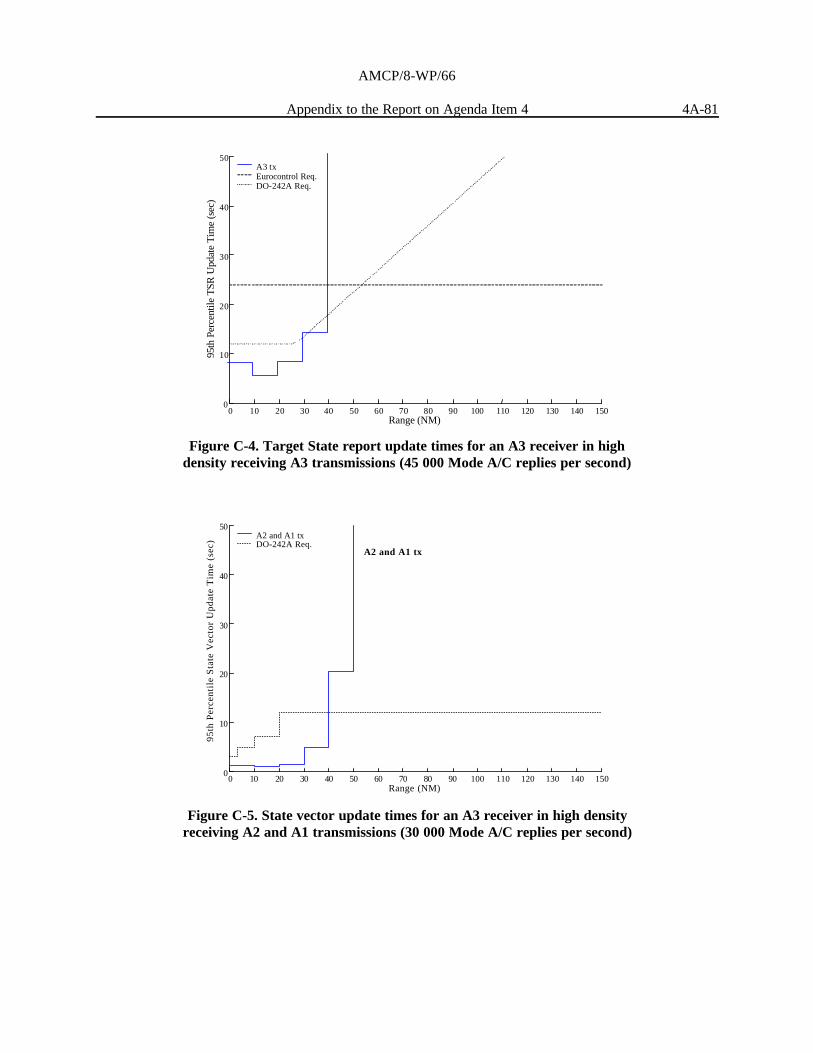
AMCP/8-WP/66
Appendix to the Report on Agenda Item 4 4A-81
0 10 20 30 40 50 60 70 80 90 100 110 120 130 140 150 0
10
20
30
40
50
95th
Per
cent
ile T
SR U
pdat
e T
ime
(sec
)
Range (NM)
A3 tx Eurocontrol Req. DO-242A Req.
Figure C-4. Target State report update times for an A3 receiver in highdensity receiving A3 transmissions (45 000 Mode A/C replies per second)
0 10 20 30 40 50 60 70 80 90 100 110 120 130 140 1500
10
20
30
40
50
95th
Per
cent
ile
Sta
te V
ecto
r U
pdat
e T
ime
(sec
)
Range (NM)
A2 and A1 tx
A2 and A1 txDO-242A Req.
Figure C-5. State vector update times for an A3 receiver in high densityreceiving A2 and A1 transmissions (30 000 Mode A/C replies per second)

AMCP/8-WP/66
4A-82 Appendix to the Report on Agenda Item 4
0 10 20 30 40 50 60 70 80 90 100 110 120 130 140 1500
10
20
30
40
50
95th
Per
cent
ile
Sta
te V
ecto
r U
pdat
e T
ime
(sec
)
Range (NM)
A2 and A1 tx
A2 and A1 txDO-242A Req.
Figure C-6. State vector update times for an A3 receiver at high altitude inhigh density receiving A2 and A1 transmissions (45 000 Mode A/C replies per
second)
0 10 20 30 40 50 60 70 80 90 100 110 120 130 140 150 0
10
20
30
40
50
95th
Per
cent
ile T
SR U
pdat
e T
ime
(sec
)
Range (NM)
A2 tx Eurocontrol Req. DO-242A Req.
Figure C-7. Target State report update times for an A3 receiver in highdensity receiving A2 transmissions (30 000 Mode A/C replies per second)

AMCP/8-WP/66
Appendix to the Report on Agenda Item 4 4A-83
0 10 20 30 40 50 60 70 80 90 100 110 120 130 140 150 0
10
20
30
40
50
95th
Per
cent
ile T
SR U
pdat
e T
ime
(sec
)
Range (NM)
A2 tx Eurocontrol Req. DO-242A Req.
Figure C-8. Target State report update times for an A3 receiver in highdensity receiving A2 transmissions (45 000 Mode A/C replies per second)
Figures C-9 and C-10 show 1 090 ES system performance in the low-density scenario. RTCADO-242A [Ref. 3] specifies the maximum ranges for air-air update rates required for A3 to 90 NM (120 NMdesired), while the Eurocontrol criteria continue to 150 NM. The RTCA DO-242A requirements for state vectorand TSR updates are shown as black dotted lines on the plots. The Eurocontrol extension to 150 NM is appliedto the state vector and TSR. Performance in compliance with requirements is indicated by results that are belowthe dotted and dashed lines.

AMCP/8-WP/66
4A-84 Appendix to the Report on Agenda Item 4
0 10 20 30 40 50 60 70 80 90 100 110 120 130 140 1500
10
20
30
40
50
95th
Per
cent
ile
Sta
te V
ecto
r U
pdat
e T
ime
(sec
)
Range (NM)
A3 tx
A3 txDO-242A Req.
Figure C-9. Target State report update times for an A3 receiver in alow-density scenario receiving A3 transmissions (5 000 Mode A/C replies per
second)
0 10 20 30 40 50 60 70 80 90 100 110 120 130 140 1500
10
20
30
40
50
95th
Per
cent
ile
TS
R U
pdat
e T
ime
(sec
)
Range (NM)
A3 txEurocontrol Req.DO-242A Req.
Figure C-10. Target State report update times for an A3 receiver in alow-density scenario receiving A3 transmissions (5 000 Mode A/C replies per
second)
— END —