Embed Size (px)
Citation preview

Appendix F –
Borescope Investigation of Pier E2 Rods Holes, SMR Reports (2011 and 2013)

September 17, 2014 Office of Structural Material
PROJECT INFORMATION
04-0120F4 Self-Anchored Suspension Bridge
SUBJECT
Borescope Investigation of Pier E2 Rod Holes – 2011
BACKGROUND A total of 288 ASTM A354 Gr. BD bearing and shear key anchor rods have been installed in Pier E2, per the contract requirements; 96 of these 3-inch hot-dip galvanized rods are shear key anchor rods that were embedded in concrete at Pier E2. The shear key anchor rods were fabricat-ed in 2008 and assembled inside pipe sleeves in Shear Keys S1 and S2 after release to the jobsite. The locations of the shear keys (S1 and S2) are highlighted in Figure 1. The area around the pipe sleeves was grouted five years later, in 2013.
Figure 1: Locations of Shear Keys S1 (left) and S2 (right) on Pier E2
As shown in Figure 2, the details of the rods in S1 and S2 are different from the details for the bearing anchor rods. The embedment of the shear key E2 rods in concrete prevents access from below. Prior to installation of the shear keys, the rods had to be flush with the Pier E2 top surface; therefore, pipe sleeves were installed below the bearing plate to allow for the rods to be temporarily lowered (Figures 3 and 4). The area inside the temporary pipe sleeve was to be grouted after the rods were raised to their final position during installation of the shear key.

September 17, 2014 Office of Structural Material
Figure 2: Cross-sectional view of shear key and shear key anchor rods setup
Figure 3: Anchor rod setup Figure 4: Temporary Pipe Sleeve Detail
After the Pier E2 concrete pour, the rod holes were left open, exposing them to atmospheric con-ditions and accumulation of debris. The Contractor extracted the water and used compressed air
Bearing rods pass all the way though the bent.
Shear key rods do not pass through the bent.
Temporary Pipe Sleeve
Rod in lowered position
Rod in final position
Shear key base
Grout holes
Grout tube
Bearing Plate
Bearing Plate

September 17, 2014 Office of Structural Material
to remove debris. In order to prevent future water and debris intrusion, the Contractor covered the holes with plywood. See Figures 5 and 6.
Figure 5: Extraction of water
Figure 6: Capped Rod Holes
Construction requested that METS inspect the interior of the rod holes to assess the condition of the rods.
DISCUSSIONS
Quality Assurance Associate Steel Inspector Jason Gramlick performed borescope inspections of various rods in Shear Keys S1 and S2 on Aug. 8, 2011, with a GE XL Go Videoprobe Bo-rescope. Prior to the borescope inspection of the anchor rod sleeve, an initial visual inspection of the accessible area was conducted. The visible part of the rod exhibited corrosion in the threads. No physical damage to the threads was documented (see Figure 7).
Figure 7: Exposed rod at Pier E2
As shown in Figures 8 through 13, the following issues were observed:
• Some grouting holes were clogged by debris. (Figures 8 and 9) • Based on the borescope images, the bottom of the rods exhibited white corrosion prod-
uct. Some of the rods indicated higher levels of oxidation at their bottom end suggesting direct exposure to water. (Figure 9)

September 17, 2014 Office of Structural Material
• Objects such as cigarette butts, U-bolts, and wood chips were found at the bottom of the holes, on top of the bearing plate. (Figures 10 and 11)
• Standing water was observed in some rod holes (Figure 12) and below the bearing plate (Figure 13)
Figure 8: Grout Hole Blocked
Figure 9: Debris on the Bearing Plate
Figure 10: Various Debris on the Bearing
Plate
Figure 11: Various Debris on the Bearing
Plate
Figure 52: Standing Water in the Rod Hole
Figure 63: Various Debris on the Bearing
Plate
Grout hole
Bearing plate
Bearing plate
Grout hole
Oxidation at the bottom of rod
Debris on the bearing plate
Blocked grout hole
Wood chips on bearing plate
Standing water & debris
Standing water
Bearing plate

September 17, 2014 Office of Structural Material
SUMMARY OF OBSERVATIONS During the random investigation performed with the borescope, the rods exhibited zinc corrosion products. Various types of debris were evident throughout the investigation. Standing water was observed in some locations. For any comments or questions, please contact the undersigned at 510-610-9054.
6-30-15 ________________________________ Aaron Prchlik, PE Structural Materials Representative Division of Engineering Services Materials, Engineering, and Testing Services Office of Structural Materials cc. Keith Hoffman, Gary Thomas, Mazen Wahbeh

September 17, 2014 Office of Structural Materials
PROJECT INFORMATION
04-0120F4 Self-Anchored Suspension Bridge
SUBJECT
Borescope Investigation of Pier E2 Rod Holes – 2013
BACKGROUND A total of 288 ASTM A354 Gr. BD bearing and shear key anchor rods have been installed in Pier E2. 96 of these 3-inch hot-dip galvanized rods are shear key anchor rods that were embed-ded in concrete. The rods were fabricated in 2008 and assembled inside pipe sleeves in Shear Keys S1 and S2. The area around the pipe sleeves was grouted five years later, in 2013. Once the grouting was complete, in Mar. 2013, thirty-two (32) of the shear key anchor rods frac-tured shortly after tensioning. The specific rods are highlighted in Figure 1. The top portions of the rods were extracted in segments for fracture analysis. It was not possible to retrieve the bot-tom fracture surfaces. The Department requested that METS investigate the interior of the rod holes with a borescope to evaluate the in-situ conditions and provide images of the fracture re-gion.
Figure 1: Locations of Failed Rods in Shear Keys S1 & S2
S1 S2

September 17, 2014 Office of Structural Materials
As shown in Figure 2, the details of the rods in S1 and S2 are different from the details for the bearing anchor rods. The embedment of the shear key rods in concrete prevents access from be-low. Prior to installation of the shear keys, the rods had to be flush with the pier E2 top surface. Temporary pipe sleeves were installed below the bearing plate to allow for the rods to be in-stalled in a lowered position (Figures 3 and 4). After the shear keys were installed, the rods were raised to their final position where the bottom nut was against the bearing plate and the top of the rod was tensioned against the shear key base. The area inside the temporary pipe sleeve was grouted after the rods were raised to their final position.
Figure 2: Cross-Sectional View of Shear Key and Bearing Anchor Rods
Bearing rods pass all the way though the bent.
Shear key rods do not pass through the bent.

September 17, 2014 Office of Structural Materials
Figure 3: Anchor rod setup Figure 4: Temporary Sleeve Detail
DISCUSSION
Borescope inspections were performed between Mar. 12 and Mar. 17, 2013 by Quality Assur-ance Inspectors Jason Gramlick and Scott Croff with a GE XL Go Video probe Borescope (Fig-ure 5). The camera at the tip of tube on the borescope was inserted into each of the rod holes while the direction of the camera lens was navigated to observe the in-situ condition of the por-tion of the rod still in the hole.
Figure 5: GE XL Go Video probe Borescope
Out of the thirty-two fractured rods, only five locations, as highlighted in Figure 6, were acces-sible for borescope inspection: S1A7, S1-G1, S2-H6, S2-A6, and S2-A8.
Bearing Plate
Bearing Plate
Temporary sleeve
Rod in lowered position
Rod in final position
Shear key base Grout hole
Grout tube

September 17, 2014 Office of Structural Materials
Figure 6: Borescope Inspection Locations in Shear Keys S1 and S2
S1 S2

September 17, 2014 Office of Structural Materials
Rod ID S2-H6 (Mar. 12, 2013) Standing water was observed as shown in Figure 7. The water is right below the bearing plate as shown in Figure 8.. A gap appeared to be between the fractured rod and the bearing plate as shown in Figure 9 suggesting movement of the assembly away from the bearing plate. The views of the borescope images are at cross section A-A of Figure 3.
Figure 7: S2-H6 borescope snapshot
Figure 8: S2-H6 borescope snapshot
Figure 9: S2-H6 borescope snapshot
Standing water Pipe sleeve wall
Bearing Plate
Bearing plate
Standing water
Standing water
Gap
Nut/Washer

September 17, 2014 Office of Structural Materials
Rod ID S2-A6 (Mar. 13, 2013) Contamination of the borescope lens reduced the range of visibility. The rod’s fracture surface was identified and was dry (Figures 10 and 11). Corrosion products were visible on the rod frac-ture surface (Figure 11). The threads exhibited rusting as well (Figure 12). The views of the bo-rescope images are at cross section A-A of Figure 3.
Figure 10: S2-A6 borescope snapshot
Figure 11: S2-A6 borescope snapshot
Figure 12: S2-A6 borescope snapshot
Rod ID S1-A7 (Mar. 14, 2013) Standing water was observed during the inspection. No fracture surface was visible. It appears that the nut had rotated and only the flats of the nut were visible (Figure 13). There are gaps be-tween the bearing plate and the spherical washer edge. The gaps vary in size, further suggesting the rotation of the nut as shown in Figure 14 and Figure 15. The views of the borescope images are at cross section A-A of Figure 3.
Rod surface
Pipe sleeve wall
Rod surface close-up, rusting visible
Visible rusting on the threads

September 17, 2014 Office of Structural Materials
Figure 73: S1-A7 borescope snapshot
Figure 14: S1-A7 borescope snapshot
Figure 85: S1-A7 borescope snapshot Rod ID S1-G1 (Mar. 17, 2013) The fractured rod was not submerged in water, but moisture was present (Figure 16). The cam-era lens was rotated to observe the threads on the rod and the nut and as shown in Figure 17; the threads exhibited rust deposits. The fracture surface was clearly visible. The nut appeared to be seated within the spherical washer (Figure 17). The views of the borescope images are at cross section A-A of Figure 3.
Figure 16: S1-G1 borescope snapshot
Figure 17: S1-G1 borescope snapshot
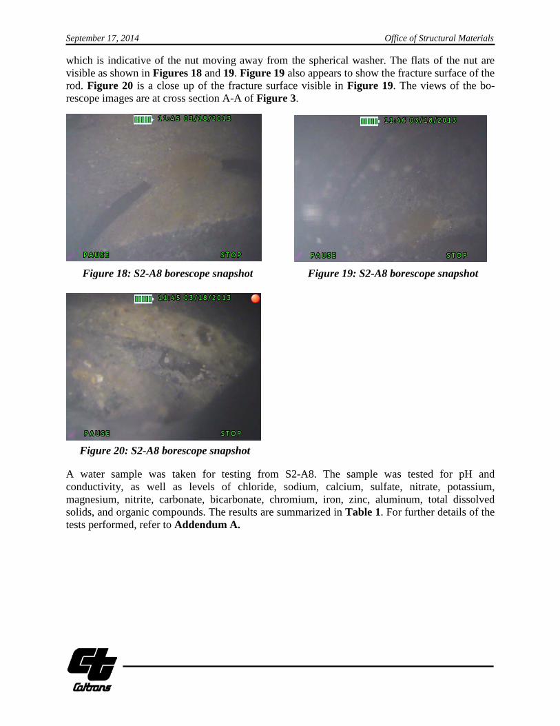
Rod ID S2-A8 (Mar. 18, 2013) Standing water was observed in the hole and the rod was submerged. Particulates in the water reduced clarity and visibility. A gap appeared between the spherical nut and the spherical washer
Spherical washer
Spherical nut edge
Moist Fracture surface
Washer
Nut thread
Fracture surface
Nut thread Washer
Large gap Nut flats
Spherical washer Spherical washer
September 17, 2014 Office of Structural Materials
which is indicative of the nut moving away from the spherical washer. The flats of the nut are visible as shown in Figures 18 and 19. Figure 19 also appears to show the fracture surface of the rod. Figure 20 is a close up of the fracture surface visible in Figure 19. The views of the bo-rescope images are at cross section A-A of Figure 3.
Figure 18: S2-A8 borescope snapshot Figure 19: S2-A8 borescope snapshot
Figure 20: S2-A8 borescope snapshot
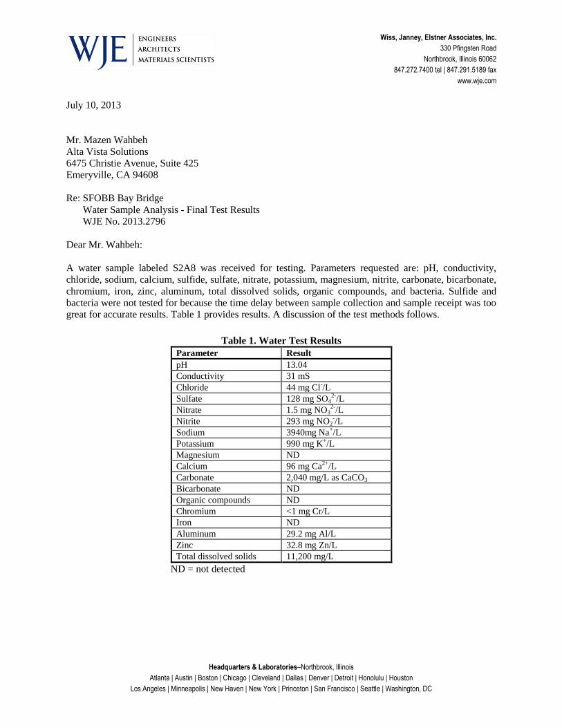
A water sample was taken for testing from S2-A8. The sample was tested for pH and conductivity, as well as levels of chloride, sodium, calcium, sulfate, nitrate, potassium, magnesium, nitrite, carbonate, bicarbonate, chromium, iron, zinc, aluminum, total dissolved solids, and organic compounds. The results are summarized in Table 1. For further details of the tests performed, refer to Addendum A.
Spherical nut flats
Spherical Washer
Gap Flats
Spherical Washer
Spherical face
Fracture surface
Fracture surface
Spherical face

September 17, 2014 Office of Structural Materials
Table 1: Summary of Water Sample Testing at WJE
SUMMARY OF OBSERVATIONS
In all but one of the inspected locations, standing water was identified in the bottom of the an-chor rod holes. In rod hole S2-A6, where water was not visible, corrosion was evident. In three locations, gaps were discovered between the washer and the spherical nut suggesting the nut had rotated. For any comments or questions, please contact the undersigned at 510-610-9054. ________________________________ Aaron Prchlik, PE Structural Materials Representative 6-30-15 Division of Engineering Services Materials, Engineering, and Testing Services Office of Structural Materials CC: Keith Hoffman, Gary Thomas, Mazen Wahbeh

September 17, 2014 Office of Structural Materials
Addendum A: Water Sample Analysis – Final Test Results
Wiss, Janney, Elstner Associates, Inc.
330 Pfingsten Road
Northbrook, Illinois 60062
847.272.7400 tel | 847.291.5189 fax
www.wje.com
Headquarters & Laboratories–Northbrook, Illinois
Atlanta | Austin | Boston | Chicago | Cleveland | Dallas | Denver | Detroit | Honolulu | Houston
Los Angeles | Minneapolis | New Haven | New York | Princeton | San Francisco | Seattle | Washington, DC
July 10, 2013
Mr. Mazen Wahbeh
Alta Vista Solutions
6475 Christie Avenue, Suite 425
Emeryville, CA 94608
Re: SFOBB Bay Bridge
Water Sample Analysis - Final Test Results
WJE No. 2013.2796
Dear Mr. Wahbeh:
A water sample labeled S2A8 was received for testing. Parameters requested are: pH, conductivity,
chloride, sodium, calcium, sulfide, sulfate, nitrate, potassium, magnesium, nitrite, carbonate, bicarbonate,
chromium, iron, zinc, aluminum, total dissolved solids, organic compounds, and bacteria. Sulfide and
bacteria were not tested for because the time delay between sample collection and sample receipt was too
great for accurate results. Table 1 provides results. A discussion of the test methods follows.
Table 1. Water Test Results
Parameter Result
pH 13.04
Conductivity 31 mS
Chloride 44 mg Cl-/L
Sulfate 128 mg SO42-
/L
Nitrate 1.5 mg NO32-
/L
Nitrite 293 mg NO2-/L
Sodium 3940mg Na+/L
Potassium 990 mg K+/L
Magnesium ND
Calcium 96 mg Ca2+
/L
Carbonate 2,040 mg/L as CaCO3
Bicarbonate ND
Organic compounds ND
Chromium <1 mg Cr/L
Iron ND
Aluminum 29.2 mg Al/L
Zinc 32.8 mg Zn/L
Total dissolved solids 11,200 mg/L
ND = not detected

Mr. Mazen Wahbeh
Alta Vista Solutions
July 10, 2013
Page 2
Discussion of Test Methods
pH - pH was measured using a pH meter with an electrode that had been calibrated with pH 7, pH 13 and
pH 4 standard buffer solutions.
Conductivity - Conductivity was measured with an Omega CDH-80 MS conductivity meter. The meter is
factory calibrated and was checked with 100µS standard conductivity solution.
Chloride, Sulfate, Nitrate, Nitrite - Anion concentrations were determined using a Dionex ICS 2000 ion
chromatograph using hydroxide eluent. Calibration curves were derived using standards for chloride,
sulfate, nitrate, and nitrite (as well as fluoride, bromide and phosphate). The sample was diluted as
necessary to bring the concentration of each analyte anion into the calibration range. The concentration of
a given analyte is determined by comparison to a curve fit of the standards.
Sodium, Potassium, Magnesium, Calcium - Cation concentrations were determined using a Dionex ICS
2000 ion chromatograph using methanesulfonic acid eluent. Calibration curves were derived using
standards for sodium, potassium, magnesium, and (as well as lithium and ammonium). The sample was
diluted as necessary to bring the concentration of each analyte anion into the calibration range. The
concentration of a given analyte is determined by comparison to a curve fit of the standards.
Carbonate and Bicarbonate - Carbonate and bicarbonate concentrations were measured by titration with
sulfuric acid. Carbonate and bicarbonate content is calculated after titration to different pH endpoints.
Organic Compounds - Organic compounds were analyzed for by direct injection of a portion of the
water sample into a Perkin Elmer gas chromatograph with mass spectrometer detector. This technique,
using the Restek 5Sil-MS column with a 1 micron film thickness has proven successful at detecting a
wide range of compounds in the past. No compounds were detected after duplicate injections of undiluted
water.
Aluminum, Chromium, Zinc - Analysis using atomic absorption of an acidified sample was anticipated.
However, upon addition of acid, a precipitate formed. Analysis of the precipitate using scanning electron
microscopy with energy dispersive x-ray spectroscopy indicated the presence of aluminum and zinc, but
not iron or chromium. For analysis of aluminum, chromium and zinc, dried material remaining from the
total dissolved solids test was fused with lithium metaborate to create a specimen that could be dissolved
without precipitation. This solution of the fused sample was used for analysis using atomic absorption
spectroscopy.
Iron - Analysis using atomic absorption spectroscopy of an acidified sample was performed. A
precipitate, which did not contain detectable iron, was filtered from the solution.
Total Dissolved Solids - A portion of the water sample was filtered to remove solids. The filtrate was
heated to remove the water, and the total dissolved solids determined gravimetrically.

Mr. Mazen Wahbeh
Alta Vista Solutions
July 10, 2013
Page 3
Thank you for the opportunity to work with you on this project. If you have any questions, please do not
hesitate to contact us.
Sincerely,
WISS, JANNEY, ELSTNER ASSOCIATES, INC.
Kimberley A. Steiner
Senior Associate
F. Dirk Heidbrink
Project Manager