Embed Size (px)
Citation preview
APPENDIX J
CONSTRUCTION

ID
1
2
3
4
5
6
7
8
9
10
11
12
13
14
15
16
17
18
19
20
East Slurry Wall Zone 4
East Slurry Wall Zone 5
Demolition Zone 4
Demolition Zone 5
Excavation Zone 4
Excavation Zone 5
Northwest Quadrant Sub-Grade Retail
Freedom Tower Structural Framing
Freedom Tower Fitout & Curtain Wall
Memorial, Open Space, Cultural Space
Southeast Quadrant Zone 4 Foundation & Below-Grade Retail
Northeast Quadrant Zone 5 Foundation & Below-Grade Retail
East Bathtub Retail Above-Grade Fitout
Towers 2,3 & 4 Office Floor Construction Structural Framing
Towers 2,3, & 4 Fitout & Curtain Wall
Southern Site Slurry Wall
Southern Site Excavation
Southern Site Sub-Grade Construction
Deutsche Bank Demolition
Tower 5
Q4 Q1 Q2 Q3 Q4 Q1 Q2 Q3 Q4 Q1 Q2 Q3 Q4 Q1 Q2 Q3 Q4 Q1 Q2 Q3 Q4 Q1 Q2 Q3 Q4 Q1 Q2 Q3 Q4 Q1 Q2 Q3 Q4 Q1 Q2 Q3 Q4 Q1 Q2 Q3 Q4 Q1 Q2 Q3 Q4 Q1 Q2 Q32004 2005 2006 2007 2008 2009 2010 2011 2012 2013 2014 2015
Appendix J-1 World Trade Center Construction Phasing
Source: The Louis Berger Group, Inc., 2003
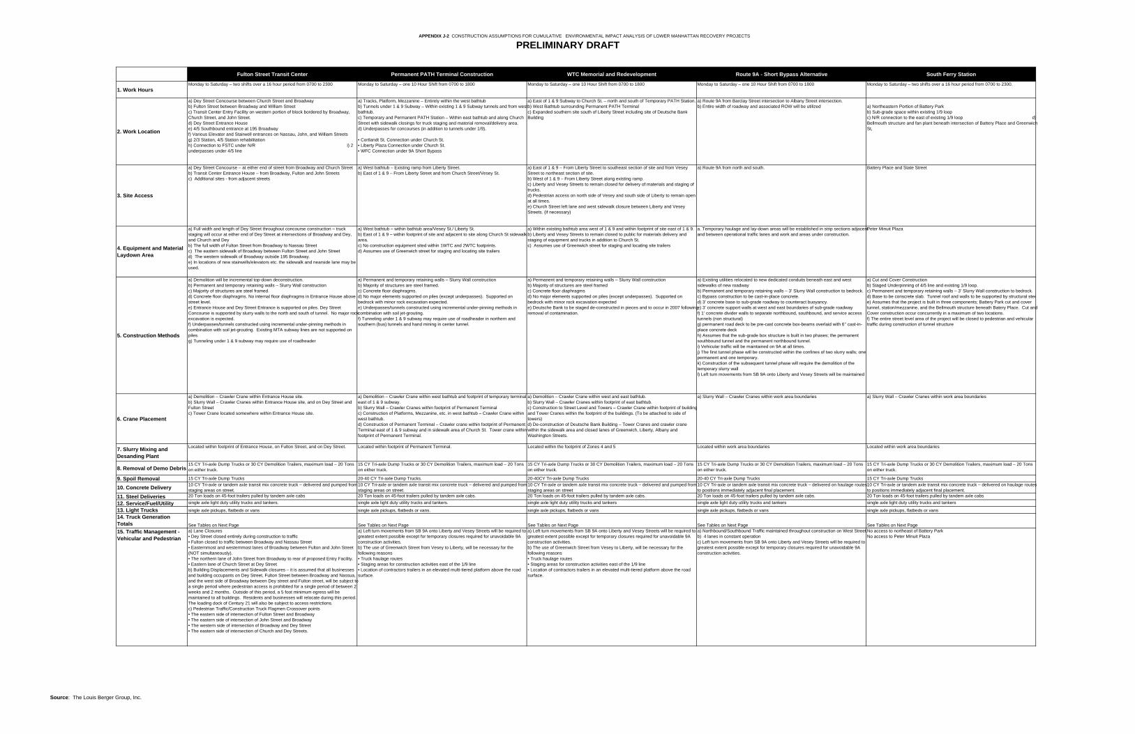
APPENDIX J-2 CONSTRUCTION ASSUMPTIONS FOR CUMULATIVE ENVIRONMENTAL IMPACT ANALYSIS OF LOWER MANHATTAN RECOVERY PROJECTS
PRELIMINARY DRAFT
Fulton Street Transit Center Permanent PATH Terminal Construction WTC Memorial and Redevelopment Route 9A - Short Bypass Alternative South Ferry Station
1. Work HoursMonday to Saturday – two shifts over a 16 hour period from 0700 to 2300 Monday to Saturday – one 10 Hour Shift from 0700 to 1800 Monday to Saturday – one 10 Hour Shift from 0700 to 1800 Monday to Saturday – one 10 Hour Shift from 0700 to 1800 Monday to Saturday – two shifts over a 16 hour period from 0700 to 2300.
2. Work Location
a) Dey Street Concourse between Church Street and Broadwayb) Fulton Street between Broadway and William Streetc) Transit Center Entry Facility on western portion of block bordered by Broadway, Church Street, and John Street.d) Dey Street Entrance Housee) 4/5 Southbound entrance at 195 Broadwayf) Various Elevator and Stairwell entrances on Nassau, John, and William Streetsg) 2/3 Station, 4/5 Station rehabilitation h) Connection to FSTC under N/R i) 2 underpasses under 4/5 line
a) Tracks, Platform, Mezzanine – Entirely within the west bathtubb) Tunnels under 1 & 9 Subway – Within existing 1 & 9 Subway tunnels and from west bathtub.c) Temporary and Permanent PATH Station – Within east bathtub and along Church Street with sidewalk closings for truck staging and material removal/delivery area.d) Underpasses for concourses (in addition to tunnels under 1/9).
• Cortlandt St. Connection under Church St.• Liberty Plaza Connection under Church St.• WFC Connection under 9A Short Bypass
a) East of 1 & 9 Subway to Church St. – north and south of Temporary PATH Station.b) West Bathtub surrounding Permanent PATH Terminal c) Expanded southern site south of Liberty Street including site of Deutsche Bank Building
a) Route 9A from Barclay Street intersection to Albany Street intersection.b) Entire width of roadway and associated ROW will be utilized a) Northeastern Portion of Battery Park
b) Sub-grade space within existing 1/9 loopc) N/R connection to the east of existing 1/9 loop d) Bellmouth structure and fan plant beneath intersection of Battery Place and Greenwich St,
3. Site Access
a) Dey Street Concourse – at either end of street from Broadway and Church Streetb) Transit Center Entrance House – from Broadway, Fulton and John Streets c) Additional sites - from adjacent streets
a) West bathtub – Existing ramp from Liberty Street.b) East of 1 & 9 – From Liberty Street and from Church Street/Vesey St.
a) East of 1 & 9 – From Liberty Street to southeast section of site and from Vesey Street to northeast section of site.b) West of 1 & 9 – From Liberty Street along existing ramp.c) Liberty and Vesey Streets to remain closed for delivery of materials and staging of trucks. d) Pedestrian access on north side of Vesey and south side of Liberty to remain open at all times.e) Church Street left lane and west sidewalk closure between Liberty and Vesey Streets. (if necessary)
a) Route 9A from north and south. Battery Place and State Street
4. Equipment and Material Laydown Area
a) Full width and length of Dey Street throughout concourse construction – truck staging will occur at either end of Dey Street at intersections of Broadway and Dey, and Church and Deyb) The full width of Fulton Street from Broadway to Nassau Streetc) The eastern sidewalk of Broadway between Fulton Street and John Streetd) The western sidewalk of Broadway outside 195 Broadway. e) In locations of new stairwells/elevators etc. the sidewalk and nearside lane may be used.
a) West bathtub – within bathtub area/Vesey St./ Liberty St.b) East of 1 & 9 – within footprint of site and adjacent to site along Church St sidewalk area.c) No construction equipment sited within 1WTC and 2WTC footprints. d) Assumes use of Greenwich street for staging and locating site trailers
a) Within existing bathtub area west of 1 & 9 and within footprint of site east of 1 & 9. b) Liberty and Vesey Streets to remain closed to public for materials delivery and staging of equipment and trucks in addition to Church St. c) Assumes use of Greenwich street for staging and locating site trailers
a. Temporary haulage and lay-down areas will be established in strip sections adjacent and between operational traffic lanes and work and areas under construction.
Peter Minuit Plaza
5. Construction Methods
a) Demolition will be incremental top-down deconstruction.b) Permanent and temporary retaining walls – Slurry Wall constructionc) Majority of structures are steel framed.d) Concrete floor diaphragms. No internal floor diaphragms in Entrance House above street level.e) Entrance House and Dey Street Entrance is supported on piles. Dey Street Concourse is supported by slurry walls to the north and south of tunnel. No major rock excavation is expected.f) Underpasses/tunnels constructed using incremental under-pinning methods in combination with soil jet-grouting. Existing MTA subway lines are not supported on piles.g) Tunneling under 1 & 9 subway may require use of roadheader
a) Permanent and temporary retaining walls – Slurry Wall constructionb) Majority of structures are steel framed.c) Concrete floor diaphragms.d) No major elements supported on piles (except underpasses). Supported on bedrock with minor rock excavation expected.e) Underpasses/tunnels constructed using incremental under-pinning methods in combination with soil jet-grouting.f) Tunneling under 1 & 9 subway may require use of roadheader in northern and southern (bus) tunnels and hand mining in center tunnel.
a) Permanent and temporary retaining walls – Slurry Wall constructionb) Majority of structures are steel framedc) Concrete floor diaphragmsd) No major elements supported on piles (except underpasses). Supported on bedrock with minor rock excavation expectede) Deutsche Bank to be staged de-constructed in pieces and to occur in 2007 following removal of contamination.
a) Existing utilities relocated to new dedicated conduits beneath east and west sidewalks of new roadwayb) Permanent and temporary retaining walls – 3’ Slurry Wall construction to bedrock. c) Bypass construction to be cast-in-place concrete. d) 3’ concrete base to sub-grade roadway to counteract buoyancy.e) 3’ concrete support walls at west and east boundaries of sub-grade roadwayf) 1’ concrete divider walls to separate northbound, southbound, and service access tunnels (non structural)g) permanent road deck to be pre-cast concrete box-beams overlaid with 6’’ cast-in-place concrete deck h) Assumes that the sub-grade box structure is built in two phases; the permanent southbound tunnel and the permanent northbound tunnel.i) Vehicular traffic will be maintained on 9A at all times. j) The first tunnel phase will be constructed within the confines of two slurry walls; one permanent and one temporary. k) Construction of the subsequent tunnel phase will require the demolition of the temporary slurry wall l) Left turn movements from SB 9A onto Liberty and Vesey Streets will be maintained
a) Cut and Cover Constructionb) Staged Underpinning of 4/5 line and existing 1/9 loop.c) Permanent and temporary retaining walls – 3’ Slurry Wall construction to bedrock. d) Base to be conscrete slab. Tunnel roof and walls to be supported by structural steee) Assumes that the project is built in three components; Battery Park cut and cover tunnel, station/mezzanine, and the Bellmouth structure beneath Batery Place. Cut and Cover construction occur concurrently in a maximum of two locations.f) The entire street level area of the project will be closed to pedestrian and vehicular traffic during construction of tunnel structure
6. Crane Placement
a) Demolition – Crawler Crane within Entrance House site.b) Slurry Wall – Crawler Cranes within Entrance House site, and on Dey Street and Fulton Streetc) Tower Crane located somewhere within Entrance House site.
a) Demolition – Crawler Crane within west bathtub and footprint of temporary terminal east of 1 & 9 subway.b) Slurry Wall – Crawler Cranes within footprint of Permanent Terminalc) Construction of Platforms, Mezzanine, etc. in west bathtub – Crawler Crane within west bathtub.d) Construction of Permanent Terminal – Crawler crane within footprint of Permanent Terminal east of 1 & 9 subway and in sidewalk area of Church St. Tower crane within footprint of Permanent Terminal.
a) Demolition – Crawler Crane within west and east bathtub. b) Slurry Wall – Crawler Cranes within footprint of east bathtub.c) Construction to Street Level and Towers – Crawler Crane within footprint of building and Tower Cranes within the footprint of the buildings. (To be attached to side of towers)d) De-construction of Deutsche Bank Building – Tower Cranes and crawler crane within the sidewalk area and closed lanes of Greenwich, Liberty, Albany and Washington Streets.
a) Slurry Wall – Crawler Cranes within work area boundaries a) Slurry Wall – Crawler Cranes within work area boundaries
7. Slurry Mixing and Desanding Plant
Located within footprint of Entrance House, on Fulton Street, and on Dey Street. Located within footprint of Permanent Terminal. Located within the footprint of Zones 4 and 5 Located within work area boundaries Located within work area boundaries
8. Removal of Demo Debris15 CY Tri-axle Dump Trucks or 30 CY Demolition Trailers, maximum load – 20 Tons on either truck.
15 CY Tri-axle Dump Trucks or 30 CY Demolition Trailers, maximum load – 20 Tons on either truck.
15 CY Tri-axle Dump Trucks or 30 CY Demolition Trailers, maximum load – 20 Tons on either truck.
15 CY Tri-axle Dump Trucks or 30 CY Demolition Trailers, maximum load – 20 Tons on either truck.
15 CY Tri-axle Dump Trucks or 30 CY Demolition Trailers, maximum load – 20 Tons on either truck.
9. Spoil Removal 15 CY Tri-axle Dump Trucks 20-40 CY Tri-axle Dump Trucks. 20-40CY Tri-axle Dump Trucks 20-40 CY Tri-axle Dump Trucks 15 CY Tri-axle Dump Trucks
10. Concrete Delivery 10 CY Tri-axle or tandem axle transit mix concrete truck – delivered and pumped from staging areas on street.
10 CY Tri-axle or tandem axle transit mix concrete truck – delivered and pumped from staging areas on street.
10 CY Tri-axle or tandem axle transit mix concrete truck – delivered and pumped from staging areas on street
10 CY Tri-axle or tandem axle transit mix concrete truck – delivered on haulage routes to positions immediately adjacent final placement.
10 CY Tri-axle or tandem axle transit mix concrete truck – delivered on haulage routes to positions immediately adjacent final placement.
11. Steel Deliveries 20 Ton loads on 45-foot trailers pulled by tandem axle cabs 20 Ton loads on 45-foot trailers pulled by tandem axle cabs. 20 Ton loads on 45-foot trailers pulled by tandem axle cabs. 20 Ton loads on 45-foot trailers pulled by tandem axle cabs. 20 Ton loads on 45-foot trailers pulled by tandem axle cabs
12. Service/Fuel/Utility single axle light duty utility trucks and tankers. single axle light duty utility trucks and tankers. single axle light duty utility trucks and tankers single axle light duty utility trucks and tankers single axle light duty utility trucks and tankers
13. Light Trucks single axle pickups, flatbeds or vans single axle pickups, flatbeds or vans. single axle pickups, flatbeds or vans single axle pickups, flatbeds or vans single axle pickups, flatbeds or vans14. Truck Generation Totals See Tables on Next Page See Tables on Next Page See Tables on Next Page See Tables on Next Page See Tables on Next Page15. Traffic Management - Vehicular and Pedestrian
a) Lane Closures• Dey Street closed entirely during construction to traffic• Fulton closed to traffic between Broadway and Nassau Street• Easternmost and westernmost lanes of Broadway between Fulton and John Street (NOT simultaneously).• The northern lane of John Street from Broadway to rear of proposed Entry Facility. • Eastern lane of Church Street at Dey Streetb) Building Displacements and Sidewalk closures – it is assumed that all businesses and building occupants on Dey Street, Fulton Street between Broadway and Nassua, and the west side of Broadway between Dey street and Fulton street, will be subject to a single period where pedestrian access is prohibited for a single period of between 2 weeks and 2 months. Outside of this period, a 5 foot minimum egress will be maintained to all buildings. Residents and businesses will relocate during this period. The loading dock of Century 21 will also be subject to access restrictions.c) Pedestrian Traffic/Construction Truck Flagmen Crossover points • The eastern side of intersection of Fulton Street and Broadway• The eastern side of intersection of John Street and Broadway • The western side of intersection of Broadway and Dey Street• The eastern side of intersection of Church and Dey Streets.
a) Left turn movements from SB 9A onto Liberty and Vesey Streets will be required to greatest extent possible except for temporary closures required for unavoidable 9A construction activities.b) The use of Greenwich Street from Vesey to Liberty, will be necessary for the following reasons• Truck haulage routes • Staging areas for construction activities east of the 1/9 line• Location of contractors trailers in an elevated multi-tiered platform above the road surface.
a) Left turn movements from SB 9A onto Liberty and Vesey Streets will be required to greatest extent possible except for temporary closures required for unavoidable 9A construction activities.b) The use of Greenwich Street from Vesey to Liberty, will be necessary for the following reasons• Truck haulage routes • Staging areas for construction activities east of the 1/9 line• Location of contractors trailers in an elevated multi-tiered platform above the road surface.
a) Northbound/Southbound Traffic maintained throughout construction on West Street.b) 4 lanes in constant operation c) Left turn movements from SB 9A onto Liberty and Vesey Streets will be required to greatest extent possible except for temporary closures required for unavoidable 9A construction activities.
No access to northeast of Battery Park No access to Peter Minuit Plaza
Source: The Louis Berger Group, Inc.
Appendix J. Construction
J-3
APPENDIX J-3 CONSTRUCTION METHODS AND IMPACTS
WTC MEMORIAL AND REDEVELOPMENT
CONSTRUCTION TRAFFIC AND CONSTRUCTION EQUIPMENT
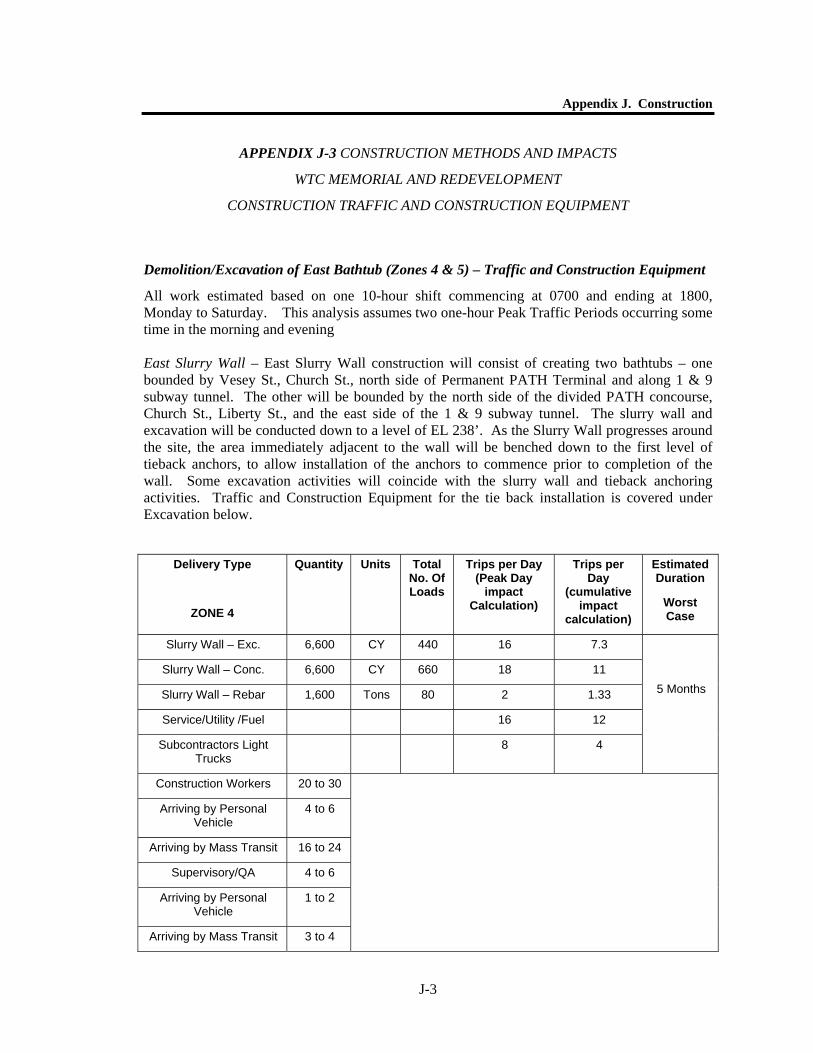
Demolition/Excavation of East Bathtub (Zones 4 & 5) – Traffic and Construction Equipment
All work estimated based on one 10-hour shift commencing at 0700 and ending at 1800, Monday to Saturday. This analysis assumes two one-hour Peak Traffic Periods occurring some time in the morning and evening East Slurry Wall – East Slurry Wall construction will consist of creating two bathtubs – one bounded by Vesey St., Church St., north side of Permanent PATH Terminal and along 1 & 9 subway tunnel. The other will be bounded by the north side of the divided PATH concourse, Church St., Liberty St., and the east side of the 1 & 9 subway tunnel. The slurry wall and excavation will be conducted down to a level of EL 238’. As the Slurry Wall progresses around the site, the area immediately adjacent to the wall will be benched down to the first level of tieback anchors, to allow installation of the anchors to commence prior to completion of the wall. Some excavation activities will coincide with the slurry wall and tieback anchoring activities. Traffic and Construction Equipment for the tie back installation is covered under Excavation below.
Delivery Type
ZONE 4
Quantity Units Total No. Of Loads
Trips per Day (Peak Day
impact Calculation)
Trips per Day
(cumulative impact
calculation)
Estimated Duration
Worst Case
Slurry Wall – Exc. 6,600 CY 440 16 7.3
Slurry Wall – Conc. 6,600 CY 660 18 11
Slurry Wall – Rebar 1,600 Tons 80 2 1.33
Service/Utility /Fuel 16 12
Subcontractors Light Trucks
8 4
5 Months
Construction Workers 20 to 30
Arriving by Personal Vehicle
4 to 6
Arriving by Mass Transit 16 to 24
Supervisory/QA 4 to 6
Arriving by Personal Vehicle
1 to 2
Arriving by Mass Transit 3 to 4
World Trade Center Memorial and Redevelopment Plan GEIS
J-4
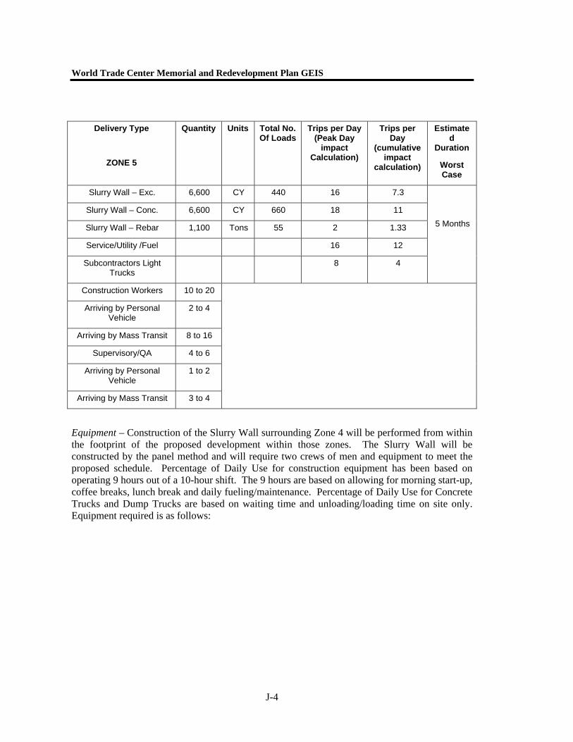
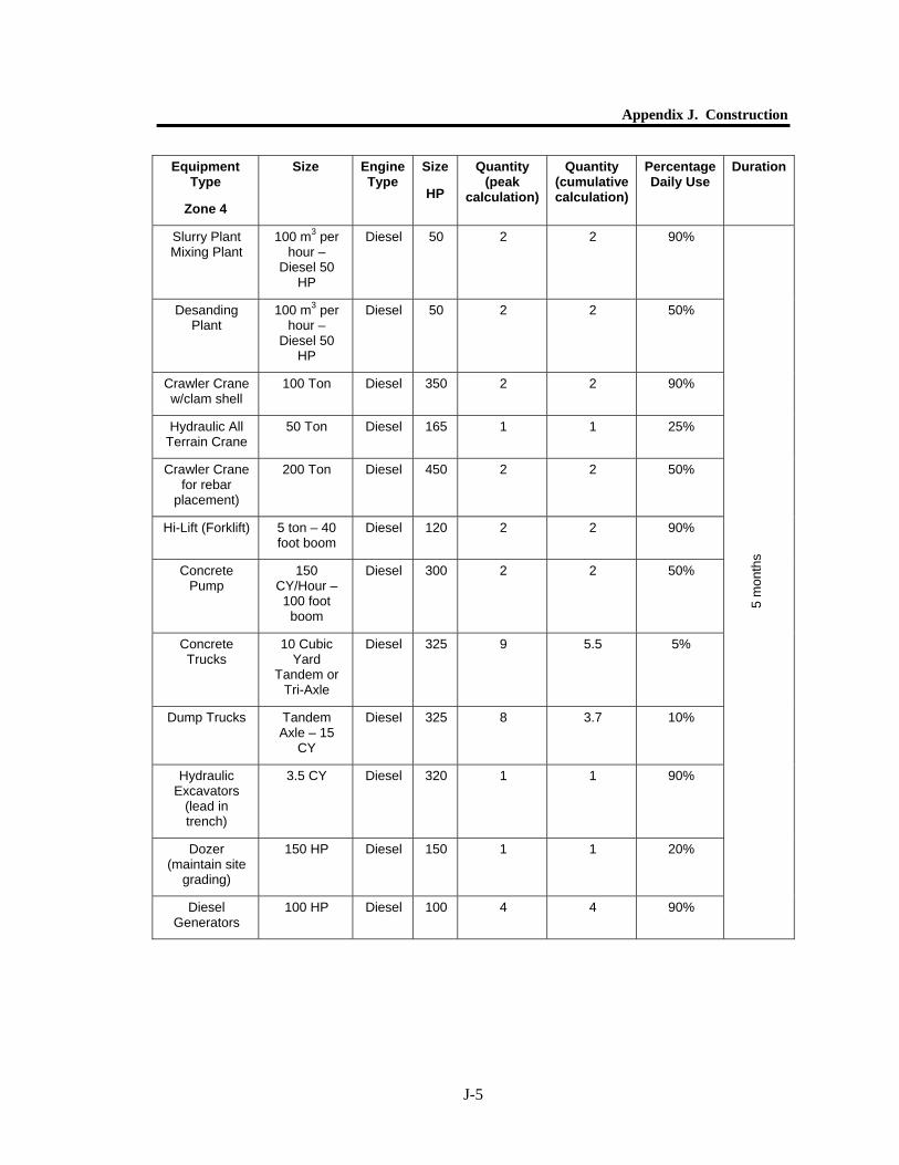
Equipment – Construction of the Slurry Wall surrounding Zone 4 will be performed from within the footprint of the proposed development within those zones. The Slurry Wall will be constructed by the panel method and will require two crews of men and equipment to meet the proposed schedule. Percentage of Daily Use for construction equipment has been based on operating 9 hours out of a 10-hour shift. The 9 hours are based on allowing for morning start-up, coffee breaks, lunch break and daily fueling/maintenance. Percentage of Daily Use for Concrete Trucks and Dump Trucks are based on waiting time and unloading/loading time on site only. Equipment required is as follows:
Delivery Type
ZONE 5
Quantity Units Total No. Of Loads
Trips per Day (Peak Day
impact Calculation)
Trips per Day
(cumulative impact
calculation)
Estimated
Duration
Worst Case
Slurry Wall – Exc. 6,600 CY 440 16 7.3
Slurry Wall – Conc. 6,600 CY 660 18 11
Slurry Wall – Rebar 1,100 Tons 55 2 1.33
Service/Utility /Fuel 16 12
Subcontractors Light Trucks
8 4
5 Months
Construction Workers 10 to 20
Arriving by Personal Vehicle
2 to 4
Arriving by Mass Transit 8 to 16
Supervisory/QA 4 to 6
Arriving by Personal Vehicle
1 to 2
Arriving by Mass Transit 3 to 4
Appendix J. Construction
J-5
Equipment Type
Zone 4
Size Engine Type
Size
HP
Quantity (peak
calculation)
Quantity (cumulative calculation)
Percentage Daily Use
Duration
Slurry Plant Mixing Plant
100 m3 per hour –
Diesel 50 HP
Diesel 50 2 2 90%
Desanding Plant
100 m3 per hour –
Diesel 50 HP
Diesel 50 2 2 50%
Crawler Crane w/clam shell
100 Ton Diesel 350 2 2 90%
Hydraulic All Terrain Crane
50 Ton Diesel 165 1 1 25%
Crawler Crane for rebar
placement)
200 Ton Diesel 450 2 2 50%
Hi-Lift (Forklift) 5 ton – 40 foot boom
Diesel 120 2 2 90%
Concrete Pump
150 CY/Hour – 100 foot
boom
Diesel 300 2 2 50%
Concrete Trucks
10 Cubic Yard
Tandem or Tri-Axle
Diesel 325 9 5.5 5%
Dump Trucks Tandem Axle – 15
CY
Diesel 325 8 3.7 10%
Hydraulic Excavators
(lead in trench)
3.5 CY Diesel 320 1 1 90%
Dozer (maintain site
grading)
150 HP Diesel 150 1 1 20%
Diesel Generators
100 HP Diesel 100 4 4 90%
5 m
onth
s
World Trade Center Memorial and Redevelopment Plan GEIS
J-6
Equipment Type
Zone 5
Size Engine Type
Size
HP
Quantity (peak
calculation)
Quantity (cumulative calculation)
Percentage Daily Use
Duration
Slurry Plant Mixing Plant
100 m3 per hour –
Diesel 50 HP
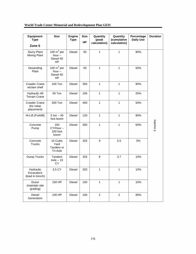
Diesel 50 1 1 90%
Desanding Plant
100 m3 per hour –
Diesel 50 HP
Diesel 50 1 1 50%
Crawler Crane w/clam shell
100 Ton Diesel 350 1 1 90%
Hydraulic All Terrain Crane
50 Ton Diesel 165 1 1 25%
Crawler Crane (for rebar
placement)
200 Ton Diesel 450 1 1 50%
Hi-Lift (Forklift) 5 ton – 40 foot boom
Diesel 120 1 1 90%
Concrete Pump
150 CY/Hour – 100 foot
boom
Diesel 300 1 1 50%
Concrete Trucks
10 Cubic Yard
Tandem or Tri-Axle
Diesel 325 9 5.5 5%
Dump Trucks Tandem Axle – 15
CY
Diesel 325 8 3.7 10%
Hydraulic Excavators
(lead in trench)
3.5 CY Diesel 320 1 1 10%
Dozer (maintain site
grading)
150 HP Diesel 150 1 1 10%
Diesel Generators
100 HP Diesel 100 2 2 90%
5 m
onth
s
Appendix J. Construction
J-7
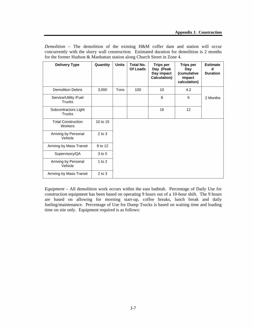
Demolition – The demolition of the existing H&M coffer dam and station will occur concurrently with the slurry wall construction. Estimated duration for demolition is 2 months for the former Hudson & Manhattan station along Church Street in Zone 4.
Equipment – All demolition work occurs within the east bathtub. Percentage of Daily Use for construction equipment has been based on operating 9 hours out of a 10-hour shift. The 9 hours are based on allowing for morning start-up, coffee breaks, lunch break and daily fueling/maintenance. Percentage of Use for Dump Trucks is based on waiting time and loading time on site only. Equipment required is as follows:
Delivery Type Quantity Units Total No. Of Loads
Trips per Day (Peak Day impact Calculation)
Trips per Day
(cumulative impact
calculation)
Estimated
Duration
Demolition Debris 3,000 Tons 100 10 4.2
Service/Utility /Fuel Trucks
8 6
Subcontractors Light Trucks
16 12
2 Months
Total Construction Workers
10 to 15
Arriving by Personal Vehicle
2 to 3
Arriving by Mass Transit 8 to 12
Supervisory/QA 3 to 5
Arriving by Personal Vehicle
1 to 2
Arriving by Mass Transit 2 to 3

World Trade Center Memorial and Redevelopment Plan GEIS
J-8
Equipment Type
Size Engine Type
Size
HP
Quantity (peak
calculation)
Quantity (cumulative calculation)
Percentage Daily Use
Duration
Hydraulic All Terrain Crane
50 Ton Diesel 165 1 1 50%
Hydraulic Excavator
w/Hoe Ram
3.5 Cubic Yard
Diesel 320 4 4 90%
Hydraulic Excavator w/Thumb
3.5 Cubic Yard
Diesel 320 1 1 90%
Hydraulic Excavator w/Grapple
3.5 Cubic Yard
Diesel 320 1 1 90%
Hydraulic Excavator w/Shear
3.5 Cubic Yard
Diesel 320 1 1 50%
Track Loader w/Waste
Handling Bucket
5.5 Cubic Yard
Diesel 160 1 1 90%
Dump Trucks Tandem Axle – 15
CY
Diesel 325 5 2.1 10%
Air Compressor for Pavement
Breakers
1600 CFM Diesel 460 1 1 50%
Pavement Breakers
90 lbs. 4 4 50%
2 m
onth
s
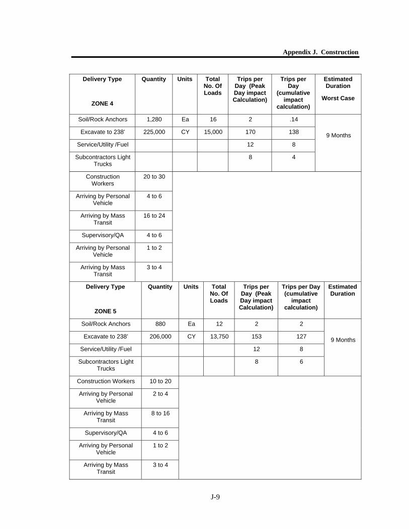
Excavation – After completion of the east slurry wall construction, the east bathtub will be created by excavating within the slurry walls to bedrock at EL 238’. The area immediately adjacent to the slurry walls will be benched to allow the installation of the tieback anchors for temporary support of the slurry wall during construction of the basement levels of the development. The soil excavation can continue in the northern central and southern central portions of the bathtub, zones 4 and 5 respectively. Areas immediately adjacent to the slurry wall will be conducted last until the final row of tieback anchors has been completed.
Appendix J. Construction
J-9
Delivery Type
ZONE 4
Quantity Units Total No. Of Loads
Trips per Day (Peak Day impact Calculation)
Trips per Day
(cumulative impact
calculation)
Estimated Duration
Worst Case
Soil/Rock Anchors 1,280 Ea 16 2 .14
Excavate to 238’ 225,000 CY 15,000 170 138
Service/Utility /Fuel 12 8
Subcontractors Light Trucks
8 4
9 Months
Construction Workers
20 to 30
Arriving by Personal Vehicle
4 to 6
Arriving by Mass Transit
16 to 24
Supervisory/QA 4 to 6
Arriving by Personal Vehicle
1 to 2
Arriving by Mass Transit
3 to 4
Delivery Type
ZONE 5
Quantity Units Total No. Of Loads
Trips per Day (Peak Day impact Calculation)
Trips per Day (cumulative
impact calculation)
Estimated Duration
Soil/Rock Anchors 880 Ea 12 2 2
Excavate to 238’ 206,000 CY 13,750 153 127
Service/Utility /Fuel 12 8
Subcontractors Light Trucks
8 6
9 Months
Construction Workers 10 to 20
Arriving by Personal Vehicle
2 to 4
Arriving by Mass Transit
8 to 16
Supervisory/QA 4 to 6
Arriving by Personal Vehicle
1 to 2
Arriving by Mass Transit
3 to 4
World Trade Center Memorial and Redevelopment Plan GEIS
J-10
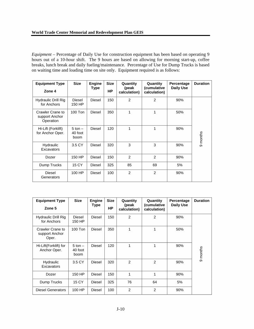
Equipment – Percentage of Daily Use for construction equipment has been based on operating 9 hours out of a 10-hour shift. The 9 hours are based on allowing for morning start-up, coffee breaks, lunch break and daily fueling/maintenance. Percentage of Use for Dump Trucks is based on waiting time and loading time on site only. Equipment required is as follows:
Equipment Type
Zone 4
Size Engine Type
Size
HP
Quantity (peak
calculation)
Quantity (cumulative calculation)
Percentage Daily Use
Duration
Hydraulic Drill Rig for Anchors
Diesel 150 HP
Diesel 150 2 2 90%
Crawler Crane to support Anchor
Operation
100 Ton Diesel 350 1 1 50%
Hi-Lift (Forklift) for Anchor Oper.
5 ton – 40 foot boom
Diesel 120 1 1 90%
Hydraulic Excavators
3.5 CY Diesel 320 3 3 90%
Dozer 150 HP Diesel 150 2 2 90%
Dump Trucks 15 CY Diesel 325 85 69 5%
Diesel Generators
100 HP Diesel 100 2 2 90%
9 m
onth
s
Equipment Type
Zone 5
Size Engine Type
Size
HP
Quantity (peak
calculation)
Quantity (cumulative calculation)
Percentage Daily Use
Duration
Hydraulic Drill Rig for Anchors
Diesel 150 HP
Diesel 150 2 2 90%
Crawler Crane to support Anchor
Oper.
100 Ton Diesel 350 1 1 50%
Hi-Lift(Forklift) for Anchor Oper.
5 ton – 40 foot boom
Diesel 120 1 1 90%
Hydraulic Excavators
3.5 CY Diesel 320 2 2 90%
Dozer 150 HP Diesel 150 1 1 90%
Dump Trucks 15 CY Diesel 325 76 64 5%
Diesel Generators 100 HP Diesel 100 2 2 90%
9 m
onth
s
Appendix J. Construction
J-11
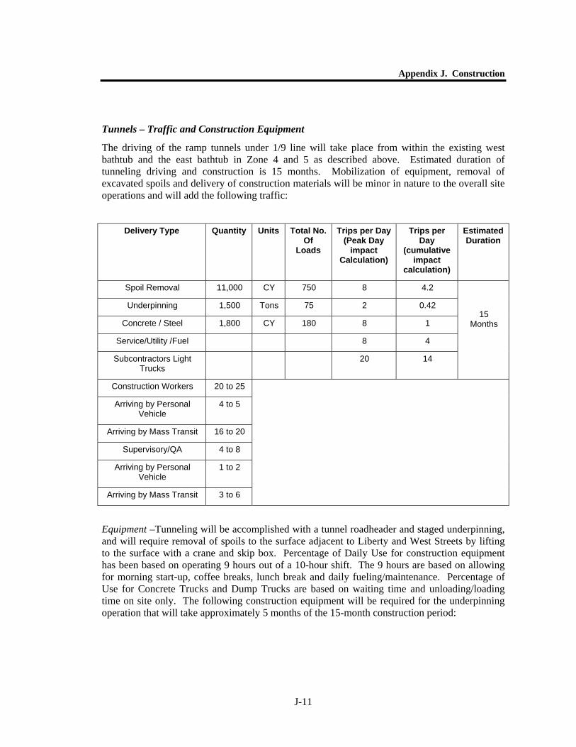
Tunnels – Traffic and Construction Equipment
The driving of the ramp tunnels under 1/9 line will take place from within the existing west bathtub and the east bathtub in Zone 4 and 5 as described above. Estimated duration of tunneling driving and construction is 15 months. Mobilization of equipment, removal of excavated spoils and delivery of construction materials will be minor in nature to the overall site operations and will add the following traffic:
Equipment –Tunneling will be accomplished with a tunnel roadheader and staged underpinning, and will require removal of spoils to the surface adjacent to Liberty and West Streets by lifting to the surface with a crane and skip box. Percentage of Daily Use for construction equipment has been based on operating 9 hours out of a 10-hour shift. The 9 hours are based on allowing for morning start-up, coffee breaks, lunch break and daily fueling/maintenance. Percentage of Use for Concrete Trucks and Dump Trucks are based on waiting time and unloading/loading time on site only. The following construction equipment will be required for the underpinning operation that will take approximately 5 months of the 15-month construction period:
Delivery Type Quantity Units Total No. Of
Loads
Trips per Day (Peak Day
impact Calculation)
Trips per Day
(cumulative impact
calculation)
Estimated Duration
Spoil Removal 11,000 CY 750 8 4.2
Underpinning 1,500 Tons 75 2 0.42
Concrete / Steel 1,800 CY 180 8 1
Service/Utility /Fuel 8 4
Subcontractors Light Trucks
20 14
15 Months
Construction Workers 20 to 25
Arriving by Personal Vehicle
4 to 5
Arriving by Mass Transit 16 to 20
Supervisory/QA 4 to 8
Arriving by Personal Vehicle
1 to 2
Arriving by Mass Transit 3 to 6

World Trade Center Memorial and Redevelopment Plan GEIS
J-12
Equipment Type
Size Engine Type
Size
HP
Quantity (peak
calculation)
Quantity (cumulative calculation)
Percentage Daily Use
Duration
Air Operated Grout Drills
3 1 90%
Hi-Lift (Forklift)
5 ton – 40 foot boom
Diesel 120 2 .67 90%
Concrete Pump
150 CY/Hour – 100 foot
boom
Diesel 300 1 .33 30%
Concrete Trucks
10 Cubic yard Tandem
or Tri-axle
Diesel 325 1 .2 5%
Welding Machines
35 HP Diesel Engine
Diesel 35 4 1.33 90%
15 m
onth
s
The following construction equipment will be required for the excavation of the tunnel and spoil removal operation that will take approximately 5 months of the 15-month construction period:
Equipment Type
Size Engine Type
Size
HP
Quantity (peak
calculation)
Quantity (cumulative calculation)
Percentage Daily Use
Duration
Roadheader for tunneling
12 foot Diameter
Diesel 120 1 .33 33%
Hi-Lift (Forklift) 5 ton – 40 foot boom
Diesel 120 2 .67 90%
Crawler Crane for spoil removal
100 Ton Diesel 350 1 .33 90%
Dump Truck Tandem Axle – 15 CY
Diesel 325 4 2.1 5%
15 m
onth
s
Appendix J. Construction
J-13
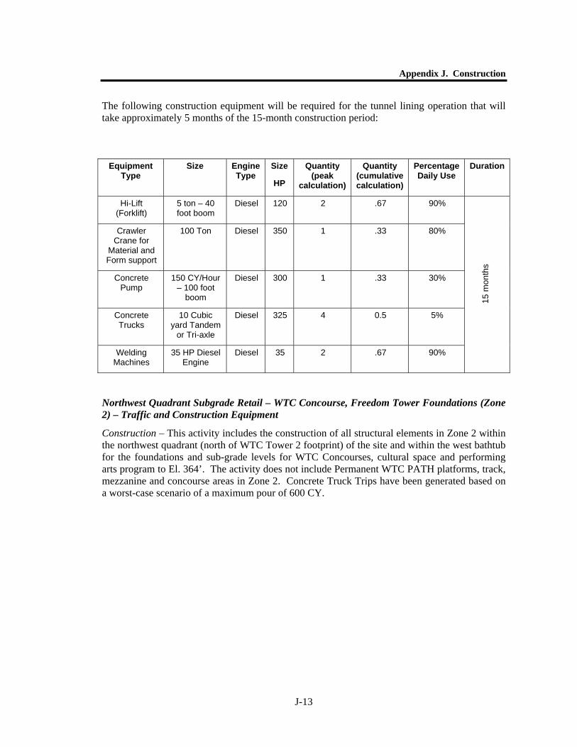
The following construction equipment will be required for the tunnel lining operation that will take approximately 5 months of the 15-month construction period:
Equipment Type
Size Engine Type
Size
HP
Quantity (peak
calculation)
Quantity (cumulative calculation)
Percentage Daily Use
Duration
Hi-Lift (Forklift)
5 ton – 40 foot boom
Diesel 120 2 .67 90%
Crawler Crane for
Material and Form support
100 Ton Diesel 350 1 .33 80%
Concrete Pump
150 CY/Hour – 100 foot
boom
Diesel 300 1 .33 30%
Concrete Trucks
10 Cubic yard Tandem
or Tri-axle
Diesel 325 4 0.5 5%
Welding Machines
35 HP Diesel Engine
Diesel 35 2 .67 90%
15 m
onth
s
Northwest Quadrant Subgrade Retail – WTC Concourse, Freedom Tower Foundations (Zone 2) – Traffic and Construction Equipment
Construction – This activity includes the construction of all structural elements in Zone 2 within the northwest quadrant (north of WTC Tower 2 footprint) of the site and within the west bathtub for the foundations and sub-grade levels for WTC Concourses, cultural space and performing arts program to El. 364’. The activity does not include Permanent WTC PATH platforms, track, mezzanine and concourse areas in Zone 2. Concrete Truck Trips have been generated based on a worst-case scenario of a maximum pour of 600 CY.
World Trade Center Memorial and Redevelopment Plan GEIS
J-14
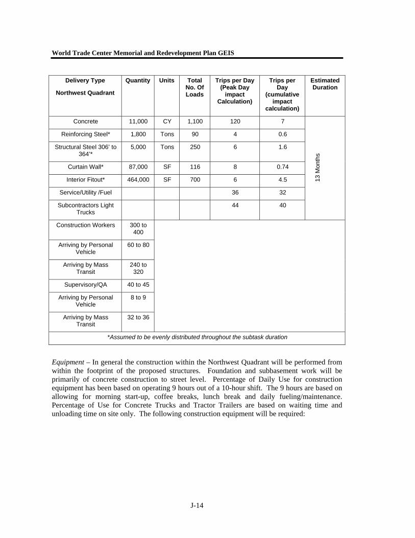
Equipment – In general the construction within the Northwest Quadrant will be performed from within the footprint of the proposed structures. Foundation and subbasement work will be primarily of concrete construction to street level. Percentage of Daily Use for construction equipment has been based on operating 9 hours out of a 10-hour shift. The 9 hours are based on allowing for morning start-up, coffee breaks, lunch break and daily fueling/maintenance. Percentage of Use for Concrete Trucks and Tractor Trailers are based on waiting time and unloading time on site only. The following construction equipment will be required:
Delivery Type
Northwest Quadrant
Quantity Units Total No. Of Loads
Trips per Day (Peak Day
impact Calculation)
Trips per Day
(cumulative impact
calculation)
Estimated Duration
Concrete 11,000 CY 1,100 120 7
Reinforcing Steel* 1,800 Tons 90 4 0.6
Structural Steel 306’ to 364’*
5,000 Tons 250 6 1.6
Curtain Wall* 87,000 SF 116 8 0.74
Interior Fitout* 464,000 SF 700 6 4.5
Service/Utility /Fuel 36 32
Subcontractors Light Trucks
44 40
13 M
onth
s
Construction Workers 300 to 400
Arriving by Personal Vehicle
60 to 80
Arriving by Mass Transit
240 to 320
Supervisory/QA 40 to 45
Arriving by Personal Vehicle
8 to 9
Arriving by Mass Transit
32 to 36
*Assumed to be evenly distributed throughout the subtask duration
Appendix J. Construction
J-15
Equipment Type
Size Engine Type
Size
HP
Quantity (peak
calculation)
Quantity (cumulative calculation)
Percentage Daily Use
Duration
Crawler Crane 200 Ton Diesel 450 2 2 90%
Tower Crane 100 Ton Diesel 250 4 4 90%
Hi-Lift (Forklift) 5 ton – 40 foot boom
Diesel 120 1 1 90%
Concrete Pump
150 CY/Hour – 100 foot boom
Diesel 300 1 1 60%
Concrete Trucks
10 Cubic Yard
Tandem or Tri-Axle
Diesel 325 60 3.5 5%
Diesel Generators
100 HP Diesel 100 4 4 35%
Tractor Trailer Tandem Axle Tractor w/45 Foot
Trailer
Diesel 325 12 3.7 5%
Welding Machines
35 HP Diesel Engine
Diesel 35 4 4 80%
Air Compressor for Impact Wrenches
800 CFM Diesel 310 2 2 80%
Impact Wrenches
1” Socket Drive
16 16 60%
13 m
onth
s
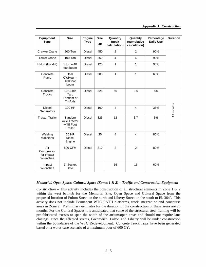
Memorial, Open Space, Cultural Space (Zones 1 & 2) – Traffic and Construction Equipment
Construction – This activity includes the construction of all structural elements in Zone 1 & 2 within the west bathtub for the Memorial Site, Open Space and Cultural Space from the proposed location of Fulton Street on the north and Liberty Street on the south to El. 364’. This activity does not include Permanent WTC PATH platforms, track, mezzanine and concourse areas in Zone 2. Preliminary estimates for the duration of the construction of these areas are 25 months. For the Cultural Spaces it is anticipated that some of the structural steel framing will be pre-fabricated trusses to span the width of the atrium/open areas and should not require lane closings, since the affected streets, Greenwich, Fulton and Liberty will be under construction within the boundaries of the WTC Redevelopment. Concrete Truck Trips have been generated based on a worst-case scenario of a maximum pour of 600 CY.
World Trade Center Memorial and Redevelopment Plan GEIS
J-16
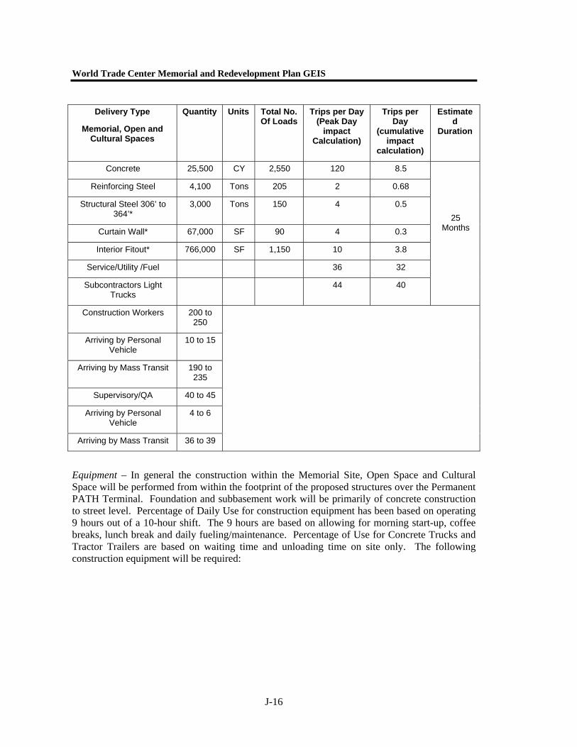
Equipment – In general the construction within the Memorial Site, Open Space and Cultural Space will be performed from within the footprint of the proposed structures over the Permanent PATH Terminal. Foundation and subbasement work will be primarily of concrete construction to street level. Percentage of Daily Use for construction equipment has been based on operating 9 hours out of a 10-hour shift. The 9 hours are based on allowing for morning start-up, coffee breaks, lunch break and daily fueling/maintenance. Percentage of Use for Concrete Trucks and Tractor Trailers are based on waiting time and unloading time on site only. The following construction equipment will be required:
Delivery Type
Memorial, Open and Cultural Spaces
Quantity Units Total No. Of Loads
Trips per Day (Peak Day
impact Calculation)
Trips per Day
(cumulative impact
calculation)
Estimated
Duration
Concrete 25,500 CY 2,550 120 8.5
Reinforcing Steel 4,100 Tons 205 2 0.68
Structural Steel 306’ to 364’*
3,000 Tons 150 4 0.5
Curtain Wall* 67,000 SF 90 4 0.3
Interior Fitout* 766,000 SF 1,150 10 3.8
Service/Utility /Fuel 36 32
Subcontractors Light Trucks
44 40
25 Months
Construction Workers 200 to 250
Arriving by Personal Vehicle
10 to 15
Arriving by Mass Transit 190 to 235
Supervisory/QA 40 to 45
Arriving by Personal Vehicle
4 to 6
Arriving by Mass Transit 36 to 39

Appendix J. Construction
J-17
Equipment Type
Size Engine Type
Size
HP
Quantity (peak
calculation)
Quantity (cumulative calculation)
Percentage Daily Use
Duration
Crawler Crane 200 Ton Diesel 450 1 1 90%
Tower Crane 100 Ton Diesel 250 2 2 90%
Hi-Lift (Forklift) 5 ton – 40 foot boom
Diesel 120 2 2 90%
Concrete Pump
150 CY/Hour – 100 foot boom
Diesel 300 1 1 60%
Concrete Trucks
10 Cubic Yard
Tandem or Tri-Axle
Diesel 325 60 4.2 5%
Diesel Generators
100 HP Diesel 100 4 4 20%
Tractor Trailer Tandem Axle Tractor w/45 Foot
Trailer
Diesel 325 10 2.65 5%
Welding Machines
35 HP Diesel Engine
Diesel 35 4 4 80%
Air Compressor for Impact Wrenches
800 CFM Diesel 310 2 2 80%
Impact Wrenches
1” Socket Drive
16 16 60%
25 m
onth
s
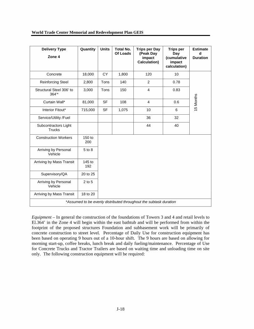
Southeast Quadrant Sub-grade – Towers 3 & 4 Foundations & Retail Below Grade (Zone 4) – Traffic and Construction Equipment
Construction – This activity includes the construction of all structural elements in Zone 4 for the foundations of Towers 3 and 4 and retail areas south of the Permanent PATH Terminal to El. 364’. The activity does not include the Permanent WTC PATH Terminal in Zone 6. Preliminary estimates for the duration of the construction of these areas are 15 months commencing Oct 2005 thru Dec 2006 Concrete Truck Trips have been generated based on a worst-case scenario of a maximum pour of 600 CY.
World Trade Center Memorial and Redevelopment Plan GEIS
J-18
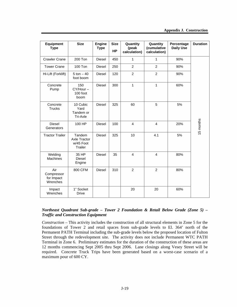
Equipment – In general the construction of the foundations of Towers 3 and 4 and retail levels to El.364’ in the Zone 4 will begin within the east bathtub and will be performed from within the footprint of the proposed structures Foundation and subbasement work will be primarily of concrete construction to street level. Percentage of Daily Use for construction equipment has been based on operating 9 hours out of a 10-hour shift. The 9 hours are based on allowing for morning start-up, coffee breaks, lunch break and daily fueling/maintenance. Percentage of Use for Concrete Trucks and Tractor Trailers are based on waiting time and unloading time on site only. The following construction equipment will be required:
Delivery Type
Zone 4
Quantity Units Total No. Of Loads
Trips per Day (Peak Day
impact Calculation)
Trips per Day
(cumulative impact
calculation)
Estimated
Duration
Concrete 18,000 CY 1,800 120 10
Reinforcing Steel 2,800 Tons 140 2 0.78
Structural Steel 306’ to 364’*
3,000 Tons 150 4 0.83
Curtain Wall* 81,000 SF 108 4 0.6
Interior Fitout* 715,000 SF 1,075 10 6
Service/Utility /Fuel 36 32
Subcontractors Light Trucks
44 40
15 M
onth
s
Construction Workers 150 to 200
Arriving by Personal Vehicle
5 to 8
Arriving by Mass Transit 145 to 192
Supervisory/QA 20 to 25
Arriving by Personal Vehicle
2 to 5
Arriving by Mass Transit 18 to 20
*Assumed to be evenly distributed throughout the subtask duration
Appendix J. Construction
J-19
Equipment Type
Size Engine Type
Size
HP
Quantity (peak
calculation)
Quantity (cumulative calculation)
Percentage Daily Use
Duration
Crawler Crane 200 Ton Diesel 450 1 1 90%
Tower Crane 100 Ton Diesel 250 2 2 90%
Hi-Lift (Forklift) 5 ton – 40 foot boom
Diesel 120 2 2 90%
Concrete Pump
150 CY/Hour – 100 foot boom
Diesel 300 1 1 60%
Concrete Trucks
10 Cubic Yard
Tandem or Tri-Axle
Diesel 325 60 5 5%
Diesel Generators
100 HP Diesel 100 4 4 20%
Tractor Trailer Tandem Axle Tractor w/45 Foot
Trailer
Diesel 325 10 4.1 5%
Welding Machines
35 HP Diesel Engine
Diesel 35 4 4 80%
Air Compressor for Impact Wrenches
800 CFM Diesel 310 2 2 80%
Impact Wrenches
1” Socket Drive
20 20 60%
15 m
onth
s
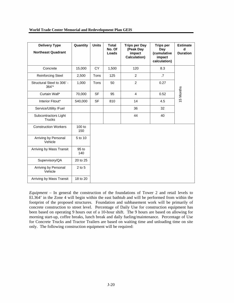
Northeast Quadrant Sub-grade – Tower 2 Foundation & Retail Below Grade (Zone 5) – Traffic and Construction Equipment
Construction – This activity includes the construction of all structural elements in Zone 5 for the foundations of Tower 2 and retail spaces from sub-grade levels to El. 364’ north of the Permanent PATH Terminal including the sub-grade levels below the proposed location of Fulton Street through the redevelopment site. The activity does not include Permanent WTC PATH Terminal in Zone 6. Preliminary estimates for the duration of the construction of these areas are 12 months commencing Sept 2005 thru Sept 2006. Lane closings along Vesey Street will be required. Concrete Truck Trips have been generated based on a worst-case scenario of a maximum pour of 600 CY.
World Trade Center Memorial and Redevelopment Plan GEIS
J-20
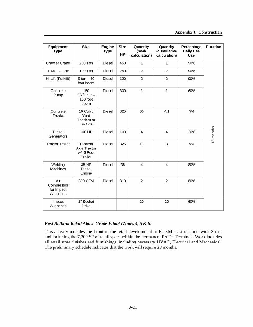
Equipment – In general the construction of the foundations of Tower 2 and retail levels to El.364’ in the Zone 4 will begin within the east bathtub and will be performed from within the footprint of the proposed structures. Foundation and subbasement work will be primarily of concrete construction to street level. Percentage of Daily Use for construction equipment has been based on operating 9 hours out of a 10-hour shift. The 9 hours are based on allowing for morning start-up, coffee breaks, lunch break and daily fueling/maintenance. Percentage of Use for Concrete Trucks and Tractor Trailers are based on waiting time and unloading time on site only. The following construction equipment will be required:
Delivery Type
Northeast Quadrant
Quantity Units Total No. Of Loads
Trips per Day (Peak Day
impact Calculation)
Trips per Day
(cumulative impact
calculation)
Estimated
Duration
Concrete 15,000 CY 1,500 120 8.3
Reinforcing Steel 2,500 Tons 125 2 .7
Structural Steel to 306’ - 364’*
1,000 Tons 50 2 0.27
Curtain Wall* 70,000 SF 95 4 0.52
Interior Fitout* 540,000 SF 810 14 4.5
Service/Utility /Fuel 36 32
Subcontractors Light Trucks
44 40
15 M
onth
s
Construction Workers 100 to 150
Arriving by Personal Vehicle
5 to 10
Arriving by Mass Transit 95 to 140
Supervisory/QA 20 to 25
Arriving by Personal Vehicle
2 to 5
Arriving by Mass Transit 18 to 20
Appendix J. Construction
J-21
Equipment Type
Size Engine Type
Size
HP
Quantity (peak
calculation)
Quantity (cumulative calculation)
Percentage Daily Use
Use
Duration
Crawler Crane 200 Ton Diesel 450 1 1 90%
Tower Crane 100 Ton Diesel 250 2 2 90%
Hi-Lift (Forklift) 5 ton – 40 foot boom
Diesel 120 2 2 90%
Concrete Pump
150 CY/Hour – 100 foot boom
Diesel 300 1 1 60%
Concrete Trucks
10 Cubic Yard
Tandem or Tri-Axle
Diesel 325 60 4.1 5%
Diesel Generators
100 HP Diesel 100 4 4 20%
Tractor Trailer Tandem Axle Tractor w/45 Foot
Trailer
Diesel 325 11 3 5%
Welding Machines
35 HP Diesel Engine
Diesel 35 4 4 80%
Air Compressor for Impact Wrenches
800 CFM Diesel 310 2 2 80%
Impact Wrenches
1” Socket Drive
20 20 60%
15 m
onth
s
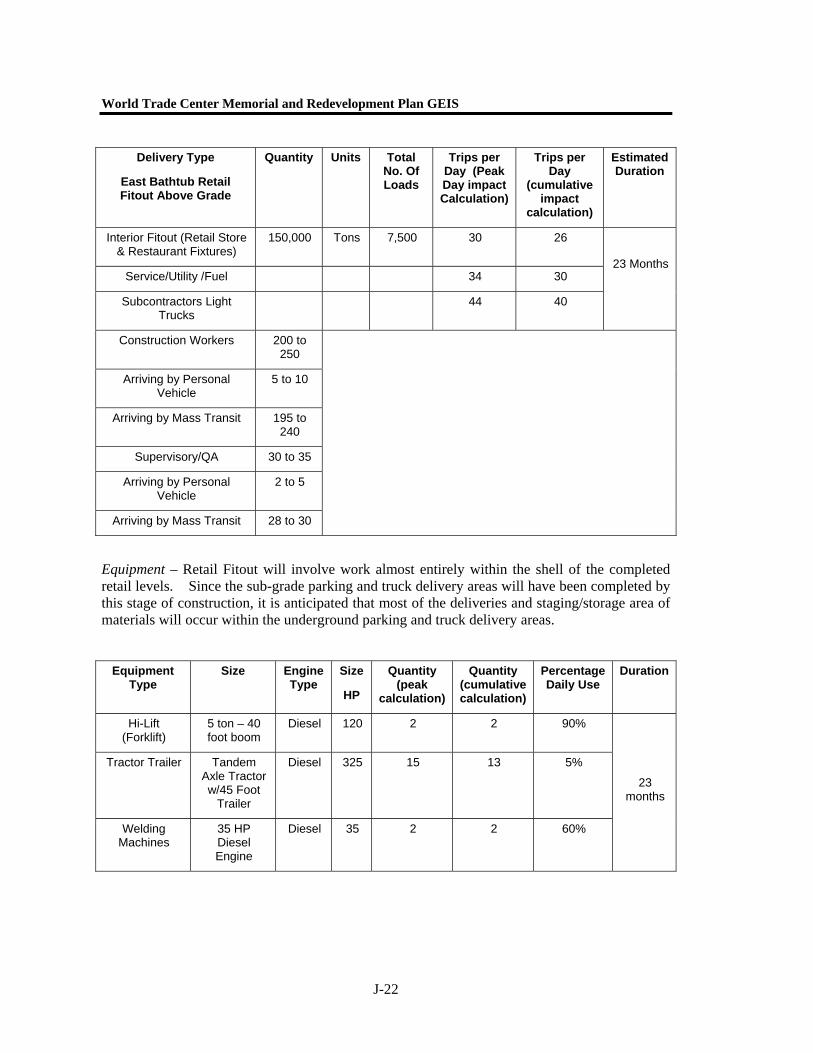
East Bathtub Retail Above Grade Fitout (Zones 4, 5 & 6)
This activity includes the fitout of the retail development to El. 364’ east of Greenwich Street and including the 7,200 SF of retail space within the Permanent PATH Terminal. Work includes all retail store finishes and furnishings, including necessary HVAC, Electrical and Mechanical. The preliminary schedule indicates that the work will require 23 months.
World Trade Center Memorial and Redevelopment Plan GEIS
J-22
Equipment – Retail Fitout will involve work almost entirely within the shell of the completed retail levels. Since the sub-grade parking and truck delivery areas will have been completed by this stage of construction, it is anticipated that most of the deliveries and staging/storage area of materials will occur within the underground parking and truck delivery areas.
Equipment Type
Size Engine Type
Size
HP
Quantity (peak
calculation)
Quantity (cumulative calculation)
Percentage Daily Use
Duration
Hi-Lift (Forklift)
5 ton – 40 foot boom
Diesel 120 2 2 90%
Tractor Trailer Tandem Axle Tractor w/45 Foot
Trailer
Diesel 325 15 13 5%
Welding Machines
35 HP Diesel Engine
Diesel 35 2 2 60%
23 months
Delivery Type
East Bathtub Retail Fitout Above Grade
Quantity Units Total No. Of Loads
Trips per Day (Peak Day impact Calculation)
Trips per Day
(cumulative impact
calculation)
Estimated Duration
Interior Fitout (Retail Store & Restaurant Fixtures)
150,000 Tons 7,500 30 26
Service/Utility /Fuel 34 30
Subcontractors Light Trucks
44 40
23 Months
Construction Workers 200 to 250
Arriving by Personal Vehicle
5 to 10
Arriving by Mass Transit 195 to 240
Supervisory/QA 30 to 35
Arriving by Personal Vehicle
2 to 5
Arriving by Mass Transit 28 to 30
Appendix J. Construction
J-23
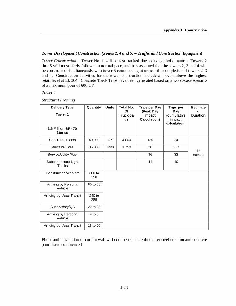
Tower Development Construction (Zones 2, 4 and 5) – Traffic and Construction Equipment
Tower Construction – Tower No. 1 will be fast tracked due to its symbolic nature. Towers 2 thru 5 will most likely follow at a normal pace, and it is assumed that the towers 2, 3 and 4 will be constructed simultaneously with tower 5 commencing at or near the completion of towers 2, 3 and 4. Construction activities for the tower construction include all levels above the highest retail level at El. 364. Concrete Truck Trips have been generated based on a worst-case scenario of a maximum pour of 600 CY.
Tower 1
Structural Framing
Fitout and installation of curtain wall will commence some time after steel erection and concrete pours have commenced
Delivery Type
Tower 1
2.6 Million SF - 70 Stories
Quantity Units Total No. Of
Truckloads
Trips per Day (Peak Day
impact Calculation)
Trips per Day
(cumulative impact
calculation)
Estimated
Duration
Concrete - Floors 40,000 CY 4,000 120 24
Structural Steel 35,000 Tons 1,750 20 10.4
Service/Utility /Fuel 36 32
Subcontractors Light Trucks
44 40
14 months
Construction Workers 300 to 350
Arriving by Personal Vehicle
60 to 65
Arriving by Mass Transit 240 to 285
Supervisory/QA 20 to 25
Arriving by Personal Vehicle
4 to 5
Arriving by Mass Transit 16 to 20
World Trade Center Memorial and Redevelopment Plan GEIS
J-24
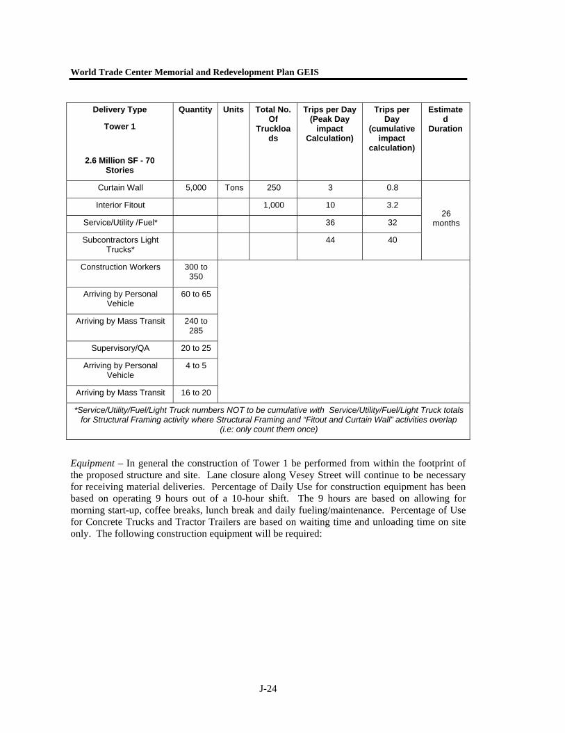
Equipment – In general the construction of Tower 1 be performed from within the footprint of the proposed structure and site. Lane closure along Vesey Street will continue to be necessary for receiving material deliveries. Percentage of Daily Use for construction equipment has been based on operating 9 hours out of a 10-hour shift. The 9 hours are based on allowing for morning start-up, coffee breaks, lunch break and daily fueling/maintenance. Percentage of Use for Concrete Trucks and Tractor Trailers are based on waiting time and unloading time on site only. The following construction equipment will be required:
Delivery Type
Tower 1
2.6 Million SF - 70 Stories
Quantity Units Total No. Of
Truckloads
Trips per Day (Peak Day
impact Calculation)
Trips per Day
(cumulative impact
calculation)
Estimated
Duration
Curtain Wall 5,000 Tons 250 3 0.8
Interior Fitout 1,000 10 3.2
Service/Utility /Fuel* 36 32
Subcontractors Light Trucks*
44 40
26 months
Construction Workers 300 to 350
Arriving by Personal Vehicle
60 to 65
Arriving by Mass Transit 240 to 285
Supervisory/QA 20 to 25
Arriving by Personal Vehicle
4 to 5
Arriving by Mass Transit 16 to 20
*Service/Utility/Fuel/Light Truck numbers NOT to be cumulative with Service/Utility/Fuel/Light Truck totals for Structural Framing activity where Structural Framing and “Fitout and Curtain Wall” activities overlap
(i.e: only count them once)
Appendix J. Construction
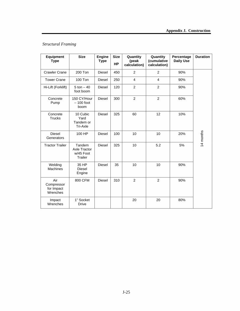
J-25
Structural Framing
Equipment Type
Size Engine Type
Size
HP
Quantity (peak
calculation)
Quantity (cumulative calculation)
Percentage Daily Use
Duration
Crawler Crane 200 Ton Diesel 450 2 2 90%
Tower Crane 100 Ton Diesel 250 4 4 90%
Hi-Lift (Forklift) 5 ton – 40 foot boom
Diesel 120 2 2 90%
Concrete Pump
150 CY/Hour – 100 foot
boom
Diesel 300 2 2 60%
Concrete Trucks
10 Cubic Yard
Tandem or Tri-Axle
Diesel 325 60 12 10%
Diesel Generators
100 HP Diesel 100 10 10 20%
Tractor Trailer Tandem Axle Tractor w/45 Foot
Trailer
Diesel 325 10 5.2 5%
Welding Machines
35 HP Diesel Engine
Diesel 35 10 10 90%
Air Compressor for Impact Wrenches
800 CFM Diesel 310 2 2 90%
Impact Wrenches
1” Socket Drive
20 20 80% 14
mon
ths
World Trade Center Memorial and Redevelopment Plan GEIS
J-26
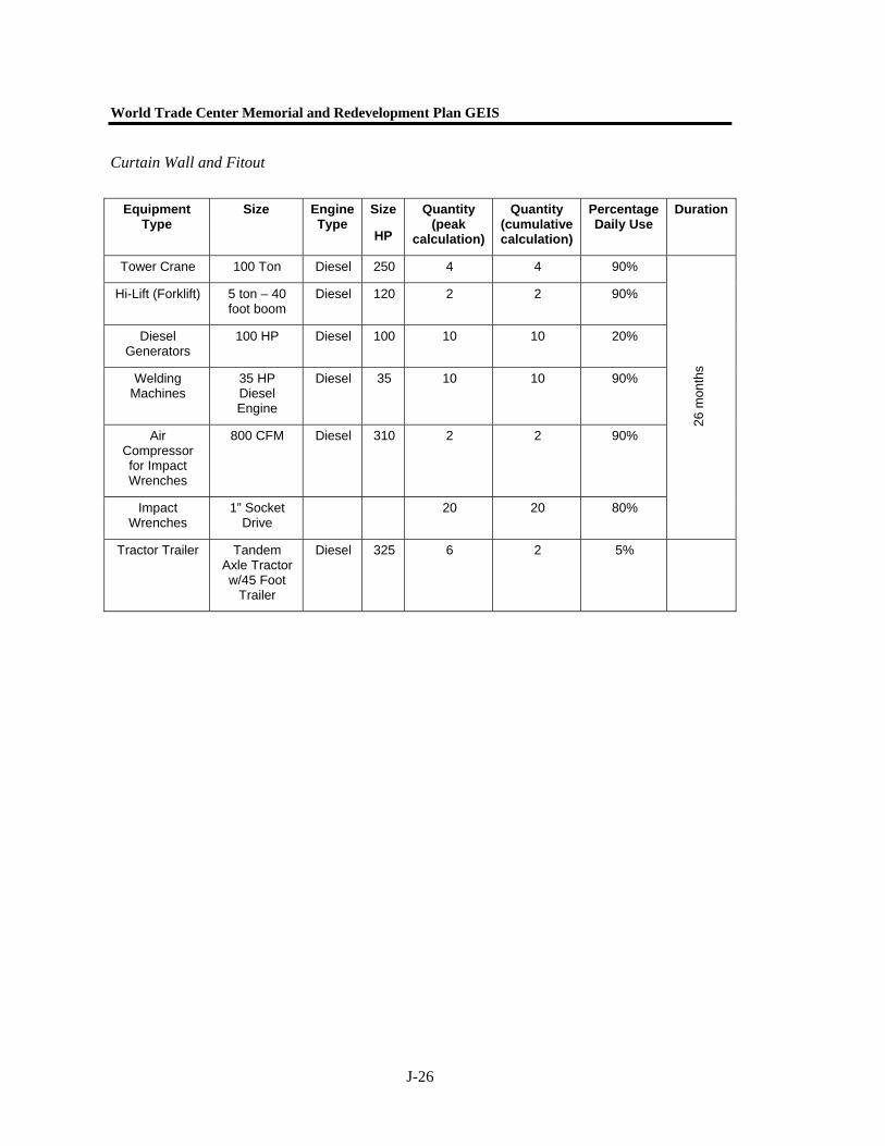
Curtain Wall and Fitout
Equipment Type
Size Engine Type
Size
HP
Quantity (peak
calculation)
Quantity (cumulative calculation)
Percentage Daily Use
Duration
Tower Crane 100 Ton Diesel 250 4 4 90%
Hi-Lift (Forklift) 5 ton – 40 foot boom
Diesel 120 2 2 90%
Diesel Generators
100 HP Diesel 100 10 10 20%
Welding Machines
35 HP Diesel Engine
Diesel 35 10 10 90%
Air Compressor for Impact Wrenches
800 CFM Diesel 310 2 2 90%
Impact Wrenches
1” Socket Drive
20 20 80%
26 m
onth
s
Tractor Trailer Tandem Axle Tractor w/45 Foot
Trailer
Diesel 325 6 2 5%

Appendix J. Construction
J-27
Towers 2, 3, and 4
Structural Framing
Delivery Type
Towers 2, 3 & 4
2.05 Million SF – 65 Stories
2.0 Million SF - 60 Stories
1.73 Million SF – 55 Stories
Quantity Units Total No. Of
Truckloads
Trips per Day (Peak Day
impact Calculation)
Trips per Day
(cumulative impact
calculation)
Estimated Duration
Concrete 90,000 CY 9,000 100 31.3
Structural Steel 84,000 Tons 4,200 26 14.5
Service/Utility /Fuel 26 22
Subcontractors Light Trucks
44 40 24 M
onth
s
Construction Workers 700 to 900
Arriving by Personal Vehicle
50 to 60
Arriving by Mass Transit 650 to 840
Supervisory/QA 60 to 75
Arriving by Personal Vehicle
4 to 5
Arriving by Mass Transit 56 to 70
World Trade Center Memorial and Redevelopment Plan GEIS
J-28
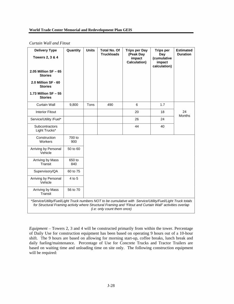
Curtain Wall and Fitout
Equipment – Towers 2, 3 and 4 will be constructed primarily from within the tower. Percentage of Daily Use for construction equipment has been based on operating 9 hours out of a 10-hour shift. The 9 hours are based on allowing for morning start-up, coffee breaks, lunch break and daily fueling/maintenance. Percentage of Use for Concrete Trucks and Tractor Trailers are based on waiting time and unloading time on site only. The following construction equipment will be required:
Delivery Type
Towers 2, 3 & 4
2.05 Million SF – 65 Stories
2.0 Million SF - 60 Stories
1.73 Million SF – 55 Stories
Quantity Units Total No. Of Truckloads
Trips per Day (Peak Day
impact Calculation)
Trips per Day
(cumulative impact
calculation)
Estimated Duration
Curtain Wall 9,800 Tons 490 6 1.7
Interior Fitout 20 18
Service/Utility /Fuel* 26 24
Subcontractors Light Trucks*
44 40
24 Months
Construction Workers
700 to 900
Arriving by Personal Vehicle
50 to 60
Arriving by Mass Transit
650 to 840
Supervisory/QA 60 to 75
Arriving by Personal Vehicle
4 to 5
Arriving by Mass Transit
56 to 70
*Service/Utility/Fuel/Light Truck numbers NOT to be cumulative with Service/Utility/Fuel/Light Truck totals for Structural Framing activity where Structural Framing and “Fitout and Curtain Wall” activities overlap
(i.e: only count them once)

Appendix J. Construction
J-29
Structural Framing
Equipment Type
Size Engine Type
Size
HP
Quantity (peak
calculation)
Quantity (cumulative calculation)
Percentage Daily Use
Duration
Crawler Crane 200 Ton Diesel 450 4 4 90%
Tower Crane 100 Ton Diesel 250 6 6 90%
Hi-Lift (Forklift) 5 ton – 40 foot boom
Diesel 120 3 3 90%
Concrete Pump
150 CY/Hour – 100 foot
boom
Diesel 300 4 4 60%
Concrete Trucks
10 Cubic Yard
Tandem or Tri-Axle
Diesel 325 50 15 5%
Diesel Generators
100 HP Diesel 100 16 16 20%
Tractor Trailer Tandem Axle Tractor w/45 Foot Trailer
Diesel 325 13 7 5%
Welding Machines
35 HP Diesel Engine
Diesel 35 6 6 90%
Air Compressor for Impact Wrenches
800 CFM Diesel 310 3 3 90%
Impact Wrenches
1” Socket Drive
60 60 80%
24 m
onth
s
World Trade Center Memorial and Redevelopment Plan GEIS
J-30
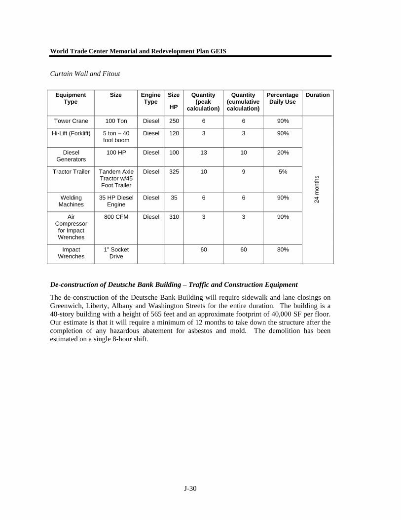
Curtain Wall and Fitout
Equipment Type
Size Engine Type
Size
HP
Quantity (peak
calculation)
Quantity (cumulative calculation)
Percentage Daily Use
Duration
Tower Crane 100 Ton Diesel 250 6 6 90%
Hi-Lift (Forklift) 5 ton – 40 foot boom
Diesel 120 3 3 90%
Diesel Generators
100 HP Diesel 100 13 10 20%
Tractor Trailer Tandem Axle Tractor w/45 Foot Trailer
Diesel 325 10 9 5%
Welding Machines
35 HP Diesel Engine
Diesel 35 6 6 90%
Air Compressor for Impact Wrenches
800 CFM Diesel 310 3 3 90%
Impact Wrenches
1” Socket Drive
60 60 80%
24 m
onth
s
De-construction of Deutsche Bank Building – Traffic and Construction Equipment
The de-construction of the Deutsche Bank Building will require sidewalk and lane closings on Greenwich, Liberty, Albany and Washington Streets for the entire duration. The building is a 40-story building with a height of 565 feet and an approximate footprint of 40,000 SF per floor. Our estimate is that it will require a minimum of 12 months to take down the structure after the completion of any hazardous abatement for asbestos and mold. The demolition has been estimated on a single 8-hour shift.
Appendix J. Construction
J-31
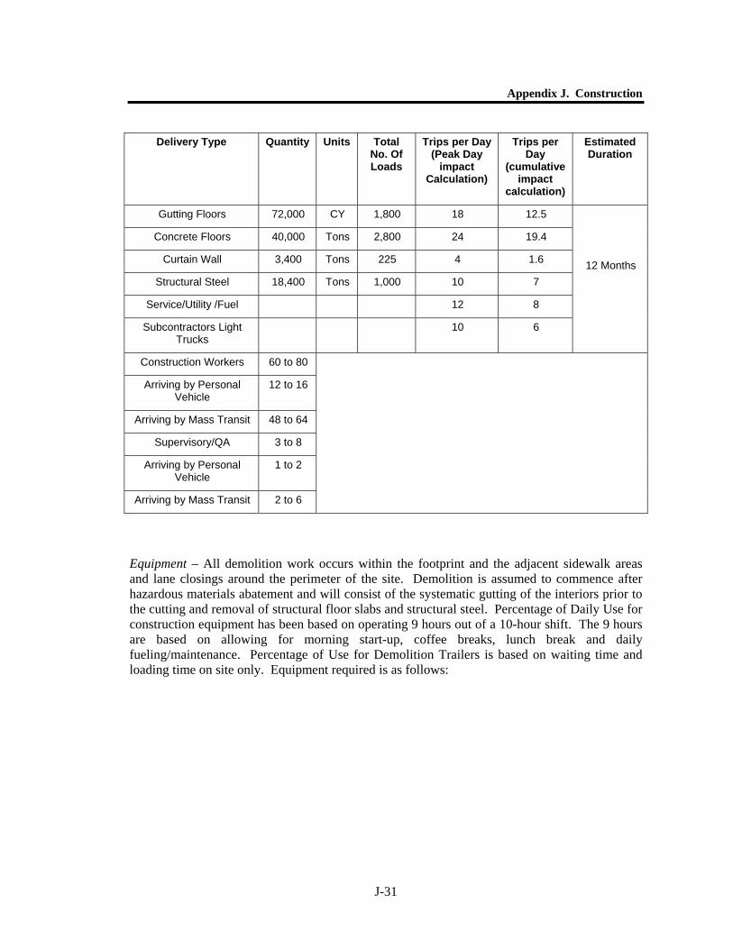
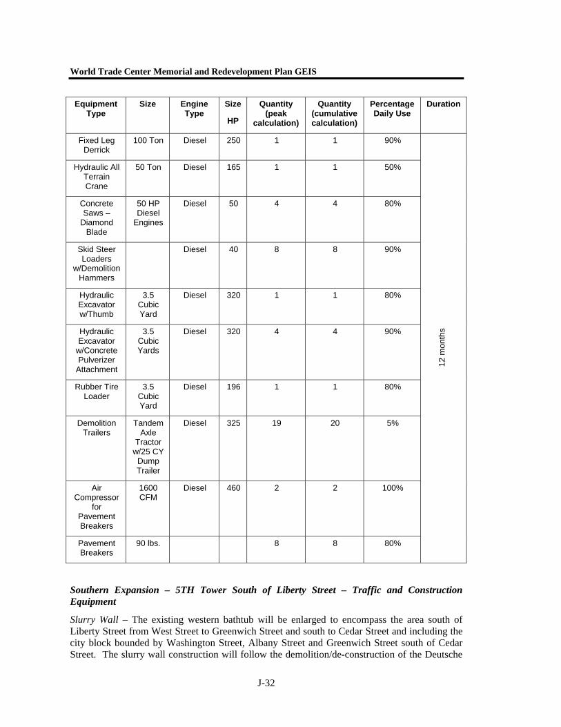
Equipment – All demolition work occurs within the footprint and the adjacent sidewalk areas and lane closings around the perimeter of the site. Demolition is assumed to commence after hazardous materials abatement and will consist of the systematic gutting of the interiors prior to the cutting and removal of structural floor slabs and structural steel. Percentage of Daily Use for construction equipment has been based on operating 9 hours out of a 10-hour shift. The 9 hours are based on allowing for morning start-up, coffee breaks, lunch break and daily fueling/maintenance. Percentage of Use for Demolition Trailers is based on waiting time and loading time on site only. Equipment required is as follows:
Delivery Type Quantity Units Total No. Of Loads
Trips per Day (Peak Day
impact Calculation)
Trips per Day
(cumulative impact
calculation)
Estimated Duration
Gutting Floors 72,000 CY 1,800 18 12.5
Concrete Floors 40,000 Tons 2,800 24 19.4
Curtain Wall 3,400 Tons 225 4 1.6
Structural Steel 18,400 Tons 1,000 10 7
Service/Utility /Fuel 12 8
Subcontractors Light Trucks
10 6
12 Months
Construction Workers 60 to 80
Arriving by Personal Vehicle
12 to 16
Arriving by Mass Transit 48 to 64
Supervisory/QA 3 to 8
Arriving by Personal Vehicle
1 to 2
Arriving by Mass Transit 2 to 6
World Trade Center Memorial and Redevelopment Plan GEIS
J-32
Equipment Type
Size Engine Type
Size
HP
Quantity (peak
calculation)
Quantity (cumulative calculation)
Percentage Daily Use
Duration
Fixed Leg Derrick
100 Ton Diesel 250 1 1 90%
Hydraulic All Terrain Crane
50 Ton Diesel 165 1 1 50%
Concrete Saws –
Diamond Blade
50 HP Diesel
Engines
Diesel 50 4 4 80%
Skid Steer Loaders
w/Demolition Hammers
Diesel 40 8 8 90%
Hydraulic Excavator w/Thumb
3.5 Cubic Yard
Diesel 320 1 1 80%
Hydraulic Excavator
w/Concrete Pulverizer
Attachment
3.5 Cubic Yards
Diesel 320 4 4 90%
Rubber Tire Loader
3.5 Cubic Yard
Diesel 196 1 1 80%
Demolition Trailers
Tandem Axle
Tractor w/25 CY Dump Trailer
Diesel 325 19 20 5%
Air Compressor
for Pavement Breakers
1600 CFM
Diesel 460 2 2 100%
Pavement Breakers
90 lbs. 8 8 80%
12 m
onth
s
Southern Expansion – 5TH Tower South of Liberty Street – Traffic and Construction Equipment
Slurry Wall – The existing western bathtub will be enlarged to encompass the area south of Liberty Street from West Street to Greenwich Street and south to Cedar Street and including the city block bounded by Washington Street, Albany Street and Greenwich Street south of Cedar Street. The slurry wall construction will follow the demolition/de-construction of the Deutsche
Appendix J. Construction
J-33
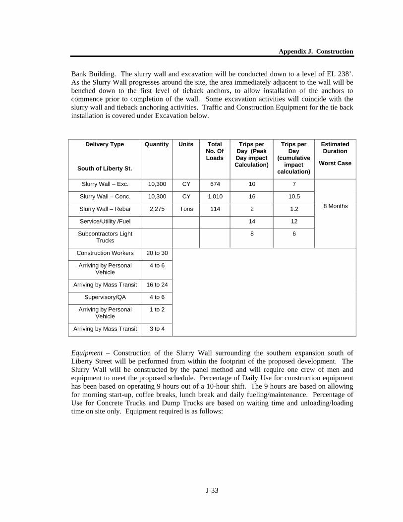
Bank Building. The slurry wall and excavation will be conducted down to a level of EL 238’. As the Slurry Wall progresses around the site, the area immediately adjacent to the wall will be benched down to the first level of tieback anchors, to allow installation of the anchors to commence prior to completion of the wall. Some excavation activities will coincide with the slurry wall and tieback anchoring activities. Traffic and Construction Equipment for the tie back installation is covered under Excavation below.
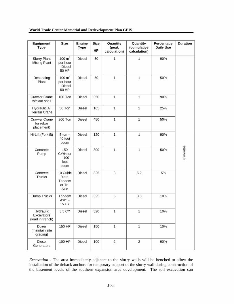
Equipment – Construction of the Slurry Wall surrounding the southern expansion south of Liberty Street will be performed from within the footprint of the proposed development. The Slurry Wall will be constructed by the panel method and will require one crew of men and equipment to meet the proposed schedule. Percentage of Daily Use for construction equipment has been based on operating 9 hours out of a 10-hour shift. The 9 hours are based on allowing for morning start-up, coffee breaks, lunch break and daily fueling/maintenance. Percentage of Use for Concrete Trucks and Dump Trucks are based on waiting time and unloading/loading time on site only. Equipment required is as follows:
Delivery Type
South of Liberty St.
Quantity Units Total No. Of Loads
Trips per Day (Peak Day impact Calculation)
Trips per Day
(cumulative impact
calculation)
Estimated Duration
Worst Case
Slurry Wall – Exc. 10,300 CY 674 10 7
Slurry Wall – Conc. 10,300 CY 1,010 16 10.5
Slurry Wall – Rebar 2,275 Tons 114 2 1.2
Service/Utility /Fuel 14 12
Subcontractors Light Trucks
8 6
8 Months
Construction Workers 20 to 30
Arriving by Personal Vehicle
4 to 6
Arriving by Mass Transit 16 to 24
Supervisory/QA 4 to 6
Arriving by Personal Vehicle
1 to 2
Arriving by Mass Transit 3 to 4
World Trade Center Memorial and Redevelopment Plan GEIS
J-34
Equipment Type
Size Engine Type
Size
HP
Quantity (peak
calculation)
Quantity (cumulative calculation)
Percentage Daily Use
Duration
Slurry Plant Mixing Plant
100 m3 per hour – Diesel 50 HP
Diesel 50 1 1 90%
Desanding Plant
100 m3 per hour – Diesel 50 HP
Diesel 50 1 1 50%
Crawler Crane w/clam shell
100 Ton Diesel 350 1 1 90%
Hydraulic All Terrain Crane
50 Ton Diesel 165 1 1 25%
Crawler Crane for rebar
placement)
200 Ton Diesel 450 1 1 50%
Hi-Lift (Forklift) 5 ton – 40 foot boom
Diesel 120 1 1 90%
Concrete Pump
150 CY/Hour
– 100 foot
boom
Diesel 300 1 1 50%
Concrete Trucks
10 Cubic Yard
Tandem or Tri-Axle
Diesel 325 8 5.2 5%
Dump Trucks Tandem Axle – 15 CY
Diesel 325 5 3.5 10%
Hydraulic Excavators
(lead in trench)
3.5 CY Diesel 320 1 1 10%
Dozer (maintain site
grading)
150 HP Diesel 150 1 1 10%
Diesel Generators
100 HP Diesel 100 2 2 90%
8 m
onth
s
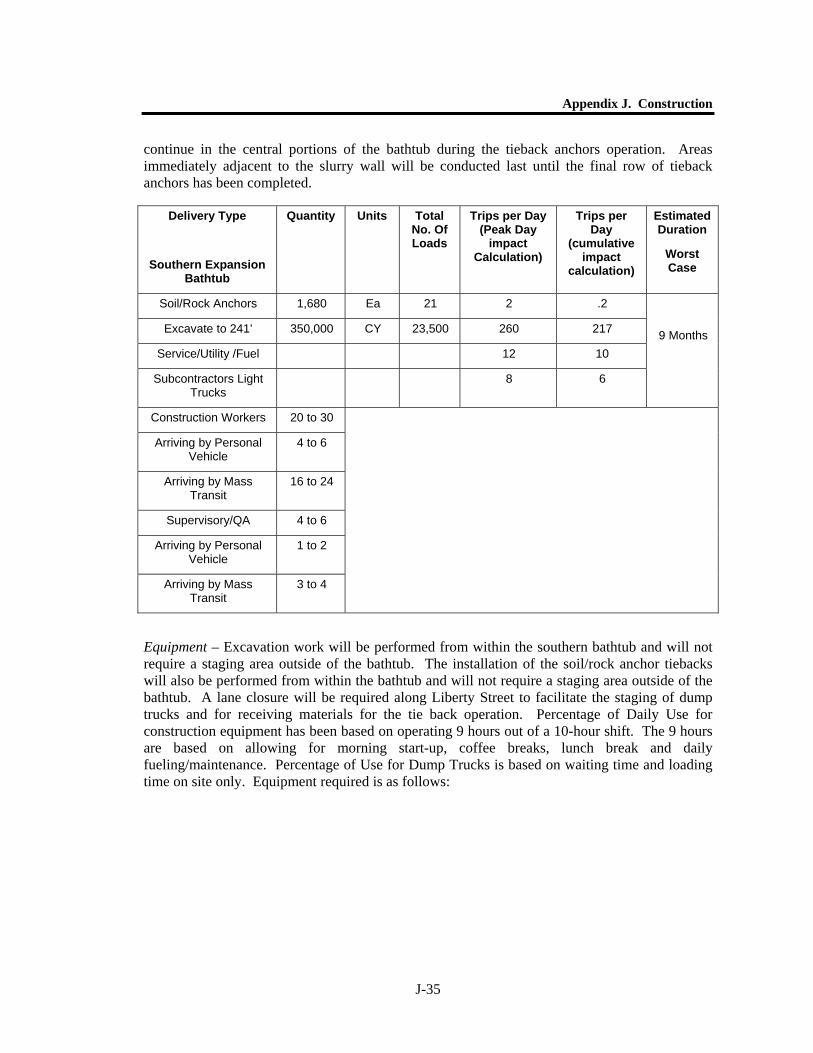
Excavation - The area immediately adjacent to the slurry walls will be benched to allow the installation of the tieback anchors for temporary support of the slurry wall during construction of the basement levels of the southern expansion area development. The soil excavation can
Appendix J. Construction
J-35
continue in the central portions of the bathtub during the tieback anchors operation. Areas immediately adjacent to the slurry wall will be conducted last until the final row of tieback anchors has been completed.
Equipment – Excavation work will be performed from within the southern bathtub and will not require a staging area outside of the bathtub. The installation of the soil/rock anchor tiebacks will also be performed from within the bathtub and will not require a staging area outside of the bathtub. A lane closure will be required along Liberty Street to facilitate the staging of dump trucks and for receiving materials for the tie back operation. Percentage of Daily Use for construction equipment has been based on operating 9 hours out of a 10-hour shift. The 9 hours are based on allowing for morning start-up, coffee breaks, lunch break and daily fueling/maintenance. Percentage of Use for Dump Trucks is based on waiting time and loading time on site only. Equipment required is as follows:
Delivery Type
Southern Expansion Bathtub
Quantity Units Total No. Of Loads
Trips per Day (Peak Day
impact Calculation)
Trips per Day
(cumulative impact
calculation)
Estimated Duration
Worst Case
Soil/Rock Anchors 1,680 Ea 21 2 .2
Excavate to 241’ 350,000 CY 23,500 260 217
Service/Utility /Fuel 12 10
Subcontractors Light Trucks
8 6
9 Months
Construction Workers 20 to 30
Arriving by Personal Vehicle
4 to 6
Arriving by Mass Transit
16 to 24
Supervisory/QA 4 to 6
Arriving by Personal Vehicle
1 to 2
Arriving by Mass Transit
3 to 4
World Trade Center Memorial and Redevelopment Plan GEIS
J-36
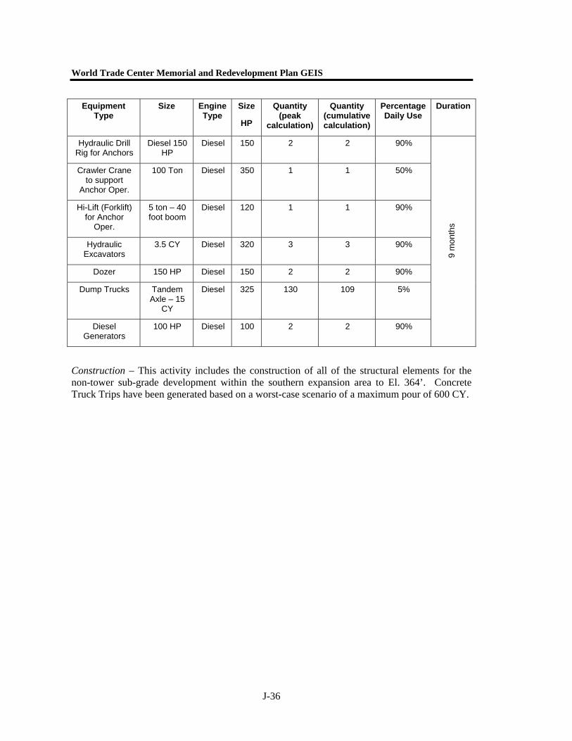
Equipment Type
Size Engine Type
Size
HP
Quantity (peak
calculation)
Quantity (cumulative calculation)
Percentage Daily Use
Duration
Hydraulic Drill Rig for Anchors
Diesel 150 HP
Diesel 150 2 2 90%
Crawler Crane to support
Anchor Oper.
100 Ton Diesel 350 1 1 50%
Hi-Lift (Forklift) for Anchor
Oper.
5 ton – 40 foot boom
Diesel 120 1 1 90%
Hydraulic Excavators
3.5 CY Diesel 320 3 3 90%
Dozer 150 HP Diesel 150 2 2 90%
Dump Trucks Tandem Axle – 15
CY
Diesel 325 130 109 5%
Diesel Generators
100 HP Diesel 100 2 2 90%
9 m
onth
s
Construction – This activity includes the construction of all of the structural elements for the non-tower sub-grade development within the southern expansion area to El. 364’. Concrete Truck Trips have been generated based on a worst-case scenario of a maximum pour of 600 CY.
Appendix J. Construction
J-37
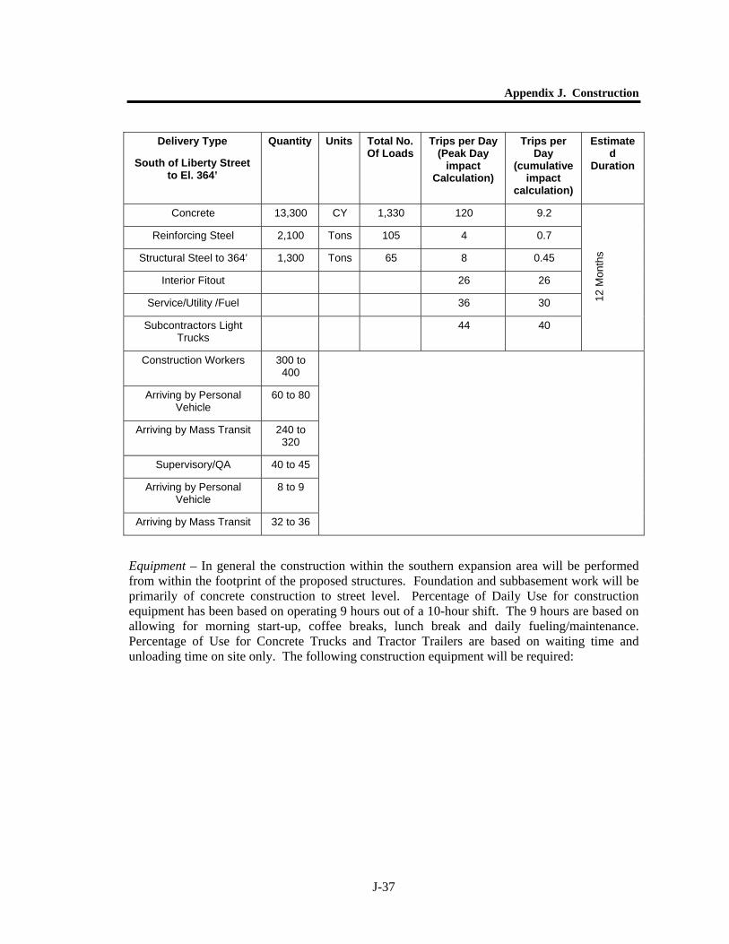
Equipment – In general the construction within the southern expansion area will be performed from within the footprint of the proposed structures. Foundation and subbasement work will be primarily of concrete construction to street level. Percentage of Daily Use for construction equipment has been based on operating 9 hours out of a 10-hour shift. The 9 hours are based on allowing for morning start-up, coffee breaks, lunch break and daily fueling/maintenance. Percentage of Use for Concrete Trucks and Tractor Trailers are based on waiting time and unloading time on site only. The following construction equipment will be required:
Delivery Type
South of Liberty Street to El. 364’
Quantity Units Total No. Of Loads
Trips per Day (Peak Day
impact Calculation)
Trips per Day
(cumulative impact
calculation)
Estimated
Duration
Concrete 13,300 CY 1,330 120 9.2
Reinforcing Steel 2,100 Tons 105 4 0.7
Structural Steel to 364’ 1,300 Tons 65 8 0.45
Interior Fitout 26 26
Service/Utility /Fuel 36 30
Subcontractors Light Trucks
44 40
12 M
onth
s
Construction Workers 300 to 400
Arriving by Personal Vehicle
60 to 80
Arriving by Mass Transit 240 to 320
Supervisory/QA 40 to 45
Arriving by Personal Vehicle
8 to 9
Arriving by Mass Transit 32 to 36
World Trade Center Memorial and Redevelopment Plan GEIS
J-38
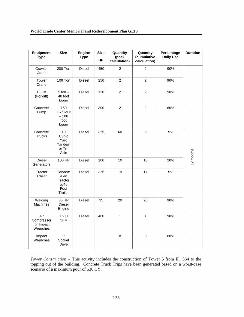
Equipment Type
Size Engine Type
Size
HP
Quantity (peak
calculation)
Quantity (cumulative calculation)
Percentage Daily Use
Duration
Crawler Crane
200 Ton Diesel 450 2 2 90%
Tower Crane
100 Ton Diesel 250 2 2 90%
Hi-Lift (Forklift)
5 ton – 40 foot boom
Diesel 120 2 2 90%
Concrete Pump
150 CY/Hour
– 100 foot
boom
Diesel 300 2 2 60%
Concrete Trucks
10 Cubic Yard
Tandem or Tri-Axle
Diesel 325 60 5 5%
Diesel Generators
100 HP Diesel 100 10 10 20%
Tractor Trailer
Tandem Axle
Tractor w/45 Foot
Trailer
Diesel 325 19 14 5%
Welding Machines
35 HP Diesel Engine
Diesel 35 20 20 90%
Air Compressor for Impact Wrenches
1600 CFM
Diesel 460 1 1 90%
Impact Wrenches
1” Socket Drive
8 8 80%
12 m
onth
s
Tower Construction – This activity includes the construction of Tower 5 from El. 364 to the topping out of the building. Concrete Truck Trips have been generated based on a worst-case scenario of a maximum pour of 530 CY.
Appendix J. Construction
J-39
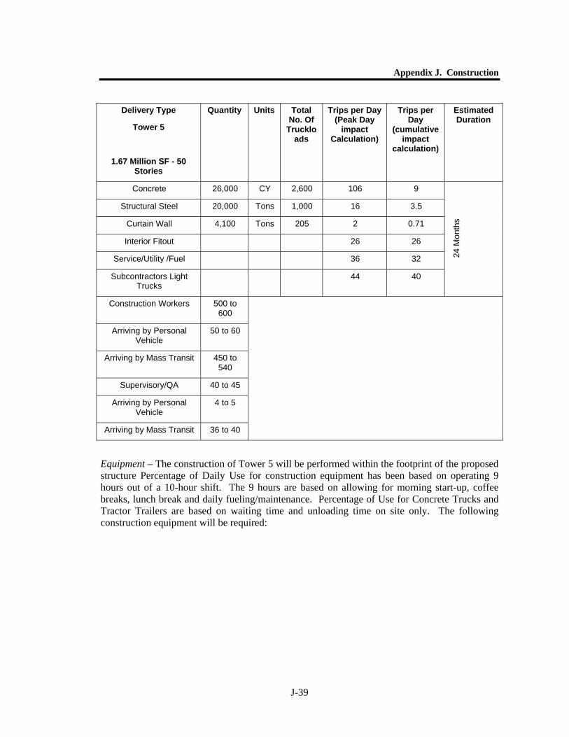
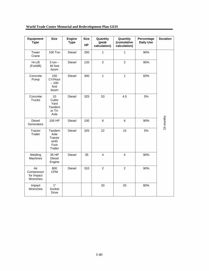
Equipment – The construction of Tower 5 will be performed within the footprint of the proposed structure Percentage of Daily Use for construction equipment has been based on operating 9 hours out of a 10-hour shift. The 9 hours are based on allowing for morning start-up, coffee breaks, lunch break and daily fueling/maintenance. Percentage of Use for Concrete Trucks and Tractor Trailers are based on waiting time and unloading time on site only. The following construction equipment will be required:
Delivery Type
Tower 5
1.67 Million SF - 50 Stories
Quantity Units Total No. Of
Truckloads
Trips per Day (Peak Day
impact Calculation)
Trips per Day
(cumulative impact
calculation)
Estimated Duration
Concrete 26,000 CY 2,600 106 9
Structural Steel 20,000 Tons 1,000 16 3.5
Curtain Wall 4,100 Tons 205 2 0.71
Interior Fitout 26 26
Service/Utility /Fuel 36 32
Subcontractors Light Trucks
44 40
24 M
onth
s
Construction Workers 500 to 600
Arriving by Personal Vehicle
50 to 60
Arriving by Mass Transit 450 to 540
Supervisory/QA 40 to 45
Arriving by Personal Vehicle
4 to 5
Arriving by Mass Transit 36 to 40
World Trade Center Memorial and Redevelopment Plan GEIS
J-40
Equipment Type
Size Engine Type
Size
HP
Quantity (peak
calculation)
Quantity (cumulative calculation)
Percentage Daily Use
Duration
Tower Crane
100 Ton Diesel 250 1 1 90%
Hi-Lift (Forklift)
5 ton – 40 foot boom
Diesel 120 2 2 90%
Concrete Pump
150 CY/Hour
– 100 foot
boom
Diesel 300 1 1 60%
Concrete Trucks
10 Cubic Yard
Tandem or Tri-Axle
Diesel 325 53 4.5 5%
Diesel Generators
100 HP Diesel 100 6 6 90%
Tractor Trailer
Tandem Axle
Tractor w/45 Foot
Trailer
Diesel 325 22 15 5%
Welding Machines
35 HP Diesel Engine
Diesel 35 4 4 90%
Air Compressor for Impact Wrenches
800 CFM
Diesel 310 2 2 90%
Impact Wrenches
1” Socket Drive
20 20 80%
24 m
onth
s
Appendix J. Construction
J-41
PERMANENT WTC PATH TERMINAL
(A) CONSTRUCTION METHODS AND IMPACTS
Permanent Tracks, Platform Conversion, Mezzanine and Concourse Construction (Zone 1) – Traffic and Construction Equipment
Construction period for this activity is estimated to consist of demolition and construction activities occurring simultaneously. Following the construction of a temporary sixth track adjacent to the westernmost existing fifth track, demolition and conversion activities would occur in 3 major sections, each further broken down into 2 components; a northern and a southern component (6 stages total). To maintain train service and passenger safety and access, only one half (either northern or southern half) would be demolished and converted then the second half would follow. This cycle, of stage, of activity would continue until all six tracks and platforms were converted.
Duration of completing all 6 stages is estimated to run for 21 months. All work estimated based on one 10-hour shift commencing at 0700 and running to 1800 Monday to Saturday. All work is within the west bathtub of the site with access from the existing ramp from Liberty Street. No street closings, lane closings or sidewalk closings are anticipated for this work to take place.
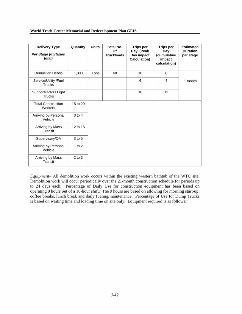
Demolition – Temporary sixth track to be built prior to any demolition and conversion activities. Demolition to occur in total of six stages. Demolition will occur on only the northern or southern half of platform and sets of tracks at one time to ensure continuous train service and passenger access. Estimated duration for demolition per stage is 24 days or 24 shifts. Demolition is included in the 3.5-month overall duration per stage.
World Trade Center Memorial and Redevelopment Plan GEIS
J-42
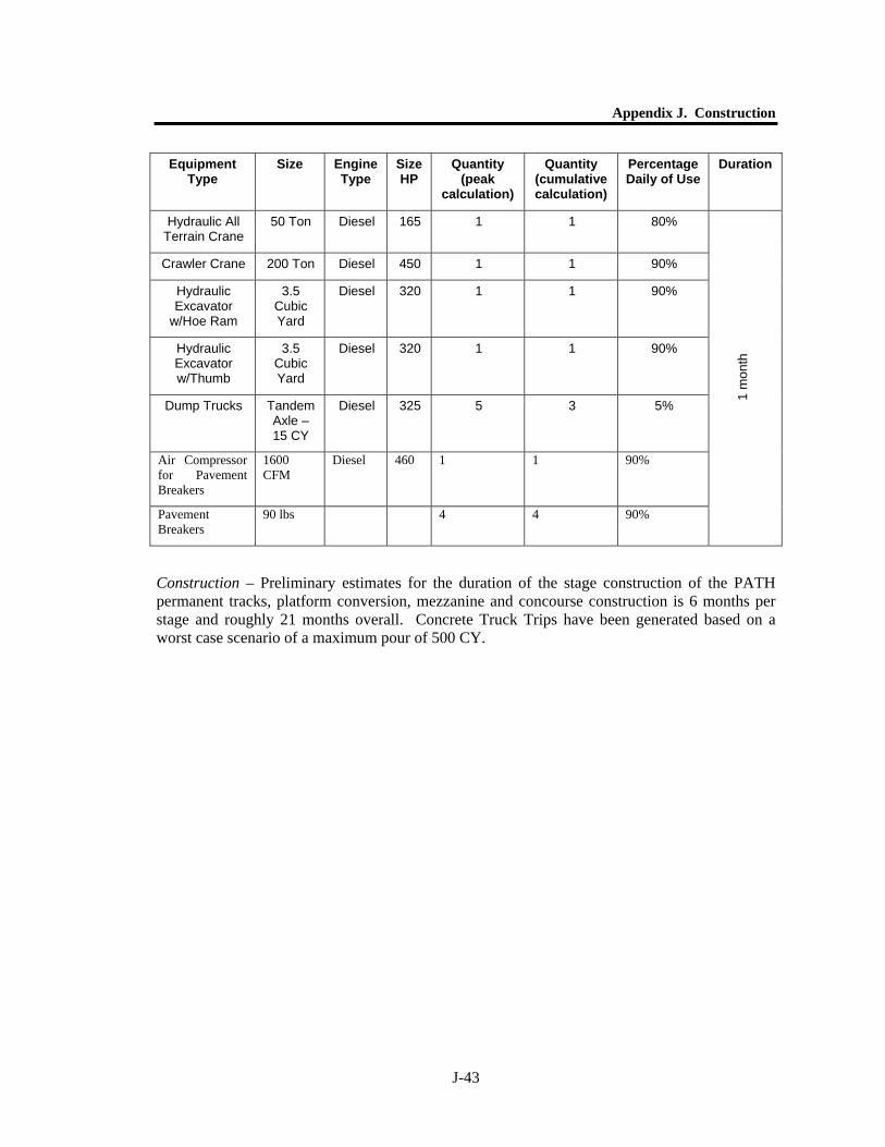
Equipment– All demolition work occurs within the existing western bathtub of the WTC site. Demolition work will occur periodically over the 21-month construction schedule for periods up to 24 days each. Percentage of Daily Use for construction equipment has been based on operating 9 hours out of a 10-hour shift. The 9 hours are based on allowing for morning start-up, coffee breaks, lunch break and daily fueling/maintenance. Percentage of Use for Dump Trucks is based on waiting time and loading time on site only. Equipment required is as follows:
Delivery Type
Per Stage (6 Stages total)
Quantity Units Total No. Of
Truckloads
Trips per Day (Peak Day impact Calculation)
Trips per Day
(cumulative impact
calculation)
Estimated Duration per stage
Demolition Debris 1,000 Tons 68 10 6
Service/Utility /Fuel Trucks
6 4
Subcontractors Light Trucks
16 12
1 month
Total Construction Workers
15 to 20
Arriving by Personal Vehicle
3 to 4
Arriving by Mass Transit
12 to 16
Supervisory/QA 3 to 5
Arriving by Personal Vehicle
1 to 2
Arriving by Mass Transit
2 to 3
Appendix J. Construction
J-43
Equipment Type
Size Engine Type
Size HP
Quantity (peak
calculation)
Quantity (cumulative calculation)
Percentage Daily of Use
Duration
Hydraulic All Terrain Crane
50 Ton Diesel 165 1 1 80%
Crawler Crane 200 Ton Diesel 450 1 1 90%
Hydraulic Excavator
w/Hoe Ram
3.5 Cubic Yard
Diesel 320 1 1 90%
Hydraulic Excavator w/Thumb
3.5 Cubic Yard
Diesel 320 1 1 90%
Dump Trucks Tandem Axle – 15 CY
Diesel 325 5 3 5%
Air Compressor for Pavement Breakers
1600 CFM
Diesel 460 1 1 90%
Pavement Breakers
90 lbs 4 4 90%
1 m
onth
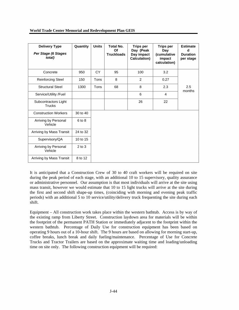
Construction – Preliminary estimates for the duration of the stage construction of the PATH permanent tracks, platform conversion, mezzanine and concourse construction is 6 months per stage and roughly 21 months overall. Concrete Truck Trips have been generated based on a worst case scenario of a maximum pour of 500 CY.
World Trade Center Memorial and Redevelopment Plan GEIS
J-44
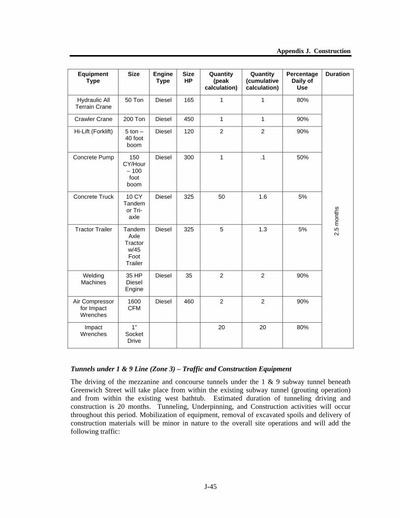
It is anticipated that a Construction Crew of 30 to 40 craft workers will be required on site during the peak period of each stage, with an additional 10 to 15 supervisory, quality assurance or administrative personnel. Our assumption is that most individuals will arrive at the site using mass transit, however we would estimate that 10 to 15 light trucks will arrive at the site during the first and second shift shape-up times, (coinciding with morning and evening peak traffic periods) with an additional 5 to 10 service/utility/delivery truck frequenting the site during each shift. Equipment – All construction work takes place within the western bathtub. Access is by way of the existing ramp from Liberty Street. Construction laydown area for materials will be within the footprint of the permanent PATH Station or immediately adjacent to the footprint within the western bathtub. Percentage of Daily Use for construction equipment has been based on operating 9 hours out of a 10-hour shift. The 9 hours are based on allowing for morning start-up, coffee breaks, lunch break and daily fueling/maintenance. Percentage of Use for Concrete Trucks and Tractor Trailers are based on the approximate waiting time and loading/unloading time on site only. The following construction equipment will be required:
Delivery Type
Per Stage (6 Stages total)
Quantity Units Total No. Of
Truckloads
Trips per Day (Peak Day impact Calculation)
Trips per Day
(cumulative impact
calculation)
Estimated
Duration per stage
Concrete 950 CY 95 100 3.2
Reinforcing Steel 150 Tons 8 2 0.27
Structural Steel 1300 Tons 68 8 2.3
Service/Utility /Fuel 6 4
Subcontractors Light Trucks
26 22
2.5 months
Construction Workers 30 to 40
Arriving by Personal Vehicle
6 to 8
Arriving by Mass Transit 24 to 32
Supervisory/QA 10 to 15
Arriving by Personal Vehicle
2 to 3
Arriving by Mass Transit 8 to 12
Appendix J. Construction
J-45
Equipment Type
Size Engine Type
Size HP
Quantity (peak
calculation)
Quantity (cumulative calculation)
Percentage Daily of
Use
Duration
Hydraulic All Terrain Crane
50 Ton Diesel 165 1 1 80%
Crawler Crane 200 Ton Diesel 450 1 1 90%
Hi-Lift (Forklift) 5 ton – 40 foot boom
Diesel 120 2 2 90%
Concrete Pump 150 CY/Hour
– 100 foot
boom
Diesel 300 1 .1 50%
Concrete Truck 10 CY Tandem or Tri-axle
Diesel 325 50 1.6 5%
Tractor Trailer Tandem Axle
Tractor w/45 Foot
Trailer
Diesel 325 5 1.3 5%
Welding Machines
35 HP Diesel Engine
Diesel 35 2 2 90%
Air Compressor for Impact Wrenches
1600 CFM
Diesel 460 2 2 90%
Impact Wrenches
1” Socket Drive
20 20 80% 2.
5 m
onth
s
Tunnels under 1 & 9 Line (Zone 3) – Traffic and Construction Equipment
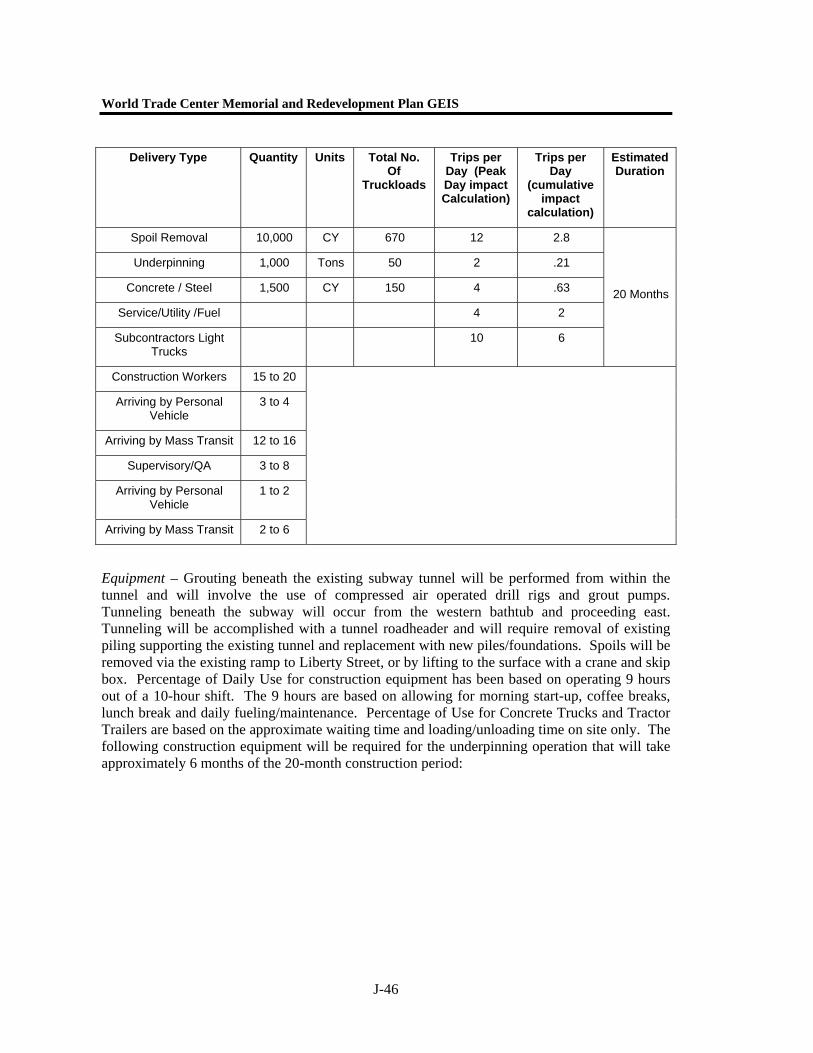
The driving of the mezzanine and concourse tunnels under the 1 & 9 subway tunnel beneath Greenwich Street will take place from within the existing subway tunnel (grouting operation) and from within the existing west bathtub. Estimated duration of tunneling driving and construction is 20 months. Tunneling, Underpinning, and Construction activities will occur throughout this period. Mobilization of equipment, removal of excavated spoils and delivery of construction materials will be minor in nature to the overall site operations and will add the following traffic:
World Trade Center Memorial and Redevelopment Plan GEIS
J-46
Equipment – Grouting beneath the existing subway tunnel will be performed from within the tunnel and will involve the use of compressed air operated drill rigs and grout pumps. Tunneling beneath the subway will occur from the western bathtub and proceeding east. Tunneling will be accomplished with a tunnel roadheader and will require removal of existing piling supporting the existing tunnel and replacement with new piles/foundations. Spoils will be removed via the existing ramp to Liberty Street, or by lifting to the surface with a crane and skip box. Percentage of Daily Use for construction equipment has been based on operating 9 hours out of a 10-hour shift. The 9 hours are based on allowing for morning start-up, coffee breaks, lunch break and daily fueling/maintenance. Percentage of Use for Concrete Trucks and Tractor Trailers are based on the approximate waiting time and loading/unloading time on site only. The following construction equipment will be required for the underpinning operation that will take approximately 6 months of the 20-month construction period:
Delivery Type Quantity Units Total No. Of
Truckloads
Trips per Day (Peak Day impact Calculation)
Trips per Day
(cumulative impact
calculation)
Estimated Duration
Spoil Removal 10,000 CY 670 12 2.8
Underpinning 1,000 Tons 50 2 .21
Concrete / Steel 1,500 CY 150 4 .63
Service/Utility /Fuel 4 2
Subcontractors Light Trucks
10 6
20 Months
Construction Workers 15 to 20
Arriving by Personal Vehicle
3 to 4
Arriving by Mass Transit 12 to 16
Supervisory/QA 3 to 8
Arriving by Personal Vehicle
1 to 2
Arriving by Mass Transit 2 to 6
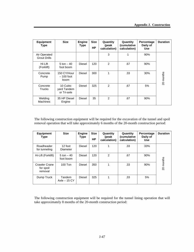
Appendix J. Construction
J-47
Equipment Type
Size Engine Type
Size
HP
Quantity (peak
calculation)
Quantity (cumulative calculation)
Percentage Daily of
Use
Duration
Air Operated Grout Drills
3 1 90%
Hi-Lift (Forklift)
5 ton – 40 foot boom
Diesel 120 2 .67 90%
Concrete Pump
150 CY/Hour – 100 foot
boom
Diesel 300 1 .33 30%
Concrete Trucks
10 Cubic yard Tandem
or Tri-axle
Diesel 325 2 .67 5%
Welding Machines
35 HP Diesel Engine
Diesel 35 2 .67 90%
20 m
onth
s
The following construction equipment will be required for the excavation of the tunnel and spoil removal operation that will take approximately 6 months of the 20-month construction period:
Equipment Type
Size Engine Type
Size
HP
Quantity (peak
calculation)
Quantity (cumulative calculation)
Percentage Daily of
Use
Duration
Roadheader for tunneling
12 foot Diameter
Diesel 120 1 .33 33%
Hi-Lift (Forklift) 5 ton – 40 foot boom
Diesel 120 2 .67 90%
Crawler Crane for spoil removal
100 Ton Diesel 350 1 .33 90%
Dump Truck Tandem Axle – 15 CY
Diesel 325 1 .33 5%
20 m
onth
s
The following construction equipment will be required for the tunnel lining operation that will take approximately 8 months of the 20-month construction period:

World Trade Center Memorial and Redevelopment Plan GEIS
J-48
Equipment Type
Size Engine Type
Size
HP
Quantity (peak
calculation)
Quantity (cumulative calculation)
Percentage Daily of
Use
Duration
Hi-Lift (Forklift)
5 ton – 40 foot boom
Diesel 120 2 .67 90%
Crawler Crane for
Material and Form support
100 Ton Diesel 350 1 .33 80%
Concrete Pump
150 CY/Hour – 100 foot
boom
Diesel 300 1 .33 30%
Concrete Trucks
10 Cubic yard Tandem
or Tri-axle
Diesel 325 1.4 .67 5%
Welding Machines
35 HP Diesel Engine
Diesel 35 2 .8 90%
20 m
onth
s
Tunnels and Concourses (Zones 2 & 4) – Traffic and Construction Equipment
The driving of the concourse tunnels under West and Church Streets will take place from within the existing west bathtub and the east bathtub in Zone 4 as described above. The West Street concourse will provide access to the World Financial Center under Route 9A and may be affected by the Route 9A project if the Short Bypass Alternative is selected. Estimated duration of underpinning, tunnel driving and construction is 15 months. Tunneling, Underpinning, and Construction activities will occur throughout this period. Mobilization of equipment, removal of excavated spoils and delivery of construction materials will be minor in nature to the overall site operations and will add the following traffic:

Appendix J. Construction
J-49
3a West Street Tunnel
Equipment – Tunneling beneath Liberty will occur from the western bathtub. Percentage of Daily Use for construction equipment has been based on operating 9 hours out of a 10-hour shift. The 9 hours are based on allowing for morning start-up, coffee breaks, lunch break and daily fueling/maintenance. Percentage of Use for Concrete Trucks and Dump Trucks are based on the approximate waiting time and loading/unloading time on site only. The following construction equipment will be required for the underpinning operation that will take approximately 5 months of the 15-month construction period (but may be assumed to be evenly distributed over the 15 month period:
Delivery Type Quantity Units Total No. Of
Truckloads
Trips per Day (Peak Day impact Calculation)
Trips per Day
(cumulative impact
calculation)
Estimated Duration
Spoil Removal 10,000 CY 670 10 3.7
Underpinning 1,000 Tons 50 2 .28
Concrete / Steel 1,500 CY 150 4 .83
Service/Utility /Fuel 4 2
Subcontractors Light Trucks
10 8
15 m
onth
s
Construction Workers 15 to 20
Arriving by Personal Vehicle
3 to 4
Arriving by Mass Transit 12 to 16
Supervisory/QA 3 to 8
Arriving by Personal Vehicle
1 to 2
Arriving by Mass Transit 2 to 6
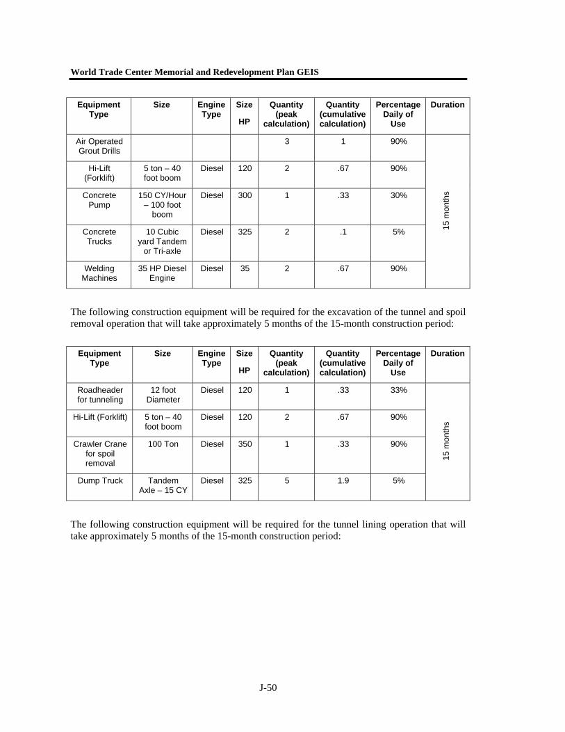
World Trade Center Memorial and Redevelopment Plan GEIS
J-50
Equipment Type
Size Engine Type
Size
HP
Quantity (peak
calculation)
Quantity (cumulative calculation)
Percentage Daily of
Use
Duration
Air Operated Grout Drills
3 1 90%
Hi-Lift (Forklift)
5 ton – 40 foot boom
Diesel 120 2 .67 90%
Concrete Pump
150 CY/Hour – 100 foot
boom
Diesel 300 1 .33 30%
Concrete Trucks
10 Cubic yard Tandem
or Tri-axle
Diesel 325 2 .1 5%
Welding Machines
35 HP Diesel Engine
Diesel 35 2 .67 90%
15 m
onth
s
The following construction equipment will be required for the excavation of the tunnel and spoil removal operation that will take approximately 5 months of the 15-month construction period:
Equipment Type
Size Engine Type
Size
HP
Quantity (peak
calculation)
Quantity (cumulative calculation)
Percentage Daily of
Use
Duration
Roadheader for tunneling
12 foot Diameter
Diesel 120 1 .33 33%
Hi-Lift (Forklift) 5 ton – 40 foot boom
Diesel 120 2 .67 90%
Crawler Crane for spoil removal
100 Ton Diesel 350 1 .33 90%
Dump Truck Tandem Axle – 15 CY
Diesel 325 5 1.9 5%
15 m
onth
s
The following construction equipment will be required for the tunnel lining operation that will take approximately 5 months of the 15-month construction period:
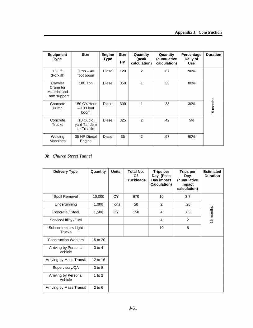
Appendix J. Construction
J-51
Equipment Type
Size Engine Type
Size
HP
Quantity (peak
calculation)
Quantity (cumulative calculation)
Percentage Daily of
Use
Duration
Hi-Lift (Forklift)
5 ton – 40 foot boom
Diesel 120 2 .67 90%
Crawler Crane for
Material and Form support
100 Ton Diesel 350 1 .33 80%
Concrete Pump
150 CY/Hour – 100 foot
boom
Diesel 300 1 .33 30%
Concrete Trucks
10 Cubic yard Tandem
or Tri-axle
Diesel 325 2 .42 5%
Welding Machines
35 HP Diesel Engine
Diesel 35 2 .67 90%
15 m
onth
s
3b Church Street Tunnel
Delivery Type Quantity Units Total No. Of
Truckloads
Trips per Day (Peak Day impact Calculation)
Trips per Day
(cumulative impact
calculation)
Estimated Duration
Spoil Removal 10,000 CY 670 10 3.7
Underpinning 1,000 Tons 50 2 .28
Concrete / Steel 1,500 CY 150 4 .83
Service/Utility /Fuel 4 2
Subcontractors Light Trucks
10 8
15 m
onth
s
Construction Workers 15 to 20
Arriving by Personal Vehicle
3 to 4
Arriving by Mass Transit 12 to 16
Supervisory/QA 3 to 8
Arriving by Personal Vehicle
1 to 2
Arriving by Mass Transit 2 to 6
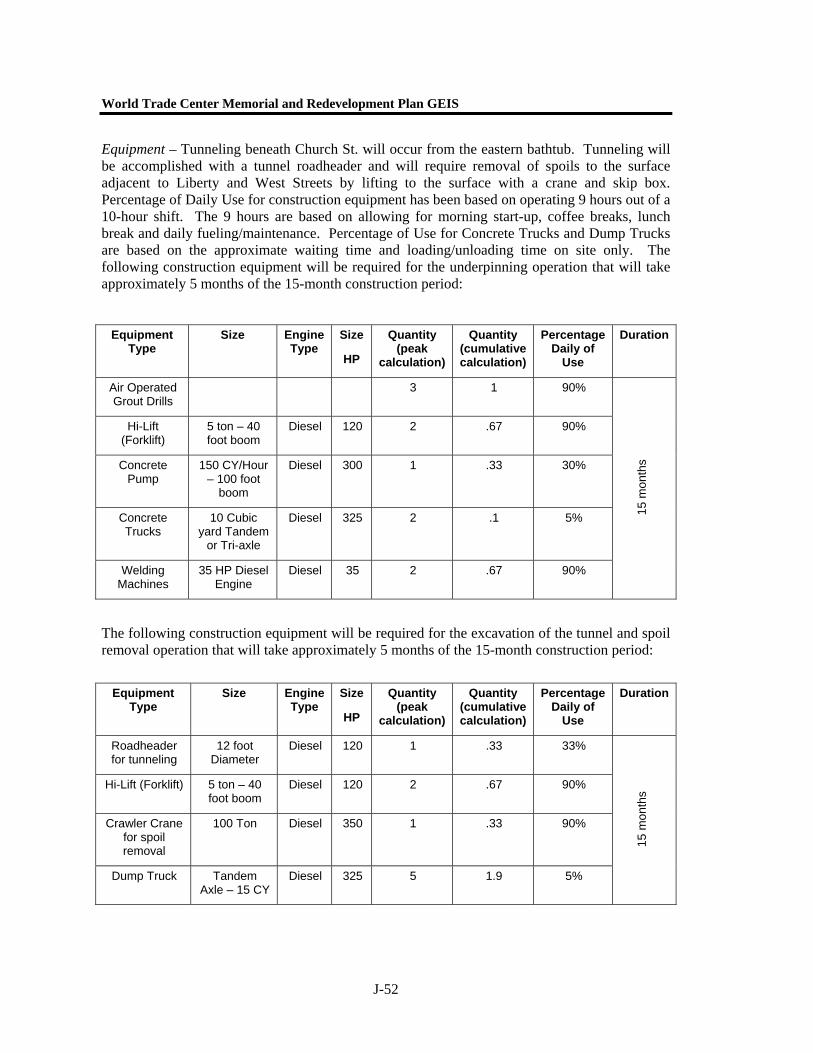
World Trade Center Memorial and Redevelopment Plan GEIS
J-52
Equipment – Tunneling beneath Church St. will occur from the eastern bathtub. Tunneling will be accomplished with a tunnel roadheader and will require removal of spoils to the surface adjacent to Liberty and West Streets by lifting to the surface with a crane and skip box. Percentage of Daily Use for construction equipment has been based on operating 9 hours out of a 10-hour shift. The 9 hours are based on allowing for morning start-up, coffee breaks, lunch break and daily fueling/maintenance. Percentage of Use for Concrete Trucks and Dump Trucks are based on the approximate waiting time and loading/unloading time on site only. The following construction equipment will be required for the underpinning operation that will take approximately 5 months of the 15-month construction period:
Equipment Type
Size Engine Type
Size
HP
Quantity (peak
calculation)
Quantity (cumulative calculation)
Percentage Daily of
Use
Duration
Air Operated Grout Drills
3 1 90%
Hi-Lift (Forklift)
5 ton – 40 foot boom
Diesel 120 2 .67 90%
Concrete Pump
150 CY/Hour – 100 foot
boom
Diesel 300 1 .33 30%
Concrete Trucks
10 Cubic yard Tandem
or Tri-axle
Diesel 325 2 .1 5%
Welding Machines
35 HP Diesel Engine
Diesel 35 2 .67 90%
15 m
onth
s
The following construction equipment will be required for the excavation of the tunnel and spoil removal operation that will take approximately 5 months of the 15-month construction period:
Equipment Type
Size Engine Type
Size
HP
Quantity (peak
calculation)
Quantity (cumulative calculation)
Percentage Daily of
Use
Duration
Roadheader for tunneling
12 foot Diameter
Diesel 120 1 .33 33%
Hi-Lift (Forklift) 5 ton – 40 foot boom
Diesel 120 2 .67 90%
Crawler Crane for spoil removal
100 Ton Diesel 350 1 .33 90%
Dump Truck Tandem Axle – 15 CY
Diesel 325 5 1.9 5%
15 m
onth
s
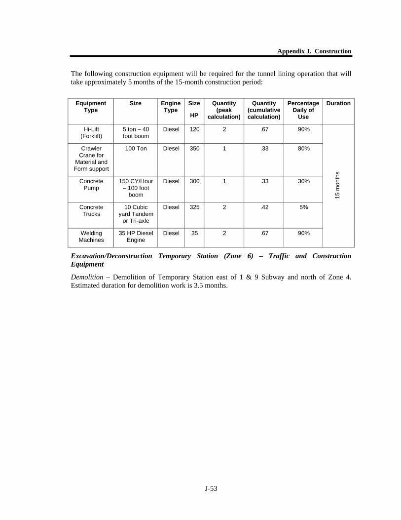
Appendix J. Construction
J-53
The following construction equipment will be required for the tunnel lining operation that will take approximately 5 months of the 15-month construction period:
Equipment Type
Size Engine Type
Size
HP
Quantity (peak
calculation)
Quantity (cumulative calculation)
Percentage Daily of
Use
Duration
Hi-Lift (Forklift)
5 ton – 40 foot boom
Diesel 120 2 .67 90%
Crawler Crane for
Material and Form support
100 Ton Diesel 350 1 .33 80%
Concrete Pump
150 CY/Hour – 100 foot
boom
Diesel 300 1 .33 30%
Concrete Trucks
10 Cubic yard Tandem
or Tri-axle
Diesel 325 2 .42 5%
Welding Machines
35 HP Diesel Engine
Diesel 35 2 .67 90%
15 m
onth
s
Excavation/Deconstruction Temporary Station (Zone 6) – Traffic and Construction Equipment
Demolition – Demolition of Temporary Station east of 1 & 9 Subway and north of Zone 4. Estimated duration for demolition work is 3.5 months.
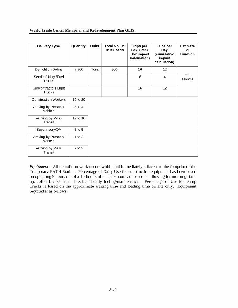
World Trade Center Memorial and Redevelopment Plan GEIS
J-54
Equipment – All demolition work occurs within and immediately adjacent to the footprint of the Temporary PATH Station. Percentage of Daily Use for construction equipment has been based on operating 9 hours out of a 10-hour shift. The 9 hours are based on allowing for morning start-up, coffee breaks, lunch break and daily fueling/maintenance. Percentage of Use for Dump Trucks is based on the approximate waiting time and loading time on site only. Equipment required is as follows:
Delivery Type Quantity Units Total No. Of Truckloads
Trips per Day (Peak Day impact Calculation)
Trips per Day
(cumulative impact
calculation)
Estimated
Duration
Demolition Debris 7,500 Tons 500 16 12
Service/Utility /Fuel Trucks
6 4
Subcontractors Light Trucks
16 12
3.5 Months
Construction Workers 15 to 20
Arriving by Personal Vehicle
3 to 4
Arriving by Mass Transit
12 to 16
Supervisory/QA 3 to 5
Arriving by Personal Vehicle
1 to 2
Arriving by Mass Transit
2 to 3

Appendix J. Construction
J-55
Equipment Type
Size Engine Type
Size HP
Quantity (peak
calculation)
Quantity (cumulative calculation)
Percentage Daily of
Use
Duration
Hydraulic All Terrain Crane
50 Ton Diesel 165 1 1 80%
Crawler Crane 200 Ton Diesel 450 1 1 90%
Hydraulic Excavator
w/Hoe Ram
3.5 Cubic Yard
Diesel 320 1 1 90%
Hydraulic Excavator w/Thumb
3.5 Cubic Yard
Diesel 320 1 1 90%
Hydraulic Excavator w/Grapple
3.5 Cubic Yard
Diesel 320 1 1 90%
Track Loader w/Waste Handling Bucket
5.5 Cubic Yard
Diesel 160 1 1 90%
Dump Trucks Tandem Axle – 15
CY
Diesel 325 8 6 5%
Air Compressor for Pavement
Breakers
1600 CFM Diesel 460 2 2 90%
Pavement Breakers
90 lbs. 12 12 80% 3.
5 m
onth
s
Excavation- It is assumed that sheet piling will be used at the northern and southern portions of Zone 6 to allow for removal following excavation and construction of pedestrian concourses.
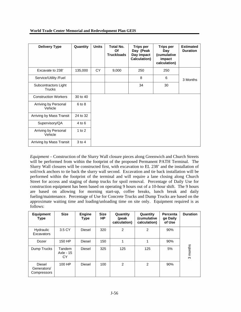
World Trade Center Memorial and Redevelopment Plan GEIS
J-56
Equipment – Construction of the Slurry Wall closure pieces along Greenwich and Church Streets will be performed from within the footprint of the proposed Permanent PATH Terminal. The Slurry Wall closures will be constructed first, with excavation to EL 238’ and the installation of soil/rock anchors to tie back the slurry wall second. Excavation and tie back installation will be performed within the footprint of the terminal and will require a lane closing along Church Street for access and staging of dump trucks for spoil removal. Percentage of Daily Use for construction equipment has been based on operating 9 hours out of a 10-hour shift. The 9 hours are based on allowing for morning start-up, coffee breaks, lunch break and daily fueling/maintenance. Percentage of Use for Concrete Trucks and Dump Trucks are based on the approximate waiting time and loading/unloading time on site only. Equipment required is as follows:
Equipment Type
Size Engine Type
Size HP
Quantity (peak
calculation)
Quantity (cumulative calculation)
Percentage Daily of Use
Duration
Hydraulic Excavators
3.5 CY Diesel 320 2 2 90%
Dozer 150 HP Diesel 150 1 1 90%
Dump Trucks Tandem Axle - 15
CY
Diesel 325 125 125 5%
Diesel Generators/
Compressors
100 HP Diesel 100 2 2 90%
3 m
onth
s
Delivery Type Quantity Units Total No. Of
Truckloads
Trips per Day (Peak Day impact Calculation)
Trips per Day
(cumulative impact
calculation)
Estimated Duration
Excavate to 238’ 135,000 CY 9,000 250 250
Service/Utility /Fuel 8 6
Subcontractors Light Trucks
34 30 3 Months
Construction Workers 30 to 40
Arriving by Personal Vehicle
6 to 8
Arriving by Mass Transit 24 to 32
Supervisory/QA 4 to 6
Arriving by Personal Vehicle
1 to 2
Arriving by Mass Transit 3 to 4

Appendix J. Construction
J-57
Construction of the PATH Terminal Building (Zone 6) – Traffic and Construction Equipment
Construction – Construction of the PATH Terminal Building includes construction of all sub-grade (El. 238’) and above grade levels. For the Grand Space it is anticipated that some of the structural steel framing will be pre-fabricated trusses to span the width of the Grand Space and may require lane closings on Church Street for erection. Assumes 500 CY concrete pours
Structural Framing
Delivery Type Quantity Units Total No. Of
Truckloads
Trips per Day (Peak Day impact Calculation)
Trips per Day (cumulative
impact calculation)
Estimated Duration
Concrete 12,000 CY 1,200 100 10
Reinforcing Steel 1,800 Tons 90 2 .75
Structural Steel to 306’
16,000 Tons 800 8 6.7
Structural Steel – Grand Space
3,000 Tons 150 4 1.25
Service/Utility /Fuel* 16 12
Subcontractors Light Trucks*
16 12
10 m
onth
s
Construction Workers
50 to 60
Arriving by Personal Vehicle
10 to 12
Arriving by Mass Transit
40 to 48
Supervisory/QA 10 to 15
Arriving by Personal Vehicle
2 to 3
Arriving by Mass Transit
8 to 12
* Service/Utility /Fuel/ Subcontractors Light Truck totals are constant throughout the construction of the Terminal. Where Structural Framing and “Glazing and Fitout” overlap, the Service/Utility /Fuel/
Subcontractors Light Truck totals are not additive (only count them once)
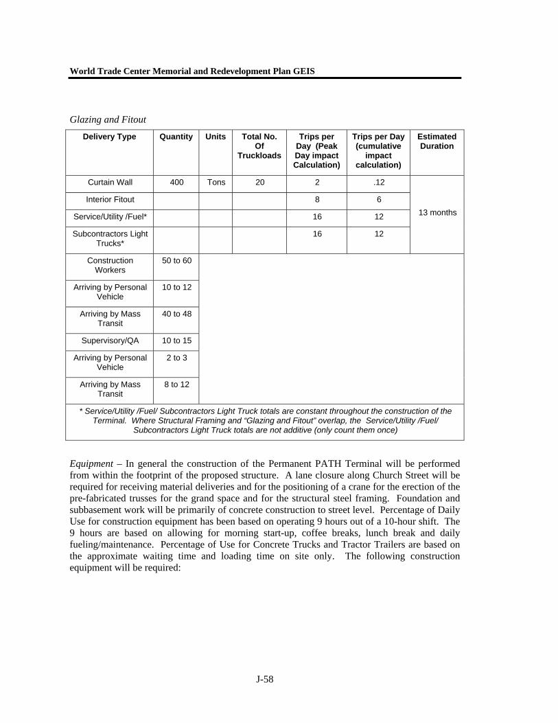
World Trade Center Memorial and Redevelopment Plan GEIS
J-58
Glazing and Fitout
Equipment – In general the construction of the Permanent PATH Terminal will be performed from within the footprint of the proposed structure. A lane closure along Church Street will be required for receiving material deliveries and for the positioning of a crane for the erection of the pre-fabricated trusses for the grand space and for the structural steel framing. Foundation and subbasement work will be primarily of concrete construction to street level. Percentage of Daily Use for construction equipment has been based on operating 9 hours out of a 10-hour shift. The 9 hours are based on allowing for morning start-up, coffee breaks, lunch break and daily fueling/maintenance. Percentage of Use for Concrete Trucks and Tractor Trailers are based on the approximate waiting time and loading time on site only. The following construction equipment will be required:
Delivery Type Quantity Units Total No. Of
Truckloads
Trips per Day (Peak Day impact Calculation)
Trips per Day (cumulative
impact calculation)
Estimated Duration
Curtain Wall 400 Tons 20 2 .12
Interior Fitout 8 6
Service/Utility /Fuel* 16 12
Subcontractors Light Trucks*
16 12
13 months
Construction Workers
50 to 60
Arriving by Personal Vehicle
10 to 12
Arriving by Mass Transit
40 to 48
Supervisory/QA 10 to 15
Arriving by Personal Vehicle
2 to 3
Arriving by Mass Transit
8 to 12
* Service/Utility /Fuel/ Subcontractors Light Truck totals are constant throughout the construction of the Terminal. Where Structural Framing and “Glazing and Fitout” overlap, the Service/Utility /Fuel/
Subcontractors Light Truck totals are not additive (only count them once)
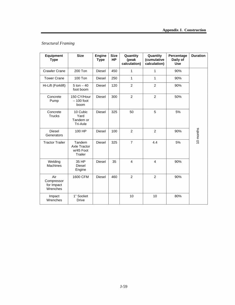
Appendix J. Construction
J-59
Structural Framing
Equipment Type
Size Engine Type
Size HP
Quantity (peak
calculation)
Quantity (cumulative calculation)
Percentage Daily of
Use
Duration
Crawler Crane 200 Ton Diesel 450 1 1 90%
Tower Crane 100 Ton Diesel 250 1 1 90%
Hi-Lift (Forklift) 5 ton – 40 foot boom
Diesel 120 2 2 90%
Concrete Pump
150 CY/Hour – 100 foot
boom
Diesel 300 2 2 50%
Concrete Trucks
10 Cubic Yard
Tandem or Tri-Axle
Diesel 325 50 5 5%
Diesel Generators
100 HP Diesel 100 2 2 90%
Tractor Trailer Tandem Axle Tractor w/45 Foot
Trailer
Diesel 325 7 4.4 5%
Welding Machines
35 HP Diesel Engine
Diesel 35 4 4 90%
Air Compressor for Impact Wrenches
1600 CFM Diesel 460 2 2 90%
Impact Wrenches
1” Socket Drive
10 10 80% 10
mon
ths
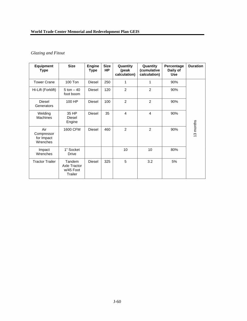
World Trade Center Memorial and Redevelopment Plan GEIS
J-60
Glazing and Fitout
Equipment Type
Size Engine Type
Size HP
Quantity (peak
calculation)
Quantity (cumulative calculation)
Percentage Daily of
Use
Duration
Tower Crane 100 Ton Diesel 250 1 1 90%
Hi-Lift (Forklift) 5 ton – 40 foot boom
Diesel 120 2 2 90%
Diesel Generators
100 HP Diesel 100 2 2 90%
Welding Machines
35 HP Diesel Engine
Diesel 35 4 4 90%
Air Compressor for Impact Wrenches
1600 CFM Diesel 460 2 2 90%
Impact Wrenches
1” Socket Drive
10 10 80%
Tractor Trailer Tandem Axle Tractor w/45 Foot
Trailer
Diesel 325 5 3.2 5%
13 m
onth
s
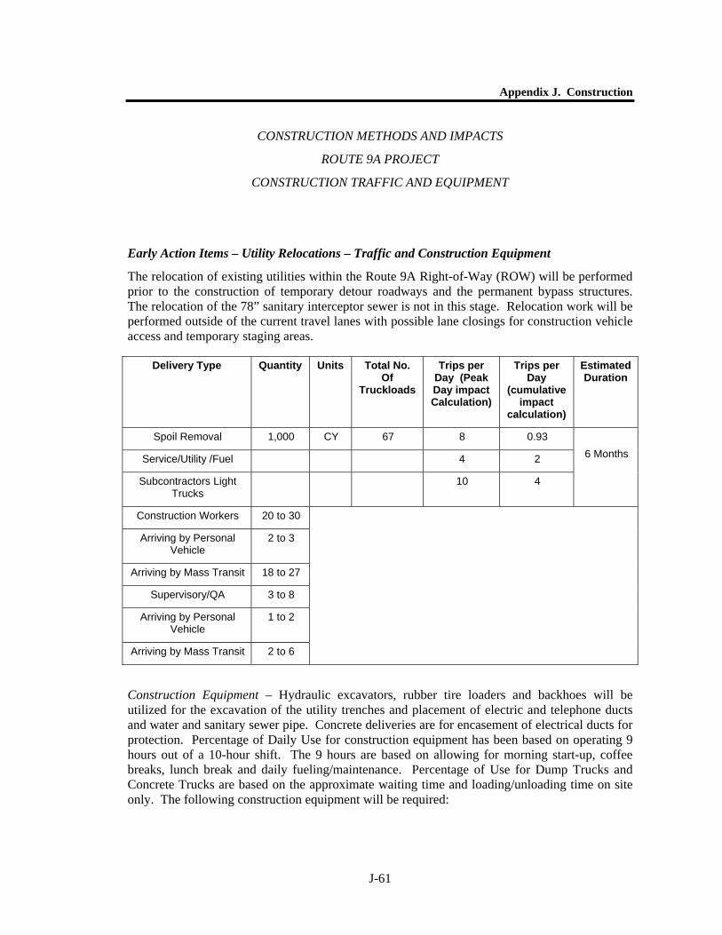
Appendix J. Construction
J-61
CONSTRUCTION METHODS AND IMPACTS
ROUTE 9A PROJECT
CONSTRUCTION TRAFFIC AND EQUIPMENT
Early Action Items – Utility Relocations – Traffic and Construction Equipment
The relocation of existing utilities within the Route 9A Right-of-Way (ROW) will be performed prior to the construction of temporary detour roadways and the permanent bypass structures. The relocation of the 78” sanitary interceptor sewer is not in this stage. Relocation work will be performed outside of the current travel lanes with possible lane closings for construction vehicle access and temporary staging areas.
Construction Equipment – Hydraulic excavators, rubber tire loaders and backhoes will be utilized for the excavation of the utility trenches and placement of electric and telephone ducts and water and sanitary sewer pipe. Concrete deliveries are for encasement of electrical ducts for protection. Percentage of Daily Use for construction equipment has been based on operating 9 hours out of a 10-hour shift. The 9 hours are based on allowing for morning start-up, coffee breaks, lunch break and daily fueling/maintenance. Percentage of Use for Dump Trucks and Concrete Trucks are based on the approximate waiting time and loading/unloading time on site only. The following construction equipment will be required:
Delivery Type Quantity Units Total No. Of
Truckloads
Trips per Day (Peak Day impact Calculation)
Trips per Day
(cumulative impact
calculation)
Estimated Duration
Spoil Removal 1,000 CY 67 8 0.93
Service/Utility /Fuel 4 2
Subcontractors Light Trucks
10 4
6 Months
Construction Workers 20 to 30
Arriving by Personal Vehicle
2 to 3
Arriving by Mass Transit 18 to 27
Supervisory/QA 3 to 8
Arriving by Personal Vehicle
1 to 2
Arriving by Mass Transit 2 to 6
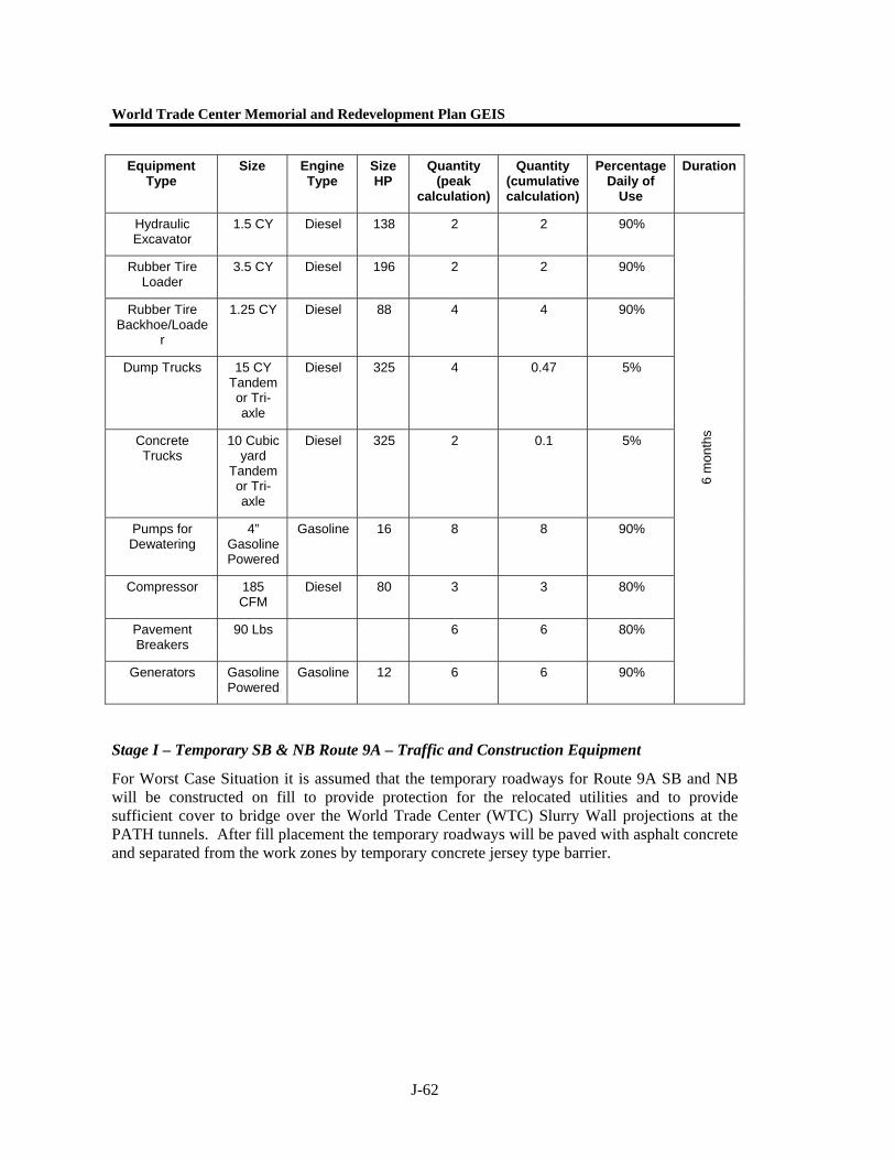
World Trade Center Memorial and Redevelopment Plan GEIS
J-62
Equipment Type
Size Engine Type
Size HP
Quantity (peak
calculation)
Quantity (cumulative calculation)
Percentage Daily of
Use
Duration
Hydraulic Excavator
1.5 CY Diesel 138 2 2 90%
Rubber Tire Loader
3.5 CY Diesel 196 2 2 90%
Rubber Tire Backhoe/Loade
r
1.25 CY Diesel 88 4 4 90%
Dump Trucks 15 CY Tandem or Tri-axle
Diesel 325 4 0.47 5%
Concrete Trucks
10 Cubic yard
Tandem or Tri-axle
Diesel 325 2 0.1 5%
Pumps for Dewatering
4” Gasoline Powered
Gasoline 16 8 8 90%
Compressor 185 CFM
Diesel 80 3 3 80%
Pavement Breakers
90 Lbs 6 6 80%
Generators Gasoline Powered
Gasoline 12 6 6 90%
6 m
onth
s
Stage I – Temporary SB & NB Route 9A – Traffic and Construction Equipment
For Worst Case Situation it is assumed that the temporary roadways for Route 9A SB and NB will be constructed on fill to provide protection for the relocated utilities and to provide sufficient cover to bridge over the World Trade Center (WTC) Slurry Wall projections at the PATH tunnels. After fill placement the temporary roadways will be paved with asphalt concrete and separated from the work zones by temporary concrete jersey type barrier.
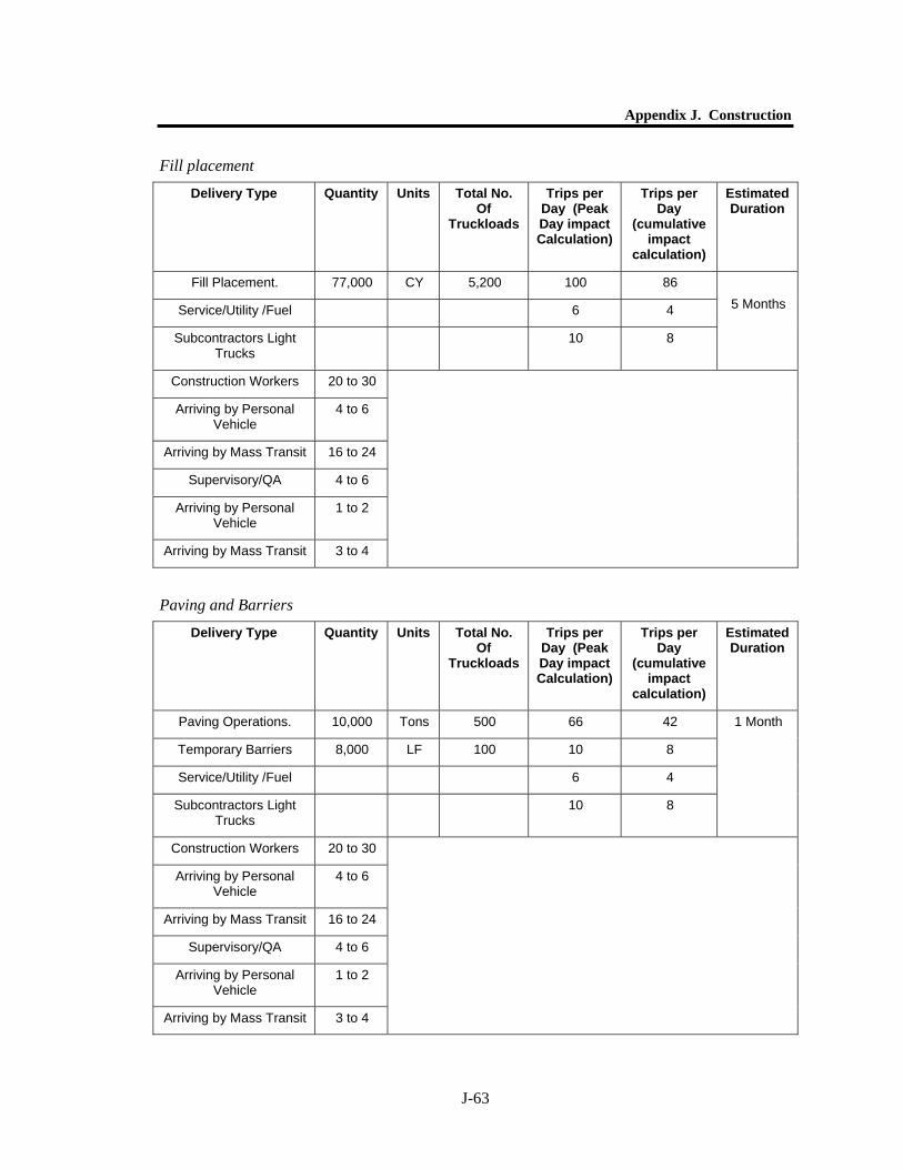
Appendix J. Construction
J-63
Fill placement
Paving and Barriers
Delivery Type Quantity Units Total No. Of
Truckloads
Trips per Day (Peak Day impact Calculation)
Trips per Day
(cumulative impact
calculation)
Estimated Duration
Fill Placement. 77,000 CY 5,200 100 86
Service/Utility /Fuel 6 4
Subcontractors Light Trucks
10 8
5 Months
Construction Workers 20 to 30
Arriving by Personal Vehicle
4 to 6
Arriving by Mass Transit 16 to 24
Supervisory/QA 4 to 6
Arriving by Personal Vehicle
1 to 2
Arriving by Mass Transit 3 to 4
Delivery Type Quantity Units Total No. Of
Truckloads
Trips per Day (Peak Day impact Calculation)
Trips per Day
(cumulative impact
calculation)
Estimated Duration
Paving Operations. 10,000 Tons 500 66 42
Temporary Barriers 8,000 LF 100 10 8
Service/Utility /Fuel 6 4
Subcontractors Light Trucks
10 8
1 Month
Construction Workers 20 to 30
Arriving by Personal Vehicle
4 to 6
Arriving by Mass Transit 16 to 24
Supervisory/QA 4 to 6
Arriving by Personal Vehicle
1 to 2
Arriving by Mass Transit 3 to 4
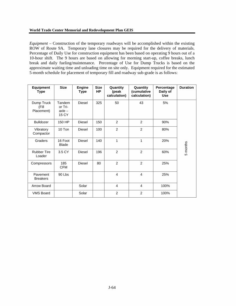
World Trade Center Memorial and Redevelopment Plan GEIS
J-64
Equipment – Construction of the temporary roadways will be accomplished within the existing ROW of Route 9A. Temporary lane closures may be required for the delivery of materials. Percentage of Daily Use for construction equipment has been based on operating 9 hours out of a 10-hour shift. The 9 hours are based on allowing for morning start-up, coffee breaks, lunch break and daily fueling/maintenance. Percentage of Use for Dump Trucks is based on the approximate waiting time and unloading time on site only. Equipment required for the estimated 5-month schedule for placement of temporary fill and roadway sub-grade is as follows:
Equipment Type
Size Engine Type
Size HP
Quantity (peak
calculation)
Quantity (cumulative calculation)
Percentage Daily of
Use
Duration
Dump Truck (Fill
Placement)
Tandem or Tri-axle – 15 CY
Diesel 325 50 43 5%
Bulldozer 150 HP Diesel 150 2 2 90%
Vibratory Compactor
10 Ton Diesel 100 2 2 80%
Graders 16 Foot Blade
Diesel 140 1 1 20%
Rubber Tire Loader
3.5 CY Diesel 196 2 2 60%
Compressors 185 CFM
Diesel 80 2 2 25%
Pavement Breakers
90 Lbs 4 4 25%
Arrow Board Solar 4 4 100%
VMS Board Solar 2 2 100%
5 m
onth
s
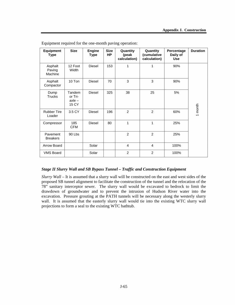
Appendix J. Construction
J-65
Equipment required for the one-month paving operation:
Equipment Type
Size Engine Type
Size HP
Quantity (peak
calculation)
Quantity (cumulative calculation)
Percentage Daily of
Use
Duration
Asphalt Paving
Machine
12 Foot Width
Diesel 153 1 1 90%
Asphalt Compactor
10 Ton Diesel 70 3 3 90%
Dump Trucks
Tandem or Tri-axle – 15 CY
Diesel 325 38 25 5%
Rubber Tire Loader
3.5 CY Diesel 196 2 2 60%
Compressor 185 CFM
Diesel 80 1 1 25%
Pavement Breakers
90 Lbs 2 2 25%
Arrow Board Solar 4 4 100%
VMS Board Solar 2 2 100%
1 m
onth
Stage II Slurry Wall and SB Bypass Tunnel – Traffic and Construction Equipment
Slurry Wall – It is assumed that a slurry wall will be constructed on the east and west sides of the proposed SB tunnel alignment to facilitate the construction of the tunnel and the relocation of the 78” sanitary interceptor sewer. The slurry wall would be excavated to bedrock to limit the drawdown of groundwater and to prevent the intrusion of Hudson River water into the excavation. Pressure grouting at the PATH tunnels will be necessary along the westerly slurry wall. It is assumed that the easterly slurry wall would tie into the existing WTC slurry wall projections to form a seal to the existing WTC bathtub.
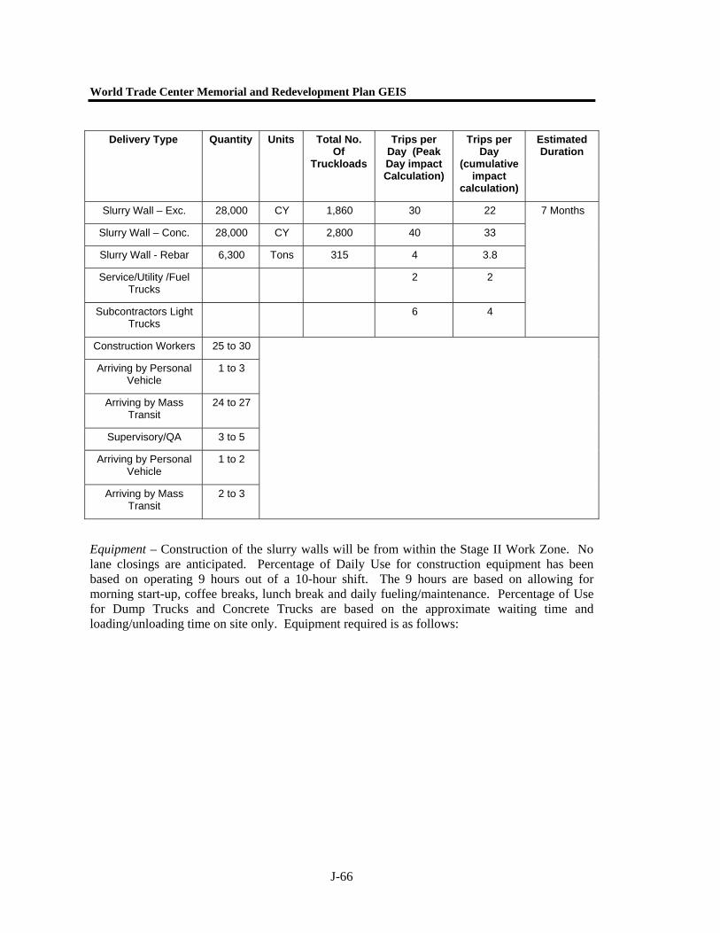
World Trade Center Memorial and Redevelopment Plan GEIS
J-66
Equipment – Construction of the slurry walls will be from within the Stage II Work Zone. No lane closings are anticipated. Percentage of Daily Use for construction equipment has been based on operating 9 hours out of a 10-hour shift. The 9 hours are based on allowing for morning start-up, coffee breaks, lunch break and daily fueling/maintenance. Percentage of Use for Dump Trucks and Concrete Trucks are based on the approximate waiting time and loading/unloading time on site only. Equipment required is as follows:
Delivery Type Quantity Units Total No. Of
Truckloads
Trips per Day (Peak Day impact Calculation)
Trips per Day
(cumulative impact
calculation)
Estimated Duration
Slurry Wall – Exc. 28,000 CY 1,860 30 22
Slurry Wall – Conc. 28,000 CY 2,800 40 33
Slurry Wall - Rebar 6,300 Tons 315 4 3.8
Service/Utility /Fuel Trucks
2 2
Subcontractors Light Trucks
6 4
7 Months
Construction Workers 25 to 30
Arriving by Personal Vehicle
1 to 3
Arriving by Mass Transit
24 to 27
Supervisory/QA 3 to 5
Arriving by Personal Vehicle
1 to 2
Arriving by Mass Transit
2 to 3
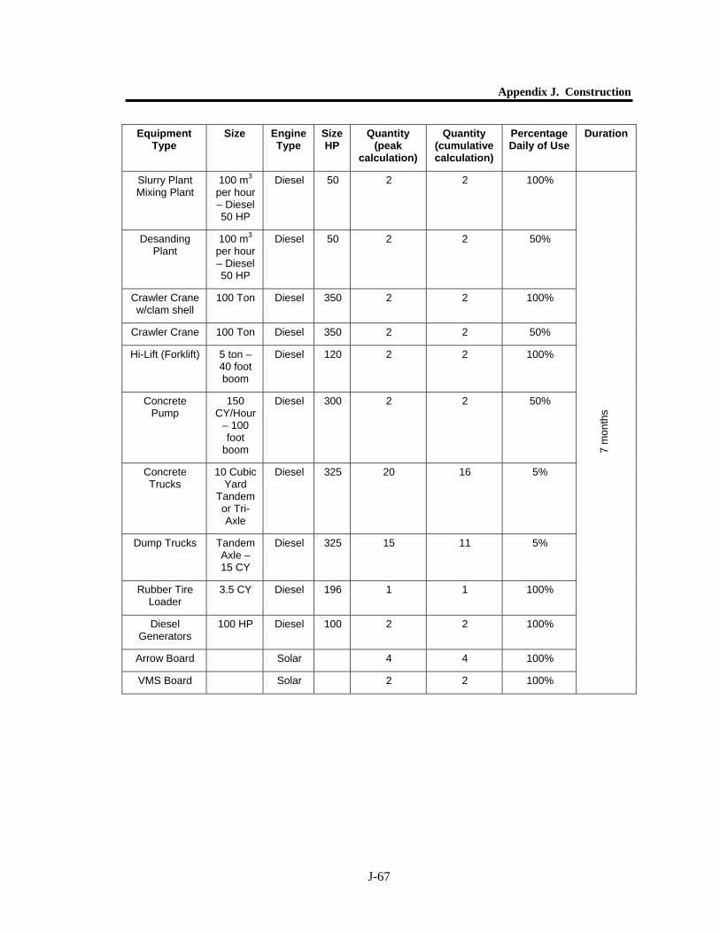
Appendix J. Construction
J-67
Equipment Type
Size Engine Type
Size HP
Quantity (peak
calculation)
Quantity (cumulative calculation)
Percentage Daily of Use
Duration
Slurry Plant Mixing Plant
100 m3 per hour – Diesel 50 HP
Diesel 50 2 2 100%
Desanding Plant
100 m3 per hour – Diesel 50 HP
Diesel 50 2 2 50%
Crawler Crane w/clam shell
100 Ton Diesel 350 2 2 100%
Crawler Crane 100 Ton Diesel 350 2 2 50%
Hi-Lift (Forklift) 5 ton – 40 foot boom
Diesel 120 2 2 100%
Concrete Pump
150 CY/Hour
– 100 foot
boom
Diesel 300 2 2 50%
Concrete Trucks
10 Cubic Yard
Tandem or Tri-Axle
Diesel 325 20 16 5%
Dump Trucks Tandem Axle – 15 CY
Diesel 325 15 11 5%
Rubber Tire Loader
3.5 CY Diesel 196 1 1 100%
Diesel Generators
100 HP Diesel 100 2 2 100%
Arrow Board Solar 4 4 100%
VMS Board Solar 2 2 100%
7 m
onth
s

World Trade Center Memorial and Redevelopment Plan GEIS
J-68
Excavation – After the slurry wall is complete, the excavation for the SB Bypass Tunnel will be performed. The entire width between slurry walls will be excavated to the proposed invert of the sub-grade for the tunnel. It is assumed that temporary struts bridging the excavation will be utilized to support the slurry wall.
Equipment – Excavation work will be performed within the Stage II Work Zone and should not require any additional lane closings. Excavated spoils will be removed from the site by dump truck following the proposed truck routes. Percentage of Daily Use for construction equipment has been based on operating 9 hours out of a 10-hour shift. The 9 hours are based on allowing for morning start-up, coffee breaks, lunch break and daily fueling/maintenance. Percentage of Use for Dump Trucks is based on the approximate waiting time and loading time on site only. Equipment required is as follows:
Delivery Type Quantity Units Total No. Of Loads
Trips per Day (Peak Day impact Calculation)
Trips per Day (cumulative
impact calculation)
Estimated Duration per stage
Excavate to Invert 125,000 CY 8,300 230 230
Service/Utility /Fuel Trucks
8 6
Subcontractors Light Trucks
6 4
3 Months
Total Construction Workers
20 to 25
Arriving by Personal Vehicle
4 to 5
Arriving by Mass Transit
16 to 20
Supervisory/QA 3 to 5
Arriving by Personal Vehicle
1 to 2
Arriving by Mass Transit
2 to 3
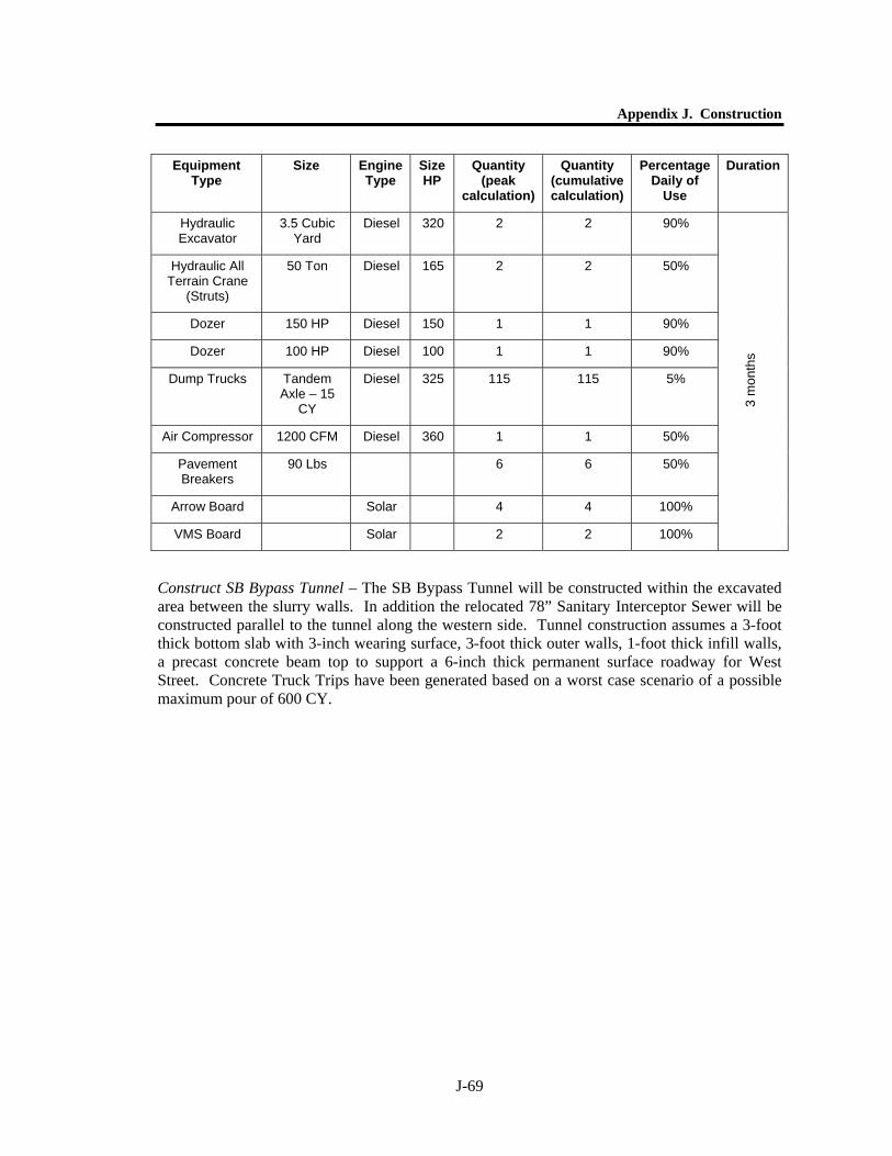
Appendix J. Construction
J-69
Construct SB Bypass Tunnel – The SB Bypass Tunnel will be constructed within the excavated area between the slurry walls. In addition the relocated 78” Sanitary Interceptor Sewer will be constructed parallel to the tunnel along the western side. Tunnel construction assumes a 3-foot thick bottom slab with 3-inch wearing surface, 3-foot thick outer walls, 1-foot thick infill walls, a precast concrete beam top to support a 6-inch thick permanent surface roadway for West Street. Concrete Truck Trips have been generated based on a worst case scenario of a possible maximum pour of 600 CY.
Equipment Type
Size Engine Type
Size HP
Quantity (peak
calculation)
Quantity (cumulative calculation)
Percentage Daily of
Use
Duration
Hydraulic Excavator
3.5 Cubic Yard
Diesel 320 2 2 90%
Hydraulic All Terrain Crane
(Struts)
50 Ton Diesel 165 2 2 50%
Dozer 150 HP Diesel 150 1 1 90%
Dozer 100 HP Diesel 100 1 1 90%
Dump Trucks Tandem Axle – 15
CY
Diesel 325 115 115 5%
Air Compressor 1200 CFM Diesel 360 1 1 50%
Pavement Breakers
90 Lbs 6 6 50%
Arrow Board Solar 4 4 100%
VMS Board Solar 2 2 100%
3 m
onth
s
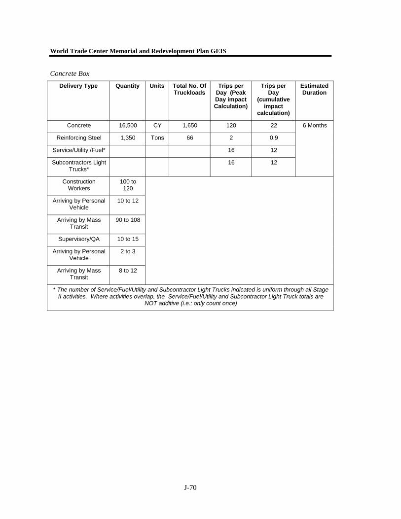
World Trade Center Memorial and Redevelopment Plan GEIS
J-70
Concrete Box
Delivery Type Quantity Units Total No. Of Truckloads
Trips per Day (Peak Day impact Calculation)
Trips per Day
(cumulative impact
calculation)
Estimated Duration
Concrete 16,500 CY 1,650 120 22
Reinforcing Steel 1,350 Tons 66 2 0.9
Service/Utility /Fuel* 16 12
Subcontractors Light Trucks*
16 12
6 Months
Construction Workers
100 to 120
Arriving by Personal Vehicle
10 to 12
Arriving by Mass Transit
90 to 108
Supervisory/QA 10 to 15
Arriving by Personal Vehicle
2 to 3
Arriving by Mass Transit
8 to 12
* The number of Service/Fuel/Utility and Subcontractor Light Trucks indicated is uniform through all Stage II activities. Where activities overlap, the Service/Fuel/Utility and Subcontractor Light Truck totals are
NOT additive (i.e.: only count once)
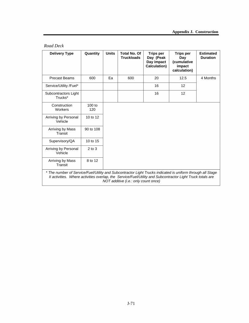
Appendix J. Construction
J-71
Road Deck
Delivery Type Quantity Units Total No. Of Truckloads
Trips per Day (Peak Day impact Calculation)
Trips per Day
(cumulative impact
calculation)
Estimated Duration
Precast Beams 600 Ea 600 20 12.5
Service/Utility /Fuel* 16 12
Subcontractors Light Trucks*
16 12
4 Months
Construction Workers
100 to 120
Arriving by Personal Vehicle
10 to 12
Arriving by Mass Transit
90 to 108
Supervisory/QA 10 to 15
Arriving by Personal Vehicle
2 to 3
Arriving by Mass Transit
8 to 12
* The number of Service/Fuel/Utility and Subcontractor Light Trucks indicated is uniform through all Stage II activities. Where activities overlap, the Service/Fuel/Utility and Subcontractor Light Truck totals are
NOT additive (i.e.: only count once)

World Trade Center Memorial and Redevelopment Plan GEIS
J-72
Backfill
Delivery Type Quantity Units Total No. Of Truckloads
Trips per Day (Peak Day
impact Calculation)
Trips per Day (cumulative
impact calculation)
Estimated Duration
Backfill Tunnel & 78” Int.
13,000 CY 890 76 76
Service/Utility /Fuel* 16 12
Subcontractors Light Trucks*
16 12
1 Month
Construction Workers
100 to 120
Arriving by Personal Vehicle
10 to 12
Arriving by Mass Transit
90 to 108
Supervisory/QA 10 to 15
Arriving by Personal Vehicle
2 to 3
Arriving by Mass Transit
8 to 12
* The number of Service/Fuel/Utility and Subcontractor Light Trucks indicated is uniform through all Stage II activities. Where activities overlap, the Service/Fuel/Utility and Subcontractor Light Truck totals are NOT
additive (i.e.: only count once)
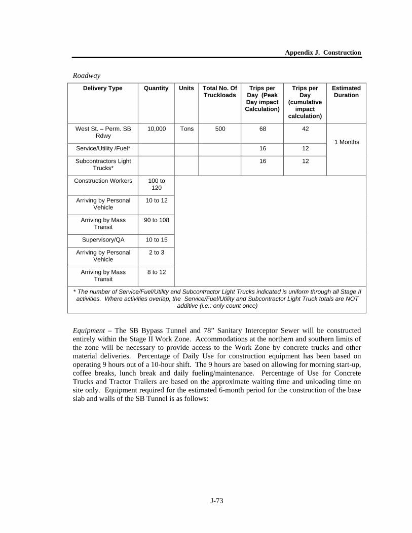
Appendix J. Construction
J-73
Roadway
Equipment – The SB Bypass Tunnel and 78” Sanitary Interceptor Sewer will be constructed entirely within the Stage II Work Zone. Accommodations at the northern and southern limits of the zone will be necessary to provide access to the Work Zone by concrete trucks and other material deliveries. Percentage of Daily Use for construction equipment has been based on operating 9 hours out of a 10-hour shift. The 9 hours are based on allowing for morning start-up, coffee breaks, lunch break and daily fueling/maintenance. Percentage of Use for Concrete Trucks and Tractor Trailers are based on the approximate waiting time and unloading time on site only. Equipment required for the estimated 6-month period for the construction of the base slab and walls of the SB Tunnel is as follows:
Delivery Type Quantity Units Total No. Of Truckloads
Trips per Day (Peak Day impact Calculation)
Trips per Day
(cumulative impact
calculation)
Estimated Duration
West St. – Perm. SB Rdwy
10,000 Tons 500 68 42
Service/Utility /Fuel* 16 12
Subcontractors Light Trucks*
16 12
1 Months
Construction Workers 100 to 120
Arriving by Personal Vehicle
10 to 12
Arriving by Mass Transit
90 to 108
Supervisory/QA 10 to 15
Arriving by Personal Vehicle
2 to 3
Arriving by Mass Transit
8 to 12
* The number of Service/Fuel/Utility and Subcontractor Light Trucks indicated is uniform through all Stage II activities. Where activities overlap, the Service/Fuel/Utility and Subcontractor Light Truck totals are NOT
additive (i.e.: only count once)
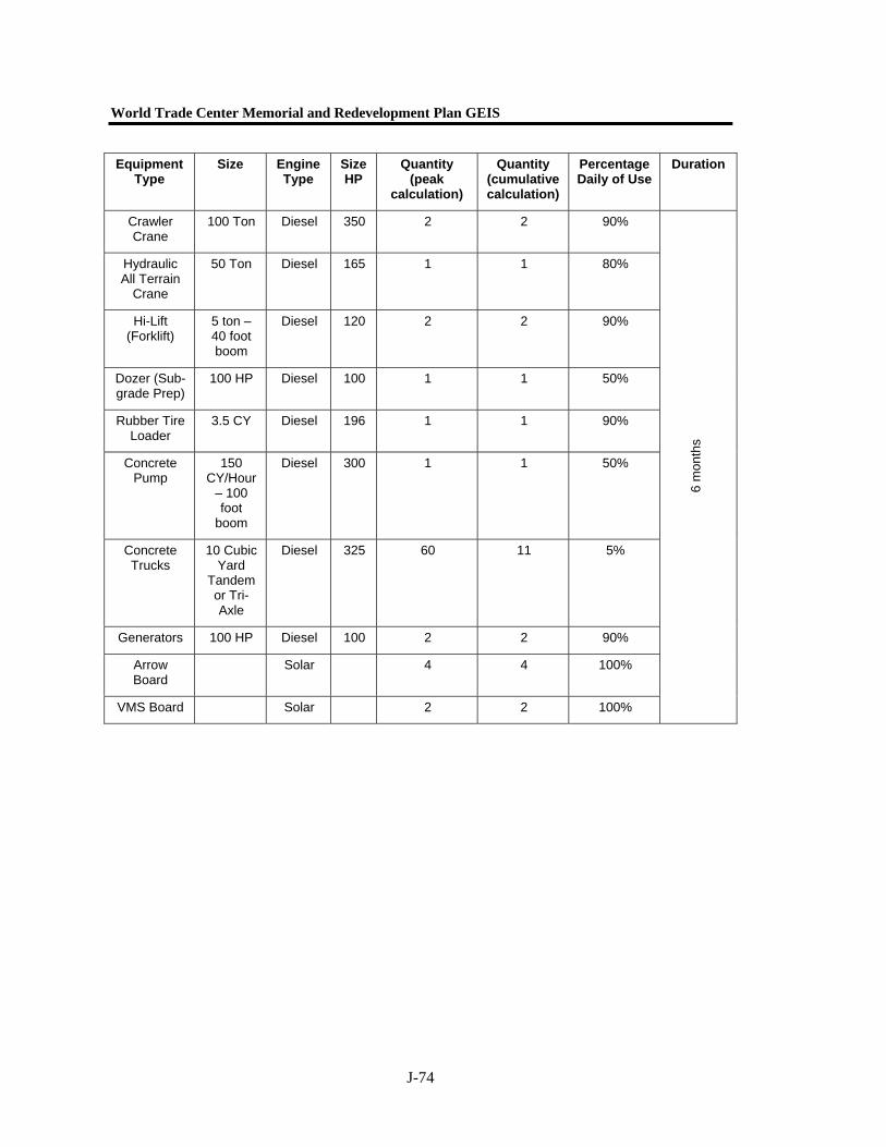
World Trade Center Memorial and Redevelopment Plan GEIS
J-74
Equipment Type
Size Engine Type
Size HP
Quantity (peak
calculation)
Quantity (cumulative calculation)
Percentage Daily of Use
Duration
Crawler Crane
100 Ton Diesel 350 2 2 90%
Hydraulic All Terrain
Crane
50 Ton Diesel 165 1 1 80%
Hi-Lift (Forklift)
5 ton – 40 foot boom
Diesel 120 2 2 90%
Dozer (Sub-grade Prep)
100 HP Diesel 100 1 1 50%
Rubber Tire Loader
3.5 CY Diesel 196 1 1 90%
Concrete Pump
150 CY/Hour
– 100 foot
boom
Diesel 300 1 1 50%
Concrete Trucks
10 Cubic Yard
Tandem or Tri-Axle
Diesel 325 60 11 5%
Generators 100 HP Diesel 100 2 2 90%
Arrow Board
Solar 4 4 100%
VMS Board Solar 2 2 100% 6
mon
ths
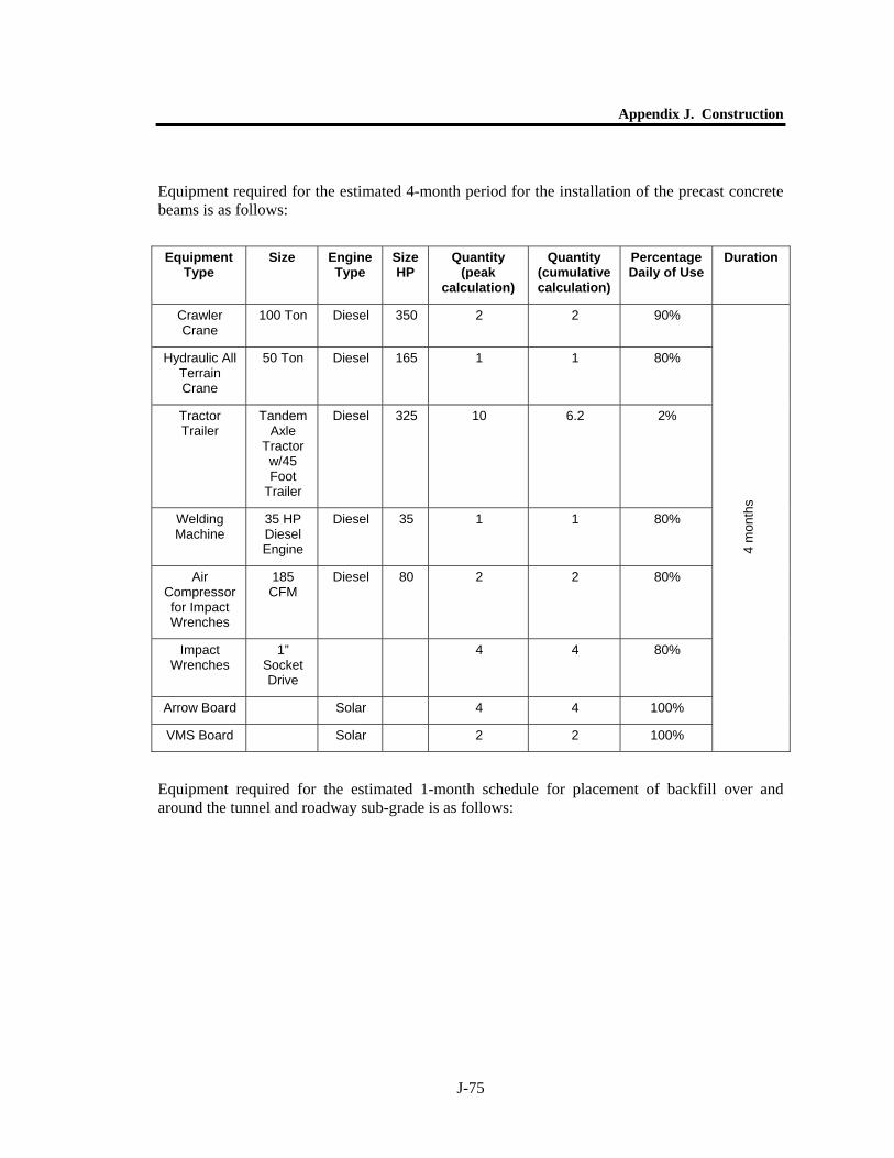
Appendix J. Construction
J-75
Equipment required for the estimated 4-month period for the installation of the precast concrete beams is as follows:
Equipment required for the estimated 1-month schedule for placement of backfill over and around the tunnel and roadway sub-grade is as follows:
Equipment Type
Size Engine Type
Size HP
Quantity (peak
calculation)
Quantity (cumulative calculation)
Percentage Daily of Use
Duration
Crawler Crane
100 Ton Diesel 350 2 2 90%
Hydraulic All Terrain Crane
50 Ton Diesel 165 1 1 80%
Tractor Trailer
Tandem Axle
Tractor w/45 Foot
Trailer
Diesel 325 10 6.2 2%
Welding Machine
35 HP Diesel Engine
Diesel 35 1 1 80%
Air Compressor for Impact Wrenches
185 CFM
Diesel 80 2 2 80%
Impact Wrenches
1” Socket Drive
4 4 80%
Arrow Board Solar 4 4 100%
VMS Board Solar 2 2 100% 4
mon
ths
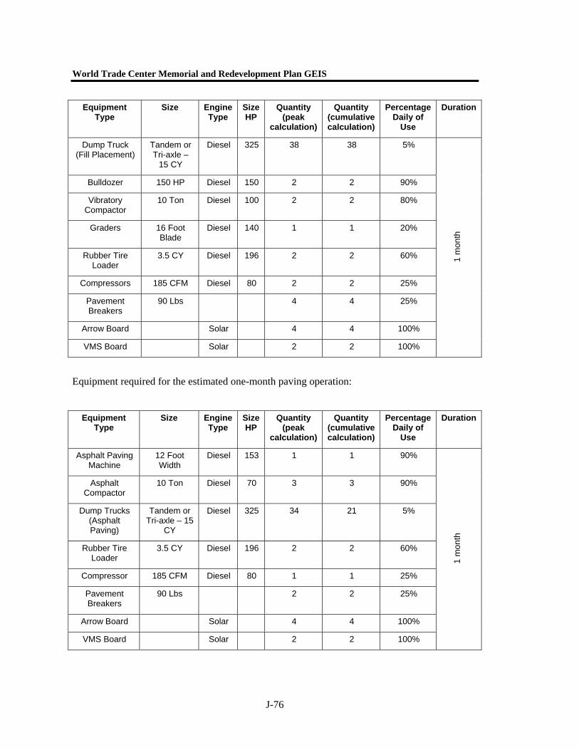
World Trade Center Memorial and Redevelopment Plan GEIS
J-76
Equipment required for the estimated one-month paving operation:
Equipment Type
Size Engine Type
Size HP
Quantity (peak
calculation)
Quantity (cumulative calculation)
Percentage Daily of
Use
Duration
Dump Truck (Fill Placement)
Tandem or Tri-axle –
15 CY
Diesel 325 38 38 5%
Bulldozer 150 HP Diesel 150 2 2 90%
Vibratory Compactor
10 Ton Diesel 100 2 2 80%
Graders 16 Foot Blade
Diesel 140 1 1 20%
Rubber Tire Loader
3.5 CY Diesel 196 2 2 60%
Compressors 185 CFM Diesel 80 2 2 25%
Pavement Breakers
90 Lbs 4 4 25%
Arrow Board Solar 4 4 100%
VMS Board Solar 2 2 100%
1 m
onth
Equipment Type
Size Engine Type
Size HP
Quantity (peak
calculation)
Quantity (cumulative calculation)
Percentage Daily of
Use
Duration
Asphalt Paving Machine
12 Foot Width
Diesel 153 1 1 90%
Asphalt Compactor
10 Ton Diesel 70 3 3 90%
Dump Trucks (Asphalt Paving)
Tandem or Tri-axle – 15
CY
Diesel 325 34 21 5%
Rubber Tire Loader
3.5 CY Diesel 196 2 2 60%
Compressor 185 CFM Diesel 80 1 1 25%
Pavement Breakers
90 Lbs 2 2 25%
Arrow Board Solar 4 4 100%
VMS Board Solar 2 2 100%
1 m
onth
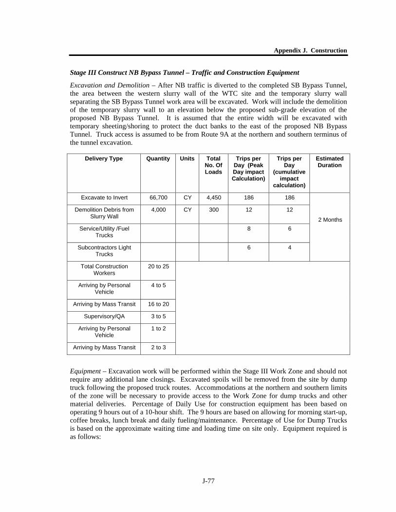
Appendix J. Construction
J-77
Stage III Construct NB Bypass Tunnel – Traffic and Construction Equipment
Excavation and Demolition – After NB traffic is diverted to the completed SB Bypass Tunnel, the area between the western slurry wall of the WTC site and the temporary slurry wall separating the SB Bypass Tunnel work area will be excavated. Work will include the demolition of the temporary slurry wall to an elevation below the proposed sub-grade elevation of the proposed NB Bypass Tunnel. It is assumed that the entire width will be excavated with temporary sheeting/shoring to protect the duct banks to the east of the proposed NB Bypass Tunnel. Truck access is assumed to be from Route 9A at the northern and southern terminus of the tunnel excavation.
Equipment – Excavation work will be performed within the Stage III Work Zone and should not require any additional lane closings. Excavated spoils will be removed from the site by dump truck following the proposed truck routes. Accommodations at the northern and southern limits of the zone will be necessary to provide access to the Work Zone for dump trucks and other material deliveries. Percentage of Daily Use for construction equipment has been based on operating 9 hours out of a 10-hour shift. The 9 hours are based on allowing for morning start-up, coffee breaks, lunch break and daily fueling/maintenance. Percentage of Use for Dump Trucks is based on the approximate waiting time and loading time on site only. Equipment required is as follows:
Delivery Type Quantity Units Total No. Of Loads
Trips per Day (Peak Day impact Calculation)
Trips per Day
(cumulative impact
calculation)
Estimated Duration
Excavate to Invert 66,700 CY 4,450 186 186
Demolition Debris from Slurry Wall
4,000 CY 300 12 12
Service/Utility /Fuel Trucks
8 6
Subcontractors Light Trucks
6 4
2 Months
Total Construction Workers
20 to 25
Arriving by Personal Vehicle
4 to 5
Arriving by Mass Transit 16 to 20
Supervisory/QA 3 to 5
Arriving by Personal Vehicle
1 to 2
Arriving by Mass Transit 2 to 3
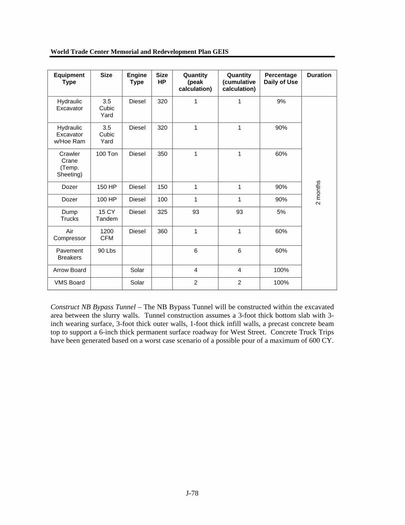
World Trade Center Memorial and Redevelopment Plan GEIS
J-78
Construct NB Bypass Tunnel – The NB Bypass Tunnel will be constructed within the excavated area between the slurry walls. Tunnel construction assumes a 3-foot thick bottom slab with 3-inch wearing surface, 3-foot thick outer walls, 1-foot thick infill walls, a precast concrete beam top to support a 6-inch thick permanent surface roadway for West Street. Concrete Truck Trips have been generated based on a worst case scenario of a possible pour of a maximum of 600 CY.
Equipment Type
Size Engine Type
Size HP
Quantity (peak
calculation)
Quantity (cumulative calculation)
Percentage Daily of Use
Duration
Hydraulic Excavator
3.5 Cubic Yard
Diesel 320 1 1 9%
Hydraulic Excavator
w/Hoe Ram
3.5 Cubic Yard
Diesel 320 1 1 90%
Crawler Crane (Temp.
Sheeting)
100 Ton Diesel 350 1 1 60%
Dozer 150 HP Diesel 150 1 1 90%
Dozer 100 HP Diesel 100 1 1 90%
Dump Trucks
15 CY Tandem
Diesel 325 93 93 5%
Air Compressor
1200 CFM
Diesel 360 1 1 60%
Pavement Breakers
90 Lbs 6 6 60%
Arrow Board Solar 4 4 100%
VMS Board Solar 2 2 100%
2 m
onth
s
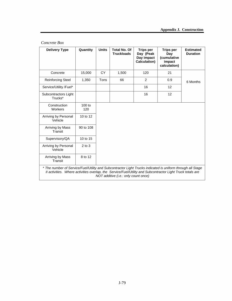
Appendix J. Construction
J-79
Concrete Box
Delivery Type Quantity Units Total No. Of Truckloads
Trips per Day (Peak Day impact Calculation)
Trips per Day
(cumulative impact
calculation)
Estimated Duration
Concrete 15,000 CY 1,500 120 21
Reinforcing Steel 1,350 Tons 66 2 0.9
Service/Utility /Fuel* 16 12
Subcontractors Light Trucks*
16 12
6 Months
Construction Workers
100 to 120
Arriving by Personal Vehicle
10 to 12
Arriving by Mass Transit
90 to 108
Supervisory/QA 10 to 15
Arriving by Personal Vehicle
2 to 3
Arriving by Mass Transit
8 to 12
* The number of Service/Fuel/Utility and Subcontractor Light Trucks indicated is uniform through all Stage II activities. Where activities overlap, the Service/Fuel/Utility and Subcontractor Light Truck totals are
NOT additive (i.e.: only count once)
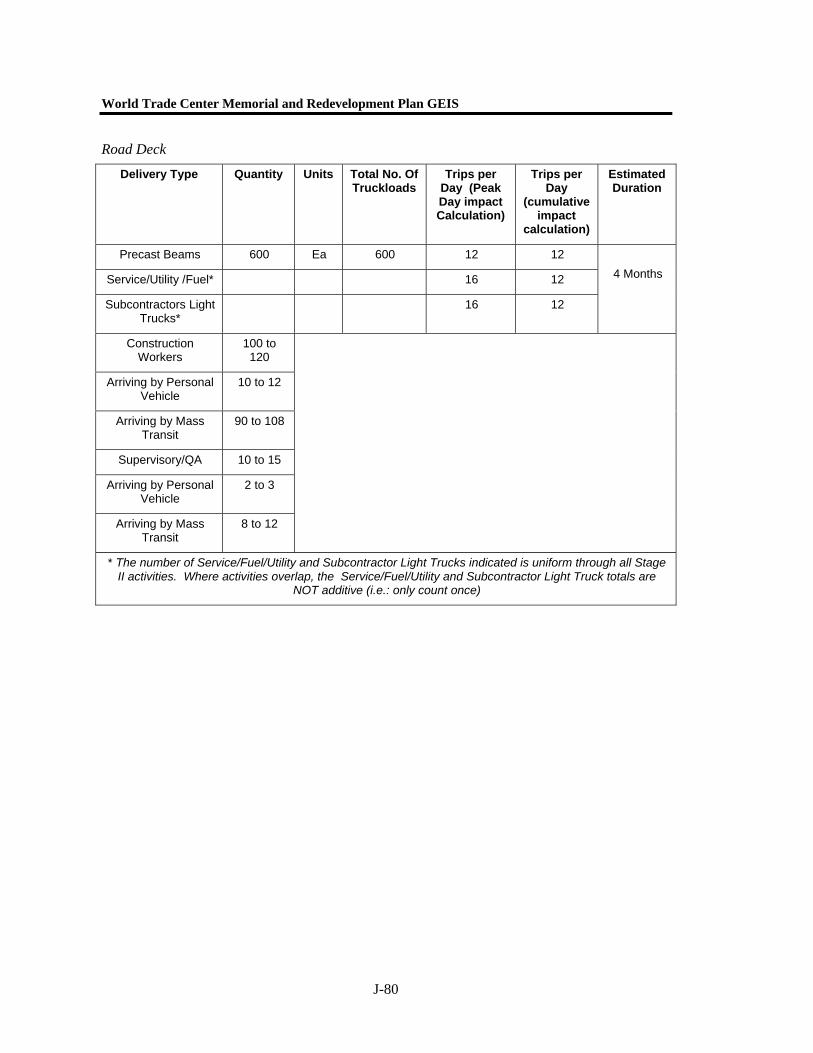
World Trade Center Memorial and Redevelopment Plan GEIS
J-80
Road Deck
Delivery Type Quantity Units Total No. Of Truckloads
Trips per Day (Peak Day impact Calculation)
Trips per Day
(cumulative impact
calculation)
Estimated Duration
Precast Beams 600 Ea 600 12 12
Service/Utility /Fuel* 16 12
Subcontractors Light Trucks*
16 12
4 Months
Construction Workers
100 to 120
Arriving by Personal Vehicle
10 to 12
Arriving by Mass Transit
90 to 108
Supervisory/QA 10 to 15
Arriving by Personal Vehicle
2 to 3
Arriving by Mass Transit
8 to 12
* The number of Service/Fuel/Utility and Subcontractor Light Trucks indicated is uniform through all Stage II activities. Where activities overlap, the Service/Fuel/Utility and Subcontractor Light Truck totals are
NOT additive (i.e.: only count once)
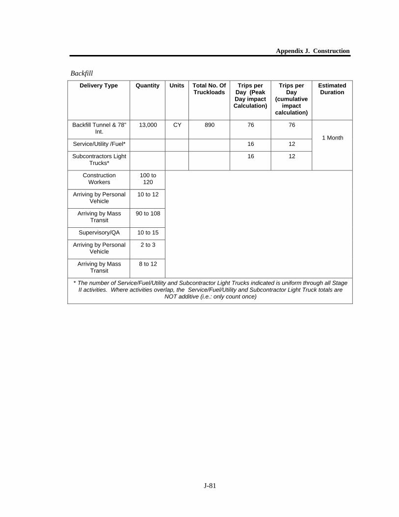
Appendix J. Construction
J-81
Backfill
Delivery Type Quantity Units Total No. Of Truckloads
Trips per Day (Peak Day impact Calculation)
Trips per Day
(cumulative impact
calculation)
Estimated Duration
Backfill Tunnel & 78” Int.
13,000 CY 890 76 76
Service/Utility /Fuel* 16 12
Subcontractors Light Trucks*
16 12
1 Month
Construction Workers
100 to 120
Arriving by Personal Vehicle
10 to 12
Arriving by Mass Transit
90 to 108
Supervisory/QA 10 to 15
Arriving by Personal Vehicle
2 to 3
Arriving by Mass Transit
8 to 12
* The number of Service/Fuel/Utility and Subcontractor Light Trucks indicated is uniform through all Stage II activities. Where activities overlap, the Service/Fuel/Utility and Subcontractor Light Truck totals are
NOT additive (i.e.: only count once)

World Trade Center Memorial and Redevelopment Plan GEIS
J-82
Roadway
Equipment – The NB Bypass Tunnel will be constructed entirely within the Stage III Work Zone. Accommodations at the northern and southern limits of the Work Zone will be necessary to provide access to the Work Zone by concrete trucks and other material deliveries. Percentage of Daily Use for construction equipment has been based on operating 9 hours out of a 10-hour shift. The 9 hours are based on allowing for morning start-up, coffee breaks, lunch break and daily fueling/maintenance. Percentage of Use for Concrete Trucks and Tractor Trailers are based on the approximate waiting time and unloading time on site only. Equipment required for the estimated 6-month period for the construction of the base slab and walls of the NB Tunnel is as follows:
Delivery Type Quantity Units Total No. Of Truckloads
Trips per Day (Peak Day impact Calculation)
Trips per Day
(cumulative impact
calculation)
Estimated Duration
West St. – Perm. SB Rdwy
10,000 Tons 500 68 42
Service/Utility /Fuel* 16 12
Subcontractors Light Trucks*
16 12
1 Months
Construction Workers
100 to 120
Arriving by Personal Vehicle
10 to 12
Arriving by Mass Transit
90 to 108
Supervisory/QA 10 to 15
Arriving by Personal Vehicle
2 to 3
Arriving by Mass Transit
8 to 12
* The number of Service/Fuel/Utility and Subcontractor Light Trucks indicated is uniform through all Stage II activities. Where activities overlap, the Service/Fuel/Utility and Subcontractor Light Truck totals are
NOT additive (i.e.: only count once)

Appendix J. Construction
J-83
Equipment Type
Size Engine Type
Size HP
Quantity (peak
calculation)
Quantity (cumulative calculation)
Percentage Daily of
Use
Duration
Crawler Crane 100 Ton Diesel 350 2 2 90%
Hydraulic All Terrain Crane
50 Ton Diesel 165 1 1 80%
Hi-Lift (Forklift) 5 ton – 40 foot boom
Diesel 120 2 2 90%
Dozer (Sub-grade Prep)
100 HP Diesel 100 1 1 50%
Rubber Tire Loader
3.5 CY Diesel 196 1 1 90%
Concrete Pump
150 CY/Hour – 100 foot boom
Diesel 300 1 1 50%
Concrete Trucks
10 Cubic Yard
Tandem or Tri-Axle
Diesel 325 60 10.5 5%
Generators 100 HP Diesel 100 2 2 90%
Arrow Board Solar 4 4 100%
VMS Board Solar 2 2 100%
6 m
onth
s
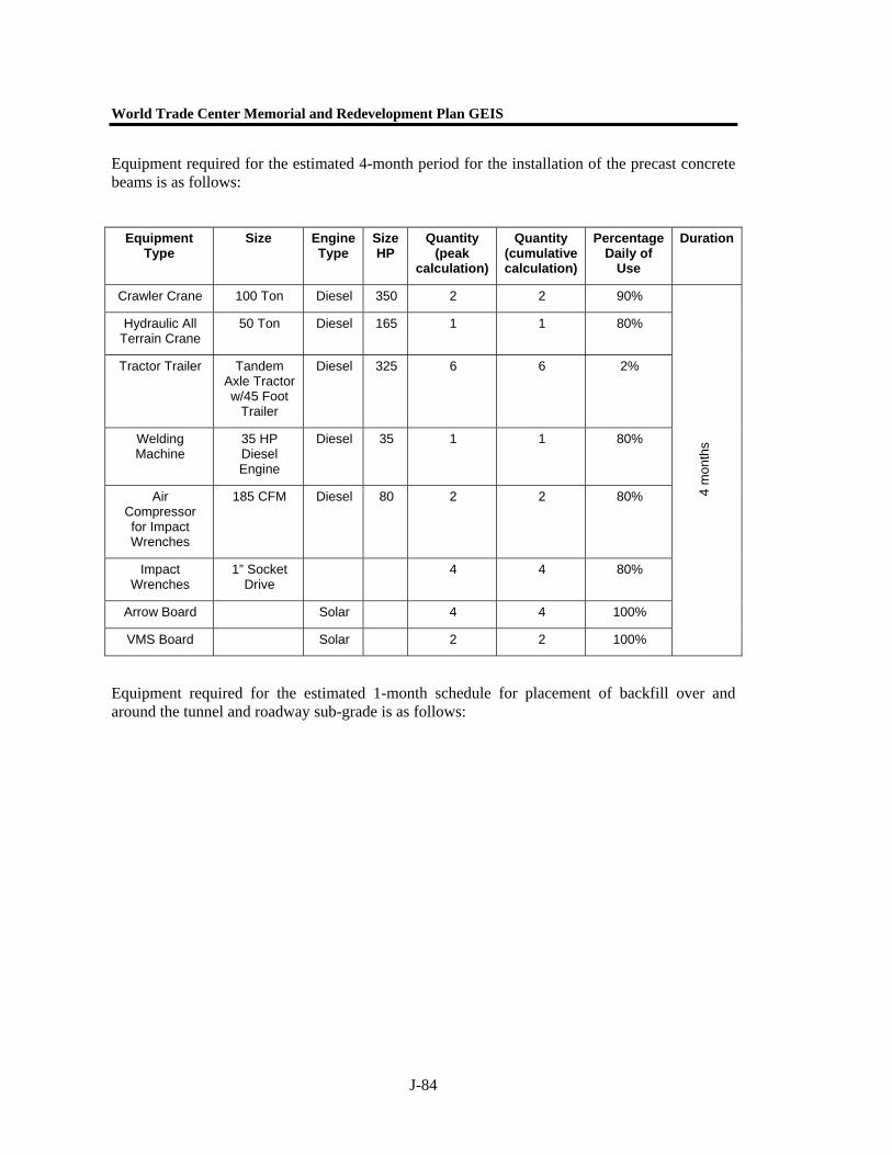
World Trade Center Memorial and Redevelopment Plan GEIS
J-84
Equipment required for the estimated 4-month period for the installation of the precast concrete beams is as follows:
Equipment required for the estimated 1-month schedule for placement of backfill over and around the tunnel and roadway sub-grade is as follows:
Equipment Type
Size Engine Type
Size HP
Quantity (peak
calculation)
Quantity (cumulative calculation)
Percentage Daily of
Use
Duration
Crawler Crane 100 Ton Diesel 350 2 2 90%
Hydraulic All Terrain Crane
50 Ton Diesel 165 1 1 80%
Tractor Trailer Tandem Axle Tractor w/45 Foot
Trailer
Diesel 325 6 6 2%
Welding Machine
35 HP Diesel Engine
Diesel 35 1 1 80%
Air Compressor for Impact Wrenches
185 CFM Diesel 80 2 2 80%
Impact Wrenches
1” Socket Drive
4 4 80%
Arrow Board Solar 4 4 100%
VMS Board Solar 2 2 100%
4 m
onth
s
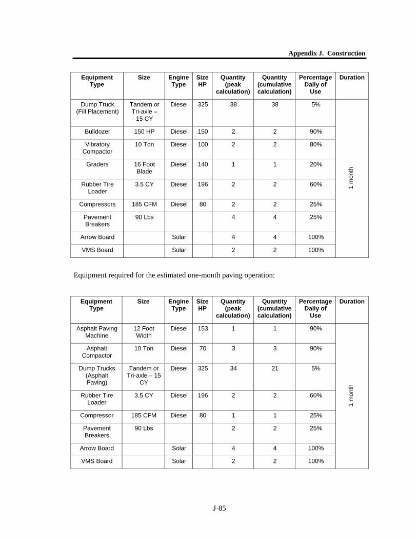
Appendix J. Construction
J-85
Equipment required for the estimated one-month paving operation:
Equipment Type
Size Engine Type
Size HP
Quantity (peak
calculation)
Quantity (cumulative calculation)
Percentage Daily of
Use
Duration
Dump Truck (Fill Placement)
Tandem or Tri-axle –
15 CY
Diesel 325 38 38 5%
Bulldozer 150 HP Diesel 150 2 2 90%
Vibratory Compactor
10 Ton Diesel 100 2 2 80%
Graders 16 Foot Blade
Diesel 140 1 1 20%
Rubber Tire Loader
3.5 CY Diesel 196 2 2 60%
Compressors 185 CFM Diesel 80 2 2 25%
Pavement Breakers
90 Lbs 4 4 25%
Arrow Board Solar 4 4 100%
VMS Board Solar 2 2 100%
1 m
onth
Equipment Type
Size Engine Type
Size HP
Quantity (peak
calculation)
Quantity (cumulative calculation)
Percentage Daily of
Use
Duration
Asphalt Paving Machine
12 Foot Width
Diesel 153 1 1 90%
Asphalt Compactor
10 Ton Diesel 70 3 3 90%
Dump Trucks (Asphalt Paving)
Tandem or Tri-axle – 15
CY
Diesel 325 34 21 5%
Rubber Tire Loader
3.5 CY Diesel 196 2 2 60%
Compressor 185 CFM Diesel 80 1 1 25%
Pavement Breakers
90 Lbs 2 2 25%
Arrow Board Solar 4 4 100%
VMS Board Solar 2 2 100%
1 m
onth
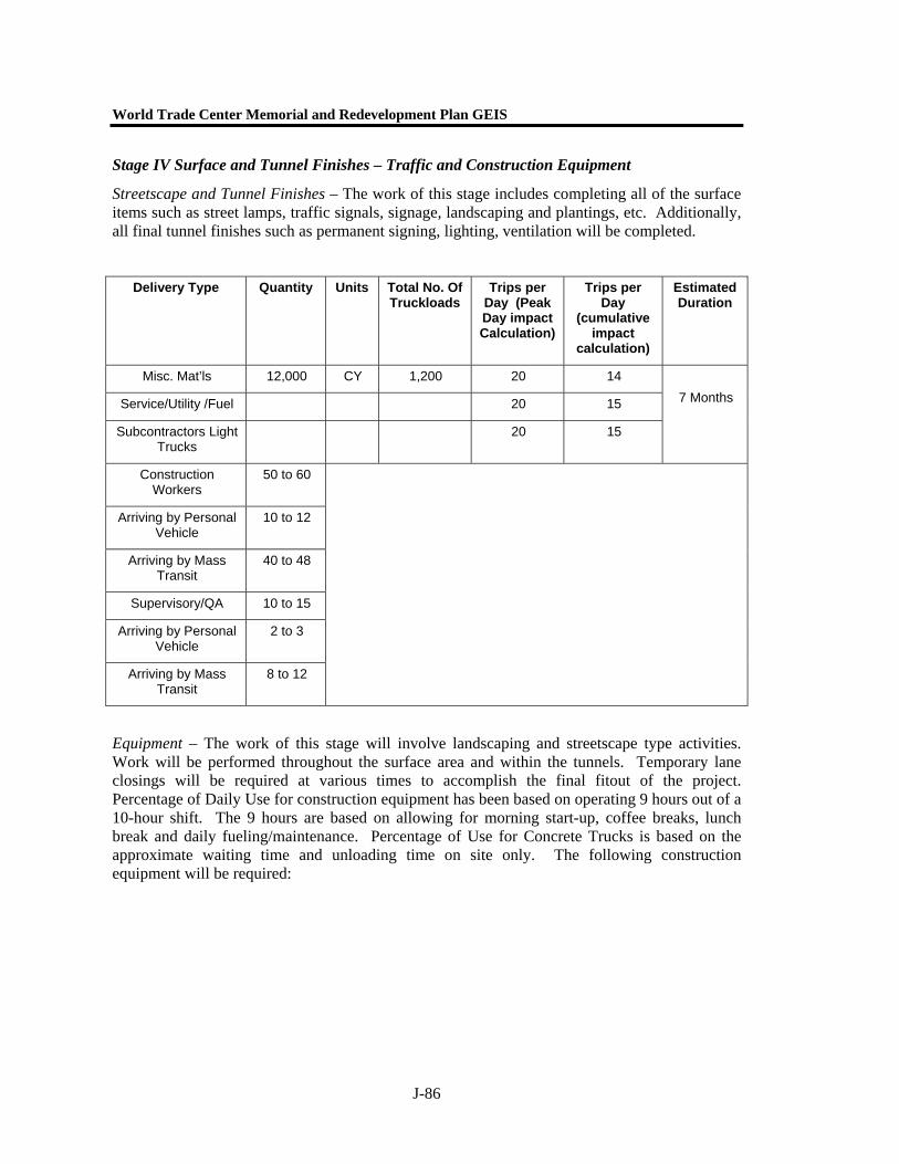
World Trade Center Memorial and Redevelopment Plan GEIS
J-86
Stage IV Surface and Tunnel Finishes – Traffic and Construction Equipment
Streetscape and Tunnel Finishes – The work of this stage includes completing all of the surface items such as street lamps, traffic signals, signage, landscaping and plantings, etc. Additionally, all final tunnel finishes such as permanent signing, lighting, ventilation will be completed.
Equipment – The work of this stage will involve landscaping and streetscape type activities. Work will be performed throughout the surface area and within the tunnels. Temporary lane closings will be required at various times to accomplish the final fitout of the project. Percentage of Daily Use for construction equipment has been based on operating 9 hours out of a 10-hour shift. The 9 hours are based on allowing for morning start-up, coffee breaks, lunch break and daily fueling/maintenance. Percentage of Use for Concrete Trucks is based on the approximate waiting time and unloading time on site only. The following construction equipment will be required:
Delivery Type Quantity Units Total No. Of Truckloads
Trips per Day (Peak Day impact Calculation)
Trips per Day
(cumulative impact
calculation)
Estimated Duration
Misc. Mat’ls 12,000 CY 1,200 20 14
Service/Utility /Fuel 20 15
Subcontractors Light Trucks
20 15
7 Months
Construction Workers
50 to 60
Arriving by Personal Vehicle
10 to 12
Arriving by Mass Transit
40 to 48
Supervisory/QA 10 to 15
Arriving by Personal Vehicle
2 to 3
Arriving by Mass Transit
8 to 12
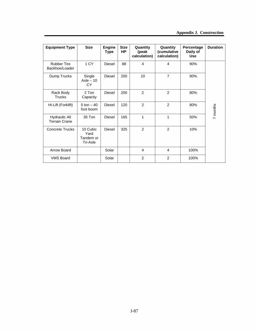
Appendix J. Construction
J-87
Equipment Type Size Engine Type
Size HP
Quantity (peak
calculation)
Quantity (cumulative calculation)
Percentage Daily of
Use
Duration
Rubber Tire Backhoe/Loader
1 CY Diesel 88 4 4 90%
Dump Trucks Single Axle – 10
CY
Diesel 200 10 7 90%
Rack Body Trucks
2 Ton Capacity
Diesel 200 2 2 80%
Hi-Lift (Forklift) 5 ton – 40 foot boom
Diesel 120 2 2 80%
Hydraulic All Terrain Crane
35 Ton Diesel 165 1 1 50%
Concrete Trucks 10 Cubic Yard
Tandem or Tri-Axle
Diesel 325 2 2 10%
Arrow Board Solar 4 4 100%
VMS Board Solar 2 2 100%
7 m
onth
s

World Trade Center Memorial and Redevelopment Plan GEIS
J-88
FULTON STREET TRANSIT CENTER
CONSTRUCTION METHODS AND IMPACTS
Tunneling for Underpasses – Traffic and Construction Equipment
Tunneling operations will be required to construct concourse beneath the N/R Line at Church Street and the 4/5 Line beneath Broadway. The tunneling operations will be performed from within the existing tunnels (grouting operations) and from the cut and cover excavations for the Transit Center and the Dey Street Concourse. It is assumed here that grouting equipment will access the tunneling locations from within the existing subway tunnels. Spoils from tunneling operations will be removed through the cut and cover excavations to street level for hauling from the site. Grouting and underpinning operations will most likely be performed overnight and on weekends to minimize disruption to transit operations. No street closings are anticipated for this work to take place since the grouting will be performed within the subway tunnels and the tunneling work will be performed from the cut and cover excavation of Dey Street and the open excavation for the Transit Center.
4/5 underpasses
Delivery Type Quantity Units Total No. Of Truckloads
Trips per Day (Peak Day impact Calculation)
Trips per Day
(cumulative impact
calculation)
Estimated Duration
Spoil Removal 7,000 CY 470 8 6.5
Underpinning 1,000 Tons 50 2 0.7
Concrete / Steel 1,000 CY 100 4 1.4
Service/Utility /Fuel 4 2
Subcontractors Light Trucks
10 6
6 Months
Construction Workers
15 to 20
Arriving by Personal Vehicle
3 to 4
Arriving by Mass Transit
12 to 16
Supervisory/QA 3 to 8
Arriving by Personal Vehicle
1 to 2
Arriving by Mass Transit
2 to 6
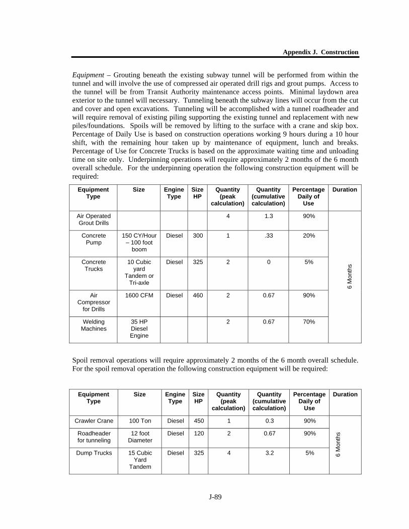
Appendix J. Construction
J-89
Equipment – Grouting beneath the existing subway tunnel will be performed from within the tunnel and will involve the use of compressed air operated drill rigs and grout pumps. Access to the tunnel will be from Transit Authority maintenance access points. Minimal laydown area exterior to the tunnel will necessary. Tunneling beneath the subway lines will occur from the cut and cover and open excavations. Tunneling will be accomplished with a tunnel roadheader and will require removal of existing piling supporting the existing tunnel and replacement with new piles/foundations. Spoils will be removed by lifting to the surface with a crane and skip box. Percentage of Daily Use is based on construction operations working 9 hours during a 10 hour shift, with the remaining hour taken up by maintenance of equipment, lunch and breaks. Percentage of Use for Concrete Trucks is based on the approximate waiting time and unloading time on site only. Underpinning operations will require approximately 2 months of the 6 month overall schedule. For the underpinning operation the following construction equipment will be required:
Spoil removal operations will require approximately 2 months of the 6 month overall schedule. For the spoil removal operation the following construction equipment will be required:
Equipment Type
Size Engine Type
Size HP
Quantity (peak
calculation)
Quantity (cumulative calculation)
Percentage Daily of
Use
Duration
Air Operated Grout Drills
4 1.3 90%
Concrete Pump
150 CY/Hour – 100 foot
boom
Diesel 300 1 .33 20%
Concrete Trucks
10 Cubic yard
Tandem or Tri-axle
Diesel 325 2 0 5%
Air Compressor
for Drills
1600 CFM Diesel 460 2 0.67 90%
Welding Machines
35 HP Diesel Engine
2 0.67 70%
6 M
onth
s
Equipment Type
Size Engine Type
Size HP
Quantity (peak
calculation)
Quantity (cumulative calculation)
Percentage Daily of
Use
Duration
Crawler Crane 100 Ton Diesel 450 1 0.3 90%
Roadheader for tunneling
12 foot Diameter
Diesel 120 2 0.67 90%
Dump Trucks 15 Cubic Yard
Tandem
Diesel 325 4 3.2 5% 6 M
onth
s
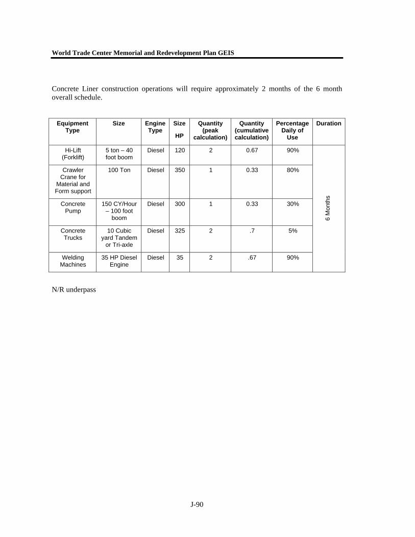
World Trade Center Memorial and Redevelopment Plan GEIS
J-90
Concrete Liner construction operations will require approximately 2 months of the 6 month overall schedule.
N/R underpass
Equipment Type
Size Engine Type
Size
HP
Quantity (peak
calculation)
Quantity (cumulative calculation)
Percentage Daily of
Use
Duration
Hi-Lift (Forklift)
5 ton – 40 foot boom
Diesel 120 2 0.67 90%
Crawler Crane for
Material and Form support
100 Ton Diesel 350 1 0.33 80%
Concrete Pump
150 CY/Hour – 100 foot
boom
Diesel 300 1 0.33 30%
Concrete Trucks
10 Cubic yard Tandem
or Tri-axle
Diesel 325 2 .7 5%
Welding Machines
35 HP Diesel Engine
Diesel 35 2 .67 90%
6 M
onth
s
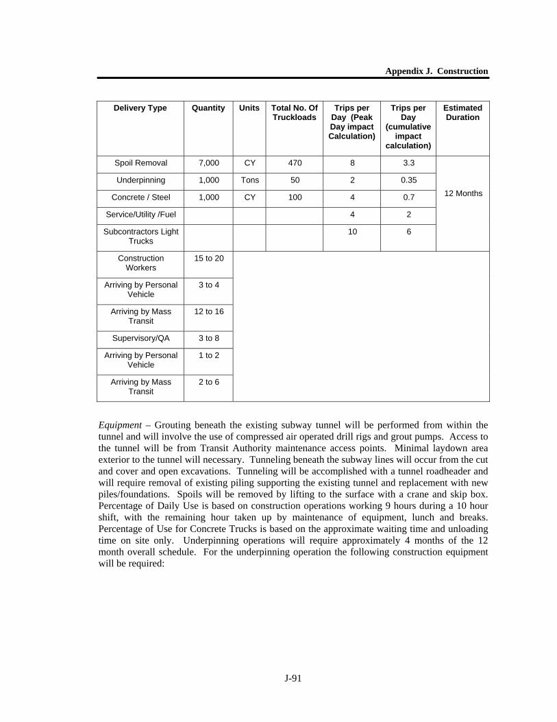
Appendix J. Construction
J-91
Equipment – Grouting beneath the existing subway tunnel will be performed from within the tunnel and will involve the use of compressed air operated drill rigs and grout pumps. Access to the tunnel will be from Transit Authority maintenance access points. Minimal laydown area exterior to the tunnel will necessary. Tunneling beneath the subway lines will occur from the cut and cover and open excavations. Tunneling will be accomplished with a tunnel roadheader and will require removal of existing piling supporting the existing tunnel and replacement with new piles/foundations. Spoils will be removed by lifting to the surface with a crane and skip box. Percentage of Daily Use is based on construction operations working 9 hours during a 10 hour shift, with the remaining hour taken up by maintenance of equipment, lunch and breaks. Percentage of Use for Concrete Trucks is based on the approximate waiting time and unloading time on site only. Underpinning operations will require approximately 4 months of the 12 month overall schedule. For the underpinning operation the following construction equipment will be required:
Delivery Type Quantity Units Total No. Of Truckloads
Trips per Day (Peak Day impact Calculation)
Trips per Day
(cumulative impact
calculation)
Estimated Duration
Spoil Removal 7,000 CY 470 8 3.3
Underpinning 1,000 Tons 50 2 0.35
Concrete / Steel 1,000 CY 100 4 0.7
Service/Utility /Fuel 4 2
Subcontractors Light Trucks
10 6
12 Months
Construction Workers
15 to 20
Arriving by Personal Vehicle
3 to 4
Arriving by Mass Transit
12 to 16
Supervisory/QA 3 to 8
Arriving by Personal Vehicle
1 to 2
Arriving by Mass Transit
2 to 6
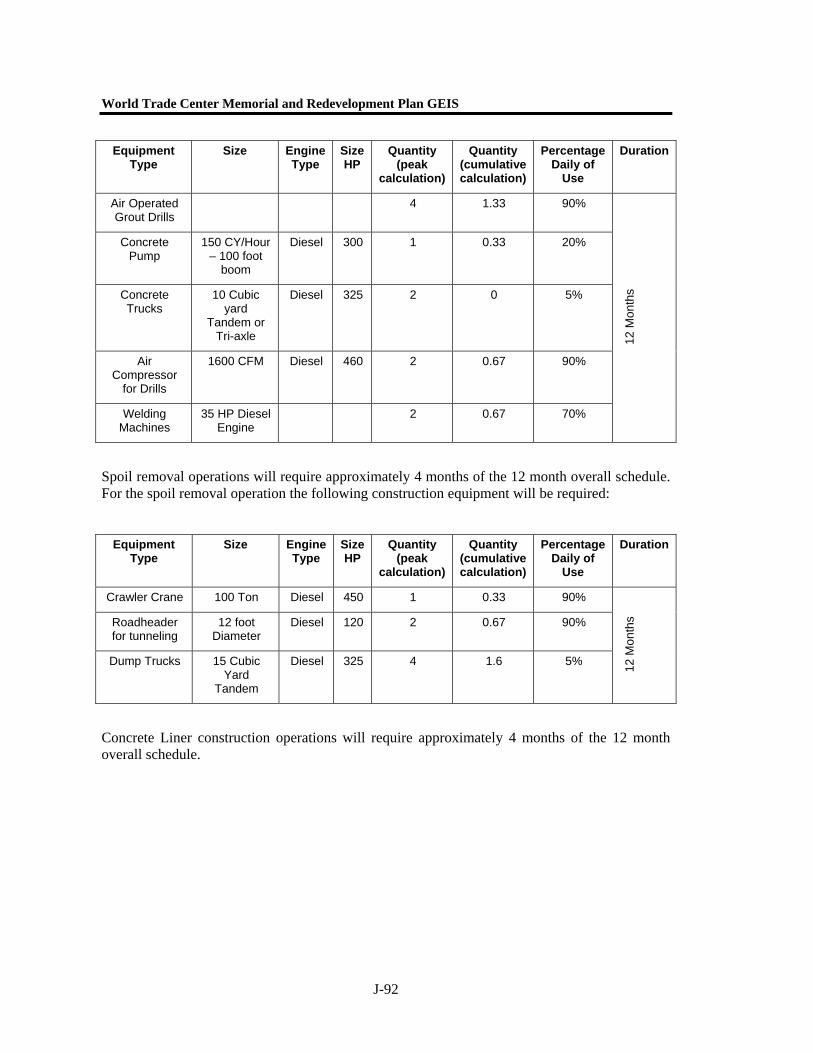
World Trade Center Memorial and Redevelopment Plan GEIS
J-92
Spoil removal operations will require approximately 4 months of the 12 month overall schedule. For the spoil removal operation the following construction equipment will be required:
Concrete Liner construction operations will require approximately 4 months of the 12 month overall schedule.
Equipment Type
Size Engine Type
Size HP
Quantity (peak
calculation)
Quantity (cumulative calculation)
Percentage Daily of
Use
Duration
Air Operated Grout Drills
4 1.33 90%
Concrete Pump
150 CY/Hour – 100 foot
boom
Diesel 300 1 0.33 20%
Concrete Trucks
10 Cubic yard
Tandem or Tri-axle
Diesel 325 2 0 5%
Air Compressor
for Drills
1600 CFM Diesel 460 2 0.67 90%
Welding Machines
35 HP Diesel Engine
2 0.67 70%
12 M
onth
s
Equipment Type
Size Engine Type
Size HP
Quantity (peak
calculation)
Quantity (cumulative calculation)
Percentage Daily of
Use
Duration
Crawler Crane 100 Ton Diesel 450 1 0.33 90%
Roadheader for tunneling
12 foot Diameter
Diesel 120 2 0.67 90%
Dump Trucks 15 Cubic Yard
Tandem
Diesel 325 4 1.6 5% 12 M
onth
s
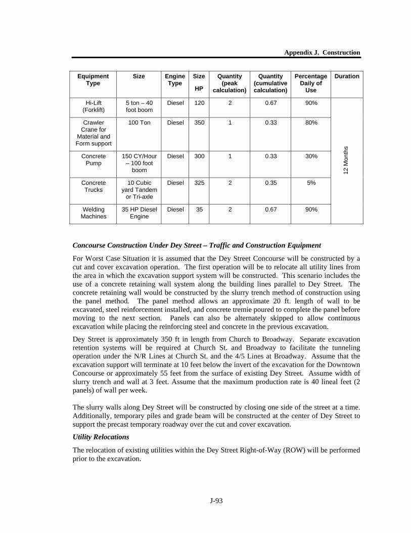
Appendix J. Construction
J-93
Concourse Construction Under Dey Street – Traffic and Construction Equipment
For Worst Case Situation it is assumed that the Dey Street Concourse will be constructed by a cut and cover excavation operation. The first operation will be to relocate all utility lines from the area in which the excavation support system will be constructed. This scenario includes the use of a concrete retaining wall system along the building lines parallel to Dey Street. The concrete retaining wall would be constructed by the slurry trench method of construction using the panel method. The panel method allows an approximate 20 ft. length of wall to be excavated, steel reinforcement installed, and concrete tremie poured to complete the panel before moving to the next section. Panels can also be alternately skipped to allow continuous excavation while placing the reinforcing steel and concrete in the previous excavation.
Dey Street is approximately 350 ft in length from Church to Broadway. Separate excavation retention systems will be required at Church St. and Broadway to facilitate the tunneling operation under the N/R Lines at Church St. and the 4/5 Lines at Broadway. Assume that the excavation support will terminate at 10 feet below the invert of the excavation for the Downtown Concourse or approximately 55 feet from the surface of existing Dey Street. Assume width of slurry trench and wall at 3 feet. Assume that the maximum production rate is 40 lineal feet (2 panels) of wall per week. The slurry walls along Dey Street will be constructed by closing one side of the street at a time. Additionally, temporary piles and grade beam will be constructed at the center of Dey Street to support the precast temporary roadway over the cut and cover excavation.
Utility Relocations
The relocation of existing utilities within the Dey Street Right-of-Way (ROW) will be performed prior to the excavation.
Equipment Type
Size Engine Type
Size
HP
Quantity (peak
calculation)
Quantity (cumulative calculation)
Percentage Daily of
Use
Duration
Hi-Lift (Forklift)
5 ton – 40 foot boom
Diesel 120 2 0.67 90%
Crawler Crane for
Material and Form support
100 Ton Diesel 350 1 0.33 80%
Concrete Pump
150 CY/Hour – 100 foot
boom
Diesel 300 1 0.33 30%
Concrete Trucks
10 Cubic yard Tandem
or Tri-axle
Diesel 325 2 0.35 5%
Welding Machines
35 HP Diesel Engine
Diesel 35 2 0.67 90%
12 M
onth
s
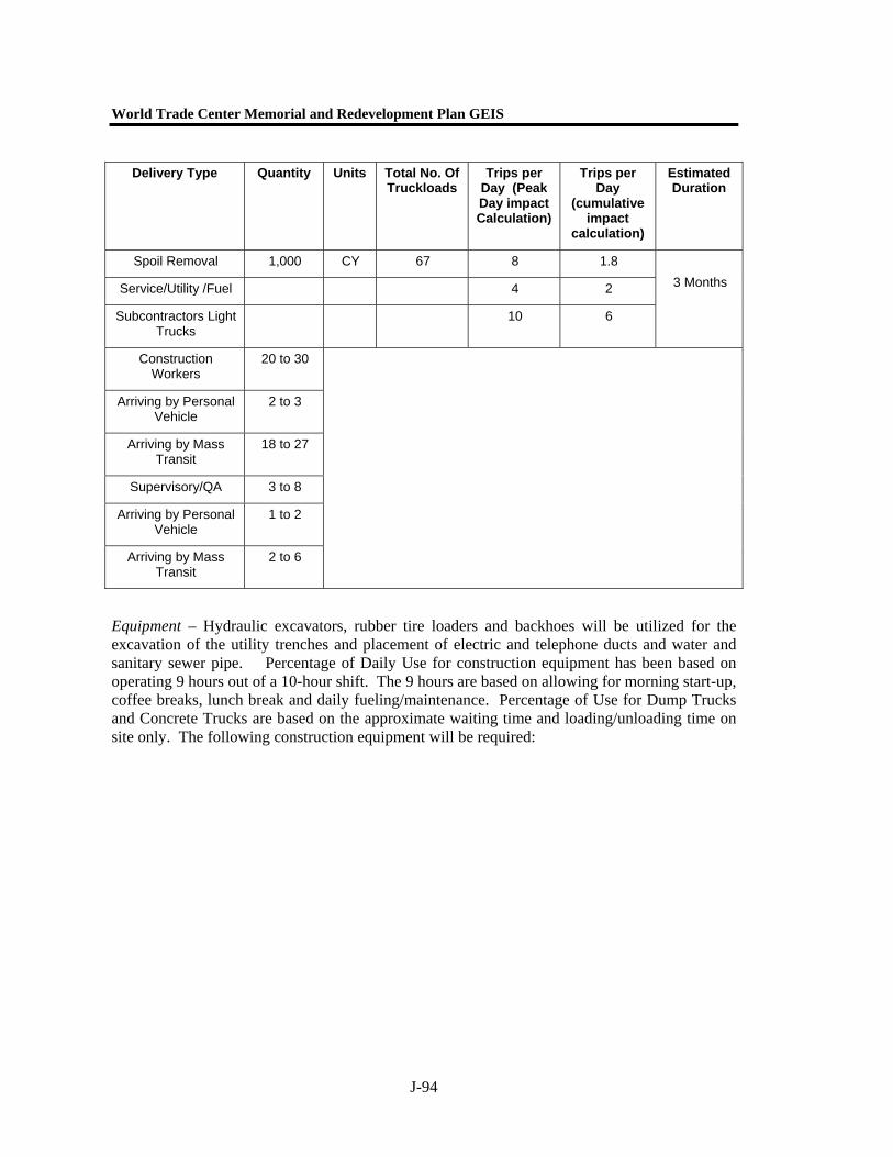
World Trade Center Memorial and Redevelopment Plan GEIS
J-94
Equipment – Hydraulic excavators, rubber tire loaders and backhoes will be utilized for the excavation of the utility trenches and placement of electric and telephone ducts and water and sanitary sewer pipe. Percentage of Daily Use for construction equipment has been based on operating 9 hours out of a 10-hour shift. The 9 hours are based on allowing for morning start-up, coffee breaks, lunch break and daily fueling/maintenance. Percentage of Use for Dump Trucks and Concrete Trucks are based on the approximate waiting time and loading/unloading time on site only. The following construction equipment will be required:
Delivery Type Quantity Units Total No. Of Truckloads
Trips per Day (Peak Day impact Calculation)
Trips per Day
(cumulative impact
calculation)
Estimated Duration
Spoil Removal 1,000 CY 67 8 1.8
Service/Utility /Fuel 4 2
Subcontractors Light Trucks
10 6
3 Months
Construction Workers
20 to 30
Arriving by Personal Vehicle
2 to 3
Arriving by Mass Transit
18 to 27
Supervisory/QA 3 to 8
Arriving by Personal Vehicle
1 to 2
Arriving by Mass Transit
2 to 6

Appendix J. Construction
J-95
Slurry Wall – Construction will consist of closing half of Dey Street at one time for the excavation and placement of the slurry wall. Prior to slurry wall construction the utilities within the closed portion of Dey Street will be temporarily relocated. A single lane closing along Broadway or Church Street will be required to stage materials and support equipment since excavation of the Transit Center site is scheduled concurrently.
Equipment Type
Size Engine Type
Size HP
Quantity (peak
calculation)
Quantity (cumulative calculation)
Percentage Daily of
Use
Duration
Hydraulic Excavator
1.5 CY Diesel 138 2 2 90%
Rubber Tire Loader
3.5 CY Diesel 196 2 2 90%
Rubber Tire Backhoe/Loader
1.25 CY Diesel 88 4 4 90%
Dump Trucks 15 CY Tandem or Tri-axle
Diesel 325 4 0.9 5%
Pumps for Dewatering
4” Gasoline Powered
Gasoline 16 2 2 90%
Compressor 185 CFM Diesel 80 2 2 80%
Pavement Breakers
90 Lbs 2 2 80%
Generators Gasoline Powered
Gasoline 12 2 2 90%
Air hammers (ringing and
ripping)
Gasoline Gasoline 2 2 25%
3 M
onth
s
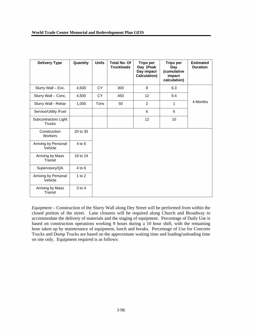
World Trade Center Memorial and Redevelopment Plan GEIS
J-96
Equipment – Construction of the Slurry Wall along Dey Street will be performed from within the closed portion of the street. Lane closures will be required along Church and Broadway to accommodate the delivery of materials and the staging of equipment. Percentage of Daily Use is based on construction operations working 9 hours during a 10 hour shift, with the remaining hour taken up by maintenance of equipment, lunch and breaks. Percentage of Use for Concrete Trucks and Dump Trucks are based on the approximate waiting time and loading/unloading time on site only. Equipment required is as follows:
Delivery Type Quantity Units Total No. Of Truckloads
Trips per Day (Peak Day impact Calculation)
Trips per Day
(cumulative impact
calculation)
Estimated Duration
Slurry Wall – Exc. 4,500 CY 300 8 6.3
Slurry Wall – Conc. 4,500 CY 450 12 9.4
Slurry Wall - Rebar 1,000 Tons 50 2 1
Service/Utility /Fuel 6 6
Subcontractors Light Trucks
12 10
4 Months
Construction Workers
20 to 30
Arriving by Personal Vehicle
4 to 6
Arriving by Mass Transit
16 to 24
Supervisory/QA 4 to 6
Arriving by Personal Vehicle
1 to 2
Arriving by Mass Transit
3 to 4
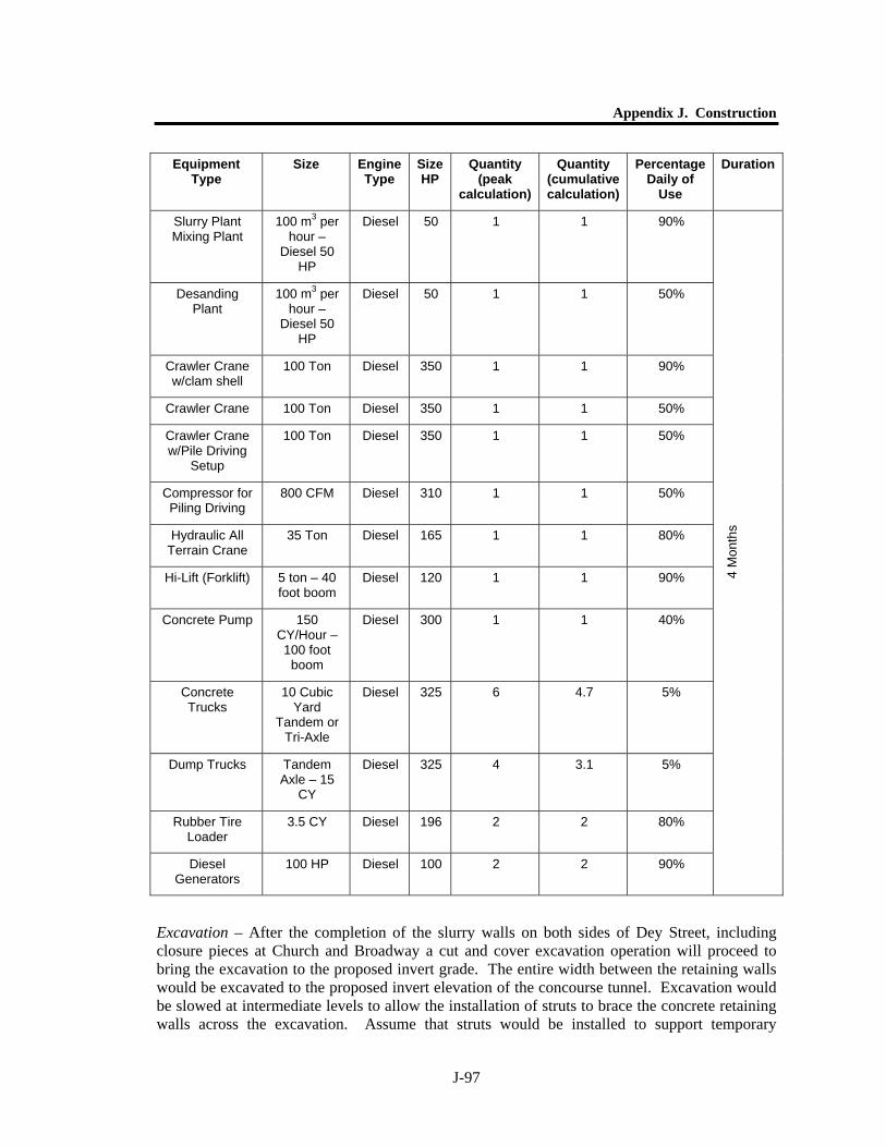
Appendix J. Construction
J-97
Excavation – After the completion of the slurry walls on both sides of Dey Street, including closure pieces at Church and Broadway a cut and cover excavation operation will proceed to bring the excavation to the proposed invert grade. The entire width between the retaining walls would be excavated to the proposed invert elevation of the concourse tunnel. Excavation would be slowed at intermediate levels to allow the installation of struts to brace the concrete retaining walls across the excavation. Assume that struts would be installed to support temporary
Equipment Type
Size Engine Type
Size HP
Quantity (peak
calculation)
Quantity (cumulative calculation)
Percentage Daily of
Use
Duration
Slurry Plant Mixing Plant
100 m3 per hour –
Diesel 50 HP
Diesel 50 1 1 90%
Desanding Plant
100 m3 per hour –
Diesel 50 HP
Diesel 50 1 1 50%
Crawler Crane w/clam shell
100 Ton Diesel 350 1 1 90%
Crawler Crane 100 Ton Diesel 350 1 1 50%
Crawler Crane w/Pile Driving
Setup
100 Ton Diesel 350 1 1 50%
Compressor for Piling Driving
800 CFM Diesel 310 1 1 50%
Hydraulic All Terrain Crane
35 Ton Diesel 165 1 1 80%
Hi-Lift (Forklift) 5 ton – 40 foot boom
Diesel 120 1 1 90%
Concrete Pump 150 CY/Hour – 100 foot boom
Diesel 300 1 1 40%
Concrete Trucks
10 Cubic Yard
Tandem or Tri-Axle
Diesel 325 6 4.7 5%
Dump Trucks Tandem Axle – 15
CY
Diesel 325 4 3.1 5%
Rubber Tire Loader
3.5 CY Diesel 196 2 2 80%
Diesel Generators
100 HP Diesel 100 2 2 90%
4 M
onth
s
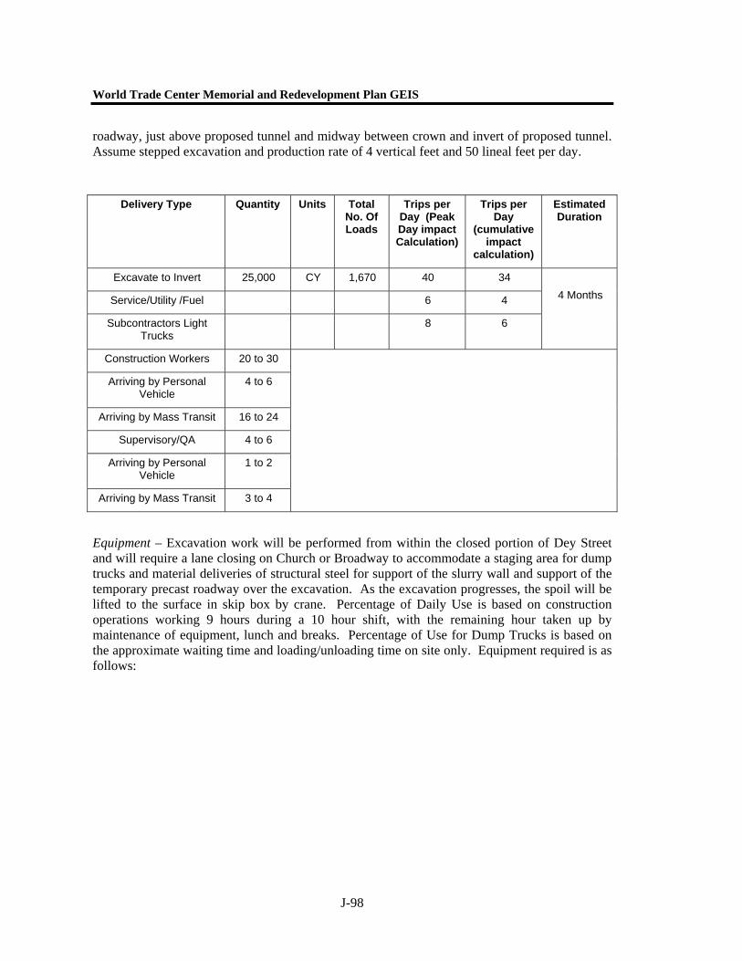
World Trade Center Memorial and Redevelopment Plan GEIS
J-98
roadway, just above proposed tunnel and midway between crown and invert of proposed tunnel. Assume stepped excavation and production rate of 4 vertical feet and 50 lineal feet per day.
Equipment – Excavation work will be performed from within the closed portion of Dey Street and will require a lane closing on Church or Broadway to accommodate a staging area for dump trucks and material deliveries of structural steel for support of the slurry wall and support of the temporary precast roadway over the excavation. As the excavation progresses, the spoil will be lifted to the surface in skip box by crane. Percentage of Daily Use is based on construction operations working 9 hours during a 10 hour shift, with the remaining hour taken up by maintenance of equipment, lunch and breaks. Percentage of Use for Dump Trucks is based on the approximate waiting time and loading/unloading time on site only. Equipment required is as follows:
Delivery Type
Quantity Units Total No. Of Loads
Trips per Day (Peak Day impact Calculation)
Trips per Day
(cumulative impact
calculation)
Estimated Duration
Excavate to Invert 25,000 CY 1,670 40 34
Service/Utility /Fuel 6 4
Subcontractors Light Trucks
8 6
4 Months
Construction Workers 20 to 30
Arriving by Personal Vehicle
4 to 6
Arriving by Mass Transit 16 to 24
Supervisory/QA 4 to 6
Arriving by Personal Vehicle
1 to 2
Arriving by Mass Transit 3 to 4
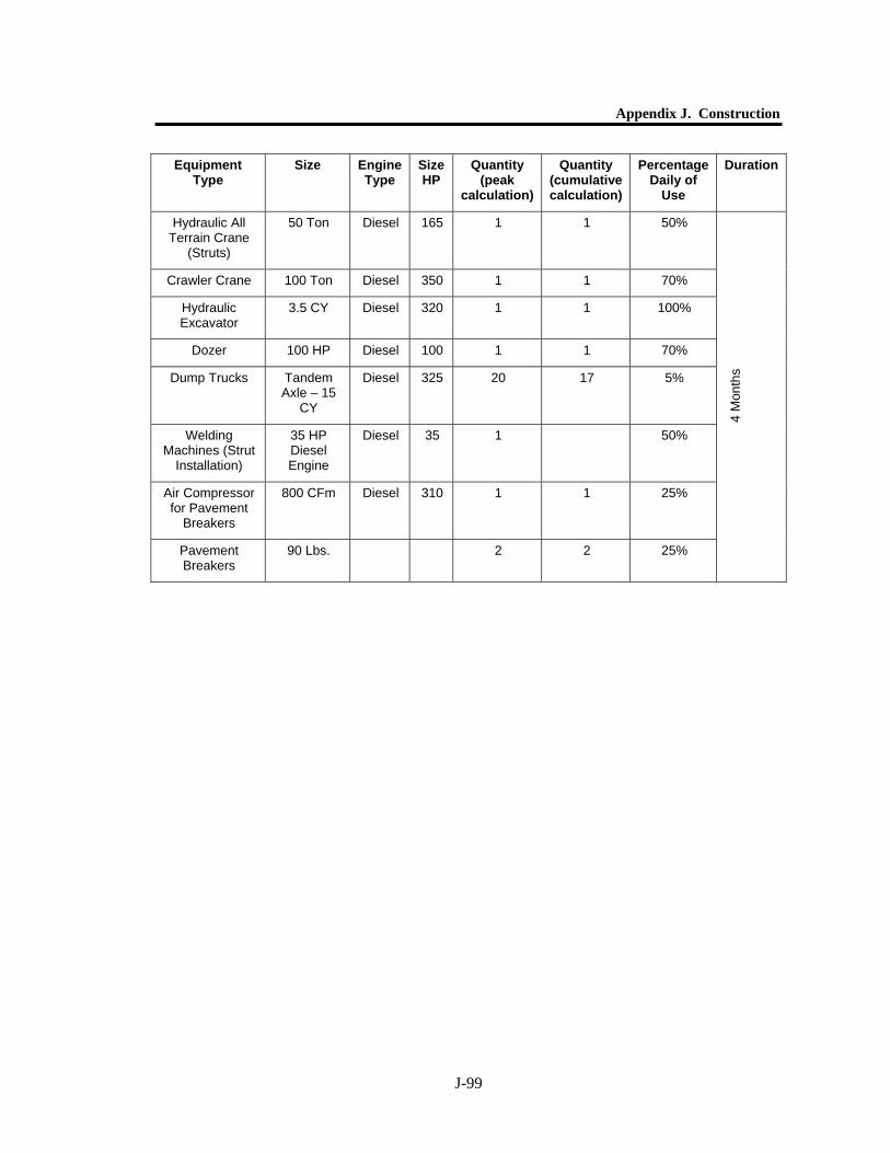
Appendix J. Construction
J-99
Equipment Type
Size Engine Type
Size HP
Quantity (peak
calculation)
Quantity (cumulative calculation)
Percentage Daily of
Use
Duration
Hydraulic All Terrain Crane
(Struts)
50 Ton Diesel 165 1 1 50%
Crawler Crane 100 Ton Diesel 350 1 1 70%
Hydraulic Excavator
3.5 CY Diesel 320 1 1 100%
Dozer 100 HP Diesel 100 1 1 70%
Dump Trucks Tandem Axle – 15
CY
Diesel 325 20 17 5%
Welding Machines (Strut
Installation)
35 HP Diesel Engine
Diesel 35 1 50%
Air Compressor for Pavement
Breakers
800 CFm Diesel 310 1 1 25%
Pavement Breakers
90 Lbs. 2 2 25%
4 M
onth
s
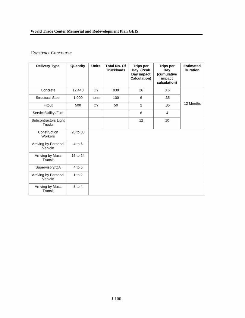
World Trade Center Memorial and Redevelopment Plan GEIS
J-100
Construct Concourse
Delivery Type Quantity Units Total No. Of Truckloads
Trips per Day (Peak Day impact Calculation)
Trips per Day
(cumulative impact
calculation)
Estimated Duration
Concrete 12,440 CY 830 26 8.6
Structural Steel 1,000 tons 100 6 .35
Fitout 500 CY 50 2 .35
Service/Utility /Fuel 6 4
Subcontractors Light Trucks
12 10
12 Months
Construction Workers
20 to 30
Arriving by Personal Vehicle
4 to 6
Arriving by Mass Transit
16 to 24
Supervisory/QA 4 to 6
Arriving by Personal Vehicle
1 to 2
Arriving by Mass Transit
3 to 4
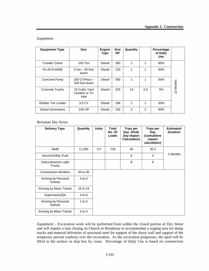
Appendix J. Construction
J-101
Equipment
Reinstate Dey Street
Equipment – Excavation work will be performed from within the closed portion of Dey Street and will require a lane closing on Church or Broadway to accommodate a staging area for dump trucks and material deliveries of structural steel for support of the slurry wall and support of the temporary precast roadway over the excavation. As the excavation progresses, the spoil will be lifted to the surface in skip box by crane. Percentage of Daily Use is based on construction
Equipment Type Size Engine Type
Size HP
Quantity Percentage of Daily
Use
Crawler Crane 100 Ton Diesel 350 1 1 90%
Hi-Lift (Forklift) 5 ton – 40 foot boom
Diesel 120 1 1 90%
Concrete Pump 150 CY/Hour – 100 foot boom
Diesel 300 1 1 50%
Concrete Trucks 10 Cubic Yard Tandem or Tri-
Axle
Diesel 325 13 4.3 5%
Rubber Tire Loader 3.5 CY Diesel 196 1 1 50%
Diesel Generators 100 HP Diesel 100 2 2 90%
12 M
onth
s
Delivery Type
Quantity Units Total No. Of Loads
Trips per Day (Peak Day impact Calculation)
Trips per Day
(cumulative impact
calculation)
Estimated Duration
Refill 11,000 CY 730 40 30.4
Service/Utility /Fuel 6 4
Subcontractors Light Trucks
8 6
2 Months
Construction Workers 20 to 30
Arriving by Personal Vehicle
4 to 6
Arriving by Mass Transit 16 to 24
Supervisory/QA 4 to 6
Arriving by Personal Vehicle
1 to 2
Arriving by Mass Transit 3 to 4
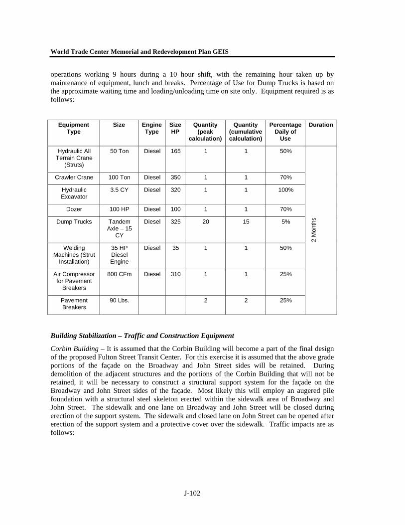
World Trade Center Memorial and Redevelopment Plan GEIS
J-102
operations working 9 hours during a 10 hour shift, with the remaining hour taken up by maintenance of equipment, lunch and breaks. Percentage of Use for Dump Trucks is based on the approximate waiting time and loading/unloading time on site only. Equipment required is as follows:
Building Stabilization – Traffic and Construction Equipment
Corbin Building – It is assumed that the Corbin Building will become a part of the final design of the proposed Fulton Street Transit Center. For this exercise it is assumed that the above grade portions of the façade on the Broadway and John Street sides will be retained. During demolition of the adjacent structures and the portions of the Corbin Building that will not be retained, it will be necessary to construct a structural support system for the façade on the Broadway and John Street sides of the façade. Most likely this will employ an augered pile foundation with a structural steel skeleton erected within the sidewalk area of Broadway and John Street. The sidewalk and one lane on Broadway and John Street will be closed during erection of the support system. The sidewalk and closed lane on John Street can be opened after erection of the support system and a protective cover over the sidewalk. Traffic impacts are as follows:
Equipment Type
Size Engine Type
Size HP
Quantity (peak
calculation)
Quantity (cumulative calculation)
Percentage Daily of
Use
Duration
Hydraulic All Terrain Crane
(Struts)
50 Ton Diesel 165 1 1 50%
Crawler Crane 100 Ton Diesel 350 1 1 70%
Hydraulic Excavator
3.5 CY Diesel 320 1 1 100%
Dozer 100 HP Diesel 100 1 1 70%
Dump Trucks Tandem Axle – 15
CY
Diesel 325 20 15 5%
Welding Machines (Strut
Installation)
35 HP Diesel Engine
Diesel 35 1 1 50%
Air Compressor for Pavement
Breakers
800 CFm Diesel 310 1 1 25%
Pavement Breakers
90 Lbs. 2 2 25%
2 M
onth
s
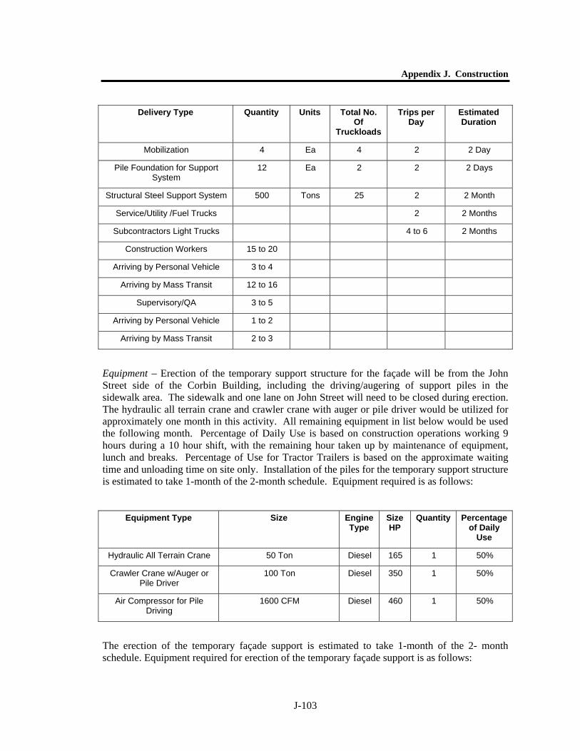
Appendix J. Construction
J-103
Equipment – Erection of the temporary support structure for the façade will be from the John Street side of the Corbin Building, including the driving/augering of support piles in the sidewalk area. The sidewalk and one lane on John Street will need to be closed during erection. The hydraulic all terrain crane and crawler crane with auger or pile driver would be utilized for approximately one month in this activity. All remaining equipment in list below would be used the following month. Percentage of Daily Use is based on construction operations working 9 hours during a 10 hour shift, with the remaining hour taken up by maintenance of equipment, lunch and breaks. Percentage of Use for Tractor Trailers is based on the approximate waiting time and unloading time on site only. Installation of the piles for the temporary support structure is estimated to take 1-month of the 2-month schedule. Equipment required is as follows:
The erection of the temporary façade support is estimated to take 1-month of the 2- month schedule. Equipment required for erection of the temporary façade support is as follows:
Delivery Type Quantity Units Total No. Of
Truckloads
Trips per Day
Estimated Duration
Mobilization 4 Ea 4 2 2 Day
Pile Foundation for Support System
12 Ea 2 2 2 Days
Structural Steel Support System 500 Tons 25 2 2 Month
Service/Utility /Fuel Trucks 2 2 Months
Subcontractors Light Trucks 4 to 6 2 Months
Construction Workers 15 to 20
Arriving by Personal Vehicle 3 to 4
Arriving by Mass Transit 12 to 16
Supervisory/QA 3 to 5
Arriving by Personal Vehicle 1 to 2
Arriving by Mass Transit 2 to 3
Equipment Type Size Engine Type
Size HP
Quantity Percentage of Daily
Use
Hydraulic All Terrain Crane 50 Ton Diesel 165 1 50%
Crawler Crane w/Auger or Pile Driver
100 Ton Diesel 350 1 50%
Air Compressor for Pile Driving
1600 CFM Diesel 460 1 50%

World Trade Center Memorial and Redevelopment Plan GEIS
J-104
Transit Center Construction – Traffic and Construction Equipment
Demolition of Existing Buildings (194-204 Broadway,)– All buildings within the footprint of the proposed Transit Center (194-204 Broadway) will be demolished to grade and the basements removed and the site made level for the installation of a slurry wall and other earth retention systems to support the surrounding streets and buildings during excavation for the Transit Center. The one to three story buildings will be demolished first with the 12-story building demolished floor-by-floor next. The area will then be used as a staging area for activities within the Dey Street right-of-way and concourse until construction of the Dey Street Head (Entrance) House. The Corbin Building will have the interior floors and rear walls removed after the erection of the temporary support structure for the façade.
Equipment Type Size Engine Type
Size HP
Quantity Percentage of Daily
Use
Crawler Crane 200 Ton Diesel 450 1 90%
Hi-Lift(Forklift) 5 ton – 40 foot boom Diesel 120 1 90%
Tractor Trailer Tandem Axle Tractor w/45 FT Trailer
Diesel 325 2 1%
Welding Machine 35 HP Diesel Engine Diesel 35 1 90%
Air Compressor for Impact Wrenches
800 CFM Diesel 310 1 90%
Impact Wrenches 1” Socket Drive 4 90%
Welding Machine 35 HP Diesel Engine Diesel 35 1 90%
Delivery Type Quantity Units Total No. Of Loads
Trips per Day (Peak Day impact Calculation)
Trips per Day (cumulative
impact calculation)
Estimated Duration per stage
Demolition Debris 1,000 Tons 500 20 13.9
Service/Utility /Fuel Trucks
8 6
Subcontractors Light Trucks
6 4
3 Months
Total Construction Workers
20 to 25
Arriving by Personal Vehicle
4 to 5
Arriving by Mass Transit 16 to 20
Supervisory/QA 3 to 5
Arriving by Personal Vehicle
1 to 2
Arriving by Mass Transit 2 to 3
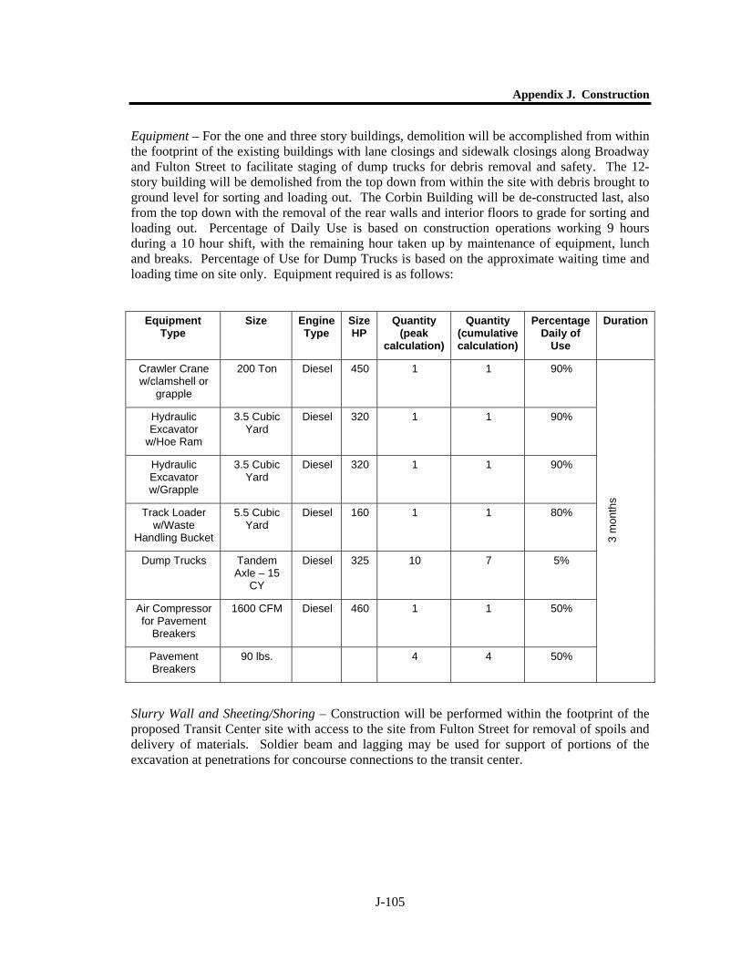
Appendix J. Construction
J-105
Equipment – For the one and three story buildings, demolition will be accomplished from within the footprint of the existing buildings with lane closings and sidewalk closings along Broadway and Fulton Street to facilitate staging of dump trucks for debris removal and safety. The 12-story building will be demolished from the top down from within the site with debris brought to ground level for sorting and loading out. The Corbin Building will be de-constructed last, also from the top down with the removal of the rear walls and interior floors to grade for sorting and loading out. Percentage of Daily Use is based on construction operations working 9 hours during a 10 hour shift, with the remaining hour taken up by maintenance of equipment, lunch and breaks. Percentage of Use for Dump Trucks is based on the approximate waiting time and loading time on site only. Equipment required is as follows:
Slurry Wall and Sheeting/Shoring – Construction will be performed within the footprint of the proposed Transit Center site with access to the site from Fulton Street for removal of spoils and delivery of materials. Soldier beam and lagging may be used for support of portions of the excavation at penetrations for concourse connections to the transit center.
Equipment Type
Size Engine Type
Size HP
Quantity (peak
calculation)
Quantity (cumulative calculation)
Percentage Daily of
Use
Duration
Crawler Crane w/clamshell or
grapple
200 Ton Diesel 450 1 1 90%
Hydraulic Excavator
w/Hoe Ram
3.5 Cubic Yard
Diesel 320 1 1 90%
Hydraulic Excavator w/Grapple
3.5 Cubic Yard
Diesel 320 1 1 90%
Track Loader w/Waste
Handling Bucket
5.5 Cubic Yard
Diesel 160 1 1 80%
Dump Trucks Tandem Axle – 15
CY
Diesel 325 10 7 5%
Air Compressor for Pavement
Breakers
1600 CFM Diesel 460 1 1 50%
Pavement Breakers
90 lbs. 4 4 50%
3 m
onth
s

World Trade Center Memorial and Redevelopment Plan GEIS
J-106
Delivery Type Quantity Units Total No. Of
Truckloads
Trips per Day (Peak Day impact Calculation)
Trips per Day
(cumulative impact
calculation)
Estimated Duration
Slurry Wall – Exc. 3,900 CY 260 8 5.4
Slurry Wall – Conc. 3,900 CY 390 10 8
Slurry Wall - Rebar 1,000 Tons 50 2 1
Service/Utility /Fuel 6 4
Subcontractors Light Trucks
12 10
4 Months
Construction Workers 20 to 30
Arriving by Personal Vehicle
4 to 6
Arriving by Mass Transit 16 to 24
Supervisory/QA 4 to 6
Arriving by Personal Vehicle
1 to 2
Arriving by Mass Transit 3 to 4
Slurry Wall and Sheeting/Shoring Construction Equipment – Construction of the Slurry Wall around the Transit Center site will be performed from within the footprint of the site. Percentage of Daily Use is based on construction operations working 9 hours during a 10 hour shift, with the remaining hour taken up by maintenance of equipment, lunch and breaks. Percentage of Use for Concrete Trucks and Dump Trucks are based on the approximate waiting time and unloading/loading time on site only. Equipment required is as follows.

Appendix J. Construction
J-107
Excavation – After the completion of the earth retention systems, the Transit Center site will be excavated to the proposed grade.
Equipment Type
Size Engine Type
Size HP
Quantity (peak
calculation)
Quantity (cumulative calculation)
Percentage Daily of
Use
Duration
Slurry Plant Mixing Plant
100 m3 per hour –
Diesel 50 HP
Diesel 50 1 1 90%
Desanding Plant
100 m3 per hour –
Diesel 50 HP
Diesel 50 1 1 50%
Crawler Crane w/clam shell
100 Ton Diesel 350 1 1 90%
Crawler Crane 100 Ton Diesel 350 1 1 50%
Crawler Crane w/Piling
Driving Setup
100 Ton Diesel 350 1 1 50%
Hi-Lift (Forklift) 5 ton – 40 foot boom
Diesel 120 1 1 90%
Concrete Pump
150 CY/Hour – 100 foot boom
Diesel 300 1 1 50%
Concrete Trucks
10 Cubic Yard
Tandem or Tri-Axle
Diesel 325 5 4 5%
Dump Trucks Tandem Axle – 15
CY
Diesel 325 4 2.7 5%
Rubber Tire Loader
3.5 CY Diesel 196 1 1 80%
Diesel Generators
100 HP Diesel 100 1 1 90%
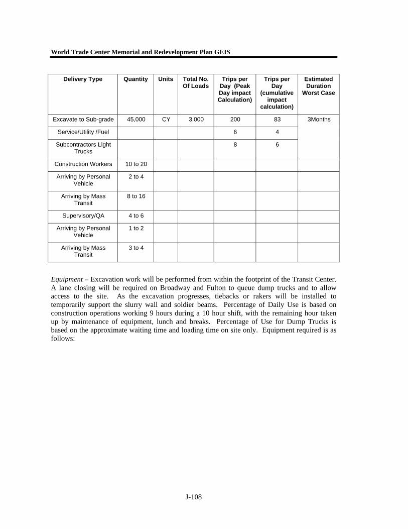
World Trade Center Memorial and Redevelopment Plan GEIS
J-108
Equipment – Excavation work will be performed from within the footprint of the Transit Center. A lane closing will be required on Broadway and Fulton to queue dump trucks and to allow access to the site. As the excavation progresses, tiebacks or rakers will be installed to temporarily support the slurry wall and soldier beams. Percentage of Daily Use is based on construction operations working 9 hours during a 10 hour shift, with the remaining hour taken up by maintenance of equipment, lunch and breaks. Percentage of Use for Dump Trucks is based on the approximate waiting time and loading time on site only. Equipment required is as follows:
Delivery Type
Quantity Units Total No. Of Loads
Trips per Day (Peak Day impact Calculation)
Trips per Day
(cumulative impact
calculation)
Estimated Duration
Worst Case
Excavate to Sub-grade 45,000 CY 3,000 200 83
Service/Utility /Fuel 6 4
Subcontractors Light Trucks
8 6
3Months
Construction Workers 10 to 20
Arriving by Personal Vehicle
2 to 4
Arriving by Mass Transit
8 to 16
Supervisory/QA 4 to 6
Arriving by Personal Vehicle
1 to 2
Arriving by Mass Transit
3 to 4
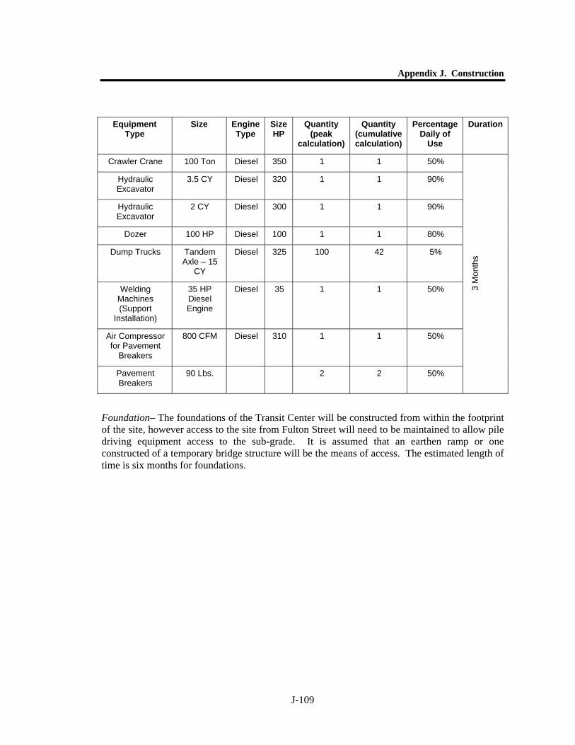
Appendix J. Construction
J-109
Foundation– The foundations of the Transit Center will be constructed from within the footprint of the site, however access to the site from Fulton Street will need to be maintained to allow pile driving equipment access to the sub-grade. It is assumed that an earthen ramp or one constructed of a temporary bridge structure will be the means of access. The estimated length of time is six months for foundations.
Equipment Type
Size Engine Type
Size HP
Quantity (peak
calculation)
Quantity (cumulative calculation)
Percentage Daily of
Use
Duration
Crawler Crane 100 Ton Diesel 350 1 1 50%
Hydraulic Excavator
3.5 CY Diesel 320 1 1 90%
Hydraulic Excavator
2 CY Diesel 300 1 1 90%
Dozer 100 HP Diesel 100 1 1 80%
Dump Trucks Tandem Axle – 15
CY
Diesel 325 100 42 5%
Welding Machines (Support
Installation)
35 HP Diesel Engine
Diesel 35 1 1 50%
Air Compressor for Pavement
Breakers
800 CFM Diesel 310 1 1 50%
Pavement Breakers
90 Lbs. 2 2 50%
3 M
onth
s
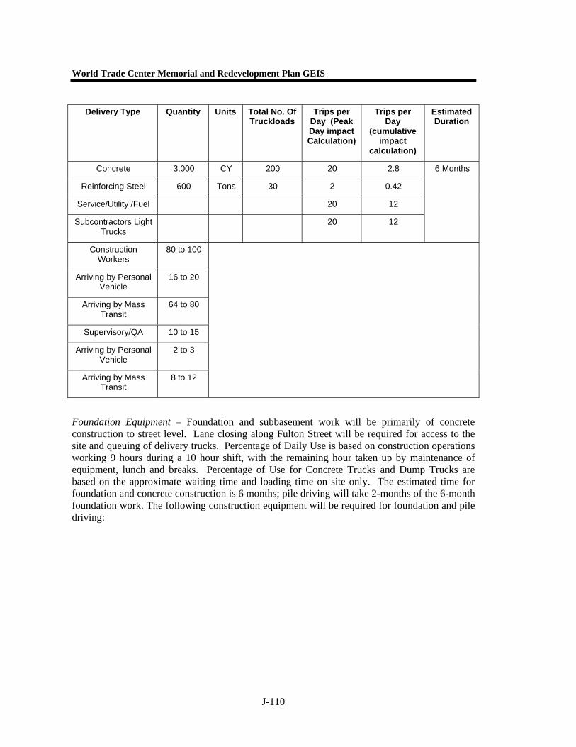
World Trade Center Memorial and Redevelopment Plan GEIS
J-110
Foundation Equipment – Foundation and subbasement work will be primarily of concrete construction to street level. Lane closing along Fulton Street will be required for access to the site and queuing of delivery trucks. Percentage of Daily Use is based on construction operations working 9 hours during a 10 hour shift, with the remaining hour taken up by maintenance of equipment, lunch and breaks. Percentage of Use for Concrete Trucks and Dump Trucks are based on the approximate waiting time and loading time on site only. The estimated time for foundation and concrete construction is 6 months; pile driving will take 2-months of the 6-month foundation work. The following construction equipment will be required for foundation and pile driving:
Delivery Type Quantity Units Total No. Of Truckloads
Trips per Day (Peak Day impact Calculation)
Trips per Day
(cumulative impact
calculation)
Estimated Duration
Concrete 3,000 CY 200 20 2.8
Reinforcing Steel 600 Tons 30 2 0.42
Service/Utility /Fuel 20 12
Subcontractors Light Trucks
20 12
6 Months
Construction Workers
80 to 100
Arriving by Personal Vehicle
16 to 20
Arriving by Mass Transit
64 to 80
Supervisory/QA 10 to 15
Arriving by Personal Vehicle
2 to 3
Arriving by Mass Transit
8 to 12
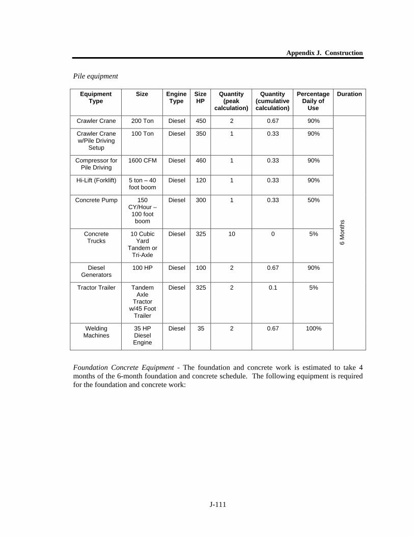
Appendix J. Construction
J-111
Pile equipment
Foundation Concrete Equipment - The foundation and concrete work is estimated to take 4 months of the 6-month foundation and concrete schedule. The following equipment is required for the foundation and concrete work:
Equipment Type
Size Engine Type
Size HP
Quantity (peak
calculation)
Quantity (cumulative calculation)
Percentage Daily of
Use
Duration
Crawler Crane 200 Ton Diesel 450 2 0.67 90%
Crawler Crane w/Pile Driving
Setup
100 Ton Diesel 350 1 0.33 90%
Compressor for Pile Driving
1600 CFM Diesel 460 1 0.33 90%
Hi-Lift (Forklift) 5 ton – 40 foot boom
Diesel 120 1 0.33 90%
Concrete Pump 150 CY/Hour – 100 foot
boom
Diesel 300 1 0.33 50%
Concrete Trucks
10 Cubic Yard
Tandem or Tri-Axle
Diesel 325 10 0 5%
Diesel Generators
100 HP Diesel 100 2 0.67 90%
Tractor Trailer Tandem Axle
Tractor w/45 Foot
Trailer
Diesel 325 2 0.1 5%
Welding Machines
35 HP Diesel Engine
Diesel 35 2 0.67 100%
6 M
onth
s
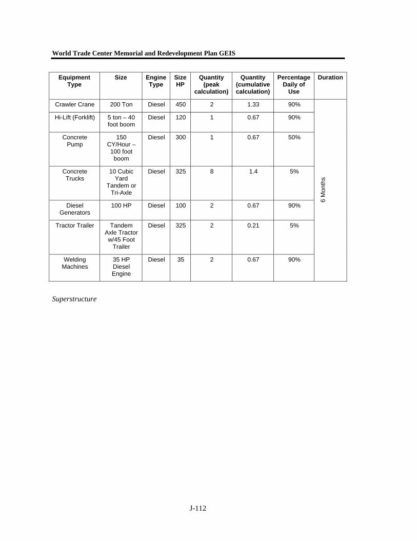
World Trade Center Memorial and Redevelopment Plan GEIS
J-112
Superstructure
Equipment Type
Size Engine Type
Size HP
Quantity (peak
calculation)
Quantity (cumulative calculation)
Percentage Daily of
Use
Duration
Crawler Crane 200 Ton Diesel 450 2 1.33 90%
Hi-Lift (Forklift) 5 ton – 40 foot boom
Diesel 120 1 0.67 90%
Concrete Pump
150 CY/Hour – 100 foot
boom
Diesel 300 1 0.67 50%
Concrete Trucks
10 Cubic Yard
Tandem or Tri-Axle
Diesel 325 8 1.4 5%
Diesel Generators
100 HP Diesel 100 2 0.67 90%
Tractor Trailer Tandem Axle Tractor w/45 Foot
Trailer
Diesel 325 2 0.21 5%
Welding Machines
35 HP Diesel Engine
Diesel 35 2 0.67 90%
6 M
onth
s

Appendix J. Construction
J-113
Superstructure Equipment - The erection of the superstructure and enclosing facade is estimated to take 6-months. The following equipment is required:
Delivery Type Quantity Units Total No. Of Truckloads
Trips per Day (Peak Day impact Calculation)
Trips per Day
(cumulative impact
calculation)
Estimated Duration
Structural Steel 1,500 Tons 75 4 1
Structural Steel – Grand Space
3,000 Tons 150 4 2
Curtain Wall 400 Tons 20 2 0.28
Service/Utility /Fuel 20 12
Subcontractors Light Trucks
20 12
6 Months
Construction Workers
80 to 100
Arriving by Personal Vehicle
16 to 20
Arriving by Mass Transit
64 to 80
Supervisory/QA 10 to 15
Arriving by Personal Vehicle
2 to 3
Arriving by Mass Transit
8 to 12

World Trade Center Memorial and Redevelopment Plan GEIS
J-114
Widening of A/C Mezzanine – Traffic and Construction Equipment
The A/C Mezzanine widening will be accomplished using a sequential cut and cover operation to allow the existing platforms to remain in service during construction. The operation will require a minimum of a lane closing along Fulton Street to accommodate the operation and staging area for equipment and materials. Construction activities include grouting, temporary bracing, demolition and excavation of roadway, slurry wall construction, concrete construction, interior fitout of mezzanine and reconstruction of Fulton Street over the widened mezzanine. Utility Relocations -The relocation of existing utilities within the Fulton Street Right-of-Way (ROW) will be performed prior to the excavation
Equipment Type
Size Engine Type
Size HP
Quantity (peak
calculation)
Quantity (cumulative calculation)
Percentage Daily of
Use
Duration
Crawler Crane 200 Ton Diesel 450 2 2 100%
Hi-Lift (Forklift) 5 ton – 40 foot boom
Diesel 120 1 1 100%
Concrete Pump 150 CY/Hour – 100 foot
boom
Diesel 300 1 1 50%
Concrete Trucks
10 Cubic Yard
Tandem or Tri-Axle
Diesel 325 8 2 5%
Diesel Generators
100 HP Diesel 100 2 2 100%
Tractor Trailer Tandem Axle Tractor w/45 Foot
Trailer
Diesel 325 5 2 5%
Welding Machines
35 HP Diesel Engine
Diesel 35 2 2 100%
Air Compressor for Impact Wrenches
1600 CFM Diesel 460 2 2 100%
Impact Wrenches
1” Socket Drive
10 10 80% 6
Mon
ths
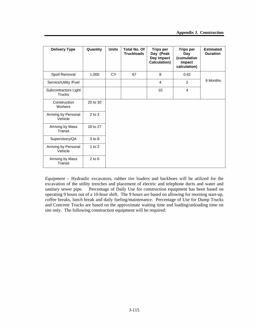
Appendix J. Construction
J-115
Equipment – Hydraulic excavators, rubber tire loaders and backhoes will be utilized for the excavation of the utility trenches and placement of electric and telephone ducts and water and sanitary sewer pipe. Percentage of Daily Use for construction equipment has been based on operating 9 hours out of a 10-hour shift. The 9 hours are based on allowing for morning start-up, coffee breaks, lunch break and daily fueling/maintenance. Percentage of Use for Dump Trucks and Concrete Trucks are based on the approximate waiting time and loading/unloading time on site only. The following construction equipment will be required:
Delivery Type Quantity Units Total No. Of Truckloads
Trips per Day (Peak Day impact Calculation)
Trips per Day
(cumulative impact
calculation)
Estimated Duration
Spoil Removal 1,000 CY 67 8 0.62
Service/Utility /Fuel 4 2
Subcontractors Light Trucks
10 4
9 Months
Construction Workers
20 to 30
Arriving by Personal Vehicle
2 to 3
Arriving by Mass Transit
18 to 27
Supervisory/QA 3 to 8
Arriving by Personal Vehicle
1 to 2
Arriving by Mass Transit
2 to 6
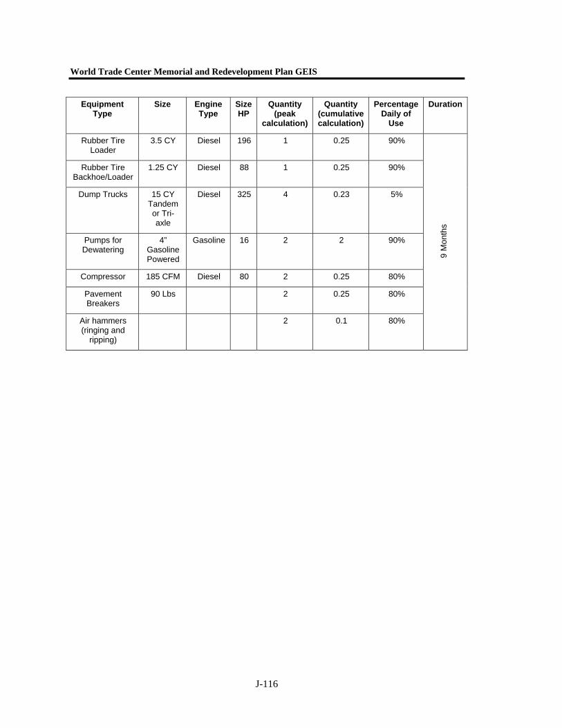
World Trade Center Memorial and Redevelopment Plan GEIS
J-116
Equipment Type
Size Engine Type
Size HP
Quantity (peak
calculation)
Quantity (cumulative calculation)
Percentage Daily of
Use
Duration
Rubber Tire Loader
3.5 CY Diesel 196 1 0.25 90%
Rubber Tire Backhoe/Loader
1.25 CY Diesel 88 1 0.25 90%
Dump Trucks 15 CY Tandem or Tri-axle
Diesel 325 4 0.23 5%
Pumps for Dewatering
4” Gasoline Powered
Gasoline 16 2 2 90%
Compressor 185 CFM Diesel 80 2 0.25 80%
Pavement Breakers
90 Lbs 2 0.25 80%
Air hammers (ringing and
ripping)
2 0.1 80%
9 M
onth
s

Appendix J. Construction
J-117
Slurry Wall
Delivery Type Per Segment
Quantity Units Total No. Of Truckloads
Trips per Day (Peak Day impact Calculation)
Trips per Day
(cumulative impact
calculation)
Estimated Duration
Slurry Wall – Exc. 2000 CY 35 6 1.9
Slurry Wall – Conc. 2000 CY 50 6 2.8
Slurry Wall - Rebar 120 Tons 2 2 0.1
Service/Utility /Fuel 6 4
Subcontractors Light Trucks
12 10
6 Month
Construction Workers
40 to 50
Arriving by Personal Vehicle
8 to 10
Arriving by Mass Transit
32 to 40
Supervisory/QA 4 to 6
Arriving by Personal Vehicle
1 to 2
Arriving by Mass Transit
3 to 4
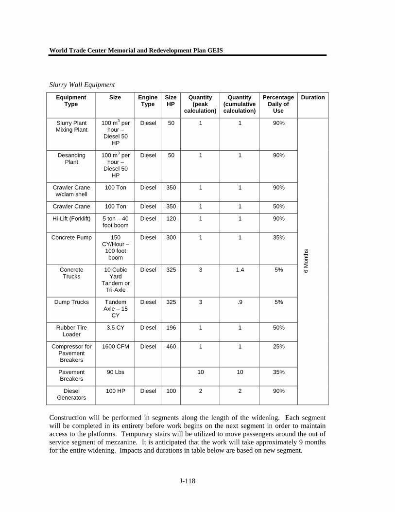
World Trade Center Memorial and Redevelopment Plan GEIS
J-118
Slurry Wall Equipment
Construction will be performed in segments along the length of the widening. Each segment will be completed in its entirety before work begins on the next segment in order to maintain access to the platforms. Temporary stairs will be utilized to move passengers around the out of service segment of mezzanine. It is anticipated that the work will take approximately 9 months for the entire widening. Impacts and durations in table below are based on new segment.
Equipment Type
Size Engine Type
Size HP
Quantity (peak
calculation)
Quantity (cumulative calculation)
Percentage Daily of
Use
Duration
Slurry Plant Mixing Plant
100 m3 per hour –
Diesel 50 HP
Diesel 50 1 1 90%
Desanding Plant
100 m3 per hour –
Diesel 50 HP
Diesel 50 1 1 90%
Crawler Crane w/clam shell
100 Ton Diesel 350 1 1 90%
Crawler Crane 100 Ton Diesel 350 1 1 50%
Hi-Lift (Forklift) 5 ton – 40 foot boom
Diesel 120 1 1 90%
Concrete Pump 150 CY/Hour – 100 foot boom
Diesel 300 1 1 35%
Concrete Trucks
10 Cubic Yard
Tandem or Tri-Axle
Diesel 325 3 1.4 5%
Dump Trucks Tandem Axle – 15
CY
Diesel 325 3 .9 5%
Rubber Tire Loader
3.5 CY Diesel 196 1 1 50%
Compressor for Pavement Breakers
1600 CFM Diesel 460 1 1 25%
Pavement Breakers
90 Lbs 10 10 35%
Diesel Generators
100 HP Diesel 100 2 2 90%
6 M
onth
s
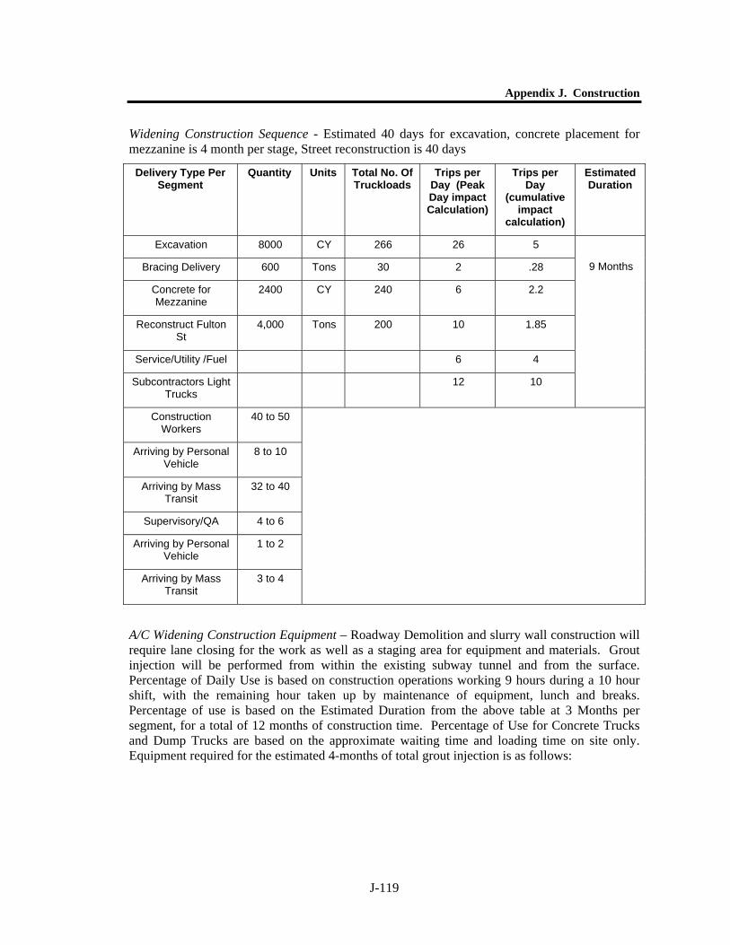
Appendix J. Construction
J-119
Widening Construction Sequence - Estimated 40 days for excavation, concrete placement for mezzanine is 4 month per stage, Street reconstruction is 40 days
A/C Widening Construction Equipment – Roadway Demolition and slurry wall construction will require lane closing for the work as well as a staging area for equipment and materials. Grout injection will be performed from within the existing subway tunnel and from the surface. Percentage of Daily Use is based on construction operations working 9 hours during a 10 hour shift, with the remaining hour taken up by maintenance of equipment, lunch and breaks. Percentage of use is based on the Estimated Duration from the above table at 3 Months per segment, for a total of 12 months of construction time. Percentage of Use for Concrete Trucks and Dump Trucks are based on the approximate waiting time and loading time on site only. Equipment required for the estimated 4-months of total grout injection is as follows:
Delivery Type Per Segment
Quantity Units Total No. Of Truckloads
Trips per Day (Peak Day impact Calculation)
Trips per Day
(cumulative impact
calculation)
Estimated Duration
Excavation 8000 CY 266 26 5
Bracing Delivery 600 Tons 30 2 .28
Concrete for Mezzanine
2400 CY 240 6 2.2
Reconstruct Fulton St
4,000 Tons 200 10 1.85
Service/Utility /Fuel 6 4
Subcontractors Light Trucks
12 10
9 Months
Construction Workers
40 to 50
Arriving by Personal Vehicle
8 to 10
Arriving by Mass Transit
32 to 40
Supervisory/QA 4 to 6
Arriving by Personal Vehicle
1 to 2
Arriving by Mass Transit
3 to 4
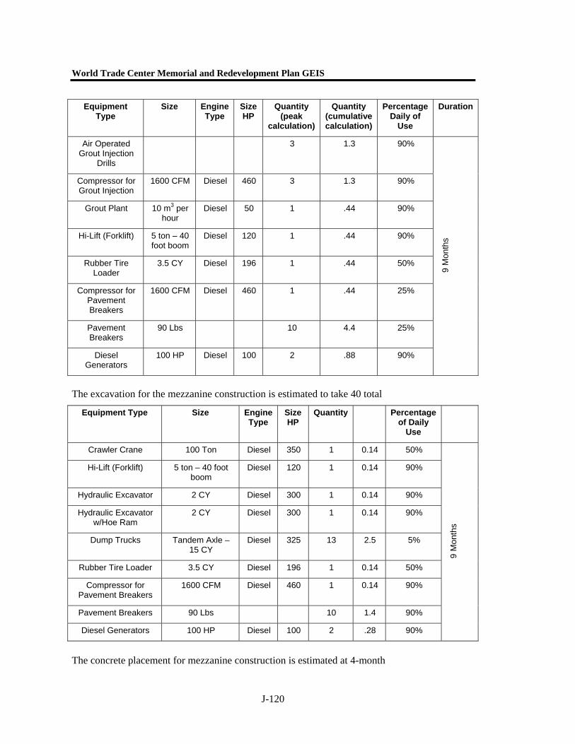
World Trade Center Memorial and Redevelopment Plan GEIS
J-120
The excavation for the mezzanine construction is estimated to take 40 total
The concrete placement for mezzanine construction is estimated at 4-month
Equipment Type
Size Engine Type
Size HP
Quantity (peak
calculation)
Quantity (cumulative calculation)
Percentage Daily of
Use
Duration
Air Operated Grout Injection
Drills
3 1.3 90%
Compressor for Grout Injection
1600 CFM Diesel 460 3 1.3 90%
Grout Plant 10 m3 per hour
Diesel 50 1 .44 90%
Hi-Lift (Forklift) 5 ton – 40 foot boom
Diesel 120 1 .44 90%
Rubber Tire Loader
3.5 CY Diesel 196 1 .44 50%
Compressor for Pavement Breakers
1600 CFM Diesel 460 1 .44 25%
Pavement Breakers
90 Lbs 10 4.4 25%
Diesel Generators
100 HP Diesel 100 2 .88 90%
9 M
onth
s
Equipment Type Size Engine Type
Size HP
Quantity Percentage of Daily
Use
Crawler Crane 100 Ton Diesel 350 1 0.14 50%
Hi-Lift (Forklift) 5 ton – 40 foot boom
Diesel 120 1 0.14 90%
Hydraulic Excavator 2 CY Diesel 300 1 0.14 90%
Hydraulic Excavator w/Hoe Ram
2 CY Diesel 300 1 0.14 90%
Dump Trucks Tandem Axle – 15 CY
Diesel 325 13 2.5 5%
Rubber Tire Loader 3.5 CY Diesel 196 1 0.14 50%
Compressor for Pavement Breakers
1600 CFM Diesel 460 1 0.14 90%
Pavement Breakers 90 Lbs 10 1.4 90%
Diesel Generators 100 HP Diesel 100 2 .28 90%
9 M
onth
s
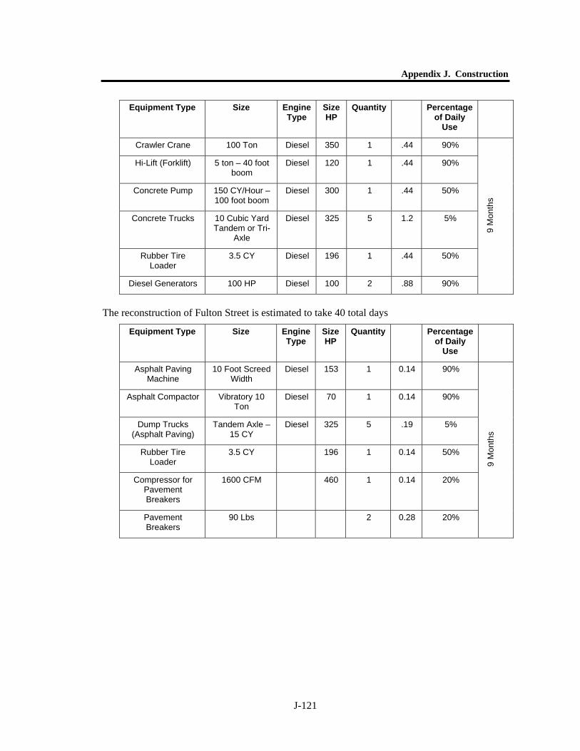
Appendix J. Construction
J-121
Equipment Type Size Engine Type
Size HP
Quantity Percentage of Daily
Use
Crawler Crane 100 Ton Diesel 350 1 .44 90%
Hi-Lift (Forklift) 5 ton – 40 foot boom
Diesel 120 1 .44 90%
Concrete Pump 150 CY/Hour – 100 foot boom
Diesel 300 1 .44 50%
Concrete Trucks 10 Cubic Yard Tandem or Tri-
Axle
Diesel 325 5 1.2 5%
Rubber Tire Loader
3.5 CY Diesel 196 1 .44 50%
Diesel Generators 100 HP Diesel 100 2 .88 90%
9 M
onth
s
The reconstruction of Fulton Street is estimated to take 40 total days
Equipment Type Size Engine Type
Size HP
Quantity Percentage of Daily
Use
Asphalt Paving Machine
10 Foot Screed Width
Diesel 153 1 0.14 90%
Asphalt Compactor Vibratory 10 Ton
Diesel 70 1 0.14 90%
Dump Trucks (Asphalt Paving)
Tandem Axle – 15 CY
Diesel 325 5 .19 5%
Rubber Tire Loader
3.5 CY 196 1 0.14 50%
Compressor for Pavement Breakers
1600 CFM 460 1 0.14 20%
Pavement Breakers
90 Lbs 2 0.28 20%
9 M
onth
s
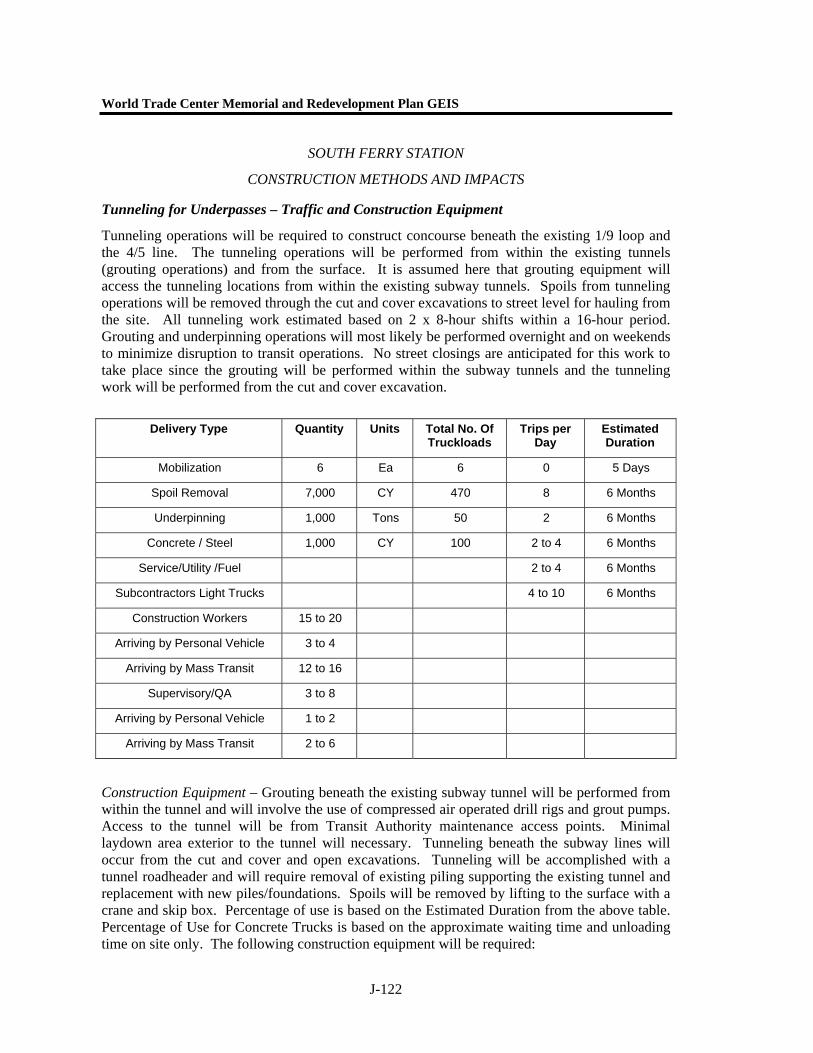
World Trade Center Memorial and Redevelopment Plan GEIS
J-122
SOUTH FERRY STATION
CONSTRUCTION METHODS AND IMPACTS
Tunneling for Underpasses – Traffic and Construction Equipment
Tunneling operations will be required to construct concourse beneath the existing 1/9 loop and the 4/5 line. The tunneling operations will be performed from within the existing tunnels (grouting operations) and from the surface. It is assumed here that grouting equipment will access the tunneling locations from within the existing subway tunnels. Spoils from tunneling operations will be removed through the cut and cover excavations to street level for hauling from the site. All tunneling work estimated based on 2 x 8-hour shifts within a 16-hour period. Grouting and underpinning operations will most likely be performed overnight and on weekends to minimize disruption to transit operations. No street closings are anticipated for this work to take place since the grouting will be performed within the subway tunnels and the tunneling work will be performed from the cut and cover excavation.
Construction Equipment – Grouting beneath the existing subway tunnel will be performed from within the tunnel and will involve the use of compressed air operated drill rigs and grout pumps. Access to the tunnel will be from Transit Authority maintenance access points. Minimal laydown area exterior to the tunnel will necessary. Tunneling beneath the subway lines will occur from the cut and cover and open excavations. Tunneling will be accomplished with a tunnel roadheader and will require removal of existing piling supporting the existing tunnel and replacement with new piles/foundations. Spoils will be removed by lifting to the surface with a crane and skip box. Percentage of use is based on the Estimated Duration from the above table. Percentage of Use for Concrete Trucks is based on the approximate waiting time and unloading time on site only. The following construction equipment will be required:
Delivery Type Quantity Units Total No. Of Truckloads
Trips per Day
Estimated Duration
Mobilization 6 Ea 6 0 5 Days
Spoil Removal 7,000 CY 470 8 6 Months
Underpinning 1,000 Tons 50 2 6 Months
Concrete / Steel 1,000 CY 100 2 to 4 6 Months
Service/Utility /Fuel 2 to 4 6 Months
Subcontractors Light Trucks 4 to 10 6 Months
Construction Workers 15 to 20
Arriving by Personal Vehicle 3 to 4
Arriving by Mass Transit 12 to 16
Supervisory/QA 3 to 8
Arriving by Personal Vehicle 1 to 2
Arriving by Mass Transit 2 to 6
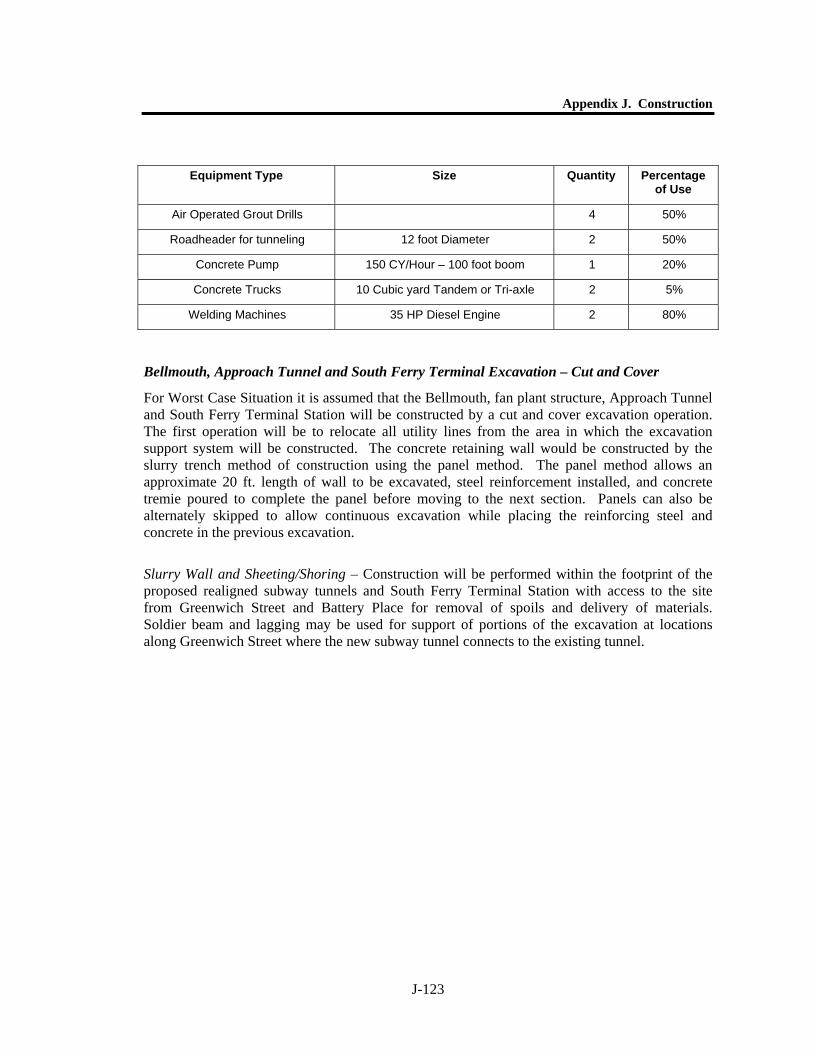
Appendix J. Construction
J-123
Bellmouth, Approach Tunnel and South Ferry Terminal Excavation – Cut and Cover
For Worst Case Situation it is assumed that the Bellmouth, fan plant structure, Approach Tunnel and South Ferry Terminal Station will be constructed by a cut and cover excavation operation. The first operation will be to relocate all utility lines from the area in which the excavation support system will be constructed. The concrete retaining wall would be constructed by the slurry trench method of construction using the panel method. The panel method allows an approximate 20 ft. length of wall to be excavated, steel reinforcement installed, and concrete tremie poured to complete the panel before moving to the next section. Panels can also be alternately skipped to allow continuous excavation while placing the reinforcing steel and concrete in the previous excavation.
Slurry Wall and Sheeting/Shoring – Construction will be performed within the footprint of the proposed realigned subway tunnels and South Ferry Terminal Station with access to the site from Greenwich Street and Battery Place for removal of spoils and delivery of materials. Soldier beam and lagging may be used for support of portions of the excavation at locations along Greenwich Street where the new subway tunnel connects to the existing tunnel.
Equipment Type Size Quantity Percentage of Use
Air Operated Grout Drills 4 50%
Roadheader for tunneling 12 foot Diameter 2 50%
Concrete Pump 150 CY/Hour – 100 foot boom 1 20%
Concrete Trucks 10 Cubic yard Tandem or Tri-axle 2 5%
Welding Machines 35 HP Diesel Engine 2 80%
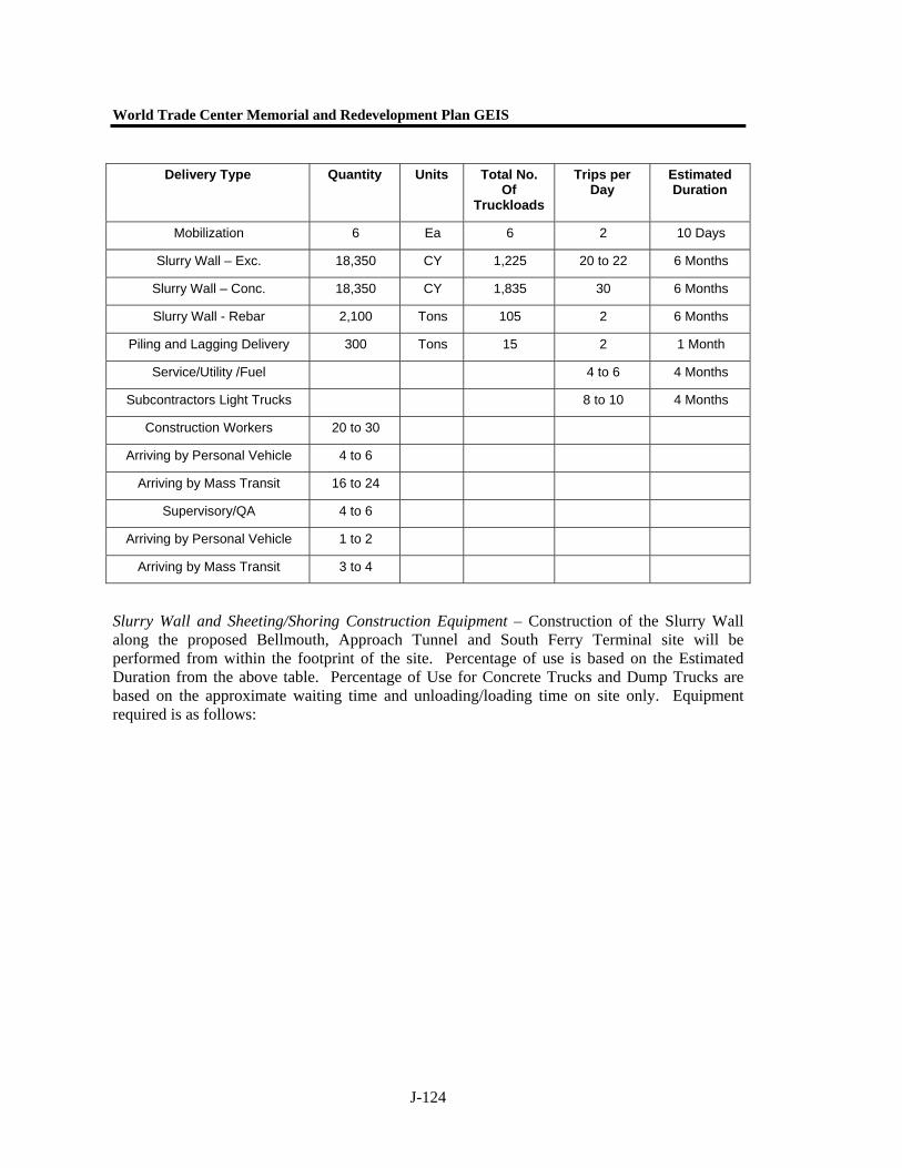
World Trade Center Memorial and Redevelopment Plan GEIS
J-124
Slurry Wall and Sheeting/Shoring Construction Equipment – Construction of the Slurry Wall along the proposed Bellmouth, Approach Tunnel and South Ferry Terminal site will be performed from within the footprint of the site. Percentage of use is based on the Estimated Duration from the above table. Percentage of Use for Concrete Trucks and Dump Trucks are based on the approximate waiting time and unloading/loading time on site only. Equipment required is as follows:
Delivery Type Quantity Units Total No. Of
Truckloads
Trips per Day
Estimated Duration
Mobilization 6 Ea 6 2 10 Days
Slurry Wall – Exc. 18,350 CY 1,225 20 to 22 6 Months
Slurry Wall – Conc. 18,350 CY 1,835 30 6 Months
Slurry Wall - Rebar 2,100 Tons 105 2 6 Months
Piling and Lagging Delivery 300 Tons 15 2 1 Month
Service/Utility /Fuel 4 to 6 4 Months
Subcontractors Light Trucks 8 to 10 4 Months
Construction Workers 20 to 30
Arriving by Personal Vehicle 4 to 6
Arriving by Mass Transit 16 to 24
Supervisory/QA 4 to 6
Arriving by Personal Vehicle 1 to 2
Arriving by Mass Transit 3 to 4
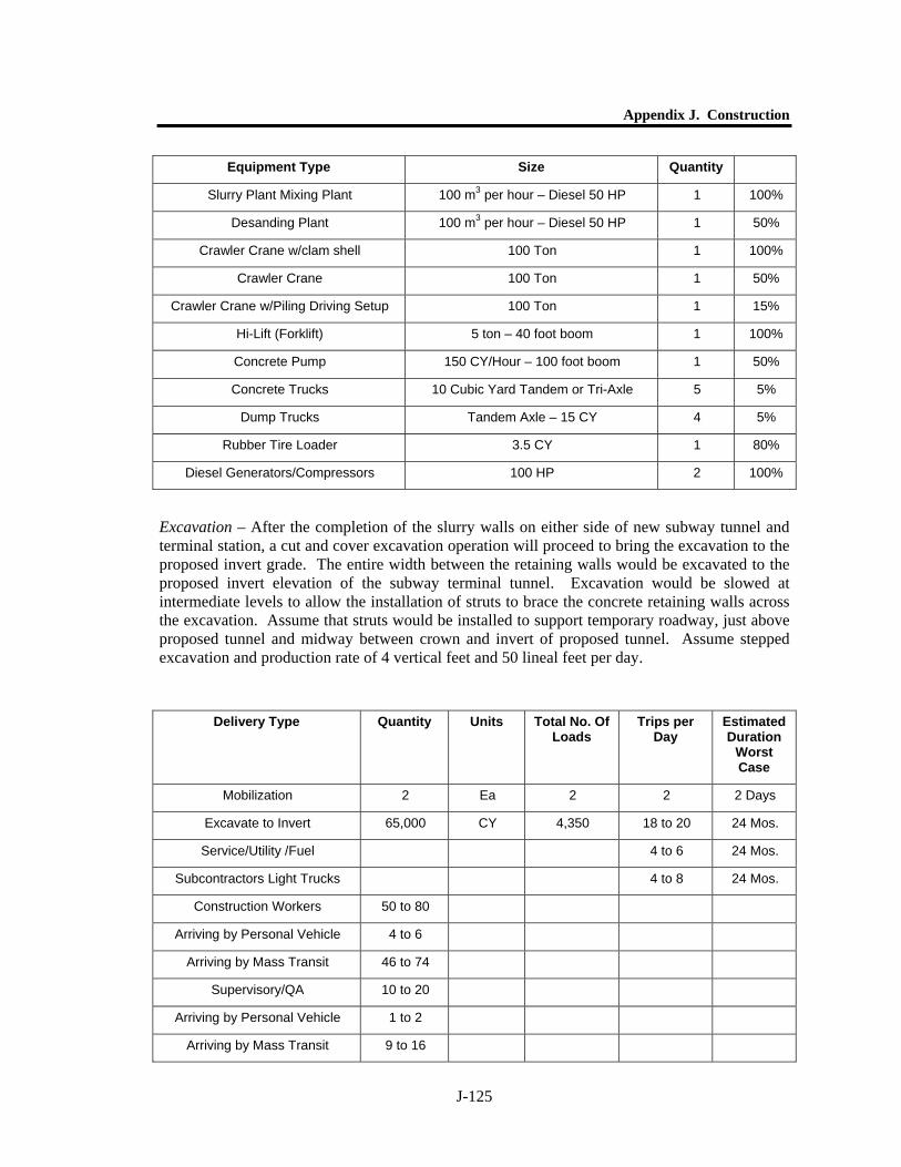
Appendix J. Construction
J-125
Excavation – After the completion of the slurry walls on either side of new subway tunnel and terminal station, a cut and cover excavation operation will proceed to bring the excavation to the proposed invert grade. The entire width between the retaining walls would be excavated to the proposed invert elevation of the subway terminal tunnel. Excavation would be slowed at intermediate levels to allow the installation of struts to brace the concrete retaining walls across the excavation. Assume that struts would be installed to support temporary roadway, just above proposed tunnel and midway between crown and invert of proposed tunnel. Assume stepped excavation and production rate of 4 vertical feet and 50 lineal feet per day.
Equipment Type Size Quantity
Slurry Plant Mixing Plant 100 m3 per hour – Diesel 50 HP 1 100%
Desanding Plant 100 m3 per hour – Diesel 50 HP 1 50%
Crawler Crane w/clam shell 100 Ton 1 100%
Crawler Crane 100 Ton 1 50%
Crawler Crane w/Piling Driving Setup 100 Ton 1 15%
Hi-Lift (Forklift) 5 ton – 40 foot boom 1 100%
Concrete Pump 150 CY/Hour – 100 foot boom 1 50%
Concrete Trucks 10 Cubic Yard Tandem or Tri-Axle 5 5%
Dump Trucks Tandem Axle – 15 CY 4 5%
Rubber Tire Loader 3.5 CY 1 80%
Diesel Generators/Compressors 100 HP 2 100%
Delivery Type
Quantity Units Total No. Of Loads
Trips per Day
Estimated Duration
Worst Case
Mobilization 2 Ea 2 2 2 Days
Excavate to Invert 65,000 CY 4,350 18 to 20 24 Mos.
Service/Utility /Fuel 4 to 6 24 Mos.
Subcontractors Light Trucks 4 to 8 24 Mos.
Construction Workers 50 to 80
Arriving by Personal Vehicle 4 to 6
Arriving by Mass Transit 46 to 74
Supervisory/QA 10 to 20
Arriving by Personal Vehicle 1 to 2
Arriving by Mass Transit 9 to 16
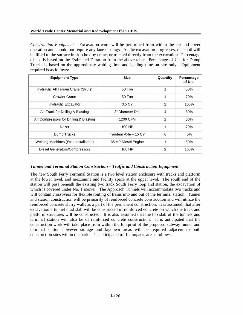
World Trade Center Memorial and Redevelopment Plan GEIS
J-126
Construction Equipment – Excavation work will be performed from within the cut and cover operation and should not require any lane closings. As the excavation progresses, the spoil will be lifted to the surface in skip box by crane, or trucked directly from the excavation. Percentage of use is based on the Estimated Duration from the above table. Percentage of Use for Dump Trucks is based on the approximate waiting time and loading time on site only. Equipment required is as follows:
Tunnel and Terminal Station Construction – Traffic and Construction Equipment
The new South Ferry Terminal Station is a two level station enclosure with tracks and platform at the lower level, and mezzanine and facility space at the upper level. The south end of the station will pass beneath the existing two track South Ferry loop and station, the excavation of which is covered under No. 1 above. The Approach Tunnels will accommodate two tracks and will contain crossovers for flexible routing of trains into and out of the terminal station. Tunnel and station construction will be primarily of reinforced concrete construction and will utilize the reinforced concrete slurry walls as a part of the permanent construction. It is assumed, that after excavation a tunnel mud slab will be constructed of reinforced concrete on which the track and platform structures will be constructed. It is also assumed that the top slab of the tunnels and terminal station will also be of reinforced concrete construction. It is anticipated that the construction work will take place from within the footprint of the proposed subway tunnel and terminal station however storage and laydown areas will be required adjacent to both construction sites within the park. The anticipated traffic impacts are as follows:
Equipment Type Size Quantity Percentage of Use
Hydraulic All Terrain Crane (Struts) 50 Ton 1 50%
Crawler Crane 50 Ton 1 70%
Hydraulic Excavator 3.5 CY 2 100%
Air Track for Drilling & Blasting 3” Diameter Drill 4 50%
Air Compressors for Drilling & Blasting 1200 CFM 2 50%
Dozer 100 HP 1 70%
Dump Trucks Tandem Axle – 15 CY 6 5%
Welding Machines (Strut Installation) 35 HP Diesel Engine 1 50%
Diesel Generators/Compressors 100 HP 2 100%
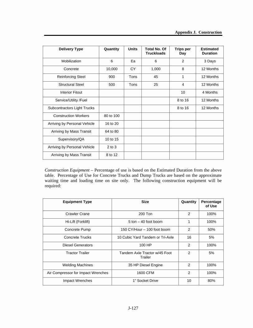
Appendix J. Construction
J-127
Construction Equipment – Percentage of use is based on the Estimated Duration from the above table. Percentage of Use for Concrete Trucks and Dump Trucks are based on the approximate waiting time and loading time on site only. The following construction equipment will be required:
Delivery Type Quantity Units Total No. Of Truckloads
Trips per Day
Estimated Duration
Mobilization 6 Ea 6 2 3 Days
Concrete 10,000 CY 1,000 8 12 Months
Reinforcing Steel 900 Tons 45 1 12 Months
Structural Steel 500 Tons 25 4 12 Months
Interior Fitout 10 4 Months
Service/Utility /Fuel 8 to 16 12 Months
Subcontractors Light Trucks 8 to 16 12 Months
Construction Workers 80 to 100
Arriving by Personal Vehicle 16 to 20
Arriving by Mass Transit 64 to 80
Supervisory/QA 10 to 15
Arriving by Personal Vehicle 2 to 3
Arriving by Mass Transit 8 to 12
Equipment Type Size Quantity Percentage of Use
Crawler Crane 200 Ton 2 100%
Hi-Lift (Forklift) 5 ton – 40 foot boom 1 100%
Concrete Pump 150 CY/Hour – 100 foot boom 2 50%
Concrete Trucks 10 Cubic Yard Tandem or Tri-Axle 16 5%
Diesel Generators 100 HP 2 100%
Tractor Trailer Tandem Axle Tractor w/45 Foot Trailer
2 5%
Welding Machines 35 HP Diesel Engine 2 100%
Air Compressor for Impact Wrenches 1600 CFM 2 100%
Impact Wrenches 1” Socket Drive 10 80%
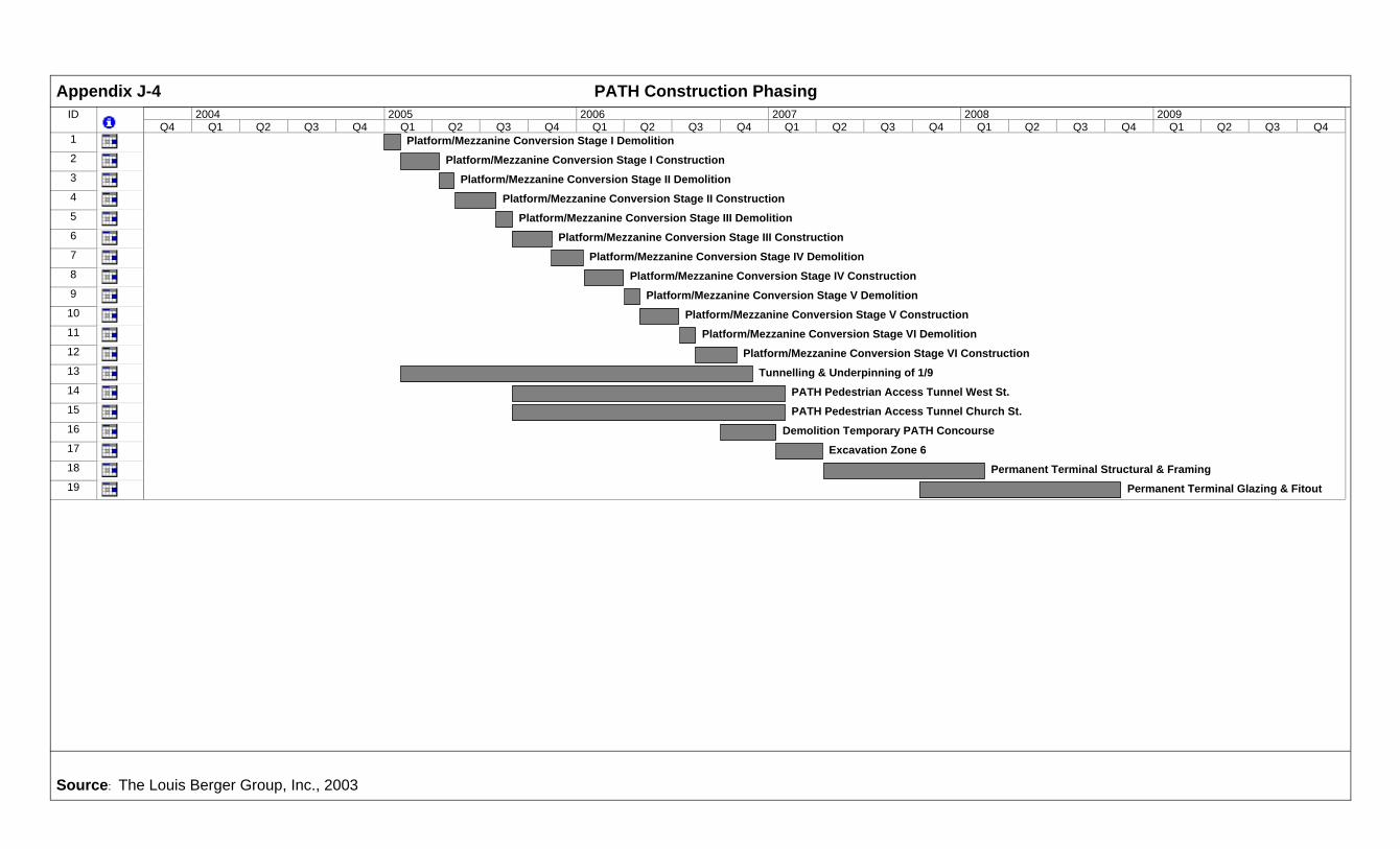
ID
1
2
3
4
5
6
7
8
9
10
11
12
13
14
15
16
17
18
19
Platform/Mezzanine Conversion Stage I Demolition
Platform/Mezzanine Conversion Stage I Construction
Platform/Mezzanine Conversion Stage II Demolition
Platform/Mezzanine Conversion Stage II Construction
Platform/Mezzanine Conversion Stage III Demolition
Platform/Mezzanine Conversion Stage III Construction
Platform/Mezzanine Conversion Stage IV Demolition
Platform/Mezzanine Conversion Stage IV Construction
Platform/Mezzanine Conversion Stage V Demolition
Platform/Mezzanine Conversion Stage V Construction
Platform/Mezzanine Conversion Stage VI Demolition
Platform/Mezzanine Conversion Stage VI Construction
Tunnelling & Underpinning of 1/9
PATH Pedestrian Access Tunnel West St.
PATH Pedestrian Access Tunnel Church St.
Demolition Temporary PATH Concourse
Excavation Zone 6
Permanent Terminal Structural & Framing
Permanent Terminal Glazing & Fitout
Q4 Q1 Q2 Q3 Q4 Q1 Q2 Q3 Q4 Q1 Q2 Q3 Q4 Q1 Q2 Q3 Q4 Q1 Q2 Q3 Q4 Q1 Q2 Q3 Q42004 2005 2006 2007 2008 2009
Appendix J-4 PATH Construction Phasing
Source: The Louis Berger Group, Inc., 2003

ID
1
2
3
4
5
6
7
8
9
10
11
12
13
14
15
Early Action Items - Utility Relocations
Stage I Fill Placement
Stage I Paving & Barriers
Stage II Slurry Wall
Stage II Excavation
Stage II Concrete Box
Stage II Road Deck
Stage II Backfill
Stage II Roadway
Stage III Excavation/Demolition
Stage III Concrete Box
Stage III Road Deck
Stage III Backfill
Stage III Roadway Surface
Stage IV Surface & Tunnel Finished
Q4 Q1 Q2 Q3 Q4 Q1 Q2 Q3 Q4 Q1 Q2 Q3 Q4 Q1 Q2 Q3 Q4 Q1 Q2 Q3 Q4 Q1 Q2 Q32004 2005 2006 2007 2008 2009
Appendix J-5 Route 9A Construction Phasing Schedule
Source: The Louis Berger Group, Inc., 2003
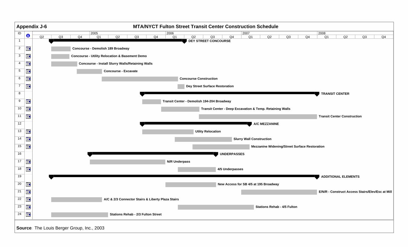
ID
1
2
3
4
5
6
7
8
9
10
11
12
13
14
15
16
17
18
19
20
21
22
23
24
DEY STREET CONCOURSE
Concourse - Demolish 189 Broadway
Concourse - Utility Relocation & Basement Demo
Concourse - Install Slurry Walls/Retaining Walls
Concourse - Excavate
Concourse Construction
Dey Street Surface Restoration
TRANSIT CENTER
Transit Center - Demolish 194-204 Broadway
Transit Center - Deep Excavation & Temp. Retaining Walls
Transit Center Construction
A/C MEZZANINE
Utlity Relocation
Slurry Wall Construction
Mezzanine Widening/Street Surface Restoration
UNDERPASSES
N/R Underpass
4/5 Underpasses
ADDITIONAL ELEMENTS
New Access for SB 4/5 at 195 Broadway
E/N/R - Construct Access Stairs/Elev/Esc at Mill
A/C & 2/3 Connector Stairs & Liberty Plaza Stairs
Stations Rehab - 4/5 Fulton
Stations Rehab - 2/3 Fulton Street
Q2 Q3 Q4 Q1 Q2 Q3 Q4 Q1 Q2 Q3 Q4 Q1 Q2 Q3 Q4 Q1 Q2 Q3 Q42005 2006 2007 2008
Appendix J-6 MTA/NYCT Fulton Street Transit Center Construction Schedule
Source: The Louis Berger Group, Inc., 2003
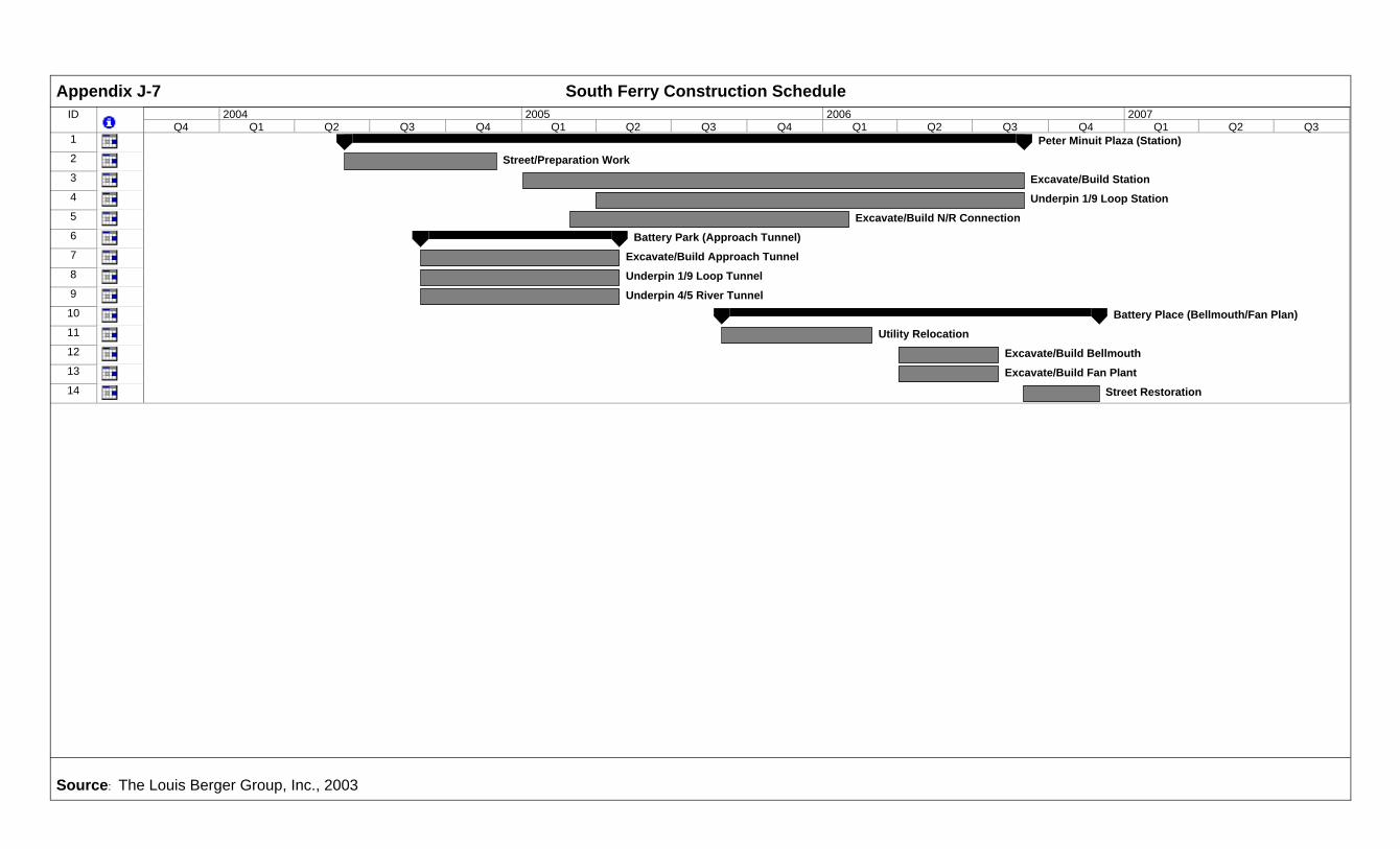
ID
1
2
3
4
5
6
7
8
9
10
11
12
13
14
Peter Minuit Plaza (Station)
Street/Preparation Work
Excavate/Build Station
Underpin 1/9 Loop Station
Excavate/Build N/R Connection
Battery Park (Approach Tunnel)
Excavate/Build Approach Tunnel
Underpin 1/9 Loop Tunnel
Underpin 4/5 River Tunnel
Battery Place (Bellmouth/Fan Plan)
Utility Relocation
Excavate/Build Bellmouth
Excavate/Build Fan Plant
Street Restoration
Q4 Q1 Q2 Q3 Q4 Q1 Q2 Q3 Q4 Q1 Q2 Q3 Q4 Q1 Q2 Q32004 2005 2006 2007
Appendix J-7 South Ferry Construction Schedule
Source: The Louis Berger Group, Inc., 2003
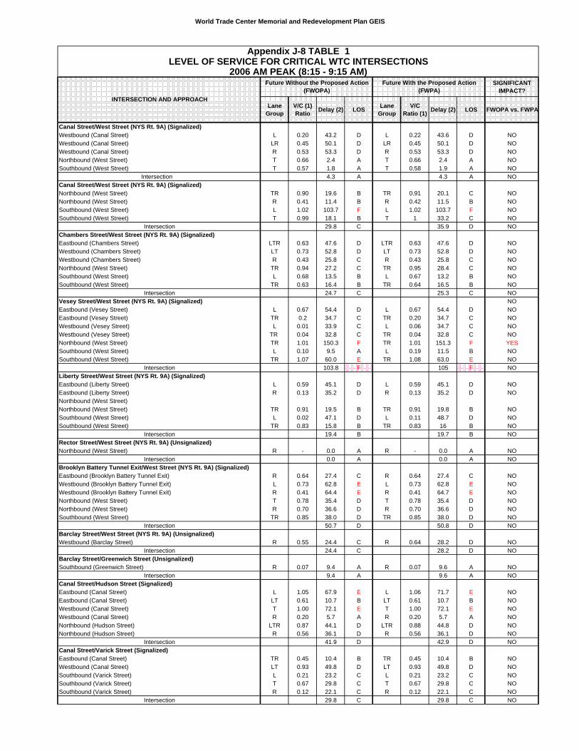
World Trade Center Memorial and Redevelopment Plan GEIS
SIGNIFICANT IMPACT?
Lane Group
V/C (1) Ratio Delay (2) LOS Lane
GroupV/C
Ratio (1) Delay (2) LOS FWOPA vs. FWPA
Canal Street/West Street (NYS Rt. 9A) (Signalized)Westbound (Canal Street) L 0.20 43.2 D L 0.22 43.6 D NOWestbound (Canal Street) LR 0.45 50.1 D LR 0.45 50.1 D NOWestbound (Canal Street) R 0.53 53.3 D R 0.53 53.3 D NONorthbound (West Street) T 0.66 2.4 A T 0.66 2.4 A NOSouthbound (West Street) T 0.57 1.8 A T 0.58 1.9 A NO
Intersection 4.3 A 4.3 A NOCanal Street/West Street (NYS Rt. 9A) (Signalized)Northbound (West Street) TR 0.90 19.6 B TR 0.91 20.1 C NONorthbound (West Street) R 0.41 11.4 B R 0.42 11.5 B NOSouthbound (West Street) L 1.02 103.7 F L 1.02 103.7 F NOSouthbound (West Street) T 0.99 18.1 B T 1 33.2 C NO
Intersection 29.8 C 35.9 D NOChambers Street/West Street (NYS Rt. 9A) (Signalized)Eastbound (Chambers Street) LTR 0.63 47.6 D LTR 0.63 47.6 D NOWestbound (Chambers Street) LT 0.73 52.8 D LT 0.73 52.8 D NOWestbound (Chambers Street) R 0.43 25.8 C R 0.43 25.8 C NONorthbound (West Street) TR 0.94 27.2 C TR 0.95 28.4 C NOSouthbound (West Street) L 0.68 13.5 B L 0.67 13.2 B NOSouthbound (West Street) TR 0.63 16.4 B TR 0.64 16.5 B NO
Intersection 24.7 C 25.3 C NOVesey Street/West Street (NYS Rt. 9A) (Signalized) NOEastbound (Vesey Street) L 0.67 54.4 D L 0.67 54.4 D NOEastbound (Vesey Street) TR 0.2 34.7 C TR 0.20 34.7 C NOWestbound (Vesey Street) L 0.01 33.9 C L 0.06 34.7 C NOWestbound (Vesey Street) TR 0.04 32.8 C TR 0.04 32.8 C NONorthbound (West Street) TR 1.01 150.3 F TR 1.01 151.3 F YESSouthbound (West Street) L 0.10 9.5 A L 0.19 11.5 B NOSouthbound (West Street) TR 1.07 60.0 E TR 1.08 63.0 E NO
Intersection 103.8 F 105 F NOLiberty Street/West Street (NYS Rt. 9A) (Signalized)Eastbound (Liberty Street) L 0.59 45.1 D L 0.59 45.1 D NOEastbound (Liberty Street) R 0.13 35.2 D R 0.13 35.2 D NONorthbound (West Street)Northbound (West Street) TR 0.91 19.5 B TR 0.91 19.8 B NOSouthbound (West Street) L 0.02 47.1 D L 0.11 48.7 D NOSouthbound (West Street) TR 0.83 15.8 B TR 0.83 16 B NO
Intersection 19.4 B 19.7 B NORector Street/West Street (NYS Rt. 9A) (Unsignalized)Northbound (West Street) R - 0.0 A R - 0.0 A NO
Intersection 0.0 A 0.0 A NOBrooklyn Battery Tunnel Exit/West Street (NYS Rt. 9A) (Signalized)Eastbound (Brooklyn Battery Tunnel Exit) R 0.64 27.4 C R 0.64 27.4 C NOWestbound (Brooklyn Battery Tunnel Exit) L 0.73 62.8 E L 0.73 62.8 E NOWestbound (Brooklyn Battery Tunnel Exit) R 0.41 64.4 E R 0.41 64.7 E NONorthbound (West Street) T 0.78 35.4 D T 0.78 35.4 D NONorthbound (West Street) R 0.70 36.6 D R 0.70 36.6 D NOSouthbound (West Street) TR 0.85 38.0 D TR 0.85 38.0 D NO
Intersection 50.7 D 50.8 D NOBarclay Street/West Street (NYS Rt. 9A) (Unsignalized)Westbound (Barclay Street) R 0.55 24.4 C R 0.64 28.2 D NO
Intersection 24.4 C 28.2 D NOBarclay Street/Greenwich Street (Unsignalized)Southbound (Greenwich Street) R 0.07 9.4 A R 0.07 9.6 A NO
Intersection 9.4 A 9.6 A NOCanal Street/Hudson Street (Signalized)Eastbound (Canal Street) L 1.05 67.9 E L 1.06 71.7 E NOEastbound (Canal Street) LT 0.61 10.7 B LT 0.61 10.7 B NOWestbound (Canal Street) T 1.00 72.1 E T 1.00 72.1 E NOWestbound (Canal Street) R 0.20 5.7 A R 0.20 5.7 A NONorthbound (Hudson Street) LTR 0.87 44.1 D LTR 0.88 44.8 D NONorthbound (Hudson Street) R 0.56 36.1 D R 0.56 36.1 D NO
Intersection 41.9 D 42.9 D NOCanal Street/Varick Street (Signalized)Eastbound (Canal Street) TR 0.45 10.4 B TR 0.45 10.4 B NOWestbound (Canal Street) LT 0.93 49.8 D LT 0.93 49.8 D NOSouthbound (Varick Street) L 0.21 23.2 C L 0.21 23.2 C NOSouthbound (Varick Street) T 0.67 29.8 C T 0.67 29.8 C NOSouthbound (Varick Street) R 0.12 22.1 C R 0.12 22.1 C NO
Intersection 29.8 C 29.8 C NO
INTERSECTION AND APPROACH
Appendix J-8 TABLE 1LEVEL OF SERVICE FOR CRITICAL WTC INTERSECTIONS
2006 AM PEAK (8:15 - 9:15 AM)Future With the Proposed Action
(FWPA)Future Without the Proposed Action
(FWOPA)
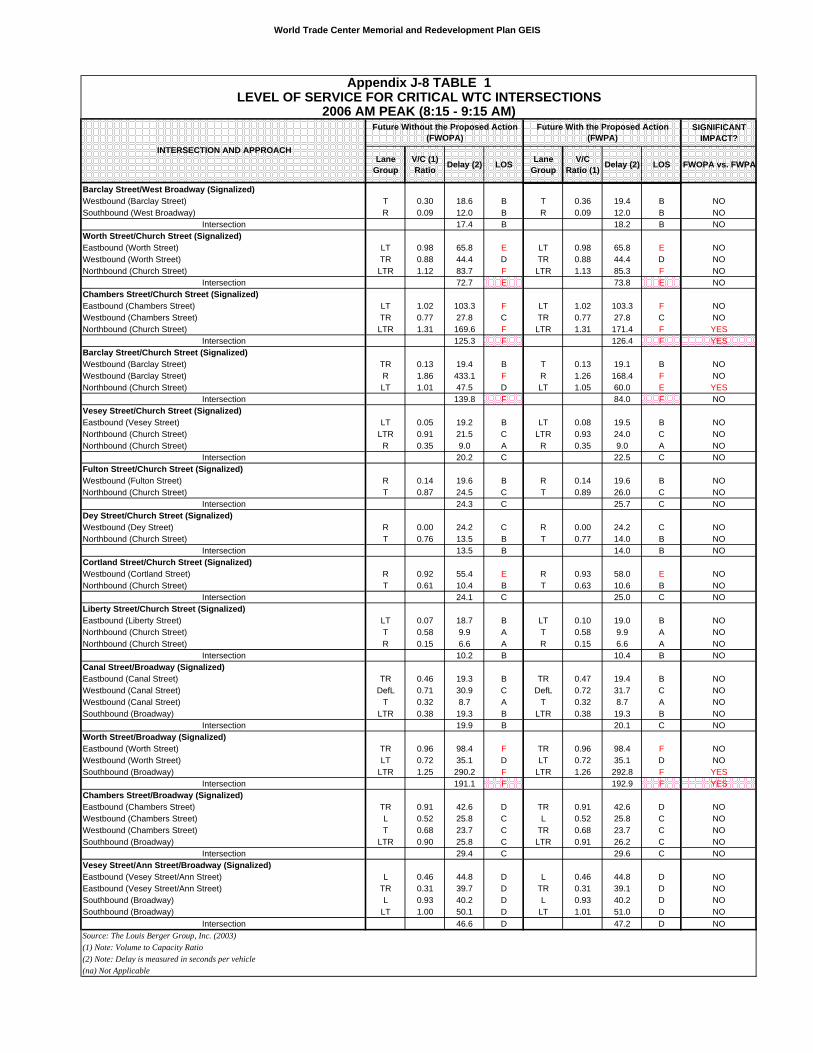
World Trade Center Memorial and Redevelopment Plan GEIS
SIGNIFICANT IMPACT?
Lane Group
V/C (1) Ratio Delay (2) LOS Lane
GroupV/C
Ratio (1) Delay (2) LOS FWOPA vs. FWPAINTERSECTION AND APPROACH
Appendix J-8 TABLE 1LEVEL OF SERVICE FOR CRITICAL WTC INTERSECTIONS
2006 AM PEAK (8:15 - 9:15 AM)Future With the Proposed Action
(FWPA)Future Without the Proposed Action
(FWOPA)
Barclay Street/West Broadway (Signalized)Westbound (Barclay Street) T 0.30 18.6 B T 0.36 19.4 B NOSouthbound (West Broadway) R 0.09 12.0 B R 0.09 12.0 B NO
Intersection 17.4 B 18.2 B NOWorth Street/Church Street (Signalized)Eastbound (Worth Street) LT 0.98 65.8 E LT 0.98 65.8 E NOWestbound (Worth Street) TR 0.88 44.4 D TR 0.88 44.4 D NONorthbound (Church Street) LTR 1.12 83.7 F LTR 1.13 85.3 F NO
Intersection 72.7 E 73.8 E NOChambers Street/Church Street (Signalized)Eastbound (Chambers Street) LT 1.02 103.3 F LT 1.02 103.3 F NOWestbound (Chambers Street) TR 0.77 27.8 C TR 0.77 27.8 C NONorthbound (Church Street) LTR 1.31 169.6 F LTR 1.31 171.4 F YES
Intersection 125.3 F 126.4 F YESBarclay Street/Church Street (Signalized)Westbound (Barclay Street) TR 0.13 19.4 B T 0.13 19.1 B NOWestbound (Barclay Street) R 1.86 433.1 F R 1.26 168.4 F NONorthbound (Church Street) LT 1.01 47.5 D LT 1.05 60.0 E YES
Intersection 139.8 F 84.0 F NOVesey Street/Church Street (Signalized)Eastbound (Vesey Street) LT 0.05 19.2 B LT 0.08 19.5 B NONorthbound (Church Street) LTR 0.91 21.5 C LTR 0.93 24.0 C NONorthbound (Church Street) R 0.35 9.0 A R 0.35 9.0 A NO
Intersection 20.2 C 22.5 C NOFulton Street/Church Street (Signalized)Westbound (Fulton Street) R 0.14 19.6 B R 0.14 19.6 B NONorthbound (Church Street) T 0.87 24.5 C T 0.89 26.0 C NO
Intersection 24.3 C 25.7 C NODey Street/Church Street (Signalized)Westbound (Dey Street) R 0.00 24.2 C R 0.00 24.2 C NONorthbound (Church Street) T 0.76 13.5 B T 0.77 14.0 B NO
Intersection 13.5 B 14.0 B NOCortland Street/Church Street (Signalized)Westbound (Cortland Street) R 0.92 55.4 E R 0.93 58.0 E NONorthbound (Church Street) T 0.61 10.4 B T 0.63 10.6 B NO
Intersection 24.1 C 25.0 C NOLiberty Street/Church Street (Signalized)Eastbound (Liberty Street) LT 0.07 18.7 B LT 0.10 19.0 B NONorthbound (Church Street) T 0.58 9.9 A T 0.58 9.9 A NONorthbound (Church Street) R 0.15 6.6 A R 0.15 6.6 A NO
Intersection 10.2 B 10.4 B NOCanal Street/Broadway (Signalized)Eastbound (Canal Street) TR 0.46 19.3 B TR 0.47 19.4 B NOWestbound (Canal Street) DefL 0.71 30.9 C DefL 0.72 31.7 C NOWestbound (Canal Street) T 0.32 8.7 A T 0.32 8.7 A NOSouthbound (Broadway) LTR 0.38 19.3 B LTR 0.38 19.3 B NO
Intersection 19.9 B 20.1 C NOWorth Street/Broadway (Signalized)Eastbound (Worth Street) TR 0.96 98.4 F TR 0.96 98.4 F NOWestbound (Worth Street) LT 0.72 35.1 D LT 0.72 35.1 D NOSouthbound (Broadway) LTR 1.25 290.2 F LTR 1.26 292.8 F YES
Intersection 191.1 F 192.9 F YESChambers Street/Broadway (Signalized)Eastbound (Chambers Street) TR 0.91 42.6 D TR 0.91 42.6 D NOWestbound (Chambers Street) L 0.52 25.8 C L 0.52 25.8 C NOWestbound (Chambers Street) T 0.68 23.7 C TR 0.68 23.7 C NOSouthbound (Broadway) LTR 0.90 25.8 C LTR 0.91 26.2 C NO
Intersection 29.4 C 29.6 C NOVesey Street/Ann Street/Broadway (Signalized)Eastbound (Vesey Street/Ann Street) L 0.46 44.8 D L 0.46 44.8 D NOEastbound (Vesey Street/Ann Street) TR 0.31 39.7 D TR 0.31 39.1 D NOSouthbound (Broadway) L 0.93 40.2 D L 0.93 40.2 D NOSouthbound (Broadway) LT 1.00 50.1 D LT 1.01 51.0 D NO
Intersection 46.6 D 47.2 D NOSource: The Louis Berger Group, Inc. (2003)(1) Note: Volume to Capacity Ratio(2) Note: Delay is measured in seconds per vehicle(na) Not Applicable
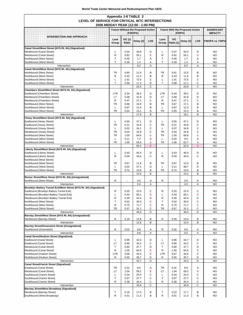
World Trade Center Memorial and Redevelopment Plan GEIS
SIGNIFICANT IMPACT?
Lane Group
V/C (1) Ratio Delay (2) LOS Lane
GroupV/C
Ratio (1) Delay (2) LOS FWOPA vs. FWPA
Canal Street/West Street (NYS Rt. 9A) (Signalized)Westbound (Canal Street) L 0.34 43.8 D L 0.37 44.3 D NOWestbound (Canal Street) R 0.62 55.1 E R 0.62 55.1 E NONorthbound (West Street) T 0.45 1.7 A T 0.46 1.7 A NOSouthbound (West Street) T 0.39 1.4 A T 0.39 1.4 A NO
Intersection 8.2 A 8.2 A NOCanal Street/West Street (NYS Rt. 9A) (Signalized)Northbound (West Street) TR 0.60 11.9 B TR 0.61 12.0 B NONorthbound (West Street) R 0.42 11.4 B R 0.43 11.6 B NOSouthbound (West Street) L 1.01 72.5 E L 1.01 72.5 E NOSouthbound (West Street) T 0.96 17.3 B T 0.98 21.1 C NO
Intersection 22.5 C 23.9 C NOChambers Street/West Street (NYS Rt. 9A) (Signalized)Eastbound (Chambers Street) LTR 0.34 39.2 D LTR 0.34 39.2 D NOWestbound (Chambers Street) LT 0.48 41.8 D LT 0.48 41.8 D NOWestbound (Chambers Street) R 0.47 27.1 C R 0.47 27.1 C NONorthbound (West Street) TR 0.66 16.9 B TR 0.67 17.1 B NOSouthbound (West Street) L 0.67 11.9 B L 0.67 12.3 B NOSouthbound (West Street) TR 0.54 15.1 B TR 0.55 15.3 B NO
Intersection 17.9 B 18.1 B NOVesey Street/West Street (NYS Rt. 9A) (Signalized)Eastbound (Vesey Street) L 0.55 47.1 D L 0.55 47.1 D NOEastbound (Vesey Street) TR 0.21 34.8 C TR 0.21 34.8 C NOWestbound (Vesey Street) L 0.02 34.1 C L 0.07 34.9 C NOWestbound (Vesey Street) TR 0.04 32.8 C TR 0.04 32.8 C NONorthbound (West Street) TR 1.00 64.6 E TR 1.00 66.8 E NOSouthbound (West Street) L 0.11 7.2 A L 0.20 9.5 A NOSouthbound (West Street) TR 1.05 59.6 E TR 1.06 62.7 E NO
Intersection 60.4 E 62.5 E NOLiberty Street/West Street (NYS Rt. 9A) (Signalized)Eastbound (Liberty Street) L 0.43 40.4 D L 0.43 40.4 D NOEastbound (Liberty Street) R 0.09 34.5 C R 0.09 34.5 C NONorthbound (West Street)Northbound (West Street) TR 0.67 11.9 B TR 0.67 12.0 B NOSouthbound (West Street) L 0.02 47.1 D L 0.11 48.7 D NOSouthbound (West Street) TR 0.72 12.9 B TR 0.72 13.0 B NO
Intersection 14.0 B 14.2 B NORector Street/West Street (NYS Rt. 9A) (Unsignalized)Northbound (West Street) R - 0.0 A R - 0.0 A NO
Intersection 0.0 A 0.0 A NOBrooklyn Battery Tunnel Exit/West Street (NYS Rt. 9A) (Signalized)Eastbound (Brooklyn Battery Tunnel Exit) R 0.20 22.0 C R 0.20 22.0 C NOWestbound (Brooklyn Battery Tunnel Exit) L 0.44 65.1 E L 0.44 65.1 E NOWestbound (Brooklyn Battery Tunnel Exit) R 0.29 42.4 D R 0.30 42.6 D NONorthbound (West Street) T 0.52 30.0 C T 0.52 30.0 C NONorthbound (West Street) R 0.75 71.7 E R 0.75 71.7 E NOSouthbound (West Street) TR 0.57 31.1 C TR 0.57 31.1 C NO
Intersection 46.0 D 46.0 D NOBarclay Street/West Street (NYS Rt. 9A) (Unsignalized)Westbound (Barclay Street) R 0.19 12.8 B R 0.25 13.4 B NO
Intersection 12.8 B 13.4 B NOBarclay Street/Greenwich Street (Unsignalized)Southbound (Greenwich) R 0.02 8.8 A R 0.02 9.0 A NO
Intersection 8.8 A 9.0 A NOCanal Street/Hudson Street (Signalized)Eastbound (Canal Street) L 0.95 42.3 D L 0.96 44.7 D NOEastbound (Canal Street) LT 0.90 34.2 C LT 0.90 34.2 C NOWestbound (Canal Street) T 0.90 47.7 D T 0.90 47.7 D NOWestbound (Canal Street) R 1.00 64.5 E R 1.00 64.5 E NONorthbound (Hudson Street) LTR 0.66 34.4 C LTR 0.67 34.6 C NONorthbound (Hudson Street) R 0.55 35.7 D R 0.55 35.7 D NO
Intersection 42.7 D 43.3 D NOCanal Street/Varick Street (Signalized)Eastbound (Canal Street) TR 0.31 8.9 A TR 0.31 8.9 A NOWestbound (Canal Street) LT 1.04 59.2 E LT 1.04 59.2 E NOSouthbound (Varick Street) L 0.34 25.4 C L 0.34 25.4 C NOSouthbound (Varick Street) T 0.57 27.7 C T 0.57 27.7 C NOSouthbound (Varick Street) R 0.38 26.4 C R 0.38 26.4 C NO
Intersection 34.9 C 34.9 C NOBarclay Street/West Broadway (Signalized)Westbound (Barclay Street) T 0.16 17.0 B T 0.22 17.7 B NOSouthbound (West Broadway) R 0.01 11.3 B R 0.01 11.3 B NO
Appendix J-8 TABLE 2
2006 MIDDAY PEAK (12:00 - 1:00 PM)LEVEL OF SERVICE FOR CRITICAL WTC INTERSECTIONS
Future With the Proposed Action (FWPA)
Future Without the Proposed Action (FWOPA)
INTERSECTION AND APPROACH
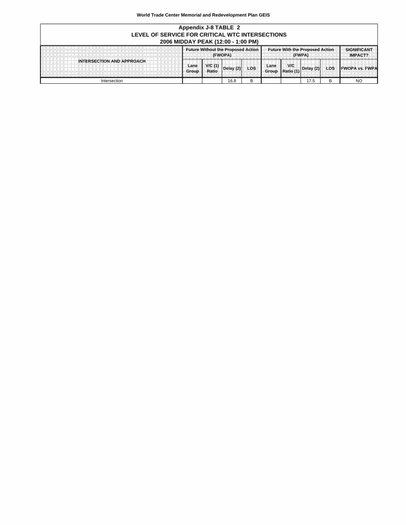
World Trade Center Memorial and Redevelopment Plan GEIS
SIGNIFICANT IMPACT?
Lane Group
V/C (1) Ratio Delay (2) LOS Lane
GroupV/C
Ratio (1) Delay (2) LOS FWOPA vs. FWPA
Appendix J-8 TABLE 2
2006 MIDDAY PEAK (12:00 - 1:00 PM)LEVEL OF SERVICE FOR CRITICAL WTC INTERSECTIONS
Future With the Proposed Action (FWPA)
Future Without the Proposed Action (FWOPA)
INTERSECTION AND APPROACH
Intersection 16.8 B 17.5 B NO
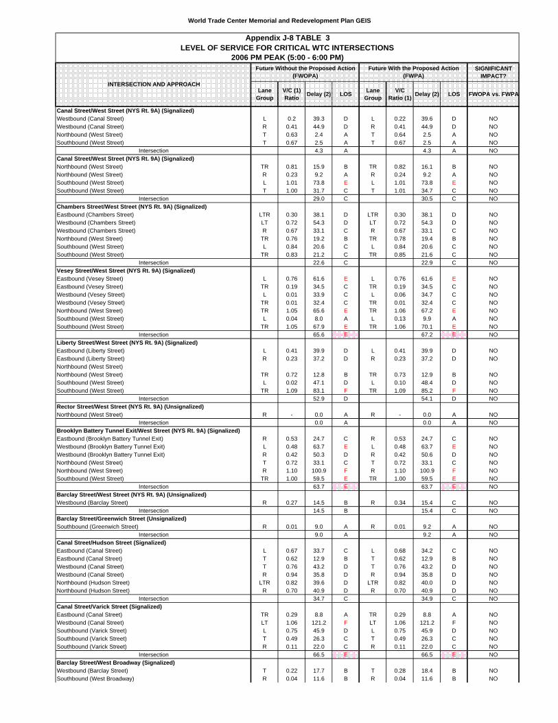
World Trade Center Memorial and Redevelopment Plan GEIS
SIGNIFICANT IMPACT?
Lane Group
V/C (1) Ratio Delay (2) LOS Lane
GroupV/C
Ratio (1) Delay (2) LOS FWOPA vs. FWPA
Canal Street/West Street (NYS Rt. 9A) (Signalized)Westbound (Canal Street) L 0.2 39.3 D L 0.22 39.6 D NOWestbound (Canal Street) R 0.41 44.9 D R 0.41 44.9 D NONorthbound (West Street) T 0.63 2.4 A T 0.64 2.5 A NOSouthbound (West Street) T 0.67 2.5 A T 0.67 2.5 A NO
Intersection 4.3 A 4.3 A NOCanal Street/West Street (NYS Rt. 9A) (Signalized)Northbound (West Street) TR 0.81 15.9 B TR 0.82 16.1 B NONorthbound (West Street) R 0.23 9.2 A R 0.24 9.2 A NOSouthbound (West Street) L 1.01 73.8 E L 1.01 73.8 E NOSouthbound (West Street) T 1.00 31.7 C T 1.01 34.7 C NO
Intersection 29.0 C 30.5 C NOChambers Street/West Street (NYS Rt. 9A) (Signalized)Eastbound (Chambers Street) LTR 0.30 38.1 D LTR 0.30 38.1 D NOWestbound (Chambers Street) LT 0.72 54.3 D LT 0.72 54.3 D NOWestbound (Chambers Street) R 0.67 33.1 C R 0.67 33.1 C NONorthbound (West Street) TR 0.76 19.2 B TR 0.78 19.4 B NOSouthbound (West Street) L 0.84 20.6 C L 0.84 20.6 C NOSouthbound (West Street) TR 0.83 21.2 C TR 0.85 21.6 C NO
Intersection 22.6 C 22.9 C NOVesey Street/West Street (NYS Rt. 9A) (Signalized)Eastbound (Vesey Street) L 0.76 61.6 E L 0.76 61.6 E NOEastbound (Vesey Street) TR 0.19 34.5 C TR 0.19 34.5 C NOWestbound (Vesey Street) L 0.01 33.9 C L 0.06 34.7 C NOWestbound (Vesey Street) TR 0.01 32.4 C TR 0.01 32.4 C NONorthbound (West Street) TR 1.05 65.6 E TR 1.06 67.2 E NOSouthbound (West Street) L 0.04 8.0 A L 0.13 9.9 A NOSouthbound (West Street) TR 1.05 67.9 E TR 1.06 70.1 E NO
Intersection 65.6 E 67.2 E NOLiberty Street/West Street (NYS Rt. 9A) (Signalized)Eastbound (Liberty Street) L 0.41 39.9 D L 0.41 39.9 D NOEastbound (Liberty Street) R 0.23 37.2 D R 0.23 37.2 D NONorthbound (West Street)Northbound (West Street) TR 0.72 12.8 B TR 0.73 12.9 B NOSouthbound (West Street) L 0.02 47.1 D L 0.10 48.4 D NOSouthbound (West Street) TR 1.09 83.1 F TR 1.09 85.2 F NO
Intersection 52.9 D 54.1 D NORector Street/West Street (NYS Rt. 9A) (Unsignalized)Northbound (West Street) R - 0.0 A R - 0.0 A NO
Intersection 0.0 A 0.0 A NOBrooklyn Battery Tunnel Exit/West Street (NYS Rt. 9A) (Signalized)Eastbound (Brooklyn Battery Tunnel Exit) R 0.53 24.7 C R 0.53 24.7 C NOWestbound (Brooklyn Battery Tunnel Exit) L 0.48 63.7 E L 0.48 63.7 E NOWestbound (Brooklyn Battery Tunnel Exit) R 0.42 50.3 D R 0.42 50.6 D NONorthbound (West Street) T 0.72 33.1 C T 0.72 33.1 C NONorthbound (West Street) R 1.10 100.9 F R 1.10 100.9 F NOSouthbound (West Street) TR 1.00 59.5 E TR 1.00 59.5 E NO
Intersection 63.7 E 63.7 E NOBarclay Street/West Street (NYS Rt. 9A) (Unsignalized)Westbound (Barclay Street) R 0.27 14.5 B R 0.34 15.4 C NO
Intersection 14.5 B 15.4 C NOBarclay Street/Greenwich Street (Unsignalized)Southbound (Greenwich Street) R 0.01 9.0 A R 0.01 9.2 A NO
Intersection 9.0 A 9.2 A NOCanal Street/Hudson Street (Signalized)Eastbound (Canal Street) L 0.67 33.7 C L 0.68 34.2 C NOEastbound (Canal Street) T 0.62 12.9 B T 0.62 12.9 B NOWestbound (Canal Street) T 0.76 43.2 D T 0.76 43.2 D NOWestbound (Canal Street) R 0.94 35.8 D R 0.94 35.8 D NONorthbound (Hudson Street) LTR 0.82 39.6 D LTR 0.82 40.0 D NONorthbound (Hudson Street) R 0.70 40.9 D R 0.70 40.9 D NO
Intersection 34.7 C 34.9 C NOCanal Street/Varick Street (Signalized)Eastbound (Canal Street) TR 0.29 8.8 A TR 0.29 8.8 A NOWestbound (Canal Street) LT 1.06 121.2 F LT 1.06 121.2 F NOSouthbound (Varick Street) L 0.75 45.9 D L 0.75 45.9 D NOSouthbound (Varick Street) T 0.49 26.3 C T 0.49 26.3 C NOSouthbound (Varick Street) R 0.11 22.0 C R 0.11 22.0 C NO
Intersection 66.5 E 66.5 E NOBarclay Street/West Broadway (Signalized)Westbound (Barclay Street) T 0.22 17.7 B T 0.28 18.4 B NOSouthbound (West Broadway) R 0.04 11.6 B R 0.04 11.6 B NO
Future Without the Proposed Action (FWOPA)
Appendix J-8 TABLE 3LEVEL OF SERVICE FOR CRITICAL WTC INTERSECTIONS
2006 PM PEAK (5:00 - 6:00 PM)Future With the Proposed Action
(FWPA)INTERSECTION AND APPROACH

World Trade Center Memorial and Redevelopment Plan GEIS
SIGNIFICANT IMPACT?
Lane Group
V/C (1) Ratio Delay (2) LOS Lane
GroupV/C
Ratio (1) Delay (2) LOS FWOPA vs. FWPA
Future Without the Proposed Action (FWOPA)
Appendix J-8 TABLE 3LEVEL OF SERVICE FOR CRITICAL WTC INTERSECTIONS
2006 PM PEAK (5:00 - 6:00 PM)Future With the Proposed Action
(FWPA)INTERSECTION AND APPROACH
Intersection 16.8 B 17.7 B NO
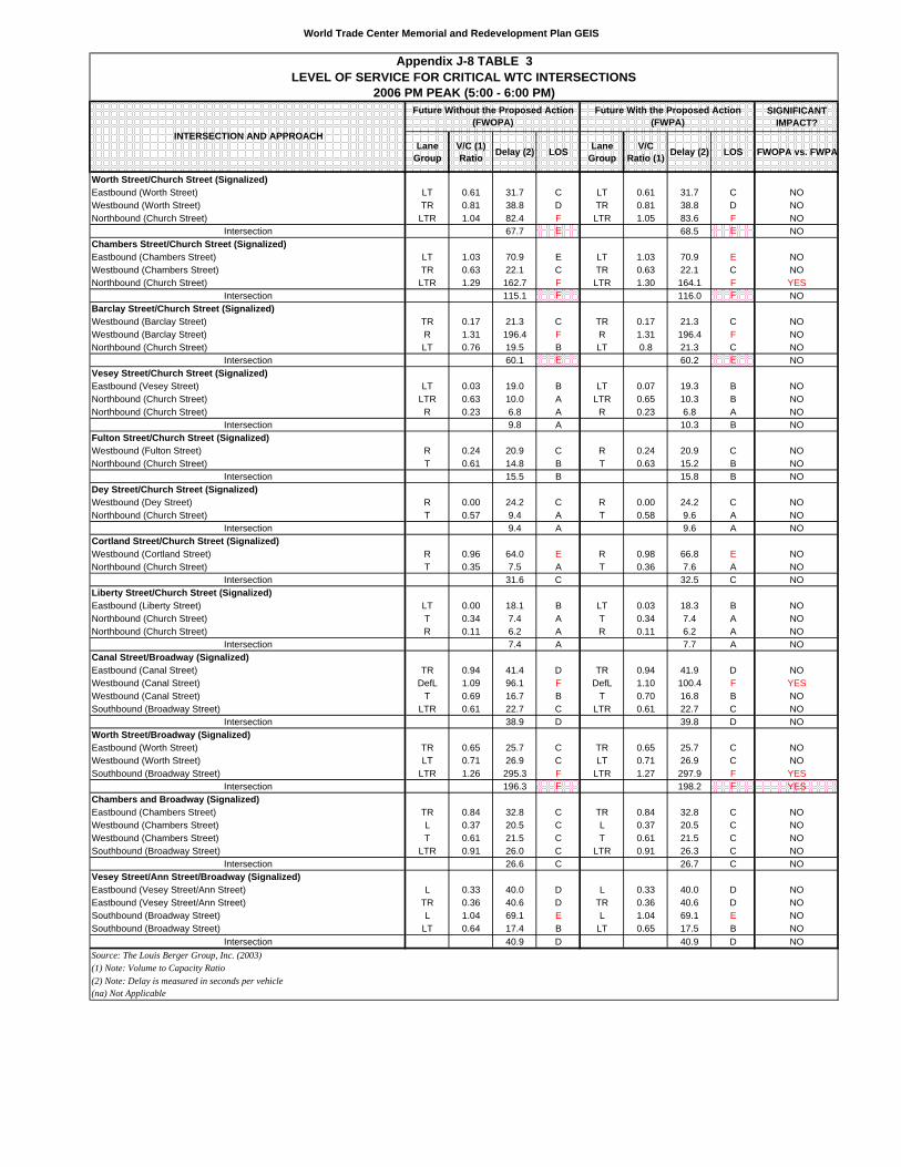
World Trade Center Memorial and Redevelopment Plan GEIS
SIGNIFICANT IMPACT?
Lane Group
V/C (1) Ratio Delay (2) LOS Lane
GroupV/C
Ratio (1) Delay (2) LOS FWOPA vs. FWPA
Future Without the Proposed Action (FWOPA)
Appendix J-8 TABLE 3LEVEL OF SERVICE FOR CRITICAL WTC INTERSECTIONS
2006 PM PEAK (5:00 - 6:00 PM)Future With the Proposed Action
(FWPA)INTERSECTION AND APPROACH
Worth Street/Church Street (Signalized)Eastbound (Worth Street) LT 0.61 31.7 C LT 0.61 31.7 C NOWestbound (Worth Street) TR 0.81 38.8 D TR 0.81 38.8 D NONorthbound (Church Street) LTR 1.04 82.4 F LTR 1.05 83.6 F NO
Intersection 67.7 E 68.5 E NOChambers Street/Church Street (Signalized)Eastbound (Chambers Street) LT 1.03 70.9 E LT 1.03 70.9 E NOWestbound (Chambers Street) TR 0.63 22.1 C TR 0.63 22.1 C NONorthbound (Church Street) LTR 1.29 162.7 F LTR 1.30 164.1 F YES
Intersection 115.1 F 116.0 F NOBarclay Street/Church Street (Signalized)Westbound (Barclay Street) TR 0.17 21.3 C TR 0.17 21.3 C NOWestbound (Barclay Street) R 1.31 196.4 F R 1.31 196.4 F NONorthbound (Church Street) LT 0.76 19.5 B LT 0.8 21.3 C NO
Intersection 60.1 E 60.2 E NOVesey Street/Church Street (Signalized)Eastbound (Vesey Street) LT 0.03 19.0 B LT 0.07 19.3 B NONorthbound (Church Street) LTR 0.63 10.0 A LTR 0.65 10.3 B NONorthbound (Church Street) R 0.23 6.8 A R 0.23 6.8 A NO
Intersection 9.8 A 10.3 B NOFulton Street/Church Street (Signalized)Westbound (Fulton Street) R 0.24 20.9 C R 0.24 20.9 C NONorthbound (Church Street) T 0.61 14.8 B T 0.63 15.2 B NO
Intersection 15.5 B 15.8 B NODey Street/Church Street (Signalized)Westbound (Dey Street) R 0.00 24.2 C R 0.00 24.2 C NONorthbound (Church Street) T 0.57 9.4 A T 0.58 9.6 A NO
Intersection 9.4 A 9.6 A NOCortland Street/Church Street (Signalized)Westbound (Cortland Street) R 0.96 64.0 E R 0.98 66.8 E NONorthbound (Church Street) T 0.35 7.5 A T 0.36 7.6 A NO
Intersection 31.6 C 32.5 C NOLiberty Street/Church Street (Signalized)Eastbound (Liberty Street) LT 0.00 18.1 B LT 0.03 18.3 B NONorthbound (Church Street) T 0.34 7.4 A T 0.34 7.4 A NONorthbound (Church Street) R 0.11 6.2 A R 0.11 6.2 A NO
Intersection 7.4 A 7.7 A NOCanal Street/Broadway (Signalized)Eastbound (Canal Street) TR 0.94 41.4 D TR 0.94 41.9 D NOWestbound (Canal Street) DefL 1.09 96.1 F DefL 1.10 100.4 F YESWestbound (Canal Street) T 0.69 16.7 B T 0.70 16.8 B NOSouthbound (Broadway Street) LTR 0.61 22.7 C LTR 0.61 22.7 C NO
Intersection 38.9 D 39.8 D NOWorth Street/Broadway (Signalized)Eastbound (Worth Street) TR 0.65 25.7 C TR 0.65 25.7 C NOWestbound (Worth Street) LT 0.71 26.9 C LT 0.71 26.9 C NOSouthbound (Broadway Street) LTR 1.26 295.3 F LTR 1.27 297.9 F YES
Intersection 196.3 F 198.2 F YESChambers and Broadway (Signalized)Eastbound (Chambers Street) TR 0.84 32.8 C TR 0.84 32.8 C NOWestbound (Chambers Street) L 0.37 20.5 C L 0.37 20.5 C NOWestbound (Chambers Street) T 0.61 21.5 C T 0.61 21.5 C NOSouthbound (Broadway Street) LTR 0.91 26.0 C LTR 0.91 26.3 C NO
Intersection 26.6 C 26.7 C NOVesey Street/Ann Street/Broadway (Signalized)Eastbound (Vesey Street/Ann Street) L 0.33 40.0 D L 0.33 40.0 D NOEastbound (Vesey Street/Ann Street) TR 0.36 40.6 D TR 0.36 40.6 D NOSouthbound (Broadway Street) L 1.04 69.1 E L 1.04 69.1 E NOSouthbound (Broadway Street) LT 0.64 17.4 B LT 0.65 17.5 B NO
Intersection 40.9 D 40.9 D NOSource: The Louis Berger Group, Inc. (2003)(1) Note: Volume to Capacity Ratio(2) Note: Delay is measured in seconds per vehicle(na) Not Applicable

World Trade Center Memorial and Redevelopment Plan GEIS
J-139 App
Appendix J-9 AIR QUALITY
MOBILE SOURCE ANALYSIS
Mobile source analyses were run for the three scenarios defined in the chapter. The increments were added, where applicable, to increments from the stationary construction modeling results. The totals included background from monitoring stations as well as local background traffic increments that would not be included in background monitors (e.g. Route 9a).
Road dust was included for all PM10 runs, based on the procedure delineated in AP–42 (EPA December, 2003). Silt loading was based on the average daily traffic volumes for Route 9A and Church Street; a silt loading factor of 0.16 g/m2 was used for the construction site entrance. This is the highest loading factor used in New York City, and assumes that access roads would be cleaned regularly.
All other assumptions and procedures for mobile source modeling were identical to those used in analyses in the Air Quality chapter.
As in the analyses in the Air Quality chapter, Neighborhood scale PM2.5 concentrations are conservatively high due to the fact that the minimum distance between the roadway and receptors of 15 meter was used for that analyses, rather than a distance of approximately 30 meters based on one meter per 1,000 vehicles ADT.
STATIONARY SOURCE ANALYSIS
All emission factors for on-site engine emissions were calculated for the normal application of diesel using the draft EPA NONROAD2002a model—the most current data available, based on the engine size and including the loading factor for operation of that type of engine, as presented in Table 1 below. These factors were then scaled down to represent emissions from engines using ULSD and emissions reduction technologies, as follows: 14 percent reduction for ULSD alone; 40 percent for ULSD and diesel oxidation catalysts (DOC); 80 percent for ULSD and diesel particle filters (DPF—the latter was applied only for average emissions estimates for mitigation.) These reductions are based on actual measurements studied by NESCAUM as detailed in Chapter 21.
All emissions were assumed to occur 10 hours per day, from 7 am to noon, and from 1 pm to 6 pm, with a usage percent applied depending on the actual daily hours for the equipment (for example, if a certain engine in needed on the peak day only for 4 hours, the emission factor is scaled by 4/10=0.4).
Emission factors for sources modeled as discrete point sources, such as generators and tower cranes, were calculated based on the above factors, the size of the engine and the daily use percentage as presented above in the construction description, and therefore varied depending on location and construction phase.
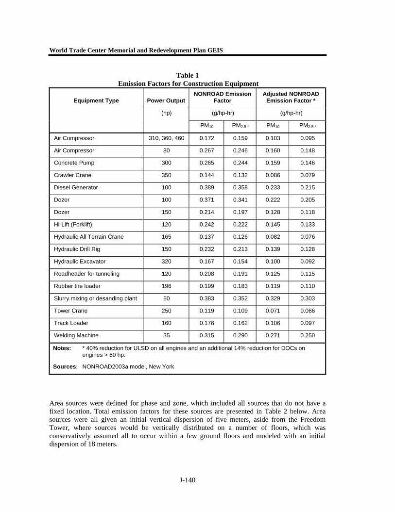
World Trade Center Memorial and Redevelopment Plan GEIS
J-140
Table 1 Emission Factors for Construction Equipment
Power Output NONROAD Emission
Factor Adjusted NONROAD
Emission Factor *
(g/hp-hr) (g/hp-hr)
Equipment Type
(hp)
PM10 PM2.5 * PM10 PM2.5 *
Air Compressor 310, 360, 460 0.172 0.159 0.103 0.095
Air Compressor 80 0.267 0.246 0.160 0.148
Concrete Pump 300 0.265 0.244 0.159 0.146
Crawler Crane 350 0.144 0.132 0.086 0.079
Diesel Generator 100 0.389 0.358 0.233 0.215
Dozer 100 0.371 0.341 0.222 0.205
Dozer 150 0.214 0.197 0.128 0.118
Hi-Lift (Forklift) 120 0.242 0.222 0.145 0.133
Hydraulic All Terrain Crane 165 0.137 0.126 0.082 0.076
Hydraulic Drill Rig 150 0.232 0.213 0.139 0.128
Hydraulic Excavator 320 0.167 0.154 0.100 0.092
Roadheader for tunneling 120 0.208 0.191 0.125 0.115
Rubber tire loader 196 0.199 0.183 0.119 0.110
Slurry mixing or desanding plant 50 0.383 0.352 0.329 0.303
Tower Crane 250 0.119 0.109 0.071 0.066
Track Loader 160 0.176 0.162 0.106 0.097
Welding Machine 35 0.315 0.290 0.271 0.250
Notes: * 40% reduction for ULSD on all engines and an additional 14% reduction for DOCs on engines > 60 hp.
Sources: NONROAD2003a model, New York
Area sources were defined for phase and zone, which included all sources that do not have a fixed location. Total emission factors for these sources are presented in Table 2 below. Area sources were all given an initial vertical dispersion of five meters, aside from the Freedom Tower, where sources would be vertically distributed on a number of floors, which was conservatively assumed all to occur within a few ground floors and modeled with an initial dispersion of 18 meters.
Appendix J. Construction
J-141
Cumulative emissions would clearly be the highest in 2006, as can be seen by the activities planned (see Chapter 21, "Construction".) The peak 24-hour model was based on the 2006 July emissions. The cumulative 2006 July emissions would include the peak emissions from the Proposed Action, and would be insignificantly lower than the cumulative peak calculated for the month of March 2006, as presented in Figure 1 below; these emissions were therefore used to represent both peaks.
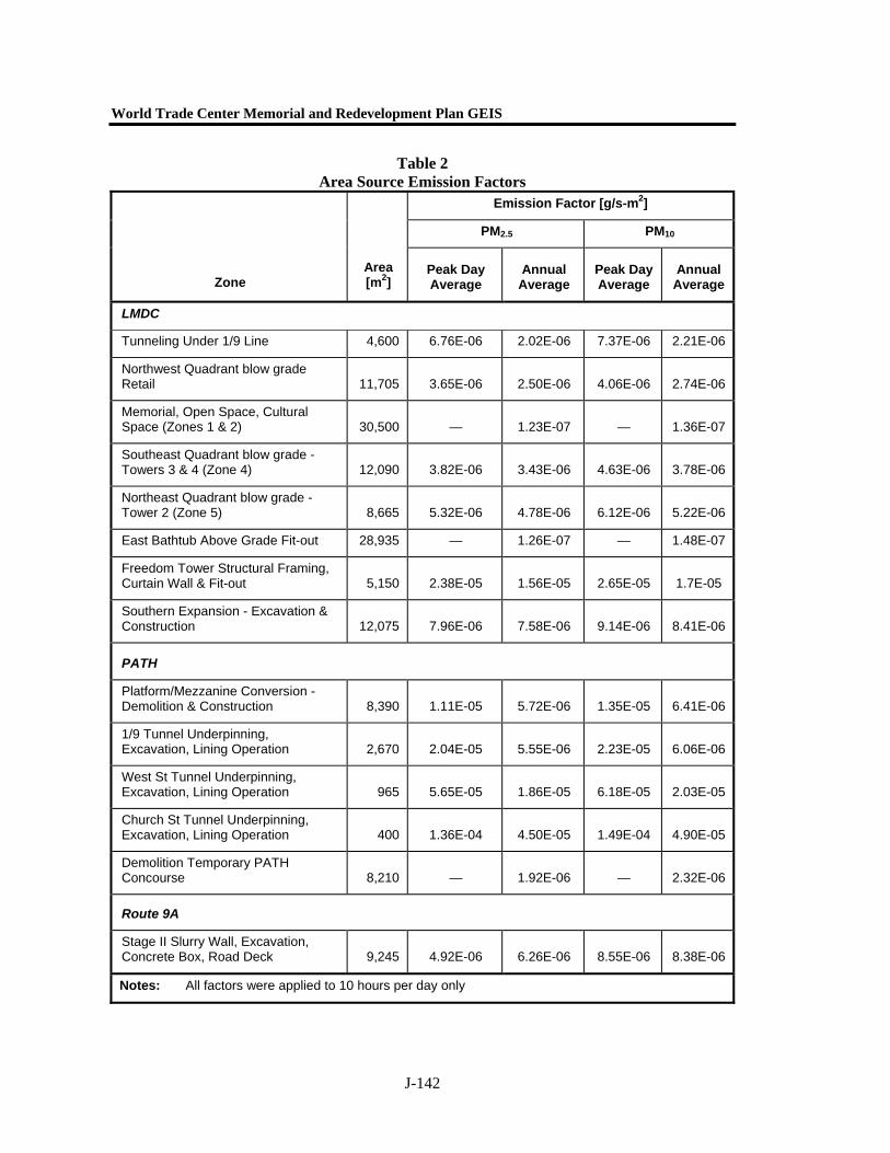
World Trade Center Memorial and Redevelopment Plan GEIS
J-142
Table 2 Area Source Emission Factors
Emission Factor [g/s-m2]
PM2.5 PM10
Zone Area [m2]
Peak Day Average
Annual Average
Peak Day Average
Annual Average
LMDC
Tunneling Under 1/9 Line 4,600 6.76E-06 2.02E-06 7.37E-06 2.21E-06
Northwest Quadrant blow grade Retail 11,705 3.65E-06 2.50E-06 4.06E-06 2.74E-06
Memorial, Open Space, Cultural Space (Zones 1 & 2) 30,500 — 1.23E-07 — 1.36E-07
Southeast Quadrant blow grade - Towers 3 & 4 (Zone 4) 12,090 3.82E-06 3.43E-06 4.63E-06 3.78E-06
Northeast Quadrant blow grade - Tower 2 (Zone 5) 8,665 5.32E-06 4.78E-06 6.12E-06 5.22E-06
East Bathtub Above Grade Fit-out 28,935 — 1.26E-07 — 1.48E-07
Freedom Tower Structural Framing, Curtain Wall & Fit-out 5,150 2.38E-05 1.56E-05 2.65E-05 1.7E-05
Southern Expansion - Excavation & Construction 12,075 7.96E-06 7.58E-06 9.14E-06 8.41E-06
PATH
Platform/Mezzanine Conversion - Demolition & Construction 8,390 1.11E-05 5.72E-06 1.35E-05 6.41E-06
1/9 Tunnel Underpinning, Excavation, Lining Operation 2,670 2.04E-05 5.55E-06 2.23E-05 6.06E-06
West St Tunnel Underpinning, Excavation, Lining Operation 965 5.65E-05 1.86E-05 6.18E-05 2.03E-05
Church St Tunnel Underpinning, Excavation, Lining Operation 400 1.36E-04 4.50E-05 1.49E-04 4.90E-05
Demolition Temporary PATH Concourse 8,210 — 1.92E-06 — 2.32E-06
Route 9A
Stage II Slurry Wall, Excavation, Concrete Box, Road Deck 9,245 4.92E-06 6.26E-06 8.55E-06 8.38E-06
Notes: All factors were applied to 10 hours per day only
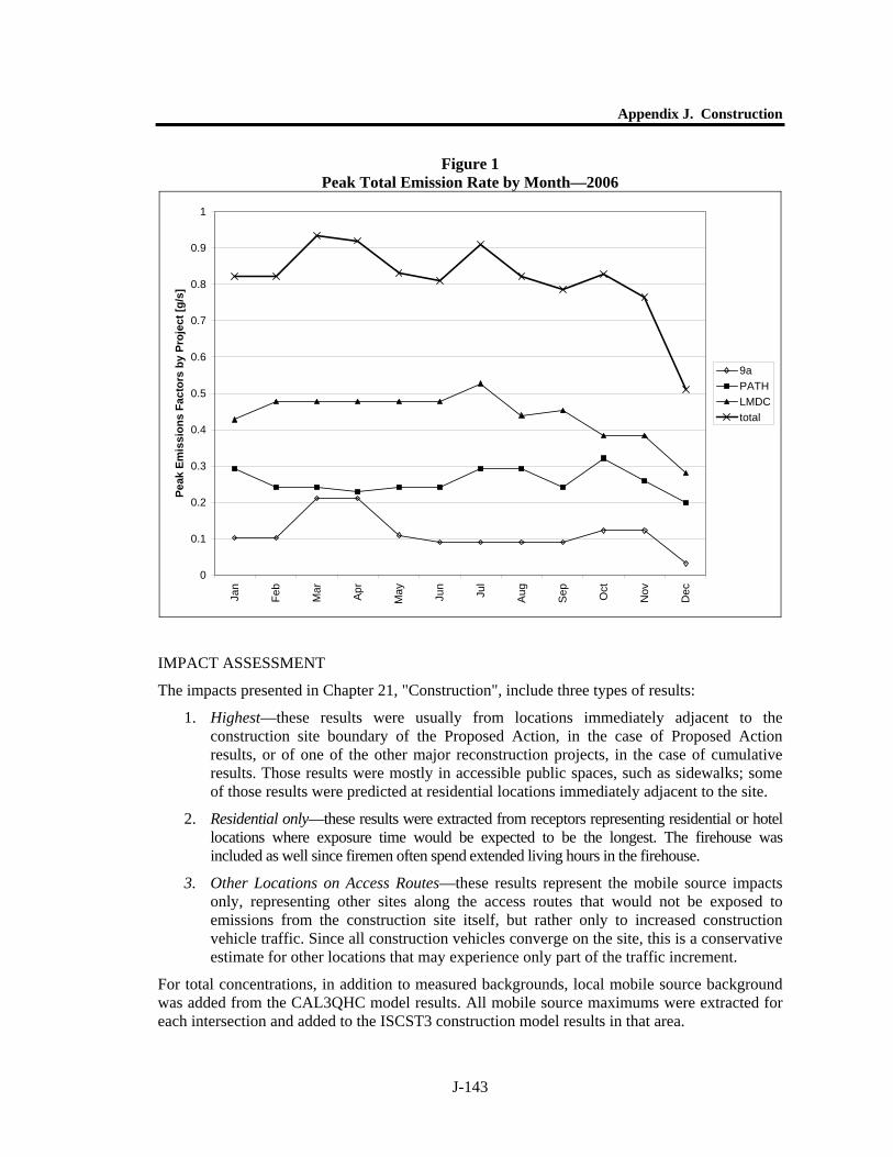
Appendix J. Construction
J-143
Figure 1 Peak Total Emission Rate by Month—2006
0
0.1
0.2
0.3
0.4
0.5
0.6
0.7
0.8
0.9
1
Jan
Feb
Mar Apr
May Jun
Jul
Aug
Sep Oct
Nov
Dec
Peak
Em
issi
ons
Fact
ors
by P
roje
ct [g
/s]
9aPATHLMDCtotal
IMPACT ASSESSMENT
The impacts presented in Chapter 21, "Construction", include three types of results:
1. Highest—these results were usually from locations immediately adjacent to the construction site boundary of the Proposed Action, in the case of Proposed Action results, or of one of the other major reconstruction projects, in the case of cumulative results. Those results were mostly in accessible public spaces, such as sidewalks; some of those results were predicted at residential locations immediately adjacent to the site.
2. Residential only—these results were extracted from receptors representing residential or hotel locations where exposure time would be expected to be the longest. The firehouse was included as well since firemen often spend extended living hours in the firehouse.
3. Other Locations on Access Routes—these results represent the mobile source impacts only, representing other sites along the access routes that would not be exposed to emissions from the construction site itself, but rather only to increased construction vehicle traffic. Since all construction vehicles converge on the site, this is a conservative estimate for other locations that may experience only part of the traffic increment.
For total concentrations, in addition to measured backgrounds, local mobile source background was added from the CAL3QHC model results. All mobile source maximums were extracted for each intersection and added to the ISCST3 construction model results in that area.