Embed Size (px)
Citation preview

ONONDAGA LAKE CAPPING, DREDGING,
HABITAT AND PROFUNDAL ZONE (SMU 8)FINAL DESIGN
PARSONS
P:\Honeywell -SYR\446232 - Cap Design\09 Reports\9.3 Final Design Report\Final to DEC\Appendix flysheets.docx March 5, 2012
APPENDIX L
CAP MATERIAL SPECIFICATIONS


APPENDIX L
CAP MATERIAL SPECIFICATIONS
Prepared for
Prepared by
Anchor QEA, LLC
290 Elwood Davis Road
Liverpool, NY 13088
March 2012

Appendix L – Cap Material Specifications March 2012 Onondaga Lake i 090139-01
TABLE OF CONTENTS
1 INTRODUCTION ................................................................................................................ 1
2 CONSIDERATIONS RELATED TO CAP MATERIAL GRADATIONS .............................. 2
3 SPECIFICATION DEVELOPMENT FOR AGGREGATE MATERIALS .............................. 5
4 AMENDED CAP MATERIALS .......................................................................................... 14
4.1 Granulated Activated Carbon ........................................................................................14
4.2 Siderite ............................................................................................................................14
5 EARTHEN MATERIAL CHEMICAL CRITERIA .............................................................. 16
6 REFERENCES .................................................................................................................... 20
List of Tables
Table 1 Habitat Material and Erosion Protection Layer D50 ............................................. 5
Table 2 Erosion Protection Materials Initial Design D50 by Remediation Area .............. 8
Table 3 Final Design Material Types ................................................................................ 10
Table 4 Armor and Isolation Material Filter Criteria Comparison ................................ 12
Table 5 Unrestricted Use Soil Cleanup Objectives .......................................................... 16
List of Figures
Figure 1 Sand Material Gradations
Figure 2 Gravelly Cobbles and Gravel Material Gradations
Figure 3 Gravel Filter Criteria Comparison
Figure 4 Gravelly Cobbles Filter Criteria Comparison
List of Attachments
Attachment A Earthen Material Specifications
Appendix L – Cap Material Specifications March 2012 Onondaga Lake ii 090139-01
LIST OF ACRONYMS AND ABBREVIATIONS CQAP Construction Quality Assurance Plan
GAC Granulated Activated Carbon
Lake Onondaga Lake
mg/g milligrams per gram
mm millimeters
NYSDEC New York State Department of Environmental Conservation
NYSDOT New York State Department of Transportation
USACE United States Army Corps of Engineers
USCS Unified Soil Classification System
USEPA U.S. Environmental Protection Agency

Appendix L – Cap Material Specifications March 2012 Onondaga Lake 1 090139-01
1 INTRODUCTION
This document presents the process for developing specifications for capping and habitat
materials for the Onondaga Lake (Lake) remediation project. In addition to the conventional
aggregate materials necessary for cap construction, amended cap materials (e.g., Granulated
Activated Carbon [GAC] and siderite) are incorporated into the design of the chemical
isolation layer materials.
Materials to be used in the construction of caps in the Lake and adjacent wetlands can be
categorized into habitat, chemical isolation, and erosion protection materials based on their
function within the overall cap design. For habitat materials, general grain size
characteristics were identified to provide the desired habitat substrate; additional details
regarding habitat material development are included in Section 4.3 and Appendix K of the
Onondaga Lake Capping, Dredging, and Habitat Final Design Report (Final Design).
Similarly, chemical isolation material characteristics were identified to provide the selected
isolation properties (primarily based on porosity) in conjunction with the design mixes of
siderite and GAC. Appendix B of the Final Design provides additional details on the design
of the chemical isolation layer. The general grain size characteristics of erosion protection
materials were selected based on the hydrodynamic and wave conditions expected within
each remediation area as discussed in Appendix D of the Final Design.
In general, the specifications for the capping materials for the Lake and adjacent wetlands
were developed through a series of steps including the following:
Initial design requirements based on habitat objectives and erosion protection
evaluations
Consideration of site-specific design factors
Development of gradation specifications
These steps and the resulting specifications are discussed in detail below.

Appendix L – Cap Material Specifications March 2012 Onondaga Lake 2 090139-01
2 CONSIDERATIONS RELATED TO CAP MATERIAL GRADATIONS
Technical analyses completed as part of the Lake design included the initial development of
general material classifications and mass median particle sizes (D50: diameter at which 50
percent by weight is finer) required by the design. These initial design requirements are
narrowly focused on the material type or D50 particle size and do not include a complete
gradation specification. Therefore, a number of factors (including site-specific factors) were
considered in developing the complete material specifications, including the following:
Local availability of materials: The local availability of cap materials was considered to
minimize transport distances and associated environmental impacts. Furthermore,
use of a local source provides for “just-in-time” deliveries to the project site, which
reduces the required on-site storage requirements. Though not a driver for cap
design, locally available materials were considered when developing gradations so as
not to unreasonably limit material sourcing. All potential influences of local
materials were verified to pass design criteria prior to incorporation in gradation
development.
Material processing effort required to meet specifications: Honeywell has committed
to focus on sustainability for the overall Syracuse portfolio of projects. As part of this
focus, cap material specifications were aimed at minimizing the level of effort
required to produce the materials as well as minimizing the amount of by-product
generated by the processing that would not otherwise be used for the Onondaga Lake
project or other local projects.
Habitat considerations: The potential for cap materials to provide suitable habitat
functionality was also considered during material specification development.
Naturally occurring rounded or run-of-bank material is preferred over crushed rock
to aid in habitat development. In addition, topsoil with an organic matter content
requirement for specified habitat materials is included to provide suitable substrate in
wetland areas and areas of the lake that will be planted.
Cap material placement equipment and limitations: As discussed in Section 4.5 of the
Final Design, the majority of capping materials will be placed using a hydraulic
spreader system. Discussions with the selected contractor regarding the ability to
hydraulically transport the materials without excessive pumping and pipeline issues
lead to identifying an upper size limit (e.g., D100) of approximately 2 to 3 inches in

Considerations Related to Cap Material Gradations
Appendix L – Cap Material Specifications March 2012 Onondaga Lake 3 090139-01
diameter for gravels and sands. Larger diameter materials (e.g., gravelly cobbles and
coarse gravels) will be placed mechanically; therefore, the restriction was not applied
to those materials.
Required quantities: Required quantities of material were reviewed to evaluate the
feasibility for minimizing the total number of material types required. By evaluating
the quantity of materials involved at different design sizes, it was possible to reduce
the total number of specified material types by combining several required sizes
under one specified material. For example, design requirements indicate that several
areas require sand-sized particles with varying median diameters (D50 ranging
between 0.03 and 0.08 inches for these areas). Because the median particle sizes for
these areas were not significantly different, the design requirements for the areas
were combined into a single specification where the specified D50 will be at least 0.08
inches, thereby satisfying the minimum sizing requirements for stability for the range
of required materials.
Well-graded materials: Development of gradations considered the design D50 values
and criteria from the U.S. Army Corps of Engineers (USACE) Engineering Manual
1110-2-2300 - General Design and Construction Considerations for Earth and Rock-
Fill Dams (USACE 2004). In addition, the potential for vertical migration of one
granular material through another (often referred to as “piping”) was considered, as
recommended by the U.S. Environmental Protection Agency (USEPA)/USACE’s
“Guidance for In-Situ Subaqueous Capping of Contaminated Sediments” (Palermo et
al. 1998). The potential for piping can be minimized through the use of well-graded
gradations for the two materials. The compatibility of the two materials in
combination was verified in accordance with geotechnical filter criteria (Terzaghi and
Peck 1967).
Fines content relative to water quality (turbidity): To minimize the potential for
turbidity to impact water quality during material placement, the fines content
(percent passing the U.S. no. 200 sieve) of each material type was considered. Section
3 discusses specification of a range of fines content and a target within that range that
will achieve the objectives of minimizing water quality impacts while maintaining
flexibility in individual loads.

Considerations Related to Cap Material Gradations
Appendix L – Cap Material Specifications March 2012 Onondaga Lake 4 090139-01
Layer thickness and over-placement allowance: The thickness of each layer within
the cap is governed, in part, by the particle sizes of the material comprising that layer
—for example, layer thickness is typically a function of the mass median and
maximum particle sizes (D50 and D100). In addition, an over-placement allowance will
be provided for each layer of the cap to account for placement inaccuracies. The
over-placement allowance will vary for each material based on the D50 and D100.
Based on a general objective to minimize cap thickness, grain size specifications
(especially D100) were developed with consideration of layer thickness and over-
placement allowances.

Appendix L – Cap Material Specifications March 2012 Onondaga Lake 5 090139-01
3 SPECIFICATION DEVELOPMENT FOR AGGREGATE MATERIALS
Table 1 presents a description of the habitat material and the initial design requirements for
erosion protection layer for each remediation area. As noted above, these initial design
requirements form the basis for the material specifications with consideration of several site
and operational factors summarized in Section 2. Remediation areas were divided into
habitat modules representing different water depth ranges, with corresponding grain size and
organic matter content requirements. For erosion protection materials, Table 1 presents the
calculated D50 size requirements based on the design described in Sections 1 and 2 and
described in Appendix D (Armor Layer Design) of the Final Design. Note that in some areas,
habitat material size coincides with that of the erosion protection materials, while other
areas require an additional layer of habitat material over the erosion protection layer to
provide suitable habitat substrate.
Table 1
Habitat Material and Erosion Protection Layer D50
Remediation
Area Habitat Module
Habitat Layer
Material
Description
Erosion
Protection Layer
– Design D50
(inches)
Organic
Matter
Content
(percent)
A 6A Topsoil 1.5 5 to 20
5A Topsoil 1.5 5 to 20
4A Topsoil 1.5 5 to 20
3A (in 2- to 3-foot water depth) Topsoil 1.5 5 to 20
3A (in 3- to 7-foot water depth) Fine Gravel a 0.51 N/A
3B (NMC Channel) Coarse Gravel a 1.0 N/A
2B (NMC Channel) Coarse Gravel a 1.0 N/A
2A (in 7- to 10-foot water depth) Fine Gravel a 0.51 N/A
2A (in 10- to 20-foot water depth) Medium Sand a 0.08 N/A
1 Medium Sand a 0.08 N/A
B 5A Fine Gravel 1.7 N/A
3A (in 2-4 foot water depth) Fine Gravel 1.7 N/A
3A (in 4-7 foot water depth) Fine Gravel a 0.67 N/A
2A (in 7-10 foot water depth) Fine Gravel a 0.2 N/A
2A (in 10- to 20-foot water depth) Medium Sand a 0.03 N/A
1 Medium Sand a 0.03 N/A

Specification Development for Aggregate Materials
Appendix L – Cap Material Specifications March 2012 Onondaga Lake 6 090139-01
Remediation
Area Habitat Module
Habitat Layer
Material
Description
Erosion
Protection Layer
– Design D50
(inches)
Organic
Matter
Content
(percent)
C 8A Fine Gravel 1.9 N/A
5B Fine Gravel 1.9 N/A
5B (Boat Launch Area) Coarse Gravel a 1.9 N/A
3B (in 2- to 4-foot water depth) Fine Gravel a 1.9 N/A
3B (Boat Launch Area) Coarse Gravel a 1.9 N/A
3B (in 4- to 7-foot water depth) Fine Gravel a 0.52 N/A
2A (in 7- to 10-foot water depth) Fine Gravel a 0.3 N/A
2A (in 10- to 20-foot water depth) Medium Sand a 0.08 N/A
1 Medium Sand a 0.08 N/A
D 25-foot buffer b Topsoil 1.9 5 to 20
6A Medium Sand 1.9 N/A
5A Medium Sand 1.9 N/A
3B (in 2- to 4-foot water depth) Medium Sand 1.9 N/A
3B (in 4- to 7-foot water depth) Fine Gravel a 0.52 N/A
2A (in 7- to 10-foot water depth) Fine Gravel a 0.3 N/A
2A (in 10- to 20-foot water depth) Medium Sand a 0.08 N/A
1 Medium Sand a 0.08 N/A
E 25-foot buffer b Topsoil 3.0 5 to 20
6B Coarse Gravel 3.0 N/A
5B Coarse Gravel 3.0 N/A
3B (in 2- to 3-foot water depth) Coarse Gravel 3.0 N/A
3B (in 3- to 7-foot water depth) Gravelly Cobbles a 3.0 N/A
2B Coarse Gravel a 1.1 N/A
2A Fine Gravel a 0.4 N/A
2A (Navigation Channel) Gravelly Cobbles a 3.0 N/A
1 Medium Sand a 0.04 N/A
NMC Spits 6A Topsoil wetlands 5 to 20
9B Topsoil wetlands 5 to 20
WB 1-8
Connected
Wetland
6A Topsoil wetlands 5 to 20
5A Topsoil wetlands 5 to 20

Specification Development for Aggregate Materials
Appendix L – Cap Material Specifications March 2012 Onondaga Lake 7 090139-01
Remediation
Area Habitat Module
Habitat Layer
Material
Description
Erosion
Protection Layer
– Design D50
(inches)
Organic
Matter
Content
(percent)
WBB
Outboard
Area
6A Topsoil wetlands 5 to 20
5A Topsoil wetlands 5 to 20
3A Topsoil wetlands 5 to 20
8A Topsoil wetlands 5 to 20
9B Topsoil wetlands 5 to 20
Notes: N/A = not applicable NMC = Ninemile Creek WB = Wastebed WBB = Wastebed B a. Habitat layer and erosion protection layer will be comprised of the same material b. 25-foot buffer – Habitat substrate from the shoreline to 25 feet offshore will be topsoil along Remediation Area D and the Wastebed B Outboard Area. Wetlands – In the adjacent wetlands, the additional erosion protection that will be provided by the wetland vegetation was taken into consideration, resulting in an erosion protection layer of Coarse Gravel (Type B) with a minimum erosion protection layer thickness in the wetlands of 4.5 inches, as detailed in Appendix D
To advance the development of the specifications and reduce the required number of
material types for cap construction, design sizes for the erosion protection material from
Table 1 were grouped into similar size categories based on Unified Soil Classification System
(USCS) material classifications. Table 2 presents a summary of the calculated D50 for the
erosion protection layer material in each remediation area (from Table 1), with materials
having similar required particle sizes grouped into four general categories: sand, fine gravel,
coarse gravel, and gravelly cobbles.

Specification Development for Aggregate Materials
Appendix L – Cap Material Specifications March 2012 Onondaga Lake 8 090139-01
Table 2
Erosion Protection Materials Initial Design D50 by Remediation Area
Material Type Capping Area Design Calculated D50a (inches)
Sand
Remediation Area A 0.08
Remediation Area B 0.03
Remediation Area C 0.08
Remediation Area D 0.08
Remediation Area E 0.04
Remediation Area F 0.08
Fine Gravel
Remediation Area A 0.51
Remediation Area B 0.67
Remediation Area C 0.52
Remediation Area D 0.52
Remediation Area E 0.4
Remediation Area F 0.51
Coarse Gravel
Remediation Area A 1.5
Remediation Area B 1.7
Remediation Area C 1.9
Remediation Area D 1.9
Remediation Area E 1.1
Remediation Area F -
Gravelly
Cobbles
Remediation Area A -
Remediation Area B -
Remediation Area C -
Remediation Area D -
Remediation Area E 3.0
Remediation Area F -
Note: a. Design calculated D50 sizing indicated is a minimum size necessary for
material stability; specifications will require material to have D50 greater than or equal to values shown.
After grouping materials into the categories listed in Table 2, the largest design D50 size for
each category was selected for use in specification development. The selection of the
maximum design D50 for each material type allows the use of one material specification to
cover the range of design conditions found throughout the various remediation areas,
thereby reducing the required number of material types and associated material processing.

Specification Development for Aggregate Materials
Appendix L – Cap Material Specifications March 2012 Onondaga Lake 9 090139-01
Based on a review of design conditions outlined in Section 2, it was determined that
additional material subdivisions would be required for sand material and coarse gravel
material. The sand category was subdivided into two material types (i.e., medium sand and
gravelly sand) based on geotechnical filter criteria consideration when used as isolation
material underlying the erosion protection material. Specifically, use of the gravelly sand
planned for the chemical isolation layer in Remediation Area E will minimize the potential
for the sand portion of the chemical isolation layer material to wash out through the larger
void spaces of the overlying gravelly cobble material. The medium sand will be used for the
chemical isolation material in all other remediation areas, as well as for the habitat layer
where sand is the required material type (see Table 1).
Similar to the sand category, the coarse gravel category was further subdivided into two
types (A and B) based on the ability to hydraulically place the material. Approximately 80
percent of the total coarse gravel volume required for the project is located in Remediation
Area E and requires a D50 of at least 1.1 inches; the remaining 20 percent requires a D50 of
approximately 1.5 inches to 2 inches. By developing two separate specifications for coarse
gravel (types A and B), the majority of the coarse gravel material (that with the smaller
particle size) could likely be hydraulically placed, reducing cost and schedule implications of
mechanical placement required of the larger materials.
The selected D50 sizing for each erosion protection material type is presented in Table 3.

Specification Development for Aggregate Materials
Appendix L – Cap Material Specifications March 2012 Onondaga Lake 10 090139-01
Table 3
Final Design Material Types
Material Type Capping Area Required D50 a (inches)
Medium Sand Remediation Areas A, B, C, D,E, and F 0.08
Gravelly Sand Remediation Area E, DOT turnaround
area steep slope 0.13 b
Fine Gravel Remediation Areas A, B, C, D, E, and F 0.67
Coarse Gravel (Type A) Remediation Areas A, B, C, and D 1.9
Coarse Gravel (Type B) Remediation Area E 1.1
Gravelly Cobbles Remediation Area E 3.0
Notes: a. Required D50 based on largest required D50 from initial design analyses for each applicable
remediation area (see tables 1 and 2). D50 sizing indicated is a minimum sizing, specifications will require material to have D50 greater than or equal to values shown.
b. Required D50 for gravelly sand based on geotechnical filter criteria (see below).
The selected D50 for each material type listed in Table 3 was compared against standard U.S.
sieve sizes to select a standard sieve size to use in the specification. The specification was
then developed around this selected sieve size such that no more than 50 percent (by weight)
in the design gradation would pass this sieve, ensuring that material meeting the
specification would have a D50 equal to or larger than the selected sieve size. A range was
then included on the selected sieve size (e.g., 30 to 50 percent passing), allowing for some
natural variation in the gradation specification while still ensuring that the required D50
would be achieved.
An upper bound maximum particle size (D100) for each material type was selected based on
design considerations such as hydraulic transport and overplacement tolerances, as discussed
in Section 2. For example, the gravelly cobble specification includes a maximum stone size
of 6 inches to maintain a 6-inch over-placement allowance. The maximum particle sizes for
the coarse gravels (Type A and Type B) were selected to prevent excessive larger material in
the specification while still allowing a broad range of materials to meet the specification (i.e.,
allowing a naturally occurring bank run material with minimal processing). The maximum
particle size for the remainder of capping materials was limited to 2 to 3 inches to allow
hydraulic transport and placement of the material.
Specification Development for Aggregate Materials
Appendix L – Cap Material Specifications March 2012 Onondaga Lake 11 090139-01
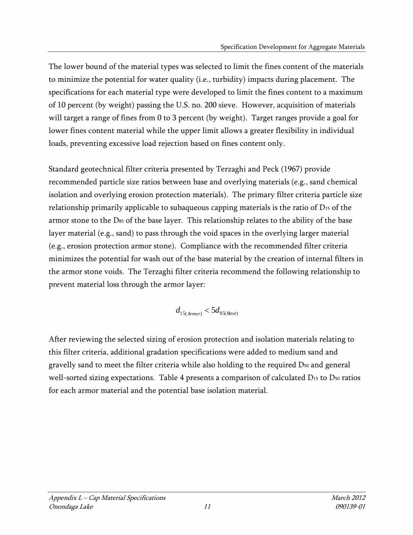
The lower bound of the material types was selected to limit the fines content of the materials
to minimize the potential for water quality (i.e., turbidity) impacts during placement. The
specifications for each material type were developed to limit the fines content to a maximum
of 10 percent (by weight) passing the U.S. no. 200 sieve. However, acquisition of materials
will target a range of fines from 0 to 3 percent (by weight). Target ranges provide a goal for
lower fines content material while the upper limit allows a greater flexibility in individual
loads, preventing excessive load rejection based on fines content only.
Standard geotechnical filter criteria presented by Terzaghi and Peck (1967) provide
recommended particle size ratios between base and overlying materials (e.g., sand chemical
isolation and overlying erosion protection materials). The primary filter criteria particle size
relationship primarily applicable to subaqueous capping materials is the ratio of D15 of the
armor stone to the D85 of the base layer. This relationship relates to the ability of the base
layer material (e.g., sand) to pass through the void spaces in the overlying larger material
(e.g., erosion protection armor stone). Compliance with the recommended filter criteria
minimizes the potential for wash out of the base material by the creation of internal filters in
the armor stone voids. The Terzaghi filter criteria recommend the following relationship to
prevent material loss through the armor layer:
)(85)(15 5 BaseArmordd
After reviewing the selected sizing of erosion protection and isolation materials relating to
this filter criteria, additional gradation specifications were added to medium sand and
gravelly sand to meet the filter criteria while also holding to the required D50 and general
well-sorted sizing expectations. Table 4 presents a comparison of calculated D15 to D50 ratios
for each armor material and the potential base isolation material.

Specification Development for Aggregate Materials
Appendix L – Cap Material Specifications March 2012 Onondaga Lake 12 090139-01
Table 4
Armor and Isolation Material Filter Criteria Comparison
Armor Material
Armor D15 Range a
(inches) Base (Isolation)
Material
Base D85 Range a
(inches) D15/D85
Max Ratio b Min Max Min Max
Gravelly
Cobbles 0.025 0.75
Gravelly Sand 0.625 1.2 1.2
Medium Sand 0.21 0.3 3.6
Coarse Gravel
Type A 0.007 0.75
Gravelly Sand 0.625 1.2 1.2
Medium Sand 0.21 0.3 3.6
Coarse Gravel
Type B 0.0065 0.5
Gravelly Sand 0.625 1.2 0.8
Medium Sand 0.21 0.3 2.4
Fine Gravel 0.006 0.05 Gravelly Sand 0.625 1.2 0.08
Medium Sand 0.21 0.3 0.24
Notes: a. D15 and D85 size ranges, where not specified, were selected based on standard geotechnical
gradation curves developed from the specified gradation. b. Terzaghi criteria recommends a D15/D85 ratio of less than 5 to prevent loss of base material through
armor void spaces. Maximum ratio applies to the worst case scenario comparison of the maximum armor D15 compared to the minimum base D85.
Figures 1 and 2 illustrate the design gradations; Figures 3 and 4 illustrate the D15 to D85 ratio
relationships between the armor materials and underlying sand chemical isolation materials.
There are two additional materials that are also specified. An armor stone will be placed
along the steep slope of the New York State Department of Transportation (NYSDOT)
Turnaround Area to physically isolate the slag material. The armor cap over the isolation
layer will consist of a layer of gravelly sand material as a bedding layer beneath the armor
stone, to the extent possible, and an armor stone ranging in diameter size of 4 to 18 inches.
Additionally, material will be placed along a portion of the surf zone of Remediation Area B
to address erosion of Solvay waste material along the shoreline of WB 1-8. Shoreline
stabilization material consisting of a graded gravel, bank-run material will be placed at an
average thickness of approximately 1.5 feet from elevation 365 feet to 362.5 feet (upland
from the shoreline). Shoreline stabilization material consisting of Coarse Gravel (Type B)

Specification Development for Aggregate Materials
Appendix L – Cap Material Specifications March 2012 Onondaga Lake 13 090139-01
will be placed at an average thickness of approximately 6 inches from elevation 362.5 feet to
360 feet (within the Lake).
Attachment A presents material specifications and gradation for each material type based on
the requirements and considerations detailed above.

Appendix L – Cap Material Specifications March 2012 Onondaga Lake 14 090139-01
4 AMENDED CAP MATERIALS
Isolation materials utilized in cap construction will include amendment materials blended
with the cap layer to provide appropriate isolation properties. Amendment materials include
GAC and siderite for the chemical isolation layer. Application of these materials is based on
an addition of specified quantities by weight per square foot of cap construction. Additional
details regarding amendment rates and design are presented in Appendix B and Appendix I
of the Final Design.
4.1 Granulated Activated Carbon
The GAC for use in the cap chemical isolation layer will be Calgon F400 or equivalent. The
specifications that a supplier will have to meet, whether it is Calgon or another supplier, are
the following Calgon F400 specifications:
The material shall be virgin condition
The base material must be bituminous coal
Steam will be used as its activation method
A minimum iodine number of 1,000 milligrams per gram (mg/g)
A maximum moisture of 2 percent by weight
A minimum abrasion number of 75
An effective size of 0.55 to 0.75 millimeters (mm)
A maximum uniformity coefficient of 1.9
No more than 5 percent by weight greater than 12 mesh (1.7 mm)
No more than 4 percent by weight less than 40 mesh (0.42 mm)
The size of the GAC particles (specified in the last two bullets above) will be subject to
change following NYSDEC review and approval in the event that the GAC is not vertically
well-mixed throughout the sand isolation layer.
4.2 Siderite
The siderite for use in the cap chemical isolation layer will be granular, composed of
approximately sand-sized particles, and will meet the following specifications:
The base material will be a siderite ore

Amended Cap Materials
Appendix L – Cap Material Specifications March 2012 Onondaga Lake 15 090139-01
Gradations will conform to the following specifications:
U.S. Standard Sieve Size Percent Passing (by weight)
U.S. No. 4 95 to 100
U.S. No. 30 0 to 5
The target ferrous carbonate content will be 74 percent by weight. If the ferrous
carbonate content is less than 74 percent by weight, then the siderite dosing in the
sediment cap will be adjusted as appropriate. The method for verifying the ferrous
carbonate will be provided independently following additional consultation and
discussions with the selected siderite supplier.

Appendix L – Cap Material Specifications March 2012 Onondaga Lake 16 090139-01
5 EARTHEN MATERIAL CHEMICAL CRITERIA
Prior to the procurement of capping materials, borrow sources will be inspected and the
materials characterized to ensure compliance with the specifications presented in
Attachment A. Selected borrow sources will also be subject to materials testing requirements
performed routinely throughout construction to verify continued compliance with project
specifications. Suitable representative samples and test reports will be submitted to and
approved prior to delivery of materials to the job site. The frequency and detailed
procedures for sampling and analysis of cap materials will be provided in the Onondaga Lake
Construction Quality Assurance Plan (CQAP).
Sampling will include standard geotechnical analyses (e.g., grain size, moisture content, and
bulk density) in addition to chemical testing. Chemical testing will be performed to confirm
that the materials comply with the Unrestricted Use Soil Cleanup Objectives listed in
NYSDEC 6 NYCRR Part 375 (summarized in Table 5). Exceedance of any single chemical
compound limit will mean that the entire material batch will be rejected unless subsequent
testing on sub-sets of the batch demonstrates compliance with the criteria.
Table 5
Unrestricted Use Soil Cleanup Objectives
Contaminant
Unrestricted Use Criteria
(parts per million)
Metals
Arsenic 13
Barium 350
Beryllium 7.2
Cadmium 2.5
Chromium, hexavalent 1
Chromium, trivalent 30
Copper 50
Total Cyanide 27

Earthen Material Chemical Criteria
Appendix L – Cap Material Specifications March 2012 Onondaga Lake 17 090139-01
Contaminant
Unrestricted Use Criteria
(parts per million)
Lead 63
Manganese 1600
Total Mercury 0.18
Nickel 30
Selenium 3.9
Silver 2
Zinc 109
PCBs/Pesticides
2,4,5-TP Acid (Silvex)
3.8
4,4’-DDE 0.0033
4,4’-DDT 0.0033
4,4’-DDD 0.0033
Aldrin 0.005
alpha-BHC
0.02
beta-BHC
0.036
Chlordane (alpha)
0.094
delta-BHC 0.04
Dibenzofuran 7
Dieldrin 0.005
Endosulfan I 2.4
Endosulfan II 2.4
Endosulfan sulfate 2.4
Endrin 0.014
Heptachlor 0.042
Lindane 0.1
Polychlorinated biphenyls 0.1

Earthen Material Chemical Criteria
Appendix L – Cap Material Specifications March 2012 Onondaga Lake 18 090139-01
Contaminant
Unrestricted Use Criteria
(parts per million)
Semivolatile Organic Compounds
Acenaphthene 20
Acenapthylene 100
Anthracene 100
Benz(a)anthracene 1
Benzo(a)pyrene 1
Benzo(b)fluoranthene 1
Benzo(g,h,i)perylene 100
Benzo(k)fluoranthene 0.8
Chrysene 1
Dibenz(a,h)anthracene f 0.33
Fluoranthene 100
Fluorene 30
Indeno(1,2,3-cd)pyrene 0.5
m-Cresol 0.33
Naphthalene 12
o-Cresol 0.33
p-Cresol 0.33
Pentachlorophenol 0.8
Phenanthrene
100
Phenol 0.33
Pyrene
100
Volatile Organic Compounds
1,1,1-Trichloroethane
0.68
1,1-Dichloroethane
0.27
1,1-Dichloroethene
0.33
1,2-Dichlorobenzene
1.1

Earthen Material Chemical Criteria
Appendix L – Cap Material Specifications March 2012 Onondaga Lake 19 090139-01
Contaminant
Unrestricted Use Criteria
(parts per million)
1,2-Dichloroethane 0.02
cis -1,2-Dichloroethene
0.25
trans-1,2-Dichloroethene
0.19
1,3-Dichlorobenzene
2.4
1,4-Dichlorobenzene
1.8
1,4-Dioxane 0.1
Acetone
0.05
Benzene
0.06
n-Butylbenzene
12
Carbon tetrachloride
0.76
Chlorobenzene
1.1
Chloroform
0.37
Ethylbenzene
1
Hexachlorobenzene 0.33
Methyl ethyl ketone
0.12
Methyl tert-butyl ether
0.93
Methylene chloride
0.05
n - Propylbenzene
3.9
sec-Butylbenzene
11
tert-Butylbenzene
5.9
Tetrachloroethene
1.3
Toluene 0.7
Trichloroethene 0.47
1,2,4-Trimethylbenzene 3.6
1,3,5-Trimethylbenzene 8.4
Vinyl chloride 0.02
Xylene (mixed) 0.26

Appendix L – Cap Material Specifications March 2012 Onondaga Lake 20 090139-01
6 REFERENCES
Palermo, M., S. Maynord, J. Miller, and D. Reible, 1998. Guidance for In-Situ Subaqueous
Capping of Contaminated Sediments, EPA 905-B96-004, Great Lakes National
Program Office, Chicago, IL.
Terzaghi, K. and R. B. Peck, 1967. Soil Mechanics in Engineering Practice, 2nd ed., John
Wiley and Sons, New York.
United States Army Corps of Engineers (USACE), 2004. Engineering and Design – General
Design and Construction Considerations for Earth and Rock-Fill Dams. Engineering
Manual EM 1110-2-2300. July 30, 2004.

FIGURES

Figure 1 Sand Material Gradations
Cap Material Specifications Onondaga Lake
0
10
20
30
40
50
60
70
80
90
100
0.0010.010.1110100
Perc
ent P
assi
ng
Grain Size in inches
Gravelly Sand
Medium Sand
#4
#10
#40
#200
3/4
in.
2 in
.
4 in
.

Figure 2 Gravelly Cobbles and Gravel Material Gradations
Cap Material Specifications Onondaga Lake
0
10
20
30
40
50
60
70
80
90
100
0.0010.010.1110100
Perc
ent P
assi
ng
Grain Size in inches
Gravelly Cobbles
Coarse Gravel Type A
Coarse Gravel Type B
Fine Gravel
#4
#10
#40
#200
3/4
in.
2 in
.
4 in
.

Figure 3 Gravel Filter Criteria Comparison
Cap Material Specifications Onondaga Lake
D85(base) = 0.21 5*D85(base) = 1.05
D15(armor) < 5*D85(base)
0
10
20
30
40
50
60
70
80
90
100
0.0010.010.1110100
Perc
ent P
assi
ng
Grain Size in inches
Coarse Gravel Type A
Coarse Gravel Type B
Fine Gravel
Medium Sand
#4
#10
#40
#200
3/4
in.
2 in
.
4 in
.
The red dashed lines show that the D15(armor) is less than 5 times the D85(base)
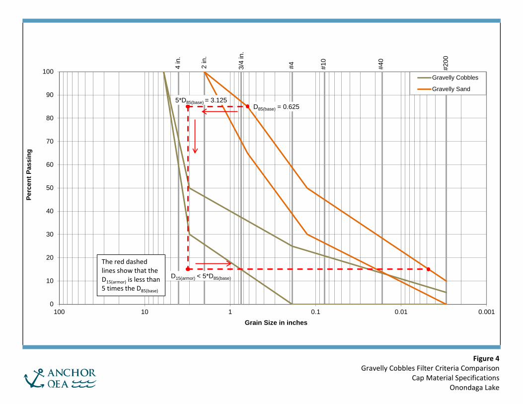
Figure 4 Gravelly Cobbles Filter Criteria Comparison
Cap Material Specifications Onondaga Lake
D85(base) = 0.625
D15(armor) < 5*D85(base)
5*D85(base) = 3.125
0
10
20
30
40
50
60
70
80
90
100
0.0010.010.1110100
Perc
ent P
assi
ng
Grain Size in inches
Gravelly Cobbles
Gravelly Sand
#4
#10
#40
#200
3/4
in.
2 in
.
4 in
.
The red dashed lines show that the D15(armor) is less than 5 times the D85(base)
ATTACHMENT A EARTHEN MATERIAL SPECIFICATIONS

Attachment A
Attachment A – Earthen Material Specifications March 2012 Onondaga Lake 1 090139-01
All materials shall be of the quality, size, shape, and gradation or equal to that manufacture
as specified herein. Materials will be procured from an approved borrow source in
accordance with the Onondaga Lake Construction Quality Assurance Plan.
Gravelly Cobbles
Gravelly cobble material will consist of naturally occurring stone, gravel, screened gravel or
run-of-bank material. Screened gravel or bank run material will consist of uncrushed
particles. Gravelly cobble material designed below the top 12 inches of the cap may be a
crushed product. Crushed stone and gravel will consist of clean, durable, sharp-angled rock
fragments of uniform quality. Gradations must conform to the table below.
U.S. Standard Sieve Size Percent Passing (by weight)
6 inch 100
3 inch 30 to 50
U.S. No. 4 0 to 25
U.S. No. 200 0 to 5 (0 to 3 preferred)
Coarse Gravel – Type A
Coarse Gravel material will consist of naturally occurring screened or run-of-bank gravel or
other acceptable granular material. Crushed stone would be acceptable when used below the
top 12 inches of the cap. Gradations must conform to the table below.
U.S. Standard Sieve Size Percent Passing (by weight)
4 inch 100
2 inch 30 to 50
3/4 inch >15
U.S. No. 200 0 to 10 (0 to 3 preferred)
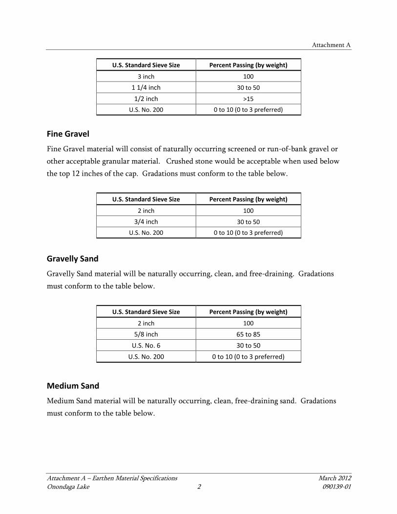
Coarse Gravel – Type B
Coarse Gravel material will consist of naturally occurring screened or run-of-bank gravel or
other acceptable granular material. Gradations must conform to the table below.
Attachment A
Attachment A – Earthen Material Specifications March 2012 Onondaga Lake 2 090139-01
U.S. Standard Sieve Size Percent Passing (by weight)
3 inch 100
1 1/4 inch 30 to 50
1/2 inch >15
U.S. No. 200 0 to 10 (0 to 3 preferred)
Fine Gravel
Fine Gravel material will consist of naturally occurring screened or run-of-bank gravel or
other acceptable granular material. Crushed stone would be acceptable when used below
the top 12 inches of the cap. Gradations must conform to the table below.
U.S. Standard Sieve Size Percent Passing (by weight)
2 inch 100
3/4 inch 30 to 50
U.S. No. 200 0 to 10 (0 to 3 preferred)
Gravelly Sand
Gravelly Sand material will be naturally occurring, clean, and free-draining. Gradations
must conform to the table below.
U.S. Standard Sieve Size Percent Passing (by weight)
2 inch 100
5/8 inch 65 to 85
U.S. No. 6 30 to 50
U.S. No. 200 0 to 10 (0 to 3 preferred)
Medium Sand
Medium Sand material will be naturally occurring, clean, free-draining sand. Gradations
must conform to the table below.

Attachment A
Attachment A – Earthen Material Specifications March 2012 Onondaga Lake 3 090139-01
U.S. Standard Sieve Size Percent Passing (by weight)
3/8 inch 95 to 100
U.S. No. 10 30 to 60
U.S. No. 200 0 to 10 (0 to 3 preferred)
Topsoil
Topsoil shall be natural or manufactured, friable, and fertile soil that meets the U.S.
Department of Agriculture (USDA) basic soil texture classes of loam, silt loam, or sandy loam
to be recovered from the A horizon of an in-place soil. Topsoil shall be capable of sustaining
healthy plant life and be reasonably free of subsoil, heavy or stiff clay, brush, roots, weeds,
other objectionable plant matter, foreign material, stones larger than 4 inches in greatest
dimension, and any other materials unsuitable or harmful for plant growth. Topsoil as
delivered to the site or stockpiled shall meet the following requirements:
Gradations conforming to the table below:
U.S. Standard Sieve Size Percent Passing (by weight)
4 inch 100
1 inch 85 to 100
¼ inch 65 to 100
U.S. No. 200 15 to 80
The 2 micron particle size shall not be greater than 20 percent of the total sample
mass, as determined by hydrometer analysis.
pH between 5.5 and 7.6
Percent organic matter:
For wetland modules, topsoil shall contain greater than or equal to 5 percent and
less than 20 percent organic matter as determined by loss on ignition of moisture-
free samples dried at 100° to 110° Celsius. A mean value of approximately 7.5
percent organic matter will be targeted in the wetland areas.
For non-wetland areas (planted areas within the lake and upland modules with
topsoil), topsoil shall contain greater than 5 percent and less than 20 percent

Attachment A
Attachment A – Earthen Material Specifications March 2012 Onondaga Lake 4 090139-01
organic matter as determined by loss of ignition of moisture-free samples dried at
100° to 110° Celsius.
Contain no nuisance weeds including seeds, stems, or rhizomes of Purple Loosestrife,
Phragmites, Japanese Knotweed, or any plants on the Federal Noxious Weeds list.
NYSDOT Turnaround Area Shoreline Armor Stone
The armor stone used for the NYSDOT Turnaround Area shoreline will be riprap
conforming to the following gradations:
Stone Size Percent Passing (by weight)
Heavier than 100 pounds 50 to 100
Larger than 12 inches 50 to 100
Larger than 18 inches 0
Smaller than 4 inches 0 to 10
Remediation Area B Graded Gravel
The graded gravel to be used for the Remediation Area B shoreline stabilization between an
elevation of 362.5 and 365 feet will be screened or run-of-bank gravel or other acceptable
granular material. The material shall contain greater than 0.5 percent but less than 6 percent
organic content by weight as determined using ASTM D2974. Gradations must conform to
the table below:
U.S. Standard Sieve Size Percent Passing (by weight)
8 inch 100
4 inch 80 to 100
¼ inch 30 to 75
No. 40 15 to 60
U.S. No. 200 Less than or equal to 25
Below elevation 362.5 feet, coarse gravel will be used for the shoreline stabilization material.

Attachment A
Attachment A – Earthen Material Specifications March 2012 Onondaga Lake 5 090139-01
Outfall Scour Protection
The stone used for the outfalls will be riprap conforming to the following gradations (based
on the NYSDOT Standard Specification for Medium Stone Filling specified in Figure 620-1):
Stone Size Percent Passing (by weight)
Heavier than 100 pounds 50 to 100
Smaller than 6 inches 0 to 10