Embed Size (px)
Citation preview
Appendix
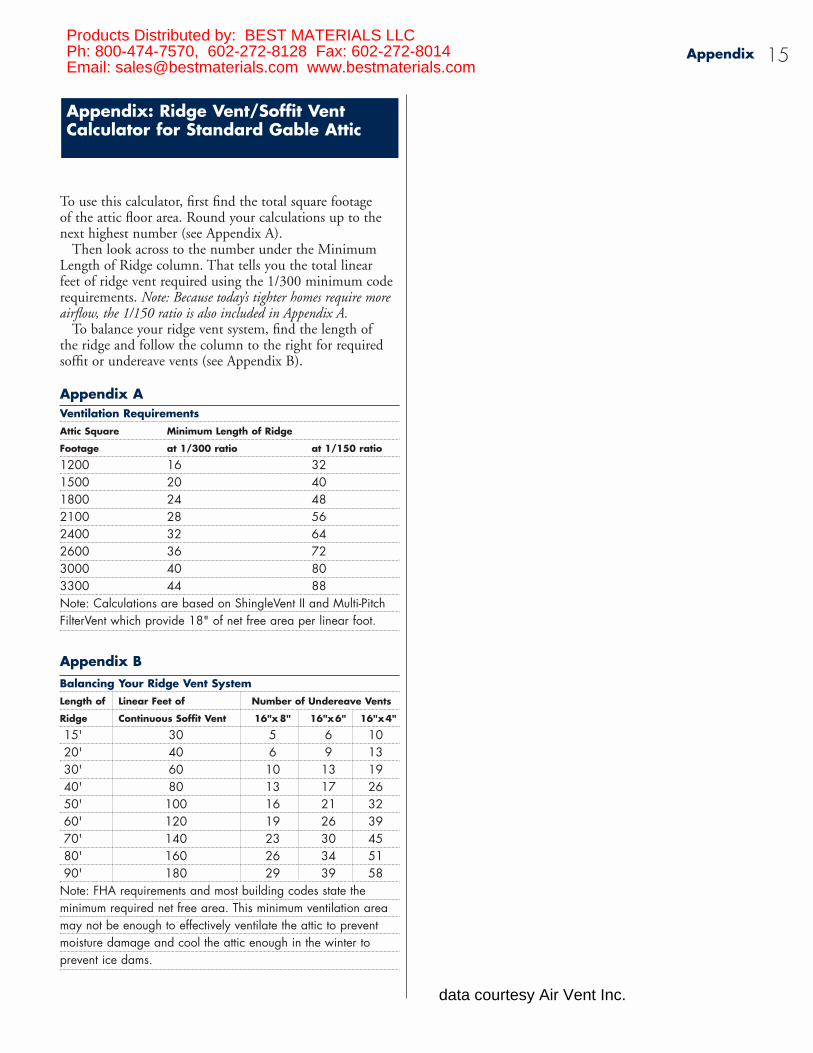
To use this calculator, first find the total square footage of the attic floor area. Round your calculations up to thenext highest number (see Appendix A).
Then look across to the number under the MinimumLength of Ridge column. That tells you the total linear feet of ridge vent required using the 1/300 minimum coderequirements. Note: Because today’s tighter homes require moreairflow, the 1/150 ratio is also included in Appendix A.
To balance your ridge vent system, find the length of the ridge and follow the column to the right for requiredsoffit or undereave vents (see Appendix B).
Appendix AVentilation RequirementsAttic Square Minimum Length of Ridge
Footage at 1/300 ratio at 1/150 ratio
1200 16 321500 20 401800 24 482100 28 562400 32 642600 36 723000 40 803300 44 88Note: Calculations are based on ShingleVent II and Multi-PitchFilterVent which provide 18" of net free area per linear foot.
Appendix BBalancing Your Ridge Vent SystemLength of Linear Feet of Number of Undereave Vents
Ridge Continuous Soffit Vent 16"x 8" 16"x6" 16"x4"
15' 30 5 6 1020' 40 6 9 1330' 60 10 13 1940' 80 13 17 2650' 100 16 21 3260' 120 19 26 3970' 140 23 30 4580' 160 26 34 5190' 180 29 39 58
Note: FHA requirements and most building codes state the minimum required net free area. This minimum ventilation area may not be enough to effectively ventilate the attic to prevent moisture damage and cool the attic enough in the winter to prevent ice dams.
Appendix: Ridge Vent/Soffit VentCalculator for Standard Gable Attic
15Products Distributed by: BEST MATERIALS LLCPh: 800-474-7570, 602-272-8128 Fax: 602-272-8014Email: [email protected] www.bestmaterials.com
data courtesy Air Vent Inc.
to create a flow of air. In addition, this standard assumes a proper balance of exhaust and intake venting. Unfor-tunately, it’s probably safer to assume that assumptionrarely holds true.
If you want to install an effective, year-round ven-tilation system follow the steps below which are based onthe 1/150 ratio. This ratio takes into account that today’shomes are built with – or remodeled with – materials(doors, insulation, windows, etc.) that are more energy efficient. Consequently, these homes are more airtight and need more attic ventilation.
Calculating requirements for an efficient static vent systemThe math involved in calculating ventilation requirementsis simple. A pad and pencil are all you need.
Note: The following process is used to calculate requirementsfor non-powered ventilation systems. If you plan to install apower fan, see calculation instructions on page 14.
1. Determine the square footage of attic area to be ventilated.
To do that, just multiply the length of the attic (in feet) by its width.Example: For this and the following calculations, we’ll assume the home has a 40' by 25' attic area.
Calculation: 40' x 25' = 1,000 square feet of attic area
2. Determine the total net free area required.
Once attic square footage is known, divide by 150 (for the 1/150 ratio). That determines the total amountof net free area needed to properly ventilate the attic.
Calculation:1,000 sq. ft. ÷ 150 = 6.6 square feet of total net free area
3. Determine the amount of intake and exhaust(low and high) net free area required.
For optimum performance, the attic ventilation systemmust be balanced with intake and exhaust vents.
This is a simple calculation: just divide the answer from Step 2 by 2.
Calculation: 6.6 ÷ 2 = 3.3 sq. ft. of intake net free area and 3.3 sq. ft.of exhaust net free area
Section 3: Determining Ventilation Requirements 13
Before the mid-1970s, few people thought about establish-ing precise requirements for attic ventilation. Homesweren’t built as airtight as they are today. If a home had anyattic ventilation at all, it usually consisted of some under-eave vents. In some warmer areas of the country, one ormore louvers might supplement those vents (the purposebeing, as already mentioned, “to catch the breeze”). In especially warm regions, an attic fan might be installed(even though there might not be sufficient intake ventingto assure proper functioning).
Even if designers and specifiers had wanted to calculatespecific requirements for temperature or moisture reduction, they had little research-based information toguide them.
The Federal Housing Administration tried to close thatinformation gap with minimum property standards forbuildings with one or two living units. Since then, otherstandards have been developed. An example of currentminimum requirements for ventilation comes from the2003 International Residential Code (IRC) Section R806:
R806.1 Ventilation required. Enclosed attics and enclosed rafter spaces formed where ceilings are applied directlyto the underside of roof rafters shall have cross ventilation foreach separate space by ventilating openings protected againstthe entrance of rain or snow... R806.2 Minimum area. The total net free ventilating area shallnot be less than 1 to 150 of the area of the space ventilatedexcept that the total area is permitted to be reduced to 1 to 300, provided at least 50 percent and not more than 80 percent of the required ventilating area is provided by ventilators located in the upper portion of the space to be ventilated at least 3 feet (914 mm) above eave or cornice ventswith the balance of the required ventilation provided by eave orcornice vents. As an alternative, the net free cross-ventilation areamay be reduced to 1 to 300 when a vapor barrier having a transmission rate not exceeding 1 perm (57.4 mg/s · m2 · Pa) is installed on the warm side of the ceiling.R806.3 Vent clearance. Where eave or cornice vents are installed, insulation shall not block the free flow of air. A minimum of a 1-inch (25.4 mm) space shall be providedbetween the insulation and the roof sheathing at the location of the vent.
Is adequate attic ventilation now assured by followingthis requirement?
The intent of the requirement, after all, is to establishminimum standards. For example, the IRC permits the netfree area requirement to be reduced to the 1/300 ratio incertain situations. That amounts to less than 1/2" of ventarea for each square foot of attic floor area, barely enough
Section 3: Determining Ventilation Requirements
R806.1 Ventilation required. Enclosed attics and enclosed rafter spaces formed where ceilings are applied directlyto the underside of roof rafters shall have cross ventilation foreach separate space by ventilating openings protected againstthe entrance of rain or snow... R806.2 Minimum area. The total net free ventilating areashall not be less than 1 to 150 of the area of the space ventilatedexcept that the total area is permitted to be reduced to 1 to 300, provided at least 50 percent and not more than 80 percent of the required ventilating area is provided by ventilators located in the upper portion of the space to be ventilated at least 3 feet (914 mm) above eave or cornice ventswith the balance of the required ventilation provided by eave orcornice vents. As an alternative, the net free cross-ventilation areamay be reduced to 1 to 300 when a vapor barrier having a transmission rate not exceeding 1 perm (57.4 mg/s · m2 · Pa) is installed on the warm side of the ceiling.R806.3 Vent clearance. Where eave or cornice vents are installed, insulation shall not block the free flow of air. A minimum of a 1-inch (25.4 mm) space shall be providedbetween the insulation and the roof sheathing at the location of the vent.
Note: For roofs with a 7/12 to 10/12 roof pitch, you maywant to add 20 percent more CFM; and for roofs 11/12 pitchand higher add 30% more CFM to handle the larger volumeof attic space.
2. Determine the amount of intake ventingrequired. The formula is:
CFM rating of fan ÷ 300 = square feet of intake ventilation needed.
Calculation:700 ÷ 300 = 2.3 square feet
To turn that figure into square inches multiply by 144.
Calculation:2.3 x 144 = 331 square inches of net free intake area
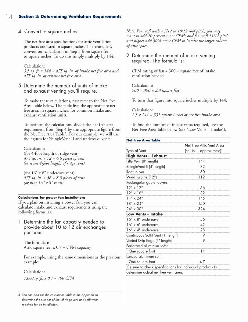
To find the number of intake vents required, use theNet Free Area Table below (see “Low Vents – Intake”).
Net Free Area TableNet Free Attic Vent Area
Type of Vent (sq. in. – approximate)†
High Vents – ExhaustFilterVent (8' length) 144ShingleVent II (4' length) 72Roof louver 50Wind turbine (12") 112Rectangular gable louvers12" x 12" 5612" x 18" 8214" x 24" 14518" x 24" 15024" x 30" 324Low Vents – Intake16" x 8" undereave 5616" x 6" undereave 4216" x 4" undereave 28Continuous Soffit Vent (1' length) 9Vented Drip Edge (1' length) 9Perforated aluminum soffit†
One square foot 14Lanced aluminum soffit†
One square foot 4-7†Be sure to check specifications for individual products to determine actual net free vent area.
Section 3: Determining Ventilation Requirements14
4. Convert to square inches.
The net free area specifications for attic ventilationproducts are listed in square inches. Therefore, let’s convert our calculation in Step 3 from square feet to square inches. To do this simply multiply by 144.
Calculation: 3.3 sq. ft. x 144 = 475 sq. in. of intake net free area and475 sq. in. of exhaust net free area.
5. Determine the number of units of intake and exhaust venting you’ll require.
To make these calculations, first refer to the Net FreeArea Table below. The table lists the approximate netfree area, in square inches, for common intake andexhaust ventilation units.
To perform the calculations, divide the net free arearequirement from Step 4 by the appropriate figure fromthe Net Free Area Table3. For our example, we will usethe figures for ShingleVent II and undereave vents.
Calculation:(for 4-foot length of ridge vent)475 sq. in. ÷ 72 = 6.6 pieces of vent (or seven 4-foot lengths of ridge vent)
(for 16" x 8" undereave vent)475 sq. in. ÷ 56 = 8.5 pieces of vent (or nine 16" x 8" vents)
Calculations for power fan installationsIf you plan on installing a power fan, you can calculate intake and exhaust requirements using the following formulas:
1. Determine the fan capacity needed to provide about 10 to 12 air exchanges per hour.
The formula is:Attic square feet x 0.7 = CFM capacity
For example, using the same dimensions as the previousexample:
Calculation:
1,000 sq. ft. x 0.7 = 700 CFM
3 You can also use the calculation table in the Appendix to determine the number of feet of ridge vent and soffit vent required for an installation.
Introduction: The Year-Round Benefits of Proper Attic Ventilation
What’s the purpose of attic ventilation? It seems like asimple question, easy enough to answer. Unfortunately, all too often, that’s not the case. Most homeowners – and even some experienced builders and contractors –believe the purpose of attic ventilation is to remove heatthat builds up in the summer.
That’s accurate, of course. But what that answer leavesout is just as important as what it includes.
If you understand the principles of attic ventilation, you know an effective venting system provides year-round benefits.
• During warmer months, ventilation helps keep attics cool.
• During colder months, ventilation reduces moisture to help keep attics dry. It also helps prevent ice dams.
We can make that answer more specific – and more meaningful – by translating those functional descriptionsinto a list of benefits:
Several purposes of an attic ventilation system are to provide added comfort, to help protect against damage to materials and structure, and to help reduce energy consumption – during all four seasons of the year.
Your goal should be to provide those benefits wheneveryou design and install an attic ventilation system. The rest of this booklet will show you how.
Ventilation During Warm WeatherDealing with the effects of heat. Why, on a hot day, are the upper rooms of a home always warmer?
Part of the answer, of course, is simple physics: hot(lighter) air rises while cooler (denser) air falls. But in most homes – the vast majority of homes without adequateattic ventilation – a far more important factor comes intoplay: the downward migration of heat.
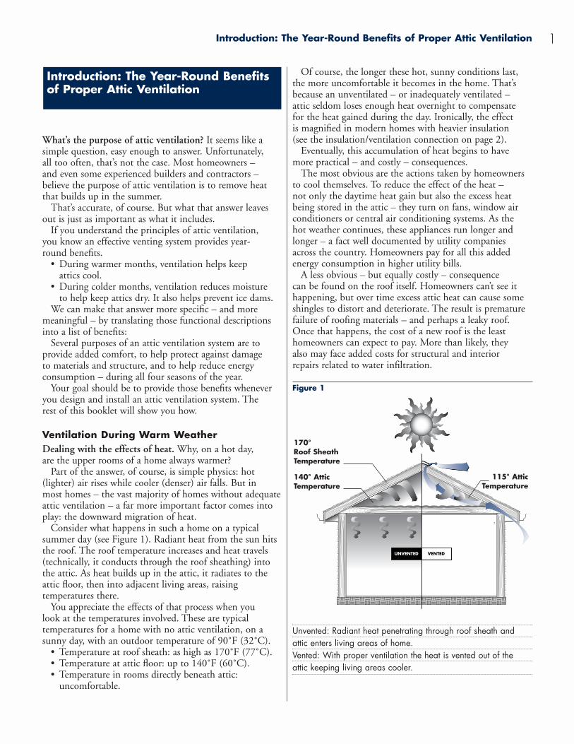
Consider what happens in such a home on a typical summer day (see Figure 1). Radiant heat from the sun hitsthe roof. The roof temperature increases and heat travels(technically, it conducts through the roof sheathing) intothe attic. As heat builds up in the attic, it radiates to theattic floor, then into adjacent living areas, raising temperatures there.
You appreciate the effects of that process when you look at the temperatures involved. These are typical temperatures for a home with no attic ventilation, on asunny day, with an outdoor temperature of 90˚F (32˚C).
• Temperature at roof sheath: as high as 170˚F (77˚C).• Temperature at attic floor: up to 140˚F (60˚C).• Temperature in rooms directly beneath attic:
uncomfortable.
Introduction: The Year-Round Benefits of Proper Attic Ventilation
Of course, the longer these hot, sunny conditions last,the more uncomfortable it becomes in the home. That’sbecause an unventilated – or inadequately ventilated – attic seldom loses enough heat overnight to compensate for the heat gained during the day. Ironically, the effect is magnified in modern homes with heavier insulation (see the insulation/ventilation connection on page 2).
Eventually, this accumulation of heat begins to havemore practical – and costly – consequences.
The most obvious are the actions taken by homeownersto cool themselves. To reduce the effect of the heat – not only the daytime heat gain but also the excess heatbeing stored in the attic – they turn on fans, window airconditioners or central air conditioning systems. As the hot weather continues, these appliances run longer andlonger – a fact well documented by utility companies across the country. Homeowners pay for all this addedenergy consumption in higher utility bills.
A less obvious – but equally costly – consequence can be found on the roof itself. Homeowners can’t see ithappening, but over time excess attic heat can cause some shingles to distort and deteriorate. The result is prematurefailure of roofing materials – and perhaps a leaky roof.Once that happens, the cost of a new roof is the leasthomeowners can expect to pay. More than likely, they also may face added costs for structural and interior repairs related to water infiltration.
Figure 1
Unvented: Radiant heat penetrating through roof sheath andattic enters living areas of home.Vented: With proper ventilation the heat is vented out of the attic keeping living areas cooler.
170°Roof Sheath Temperature
140° Attic Temperature
115° AtticTemperature
1
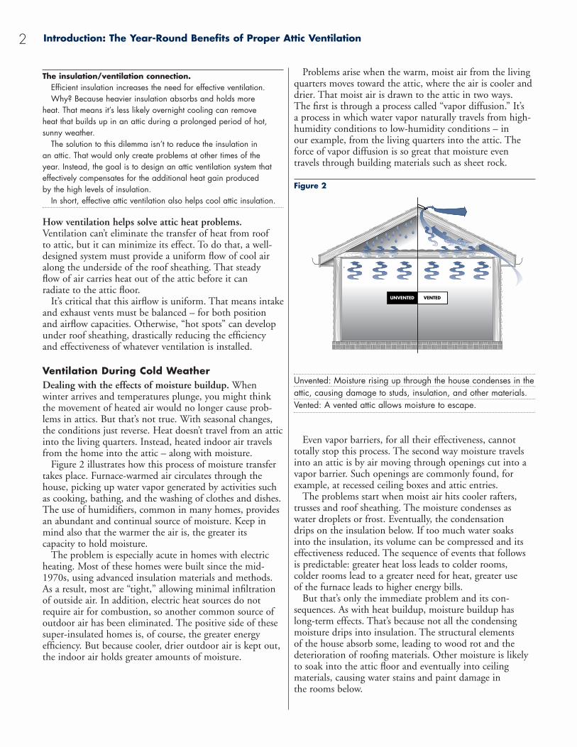
Problems arise when the warm, moist air from the livingquarters moves toward the attic, where the air is cooler anddrier. That moist air is drawn to the attic in two ways. The first is through a process called “vapor diffusion.” It’s a process in which water vapor naturally travels from high-humidity conditions to low-humidity conditions – in our example, from the living quarters into the attic. Theforce of vapor diffusion is so great that moisture even travels through building materials such as sheet rock.
Figure 2
Unvented: Moisture rising up through the house condenses in theattic, causing damage to studs, insulation, and other materials.Vented: A vented attic allows moisture to escape.
Even vapor barriers, for all their effectiveness, cannot totally stop this process. The second way moisture travelsinto an attic is by air moving through openings cut into avapor barrier. Such openings are commonly found, forexample, at recessed ceiling boxes and attic entries.
The problems start when moist air hits cooler rafters,trusses and roof sheathing. The moisture condenses aswater droplets or frost. Eventually, the condensation drips on the insulation below. If too much water soaks into the insulation, its volume can be compressed and itseffectiveness reduced. The sequence of events that follows is predictable: greater heat loss leads to colder rooms, colder rooms lead to a greater need for heat, greater use of the furnace leads to higher energy bills.
But that’s only the immediate problem and its con-sequences. As with heat buildup, moisture buildup haslong-term effects. That’s because not all the condensingmoisture drips into insulation. The structural elements of the house absorb some, leading to wood rot and thedeterioration of roofing materials. Other moisture is likelyto soak into the attic floor and eventually into ceiling materials, causing water stains and paint damage in the rooms below.
2
The insulation/ventilation connection.Efficient insulation increases the need for effective ventilation. Why? Because heavier insulation absorbs and holds more
heat. That means it’s less likely overnight cooling can remove heat that builds up in an attic during a prolonged period of hot, sunny weather.
The solution to this dilemma isn’t to reduce the insulation in an attic. That would only create problems at other times of the year. Instead, the goal is to design an attic ventilation system thateffectively compensates for the additional heat gain produced by the high levels of insulation.
In short, effective attic ventilation also helps cool attic insulation.
How ventilation helps solve attic heat problems.Ventilation can’t eliminate the transfer of heat from roof to attic, but it can minimize its effect. To do that, a well-designed system must provide a uniform flow of cool airalong the underside of the roof sheathing. That steady flow of air carries heat out of the attic before it can radiate to the attic floor.
It’s critical that this airflow is uniform. That means intakeand exhaust vents must be balanced – for both positionand airflow capacities. Otherwise, “hot spots” can developunder roof sheathing, drastically reducing the efficiency and effectiveness of whatever ventilation is installed.
Ventilation During Cold WeatherDealing with the effects of moisture buildup. When winter arrives and temperatures plunge, you might thinkthe movement of heated air would no longer cause prob-lems in attics. But that’s not true. With seasonal changes,the conditions just reverse. Heat doesn’t travel from an atticinto the living quarters. Instead, heated indoor air travelsfrom the home into the attic – along with moisture.
Figure 2 illustrates how this process of moisture transfertakes place. Furnace-warmed air circulates through thehouse, picking up water vapor generated by activities suchas cooking, bathing, and the washing of clothes and dishes.The use of humidifiers, common in many homes, providesan abundant and continual source of moisture. Keep inmind also that the warmer the air is, the greater its capacity to hold moisture.
The problem is especially acute in homes with electricheating. Most of these homes were built since the mid-1970s, using advanced insulation materials and methods.As a result, most are “tight,” allowing minimal infiltrationof outside air. In addition, electric heat sources do notrequire air for combustion, so another common source ofoutdoor air has been eliminated. The positive side of thesesuper-insulated homes is, of course, the greater energy efficiency. But because cooler, drier outdoor air is kept out,the indoor air holds greater amounts of moisture.
Introduction: The Year-Round Benefits of Proper Attic Ventilation
Introduction: The Year-Round Benefits of Proper Attic Ventilation 3
How ventilation helps solve attic moisture problems.Although the problems of attic heat and moisture have different causes, they share a common solution: a high-efficiency ventilation system that allows a uniform flow of air to sweep the underside of the roof sheathing. Inwarmer months, such a system exhausts hot air from anattic; in the colder months, it exchanges warm, moist airwith cooler, drier air. In both cases, the result is the same: less damage to a home.
Dealing with the effects of ice dams. Winter creates a special attic ventilation problem in areas where snowfalland cold temperatures are common occurrences. The problem begins with the formation of ice dams – literallybarriers formed of ice – that prevent melt water from running off a roof. (The map in Figure 3 shows areas of the U.S. where average winter conditions can lead to the formation of ice dams.)
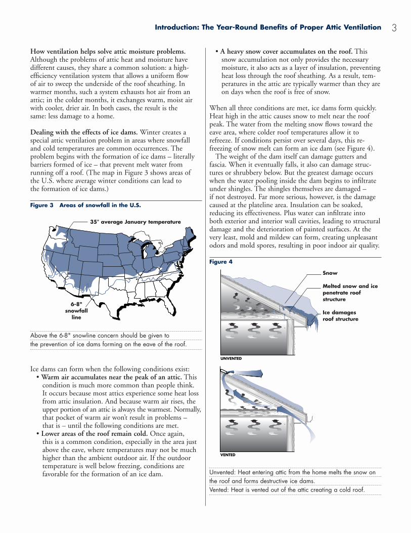
Figure 3 Areas of snowfall in the U.S.
Above the 6-8" snowline concern should be given to the prevention of ice dams forming on the eave of the roof.
Ice dams can form when the following conditions exist:• Warm air accumulates near the peak of an attic. This
condition is much more common than people think. It occurs because most attics experience some heat lossfrom attic insulation. And because warm air rises, theupper portion of an attic is always the warmest. Normally,that pocket of warm air won’t result in problems – that is – until the following conditions are met.
• Lower areas of the roof remain cold. Once again, this is a common condition, especially in the area justabove the eave, where temperatures may not be muchhigher than the ambient outdoor air. If the outdoortemperature is well below freezing, conditions arefavorable for the formation of an ice dam.
• A heavy snow cover accumulates on the roof. Thissnow accumulation not only provides the necessarymoisture, it also acts as a layer of insulation, preventingheat loss through the roof sheathing. As a result, tem-peratures in the attic are typically warmer than they areon days when the roof is free of snow.
When all three conditions are met, ice dams form quickly.Heat high in the attic causes snow to melt near the roofpeak. The water from the melting snow flows toward theeave area, where colder roof temperatures allow it torefreeze. If conditions persist over several days, this re-freezing of snow melt can form an ice dam (see Figure 4).
The weight of the dam itself can damage gutters and fascia. When it eventually falls, it also can damage struc-tures or shrubbery below. But the greatest damage occurswhen the water pooling inside the dam begins to infiltrateunder shingles. The shingles themselves are damaged – if not destroyed. Far more serious, however, is the damagecaused at the plateline area. Insulation can be soaked,reducing its effectiveness. Plus water can infiltrate into both exterior and interior wall cavities, leading to structuraldamage and the deterioration of painted surfaces. At thevery least, mold and mildew can form, creating unpleasantodors and mold spores, resulting in poor indoor air quality.
Figure 4
Unvented: Heat entering attic from the home melts the snow onthe roof and forms destructive ice dams.Vented: Heat is vented out of the attic creating a cold roof.
35° average January temperature
6-8" snowfall
line
Snow
Melted snow and icepenetrate roof structure
Ice damages roof structure
A defense against ice damsTo reduce the possibility of ice dams, use a three-step approach:1. Install adequate attic ventilation. Because ice dams
form when a roof has warm upper surfaces and cold lower surfaces,the solution is to equalize temperatures over the entire roof. Themost effective way to equalize temperatures is to create a cold roof.
To do that, you need a well designed attic ventilation system that will supply airflow along the entire underside of the roof deck. That’s critical, because only a uniformly distributed airflow canreduce variation in roof temperatures from peak to eave.
One of the most efficient and effective systems (from both cost and performance standpoints) uses ridge vents and an evenly distributed layout of soffit vents.
2. Install adequate attic insulation. Attic insulation serves two purposes. First, it reduces heat loss from a home’s living quarters. Since that heat loss is a key factor contributing to the creation of ice dams, stopping it at its source is critical. Second,adequate attic insulation diminishes the energy impact of havingcold air flowing through the attic.
When installing insulation – or checking existing insulation – be sure to install adequate amounts around electrical fixtures andwiring and plumbing chases. These areas often contribute to significant heat loss. With existing insulation, also check for water damage and for areas compressed by foot traffic or storedobjects. Finally, make certain existing insulation meets today’s R-Value requirements.
3. If possible, install waterproofing shingle underlayment (WSU). Even the most efficient attic ventilation system may not be enough to eliminate all ice dams. A combinationof weather conditions, roof pitch, building orientation and other factors may allow ice dams to form under certain conditions. If thathappens, a WSU barrier can minimize – and possibly eliminate –water infiltration into the building structure (see Figure 7).
Install WSU according to the manufacturer’s instructions. In general, install WSU at least two feet above the interior wall line;many contractors say a three-foot barrier is even better. When working in valleys, install WSU three feet on each side of the valley center (see Figure 8).
1 It’s difficult to say precisely how much insulation will be required. Manyfactors, from house design to its orientation to the weather, enter into theequation. A good rule of thumb, however, is to provide at least 10 to 12inches of insulation. That’s equivalent to an R-Value of 38.
Introduction: The Year-Round Benefits of Proper Attic Ventilation4
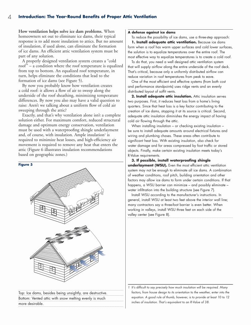
How ventilation helps solve ice dam problems. Whenhomeowners set out to eliminate ice dams, their typicalresponse is to add more insulation to attics. But no amountof insulation, if used alone, can eliminate the formation of ice dams. An efficient attic ventilation system must bepart of any solution.
A properly designed ventilation system creates a “coldroof” – a condition where the roof temperature is equalizedfrom top to bottom. An equalized roof temperature, inturn, helps eliminate the conditions that lead to the formation of ice dams (see Figure 5).
By now you probably know how ventilation creates a cold roof: it allows a flow of air to sweep along the underside of the roof sheathing, minimizing temperaturedifferences. By now you also may have a valid question toraise: Aren’t we talking about a uniform flow of cold airsweeping through the attic?
Exactly, and that’s why ventilation alone isn’t a completesolution either. For maximum comfort, reduced structuraldamage and optimum energy conservation, ventilationmust be used with a waterproofing shingle underlaymentand, of course, with insulation. Ample insulation1 isrequired to minimize heat losses, and high-efficiency airmovement is required to remove any heat that enters theattic (Figure 6 illustrates insulation recommendations based on geographic zones.)
Figure 5
Top: Ice dams, besides being unsightly, are destructive.Bottom: Vented attic with snow melting evenly is much more desirable.
Section 1: How Ventilation Works 5
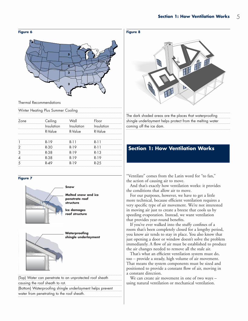
Figure 6
Winter Heating Plus Summer Cooling
Zone Ceiling Wall FloorInsulation Insulation InsulationR-Value R-Value R-Value
1 R-19 R-11 R-112 R-30 R-19 R-113 R-38 R-19 R-134 R-38 R-19 R-195 R-49 R-19 R-25
Figure 7
(Top) Water can penetrate to an unprotected roof sheath causing the roof sheath to rot.(Bottom) Waterproofing shingle underlayment helps prevent water from penetrating to the roof sheath.
1
Figure 8
The dark shaded areas are the places that waterproofing shingle underlayment helps protect from the melting water coming off the ice dam.
“Ventilate” comes from the Latin word for “to fan,”the action of causing air to move.
And that’s exactly how ventilation works: it provides the conditions that allow air to move.
For our purposes, however, we have to get a little more technical, because efficient ventilation requires a very specific type of air movement. We’re not interested in moving air just to create a breeze that cools us by speeding evaporation. Instead, we want ventilation that provides year-round benefits.
If you’ve ever walked into the stuffy confines of a room that’s been completely closed for a lengthy period,you know air tends to stay in place. You also know that just opening a door or window doesn’t solve the problemimmediately. A flow of air must be established to producethe air changes needed to remove all the stale air.
That’s what an efficient ventilation system must do, too – provide a steady, high volume of air movement. That means the system components must be sized and positioned to provide a constant flow of air, moving in a constant direction.
We can create air movement in one of two ways – using natural ventilation or mechanical ventilation.
Section 1: How Ventilation Works
Thermal Recommendations
Snow
Melted snow and ice penetrate roof structure
Ice damages roof structure
Waterproofingshingle underlayment
Section 1: How Ventilation Works6
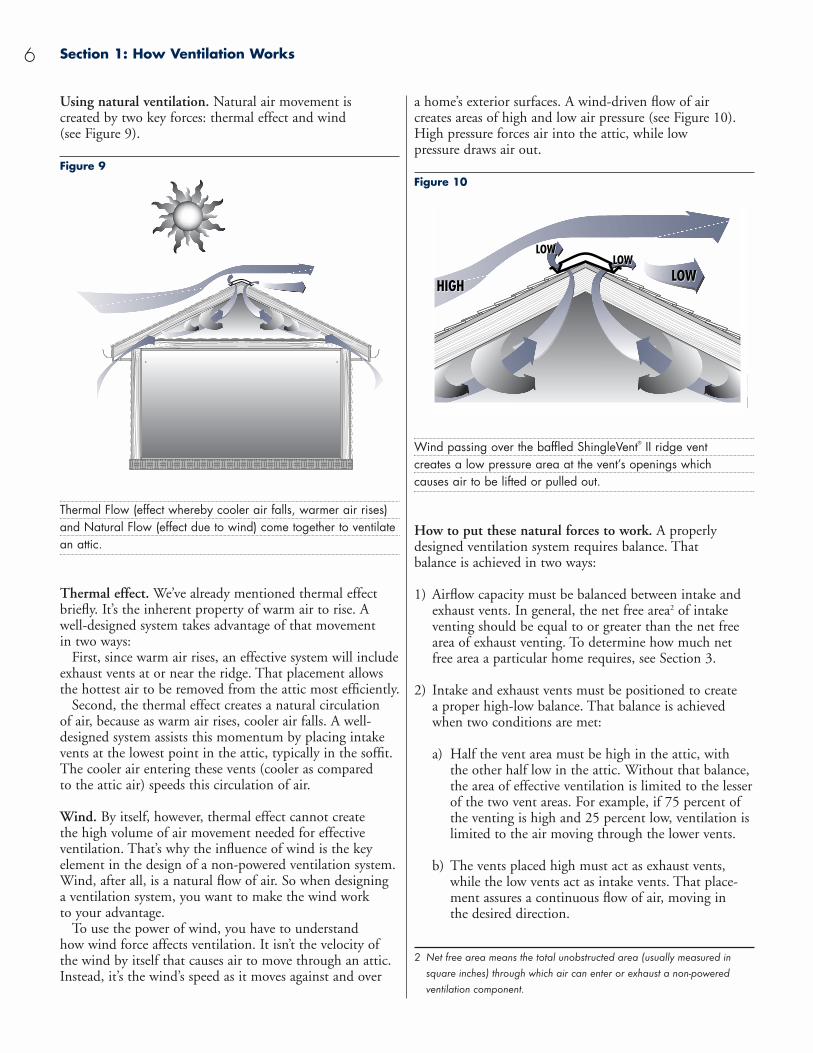
Using natural ventilation. Natural air movement is created by two key forces: thermal effect and wind (see Figure 9).
Figure 9
Thermal Flow (effect whereby cooler air falls, warmer air rises) and Natural Flow (effect due to wind) come together to ventilatean attic.
Thermal effect. We’ve already mentioned thermal effectbriefly. It’s the inherent property of warm air to rise. Awell-designed system takes advantage of that movement in two ways:
First, since warm air rises, an effective system will includeexhaust vents at or near the ridge. That placement allowsthe hottest air to be removed from the attic most efficiently.
Second, the thermal effect creates a natural circulation of air, because as warm air rises, cooler air falls. A well-designed system assists this momentum by placing intakevents at the lowest point in the attic, typically in the soffit.The cooler air entering these vents (cooler as compared to the attic air) speeds this circulation of air.
Wind. By itself, however, thermal effect cannot create the high volume of air movement needed for effective ventilation. That’s why the influence of wind is the key element in the design of a non-powered ventilation system.Wind, after all, is a natural flow of air. So when designing a ventilation system, you want to make the wind work to your advantage.
To use the power of wind, you have to understand how wind force affects ventilation. It isn’t the velocity ofthe wind by itself that causes air to move through an attic.Instead, it’s the wind’s speed as it moves against and over
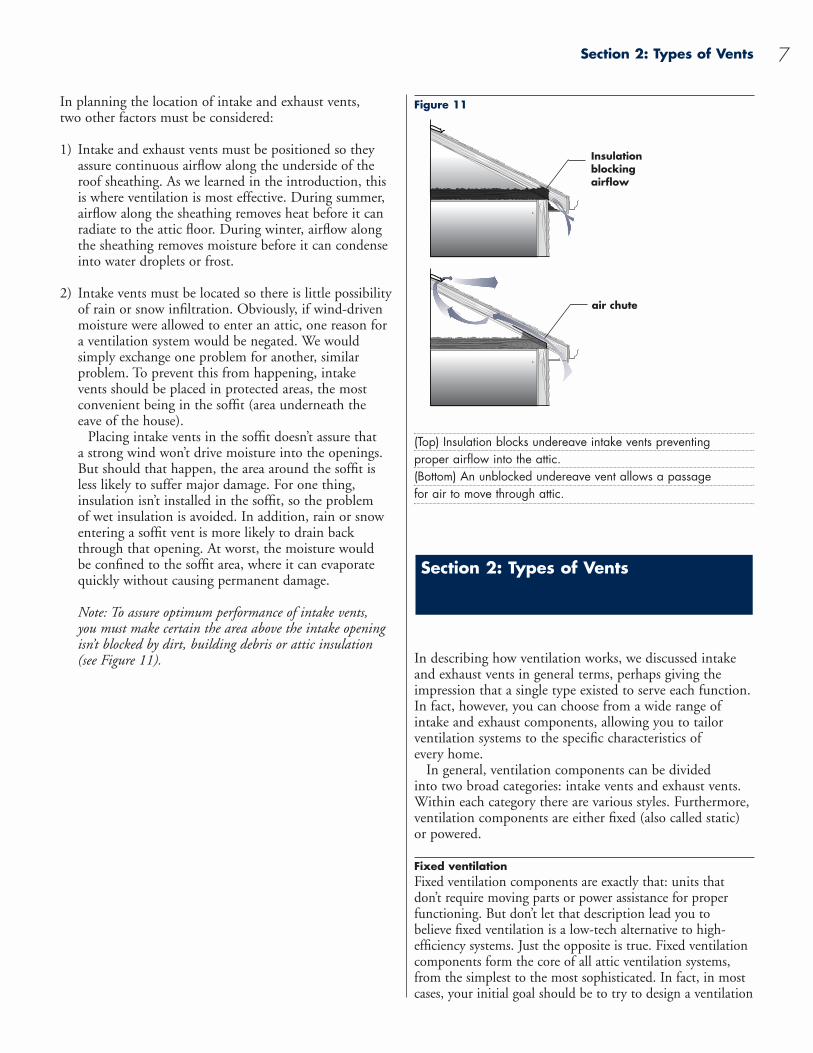
a home’s exterior surfaces. A wind-driven flow of air creates areas of high and low air pressure (see Figure 10).High pressure forces air into the attic, while low pressure draws air out.
Figure 10
Wind passing over the baffled ShingleVent® II ridge vent creates a low pressure area at the vent’s openings which causes air to be lifted or pulled out.
How to put these natural forces to work. A properlydesigned ventilation system requires balance. That balance is achieved in two ways:
1) Airflow capacity must be balanced between intake andexhaust vents. In general, the net free area2 of intakeventing should be equal to or greater than the net freearea of exhaust venting. To determine how much netfree area a particular home requires, see Section 3.
2) Intake and exhaust vents must be positioned to create a proper high-low balance. That balance is achievedwhen two conditions are met:
a) Half the vent area must be high in the attic, with the other half low in the attic. Without that balance,the area of effective ventilation is limited to the lesserof the two vent areas. For example, if 75 percent ofthe venting is high and 25 percent low, ventilation islimited to the air moving through the lower vents.
b) The vents placed high must act as exhaust vents,while the low vents act as intake vents. That place-ment assures a continuous flow of air, moving in the desired direction.
2 Net free area means the total unobstructed area (usually measured insquare inches) through which air can enter or exhaust a non-poweredventilation component.
Section 2: Types of Vents 7
In planning the location of intake and exhaust vents, two other factors must be considered:
1) Intake and exhaust vents must be positioned so theyassure continuous airflow along the underside of theroof sheathing. As we learned in the introduction, this is where ventilation is most effective. During summer,airflow along the sheathing removes heat before it canradiate to the attic floor. During winter, airflow alongthe sheathing removes moisture before it can condenseinto water droplets or frost.
2) Intake vents must be located so there is little possibilityof rain or snow infiltration. Obviously, if wind-drivenmoisture were allowed to enter an attic, one reason for a ventilation system would be negated. We would simply exchange one problem for another, similar problem. To prevent this from happening, intake vents should be placed in protected areas, the most convenient being in the soffit (area underneath the eave of the house).
Placing intake vents in the soffit doesn’t assure that a strong wind won’t drive moisture into the openings. But should that happen, the area around the soffit is less likely to suffer major damage. For one thing, insulation isn’t installed in the soffit, so the problem of wet insulation is avoided. In addition, rain or snowentering a soffit vent is more likely to drain backthrough that opening. At worst, the moisture would be confined to the soffit area, where it can evaporatequickly without causing permanent damage.
Note: To assure optimum performance of intake vents, you must make certain the area above the intake opening isn’t blocked by dirt, building debris or attic insulation(see Figure 11).
Figure 11
(Top) Insulation blocks undereave intake vents preventing proper airflow into the attic.(Bottom) An unblocked undereave vent allows a passage for air to move through attic.
In describing how ventilation works, we discussed intakeand exhaust vents in general terms, perhaps giving theimpression that a single type existed to serve each function.In fact, however, you can choose from a wide range ofintake and exhaust components, allowing you to tailor ventilation systems to the specific characteristics of every home.
In general, ventilation components can be divided into two broad categories: intake vents and exhaust vents.Within each category there are various styles. Furthermore,ventilation components are either fixed (also called static)or powered.
Fixed ventilationFixed ventilation components are exactly that: units thatdon’t require moving parts or power assistance for properfunctioning. But don’t let that description lead you to believe fixed ventilation is a low-tech alternative to high-efficiency systems. Just the opposite is true. Fixed ventilation components form the core of all attic ventilation systems,from the simplest to the most sophisticated. In fact, in mostcases, your initial goal should be to try to design a ventilation
Section 2: Types of Vents
Insulationblockingairflow
air chute
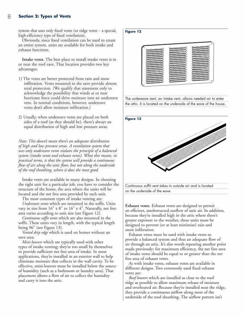
Figure 12
The undereave vent, an intake vent, allows needed air to enter the attic. It is located on the underside of the eave of the house.
Figure 13
Continuous soffit vent takes in outside air and is located on the underside of the eave.
Exhaust vents. Exhaust vents are designed to permit an efficient, unobstructed outflow of attic air. In addition,because they’re installed high in the attic where there’sgreater exposure to the weather, these units must bedesigned to prevent (or at least minimize) rain and snow infiltration.
Exhaust vents must be used with intake vents to provide a balanced system and thus an adequate flow of air through an attic. It’s also worth repeating another pointmade previously: for maximum efficiency, the net free areaof intake vents should be equal to or greater than the net free area of exhaust vents.
As with intake vents, exhaust vents are available in different designs. Two commonly used fixed exhaust vents are:
Roof louvers which are installed as close to the roof ridge as possible to allow maximum release of moisture and overheated air. Because they’re installed near the ridge,they provide a continuous airflow along most of the underside of the roof sheathing. The airflow pattern isn’t
Section 2: Types of Vents8
system that uses only fixed vents (or ridge vents – a special,high-efficiency type of fixed ventilation).
Obviously, since fixed ventilation can be used to create an entire system, units are available for both intake andexhaust functions.
Intake vents. The best place to install intake vents is in or near the roof eave. That location provides two keyadvantages:
1) The vents are better protected from rain and snow infiltration. Vents mounted in the eave provide almosttotal protection. (We qualify that statement only toacknowledge the possibility that winds at or near hurricane force could drive moisture into an undereavevent. In normal conditions, however, undereave vents don’t allow moisture infiltration.)
2) Usually, when undereave vents are placed on both sides of a roof (as they should be), there’s always anequal distribution of high and low pressure areas.
Note: This doesn’t mean there’s an adequate distribution of high and low pressure areas. A ventilation system that uses only undereave vents violates the principle of a balancedsystem (intake vents and exhaust vents). What this means, inpractical terms, is that the system will provide a continuousflow of air along the attic floor, but not along the underside of the roof sheathing, where it does the most good.
Intake vents are available in many designs. In choosingthe right unit for a particular job, you have to consider thestructure of the home, the area where the units will belocated and the net free area provided by each unit.
The most common types of intake venting are:Undereave vents which are mounted in the soffit. Units
vary in size from 16" x 8" to 16" x 4". Naturally, net freearea varies according to unit size (see Figure 12).
Continuous soffit vents which are also mounted in the soffit. These units vary in length, with the typical length being 96" (see Figure 13).
Vented drip edge which is used on homes without an eave area.
Mini-louvers which are typically used with other types of intake venting; they’re too small by themselves to provide sufficient net free area of intake. In most applications, they’re installed in an exterior wall to helpeliminate moisture that collects in the wall cavity. To beeffective, mini-louvers must be installed below the source of humidity (such as a bathroom or laundry area). Thatplacement allows a flow of air to collect the humidity and carry it into the attic.

Section 2: Types of Vents 9
uniform, however, so for maximum effectiveness, ventsshould be spaced equally along the roof (see Figure 14).
Figure 14
A roof louver is an exhaust vent located near the ridge.
Gable louvers which are typically installed in the gables. Twotypes are available: rectangular and triangular. In most instal-lations, a unit is placed at each gable end (see Figure 15).
Figure 15
A gable louver, an exhaust vent, allows unwanted air to flow out of the attic. These are located at the ends of the attic.
Note: Sometimes louvers are installed in opposite gable ends,without intake venting, in the mistaken assumption that agood “cross flow” of air can provide adequate ventilation.What typically happens, however, is illustrated in Figures 16and 17. If wind direction is perpendicular to the ridge, thelouvers act as both intake and exhaust vents, providing vent-ilation only in the areas near the vents. If the wind direction isparallel to the ridge, a cross flow of air is established, althoughthe flow tends to dip toward the attic floor, leaving the hottestair still at the underside of the roof sheathing. Of course, if
absolutely no intake venting can be installed at low points inthe attic, a louver-only installation is preferable to no ventilation at all.
Figure 16
With wind blowing perpendicular to the ridge, the louvers act as both intake and exhaust vents.
Figure 17
With wind blowing parallel to the ridge, airflow dips towards the attic floor leaving the hottest air still on the underside of the roof sheathing.
Ridge ventsAs mentioned above, ridge vents are a special type of fixedexhaust venting. That distinction is warranted, becauseridge vents offer unique advantages when compared toother fixed venting units. Those advantages include:
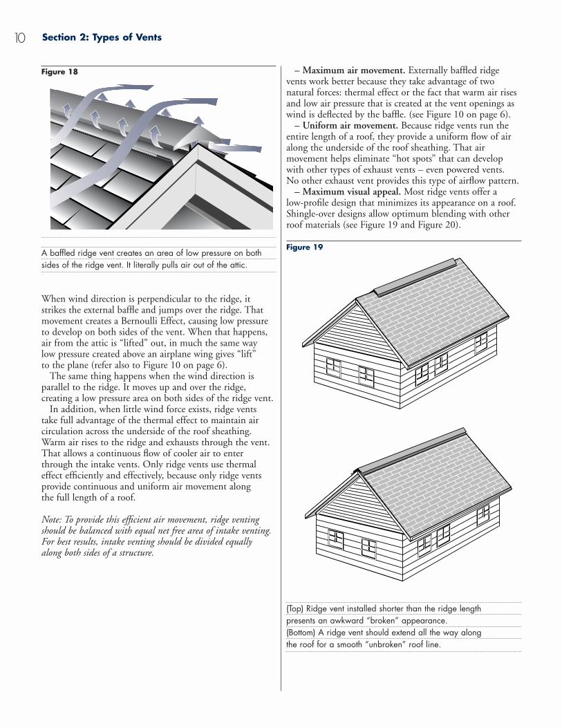
– Maximum efficiency. The best ridge vents use an external baffle designed to draw heated air from an attic regardless of wind direction or force. Figure 18 shows howthat happens.
– Maximum air movement. Externally baffled ridgevents work better because they take advantage of two natural forces: thermal effect or the fact that warm air risesand low air pressure that is created at the vent openings aswind is deflected by the baffle. (see Figure 10 on page 6).
– Uniform air movement. Because ridge vents run theentire length of a roof, they provide a uniform flow of airalong the underside of the roof sheathing. That air movement helps eliminate “hot spots” that can developwith other types of exhaust vents – even powered vents. No other exhaust vent provides this type of airflow pattern.
– Maximum visual appeal. Most ridge vents offer a low-profile design that minimizes its appearance on a roof.Shingle-over designs allow optimum blending with otherroof materials (see Figure 19 and Figure 20).
Figure 19
(Top) Ridge vent installed shorter than the ridge length presents an awkward “broken” appearance.(Bottom) A ridge vent should extend all the way along the roof for a smooth “unbroken” roof line.
Section 2: Types of Vents10
Figure 18
A baffled ridge vent creates an area of low pressure on both sides of the ridge vent. It literally pulls air out of the attic.
When wind direction is perpendicular to the ridge, it strikes the external baffle and jumps over the ridge. Thatmovement creates a Bernoulli effect, causing low pressureto develop on both sides of the vent. When that happens,air from the attic is “lifted” out, in much the same way low pressure created above an airplane wing gives “lift” to the plane (refer also to Figure 10 on page 6).
The same thing happens when the wind direction is parallel to the ridge. It moves up and over the ridge, creating a low pressure area on both sides of the ridge vent.
In addition, when little wind force exists, ridge vents take full advantage of the thermal effect to maintain air circulation across the underside of the roof sheathing.Warm air rises to the ridge and exhausts through the vent.That allows a continuous flow of cooler air to enterthrough the intake vents. Only ridge vents use thermaleffect efficiently and effectively, because only ridge ventsprovide continuous and uniform air movement along the full length of a roof.
Note: To provide this efficient air movement, ridge ventingshould be balanced with equal net free area of intake venting.For best results, intake venting should be divided equally alongboth sides of a structure.
A baffled ridge vent creates an area of low pressure on both sides of the ridge vent. It literally pulls air out of the attic.
When wind direction is perpendicular to the ridge, it strikes the external baffle and jumps over the ridge. Thatmovement creates a Bernoulli Effect, causing low pressureto develop on both sides of the vent. When that happens,air from the attic is “lifted” out, in much the same way low pressure created above an airplane wing gives “lift” to the plane (refer also to Figure 10 on page 6).
The same thing happens when the wind direction is parallel to the ridge. It moves up and over the ridge, creating a low pressure area on both sides of the ridge vent.
In addition, when little wind force exists, ridge vents take full advantage of the thermal effect to maintain air circulation across the underside of the roof sheathing.Warm air rises to the ridge and exhausts through the vent.That allows a continuous flow of cooler air to enterthrough the intake vents. Only ridge vents use thermaleffect efficiently and effectively, because only ridge ventsprovide continuous and uniform air movement along the full length of a roof.
Note: To provide this efficient air movement, ridge ventingshould be balanced with equal net free area of intake venting.For best results, intake venting should be divided equally along both sides of a structure.
Section 2: Types of Vents 11
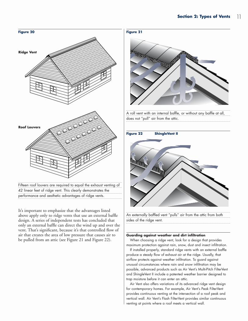
Figure 20
Fifteen roof louvers are required to equal the exhaust venting of 42 linear feet of ridge vent. This clearly demonstrates the performance and aesthetic advantages of ridge vents.
It’s important to emphasize that the advantages listed above apply only to ridge vents that use an external baffledesign. A series of independent tests has concluded thatonly an external baffle can direct the wind up and over thevent. That’s significant, because it’s that controlled flow ofair that creates the area of low pressure that causes air to be pulled from an attic (see Figure 21 and Figure 22).
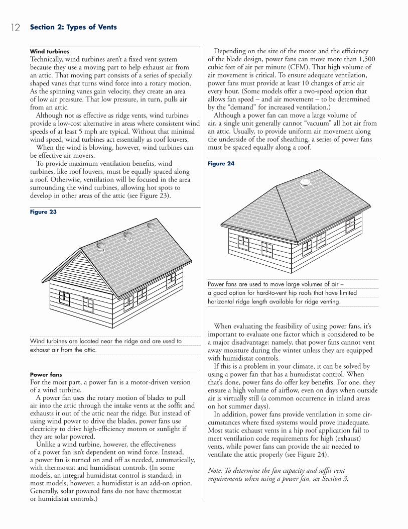
Figure 21
A roll vent with an internal baffle, or without any baffle at all, does not “pull” air from the attic.
Figure 22 ShingleVent II
An externally baffled vent “pulls” air from the attic from both sides of the ridge vent.
Guarding against weather and dirt infiltrationWhen choosing a ridge vent, look for a design that provides
maximum protection against rain, snow, dust and insect infiltration.If installed properly, standard ridge vents with an external baffle
produce a steady flow of exhaust air at the ridge. Usually, that airflow protects against weather infiltration. To guard against unusual circumstances where rain and snow infiltration may be possible, advanced products such as Air Vent’s Multi-Pitch FilterVentand ShingleVent II include a patented weather barrier designed totrap moisture before it can enter an attic.
Air Vent also offers variations of its advanced ridge vent designfor contemporary homes. For example, Air Vent’s Peak FilterVentprovides continuous venting at the intersection of a roof peak andvertical wall. Air Vent’s Flash FilterVent provides similar continuousventing at points where a roof meets a vertical wall.
Ridge Vent
Roof Louvers
Depending on the size of the motor and the efficiency of the blade design, power fans can move more than 1,500cubic feet of air per minute (CFM). That high volume ofair movement is critical. To ensure adequate ventilation,power fans must provide at least 10 changes of attic airevery hour. (Some models offer a two-speed option thatallows fan speed – and air movement – to be determinedby the “demand” for increased ventilation.)
Although a power fan can move a large volume of air, a single unit generally cannot “vacuum” all hot air froman attic. Usually, to provide uniform air movement along the underside of the roof sheathing, a series of power fans must be spaced equally along a roof.
Figure 24
Power fans are used to move large volumes of air – a good option for hard-to-vent hip roofs that have limited horizontal ridge length available for ridge venting.
When evaluating the feasibility of using power fans, it’simportant to evaluate one factor which is considered to bea major disadvantage: namely, that power fans cannot ventaway moisture during the winter unless they are equippedwith humidistat controls.
If this is a problem in your climate, it can be solved byusing a power fan that has a humidistat control. Whenthat’s done, power fans do offer key benefits. For one, theyensure a high volume of airflow, even on days when outsideair is virtually still (a common occurrence in inland areason hot summer days).
In addition, power fans provide ventilation in some cir-cumstances where fixed systems would prove inadequate.Most static exhaust vents in a hip roof application fail tomeet ventilation code requirements for high (exhaust)vents, while power fans can provide the air needed to ventilate the attic properly (see Figure 24).
Note: To determine the fan capacity and soffit vent requirements when using a power fan, see Section 3.
Wind turbinesTechnically, wind turbines aren’t a fixed vent systembecause they use a moving part to help exhaust air from an attic. That moving part consists of a series of speciallyshaped vanes that turns wind force into a rotary motion. As the spinning vanes gain velocity, they create an area of low air pressure. That low pressure, in turn, pulls airfrom an attic.
Although not as effective as ridge vents, wind turbinesprovide a low-cost alternative in areas where consistent windspeeds of at least 5 mph are typical. Without that minimalwind speed, wind turbines act essentially as roof louvers.
When the wind is blowing, however, wind turbines canbe effective air movers.
To provide maximum ventilation benefits, wind turbines, like roof louvers, must be equally spaced along a roof. Otherwise, ventilation will be focused in the areasurrounding the wind turbines, allowing hot spots to develop in other areas of the attic (see Figure 23).
Figure 23
Wind turbines are located near the ridge and are used to exhaust air from the attic.
Power fansFor the most part, a power fan is a motor-driven version of a wind turbine.
A power fan uses the rotary motion of blades to pull air into the attic through the intake vents at the soffit andexhausts it out of the attic near the ridge. But instead ofusing wind power to drive the blades, power fans use electricity to drive high-efficiency motors or sunlight if they are solar powered.
Unlike a wind turbine, however, the effectiveness of a power fan isn’t dependent on wind force. Instead, a power fan is turned on and off as needed, automatically,with thermostat and humidistat controls. (In some models, an integral humidistat control is standard; in most models, however, a humidistat is an add-on option.Generally, solar powered fans do not have thermostat or humidistat controls.)
Section 2: Types of Vents12