Embed Size (px)
Citation preview

iiiiiiiiii_i_%:iii:i!iiiii_ .........ii
Model No. 831.297792Serial No.
Find the serial number in the locationshown below. Write the serial numberin the space above for reference.
4 i Serial NumberDecal
//
/
/
E x IE F::r_c__ I _, E2_
EOU I PM ENT
HEL, PLINE!
1-800-736-6879
,& CAUTIONRead a_! precautions and instruc-tions in this manual before usingthis equipment. Save this manualfor future reference.
USER'S MANUAL
SEARS, ROEBUCK AND CO., HOFFIVlAN ESTATES, IL 60179

TABLE OF CONTENTS
IMPORTANT PRECAUTIONS ................................................................. 3BEFORE YOU BEGIN ....................................................................... 5ASSEMBLY ............................................................................... 6OPERATION AND ADJUSTMENT ............................................................. 9HOW TO FOLD AND MOVE THE TREADMILL .................................................. 14MAINTENANCE AND TROUBLE-SHOOTING ................................................... 15CONDITIONING GUIDELINES ............................................................... 17PART LIST ............................................................................... 19ORDERING REPLACEMENT PARTS .................................................. Back CoverFULL 90-DAY WARRANTY ........................................................... Back Cover
Note: An EXPLODED DRAWING is attached in the center of this manual,
2

IMPORTANT PRECAUTIONS
DANGER: To _duoa the risk of burns_ fire, electric shock, or injury tO persons, rend thefollowing important precautions and information before operating the treadmill.
1. It is the responsibility of the owner to ensurethat all users of this treadmill are adequatelyinformed of all warnings and precautions.
2. Use the treadmill only as described in thismanual.
3. Place the treadmill on a level surface, with atleast eight feet of clearance behind it. Do notplace the treadmill on any surface that blocksair openings. To protect the floor or carpetfrom damage, place a mat under the treadmill.
4. Keep the treadmill indoors, away from mois-ture and dust. Do not put the treadmill in agarage or covered patio, or near water.
5. Do not operate the treadmill where aerosolproducts are used or where oxygen is beingadministered.
6. Keep children under the age of 12 and petsaway from the treadmill at all times.
7. The treadmill should not be used by personsweighing more than 250 pounds.
8. Never allow more than one person on thetreadmill at a time.
of 400 volts or less and a minimum surge dis-sipation of 450 joules. The surge suppressormust be electrically rated for t 20 volts AC and15 stops.
12. Keep the power cord and the surge suppres-sor away from heated surfaces.
13, Never move the walking belt while the poweris turned off=Do not operate the treadmill ifthe power cord or plug is damaged, or if thetreadmill is not working properly, (SeeBEFORE YOU BEGIN on page 5 if the tread-mill is not working properly.)
14. Never start the treadmill while you are stand-ing on the walking belt. Always hold thehandrails while using the treadmill.
15. The treadmill is capable of high speeds.Adjust the speed in small increments to avoidsudden jumps in speed.
t6. The pulse sensor is not a medical device.Various factors, including the user's move*ment, may affect the accuracy of heart ratereadings. The pulse sensor is intended onlyas an exercise aid in determining heart ratetrends in general.
9. Wear appropriate exercise clothing whenusing the treadmill. Do not wear loose cloth-ing that could become caught in the treadmill,Athletic support clothes are recommended forboth men and women. Always wear athleticshoes. Never use the treadmill with bare feet,wearing only stockings, or in sandals.
10. When connecting the power cord (see page9), plug the power cord into a surge suppres-sor (not included) and plug the surge sup-pressor into a grounded circuit capable ofcarrying 15 or more amps. No other applianceshould be on tire same circuit, Do not use anextension cord,
11. Use only a single-outlet surge suppresserthat is UL 1449 listed as a transient voltagesurge suppressor (TVSS). The surge suppres-sor must have a UL suppressed voltage rating
17. Never leave the treadmill unattended while itis running. Always remove the key, unplugthe power cord and move the on/off switch tothe off position when the treadmill is not inuse. (See the drawing on page 5 for the Ioca=tion of the on/off switch.)
18, Do not attempt to raise, lower, or move thetreadmill until it is properly assembled. (SeeASSEMBLY on page 6, and HOW TO MOVETHE TREADMILL on page 14.) You must beable to safely lift 45 pounds (20 kg) in order toraise, lower, or move the treadmill.
19. Do not change the incline of the treadmill byplacing objects under the treadmill.
20. When folding or moving the trendmill, makesure that the storage latch is fully closed.
3

21: Inspect and tighten all parts of the treadmillregularly.
22, Never drop or insert any object into anyopening.
23 DANGER: Always unplug the powercord immediately after use, before cleaningthe treadmill, and before performing the main-tenance and adjustment procedures de-
scribed in this manual. Never remove themotor hood unless instructed to do so by anauthorized service representative. Servicingother than the procedures In this manualshould be performed by an authorized servicerepresentative only.
24. This treadmill is intended for in-home useonly. Do not use this treadmill in any commer-cial, rental, or institutional setting.
WARNING: Before beginning this or any exercise program, consult your physician. Thisis eapeclalty important for persons over the age of 35 or Persons with pre-existing health problems.Read all instructions before using, SEARS assumes no responsibility for personal injury or propertydamage sustained by or through the use of this product.
SAVE THESE INSTRUCTIONS
The decal shown at the right has beenplaced on your treadmill. If the decal ismissing, or if it is not legible, pleasecall our toll-free HELPLINE to order afree replacement decal (see the backcover of this manual). Apply the decalin the location shown.
• Never allow children onor around treadmill.
• Storage latch must befully engaged beforetreadmil| is moved orstored.
• Incline must be set atlowest level before foldingtreadmill into storageposition.
4

BEFORE YOU BEGIN
Thank you for selecting the new PROFORM ®J6sitreadmill. The J6si treadmill combines advanced tech-
nology with innovative design to tet you enjoy an excel-lent form of cardiovascular exercise in the convenienceand privacy of your home. And when you're not exer-cising, the unique J6si can be folded up, requiring lessthan half the floor space of other treadmills.
For your benefit, read this manual carefully beforeusing the treadmill. If you have additional questions,please call our toll-free HELPLINE at 1-800-736-6879,
Monday through Saturday, 7 a.m. until 7 p.m. CentralTime (excluding holidays). To help us assist you,please note the product model number and serial num-ber before calling. The model number of the treadmillis 831.297792. The serial number can be found on adecal attached to the treadmill (see the front cover ofthis manual for the location).
Before reading further, please review the drawingbelow and familiarize yourself with the parts that arelabeled.
Foot Rails
Water BottleHolder (Bottlenot included)
Pulse Sensor
Storage Latch
LEFT SIDE
Walking Belt
CircuitBreaker
FrontWheel
r RollerAdjustment Bolts
Cushioned Walking PlatformCord
5

ASSEMBLY
Assembly requires two people. Set the treadmill in a cleared area and remove all packing materials. Do notdispose of the packing materials until assembly is completed. Assembly requires the included allen wrenchand your own phillips screwdriver _ -1==_-_, adjustable wrench _.. - -:::#i_% and scissors _-,-_ .
1. With the help of a second person, carefully raise thetreadmill to the upright position. While a second persontips the treadmill to one side slightly and holds it, insertone of the Extension Legs (103) into the treadmill asshown. Make sure that the Extension Leg is turned sothe Warning Decal (20) is on top. Tighten two of thefour Short Screws (101) into the treadmill and theExtension Leg. Next, tip the treadmill to the other sideand attach the other Extension Leg in the same way.
With the help of a second person, carefully lower thetreadmill so that both Extension Legs (103) are restingflat on the floor.
2. Refer to HOW TO LOWER THE TREADMILL FORUSE on page 14. Follow the instructions in step 2 tolower the treadmill.
Without removing the tape from the Latch (77), attachthe Latch to the left Upright (82) with two 3/4" Screws(81). Make sure that the Screws are tight, but do notovertighten them; if the Screws are overtightened,the Latch will not slide smoothly. After the Latch isattached, remove any visible tape.
Note: The inset drawing shows how the parts of theLatch (77) fit together.
3. Cut the plastic tie off the bracket on the base of eachUpright (82).
Next, cut the plastic tie off the Left Handrail (74).Position the Left Handrail on the left Upright (82). Thebracket on the base of the left Upright should be insideof the lower end of the Left Handrail, as shown in theinset drawing.
2
3
/2O
103 /101
77 Spacer
/
Bracket
%
'. p" gs
_/_Latch
Tie
Bracket
6

4. While a second person holds the Right Handrail (85) andthe Console Base (87) near the right Upright (82), cut theindicated plastic ties off the Right Handrail. Do net cutthe other plastic tie off the Right Handrail. Next, cutthe plastic tie off the Upright Wire Harness (34) in theright Upright (82). Do not drop the Upright WireHarness into the right Upright.
Refer to the inset drawing. Connect the Upright WireHarness (34) to the Console Wire Harness (48). Thelatch on the Console Wire Harness should snap onto theUpright Wire Harness. If the Wire Harnesses do not fittogether easily, turn them; do not force the WireHarnesses together.
Next, connect the right pulse wire, the left pulse wire andthe ground wire to the corresponding connectors on theConsole Wire Harness (48); make sure that the wireswith tags are connected to each other.
5. Note that there is still a plastic tie in the RightHandrail (85); do not remove this plastic tie,
Set the left side of the Console Base (87) on the LeftHandrail (74). Insert as much of the wires as possi-ble into the Right Handrail (85) and down into theright Upright (82).
Next, set the right side of the Console Base (87) on theRight Handrail (85). Insert all excess Console WireHarness (48) into the Right Handrail.
6. Position the Right Handrail (85) on the right Upright (82)as shown; be careful not to damage the wires. Thebracket on the base of the right Upright should be insideof the lower end of the right Handrail, as shown in theinset drawing.
Thread two Handrail Bolts (78) with Washers (36) into theLeft Handrail (74) and the left Upright (82) as shown. Donot tighten the Handrail Bolts yet. Next, thread twoHandrail Bolts (78) with Washers (36) into the RightHandrail (85) and the right Upright (82). Do not tightenthe Handrail Bolts yet. Be careful to avoid damagingthe wires.
5
6
78" /36
Do not/_ !e iG_rou 34
Right ndWire Wire
85
- Cut Plastic Tie
Do notRemove
87 Plastic Tie
87
7

7. Attach the Console Base (87) to the Left and Right 7Handrails (74, 85) with four Long Screws (114). 87
Refer to assembly step 5. Tighten the four HandrailBolts (78) used in assembly step 5,
8. Press two Small Upright Plugs (79) into the holes nearthe upper ends of the Uprights (82).
9. Remove the backing from the Adhesive Clip (99). Pressthe Adhesive Clip onto the base of the right Upright (82)as shown. Press the Allen Wrench (100) into theAdhesive Clip.
114
8
9
99
10. Make sure that all parts are tightened before you use the treadmill. To protect the floor or carpet, place amat under the treadmill.

OPERATION AND ADJUSTMENT
THE PERFORMANT LUBE TM WALKING BELT
Your treadmill features a walking belt coated withPERFORMANT LUBE TM, a high-performance lubricant.IMPORTANT: Never apply silicone spray or othersubstances to the walking belt or the walking plat-form. Such substances will deteriorate the walkingbelt and cause excessive wear.
HOW TO PLUG IN THE POWER CORD
DANG ER: Improper connectionof the equipment-grounding conductor canresult in an increased risk of electric shock.Check with a qualified electrician or service-man if you are in doubt as to whether theproduct is properly grounded. Do not modifythe plug provided with the product--if it willnot fit the outlet, have a proper outletinstalled by a qualified electrician.
Your treadmill, like any other type of sophisticatedelectronic equipment, can be seriously damaged bysudden voltage changes in your home's power.Voltage surges, spikes, and noise interference canresult from weather conditions or from other appliancesbeing turned on or off. To decrease the possibility ofyour treadmill being damaged, always use a surgesuppressor with your treadmill (sea drawing 1 atthe right).
Surge suppressors are sold at most hardware storesand department stores. Use only a single-outlet surgesuppressor that is UL 1449 listed as a transient voltagesurge suppressor (TVSS). The surge suppressor musthave a UL suppressed voltage rating of 400 volts orless and a minimum surge dissipation of 450 joules.The surge suppressor must be electrically rated for120 volts AC and 15 amps.
This product must be grounded. If it should malfunc-tion or break down, grounding provides a path of leastresistance for electric current to reduce the risk of elec-tric shock. This product is equipped with a cord havingan equipment-grounding conductor and a groundingplug. Plug the power cord into a surge suppressor,and plug the surge suppressor into an appropriateoutlet that is properly installed and grounded inaccordance with all local codes and ordinances.
This product is for use on a nominal 120-volt circuit,and has a grounding plug that looks like the plug illus-trated in drawing 1 below. A temporary adapter thatlooks like the adapter illustrated in drawing 2 may beused to connect the surge suppressor to a 2-polereceptacle as shown in drawing 2 if a properlygrounded outlet is not available.
2
f_
Grounded Outlet Box
Surge Suppressor
_-_ l" _il _.J Grounding Pin
_.
Grounding Pin
Grounded Outlet Grounding Plu
Grounded Outlet Box.,'_J} I Adapter( _ s _E">"'_l Surge Suppressor
,z;'_) -€ # I -
//"
Metal Screw
The temporary adapter should be used only until aproperly grounded outlet (drawing 1) can be installedby a qualified electrician.
The green-colored rigid ear, lug, or the like extendingfrom the adapter must be connected to a permanentground such as a properly grounded outlet box cover.Whenever the adapter is used it must be held in placeby a metal screw. Some 2-pole receptacle outlet boxcovers are not grounded. Contact a qualified elec-trician to determine if the outlet box cover isgrounded before using an adapter.
9

CONSOLE DIAGRAM
Incline Display LED Track Displays
.... //o .. _-,o ,,. . ., ...., _ _ M ti"11 H i ',%"-._.:,2;? ',' _ f.. \__1
_ _ _- '-> ,, -' .- _- !_ _\..o ..... o_ I I_'_lib'l I - '_Ltl
Note: If there is a thin sheet of clear plasticon the face of the console, remove it.
f
Key
,__ _Xl I"l",i"tllljill _l!"lUi,t,.#l'!ll : Before operating the
console, read the following precautions.
• Do not stand on the walking belt when turn-ing on the power.
• Always wear the clip (see the drawing above)while operating the treadmill.
• Adjust the speed in small increments toavoid sudden jumpe n s_
• To reduce the poeeibil_ of electric shock, keepthe console dry. Avoid spilling liquids on theconsole, and place only a sealed waterbottles in the water bottle holders.
FEATURES OF THE CONSOLE
The treadmill console offers an impressive array of fea-tures designed to help you get the most from eachworkout. When the manual mode of the console is se-lected, the speed and incline of the treadmill can bechanged with a touch of a button. As you exercise, anLED track and four displays will provide continuousexercise feedback. With the built-in pulse sensor, youcan even measure your heart rate. In addition, the con-sole offers four workout programs. Each program willautomatically control the speed of the treadmill as itguides you through an effective workout.
STEP-BY-STEP CONSOLE OPERATION
Note: The treadmill console can display speed anddistance in either miles or kilometers (see SPEEDDISPLAY on page 12). For simplicity, all instructionsin this section refer to miles.
Before operating theconsole, make sure thatthe on/off switch, lo-cated near the powercord, is in the on posi-tion.
Next, plug in the power cord (see HOW TO PLUG INTHE POWER CORD on page 9). Note: If the key is inthe console, remove it before plugging in the powercord.
Step onto the foot rails of the treadmill. Find the clipattached to the key (see the drawing above), and slidethe clip onto the waistband of your clothing. Follow thesteps below to operate the console.
O Insert the key into the console.
A moment after thekey is inserted, thefour displays andvarious indicatorswill light.
10

B Press the MODE button to select the desiredmode.
When the key isinserted, the manualmode wilt beselected, as shownby the MANUAL indi-cator. The manualmode can also beselected by repeat-edly pressing theMODE button.
MA:_L
_lndicator
To select one of thefour workout programs, press the MODE buttonrepeatedly until the AEROBIC 1, AEROBIC 2, FATBURN 1 or FAT BURN 2 indicator lights.
Note: The two AEROBIC programs are twentyminutes long; the two FAT BURN programs arethirty minutes long. The graphs on the right side ofthe console show how the speed of the walkingbelt will change during the programs. During theAEROBIC 1 program, for example, the speed willgradually increase during the first ten minutes andthen gradually decrease during the last ten min-utes. Each program begins with a warm-up periodand ends with a cool-down period.
l_lSet the desired maximum speed setting.
If you selected the manual mode, go to step 4.
If a workout pro-gram is selected, anumber will flash inthe SPEED display.This number is themaximum speed thatthe walking belt willreach during the selected program. If you want tochange the maximum speed setting, press theSPEED ,",button. The maximum speed setting canbe from 4 mph and 10 mph. If the maximum speedsetting is increased, the difficulty, level of the entireprogram will increase. If the maximum speed set-ting is decreased, the difficulty level of the entireprogram will decrease.
B Press the START/STOP button to start thewalking belt.
A moment after the START/STOP button ispressed, the walking belt will begin to move.Hold the handrails and carefully begin walking.
If the manual mode is selected: As you exercise,change the speed of the walking belt as desired bypressing the SPEED buttons.
To stop the walking belt, press the START/STOPbutton. The TIME/PACE display will begin to flash.To resLart the walking belt, press the START/STOPbutton again. To stop the walking belt and resetthe displays, press the START/STOP button, re-move the key from the console and then reinsertthe key.
If a preset program is selected: The speed of thewalking belt will change automatically during theprogram as shown by the graphs on the right sideof the console. The time remaining in the programwil! be shown in the TIME/PACE display. When theprogram is completed, the walking belt will slow toa stop.
If the program is tooeasy, _ [_-_ ,._ _"_
difficult or too the ,' - .......
difficulty level of theprogram can be ad- 'i
justed Press the J__O_'SPEED ./,,or :/button.
A number will begin toflash in the SPEED display. This number is themaximum speed that the walking belt will reachduring the program. Press the SPEED ,,',or ',,'but-ton repeatedly to change the maximum speed set-ting. If the maximum speed setting is increased, thedifficulty level of the entire program will increase. Ifthe maximum speed setting is decreased, the diffi-culty level of the entire program will decrease.
To stop the program for a moment, press theSTART/STOP button. The TiME/PACE displaywill begin to flash. To restart the program, pressthe START/STOP button again. To stop the pro-gram and reset the displays, press the START/STOP button, remove the key from the consoleand then reinsert the key. Note: Pressing theMODE button will also stop the program, reset thedisplays and select a different mode.
11
9

B Change the incline of the treadmill as desired.
To change the incline of the treadmill, press theincline buttons. Each time one of the buttons ispressed, the incline will change by 0.5%. The but-tons can be held down to change the incline rapidly.
1 i _J o
' i; ,i o _ / !/ \,,o',!\_ _:I i J l /| ! I ,¢ o "-:::
2 3 4 5 6 _ 8 _ Io (30
4_
"- ',',_.__''\2_f' %pOZ¢_R ffICLit_ E
Note: In the incline display, the first indicator willlight when the incline is set at 1.5%. The secondindicator will light when the incline is set at 2% or2.5%, the third indicator will light when the inclineis set at 3% or 3.5%, and so forth. After the inclinebuttons are pressed, it will take a moment for thetreadmill to reach the selected incline setting.
r_ Follow your progress with the LED track andthe four displays.
The LED Track--The LED track rep-resents a distanceof 1/4 mile. As youexercise, the indi-cators around thetrack will light oneat a time until you
iF/ o°°°°°o
! _ Q Ji/_RTERM LE TflA_.K '=': o I._-- ..................... ]. o i
have completed 1/4 mile. A new lap will then begin.
DISTANCE/LAPS
display--This displayshows the distance thatyou have walked or runand the number of lapsyou have completed (one
Arrow ..................."_
ik l.oqiDiSTI_NCE LAPS
lap equals 1/4 mile). The display will alternatebetween one number and the other every sevenseconds, as shown by the arrows in the display.
TIME/PACE display--This display shows theelapsed time and your cur-rent pace (pace is mea-sured in minutes per mile).The display will alternate
i JB"-IB I
between one number and the other every sevenseconds, as shown by the arrows in the display.
SPEED display--Thisdisplay shows the speedof the walking belt, inmiles per hour or kilome-ters per hour. The letters"MPH" or "KPH" will ap-
6. i
pear to show which unit of measurement is selected.
To change the unit ofmeasurement, hold downthe START/STOP buttonwhile inserting the keyinto the console. An "E,"for english miles, or an
i E !1DISTANCE I.APS
"M," for metric kilometers, will appear in the DIS-TANCE/LAPS display. Press the SPEED & buttonto change the unit of measurement. Remove andthen reinsert the key.
CALS/FAT CALS/PULSE display--Thisdisplay shows the ap-proximate numbers ofcalories and fat caloriesyou have burned (see
I 122 Iil
i_-S. FAT CALS.
FAT BURNING on page 17). Every seven sec-onds, the display will change from one number tothe other, as shown by the arrows in the display.This display will also show your heart rate whenthe pulse sensor is used (see step 7).
D Measure your heart rate, if desired.
Stand on thefoot rails andplace yourhands on themetal contactson the handrail.Your palmsmust be restingon the uppercontacts, andyour fingers mustbe touching thelower contacts--avoid moving
Metal Contact:
PULSE
1- 129:CALS FAT CAt.S
your hands while measuring your heart rate. Aftera moment, the heart-shaped indicator in theCALS/FAT CALS/PULSE display will flashsteadily and a "P" will appear in the display. Aftera few seconds, three dashes (- - -) will appear inthe display and your heart rate will be shown. Forthe most accurate heart rate reading, continue tohold the contacts for about 15 seconds.
12

_1 When you are finished exercising, remove thekey.
Step onto the foot rails and remove the key fromthe console. Keep the key ina secure place.
In addition, move the on/off Switch to the off posi-tion and unplug the power cord. (See the drawingon page 10.)
THE INFORMATION MODE
To access the information mode, hold down the START/STOP button while inserting the key into the console.
An "E," for english miles, oran "M," for metric kilometers,will appear in the DISTANCE/LAPS display, if you want tochange the unit of measure-ment, press the SPEED Abutton.
ED{S]_,NCE LAPS
The TIME/PACE display willshow the total number ofhours the treadmill has beenused.
I12TIME PACE
PULSE SENSOR TROUBLE-SHOOTING
Make sure to stand on the foot rails and avoidmoving your hands while measuring your headrate. Excessive movement may interfere with heartrate readings. If the pulse sensor is not used correctly,your heart rate will not be shown.
Do not hold the metal contacts too tightly; doing somay interfere with heart rate readings.
For the most accurate heart rate reading, wait forabout 15 seconds.
For optimal performance of the pulse sensor, keepthe metal contacts clean. The contacts can becleaned with a soft cloth--never use alcohol,abrasives, or chemicals.
The SPEED display willshow the total number ofmiles that the walking belthas moved. JJp
• i ", SPE[-D ,
To exit the information mode, remove the key from theConsole.
13

HOW TO FOLD AND MOVE THE TREADMILL
HOW TO FOLD THE TREADMILL FOR STORAGE
Before folding the treadmill, adjust the incline to thelowest position. If this is not done, the treadmill may bepermanently damaged. Next, unplug the power cord.CAUTION: You must be able to safely lift 45 pounds (20kg) in order to raise, lower, or move the treadmill.
1. Hold the treadmill with your hands in the locations shownat the right. CAUTION: To decrease the possibility of in-jury, bend your legs and keep your back straight. Asyou raise the treadmill, make sure to lift with your legsrather than your back. Raise the treadmill about halfwayto the vertical position.
2. Move your right hand to the position shown and hold thetreadmill firmly. Using your left thumb, slide the storagelatch to the left and hold it. Raise the treadmill until thestorage latch closes over the catch. Make sure that thestorage latch is fully closed over the catch.
To protect the floor or carpet from damage, place amat under the treadmill. Keep the treadmill out ofdirect sunlight. Do not leave the treadmill in the stor-age position in temperatures above 85 ° Fahrenheit.
2 Open
Closed
HOW TO MOVE THE TREADMILL
Before moving the treadmill, convert the treadmill to the stor-age position as described above. Make sure that the stor-age latch is closed fully over the catch.
1. Hold the handrails as shown and place one foot against awheel. Do not hold or push on the book holder or thebook holder may be damaged.
2. Tilt the treadmill back until it rolls freely on the front wheels.Carefully move the treadmill to the desired location. Nevermove the treadmill without tipping it back. To reducethe risk of injury, use extreme caution while movingthe treadmill. Do not attempt to move the treadmillover an uneven surface.
3. Place one foot on the base, and carefully lower the tread-mill until it is resting in the storage position.
3
fl
_Book Holder
% "V
"- Front Wheels
HOW TO LOWER THE TREADMILL FOR USE
1. Refer to drawing 2 above. Hold the upper end of the treadmill with your right hand as shown. Using your leftthumb, slide the storage latch to the left and hold it. Pivot the treadmill down until the frame is past the storagelatch.
2. Refer to drawing 1 above. Hold the treadmill firmly with both hands, and lower the treadmill to the floor•CAUTION: To decrease the possibility of injury, bend your legs and keep your back straight.
14

MAINTENANCE AND TROUBLE-SHOOTING
Most treadmill problems can be solved by following the simple steps below. Find the symptom thatapplies, and follow the steps listed. If further assistance is needed, call our toll-free HELPLINE at1-800-736-6879, Monday through Saturday, 7 a.m. until 7 p.m. Central Time (excluding holidays).
1. SYMPTOM: THE POWER DOES NOT TURN ON
a. Make sure that the power cord is plugged into a surge suppressor, and that the surge suppressor is pluggedinto a properly grounded outlet (see page 9). Use only a single-outlet surge suppressor that is UL 1449listed as a transient voltage surge suppressor (TVSS). The surge suppressor must have a UL suppressedvoltage rating of 400 volts or less and a minimum surge dissipation of 450 joules. The surge suppressormust be electrically rated for 120 volts AC and 15 amps.
b. After the power cord has been plugged in, make sure that the key is inserted into the console as far as it willgo. See step 1 on page 10.
c. Check the circuit breaker located on the treadmill near thepower cord. If the switch protrudes as shown, the circuitbreaker has tripped. To reset the circuit breaker, wait for fiveminutes and then press the switch back in.
d. Check the on/off switch located on the treadmill near thepower cord. The switch must be in the on position.
c
TrippedReset
OnPosition
2. SYMPTOM: THE POWER TURNS OFF DURING USE
a. Check the circuit breaker located on the treadmill frame near the power cord (see 1. c. above), if the circuitbreaker has tripped, wait for five minutes and then press the switch back in.
b. Make sure that the power cord is plugged in.
c. Remove the key from the console. Reinsert the key fully into the console. See step 1 on page 10.
d. Make sure that the on/off switch is in the on position.
e. If the treadmill still will not run, please call our toll-free HELPLINE.
3. SYMPTOM: THE DISPLAYS OF THE CONSOLE DO NOT FUNCTION PROPERLY
a. Remove the six screws from the hood. Carefully remove thehood. Locate the Reed Switch (21) and the Magnet (43) on theleft side of the Pulley (42). Turn the Pulley until the Magnet isaligned with the Reed Switch. Make sure that the gap betweenthe Magnet and the Reed Switch is about 1/8". If necessary,loosen the Reed Switch Screw (76) and move the Reed Switchslightly. Retighten the Screw. Re-attach the hood, and run thetreadmill for a few minutes to check for a correct speed reading.
I
1/8"--
214
ilTopViewI If •
15
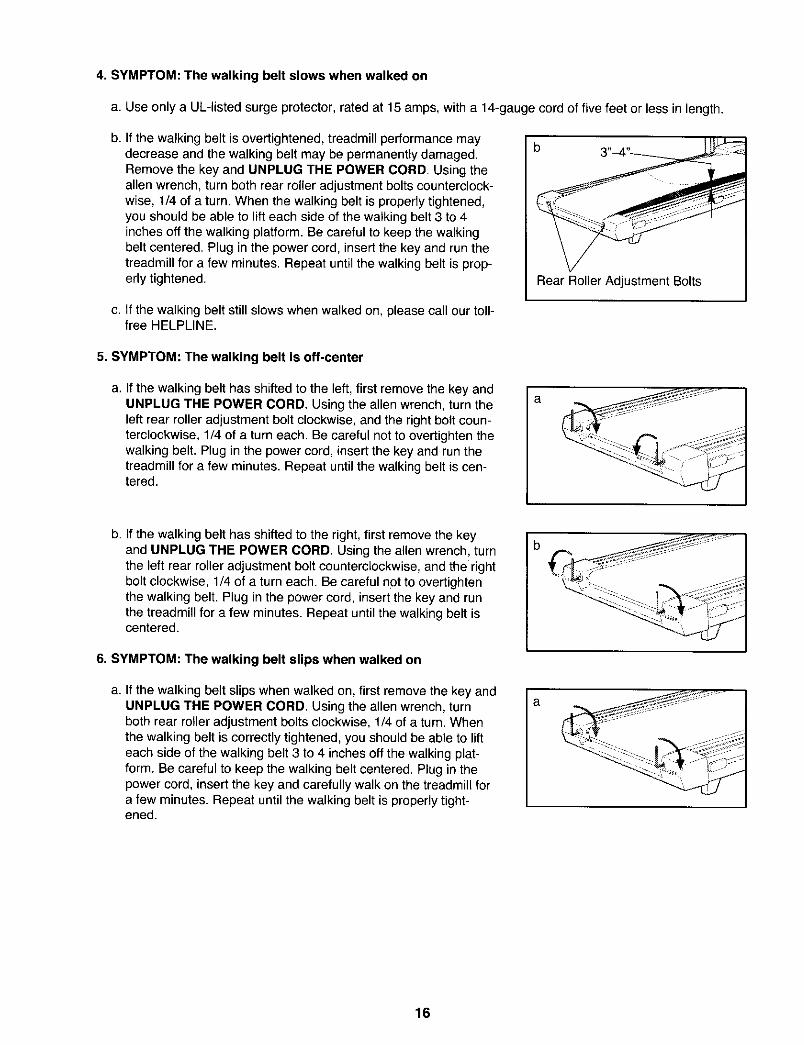
4. SYMPTOM: The walking belt slows when walked on
a. Use only a UL-listed surge protector, rated at 15 amps, with a 14-gauge cord of five feet or less in length.
b. If the walking belt is overtightened, treadmill performance maydecrease and the walking belt may be permanently damaged.Remove the key and UNPLUG THE POWER CORD. Using theallen wrench, turn both rear roller adjustment bolts counterclock-wise, 1/4 of a turn. When the walking belt is properly tightened,you should be able to lift each side of the walking belt 3 to 4inches off the walking platform. Be careful to keep the walkingbelt centered. Plug in the power cord, insert the key and run thetreadmill for a few minutes. Repeat until the walking belt is prop-erly tightened. Rear Roller Adjustment Bolts
c. If the walking belt still slows when walked on, please call our toll-free HELPLINE.
5. SYMPTOM: The walking belt is off-center
a. If the walking belt has shifted to the left, first remove the key andUNPLUG THE POWER CORD. Using the allen wrench, turn theleft rear roller adjustment bolt clockwise, and the right bolt coun-terclockwise, 1/4 of a turn each. Be careful not to overtighten thewalking belt. Plug in the power cord, insert the key and run thetreadmill for a few minutes. Repeat until the walking belt is cen-tered.
a
b. If the walking belt has shifted to the right, first remove the keyand UNPLUG THE POWER CORD. Using the allen wrench, turnthe left rear roller adjustment bolt counterclockwise, and the rightbolt clockwise, 1/4 of a turn each. Be careful not to overtightenthe walking belt. Plug in the power cord, insert the key and runthe treadmill for a few minutes. Repeat until the walking belt iscentered.
6. SYMPTOM: The walking belt slips when walked on
a. If the walking belt slips when walked on, first remove the key andUNPLUG THE POWER CORD. Using the allen wrench, turnboth rear roller adjustment bolts clockwise, 1/4 of a turn. Whenthe walking belt is correctlytightened, you should be able to lifteach side of the walking belt 3 to 4 inches off the walking plat-form. Be careful to keep the walking belt centered. Plug inthepower cord, insert the key and carefully walk on the treadmill fora few minutes. Repeat until the walking belt is properly tight-ened.
16
CONDITIONING GUIDELINES
, WARNING Before beginning this
or any exercise program, consult your physi-cian. This is especially important for ndiv du-als over the ageof 35 or individuals with pre-existing health problems.
The pulse sensor is not a medical device.Various factors, including your movement,may affect the accuracy of heart rate readings.The sensor is intended only as an exercise aidin determining heart rate trends in general.
The following guidelines will help you to plan your ex-ercise program. Remember--these are general guide-lines only. For more detailed exercise information, ob-tain a reputable book or consult your physician.
EXERCISE INTENSITY
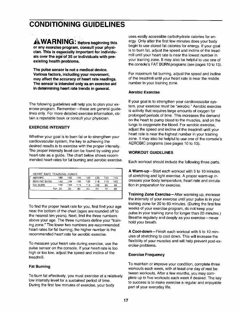
Whether your goal is to burn fat or to strengthen yourcardiovascular system, the key to achieving thedesired results is to exercise with the proper intensity.The proper intensity level can be found by using yourheart rate as a guide. The chart below shows recom-mended heart rates for fat burning and aerobic exercise.
HEART RATE TRA)NLNG ZONES
AEROBIC 165 155 145 140 130 125 115
MAX FAT BURN !45 138 !30 125 118 110 !OB
FAT BURN 125 12B 115 110 105 95 B0
ABe 20 30 40 50 B0 70 80
To find the proper heart rate for you, first find your agenear the bottom of the chart (ages are rounded off tothe nearest ten years). Next, find the three numbersabove your age. The three numbers define your "train-ing zone." The lower two numbers are recommendedheart rates for fat burning; the higher number is therecommended heart rate for aerobic exercise.
To measure your heart rate during exercise, use thepulse sensor on the console. If your heart rate is toohigh or too low, adjust the speed and incline of thetreadmill.
Fat Burning
To burn fat effectively, you must exercise at a relativelylow intensity level for a sustained period of time.During the first few minutes of exercise, your body
uses easily accessible carbohydrate calories for en-ergy. Only after the first few minutes does your bodybegin to use stored fat calories for energy. If your goalis to burn fat, adjust the speed and incline of the tread-mill until your heart rate is near the lowest number inyour training zone. It may also be helpful to use one ofthe console's FAT BURN programs (see pages 10 to 13).
For maximum fat burning, adjust the speed and inclineof the treadmill until your heart rate is near the middlenumber in your training zone.
Aerobic Exercise
If your goal is to strengthen your cardiovascular sys-tem, your exercise must be "aerobic." Aerobic exerciseis activity that requires large amounts of oxygen forprolonged periods of time. This increases the demandon the heart to pump blood to the muscles, and on thelungs to oxygenate the blood. For aerobic exercise,adjust the speed and incline of the treadmill until yourheart rate is near the highest number in your trainingzone. It may also be helpful to use one of the console'sAEROBIC programs (see pages 10 to 13).
WORKOUT GUIDELINES
Each workout should include the following three parts:
A Warm-up--Start each workout with 5 to 10 minutesof stretching and light exercise. A proper warm-up in-creases your body temperature, heart rate and circula-tion in preparation for exercise.
Training Zone Exercise--After warming up, increasethe intensityof your exercise untilyour pulse is in yourtrainingzone for 20 to 60 minutes. (During the first fewweeks of your exercise program, do not keep yourpulse in your training zone for longer than 20 minutes.)Breathe regularlyand deeply as you exercise--neverhold your breath.
A Cool-down--Finish each workout with 5 to 10 min-utes of stretching to cool down. This will increase theflexibility of your muscles and will help prevent post-ex-ercise problems.
Exercise Frequency
To maintain or improve your condition, complete threeworkouts each week, with at least one day of rest be-tween workouts. After a few months, you may com-plete up to five workouts each week if desired. The keyto success is to make exercise a regular and enjoyablepart of your everyday life.
17

SUGGESTED STRETCHES
The correct form for several basic stretches is shown at the right. Move slowly as you stretch--never bounce.
1. Toe Touch Stretch
Stand with your knees bent slightly and slowly bend forwardfrom your hips. Allow your back and shoulders to relax as youreach down toward your toes as far as possible. Hold for 15counts, then relax. Repeat 3 times. Stretches: Hamstrings,back of knees and back.
2. Hamstring Stretch
Sit with one leg extended. Bring the sole of the opposite foottoward you and rest it against the inner thigh of your extendedleg. Reach toward your toes as far as possible. Hold for 15counts, then relax. Repeat 3 times for each leg. Stretches:Hamstrings, lower back and groin.
3. Calf/Achilles Stretch
With one leg in front of the other, reach forward and place yourhands against a wall. Keep your back leg straight and yourback foot flat on the floor. Bend your front leg, lean forward andmove your hips toward the wall. Hold for 15 counts, then relax.Repeat 3 times for each leg. To cause further stretching of theachilles tendons, bend your back leg as well. Stretches:Calves, achilles tendons and ankles.
4. Quadriceps Stretch
With one hand against a wall for balance, reach back andgrasp one foot with your other hand. Bring your heel as closeto your buttocks as possible. Hold for 15 counts, then relax.Repeat 3 times for each leg. Stretches: Quadriceps and hipmuscles.
5. Inner Thigh Stretch
Sit with the soles of your feet together and your knees outward.Pull your feet toward your groin area as far as possible. Holdfor 15 counts, then relax. Repeat 3 times. Stretches:Quadriceps and hip muscles.
2
4
18

PART LIST--Model No. 831.297792 R0299A
Key Key KeyNo. Qty. Description No. Qty. Description No. Qty. Description
1 1 Motor Belt 51 1 Front Belly Pan2 1 Pulley/Flywheel/Fan 52 1 Power Supply3 4 Motor Nut 53 2 Cable Tie Clamp4* 1 Motor/Pulley/Fly./Fan 54 1 Cable Tie5 3 Incline Motor Bolt 55 1 Walking Belt6 1 Incline Motor Spacer 56 2 Roller Guard7 1 Incline Motor 57 1 Rear Roller8 1 Stop Bracket 58 2 Rear Isolator9 1 Small Nut 59 2 Rear Foot10 2 Star Washer 60 11 Rear Foot Screw11 1 Optic Switch 61 1 Ground Wire12 1 Frame 62 3 Ground Wire Screw13 1 Small Bolt 63 1 Belly Pan14 1 Incline Optic Disk 64 1 Rear Endcap15 8 Incline Motor Nut 65 2 Rear Roller Bolt16 16 Screw 66 1 Motor17 4 Plastic Stand-Off 67 1 Latch Decalt8 2 Hood Bracket (short) 68 2 Rear Platform Screw19 2 Hood Bracket (long) 69 1 Access Plate20 2 Warning Decal 70 1 Latch Catch21 1 Reed Switch 71 1 Walking Platform22 1 Reed Switch Clip 72 5 8" cable Tie23 1 Motor/Controller Wire 73 4 4" cable Tie24 1 Controller 74 1 Left Handrail25 1 Electronics Bracket 75 2 Handrail Endcap26 1 Circuit Breaker 76 7 Reed Switch Screw27 1 Power Cord 77 1 Storage Latch28 1 Power Cord Grommet 78 4 Handrail Bolt29 1 On/Off Switch 79 2 Small Upright Plug30 1 Inlet Bracket 80 4 Cage Nut31 1 Incline Leg 81 4 Motor Star Washer32 2 Frame Pivot Bolt 82 1 Upright33 2 Frame Pivot Spacer 83 2 Incline Pivot Bolt34 1 Upright Wire Harness 84 2 Incline Pivot Washer35 1 Front Roller Adj. Bolt 85 1 Right Handrail36 7 Washer 86 2 Wheel Bolt37 1 Choke 87 1 Console Base38 4 Motor Bolt 88 1 Console39 4 Cap Screw 89 4 Pulse Sensor Plate40 1 Left Foot Rail Cap 90 1 Key/Clip41 2 Foot Rail 91 1 Incline Motor Plate42 1 Front Roller/Pulley 92 2 Pulse Bar Bolt43 1 Magnet 93 4 Hood Screw44 6 Platform Screw 94 1 Motor Hood45 4 Isolator 95 2 Front Wheel46 4 Isolator Screw 96 1 Pulse Bar47 17 Belly Pan Fastener 97 4 Base Pad48 1 Console Wire Harness 98 8 Console Screw49 2 Belt Guide 99 1 Wrench Clip50 1 Console Cover 100 1 Allen Wrench
101 8 Short Screw102 1 Front Roller Adj. Nut103 2 Extension Leg104 2 Extension Leg Cap105 1 Shock106 1 Incline Spacer107 1 Incline Motor Shield108 1 Book Holder109 1 Right Foot Rail Cap110 1 Plastic Shield111 2 Foot Rail Insert112 1 Motor Tension Nut113 1 Motor Tension Bolt114 4 Long Screw# 1 8" Blue Wire, 2 F# 1 4" Blue Wire, 2 F# 1 10" White Wire, 2 F# 1 4" White Wire, M/F# 1 9" Wire Harness# 1 4" Black Wire, 2 F# 1 4" Green Wire# 1 8" Green/Yellow Wire# 1 User's Manual
* Includes all parts shown in the box# These parts are not illustrated
19

EXPLODED DRAWING-- Model No. 831.297792 R0299,_
65
! 17 :
76

EXPLODED DRAWING-- Model No. 831.297792 Ro299A
/.,
36\
I
77
9?
50
"!
9_
,/ / /
• /
/
93

SEARSModel No. 831.297792
QUESTIONS?
If you find that:
• you need help assembling oroperating the PROFORM J6sitreadmill
• a part is missing
• or you need to schedule repairservice
call our toll-free HELPLINE
1-800-736-6879Monday-Saturday, 7 am-7 pmCentral Time (excluding holidays)
REPLACEMENTPARTS
If parts become worn and needto be replaced, call the followingtoll-free number
1-800-FON-PART(1-800-366-7278)
The model number and serial number of your PROFORM _'J6sitreadmill are listed on a decal attached to the frame. See the frontcover of this manual to find the location of the decal.
All replacement parts are available for immediate purchase orspecial order when you visit your nearest SEARS Service Center.To request service or to order parts by telephone, call the toll-freenumbers listed at the left.
When requesting help or service, or ordering parts, please beprepared to provide the following information:
• The NAME OF THE PRODUCT (PROFORM " J6si treadmill)
• The MODEL NUMBER OF THE PRODUCT (831.297792)
• The KEY NUMBER AND DESCRIPTION OF THE PART (see theEXPLODED DRAWING and PART LIST included in this manual)
FULL 90 DAY WARRANTY
For 90 days from the date of purchase, if failure occurs due to defect in material or workmanship in thisSEARS TREADMILL EXERCISER, contact the nearest SEARS Service Center throughout the UnitedStates and SEARS will repair or replace the TREADMILL EXERCISER, free of charge.
This warranty does not apply when the TREADMILL EXERCISER is used commercially or for rental pur-poses.
This warranty gives you specific legal rights, and you may also have other rights which vary from stateto state.
SEARS, ROEBUCK AND CO., DEPT. 817WA, HOFFMAN ESTATES, IL 60179
Part No. 153152 JO0209-C R0299A Printed in USA © 1999 Sears, Roebuck and Co.