Embed Size (px)
Citation preview
ApplianX IP Gateway User Guide
Version 2.1 – 19/05/2010
2 of 60
Contents
APPLIANX IP GATEWAY USER GUIDE ...................................... 1
1.0 GETTING STARTED............................................................... 4
1.1 How to use this guide ....................................................................................... 4
1.2 Prerequisites ..................................................................................................... 4
1.3 L.E.Ds ................................................................................................................. 4
1.4 Setting up the gateway ..................................................................................... 4
1.5 Logging in to the web interface ........................................................................ 4
1.6 First time use ..................................................................................................... 6
1.7 The Setup Wizard ............................................................................................ 10
1.8 The Main Menu ................................................................................................ 11
1.9 The Overview Page ......................................................................................... 12
1.11 Networking ..................................................................................................... 13 1.11.1 Network settings via the web interface ...................................................... 13 1.11.2 Network settings via USB Flash Memory ................................................... 16
2.0 CONFIGURING THE GATEWAY .......................................... 17
2.1 Gateway Configuration ................................................................................... 17 2.1.1 Gateway Configuration Page Descriptions .................................................. 17 2.1.2 General Configuration Information ............................................................... 17 2.1.3 Editing Trunks ............................................................................................. 18 2.1.3.1 Editing a SIP Trunk .................................................................................. 20 2.1.3.2 Editing a TDM Trunk ................................................................................ 20 2.1.3.2.1 Editing a TDM Trunk Protocol ................................................................ 21 2.1.4 Endpoints .................................................................................................... 23 2.1.5 Groups ........................................................................................................ 25 2.1.5.1 Adding or Editing a Group ........................................................................ 25 2.1.6 Routes......................................................................................................... 27 2.1.7 Clocking ...................................................................................................... 30 2.1.8 SIP .............................................................................................................. 31 2.1.9 Codecs ........................................................................................................ 34 2.1.10 Test ........................................................................................................... 34
2.2. Backing up and Restoring Configurations ................................................... 36
2.3 Restoring an ApplianX Using and ApplianX Rescue Disk ............................ 37
3 of 60
3.0 ADDITIONAL INFORMATION .............................................. 39
3.1 Routing Overview ............................................................................................ 39
3.2 X.509 Certificates ............................................................................................ 40
3.3 Creating X.509 certificates using OpenSSL................................................... 41
3.4 HTTPS .............................................................................................................. 45
3.5 Secure SIP over TLS ....................................................................................... 46
3.6 Software Updates ............................................................................................ 49 Getting update images ......................................................................................... 49 Getting ax-img-tool ............................................................................................... 49 Validating update images ..................................................................................... 49 To apply an update image using HTTP ................................................................ 50 To apply an update using USB ............................................................................. 52
4.0 DIAGNOSTICS ..................................................................... 54
4.1 Remote Logging .............................................................................................. 54
4.1 Diagnostic Log ................................................................................................ 55
5.0 TROUBLESHOOTING .......................................................... 56
5.1 Logging into the remote interface .................................................................. 56 5.1.1 I can‟t get access to the ApplianX Gateway Web Interface .......................... 56 5.1.2 I log on but the overview screen has errors at the top ................................. 56 5.1.3 I get a warning saying that the gateway cannot. .......................................... 56
5.2 Making Calls through the Gateway ................................................................ 56 5.2.1 I can‟t make a call from the TDM side of the Gateway to an IP client. ......... 56
5.3 Configuring the Gateway ................................................................................ 58 5.3.1 I have made changes to the configuration but they don‟t seem to have any effect. ................................................................................................................... 58 5.3.1 I used the wizard to create an initial configuration but I have an error saying that there is no active configuration. ..................................................................... 58
6.0 GLOSSARY .......................................................................... 59
4 of 60
1.0 Getting Started 1.1 How to use this guide The ApplianX gateway interface has been designed to be intuitive. However we still recommend that new users read sections 1-3 of this guide before trying to set up a gateway for the first time. Sections 2 and 3 are a reference for those that have used the gateway before while sections 4 and 5, Diagnostics and Troubleshooting, should only be needed if problems have been encountered.
1.2 Prerequisites The ApplianX gateway is configured via a Web Interface. Therefore a device with a web browser that supports TCP/IP will be needed to connect to the ApplianX. Also any networking cables and switches needed to allow this connection will be needed. Note that the Traffic connection of the IP Gateway needs to be connected to an Ethernet Switch and not to a Hub.
1.3 L.E.Ds There are a number of LED‟s on the front of the ApplianX that are there to help during the installation and running of the ApplianX.
Halted – This red LED indicates a serious error. If this has occurred in any circumstance other than restarting or shutting down the ApplianX then a serious error has occurred and a restart of the unit will be required.
Error – This red LED indicates that the ApplianX has an error condition that may be resolved. Log into the ApplianX via the web interface to identify the nature of the problem
Activity – This blue LED will flash when the ApplianX is starting up and also when the ApplianX is processing calls.
Ready – This Green LED is lit when the ApplianX application is running.
Startup/Initialising – This Yellow LED indicates that the ApplianX is starting. Note that user interaction may be needed via the web interface to complete startup.
1.4 Setting up the gateway There are a number of steps that need to be carried out before the Gateway can be used to service calls. The Setup Wizard is designed to create a basic configuration.
1.5 Logging in to the web interface The ApplianX Gateway should be powered up with LAN cables connecting the VoIP traffic port and the Admin port to the network. The ApplianX will take approximately one minute and twenty seconds to bring up the web interface. For versions of software 2.1.0 and later the ApplianX will have the static IP address 192.168.1.100. For earlier versions please consult earlier versions of the documentation. Connect a PC directly to the ApplianX admin port with an Ethernet cable. Set the PC to have the static IP address 192.168.1.1 with a net mask of 255.255.255.0. By typing 192.168.1.100 into the web browser the ApplianX administration interface should be accessible. Change the static IP address to something suitable for the network it will be used in. Once set up in a network the ApplianX will be accessible via the ApplianX Search Tool.
5 of 60
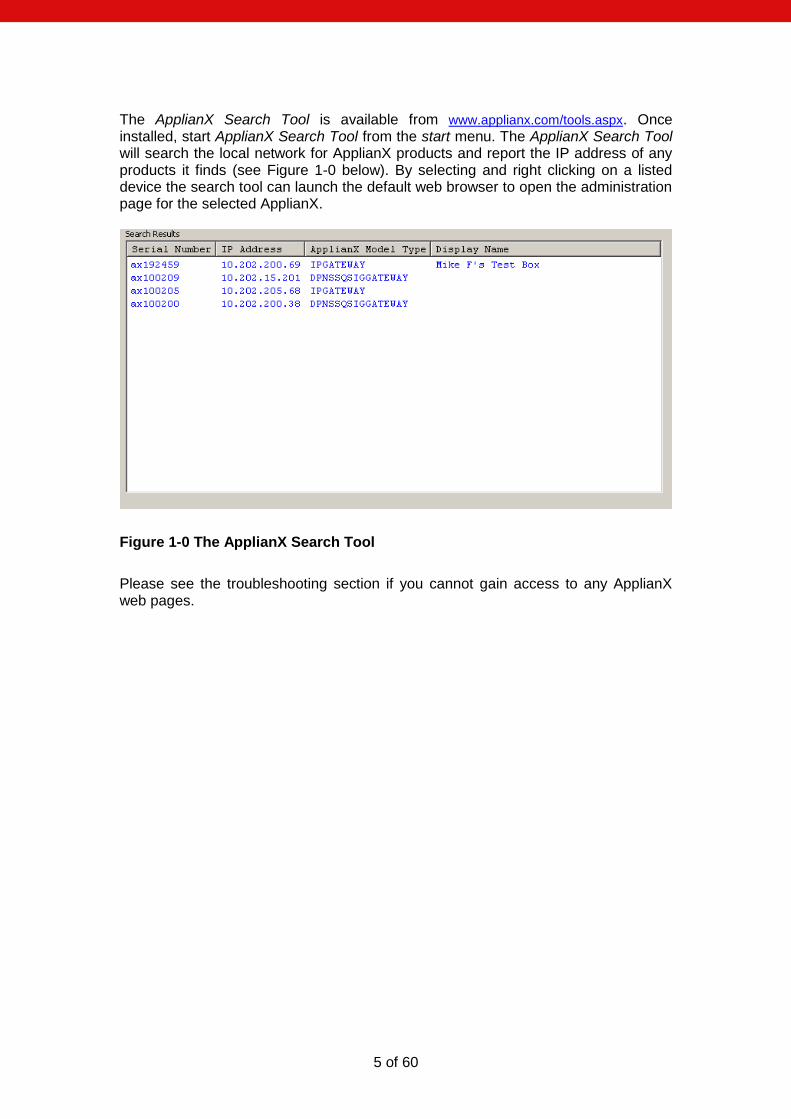
The ApplianX Search Tool is available from www.applianx.com/tools.aspx. Once installed, start ApplianX Search Tool from the start menu. The ApplianX Search Tool will search the local network for ApplianX products and report the IP address of any products it finds (see Figure 1-0 below). By selecting and right clicking on a listed device the search tool can launch the default web browser to open the administration page for the selected ApplianX.
Figure 1-0 The ApplianX Search Tool
Please see the troubleshooting section if you cannot gain access to any ApplianX web pages.
6 of 60
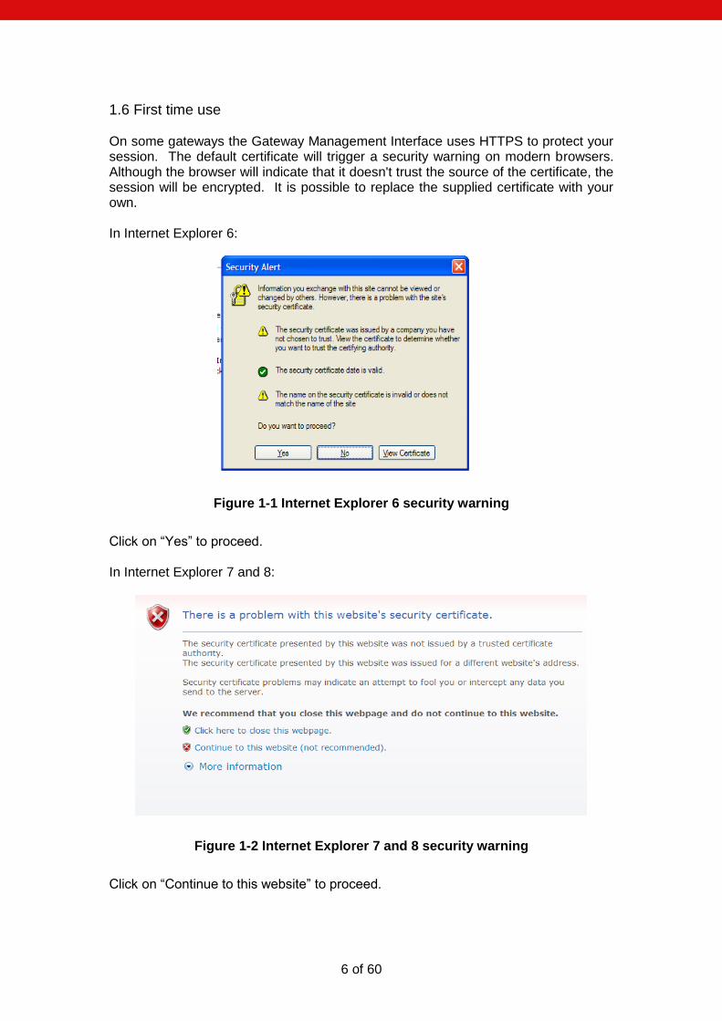
1.6 First time use On some gateways the Gateway Management Interface uses HTTPS to protect your session. The default certificate will trigger a security warning on modern browsers. Although the browser will indicate that it doesn't trust the source of the certificate, the session will be encrypted. It is possible to replace the supplied certificate with your own. In Internet Explorer 6:
Figure 1-1 Internet Explorer 6 security warning
Click on “Yes” to proceed. In Internet Explorer 7 and 8:
Figure 1-2 Internet Explorer 7 and 8 security warning
Click on “Continue to this website” to proceed.
7 of 60
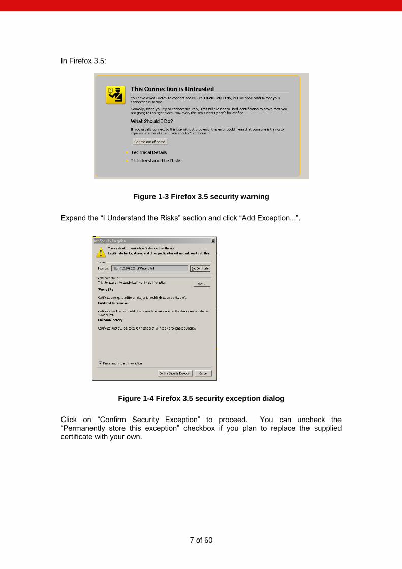
In Firefox 3.5:
Figure 1-3 Firefox 3.5 security warning
Expand the “I Understand the Risks” section and click “Add Exception...”.
Figure 1-4 Firefox 3.5 security exception dialog
Click on “Confirm Security Exception” to proceed. You can uncheck the “Permanently store this exception” checkbox if you plan to replace the supplied certificate with your own.
8 of 60
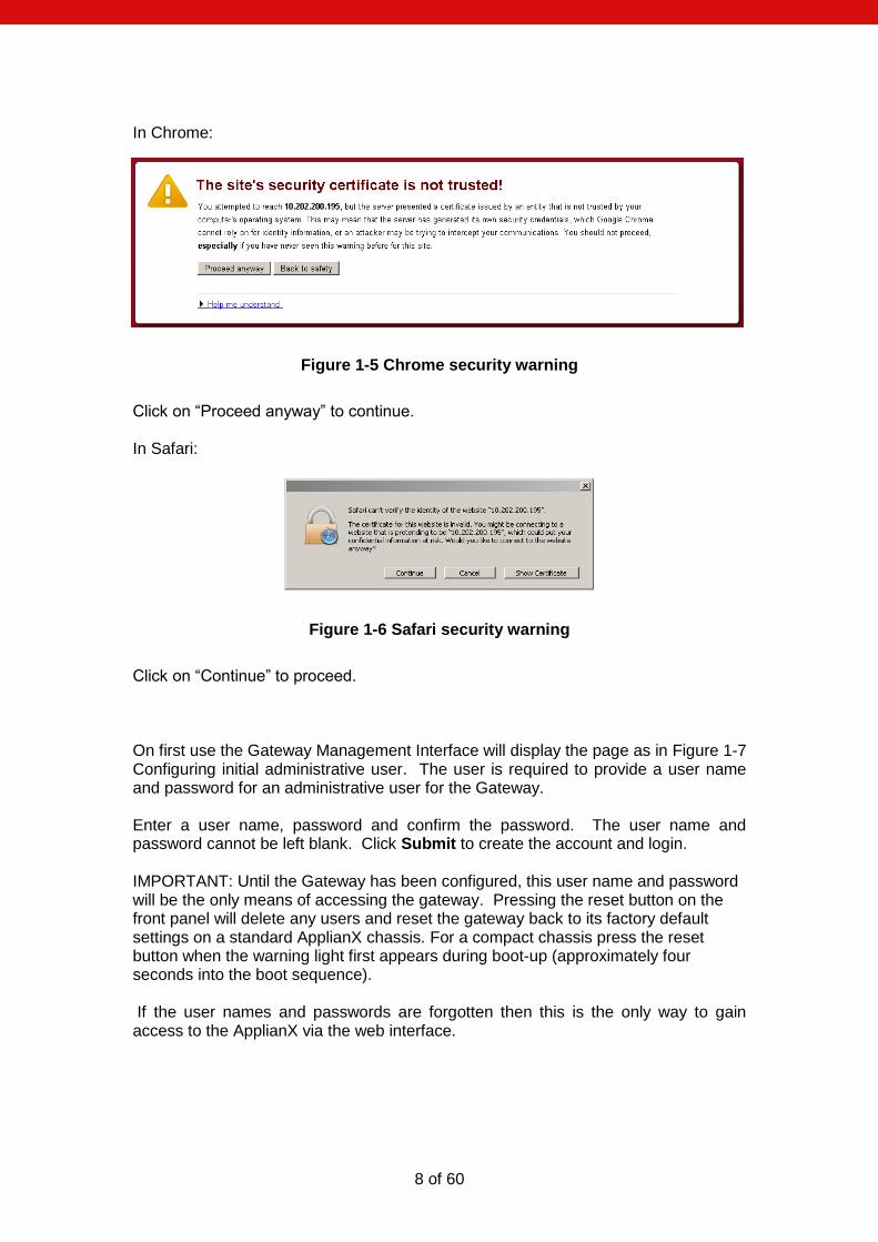
In Chrome:
Figure 1-5 Chrome security warning
Click on “Proceed anyway” to continue. In Safari:
Figure 1-6 Safari security warning
Click on “Continue” to proceed. On first use the Gateway Management Interface will display the page as in Figure 1-7 Configuring initial administrative user. The user is required to provide a user name and password for an administrative user for the Gateway. Enter a user name, password and confirm the password. The user name and password cannot be left blank. Click Submit to create the account and login. IMPORTANT: Until the Gateway has been configured, this user name and password will be the only means of accessing the gateway. Pressing the reset button on the front panel will delete any users and reset the gateway back to its factory default settings on a standard ApplianX chassis. For a compact chassis press the reset button when the warning light first appears during boot-up (approximately four seconds into the boot sequence). If the user names and passwords are forgotten then this is the only way to gain access to the ApplianX via the web interface.

9 of 60
Figure 1-7 Configuring initial administrative user
10 of 60
1.7 The Setup Wizard The Setup Wizard is accessed from the Gateway menu. It is also automatically invoked the first time the Gateway is used. The setup wizard allows the creation of a basic configuration, prompting for the most commonly required and important configuration details. Default values or reasonable values are used wherever possible. At any time, Cancel can be selected to return to the main Gateway Overview page. No configuration is stored until the user selects Apply on the final wizard page. A wizard created new configuration will have:
3 Endpoints
Default SIP Endpoint (Will have no associated IP address initially)
ApplianX IP Gateway Self (will match calls from the ApplianX to itself, e.g. as sometimes made during SIP transfer)
Proxy (Will have an address if given in the wizard)
3 Groups
“TDM Trunks” containing all the TDM trunks
“Default Incoming SIP group”
“Proxy group”
No routing rules defined and the “Use same rules for all groups” option turned on.
The “Accept calls from unknown endpoints” option will be turned off.
TDM clocking configured to use any good available TDM trunk or otherwise to fallback to local clocking
SIP listening on UDP and TCP ports 5060
using UDP for outgoing calls
enabling DTMF as RFC2833
G.711 a-law and G.711 mu-law codecs enabled
TLS and SRTP disabled (An option on some gateways) At the end of the wizard your web browser will be redirected to the “Edit Configurations” page. Here you have a list of all configurations that have been setup on the ApplianX. Note that if this is the first time a configuration has been created then the new configuration will be listed in the “Available configurations” list. The configuration must be activated to bring it into use. This is done by selecting Use for the required configuration.
11 of 60
1.8 The Main Menu On the left of the screen at all times, apart from when the wizard is running, you will be able to access all the configuration and status pages.
Status o Overview – A page with some basic gateway call counts and a list of
actions required of the gateway administrator. o Alarms – This page will display any Layer 1 or Layer 2 alarms on the
TDM trunks. It will also allow the masking of these alarms. o Calls – A graphical display of all the call activity on the ApplianX
Gateway. o Call Log - A recent history of calls that the gateway has attempted to
route. This page can be very useful for diagnosing issues during the set up phase for the gateway.
o Trunk Status – This has detailed information on the SIP and TDM trunks
System Configuration o Global Configuration – This allows the box to be named
System Time – This allows the setting of the clock to local time and NTP configuration.
Software Update – From this page a check can be made for software updates. See section 1.8 for more information.
HTTPS Configuration – This allows you to view information about the HTTPS certificate currently in use and replace it if required (on some gateways).
SIP TLS Configuration – This allows you to configure TLS certificates.
System Users – This allows the addition of new administrators to the ApplianX and the setting of their privileges.
Backup and Restore – This allows configurations to be saved and restored to the ApplianX.
o Networking – This allows the user to choose static IP addresses or DHCP mode
SNMP – This allows the configuration of the SNMP settings. From here you can enter the IP address of the host you wish to send traps to and enable them. Also here you can turn on the traps for the disconnecting of the Ethernet ports. Similar options are available for the TDM ports through the TDM configuration options.
o Setup Wizard – This allows the setup wizard to be run to create a skeleton configuration
o SIP Credentials – This allows the configuration of details to allow the gateway to respond appropriately when challenged for authorisation information.
Gateway Configuration o Edit Configurations – This takes you to the main configuration
overview where different gateway configurations can be selected and edited. All aspects of the gateway from Codecs and SIP set up to routing rules and groups can be edited here.
o Cause Mappings – Here the clearing causes between SIP, QSIG and DPNSS can be changed from their default values.
12 of 60
Diagnostics o Remote Logging – This allows the administrator to point the syslog
output from the ApplianX to an external syslog client or ApplianX Trace Tool. This is for advanced users and support teams.
o Watchdog Status – This reveals the status of the “watchdogs” running on the ApplianX. They are here to look for any elements that have failed or are reporting problems. This is for advanced users and support teams.
o Restart – This is used to “reboot” the ApplianX. Note that rebooting will cause all contact to be lost with the ApplianX through the user interface.
o Diagnostic Log – This provides a high level overview of gateway process and can be used for debugging purposes.
o About – This gives build information on the ApplianX. o Endpoint Status – This page will list the status of those IP endpoints
that have been configured for monitoring o Hardware – This displays the version and status of the hardware used
in the ApplianX.
Account o Log Out – This allows the current user to log out of the ApplianX
administration screens. o Change Password – This allows the current administration user to
change their password.
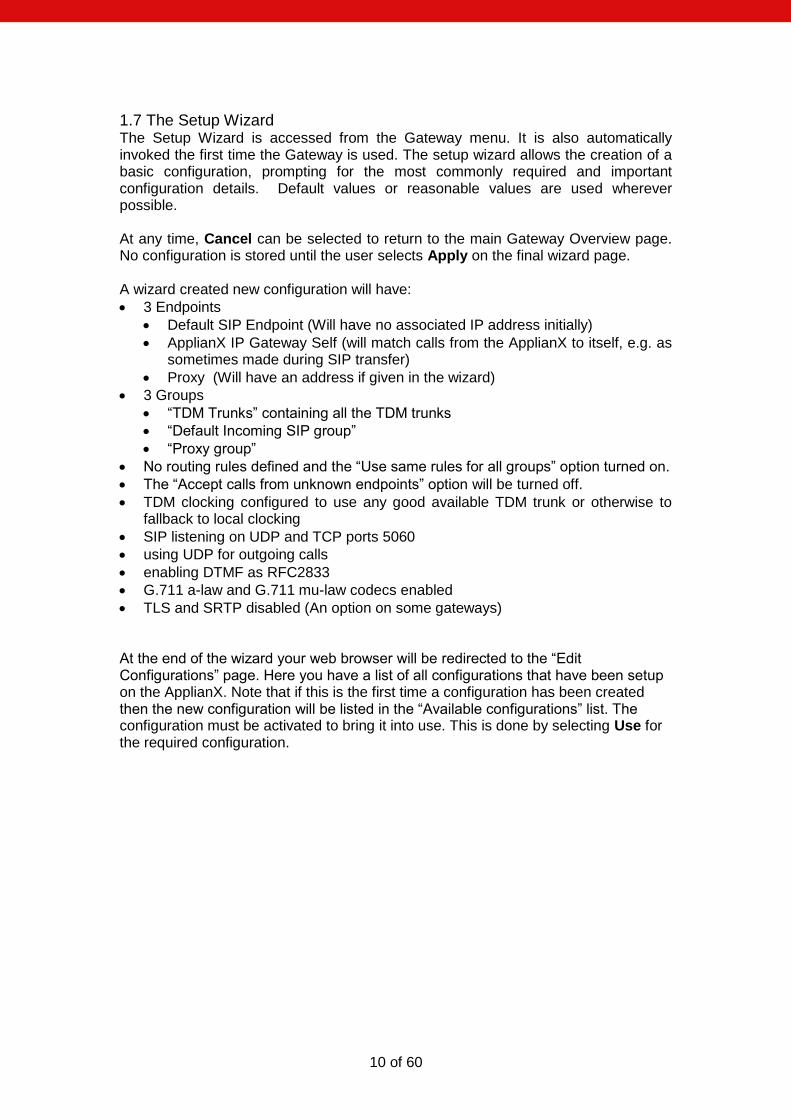
1.9 The Overview Page The overview page gives some basic stats for the gateway such as total incoming and outgoing call counts. At the bottom of this page will be a list of actions that the gateway is flagging for the administrator.
Figure 1-8 The Overview page
13 of 60
As you can see in the above example the Gateway is telling us that we have Layer 1 errors on all trunks. In this case it is because we have not connected any TDM trunks to the gateway yet.
1.11 Networking The ApplianX IP Gateway standard chassis requires 3 IP addresses. The compact chassis requires 2 IP addresses. By default the admin port is set to a static IP addresses of 192.168.1.100, the signalling interface is set to 10.202.100.4 and the media interface is set to DHCP. The gateway should only actually be deployed using static IP addresses. Note that if DHCP is selected and there is no DHCP server on the network the ApplianX will use Zeroconf technologies to get IP addresses and to provide access to the unit. There are 2 methods to change the IP settings. One via the web interface and one that can be done via a USB flash memory device.
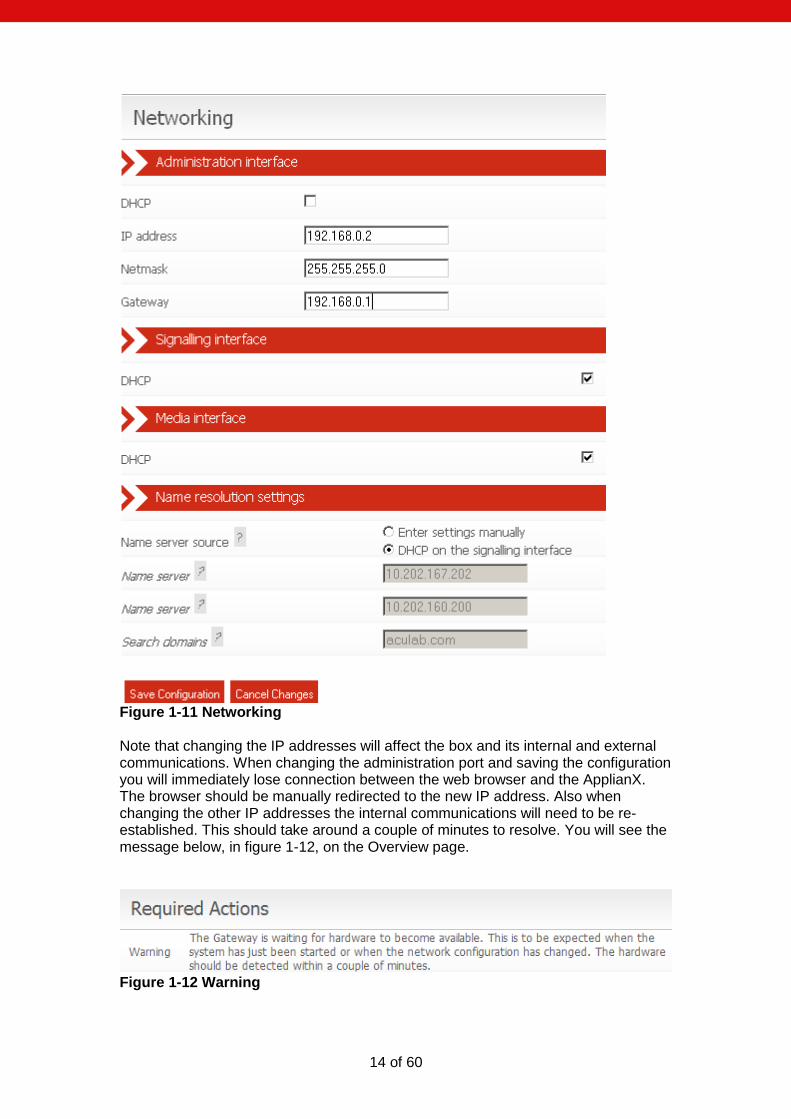
1.11.1 Network settings via the web interface The IP addresses can be manually set to static addresses by selecting Networking from the menu on the left. Here the 3 interfaces can be selected to be set up via DHCP or can be set to static IP addresses as shown below in figure1-11.
14 of 60
Figure 1-11 Networking Note that changing the IP addresses will affect the box and its internal and external communications. When changing the administration port and saving the configuration you will immediately lose connection between the web browser and the ApplianX. The browser should be manually redirected to the new IP address. Also when changing the other IP addresses the internal communications will need to be re-established. This should take around a couple of minutes to resolve. You will see the message below, in figure 1-12, on the Overview page.
Figure 1-12 Warning

15 of 60
Finally the options for name resolution can be setup on this page. Servers may be manually entered or DHCP on the signalling interface may be selected.

16 of 60
1.11.2 Network settings via USB Flash Memory The ApplianX will check for the presence of a USB device when it is booting up. If it finds one then it will look on this device for User Defined IP settings and will configure the unit to come into service with those settings. Note that using this method it takes a few minutes longer for the unit to come up and change the IP addresses to those configured. On the USB flash device create a directory called applianx_net in the root. Place 3 files in this directory called admin, media and signalling. Note that these files have no extensions so be careful with the editor you are using in case it adds an extension for you. Within each of these files you need to put the information to set the static IP address. [Config] ip = 10.202.165.169 netmask = 255.255.0.0 gateway = 10.202.100.254 or to set an interface to DHCP use. [Config] dhcp = 1
17 of 60
2.0 Configuring the Gateway
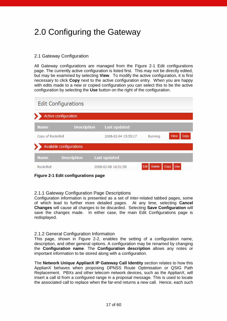
2.1 Gateway Configuration All Gateway configurations are managed from the Figure 2-1 Edit configurations page. The currently active configuration is listed first. This may not be directly edited, but may be examined by selecting View. To modify the active configuration, it is first necessary to click Copy next to the active configuration entry. When you are happy with edits made to a new or copied configuration you can select this to be the active configuration by selecting the Use button on the right of the configuration.
Figure 2-1 Edit configurations page
2.1.1 Gateway Configuration Page Descriptions Configuration information is presented as a set of inter-related tabbed pages, some of which lead to further more detailed pages. At any time, selecting Cancel Changes will cause all changes to be discarded. Selecting Save Configuration will save the changes made. In either case, the main Edit Configurations page is redisplayed.
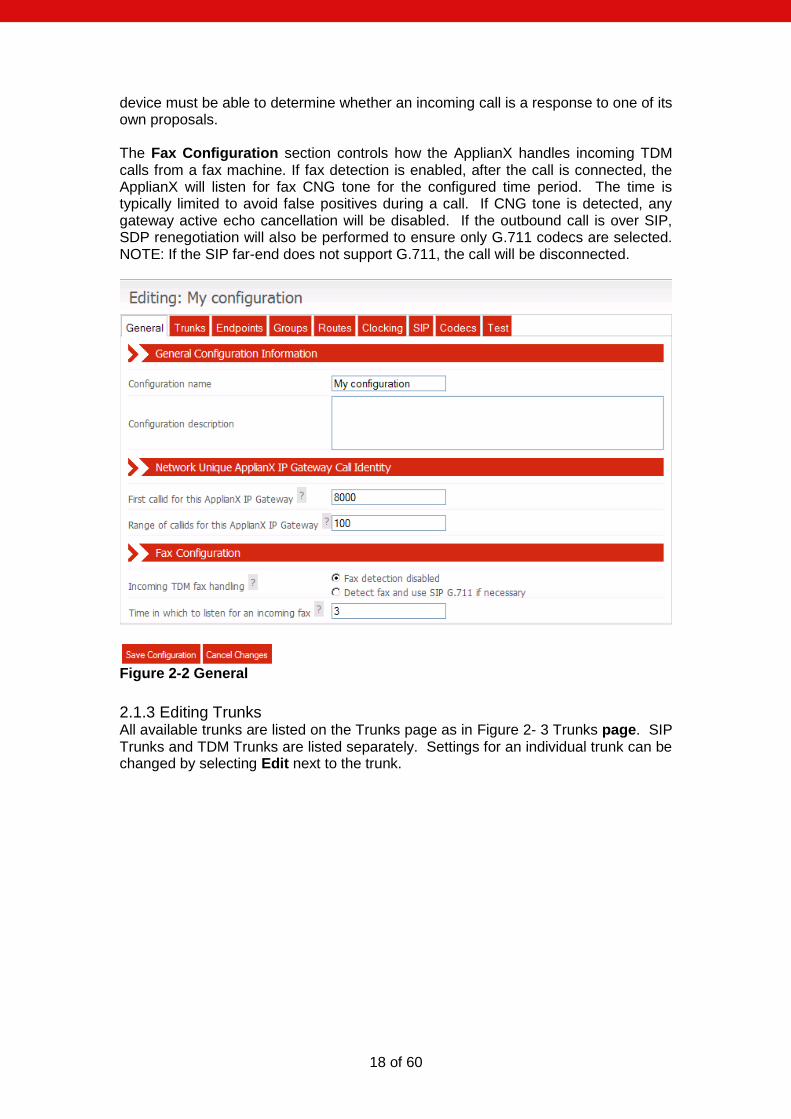
2.1.2 General Configuration Information This page, shown in Figure 2-2, enables the setting of a configuration name, description, and other general options. A configuration may be renamed by changing the Configuration name. The Configuration description allows any notes or important information to be stored along with a configuration. The Network Unique ApplianX IP Gateway Call Identity section relates to how this ApplianX behaves when proposing DPNSS Route Optimisation or QSIG Path Replacement. PBXs and other telecom network devices, such as the ApplianX, will insert a call id from a configured range in a proposal message. This is used to locate the associated call to replace when the far-end returns a new call. Hence, each such
18 of 60
device must be able to determine whether an incoming call is a response to one of its own proposals. The Fax Configuration section controls how the ApplianX handles incoming TDM calls from a fax machine. If fax detection is enabled, after the call is connected, the ApplianX will listen for fax CNG tone for the configured time period. The time is typically limited to avoid false positives during a call. If CNG tone is detected, any gateway active echo cancellation will be disabled. If the outbound call is over SIP, SDP renegotiation will also be performed to ensure only G.711 codecs are selected. NOTE: If the SIP far-end does not support G.711, the call will be disconnected.
Figure 2-2 General
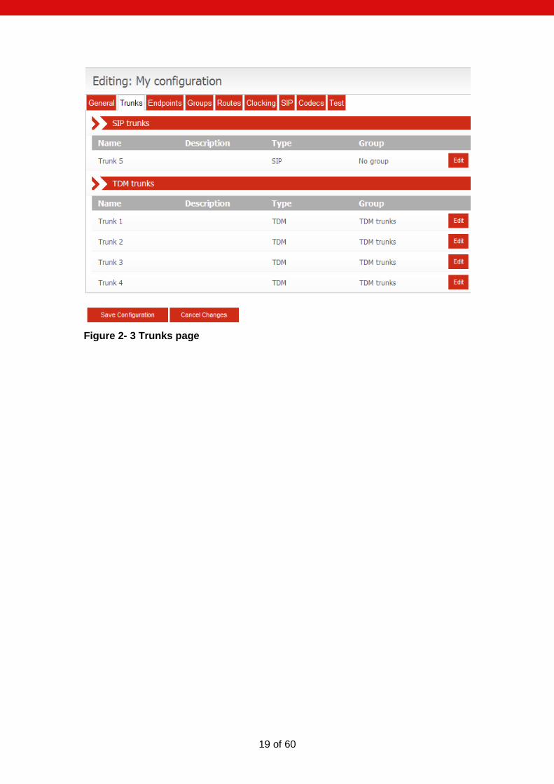
2.1.3 Editing Trunks All available trunks are listed on the Trunks page as in Figure 2- 3 Trunks page. SIP Trunks and TDM Trunks are listed separately. Settings for an individual trunk can be changed by selecting Edit next to the trunk.
19 of 60
Figure 2- 3 Trunks page
20 of 60
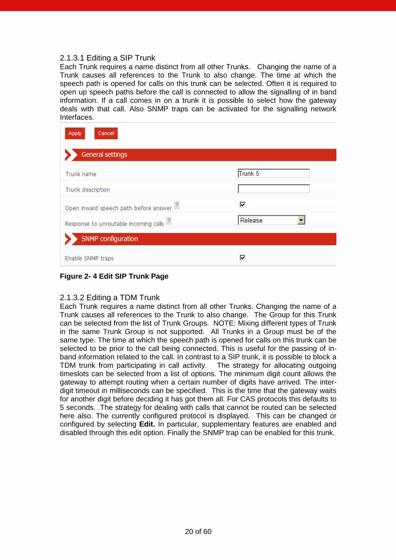
2.1.3.1 Editing a SIP Trunk Each Trunk requires a name distinct from all other Trunks. Changing the name of a Trunk causes all references to the Trunk to also change. The time at which the speech path is opened for calls on this trunk can be selected. Often it is required to open up speech paths before the call is connected to allow the signalling of in band information. If a call comes in on a trunk it is possible to select how the gateway deals with that call. Also SNMP traps can be activated for the signalling network Interfaces.
Figure 2- 4 Edit SIP Trunk Page
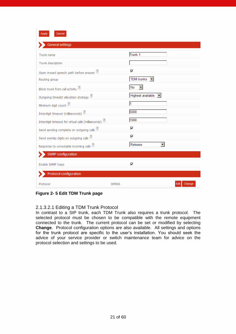
2.1.3.2 Editing a TDM Trunk Each Trunk requires a name distinct from all other Trunks. Changing the name of a Trunk causes all references to the Trunk to also change. The Group for this Trunk can be selected from the list of Trunk Groups. NOTE: Mixing different types of Trunk in the same Trunk Group is not supported. All Trunks in a Group must be of the same type. The time at which the speech path is opened for calls on this trunk can be selected to be prior to the call being connected. This is useful for the passing of in-band information related to the call. In contrast to a SIP trunk, it is possible to block a TDM trunk from participating in call activity. The strategy for allocating outgoing timeslots can be selected from a list of options. The minimum digit count allows the gateway to attempt routing when a certain number of digits have arrived. The inter-digit timeout in milliseconds can be specified. This is the time that the gateway waits for another digit before deciding it has got them all. For CAS protocols this defaults to 5 seconds. The strategy for dealing with calls that cannot be routed can be selected here also. The currently configured protocol is displayed. This can be changed or configured by selecting Edit. In particular, supplementary features are enabled and disabled through this edit option. Finally the SNMP trap can be enabled for this trunk.
21 of 60
Figure 2- 5 Edit TDM Trunk page
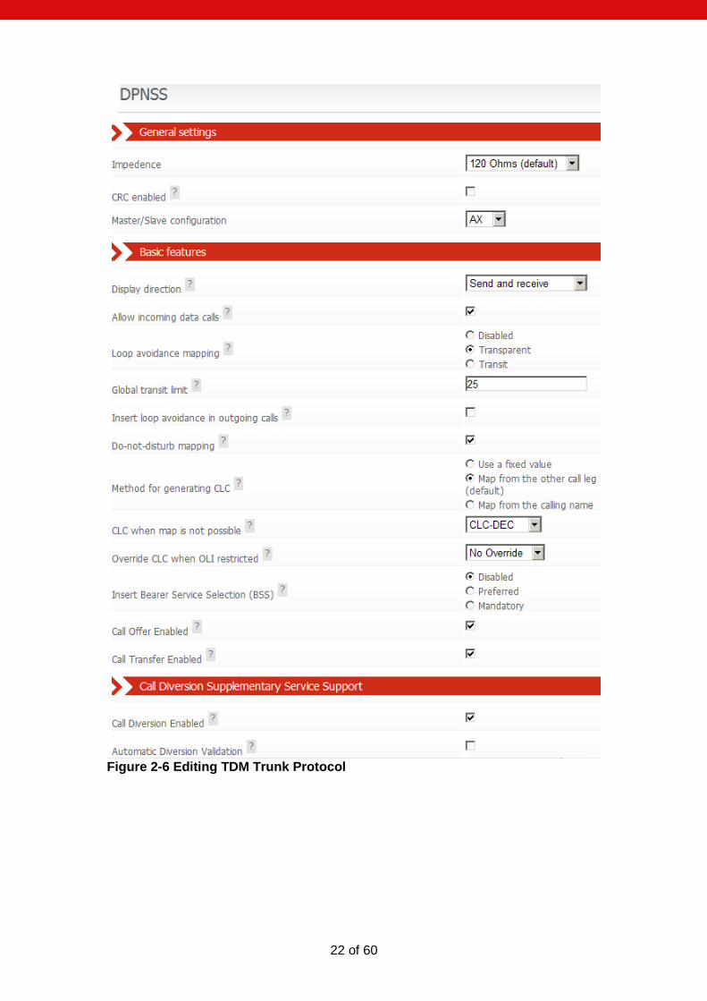
2.1.3.2.1 Editing a TDM Trunk Protocol In contrast to a SIP trunk, each TDM Trunk also requires a trunk protocol. The selected protocol must be chosen to be compatible with the remote equipment connected to the trunk. The current protocol can be set or modified by selecting Change. Protocol configuration options are also available. All settings and options for the trunk protocol are specific to the user‟s installation. You should seek the advice of your service provider or switch maintenance team for advice on the protocol selection and settings to be used.
22 of 60
Figure 2-6 Editing TDM Trunk Protocol
23 of 60
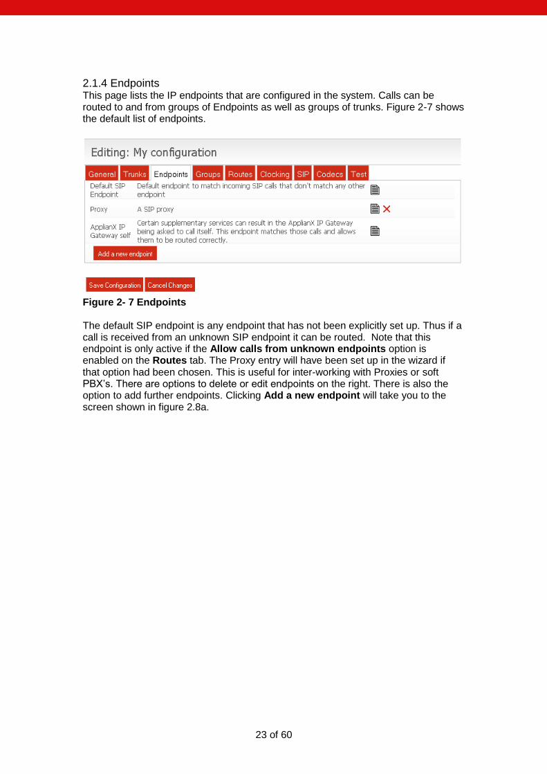
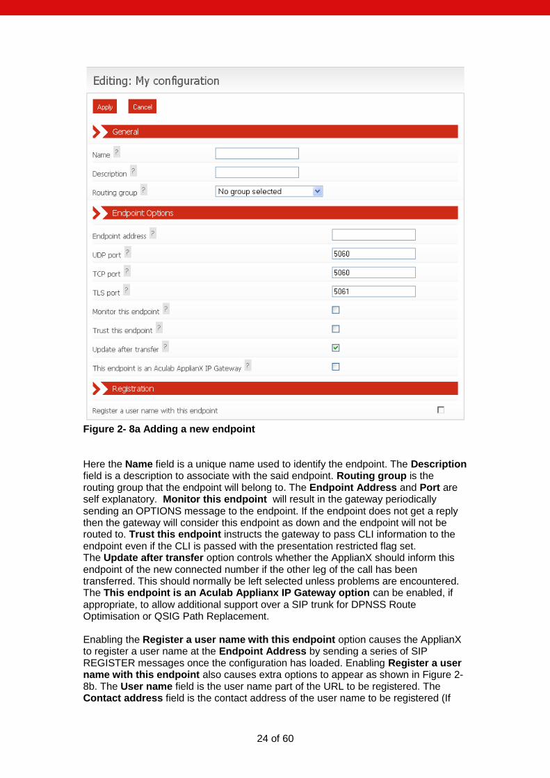
2.1.4 Endpoints This page lists the IP endpoints that are configured in the system. Calls can be routed to and from groups of Endpoints as well as groups of trunks. Figure 2-7 shows the default list of endpoints.
Figure 2- 7 Endpoints The default SIP endpoint is any endpoint that has not been explicitly set up. Thus if a call is received from an unknown SIP endpoint it can be routed. Note that this endpoint is only active if the Allow calls from unknown endpoints option is enabled on the Routes tab. The Proxy entry will have been set up in the wizard if that option had been chosen. This is useful for inter-working with Proxies or soft PBX‟s. There are options to delete or edit endpoints on the right. There is also the option to add further endpoints. Clicking Add a new endpoint will take you to the screen shown in figure 2.8a.
24 of 60
Figure 2- 8a Adding a new endpoint Here the Name field is a unique name used to identify the endpoint. The Description field is a description to associate with the said endpoint. Routing group is the routing group that the endpoint will belong to. The Endpoint Address and Port are self explanatory. Monitor this endpoint will result in the gateway periodically sending an OPTIONS message to the endpoint. If the endpoint does not get a reply then the gateway will consider this endpoint as down and the endpoint will not be routed to. Trust this endpoint instructs the gateway to pass CLI information to the endpoint even if the CLI is passed with the presentation restricted flag set. The Update after transfer option controls whether the ApplianX should inform this endpoint of the new connected number if the other leg of the call has been transferred. This should normally be left selected unless problems are encountered. The This endpoint is an Aculab Applianx IP Gateway option can be enabled, if appropriate, to allow additional support over a SIP trunk for DPNSS Route Optimisation or QSIG Path Replacement. Enabling the Register a user name with this endpoint option causes the ApplianX to register a user name at the Endpoint Address by sending a series of SIP REGISTER messages once the configuration has loaded. Enabling Register a user name with this endpoint also causes extra options to appear as shown in Figure 2-8b. The User name field is the user name part of the URL to be registered. The Contact address field is the contact address of the user name to be registered (If
25 of 60
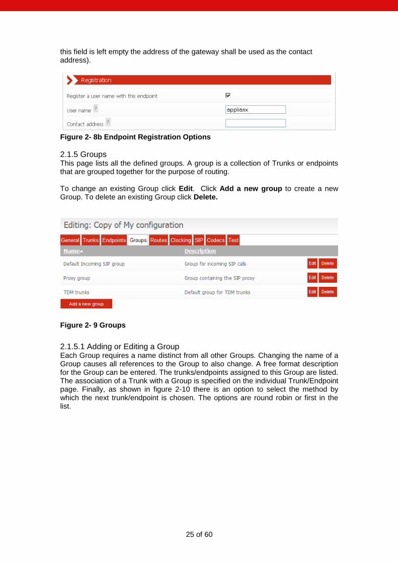
this field is left empty the address of the gateway shall be used as the contact address).
Figure 2- 8b Endpoint Registration Options
2.1.5 Groups This page lists all the defined groups. A group is a collection of Trunks or endpoints that are grouped together for the purpose of routing. To change an existing Group click Edit. Click Add a new group to create a new Group. To delete an existing Group click Delete.
Figure 2- 9 Groups
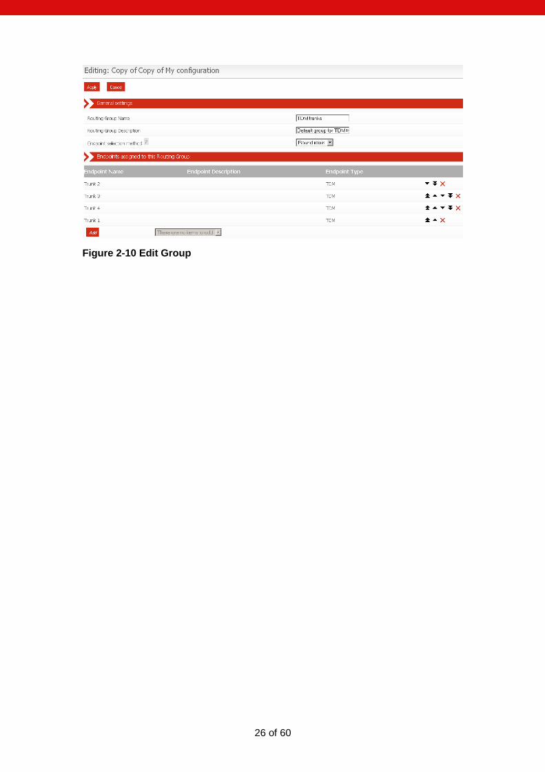
2.1.5.1 Adding or Editing a Group Each Group requires a name distinct from all other Groups. Changing the name of a Group causes all references to the Group to also change. A free format description for the Group can be entered. The trunks/endpoints assigned to this Group are listed. The association of a Trunk with a Group is specified on the individual Trunk/Endpoint page. Finally, as shown in figure 2-10 there is an option to select the method by which the next trunk/endpoint is chosen. The options are round robin or first in the list.
26 of 60
Figure 2-10 Edit Group
27 of 60
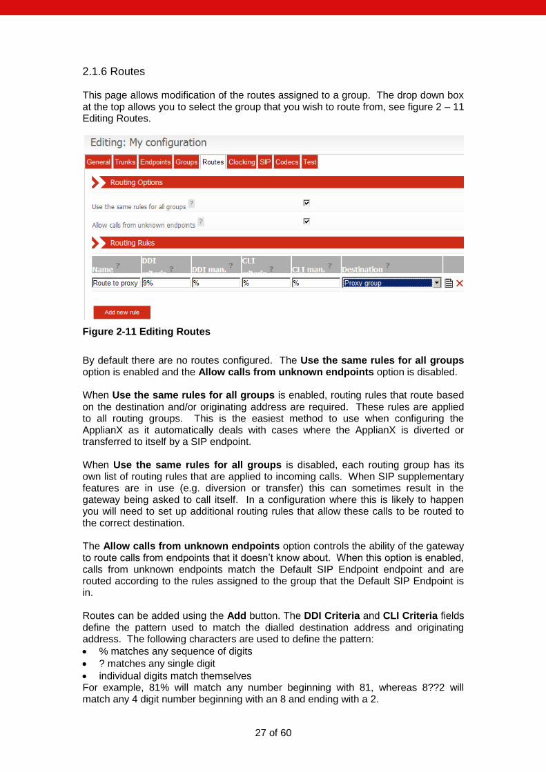
2.1.6 Routes This page allows modification of the routes assigned to a group. The drop down box at the top allows you to select the group that you wish to route from, see figure 2 – 11 Editing Routes.
Figure 2-11 Editing Routes
By default there are no routes configured. The Use the same rules for all groups option is enabled and the Allow calls from unknown endpoints option is disabled. When Use the same rules for all groups is enabled, routing rules that route based on the destination and/or originating address are required. These rules are applied to all routing groups. This is the easiest method to use when configuring the ApplianX as it automatically deals with cases where the ApplianX is diverted or transferred to itself by a SIP endpoint. When Use the same rules for all groups is disabled, each routing group has its own list of routing rules that are applied to incoming calls. When SIP supplementary features are in use (e.g. diversion or transfer) this can sometimes result in the gateway being asked to call itself. In a configuration where this is likely to happen you will need to set up additional routing rules that allow these calls to be routed to the correct destination. The Allow calls from unknown endpoints option controls the ability of the gateway to route calls from endpoints that it doesn‟t know about. When this option is enabled, calls from unknown endpoints match the Default SIP Endpoint endpoint and are routed according to the rules assigned to the group that the Default SIP Endpoint is in. Routes can be added using the Add button. The DDI Criteria and CLI Criteria fields define the pattern used to match the dialled destination address and originating address. The following characters are used to define the pattern:
% matches any sequence of digits
? matches any single digit
individual digits match themselves For example, 81% will match any number beginning with 81, whereas 8??2 will match any 4 digit number beginning with an 8 and ending with a 2.

28 of 60
The DDI and CLI Manipulation fields define how the destination and originating addresses will be changed. The following characters are used to define the translation:
? uses the next character from the incoming string
! deletes the next character from the incoming string
% uses the remainder of the incoming string (any further characters in the translation string will be ignored)
$ deletes the remainder of the incoming string
Any other digit is copied to the outgoing string. For example, if the incoming Destination number is 8120 and the destination address manipulation field is set to 123!% then the destination address used for the outgoing call will be 123120. By selecting the edit icon on the right of any routes advanced options are available for that route. Figure 2-12 shows this.
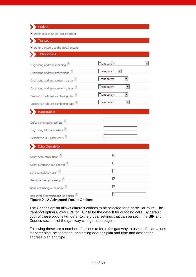
29 of 60
Figure 2-12 Advanced Route Options The Codecs option allows different codecs to be selected for a particular route. The transport option allows UDP or TCP to be the default for outgoing calls. By default both of these options will defer to the global settings that can be set in the SIP and Codecs sections of the gateway configuration pages. Following these are a number of options to force the gateway to use particular values for screening, presentation, originating address plan and type and destination address plan and type.
30 of 60
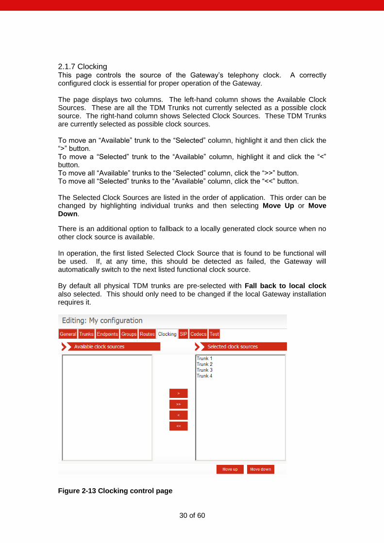
2.1.7 Clocking This page controls the source of the Gateway‟s telephony clock. A correctly configured clock is essential for proper operation of the Gateway. The page displays two columns. The left-hand column shows the Available Clock Sources. These are all the TDM Trunks not currently selected as a possible clock source. The right-hand column shows Selected Clock Sources. These TDM Trunks are currently selected as possible clock sources. To move an “Available” trunk to the “Selected” column, highlight it and then click the “>” button. To move a “Selected” trunk to the “Available” column, highlight it and click the “<” button. To move all “Available” trunks to the “Selected” column, click the “>>” button. To move all “Selected” trunks to the “Available” column, click the “<<” button. The Selected Clock Sources are listed in the order of application. This order can be changed by highlighting individual trunks and then selecting Move Up or Move Down.
There is an additional option to fallback to a locally generated clock source when no other clock source is available. In operation, the first listed Selected Clock Source that is found to be functional will be used. If, at any time, this should be detected as failed, the Gateway will automatically switch to the next listed functional clock source. By default all physical TDM trunks are pre-selected with Fall back to local clock also selected. This should only need to be changed if the local Gateway installation requires it.
Figure 2-13 Clocking control page
31 of 60
2.1.8 SIP This page configures SIP telephony settings. SIP transport for outgoing calls can be either UDP or TCP as required for the user‟s network. DTMF over IP send method: When the RFC2833 encoded RTP option is enabled DTMF tones will be encoded using the RFC2833 codec. When the option to use current codec is selected the tone will be sent in band. Other options are to send the tone in SIP Info messages as SIP Info dtmf or SIP Info dtmf-relay. For SIP Info DTMF type each DTMF tone is stripped from the audio stream and sent as a SIP INFO application/dtmf message. The body of each SIP INFO message indicates the dialled DTMF digit. For dtmf-relay type each DTMF tone is stripped from the audio stream and sent as a SIP INFO application/dtmf-relay message. The body of each SIP INFO message indicates the dialled DTMF digit and its duration. Tone duration of regenerated DTMF: This option allow the specification of the duration of DTMF tones, regenerated in response to SIP INFO messages of application/dtmf mime type. Interdigit duration of regenerated DTMF: This option allows the specification of the duration of silence in between DTMF tones, regenerated in response to SIP INFO messages. Enable comfort noise: By default comfort noise generation is on. In some circumstances this can cause problems so this option is to turn it off. Enable 183 provisional Responses: This option allows the sending of 183 provisional responses. Enable Discontinuous Transmission (DTX): With this enabled the ApplianX will not send packets when there is silence. Enable Packet Loss Concealment (PLC): With this set the ApplianX will attempt to conceal gaps in the audio. Enable RTCP: This option is to enable the sending of RTCP packets. Use 'sendonly' for Hold: The SDP attribute is set to “a=sendonly” to indicate a hold. Use 'inactive' for Hold: The SDP attribute is set to “a= inactive” to indicate a hold. Use 'recvonly' for Hold: The SDP attribute is set to “a= recvonly” to indicate a hold. Use SRTP on: This option controls how the ApplianX applies SRTP. By default SRTP is turned off. You can opt to enable SRTP on all outgoing TLS calls or all calls regardless of transport. (This is an option of some gateways) Require SRTP on incoming calls: When this option is enabled, the ApplianX will reject incoming calls that do not specify SRTP in their SDP. (This is an option of some gateways)
32 of 60
For incoming SIP calls, the SIP listening ports can be changed if required from the default of 5060 (for TCP and UDP) and 5061 (for TLS). In addition, by default, the SIP service will listen on both UDP and TCP ports for incoming calls. If either of these is not required, enter 0 (zero) to disable the port. NOTE: If both ports are set to 0 (zero), the Gateway will be unable to make or receive SIP calls. Endpoint Monitoring is enabled on a per-endpoint basis. You can control the interval between polling attempts with the Timeout option. Call diversion enabled: When enabled, the ApplianX will process diversion information for all SIP calls. History-Info Message Preferred: When enabled, the ApplianX will use „History-Info‟ headers to convey diversion information. When disabled, „diversion‟ headers will be used. Route redirect address: When enabled, the DivertTo address (Received in Redirect (3xx) messages) will be conveyed to the routing call leg. When disabled, the ApplianX will automatically respond to the 3xx message by making a new SIP call to the DivertTo address. Exchange transfer information: Exchange Route Optimisation/Path Replacement information: Following a call transfer involving a SIP endpoint, it is possible that two TDM endpoints may be connected over a SIP call leg where the gateway has called itself. To support subsequent transfers or for DPNSS Route Optimisation or QSIG Path Replacement, the gateway will send itself custom SIP INFO messages. In the unlikely event that this causes problems, either of these features can be disabled here. CBWF/CBWNU Enabled: When enabled, this option allows CallBackWhenFree / CallBackWhenNextUsed supplementary service information to be conveyed over SIP to another ApplianX.
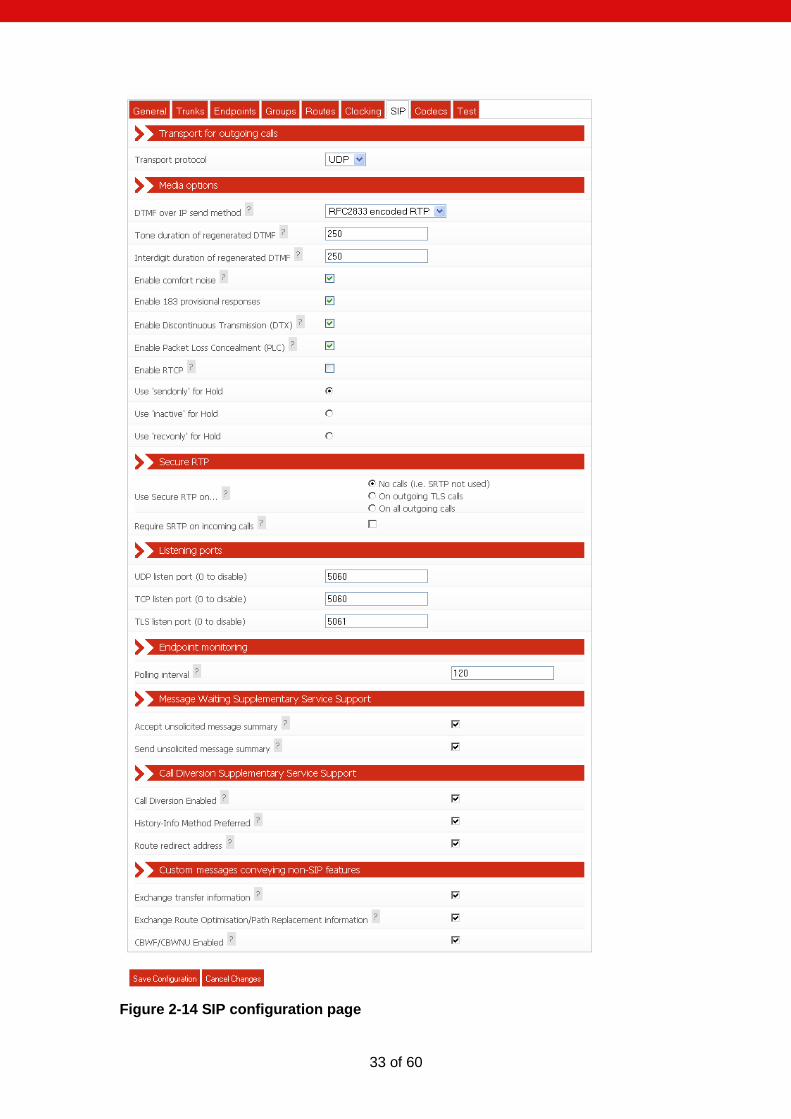
33 of 60
Figure 2-14 SIP configuration page
34 of 60
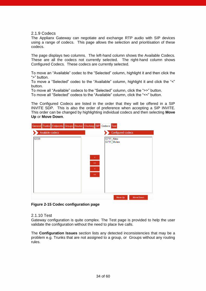
2.1.9 Codecs The Applianx Gateway can negotiate and exchange RTP audio with SIP devices using a range of codecs. This page allows the selection and prioritisation of these codecs. The page displays two columns. The left-hand column shows the Available Codecs. These are all the codecs not currently selected. The right-hand column shows Configured Codecs. These codecs are currently selected. To move an “Available” codec to the “Selected” column, highlight it and then click the “>” button. To move a “Selected” codec to the “Available” column, highlight it and click the “<” button. To move all “Available” codecs to the “Selected” column, click the “>>” button. To move all “Selected” codecs to the “Available” column, click the “<<” button. The Configured Codecs are listed in the order that they will be offered in a SIP INVITE SDP. This is also the order of preference when accepting a SIP INVITE. This order can be changed by highlighting individual codecs and then selecting Move Up or Move Down.
Figure 2-15 Codec configuration page
2.1.10 Test Gateway configuration is quite complex. The Test page is provided to help the user validate the configuration without the need to place live calls. The Configuration Issues section lists any detected inconsistencies that may be a problem e.g. Trunks that are not assigned to a group, or Groups without any routing rules.
35 of 60
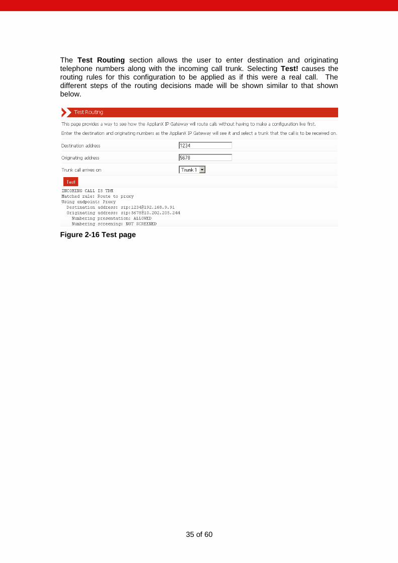
The Test Routing section allows the user to enter destination and originating telephone numbers along with the incoming call trunk. Selecting Test! causes the routing rules for this configuration to be applied as if this were a real call. The different steps of the routing decisions made will be shown similar to that shown below.
Figure 2-16 Test page
36 of 60
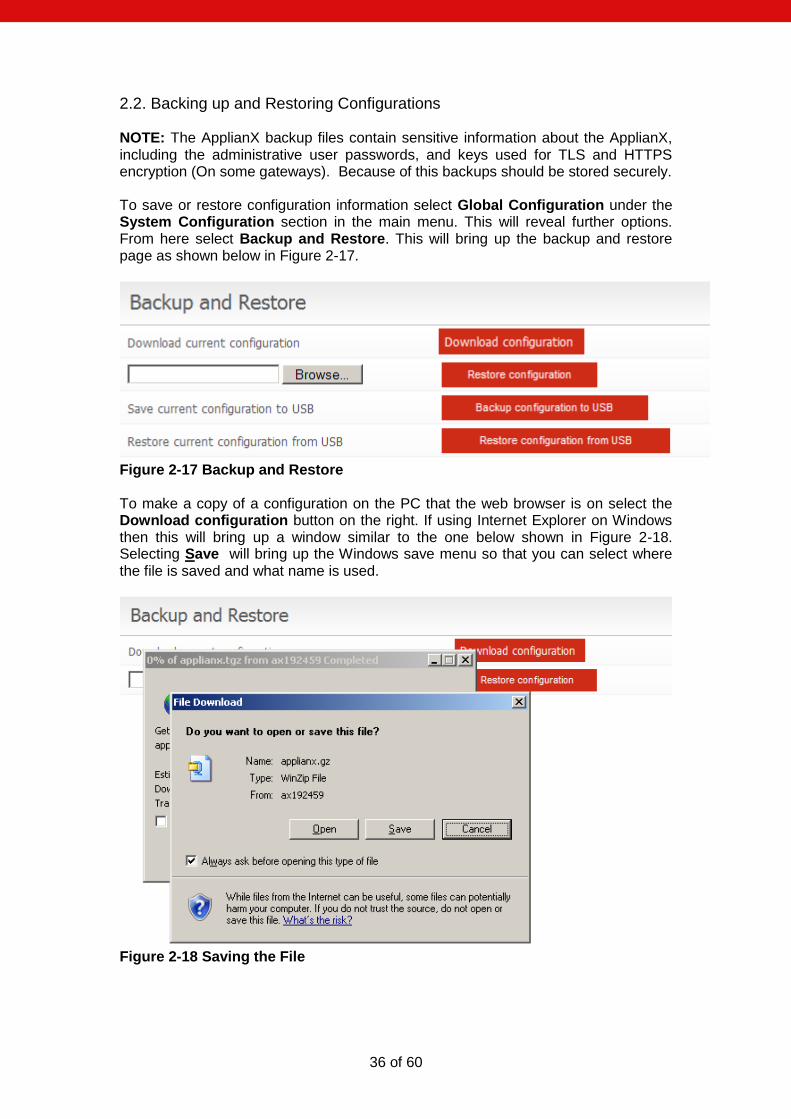
2.2. Backing up and Restoring Configurations NOTE: The ApplianX backup files contain sensitive information about the ApplianX, including the administrative user passwords, and keys used for TLS and HTTPS encryption (On some gateways). Because of this backups should be stored securely. To save or restore configuration information select Global Configuration under the System Configuration section in the main menu. This will reveal further options. From here select Backup and Restore. This will bring up the backup and restore page as shown below in Figure 2-17.
Figure 2-17 Backup and Restore To make a copy of a configuration on the PC that the web browser is on select the Download configuration button on the right. If using Internet Explorer on Windows then this will bring up a window similar to the one below shown in Figure 2-18. Selecting Save will bring up the Windows save menu so that you can select where the file is saved and what name is used.
Figure 2-18 Saving the File
37 of 60
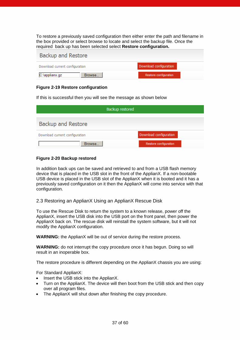
To restore a previously saved configuration then either enter the path and filename in the box provided or select browse to locate and select the backup file. Once the required back up has been selected select Restore configuration.
Figure 2-19 Restore configuration If this is successful then you will see the message as shown below
Figure 2-20 Backup restored In addition back ups can be saved and retrieved to and from a USB flash memory device that is placed in the USB slot in the front of the ApplianX. If a non-bootable USB device is placed in the USB slot of the ApplianX when it is booted and it has a previously saved configuration on it then the ApplianX will come into service with that configuration.
2.3 Restoring an ApplianX Using an ApplianX Rescue Disk To use the Rescue Disk to return the system to a known release, power off the ApplianX, insert the USB disk into the USB port on the front panel, then power the ApplianX back on. The rescue disk will reinstall the system software, but it will not modify the ApplianX configuration. WARNING: the ApplianX will be out of service during the restore process. WARNING: do not interrupt the copy procedure once it has begun. Doing so will result in an inoperable box. The restore procedure is different depending on the ApplianX chassis you are using: For Standard ApplianX:
Insert the USB stick into the ApplianX.
Turn on the ApplianX. The device will then boot from the USB stick and then copy over all program files.
The ApplianX will shut down after finishing the copy procedure.

38 of 60
Important: remember to remove the USB stick after the copy operation has finished. Switching on the ApplianX again with the stick inserted will result in the Rescue Disk backup procedure starting again.
The ApplianX will update various system configuration files and will shut down again. After this, the ApplianX can be restarted and will be in a state ready for use.
For Compact ApplianX:
Insert the USB stick into the ApplianX.
Power on the ApplianX.
Watch the LED boot sequence carefully. When the LED to the right most of the panel (labelled “Error”) is highlighted, briefly press and release the Reset button (see note).
If you have pressed the reset button correctly, all LEDs will go off, and then flash on/off a few times. If you do not get this flash sequence then start the restore procedure again.
The Rescue Disk will then start running after a couple of seconds.
After the procedure has finished, the ApplianX will reboot, refresh its system configuration files, then it will reboot into the restored system.
NOTE: Do not hold the reset button for more than about half a second – the ApplianX will reboot itself without restoring the software.
39 of 60
3.0 Additional Information 3.1 Routing Overview The routing of telephone calls forms the core function of the Gateway and is the most complex area to configure. A caller dials a number that causes a call to arrive at the gateway. The Gateway applies user-defined rules to the dialled number in order to identify the target user and how they can be contacted. The Gateway then makes an outbound call to this target user and connects the two calls together. This whole process is termed call routing. Some definitions:
Trunk – a physical connection capable of carrying many calls
Group – a user defined logical group of trunks or endpoints
Telephone number – a sequence of digits associated with a physical telephone, e.g. 01234567890
SIP user address – a sequence of characters in SIP URL format associated with a SIP client user, e.g. [email protected]
Originating Address – the telephone number or SIP address of the caller
Destination Address – the telephone number or SIP address of the callee
Route – a set of information that specifies :
a pattern to match against a call destination address
a rule that allows changes to the originating address
a rule that allows changes to the destination address
the type of routing to perform (to a Trunk Group or a User)
a trunk group on which to make outgoing calls
Some important things to know:
Each Group must have at least one rule associated with it
Each Group can only contain Trunks of one type, either SIP or TDM
40 of 60
3.2 X.509 Certificates For those gateways that support HTTPS, SIPS and SRTP then X.509 certificates are used. This section provides some information about the use of X.509 certificates for both HTTPS and SIPS. This is not a primer on X.509 or the use of certificates. Instructions are provided (below) for creating a local Certificate Authority and issuing certificates using OpenSSL. Your organisation may have another procedure for obtaining certificates – if so you should use that. For the purposes of HTTPS and SIP over TLS each device needs an X.509 certificate and a private key. The ApplianX uses two such chains of trust certificates – one for HTTPS and one for TLS. Out of the box the ApplianX provides a default HTTPS chain of trust but does not provide one for SIP over TLS. The ApplianX uses X.509 certificates in base64-encoded Privacy Enhanced Mail ("PEM") format. The chains of trust for HTTPS and SIP over TLS are formed by concatenating the private key and the certificate together into a single text file. The ApplianX will check the validity of its certificates nightly and will warn of expired or nearly expired certificates via SNMP. The ApplianX will warn ten days prior to the expiry of a TLS or HTTPS certificate. Certificate problems are also indicated on the Overview page. The check for validity is also re-run whenever a change is made to the HTTPS or TLS configuration and this will also lead to the generation of SNMP traps.
41 of 60
3.3 Creating X.509 certificates using OpenSSL
These instructions assume you have downloaded OpenSSL and PERL for your platform. Most Unix-like operating systems (including OS X) will include both PERL and OpenSSL or make it available from their software repositories. For Windows you can obtain OpenSSL by following links on this page: http://openssl.org/related/binaries.html. PERL can be obtained from: www.perl.com. NOTE: Your organisation may have a set procedure for obtaining certificates. If so, you should follow that procedure rather than these instructions. First, you need a Certificate Authority which will issue certificates for your devices. You only need to create this once and you should keep a backup of it. There are a number of ways of doing this using OpenSSL to issue certificates, but for this we will use the CA.pl PERL script that is provided in the OpenSSL package. On a Unix-like system this could be in /usr/lib/ssl/misc/ or /usr/share/ssl/misc/CA. On Windows it will be in the bin directory of the OpenSSL distribution. In the following instruction, replace the path/to/CA.pl with the appropriate path for your system. Unless otherwise noted, all commands will work on Windows and Unix-like operating systems. > represents the command line prompt for your operating system. Commands for you to type are in italics. Make sure that both the perl and openssl executables are in your path. CA.pl will create a certificate database in your current directory so first you need to create a directory to work in. > mkdir certificates
> cd certificates
Create a new Certificate Authority: > perl /path/to/CA.pl -newca
CA certificate filename (or enter to create) [ENTER]
Making CA certificate ...
Loading 'screen' into random state - done
Generating a 1024 bit RSA private key
....................................................................++++++
.++++++
writing new private key to './demoCA/private/cakey.pem'
Enter PEM pass phrase:
Here you need to enter a secure pass phrase for your
Certificate Authority. This is intended to keep your CA
secure and make it harder for somebody to issue certificates.
You need to remember this phrase as you will need it to issue
certificates.
Verifying - Enter PEM pass phrase:
Enter the same phrase again.
You will be prompted for further information about your CA. You can optionally enter a number of things to provide information about your certificate.
42 of 60
-----
You are about to be asked to enter information that will be incorporated
into your certificate request.
What you are about to enter is what is called a Distinguished Name or a DN.
There are quite a few fields but you can leave some blank
For some fields there will be a default value,
If you enter '.', the field will be left blank.
-----
Country Name (2 letter code) [AU]:UK
State or Province Name (full name) [Some-State]:Bucks
Locality Name (eg, city) []:Milton Keynes
Organization Name (eg, company) [Internet Widgits Pty Ltd]:Wainwright's
Fruit Emporium
Organizational Unit Name (eg, section) []:Kiwi Division
Common Name (eg, YOUR name) []:Wayne Wainwright
Email Address []:[email protected]
Please enter the following 'extra' attributes
to be sent with your certificate request
A challenge password []:
An optional company name []:
Using configuration from C:\OpenSSL\bin\openssl.cnf
Loading 'screen' into random state – done
That's all of the information you need to give. The tool will
now prompt you for the Certificate Authority pass phrase so it
can print out information about the certificate:
Enter pass phrase for ./demoCA/private/cakey.pem:
Check that the request matches the signature
Signature ok
Certificate Details:
Serial Number:
82:ac:ff:1e:be:8c:16:32
Validity
Not Before: Nov 13 12:46:21 2009 GMT
Not After : Nov 12 12:46:21 2012 GMT
Subject:
countryName = UK
stateOrProvinceName = Bucks
organizationName = Wainwright's Fruit Emporium
organizationalUnitName = Kiwi Division
commonName = Wayne Wainwright
emailAddress = [email protected]
X509v3 extensions:
X509v3 Subject Key Identifier:
6D:8D:85:42:CA:91:B6:FB:F9:CB:53:CE:10:62:15:B5:45:D3:B7:7B
X509v3 Authority Key Identifier:
keyid:6D:8D:85:42:CA:91:B6:FB:F9:CB:53:CE:10:62:15:B5:45:D3:B7:7
B
DirName:/C=UK/ST=Bucks/O=Wainwright's Fruit Emporium/OU=Kiwi
Div
ision/CN=Wayne Wainwright/[email protected]
serial:82:AC:FF:1E:BE:8C:16:32
X509v3 Basic Constraints:
CA:TRUE
Certificate is to be certified until Nov 12 12:46:21 2012 GMT (1095 days)
Write out database with 1 new entries
Data Base Updated
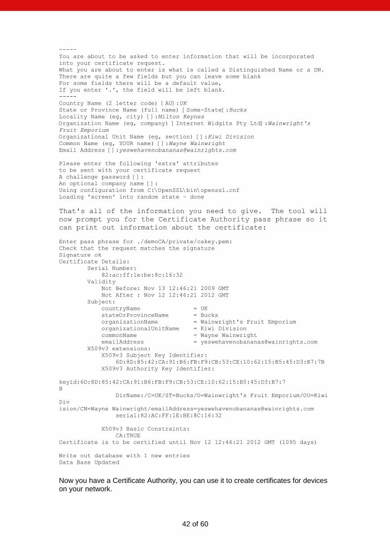
Now you have a Certificate Authority, you can use it to create certificates for devices on your network.
43 of 60
Creating a certificate is a two step process. Firstly you need to create a certificate request. As part of this process a private key is created for the device. Once the request has been generated you need to sign the certificate with the Certificate Authority's key. > perl /path/to/CA.pl -newreq
Loading 'screen' into random state - done
Generating a 1024 bit RSA private key
..............................++++++
...................++++++
writing new private key to 'newkey.pem'
You will be prompted for a pass phrase for the private key. You can remove the pass phrase later. Enter PEM pass phrase:
Verifying - Enter PEM pass phrase:
Next you will be prompted for information about the device that the certificate is for. The important field is the Common Name field which you should set to the DNS name or IP address of the device in question. -----
You are about to be asked to enter information that will be incorporated
into your certificate request.
What you are about to enter is what is called a Distinguished Name or a DN.
There are quite a few fields but you can leave some blank
For some fields there will be a default value,
If you enter '.', the field will be left blank.
-----
Country Name (2 letter code) [AU]:UK
State or Province Name (full name) [Some-State]:Bucks
Locality Name (eg, city) []:Milton Keynes
Organization Name (eg, company) [Internet Widgits Pty Ltd]:Wainright's Fruit
Emporium
Organizational Unit Name (eg, section) []:Kiwi Division
Common Name (eg, YOUR name) []:192.168.1.1
Email Address []:
Please enter the following 'extra' attributes
to be sent with your certificate request
A challenge password []:
An optional company name []:
Request is in newreq.pem, private key is in newkey.pem
Now you need to sign the request to create the certificate: > perl /path/to/CA.pl -sign
Using configuration from C:\OpenSSL\bin\openssl.cnf
Loading 'screen' into random state – done
Now the tool will prompt you for the pass phrase for the Certificate Authority. It will then print information about the certificate and prompt you to check that you want to sign the certificate. Enter pass phrase for ./demoCA/private/cakey.pem:
Check that the request matches the signature
Signature ok
Certificate Details:
Serial Number:
82:ac:ff:1e:be:8c:16:33
Validity
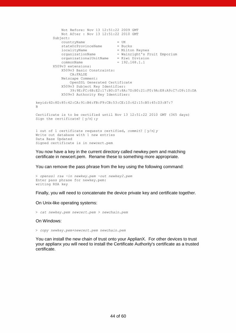
44 of 60
Not Before: Nov 13 12:51:22 2009 GMT
Not After : Nov 13 12:51:22 2010 GMT
Subject:
countryName = UK
stateOrProvinceName = Bucks
localityName = Milton Keynes
organizationName = Wainright's Fruit Emporium
organizationalUnitName = Kiwi Division
commonName = 192.168.1.1
X509v3 extensions:
X509v3 Basic Constraints:
CA:FALSE
Netscape Comment:
OpenSSL Generated Certificate
X509v3 Subject Key Identifier:
39:9E:FC:6B:E2:17:B0:D7:8A:7D:B0:21:F0:9A:E8:A9:C7:D9:10:DA
X509v3 Authority Key Identifier:
keyid:6D:8D:85:42:CA:91:B6:FB:F9:CB:53:CE:10:62:15:B5:45:D3:B7:7
B
Certificate is to be certified until Nov 13 12:51:22 2010 GMT (365 days)
Sign the certificate? [y/n]:y
1 out of 1 certificate requests certified, commit? [y/n]y
Write out database with 1 new entries
Data Base Updated
Signed certificate is in newcert.pem
You now have a key in the current directory called newkey.pem and matching certificate in newcert.pem. Rename these to something more appropriate. You can remove the pass phrase from the key using the following command: > openssl rsa -in newkey.pem -out newkey2.pem
Enter pass phrase for newkey.pem:
writing RSA key
Finally, you will need to concatenate the device private key and certificate together. On Unix-like operating systems: > cat newkey.pem newcert.pem > newchain.pem
On Windows: > copy newkey.pem+newcert.pem newchain.pem
You can install the new chain of trust onto your ApplianX. For other devices to trust your applianx you will need to install the Certificate Authority's certificate as a trusted certificate.
45 of 60
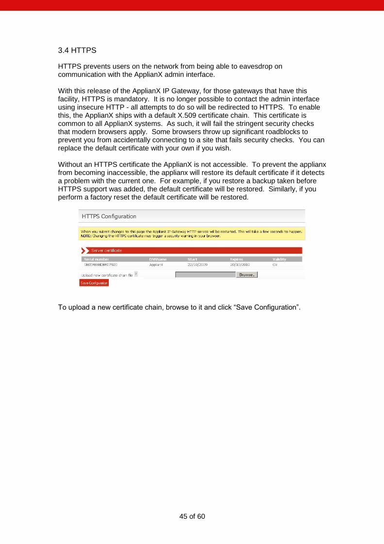
3.4 HTTPS
HTTPS prevents users on the network from being able to eavesdrop on communication with the ApplianX admin interface. With this release of the ApplianX IP Gateway, for those gateways that have this facility, HTTPS is mandatory. It is no longer possible to contact the admin interface using insecure HTTP - all attempts to do so will be redirected to HTTPS. To enable this, the ApplianX ships with a default X.509 certificate chain. This certificate is common to all ApplianX systems. As such, it will fail the stringent security checks that modern browsers apply. Some browsers throw up significant roadblocks to prevent you from accidentally connecting to a site that fails security checks. You can replace the default certificate with your own if you wish. Without an HTTPS certificate the ApplianX is not accessible. To prevent the applianx from becoming inaccessible, the applianx will restore its default certificate if it detects a problem with the current one. For example, if you restore a backup taken before HTTPS support was added, the default certificate will be restored. Similarly, if you perform a factory reset the default certificate will be restored.
To upload a new certificate chain, browse to it and click “Save Configuration”.
46 of 60
3.5 Secure SIP over TLS
SIP over TLS provides two abilities:
At its basic level TLS provides a level of privacy, preventing a packet sniffer from viewing the contents of the protocol exchange between parties.
With all of the security options turned on TLS provides confidence that both parties in a call are who they say they are.
Out of the box the ApplianX has TLS disabled and contains no certificates and has no chain of trust. It is up to the user to generate a chain of trust (see instructions). NOTE: Not all gateways have SIPS and SRTP capabilities. NOTE: X.509 certificates contain timestamps that are used to determine their validity. It is important that the clock on the ApplianX is accurate – NTP is the recommended method to achieve this. NOTE: TLS protects the SIP session only, to prevent eavesdropping of conversation both TLS and SRTP are required. NOTE: TLS does not prevent a packet sniffer such as Wireshark from determining the parties involved in a conversation. Sometimes this information alone is useful to an interloper. NOTE: TLS is no substitute for paying attention to network security. In particular the peer validation checks can be subverted if an attacker can interfere with the normal operation of DNS on your network (see for example the tools "Cain and Abel" which are just an Internet search away). NOTE: You shouldn't try to make a separate connection for each call - this will put unnecessary load on both endpoints as establishing a TLS connection is very CPU intensive. The ApplianX will always attempt to re-use existing TLS connections. NOTE: In the current IP Gateway release it can be difficult to determine the cause for TLS call failure. In particular it is impossible to distinguish between attempting to connect to a non-existent host, a host that doesn't support TLS, or a host that presents an invalid certificate. Packet sniffing using a tool such as Wireshark can shed some light on this.
47 of 60
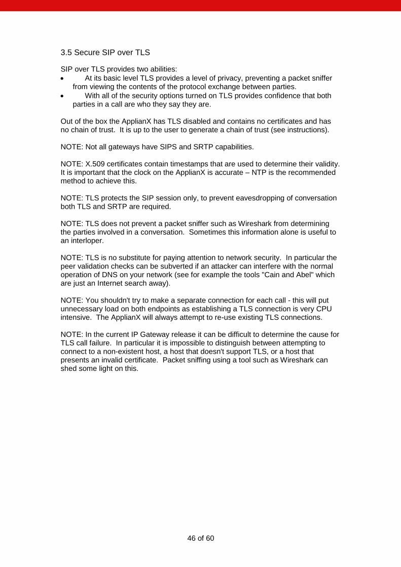
Changing the following settings will require a reboot of the ApplianX: Use TLS is the global setting that enables or disables TLS. When this option is disabled, the ApplianX will not listen for incoming TLS calls and will not be able to make outgoing TLS calls. Require Peer Certificate causes the ApplianX to request the remote party's certificate during session negotiation. If the remote party doesn't have a certificate, the negotiation will fail. Maximum chain length controls the number of certificates in the remote party's certificate chain that the ApplianX will examine when looking for the signature of a trusted party. This is in addition to the host's own certificate (i.e. if you set the chain length to 1 then a maximum of TWO certificates will be examined). Setting this to 0 will allow the ApplianX to examine all certificates in the chain. This setting has a number of implications. Firstly, examining more certificates simply takes longer. A malicious party could present very long certificate chain, tying up the ApplianX for a long period of time. Secondly, each additional certificate in a chain of trust increases the opportunities for an attacker to get hold of a legitimate certificate (e.g. through compromising a host holding a CA and generating a new certificate, through social engineering, etc.). Typically you should set this to the smallest number you can. The Verify remote host address option adds an additional check to the TLS handshake. This check will compare the host name in the certificate against the address of the remote host. If the two do not match then the handshake will fail. For maximum security, all options should be turned on, with the Maximum chain length set to the smallest value that will work for your organisation. The ApplianX should be given its own certificate tied to its IP address/DNS name. You should add
48 of 60
the certificates for the Certificate Authorities that you have used to issue certificates to other devices on your network. Additionally you can provide Diffie-Hellman parameters to increase the security of the TLS handshake process. The following configuration options do not require a reboot: Sever certificate: This is the certificate chain that the ApplianX should present to other devices on the network. You can upload a single chain of trust which should be in base64-encoded Privacy Enhanced Mail (PEM) format and should consist of the private key for the ApplianX plus the certificate of the ApplianX plus any additional certificates in the chain. For example: -----BEGIN RSA PRIVATE KEY-----
MIICXgIBAAKBgQC7a0ZYUQX0RYI9UZatoZsmpmkBopi7n2s5cDRcxgzlTm7voUC4
eVkEGyyEZ3FfUhdjRZXazhkR1qrjh7PHBbEnz8uAEI8bEiZIRipB+1y/r8Sn75XE
20Z3gO82zergfWnwQ2oRM77fUKJE3jAfth/7x9vKK1A0FDdhZCxfceVfQQIDAQAB
AoGBAJL+YzDXc20Pq0N+n0hVTMO2lvsiVNorAcUN/POanfinWJj3hzRocGmpCnRa
UXAqiY9hv1Pae40jKerEvzrkevldKbOoBr75xYKNf3HXppcSC2z4qkzCu6dY4G3U
TbdbdvBduoeqqERuNZZFT4uV+zpJW7UAQ5ZhT3vL1H9c0XPlAkEA+TaP0+cB/WMJ
+EsORI5SYVNs/QKB/D0Y7z+OmfrjDxUluK+LEkPMDdd7LX4/uDtRAFwhSq2lCNnj
vx+g/oCvdwJBAMCF50IwGqHmspPjFIBLDyDCWMPaMM1QaP2S4GI30dYSjVQxdwyO
6C17ED0f29SZ7JfOUa9XL7ql04fuwC/2xQcCQHwTezZgPDBgv9T74WWmikNkms25
Euh3rtNnDGODcsrOl5JE6/OzB4QYtX4n7ieWeLS6KeUZYSJwASDl6Wzsuu8CQQCA
DRAiH+i24sDISHNsWYA4Y8uyiL+I8ADFGBoSedohrrk91KDAQ5T+GypT3YrTv4Vz
+xCttSnT1VP6x7wgqtulAkEA5sfdjuII4ZyjgNUER82bvtreCuNzj1qw7Q7+sBl8
9FlALfRXTIgJjUVgDBaVEuhQfIFHspOtYmP1TQAoMq49Vw==
-----END RSA PRIVATE KEY-----
-----BEGIN CERTIFICATE-----
MIICYTCCAcoCCQCeBfuL3v15ITANBgkqhkiG9w0BAQUFADB6MRMwEQYDVQQKEwpB
Y3VsYWIgUGxjMREwDwYDVQQLEwhBcHBsaWFuWDETMBEGA1UEBxMKTW91bnQgRmFy
bTEWMBQGA1UECBMNTWlsdG9uIEtleW5lczELMAkGA1UEBhMCVUsxFjAUBgNVBAMT
DUFwcGxpYW5YIFRlYW0wHhcNMDkxMDIzMTAyMTIwWhcNMDkxMDI0MTAyMTIwWjBw
MRMwEQYDVQQKEwpBY3VsYWIgUGxjMREwDwYDVQQLEwhBcHBsaWFuWDETMBEGA1UE
BxMKTW91bnQgRmFybTEWMBQGA1UECBMNTWlsdG9uIEtleW5lczELMAkGA1UEBhMC
VUsxDDAKBgNVBAMTA3JvYjCBnzANBgkqhkiG9w0BAQEFAAOBjQAwgYkCgYEAu2tG
WFEF9EWCPVGWraGbJqZpAaKYu59rOXA0XMYM5U5u76FAuHlZBBsshGdxX1IXY0WV
2s4ZEdaq44ezxwWxJ8/LgBCPGxImSEYqQftcv6/Ep++VxNtGd4DvNs3q4H1p8ENq
ETO+31CiRN4wH7Yf+8fbyitQNBQ3YWQsX3HlX0ECAwEAATANBgkqhkiG9w0BAQUF
AAOBgQCQo+DvcTkMucmPx7CWo/R3KiBEsSbArRKPG2OYqH5E4t4tsqMExOaqg/ts
CwtGlnWLrt/NJidBceG43d/tukLNbNF4hDLFSb01C0CgJoLRZT2bFmtn3C7T6MCg
4J0ujOIhKcdixuDxrQcdVmxzQE+8IPOsawx0pijEL4c8z2i4Iw==
-----END CERTIFICATE-----
If the key has a pass phrase then enter it into the Private key password field. Trusted certificates: These are the certificates that the ApplianX will use to validate the chain of trust presented by each remote host. If multiple Certificate Authorities are in use on your network you can upload multiple certificates. You must click on the “Submit changes” button to upload each certificate individually. Diffie-Hellman parameters: These are used during the TLS handshake process to improve security. You can upload 512-bit and 1024-bit parameters. These need to be Base64-encoded
49 of 60
3.6 Software Updates From the 2.1.0 release onwards, the ApplianX uses a whole-image upgrade method. This overwrites the ApplianX software with a different version, allowing upgrade or downgrade to a known version. The user configuration is unaffected by the version change. Update images can be applied either from a USB disk or over a network by an HTTP server. A simple HTTP server is provided by the ax-img-tool utility. A number of caveats apply:
You must not interrupt the upgrade process.
Downgrade to older versions than the 2.1.0 release is not supported.
An older version of the ApplianX will not necessarily be able to fully use a configuration generated by a newer version. It is recommended that you take a configuration backup prior to upgrade and use this backup if you should need to downgrade for any reason.
Getting update images Update images are available from http://archive.applianx.com.
Getting ax-img-tool You can download the latest version of this tool from http://archive.applianx.com.
Validating update images The ApplianX will validate images prior to applying them. This validation helps to ensure that the upgrade is going to succeed. Additionally, you can manually validate an image using the ax-img-tool utility. You can do this for extra confidence when you have downloaded the image over an unreliable connection. Validation can be performed from the command line using the ax-img-tool utility:
c:\Program Files\ApplianX\> ax-img-tool -i name-of-image
Will display:
ax-img-tool version 1.0
Copyright (C) 2010 Aculab
Image is IPGATEWAY version 2.0.5 (build 52) for a Standard ApplianX
Image was generated on: Tue Apr 13 16:52:38 BST 2010
Verifying checksum (CTRL-C to cancel)....OK
Image is good
If the tool reports that the image checksum is bad, don‟t attempt to use that image to upgrade your ApplianX.
50 of 60
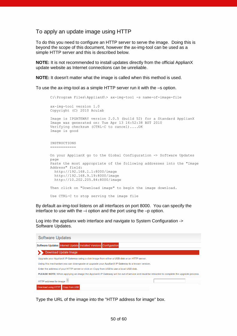
To apply an update image using HTTP To do this you need to configure an HTTP server to serve the image. Doing this is beyond the scope of this document, however the ax-img-tool can be used as a simple HTTP server and this is described below. NOTE: It is not recommended to install updates directly from the official ApplianX update website as Internet connections can be unreliable. NOTE: It doesn't matter what the image is called when this method is used. To use the ax-img-tool as a simple HTTP server run it with the –s option.
C:\Program Files\ApplianX\> ax-img-tool -s name-of-image-file
ax-img-tool version 1.0
Copyright (C) 2010 Aculab
Image is IPGATEWAY version 2.0.5 (build 52) for a Standard ApplianX
Image was generated on: Tue Apr 13 16:52:38 BST 2010
Verifying checksum (CTRL-C to cancel)....OK
Image is good
INSTRUCTIONS
============
On your ApplianX go to the Global Configuration -> Software Updates
page
Paste the most appropriate of the following addresses into the "Image
Address" field:
http://192.168.1.1:8000/image
http://192.168.9.19:8000/image
http://10.202.205.84:8000/image
Then click on "Download image" to begin the image download.
Use CTRL-C to stop serving the image file
By default ax-img-tool listens on all interfaces on port 8000. You can specify the interface to use with the –i option and the port using the –p option. Log into the applianx web interface and navigate to System Configuration -> Software Updates.
Type the URL of the image into the "HTTP address for image" box.
51 of 60
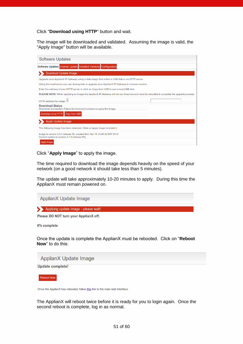
Click "Download using HTTP" button and wait. The image will be downloaded and validated. Assuming the image is valid, the "Apply Image" button will be available.
Click “Apply Image” to apply the image. The time required to download the image depends heavily on the speed of your network (on a good network it should take less than 5 minutes). The update will take approximately 10-20 minutes to apply. During this time the ApplianX must remain powered on.
Once the update is complete the ApplianX must be rebooted. Click on “Reboot Now” to do this:
The ApplianX will reboot twice before it is ready for you to login again. Once the second reboot is complete, log in as normal.
52 of 60
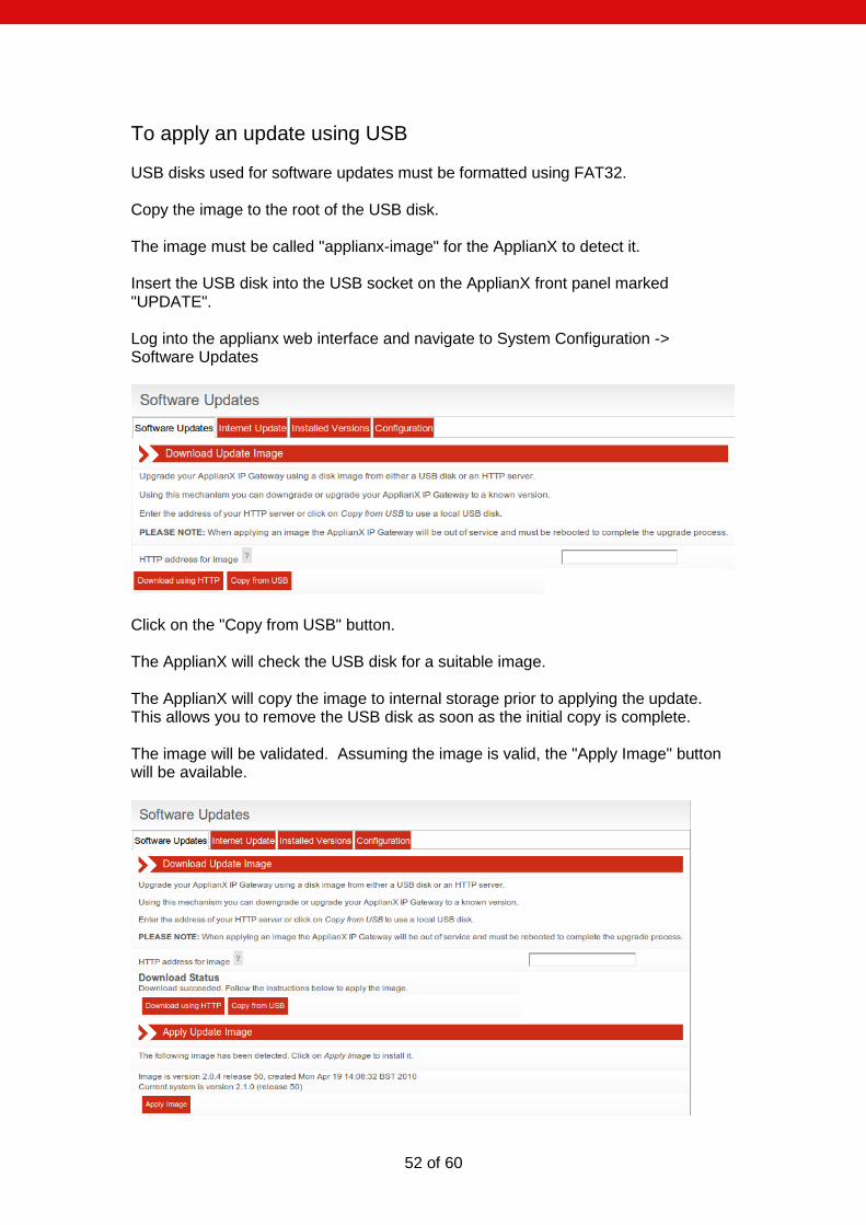
To apply an update using USB USB disks used for software updates must be formatted using FAT32. Copy the image to the root of the USB disk. The image must be called "applianx-image" for the ApplianX to detect it. Insert the USB disk into the USB socket on the ApplianX front panel marked "UPDATE". Log into the applianx web interface and navigate to System Configuration -> Software Updates
Click on the "Copy from USB" button. The ApplianX will check the USB disk for a suitable image. The ApplianX will copy the image to internal storage prior to applying the update. This allows you to remove the USB disk as soon as the initial copy is complete. The image will be validated. Assuming the image is valid, the "Apply Image" button will be available.
53 of 60
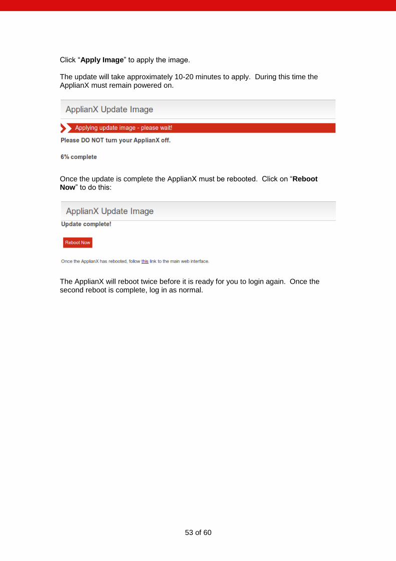
Click “Apply Image” to apply the image. The update will take approximately 10-20 minutes to apply. During this time the ApplianX must remain powered on.
Once the update is complete the ApplianX must be rebooted. Click on “Reboot Now” to do this:
The ApplianX will reboot twice before it is ready for you to login again. Once the second reboot is complete, log in as normal.
54 of 60
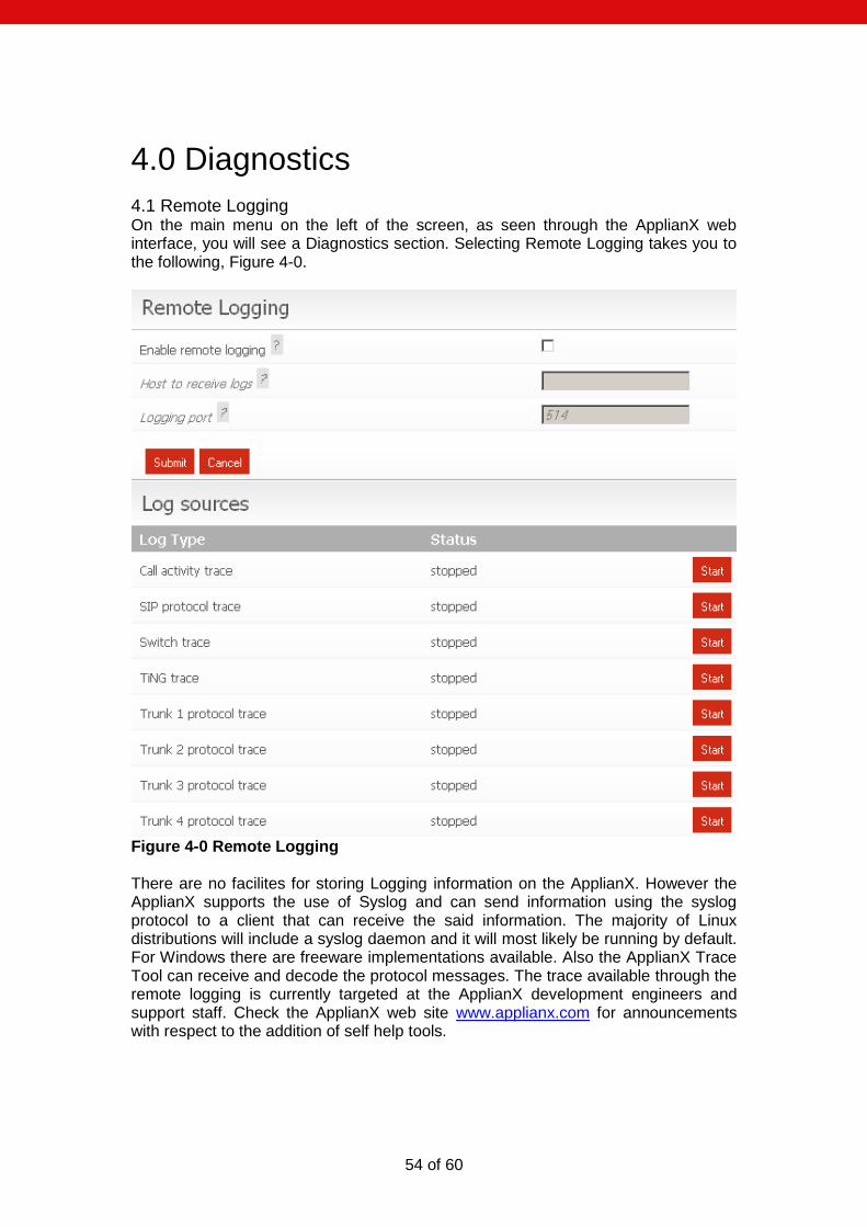
4.0 Diagnostics
4.1 Remote Logging On the main menu on the left of the screen, as seen through the ApplianX web interface, you will see a Diagnostics section. Selecting Remote Logging takes you to the following, Figure 4-0.
Figure 4-0 Remote Logging There are no facilites for storing Logging information on the ApplianX. However the ApplianX supports the use of Syslog and can send information using the syslog protocol to a client that can receive the said information. The majority of Linux distributions will include a syslog daemon and it will most likely be running by default. For Windows there are freeware implementations available. Also the ApplianX Trace Tool can receive and decode the protocol messages. The trace available through the remote logging is currently targeted at the ApplianX development engineers and support staff. Check the ApplianX web site www.applianx.com for announcements with respect to the addition of self help tools.
55 of 60
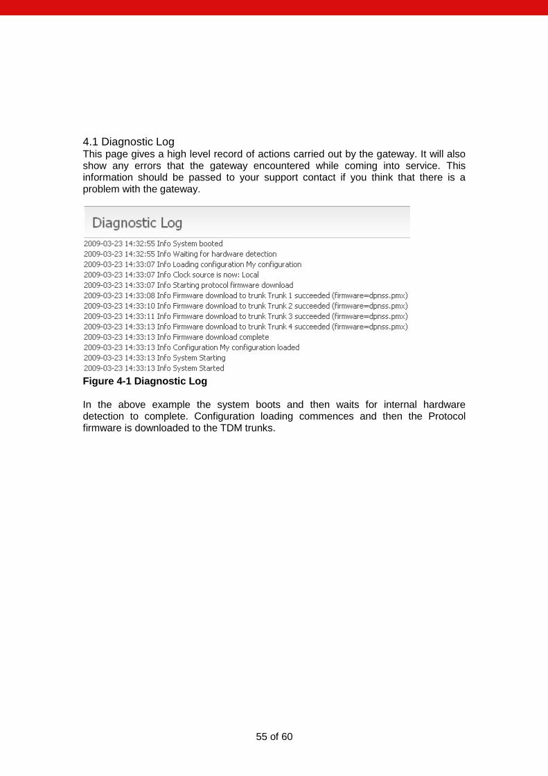
4.1 Diagnostic Log This page gives a high level record of actions carried out by the gateway. It will also show any errors that the gateway encountered while coming into service. This information should be passed to your support contact if you think that there is a problem with the gateway.
Figure 4-1 Diagnostic Log In the above example the system boots and then waits for internal hardware detection to complete. Configuration loading commences and then the Protocol firmware is downloaded to the TDM trunks.
56 of 60
5.0 Troubleshooting
5.1 Logging into the remote interface
5.1.1 I can‟t get access to the ApplianX Gateway Web Interface
Try using the ApplianX Search Tool on a Windows PC to detect the ApplianX and to obtain its IP address.
Try checking the cabling and then try to log in again. The PC and the ApplianX administration port must be connected directly together for initial setup.
On a Windows XP PC are you using Microsoft Explorer Version 6 or 7? If not try using one of these browsers. Note that version 7 is preferred.
Try connecting the network port of your PC directly to the ApplianX administration port.
Try accessing the web interface from an up to date Linux or MAC OS X PC using axnnnnnn.local address if you have one available. Did this work? If so you may have DNS/DHCP network issues. Move to using
static IP addresses
Try setting the IP of the admin port to a known static IP address using a USB flash memory stick as described in section 1.9.2.
5.1.2 I log on but the overview screen has errors at the top
Wait a couple of minutes and then refresh the screen. The web interface can start before the gateway, which means that until the gateway has started, the interface will report that it cannot talk to the gateway engine.
5.1.3 I get a warning saying that the gateway cannot.
This is normal when the unit has started or been rebooted or has had its IP settings changed. The elements that make up the gateway are just starting and establishing their communication paths.
5.2 Making Calls through the Gateway
5.2.1 I can‟t make a call from the TDM side of the Gateway to an IP client.
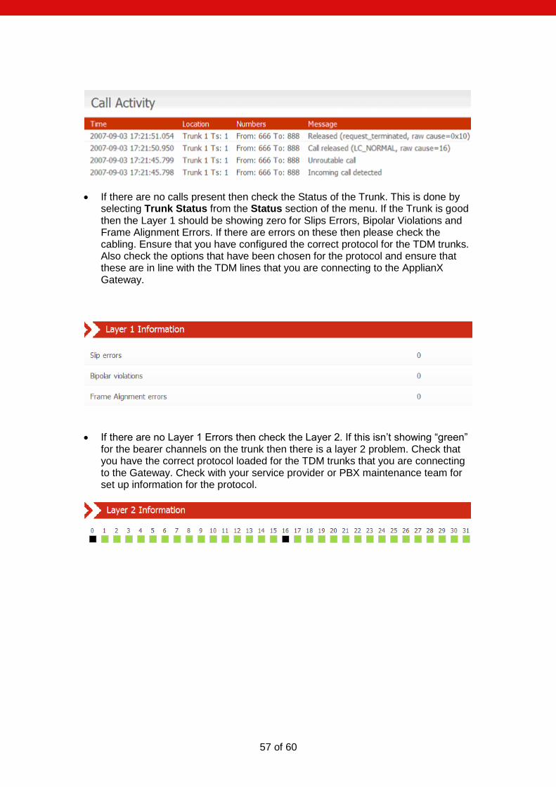
Check the Call Status Page by selecting “Calls” under the Status section on the menu on the left of the Administration web interface. Now make the call in from the TDM side of the gateway. Check the Call Activity at the bottom of the screen to see whether the Call was received by the gateway. In this case you can see that the Gateway did indeed receive the call but could not route it. You will need to check your routing rules so that the Gateway has the information it needs to route the calls. See section 2 of this User Guide.
57 of 60
If there are no calls present then check the Status of the Trunk. This is done by selecting Trunk Status from the Status section of the menu. If the Trunk is good then the Layer 1 should be showing zero for Slips Errors, Bipolar Violations and Frame Alignment Errors. If there are errors on these then please check the cabling. Ensure that you have configured the correct protocol for the TDM trunks. Also check the options that have been chosen for the protocol and ensure that these are in line with the TDM lines that you are connecting to the ApplianX Gateway.
If there are no Layer 1 Errors then check the Layer 2. If this isn‟t showing “green” for the bearer channels on the trunk then there is a layer 2 problem. Check that you have the correct protocol loaded for the TDM trunks that you are connecting to the Gateway. Check with your service provider or PBX maintenance team for set up information for the protocol.
58 of 60
5.3 Configuring the Gateway
5.3.1 I have made changes to the configuration but they don‟t seem to have any effect.
The Gateway does not allow you to edit a configuration that is in use. For this reason you can copy a configuration and edit this. Before these changes can take effect you must select that the gateway use this edited configuration. This is done by selecting the “Use” button by the side of the edited configuration on Edit Configurations page.
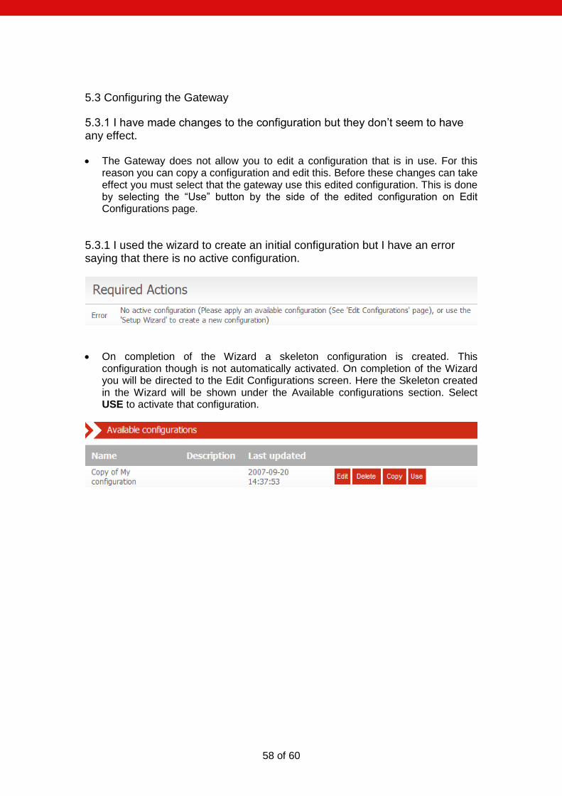
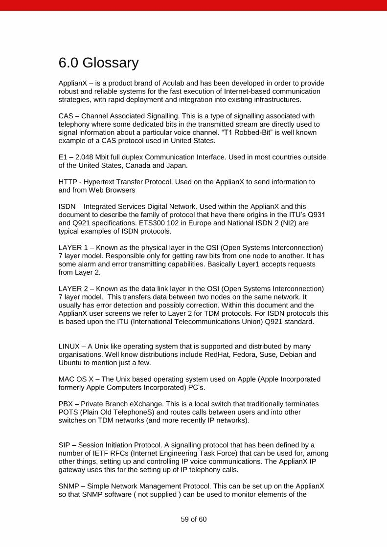
5.3.1 I used the wizard to create an initial configuration but I have an error saying that there is no active configuration.
On completion of the Wizard a skeleton configuration is created. This configuration though is not automatically activated. On completion of the Wizard you will be directed to the Edit Configurations screen. Here the Skeleton created in the Wizard will be shown under the Available configurations section. Select USE to activate that configuration.
59 of 60
6.0 Glossary ApplianX – is a product brand of Aculab and has been developed in order to provide robust and reliable systems for the fast execution of Internet-based communication strategies, with rapid deployment and integration into existing infrastructures. CAS – Channel Associated Signalling. This is a type of signalling associated with telephony where some dedicated bits in the transmitted stream are directly used to signal information about a particular voice channel. “T1 Robbed-Bit” is well known example of a CAS protocol used in United States. E1 – 2.048 Mbit full duplex Communication Interface. Used in most countries outside of the United States, Canada and Japan. HTTP - Hypertext Transfer Protocol. Used on the ApplianX to send information to and from Web Browsers ISDN – Integrated Services Digital Network. Used within the ApplianX and this document to describe the family of protocol that have there origins in the ITU‟s Q931 and Q921 specifications. ETS300 102 in Europe and National ISDN 2 (NI2) are typical examples of ISDN protocols. LAYER 1 – Known as the physical layer in the OSI (Open Systems Interconnection) 7 layer model. Responsible only for getting raw bits from one node to another. It has some alarm and error transmitting capabilities. Basically Layer1 accepts requests from Layer 2. LAYER 2 – Known as the data link layer in the OSI (Open Systems Interconnection) 7 layer model. This transfers data between two nodes on the same network. It usually has error detection and possibly correction. Within this document and the ApplianX user screens we refer to Layer 2 for TDM protocols. For ISDN protocols this is based upon the ITU (International Telecommunications Union) Q921 standard. LINUX – A Unix like operating system that is supported and distributed by many organisations. Well know distributions include RedHat, Fedora, Suse, Debian and Ubuntu to mention just a few. MAC OS X – The Unix based operating system used on Apple (Apple Incorporated formerly Apple Computers Incorporated) PC‟s. PBX – Private Branch eXchange. This is a local switch that traditionally terminates POTS (Plain Old TelephoneS) and routes calls between users and into other switches on TDM networks (and more recently IP networks). SIP – Session Initiation Protocol. A signalling protocol that has been defined by a number of IETF RFCs (Internet Engineering Task Force) that can be used for, among other things, setting up and controlling IP voice communications. The ApplianX IP gateway uses this for the setting up of IP telephony calls. SNMP – Simple Network Management Protocol. This can be set up on the ApplianX so that SNMP software ( not supplied ) can be used to monitor elements of the
60 of 60
ApplianX status remotely. This requires use of the MIB (Management Information Base) that can be found on the ApplianX web site http://www.applianx.com. T1 – 1.544 Mbit full duplex Communication Interface. Used mostly in the United States, Canada and Japan. TDM – Time Division Multiplexed. Used in this document to reference the ISDN and CAS Trunks. Also known as the T1 or E1 interfaces on the ApplianX Timeslot – A dedicated slot on the TDM interface used for carrying digitised voice and data information. Typically an E1 interface will have 30 of these and T1 will have 23 or 24. TRUNKS – Either an E1 or T1 interface. A wired connection that carries a collection of voice channels and signalling channels. Sometimes the ApplianX will refer to “SIP Trunks”. This is a virtual concept that all IP Telephony traffic is a “Trunk”. This is for the benefit of writing routing tables and rules. URI – Uniform Resource Identifier. Within the context of the ApplianX this is used for identifying the addresses of SIP User Agents (IP Phones). It is used in the wider networking world and is not SIP specific. USB – Universal Serial Bus. Used with the ApplianX for inserting external memory devices for the configuring of IP settings and saving and restoring of configurations. User Agent –Used within this document to indicate a SIP Telephone although it does have meaning in other contexts such as the World Wide Web. Web Interface – This is the User Interface on the ApplianX that has been designed to work with a web browser (not supplied) to allow administrators to configure, monitor and maintain the ApplianX. Examples of web browsers are Microsoft Internet Explorer (ie6/ie7), Safari, Firefox and Opera to name just a few. Windows – Within this document Windows is used as a collective term for a number of operating systems developed by Microsoft Corporation. Namely Windows XP, 2003 Server and Vista. (Previous versions such as 3.1, 95, 2000 and ME have not been tested against the ApplianX) ZEROCONF – This is a set of techniques that automatically creates a usable network without DHCP and DNS servers or manual configuration. This is used in the ApplianX when the unit is set to DHCP and no DHCP server can be found on the network.