Embed Size (px)
Citation preview
Applicability of H-Jointed Steel Pipe Sheet Pile as Bridge Pier Foundation
Makoto Kimura i ), Shinya Inazumi ii ), Yoshikazu Nishiyama iii ), Hirokuni Tamura iii ), Masanori Kobayashi iii ), and Masami Ochiai iii )
ABSTRACTS: This paper shows development and application potential of newly developed H-joint steel pipe sheet piles (SPSPs) in SPSP bridge pier foundations. The authors have developed a new H-joint SPSPs technology from a simple idea in which two steel pipes are connected by H-steel section welded on them in order to improve the performance and widen application areas of SPSP technology. The H-joint SPSP is expected to remediate problems of traditional joints in SPSPs. Installation accuracy, proposed field segment joint using a fillet welded splice plate, lateral bearing capacity for H-joint SPSPs were examined by field construction test, full-scale bending test, and centrifugal model test, respectively. The following observations were made from the studies: (1) H-joint SPSP can be installed with high driving accuracy due to rigidly welding 2 steel pipes and H-steel in a factory, (2) The proposed field segment joint for H-joint SPSP using a splice plate is strong and effective in bending, (3) H-joint SPSPs have high rigidity hence large lateral bearing capacity making them suitable in ensuring the stability of SPSP bridge pier foundations, and (4) H-joint SPSP contributes to reducing the number of piles based on the reduction of the size dimension of the SPSP foundation, and it can contribute to the drastic labor saving of the construction. INTRODUCTION Steel pipe sheet pile (SPSP) consists of a steel pipe and couplings welded on either side of the steel pipe. One SPSP is connected to the next one by interlocking their couplings and the interlocked couplings form a joint. The most commonly used joints in steel pipe sheet piles (SPSPs) are the P-P, P-T and L-T joints as shown in Fig. 1. These joints shall be referred to as “traditional joints” in this paper. SPSPs were first used to construct a sheet pile wall in 1964 in Japan. It was then used as a foundation for a blast furnace in 1967 with the first SPSP bridge foundation being constructed across Ishikari River in Hokkaido in 1969. More than 1600 foundations have been constructed using SPSP to date. In recent years, application of SPSP in construction of vertical cutoff wall in coastal landfill sites has been reported. However, a number of problems related to the mechanical behavior and hydraulic characteristics of the traditional joints in SPSP need to be addressed. The problems associated with these traditional joints --------------------------------------------------------------------------------------------------------------------------------------------------------------------i) Associate Professor, Department of Urban Management, Kyoto University, JAPAN ii) Research Associate, Department of Urban Management, Kyoto University, JAPAN iii) Engineer, Association for H-jointed Steel Pipe Sheet Pile Methods, JAPAN
30±5 φ165.2φ165.2
247.8 180 100
P-P joint P-T joint L-T joint
(Unit: mm)
11 11
11
Figure 1. Types and sizes of traditional joints in SPSP are as following: (1) Mortar and waterproofing chemical agents must be applied to seal and increase in
strength of the joints. These processes cause environmental degradation. (2) In the current practice, mortar is injected into the joints after installation of SPSP is
complete. However, the quality of grouting mortar is difficult to control. Uncertainty with regard to effectiveness of such treatment still remains.
(3) They have low construction accuracy hence excessive pile inclinations and rotations. Low construction accuracy results in a major cause of crushing of joints.
(4) They have low bending rigidity owing to vertical shear movements that occur at the joints when loaded.
(5) Only one pile is installed at a time causing unnecessary long construction periods and high operation costs.
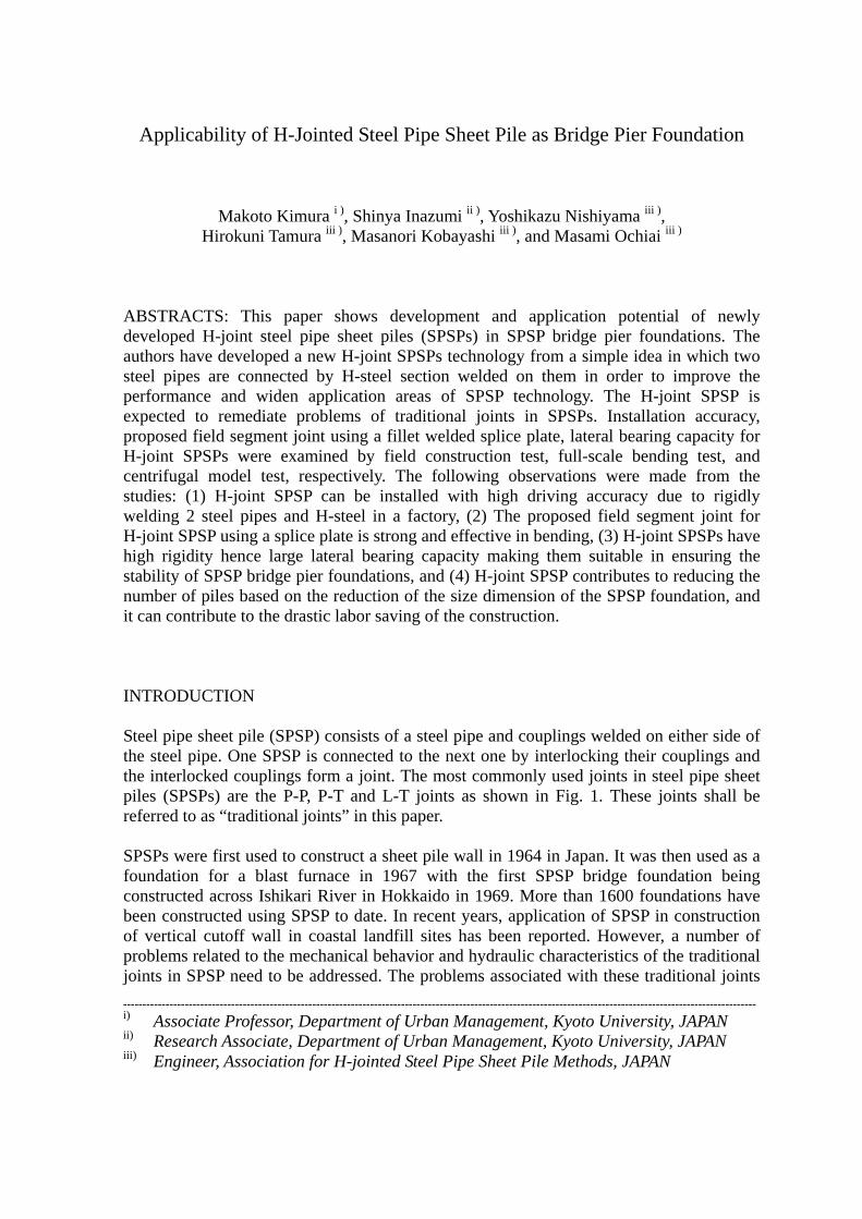
Problems such as low construction accuracy, low rigidity and low waterproof performance are inherent with traditional joints. For over 40 years since SPSP were first used in Japan, however, drastic developments and improvement for existences and shapes of the traditional joint themselves have not been performed, although the few attention has been paid to the enlargement of steel pipe diameter, and joint sections regarding to perfect water interception capacity and high strength. As a representative example for improving traditional joints, Katayama et al. (1993) proposed to increase the bonding strength between injected mortar and the inner surface of P-P joint by increasing the internal surface area of P-P joint with corrugating and checkering the inner surfaces of the joint pipes as shown in Fig. 2. The method, however, had not considered the quality of mortar grouting on the field, and joint interlocking performance due to a low construction accuracy of traditional P-P joint. Longtime customs in which each of SPSP makes interlock by using the traditional joints and the strength of joints increases by injecting the mortar still remain in the SPSP technology. In order to overcome the problems which are inherent in traditional joint sections in SPSPs, it is necessary to reform the concept of joining each steel pipe together using traditional joints, and the shape of traditional joints. For the above reasons, the authors are introducing a new concept and method of inter-pile connection in SPSPs. In this paper, a new joint in SPSP, referred to as H-joint, is introduced to improve the performance and widen application areas of SPSP technology. The H-joint SPSP is
(a) Smooth internal surface
28.6
25.3
(c) Checkerred inner surface
Units: mm
(b) Corrugated inner surface
40
2.5
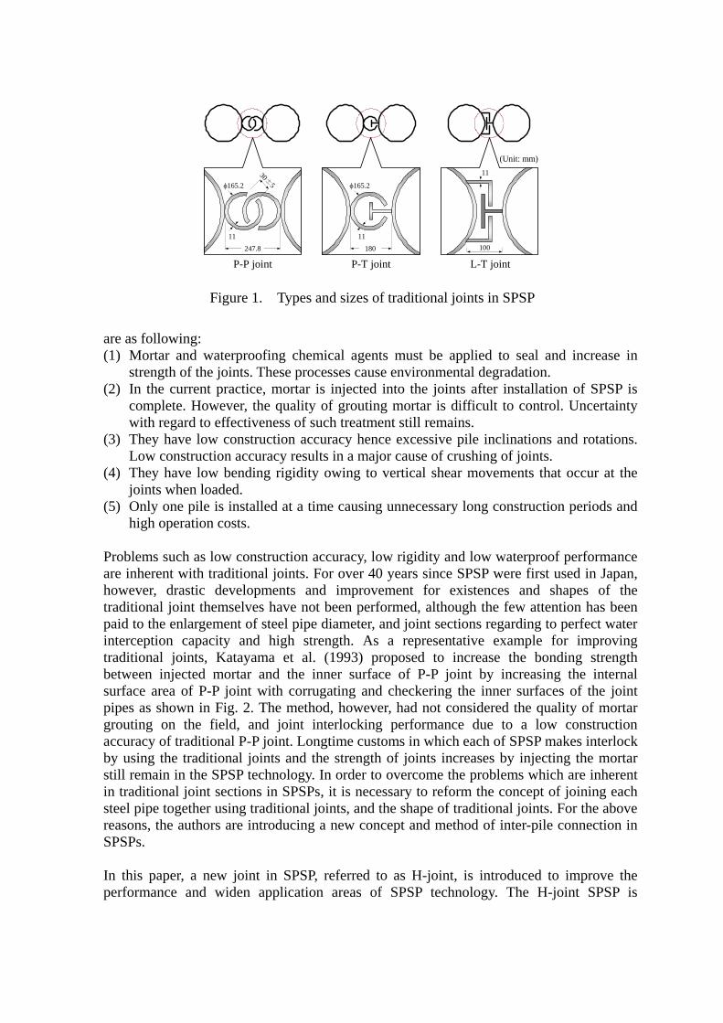
Figure 2. Corrugated and checkered inner surface of P-P joint pipe pile couplings expected to remediate problems of traditional joints in SPSPs. Constructional problems of H-joint SPSP are addressed by conducting full-scale field and laboratory tests. Their mechanical and deformation behavior are assessed by centrifugal model tests and their experiment results are simulated using beam analysis method. The parametric studies using beam analysis are conducted to demonstrate the efficiency of using H-joint SPSP and to estimate its joint efficiency for application in design of SPSP bridge pier foundations. DEVELOPMENT OF H-JOINT STEEL PIPE SHEET PILES The authors have introduced and developed a technology in SPSP aimed at improving their performance and widening their application areas. They have developed a new H-joint from a simple idea in which two steel pipes are connected by H-steel section welded on
Continuosly welded along the pile length
Base steel
Coupling
Base steelH steel
Coupling
(a) Sectional view of H-joint SPSPs
(b) H-joint SPSP segment with P-P couplings
A set H-joint SPSP
CouplingSteel pipe H-steel section
welded
Figure 3. Proposed H-joint SPSP for steel pipe sheet piles application
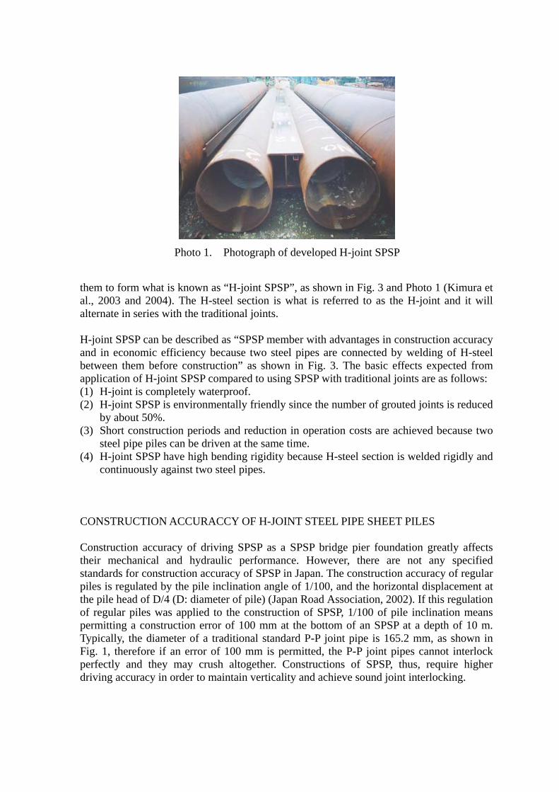
Photo 1. Photograph of developed H-joint SPSP
them to form what is known as “H-joint SPSP”, as shown in Fig. 3 and Photo 1 (Kimura et al., 2003 and 2004). The H-steel section is what is referred to as the H-joint and it will alternate in series with the traditional joints. H-joint SPSP can be described as “SPSP member with advantages in construction accuracy and in economic efficiency because two steel pipes are connected by welding of H-steel between them before construction” as shown in Fig. 3. The basic effects expected from application of H-joint SPSP compared to using SPSP with traditional joints are as follows: (1) H-joint is completely waterproof. (2) H-joint SPSP is environmentally friendly since the number of grouted joints is reduced
by about 50%. (3) Short construction periods and reduction in operation costs are achieved because two
steel pipe piles can be driven at the same time. (4) H-joint SPSP have high bending rigidity because H-steel section is welded rigidly and
continuously against two steel pipes. CONSTRUCTION ACCURACCY OF H-JOINT STEEL PIPE SHEET PILES Construction accuracy of driving SPSP as a SPSP bridge pier foundation greatly affects their mechanical and hydraulic performance. However, there are not any specified standards for construction accuracy of SPSP in Japan. The construction accuracy of regular piles is regulated by the pile inclination angle of 1/100, and the horizontal displacement at the pile head of D/4 (D: diameter of pile) (Japan Road Association, 2002). If this regulation of regular piles was applied to the construction of SPSP, 1/100 of pile inclination means permitting a construction error of 100 mm at the bottom of an SPSP at a depth of 10 m. Typically, the diameter of a traditional standard P-P joint pipe is 165.2 mm, as shown in Fig. 1, therefore if an error of 100 mm is permitted, the P-P joint pipes cannot interlock perfectly and they may crush altogether. Constructions of SPSP, thus, require higher driving accuracy in order to maintain verticality and achieve sound joint interlocking.
Single headvibrohammer
Double headattachment
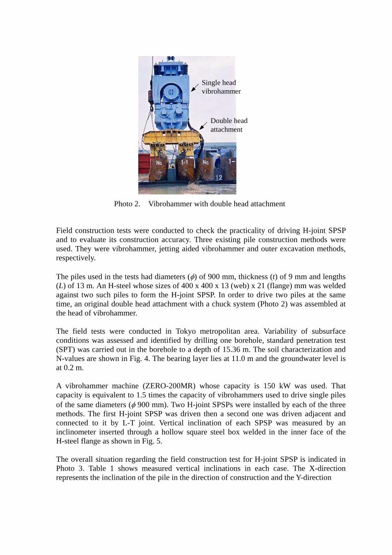
Photo 2. Vibrohammer with double head attachment
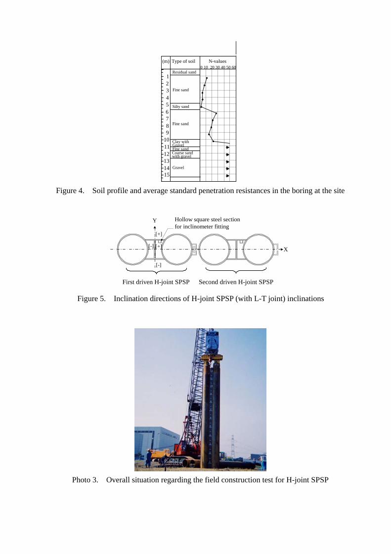
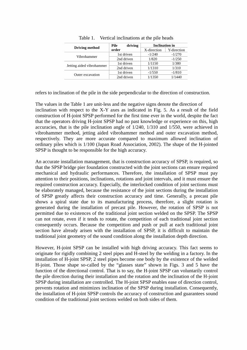
Field construction tests were conducted to check the practicality of driving H-joint SPSP and to evaluate its construction accuracy. Three existing pile construction methods were used. They were vibrohammer, jetting aided vibrohammer and outer excavation methods, respectively. The piles used in the tests had diameters (φ) of 900 mm, thickness (t) of 9 mm and lengths (L) of 13 m. An H-steel whose sizes of 400 x 400 x 13 (web) x 21 (flange) mm was welded against two such piles to form the H-joint SPSP. In order to drive two piles at the same time, an original double head attachment with a chuck system (Photo 2) was assembled at the head of vibrohammer. The field tests were conducted in Tokyo metropolitan area. Variability of subsurface conditions was assessed and identified by drilling one borehole, standard penetration test (SPT) was carried out in the borehole to a depth of 15.36 m. The soil characterization and N-values are shown in Fig. 4. The bearing layer lies at 11.0 m and the groundwater level is at 0.2 m. A vibrohammer machine (ZERO-200MR) whose capacity is 150 kW was used. That capacity is equivalent to 1.5 times the capacity of vibrohammers used to drive single piles of the same diameters (φ 900 mm). Two H-joint SPSPs were installed by each of the three methods. The first H-joint SPSP was driven then a second one was driven adjacent and connected to it by L-T joint. Vertical inclination of each SPSP was measured by an inclinometer inserted through a hollow square steel box welded in the inner face of the H-steel flange as shown in Fig. 5. The overall situation regarding the field construction test for H-joint SPSP is indicated in Photo 3. Table 1 shows measured vertical inclinations in each case. The X-direction represents the inclination of the pile in the direction of construction and the Y-direction
N-values0 10 20 30 40 50 60
Type of soil(m)
Gravel
Residual sand
Fine sand
Silty sand
Fine sand
Fine sandCoarse sandwith gravel
Clay with
Gravel
123456789
101112131415
Figure 4. Soil profile and average standard penetration resistances in the boring at the site
Y
[+]
[+]
[-]
[-]
Hollow square steel sectionfor inclinometer fitting
X
First driven H-joint SPSP Second driven H-joint SPSP
Figure 5. Inclination directions of H-joint SPSP (with L-T joint) inclinations
Photo 3. Overall situation regarding the field construction test for H-joint SPSP
D
Jetting
O
refers to inclination o The values in the Tabinclination with respconstruction of H-joithat the operators driaccuracies, that is thvibrohammer methorespectively. They ordinary piles whichSPSP is thought to be An accurate installatthat the SPSP bridge mechanical and hydattention to their posrequired constructionbe elaborately managof SPSP greatly affshows a spiral stategenerated during thepermitted due to exiscan not rotate, even consequently occurssection have alreadytraditional joint geom However, H-joint SPoriginate for rigidly cinstallation of H-joinH-joint. Those shapfunction of the directhe pile direction durSPSP during installatprevents rotation andthe installation of H-condition of the tradi
Table 1. Vertical inclinations at the pile heads Inclination in riving method Pile driving
order X-direction Y-direction 1st driven -1/240 -1/270 Vibrohammer 2nd driven 1/820 -1/250 1st driven 1/1150 1/380 aided vibrohammer 2nd driven 1/1310 1/310 1st driven -1/550 -1/810 uter excavation
2nd driven 1/1350 1/1440f the pile in the side perpendicular to the direction of construction.
le 1 are unit-less and the negative signs denote the direction of ect to the X-Y axes as indicated in Fig. 5. As a result of the field nt SPSP performed for the first time ever in the world, despite the fact ving H-joint SPSP had no past knowledge or experience on this, high e pile inclination angle of 1/240, 1/310 and 1/550, were achieved in d, jetting aided vibrohammer method and outer excavation method, are more accurate compared to maximum allowed inclination of is 1/100 (Japan Road Association, 2002). The shape of the H-jointed responsible for the high accuracy.
ion management, that is construction accuracy of SPSP, is required, so pier foundation constructed with the joint sections can ensure required raulic performances. Therefore, the installation of SPSP must pay itions, inclinations, rotations and joint intervals, and it must ensure the accuracy. Especially, the interlocked condition of joint sections must ed, because the resistance of the joint sections during the installation
ects their construction accuracy and time. Generally, a precast pile due to its manufacturing process, therefore, a slight rotation is installation of precast pile. However, the rotation of SPSP is not tences of the traditional joint section welded on the SPSP. The SPSP if it tends to rotate, the competition of each traditional joint section . Because the competition and push or pull at each traditional joint arisen with the installation of SPSP, it is difficult to maintain the etry of the sound condition along the installation depth direction.
SP can be installed with high driving accuracy. This fact seems to ombining 2 steel pipes and H-steel by the welding in a factory. In the t SPSP, 2 steel pipes become one body by the existence of the welded e so-called by the “glasses state” shown in Figs. 3 and 5 have the tional control. That is to say, the H-joint SPSP can voluntarily control ing their installation and the rotation and the inclination of the H-joint ion are controlled. The H-joint SPSP enables ease of direction control, minimizes inclination of the SPSP during installation. Consequently, joint SPSP controls the accuracy of construction and guarantees sound tional joint sections welded on both sides of them.
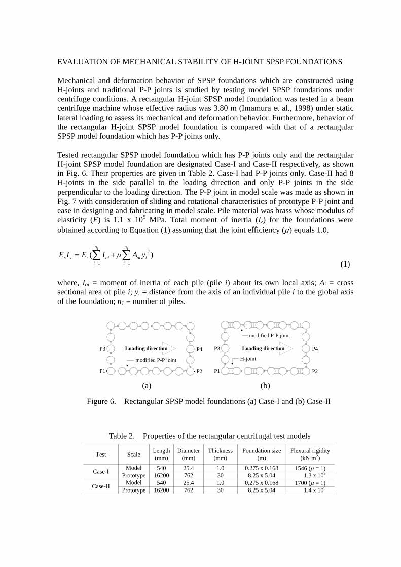
EVALUATION OF MECHANICAL STABILITY OF H-JOINT SPSP FOUNDATIONS Mechanical and deformation behavior of SPSP foundations which are constructed using H-joints and traditional P-P joints is studied by testing model SPSP foundations under centrifuge conditions. A rectangular H-joint SPSP model foundation was tested in a beam centrifuge machine whose effective radius was 3.80 m (Imamura et al., 1998) under static lateral loading to assess its mechanical and deformation behavior. Furthermore, behavior of the rectangular H-joint SPSP model foundation is compared with that of a rectangular SPSP model foundation which has P-P joints only. Tested rectangular SPSP model foundation which has P-P joints only and the rectangular H-joint SPSP model foundation are designated Case-I and Case-II respectively, as shown in Fig. 6. Their properties are given in Table 2. Case-I had P-P joints only. Case-II had 8 H-joints in the side parallel to the loading direction and only P-P joints in the side perpendicular to the loading direction. The P-P joint in model scale was made as shown in Fig. 7 with consideration of sliding and rotational characteristics of prototype P-P joint and ease in designing and fabricating in model scale. Pile material was brass whose modulus of elasticity (E) is 1.1 x 10⁵ MPa. Total moment of inertia (Iz) for the foundations were obtained according to Equation (1) assuming that the joint efficiency (µ) equals 1.0.
)( 2
11
11
i
n
ioi
n
ioiszs yAIEIE ∑∑
==
+= µ (1)
where, Ioi = moment of inertia of each pile (pile i) about its own local axis; Ai = cross sectional area of pile i; yi = distance from the axis of an individual pile i to the global axis of the foundation; n1 = number of piles.
H-joint
modified P-P joint
P2P1
P3 P4
modified P-P joint
P1 P2
P4P3
(a) (b)
Loading direction Loading direction
Figure 6. Rectangular SPSP model foundations (a) Case-I and (b) Case-II
Table 2. Properties of the rectangular centrifugal test models
Test Scale Length(mm)
Diameter(mm)
Thickness(mm)
Foundation size(m)
Flexural rigidity (kN·m2)
Model 540 25.4 1.0 0.275 x 0.168 1546 (µ = 1) Case-I Prototype 16200 762 30 8.25 x 5.04 1.3 x 10⁹
Model 540 25.4 1.0 0.275 x 0.168 1700 (µ = 1) Case-II Prototype 16200 762 30 8.25 x 5.04 1.4 x 10⁹
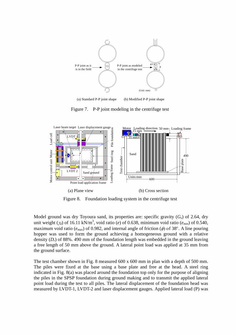
P-P joint as itis in the field
P-P joint as modeledin the centrifuge test
(a) Standard P-P joint shape (b) Modified P-P joint shape
5
φ38
(Unit: mm)
Figure 7. P-P joint modeling in the centrifuge test
LVDT 2
LVDT 1
Sand ground
Load
ing
fram
e
Mot
orM
otor
con
trol u
nit
Pile
foun
datio
nLaser displacement gaugeLaser beam target
Load
cel
l
Stee
l rin
g
Point load application frame
Motor
Bas
e pl
ate
Pile
Loading frame
490
Loading direction
600
Sand
50 mm
Test
cha
mbe
r
35 mm
Units:mm
Sand
15 mm
(a) Plane view (b) Cross section
Figure 8. Foundation loading system in the centrifuge test
Model ground was dry Toyoura sand, its properties are: specific gravity (Gs) of 2.64, dry unit weight (γd) of 16.11 kN/m3, void ratio (e) of 0.638, minimum void ratio (emin) of 0.540, maximum void ratio (emax) of 0.982, and internal angle of friction (φ) οf 38°. A line pouring hopper was used to form the ground achieving a homogeneous ground with a relative density (Dr) of 88%. 490 mm of the foundation length was embedded in the ground leaving a free length of 50 mm above the ground. A lateral point load was applied at 35 mm from the ground surface. The test chamber shown in Fig. 8 measured 600 x 600 mm in plan with a depth of 500 mm. The piles were fixed at the base using a base plate and free at the head. A steel ring indicated in Fig. 8(a) was placed around the foundation top only for the purpose of aligning the piles in the SPSP foundation during ground making and to transmit the applied lateral point load during the test to all piles. The lateral displacement of the foundation head was measured by LVDT-1, LVDT-2 and laser displacement gauges. Applied lateral load (P) was
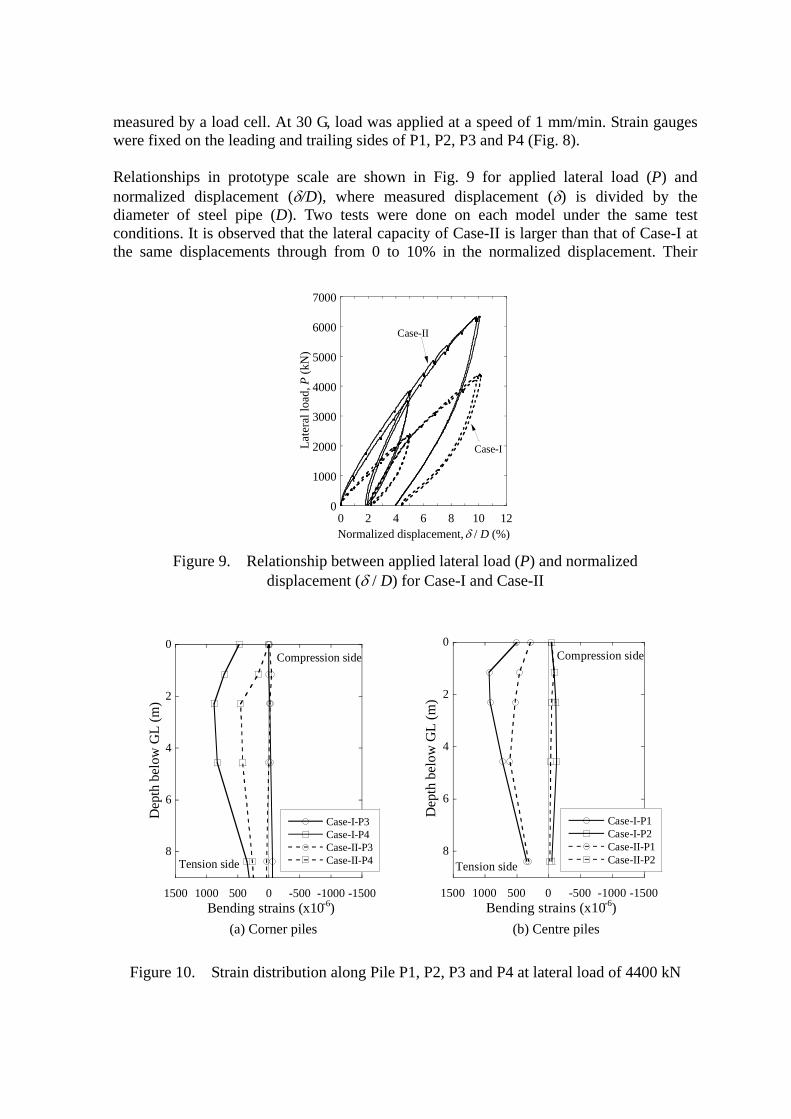
measured by a load cell. At 30 G, load was applied at a speed of 1 mm/min. Strain gauges were fixed on the leading and trailing sides of P1, P2, P3 and P4 (Fig. 8). Relationships in prototype scale are shown in Fig. 9 for applied lateral load (P) and normalized displacement (δ/D), where measured displacement (δ) is divided by the diameter of steel pipe (D). Two tests were done on each model under the same test conditions. It is observed that the lateral capacity of Case-II is larger than that of Case-I at the same displacements through from 0 to 10% in the normalized displacement. Their
0
1000
2000
3000
4000
5000
6000
7000
0 2 4
Late
ral l
oad,
P (k
N)
Normalized d
C
Figure 9. Relationship between apdisplacement (δ / D)
-1500-1000-500050010001500
0
2
4
6
8
Case-I-P3Case-I-P4Case-II-P3Case-II-P4
Bending strains (x10-6)
Dep
th b
elow
GL
(m)
Compression side
Tension side
(a) Corner piles
Figure 10. Strain distribution along Pile
6 8 10 1isplacement, δ / D (%)
ase-II
Case-I
2
plied lateral load (P) and normalized for Case-I and Case-II
-1500-1000-500050010001500
0
2
4
6
8
Case-I-P1Case-I-P2Case-II-P1Case-II-P2
Bending strains (x10-6)
Dep
th b
elow
GL
(m)
Compression side
Tension side
(b) Centre piles
P1, P2, P3 and P4 at lateral load of 4400 kN
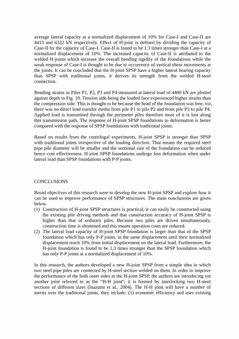
average lateral capacity at a normalized displacement of 10% for Case-I and Case-II are 4413 and 6332 kN respectively. Effect of H-joint is defined by dividing the capacity of Case-II by the capacity of Case-I. Case-II is found to be 1.3 times stronger than Case-I at a normalized displacement of 10%. The increased capacity of Case-II is attributed to the welded H-joints which increase the overall bending rigidity of the foundations while the weak response of Case-I is thought to be due to occurrence of vertical shear movements at the joints. It can be concluded that the H-joint SPSP have a higher lateral bearing capacity than SPSP with traditional joints, it derives its strength from the welded H-steel connection. Bending strains in Piles P1, P2, P3 and P4 measured at lateral load of 4400 kN are plotted against depth in Fig. 10. Tension side being the loaded face experienced higher strains than the compression side. This is thought to be because the head of the foundation was free, viz, there was no direct load transfer media from pile P1 to pile P2 and from pile P3 to pile P4. Applied load is transmitted through the perimeter piles therefore most of it is lost along this transmission path. The response of H-joint SPSP foundations to deformation is better compared with the response of SPSP foundations with traditional joints. Based on results from the centrifugal experiments, H-joint SPSP is stronger than SPSP with traditional joints irrespective of the loading direction. That means the required steel pipe pile diameter will be smaller and the sectional size of the foundation can be reduced hence cost effectiveness. H-joint SPSP foundations undergo less deformation when under lateral load than SPSP foundations with P-P joints. CONCLUSIONS Broad objectives of this research were to develop the new H-joint SPSP and explore how it can be used to improve performance of SPSP structures. The main conclusions are given below. (1) Construction of H-joint SPSP structures is practical, it can easily be constructed using
the existing pile driving methods and that construction accuracy of H-joint SPSP is higher than that of ordinary piles. Because two piles are driven simultaneously, construction time is shortened and this means operation costs are reduced.
(2) The lateral load capacity of H-joint SPSP foundation is larger than that of the SPSP foundation which has only P-P joints, in the same displacement until their normalized displacement reach 10% from initial displacement on the lateral load. Furthermore, the H-joint foundation is found to be 1.3 times stronger than the SPSP foundation which has only P-P joints at a normalized displacement of 10%.
In this research, the authors developed a new H-joint SPSP from a simple idea in which two steel pipe piles are connected by H-steel section welded on them. In order to improve the performance of the both outer sides in the H-joint SPSP, the authors are introducing yet another joint referred to as the “H-H joint"; it is formed by interlocking two H-steel sections of different sizes (Inazumi et al., 2004). The H-H joint will have a number of merits over the traditional joints, they include: (1) economic efficiency and uses existing
H-steel sections, (2) high rigidity, and (3) low hydraulic conductivity in the joint part. The H-H joint is designed to increase the overall strength of the SPSP structures which use H-joint SPSP. The mechanical characteristics such as the compression, tension and shear property for the H-H joint will be verified. In addition, the applicability of the H-joint SPSPs with H-H joints on SPSP structures will be verified by originally developing three dimensional frame analysis which can express the mechanical characteristic of the joint sections in SPSP structures more in detail. REFERENCES Imamura, S., Hagiwara, T. and Nomoto, T. (1998): Nishimatsu dynamic geotechnical
centrifuge, Proceedings of the International Conference on Centrifuge 98, pp.25-30. Inazumi, S., Kimura, M., Too, A.J.K., Nishiyama, Y. and Kamon, M. (2004): Permeability
of H-H joint in H-jointed steel pipe sheet piles at coastal landfill site, Proceedings of Fifteenth Southeast Asian Geotechnical Conference, pp.635-640.
Japanese Association for Steel Pipe Piles (1999): Steel Pipe Sheet Pile Foundations -Design and Construction-, Japanese Association for Steel Pipe Piles, (in Japanese).
Japan Road Association (2002): Reference for Highway Bridge Design Specifications for Highway Bridges: Part IV; Substructures, Japan Road Association.
Katayama, T., Nishimura, S. and Sakamoto, S. (1993): Recent developments in steel pipe sheet pile methods, Foundation Mechanics, Vol.11, pp.32-42, (in Japanese).
Kimura, M., Too, A.J.K., Inazumi, S., Isobe, K. and Nishiyama, Y. (2004): Innovative development of steel pipe sheet pile joint, Proceedings of the Third Civil Engineering Conference in the Asian Region, pp.373-377.
Kimura, M., Too, A.J.K., Isobe, K. and Nishiyama, Y. (2003): Offshore construction of bulkhead waste facilities by H-joint steel pipe sheet piles, Proceedings of International Conference on Foundations; ‘Innovations, Observations, Design and Practice’, pp.443-452.
Public Works Research Institute (1977): Design of Sheet Pile Foundation, Public Works Research Institute, 1175 (1), (in Japanese).
Too, A.J.K., Kimura, M., Inazumi, S., Isobe, K. and Nishiyama, Y. (2004): Improvement of stability of steel pipe sheet pile structures using H-joints, Proceedings of the International Symposium on Engineering Practices and Performance of Soil Deposits (IS-OSAKA 2004), pp.507-512.