Embed Size (px)
Citation preview
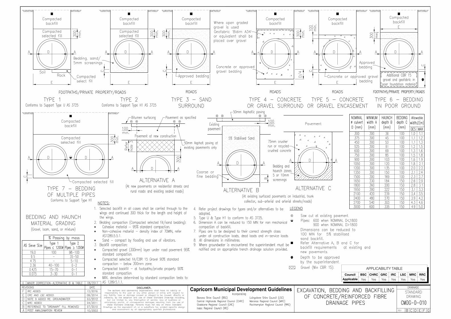
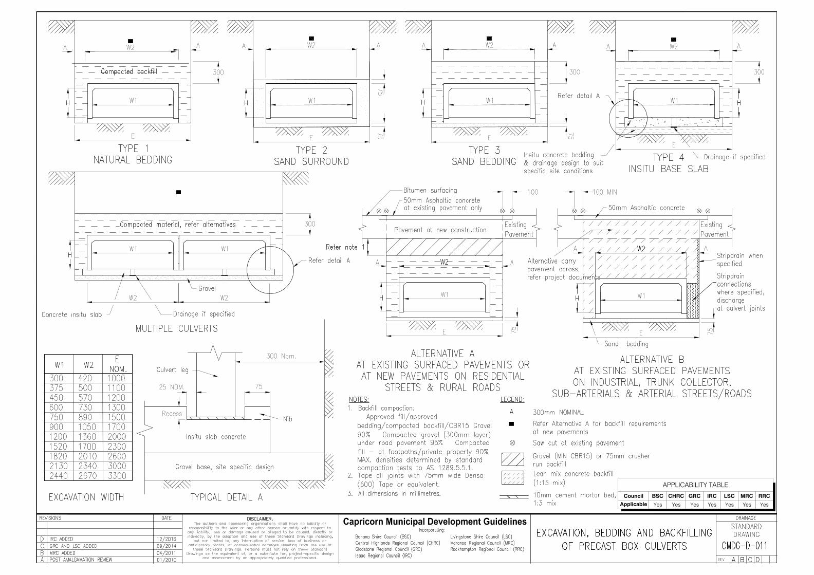
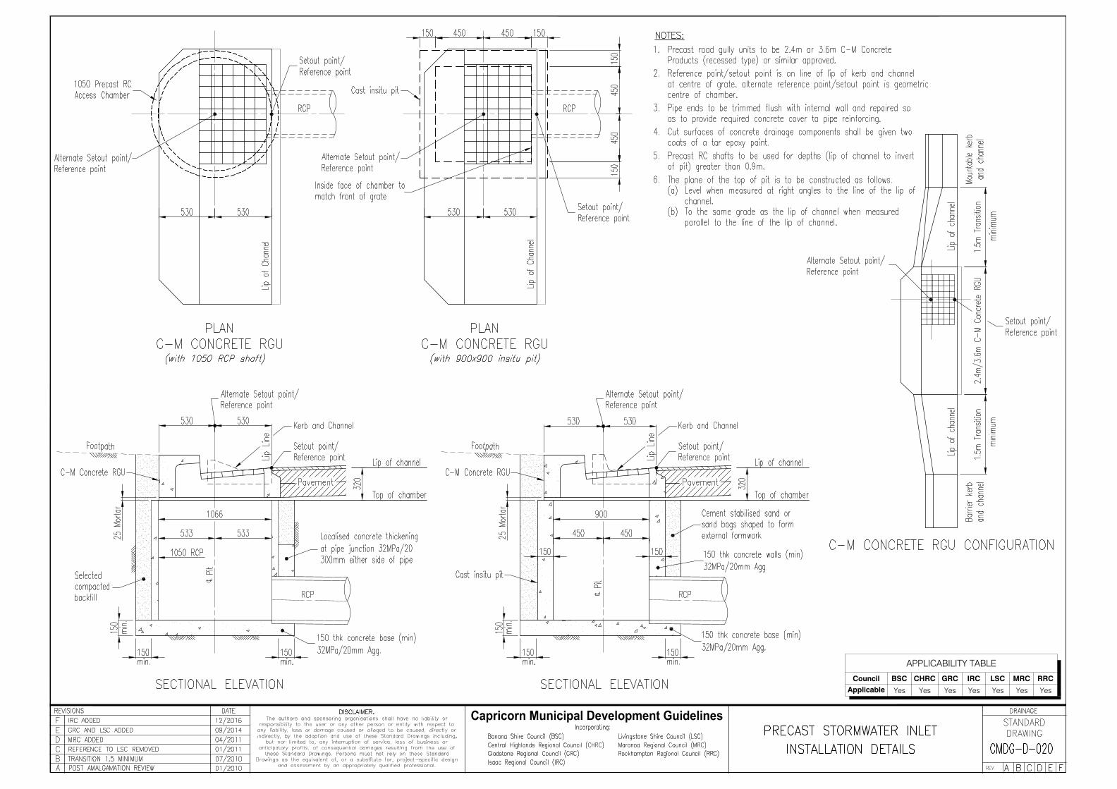
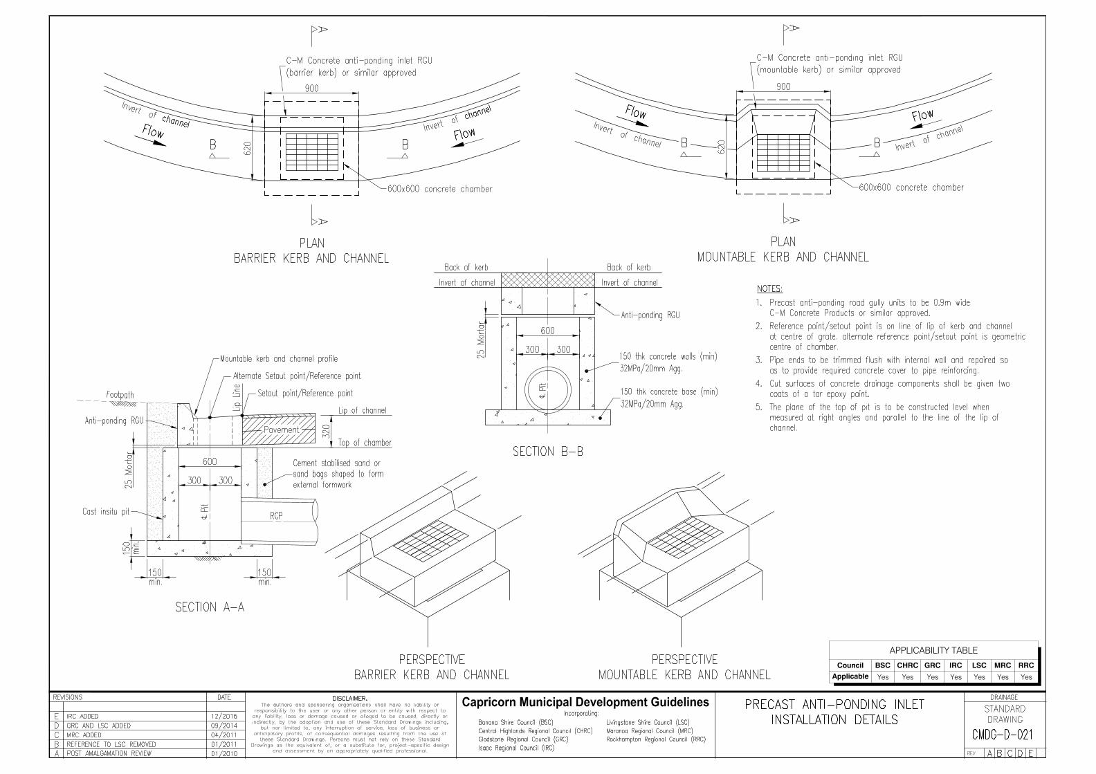
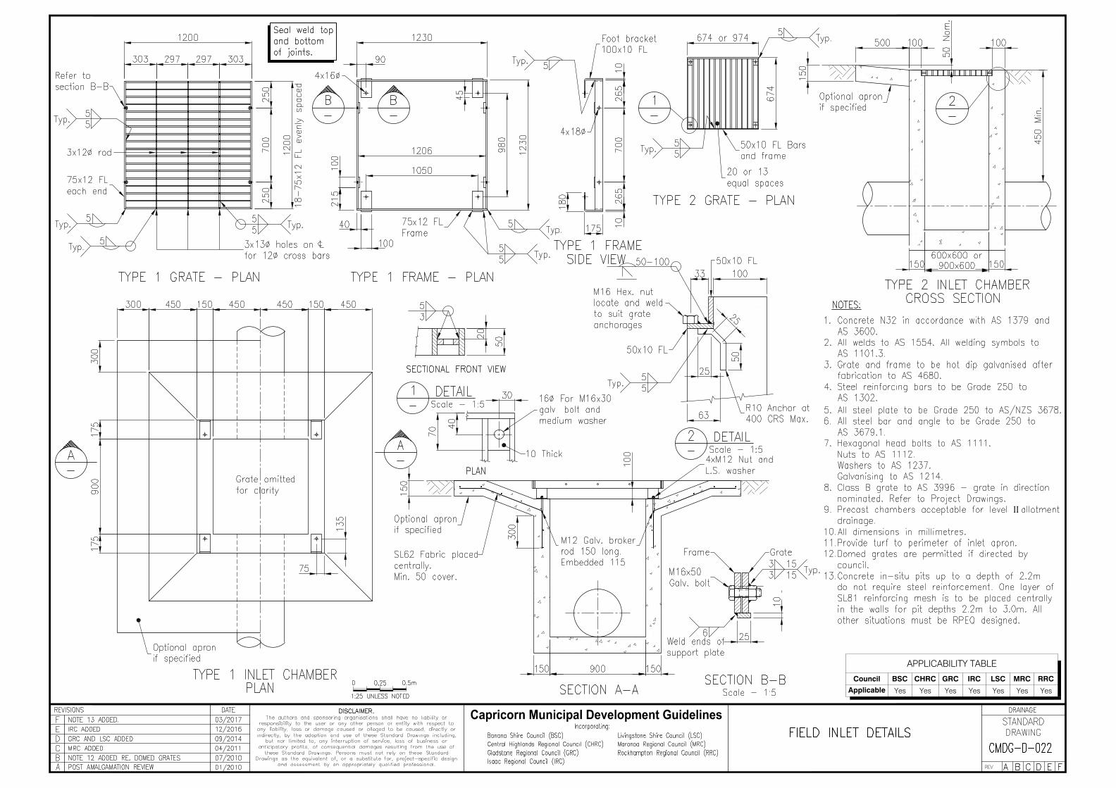
APPLICABILITY TABLE
Council BSC CHRC GRC IRC LSC MRC RRC
Applicable Yes Yes Yes Yes Yes Yes Yes
APPLICABILITY TABLE
Council BSC CHRC GRC IRC LSC MRC RRC
Applicable Yes Yes Yes Yes Yes Yes Yes
APPLICABILITY TABLE
Council BSC CHRC GRC IRC LSC MRC RRC
Applicable Yes Yes Yes Yes Yes Yes Yes
APPLICABILITY TABLE
Council BSC CHRC GRC IRC LSC MRC RRC
Applicable Yes Yes Yes Yes Yes Yes Yes
APPLICABILITY TABLE
Council BSC CHRC GRC IRC LSC MRC RRC
Applicable Yes Yes Yes Yes Yes Yes Yes
TYPICAL SECTION
ACCESS CHAMBER DETAILS
LIFTING ANCHOR LOCATIONSROOF RINGPLAN
(Refer Note 4)
LC
CL
INLET OUTLET
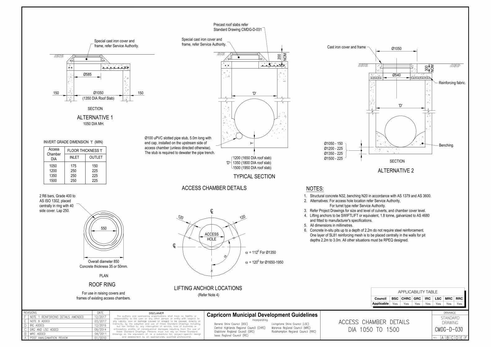
INVERT GRADE DIMENSION 't' (MIN)
1050 DIA MH.ALTERNATIVE 1
FLOOR THICKNESS 't'
SECTION
ALTERNATIVE 2SECTION
Ø585
150 Ø1050 150
550
'D'
200
't'
300
Ø1050
Ø540
120120
ACCESS
(1350 DIA Roof Slab)
HOLE
a = 1120 For Ø1350
a = 1200 for Ø1650-1950
a
NOM
NOM
Overall diameter 850Concrete thickness 35 or 50mm.
For use in raising covers andframes of existing access chambers.
1200 (1650 DIA roof slab)'D' 1350 (1800 DIA roof slab) 1500 (1950 DIA roof slab)
Ø1050 - 150Ø1200 - 225Ø1350 - 225Ø1500 - 225
'D'
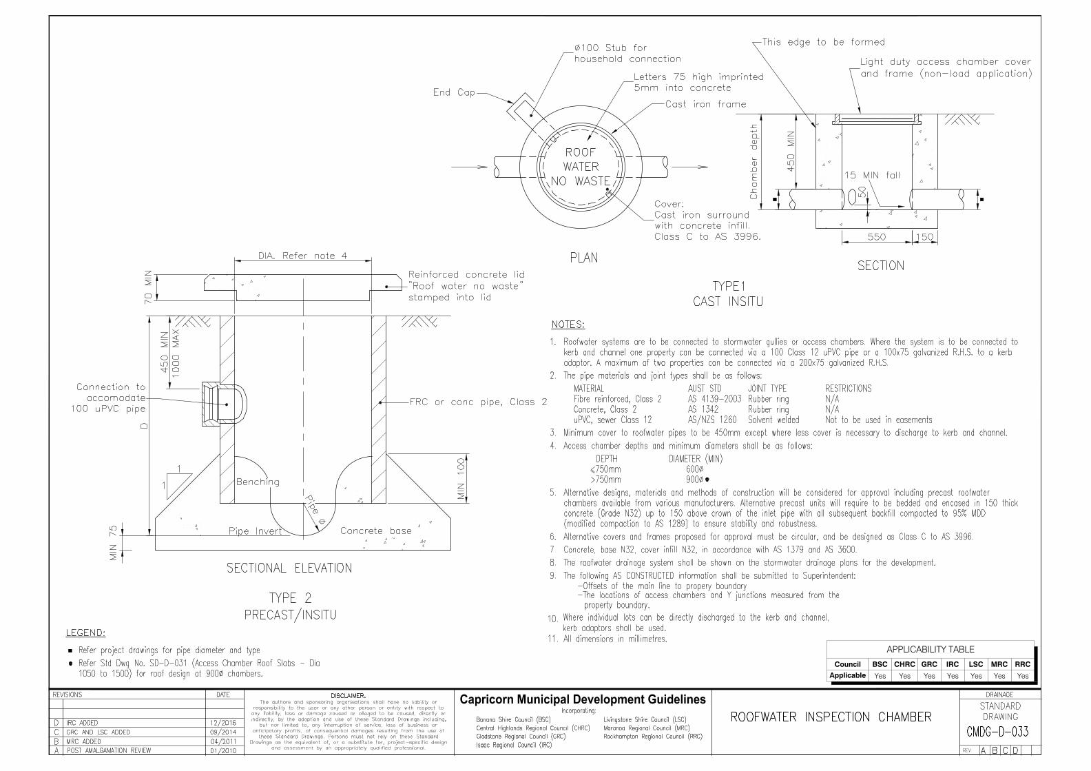
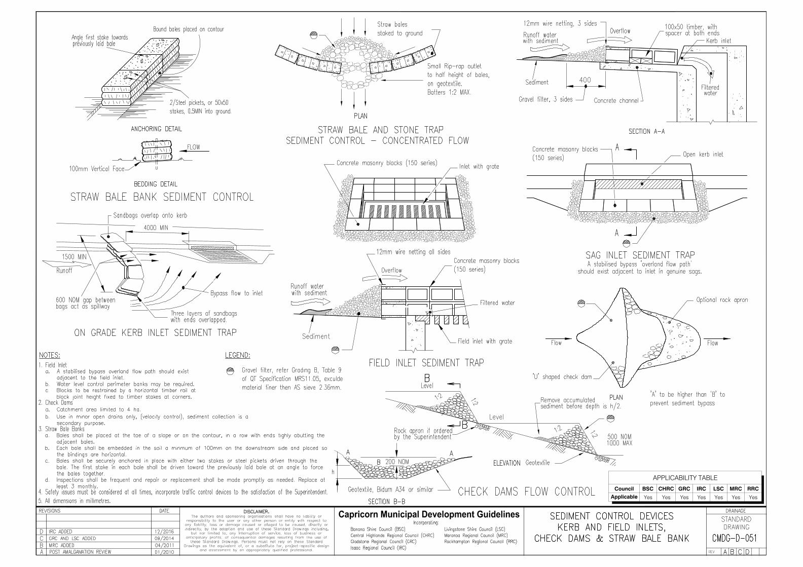
NOTES:
Capricorn Municipal Development Guidelines
APPLICABILITY TABLE
Council BSC CHRC GRC IRC LSC MRC RRC
Applicable Yes Yes Yes Yes Yes Yes Yes
1. Structural concrete N32, benching N20 in accordance with AS 1379 and AS 3600.2. Alternatives: For access hole location refer Service Authority,
For turret type refer Service Authority.3. Refer Project Drawings for size and level of culverts, and chamber cover level.4. Lifting anchors to be SWIFTLIFT or equivalent, 1.8 tonne, galvanized to AS 4680
and fitted to manufacturer's specifications.5. All dimensions in millimetres.6. Concrete in-situ pits up to a depth of 2.2m do not require steel reinforcement.
One layer of SL81 reinforcing mesh is to be placed centrally in the walls for pitdepths 2.2m to 3.0m. All other situations must be RPEQ designed.
Special cast iron cover andframe, refer Service Authority.
Special cast iron cover andframe, refer Service Authority.
Precast roof slabs referStandard Drawing CMDG-D-031
Cast iron cover and frame
Reinforcing fabric.
Benching.Access
ChamberDIA
1050 175 1501200 250 2251350 250 2251500 250 225
2 R6 bars, Grade 400 toAS ISO 1302, placedcentrally in ring with 40side cover. Lap 250.
Ø100 uPVC slotted pipe stub, 5.0m long withend cap, installed on the upstream side ofaccess chamber (unless directed otherwise).The stub is required to dewater the pipe trench.
8
100 C\C
75 C\C656
3
12
4
10
==
150 Walls Slab thickness 1757
9
78
150
BARNo. SHAPE a/b OVERALL
LENGTH1 937 1175 1
12551125510302
4 1175 1400 1 140013501135011253
7 1000 1225 2 24502100210508128
6 1125 1350 2 270014501145012255
10 1200 4200 1 42002550125506859
1175
No.OFF
TOTALLENGTH
TOTAL 20630
1050 DIA ACCESS CHAMBER
1350 Dia
150
100 C\C
75
50
94
23
9
1
12
75 C\C75 C\C
10
78
67
58
11
10
1200 DIA ACCESS CHAMBER
23200TOTAL
TOTALLENGTH
No.OFF
1425
9
685 2550 1 25505150151501500
10
5 1520 1745 1 174517751177515376
8
1050 1275 2 25503050215251300
7
3 1450 1675 1 167517251172515004
2 1400 1625 1 16251142512001
OVERALLLENGTHa/bSHAPEBAR
No.
1211
13751450
16001675 2
2 32003350
a
b
b
a
150= =
1650 Dia225 Walls Slab thickness 175
75 C\C
150 C\C
50150 C/C 150 C/C
75225
100 C\C
11
89
10
12
7
568
10
11
9
150 C\C
3
2
1
13
4
100 C\C75 C\C
a
b
190036502
119001825
16751600
1213
BARNo. SHAPE a/b OVERALL
LENGTH1 1275 1500 1
17251172514882
4 1645 1870 1 187018501185016123
7
1525 1750 2 3500
3000215001262
8
6 1675 1900 1 190019001190016755
11
1650 5625 1 5625255012550685
9
1500
No.OFF
TOTALLENGTH
TOTAL 34270
1350 DIA ACCESS CHAMBER
10 1412 1650 2 3300
==150
1800 Dia225 Walls Slab thickness 200
50
75225
13 14
11
10
87
910
12
150 C\C75 C\C
5
34
1
216
6
12
1413
11
100 C\C
400022000176210
1500 DIA ACCESS CHAMBER
43925TOTAL
TOTALLENGTH
No.OFF
9
685 2550 1161001800
14
5 1756 1980 11202518006
8
1275 1500 2 3000
120501825
7
3 1645 1870 11195017124
2 1575 1800 11157513371
OVERALLLENGTHa/bSHAPEBAR
No.
1615
18371825
20752050 1
1
b
a
111213
38502192517001600 1825 2 36501462 1700 2 3400
61002550
20502075
15751800
19501870
2050
20251980
225 Walls Slab thickness 2001950 Dia
150= =
100 C\C
100 C\C15
50
75225
REINFORCEMENT DIMENSIONS
bN12 Bars
Lap 400
aN12 Bars50
50125
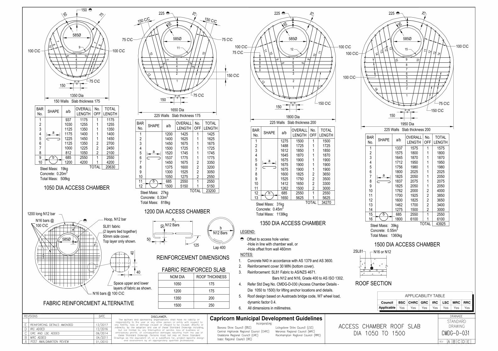
ROOF THICKNESSNOM DIAFABRIC REINFORCED SLAB
1050 175
20013501200 175
1500 250
585Ø
585Ø585Ø 585Ø 585Ø
N16 bars @ 100 C\C
1200 long N12 barHoop, N12 bar
40
40
FABRIC REINFORCMENT ALTERNATIVE
ROOF SECTION
N16 or N122SL81NOTES:
LEGEND:
Capricorn Municipal Development Guidelines
APPLICABILITY TABLE
Council BSC CHRC GRC IRC LSC MRC RRC
Applicable Yes Yes Yes Yes Yes Yes Yes
SL81 fabric(2 layers tied together)50mm side cover.Top layer only shown.
Space upper and lowerlayers of fabric as shown.
N16 bars @100 C\C
1. Concrete N40 in accordance with AS 1379 and AS 3600.2. Reinforcement cover 30 MIN (bottom cover).3. Reinforcement: SL81 Fabric to AS/NZS 4671.
Bars N12 and N16, Grade 400 to AS ISO 1302.4. Refer Std Dwg No. CMDG-D-030 (Access Chamber Details -
Dia 1050 to 1500) for lifting anchor locations and details.5. Roof design based on Austroads bridge code, W7 wheel load,
dynamic factor 0.4.6. All dimensions in millimetres.
Steel Mass: 27kgConcrete: 0.33m3
Total Mass: 818kg Steel Mass: 31kgConcrete: 0.45m3
Total Mass: 1138kg
Steel Mass: 19kgConcrete: 0.20m3
Total Mass: 508kg
Steel Mass: 39kgConcrete: 0.55m3
Total Mass: 1360kgOffset to access hole varies:-Hole in line with chamber wall, or-Hole offset from wall 460mm
N12 U-bars laid flat, legs tolap main bars, refer TypicalSlab Reinforcement
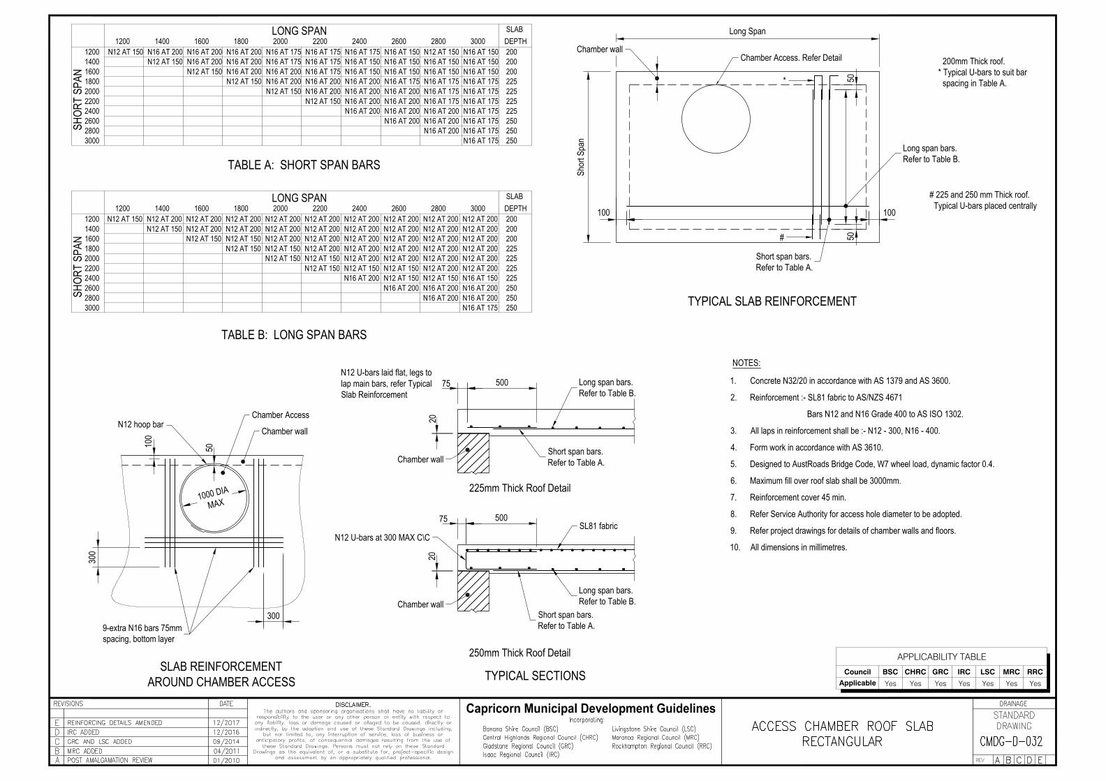
# 225 and 250 mm Thick roof. Typical U-bars placed centrally
200mm Thick roof.* Typical U-bars to suit bar spacing in Table A.
2600
30002800
2400220020001800160014001200
SHOR
T SP
ANSH
ORT
SPAN
N16 AT 150N16 AT 150N16 AT 150N16 AT 150
N16 AT 150N16 AT 150N16 AT 150N16 AT 150
N16 AT 150
N16 AT 175N16 AT 175N16 AT 175N16 AT 175N16 AT 175N16 AT 175
N16 AT 175N16 AT 175N16 AT 175N16 AT 175
N16 AT 175
N16 AT 175N16 AT 175N16 AT 175
N16 AT 175
N16 AT 200N16 AT 200N16 AT 200N16 AT 200
N16 AT 200N16 AT 200N16 AT 200
N16 AT 200N16 AT 200
N16 AT 200N16 AT 200N16 AT 200N16 AT 200
N16 AT 200N16 AT 200
LONG SPAN1200
1200140016001800200022002400
28003000
2600
1400 1600 1800 2000 2200 2400 2600 2800 3000 DEPTHSLAB
N12 AT 150N12 AT 150
N12 AT 150N12 AT 150
N12 AT 150N12 AT 150
N16 AT 200
N16 AT 175
N16 AT 200N16 AT 200N16 AT 200
N16 AT 200 N16 AT 175 N16 AT 150 N12 AT 150
N16 AT 200
200
225
250
200200
225225225
250250
250250
225225225
200200
250
225
200
N12 AT 150N12 AT 150N12 AT 150N12 AT 150
N12 AT 150N12 AT 150
N12 AT 150N12 AT 200 N12 AT 200
N12 AT 200N12 AT 200
N12 AT 200N12 AT 200N12 AT 200
N12 AT 200N12 AT 200N12 AT 200N12 AT 200
N12 AT 200N12 AT 200N12 AT 200N12 AT 200 N12 AT 200
N12 AT 200N12 AT 200N12 AT 200N12 AT 200 N12 AT 200
N12 AT 200N12 AT 200N12 AT 200N12 AT 200N12 AT 200N12 AT 200N12 AT 200N12 AT 200N12 AT 200N12 AT 200N12 AT 200N12 AT 200 N12 AT 200
N16 AT 150N16 AT 200 N16 AT 200
N16 AT 200N16 AT 200N16 AT 200
N16 AT 175
N16 AT 200N12 AT 150
N12 AT 150N12 AT 150
N12 AT 150N12 AT 150
N12 AT 150
SLABDEPTH3000280026002400220020001800160014001200
LONG SPAN
TYPICAL SECTIONS
TABLE A: SHORT SPAN BARS
TYPICAL SLAB REINFORCEMENT
TABLE B: LONG SPAN BARS
250mm Thick Roof Detail
225mm Thick Roof Detail
NOTES:
Capricorn Municipal Development Guidelines
APPLICABILITY TABLE
Council BSC CHRC GRC IRC LSC MRC RRC
Applicable Yes Yes Yes Yes Yes Yes Yes
N12 hoop barChamber Access
Chamber wall
9-extra N16 bars 75mmspacing, bottom layer
300
300
100
50
SLAB REINFORCEMENTAROUND CHAMBER ACCESS
50075
20
Chamber wallShort span bars.Refer to Table A.
Long span bars.Refer to Table B.
50075SL81 fabric
N12 U-bars at 300 MAX C\C
20
Chamber wallLong span bars.Refer to Table B.
Short span bars.Refer to Table A.
Long Span
Shor
t Spa
n
Chamber wallChamber Access. Refer Detail
* 5050#
100100
Long span bars.Refer to Table B.
Short span bars.Refer to Table A.
1. Concrete N32/20 in accordance with AS 1379 and AS 3600.
2. Reinforcement :- SL81 fabric to AS/NZS 4671
Bars N12 and N16 Grade 400 to AS ISO 1302.
3. All laps in reinforcement shall be :- N12 - 300, N16 - 400.
4. Form work in accordance with AS 3610.
5. Designed to AustRoads Bridge Code, W7 wheel load, dynamic factor 0.4.
6. Maximum fill over roof slab shall be 3000mm.
7. Reinforcement cover 45 min.
8. Refer Service Authority for access hole diameter to be adopted.
9. Refer project drawings for details of chamber walls and floors.
10. All dimensions in millimetres.
1000 DIAMAX
APPLICABILITY TABLE
Council BSC CHRC GRC IRC LSC MRC RRC
Applicable Yes Yes Yes Yes Yes Yes Yes
Capricorn Municipal Development Guidelines
APPLICABILITY TABLE
Council BSC CHRC GRC IRC LSC MRC RRC
Applicable Yes Yes Yes Yes Yes Yes Yes
APPLICABILITY TABLE
Council BSC CHRC GRC IRC LSC MRC RRC
Applicable Yes Yes Yes Yes Yes Yes Yes
APPLICABILITY TABLE
Council BSC CHRC GRC IRC LSC MRC RRC
Applicable Yes Yes Yes Yes Yes Yes Yes
APPLICABILITY TABLE
Council BSC CHRC GRC IRC LSC MRC RRC
Applicable Yes Yes Yes Yes Yes Yes Yes
APPLICABILITY TABLE
Council BSC CHRC GRC IRC LSC MRC RRC
Applicable Yes Yes Yes Yes Yes Yes Yes