Embed Size (px)
Citation preview
Broa
dcas
ting
Appl
icat
ion
Card
| 01
.00
RF signal monitoring in DVB-T2 multi-PLP networks
RF s
igna
l mon
itorin
g in
DVB
-T2
mul
ti-PL
P ne
twor
ks
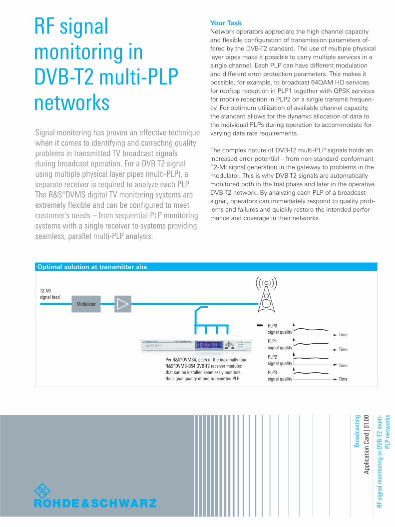
Optimal solution at transmitter site
T2-MIsignal feed
Modulator
Time
Time
Time
Time
Per R&S®DVMS4, each of the maximally four R&S®DVMS-B54 DVB-T2 receiver modules that can be installed seamlessly monitors the signal quality of one transmitted PLP
PLP0signal quality
PLP1signal quality
PLP2signal quality
PLP3signal quality
Your TaskNetwork operators appreciate the high channel capacity and flexible configuration of transmission parameters of‑fered by the DVB‑T2 standard. The use of multiple physical layer pipes make it possible to carry multiple services in a single channel. Each PLP can have different modulation and different error protection parameters. This makes it possible, for example, to broadcast 64QAM HD services for rooftop reception in PLP1 together with QPSK services for mobile reception in PLP2 on a single transmit frequen‑cy. For optimum utilization of available channel capacity, the standard allows for the dynamic allocation of data to the individual PLPs during operation to accommodate for varying data rate requirements.
The complex nature of DVB‑T2 multi‑PLP signals holds an increased error potential – from non‑standard‑conformant T2‑MI signal generation in the gateway to problems in the modulator. This is why DVB‑T2 signals are automatically monitored both in the trial phase and later in the operative DVB‑T2 network. By analyzing each PLP of a broadcast signal, operators can immediately respond to quality prob‑lems and failures and quickly restore the intended perfor‑mance and coverage in their networks.
Signal monitoring has proven an effective technique when it comes to identifying and correcting quality problems in transmitted TV broadcast signals during broadcast operation. For a DVB-T2 signal using multiple physical layer pipes (multi-PLP), a separate receiver is required to analyze each PLP. The R&S®DVMS digital TV monitoring systems are extremely flexible and can be configured to meet customer's needs – from sequential PLP monitoring systems with a single receiver to systems providing seamless, parallel multi-PLP analysis.
DVMS_PLP_ac_en_3606-7276-92_v0100.indd 1 24.07.2012 21:11:28

Rohde & Schwarz GmbH & Co. KG
Europe, Africa, Middle East | +49 89 4129 12345
customersupport@rohde‑schwarz.com
North America | 1 888 TEST RSA (1 888 837 87 72)
[email protected]‑schwarz.com
Latin America | +1 410 910 79 88 | customersupport.la@rohde‑schwarz.com
Asia/Pacific | +65 65 13 04 88 | [email protected]
China | +86 800 810 8228/+86 400 650 5896
customersupport.china@rohde‑schwarz.com
www.rohde‑schwarz.com
R&S® is a registered trademark of Rohde & Schwarz GmbH & Co. KG
Trade names are trademarks of the owners | Printed in Germany (as)
RF signal monitoring in DVB‑T2 multi‑PLP networks |
PD 3606.7276.92 | Version 01.00 | July 2012
Data without tolerance limits is not binding | Subject to change
© 2012 Rohde & Schwarz GmbH & Co. KG | 81671 München, Germany
Cost-effective solution at transmitter site: One R&S®DVMS1 sequentially monitors the signal quality of all transmitted PLPs
PLP0
PLP1
PLP2
PLP3
PLP0
PLP3 PLP2
PLP0 PLP1
Modulator
T2-MIsignal feed
Signal quality
R&S®DVMS1with one R&S®DVMS-B54 receiver module
Time
The individual PLPs can also be monitored sequentially using a single receiver module, which is the more cost‑effective solution and can also be implemented with the more compact R&S®DVMS1. The R&S®Scheduler soft‑ware supports the configuration and control for sequential mode. The operator can define the sequence and moni‑toring periods for any number of PLPs on the clear‑cut user interface. Results are displayed in tabular form. They can be recorded and made available to network manage‑ment systems via the instrument's SNMP interface. If a problem is found in a PLP during sequential analysis, the R&S®DVMS1 can be configured so that the monitoring period will be automatically extended to allow the source of the interference to be captured. In sequential mode, the blind time for each PLP increases with the number of PLPs being monitored. Errors occurring during the blind time go undetected, since during this time another PLP is being analyzed or switchover is taking place between two PLPs. This slows down operator response in the event of an er‑ror and makes it more difficult to detect short‑term errors. Plus, signal quality is not fully documented.
Parallel and sequential monitoring can be combined for an optimal trade‑off between error detection reliability and cost. For example, a dedicated receiver module can be used for seamless monitoring of the PLP carrying the vital live transmission, while two further modules sequentially monitor two PLPs each. This configuration requires only three receiver modules instead of five and yet ensures a reasonably short response time in the event of an error.
T&M solutionThe highly compact R&S®DVMS digital TV monitoring systems provide cost‑effective, high‑quality monitoring of DVB‑T2 multi‑PLP signals at the RF level (MER, BER, etc.) and at the transport stream level in accordance with ETSI TR 101 290. An option lets operators simultaneously monitor T2‑MI signal feeds. Any faults detected can be automatically reported in realtime to a network manage‑ment system via SNMP. PLP monitoring can be carried out directly at the transmitter site and at representative recep‑tion sites to take into account potential, local sources of interference such as neighboring mobile radio channels. Alternatively, PLP monitoring can be performed either at the transmitter site or at representative reception sites.
If the T2‑MI signal feed to the transmitter site is monitored in addition, sources of errors can be traced back to the gateway or the transmitter (see Application Card "Testing and monitoring DVB‑T2 signal feed via new T2‑MI inter‑face"). The highly complex DVB‑T2 multi‑PLP signals re‑quire a separate receiver for analyzing each PLP.
ApplicationThe R&S®DVMS4 can be equipped with up to four DVB‑T2 receiver modules (R&S®DVMS‑B54) to provide seamless, parallel monitoring of all PLPs in a broadcast channel. Op‑erators can instantly respond to any errors or failures and reliably detect even sporadic short‑term errors.
3606727692
DVMS_PLP_ac_en_3606-7276-92_v0100.indd 2 24.07.2012 21:11:28