Embed Size (px)
Citation preview

SINAMICS DCM
DC Converter Application document for functional safety STO, SS1 (ISO 13849-1)
Compact User Manual
09/2016 A5E34871844AM
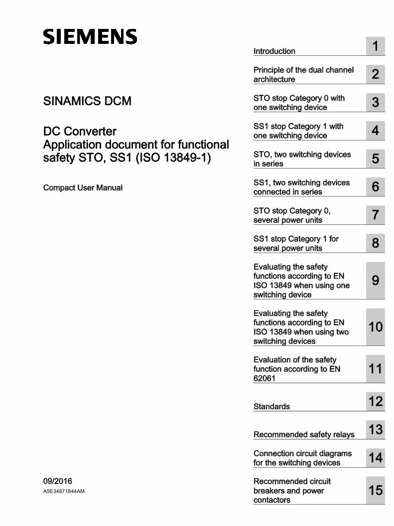
Introduction 1
Principle of the dual channel architecture
2
STO stop Category 0 with one switching device
3
SS1 stop Category 1 with one switching device
4
STO, two switching devices in series
5
SS1, two switching devices connected in series
6
STO stop Category 0, several power units
7
SS1 stop Category 1 for several power units
8
Evaluating the safety functions according to EN ISO 13849 when using one switching device
9
Evaluating the safety functions according to EN ISO 13849 when using two switching devices
10
Evaluation of the safety function according to EN 62061
11
Standards 12
Recommended safety relays 13
Connection circuit diagrams for the switching devices
14
Recommended circuit breakers and power contactors
15
Siemens AG Division Process Industries and Drives Postfach 48 48 90026 NÜRNBERG GERMANY
A5E34871844AM Ⓟ 09/2016 Subject to change
Copyright © Siemens AG . All rights reserved
Legal information Warning notice system
This manual contains notices you have to observe in order to ensure your personal safety, as well as to prevent damage to property. The notices referring to your personal safety are highlighted in the manual by a safety alert symbol, notices referring only to property damage have no safety alert symbol. These notices shown below are graded according to the degree of danger.
DANGER indicates that death or severe personal injury will result if proper precautions are not taken.
WARNING indicates that death or severe personal injury may result if proper precautions are not taken.
CAUTION indicates that minor personal injury can result if proper precautions are not taken.
NOTICE indicates that property damage can result if proper precautions are not taken.
If more than one degree of danger is present, the warning notice representing the highest degree of danger will be used. A notice warning of injury to persons with a safety alert symbol may also include a warning relating to property damage.
Qualified Personnel The product/system described in this documentation may be operated only by personnel qualified for the specific task in accordance with the relevant documentation, in particular its warning notices and safety instructions. Qualified personnel are those who, based on their training and experience, are capable of identifying risks and avoiding potential hazards when working with these products/systems.
Proper use of Siemens products Note the following:
WARNING Siemens products may only be used for the applications described in the catalog and in the relevant technical documentation. If products and components from other manufacturers are used, these must be recommended or approved by Siemens. Proper transport, storage, installation, assembly, commissioning, operation and maintenance are required to ensure that the products operate safely and without any problems. The permissible ambient conditions must be complied with. The information in the relevant documentation must be observed.
Trademarks All names identified by ® are registered trademarks of Siemens AG. The remaining trademarks in this publication may be trademarks whose use by third parties for their own purposes could violate the rights of the owner.
Disclaimer of Liability We have reviewed the contents of this publication to ensure consistency with the hardware and software described. Since variance cannot be precluded entirely, we cannot guarantee full consistency. However, the information in this publication is reviewed regularly and any necessary corrections are included in subsequent editions.
Application document for functional safety STO, SS1 (ISO 13849-1) Compact User Manual, 09/2016, A5E34871844AM 5
Table of contents
1 Introduction................................................................................................................................. 11
1.1 Important note ................................................................................................................... 11
1.2 Preliminary remarks........................................................................................................... 11 1.2.1 Safe Torque Off (STO) ...................................................................................................... 12 1.2.2 Safe Stop 1 (SS1, time-controlled) ..................................................................................... 12 1.2.3 Using EMERGENCY STOP ............................................................................................... 13
1.3 Application overview .......................................................................................................... 13
1.4 Armature circuit with one switching device ......................................................................... 14
1.5 Armature circuit with two switching devices ........................................................................ 14
1.6 Field circuit description ...................................................................................................... 15
1.7 Safety shutdown (E-STOP)................................................................................................ 16
1.8 Parameterizing the digital outputs ...................................................................................... 17
1.9 Parameterizing the digital input for SS1 OFF3 ................................................................... 18
1.10 Abbreviations and circuit diagram symbols ........................................................................ 19
2 Principle of the dual channel architecture ....................................................................................... 21
3 STO stop Category 0 with one switching device .............................................................................. 23
3.1 Description ........................................................................................................................ 23
3.2 STO circuit example with one 3WL circuit breaker ............................................................. 24
3.3 STO circuit example with one power contactor................................................................... 25
4 SS1 stop Category 1 with one switching device ............................................................................... 27
4.1 Description ........................................................................................................................ 27
4.2 SS1 circuit example with one 3WL circuit breaker .............................................................. 28
4.3 SS1 circuit example with one power contactor ................................................................... 29
5 STO, two switching devices in series ............................................................................................. 31
5.1 Description ........................................................................................................................ 31
5.2 STO circuit example with two 3WL circuit breakers connected in series ............................. 32
5.3 STO circuit example with two power contactors connected in series .................................. 33
6 SS1, two switching devices connected in series .............................................................................. 35
6.1 Description ........................................................................................................................ 35
6.2 SS1 circuit example with two 3WL circuit breakers connected in series .............................. 36
6.3 SS1 circuit example with two power contactors connected in series ................................... 37
Table of contents
Application document for functional safety STO, SS1 (ISO 13849-1) 6 Compact User Manual, 09/2016, A5E34871844AM
7 STO stop Category 0, several power units ..................................................................................... 39
7.1 Description .........................................................................................................................39
7.2 STO circuit example with two power units and circuit breakers............................................40
7.3 STO circuit example with two power units and power contactors .........................................41
8 SS1 stop Category 1 for several power units .................................................................................. 43
8.1 Description .........................................................................................................................43
8.2 SS1 circuit example with two power units and circuit breakers ............................................45
8.3 SS1 circuit example with two power units and circuit breakers ............................................46
9 Evaluating the safety functions according to EN ISO 13849 when using one switching device .............. 47
9.1 Evaluation of "Detect" .........................................................................................................48
9.2 Evaluation of "Evaluate" .....................................................................................................49
9.3 Evaluation of "Respond" .....................................................................................................50 9.3.1 Evaluation of "Respond" with one power switching device ..................................................50 9.3.1.1 Evaluation of an 3WL circuit breaker...................................................................................50 9.3.1.2 Evaluation of a power contactor ..........................................................................................52
9.4 Result when using a 3WL circuit breaker ............................................................................53
9.5 Result when using a power contactor .................................................................................53
10 Evaluating the safety functions according to EN ISO 13849 when using two switching devices............. 55
10.1 Evaluation of "Detect" .........................................................................................................56
10.2 Evaluation of "Evaluate" .....................................................................................................57
10.3 Evaluation of "Respond" .....................................................................................................58 10.3.1 Evaluation of "Respond" with two power switching devices .................................................58 10.3.1.1 Evaluation of two 3WL circuit breakers connected in series ................................................58 10.3.1.2 Evaluation of two power contactors connected in series......................................................59 10.3.2 Result of "Respond" with two 3WL circuit breakers .............................................................60 10.3.3 Result of "Respond" with two power contactors ..................................................................60
10.4 Result when using two 3WL circuit breakers .......................................................................60
10.5 Result when using two power contactors ............................................................................61
11 Evaluation of the safety function according to EN 62061 .................................................................. 63
11.1 Evaluation of "Detect" .........................................................................................................64
11.2 Evaluation of "Evaluate" .....................................................................................................65
11.3 Evaluation of "Respond" .....................................................................................................66 11.3.1 Evaluation of "Respond" with two power switching devices .................................................66 11.3.1.1 Evaluation of two 3WL circuit breakers ...............................................................................66 11.3.1.2 Evaluation of two power contactors ....................................................................................67 11.3.2 Result "Respond" when using two 3WL circuit breakers ......................................................67 11.3.3 Result "Respond" when using two power contactors ...........................................................68
11.4 Result when using two 3WL circuit breakers .......................................................................68
11.5 Result when using two power contactors ............................................................................69
Table of contents
Application document for functional safety STO, SS1 (ISO 13849-1) Compact User Manual, 09/2016, A5E34871844AM 7
12 Standards ................................................................................................................................... 71
13 Recommended safety relays ......................................................................................................... 73
14 Connection circuit diagrams for the switching devices ...................................................................... 75
15 Recommended circuit breakers and power contactors ..................................................................... 81

Table of contents
Application document for functional safety STO, SS1 (ISO 13849-1) 8 Compact User Manual, 09/2016, A5E34871844AM
Application document for functional safety STO, SS1 (ISO 13849-1) Compact User Manual, 09/2016, A5E34871844AM 9
Supplement to liability exclusion
We accept no liability for any damage or loss caused by use of the safety functional examples, information, programs, planning data or performance data described in this document, irrespective of the legal basis for claims arising from such damage or loss, unless liability is mandatory, for example, according to the product liability law, in cases of malfeasance, gross negligence, due to endangerment of life, the body or health, due to assumption of a guarantee for a product's characteristics of state, due to malicious concealment of a defect or due to violation of basic contractual obligations. The damages for a breach of a substantial contractual obligation are, however, limited to the foreseeable damage, typical for the type of contract, except in the event of intent or gross negligence or injury to life, body or health. Any change to the burden of proof to your disadvantage is not covered hereby.
Copyright
Copyright © 2016 Siemens AG. Reproduction or transmissions of these safety function examples or extracts thereof are forbidden without the express written authority of Siemens AG.
Manuals and application notes on the Internet
The manuals and application documents are available in the Internet: Manuals (https://support.industry.siemens.com/cs/ww/en/ps/13298) The list of general conditions available there include current supplements to the manuals. The notes included in the general condition lists have a higher priority than the statements made in the manuals.
Introduction
Application document for functional safety STO, SS1 (ISO 13849-1) 10 Compact User Manual, 09/2016, A5E34871844AM
Application document for functional safety STO, SS1 (ISO 13849-1) Compact User Manual, 09/2016, A5E34871844AM 11
Introduction 11.1 Important note
The safety functional examples are non-binding and do not claim to be complete in respect of configuration, equipment or practical eventualities. The safety functional examples are not customer-specific solutions but are only intended to facilitate the performance of typical tasks. You are responsible for ensuring that the products described are used correctly.
These safety functional examples do not relieve you of the obligation to use the products safely during application, installation, operation and maintenance. By using these safety functional examples, you acknowledge the fact that Siemens cannot be held liable for any claims or damages above and beyond the liability described above. We reserve the right to make changes to these safety function examples at any time without prior notice. In the case of any differences between the suggestions made in these safety function examples and other publications from Siemens, such as catalogs, the contents of the other documentation have priority.
1.2 Preliminary remarks In DIN EN 60204-1: 2007 a distinction is made between three stop categories to stop machines: Stop categories 0, 1 and 2 The stop category to be used must be defined based on the risk assessment of the particular machine.
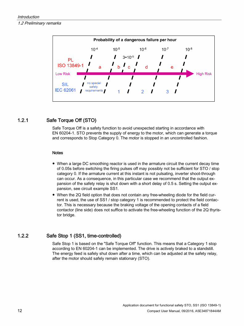
The safety functions listed here are in conformance with:
● Safety Integrity Level (SIL) 2 according to DIN EN 61508
● Category 3 according to DIN EN ISO 13849-1
● Safety of machinery - functional safety according to EN 62061
● Performance Level (PL) d according to DIN EN ISO 13849-1
The safety functions correspond to the functions according to DIN EN 61800-5-2.
This application document explains stop categories 0 and 1.
Introduction 1.2 Preliminary remarks
Application document for functional safety STO, SS1 (ISO 13849-1) 12 Compact User Manual, 09/2016, A5E34871844AM
1.2.1 Safe Torque Off (STO) Safe Torque Off is a safety function to avoid unexpected starting in accordance with EN 60204-1. STO prevents the supply of energy to the motor, which can generate a torque and corresponds to Stop Category 0. The motor is stopped in an uncontrolled fashion.
Notes ● When a large DC smoothing reactor is used in the armature circuit the current decay time
of 0.05s before switching the firing pulses off may possibly not be sufficient for STO / stop category 0. If the armature current at this instant is not pulsating, inverter shoot-through can occur. As a consequence, in this particular case we recommend that the output ex-pansion of the safety relay is shut down with a short delay of 0.5 s. Setting the output ex-pansion, see circuit example SS1.
● When the 2Q field option that does not contain any free-wheeling diode for the field cur-rent is used, the use of SS1 / stop category 1 is recommended to protect the field contac-tor. This is necessary because the braking voltage of the opening contacts of a field contactor (line side) does not suffice to activate the free-wheeling function of the 2Q thyris-tor bridge.
1.2.2 Safe Stop 1 (SS1, time-controlled) Safe Stop 1 is based on the "Safe Torque Off" function. This means that a Category 1 stop according to EN 60204-1 can be implemented. The drive is actively braked to a standstill. The energy feed is safely shut down after a time, which can be adjusted at the safety relay, after the motor should safely remain stationary (STO).
Introduction 1.3 Application overview
Application document for functional safety STO, SS1 (ISO 13849-1) Compact User Manual, 09/2016, A5E34871844AM 13
1.2.3 Using EMERGENCY STOP STO and SS1 are suitable for the EMERGENCY STOP function when the following preconditions are carefully taken into consideration:
The user must evaluate as to whether an immediate shutdown of the energy feed for STO does not result in dangerous states (uncontrolled stopping - STOP category 0 according to EN ISO 13850).
When using SS1, if the line supply fails, the drive can no longer be actively braked - and it must be taken into consideration that the drive only comes to an absolute standstill at a later point in time.
Although actuating the EMERGENCY STOP switch disconnects the energy feed to the drive, for a permanently excited DC motor that is still rotating, a voltage is still present at the armature terminals corresponding to the speed.
With an EMERGENCY OFF function the system is brought into a no voltage condition after switching off in an emergency according to IEC 60204-1. The motor must then come to a complete standstill and the field supply must have been switched off.
EMERGENCY STOP function according to EN ISO 13850: The function of the EMERGENCY STOP equipment must be designed so that after actuating the EMERGENCY STOP device, hazardous motion and operation of the machine are stopped in a suitable fashion without resulting in any additional risks and dangers.
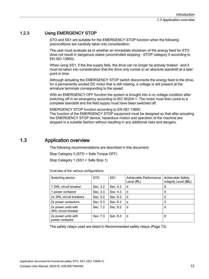
1.3 Application overview The following recommendations are described in this document:
Stop Category 0 (STO = Safe Torque OFF)
Stop Category 1 (SS1 = Safe Stop 1)
Overview of the various configurations
Switching device STO SS1 Achievable Performance Level (PL)
Achievable Safety Integrity Level (SIL)
1 3WL circuit breaker Sec. 3.2 Sec. 4.2 d X 1 power contactor Sec. 3.3 Sec. 4.3 d X 2x 3WL circuit breakers Sec. 5.2 Sec. 6.2 d 2 2s power contactors Sec. 5.3 Sec. 6.3 e 3 2x power units with 3WL circuit breaker
Sec. 7.2 Sec. 8.2 d X
2x power units with power contactor
Sec. 7.3 Sec. 8.3 d X
The safety relays used are listed in Recommended safety relays (Page 73).
Introduction 1.4 Armature circuit with one switching device
Application document for functional safety STO, SS1 (ISO 13849-1) 14 Compact User Manual, 09/2016, A5E34871844AM
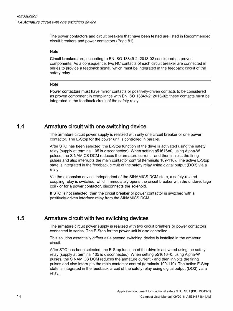
The power contactors and circuit breakers that have been tested are listed in Recommended circuit breakers and power contactors (Page 81).
Note
Circuit breakers are, according to EN ISO 13849-2: 2013-02 considered as proven components. As a consequence, two NC contacts of each circuit breaker are connected in series to provide a feedback signal, which must be integrated in the feedback circuit of the safety relay.
Note
Power contactors must have mirror contacts or positively-driven contacts to be considered as proven component in compliance with EN ISO 13849-2: 2013-02; these contacts must be integrated in the feedback circuit of the safety relay.
1.4 Armature circuit with one switching device The armature circuit power supply is realized with only one circuit breaker or one power contactor. The E-Stop for the power unit is controlled in parallel.
After STO has been selected, the E-Stop function of the drive is activated using the safety relay (supply at terminal 105 is disconnected). When setting p51616=0, using Alpha-W pulses, the SINAMICS DCM reduces the armature current - and then inhibits the firing pulses and also interrupts the main contactor control (terminals 109-110). The active E-Stop state is integrated in the feedback circuit of the safety relay using digital output (DO3) via a relay.
Via the expansion device, independent of the SINAMICS DCM state, a safety-related coupling relay is switched, which immediately opens the circuit breaker with the undervoltage coil - or for a power contactor, disconnects the solenoid.
If STO is not selected, then the circuit breaker or power contactor is switched with a positively-driven interface relay from the SINAMICS DCM.
1.5 Armature circuit with two switching devices The armature circuit power supply is realized with two circuit breakers or power contactors connected in series. The E-Stop for the power unit is also controlled.
This solution essentially differs as a second switching device is installed in the amateur circuit.
After STO has been selected, the E-Stop function of the drive is activated using the safety relay (supply at terminal 105 is disconnected). When setting p51616=0, using Alpha-W pulses, the SINAMICS DCM reduces the armature current - and then inhibits the firing pulses and also interrupts the main contactor control (terminals 109-110). The active E-Stop state is integrated in the feedback circuit of the safety relay using digital output (DO3) via a relay.
Introduction 1.6 Field circuit description
Application document for functional safety STO, SS1 (ISO 13849-1) Compact User Manual, 09/2016, A5E34871844AM 15
Via the expansion device, independent of the SINAMICS DCM state, a safety-related coupling relay is switched, which immediately opens the circuit breaker with the undervoltage coil - or for a power contactor, disconnects the solenoid.
If STO is not selected, then the circuit breakers or power contactors are switched with a positively-driven interface relay from the SINAMICS DCM.
Two switching devices are required to achieve SIL2 according to EN62061 and PL d according to DIN EN ISO 13849-1.
1.6 Field circuit description If a power contactor is used in the field circuit, then this can be optionally switched with the safety function. If the field contactor is to be integrated in the safety function, then the field contactor must be opened and closed with the output expansion of the safety relay using a safety-related interface relay. The positively-driven NC contact of the coupling relay - as well as the mirror contact of the field contactor - must be integrated in the feedback circuit of the safety relay. This version is shown in the circuit examples.
Introduction 1.7 Safety shutdown (E-STOP)
Application document for functional safety STO, SS1 (ISO 13849-1) 16 Compact User Manual, 09/2016, A5E34871844AM
1.7 Safety shutdown (E-STOP)
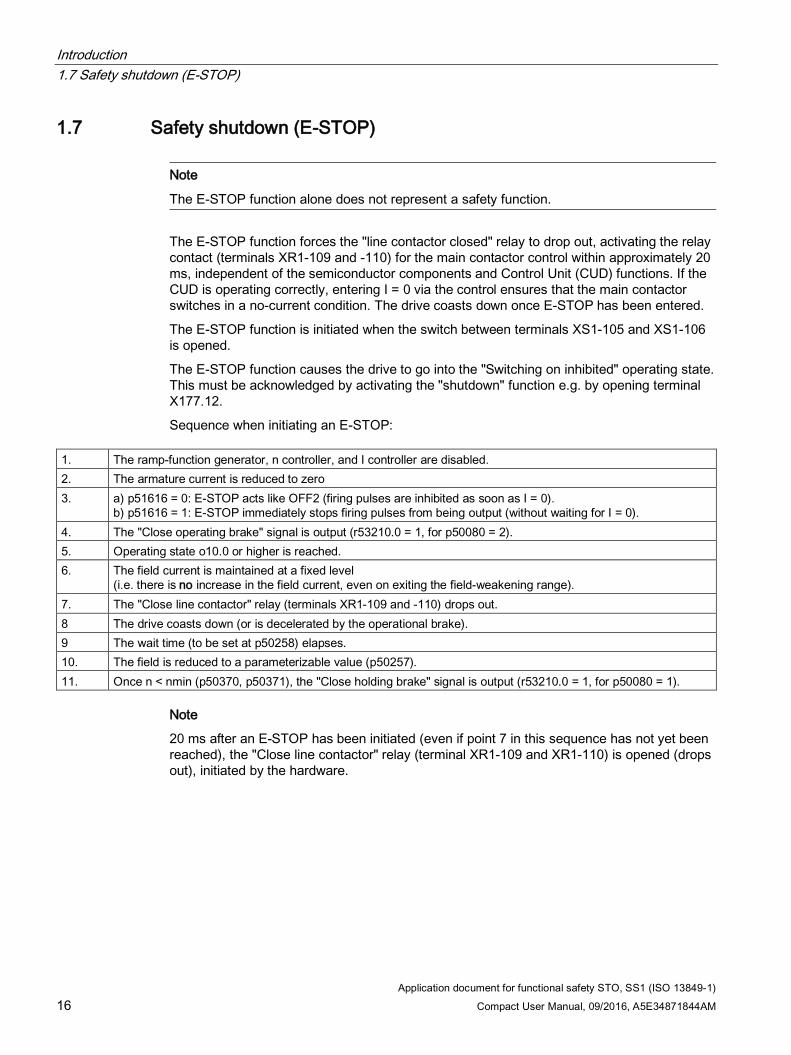
Note
The E-STOP function alone does not represent a safety function.
The E-STOP function forces the "line contactor closed" relay to drop out, activating the relay contact (terminals XR1-109 and -110) for the main contactor control within approximately 20 ms, independent of the semiconductor components and Control Unit (CUD) functions. If the CUD is operating correctly, entering I = 0 via the control ensures that the main contactor switches in a no-current condition. The drive coasts down once E-STOP has been entered.
The E-STOP function is initiated when the switch between terminals XS1-105 and XS1-106 is opened.
The E-STOP function causes the drive to go into the "Switching on inhibited" operating state. This must be acknowledged by activating the "shutdown" function e.g. by opening terminal X177.12.
Sequence when initiating an E-STOP: 1. The ramp-function generator, n controller, and I controller are disabled. 2. The armature current is reduced to zero 3. a) p51616 = 0: E-STOP acts like OFF2 (firing pulses are inhibited as soon as I = 0).
b) p51616 = 1: E-STOP immediately stops firing pulses from being output (without waiting for I = 0). 4. The "Close operating brake" signal is output (r53210.0 = 1, for p50080 = 2). 5. Operating state o10.0 or higher is reached. 6. The field current is maintained at a fixed level
(i.e. there is no increase in the field current, even on exiting the field-weakening range). 7. The "Close line contactor" relay (terminals XR1-109 and -110) drops out. 8 The drive coasts down (or is decelerated by the operational brake). 9 The wait time (to be set at p50258) elapses. 10. The field is reduced to a parameterizable value (p50257). 11. Once n < nmin (p50370, p50371), the "Close holding brake" signal is output (r53210.0 = 1, for p50080 = 1).
Note
20 ms after an E-STOP has been initiated (even if point 7 in this sequence has not yet been reached), the "Close line contactor" relay (terminal XR1-109 and XR1-110) is opened (drops out), initiated by the hardware.
Introduction 1.8 Parameterizing the digital outputs
Application document for functional safety STO, SS1 (ISO 13849-1) Compact User Manual, 09/2016, A5E34871844AM 17
1.8 Parameterizing the digital outputs In order to signal to the safety relay that the drive E-STOP function has been activated, the following parameters must be set at the SINAMICS DC MASTER:
Digital output DO3 at connector X177.22 controls relay KEP. This serves as feedback signal contact for the E-STOP path. The function of DO3 (connector X177.22) is defined using parameter p50774: p50774 = (63) r53100.0
Digital output DO2 at connector X177.21 controls, via relay K DO2F, the field contactor. The function of DO2 (connector X177.21) is defined using parameter p50773. The setting of p50773 is dependent on the setting of parameter p50082:
p50082 = 0 (no field) p50773 = 0 p50082 = 1 (field is also switched with the armature contactor) p50773 = (63) r53082.0 p50082 = 2 (standstill field at ≥ o7.0) p50773 = 1 p50082 = 3 (field is permanently switched on) p50773 = 1 p50082 = 4 (field is also switched with the auxiliaries ON sig-
nal) p50773 = (63) r53210.2
p50082 = 21 (external field power unit, otherwise, as for setting 1)
p50773 = (63) r53082.0
p50082 = 22 (external field power unit, otherwise, as for setting 3)
p50773 = 1
p50082 = 23 (external field power unit, otherwise, as for setting 3)
p50773 = 1
p50082 = 24 (external field power unit, otherwise, as for setting 4)
p50773 = (63) r53210.2
Note (63) signifies: "from own drive object" r53100.0 is E-Stop state (1 = no E-Stop, 0 = E-Stop) r53082.0 is CLOSE armature contactor r53210.2 is auxiliaries ON
Note The maximum 100 mA current rating of the digital outputs must be carefully observed.
Introduction 1.9 Parameterizing the digital input for SS1 OFF3
Application document for functional safety STO, SS1 (ISO 13849-1) 18 Compact User Manual, 09/2016, A5E34871844AM
1.9 Parameterizing the digital input for SS1 OFF3 Digital input DI/DO 4 (terminal X177.15 on the CUD electronics module) of the SINAMICS DC MASTER must be used for the SS1 function. This digital input must be parameterized so that signal OFF3 (fast stop) is controlled in all of the command data sets (CDS) used
Setting p849 (OFF3) p53010[8] (DI/DO 4)
Setting p50296 (OFF3 down ramp) e.g. 5 seconds
Note For setting p50269=0 (OFF3 ramp down time), the drive brakes at the current limit. The actual ramp-down time is influenced by the driving forces of the mechanical system. The safety relay delay should be set longer than the actual ramp-down time.
Introduction 1.10 Abbreviations and circuit diagram symbols
Application document for functional safety STO, SS1 (ISO 13849-1) Compact User Manual, 09/2016, A5E34871844AM 19
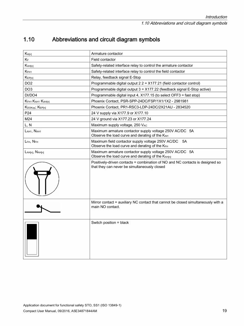
1.10 Abbreviations and circuit diagram symbols KA[n] Armature contactor KF Field contactor KAH[n] Safety-related interface relay to control the armature contactor KFH1 Safety-related interface relay to control the field contactor KEP[n] Relay, feedback signal E-Stop DO2 Programmable digital output 2 2 = X177.21 (field contactor control) DO3 Programmable digital output 3 = X177.22 (feedback signal E-Stop active) DI/DO4 Programmable digital input 4, X177.15 (to select OFF3 = fast stop) KFH1 KAH1 KAH[n] Phoenix Contact, PSR-SPP-24DC/FSP/1X1/1X2 - 2981981 KDOKop; KEP[n] Phoenix Contact, PR1-RSC3-LDP-24DC/2X21AU - 2834520 P24 24 V supply via X177.9 or X177.10 M24 24 V ground via X177.23 or X177.24 L, N Maximum supply voltage, 250 VAC LAH1, NAH1 Maximum armature contactor supply voltage 250V AC/DC 5A
Observe the load curve and derating of the KAH LFH, NFH Maximum field contactor supply voltage 250V AC/DC 5A
Observe the load curve and derating of the KFH LAH[n], NAH[n] Maximum armature contactor supply voltage 250V AC/DC 5A
Observe the load curve and derating of the KAH[n]
Positively-driven contacts = combination of NO and NC contacts is designed so that they can never be simultaneously closed
Mirror contact = auxiliary NC contact that cannot be closed simultaneously with a main NO contact.
Switch position = black
Introduction 1.10 Abbreviations and circuit diagram symbols
Application document for functional safety STO, SS1 (ISO 13849-1) 20 Compact User Manual, 09/2016, A5E34871844AM
Application document for functional safety STO, SS1 (ISO 13849-1) Compact User Manual, 09/2016, A5E34871844AM 21
Principle of the dual channel architecture 2
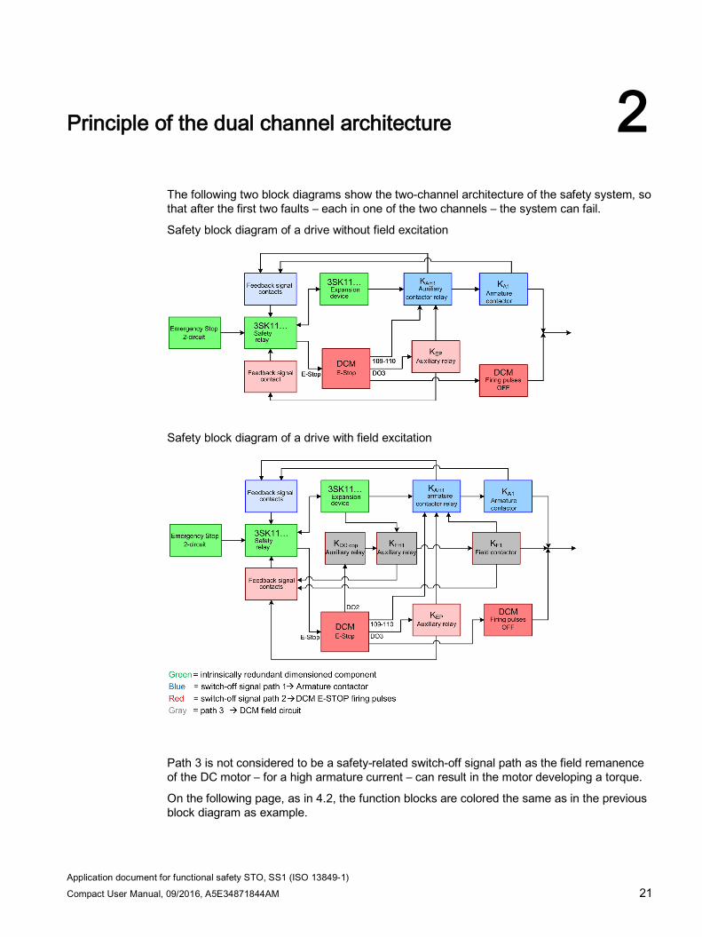
The following two block diagrams show the two-channel architecture of the safety system, so that after the first two faults – each in one of the two channels – the system can fail.
Safety block diagram of a drive without field excitation
Safety block diagram of a drive with field excitation
Path 3 is not considered to be a safety-related switch-off signal path as the field remanence of the DC motor – for a high armature current – can result in the motor developing a torque.
On the following page, as in 4.2, the function blocks are colored the same as in the previous block diagram as example.
Principle of the dual channel architecture
Application document for functional safety STO, SS1 (ISO 13849-1) 22 Compact User Manual, 09/2016, A5E34871844AM
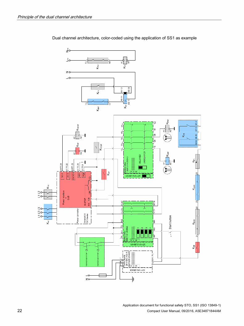
Dual channel architecture, color-coded using the application of SS1 as example
Application document for functional safety STO, SS1 (ISO 13849-1) Compact User Manual, 09/2016, A5E34871844AM 23
STO stop Category 0 with one switching device 3 3.1 Description
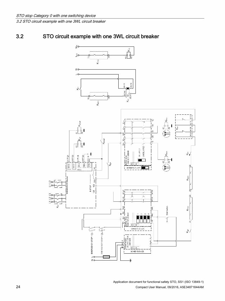
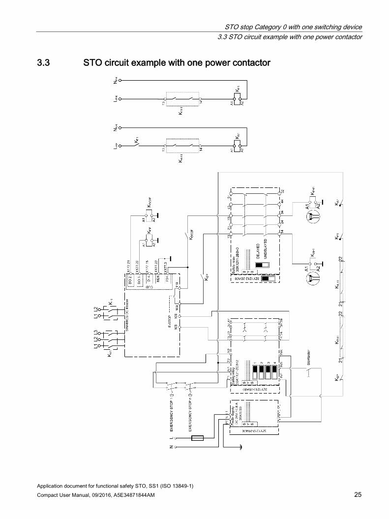
When selecting the safety function (actuating the Emergency Stop pushbutton), the instantaneous NO contacts are immediately opened in the 3SK1122-2CB41 safety relay. As a consequence, the E-Stop function is initiated at the SINAMICS DCM. The SINAMICS DCM reduces the armature current, inhibits the firing pulses and opens the armature contactor. The "E-Stop active" signal must be integrated in the feedback circuit of the safety relay via a coupling relay at digital output DO3 (X177.22). At the same time when the NO contacts of the safety relay open, the safety-related output expansion 3SK1211-2BB40 is shut down via the internal communication of the 3SK safety relay; as a consequence, the safety-related coupling relays to control the armature and field circuits are opened.
The motor current therefore goes to zero and in turn, the motor torque also goes to zero. The motor coasts down.
In the circuit examples, the energy feed to the field power units as well as to the armature circuit is interrupted. Controlling the field contactor is optional. However, in this case, the motor cannot be considered to be in a no-voltage condition.
STO stop Category 0 with one switching device 3.2 STO circuit example with one 3WL circuit breaker
Application document for functional safety STO, SS1 (ISO 13849-1) 24 Compact User Manual, 09/2016, A5E34871844AM
3.2 STO circuit example with one 3WL circuit breaker
STO stop Category 0 with one switching device 3.3 STO circuit example with one power contactor
Application document for functional safety STO, SS1 (ISO 13849-1) Compact User Manual, 09/2016, A5E34871844AM 25
3.3 STO circuit example with one power contactor
STO stop Category 0 with one switching device 3.3 STO circuit example with one power contactor
Application document for functional safety STO, SS1 (ISO 13849-1) 26 Compact User Manual, 09/2016, A5E34871844AM
Application document for functional safety STO, SS1 (ISO 13849-1) Compact User Manual, 09/2016, A5E34871844AM 27
SS1 stop Category 1 with one switching device 4 4.1 Description
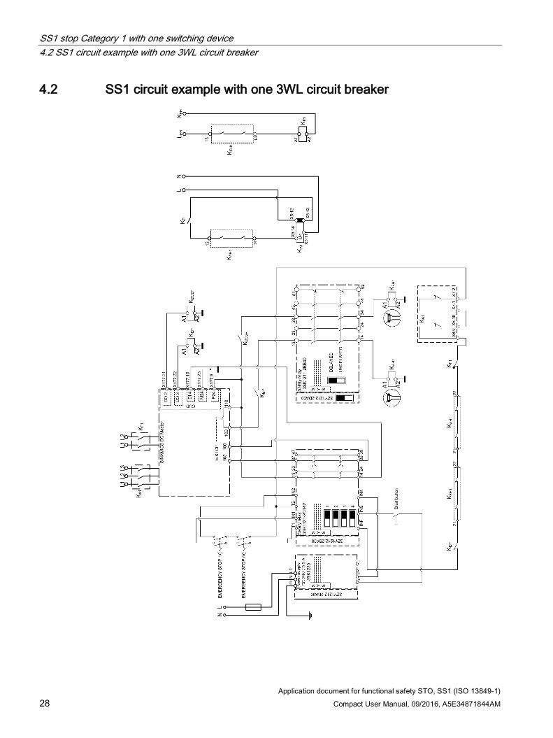
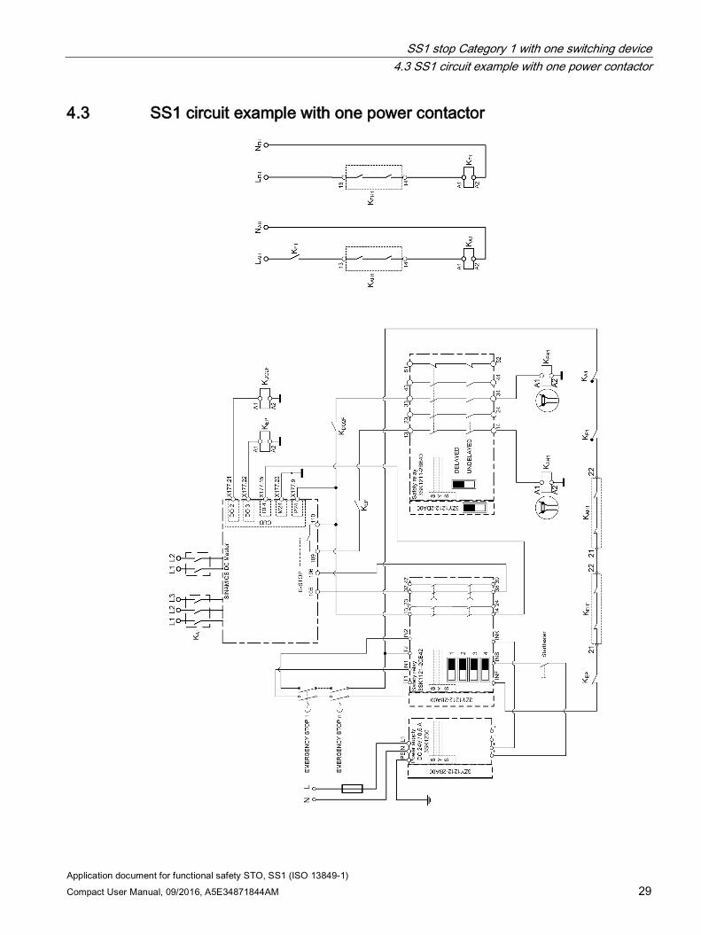
When selecting the safety function (actuating the EMERGENCY STOP pushbutton), the instantaneous NO contacts are immediately opened in the 3SK1122-2CB4x1 safety relay. As a consequence, at the SINAMICS DCM, the OFF3 function (fast stop) is initiated via the programmable digital input DI/DO4 (X177.15). The drive is braked along a ramp that can be adjusted using p50269. The down ramp is not monitored. As soon as the SINAMICS DCM identifies that the motor is at a standstill, the firing pulses are inhibited and the power disconnected.
Independent of the down ramp that has been adjusted, after the time set at the safety relay, the delayed contact of the safety relay is opened. These contacts initiate the E-Stop function at the SINAMICS DCM. The SINAMICS DCM reduces the armature current, inhibits the firing pulses and opens the armature contactor. The "E-Stop active" signal must be integrated in the feedback circuit of the safety relay via a coupling relay at digital output DO3 (X177.22). At the same time that the E-Stop function is selected, the NO contacts of the safety-related output expansion 3SK1211-2BB40 open via the internal communication of the 3SK safety relays; as a consequence, the safety-related interface relays to control the armature and field circuits are opened.
The motor current therefore goes to zero and in turn, the motor torque also goes to zero. The motor coasts down if a speed of zero has still not been reached.
The drive system can only be considered to be in a torque-free state after the delay time has expired and the power switching devices opened.
In the circuit examples, the energy feed to the field power units as well as to the armature circuit is interrupted. Controlling the field contactor is optional. However, in this case, the motor cannot be considered to be in a no-voltage condition.
Note
For setting p50269=0 (OFF3 ramp down time), the drive brakes at the current limit. The actual ramp-down time is influenced by the driving forces of the mechanical system. The safety relay delay should be set longer than the actual ramp-down time.
1 (x) order code for the time delay: 1 = 0.05 ... 3 s 2 = 0.5 ... 30 s 4 = 5 ... 300 s
SS1 stop Category 1 with one switching device 4.2 SS1 circuit example with one 3WL circuit breaker
Application document for functional safety STO, SS1 (ISO 13849-1) 28 Compact User Manual, 09/2016, A5E34871844AM
4.2 SS1 circuit example with one 3WL circuit breaker
SS1 stop Category 1 with one switching device 4.3 SS1 circuit example with one power contactor
Application document for functional safety STO, SS1 (ISO 13849-1) Compact User Manual, 09/2016, A5E34871844AM 29
4.3 SS1 circuit example with one power contactor
SS1 stop Category 1 with one switching device 4.3 SS1 circuit example with one power contactor
Application document for functional safety STO, SS1 (ISO 13849-1) 30 Compact User Manual, 09/2016, A5E34871844AM
Application document for functional safety STO, SS1 (ISO 13849-1) Compact User Manual, 09/2016, A5E34871844AM 31
STO, two switching devices in series 5 5.1 Description
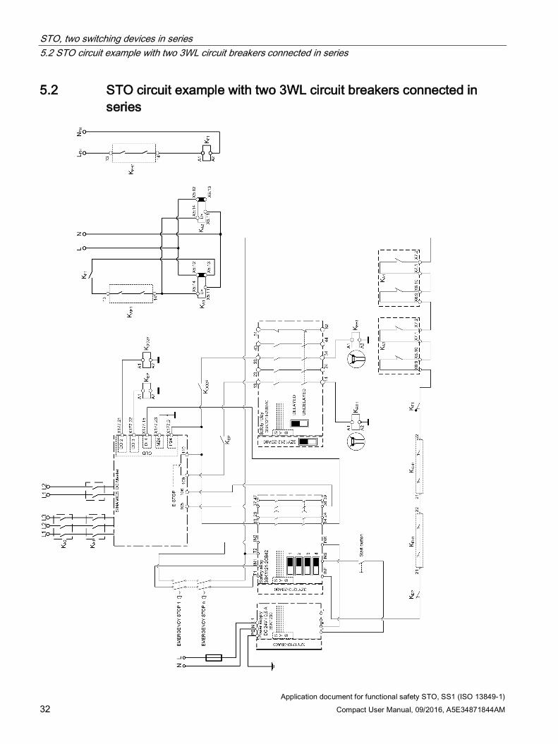
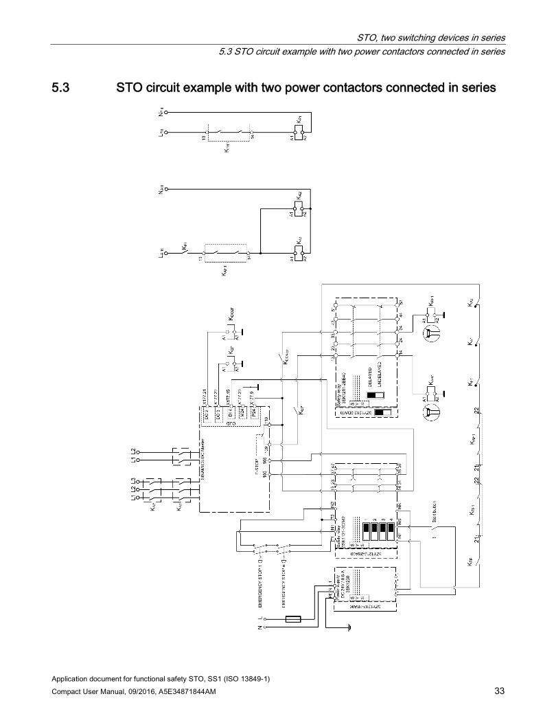
When selecting the safety function (actuating the EMERGENCY STOP pushbutton), the instantaneous NO contacts are immediately opened in the 3SK1122-2CB41 safety relay, which immediately causes the E-Stop function to be initiated at the SINAMICS DCM. The SINAMICS DCM reduces the armature current, inhibits the firing pulses and opens the armature contactor. The "E-Stop active" signal must be integrated in the feedback circuit of the safety relay via a coupling relay at digital output DO3 (X177.22). At the same time when the NO contacts of the safety relay open, the safety-related output expansion 3SK1211-2BB40 is shut down via the internal communication of the 3SK safety relays; as a consequence, the safety-related coupling relays to control the armature and field circuits are opened.
The motor current therefore goes to zero and in turn, the motor torque also goes to zero. The motor coasts down.
In the circuit examples, the energy feed to the field power units as well as to the armature circuit is interrupted. Two power switching devices connected in series are used in the armature circuit. Controlling the field contactor is optional. However, in this case, the motor cannot be considered to be in a no-voltage condition.
STO, two switching devices in series 5.2 STO circuit example with two 3WL circuit breakers connected in series
Application document for functional safety STO, SS1 (ISO 13849-1) 32 Compact User Manual, 09/2016, A5E34871844AM
5.2 STO circuit example with two 3WL circuit breakers connected in series
STO, two switching devices in series 5.3 STO circuit example with two power contactors connected in series
Application document for functional safety STO, SS1 (ISO 13849-1) Compact User Manual, 09/2016, A5E34871844AM 33
5.3 STO circuit example with two power contactors connected in series

STO, two switching devices in series 5.3 STO circuit example with two power contactors connected in series
Application document for functional safety STO, SS1 (ISO 13849-1) 34 Compact User Manual, 09/2016, A5E34871844AM
Application document for functional safety STO, SS1 (ISO 13849-1) Compact User Manual, 09/2016, A5E34871844AM 35
SS1, two switching devices connected in series 6 6.1 Description
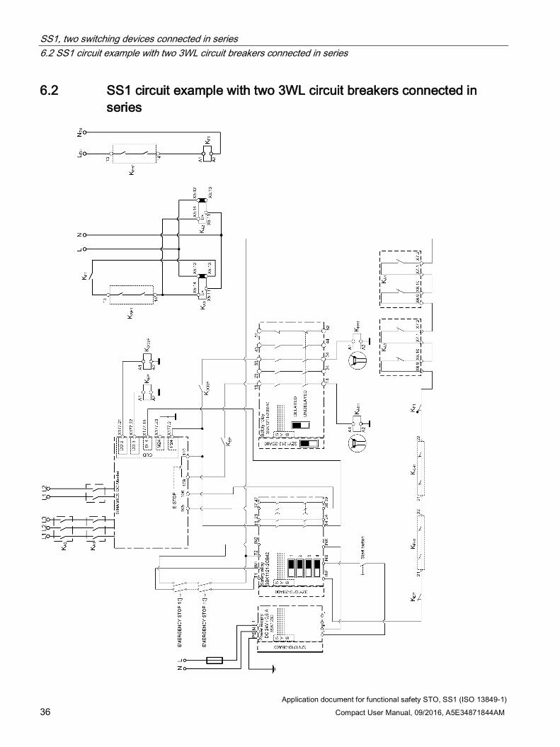
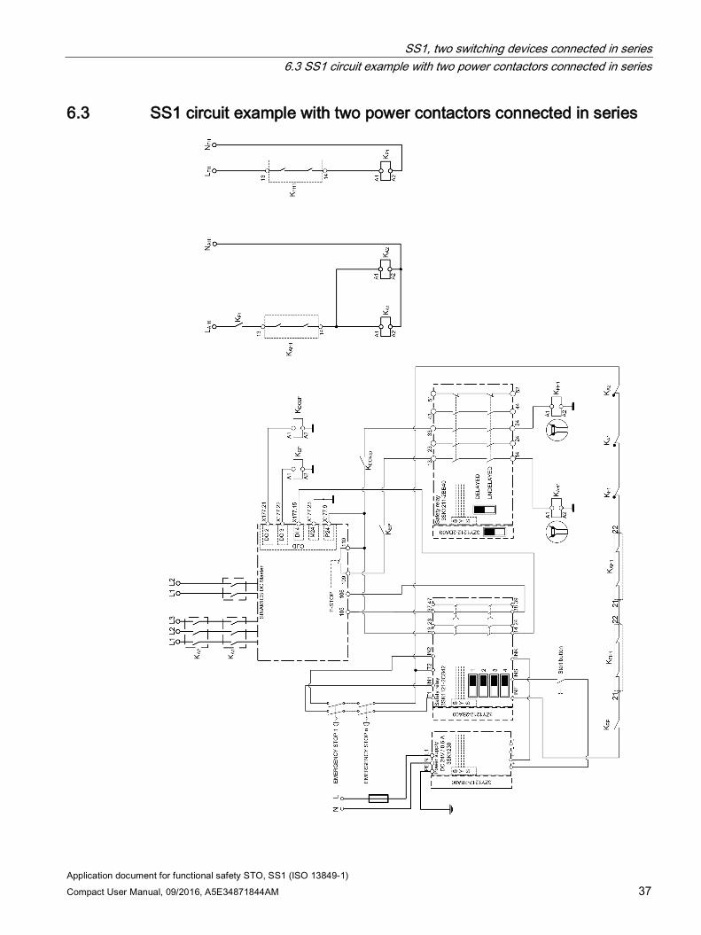
When selecting the safety function (actuating the mushroom pushbutton), the instantaneous NO contacts are immediately opened in the 3SK1122-2CB4x1 safety relay. As a consequence, at the SINAMICS DCM, the OFF3 function (fast stop) is initiated via the programmable digital input DIO4 (X177.15). The drive is braked along a ramp that can be adjusted using p50269. The down ramp is not monitored. As soon as the SINAMICS DCM identifies that the motor is at a standstill (speed of 0), the firing pulses are inhibited and the power disconnected.
Independent of the down ramp that has been adjusted, after the time set at the safety relay, the delayed contact of the safety relay is opened. These contacts initiate the E-Stop function at the SINAMICS DCM. The SINAMICS DCM reduces the armature current, inhibits the firing pulses and opens the armature contactor. The "E-Stop active" signal must be integrated in the feedback circuit of the safety relay via an interface relay at digital output DO3 (X177.22). At the same time that the E-Stop function is selected, the NO contacts of the safety-related output expansion 3SK1211-2BB40 open via the internal communication of the 3SK safety relays; as a consequence, the safety-related coupling relays to control the armature and field circuits are opened.
The motor current therefore goes to zero and in turn, the motor torque also goes to zero. The motor coasts down if a speed of zero has still not been reached.
The drive system can only be considered to be in a torque-free state after the delay time has expired and the power switching devices opened.
In the circuit examples, the energy feed to the field power units as well as to the armature circuit is interrupted. Two power switching devices connected in series are used in the armature circuit. Controlling the field contactor is optional. However, in this case, the motor cannot be considered to be in a no-voltage condition.
Note
For setting p50269=0 (OFF3 ramp down time), the drive brakes at the current limit. The actual ramp-down time is influenced by the driving forces of the mechanical system. The safety relay delay should be set longer than the actual ramp-down time.
1 (x) order code for the time delay: 1 = 0.05 ... 3 s 2 = 0.5 ... 30 s 4 = 5 ... 300 s
SS1, two switching devices connected in series 6.2 SS1 circuit example with two 3WL circuit breakers connected in series
Application document for functional safety STO, SS1 (ISO 13849-1) 36 Compact User Manual, 09/2016, A5E34871844AM
6.2 SS1 circuit example with two 3WL circuit breakers connected in series
SS1, two switching devices connected in series 6.3 SS1 circuit example with two power contactors connected in series
Application document for functional safety STO, SS1 (ISO 13849-1) Compact User Manual, 09/2016, A5E34871844AM 37
6.3 SS1 circuit example with two power contactors connected in series
SS1, two switching devices connected in series 6.3 SS1 circuit example with two power contactors connected in series
Application document for functional safety STO, SS1 (ISO 13849-1) 38 Compact User Manual, 09/2016, A5E34871844AM
Application document for functional safety STO, SS1 (ISO 13849-1) Compact User Manual, 09/2016, A5E34871844AM 39
STO stop Category 0, several power units 7 7.1 Description
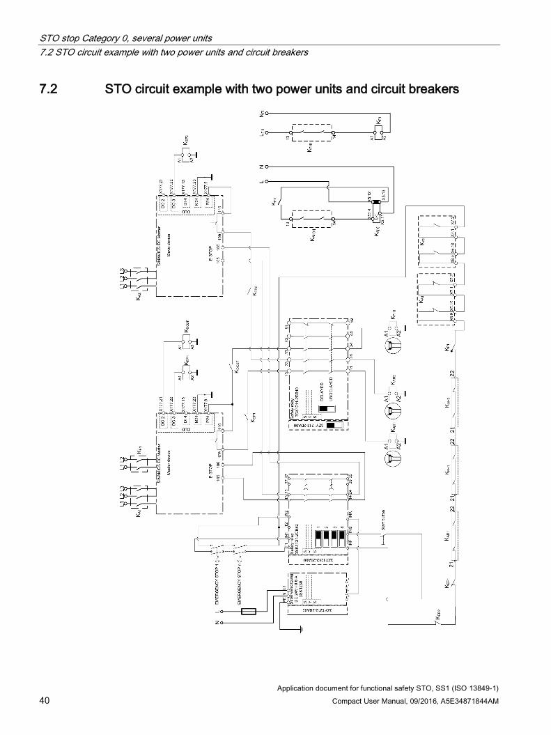
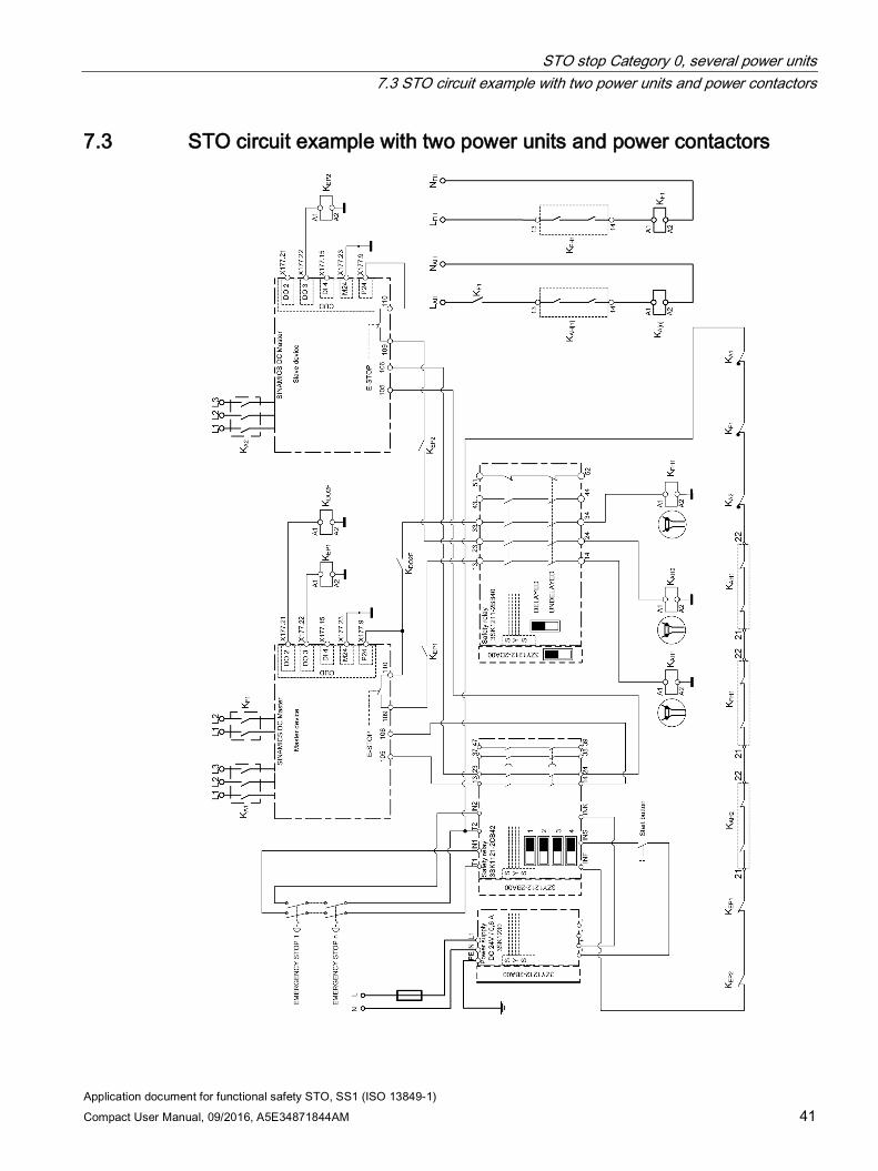
When selecting the safety function (actuating the EMERGENCY STOP mushroom pushbutton), the instantaneous NO contacts are immediately opened in the 3SK1122-2CB41 safety relay, which immediately causes the E-Stop function to be initiated at all SINAMICS DCM connected in parallel/series. The SINAMICS DCMs reduces the armature current, inhibits the firing pulses and opens the armature contactor. The "E-Stop active" signal from every device must be integrated in the feedback circuit of the safety relay via an interface relay at digital output DO3 (X177.22). At the same time when the NO contacts of the safety relay open, the safety-related output expansion 3SK1211-2BB40 is shut down via the internal communication of the 3SK safety relays; as a consequence, the safety-related coupling relays to control the armature and field circuits are opened.
The motor current therefore goes to zero and in turn, the motor torque also goes to zero. The motor coasts down.
Up to 6 SINAMICS DCM units can be connected in parallel or series. For all units, the E-Stop terminals - as well as the armature contacts - must be integrated via safety relays. This is realized with the additional safety-related output expansions 3SK1211-2BB40.
In the circuit examples, the energy feed to the field power units as well as to the armature circuit is interrupted. Controlling the field contactor is optional. However, in this case, the motor cannot be considered to be in a no-voltage condition.
STO stop Category 0, several power units 7.2 STO circuit example with two power units and circuit breakers
Application document for functional safety STO, SS1 (ISO 13849-1) 40 Compact User Manual, 09/2016, A5E34871844AM
7.2 STO circuit example with two power units and circuit breakers
STO stop Category 0, several power units 7.3 STO circuit example with two power units and power contactors
Application document for functional safety STO, SS1 (ISO 13849-1) Compact User Manual, 09/2016, A5E34871844AM 41
7.3 STO circuit example with two power units and power contactors
STO stop Category 0, several power units 7.3 STO circuit example with two power units and power contactors
Application document for functional safety STO, SS1 (ISO 13849-1) 42 Compact User Manual, 09/2016, A5E34871844AM
Application document for functional safety STO, SS1 (ISO 13849-1) Compact User Manual, 09/2016, A5E34871844AM 43
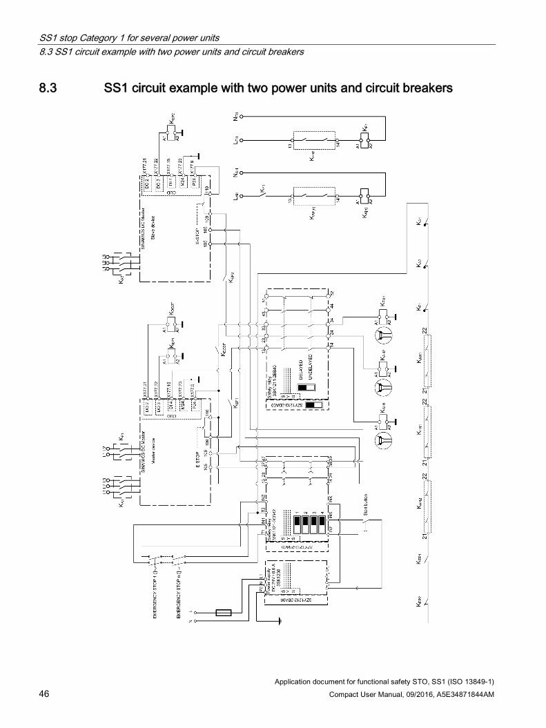
SS1 stop Category 1 for several power units 8 8.1 Description
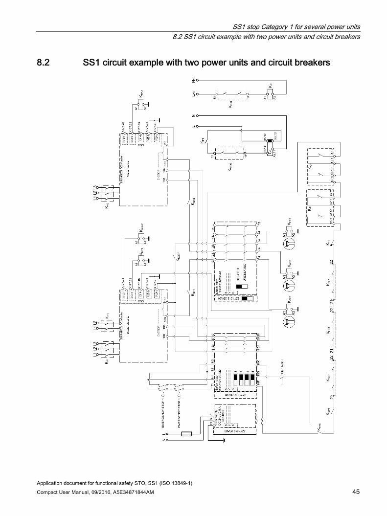
When selecting the safety function (actuating the EMERGENCY STOP mushroom pushbutton), the instantaneous NO contacts are immediately opened in the 3SK1122-2CB4x1 safety relay, which immediately causes the OFF3 function (fast stop) to be initiated at the SINAMICS DCM "Master Unit" via the programmable digital input DIO4 (X177.15). The drive is braked along a ramp that can be adjusted using p50269. The down ramp is not monitored. As soon as the SINAMICS DCM identifies that the motor is at a standstill (speed of 0), the firing pulses are inhibited and the power disconnected.
Independent of the down ramp that has been adjusted, after the time set at the safety relay, the delayed contact of the safety relay is opened. These contacts initiate the E-Stop function at all of the SINAMICS DCM units. The SINAMICS DCM units reduce the armature current, inhibit the firing pulses and open the armature contactor. The "E-Stop active" signal must be integrated in the feedback circuit of the safety relay via a coupling relay at digital output DO3 (X177.22). At the same time when the NO contacts of the safety relay open, the safety-related output expansion 3SK1211-2BB40 is shut down via the internal communication of the 3SK safety relays; as a consequence, the safety-related coupling relays to control the armature and field circuits are opened.
The motor current therefore goes to zero and in turn, the motor torque also goes to zero. If zero speed has still not been reached, then the motor coasts down. The drive system can only be considered to be in a torque-free state after the delay time has expired and the power switching devices opened.
Up to 6 SINAMICS DCM units can be connected in parallel or series. For all units, the E-Stop terminals - as well as the armature contacts - must be integrated via safety relays. This is realized with the additional safety-related output expansions 3SK1211-2BB40.
In the circuit examples, the energy feed to the field power units as well as to the armature circuit is interrupted. Controlling the field contactor is optional. However, in this case, the motor cannot be considered to be in a no-voltage condition.
Note
For setting p50269=0 (OFF3 ramp down time), the drive brakes at the current limit. The actual ramp-down time is influenced by the driving forces of the mechanical system. The safety relay delay should be set longer than the actual ramp-down time.
1 (x) order code for the time delay: 1 = 0.05 ... 3 s
SS1 stop Category 1 for several power units 8.1 Description
Application document for functional safety STO, SS1 (ISO 13849-1) 44 Compact User Manual, 09/2016, A5E34871844AM
2 = 0.5 ... 30 s 4 = 5 ... 300 s
SS1 stop Category 1 for several power units 8.2 SS1 circuit example with two power units and circuit breakers
Application document for functional safety STO, SS1 (ISO 13849-1) Compact User Manual, 09/2016, A5E34871844AM 45
8.2 SS1 circuit example with two power units and circuit breakers
SS1 stop Category 1 for several power units 8.3 SS1 circuit example with two power units and circuit breakers
Application document for functional safety STO, SS1 (ISO 13849-1) 46 Compact User Manual, 09/2016, A5E34871844AM
8.3 SS1 circuit example with two power units and circuit breakers
Application document for functional safety STO, SS1 (ISO 13849-1) Compact User Manual, 09/2016, A5E34871844AM 47
Evaluating the safety functions according to EN ISO 13849 when using one switching device 9
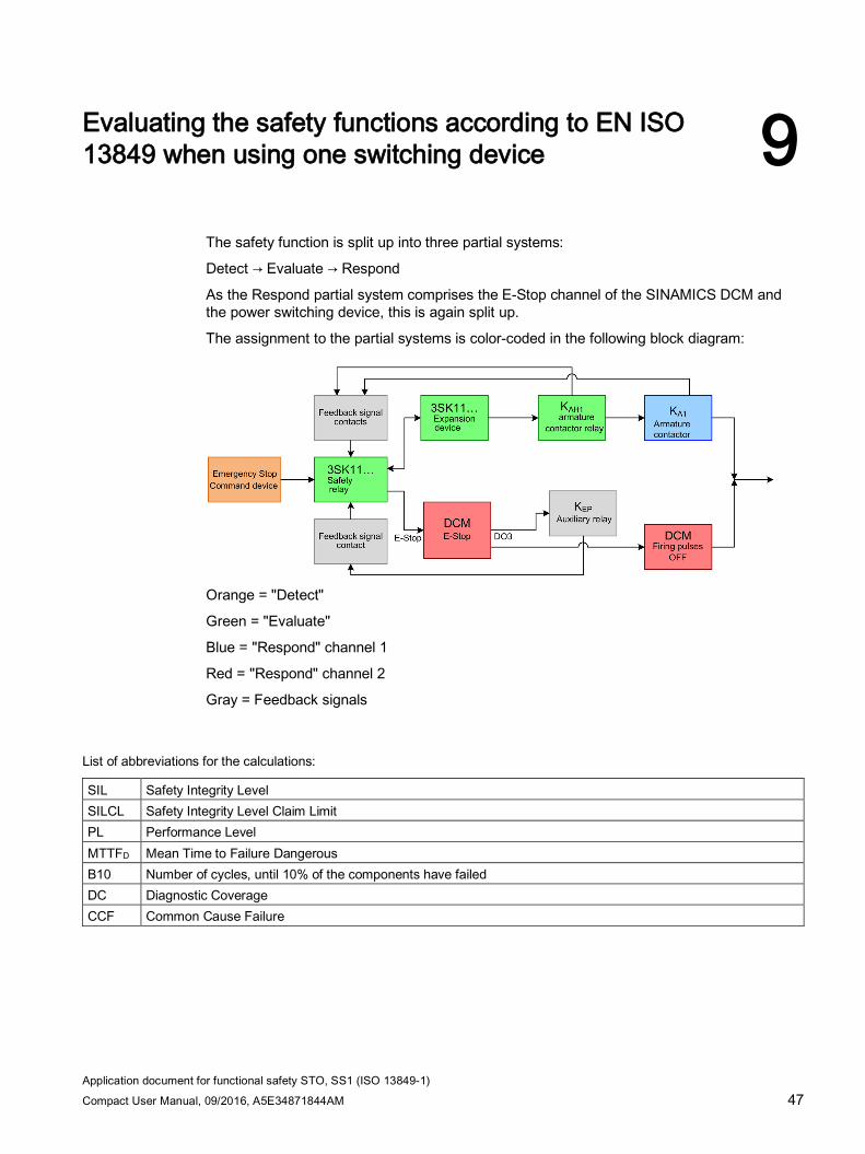
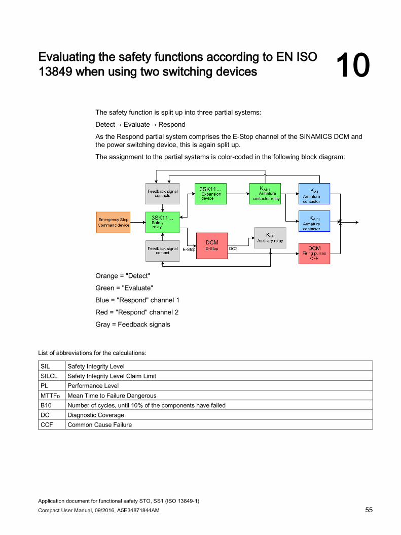
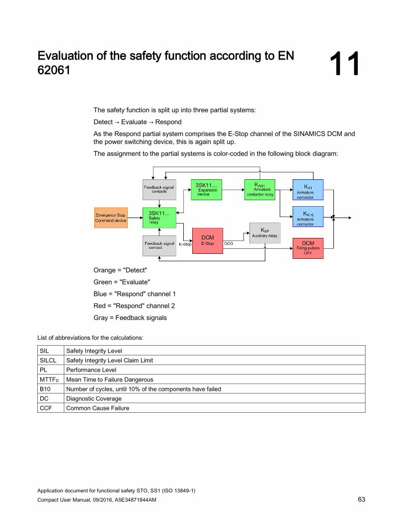
The safety function is split up into three partial systems:
Detect → Evaluate → Respond
As the Respond partial system comprises the E-Stop channel of the SINAMICS DCM and the power switching device, this is again split up.
The assignment to the partial systems is color-coded in the following block diagram:
Orange = "Detect"
Green = "Evaluate"
Blue = "Respond" channel 1
Red = "Respond" channel 2
Gray = Feedback signals
List of abbreviations for the calculations:
SIL Safety Integrity Level SILCL Safety Integrity Level Claim Limit PL Performance Level MTTFD Mean Time to Failure Dangerous B10 Number of cycles, until 10% of the components have failed DC Diagnostic Coverage CCF Common Cause Failure
Evaluating the safety functions according to EN ISO 13849 when using one switching device 9.1 Evaluation of "Detect"
Application document for functional safety STO, SS1 (ISO 13849-1) 48 Compact User Manual, 09/2016, A5E34871844AM
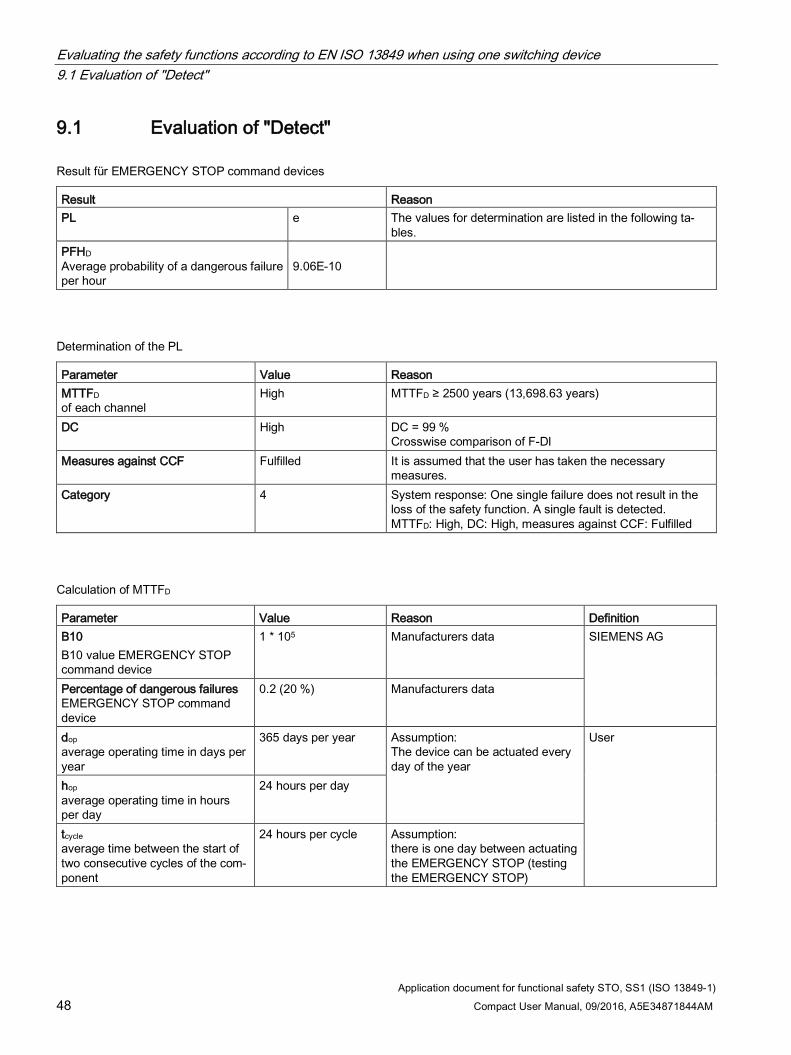
9.1 Evaluation of "Detect"
Result für EMERGENCY STOP command devices
Result Reason PL e The values for determination are listed in the following ta-
bles. PFHD Average probability of a dangerous failure per hour
9.06E-10
Determination of the PL
Parameter Value Reason MTTFD of each channel
High MTTFD ≥ 2500 years (13,698.63 years)
DC High DC = 99 % Crosswise comparison of F-DI
Measures against CCF Fulfilled It is assumed that the user has taken the necessary measures.
Category 4 System response: One single failure does not result in the loss of the safety function. A single fault is detected. MTTFD: High, DC: High, measures against CCF: Fulfilled
Calculation of MTTFD
Parameter Value Reason Definition B10 B10 value EMERGENCY STOP command device
1 * 105 Manufacturers data SIEMENS AG
Percentage of dangerous failures EMERGENCY STOP command device
0.2 (20 %) Manufacturers data
dop average operating time in days per year
365 days per year Assumption: The device can be actuated every day of the year
User
hop average operating time in hours per day
24 hours per day
tcycle average time between the start of two consecutive cycles of the com-ponent
24 hours per cycle Assumption: there is one day between actuating the EMERGENCY STOP (testing the EMERGENCY STOP)

Evaluating the safety functions according to EN ISO 13849 when using one switching device 9.2 Evaluation of "Evaluate"
Application document for functional safety STO, SS1 (ISO 13849-1) Compact User Manual, 09/2016, A5E34871844AM 49
9.2 Evaluation of "Evaluate"
Result
Result Reason PL e
Derived from the evaluation according to IEC 62061
PFHD Average probability of a dangerous failure per hour
5.42 E-09
Parameter Component Value Definition PFHD (basic device advanced) 3SK1121 basic device 3.7 E-09 SIEMENS AG PFHD (output expansion) 3SK1211 output ex-
pansion 1.7 E-09
PFHD (coupling relay KAH[n]) Article number Phoenix 2981981
2.02 E-11 Phoenix Contact
Evaluating the safety functions according to EN ISO 13849 when using one switching device 9.3 Evaluation of "Respond"
Application document for functional safety STO, SS1 (ISO 13849-1) 50 Compact User Manual, 09/2016, A5E34871844AM
9.3 Evaluation of "Respond"
9.3.1 Evaluation of "Respond" with one power switching device
9.3.1.1 Evaluation of an 3WL circuit breaker
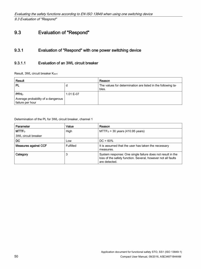
Result, 3WL circuit breaker KAH1
Result Reason PL d The values for determination are listed in the following ta-
bles. PFHD Average probability of a dangerous failure per hour
1.01 E-07
Determination of the PL for 3WL circuit breaker, channel 1
Parameter Value Reason MTTFD 3WL circuit breaker
High MTTFD > 30 years (410.95 years)
DC Low DC = 60% Measures against CCF Fulfilled It is assumed that the user has taken the necessary
measures. Category 3 System response: One single failure does not result in the
loss of the safety function. Several, however not all faults are detected.
Evaluating the safety functions according to EN ISO 13849 when using one switching device 9.3 Evaluation of "Respond"
Application document for functional safety STO, SS1 (ISO 13849-1) Compact User Manual, 09/2016, A5E34871844AM 51
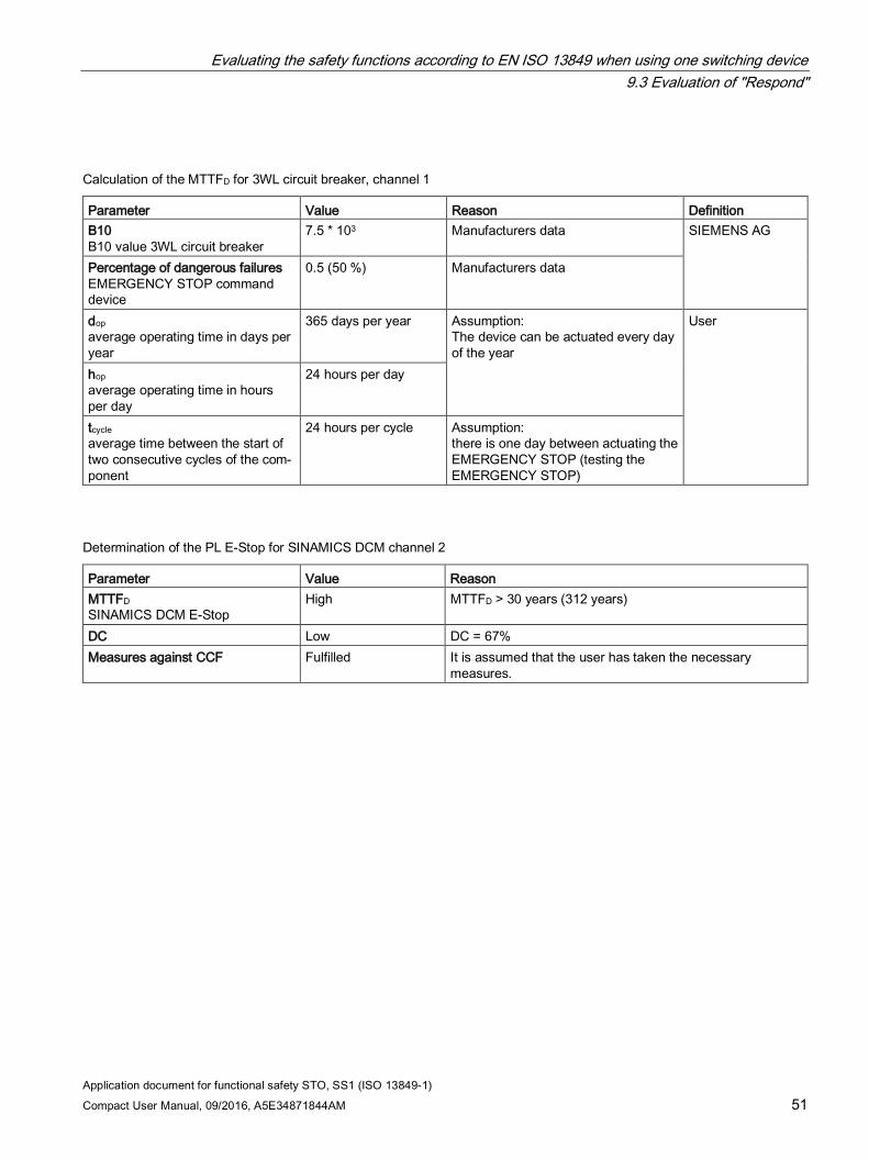
Calculation of the MTTFD for 3WL circuit breaker, channel 1
Parameter Value Reason Definition B10 B10 value 3WL circuit breaker
7.5 * 103 Manufacturers data SIEMENS AG
Percentage of dangerous failures EMERGENCY STOP command device
0.5 (50 %) Manufacturers data
dop average operating time in days per year
365 days per year Assumption: The device can be actuated every day of the year
User
hop average operating time in hours per day
24 hours per day
tcycle average time between the start of two consecutive cycles of the com-ponent
24 hours per cycle Assumption: there is one day between actuating the EMERGENCY STOP (testing the EMERGENCY STOP)
Determination of the PL E-Stop for SINAMICS DCM channel 2
Parameter Value Reason MTTFD SINAMICS DCM E-Stop
High MTTFD > 30 years (312 years)
DC Low DC = 67% Measures against CCF Fulfilled It is assumed that the user has taken the necessary
measures.
Evaluating the safety functions according to EN ISO 13849 when using one switching device 9.3 Evaluation of "Respond"
Application document for functional safety STO, SS1 (ISO 13849-1) 52 Compact User Manual, 09/2016, A5E34871844AM
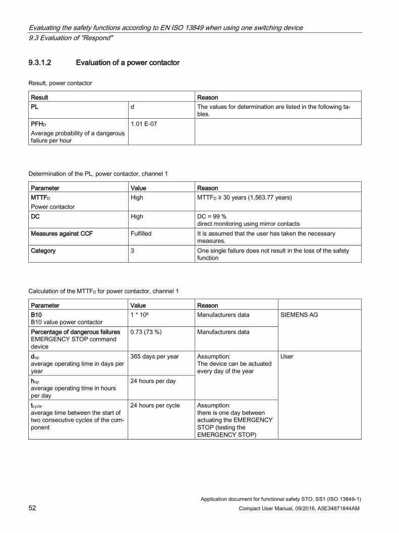
9.3.1.2 Evaluation of a power contactor
Result, power contactor
Result Reason PL d The values for determination are listed in the following ta-
bles. PFHD Average probability of a dangerous failure per hour
1.01 E-07
Determination of the PL, power contactor, channel 1
Parameter Value Reason MTTFD Power contactor
High MTTFD ≥ 30 years (1,563.77 years)
DC High DC = 99 % direct monitoring using mirror contacts
Measures against CCF Fulfilled It is assumed that the user has taken the necessary measures.
Category 3 One single failure does not result in the loss of the safety function
Calculation of the MTTFD for power contactor, channel 1
Parameter Value Reason B10 B10 value power contactor
1 * 106 Manufacturers data SIEMENS AG
Percentage of dangerous failures EMERGENCY STOP command device
0.73 (73 %) Manufacturers data
dop average operating time in days per year
365 days per year Assumption: The device can be actuated every day of the year
User
hop average operating time in hours per day
24 hours per day
tcycle average time between the start of two consecutive cycles of the com-ponent
24 hours per cycle Assumption: there is one day between actuating the EMERGENCY STOP (testing the EMERGENCY STOP)
Evaluating the safety functions according to EN ISO 13849 when using one switching device 9.4 Result when using a 3WL circuit breaker
Application document for functional safety STO, SS1 (ISO 13849-1) Compact User Manual, 09/2016, A5E34871844AM 53
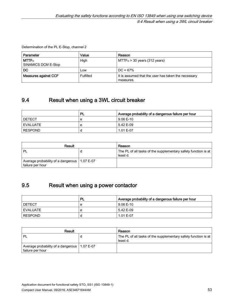
Determination of the PL E-Stop, channel 2
Parameter Value Reason MTTFD SINAMICS DCM E-Stop
High MTTFD > 30 years (312 years)
DC Low DC = 67% Measures against CCF Fulfilled It is assumed that the user has taken the necessary
measures.
9.4 Result when using a 3WL circuit breaker PL Average probability of a dangerous failure per hour DETECT e 9.06 E-10 EVALUATE e 5.42 E-09 RESPOND d 1.01 E-07
Result Reason
PL d The PL of all tasks of the supplementary safety function is at least d.
Average probability of a dangerous failure per hour
1.07 E-07
9.5 Result when using a power contactor PL Average probability of a dangerous failure per hour DETECT e 9.06 E-10 EVALUATE e 5.42 E-09 RESPOND d 1.01 E-07
Result Reason
PL d The PL of all tasks of the supplementary safety function is at least d.
Average probability of a dangerous failure per hour
1.07 E-07
Evaluating the safety functions according to EN ISO 13849 when using one switching device 9.5 Result when using a power contactor
Application document for functional safety STO, SS1 (ISO 13849-1) 54 Compact User Manual, 09/2016, A5E34871844AM
Application document for functional safety STO, SS1 (ISO 13849-1) Compact User Manual, 09/2016, A5E34871844AM 55
Evaluating the safety functions according to EN ISO 13849 when using two switching devices 10
The safety function is split up into three partial systems:
Detect → Evaluate → Respond
As the Respond partial system comprises the E-Stop channel of the SINAMICS DCM and the power switching device, this is again split up.
The assignment to the partial systems is color-coded in the following block diagram:
Orange = "Detect"
Green = "Evaluate"
Blue = "Respond" channel 1
Red = "Respond" channel 2
Gray = Feedback signals
List of abbreviations for the calculations:
SIL Safety Integrity Level SILCL Safety Integrity Level Claim Limit PL Performance Level MTTFD Mean Time to Failure Dangerous B10 Number of cycles, until 10% of the components have failed DC Diagnostic Coverage CCF Common Cause Failure
Evaluating the safety functions according to EN ISO 13849 when using two switching devices 10.1 Evaluation of "Detect"
Application document for functional safety STO, SS1 (ISO 13849-1) 56 Compact User Manual, 09/2016, A5E34871844AM
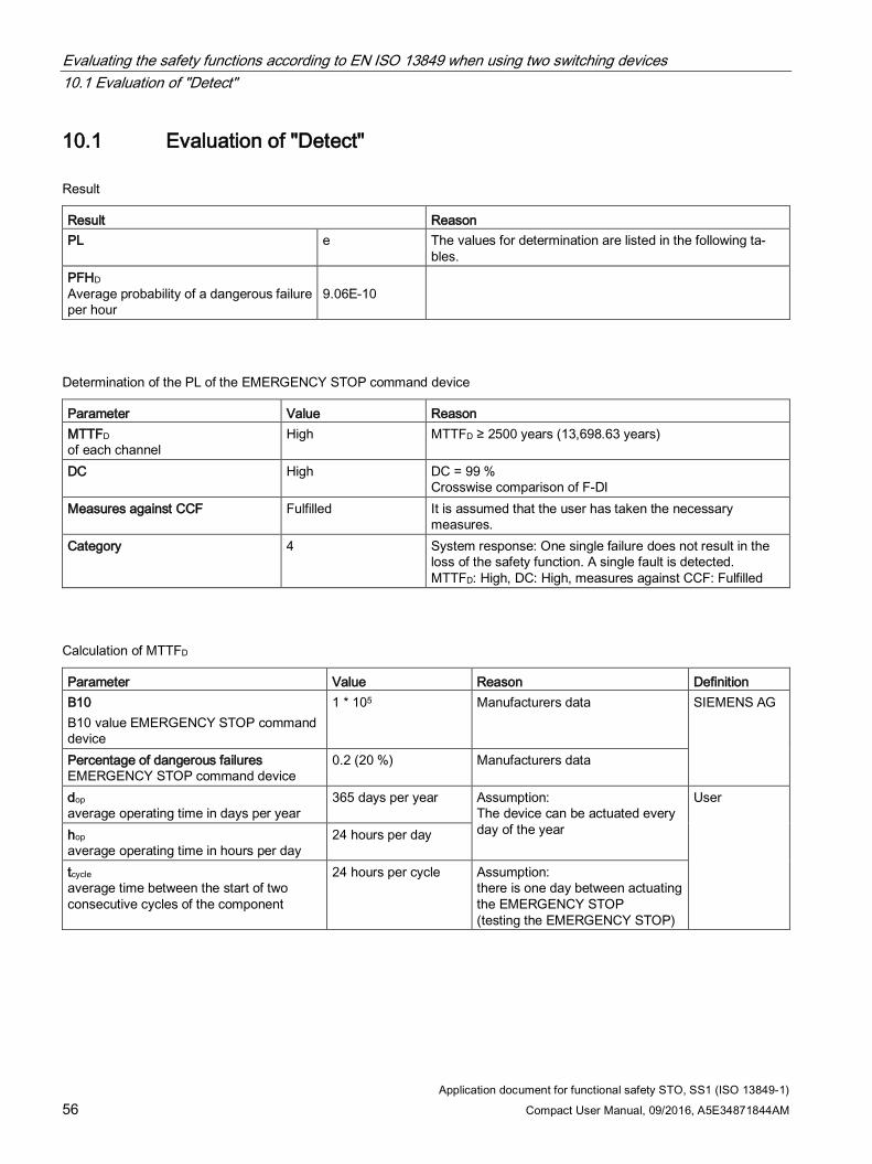
10.1 Evaluation of "Detect"
Result
Result Reason PL e The values for determination are listed in the following ta-
bles. PFHD Average probability of a dangerous failure per hour
9.06E-10
Determination of the PL of the EMERGENCY STOP command device
Parameter Value Reason MTTFD of each channel
High MTTFD ≥ 2500 years (13,698.63 years)
DC High DC = 99 % Crosswise comparison of F-DI
Measures against CCF Fulfilled It is assumed that the user has taken the necessary measures.
Category 4 System response: One single failure does not result in the loss of the safety function. A single fault is detected. MTTFD: High, DC: High, measures against CCF: Fulfilled
Calculation of MTTFD
Parameter Value Reason Definition B10 B10 value EMERGENCY STOP command device
1 * 105 Manufacturers data SIEMENS AG
Percentage of dangerous failures EMERGENCY STOP command device
0.2 (20 %) Manufacturers data
dop average operating time in days per year
365 days per year Assumption: The device can be actuated every day of the year
User
hop average operating time in hours per day
24 hours per day
tcycle average time between the start of two consecutive cycles of the component
24 hours per cycle Assumption: there is one day between actuating the EMERGENCY STOP (testing the EMERGENCY STOP)
Evaluating the safety functions according to EN ISO 13849 when using two switching devices 10.2 Evaluation of "Evaluate"
Application document for functional safety STO, SS1 (ISO 13849-1) Compact User Manual, 09/2016, A5E34871844AM 57
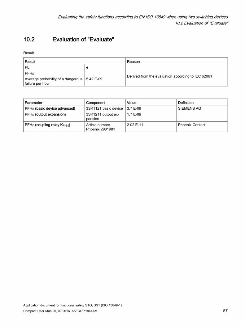
10.2 Evaluation of "Evaluate"
Result
Result Reason PL e
Derived from the evaluation according to IEC 62061
PFHD Average probability of a dangerous failure per hour
5.42 E-09
Parameter Component Value Definition PFHD (basic device advanced) 3SK1121 basic device 3.7 E-09 SIEMENS AG PFHD (output expansion) 3SK1211 output ex-
pansion 1.7 E-09
PFHD (coupling relay KAH[n]) Article number Phoenix 2981981
2.02 E-11 Phoenix Contact
Evaluating the safety functions according to EN ISO 13849 when using two switching devices 10.3 Evaluation of "Respond"
Application document for functional safety STO, SS1 (ISO 13849-1) 58 Compact User Manual, 09/2016, A5E34871844AM
10.3 Evaluation of "Respond"
10.3.1 Evaluation of "Respond" with two power switching devices
10.3.1.1 Evaluation of two 3WL circuit breakers connected in series
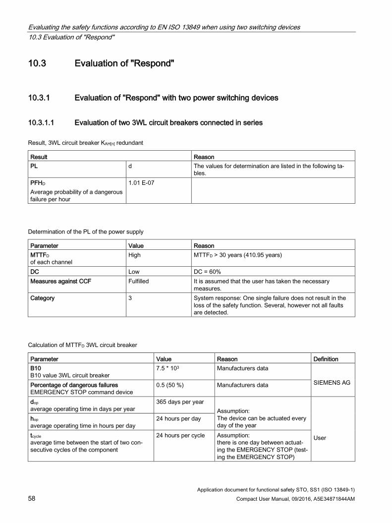
Result, 3WL circuit breaker KAH[n] redundant
Result Reason PL d The values for determination are listed in the following ta-
bles. PFHD Average probability of a dangerous failure per hour
1.01 E-07
Determination of the PL of the power supply
Parameter Value Reason MTTFD of each channel
High MTTFD > 30 years (410.95 years)
DC Low DC = 60% Measures against CCF Fulfilled It is assumed that the user has taken the necessary
measures. Category 3 System response: One single failure does not result in the
loss of the safety function. Several, however not all faults are detected.
Calculation of MTTFD 3WL circuit breaker
Parameter Value Reason Definition B10 B10 value 3WL circuit breaker
7.5 * 103 Manufacturers data SIEMENS AG Percentage of dangerous failures
EMERGENCY STOP command device 0.5 (50 %) Manufacturers data
dop average operating time in days per year
365 days per year Assumption: The device can be actuated every day of the year
User
hop average operating time in hours per day
24 hours per day
tcycle average time between the start of two con-secutive cycles of the component
24 hours per cycle Assumption: there is one day between actuat-ing the EMERGENCY STOP (test-ing the EMERGENCY STOP)
Evaluating the safety functions according to EN ISO 13849 when using two switching devices 10.3 Evaluation of "Respond"
Application document for functional safety STO, SS1 (ISO 13849-1) Compact User Manual, 09/2016, A5E34871844AM 59
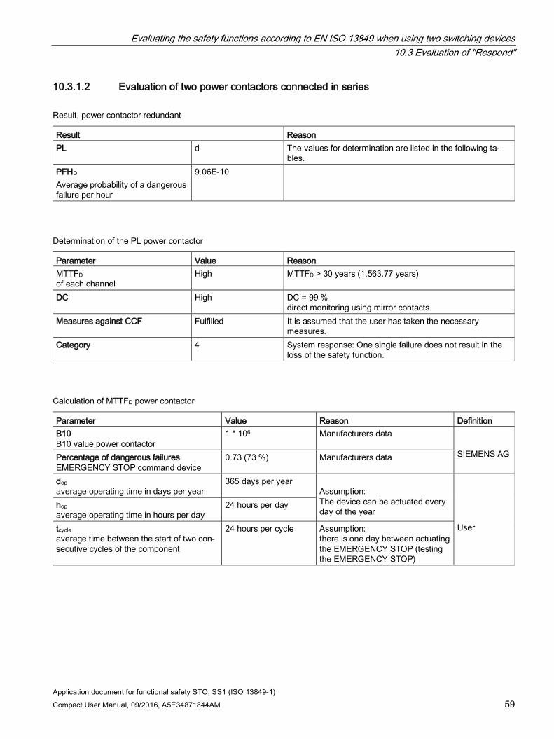
10.3.1.2 Evaluation of two power contactors connected in series
Result, power contactor redundant
Result Reason PL d The values for determination are listed in the following ta-
bles. PFHD Average probability of a dangerous failure per hour
9.06E-10
Determination of the PL power contactor
Parameter Value Reason MTTFD of each channel
High MTTFD > 30 years (1,563.77 years)
DC High DC = 99 % direct monitoring using mirror contacts
Measures against CCF Fulfilled It is assumed that the user has taken the necessary measures.
Category 4 System response: One single failure does not result in the loss of the safety function.
Calculation of MTTFD power contactor
Parameter Value Reason Definition B10 B10 value power contactor
1 * 106 Manufacturers data SIEMENS AG Percentage of dangerous failures
EMERGENCY STOP command device 0.73 (73 %) Manufacturers data
dop average operating time in days per year
365 days per year Assumption: The device can be actuated every day of the year
User
hop average operating time in hours per day
24 hours per day
tcycle average time between the start of two con-secutive cycles of the component
24 hours per cycle Assumption: there is one day between actuating the EMERGENCY STOP (testing the EMERGENCY STOP)
Evaluating the safety functions according to EN ISO 13849 when using two switching devices 10.4 Result when using two 3WL circuit breakers
Application document for functional safety STO, SS1 (ISO 13849-1) 60 Compact User Manual, 09/2016, A5E34871844AM
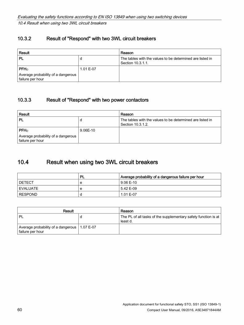
10.3.2 Result of "Respond" with two 3WL circuit breakers Result Reason PL d The tables with the values to be determined are listed in
Section 10.3.1.1. PFHD Average probability of a dangerous failure per hour
1.01 E-07
10.3.3 Result of "Respond" with two power contactors Result Reason PL d The tables with the values to be determined are listed in
Section 10.3.1.2. PFHD Average probability of a dangerous failure per hour
9.06E-10
10.4 Result when using two 3WL circuit breakers PL Average probability of a dangerous failure per hour DETECT e 9.06 E-10 EVALUATE e 5.42 E-09 RESPOND d 1.01 E-07
Result Reason
PL d The PL of all tasks of the supplementary safety function is at least d.
Average probability of a dangerous failure per hour
1.07 E-07
Evaluating the safety functions according to EN ISO 13849 when using two switching devices 10.5 Result when using two power contactors
Application document for functional safety STO, SS1 (ISO 13849-1) Compact User Manual, 09/2016, A5E34871844AM 61
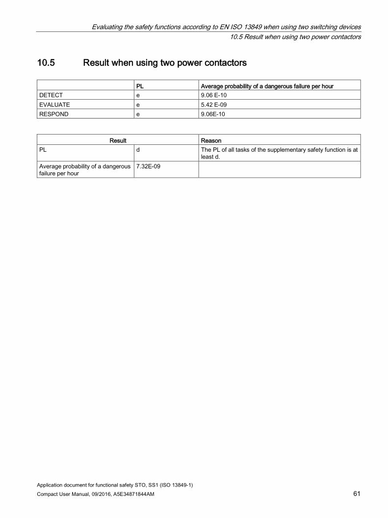
10.5 Result when using two power contactors PL Average probability of a dangerous failure per hour DETECT e 9.06 E-10 EVALUATE e 5.42 E-09 RESPOND e 9.06E-10
Result Reason
PL d The PL of all tasks of the supplementary safety function is at least d.
Average probability of a dangerous failure per hour
7.32E-09
Evaluating the safety functions according to EN ISO 13849 when using two switching devices 10.5 Result when using two power contactors
Application document for functional safety STO, SS1 (ISO 13849-1) 62 Compact User Manual, 09/2016, A5E34871844AM
Application document for functional safety STO, SS1 (ISO 13849-1) Compact User Manual, 09/2016, A5E34871844AM 63
Evaluation of the safety function according to EN 62061 11
The safety function is split up into three partial systems:
Detect → Evaluate → Respond
As the Respond partial system comprises the E-Stop channel of the SINAMICS DCM and the power switching device, this is again split up.
The assignment to the partial systems is color-coded in the following block diagram:
Orange = "Detect"
Green = "Evaluate"
Blue = "Respond" channel 1
Red = "Respond" channel 2
Gray = Feedback signals
List of abbreviations for the calculations:
SIL Safety Integrity Level SILCL Safety Integrity Level Claim Limit PL Performance Level MTTFD Mean Time to Failure Dangerous B10 Number of cycles, until 10% of the components have failed DC Diagnostic Coverage CCF Common Cause Failure
Evaluation of the safety function according to EN 62061 11.1 Evaluation of "Detect"
Application document for functional safety STO, SS1 (ISO 13849-1) 64 Compact User Manual, 09/2016, A5E34871844AM
11.1 Evaluation of "Detect"
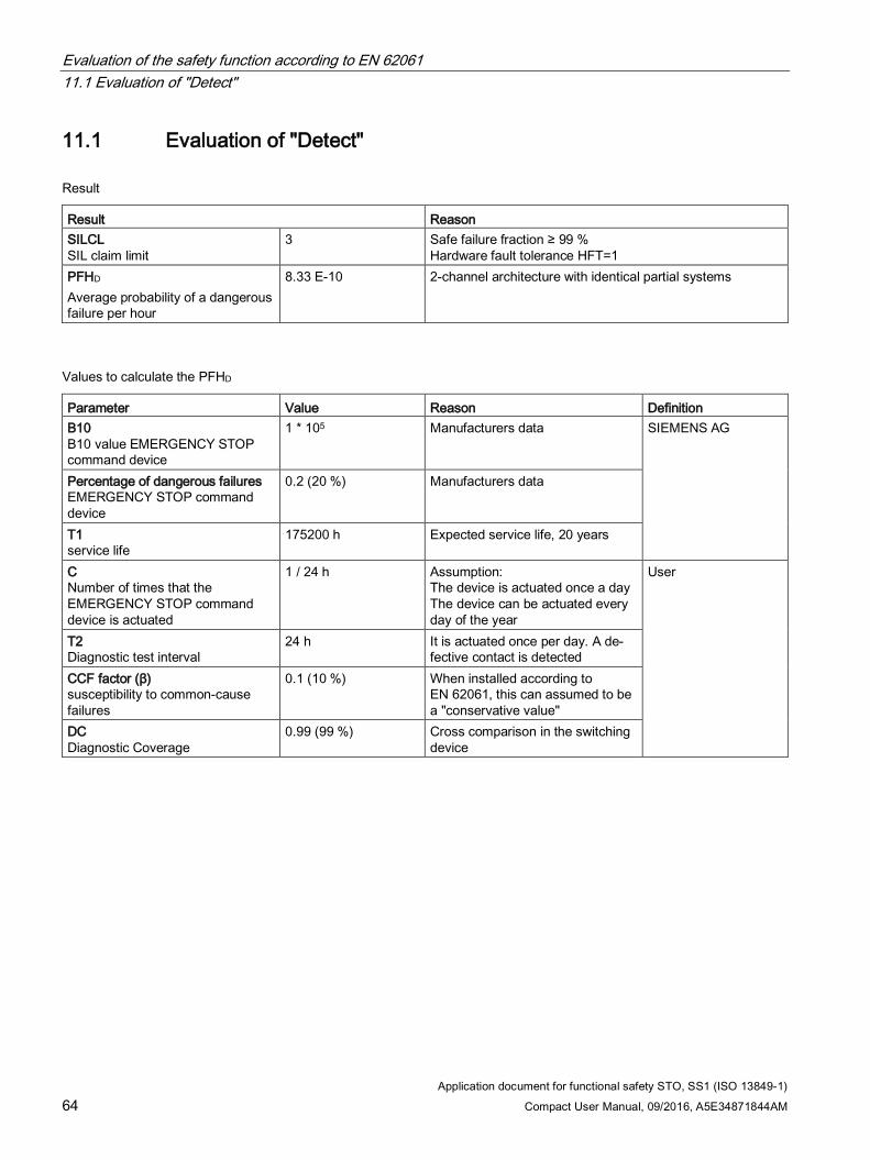
Result
Result Reason SILCL SIL claim limit
3 Safe failure fraction ≥ 99 % Hardware fault tolerance HFT=1
PFHD Average probability of a dangerous failure per hour
8.33 E-10 2-channel architecture with identical partial systems
Values to calculate the PFHD
Parameter Value Reason Definition B10 B10 value EMERGENCY STOP command device
1 * 105 Manufacturers data SIEMENS AG
Percentage of dangerous failures EMERGENCY STOP command device
0.2 (20 %) Manufacturers data
T1 service life
175200 h Expected service life, 20 years
C Number of times that the EMERGENCY STOP command device is actuated
1 / 24 h Assumption: The device is actuated once a day The device can be actuated every day of the year
User
T2 Diagnostic test interval
24 h It is actuated once per day. A de-fective contact is detected
CCF factor (β) susceptibility to common-cause failures
0.1 (10 %) When installed according to EN 62061, this can assumed to be a "conservative value"
DC Diagnostic Coverage
0.99 (99 %) Cross comparison in the switching device
Evaluation of the safety function according to EN 62061 11.2 Evaluation of "Evaluate"
Application document for functional safety STO, SS1 (ISO 13849-1) Compact User Manual, 09/2016, A5E34871844AM 65
11.2 Evaluation of "Evaluate"
Result
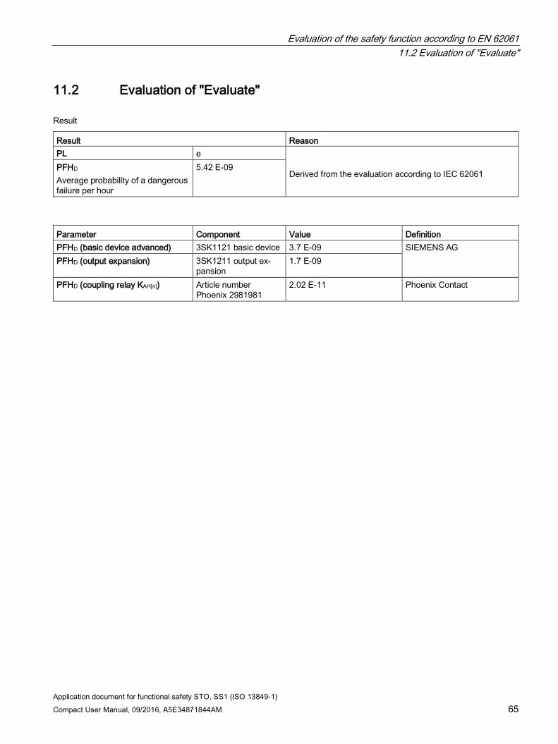
Result Reason PL e
Derived from the evaluation according to IEC 62061
PFHD Average probability of a dangerous failure per hour
5.42 E-09
Parameter Component Value Definition PFHD (basic device advanced) 3SK1121 basic device 3.7 E-09 SIEMENS AG PFHD (output expansion) 3SK1211 output ex-
pansion 1.7 E-09
PFHD (coupling relay KAH[n]) Article number Phoenix 2981981
2.02 E-11 Phoenix Contact
Evaluation of the safety function according to EN 62061 11.3 Evaluation of "Respond"
Application document for functional safety STO, SS1 (ISO 13849-1) 66 Compact User Manual, 09/2016, A5E34871844AM
11.3 Evaluation of "Respond"
11.3.1 Evaluation of "Respond" with two power switching devices
11.3.1.1 Evaluation of two 3WL circuit breakers
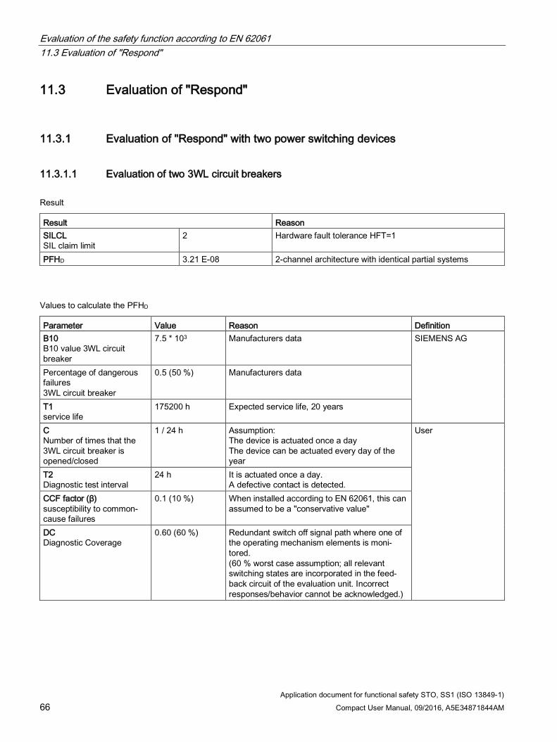
Result
Result Reason SILCL SIL claim limit
2 Hardware fault tolerance HFT=1
PFHD 3.21 E-08 2-channel architecture with identical partial systems
Values to calculate the PFHD
Parameter Value Reason Definition B10 B10 value 3WL circuit breaker
7.5 * 103 Manufacturers data SIEMENS AG
Percentage of dangerous failures 3WL circuit breaker
0.5 (50 %) Manufacturers data
T1 service life
175200 h Expected service life, 20 years
C Number of times that the 3WL circuit breaker is opened/closed
1 / 24 h Assumption: The device is actuated once a day The device can be actuated every day of the year
User
T2 Diagnostic test interval
24 h It is actuated once a day. A defective contact is detected.
CCF factor (β) susceptibility to common-cause failures
0.1 (10 %) When installed according to EN 62061, this can assumed to be a "conservative value"
DC Diagnostic Coverage
0.60 (60 %) Redundant switch off signal path where one of the operating mechanism elements is moni-tored. (60 % worst case assumption; all relevant switching states are incorporated in the feed-back circuit of the evaluation unit. Incorrect responses/behavior cannot be acknowledged.)
Evaluation of the safety function according to EN 62061 11.3 Evaluation of "Respond"
Application document for functional safety STO, SS1 (ISO 13849-1) Compact User Manual, 09/2016, A5E34871844AM 67
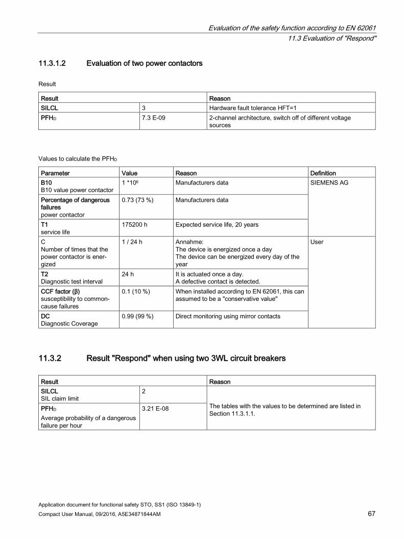
11.3.1.2 Evaluation of two power contactors
Result
Result Reason SILCL 3 Hardware fault tolerance HFT=1 PFHD 7.3 E-09 2-channel architecture, switch off of different voltage
sources
Values to calculate the PFHD
Parameter Value Reason Definition B10 B10 value power contactor
1 *106 Manufacturers data SIEMENS AG
Percentage of dangerous failures power contactor
0.73 (73 %) Manufacturers data
T1 service life
175200 h Expected service life, 20 years
C Number of times that the power contactor is ener-gized
1 / 24 h Annahme: The device is energized once a day The device can be energized every day of the year
User
T2 Diagnostic test interval
24 h It is actuated once a day. A defective contact is detected.
CCF factor (β) susceptibility to common-cause failures
0.1 (10 %) When installed according to EN 62061, this can assumed to be a "conservative value"
DC Diagnostic Coverage
0.99 (99 %) Direct monitoring using mirror contacts
11.3.2 Result "Respond" when using two 3WL circuit breakers Result Reason SILCL SIL claim limit
2 The tables with the values to be determined are listed in Section 11.3.1.1.
PFHD Average probability of a dangerous failure per hour
3.21 E-08
Evaluation of the safety function according to EN 62061 11.4 Result when using two 3WL circuit breakers
Application document for functional safety STO, SS1 (ISO 13849-1) 68 Compact User Manual, 09/2016, A5E34871844AM
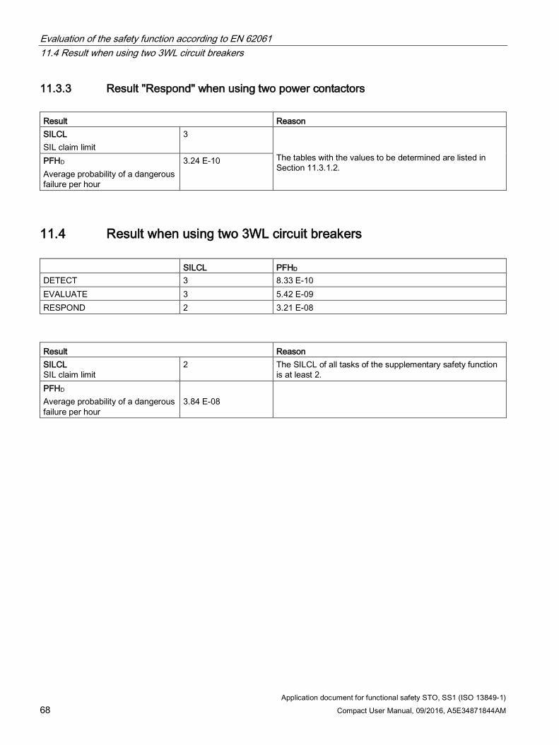
11.3.3 Result "Respond" when using two power contactors Result Reason SILCL SIL claim limit
3 The tables with the values to be determined are listed in Section 11.3.1.2.
PFHD Average probability of a dangerous failure per hour
3.24 E-10
11.4 Result when using two 3WL circuit breakers SILCL PFHD DETECT 3 8.33 E-10 EVALUATE 3 5.42 E-09 RESPOND 2 3.21 E-08
Result Reason SILCL SIL claim limit
2 The SILCL of all tasks of the supplementary safety function is at least 2.
PFHD Average probability of a dangerous failure per hour
3.84 E-08
Evaluation of the safety function according to EN 62061 11.5 Result when using two power contactors
Application document for functional safety STO, SS1 (ISO 13849-1) Compact User Manual, 09/2016, A5E34871844AM 69
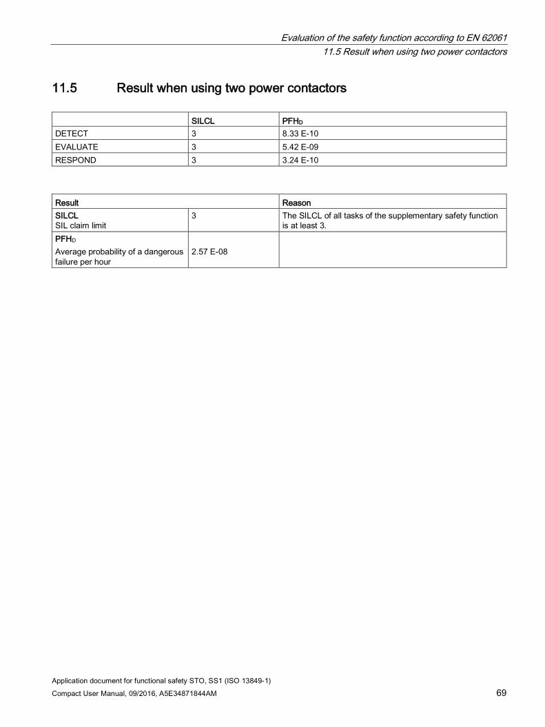
11.5 Result when using two power contactors SILCL PFHD DETECT 3 8.33 E-10 EVALUATE 3 5.42 E-09 RESPOND 3 3.24 E-10
Result Reason SILCL SIL claim limit
3 The SILCL of all tasks of the supplementary safety function is at least 3.
PFHD Average probability of a dangerous failure per hour
2.57 E-08
Evaluation of the safety function according to EN 62061 11.5 Result when using two power contactors
Application document for functional safety STO, SS1 (ISO 13849-1) 70 Compact User Manual, 09/2016, A5E34871844AM
Application document for functional safety STO, SS1 (ISO 13849-1) Compact User Manual, 09/2016, A5E34871844AM 71
Standards 12
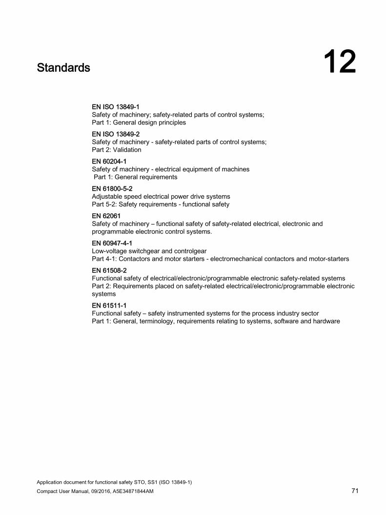
EN ISO 13849-1 Safety of machinery; safety-related parts of control systems; Part 1: General design principles
EN ISO 13849-2 Safety of machinery - safety-related parts of control systems; Part 2: Validation
EN 60204-1 Safety of machinery - electrical equipment of machines Part 1: General requirements
EN 61800-5-2 Adjustable speed electrical power drive systems Part 5-2: Safety requirements - functional safety
EN 62061 Safety of machinery – functional safety of safety-related electrical, electronic and programmable electronic control systems.
EN 60947-4-1 Low-voltage switchgear and controlgear Part 4-1: Contactors and motor starters - electromechanical contactors and motor-starters
EN 61508-2 Functional safety of electrical/electronic/programmable electronic safety-related systems Part 2: Requirements placed on safety-related electrical/electronic/programmable electronic systems
EN 61511-1 Functional safety – safety instrumented systems for the process industry sector Part 1: General, terminology, requirements relating to systems, software and hardware
Standards
Application document for functional safety STO, SS1 (ISO 13849-1) 72 Compact User Manual, 09/2016, A5E34871844AM
Application document for functional safety STO, SS1 (ISO 13849-1) Compact User Manual, 09/2016, A5E34871844AM 73
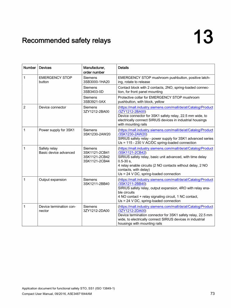
Recommended safety relays 13
Number Devices Manufacturer,
order number Details
1
EMERGENCY STOP button
Siemens 3SB3000-1HA20
EMERGENCY STOP mushroom pushbutton, positive latch-ing, rotate to release
Siemens 3SB3403-0D
Contact block with 2 contacts, 2NO, spring-loaded connec-tion, for front panel mounting
Siemens 3SB3921-0AX
Protective collar for EMERGENCY STOP mushroom pushbutton, with block, yellow
2 Device connector Siemens 3ZY1212-2BA00
(https://mall.industry.siemens.com/mall/de/at/Catalog/Product/3ZY1212-2BA00) Device connector for 3SK1 safety relay, 22.5 mm wide, to electrically connect SIRIUS devices in industrial housings with mounting rails
1 Power supply for 3SK1 Siemens 3SK1230-2AW20
(https://mall.industry.siemens.com/mall/de/at/Catalog/Product/3SK1230-2AW20) SIRIUS safety relay - power supply for 3SK1 advanced series Us = 115 - 230 V AC/DC spring-loaded connection
1 Safety relay Basic device advanced
Siemens 3SK1121-2CB41 3SK1121-2CB42 3SK1121-2CB44
(https://mall.industry.siemens.com/mall/de/at/Catalog/Product/3SK1121-2CB42) SIRIUS safety relay, basic unit advanced, with time delay 0.5-30 s, 4 relay enable circuits (2 NO contacts without delay, 2 NO contacts, with delay) Us = 24 V DC, spring-loaded connection
1 Output expansion Siemens 3SK1211-2BB40
(https://mall.industry.siemens.com/mall/de/at/Catalog/Product/3SK1211-2BB40) SIRIUS safety relay, output expansion, 4RO with relay ena-ble circuits 4 NO contact + relay signaling circuit, 1 NC contact, Us = 24 V DC, spring-loaded connection
1 Device termination con-nector
Siemens 3ZY1212-2DA00
(https://mall.industry.siemens.com/mall/de/at/Catalog/Product/3ZY1212-2DA00) Device termination connector for 3SK1 safety relay, 22.5 mm wide, to electrically connect SIRIUS devices in industrial housings with mounting rails
Recommended safety relays
Application document for functional safety STO, SS1 (ISO 13849-1) 74 Compact User Manual, 09/2016, A5E34871844AM
Number Devices Manufacturer, order number
Details
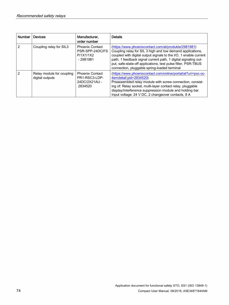
2 Coupling relay for SIL3 Phoenix Contact PSR-SPP-24DC/FSP/1X1/1X2 - 2981981
(https://www.phoenixcontact.com/at/produkte/2981981) Coupling relay for SIL 3 high and low demand applications, coupled with digital output signals to the I/O, 1 enable current path, 1 feedback signal current path, 1 digital signaling out-put, safe-state-off applications, test pulse filter, PSR-TBUS connection, pluggable spring-loaded terminal
2 Relay module for coupling digital outputs
Phoenix Contact PR1-RSC3-LDP-24DC/2X21AU - 2834520
(https://www.phoenixcontact.com/online/portal/at?uri=pxc-oc-itemdetail:pid=2834520) Preassembled relay module with screw connection, consist-ing of: Relay socket, multi-layer contact relay, pluggable display/interference suppression module and holding bar. Input voltage: 24 V DC, 2 changeover contacts, 8 A
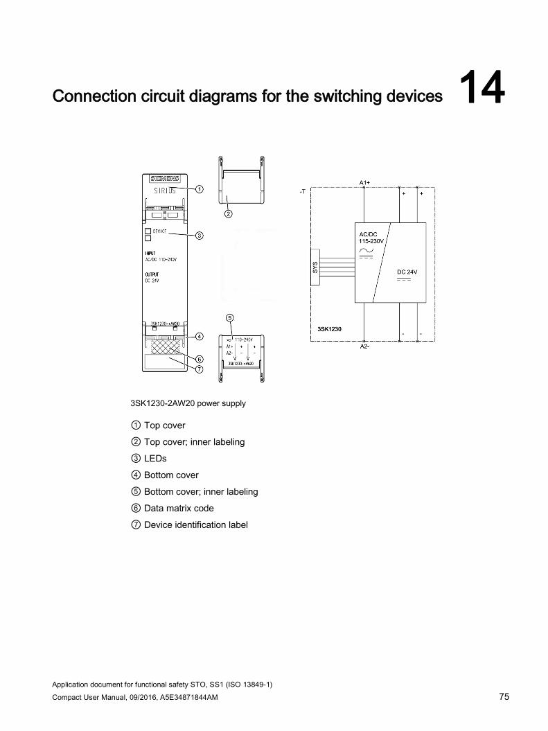
Application document for functional safety STO, SS1 (ISO 13849-1) Compact User Manual, 09/2016, A5E34871844AM 75
Connection circuit diagrams for the switching devices 14
3SK1230-2AW20 power supply
① Top cover
② Top cover; inner labeling
③ LEDs
④ Bottom cover
⑤ Bottom cover; inner labeling
⑥ Data matrix code
⑦ Device identification label
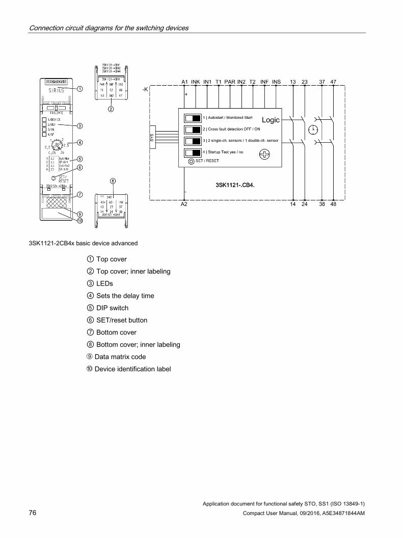
Connection circuit diagrams for the switching devices
Application document for functional safety STO, SS1 (ISO 13849-1) 76 Compact User Manual, 09/2016, A5E34871844AM
3SK1121-2CB4x basic device advanced
① Top cover
② Top cover; inner labeling
③ LEDs
④ Sets the delay time
⑤ DIP switch
⑥ SET/reset button
⑦ Bottom cover
⑧ Bottom cover; inner labeling
➈ Data matrix code
➉ Device identification label
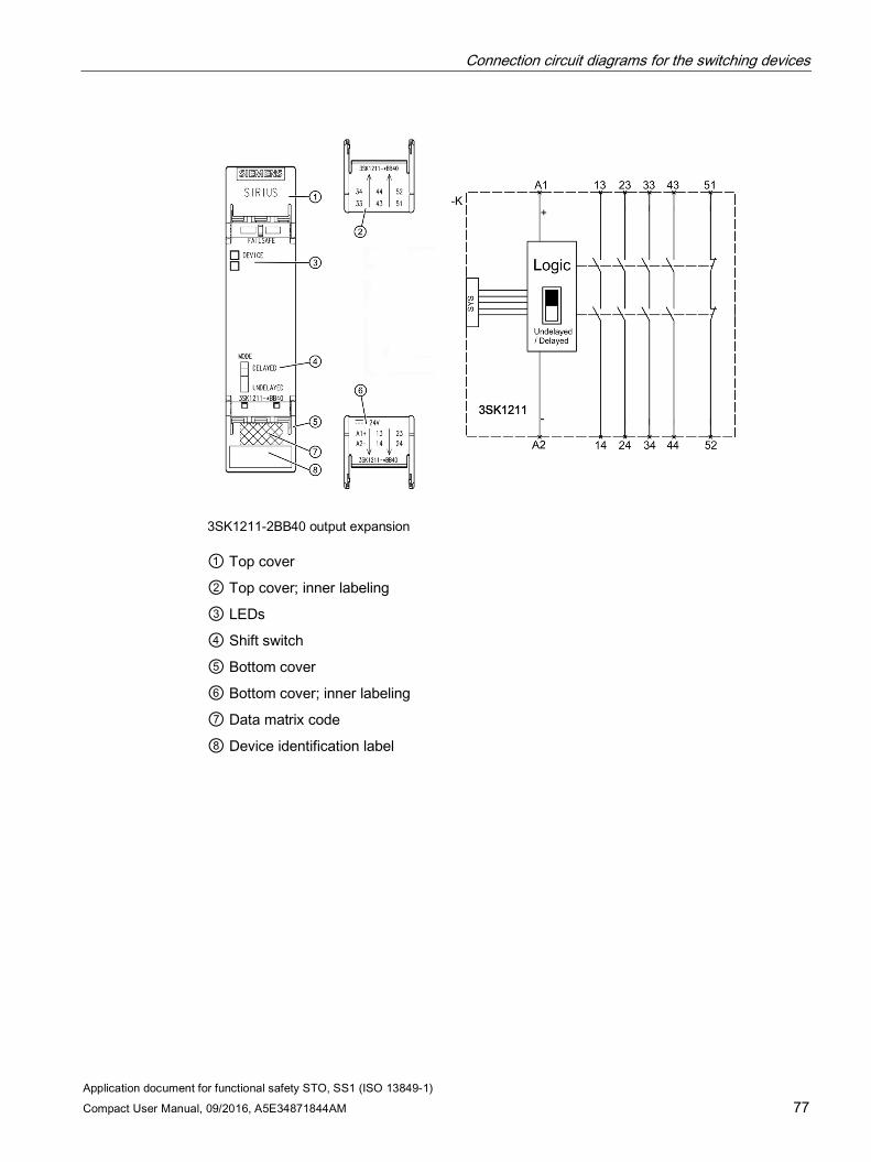
Connection circuit diagrams for the switching devices
Application document for functional safety STO, SS1 (ISO 13849-1) Compact User Manual, 09/2016, A5E34871844AM 77
3SK1211-2BB40 output expansion
① Top cover
② Top cover; inner labeling
③ LEDs
④ Shift switch
⑤ Bottom cover
⑥ Bottom cover; inner labeling
⑦ Data matrix code
⑧ Device identification label
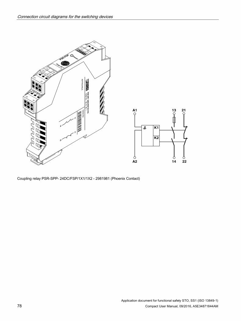
Connection circuit diagrams for the switching devices
Application document for functional safety STO, SS1 (ISO 13849-1) 78 Compact User Manual, 09/2016, A5E34871844AM
Coupling relay PSR-SPP- 24DC/FSP/1X1/1X2 - 2981981 (Phoenix Contact)
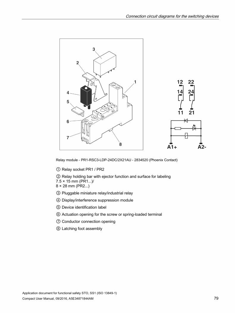
Connection circuit diagrams for the switching devices
Application document for functional safety STO, SS1 (ISO 13849-1) Compact User Manual, 09/2016, A5E34871844AM 79
Relay module - PR1-RSC3-LDP-24DC/2X21AU - 2834520 (Phoenix Contact)
① Relay socket PR1 / PR2
② Relay holding bar with ejector function and surface for labeling 7.5 × 15 mm (PR1...)/ 8 × 28 mm (PR2...)
③ Pluggable miniature relay/industrial relay
④ Display/interference suppression module
⑤ Device identification label
⑥ Actuation opening for the screw or spring-loaded terminal
⑦ Conductor connection opening
⑧ Latching foot assembly
Connection circuit diagrams for the switching devices
Application document for functional safety STO, SS1 (ISO 13849-1) 80 Compact User Manual, 09/2016, A5E34871844AM
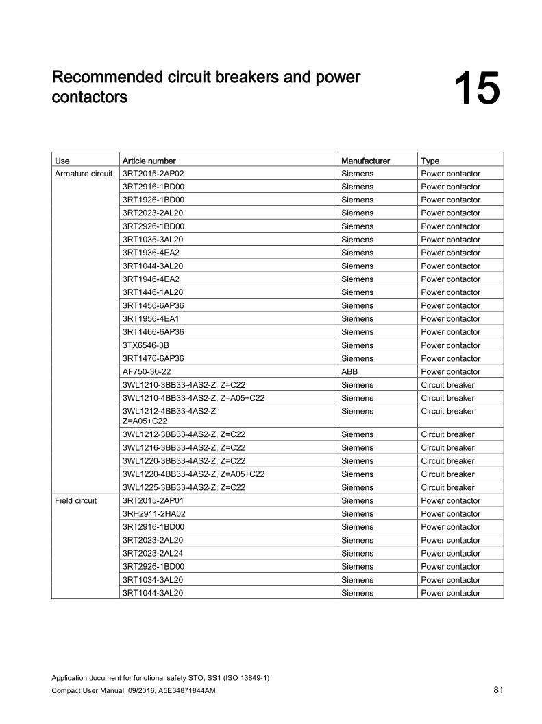
Application document for functional safety STO, SS1 (ISO 13849-1) Compact User Manual, 09/2016, A5E34871844AM 81
Recommended circuit breakers and power contactors 15
Use Article number Manufacturer Type Armature circuit 3RT2015-2AP02 Siemens Power contactor
3RT2916-1BD00 Siemens Power contactor 3RT1926-1BD00 Siemens Power contactor 3RT2023-2AL20 Siemens Power contactor 3RT2926-1BD00 Siemens Power contactor 3RT1035-3AL20 Siemens Power contactor 3RT1936-4EA2 Siemens Power contactor 3RT1044-3AL20 Siemens Power contactor 3RT1946-4EA2 Siemens Power contactor 3RT1446-1AL20 Siemens Power contactor 3RT1456-6AP36 Siemens Power contactor 3RT1956-4EA1 Siemens Power contactor 3RT1466-6AP36 Siemens Power contactor 3TX6546-3B Siemens Power contactor 3RT1476-6AP36 Siemens Power contactor AF750-30-22 ABB Power contactor 3WL1210-3BB33-4AS2-Z, Z=C22 Siemens Circuit breaker 3WL1210-4BB33-4AS2-Z, Z=A05+C22 Siemens Circuit breaker 3WL1212-4BB33-4AS2-Z Z=A05+C22
Siemens Circuit breaker
3WL1212-3BB33-4AS2-Z, Z=C22 Siemens Circuit breaker 3WL1216-3BB33-4AS2-Z, Z=C22 Siemens Circuit breaker 3WL1220-3BB33-4AS2-Z, Z=C22 Siemens Circuit breaker 3WL1220-4BB33-4AS2-Z, Z=A05+C22 Siemens Circuit breaker 3WL1225-3BB33-4AS2-Z; Z=C22 Siemens Circuit breaker
Field circuit 3RT2015-2AP01 Siemens Power contactor 3RH2911-2HA02 Siemens Power contactor 3RT2916-1BD00 Siemens Power contactor 3RT2023-2AL20 Siemens Power contactor 3RT2023-2AL24 Siemens Power contactor 3RT2926-1BD00 Siemens Power contactor 3RT1034-3AL20 Siemens Power contactor 3RT1044-3AL20 Siemens Power contactor

Recommended circuit breakers and power contactors
Application document for functional safety STO, SS1 (ISO 13849-1) 82 Compact User Manual, 09/2016, A5E34871844AM