Embed Size (px)
Citation preview

Application Documents for the Transport Licensing of the Type B(U)F Package
Transport Cask GNS 16
- Safety Analysis Report
Part III Operation / Maintenance
( GNB
GNB
Gesellschaft fOr
Nuklear-Beh~lter mbH
Hollestrale 7A D-45127 Essen Telefon (02 01) 1 09-0 Telefax (02 01) 1 09- 1100/1101

List of Documents
Part III
- OperationlMaintenance
for the Type B(U)F Package
Transport Cask
- GNS 16 -
Report No.:
Date (Revision 8):
Number of Pages:
GNB B 048/97 E
22.02.2001
7
Department/Name Date Signature
Author GNS /TG2/Kluh
Checked by specialist dept. GNB/EBA/Niehaus
Checked by licensing dept. GNS/TG2/ Beine
Released by Sowa
Reproduction in whole or in part of this document and access to third parties is only permitted with the approval of GNB Gesellschaft fcr Nuklear-Behflter mbH, Essen. All rights
with GNB.
Translation approved:
Rev. 8

GNB B 048/97 E Page 2 of 7 Rev. 8
Revision Status
Revision Date Author Reason for Amendment
16.06.1997
15.01.1998
09.02.1998
19.03.1998
09.04.1998
08.05.1998
14.05.1998
21.01.1999
Crefeld
Crefeld
Crefeld
Crefeld
Crefeld
Dr.Heck
Dr.Heck
Crefeld
0
01
First issue
Amendment PV 361/1 and WKP 01, WKP 02
Amendments PV 361
Added PV 430, PV 530, PV 730
Corrections U 111-13 and U 111- 14 Plans for Periodic Inspections
Corrections U I11-1 and U 111-19
U 111-2
MV 32 from Rev. 00 to Rev. 01 U 111-18 Plan for Periodic Inspection WKP-No. 510.060-02 from Rev. 02 to Rev. 03
Plan for Periodic Inspection WKP-No. 510.060-02
from Rev. 03 to Rev. 04
U Il1-1: Rev. 01 to Rev. 2 U 111-3: Rev. 01 to Rev. 03 Change title PV 361/1 E U 111-5: Rev. 00 to Rev. 02 U 111-10: Rev. 06 to Rev. 07 U 111-12: Index:- to Rev. 01 U 111-13: Appendix VI:Rev.1 to Rev. 2 U 111-15: Rev. 01 to Rev. 03 Editorial corrections
02
03
04
05
06
07

GNB B 048/97 E Page 3 of 7 Rev. 8
22.02.2001 Kluh U I1-1: Rev. 02 to Rev. 03 U 111-2: Rev. 01 to Rev. 02 U 111-5: Rev. 02 to Rev. 04 U 111-8: PV 22 replaced by PV 25 U 111-10: Rev. 07 to Rev. 08 U 111-14: PV 119, Rev. b deleted U 111-20: AV 45, Rev. 00 added U 111-21: AV 56, Rev. "1" added U 111-22: AA 28, Rev. 4 added Editorial changes
Amendments are marked by a vertical black line at the left margin.
08

GNB B 048/97 E Page 4 of 7 Rev. 8
U III - 1 GNB B 049/97 E, Rev. 3
O Operation and Maintenance Instructions for the Transport Cask GNS 16
in order to Satisfy the Transport Requirements
U III - 2 MV 32 E, Rev. 02
O Assembly Regulation for the Transport Cask - GNS 16
Test Procedure
U III - 3 PV 36111 E, Rev. 3
O Leak Test -Pressure-Change Measurement - GNS 16
Transport Requirements
together with
O PV 361 E, Rev. 02
Basic test procedure, Leak-Test, Pressure-Change procedure
U Iii -4 PV 43012 E, Rev. 00
O Dose-Rate Measurement, Transport Requirements - GNS 16
together with
* PV 430, Rev. 00
Basic test procedure, Dose-Rate-Measurment
U III -5 PV 53012 E, Rev. 00
O Contamination Measurement - GNS 16
together with
* PV 530, Rev. 04
Basic test procedure, Contamination Measurement
U III - 6 PV 730/2 E, Rev. 00
O Temperature Measurement, Transport Requirements - GNS 16
together with
* PV 730, Rev.00
Basic test procedure, Temperature Measurement, Transport
Requirements
O Document is enclosed U Document is not specific to the model and has already been submitted

GNB B 048/97 E Page 5 of 7 Rev. 8
U III - 7 PV 120, Index: b
* Periodic Inspections on Transport Casks
and Transport and Storage Casks for Radioactive
Materials which require a transportlicense
U III - 8 PV 25, Rev. 00
* Dye Penetration Test Procedure of Transport and Storage Casks
Annex II: Trunnions
U III - 9 PV 24, Rev. 02
0 Test Procedure for Surface Tests
U III - 10 PV 111, Rev. 08
* Overload Test, Transport and Storage Cask, Trunnions and
Trunnion Bolt Joint
U III - 11 PV 112, Rev. 04
* OVERLOAD TEST, Cask Lids, Threaded Boreholes in Order to
Secure the Lid-Suspension Adapter
U III - 12 PV 117, Rev. 01
0 Leak Test, Bubble Test
U III - 13 PV 19, Rev. 01
* Test Procedure for the Visual Inspection
of Transport and Storage Systems,
Appendix I, Rev. 0: "CASTOR Cask Body";
Appendix III, Rev. 0: "Sealing Barriers";
Appendix IV, Rev. 0: "Trunnions";
Appendix VI, Rev. 2: "Screws, screwbolts, nuts and other connecting elements"
U !11 - 14 vacant
O Document is enclosed U Document is not specific to the model and has already been submitted

GNB B 048/97 E Page 6 of 7 Rev. 8
Work Regulations (AV)
U III - 15 AV 25, Rev.03
* WORK REGULATIONS for the Verification of the Shielding Effect of
Transport and Storage Casks for High-Level Radioactive Inventories
U III - 16 AV 28, Rev. "01"
* WORK REGULATIONS for the Verification of the Heat-Dissipation
Capacity of Transport and Storage Casks for High-Level Radioactive
Inventories
U III - 17 WKP No.: 510.060 -01 E, Index: 02
O Plan for Periodic Inspections on a GNS 16 Transport Cask
after 15 Transport Runs or, at the Latest, after 3 Years
U III - 18 WKP No.: 510.060 -02 E, Index: 04
O Plan for Periodic Inspections on a GNS 16 Transport Cask
after 60 Transport Runs or, at the Latest, after 6 Years
U III - 19 WKP No.:510.060 - 04 E, Index: 01
O Plan for Periodic Inspections on Shock Absorbers of a GNS 16
Transport Cask after 15 Transport Runs or, at the Latest, after 3 Years
- at the Earliest, prior to the Next Transport Run
U III - 20 AV 45, Rev. 00
* Visual Inspection and Treatment of Seal Surfaces for Elastomer-/Metal
Sealings
U III - 21 AV 56, Rev. "1"
* WORK REGULATIONS
Treatment of Metal Sealings and Seal Surfaces of Transport and Storage
Casks prior to Loading
O Document is enclosed U Document is not specific to the model and has already been submitted

GNB B 048/97 E
U III - 22
M
Page 7 of 7 Rev. 8
AA 28, Rev. 4
WORK REGULATIONS Decontamination of Transport and Storage Casks
for Spent Fuel Elements
0 Document is enclosed * Document is not specific to the model and has already been submitted


Operation and Maintenance Instructions
for the Transport Cask
- GNS 16
in Order to Satisfy the
Transport Requirements
Report No.:
Date :
Number of Pages:
GNB B 049/97 E
19.02.1999
15
Translation approved: GNB/EBA/Dr. Diersch
This report shall not be reproduced completely or partly or made available to other parties
without prior consent of GNB Gesellschaft f~r Nuklear- Behilter mbH, Essen.
All rights reserved by GNB.
This report is a translation of the German report GNB B 049/97. The information in the
original German version applies in cases of doubt.
Rev. 3
Department/Name
Author: GNSITIG 2/Crefeld
Approved by Special Department: GNB/BEP/Stamprath
Approved by Licensing Department: GNS/TIG 2/Beine
Released by GNB: GNB/PB/Laug
Cýý
GNB B 049/97 E
Document Revisions
Revision No. Date Author Explanation of the Amendment
17.06.1997
23.03.1998
19.02.1999
Crefeld
Crefeld
Crefeld
First issue
Consideration of BAM remarks
Change titel PV 361/1
Page 10: D 3 "Dismantle sealing bolts" removed
Assembling and disassembly of the threaded rods (Item 86) escape general
"Dry-Loading" work steps B 5 - D 13 complete revised
Amendments are indicated by a vertical line at the left margin.
Page 2 of 15 Rev. 3
0
01
2

GNB B 049/97 E Page 3 of 15
Rev. 3
List of Contents Page
1 Purpose and Area of Application 4
2 Terms and Abbreviations 4
3 General Requirements and Remarks 4
4 Fundamental Documents 7
5 Description of the Work Steps for "Wet-Loading" Handling 8
Prior to a Transport Run on Public Roads
6 - Description of the Work Steps for "Dry-Loading" Handling 12
Prior to a Transport Run on Public Roads

GNB B 049/97 E Page 4 of 15 Rev. 3
1 Purpose and Area of Application
These instructions include the work steps which must be taken in a nuclear facility on the
basis of the requirements of the protection objectives with regard to the transport
requirement during the checking of the transport cask - GNS 16 - for a transport run on
public transport routes.
2 Terms and Abbreviations
Approval holder:
BWA:
FR:
MV:
PV:
Tr.:
AA:
Organisation which is registered at the Federal Office for
Radiation Protection (BfS) as the holder of the transport
approval for the transport cask which is subject to approval
(see approval certificate).
Operation and maintenance instructions
Research reactor
Assembly Regulation
Test procedure
Carder
Work instructions
3 General Requirements and Remarks
(1) Prior to transport on public transport routes, the cask must be put into the
condition on which the approval is based.
The holder of the transport approval must take appropriate measures to ensure
that the preparation of the cask for transportation is performed in accordance with
these operation and maintenance instructions (see also § 9 of GGVS).
(2) The item numbers specified in the text for the individual components relate to the
GNB drawing no.:
610.060-01
Transport Cask - GNS 16
and to the GNB parts list no.:
510.060-0111 Transport Cask - GNS 16 -

GNB B 049197 E Page 5 of 15 Rev. 3
(3) All the drawings, PV, MV and AA quoted in the BWA must correspond to the
revision status on which the applicable package-design approval is based. The
revision status of the drawings is shown in the parts list (see type list in the
approval certificate) and the revision status of the PV, MV and AA is shown in the
list of documents in Part III (Operation/Maintenance) according to the applicable
approval certificate.
Documents other than those listed in the list of documents in Part Ill
Operation/Maintenance (quoted in the approval certificate) may also be used
instead in so far as they fulfil the following prerequisites:
- All the documents must guarantee that the criteria of the transport
requirements can be checked. The criteria to be complied with must be
specified.
- Documents specific to the facility may be used in so far as GNS has given its
written agreement to their application.
- The documents drafted by GNS and/or GNB must have been approved by
BAM.
(4) The work steps in these BWA must be incorporated, without any contradictions,
into the specific step-sequence plans of the nuclear facilities where the cask is
checked for transport.
(5) All the tools must be in such a condition that the cask can be checked and
maintained in accordance with the specifications. Those tools and measuring
equipment which are subject to calibration must have a valid calibration certificate.
The identification numbers of the tools and of the calibrated measuring equipment
must be entered in the record.
(6) Prior to use, all the components must be subjected to at least one visual
inspection. Those components which exhibit damage must be replaced with intact
components with identical specifications or, while complying with approved
regulations, must be put into the condition stipulated in the specifications. After the
replacement of components, acceptance tests (e.g. overload test and leak test)
must be repeated if necessary. In principle, any replaced components,
togetherwith their identification numbers, must be recorded in the cask
accompanying book.( log-book)

GNB B 049/97 E Page 6 of 15 Rev. 3
(7) It is recommended to use special equipment, such as an anti-contamination shirt
and sealing bolts for threaded blind holes in the cask body, during the handling
process (wet loading). The use of this auxiliary equipment must be checked in
connection with the specific outline conditions of the nuclear facility.
(8) Depending on the application, the cask may be subject to more stringent
requirements than those defined in order to satisfy transport requirements, e.g.
with regard to shielding and leak tightness. If necessary, such requirements must
be incorporated into the step-sequence plans specific to the facility.
(9) Both "wet loading" and "dry loading" are planned for the GNS 16. The dry loading
is carried out using a mobile loading aid.
The work steps for the two loading variations are basically the same. However, in
order to improve clarity, separate descriptions have been drawn up for the work
steps required in each case.
All the works steps for operation and maintenance prior to a transport run on
public roads in the case of wet loading in a dispatching nuclear facility are
described in Section 5.
In the reverse order, these instructions are also applicable to the unloading of a
cask under water.
In the case of wet unloading, recoo!ing must if app!icable be carried out before
unloading. Should recooling become necessary, corresponding equipment and
the accompanying documents must be made available at an early stage. Before a
possible recooling, the pressure of the inner cask area can be compensated by
means of the quick closure coupling (SVK) and a gas sample taken as the case
may be.
All the works steps for operation and maintenance prior to a transport run on
public roads in the case of dry loading using a mobile loading aid in a dispatching
nuclear facility are described in Section 6.
In the reverse order, these instructions are also applicable to the unloading of a
cask using this mobile loading aid.
* These operation and maintenance instructions must be applied analogously to the
transport of the cask on public transport routes after unloading.

GNB B 049197 E Page 7 of 15 Rev. 3
(10) After 162 transports the trunnions and the trunnion bolts are to be exchanged.
For this, it is assumed that per transport 40 crane handlings take place. For
this purpose, a record is to be maintained concerning each crane handling.
The handlings performed within the scope of periodic inspections are to be
considered as one transport and are to be documented. The documentation of
the crane handlings as well as the trunnion exchange is to be enclosed in the
Cask log book.
4 Fundamental Documents
Assembly drawing, transport cask - GNS 16
- GNB drawing no. 510.060 - 01
- GNB parts list no. 510.060 - 0111
Cask-accompanying book (log book)
Transport papers
Test Procedures
GNB PV 430/2 E
GNB PV 730/2 E
GNB PV 530/2 E
GNS PV 361/1 E
Dose-Rate Measurement,
Transport Requirements - GNS 16
Temperature Measurement,
Transport Requirements - GNS 16
Contamination Measurement - GNS 16
Leak Test, - Pressure change procedure
- GNS 16 - Transport requirements
Assembly Regulation
GNB MV 32 E Assembly Regulation for the Transport
Cask - GNS 16 -
GNB B 049/97 E Page 8 of 15 Rev. 3
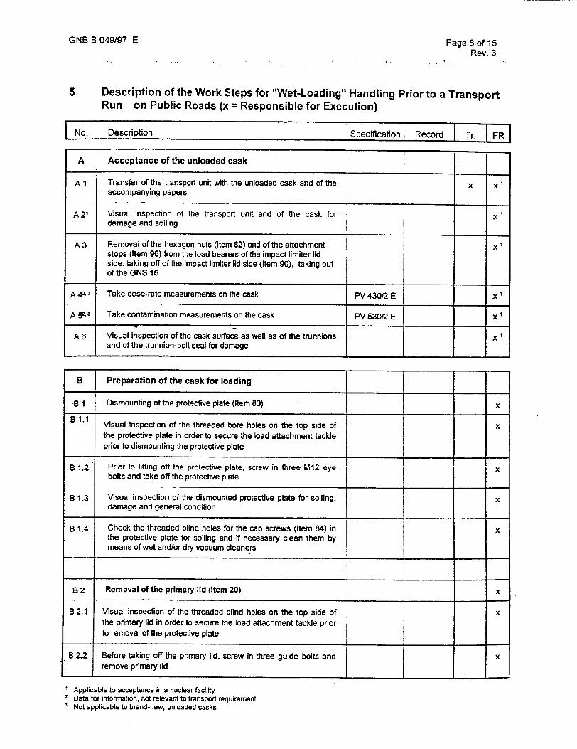
5 Description of the Work Steps for "Wet-Loading" Handling Prior to a Transport
Run on Public Roads (x = Responsible for Execution)
No. Description Specification Record Tr. IFR]
A Acceptance of the unloaded cask
A 1 Transfer of the transport unit with the unloaded cask and of the x 1 accompanying papers
A 21 Visual inspection of the transport unit and of the cask for x damage and soiling
A 3 Removal of the hexagon nuts (Item 82) and of the attachment x stops (Item 96) from the load bearers of the impact limiter lid side, taking off of the impact limiter lid side (Item 90), taking out of the GNS 16
A 42 3 Take dose-rate measurements on the cask PV 430/2 E x
A 52.3 Take contamination measurements on the cask PV 530/2 E x 1
A 6 Visual inspection of the cask surface as well as of the trunnions x and of the trunnion-bolt seal for damage
B Preparation of the cask for loading
-B 1 Dismounting of the protective plate (Item 80) x
B 1.1 Visual inspection of the threaded bore holes on the top side of x
the protective plate in order to secure the load attachment tackle prior to dismounting the protective plate
B 1.2 Prior to lifting off the protective plate, screw in three M12 eye x bolts and take off the protective plate
B 1.3 Visual inspection of the dismounted protective plate for soiling, x damage and general condition
B 1.4 Check the threaded blind holes for the cap screws (Item 84) in x the protective plate for soiling and if necessary clean them by means of wet and/or dry vacuum cleaners
B 2 Removal of the primary lid (Item 20) x
B 2.1 Visual inspection of the threaded blind holes on the top side of x the primary lid in order to secure the load attachment tackle prior to removal of the protective plate
B 2.2 Before taking off the primary lid, screw in three guide bolts and x remove primary lid
Applicable to acceptance in a nuclear facility 2 Data for information, not relevant to transport requirement 3 Not applicable to brand-new, unloaded casks

GNB B 049/97 E Page 9 of 15 Rev. 3
No. I Description Specification Record Tr. FR
B 2.3 Check sealing surface of the primary lid in the cask body for soiling and clean if necessary Check the threaded blind holes for the cap screws/plumbung screws(Items 32/34) in the cask body for soiling and if necessary clean them by means of wet and/or dry vacuum cleaners
B 2.4 Put on sealing surface protection for the primary lid seat and mount cords
B 2.5 Visual inspection for soiling, damage and overall condition - of the removed primary lid (Item 20) - of the removed cap screws/plumbing screws (Item 32/34)
- of the threaded grooves for the O-rings (Item 42) in the primary lid
B 2.6 Visual inspection of the O-rings (Item 42), replace if necessary
B. 2.7 Remove screw plugs (Item 26) at test connections "Al" and "A2", inspect the O-rings (Item 74) visually for damage and replace if necessary
B 3 Removal of the closure lid (Item 28) from the primary lid (Item 20)
B 3.1 Visual inspection for soiling, damage and overall condition - of the removed closure lid (Item 28) - of the removed cap screws (Item 37) - of the threaded blind holes for cap screws in the primary lid
(Item 20)
B 3.2 Visual inspection of the sealing grooves for the O-rings (Items 46/48) in the closure lid and of the relevant sealing surface on the primary lid for soiling and damage
B 3.3 Visual inspection of the O-rings (Items 46/48). Replace seals if necessary
B 4 Removal of the blind plug (Item 24) from the primary lid (Item 20)
B 4.1 Visual inspection of the 0-ring (Item 40) in the removed blind plug. Replace seal if necessary
B 5 Basket (item 15 or 16)
B 5.1 Visual inspection of the basket and of the loading positions for soiling and damage
I
I

GNB B 049/97 E Page 10 of 15 Rev. 3
No. Description Specifcation Record Tr. FR
C Loading
C 1 Load the cask according to the loading plan. Comparison of the Approval Transport x x permissible contents according to the approval with the data of certificate papers the elements provided for transport and confirmation of the contents according to the transport approval. In the loading plan, document the fuel-element numbers and the loading position in the basket
C 2 Remove the sealing surface protection for the primary lid seat x
C 3 Mount the primary lid (Item 20) under water while paying x attention to the position of the orientation point (Item 108). Visual inspection of correct installation
C 4 Partially drain the cavity using the partial-drainage lance x
C 5 Removal of the water from the threaded blind holes of the x primary lid and of the cask body by suction
D Mounting and leak test of the primary lid
D 1 Prepare the cap screws/plumbing screws (Items 32/34) and the x
screw plugs (Item 26) for installation
D 2 Remove 3 guide bolts x
D 3 Screw in the cap screws/plumbing screws (Items 32/34) and MV 32 E x tighten with nominal starting torque (lid on block). The blocking dimension is shown in the manufacturing documentation of the cask
D 4 Drain the sealing space via the testing connections "Al" and x
D 5 Empty the inner cavity of the cask using the drainage lance x
D 6 Installation of the blind plug (Item 24) in the primary lid x
D 7 Carry out the leak test on the 0-rings (Item 42) in the primary lid MV 32 E Transport x
PV 361/1 E papers
D 8 Insert the screw plugs (Item 26) with the O-rings (Item 74) at the MV 32 E testing connections "Al" and "A2"
D Check the sealing surface of the closure lid (Item 28) in the x primary lid for soiling clean if necessary.
_ _eix D 10 Prepare the cap screws (Item 37) for installation.

GNB B 049/97 E Page 11 of 15 Rev. 3
No. Description ISpecification Record Tr. FR'1
D 11 Insert the closure lid (Item 28) into the primary lid while paying MV 32PV X attention to the position according tojthe marks 361/1 E
0 12 Tighten the cap screws (Item 37) of the closure lid (Item 28) to MV 32 E x
the nominal starting torque
D 13 Carry out the leak test on the O-rings (Items 46/48) in the PV361/1 E Transport x closure lid (Item 28) papers
E Putting on of the protective plate (Item 80)
E 1 Inspect the sealing surface of the protective plate for soiling and x clean if necessary
E 2 Visual inspection of the sealing ring (Item 85). Replace seal if X necessary
E 3 After putting on the protective plate, remove three M12 eye bolts x
E 4 Screw in cap screws (Item 84) and tighten with nominal starting MV 32 E x torque
F Preparation of the Cask for Transport
F 1 Take contamination measurements on the cask PV 53012 E Transport- x x papers
F 2 Take dose-rate measurements on the cask PV 43012 E Transoort- X. x papers
F 3 Insertion of the GNS 16 into the impact limiter bottom side (Item MV 32 E x x 95), mounting of the impact limiter lid side (Item 90), tightening of the hexagon nuts (Item 82), mounting of the attachment stops (Item 96) onto the load bearers of the impact limiter on the cover side
F 4 Closing of the 20' transport container; if necessary, checking of x x the functional capacity of the vents
F 5 Take temperature measurements on the outer surfaces of the PV 730/2 E Transport- x x 20' transport container papers
F 6 Take dose-rate measurements on the outer surfaces of the 20' PV 43012 E Transport- x x transport container papers
F 7 Carry out the labelling of the transport unit taking account of the Transport- x x dose rate measured papers
F 8 Draft the transport papers and issue the release for departure Transport- x x papers

GNB B 049197 E Page 12 of 15 Rev. 3
6 Description of the Work Steps for "Dry-Loading" Handling Prior to a Transport Run on Public Roads (x = Responsible for Execution)
No. Description Specification Record Tr. FR
A Acceptance of the unloaded cask
A 1 Transfer of the transport unit with the unloaded cask and of the x x 1 accompanying papers
A 2' Visual inspection of the transport unit and of the cask for x damage and soiling
A 3 Removal of the hexagon nuts (Item 82) and of the attachment x stops (Item 96) from the load bearers of the impact limiter lid side, taking off of the impact limiter lid side (Item 90), taking out of the GNS 16
A 4 2.3 Take dose-rate measurements on the cask PV 430/2 E X
A 52.3 Take contamination measurements on the cask PV 530/2 E x
A 6 Visual inspection of the cask surface as well as of the trunnions x and of the trunnion-bolt seal for damage
B Preparation of the cask for loading
B 1 Dismounting of the protective plate (Item 80) x
B 1.1 Visual inspection of the threaded bore holes on the top side of x
the protective plate in order to secure the load attachment tackle prior to dismounting the protective plate
B 1.2 Prior to lifting off the protective plate, screw in three M12 eye x bolts and take off the protective plate
B 1.3 Visual inspection of the dismounted protective plate for soiling, x damage and general condition
B 1.4 Check the threaded blind holes for the cap screws (Item 84) in x the protective plate for soiling and if necessary clean them by means of wet and/or dry vacuum cleaners
B 2 Removal of the primary lid (Pos. 20) x
B 2.1 Visual inspection of the threaded blind holes on the top side of x the primary lid in order to secure the load attachment tackle prior to removal of the protective plate
B 2.2 Before taking off the primary lid, screw in three guide bolts and x remove primary lid
1 Applicable to acceptance in a nuclear facility. SData for information, not relevant to tansport requirements 3 Not applicable to brand-new, unloaded casks.

GNB B 049197 E Page 13 of 15 Rev. 3
No. Description Specification Record Tr. I FRI
B 2.3 Check sealing surface of the primary lid in the cask body for X soiling and clean if necessary Check the threaded blind holes for the cap screws/plumbing screws (Items 32/34) in the cask body for soiling and if necessary clean them by means of wet and/or dry vacuum cleaners
B 2.4 Put on sealing surface protection for the primary lid seat x
B 2.5 Visual inspection for soiling, damage and overall condition x
- of the removed closure plate (Item 28)
- of the removed cap screws (Item 37)
- of the threaded blind holes for cap screws in the primary lid (Item 20)
B 2.6 Visual inspection of the O-rings, replace if necessary x
B. 2.7 Remove screw plugs (Item 26) at test connections "Al" and x "A2", inspect the O-rings (Item 74) visually for damage and replace if necessary
B3 Removal of the closure lid (Item 28) from the primary lid x (Item 20)
B3.1 Visual inspection for soiling, damage and overall condition x
- of the removed closure lid (Item 28)
- of the removed cap screws (Item 37)
- of the threaded blind holes for cap screws in the primary lid (Item 20)
B 3.2 Visual inspection of the sealing grooves for the O-rings (Items x 46/48) in the closure lid and of the relevant sealing surface on the primary lid for soiling and damage
B 3.3 Visual inspection of the 0-rings (Items 46/48). Replace seals if x necessary
B 4 Removal of the blind plug (Item 24) from the primary lid x (Item 20)
B 4.1 Visual examination of the. O-ring (Item 40) in the removed blind x plug. Replace seal if necessary
B5 Baslet (Item 15 or 16)
B 5.1 Visual inspection of the basket and of the loading positions for x soiling and damage
B6 Sealing surface protection remove -x
B7 Mobile loading aid assemble x

GNB B 049/97 E Page 14 of 15 Rev. 3
No. Description Specification Report Tr. FR
C Loading by means of a mobile loading aid
C 1 Load the cask according to the loading plan. Comparison of the Approval Transport x x permissible contents according to the approval with the data of certificate papers the elements provided for transport and confirmation of the contents according to the transport approval. In the loading plan, document the fuel-element numbers and the loading position in the basket _
C 2 Mobile watertank assemble ' x
C 3 Mobile loading aid disassemble ,-' x
C 4 Mount the primary lid (Item 20) under water while paying x attention to the position of the orientation point (Item 108). Visual inspection of correct installation v"
C 5 Mobile watertank disassemble -, x
C 6 Partially drain the cavity using the partial-drainage lance x
C 7 Removal of the water from the threaded blind holes of the x primary lid and of the cask body by suction
D Mounting and leak test of the primary lid
D 1 Prepare the cap screws/plumbing screws (Items 32/34) and the x screw plugs (Item 26) for installation
D 2 Remove 3 guide bolts x
D 3 Screw in the cap screws/plumbing screws (Items 32/34) and x tighten with nominal tstarting torque (lid on block). The blocking dimension is shown in the manufacturing documentation of the cask
D 4 Drain the sealing space via the testing connections "Al" and x "A2" I I
D 5 Empty the inner cavity of the cask using the drainage lance x
D 6 Installation of the blind plug (Item 24) in the primary lid x
0 7 Carry out the leak test on the O-rings (Item 42) in the primary lid MV 32 E Transport x PV 36111 E papers
D 8 Insert the screw plugs (Item 26) with the O-rings (Item 74) at the MV 32 E x testing connections "Al" and "A2"
D 9 Check the sealing surface of the closure lid (Item 28) in the x
primary lid for soiling clean if necessary.
D 10 Prepare the cap screws (Item 37) for installation. x
D 11 Insert the closure lid (Item 28) into the primary lid while paying MV 32PV x attention to the position according to the marks 361/1 E
D 12 Tighten the cap screws (Item 37) of the closure lid (Item 28) to MV 32 E x the nominal starting torque
D 13 Carry out the leak test on the O-rings (Items 46/48) in the PV 36111 E Transport x closure lid (Item 28) papers

GNB B 049197 E Page 15 of 15 Rev. 3
No. Description Specification Record Tr. FR
E Putting on of the protective plate (Item 80)
E 1 Inspect the sealing surface of the protective plate for soiling and x clean if necessary
E 2 Visual inspection of the sealing ring (Item 85). Replace seal if x
necessary
E 3 After putting on the protective plate, remove three M12 eye bolts x
E 4 Screw in cap screws (Item 84) and tighten with nominal starting MV 32 E x torque
F Preparation of the Cask for Transport
F 1 Take contamination measurements on the cask PV 530/2 E Transport- x x papers
F 2 Take dose-rate measurements on the cask PV 430/2 E Transport- x x papers
F 3 Insertion of the GNS 16 into the impact limiter bottom side (Item MV 32 E x x 95), insertion of the threaded rods (Item 86), mounting of the impact limiter lid side (Item 90), tightening of the hexagon nuts (Item 82). mounting of the attachment stops (Item 96) onto the load bearers of the impact limiter cover side
F 4 Closing of the 20' transport container if necessary, checking of x x the functional capacity of the vents
F 5 Take temperature measurements on the surface of the 20' PV 730/2 E TransDort- x x transport container papers
F 6 Take dose-rate measurements on the surface of the 20' PV 430/2 E Transport- x x transport container papers
F 7 Carry out the labelling of the transport unit taking account of the Transport- x x dose rate measured papers
F 8 Draft the transport papers'and issue the release for departure Transport- X X papers


ASSEMBLY REGULATION
MV 32 E
for the transport cask
GNS 16
This document may not be reproduced or made accessible to third parties, in whole or in part, without the consent of GNB,
Gesellschaft for Nuklear-Beh~lter mbH, Essen. All rights reserved by GNB.
Revision
Date of issue02 22.02.01
Author
Check by techn. dept.
Check by TZQ
Released by GNB
External check
Name Date
Niehaus 22.02.01
WeiR 01.03.01
Kupferschmidt 05.03.01
Diersch 12.03.01
(if required)
Translation approved Weil, GNB-EBA -'f. O. c)(4'
This report is a translation of the German Assembly Regulations MV 32 "02". The information in the original German version applies in cases of doubt.
QR-Q-001 F01 "01" Sh. I of 3 MV 32 E "02" Page 1 of 16
Signature
REVISION STATUS
Explanation of change
22.08.97 M. WeilR
24.04.98 M. WeifR
22.02.01 C. Niehaus
First edition
Annex I Tightening torque Pos. 37 changed
Editorial changes
Supplement concerning the reduction of
the tightening torques at assembled casks Annex 1: modification of the tightening
torques
Alterations to the previous version of this report are marked by a vertical black line at
the left margin of the text.
QR-Q-001 F01 "01" Sh. 1 of 3 MV 32 E "02" Page 2 of 16
Revision Date Author
00
01
02

List of contents
Page
1 Purpose 4
2 Scope of application 4
3 Terms and symbols 5
4 Areas of responsibility 5
5 Cask features 6
5.1 Designations of the cask components 6
5.2 Tightening torques and screw sizes 7
5.3 Check of the leak-tightness function 9
5.4 Load slinging points and overload test 9
5.5 Assembly of the trunnions 10
5.6 Reduction of the tightening torque
at already assembled casks 11
6 Revision service 12
8 Distribution list 12
9 Documents cited 13
Annexes
Annex 1 - Tightening torques for assembly 15
Annex 2 - Masses and tightening torques for the overload test
at load slinging points 16
QR-Q-001 F01 "01"Sh. 1 of 3 MV 32 E "02" Page 3 of 16

Purpose
These assembly regulation describes the cask-specific features of the transport cask GNS 16, which are to be observed for the assembly and dismantling of cask components as part of the commissioning inspection, handling during loading and unloading and the periodic inspections (WKPs). Moreover, these assembly regulations provide an overview of the cask-specific features to be allowed for if this is not specially regulated in other approved documents. The assembly regulation is intended to ensure the proper assembly and dismantling of the components of the cask closure system and the trunnions so that the cask is in an operable condition defined in ac
cordance with its licence.
2 Scope of application
This assembly regulation applies to the transport cask GNS 16.
The item numbers of the individual components mentioned in these regulations relate to the drawing No.:
510.060-01
and to the parts list:
510. 060 -01 / 17/
This assembly regulation does not replace the provisions in the test regulations to be applied, WKP plans and operating and maintenance instructions but is an aid in the implementation of these instructions. In this context this assembly regulation is to be used for commissioning inspections, during loading and unloading and for the periodic inspections (WKPs) of the transport cask GNS 16. Furthermore, the provisions in the master documents (test regulations, operating and maintenance instructions, FPPs and WKP plans) apply.
QR-Q-001 F1 "01" Sh. 1 of 3 MV 32 E "02" Page 4 of 16

These assembly regulation is to be applied when using the following regulations and instructions:
Test regulation PV 120 /4/Periodic inspections on transport casks and transport and storage casks for radioactive materials which are subject
to approval.
GNB B 049/97 /8/ Operating and maintenance instruction for the transport cask GNS 16 to satisfy the requirements under traffic law
3 Terms and symbols
FPP Fabrication and test plan KS Classification level as per TRV006 KTA Nuclear Technology Committee MV Assembly regulation Item Item No. PV Test regulation QR Quality guideline SVK Quick connection plug SW Wrench size WKP Periodic inspections
4 Areas of responsibility
Unless other statements have been made in master documents (inspection regulations, operating and maintenance instruction, FPPs, WKP plans and plant-specific approval documents), these assembly regulation is binding on all people and departments charged with the production, handling and maintenance of the casks of the type GNS 16.
QR-Q-001 F01 "01" Sh. 1 of 3 MV 32 E "02" Page 5 of 16

5 Cask features
5.1 Designations of the cask components
The PV 120 /4/ to be used for the WKPs describes the inspections, irrespective of
the cask type, of the major cask components. The following definitions show the as
signment of the general component designations used in the PV to the applicable
item designations and item numbers according to the parts list 510.060-01/1 for the
transport cask GNS 16.
Component designation in the Item Item designation as per parts list
PV 120
Cask body 2 Cask body
Cask lid 20 Primary lid (for item 2)
Closure of the cask openings 28 Closure lid (for item 20)
Cask lid bolt 32 Cap screw (for item 20)
Cask lid bolt 34 Plumbing screw
(for item 20)
Cask lid bolt 37 Cap screw (for item 28)
Trunnion 12 Trunnion (for item 2)
Trunnion bolt 13 Cap screw (for item 12)
Elastomer seal 42 O-ring (for item 20)
Elastomer seal 46 O-ring (for item 28)
QR-Q-001 F01 "01" Sh. 1 of 3 MV 32 E "02" Page 6 of 16
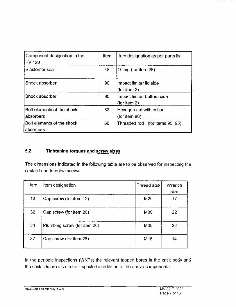
5.2 Tightening torques and screw sizes
The dimensions indicated in the following table are to be observed for inspecting the
cask lid and trunnion screws:
Item Item designation Thread size Wrench size
13 Cap screw (for item 12) M20 17
32 Cap screw (for item 20) M30 22
34 Plumbing screw (for item 20) M30 22
37 Cap screw (for item 28) M16 14
In the periodic inspections (WKPs) the relevant tapped bores in the cask body and the cask lids are also to be inspected in addition to the above components.
QR-Q-001 FO0 '01" Sh. I of 3 MV 32 E "02" Page 7 of 16
Component designation in the Item Item designation as per parts list PV 120
Elastomer seal 48 O-ring (for item 28)
Shock absorber 90 Impact limiter lid side . -_ (for item 2)
Shock absorber 95 Impact limiter bottom side
__(for item 2) Bolt elements of the shock 82 Hexagon nut with collar absorbers (for item 86) Bolt elements of the shock 86 Threaded rod (for items 90, 95) absorbers I I

The necessary screw pre-load force is generally applied by manual assembly using
torque wrenches. The required screw pre-load is generated by a defined and meas
urable torque.
The screw tightening torques to be used for the assembly of the cask components of the GNS 16 are defined in Annex 1. They apply exclusively for the lubricants MOLYKOTE D21 and MOLYKOTE 321 R.
The torque wrenches must permit reliable reading of the necessary tightening
torques or be released at a tightening torque which can be set with adequate accuracy. If no lower values are set for the torque wrench type used (e.g. for manual torque tools according to DIN ISO 6789 /12/) the error limit for setting or reading must not exceed 4% of the torque to be applied. The torque wrenches used must be calibrated with the last calibration to be performed not longer than two years before.
Furthermore, they have to be checked before use with a calibrated torquemeter with the last check to be performed not longer than 6 months before.
For all test and measuring devices the provisions of DIN EN ISO 9001 /11/, item 4.11 concerning the "Monitoring of Test Devices" have to be respected.
Several screws of the same type distributed on a pitch circle are to be tightened in at least four passes and the tightening torque applied in each case is to be graduated (reference values: 50%, 75% and twice 100%) and increased up to the value to be used in accordance with Annex 1. At 100% of the tightening torque as many passes are needed until no screw can be turned any more. In order to prevent canting of the lid or uneven tightening, the screws are to be tightened crosswise.
The screw elements are to be prepared for their use as follows:
(1) Clean screw with cleaning agents and solvents approved for the nuclear sec
tor.
QR-Q-001 F01 "01" Sh. 1 of 3 MV 32 E "02" Page 8 of 16
(2) Coat or spray thread and the underside of the heads with a lubricant approved by GNB.
(3) If washers are used, they are also to be coated on both sides with lubricant
using a brush.
For all screws lubricants confirmed by GNB have to be used which meet the following criteria:
a) free of sulphur and halogen b) compatible with the leak tests (pressure modification method) c) compatible with the material pairings of the cask components d) The coefficients of friction for the existing material pairings must be known
with their range of variation
The lubricants MOLYKOTE D21 and MOLYKOTE 321 R comply with these conditions. The use of other lubricants requires the release in writing by GNB. The lubricants used have to be documented in the cask test book.
5.3 Check of the leak-tightness function
The elastomer seals items 42 and 46 are integral parts of the leak-tight containment. During the commissioning inspection, after a loading and at the periodic inspections (WKP) observance of the specified leak-tightness is to be verified. The vacuumholding test required for this purpose, the test connections and the tightness requirements are described in the test regulation PV 361/1 /5/.
As part of the leak-tightness tests the sealing surfaces on the cask body, the cask lid and the closures of the cask openings are to be inspected visually for damage and contamination.
QR-Q-001 F01 "01" Sh. 1 of 3 MV 32 E "02" Page 9 of 16

Load slinging points and overload test
As part of the mechanical design of the transport cask GNS 16 the load slinging points of the cask body and lid were designed in accordance with the KTA 3905 /1/. The following load slinging points are to be considered:
Load slinging point of Item Item designation as per parts list Requirement as per KTA 3905
Cask body 12 Trunnion (for item 2) increased (4.3)
Cask body 13 Cap screw (for item 12) increased(4.3)
Primary lid 20 1 tapped bore M24 in the centre of increased(4.3) the lid upper side
In the case of load slinging points with increased requirements (4.3) overload tests have to be conducted as part of the periodic inspections (WKPs) in accordance with
KTA 3905.
The cask-specific details of the overload tests of the load slinging points of the GNS 16 are summarized in Annex 2. The performance of the overload tests is regulated in the text regulations PV 111 /2/ and PV 112 /3/.
5.5 Assembly of the trunnions
- Identification control and visual check according to PV 19, annex IV /9/ of the
trunnions for damages - Visual check of the tapped holes of the trunnion seat according to PV 19, an
nex IV /9/ and, if required, cleaning with thread brush and/or blow-off with
compressed air. - Visual check of the trunnion screws according to PV 19, annex VI /9/ and, if
required, cleaning with brush and compressed air. - Cleaning of the underside of the trunnion and of the cask-side contact surface
of the trunnion according to AA-A-014 /10/ (surfaces must be free of grease).
QR-Q-001 F01 "01" Sh. 1 of 3 MV 32 E "02" Page 10 of 16
5.4

- Positioning and assembly of the trunnions (see fig. 1) - If not done already, identification of the trunnion positions, starting from the
zero point of the cask body (see fig. 1) - Lubrication of the screws and tapped holes according to paragr. 5.2
If not done already, identification of the screws of the trunnion no. 1 with serial
numbers (1 - 12). In analogy, the screws of the second trunnion have to be
identified with the serial numbers (13- 24).
Tightening of the trunnion screws according to paragr. 5.2 to the desired
tightening torque according to annex 1.
Trunnion no. Screw identification trunnion
LIPj .I Ol
10a
4
7
Fig. 1: Identification of the trunnions and of the trunnion screws
5.6 Reduction of the tightening torque at already assembled casks
For casks where the trunnion screws originally had been assembled and dismantled
with a tightening torque of 250 Nm, the tightening torques have to be reduced to 150
Nm according to annex 1 at the latest before the next handling.
QR-Q-001 FO1 "01" Sh. 1 of 3 MV 32 E "02" Page 11 of 16

Here the following points have to be observed:
- To avoid a repetition of the overload test no more than 3 screws per trunnion regularly distributed over the perimeter may be untightened at the same time when the tightening torque is reduced.
- The untightening torques have to be checked. In the test book shall be documented that they are between 0.7 and 1.25 times of the original tightening torque.
- If the criterium is not fulfilled the following tests at the screw are required: (i) visual check for damages according to PV 19 annex VI /9/ (ii) OR test (magnaflux test) according to PV 24/6/ (iii) Gauge test for dimensional accuracy of the thread If these tests are negative the screws can be used again.
- If more than 5 screws per trunnion are exchanged a repetition of the overload
test is necessary. - The working has to be executed by consulting the BAM or an expert ap
pointed by them. - A certificate about the successful completion of the working has to be taken
into the the cask test book.
6 Revision service
The revision service for these assembly regulation is to be provided by the development department involved in consultation with the quality department in accordance with the procedures laid down in the QR-Q-001 - GNS documentation system.
The validity date indicated on the cover page "QR-Q001 F 02" when the last index was issued indicates when the changes of this assembly regulation (MV) came into
force.
7 Distribution list
Direct distribution to the departments or subcontractors affected can be carried out on a case-to-case basis in consultation with the quality department.
QR-Q-001 F01 "01" Sh. 1 of 3 MV 32 E "02" Page 12 of 16

9 Documents cited
/1/ KTA 3905 Load slinging points on loads in nuclear power stations
/2/ PV 111 Overload test transport and storage casks, trunnions and trunnion screws
13/ PV 112 Overload test, cask lid, tapped bores for attaching the lid tackle adapter
/4/ PV120 Periodic inspections (WKP) on transport casks and transport
and storage casks for radioactive materials subject to approval
/51 PV 361/1 Test regulations for the performance of leak-tightness tests
Pressure rise measurements - GNS 16 Transport law
/6/ PV 24 rev. 2
/7/ 510.060-01/1
/8/ GNB B 049/97
/9/ PV 19
Test regulation for surface tests
Parts list transport cask GNS 16
Operating and maintenance instruction for the transport cask
GNS 16 in order to satisfy the requirements of traffic law
Test regulation for visual check of transport and storage sys
tems
Annex IV Trunnions
Annex VI Screws, screw bolts, nuts and other connection ele
ments
QR-Q-001 F01 "01" Sh. 1 of 3 MV 32 E "02" Page 13 of 16
Finish-cleaning of components
/11/DIN ISO 9001 Quality management systems
Model for quality assurance (QM presentation in design, development, production, assembly and maintenance) August 1994
/12/DIN ISO 6789 Screw tools, manual torque tools December 1993
The valid revision status of the regulations to be applied (PV and AA) - if not
indicated here - can be found in the reference list of part II, design or part III,
operation/maintenance according to the valid approval certificate. Other regu
lations can be applied if the respective regulations of the operation and main
tenance instructions (see valid approval certificate) are observed. The valid
revision status of the parts lists can be found in the type list (annex to the valid
approval certificate).
QR-Q-001 F01 "01" Sh. 1 of 3 MV 32 E "02" Page 14 of 16
I/10/AA-A-014
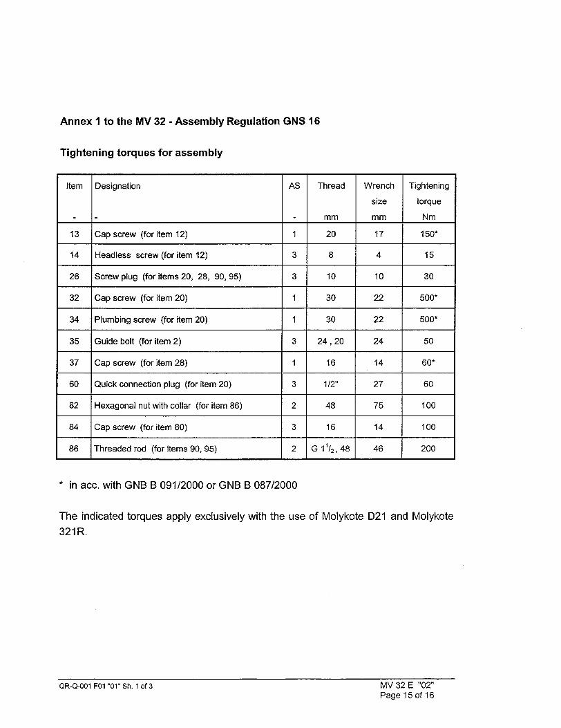
Annex I to the MV 32 - Assembly Regulation GNS 16
Tightening torques for assembly
Item Designation AS Thread Wrench Tightening
size torque
- mm mm Nm
13 Cap screw (for item 12) 1 20 17 150*
14 Headless screw (for item 12) 3 8 4 15
26 Screw plug (for items 20, 28, 90, 95) 3 10 10 30
32 Cap screw (for item 20) 1 30 22 500*
34 Plumbing screw (for item 20) 1 30 22 500*
35 Guide bolt (for item 2) 3 24,20 24 50
37 Cap screw (for item 28) 1 16 14 60*
60 Quick connection plug (for item 20) 3 1/2" 27 60
82 Hexagonal nut with collar (for item 86) 2 48 75 100
84 Cap screw (for item 80) 3 16 14 100
86 Threaded rod (for items 90, 95) 2 G 11/2, 48 46 200
* in acc. with GNB B 091/2000 or GNB B 087/2000
The indicated torques apply exclusively with the use of Molykote D21 and Molykote
321R.
QR-Q-001 F01 "01" Sh. 1 of 3 MV 32 E "02" Page 15 of 16

Annex 2 to the MV 32 - Assembly Regulation GNS 16
Masses and tightening torques for the overload test at load slinging points
(1) Trunnion (item 12), trunnion screws (item 13) and relevant screw-in threads
Max. handling mass GH (on 2 trunnions):
GH = 13 080 kg
Test mass Gp for trunnion screws and screw-in threads at static load:
Gp = 1.5 x GH = 19 620 kg chosen: 20 000 kg
Torques trunnion screws item 13
Tightening torque : 150 Nm
Release torque 1 : = 0.70 x tightening torque = 105 Nm
Release torque 2 • = 1.25 x tightening torque = 187,5 Nm
(2) Primary lid
Mass GD = 1 310 kg
Test mass Gp for static overload test
Gp = 1.5 x GD = 1 965 kg chosen: 2 000 kq
Test mass for dynamic overload test
Gp = 1.25 x GD = 1 638 kg chosen: 1 700 kq
Tightening torque for attachment bolt M24: 150 Nm
QR-Q-001 FOI "01" Sh. 1 of 3 MV 32 E "02" Page 16 of 16


®GNB Gesellschaft for Nuklear-Beh~lter mbH
PV 36111 E
Leak Test Pressure-Change Measurement
- GNS 16
Transport Requirements
This test procedure or part(s) thereof may be reproduced or made available to third parties only with the consent of
the GNB, Gesellschaft fOr Nuklear-Behilter mbH, Essen.
All rights reserved by GNB
Revision
Date of issue
Author
Approved GNS
Approved GNB
Approval by TZQ
Released by GNB
Check mark external
03
04.03.1999
Name
Stamprath
Ilmer
Weilg
Translation approved Dr. Hoist GNS-BEP
This report is a translation of the German Leak Test Specification PV 361/1. The information in the original German version applies in cases of doubt.
Page 1 of 6

®GNB Gesellschaft fur Nuklear-Beh~lter mbH
REVISION STATUS
Date Author Explanation of the Amendment - if necessary, Indication of Pages
26.05.1997
13.01.1998
27.11.1998
Heumos First issue
Crefeld Complete revision
Greven Changes in Sec. 2
Tests carried out as pressure drop measurement as well as pressure increase measurement in case of unloaded casks (see Sec. 3 and Sec. 6).
Description of the condition of the cask ( see Sec. 4 )
Definition of test gas (see Sec. 5).
Definition of allowable standard leak rate as function of cask inventory (see Sec. 7).
Changes in report form sheets
Additions in Sec. 2 and 8.
Text corrections.
04.03.1999 Stamprath Description the steps for drying the space between seals, see Page 4.
Revision
00
01
02
03
PV 361/1 E "' C>3 Page 2 of 6
Approval by TZQ Approval - External for the PV for the PV

Qi GNB Gesellschaft fur Nuklear-Beh;Iter mbH
Validity
Responsibility
Type of Tests
Condition of the Cask
Test gas
Testing Sequence
Permissible Standard Leak Rates
Applicable documents
Testing connections
PV 361/1 FO1 "2":
PV 361/1 F02 "2":
Test report pressure change test
Measuring report pressure change test
List of Contents Page
4
4
4
4
5
5
5
6
Annexes
Annex 1:
PV 36111 E '!W' 03 Page 3 of 6
Approval by TZQ Approval - External
for the PV for the PV

®GNB Gesellschaft fuirNuklear-Behaýlter mbH
1 Validity This test procedure in accordance to the basic test procedure PV 361, is valid for transport
cask GNS 16.
2 Responsibility For execution and documentation of a leak test at the transport cask GNS 16 according to
this test procedure only the authorized test person is responsible.
3 Type of Tests
The tests are based on pressure drop measuring. For unloaded dry casks (for checks during
assembling or cask maintenance) it is possible to use pressure increase measurements
instead of pressure drop measuring.
4 Condition of the Cask
Primary lid is bolted and peaced in lid housing.
Prior to leak testing of the primary lid seals (0-ring, Pos. 42 inner side and outer side) the
cask cavity is partially dewatered and the space between seals (Proofconnections Al and
A2) are completely dewatered.
For leak testing of the primary lid seals of an unloaded cask (0-ring, Pos. 42 inner side and
outer side) by means of pressure increase method, the cask cavity must be dry.
After loading under water the space between- seals (Proofconnections Al und A2) is of a
pressure < 10 hPa to evacuated and sequentialy for at least one hour further to evacuated.
Trough this is the space between seals enough dry for the leak test.
During the leak test of the primary lid seals the cask cavity is in pressure equilibrium with the
outer atmosphere.
The leak test of the primary lid seals is successfully finished before leak test of the closure lid
seals (0-ring, Pos. 46 and 48) starts. The closure lid is mounted and placed in the lid
housing.
PV 36111 E"p• O0
Page 4 of 6
Approval by TZQ Approval - External
for the PV far the PVII
D GNB Gesellschaft fur Nuklear-Beh~lter mbH
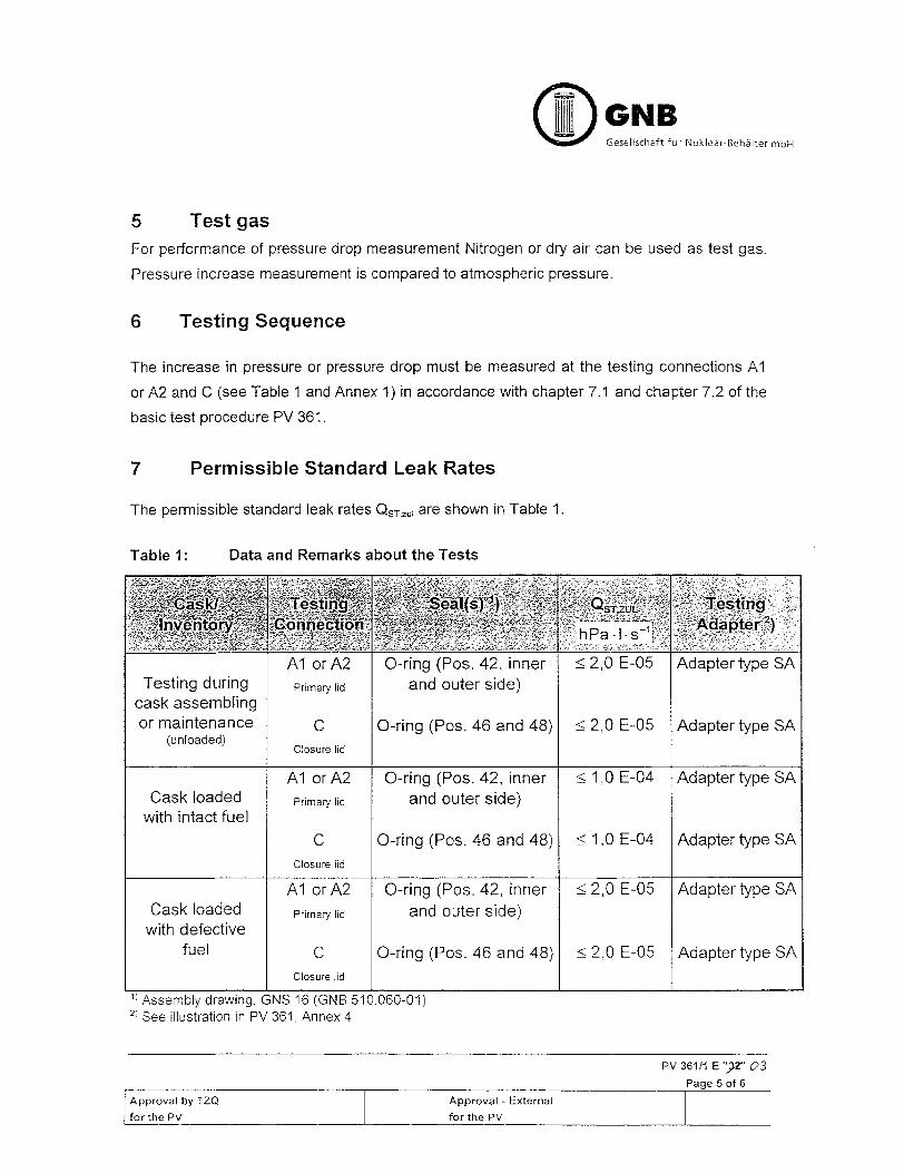
5 Test gas
For performance of pressure drop measurement Nitrogen or dry air can be used as test gas.
Pressure increase measurement is compared to atmospheric pressure.
6 Testing Sequence
The increase in pressure or pressure drop must be measured at the testing connections Al
or A2 and C (see Table 1 and Annex 1) in accordance with chapter 7.1 and chapter 7.2 of the
basic test procedure PV 361.
7 Permissible Standard Leak Rates
The permissible standard leak rates QsT,,o• are shown in Table 1.
Table 1: Data and Remarks about the Tests
) Assembly drawing, GNS 16 (GNB 510.060-01) 2T See illustration in PV 361, Annex 4
PV 36111 E 03
Page 5 of 6
Approval by TZO Approval - External
for the PV for the PV

Geselischaft fjr Nuklear-Behlter mbH
8 Applicable documents
PV 361 Basic test specification for leak tests according to pressure change method
PV 36111 E "'O 0--3
Page 6 of 6
Approval by TZQ Approval - External for the PV Ifor the PVII

® GNB Gesellschaft fOr Nuklear-Behalter mbH
Testing Connections for PV 361/1 E
Proofconnection A2 Pos. 28 Proofoonnection Al
Pos. 42'
Annex 1 to PV 361/1 E "J)' 02 Page 1 of 1
Approval by TZQ Approval - External
for the PV for the PV

Report No.:
® GNB Gesellschaft fOr Nuklear-Beh~lter mbH
Test Report, Pressure-Change Test for PV 361/1
Cask type: GNS 16 Ident-No.:
Test number 1 QST hPa. I s-1
Test number 2 QST hPa I s1
Remarks:
Place of Testingl Facility/ Institution: Measuring Date
Assessment: IJ acceptable U not acceptable
Name Signature Date
Tester
Test supervisor
Independent expert
PV 361/1 E FOI ',W' P. 1 of 1
0-3 Approval by TZQ Approval - External
for the FPV for the PV
Sealing barrier: Primary lid
Permissible Standard Leak Rate:
Cask loaded with intact fuel only QST, ZUL < 1,0 E-04 hPa - I-s-1
Remark: The indicated value applies for the testing of the respective sealing pair. The max. standard leak rate for the whole sealing barrier amounts to 2.0 E-04 hPa. I - s-'.
Cask loaded with defective fuel as well as unloaded casks for checks during assembling or cask maintenance
QST, ZUL < 2,0 E-05 hPa -I -s-1
Remark: The indicated value applies for the testing of the respective sealing pair. The max. standard leak rate for the whole sealing barriers amounts to 4.0 E-05 hPa • I - s-1.
Determined Standard Leak Rates:

Report No.:
®CGNB Gesellschaft for Nuklear-BehýIter mbH
Measuring Report, Pressure-Change Test for PV 36111 E
Type of cask: GNS 16 Ident No.:
Test number 1 2
Sealing face Item: 20 28
Seal Item: 42/42 46/48
Sealing face Item: 2 20
Test borehole Al orA2 C
Data about the Devices and the Test Set-Up
Pressure gauge type/no.
Error limit APuN hPa
Temperature gauge type/no.
Testing volume VPROF I
Data about Execution of the Test
Method (pressure increase I pressure drop)
Test duration ts s
Initial Measurements
Pi hPa
Final Measurements
P2 hPa
S2 °C
Place of Testing/ Facility/ Institution: Date:
Name Signature Date
Tester Test supervisor
Independent expert
PV 36111 E F02 'DO' P. I of 2 03
Approval by TZQ Approval - External
for the PV for the PV

OjjGNB Gesellschaft for Nuklear-Behalter mbH
Measuring Report, Pressure-Change Test for PV 361/1 E
Type of cask: GNS 16 Ident No.:
Test number 1 2 3
Determination of the Measured Results
T, = (,%/°C + 273.2) K K
T2 = (,92/'C + 273.2) K K
T TST hPa
pTST hPa 2, ST 2 T2
1P ST =PST - P2,ST hPa
Pl, ST + P2, ST hPa PM,ST - 2
S _ PST PRUF hPa I -s 1
ts
2
o Q. hPa I s 1 ST 2 2
PM, ST - PST
Place of Testing/ Facility/ Institution: Date:
Name Signature Date
Tester Test supervisor Independent expert
PV 36111 E F02 "JW" P. 2 of 2 03
Approval by- TZQ Approval - External
for the PV for the PV

GNB Geseltschaft for Nuklear-Behdlter mbH
PV 361 E
Basic Test Procedure
Leak Tests
Pressure-Change Procedures
This document may only be duplicated in full or in part or made available to third parties with the consent of GNB
Gesellschaft fOr Nuklear-Beh5iter mbH, Essen.
All rights reserved by GNB.
Revision
Date of issue
Author
Approved by special Dept.
Approved by TZQ
Released by- GNB
Check mark external
Translation approved
02
30.01.1998
Name
Greven, BEP1/WTI
Weig, EBA Ilmer, BEP1
G.Eichel
R.Laug
Masslowski, BAM 111.32
Crefeld, GNS-TIG 2
This report is a translation of the German Basic Test Procedure PV 361,
(Revision 02). The information in the original German version applies in cases of
doubt.
QR-Q-001 FO1 "01 " Sheet 1 of 3 PV 361 E "02"
Page 1 of 14
47. c'6. 74'

GNB -Gesellschaft Fur Nuklear-Behatter mbH
REVISION STATUS
00 20.05.1997
01 07.01.1998
02 30.01.1998
Drafted by
Heumos
Greven
Greven
Explanation of the Amendment - if Necessary, Indication of Pages
First issue
Complete revision
Concideration of the BAM remarks dated 29.01.1998 (Pages 9, 10, 12 and 13 and Annex 3)
QR-Q-001 FOl "01" Sheet 2 of 3 PV 361 S 02"PV 361 E 102"
Page 2 of 14
Revision Date
Approval by TZQ Check Mark - External for the PV for the PV
if required
QR-Q-O01 F01 "01 " Sheet 2 of 3

GNB O Gesellschaft fur Nuktear-Beh<er mbH
Validity
Purpose of the Tests
Qualifications of the Personnel
Type of Tests
Condition of the Components to be tested
Requirements on the Testing Devices
Testing Sequence
Recording
Evaluation
List of the Symbols Used
List of the Abbreviations Used
1 : Saturation Vapour Pressure of Water
2: Conversion Table, Units
Test Report, Pressure-Change Test
Measuring Report, Pressure-Change Test
Test Set-Up
Testing Adapter
QR-Q-001 F01 "01" Sheet 3 of 3 PV 361 E "02"
Page 3 of 14 Approval by TZQ *fCheck Mark- Extemal
for the PV for the PVi "*if required
List of Contents Page
1
2
3
4
5
6
7
8
9
10
11
Table
Table
4
4
4
5
5
6
9
12
12
13
14
Annex 1:
Annex 2:
Annex 3:
Annex 4:
10
14
Page 1 of
Page 1 of Page 2 of
Page 1 of
Page 1 of
1
2 2 1
1

Q GNB Gesellschaft fir Nuklear-Behalter mbH
Validity
This basic test procedure is applicable in conjunction with the respective caskspecific test procedure for those leak tests carried out using a pressure-change procedure. In cases of deviations from the cask-specific test procedure, the specifications in the cask-specific test procedure are decisive.
2 Purpose of the Tests
The measurements serve to check whether the permissible leak rates of the components are complied with.
3 Qualifications of the Personnel
The testers deployed must possess sufficient knowledge in the field of leak tests, in particular of the pressure-change procedures and of vacuum technology, and must be acquainted with the function of the devices and accessories used. The qualifications of the testers must be proven to the responsible authority upon demand.
The leak tests must be carried out by personnel who are qualified according to the guidelines stipulated in EN 473 (e.g. LT1 course of the Deutsche Gesellschaft f(r Zerst6rungsfreie PrLfung e. V. - "German Society for NonDestructive Testing" - in conjunction with in-plant training) or can prove that they have comparable qualifications.
The people deployed as test supervisors must be qualified according to the guidelines stipulated in EN 473 (e.g. LT2 course of the Deutsche Gesellschaft fOr Zerst6rungsfreie PrOfung e. V. in conjunction with in-plant training) or must be able to prove that they have comparable qualifications.
QR-Q-001 FO1 "01" Sheet 3 of 3 PV 361 E "02"
Page 4 of 14
Approval by TZQ Check Mark- External "
for the PV for the PV
"if required

GNB Gesellschaft ffr Nuklear-Behalter mb
4 Type of Tests
The tests are carried out as pressure-drop or pressure-increase measurements.
5 Condition of the Components to be tested
The components to be tested must be dry and free from oils, dust and contaminations in so far as these may have an influence on the quality of the test results.
If any liquid residues remain in the testing volume as a result of the working process, it must be ensured during the testing-volume evacuation necessary for the pressure-increase test that the pressure does not fall below the saturation vapour pressure of water (see Chapter 7.1). As an alternative in such cases, a pressure-drop test may be carried out if necessary or a refrigeration trap (see Annex 3) may be integrated if the cask-specific test procedure provide for this.
QR-O-001 P01 '01" Sheet 3 of 3 PV 361 E 02"PV 361 E "02"
Page 5 of 14
Approval by TZQ * -ICheck Mark - External (for the PV Ffor the PV
if required
QR-Q-O01 F01 "01 " Sheet 3 of 3

GNB Gesellschaft for Nuklear-Beh6lter mbH
6 Requirements on the Testing Devices
The requirements set below must be regarded as minimum demands.
6.1 General Requirements
- Temperature gauge
Measuring range Error limit Resolution of the display If necessary, analog output (see Annex 3)
Recording unit
y/t recorder: Input ports *
Feed Recorder width in y-direction
PC (alternative): Input ports * Recording rate
: 0O- 100 OC : 0.2 K
0.1 K
e.g. O-1OVor4-2OmA
:2 1 mm/min
200 mm
:2 2/s
* Adapted to the analog output of the connected pressure gauge or temperature gauge
Valid calibration certificates must be available for the pressure gauge and temperature gauge. The calibration certificate in each case must not be more than 2 years old.
QR-Q-001 FO1 "01" Sheet 3 of 3 PV 361 E "02"
Iag .. o-I
Approval by TZQ for the PV
Check Mark - External * fn~r t'h• PV
"if required

GNB O Gesellschaft fur Nuklear-Behalter mbH
Pressure-Increase Measurement
Remark: The following testing devices are also required in order to determine the testing volume according to the method described in Chapter 7.3.
Pressure gauge for the pressure in the testing volume
Measuring range Error limit
Resolution of the display Analog output
0 - 200 hPa abs. 0.2 % (in relation to full-scale deflection) 0.1 hPa e.g. O-lOVor4-2OmA
The pressure gauge should be independent of the gas type.
Vacuum pump
Final total pressure with gas ballast : < 1 hPa abs.
Remark: When the pressure gauge is selected and the error limit is thus stipulated, it must be ensured that this results in a test duration appropriate for the testing task (see Chapter 7.4).
QR-Q-001 FO1 "01" Sheet 3 of 3 PV 361 E "02"
Page 7 of 14 Approval by TZQ Check Mark -External for the PV for the PV
"if required
6.2

O GNB Gesellschaft for Nuklear-Behalter mbH
6.3 Pressure-Drop Measurement
- Pressure gauge for the pressure in the testing volume
Measuring range Error limit
Resolution Analog output
1000 - 2000 hPa abs. 0.2 % (in relation to full-scale deflection) 1 hPa e.g. O-10Vor4-2OmA
The pressure gauge should be independent of the gas type.
Test set-up
Pressure-proof up to : 3000 hPa abs. Testing medium : e.g. N2, Ar, He or dry air Gas-cylinder fitting with pressure-reducing valve
Caution: Comply with the Pressure-Vessel Ordinance and accident-prevention regulations!
Remark: When the pressure gauge is selected and the error limit is thus stipulated, it must be ensured that this results in a test duration appropriate for the testing task (see Chapter 7.4).
QR-Q-001 FO1 "01 " Sheet 3 of 3 PV 361 E "02" Page 8 of 14
Approval by TZQ *Check Mark - External *
for the PV for the PV
* if required

0 GNB Geselischaft fur Nuklear-Behalter rnbH
7 Testing Sequence 7.1 Performance of the Pressure Increase Measurement
- Prepare the pressure gauge and the temperature gauge according to the specifications in the instructions for the respective devices
- Assemble the test set-up in accordance with Annex 3, close all the valves
- Determine and record the testing volume VPROF according to Chapter 7.3
- Determine and record the test period ts according to Chapter 7.4
- Open Vp
- If any humidity is present in the testing volume: read off the temperature 8o
- Evacuate the testing volume (final pressure 1 0 ±5 hPa above the saturation vapour pressure of water relevant for the read-off temperature &0 if any humidity is present in the testing chamber, otherwise 10 ±5 hPa abs.) 1)
- Close Vp and begin recording using the recorder
- After a waiting period of at least 10 min: Read off and record the initial pressure Pl. If the signal is not stable or it is foreseeable that the permissible standard leak rate will be exceeded, inform the test supervisor. (There may be a leak in the test set-up, permeation, outgassing, an apparent leak ... )
- Read off and record the initial temperature &1
- After the test period ts: Read off and record the final pressure P2
- Read off and record the final temperature a2
- Label the recordings of the recorder.
- Carry out the calculation according to the measuring report. Complete the measuring report as far as possible
- Dismantle the test set-up
If the determined final pressure is outside the measuring range of the pressure gauge used, the testing volume must be dried.
QR-Q-001 FO1 "01 " Sheet 3 of 3 PV 361 E "02"
Page 9 of 14 Approval by TZQ ceck Mark -*Externa for the PV frthe PV
if required

- GNB GeseIlschaft for Nuklear-Beh86lter mbH
Vapour Pressure of
Performance of the Pressure Drop Measurement
Prepare the pressure gauge and the temperature gauge according to the specifications in the instructions for the respective devices
- Assemble the test set-up in accordance with Annex 3, close all the valves
- Determine and record the testing volume VpR1 F according to Chapter 7.3, in so far as this is not yet known Determine and record the test period ts according to Chapter 7.4
Open Vp
Slowly apply pressure to the testing volume (final pressure 1950 ±25 hPa abs.)
- Close Vp and begin recording using the recorder
- After a waiting period of approximately 10 min: Read off and record the initial pressure pl. If the signal is not stable or it is foreseeable that the permissible standard leak rate will be exceeded, inform the test supervisor. (There may be a leak in the test set-up, permeation, an apparent leak ... ) Read off and record the initial temperature S1
After the test period ts: Read off and record the final pressure P2
- Read off and record the final temperature &2
- Label the recordings of the recorder - Carry out the calculations according to the measuring report.
Complete the measuring report as far as possible - Relieve the pressure from the testing volume - Dismantle the test set-up
QR-Q-001 F01 "01" Sheet 3 of 3 PV 361 E 02" Page 10 of 14
Approval by TZQ Check Mark - ExternalPae1of4
for the PV for the PV
* if required
7.2

- GNB O Gesellschaft fur Nuklear-Behblter mbH
Determination of the Testing Volume
- Open Vo, open Vp
- Carry out evacuation to the final pressure 180 hPa < p < 200 hPa
- Record the pressure P,
- Close Vo
- Carry out evacuation to the final pressure p < 1 hPa
- Close Vp, open V0 , wait for pressure compensation
- Record the pressure P2
- Calculate: VPROF = VREF * (Pl/P2 - 1)
- Record the testing volume VPROF in the measuring report
- Close Vo
Determination of the Test Period ts
-Take the error limit APUN of the pressure gauge from the
manufacturer's documents or from the calibration report and record it
-Calculate the minimum measuring period: AtMIN --=VPROF * APUN / (ST,ZUL
-Calculate the test period: ts = 3 * AtMIN + 30 min
-Record the test period ts in the measuring report
QR-Q-O01 F01 "01" Sheet 3 of 3 PV 361 E "02"
Page 11 of 14 Approval by TZQ Check Mark - External for the PV for the PV
"if required
7.3
Remarks: In so far as this has not yet been carried out, the testing volume must be determined (e.g. according to the following method) by means of calculation or gauging of the capacity by litres.
The prerequisite for the following method is a known reference volume for which VPROF = VREF (see Annex 3) is applicable.
7.4

GNB Gesellschaft fJr Nuklear-BehSlter mbH
8 Recording
The measured values must be recorded and the measured results determined according to the data and formulae in the measuring report of the cask-specifictest procedure (for specimen report, see Annex 2)
It is permissible to use computer printouts for the measuring reports if the content-related specifications and the responsibilities correspond to the stipulations in the copies provided with a test mark.
9 Evaluation
The measured results must be evaluated according to the data in the test report of the cask-specific test procedure (for specimen report, see Annex 1).
QR-Q-001 FO1 "01" Sheet 3 of 3 PV 361 E "02"
Page 12 of 14 Approval by TZQ Ceck Mark -External for the PV frthe PV
*if required

Gesellschaft Fur Nuklear-Beh61ter mbH
List of the : hPa
: hPa
:hPa
: hPa
: hPa
hPa
* hPa.I, s-'
Symbols Used Initial pressure
Final pressure
Initial pressure, converted to the standard temperature
Final pressure, converted to the standard temperature
Average test pressure
Standard pressure 1 01 3 hPa
Leak rate
: hPa-l-s-1 : Standard leak rate
QST,ZUL
T,
T2
TST :
ts s
VPROF I
VREF :1
APST h
APUN h
AtMIN S
&0 .0
&1 :0
&q2 0
QR-Q-001 FO0 "01'
Approval by TZQ for the PV
hPa-I-.s
K
K
Pa
Pa
C
C
C
" Sheet 3 of 3
: Permissible standard leak rate
: Initial temperature
: Final temperature
: Standard temperature 293 K
: Test duration
: Testing volume
: Reference volume
: Standard pressure difference
: Error limit of the pressure gauge
Minimum measuring duration
Temperature in order to determine the necessary final pressure
Initial temperature
Final temperature
PV 361 E "02"
Page 13 of 14
Check Mark - External for the PV
if required
10 Pi
P2
P1,ST
P2,ST
PM,ST
PST
Q
QST

GNB Q Gesellschcft fur Nuklear-Behhlter mbH
List of the Abbreviations Used
Test Procedure ( " Pr~fvorschrift
German Society for Non-Destructive Testing
Deutsche Gesellschaft fir zerstorungsfreie PrOfung, e. V. "
Conversion Table, Units
QR-Q-OO1 FOl 'O1"Sheet3of3 PV 361 E 02'
Approval by TZQ Check Mark - External for the PV for the PV
if required
11
PV
DGZfP
Table 2:
QR-Q-001 F01 "01 " Sheet 3 of 3 PV 361 E "02"

Report No.:
~GNE Gesellschoft fir Nuklear-Behalter mbH
Test Report, Pressure-Change Test for PV 361
Cask Type: Wdent No.: .............
Sealing Barrier: ::,.:, ••
Permissible Standard Leak Rate: z••
QST, ZUL 05" :ý• h~~~
Determined Standard Leak Rate
Test number 1 S9 hPa I s
Test number 2ý--:V hPa • I- s
49* '- • .iY •
Test ri f.j.ST hPa I-s
R' rk,ý
Place of0esting / Facility / Institution: Date.:
Assessment: acceptable 0 not acceptable
Name I Signature Date
Tester
Test supervisor Independent expert *
CR-Q--001 FO 1 '01 - Sheet 3 of 3 Annex 1 to PV 361 E '02"
Page 1 of 1
Approval by TZQ Check Mark - External
for the PV for the PV if required

Report No.:
GNB Gesellschaft for Nuklear-Behalter mbH
Measuring Report, Pressure-Change Test for PV 361
Cask Type: Ident No.:_____________
Test number f2 2 3
Sealing face Item:
Seal Item:
Sealing face Item: __-__-_
Test borehole .
Data about the Devices and the Test Set-Up 0 V
Pressure gauge type/no. . N ; N
Error limit APUN hPa '2" • "• Temperature gauge tyjpeno. " _ __ _ _ t _ Testing volume VpRt)F -,I __,_:_____
Data about ExecutionLA •t .... 6
Method (pressuret grea-e./ pressre T drop) .. ... _-___
Test_ period: "Q .
Initial Measlymen•ts _ _
p hPa
P2~ ..-:0 ____
' "7"•:•o C P!2 W-e. h6a________ _______
Fiar. _ _ _
P2 0_ _ _
Place of Measuring / Facility / Institution: -Date.
I Name Signature Date Tester I Test supervisor Independent expert * I
QR-Q-001 F01 "01 " Sheet 3 of 3 Annex 2 to PV 361 E "02"
Page 1 of 2 Approval by TZQ Check Mark - External
for the PV for the PV
* if required

O GNB Gesellschaft F3r Nuklear-Behdlter mbH
Measuring Report, Pressure-Change Test for PV 361
Cask Type: Ident No.:______________
Test number :.1.' 2 '. 3
Determination of the Measured Results N :
T = (&1/°C + 273.2) K K :"- 1 T 2 = (&2/1 C + 273.2) K K _,.' ___, "
T
1lST 1 SlT hPa..,--•" •
ST p =P a
ST hPa
aP ST = PlST - P2,ST hPa .
P1. ST + P2. S i • - , , AP ST 2 " _._I,,__
A 'PROF ~~t~
ST s ~S
STPST Q ~ M S~S ST_____ Q__APa__
Pac of Measuring / Facility / Institution: Date:______ ____
Name I Signature Date Tester Test supervisor Independent expert I
QR-Q-OO1 FOI '01' Sheet 3 of 3 Annex 2 to PV 361 E -02'
Page 2 of 2
Approval by TZQ Check Mark - External
for the PV for the PV
* if required
Report No.:

Report No.:
(GNB Gesellschaft fur Nuklear-Beha1ter mbH
Test Set-Up for PV 361
- diagrammatic -
"TESTING DEVICE
RECORDING UNIT
T ----
"* if required
* Alternative Components (see Chapter 5)
The reference volume also includes the volume of the connecting lines as far as the valve Vo.
The reference volume must only be assembled whenever it is required in order to determine the testing volume.
The following must be applicable: VPR0F = VREF.
It must be ensured that there is a pressure of 1000 ± 50 hPa in the chamber which is delimited from the testing volume by the seal to be tested. If it is not possible to exclude any pressure increase in this chamber in the course of the test, it is imperative that a pressure-increase test is carried out. In any case, QST can then be determined using PST
In the case of pressure-increase measurements, it is permissible to use a temperature gauge without an analog output and thus to measure the necessary temperatures intermittently.
QR-Q-001 F01 "01 " Sheet 3 of 3 Annex 3 to PV 361 E "02"
Page 1 of 1 Approval by TZQ Check Mark - External
for the PV forthe PV

Report No.:
Testing Adapter for PV 361
- diagrammatic -
QR-Q-001 F01 "01" Sheet 3 of 3 Annex 4 to PV 361 E "02" Pac•_ 1 nf 1
vacuum clamped flange
adapter type AF
.7. auxiliary seal . through borehole
adapter typeS..A- - .
vacuum clamped flange - - through borehole auxiliary seal. thread
-- --- -- - -
adapter typeSA v - -
vacuum. clamped Blange9~ through borehole - quick-closure coupling,.-
Remark:
In the specific-cask test procedure, it is specified which testing adapter is used for which testing volume.
Approval by TZQ Check Mark - External
for the PV for the PV
if required


GNB OD Gesellschafi fur Nukleor Behb6liur mbH
PV 430/2 E
Dose Rate Measurement
Transport Requirements
- GNS 16
This document shall not be reproduced completely or partly or made available to other parties without prior consent of GNB Gesellschaft fur Nuklear-Behalter mbH, Essen.
All rights reserved by GNB.
Revision
Date of issue
Author
Approved by Special Department
Approved by TZQ 2
Released by GNSIGNB
Check mark external
Translation approved
This report is a translation
the original German version
00
10.06.1997
Name
Crefeld, GNS-TIG 2
G6tze, GNS-BEP
E.Seligmann
Laug, GNB/PB
Crefeld, GNS-TIG2
of the German report PV
applies in cases of doubt.
- '21,0'. 19 430/2. The information in
QR-Q-001 FO 01 " Sheet 1 of 3 PV 430/2 E "00"
Page 1 of 4

OGNB Gesellschafi fur Nuklear-Beh6lier rnbH
DOCUMENT REVISIONS
Revision Date
00 10.06.1997
Author
Crefeld
Explanation of the Amendment, if nessessary,
Indication of Pages
First issue
QR-Q-001 F01 "01" Sheet 2 of 3 PV 430/2 E "00"
Page 2 of4 Approved by TZQ C Check mark external
for the PV for the PV
*if required

GNB Gesellschafl fur Nuklear- Behblter (nbH
Page
4
4
4
2 Measurement and evaluation
3 Type of transport
Annex 1 Test Report, Dose Rate Measurement Page 1 of 1
Annex 2 Measuring Report, Dose Rate Measurement, Package
Measuring Points Plan, Package Measuring Report, Dose Rate Measurement,
20' Transport Container
Measuring Points Plan, 20' Transport Container
Measuring Report, Dose Rate Measurement
(additional form sheet)
Page 1 of 5
Page 2 of 5
Page 3 of 5
Page 4 of 5
Page 5 of 5
UI-(-U-OO1 FOl 01' Sheet3of3 PV 43012 E "00"
Approved by TZQ * Check mark external for the PV for the PV
if required
List of contents
1 Validity
QR-Q-001 F01 "01" Sheet 3 of 3 PV 43012 E "00"

O GNB Gesellschaft fhr Nuklear-Beholter mbH
I Validity
This test procedure in accordance to the basic test procedure PV 430, is valid for transport cask GNS 16.
2 Measurement and evaluation
Measurement and evaluation of the results measured is to be made by means of form sheets and in accordance with the measuring point plans (Annex 1 and 2). Should the maximal values occur at points other than those stipulated in the measuring points plan (measurements are to be made at at least these points), the additional measuring points are to be entered in the measuring points plan and indicated in the additional sheet (Annex 2, Page 5 of 5).
3 Type of transport
The
siveGNS 16 transport cask is transported in a 20' transport container under excluuse.
QR-Q-001 F01 01 Sheet 3 of 3 PV 43012 E "00"
Approved by TZQ thPFCheck mark external Page 4 of 4
for the PV Kfor the PV I * if required

Report No.
O GNB Gesellschaft fur Nuklear-Behdlter mbH
Test Report, Dose Rate Measurement for PV 43012 E
Type of cask: GNS 16 ident.No:
Position Maximal dose rate in mSvlh
Gamma Neutron Total (y+n) Limit
External surfaces of the package 10
1 m from the external surfaces of the
package
External surfaces of the vehicle 2
2 m from the external surfaces of the 0.1 vehicle
Points of the vehicle normally occupied by persons, if personal dose rate 0.02 metres are not employed
Place of Testing/ Facility/ Institution: Date:
Assessment IJ acceptable I not acceptable
Name Signature Date Staff of health physics
QR-Q-001 F01 "01" Sheet 3 of 3 Annex 1 of PV 430/2 E "00"
Page I of I ApprovedbyTZQ fotev check mark external for the PV for therPV I
* if required

Report No.
GNB Gesellsdiaft fir Nuklear-Beh6lter mbH
Measuring Report, Dose Rate Measurement, Package for PV 430/2 E
Type of cask: GNS 16 Ident. No.:Measuring devices for Type Manufactur- Device no. Calibration Date of cali
er certificate bration
Gamma dose rate
Neutron dose rate
Numerical quantity for neutron dose rate:
Measuring point Dose Rate in mSv/h No. y value measured n value measured
1 T Lifting lug area
2 S Shock absorber bottom side, centre
3 S Shock absorber cover side, centre
1 B Cask, centre
Background rate D0
Place of testing/ Facilityl Institution: Date:
Assessment Q acceptable L) not acceptable
Name Signature Date Staff of health physics
QR-Q-001 F01 "01" Sheet 3 of 3 Annex 2 of PV 430/2 E "00" Page i of5
Approved byTZQ check mark external Pagehe vft5
for the PV req
"if required

Report No. 0_GNB
GNB Gesellschaft for Nuklear-Beholter mbH
Measuring Points Plan, Package for PV 430/2 E
Type of cask: GNS16 Ident No:
--•--- - -
I~n
Sl Marking Point.
I
K
T = trunnion surface
S = shock absorber surface
B = cask surface
H = cask height
QR-Q-001 F01 "O1 Sheet 3 of 3 Annex 2 of PV 43012 E "00"
Page 2 of 5
Approved by TZQ Check mark external
for the PV ifor therPV I 'if required

Report No. __GNB
Gesellschaft for Nuklear-Beh6lter mbH
Measuring Report, Dose Rate Measurement, 20' Transport Container for PV 43012 E
Type of cask: GNS 16 Ident. No.:Measuring devices for Type Manufacturer Device no. Calibration Date of call
certificate bration
Gamma dose rate
Neutron dose rate
Numerical quantity for neutron dose rate:
Measuring point Dose Rate in mSvlh No. y-value measu- n-value measu
red red 1 External surface container - side wall centre right
2 External surface container - side wall centre left
3 External surface container - side wall upper right
4 External surface container - side wall upper left
5 2 m from the external surface of the container, centre right
6 2 m from the external surface of the container, centre left
7 2 m from the external surface of the container, upper right
8 2 m from the external surface of the container, upper left
Background rate D.
Place of testing/ Facility/ Institution: Date:
Name Signature Date
Staff of health physics
QR-Q-001 F01 "01' Sheet 3 of 3 Annex 2 of PV 43012 E "00"
foI h vcheck mark external. Approved byTZQ r external
*for the PV for the PV
•if required

Report No.
GNB Gesellschoft fur Nukleor-Behdlter mbH
Measuring Points Plan, 20' Transport Container for PV 430/2 E
Type of cask: GNS 16
Measu
Measuring point 1/2
Ident. No.:
ring point Measuring point Measuring point:
3/4 7/8 ./
- .- ......I.........
'-zzK� I
I I?
Measuring point 4
Measuring point
Measuring point 2
Measuring point 6
Measuring point 3 Measuring point 1
Measuring point 7
S'/ -___ _ -Measuring point 5"
L = Length of the 20' Transport Container
H = Height from the lower surface to the roof of the 20' Transport Container
QR-Q-001 F01 "01" Sheet 3 of 3 Annex 2 of PV 43012 E "00"
Page 4 of 5
Approved by TZQ "(' Check mark external
for the PV for the PV
"if required
%

Report No.
GNB Gesellsdiaft fur Nuklear-Behalter mbH
Measuring Report, Dose
Type of cask: GNS 16
Rate Measurement (additional form sheet) for PV 43012 E
Ident. No.:
Measuring devices for Type Manufacturer Device no. Calibration Date of cacertificate libration
Gamma dose rate
Neutron dose rate
Numerical quantity for neutron dose rate:
Measuring point Dose Rate in mSv/h No. , value measured n value measured
Background rate D0
Place of testing! Facility/ Institution: Date:
Name Signature Date Staff of health physics
QR-Q-001 FOI "01" Sheet 3 of 3 Annex 2 of PV 430/2 E "00" n y S
t I
Approved byTZQ Check mark external for the PV for the PV
if required
i i I
i i I


O GNB Ge',celischl fii, Nt)kl(eat-Bdiatlt,.t mbH
PV 530/2 E
Contamination Measurement
- GNS 16
This document shall not be reproduced completely or partly or made available to other parties without prior consent of GNB Gesellschaft fur Nuklear-Behalter mbH, Essen.
All rights reserved by GNB.
Revision
Date of issue
Author
Approved by
Special Department
Approved by TZQ
Released by GNSIGNB
Check mark external
00
10.06.1997
Name
Crefeld, GNS-TIG 2
: G6tze, GNS-BEP
: E.Seligmann
R. Laug
Translation approved Crefeld, GNS-TIG2
This report is a translation of the German report PV
the original German version applies in cases of doubt.
530/2. The information in
QR-O 001 P01 '01" Sheet 1 of 3 PV 530/2 E ,.OO"PV 530/2 E 400"
Page 1 of 4QR-Q-O01 F01 "01 " Sheet 1 of 3
O GNB Q CGesellschafh f6- Nuklear-Behalter rnbH
DOCUMENT REVISIONS
00 11.06.1997
Author
Crefeld
Explanation for the Amendment,
if nessessary
Indication of pages
First issue
QR-Q-001 F01 "01 " Sheet 2 of 3 PV 530/2 E ,,00" Page 2 of4
Approved by TZQt P Check mark external *ae 2 of 4
for the PV ifor the PV
if required
Revision Date

Gesellschaft fur Nuklear-Beh6lter rnbH
1 Validity
2 Measurement and evaluation
3 Transport
Annex 1 Test Report, Contamination Measurement
Annex 2 Measuring Report, Contamination Measurement
Measuring Report, Contamination Measurement
(additional form sheet)
Plan of Measuring Points,
Contamination Measurement
Page 1 of 1
Page 1 of 3
Page 2 of 3
Page 3 of 3
QR-Q-001 FO0 "01" Sheet 3 of 3 PV 530[2 E .00"
Page 3 of 4 Approved by TZQo Check mark external* for the PV for the PV
if required
List of contents Page
4
4
4

O GNB O CGeselIsdcaft fir Nuklear-Behdlter mbH
1 Validity
This test procedure in accordance to the basic test procedure PV 530, is valid for the transport cask GNS 16.
2 Measurement and evaluation
Measurement and evaluation of the results is to be made by means of form sheets and in accordance to the plan of measuruing points (Annex 1 and 2).
Any additional points are to be noted in the plan of measuring points and indicated in the additional form sheet (Annex 2, Page 2 of 3).
3 Transport
The GNS 16 transport cask is transported in a 20' transport container under exclu
sive use.
QR-Q-O01 F01 "01" Blatt 3 von 3
Approved by TZQ
for the PV for the PV
PV 530/2 E .00"
Seite 4 von 4
. if required]L

O GNB Gesellschafl for Nuklear-Behblter mbH
Test Report, Contamination Measurement for PV 530/2 E
Type of cask: GNS 16 Ident No.
Beta-Contamination < 4 Bq/cm 2 D acceptable D not acceptable
caIp-y ratio:
Alpha Contamination < 0,4 Bq/cm2 D1 acceptable D- not acceptable
Remarks / Notices:
Place of Testing/ Facility/ Institution: Date:
Name Signature Date Staff of health physics
QR-Q-001 FO1 "01" Sheet 3 of 3 Annex 1 of PV 53012 E "00"
Page 1 of 1 Approved byTZQ Check mark external
for the PV for the PVr *if required

O GNB Gesellsd~afi fmu Nuklear-BE
Measuring Report, Contamination Measurement for PV 530/2 E
Type of cask: GNS 16
Measuring device
Device No.:
Measuring time:
Ident No.:
Background ne Calibration source Si
SBackground Total coun- n-ne 0.33/ki 0.67/, A 1) Measuring point ns [s"I ting rate Is-'] fcm"=] [cm"
2] [Bq/cml
n [s-1] _ __._I
a 13 a a 3 a 13 a a 1 Protection plate, centre
2 Trunnion, upper 900
3 Trunnion, upper 2700
4 Cask head 0*
5 Cask head 1800
6 Cask surface, upper 900
7 Cask surface, upper 2700
8 Cask surface, centre 900
9 Cask surface, centre 2700
10 Cask surface, lower 900
11 Cask surface, lower 900
12 Cask surface bottom side 00
13 Cask surface bottom side 900
14 Cask surface bottom side 1800
15 Cask surface bottom side 2700
16 Cask bottom, centre
1 A = (n - n.) 0.133 for ot radiation, A = (n - nB) 0.067 for P radiation
2) When an other qualified procedure is employed, only this column is to be filled ir
and 1) no longer applies Place of Testing/ Facility/ Institution: Datee_ _
Name Signature Date
Staff of health physics
QR-Q-001 F01 "01 " Sheet 3 of 3 Annex 2 of PV 53012 E "00" Page 1 of 3
Approved by TZQ Check mark external for the PV " > for the PV
if required

O GNB Geselischafl fur Nuklear-Behalter inbH
Measuring Report, Contamination Measurement (additional form sheet) for PV 530/2 E
Type of cask: GNS 16 Ident No.:
Masuring device:
Device No.:aBcgon_
Background n_ Calibration source
Measuring time:
1} A = (n - nB) 0133 for ax radiation, A = (n -n.) 0.067 for 3 radiation ' i 6i
2) When an other qualified procedure
and 1) no longer applies
ace of Testina/ Facilitv/ Institution:
is employed, only this column is to be filled in
Date :
Name Signature Date
taff of health physics
1 *l {
QR-Q-001 F01 "01" Sheet 3 of 3 Annex 2 of PV 530/2 E "00"
Page 2 of 3 1Approved by TZQ o vCheck mark external for the PV ifor the PV
*if required

O GNB Gesellschafi f6r Nuklear-Behlter mbH
Plan of Measuring Points,Contamination Measurement for PV 530/2 E
Type of cask: GNS 16
7 J
i 3
[dent No.:
_ I -
_ - 8
10
~12.
Marking Point
-G-
QR-Q-001 F01 "01 Sheet 3 of 3 Annex 2 of PV 530/2 E .00"
Page 3 of 3
Approved by TZQ Check mark external
for the PV for-the PV1
* f required
t
I I


Q GNB Gesuschd)1 6ur INtkJ(! BA. [1hcj,ýi rn bH
PV 730/2 E
Temperature Measurement
Transport Requirements
- GNS 16
This document shall not be reproduced completely or partly or made available to other parties without prior consent of GNB Gesellschaft fur Nuklear-Behtlter mbH, Essen.
All rights reserved by GNB.
Revision
Date of issue
Author
Approved by Special Department
Approved by TZQ
Released by GNSIGNB
Check mark external
Translation approved
00
12.06.1997
Name
Crefeld, GNS-TIG 2
Gdtze, GNS-BEP
: E.Seligmann
Laug, GNB/PB
Crefeld, GNS-TIG2
This report is a translation of the German report PV 730/2. The information in
the original German version applies in cases of doubt.
PV 730/2 E ,00"
Page 1 of 4
QR-Q-001 F01 ý01 " Sheet 1 of 3

Gesellschafil fur Nuklear-Behalter mbH
DOCUMENT REVISIONS
Author
, Crefeld
Explanation of the Amendents,
if nessessary
Indication of Pages
First issue
QR-Q-001 FO1 ,01' Sheet 2 of 3 PV 730/2 E ,,00"
Page 2 of 4
Approved by TZQ zvCheck mark external
for the PV for-theoPVhePV
Revision
00
Date
12.06.97
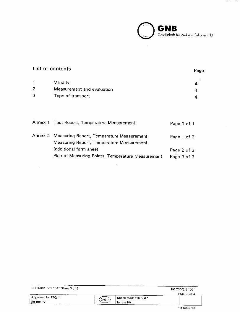
GNB Gesellschaft fu~r Nuklear-Beh~lter rnbH
List of contents
Validity
Measurement and evaluation
Type of transport
Annex 1 Test Report, Temperature Measurement
Annex 2 Measuring Report, Temperature Measurement
Measuring Report, Temperature Measurement
(additional form sheet) Plan of Measuring Points, Temperature Measurement
Page 1 of 1
Page 1 of 3
Page 2
Page 3
of
of
3
3
QR-Q-001 FO0 "01" Sheet 3 of 3 PV 73012 E "00"
Page 3 of 4 Approved by TZQ *fCheck mark external
for the PV irforthe PV
if reouired
1
2
3
Page
4
4
4
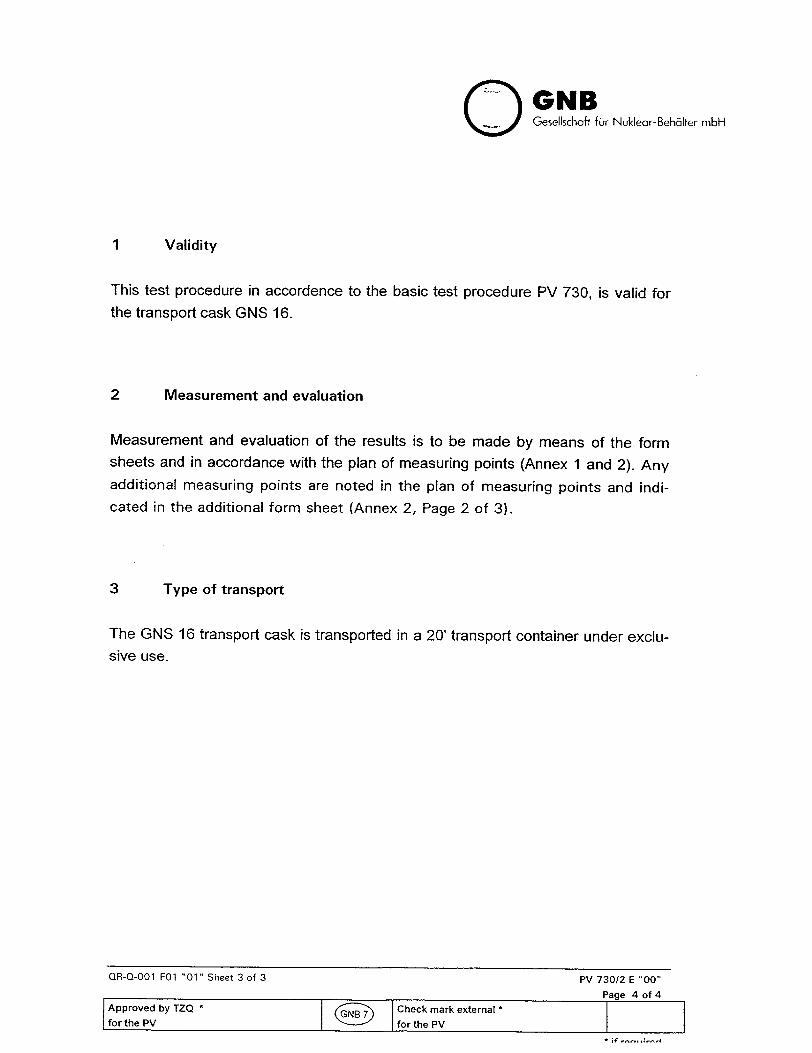
O GNB Gesellschaf fur Nuklear-Beh6lter rnbH
1 Validity
This test procedure in accordence to the basic test procedure PV 730, is valid for
the transport cask GNS 16.
2 Measurement and evaluation
Measurement and evaluation of the results is to be made by means of the form sheets and in accordance with the plan of measuring points (Annex 1 and 2). Any additional measuring points are noted in the plan of measuring points and indicated in the additional form sheet (Annex 2, Page 2 of 3).
3 Type of transport
The GNS 16 transport cask is transported in a 20' transport container under exclu
sive use.
QR-Q-001 F01 "01" Sheet 3 of 3 PV 730/2 E "00"
Page 4 of 4 Approved by TZQ Check mark external *
for the PV ED- I for the PV

Report No.
Gesellschaft for Nuklear-Beh61ter mbH
Test Report,
Type of cask: GNS 16
Temperature Measurement for PV 730/2 E
Ident. No.:
Assessment:
Maximum admissible temperature _> surface temperature a3max
IQ acceptable [Q not acceptable
Place of Testing/ Facility/ Institution: Date:
I L __________________ L ______________________
Annex 1 of PV 73012 E -00"
Page 1 of 1
Apprfor the PV Check mark external
if required
Measuring Surface temperature Maximum admissible point temperature (transport under exclusive use [°C]
S3max[ 0C] (,gmax= au3 + 47K)
Name Signature Date
Executive staff
I I* I.

Report No.
O GNB Geselischaff fir Nuklear-Behalter mbH
Measuring Report, Temperature Measurement for PV 73012 E
Type of cask: GNS 16 Ident No:
Measuring device Type Manufacturer Device No.:
Surface temperatures [0 C] Corrected surface temperatures a., [fCi
Time of the last three measurements t t + 1h t + 2h Measuring points / temperature (3j) 31 &2 &3 4•o = &o2 = .o3 =
_ _ _ _2-(au2 -Sul) q3-(iau3--u1)
1 Right side, centre _
2 Left side, centre
3 Right side, at the top
4 Left side, at the top
(maximum value of the temperatures &_3)
Ambient temperatures (ui) ul &. u2 !,3 Place of measurement for aU:
Stationary state A-q=j&oI-So21 [K] Aa=I!%q1-S 3I [K] A A [K]
admissible
1 Right side, centre 1
2 Left side, centre 1
3 Right side, at the top 1
4 Left side, at the top 1
Place of Testing/ Facility/Institution: Date:
Name Signature Date
Executive staff
Annex 2 of PV 730/2 E "00"
Page 1 of 3 Approved by TZQ *fCheck mark external *
for the PV NB for the PVrae
*if required

Report No.
O GNB Gesellschafi 6li Nuklear-Behdlter mbH
Measuring Report, Temperature Measurement (additional form sheet) for PV 73012 E
Type of cask: GNS 16 Ident No.:Measuring device Type Manufacturer Device No.
Surface temperatures [1C] Corrected surface temperatures 4,& [0 C]
Time of the last three measurements t t+ 1 t + 2 h h
Measuring points / temperature (fi) 31 'g2 a 3 '9. = 02= o3 =
&I _2-(_u2-_u__ S3-(&u3-u9U1)
93 max. 8,1 "%2 8u3 Place of measurement for (maximum value of the temperatures P o3)
Ambient temperatures (Sui)
Stationary state A& = P.1o-q.2 [K] AS = Iol-4o31 [K] AS [K]
admissible
1
1
Place of Testing/ Facility/ Institution: Date:
Name Signature Date
Executive staff
Annex 2 of PV 730/2 E "00"
Page 2 of 3 Approved by TZQ *N Check mark external
for the PV E I forthePV I
* if required
I 4

Report No.
O GNB Gesellschaft fur Nuklear-Behalter mbH
Plan of Measuring Points, Temperature Measurement for PV 730/2 E
Type of cask: GNS 16 Ident No.:
0
Annex 2 of PV 730/2 E "00"
Page 3 of 3
Approved by TZQ Check mark external
for the PV irfor the PV if required

riwi iur renoric inspections on a GNS 16 Transport Cask
after 15 Transport Runs or, at the Latest, after 3 Years
WKP
No.:
*1U.UbU-U'I L (WKP 01 for PV 120) Index: 021 Page: 1
ID No.:
Inspec- Tester Certifi- R Inspection Carried out Certificate No. tion Description of the Inspection Step Specification e
8 __ (K) T/S cate v B K T/S Remarks/ Step
1 Release of the cask by the radiation-protection department X so that the periodic inspection can be carried out
2 Checking of the log book X S
3 Cask Body: MV 32 X
Comparison of the stamping of the components with the documentation
3.1 Visual inspection of the outer surface and of the inner PV 19, Appendix XII X surface of the shaft
3.2 Visual inspection of the sealing faces; if re-processing is PV 19, Appendix I * X X * to be applied necessary, leak test after completion of the work MV 32 analogously for the
PV 361/1 GNS 16 cask
3.3 Checking of the threaded boreholes for the cask-lid bolts in PV 119 X the cask body using gauges
Preliminary Inspection Documentation Inspection
Drafted: Approved by Special-Dept.: Approved by TZQ: Check mark external: Inspection - B: Inspection - K: Inspection - T or S: Name: Crefeld Name: G.Greven Name: Eberhardt Dept: TIG2 Dept.: BEP Dept.: TZQ 3 Date: 20.03.1998 Date: 23.03.1998 Date: 23.03.1998
nlrtins B = Exn innpehrt 0= CthennUe Kr=isionmer nn hindiinni Kiipi o bllnmolinn()i=n unnstomer Oni r... ne ar I • . .
PV 120 "b"
Translation approved: Crefeld, GNS-TIG 2 1WKO ,or.. ?60
GNB of: 6
F,S = Expert from the BAM•l~ • • ... ... •l V I . .... glyr S= ecl~d nUf~ cacnooganisation
c:/WKP01 R02.OOC;

Plan for Periodic Inspections on a GNS 16 Transport Cask
after 15 Transport Runs or, at the Latest, after 3 Years
WKP
No.:510.060-01 E
(WKP 01 for PV 120) Index: 02 Page: 2 of: 6
ID No.:
Inspec. Tester Cetifi- R Inspection Carried out Certificate No. tion Description of the Inspection Step Specification e
8 K (K) T/S cate v 8 K T/S Remarks/ Step
4. Cask-Lid Bolt: MV 32 X Comparison of the stamping of the components with the documentation
4.1 Visual inspection of the bolts PV 19, Appendix VI X
4.2 Surface-crack inspection of the bolts PV 24 X X
4.3 Checking of the bolt threads using gauges MV 32 X X PV 119
4.4 Checking of the starting torques of the bolts MV 32 X
Preliminary Inspection Documentation Inspection
Drafted: Approved by Special-Dept.: Approved by TZQ: Check mark external: Inspection - B: Inspection - K: Inspection - T or S: Name: Crefeld Name: G.Greven Name: Eberhardt Dept: TIG2 Dept.: BEP Dept.: TZQ 3 Date: 20.03.1998 Date: 23.03.1998 Date: 23.03.1998
B = Expert from the user r = austome d, (partcipaton rnding) M, = .ustomer (nvitaon necessary)
Translation approved: Crefeld, GNS-TIG 2 1 ( ; 27,Or,9,f
T = Technical control oroenisation S = Expett from the BAM
c:/WKPOIRO2.DOC;
GNB
Explanations
PV 120 "b"

t'lan Tor rerloaic inspections on a GNS 16 Transport Cask
after 15 Transport Runs or, at the Latest, after 3 Years
WKP
No.:blU.UbU-U1 E
(WKP 01 for PV 120) Index: 02 Page: 3 of: 6
ID No.:
Inspec- Tester Certifi. A Inspection Carried out Certificate NO.
tion Description of the Inspection Step Specification ae B K WK T/S care v B K T/S Remarks/
Step
5. Trunnions and Trunnion Bolts: MV 32 X Comparison of the stamping of the components with the documentation
5.1 Visual inspection of the surface in regards to deformation, PV 19, X S cracks, wear and corrosion Appendices IV and VI
5.2 Die penetrant tests of the trunnions and trunnion bolts in PV 24 X S X dismantled condition PV 25, Appendix II
5.3 Random checking of the bolts and threaded boreholes PV 19, Appendix VI X S X using gauges
5.4 Checking of the starting torques of the bolts MV 32 X S X
Preliminary Inspection Documentation Inspection
Drafted: Approved by Special-Dept.: Approved by TZQ: Check mark external: Inspection - B: Inspection - K: Inspection - T or S: Natne: Crefeld Name: G.Greven Name: Eberhardt Dept: TIG2 Dept.: BEP Dept.: TZQ 3 Date: 20.03.1998 Date: 23.03,1998 Date: 23.03.1998
r = s l ustomer, Cparfldpaion GnSdTng) W = Customer (inviation necessary)
Translation approved: Crefeld, GNS-TIG 2 '2ý o, ,Y/.•I - Techncal control organisation S - Expert from the SAM
c:/WKP01 R02. DOC;
GNB
Explanations
PV 120 "b"
8• = Expert from the user

Plan for Periodic Inspections on a GNS 16 Transport Cask
after 15 Transport Runs or, at the Latest, after 3 Years
WKP No.:
510.060-01 E (WKP 01 for PV 120) Index: 02 1 Page: 4
ID No.:
Inspec- Tester Certifi- R Inspection Carried out Certificate No.
tion Description of the Inspection Step Specification a
Stop B K (K) TIS cate v B K T/S Remarks/
6 Cask Lids: MV 32 X Comparison of the stamping of the components with the documentation
6.1 Visual inspection of the surface of the cask lids PV 19, Appendix III X
6.2 Checking of the threaded boreholes for the closures of the MV 32 X cask openings using gauges PV 119
6.3 Visual inspection of the surface of the load- PV 19, Appendix VI X S X attachment point in regards to deformation, cracks, wear and corrosion
6.4 Checking of the threaded borehole of the load-attachment PV 119 X S X point using a gauge MV 32
6.5 Visual inspection of all the sealing faces PV 19, Appendix III X X
6.6 Replacement of the elastomer seals and execution of the MV 32 X S X ( * see next page leak test ( * PV 361/1
Preliminary Inspection Documentation Inspection
Drafted: Approved by Special-Dept.: Approved by TZQ: Check mark external: Inspection - B: Inspection - K: Inspection - T or S: Name: Crefeld Name: GGreven Name: Eberhardt Dept: TIG2 Dept.: BEP Dept.: TZQ 3 Date: 20.03.1998 Date: 23.03.1998 Date: 23.03.1998
Explanations B = Expert from the user
PV 120 "b"
K = Customer, (participation binding) Wis = Customer t(nvitation necessary) T - Technical Control organisation
Translation approved: Crefeld, GNS-TIG 2ý 2 7.Or. 9f
GNB of: 6
S = Expert from the BAM
c:/WKP01R02.DOC;

GNBPlan tor P'eriodic Inspections on a
GNS 16 Transport Cask after 15 Transport Runs or, at the Latest, after 3 Years
WKP
No.:510.060-01 E
(WKP 01 for PV 120) Index: 02 Page: 5
ID No.:
Inspec- Tester Certifl. R Inspection Carried out Certificate No.
tion Description of the Inspection Step Specification e S K (K) TIS Cate v B K T/S Remarks/
Step
7 Closures of the Cask Openings MV 32 X Comparison of the stamping of the components with the documentation
7.1 Visual inspection of the component surface PV 19, Appendix III X
7.2 Visual inspection of the sealing faces PV 19, Appendix Ill X
7.3 Replacement of the elastomer seals and execution of the MV 32 X S X leak test ( * PV 361/1
7.4 Checking of the starting torques of the bolts MV 32 X
*It must be ensured that only seals are used which have
been stored according to DIN 7716 and are not older than 10 years.
Preliminary Inspection Documentation Inspection
Drafted: Approved by Special-Dept.: Approved by TZQ: Check mark external: Inspection - B: Inspection - K: Inspection - T or S: Name: Crefeld Name: G.Greven Name: Eberhardt Dept: TIG2 Dept.: BEP Dept.: TZQ 3 Date: 20.03.1998 Date: 23.03.1998 Date: 23.03.1998
Explanations 8 = Expert from te user
PV 120 "b"
Wt = Customeor finvýation necessary) I = T echnical control ornanisation
Translation approved: Crefeld, GNS-TIG 2 ? ,•c:_.._ R7, oI9t
of: 6
S = Expert from the BAMrK = Custorner, (participation binding)
c:/WKP01RO02.DOC;

Plan for Periodic Inspections on a GNS 16 Transport Cask
after 15 Transport Runs or, at the Latest, after 3 Years
WKP
No.:510.060-01 E
(WKP 01 for PV 120) Index: 02 Page: 6 of: 6
ID No.:
Inspec. Tester Certifi. R Inspection Carried out Certificate No. tion Description of the Inspection Step Specification a
S 8 K (K) T/S care v 8 K T/S Remarks/ Step I
8 Basket MV 32 X Comparison of the stamping of the components with the documentation
8.1 Visual inspection of the basket in the mounted stage; PV 19, Appendix V X X random checking of the basket shafts using an endoscope
9 Results of the Periodic Inspection:
9.1 Assessment of the inspection results X
9.2 Documentation check of all the above inspections and X S X drafting of a comprising certificate
9.3 Approval for further use X S X
Preliminary Inspection Documentation Inspection Drafted: Approved by Special-Dept.: Approved by TZQ: Check mark external: Inspection - B: Inspection - K: Inspection - T or S: Name: Crefeld Name: G,Greven Name: Eberhardt Dept: TIG2 Dept.: BEP Dept.: TZQ 3 Date: 20.03.1998 Date: 23.03.1998 Date: 23.03.1998
xplanations B = Expert from the user K = Customer, (participation bindint) WK) = Customer (invitation necessaryl T - T chnicl control o ,f ...
Translation approved: Crefeld, GNS-TIG 2 ) ý. J",£,9e
S Expert from the BAM
c:/WKPOt R02.DOC;
GNB
Ex
PV 120 "b"
ID No.:
S. . . . . .... ......... •r ga sat on


Plan for Periodic Inspections on a GNS 16 Transport Cask
after 60 Transport Runs or, at the Latest, after 6 Years
WKP
No.:510.060-02 E
(WKP 02 for PV 120) Index: 04 Page: 1 of: 7
ID No.:
Inspec. Tester Certifi. A Inspection Carried out Certificate No. tion Description of the Inspection Step Specifications ae
Stpe K (K) T/S Cate v a K T/S Remarks/
1 Release of the cask by the radiation-protection department X so that the periodic inspection can be carried out
2 Checking of the log book X S
3 Cask Body: MV 32 X Comparison of the stamping of the components with the documentation
3.1 Visual inspection of the outer surface and of the inner PV 19, Appendix XII X S X surface of the shaft
3.2 Visual inspection of the sealing faces; if re-processing is PV 19, Appendix I * X S X * to be applied necessary, leak test after completion of the work MV 32 analogously for the
PV 361/1 GNS 16 cask 3.3 Checking of the threaded boreholes for the cask-lid bolts in PV 119 X S X
the cask body using gauges
3.4 Leak test of the welded seams of the side wall cover sheet (Overpressure max.: 0,2 bar), drilling of a test opening and after testing tight welding and followed by a die penetrant test
Preliminary Inspection Documentation Inspection Drafted: Approved by Special-Dept.: Approved by TZQ: Check mark external Inspection - B: Inspection - K: Inspection - T or S: Name: Heck Name: G.Greven Name: Eichel Dept: TIG1 Dept.: BEP Dept.: TZQ 3 Date: 14.05.1998 Date: 15.05.1998 Date: 15.05.1998
:olanations 8 = Exoert from the user K = Customer. (participation bindingt oct = - .tCntmert (invlitatinn necessrr T - t - t h ^--.-1 ..... t.om t.e.. .
PV 120 "b'
Translation approved:Crefeld, GNS-TIG 2 0 Of.
GNB
E,
|
ID No,:
ec nice control organisation S - Expert from the BAM
c:/WKPO2R04.DOC;

Plan tor P'eriolic inspections on a GNS 16 Transport Cask
after 60 Transport Runs or, at the Latest, after 6 Years
WKP
No.:510.060-02 E
(WKP 02 for PV 120) Index: 04 1 Page: 2
ID No.:
Inspec- Tester Certifi. R Inspection Carried out Certificate No. tion Description of the Inspection Step Specifications e
B K (K) TiS cate v B K T/S Remarks/ Step
4. Cask-Lid Bolts: MV 32 X Comparison of the stamping of the components with the documentation
4.1 Visual inspection of the bolts PV 19, Appendix VI X S X
4.2 Die penetrant inspection of the bolts PV 24 X S X
4.3 Checking of the bolt threads using gauges PV 119 X S X MV 32
4.4. Checking of the starting torques of the bolts MV 32 X S
Preliminary Inspection Documentation Inspection
Drafted: Approved by Special-Dept.: Approved by TZQ: Check mark external Inspection- 8: Inspection - K: Inspection - T or S: Name: Heck Name: G.Greven Name: Eichel Dept: TIG1 Dept.: BEP Dept.: TZQ 3 Date: 14.05.1998 Date: 15,05,1998 Date: 15.05.1998
8 = Expert from the user s = austorner, fpa eicdpaot bi g, (K) - Customer (nvitation necessar2)
Translation approved: Cref eld, GNS-TIG 2 ? _ 2 ,.1Or.9,rT = Tecnnical control organisation 5 = Expert from the BAM
c:/WKPO2RO4.DOC;
GNB of: 7
Explanatlons
PV 120 "b"

Plan for Periodic Inspections on a GNS 16 Transport Cask
after 60 Transport Runs or, at the Latest, after 6 Years
WKP
No.:510.060-02 E
(WKP 02 for PV 120) Index: 04 Page: 3 of: 7
ID No.:
Inspec- Tester Certifi. R Inspection Carried out Certificate No. tion Description of the Inspection Step Specifications e
8 K (K) T/S cate v a K TIS Remarks/ Step
5 Trunnions and Trunnion Bolts: MV 32 X
Comparison of the stamping of the components with the documentation
5.1 Visual inspection of the surface in regard to deformation, PV 19, X S X cracks, wear and corrosion after dismantling of the Appendices IV and VI trunnions
5.2 Die penetrant inspection of the trunnions and trunnion PV 25, Appendix II X S X bolts PV 24
5.3 Checking of the bolts and threaded boreholes using gauges PV 119 X S X MV 32
5.4 Over load test when the trunnions have been assembled PV 111 X S X
(only 2 trunnions; cask upright) MV 32
5.5 Die penetrant inspection of all the parts located in the flux PV 25, Appendix ll X S X of force PV24
Checking of the starting torques of the bolts MV 32 X S X
- U h A & I - A A L
Drafted: Name: Heck Dept: TIG1 Date: 14.05,1998
Explanations
PV 120 "b"
Dept.: BEP Date: 15.05.1998
Dept.: TZQ 3 Date: 15.05.1998
GNB
5.6
B = Expert fiom the user K - Customer, (participation binding) (K) = Customer (invitation necessary) T - Technical control organisation
Translation approved:Crefeld, GNS-TIG 2 v ,2,I. 0.. 91 c:/WKP02Ro4.DOC:
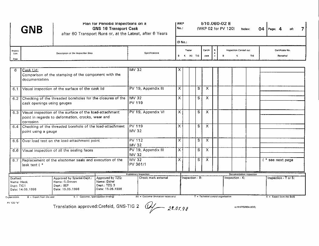
Plan tor Periodic Inspections on a GNS 16 Transport Cask
after 60 Transport Runs or, at the Latest, after 6 Years
WKP
No.:bl0.060-02 E
(WKP 02 for PV 120) Index: 041 Page: 4 of: 7
ID No.:
Inspec- Tester Certiti. R Inspection Carried out Certificate No. tion Description of the Inspection Step Specifications I
B K (K) T/S cate v B K T/S Remarks/ Step
6 Cask Lid: MV 32 X Comparison of the stamping of the component with the
documentation
6.1 Visual inspection of the surface of the cask lid PV 19, Appendix IIl X S X
6.2 Checking of the threaded boreholes for the closures of the MV 32 X S X cask openings using gauges PV 119
6.3 Visual inspection of the surface of the load-attachment PV 19, Appendix VI X S X
point in regards to deformation, cracks, wear and corrosion
6.4 Checking of the threaded borehole of the load-attachment PV 119 X S X
point using a gauge MV 32
6.5 Over load test on the load-attachment point PV 112 X S X MV 32
6.6 Visual inspection of all the sealing faces PV 19, Appendix III X S X MV 32
6.7 Replacement of the elastomer seals and execution of the MV 32 X S X ( * see next page
leak test ( * PV 361/1
Preliminary Inspection Documentation Inspection
Drafted: Approved by Special-Dept.: Approved by TZQ: Check mark external Inspection - 8: Inspection - K: Name: Heck Name: G.Greven Name: Eichel Dept: TIG1 Dept.: BEP Dept.: TZQ 3 Date: 14.05.1998 Date: 15.05.1998 Date: 15.05,1998
8 = Expert from the us et K = Customer, (participation binding) (K) = Customer (invitation necessary)
Translation approved:Crefeld, GNS-TIG 2 2t. Ql.9 f c:/WKP02RO4.DOC;
GNB
Explanations
PV 120 "b"
T - Technical control organisation

GNBPlan for Periodic Inspections on a
GNS 16 Transport Cask after 60 Transport Runs or, at the Latest, after 6 Years
WKP
No.:510.060-02 E
(WKP 02 for PV 120) Index: 04 Page: 5
ID No.:
Inspec. Tester Certifi,. R Inspection Carried out Certificate No.
tion Description of the Inspection Step Specifications ae B K WK T/S Cate v a K T/S Remarks/
Step ... ....
7 Closures of the Cask Openings MV 32 X Comparison of the stamping of the components with the documentation
7.1 Visual inspection of the component surface PV 19, Appendix III X S X
7.2 Visual inspection of the sealing faces PV 19, Appendix III X S X
7.3 Replacement of the elastomer seals and execution of the MV 32 X S X leak test 1* PV 361/1
*It must be ensured that only seals are used which have
been stored according to DIN 7716 and are not older than 10 years'
Preliminary Inspection Documentation Inspection
Drafted: Approved by Special-Dept.: Approved by TZQ: Check mark external Inspection - B: Inspection - K: Inspection - T or S: Name: Heck Name: G.Greven Name: Eichel Dept: TIG1 Dept.: BEP Dept.: TZQ 3 Date: 14.05.1998 Date: 15.05.1998 Date: 15.05.1998
T ' Tecnnical control organisationTer s = l ustomer, (participation indilng GT = Customer (invitation necessary
Translation approved: Cref eld, GNS-TIG 2 q __ ,2 1.0Or. ýd
of: 7
Explanations
PV 120 'b"
B = Expet fom the us S = Expert from tte 8AM
c:/WKPO2R04.DOC;

rian Tor 'erioaic inspections on a GNS 16 Transport Cask
after 60 Transport Runs or, at the Latest, after 6 Years
WKP No.:
bI[U.Ubju-uz t (WKP 02 for PV 120) Index: 04 1 Page: 6 of: 7
ID No.:
Inspec- Tester CerIifi- R inspection Carried out Certificate No.
tion Description of the Inspection Step Specifications a K___________K_____Remarks/ Stp K 4K) T/S cate v B K TIS Remarks/
Step 1 1
8 Basket, MV 32 X
Comparison of the stamping of the components with the documentation
8.1 Visual inspection of the basket in mounted stage; PV 19, Appendix V X S X
random checking of the basket shafts using an endoscope Checking has also to be performed with respect criticality to safety
9 Checking of the Loaded Cask:
9.1 Checking of the shielding function of the cask by AV 25 X S X
evaluating the dose-rate measurement of the last PV 430/2
load and of the first load
9.2 Checking of the heat-dissipation function by evaluating the AV 28 X S X
surface-temperature measurement of the last load and of PV 730/2
the first load
Preliminary Inspection Documentation Inspection
Drafted: Approved by Special-Dept.: Approved by TZQ: Check mark external Inspection - B: Inspection - K: Inspection - T or S:
Name: Heck Name: G.Greven Name: Eichel
Dept: TIG1 Dept.: BEP Dept.: TZQ 3
Date: 14.05.1998 Date: 15.05.1998 Date: 15,05.1998
I it tito er Tpriiptu T iint1oiineE rtI hExplanations 8 = Expert from the user
PV 120 "b"
Translation approved:Crefeld, GNS-TIG 2 6ý2F- Or.o R.-,•"
GNBID No.: i
, , - ustomer nv a on necessary - ec n ca con ro organ sa on xpe (Orn eK - Customer, lprtlicipatlon binding)
c:IWKPO2RO4.DOC;

Plan for Periodic Inspections on a GNS 16 Transport Cask
after 60 Transport Runs or, at the Latest, after 6 Years
WKP
No.:
510.060-02 E (WKP 02 for PV 120) Index: 04 Page: 7
ID No.:
Test Tester Anal- R Inspection Carried out Analysis No. Description of the Test Step Regulations I
Step KB K )K) T/S ysis v a K T/S Remarks/
10 Results of the Periodic Inspection:
10.1 Assessment of the inspection results X S X
10.2 Documentation check of all the above inspections X S X
10.3 Marking of the cask with the date of the next periodic S X inspection and drafting of a comprising certificate
10.4 Approval for further use S X
Translation approved: Crefeld, GNS-TIG 2 '2 9. 011 PIP
GNB of:
PV 120 "b" n:/tig/berichte/WKPO2RO4.DOC;


Plan for Periodic Inspections on Shock Absorbers of a GNS 16 Transport Cask
after 1 5 Transport Runs or, at the Latest, after 3 Years - at the Earliest, prior to the next Transport Run
WKP
No.:510.060-04 E
(WKP 04 for PV 120)
Index: 01 Page: 1 of: 1
ID No.:
Inspec- Tester Certiti- R Inspection Carried out Certificate No. tion Description of the Inspection Step Specification e
B K (K) T/S case v B K T/S Aemarks/ Step I
1 Visual inspection for deformation, wear and Deformation > 25 mm X corrosion deep are undued
Corrosiondefects must be repaired
2 Leak tests on the welding seams PV 117 X X
3 Surface-crack inspection of load-attachment points, PV 24 X X
4 Checking of the bolt- elements PV 119 X X
5 Marking of the shock absorbers with the date of the next X periodic inspection
6 Drafting of a comprising certificate X
Preliminary Inspection Documentation Inspection
Drafted: Approved by Special-Dept.: Approved by TZQ: Check mark external Inspection - B: Inspection - K: Inspection - T or S: Name: Crefeld Name: G.Greven Name: Eberhardt Dept: TIG2 Dept.: BEP Dept.: TZQ 3 Date: 20,03.1998 Date: 23.03.1998 Date: 27.03.1998
Explanations 8 = Expert from the user
PV 120 "b"
K = Customer, (participation binding) (K) - Customer linvitation necessary) T - Technical control organlsation
Translation approved: Crefeld, GNS-TIG 2 q - ,z9.O. 9( 0
S = Expert from the 8AM
c:/WKPO4RO1 .DOC;
GNB

4 P
4.
F
l t\ 4
N#I-
C
Z�kIh
C'
,
� 'N.
I
obo
GIN V.
-Ii
grq- - CJ.-j
rh
0Z
Sir
(r
me
I
A C."