Embed Size (px)
Citation preview
Application Guide
TwinSAFE Version: 1.9.1 Date: 2018-02-05


Table of contents
Application Guide TwinSAFE - version 1.9.1 1
Table of contents
1 Foreword 7
1.1 Notes on the documentation 7
1.1.1 Intended audience 7
1.1.2 Origin of the document 7
1.1.3 Currentness 7
1.1.4 Product features 7
1.1.5 Disclaimer 7
1.1.6 Trademarks 7
1.1.7 Patent Pending 8
1.1.8 Copyright 8
1.1.9 Delivery conditions 8
1.2 Safety instructions 8
1.2.1 Delivery state 8
1.2.2 Operator's obligation to exercise diligence 8
1.2.3 Purpose and area of application 9
1.2.4 Description of safety symbols 9
1.2.5 Explanation of terms 10
1.2.6 Documentation issue status 11
2 Circuit examples 12
2.1 ESTOP function variant 1 (Category 3, PL d) 12
2.1.1 Parameters of the safe input and output terminals 12
2.1.2 Block formation and safety loops 13
2.1.3 Calculation 13
2.2 ESTOP function variant 2 (Category 3, PL d) 17
2.2.1 Parameters of the safe input and output terminals 17
2.2.2 Block formation and safety loops 18
2.2.3 Calculation 18
2.3 ESTOP function variant 3 (Category 4, PL e) 23
2.3.1 Parameters of the safe input and output terminals 23
2.3.2 Block formation and safety loops 24
2.3.3 Calculation 24
2.4 ESTOP function variant 4 (Category 4, PL e) 29
2.4.1 Parameters of the safe input and output terminals 29
2.4.2 Block formation and safety loops 30
2.4.3 Calculation 30

Table of contents
2 Application Guide TwinSAFE - version 1.9.1
2.5 ESTOP function variant 5 (Category 4, PL e) 35
2.5.1 Parameters of the safe input and output terminals 35
2.5.2 Block formation and safety loops 36
2.5.3 Calculation 36
2.6 ESTOP function variant 6 (Category 3, PL d) 41
2.6.1 Parameters of the safe input and output terminals (SIL 2) 41
2.6.2 Block formation and safety loops 42
2.6.3 Calculation 42
2.7 ESTOP function variant 7 (Category 4, PL e) 47
2.7.1 Parameters of the safe input and output terminals 47
2.7.2 Block formation and safety loops 48
2.7.3 Calculation 48
2.8 Protective door function variant 1 (Category 3, PL d) 53
2.8.1 Parameters of the safe input and output terminals 53
2.8.2 Block formation and safety loops 54
2.8.3 Calculation 54
2.9 Protective door function variant 2 (Category 4, PL e) 59
2.9.1 Parameters of the safe input and output terminals 59
2.9.2 Block formation and safety loops 60
2.9.3 Calculation 60
2.10 Protective door function with range monitoring (Category 4, PL e) 65
2.10.1 Parameters of the safe input and output terminals 66
2.10.2 Block formation and safety loops 66
2.10.3 Calculation 67
2.11 Protective door function with guard lock (Category 4, PL e) 72
2.11.1 Parameters of the safe input and output terminals 72
2.11.2 Block formation and safety loops 73
2.11.3 Calculation 73
2.12 Two-hand controller (Category 4, PL e) 79
2.12.1 Parameters of the safe input and output terminals 79
2.12.2 Block formation and safety loops 80
2.12.3 Calculation 80
2.13 Laser scanner (Category 3, PL d) 84
2.13.1 Parameters of the safe input and output terminals 84
2.13.2 Block formation and safety loops 85
2.13.3 Calculation 85

Table of contents
Application Guide TwinSAFE - version 1.9.1 3
2.14 Light grid (Category 4, PL e) 89
2.14.1 Parameters of the safe input and output terminals 89
2.14.2 Block formation and safety loops 90
2.14.3 Calculation 90
2.15 Safety switching mat / safety bumper (Category 4, PL e) 94
2.15.1 Parameters of the safe input and output terminals 94
2.15.2 Block formation and safety loops 95
2.15.3 Calculation 95
2.16 Muting (Category 4, PL e) 99
2.16.1 Parameters of the safe input and output terminals 99
2.16.2 Block formation and safety loops 100
2.16.3 Calculation 100
2.17 All-pole disconnection of a potential group with downstream non-reactive standard terminals (Category 4, PL e) 105
2.17.1 Notes on prevention of feedback 107
2.17.2 Parameters of the safe input and output terminals 109
2.17.3 Block formation and safety loops 110
2.17.4 Calculation 110
2.18 Single-pole disconnection of a potential group with downstream non-reactive standard terminals with fault exclusion (Category 4, PL e) 115
2.18.1 Notes on prevention of feedback 117
2.18.2 Parameters of the safe input and output terminals 119
2.18.3 Block formation and safety loops 120
2.18.4 Calculation 120
2.19 Networked system (Category 4, PL e) 125
2.19.1 Parameters of the safe input and output terminals 126
2.19.2 Block formation and safety loops 126
2.19.3 Calculation 127
2.20 Drive option AX5801 with SS1 stop function (Category 4, PL e) 131
2.20.1 Parameters of the safe input and output terminals 132
2.20.2 Block formation and safety loops 132
2.20.3 Calculation 132
2.21 Drive option AX5805 with SS2 stop function (Category 4, PL e) 137
2.21.1 Parameters of the safe input and output terminals 137
2.21.2 Block formation and safety loops 138
2.21.3 Calculation 138

Table of contents
4 Application Guide TwinSAFE - version 1.9.1
2.22 Direct wiring of the TwinSAFE outputs to TwinSAFE inputs (single-channel) (Category 2, PL c) 142
2.22.1 Parameters of the safe input and output terminals 142
2.22.2 Block formation and safety loops 143
2.22.3 Calculation 143
2.23 Direct wiring of the TwinSAFE outputs to TwinSAFE inputs (dual-channel) (Category 3, PL d) 146
2.23.1 Parameters of the safe input and output terminals 146
2.23.2 Block formation and safety loops 146
2.23.3 Calculation 147
2.24 ESTOP function (Category 3, PL d) 149
2.24.1 Parameters of the safe input and output terminals (SIL 2) 150
2.24.2 Block formation and safety loops 150
2.24.3 Calculation 150
2.25 Speed monitoring (Category 3, PL d) 155
2.25.1 Structure and diagnosis 157
2.25.2 FMEA 157
2.25.3 Parameters of the safe output terminal 159
2.25.4 Block formation and safety loops 159
2.25.5 Calculation 159
2.26 Speed monitoring (via IO-link) (Category 3, PL d) 166
2.26.1 Structure and diagnosis 168
2.26.2 FMEA 168
2.26.3 Parameters of the safe output terminal 170
2.26.4 Block formation and safety loops 170
2.26.5 Calculation 170
2.27 STO function with EL72x1-9014 (Category 3, PL d) 176
2.27.1 Parameters of the safe input and output terminals 177
2.27.2 Block formation and safety loops 178
2.27.3 Safety function 1 178
2.27.4 Calculation 178
2.28 STO-Function with IndraDrive (Category 4, PL e) 182
2.28.1 Parameters of the safe input and output terminals 183
2.28.2 Block formation and safety loops 183
2.28.3 Safety function 1 183
2.28.4 Calculation 183
2.28.5 Technical Note from company Bosch Rexroth AG 188

Table of contents
Application Guide TwinSAFE - version 1.9.1 5
2.29 Temperature measurement with TwinSAFE SC (Category 3, PL d) 192
2.29.1 Diagram of the structure 193
2.29.2 Structure and diagnosis 193
2.29.3 FMEA 193
2.29.4 Parameters of the safe output terminal 195
2.29.5 Block formation and safety loops 195
2.29.6 Calculation 195
2.30 Level measurement with TwinSAFE SC (Category 3, PL d) 202
2.30.1 Diagram of the structure 203
2.30.2 Structure and diagnosis 203
2.30.3 FMEA 203
2.30.4 Parameters of the safe output terminal 205
2.30.5 Block formation and safety-loops 205
2.30.6 Calculation 205
2.31 Pressure measurement with TwinSAFE SC (Category 3, PL d) 212
2.31.1 Diagram of the structure 213
2.31.2 Structure and diagnosis 213
2.31.3 FMEA 213
2.31.4 Parameters of the safe output terminal 215
2.31.5 Block formation and safety-loops 215
2.31.6 Calculation 215
2.32 Monitoring lifting device (Category 3, PL d) 222
2.32.1 Diagram of the structure 223
2.32.2 Structure and diagnosis 223
2.32.3 FMEA 224
2.32.4 Structure within the logic 225
2.32.5 Parameters of the safe output terminal 227
2.32.6 Block formation and safety-loops 228
2.32.7 Calculation 228

Table of contents
6 Application Guide TwinSAFE - version 1.9.1
3 Planning a safety project with TwinSAFE components 235
3.1 Identifying the risks and hazards 235
3.2 Determining the PLr / SIL 236
3.3 Specification of the safety functions 236
3.4 Specification of the measures 236
3.5 Implementation of the safety functions 237
3.6 Proof of achievement of the Performance Level 239
3.7 Validation of the safety functions 239
3.8 Instructions for checking the SF 240
3.9 Acceptance 240
4 Technical report – TÜV SÜD 241
5 Appendix 242
5.1 Beckhoff Support and Service 242
5.1.1 Beckhoff branches and partner companies Beckhoff Support 242
5.1.2 Beckhoff company headquarters 242

Foreword
Application Guide TwinSAFE - version 1.9.1 7
1 Foreword
1.1 Notes on the documentation
1.1.1 Intended audience
This description is only intended for the use of trained specialists in control and automation engineering
who are familiar with the applicable national standards. It is essential that the following notes and
explanations are followed when installing and commissioning these components.
The responsible staff must ensure that the application or use of the products described satisfy all the
requirements for safety, including all the relevant laws, regulations, guidelines and standards.
1.1.2 Origin of the document
This documentation was originally written in German. All other languages are derived from the German
original.
1.1.3 Currentness
Please check whether you are using the current and valid version of this document. The current version
can be downloaded from the Beckhoff homepage at
http://www.beckhoff.de/english/download/twinsafe.htm. In case of doubt, please contact the technical
Support (see chapter 5.1 Beckhoff Support and Service)
1.1.4 Product features
Only the product features specified in the current user documentation are valid. Further information given
on the product pages of the Beckhoff homepage, in emails or in other publications is not authoritative.
1.1.5 Disclaimer
The documentation has been prepared with care. The products described are, however, constantly under
development. For that reason the documentation is not in every case checked for consistency with
performance data, standards or other characteristics.
In the event that it contains technical or editorial errors, we retain the right to make alterations at any time
and without warning.
No claims for the modification of products that have already been supplied may be made on the basis of
the data, diagrams and descriptions in this documentation.
1.1.6 Trademarks
Beckhoff®, TwinCAT®, EtherCAT®, Safety over EtherCAT®, TwinSAFE®, XFC® and XTS® are registered
trademarks of and licensed by Beckhoff Automation GmbH
Other designations used in this publication may be trademarks whose use by third parties for their own
purposes could violate the rights of the owners.

Foreword
8 Application Guide TwinSAFE - version 1.9.1
1.1.7 Patent Pending
The EtherCAT Technology is covered, including but not limited to the following patent applications and
patents: EP1590927, EP1789857, DE102004044764, DE102007017835
with corresponding applications or registrations in various other countries.
The TwinCAT Technology is covered, including but not limited to the following patent applications and
patents: EP0851348, US6167425 with corresponding applications or registrations in various other
countries.
EtherCAT® is registered trademark and patented technology, licensed by Beckhoff Automation GmbH,
Germany
1.1.8 Copyright
© Beckhoff Automation GmbH & Co. KG, Germany.
The reproduction, distribution and utilization of this document as well as the communication of its contents
to others without express authorization are prohibited. Offenders will be held liable for the payment of
damages. All rights reserved in the event of the grant of a patent, utility model or design.
1.1.9 Delivery conditions
In addition, the general delivery conditions of the company Beckhoff Automation GmbH & Co. KG apply.
1.2 Safety instructions
1.2.1 Delivery state
All the components are supplied in particular hardware and software configurations appropriate for the
application. Modifications to hardware or software configurations other than those described in the
documentation are not permitted, and nullify the liability of Beckhoff Automation GmbH & Co. KG.
1.2.2 Operator's obligation to exercise diligence
The operator must ensure that
the TwinSAFE products are only used as intended
the TwinSAFE products are only operated in sound condition and in working order.
the TwinSAFE products are operated only by suitably qualified and authorized personnel.
the personnel is instructed regularly about relevant occupational safety and environmental
protection aspects, and is familiar with the operating instructions and in particular the safety
instructions contained herein.
the operating instructions are in good condition and complete, and always available for reference
at the location where the TwinSAFE products are used.
none of the safety and warning notes attached to the TwinSAFE products are removed, and all
notes remain legible.

Foreword
Application Guide TwinSAFE - version 1.9.1 9
1.2.3 Purpose and area of application
The Application Guide provides the user with examples for the calculation of safety parameters for safety
functions according to the standards DIN EN ISO 13849-1 and EN 62061 or EN 61508:2010 (if
applicable), such as are typically used on machines.
In the examples an EL1904 is taken as an example for a safe input or an EL2904 for a safe output. This
is to be considered an example; of course other safe inputs or outputs can be used, such as an EP1908
or an EL2902. The appropriate parameters, which can be taken from the respective product
documentation, must then be used in the calculation.
Attention
Application samples
These samples provide the user with example calculations. They do not release him from his duty to carry out a risk and hazard analysis and to apply the directives, standards and laws that need to be considered for the application.
1.2.4 Description of safety symbols
The following safety symbols are used in these operating instructions. They are intended to alert the
reader to the associated safety instructions.
DANGER
Serious risk of injury!
Failure to follow the safety instructions associated with this symbol directly endangers the life and health of persons.
WARNING
Caution - Risk of injury!
Failure to follow the safety instructions associated with this symbol endangers the life
and health of persons.
CAUTION
Personal injuries!
Failure to follow the safety instructions associated with this symbol can lead to injuries to persons.
Attention
Damage to the environment or devices
Failure to follow the instructions associated with this symbol can lead to damage to the
environment or equipment.
Note
Tip or pointer
This symbol indicates information that contributes to better understanding.

Foreword
10 Application Guide TwinSAFE - version 1.9.1
1.2.5 Explanation of terms
Designation Explanation
B10D Mean number of cycles after 10% of the components have dangerously failed
CCF Failures with a common cause
dop Mean operating time in days per year
DCavg Average diagnostic coverage
hop Mean operating time in hours per day
MTTFD Mean time to dangerous failure
nop Mean number of annual actuations
PFH Probability of a dangerous failure per hour
PL Performance Level
PLr Required Performance Level
TZyklus Mean time between two successive cycles of the system (given in minutes in the
following examples, but can also be given in seconds)
T1 Lifetime of the device (for TwinSAFE devices typically 20 years)
λD Dangerous failure rate given in FIT (failure rate in 109 component hours)
T10D Operating time - maximum operating time for e.g. electromechanical components
TwinSAFE SC The TwinSAFE SC technology (SC - Single Channel) enables a signal from a
standard terminal to be packaged in a FSoE telegram and transmitted via the
standard fieldbus to the TwinSAFE logic. As a result, falsifications on the
transmission path can be excluded. Within the TwinSAFE logic, this signal is
checked with a second independent signal. With this comparison result, an analog
value is obtained which has typically a level of category 3 and PL d.
This technology does not support digital input signals and cannot be used in a
single-channel structure (only one TwinSAFE SC channel).

Foreword
Application Guide TwinSAFE - version 1.9.1 11
1.2.6 Documentation issue status
Version Comment
1.9.1 Note in chapter 2.17 and 2.18 added
1.9.0 Chapter 2.18 updated
Chapter 3 Planning a safety project added
1.8.0 TwinSAFE SC examples added
Example for Bosch Rexroth IndraDrive drives family
Name SIL2 Communication replaced by TwinSAFE SC
Examples 2.25 and 2.26 updated
General revision of all chapters
1.7.0 Chapter "Direct wiring of the TwinSAFE outputs to TwinSAFE inputs (single
channel)" revised
Preface updated
Chapter "Purpose and area of application" expanded
Structure diagram chapters 2.25 and 2.26 updated
Chapter 2.27 added
Chapters 2.2.3.2, 2.3.3.2, 2.4.3.2, 2.5.3.2, 2.7.3.2 and 2.19.3.2 substantiated
(notes on direct/indirect reading back removed)
Note texts added in chapter 2.19
1.6.2 Letter of conformity updated
Graphics in chapters 2.25 and 2.26 updated
Purpose and area of applications added
1.6.1 Chapters 2.25 and 2.26 added
1.6.0 Chapters 2.17 and 2.18 revised
1.5.0 Company address amended
1.4.0 Chapter 2.24 added
Documentation versions added
Document origin added
Formatting changed
1.3.1 Headers extended with categories and performance levels
Note in Chapter 2.6 moved
1.3.0 Terms of delivery removed
1.2.0 Correction to Chapter 2.6
1.1.0 First released version

Circuit examples
12 Application Guide TwinSAFE - version 1.9.1
2 Circuit examples
2.1 ESTOP function variant 1 (Category 3, PL d)
The emergency stop button is connected via two normally closed contacts to an EL1904 safe input
terminal. The testing and the monitoring of the discrepancy of the two signals are activated. The restart
and the feedback signal are wired to standard terminals and are transferred to TwinSAFE via the
standard PLC. The contactors K1 and K2 are connected in parallel to the safe output. Current
measurement and testing of the output are active for this circuit.
Restart
K1
K2
Emergency stop
button
K1 K2
Logical connection in
the EL6900
S1
S2
2.1.1 Parameters of the safe input and output terminals
EL1904
Parameter Value
Sensor test channel 1 active Yes
Sensor test channel 2 active Yes
Sensor test channel 3 active Yes
Sensor test channel 4 active Yes
Logic channel 1 and 2 Single Logic
Logic channel 3 and 4 Single Logic
EL2904
Parameter Value
Current measurement active Yes
Output test pulses active Yes

Circuit examples
Application Guide TwinSAFE - version 1.9.1 13
2.1.2 Block formation and safety loops
2.1.2.1 Safety function 1
2.1.3 Calculation
2.1.3.1 PFH / MTTFd /B10d – values
Component Value
EL1904 – PFH 1.11E-09
EL2904 – PFH 1.25E-09
EL6900 – PFH 1.03E-09
S1 – B10d 100,000
S2 – B10d 10,000,000
K1 – B10d 1,300,000
K2 – B10d 1,300,000
Days of operation (dop) 230
Hours of operation / day (hop) 16
Cycle time (minutes) (TZyklus) 10080 (1x per week) (7 days, 24 hours)
Lifetime (T1) 20 years = 175200 hours
2.1.3.2 Diagnostic Coverage DC
Component Value
S1 with testing/plausibility DCavg=99%
K1/K2 with testing and EDM (actuation 1x per week) DCavg=60%
K1/K2 with testing and EDM (actuation 1x per shift) DCavg=90%
2.1.3.3 Calculation for safety function 1
Calculation of the PFH and MTTFd values from the B10d values:
From:
𝑛𝑜𝑝 =𝑑𝑜𝑝∗ℎ𝑜𝑝∗60
𝑇𝑍𝑦𝑘𝑙𝑢𝑠
and:
𝑀𝑇𝑇𝐹𝑑 =𝐵10𝑑
0,1 ∗ 𝑛𝑜𝑝
S1 EL1904 EL6900 EL2904
K1
K2
Circuit examples
14 Application Guide TwinSAFE - version 1.9.1
Inserting the values, this produces:
S1:
𝑛𝑜𝑝 =230∗16∗60
10080= 21,90
𝑀𝑇𝑇𝐹𝑑 =100000
0,1∗21,90= 45662,1y = 399999120h
K1/K2:
𝑛𝑜𝑝 =230∗16∗60
10080= 21,90
𝑀𝑇𝑇𝐹𝑑 =1300000
0,1 ∗ 21,90= 593607,3y = 5199997320h
and the assumption that S1, K1 and K2 are each single-channel:
𝑀𝑇𝑇𝐹𝑑 =1
𝜆𝑑
produces for
𝑃𝐹𝐻 =0,1 ∗ 𝑛𝑜𝑝 ∗ (1 − 𝐷𝐶)
𝐵10𝑑=
1 − DC
MTTFd
S1:
𝑃𝐹𝐻 =1 − 0,99
45662,1 ∗ 8760= 2,50E − 11
K1/K2: actuation 1x per week
𝑃𝐹𝐻 =1 − 0,60
593607,3 ∗ 8760= 7,69E − 11
K1/K2: actuation 1x per shift
𝑃𝐹𝐻 =1 − 0,90
593607,3 ∗ 8760= 1,92E − 11
The following assumptions must now be made:
Safety switch S1: According to BIA report 2/2008, error exclusion to up 100,000 cycles is possible, provided
the manufacturer has confirmed this. If no confirmation exists, S1 is included in the calculation as follows.
Relays K1 and K2 are both connected to the safety function. The non-functioning of a relay does not lead
to a dangerous situation, but it is discovered by the feedback. Furthermore, the B10d values for K1 and
K2 are identical.
There is a coupling coefficient between the components that are connected via two channels. Examples
are temperature, EMC, voltage peaks or signals between these components. This is assumed to be the
worst-case estimation, where ß =10%. EN 62061 contains a table with which this ß-factor can be
precisely determined. Further, it is assumed that all usual measures have been taken to prevent both
channels failing unsafely at the same time due to an error (e.g. overcurrent through relay contacts,
overtemperature in the control cabinet).
This produces for the calculation of the PFH value for safety function 1:

Circuit examples
Application Guide TwinSAFE - version 1.9.1 15
𝑃𝐹𝐻𝑔𝑒𝑠 = 𝑃𝐹𝐻(𝑆1) + 𝑃𝐹𝐻(𝐸𝐿1904) + 𝑃𝐹𝐻(𝐸𝐿6900) + 𝑃𝐹𝐻(𝐸𝐿2904) + 𝛽 ∗𝑃𝐹𝐻(𝐾1) + 𝑃𝐹𝐻(𝐾2)
2+ (1 − 𝛽)2 ∗ (𝑃𝐹𝐻(𝐾1) ∗ 𝑃𝐹𝐻(𝐾2)) ∗ 𝑇1
Since the portion (1 − 𝛽)2 ∗ (𝑃𝐹𝐻(𝐾1) ∗ 𝑃𝐹𝐻(𝐾2)) ∗ 𝑇1 is smaller than the rest by the power of ten, it is
neglected in this and all further calculations for the purpose of simplification.
to:
𝑃𝐹𝐻𝑔𝑒𝑠 = 2,5𝐸 − 11 + 1,11𝐸 − 09 + 1,03𝐸 − 09 + 1,25𝐸 − 09 + 10% ∗7,96𝐸 − 11 + 7,96𝐸 − 11
2= 3,42𝐸 − 09
in the case of actuation 1x per week
or:
𝑃𝐹𝐻𝑔𝑒𝑠 = 2,5𝐸 − 11 + 1,11𝐸 − 09 + 1,03𝐸 − 09 + 1,25𝐸 − 09 + 10% ∗1,92𝐸 − 11 + 1,92𝐸 − 11
2= 3,42𝐸 − 09
in the case of actuation 1x per shift
The MTTFd value for safety function 1 (based on the same assumption) is calculated with:
1
𝑀𝑇𝑇𝐹𝑑 𝑔𝑒𝑠
= ∑1
𝑀𝑇𝑇𝐹𝑑 𝑛
𝑛
𝑖=1
as:
1
𝑀𝑇𝑇𝐹𝑑 𝑔𝑒𝑠
=1
𝑀𝑇𝑇𝐹𝑑 (𝑆1)+
1
𝑀𝑇𝑇𝐹 𝑑(𝐸𝐿1904)+
1
𝑀𝑇𝑇𝐹𝑑 (𝐸𝐿6900)+
1
𝑀𝑇𝑇𝐹 𝑑(𝐸𝐿2904)+
1
(𝑀𝑇𝑇𝐹𝑑 (𝐾1))
with:
𝑀𝑇𝑇𝐹𝑑(S1) =𝐵10𝑑(𝑆1)
0,1 ∗ 𝑛𝑜𝑝
𝑀𝑇𝑇𝐹𝑑(K1) =𝐵10𝑑(𝐾1)
0,1 ∗ 𝑛𝑜𝑝
If only PFH values are available for EL1904, EL2904 and EL6900, the following estimation applies:
𝑀𝑇𝑇𝐹𝑑(ELxxxx) =(1 − 𝐷𝐶(𝐸𝐿𝑥𝑥𝑥))
𝑃𝐹𝐻(𝐸𝐿𝑥𝑥𝑥)
Hence:
𝑀𝑇𝑇𝐹𝑑(EL1904) =(1 − 𝐷𝐶(𝐸𝐿1904))
𝑃𝐹𝐻(𝐸𝐿1904)=
(1 − 0,99)
1,11E − 09 1
h∗ 8760h
y
=0,01
9,72E − 061
y
= 1028,8y
𝑀𝑇𝑇𝐹𝑑(EL6900) =(1 − 𝐷𝐶(𝐸𝐿6900))
𝑃𝐹𝐻(𝐸𝐿6900) =
(1 − 0,99)
1,03E − 091
h∗ 8760h
y
=0,01
9,02E − 061
y
= 1108,6y

Circuit examples
16 Application Guide TwinSAFE - version 1.9.1
𝑀𝑇𝑇𝐹𝑑(EL2904) =(1 − 𝐷𝐶(𝐸𝐿2904))
𝑃𝐹𝐻(𝐸𝐿2904)=
(1 − 0,99)
1,25E − 09 1
h∗ 8760h
y
=0,01
1,1E − 051
y
= 913,2y
𝑀𝑇𝑇𝐹𝐷𝑔𝑒𝑠 =1
1
45662,1𝑦+
1
1028,8𝑦+
1
1108,6𝑦+
1
913,2𝑦+
1
593607,3𝑦
= 333,98𝑦
𝐷𝐶𝑎𝑣𝑔 =
99%
45662,1+
99%
1028,8+
99%
1108,6+
99%
913,2+
60%
593607,3+
60%
593607,31
45662,1+
1
1028,8+
1
1108,6+
1
913,2+
1
593607,3+
1
593607,3
= 98,96%
bzw.:
𝐷𝐶𝑎𝑣𝑔 =
99%
45662,1+
99%
1028,8+
99%
1108,6+
99%
913,2+
90%
593607,3+
90%
593607,31
45662,1+
1
1028,8+
1
1108,6+
1
913,2+
1
593607,3+
1
593607,3
= 98,99%
CAUTION
Measures for attaining category 3!
This structure is possible up to category 3 at the most, since an error in the feedback path of the relays may be undiscovered. In order to attain category 3, all rising and falling edges must be evaluated together with the time dependence in the controller for the feedback expectation!
CAUTION
Implement a restart lock in the machine!
The restart lock is NOT part of the safety chain and must be implemented in the machine!
MTTFd Designation for each channel Range for each channel
low 3 years ≤ MTTFd < 10 years
medium 10 years ≤ MTTFd < 30 years
high 30 years ≤ MTTFd ≤ 100 years
DCavg Designation Range
none DC < 60 %
low 60 % ≤ DC < 90 %
medium 90 % ≤ DC < 99 %
high 99 % ≤ DC
Category B 1 2 2 3 3 4
DC
MTTFd
none none low medium low medium high
low a - a b b c -
medium b - b c c d -
high - c c d d d e
Circuit examples
Application Guide TwinSAFE - version 1.9.1 17
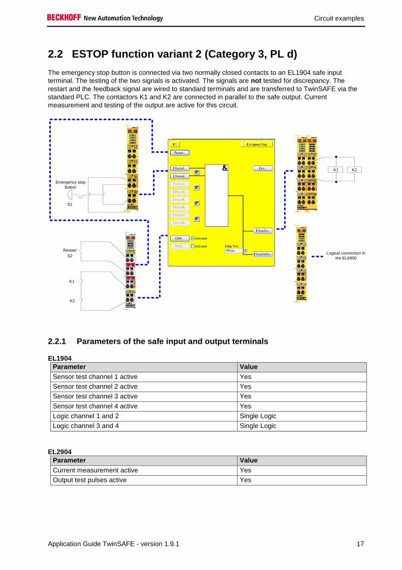
2.2 ESTOP function variant 2 (Category 3, PL d)
The emergency stop button is connected via two normally closed contacts to an EL1904 safe input
terminal. The testing of the two signals is activated. The signals are not tested for discrepancy. The
restart and the feedback signal are wired to standard terminals and are transferred to TwinSAFE via the
standard PLC. The contactors K1 and K2 are connected in parallel to the safe output. Current
measurement and testing of the output are active for this circuit.
Restart
K1
K2
Emergency stop
button
Logical connection in
the EL6900
K1 K2
S1
S2
2.2.1 Parameters of the safe input and output terminals
EL1904
Parameter Value
Sensor test channel 1 active Yes
Sensor test channel 2 active Yes
Sensor test channel 3 active Yes
Sensor test channel 4 active Yes
Logic channel 1 and 2 Single Logic
Logic channel 3 and 4 Single Logic
EL2904
Parameter Value
Current measurement active Yes
Output test pulses active Yes

Circuit examples
18 Application Guide TwinSAFE - version 1.9.1
2.2.2 Block formation and safety loops
2.2.2.1 Safety function 1
2.2.3 Calculation
2.2.3.1 PFH / MTTFd /B10d – values
Component Value
EL1904 – PFH 1.11E-09
EL2904 – PFH 1.25E-09
EL6900 – PFH 1.03E-09
S1 – B10d 100,000
S2 – B10d 10,000,000
K1 – B10d 1,300,000
K2 – B10d 1,300,000
Days of operation (dop) 230
Hours of operation / day (hop) 16
Cycle time (minutes) (TZyklus) 10080 (1x per week)
Lifetime (T1) 20 years = 175200 hours
2.2.3.2 Diagnostic Coverage DC
Component Value
S1 with testing / without plausibility DCavg=90%
K1/K2 with testing and EDM
(actuation 1x per week)
DCavg=60%
K1/K2 with testing and EDM
(actuation 1x per shift)
DCavg=90%
2.2.3.3 Calculation for block 1
Calculation of the PFH and MTTFd values from the B10d values:
From:
𝑛𝑜𝑝 =𝑑𝑜𝑝∗ℎ𝑜𝑝∗60
𝑇𝑍𝑦𝑘𝑙𝑢𝑠
and:
S1 EL1904 EL6900 EL2904
K1
K2

Circuit examples
Application Guide TwinSAFE - version 1.9.1 19
𝑀𝑇𝑇𝐹𝑑 =𝐵10𝑑
0,1 ∗ 𝑛𝑜𝑝
Inserting the values, this produces:
S1:
𝑛𝑜𝑝 =230∗16∗60
10080= 21,90
𝑀𝑇𝑇𝐹𝑑 =100000
0,1∗21,90= 45662,1y = 399999120h
K1/K2:
𝑛𝑜𝑝 =230∗16∗60
10080= 21,90
𝑀𝑇𝑇𝐹𝑑 =1300000
0,1 ∗ 21,90= 593607,3y = 5199997320h
and the assumption that S1, K1 and K2 are each single-channel:
𝑀𝑇𝑇𝐹𝑑 =1
𝜆𝑑
produces for
𝑃𝐹𝐻 =0,1 ∗ 𝑛𝑜𝑝 ∗ (1 − 𝐷𝐶)
𝐵10𝑑=
1 − DC
MTTFd
S1:
𝑃𝐹𝐻 =1 − 0,90
45662,1 ∗ 8760= 2,50E − 10
K1/K2: actuation 1x per week
𝑃𝐹𝐻 =1 − 0,60
593607,3 ∗ 8760= 7,69E − 11
K1/K2: actuation 1x per shift
𝑃𝐹𝐻 =1 − 0,90
593607,3 ∗ 8760= 1,92E − 11
The following assumptions must now be made:
Safety switch S1: According to BIA report 2/2008, error exclusion to up 100,000 cycles is possible, provided
the manufacturer has confirmed this. If no confirmation exists, S1 is included in the calculation as follows.
Relays K1 and K2 are both connected to the safety function. The non-functioning of a relay does not lead
to a dangerous situation, but it is discovered by the feedback. Furthermore, the B10d values for K1 and
K2 are identical.

Circuit examples
20 Application Guide TwinSAFE - version 1.9.1
There is a coupling coefficient between the components that are connected via two channels. Examples
are temperature, EMC, voltage peaks or signals between these components. This is assumed to be the
worst-case estimation, where ß =10%. EN 62061 contains a table with which this ß-factor can be
precisely determined. Further, it is assumed that all usual measures have been taken to prevent both
channels failing unsafely at the same time due to an error (e.g. overcurrent through relay contacts,
overtemperature in the control cabinet).
This produces for the calculation of the PFH value for block 1:
𝑃𝐹𝐻𝑔𝑒𝑠 = 𝑃𝐹𝐻(𝑆1) + 𝑃𝐹𝐻(𝐸𝐿1904) + 𝑃𝐹𝐻(𝐸𝐿6900) + 𝑃𝐹𝐻(𝐸𝐿2904) + 𝛽 ∗𝑃𝐹𝐻(𝐾1) + 𝑃𝐹𝐻(𝐾2)
2+ (1 − 𝛽)2 ∗ (𝑃𝐹𝐻(𝐾1) ∗ 𝑃𝐹𝐻(𝐾2)) ∗ 𝑇1
Since the portion (1 − 𝛽)2 ∗ (𝑃𝐹𝐻(𝐾1) ∗ 𝑃𝐹𝐻(𝐾2)) ∗ 𝑇1 is smaller than the rest by the power of ten, it is
neglected in this and all further calculations for the purpose of simplification.
to:
𝑃𝐹𝐻𝑔𝑒𝑠 = 2,5𝐸 − 10 + 1,11𝐸 − 09 + 1,03𝐸 − 09 + 1,25𝐸 − 09 + 10% ∗7,96𝐸 − 11 + 7,96𝐸 − 11
2= 3,65𝐸 − 09
in the case of actuation 1x per week
or:
𝑃𝐹𝐻𝑔𝑒𝑠 = 2,5𝐸 − 10 + 1,11𝐸 − 09 + 1,03𝐸 − 09 + 1,25𝐸 − 09 + 10% ∗1,92𝐸 − 11 + 1,92𝐸 − 11
2= 3,65𝐸 − 09
in the case of actuation 1x per shift
The MTTFd value for safety function 1 (based on the same assumption) is calculated with:
1
𝑀𝑇𝑇𝐹𝑑 𝑔𝑒𝑠
= ∑1
𝑀𝑇𝑇𝐹𝑑 𝑛
𝑛
𝑖=1
as:
1
𝑀𝑇𝑇𝐹𝑑 𝑔𝑒𝑠
=1
𝑀𝑇𝑇𝐹𝑑 (𝑆1)+
1
𝑀𝑇𝑇𝐹𝑑(𝐸𝐿1904)+
1
𝑀𝑇𝑇𝐹𝑑 (𝐸𝐿6900)+
1
𝑀𝑇𝑇𝐹𝑑(𝐸𝐿2904)+
1
𝑀𝑇𝑇𝐹𝑑 (𝐾1)
with:
𝑀𝑇𝑇𝐹𝑑(S1) =𝐵10𝑑(𝑆1)
0,1 ∗ 𝑛𝑜𝑝
𝑀𝑇𝑇𝐹𝑑(K1) =𝐵10𝑑(𝐾1)
0,1 ∗ 𝑛𝑜𝑝
Circuit examples
Application Guide TwinSAFE - version 1.9.1 21
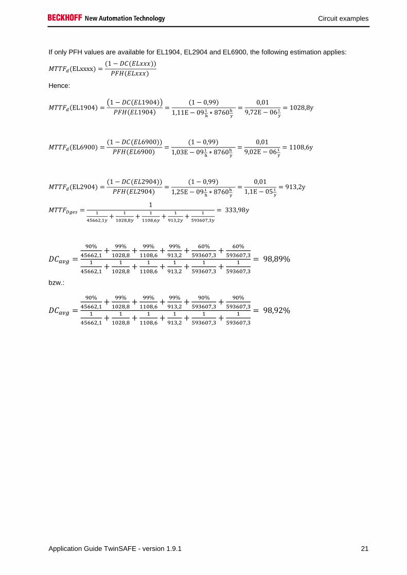
If only PFH values are available for EL1904, EL2904 and EL6900, the following estimation applies:
𝑀𝑇𝑇𝐹𝑑(ELxxxx) =(1 − 𝐷𝐶(𝐸𝐿𝑥𝑥𝑥))
𝑃𝐹𝐻(𝐸𝐿𝑥𝑥𝑥)
Hence:
𝑀𝑇𝑇𝐹𝑑(EL1904) =(1 − 𝐷𝐶(𝐸𝐿1904))
𝑃𝐹𝐻(𝐸𝐿1904)=
(1 − 0,99)
1,11E − 09 1
h∗ 8760h
y
=0,01
9,72E − 061
y
= 1028,8y
𝑀𝑇𝑇𝐹𝑑(EL6900) =(1 − 𝐷𝐶(𝐸𝐿6900))
𝑃𝐹𝐻(𝐸𝐿6900) =
(1 − 0,99)
1,03E − 091
h∗ 8760h
y
=0,01
9,02E − 061
y
= 1108,6y
𝑀𝑇𝑇𝐹𝑑(EL2904) =(1 − 𝐷𝐶(𝐸𝐿2904))
𝑃𝐹𝐻(𝐸𝐿2904) =
(1 − 0,99)
1,25E − 091
h∗ 8760h
y
=0,01
1,1E − 051
y
= 913,2y
𝑀𝑇𝑇𝐹𝐷𝑔𝑒𝑠 =1
1
45662,1𝑦+
1
1028,8𝑦+
1
1108,6𝑦+
1
913,2𝑦+
1
593607,3𝑦
= 333,98𝑦
𝐷𝐶𝑎𝑣𝑔 =
90%
45662,1+
99%
1028,8+
99%
1108,6+
99%
913,2+
60%
593607,3+
60%
593607,31
45662,1+
1
1028,8+
1
1108,6+
1
913,2+
1
593607,3+
1
593607,3
= 98,89%
bzw.:
𝐷𝐶𝑎𝑣𝑔 =
90%
45662,1+
99%
1028,8+
99%
1108,6+
99%
913,2+
90%
593607,3+
90%
593607,31
45662,1+
1
1028,8+
1
1108,6+
1
913,2+
1
593607,3+
1
593607,3
= 98,92%

Circuit examples
22 Application Guide TwinSAFE - version 1.9.1
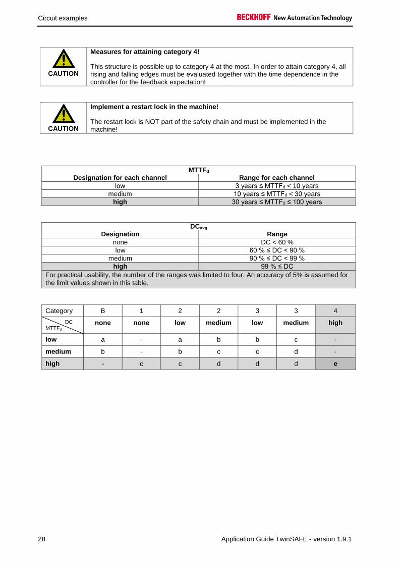
CAUTION
Measures for attaining category 3!
This structure is possible only up to category 3 at the most on account of a possible sleeping error. In order to attain category 3, all rising and falling edges must be evaluated together with the time dependence in the controller for the feedback expectation!
CAUTION
Implement a restart lock in the machine!
The restart lock is NOT part of the safety chain and must be implemented in the machine!
MTTFd Designation for each channel Range for each channel
low 3 years ≤ MTTFd < 10 years
medium 10 years ≤ MTTFd < 30 years
high 30 years ≤ MTTFd ≤ 100 years
DCavg Designation Range
none DC < 60 %
low 60 % ≤ DC < 90 %
medium 90 % ≤ DC < 99 %
high 99 % ≤ DC
Category B 1 2 2 3 3 4
DC MTTFd
none none low medium low medium high
low a - a b b c -
medium b - b c c d -
high - c c d d d e

Circuit examples
Application Guide TwinSAFE - version 1.9.1 23
2.3 ESTOP function variant 3 (Category 4, PL e)
The emergency stop button is connected via two normally closed contacts to an EL1904 safe input
terminal. The testing of the two signals is activated. These signals are checked for discrepancy. The
restart and the feedback signal are wired to standard terminals and are transferred to TwinSAFE via the
standard PLC. Furthermore, the output of the ESTOP function block and the feedback signal are wired to
an EDM block. This checks that the feedback signal assumes the opposing state of the ESTOP output
within the set time.
The contactors K1 and K2 are connected in parallel to the safe output. Current measurement and testing
of the output are active for this circuit.
Restart
K1
K2
Emergency stop
button
Logical connection in
the EL6900
K1 K2
S1
S2
2.3.1 Parameters of the safe input and output terminals
EL1904
Parameter Value
Sensor test channel 1 active Yes
Sensor test channel 2 active Yes
Sensor test channel 3 active Yes
Sensor test channel 4 active Yes
Logic channel 1 and 2 Single Logic
Logic channel 3 and 4 Single Logic

Circuit examples
24 Application Guide TwinSAFE - version 1.9.1
EL2904
Parameter Value
Current measurement active Yes
Output test pulses active Yes
2.3.2 Block formation and safety loops
2.3.2.1 Block 1
2.3.3 Calculation
2.3.3.1 PFH / MTTFd /B10d – values
Component Value
EL1904 – PFH 1.11E-09
EL2904 – PFH 1.25E-09
EL6900 – PFH 1.03E-09
S1 – B10d 100,000
S2 – B10d 10,000,000
K1 – B10d 1,300,000
K2 – B10d 1,300,000
Days of operation (dop) 230
Hours of operation / day (hop) 16
Cycle time (minutes) (TZyklus) 10080 (1x per week)
Lifetime (T1) 20 years = 175200 hours
2.3.3.2 Diagnostic Coverage DC
Component Value
S1 with testing/plausibility DCavg=99%
K1/K2 with testing and EDM
(actuation 1x per week)
DCavg=90%
K1/K2 with testing and EDM
(actuation 1x per shift)
DCavg=99%
S1 EL1904 EL6900 EL2904
K1
K2

Circuit examples
Application Guide TwinSAFE - version 1.9.1 25
2.3.3.3 Calculation for safety function 1
Calculation of the PFH and MTTFd values from the B10d values:
From:
𝑛𝑜𝑝 =𝑑𝑜𝑝∗ℎ𝑜𝑝∗60
𝑇𝑍𝑦𝑘𝑙𝑢𝑠
and:
𝑀𝑇𝑇𝐹𝑑 =𝐵10𝑑
0,1 ∗ 𝑛𝑜𝑝
Inserting the values, this produces:
S1:
𝑛𝑜𝑝 =230∗16∗60
10080= 21,90
𝑀𝑇𝑇𝐹𝑑 =100000
0,1∗21,90= 45662,1y = 399999120h
K1/K2:
𝑛𝑜𝑝 =230∗16∗60
10080= 21,90
𝑀𝑇𝑇𝐹𝑑 =1300000
0,1 ∗ 21,90= 593607,3y = 5199997320h
and the assumption that S1, K1 and K2 are each single-channel:
𝑀𝑇𝑇𝐹𝑑 =1
𝜆𝑑
produces for
𝑃𝐹𝐻 =0,1 ∗ 𝑛𝑜𝑝 ∗ (1 − 𝐷𝐶)
𝐵10𝑑=
1 − DC
MTTFd
S1:
𝑃𝐹𝐻 =1 − 0,99
45662,1 ∗ 8760= 2,50E − 11
K1/K2: actuation 1x per week
𝑃𝐹𝐻 =1 − 0,90
593607,3 ∗ 8760= 1,92E − 11
K1/K2: actuation 1x per shift
𝑃𝐹𝐻 =1 − 0,99
593607,3 ∗ 8760= 1,92E − 12

Circuit examples
26 Application Guide TwinSAFE - version 1.9.1
The following assumptions must now be made:
Safety switch S1: According to BIA report 2/2008, error exclusion to up 100,000 cycles is possible, provided
the manufacturer has confirmed this. If no confirmation exists, S1 is included in the calculation as follows.
Relays K1 and K2 are both connected to the safety function. The non-functioning of a relay does not lead
to a dangerous situation, but it is discovered by the feedback. Furthermore, the B10d values for K1 and
K2 are identical.
There is a coupling coefficient between the components that are connected via two channels. Examples
are temperature, EMC, voltage peaks or signals between these components. This is assumed to be the
worst-case estimation, where ß =10%. EN 62061 contains a table with which this ß-factor can be
precisely determined. Further, it is assumed that all usual measures have been taken to prevent both
channels failing unsafely at the same time due to an error (e.g. overcurrent through relay contacts,
overtemperature in the control cabinet).
This produces for the calculation of the PFH value for safety function 1:
𝑃𝐹𝐻𝑔𝑒𝑠 = 𝑃𝐹𝐻(𝑆1) + 𝑃𝐹𝐻(𝐸𝐿1904) + 𝑃𝐹𝐻(𝐸𝐿6900) + 𝑃𝐹𝐻(𝐸𝐿2904) + 𝛽 ∗𝑃𝐹𝐻(𝐾1) + 𝑃𝐹𝐻(𝐾2)
2+ (1 − 𝛽)2 ∗ (𝑃𝐹𝐻(𝐾1) ∗ 𝑃𝐹𝐻(𝐾2)) ∗ 𝑇1
Since the portion (1 − 𝛽)2 ∗ (𝑃𝐹𝐻(𝐾1) ∗ 𝑃𝐹𝐻(𝐾2)) ∗ 𝑇1 is smaller than the rest by the power of ten, it is
neglected in this and all further calculations for the purpose of simplification.
to:
𝑃𝐹𝐻𝑔𝑒𝑠 = 2,5𝐸 − 11 + 1,11𝐸 − 09 + 1,03𝐸 − 09 + 1,25𝐸 − 09 + 10% ∗1,92𝐸 − 11 + 1,92𝐸 − 11
2= 3,42𝐸 − 09
in the case of actuation 1x per week
or
𝑃𝐹𝐻𝑔𝑒𝑠 = 2,5𝐸 − 11 + 1,11𝐸 − 09 + 1,03𝐸 − 09 + 1,25𝐸 − 09 + 10% ∗1,92𝐸 − 12 + 1,92𝐸 − 12
2= 3,42𝐸 − 09
in the case of actuation 1x per shift

Circuit examples
Application Guide TwinSAFE - version 1.9.1 27
The MTTFd value for safety function 1 (based on the same assumption) is calculated with:
1
𝑀𝑇𝑇𝐹𝑑 𝑔𝑒𝑠
= ∑1
𝑀𝑇𝑇𝐹𝑑 𝑛
𝑛
𝑖=1
as:
1
𝑀𝑇𝑇𝐹𝑑 𝑔𝑒𝑠
=1
𝑀𝑇𝑇𝐹𝑑 (𝑆1)+
1
𝑀𝑇𝑇𝐹𝑑(𝐸𝐿1904)+
1
𝑀𝑇𝑇𝐹𝑑 (𝐸𝐿6900)+
1
𝑀𝑇𝑇𝐹𝑑(𝐸𝐿2904)+
1
𝑀𝑇𝑇𝐹𝑑 (𝐾1)
with:
𝑀𝑇𝑇𝐹𝑑(S1) =𝐵10𝑑(𝑆1)
0,1 ∗ 𝑛𝑜𝑝
𝑀𝑇𝑇𝐹𝑑(K1) =𝐵10𝑑(𝐾1)
0,1 ∗ 𝑛𝑜𝑝
If only PFH values are available for EL1904, EL2904 and EL6900, the following estimation applies:
𝑀𝑇𝑇𝐹𝑑(ELxxxx) =(1 − 𝐷𝐶(𝐸𝐿𝑥𝑥𝑥))
𝑃𝐹𝐻(𝐸𝐿𝑥𝑥𝑥)
Hence:
𝑀𝑇𝑇𝐹𝑑(EL1904) =(1 − 𝐷𝐶(𝐸𝐿1904))
𝑃𝐹𝐻(𝐸𝐿1904)=
(1 − 0,99)
1,11E − 09 1
h∗ 8760h
y
=0,01
9,72E − 061
y
= 1028,8y
𝑀𝑇𝑇𝐹𝑑(EL6900) =(1 − 𝐷𝐶(𝐸𝐿6900))
𝑃𝐹𝐻(𝐸𝐿6900) =
(1 − 0,99)
1,03E − 091
h∗ 8760h
y
=0,01
9,02E − 061
y
= 1108,6y
𝑀𝑇𝑇𝐹𝑑(EL2904) =(1 − 𝐷𝐶(𝐸𝐿2904))
𝑃𝐹𝐻(𝐸𝐿2904) =
(1 − 0,99)
1,25E − 091
h∗ 8760h
y
=0,01
1,1E − 051
y
= 913,2y
𝑀𝑇𝑇𝐹𝐷𝑔𝑒𝑠 =1
1
45662,1𝑦+
1
1028,8𝑦+
1
1108,6𝑦+
1
913,2𝑦+
1
593607,3𝑦
= 333,98𝑦
𝐷𝐶𝑎𝑣𝑔 =
99%
45662,1+
99%
1028,8+
99%
1108,6+
99%
913,2+
90%
593607,3+
90%
593607,31
45662,1+
1
1028,8+
1
1108,6+
1
913,2+
1
593607,3+
1
593607,3
= 98,99%
or:
𝐷𝐶𝑎𝑣𝑔 =
99%
45662,1+
99%
1028,8+
99%
1108,6+
99%
913,2+
99%
593607,3+
99%
593607,31
45662,1+
1
1028,8+
1
1108,6+
1
913,2+
1
593607,3+
1
593607,3
= 99,00%
Circuit examples
28 Application Guide TwinSAFE - version 1.9.1
CAUTION
Measures for attaining category 4!
This structure is possible up to category 4 at the most. In order to attain category 4, all rising and falling edges must be evaluated together with the time dependence in the controller for the feedback expectation!
CAUTION
Implement a restart lock in the machine!
The restart lock is NOT part of the safety chain and must be implemented in the machine!
MTTFd Designation for each channel Range for each channel
low 3 years ≤ MTTFd < 10 years
medium 10 years ≤ MTTFd < 30 years
high 30 years ≤ MTTFd ≤ 100 years
DCavg Designation Range
none DC < 60 %
low 60 % ≤ DC < 90 %
medium 90 % ≤ DC < 99 %
high 99 % ≤ DC
For practical usability, the number of the ranges was limited to four. An accuracy of 5% is assumed for
the limit values shown in this table.
Category B 1 2 2 3 3 4
DC MTTFd
none none low medium low medium high
low a - a b b c -
medium b - b c c d -
high - c c d d d e

Circuit examples
Application Guide TwinSAFE - version 1.9.1 29
2.4 ESTOP function variant 4 (Category 4, PL e)
The emergency stop button with two normally closed contacts, the restart and the feedback loop are
connected to safe channels of an EL1904 input terminal. The testing of the signals is activated. The two
emergency stop signals are tested for discrepancy. The contactors K1 and K2 are connected in parallel to
the safe output. Current measurement and testing of the output are active for this circuit.
Emergency stop
button
Restart
K1
K2
Logical connection in
the EL6900
K1 K2
S1
S2
2.4.1 Parameters of the safe input and output terminals
EL1904 (applies to all EL1904 used)
Parameter Value
Sensor test channel 1 active Yes
Sensor test channel 2 active Yes
Sensor test channel 3 active Yes
Sensor test channel 4 active Yes
Logic channel 1 and 2 Single Logic
Logic channel 3 and 4 Single Logic
EL2904
Parameter Value
Current measurement active Yes
Output test pulses active Yes

Circuit examples
30 Application Guide TwinSAFE - version 1.9.1
2.4.2 Block formation and safety loops
2.4.2.1 Safety function 1
2.4.3 Calculation
2.4.3.1 PFH / MTTFd /B10d – values
Component Value
EL1904 – PFH 1.11E-09
EL2904 – PFH 1.25E-09
EL6900 – PFH 1.03E-09
S1 – B10d 100,000
S2 – B10d 10,000,000
K1 – B10d 1,300,000
K2 – B10d 1,300,000
Days of operation (dop) 230
Hours of operation / day (hop) 16
Cycle time (minutes) (TZyklus) 10080 (1x per week)
Lifetime (T1) 20 years = 175200 hours
2.4.3.2 Diagnostic Coverage DC
Component Value
S1 with testing/plausibility DCavg=99%
S2 with plausibility DCavg=90%
K1/K2 with testing and EDM
(actuation 1x per shift)
DCavg=99%
2.4.3.3 Calculation for safety function 1
Calculation of the PFH and MTTFd values from the B10d values:
From:
𝑛𝑜𝑝 =𝑑𝑜𝑝∗ℎ𝑜𝑝∗60
𝑇𝑍𝑦𝑘𝑙𝑢𝑠
and:
𝑀𝑇𝑇𝐹𝑑 =𝐵10𝑑
0,1 ∗ 𝑛𝑜𝑝
S1 EL1904 EL6900 EL2904
K1
K2
S2 EL1904

Circuit examples
Application Guide TwinSAFE - version 1.9.1 31
Inserting the values, this produces:
S1:
𝑛𝑜𝑝 =230∗16∗60
10080= 21,90
𝑀𝑇𝑇𝐹𝑑 =100000
0,1∗21,90= 45662,1y = 399999120h
S2:
𝑛𝑜𝑝 =230∗16∗60
10080= 21,90
𝑀𝑇𝑇𝐹𝑑 =10000000
0,1∗21,90= 4566210,0y = 4E10h
K1/K2:
𝑛𝑜𝑝 =230∗16∗60
10080= 21,90
𝑀𝑇𝑇𝐹𝑑 =1300000
0,1 ∗ 21,90= 593607,3y = 5199997320h
and the assumption that S1, S2, K1 and K2 are each single-channel:
𝑀𝑇𝑇𝐹𝑑 =1
𝜆𝑑
produces for
𝑃𝐹𝐻 =0,1 ∗ 𝑛𝑜𝑝 ∗ (1 − 𝐷𝐶)
𝐵10𝑑=
1 − DC
MTTFd
S1:
𝑃𝐹𝐻 =1 − 0,99
45662,1 ∗ 8760= 2,50E − 11
S2:
𝑃𝐹𝐻 =1 − 0,90
4566210,0 ∗ 8760= 2,50E − 12
K1/K2: actuation 1x per shift
𝑃𝐹𝐻 =1 − 0,99
593607,3 ∗ 8760= 1,92E − 12

Circuit examples
32 Application Guide TwinSAFE - version 1.9.1
The following assumptions must now be made:
Safety switch S1: According to BIA report 2/2008, error exclusion to up 100,000 cycles is possible, provided
the manufacturer has confirmed this. If no confirmation exists, S1 is included in the calculation as follows.
Relays K1 and K2 are both connected to the safety function. The non-functioning of a relay does not lead
to a dangerous situation, but it is discovered by the feedback. Furthermore, the B10d values for K1 and
K2 are identical.
There is a coupling coefficient between the components that are connected via two channels. Examples
are temperature, EMC, voltage peaks or signals between these components. This is assumed to be the
worst-case estimation, where ß =10%. EN 62061 contains a table with which this ß-factor can be
precisely determined. Further, it is assumed that all usual measures have been taken to prevent both
channels failing unsafely at the same time due to an error (e.g. overcurrent through relay contacts,
overtemperature in the control cabinet).
This produces for the calculation of the PFH value for safety function 1:
𝑃𝐹𝐻𝑔𝑒𝑠 = 𝑃𝐹𝐻(𝑆1) + 𝑃𝐹𝐻(𝐸𝐿1904) + 𝑃𝐹𝐻(𝐸𝐿6900) + 𝑃𝐹𝐻(𝐸𝐿2904) + 𝛽 ∗𝑃𝐹𝐻(𝐾1) + 𝑃𝐹𝐻(𝐾2)
2+ (1 − 𝛽)2 ∗ (𝑃𝐹𝐻(𝐾1) ∗ 𝑃𝐹𝐻(𝐾2)) ∗ 𝑇1 + 𝑃𝐹𝐻(𝑆2) + 𝑃𝐹𝐻(𝐸𝐿1904)
Since the portion (1 − 𝛽)2 ∗ (𝑃𝐹𝐻(𝐾1) ∗ 𝑃𝐹𝐻(𝐾2)) ∗ 𝑇1 is smaller than the rest by the power of ten, it is
neglected in this and all further calculations for the purpose of simplification.
to:
𝑃𝐹𝐻𝑔𝑒𝑠 = 2,5𝐸 − 11 + 1,11𝐸 − 09 + 1,03𝐸 − 09 + 1,25𝐸 − 09 + 10% ∗1,92𝐸 − 12 + 1,92𝐸 − 12
2+ 2,5𝐸 − 12 + 1,11𝐸 − 09 = 4,53𝐸 − 09
in the case of actuation 1x per shift
The MTTFd value for safety function 1 (based on the same assumption) is calculated with:
1
𝑀𝑇𝑇𝐹𝑑 𝑔𝑒𝑠
= ∑1
𝑀𝑇𝑇𝐹𝑑 𝑛
𝑛
𝑖=1
as:
1
𝑀𝑇𝑇𝐹𝑑 𝑔𝑒𝑠
=1
𝑀𝑇𝑇𝐹𝑑 (𝑆1)+
1
𝑀𝑇𝑇𝐹𝑑(𝐸𝐿1904)+
1
𝑀𝑇𝑇𝐹𝑑 (𝐸𝐿6900)+
1
𝑀𝑇𝑇𝐹𝑑(𝐸𝐿2904)+
1
𝑀𝑇𝑇𝐹𝑑 (𝐾1)
+1
𝑀𝑇𝑇𝐹𝑑 (𝑆2)+
1
𝑀𝑇𝑇𝐹𝑑(𝐸𝐿1904)
with:
𝑀𝑇𝑇𝐹𝑑(S1) =𝐵10𝑑(𝑆1)
0,1 ∗ 𝑛𝑜𝑝
𝑀𝑇𝑇𝐹𝑑(S2) =𝐵10𝑑(𝑆2)
0,1 ∗ 𝑛𝑜𝑝
𝑀𝑇𝑇𝐹𝑑(K1) =𝐵10𝑑(𝐾1)
0,1 ∗ 𝑛𝑜𝑝

Circuit examples
Application Guide TwinSAFE - version 1.9.1 33
If only PFH values are available for EL1904, EL2904 and EL6900, the following estimation applies:
𝑀𝑇𝑇𝐹𝑑(ELxxxx) =(1 − 𝐷𝐶(𝐸𝐿𝑥𝑥𝑥))
𝑃𝐹𝐻(𝐸𝐿𝑥𝑥𝑥)
Hence:
𝑀𝑇𝑇𝐹𝑑(EL1904) =(1 − 𝐷𝐶(𝐸𝐿1904))
𝑃𝐹𝐻(𝐸𝐿1904)=
(1 − 0,99)
1,11E − 09 1
h∗ 8760h
y
=0,01
9,72E − 061
y
= 1028,8y
𝑀𝑇𝑇𝐹𝑑(EL6900) =(1 − 𝐷𝐶(𝐸𝐿6900))
𝑃𝐹𝐻(𝐸𝐿6900) =
(1 − 0,99)
1,03E − 091
h∗ 8760h
y
=0,01
9,02E − 061
y
= 1108,6y
𝑀𝑇𝑇𝐹𝑑(EL2904) =(1 − 𝐷𝐶(𝐸𝐿2904))
𝑃𝐹𝐻(𝐸𝐿2904) =
(1 − 0,99)
1,25E − 091
h∗ 8760h
y
=0,01
1,1E − 051
y
= 913,2y
𝑀𝑇𝑇𝐹𝐷𝑔𝑒𝑠 =1
1
45662,1𝑦+
1
1028,8𝑦+
1
1108,6𝑦+
1
913,2𝑦+
1
593607,3𝑦+
1
4566210,0𝑦+
1
1028,8𝑦
= 252,1𝑦
𝐷𝐶𝑎𝑣𝑔 =
99%
45662,1+
99%
1028,8+
99%
1108,6+
99%
913,2+
90%
593607,3+
90%
593607,3+
90%
4566210,0+
99%
1028,81
45662,1+
1
1028,8+
1
1108,6+
1
913,2+
1
593607,3+
1
593607,3+
1
4566210,0+
1
1028,8
= 98,99%
or:
𝐷𝐶𝑎𝑣𝑔 =
99%
45662,1+
99%
1028,8+
99%
1108,6+
99%
913,2+
99%
593607,3+
99%
593607,3+
90%
4566210,0+
99%
1028,81
45662,1+
1
1028,8+
1
1108,6+
1
913,2+
1
593607,3+
1
593607,3+
1
4566210,0+
1
1028,8
= 99,0%
Circuit examples
34 Application Guide TwinSAFE - version 1.9.1
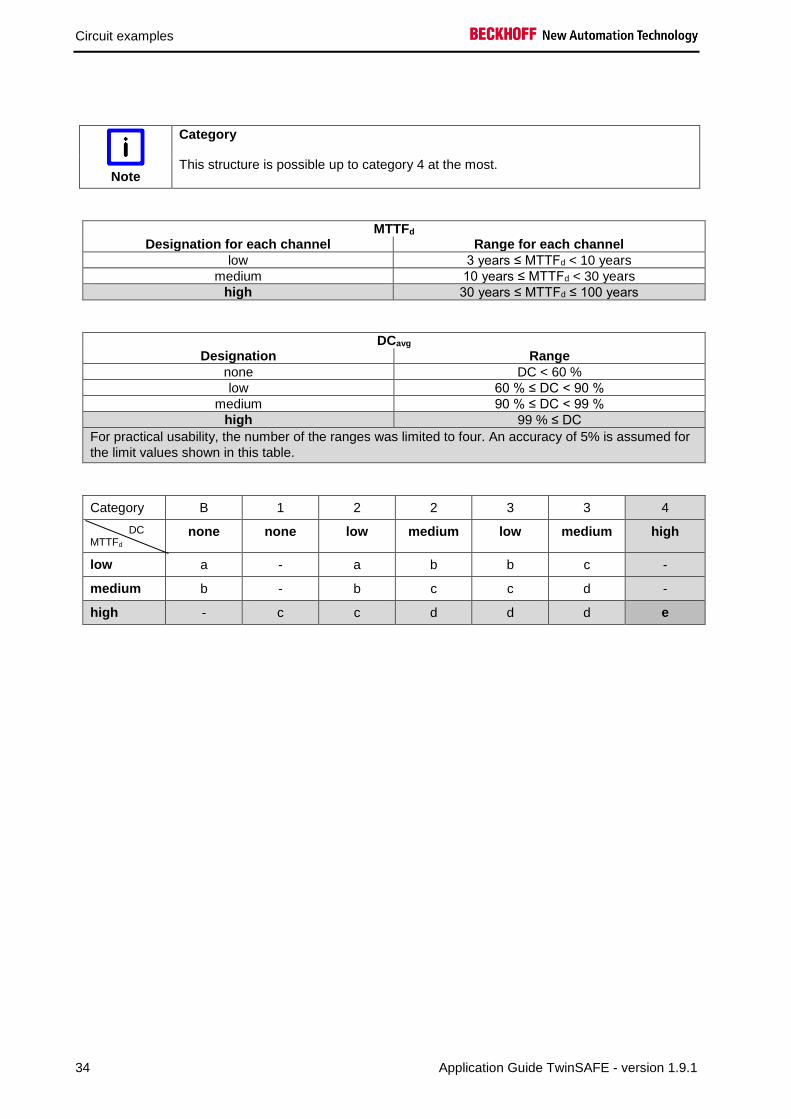
Note
Category
This structure is possible up to category 4 at the most.
MTTFd Designation for each channel Range for each channel
low 3 years ≤ MTTFd < 10 years
medium 10 years ≤ MTTFd < 30 years
high 30 years ≤ MTTFd ≤ 100 years
DCavg Designation Range
none DC < 60 %
low 60 % ≤ DC < 90 %
medium 90 % ≤ DC < 99 %
high 99 % ≤ DC
For practical usability, the number of the ranges was limited to four. An accuracy of 5% is assumed for
the limit values shown in this table.
Category B 1 2 2 3 3 4
DC MTTFd
none none low medium low medium high
low a - a b b c -
medium b - b c c d -
high - c c d d d e

Circuit examples
Application Guide TwinSAFE - version 1.9.1 35
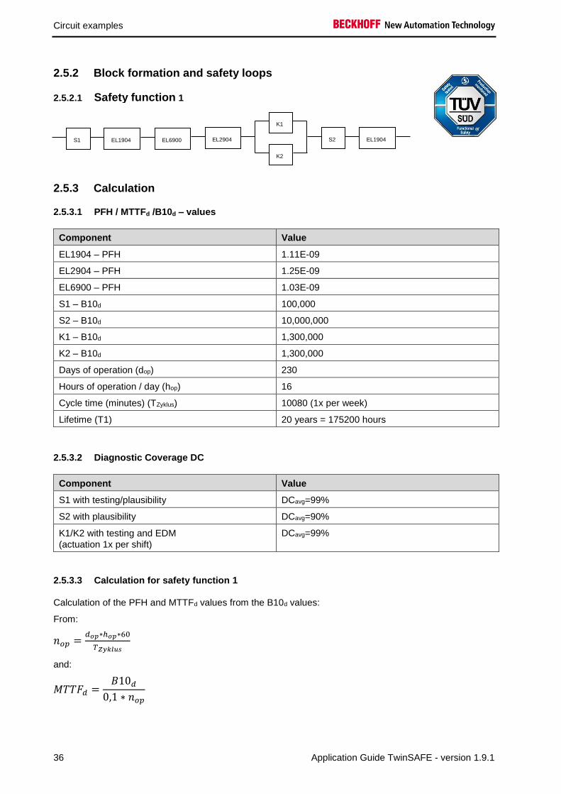
2.5 ESTOP function variant 5 (Category 4, PL e)
The emergency stop button with two normally closed contacts, the restart and the feedback loop are
connected to safe channels of an EL1904 input terminal. The testing of the signals is activated. The two
emergency stop signals are tested for discrepancy. Contactors K1 and K2 are wired to different output
channels. The A2 connections of the two contactors are fed together to ground. The current
measurement of the output channels is deactivated for this circuit. The testing of the outputs is active.
Emergency stop
button
Restart
K1
K2
Logical connection in
the EL6900
K1 K2
S1
S2
2.5.1 Parameters of the safe input and output terminals
EL1904 (applies to all EL1904 used)
Parameter Value
Sensor test channel 1 active Yes
Sensor test channel 2 active Yes
Sensor test channel 3 active Yes
Sensor test channel 4 active Yes
Logic channel 1 and 2 Single Logic
Logic channel 3 and 4 Single Logic
EL2904
Parameter Value
Current measurement active No
Output test pulses active Yes
Circuit examples
36 Application Guide TwinSAFE - version 1.9.1
2.5.2 Block formation and safety loops
2.5.2.1 Safety function 1
2.5.3 Calculation
2.5.3.1 PFH / MTTFd /B10d – values
Component Value
EL1904 – PFH 1.11E-09
EL2904 – PFH 1.25E-09
EL6900 – PFH 1.03E-09
S1 – B10d 100,000
S2 – B10d 10,000,000
K1 – B10d 1,300,000
K2 – B10d 1,300,000
Days of operation (dop) 230
Hours of operation / day (hop) 16
Cycle time (minutes) (TZyklus) 10080 (1x per week)
Lifetime (T1) 20 years = 175200 hours
2.5.3.2 Diagnostic Coverage DC
Component Value
S1 with testing/plausibility DCavg=99%
S2 with plausibility DCavg=90%
K1/K2 with testing and EDM
(actuation 1x per shift)
DCavg=99%
2.5.3.3 Calculation for safety function 1
Calculation of the PFH and MTTFd values from the B10d values:
From:
𝑛𝑜𝑝 =𝑑𝑜𝑝∗ℎ𝑜𝑝∗60
𝑇𝑍𝑦𝑘𝑙𝑢𝑠
and:
𝑀𝑇𝑇𝐹𝑑 =𝐵10𝑑
0,1 ∗ 𝑛𝑜𝑝
S1 EL1904 EL6900 EL2904
K1
K2
S2 EL1904

Circuit examples
Application Guide TwinSAFE - version 1.9.1 37
Inserting the values, this produces:
S1:
𝑛𝑜𝑝 =230∗16∗60
10080= 21,90
𝑀𝑇𝑇𝐹𝑑 =100000
0,1∗21,90= 45662,1y = 399999120h
S2:
𝑛𝑜𝑝 =230∗16∗60
10080= 21,90
𝑀𝑇𝑇𝐹𝑑 =10000000
0,1∗21,90= 4566210,0y = 4E10h
K1/K2:
𝑛𝑜𝑝 =230∗16∗60
10080= 21,90
𝑀𝑇𝑇𝐹𝑑 =1300000
0,1 ∗ 21,90= 593607,3y = 5199997320h
and the assumption that S1, S2, K1 and K2 are each single-channel:
𝑀𝑇𝑇𝐹𝑑 =1
𝜆𝑑
produces for
𝑃𝐹𝐻 =0,1 ∗ 𝑛𝑜𝑝 ∗ (1 − 𝐷𝐶)
𝐵10𝑑=
1 − DC
MTTFd
S1:
𝑃𝐹𝐻 =1 − 0,99
45662,1 ∗ 8760= 2,50E − 11
S2:
𝑃𝐹𝐻 =1 − 0,90
4566210,0 ∗ 8760= 2,50E − 12
K1/K2: actuation 1x per shift
𝑃𝐹𝐻 =1 − 0,99
593607,3 ∗ 8760= 1,92E − 12

Circuit examples
38 Application Guide TwinSAFE - version 1.9.1
The following assumptions must now be made:
Safety switch S1: According to BIA report 2/2008, error exclusion to up 100,000 cycles is possible, provided
the manufacturer has confirmed this. If no confirmation exists, S1 is included in the calculation as follows.
Relays K1 and K2 are both connected to the safety function. The non-functioning of a relay does not lead
to a dangerous situation, but it is discovered by the feedback. Furthermore, the B10d values for K1 and
K2 are identical.
There is a coupling coefficient between the components that are connected via two channels. Examples
are temperature, EMC, voltage peaks or signals between these components. This is assumed to be the
worst-case estimation, where ß =10%. EN 62061 contains a table with which this ß-factor can be
precisely determined. Further, it is assumed that all usual measures have been taken to prevent both
channels failing unsafely at the same time due to an error (e.g. overcurrent through relay contacts,
overtemperature in the control cabinet).
This produces for the calculation of the PFH value for safety function 1:
𝑃𝐹𝐻𝑔𝑒𝑠 = 𝑃𝐹𝐻(𝑆1) + 𝑃𝐹𝐻(𝐸𝐿1904) + 𝑃𝐹𝐻(𝐸𝐿6900) + 𝑃𝐹𝐻(𝐸𝐿2904) + 𝛽 ∗𝑃𝐹𝐻(𝐾1) + 𝑃𝐹𝐻(𝐾2)
2+ (1 − 𝛽)2 ∗ (𝑃𝐹𝐻(𝐾1) ∗ 𝑃𝐹𝐻(𝐾2)) ∗ 𝑇1 + 𝑃𝐹𝐻(𝑆2) + 𝑃𝐹𝐻(𝐸𝐿1904)
Since the portion (1 − 𝛽)2 ∗ (𝑃𝐹𝐻(𝐾1) ∗ 𝑃𝐹𝐻(𝐾2)) ∗ 𝑇1 is smaller than the rest by the power of ten, it is
neglected in this and all further calculations for the purpose of simplification.
to:
𝑃𝐹𝐻𝑔𝑒𝑠 = 2,5𝐸 − 11 + 1,11𝐸 − 09 + 1,03𝐸 − 09 + 1,25𝐸 − 09 + 10% ∗1,92𝐸 − 12 + 1,92𝐸 − 12
2+ 2,5𝐸 − 12 + 1,11𝐸 − 09 = 4,53𝐸 − 09
in the case of actuation 1x per shift
The MTTFd value for safety function 1 (based on the same assumption) is calculated with:
1
𝑀𝑇𝑇𝐹𝑑 𝑔𝑒𝑠
= ∑1
𝑀𝑇𝑇𝐹𝑑 𝑛
𝑛
𝑖=1
as:
1
𝑀𝑇𝑇𝐹𝑑 𝑔𝑒𝑠
=1
𝑀𝑇𝑇𝐹𝑑 (𝑆1)+
1
𝑀𝑇𝑇𝐹𝑑(𝐸𝐿1904)+
1
𝑀𝑇𝑇𝐹𝑑 (𝐸𝐿6900)+
1
𝑀𝑇𝑇𝐹𝑑(𝐸𝐿2904)+
1
𝑀𝑇𝑇𝐹𝑑 (𝐾1)
+1
𝑀𝑇𝑇𝐹𝑑 (𝑆2)+
1
𝑀𝑇𝑇𝐹𝑑(𝐸𝐿1904)
with:
𝑀𝑇𝑇𝐹𝑑(S1) =𝐵10𝑑(𝑆1)
0,1 ∗ 𝑛𝑜𝑝
𝑀𝑇𝑇𝐹𝑑(S2) =𝐵10𝑑(𝑆2)
0,1 ∗ 𝑛𝑜𝑝
𝑀𝑇𝑇𝐹𝑑(K1) =𝐵10𝑑(𝐾1)
0,1 ∗ 𝑛𝑜𝑝

Circuit examples
Application Guide TwinSAFE - version 1.9.1 39
If only PFH values are available for EL1904, EL2904 and EL6900, the following estimation applies:
𝑀𝑇𝑇𝐹𝑑(ELxxxx) =(1 − 𝐷𝐶(𝐸𝐿𝑥𝑥𝑥))
𝑃𝐹𝐻(𝐸𝐿𝑥𝑥𝑥)
Hence:
𝑀𝑇𝑇𝐹𝑑(EL1904) =(1 − 𝐷𝐶(𝐸𝐿1904))
𝑃𝐹𝐻(𝐸𝐿1904)=
(1 − 0,99)
1,11E − 09 1
h∗ 8760h
y
=0,01
9,72E − 061
y
= 1028,8y
𝑀𝑇𝑇𝐹𝑑(EL6900) =(1 − 𝐷𝐶(𝐸𝐿6900))
𝑃𝐹𝐻(𝐸𝐿6900) =
(1 − 0,99)
1,03E − 091
h∗ 8760h
y
=0,01
9,02E − 061
y
= 1108,6y
𝑀𝑇𝑇𝐹𝑑(EL2904) =(1 − 𝐷𝐶(𝐸𝐿2904))
𝑃𝐹𝐻(𝐸𝐿2904) =
(1 − 0,99)
1,25E − 091
h∗ 8760h
y
=0,01
1,1E − 051
y
= 913,2y
𝑀𝑇𝑇𝐹𝐷𝑔𝑒𝑠 =1
1
45662,1𝑦+
1
1028,8𝑦+
1
1108,6𝑦+
1
913,2𝑦+
1
593607,3𝑦+
1
4566210,0𝑦+
1
1028,8𝑦
= 252,1𝑦
𝐷𝐶𝑎𝑣𝑔 =
99%
45662,1+
99%
1028,8+
99%
1108,6+
99%
913,2+
90%
593607,3+
90%
593607,3+
90%
4566210,0+
99%
1028,81
45662,1+
1
1028,8+
1
1108,6+
1
913,2+
1
593607,3+
1
593607,3+
1
4566210,0+
1
1028,8
= 98,99%
or:
𝐷𝐶𝑎𝑣𝑔 =
99%
45662,1+
99%
1028,8+
99%
1108,6+
99%
913,2+
99%
593607,3+
99%
593607,3+
90%
4566210,0+
99%
1028,81
45662,1+
1
1028,8+
1
1108,6+
1
913,2+
1
593607,3+
1
593607,3+
1
4566210,0+
1
1028,8
= 99,0%

Circuit examples
40 Application Guide TwinSAFE - version 1.9.1
Note
Category
This structure is possible up to category 4 at the most.
MTTFd Designation for each channel Range for each channel
low 3 years ≤ MTTFd < 10 years
medium 10 years ≤ MTTFd < 30 years
high 30 years ≤ MTTFd ≤ 100 years
DCavg Designation Range
none DC < 60 %
low 60 % ≤ DC < 90 %
medium 90 % ≤ DC < 99 %
high 99 % ≤ DC
For practical usability, the number of the ranges was limited to four. An accuracy of 5% is assumed for
the limit values shown in this table.
Category B 1 2 2 3 3 4
DC MTTFd
none none low medium low medium high
low a - a b b c -
medium b - b c c d -
high - c c d d d e

Circuit examples
Application Guide TwinSAFE - version 1.9.1 41
2.6 ESTOP function variant 6 (Category 3, PL d)
The emergency stop button with two normally closed contacts, the restart and the feedback loop are
connected to safe channels of an EL1904 input terminal. The testing of the signals is activated. The two
emergency stop signals are tested for discrepancy. Contactors K1 and K2 are wired to different output
channels. The A2 connections of the two contactors are fed together to ground. The current
measurement of the output channels is deactivated for this circuit. The testing of the outputs is not active.
Emergency stop
button
Restart
K1
K2
Logical connection in
the EL6900
K1 K2
S1
S2
Note
Category
This structure is possible only up to category 3 at the most on account of a possible sleeping error.
Since the EL2904 terminal has only SIL2 in this application, the entire chain has only
SIL2!
2.6.1 Parameters of the safe input and output terminals (SIL 2)
EL1904 (applies to all EL1904 used)
Parameter Value
Sensor test channel 1 active Yes
Sensor test channel 2 active Yes
Sensor test channel 3 active Yes
Sensor test channel 4 active Yes
Logic channel 1 and 2 Single Logic
Logic channel 3 and 4 Single Logic

Circuit examples
42 Application Guide TwinSAFE - version 1.9.1
EL2904
Parameter Value
Current measurement active No
Output test pulses active No
2.6.2 Block formation and safety loops
2.6.2.1 Safety function 1
2.6.3 Calculation
2.6.3.1 PFH / MTTFd /B10d – values
Component Value
EL1904 – PFH 1.11E-09
EL2904 – PFH 1.25E-09
EL6900 – PFH 1.03E-09
S1 – B10d 100,000
S2 – B10d 10,000,000
K1 – B10d 1,300,000
K2 – B10d 1,300,000
Days of operation (dop) 230
Hours of operation / day (hop) 16
Cycle time (minutes) (TZyklus) 10080 (1x per week)
Lifetime (T1) 20 years = 175200 hours
2.6.3.2 Diagnostic Coverage DC
Component Value
S1 with testing/plausibility DCavg=99%
S2 with plausibility DCavg=90%
K1/K2 without testing and with EDM via a safe
input
DCavg=90%
S1 EL1904 EL6900 EL2904
K1
K2
S2 EL1904

Circuit examples
Application Guide TwinSAFE - version 1.9.1 43
2.6.3.3 Calculation for safety function 1
Calculation of the PFH and MTTFd values from the B10d values:
From:
𝑛𝑜𝑝 =𝑑𝑜𝑝∗ℎ𝑜𝑝∗60
𝑇𝑍𝑦𝑘𝑙𝑢𝑠
and:
𝑀𝑇𝑇𝐹𝑑 =𝐵10𝑑
0,1 ∗ 𝑛𝑜𝑝
Inserting the values, this produces:
S1:
𝑛𝑜𝑝 =230∗16∗60
10080= 21,90
𝑀𝑇𝑇𝐹𝑑 =100000
0,1∗21,90= 45662,1y = 399999120h
S2:
𝑛𝑜𝑝 =230∗16∗60
10080= 21,90
𝑀𝑇𝑇𝐹𝑑 =10000000
0,1∗21,90= 4566210,0y = 4E10h
K1/K2:
𝑛𝑜𝑝 =230∗16∗60
10080= 21,90
𝑀𝑇𝑇𝐹𝑑 =1300000
0,1 ∗ 21,90= 593607,3y = 5199997320h
and the assumption that S1, S2, K1 and K2 are each single-channel:
𝑀𝑇𝑇𝐹𝑑 =1
𝜆𝑑
produces for
𝑃𝐹𝐻 =0,1 ∗ 𝑛𝑜𝑝 ∗ (1 − 𝐷𝐶)
𝐵10𝑑=
1 − DC
MTTFd
S1:
𝑃𝐹𝐻 =1 − 0,99
45662,1 ∗ 8760= 2,50E − 11
S2:
𝑃𝐹𝐻 =1 − 0,90
4566210,0 ∗ 8760= 2,50E − 12
K1/K2: actuation 1x per shift
𝑃𝐹𝐻 =1 − 0,99
593607,3 ∗ 8760= 1,92E − 12

Circuit examples
44 Application Guide TwinSAFE - version 1.9.1
The following assumptions must now be made:
Safety switch S1: According to BIA report 2/2008, error exclusion to up 100,000 cycles is possible, provided
the manufacturer has confirmed this. If no confirmation exists, S1 is included in the calculation as follows.
Relays K1 and K2 are both connected to the safety function. The non-functioning of a relay does not lead
to a dangerous situation, but it is discovered by the feedback. Furthermore, the B10d values for K1 and
K2 are identical.
There is a coupling coefficient between the components that are connected via two channels. Examples
are temperature, EMC, voltage peaks or signals between these components. This is assumed to be the
worst-case estimation, where ß =10%. EN 62061 contains a table with which this ß-factor can be
precisely determined. Further, it is assumed that all usual measures have been taken to prevent both
channels failing unsafely at the same time due to an error (e.g. overcurrent through relay contacts,
overtemperature in the control cabinet).
This produces for the calculation of the PFH value for safety function 1:
𝑃𝐹𝐻𝑔𝑒𝑠 = 𝑃𝐹𝐻(𝑆1) + 𝑃𝐹𝐻(𝐸𝐿1904) + 𝑃𝐹𝐻(𝐸𝐿6900) + 𝑃𝐹𝐻(𝐸𝐿2904) + 𝛽 ∗𝑃𝐹𝐻(𝐾1) + 𝑃𝐹𝐻(𝐾2)
2+ (1 − 𝛽)2 ∗ (𝑃𝐹𝐻(𝐾1) ∗ 𝑃𝐹𝐻(𝐾2)) ∗ 𝑇1 + 𝑃𝐹𝐻(𝑆2) + 𝑃𝐹𝐻(𝐸𝐿1904)
Since the portion (1 − 𝛽)2 ∗ (𝑃𝐹𝐻(𝐾1) ∗ 𝑃𝐹𝐻(𝐾2)) ∗ 𝑇1 is smaller than the rest by the power of ten, it is
neglected in this and all further calculations for the purpose of simplification.
to:
𝑃𝐹𝐻𝑔𝑒𝑠 = 2,5𝐸 − 11 + 1,11𝐸 − 09 + 1,03𝐸 − 09 + 1,25𝐸 − 09 + 10% ∗1,92𝐸 − 12 + 1,92𝐸 − 12
2+ 2,5𝐸 − 12 + 1,11𝐸 − 09 = 4,53𝐸 − 09
in the case of actuation 1x per shift
The MTTFd value for safety function 1 (based on the same assumption) is calculated with:
1
𝑀𝑇𝑇𝐹𝑑 𝑔𝑒𝑠
= ∑1
𝑀𝑇𝑇𝐹𝑑 𝑛
𝑛
𝑖=1
as:
1
𝑀𝑇𝑇𝐹𝑑 𝑔𝑒𝑠
=1
𝑀𝑇𝑇𝐹𝑑 (𝑆1)+
1
𝑀𝑇𝑇𝐹𝑑(𝐸𝐿1904)+
1
𝑀𝑇𝑇𝐹𝑑 (𝐸𝐿6900)+
1
𝑀𝑇𝑇𝐹𝑑(𝐸𝐿2904)+
1
𝑀𝑇𝑇𝐹𝑑 (𝐾1)
+1
𝑀𝑇𝑇𝐹𝑑 (𝑆2)+
1
𝑀𝑇𝑇𝐹𝑑(𝐸𝐿1904)
with:
𝑀𝑇𝑇𝐹𝑑(S1) =𝐵10𝑑(𝑆1)
0,1 ∗ 𝑛𝑜𝑝
𝑀𝑇𝑇𝐹𝑑(S2) =𝐵10𝑑(𝑆2)
0,1 ∗ 𝑛𝑜𝑝
𝑀𝑇𝑇𝐹𝑑(K1) =𝐵10𝑑(𝐾1)
0,1 ∗ 𝑛𝑜𝑝

Circuit examples
Application Guide TwinSAFE - version 1.9.1 45
If only PFH values are available for EL1904, EL2904 and EL6900, the following estimation applies:
𝑀𝑇𝑇𝐹𝑑(ELxxxx) =(1 − 𝐷𝐶(𝐸𝐿𝑥𝑥𝑥))
𝑃𝐹𝐻(𝐸𝐿𝑥𝑥𝑥)
Hence:
𝑀𝑇𝑇𝐹𝑑(EL1904) =(1 − 𝐷𝐶(𝐸𝐿1904))
𝑃𝐹𝐻(𝐸𝐿1904)=
(1 − 0,99)
1,11E − 09 1
h∗ 8760h
y
=0,01
9,72E − 061
y
= 1028,8y
𝑀𝑇𝑇𝐹𝑑(EL6900) =(1 − 𝐷𝐶(𝐸𝐿6900))
𝑃𝐹𝐻(𝐸𝐿6900) =
(1 − 0,99)
1,03E − 091
h∗ 8760h
y
=0,01
9,02E − 061
y
= 1108,6y
𝑀𝑇𝑇𝐹𝑑(EL2904) =(1 − 𝐷𝐶(𝐸𝐿2904))
𝑃𝐹𝐻(𝐸𝐿2904) =
(1 − 0,99)
1,25E − 091
h∗ 8760h
y
=0,01
1,1E − 051
y
= 913,2y
𝑀𝑇𝑇𝐹𝐷𝑔𝑒𝑠 =1
1
45662,1𝑦+
1
1028,8𝑦+
1
1108,6𝑦+
1
913,2𝑦+
1
593607,3𝑦+
1
4566210,0𝑦+
1
1028,8𝑦
= 252,1𝑦
𝐷𝐶𝑎𝑣𝑔 =
99%
45662,1+
99%
1028,8+
99%
1108,6+
99%
913,2+
90%
593607,3+
90%
593607,3+
90%
4566210,0+
99%
1028,81
45662,1+
1
1028,8+
1
1108,6+
1
913,2+
1
593607,3+
1
593607,3+
1
4566210,0+
1
1028,8
= 98,99%

Circuit examples
46 Application Guide TwinSAFE - version 1.9.1
Note
Category
This structure is possible only up to category 3 at the most on account of a possible sleeping error.
Since the EL2904 terminal has only SIL2 in this application, the entire chain has only
SIL2!
MTTFd Designation for each channel Range for each channel
low 3 years ≤ MTTFd < 10 years
medium 10 years ≤ MTTFd < 30 years
high 30 years ≤ MTTFd ≤ 100 years
DCavg Designation Range
none DC < 60 %
low 60 % ≤ DC < 90 %
medium 90 % ≤ DC < 99 %
high 99 % ≤ DC
Category B 1 2 2 3 3 4
DC MTTFd
none none low medium low medium high
low a - a b b c -
medium b - b c c d -
high - c c d d d e

Circuit examples
Application Guide TwinSAFE - version 1.9.1 47
2.7 ESTOP function variant 7 (Category 4, PL e)
The emergency stop button with two normally closed contacts, the restart and the feedback loop are
connected to safe channels of an EL1904 input terminal. The testing of the emergency stop button is
deactivated on both channels. The sensor test is activated for the restart button and the feedback loop.
The two emergency stop signals are tested for discrepancy. The contactors K1 and K2 are connected in
parallel to the safe output. Current measurement and testing of the output are active for this circuit.
Emergency stop
button
Restart
K1
K2
Logical connection in
the EL6900
K1 K2
S1
S2
2.7.1 Parameters of the safe input and output terminals
1. EL1904
Parameter Value
Sensor test channel 1 active Yes
Sensor test channel 2 active not used
Sensor test channel 3 active No
Sensor test channel 4 active No
Logic channel 1 and 2 Single Logic
Logic channel 3 and 4 Single Logic
2. EL1904
Parameter Value
Sensor test channel 1 active not used
Sensor test channel 2 active not used
Sensor test channel 3 active Yes
Sensor test channel 4 active not used
Logic channel 1 and 2 Single Logic
Logic channel 3 and 4 Single Logic

Circuit examples
48 Application Guide TwinSAFE - version 1.9.1
EL2904
Parameter Value
Current measurement active Yes
Output test pulses active Yes
2.7.2 Block formation and safety loops
2.7.2.1 Safety function 1
2.7.3 Calculation
2.7.3.1 PFH / MTTFd /B10d – values
Component Value
EL1904 – PFH 1.11E-09
EL2904 – PFH 1.25E-09
EL6900 – PFH 1.03E-09
S1 – B10d 100,000
S2 – B10d 10,000,000
K1 – B10d 1,300,000
K2 – B10d 1,300,000
Days of operation (dop) 230
Hours of operation / day (hop) 16
Cycle time (minutes) (TZyklus) 10080 (1x per week)
Lifetime (T1) 20 years = 175200 hours
2.7.3.2 Diagnostic Coverage DC
Component Value
S1 with plausibility DCavg=90%
S2 with testing DCavg=90%
K1/K2 with testing and EDM
(actuation 1x per shift)
DCavg=99%
S1 EL1904 EL6900 EL2904
K1
K2
S2 EL1904

Circuit examples
Application Guide TwinSAFE - version 1.9.1 49
2.7.3.3 Calculation for safety function 1
Calculation of the PFH and MTTFd values from the B10d values:
From:
𝑛𝑜𝑝 =𝑑𝑜𝑝∗ℎ𝑜𝑝∗60
𝑇𝑍𝑦𝑘𝑙𝑢𝑠
and:
𝑀𝑇𝑇𝐹𝑑 =𝐵10𝑑
0,1 ∗ 𝑛𝑜𝑝
Inserting the values, this produces:
S1:
𝑛𝑜𝑝 =230∗16∗60
10080= 21,90
𝑀𝑇𝑇𝐹𝑑 =100000
0,1∗21,90= 45662,1y = 399999120h
S2:
𝑛𝑜𝑝 =230∗16∗60
10080= 21,90
𝑀𝑇𝑇𝐹𝑑 =10000000
0,1∗21,90= 4566210,0y = 4E10h
K1/K2:
𝑛𝑜𝑝 =230∗16∗60
10080= 21,90
𝑀𝑇𝑇𝐹𝑑 =1300000
0,1 ∗ 21,90= 593607,3y = 5199997320h
and the assumption that S1, S2, K1 and K2 are each single-channel:
𝑀𝑇𝑇𝐹𝑑 =1
𝜆𝑑
produces for
𝑃𝐹𝐻 =0,1 ∗ 𝑛𝑜𝑝 ∗ (1 − 𝐷𝐶)
𝐵10𝑑=
1 − DC
MTTFd
S1:
𝑃𝐹𝐻 =1 − 0,90
45662,1 ∗ 8760= 2,50E − 10
S2:
𝑃𝐹𝐻 =1 − 0,90
4566210,0 ∗ 8760= 2,50E − 12
K1/K2: actuation 1x per shift and direct feedback
𝑃𝐹𝐻 =1 − 0,99
593607,3 ∗ 8760= 1,92E − 12
Circuit examples
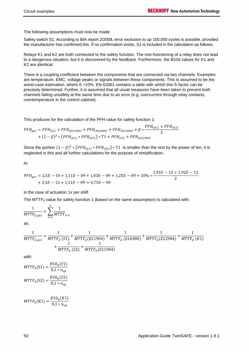
50 Application Guide TwinSAFE - version 1.9.1
The following assumptions must now be made:
Safety switch S1: According to BIA report 2/2008, error exclusion to up 100,000 cycles is possible, provided
the manufacturer has confirmed this. If no confirmation exists, S1 is included in the calculation as follows.
Relays K1 and K2 are both connected to the safety function. The non-functioning of a relay does not lead
to a dangerous situation, but it is discovered by the feedback. Furthermore, the B10d values for K1 and
K2 are identical.
There is a coupling coefficient between the components that are connected via two channels. Examples
are temperature, EMC, voltage peaks or signals between these components. This is assumed to be the
worst-case estimation, where ß =10%. EN 62061 contains a table with which this ß-factor can be
precisely determined. Further, it is assumed that all usual measures have been taken to prevent both
channels failing unsafely at the same time due to an error (e.g. overcurrent through relay contacts,
overtemperature in the control cabinet).
This produces for the calculation of the PFH value for safety function 1:
𝑃𝐹𝐻𝑔𝑒𝑠 = 𝑃𝐹𝐻(𝑆1) + 𝑃𝐹𝐻(𝐸𝐿1904) + 𝑃𝐹𝐻(𝐸𝐿6900) + 𝑃𝐹𝐻(𝐸𝐿2904) + 𝛽 ∗𝑃𝐹𝐻(𝐾1) + 𝑃𝐹𝐻(𝐾2)
2+ (1 − 𝛽)2 ∗ (𝑃𝐹𝐻(𝐾1) ∗ 𝑃𝐹𝐻(𝐾2)) ∗ 𝑇1 + 𝑃𝐹𝐻(𝑆2) + 𝑃𝐹𝐻(𝐸𝐿1904)
Since the portion (1 − 𝛽)2 ∗ (𝑃𝐹𝐻(𝐾1) ∗ 𝑃𝐹𝐻(𝐾2)) ∗ 𝑇1 is smaller than the rest by the power of ten, it is
neglected in this and all further calculations for the purpose of simplification.
to:
𝑃𝐹𝐻𝑔𝑒𝑠 = 2,5𝐸 − 10 + 1,11𝐸 − 09 + 1,03𝐸 − 09 + 1,25𝐸 − 09 + 10% ∗1,92𝐸 − 12 + 1,92𝐸 − 12
2+ 2,5𝐸 − 12 + 1,11𝐸 − 09 = 4,75𝐸 − 09
in the case of actuation 1x per shift
The MTTFd value for safety function 1 (based on the same assumption) is calculated with:
1
𝑀𝑇𝑇𝐹𝑑 𝑔𝑒𝑠
= ∑1
𝑀𝑇𝑇𝐹𝑑 𝑛
𝑛
𝑖=1
as:
1
𝑀𝑇𝑇𝐹𝑑 𝑔𝑒𝑠
=1
𝑀𝑇𝑇𝐹𝑑 (𝑆1)+
1
𝑀𝑇𝑇𝐹𝑑(𝐸𝐿1904)+
1
𝑀𝑇𝑇𝐹𝑑 (𝐸𝐿6900)+
1
𝑀𝑇𝑇𝐹𝑑(𝐸𝐿2904)+
1
𝑀𝑇𝑇𝐹𝑑 (𝐾1)
+1
𝑀𝑇𝑇𝐹𝑑 (𝑆2)+
1
𝑀𝑇𝑇𝐹𝑑(𝐸𝐿1904)
with:
𝑀𝑇𝑇𝐹𝑑(S1) =𝐵10𝑑(𝑆1)
0,1 ∗ 𝑛𝑜𝑝
𝑀𝑇𝑇𝐹𝑑(S2) =𝐵10𝑑(𝑆2)
0,1 ∗ 𝑛𝑜𝑝
𝑀𝑇𝑇𝐹𝑑(K1) =𝐵10𝑑(𝐾1)
0,1 ∗ 𝑛𝑜𝑝

Circuit examples
Application Guide TwinSAFE - version 1.9.1 51
If only PFH values are available for EL1904, EL2904 and EL6900, the following estimation applies:
𝑀𝑇𝑇𝐹𝑑(ELxxxx) =(1 − 𝐷𝐶(𝐸𝐿𝑥𝑥𝑥))
𝑃𝐹𝐻(𝐸𝐿𝑥𝑥𝑥)
Hence:
𝑀𝑇𝑇𝐹𝑑(EL1904) =(1 − 𝐷𝐶(𝐸𝐿1904))
𝑃𝐹𝐻(𝐸𝐿1904)=
(1 − 0,99)
1,11E − 09 1
h∗ 8760h
y
=0,01
9,72E − 061
y
= 1028,8y
𝑀𝑇𝑇𝐹𝑑(EL6900) =(1 − 𝐷𝐶(𝐸𝐿6900))
𝑃𝐹𝐻(𝐸𝐿6900) =
(1 − 0,99)
1,03E − 091
h∗ 8760h
y
=0,01
9,02E − 061
y
= 1108,6y
𝑀𝑇𝑇𝐹𝑑(EL2904) =(1 − 𝐷𝐶(𝐸𝐿2904))
𝑃𝐹𝐻(𝐸𝐿2904) =
(1 − 0,99)
1,25E − 091
h∗ 8760h
y
=0,01
1,1E − 051
y
= 913,2y
𝑀𝑇𝑇𝐹𝐷𝑔𝑒𝑠 =1
1
45662,1𝑦+
1
1028,8𝑦+
1
1108,6𝑦+
1
913,2𝑦+
1
593607,3𝑦+
1
4566210,0𝑦+
1
1028,8𝑦
= 252,1𝑦
𝐷𝐶𝑎𝑣𝑔 =
90%
45662,1+
99%
1028,8+
99%
1108,6+
99%
913,2+
90%
593607,3+
90%
593607,3+
90%
4566210,0+
99%
1028,81
45662,1+
1
1028,8+
1
1108,6+
1
913,2+
1
593607,3+
1
593607,3+
1
4566210,0+
1
1028,8
= 98,94%
or:
𝐷𝐶𝑎𝑣𝑔 =
90%
45662,1+
99%
1028,8+
99%
1108,6+
99%
913,2+
99%
593607,3+
99%
593607,3+
90%
4566210,0+
99%
1028,81
45662,1+
1
1028,8+
1
1108,6+
1
913,2+
1
593607,3+
1
593607,3+
1
4566210,0+
1
1028,8
= 98,95%

Circuit examples
52 Application Guide TwinSAFE - version 1.9.1
Note
Category
This structure is possible up to category 4 at the most.
MTTFd Designation for each channel Range for each channel
low 3 years ≤ MTTFd < 10 years
medium 10 years ≤ MTTFd < 30 years
high 30 years ≤ MTTFd ≤ 100 years
DCavg Designation Range
none DC < 60 %
low 60 % ≤ DC < 90 %
medium 90 % ≤ DC < 99 %
high 99 % ≤ DC
For practical usability, the number of the ranges was limited to four. An accuracy of 5% is assumed for
the limit values shown in this table.
Category B 1 2 2 3 3 4
DC MTTFd
none none low medium low medium high
low a - a b b c -
medium b - b c c d -
high - c c d d d e

Circuit examples
Application Guide TwinSAFE - version 1.9.1 53
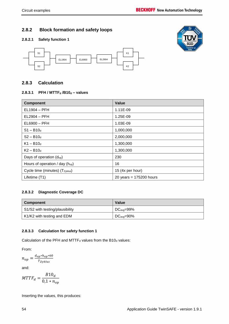
2.8 Protective door function variant 1 (Category 3, PL d)
The protective door uses a combination of normally closed and normally open contacts on the safe inputs
of an EL1904. The testing of the inputs is active and the signals are tested for discrepancy (200 ms). The
feedback loop is read in via a standard input and transferred to TwinSAFE via the standard PLC. The
contactors K1 and K2 are connected in parallel to the safe output. Current measurement and testing of
the output are active for this circuit.
K1
K2
CLOSED
OPEN
Logical connection in
the EL6900
K1 K2S1
S2
2.8.1 Parameters of the safe input and output terminals
EL1904 (applies to all EL1904 used)
Parameter Value
Sensor test channel 1 active Yes
Sensor test channel 2 active Yes
Sensor test channel 3 active Yes
Sensor test channel 4 active Yes
Logic channel 1 and 2 Single Logic
Logic channel 3 and 4 Single Logic
EL2904
Parameter Value
Current measurement active Yes
Output test pulses active Yes
Circuit examples
54 Application Guide TwinSAFE - version 1.9.1
2.8.2 Block formation and safety loops
2.8.2.1 Safety function 1
2.8.3 Calculation
2.8.3.1 PFH / MTTFd /B10d – values
Component Value
EL1904 – PFH 1.11E-09
EL2904 – PFH 1.25E-09
EL6900 – PFH 1.03E-09
S1 – B10d 1,000,000
S2 – B10d 2,000,000
K1 – B10d 1,300,000
K2 – B10d 1,300,000
Days of operation (dop) 230
Hours of operation / day (hop) 16
Cycle time (minutes) (TZyklus) 15 (4x per hour)
Lifetime (T1) 20 years = 175200 hours
2.8.3.2 Diagnostic Coverage DC
Component Value
S1/S2 with testing/plausibility DCavg=99%
K1/K2 with testing and EDM DCavg=90%
2.8.3.3 Calculation for safety function 1
Calculation of the PFH and MTTFd values from the B10d values:
From:
𝑛𝑜𝑝 =𝑑𝑜𝑝∗ℎ𝑜𝑝∗60
𝑇𝑍𝑦𝑘𝑙𝑢𝑠
and:
𝑀𝑇𝑇𝐹𝑑 =𝐵10𝑑
0,1 ∗ 𝑛𝑜𝑝
Inserting the values, this produces:
K1
K2
EL1904 EL6900 EL2904
S1
S2

Circuit examples
Application Guide TwinSAFE - version 1.9.1 55
S1:
𝑛𝑜𝑝 =230∗16∗60
15= 14720
𝑀𝑇𝑇𝐹𝑑 =1000000
0,1∗14720= 679,3y = 5951087h
S2:
𝑛𝑜𝑝 =230∗16∗60
15= 14720
𝑀𝑇𝑇𝐹𝑑 =2000000
0,1∗14720= 1358,7y = 11902174h
K1/K2:
𝑛𝑜𝑝 =230∗16∗60
15= 14720
𝑀𝑇𝑇𝐹𝑑 =1300000
0,1 ∗ 14720= 883,2y = 7736413h
and the assumption that S1, S2, K1 and K2 are each single-channel:
𝑀𝑇𝑇𝐹𝑑 =1
𝜆𝑑
produces for
𝑃𝐹𝐻 =0,1 ∗ 𝑛𝑜𝑝 ∗ (1 − 𝐷𝐶)
𝐵10𝑑=
1 − DC
MTTFd
S1:
𝑃𝐹𝐻 =1 − 0,99
679,3 ∗ 8760= 1,68E − 9
S2:
𝑃𝐹𝐻 =1 − 0,99
1358,7 ∗ 8760= 8,4E − 10
K1/K2:
𝑃𝐹𝐻 =1 − 0,90
883,2 ∗ 8760= 1,29E − 8
The following assumptions must now be made:
The door switches S1/S2 are always actuated in opposite directions. Since the switches have different
values, but the complete protective door switch consists of a combination of normally closed and normally
open contacts and both switches must function, the poorer of the two values (S1) can be taken for the
combination!
Relays K1 and K2 are both connected to the safety function. The non-functioning of a relay does not lead
to a dangerous situation, but it is discovered by the feedback. Furthermore, the B10d values for K1 and
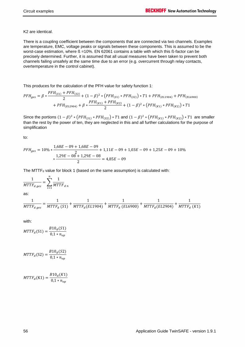
Circuit examples
56 Application Guide TwinSAFE - version 1.9.1
K2 are identical.
There is a coupling coefficient between the components that are connected via two channels. Examples
are temperature, EMC, voltage peaks or signals between these components. This is assumed to be the
worst-case estimation, where ß =10%. EN 62061 contains a table with which this ß-factor can be
precisely determined. Further, it is assumed that all usual measures have been taken to prevent both
channels failing unsafely at the same time due to an error (e.g. overcurrent through relay contacts,
overtemperature in the control cabinet).
This produces for the calculation of the PFH value for safety function 1:
𝑃𝐹𝐻𝑔𝑒𝑠 = 𝛽 ∗𝑃𝐹𝐻(𝑆1) + 𝑃𝐹𝐻(𝑆2)
2+ (1 − 𝛽)2 ∗ (𝑃𝐹𝐻(𝑆1) ∗ 𝑃𝐹𝐻(𝑆2)) ∗ 𝑇1 + 𝑃𝐹𝐻(𝐸𝐿1904) + 𝑃𝐹𝐻(𝐸𝐿6900)
+ 𝑃𝐹𝐻(𝐸𝐿2904) + 𝛽 ∗𝑃𝐹𝐻(𝐾1) + 𝑃𝐹𝐻(𝐾2)
2+ (1 − 𝛽)2 ∗ (𝑃𝐹𝐻(𝐾1) ∗ 𝑃𝐹𝐻(𝐾2)) ∗ 𝑇1
Since the portions (1 − 𝛽)2 ∗ (𝑃𝐹𝐻(𝑆1) ∗ 𝑃𝐹𝐻(𝑆2)) ∗ 𝑇1 and (1 − 𝛽)2 ∗ (𝑃𝐹𝐻(𝐾1) ∗ 𝑃𝐹𝐻(𝐾2)) ∗ 𝑇1 are smaller
than the rest by the power of ten, they are neglected in this and all further calculations for the purpose of
simplification
to:
𝑃𝐹𝐻𝑔𝑒𝑠 = 10% ∗1,68𝐸 − 09 + 1,68𝐸 − 09
2+ 1,11𝐸 − 09 + 1,03𝐸 − 09 + 1,25𝐸 − 09 + 10%
∗1,29𝐸 − 08 + 1,29𝐸 − 08
2= 4,85𝐸 − 09
The MTTFd value for block 1 (based on the same assumption) is calculated with:
1
𝑀𝑇𝑇𝐹𝑑 𝑔𝑒𝑠
= ∑1
𝑀𝑇𝑇𝐹𝑑 𝑛
𝑛
𝑖=1
as:
1
𝑀𝑇𝑇𝐹𝑑 𝑔𝑒𝑠
=1
𝑀𝑇𝑇𝐹𝑑 (𝑆1)+
1
𝑀𝑇𝑇𝐹𝑑(𝐸𝐿1904)+
1
𝑀𝑇𝑇𝐹𝑑 (𝐸𝐿6900)+
1
𝑀𝑇𝑇𝐹𝑑(𝐸𝐿2904)+
1
𝑀𝑇𝑇𝐹𝑑 (𝐾1)
with:
𝑀𝑇𝑇𝐹𝑑(S1) =𝐵10𝑑(𝑆1)
0,1 ∗ 𝑛𝑜𝑝
𝑀𝑇𝑇𝐹𝑑(S2) =𝐵10𝑑(𝑆2)
0,1 ∗ 𝑛𝑜𝑝
𝑀𝑇𝑇𝐹𝑑(K1) =𝐵10𝑑(𝐾1)
0,1 ∗ 𝑛𝑜𝑝

Circuit examples
Application Guide TwinSAFE - version 1.9.1 57
If only PFH values are available for EL1904, EL2904 and EL6900, the following estimation applies:
𝑀𝑇𝑇𝐹𝑑(ELxxxx) =(1 − 𝐷𝐶(𝐸𝐿𝑥𝑥𝑥))
𝑃𝐹𝐻(𝐸𝐿𝑥𝑥𝑥)
Hence:
𝑀𝑇𝑇𝐹𝑑(EL1904) =(1 − 𝐷𝐶(𝐸𝐿1904))
𝑃𝐹𝐻(𝐸𝐿1904)=
(1 − 0,99)
1,11E − 09 1
h∗ 8760h
y
=0,01
9,72E − 061
y
= 1028,8y
𝑀𝑇𝑇𝐹𝑑(EL6900) =(1 − 𝐷𝐶(𝐸𝐿6900))
𝑃𝐹𝐻(𝐸𝐿6900) =
(1 − 0,99)
1,03E − 091
h∗ 8760h
y
=0,01
9,02E − 061
y
= 1108,6y
𝑀𝑇𝑇𝐹𝑑(EL2904) =(1 − 𝐷𝐶(𝐸𝐿2904))
𝑃𝐹𝐻(𝐸𝐿2904) =
(1 − 0,99)
1,25E − 091
h∗ 8760h
y
=0,01
1,1E − 051
y
= 913,2y
𝑀𝑇𝑇𝐹𝐷𝑔𝑒𝑠 =1
1
679,3𝑦+ 1
1028,8𝑦+ 1
1108,6𝑦+ 1
913,2𝑦+ 1
883,2𝑦
= 179,4𝑦
𝐷𝐶𝑎𝑣𝑔 =
99%
679,3+ 99%
1358,7+ 99%
1028,8+ 99%
1108,6+ 99%
913,2+ 90%
883,2+ 90%
883,21
679,3+ 1
1358,7+ 1
1028,8+ 1
1108,6+ 1
913,2+ 1
883,2+ 1
883,2
= 96,26%

Circuit examples
58 Application Guide TwinSAFE - version 1.9.1
CAUTION
Measures for attaining category 3!
This structure is possible only up to category 3 at the most on account of a possible
sleeping error. In order to attain category 3, all rising and falling edges must be
evaluated together with the time dependence in the controller for the feedback
expectation!
MTTFd Designation for each channel Range for each channel
low 3 years ≤ MTTFd < 10 years
medium 10 years ≤ MTTFd < 30 years
high 30 years ≤ MTTFd ≤ 100 years
DCavg Designation Range
none DC < 60 %
low 60 % ≤ DC < 90 %
medium 90 % ≤ DC < 99 %
high 99 % ≤ DC
Category B 1 2 2 3 3 4
DC MTTFd
none none low medium low medium high
low a - a b b c -
medium b - b c c d -
high - c c d d d e

Circuit examples
Application Guide TwinSAFE - version 1.9.1 59
2.9 Protective door function variant 2 (Category 4, PL e)
The protective door uses a combination of normally closed and normally open contacts on the safe inputs
of an EL1904. The testing of the inputs is active and the signals are tested for discrepancy (200 ms). The
feedback loop is read in via a safe input. The contactors K1 and K2 are connected in parallel to the safe
output. Current measurement and testing of the output are active for this circuit.
K1
K2
Logical connection in
the EL6900
K1 K2
CLOSED
OPEN
S1
S2
2.9.1 Parameters of the safe input and output terminals
EL1904 (applies to all EL1904 used)
Parameter Value
Sensor test channel 1 active Yes
Sensor test channel 2 active Yes
Sensor test channel 3 active Yes
Sensor test channel 4 active Yes
Logic channel 1 and 2 Single Logic
Logic channel 3 and 4 Single Logic
EL2904
Parameter Value
Current measurement active Yes
Output test pulses active Yes

Circuit examples
60 Application Guide TwinSAFE - version 1.9.1
2.9.2 Block formation and safety loops
2.9.2.1 Safety function 1
2.9.3 Calculation
2.9.3.1 PFH / MTTFd /B10d – values
Component Value
EL1904 – PFH 1.11E-09
EL2904 – PFH 1.25E-09
EL6900 – PFH 1.03E-09
S1 – B10d 1,000,000
S2 – B10d 2,000,000
K1 – B10d 1,300,000
K2 – B10d 1,300,000
Days of operation (dop) 230
Hours of operation / day (hop) 16
Cycle time (minutes) (TZyklus) 15 (4x per hour)
Lifetime (T1) 20 years = 175200 hours
2.9.3.2 Diagnostic Coverage DC
Component Value
S1/S2 with testing/plausibility DCavg=99%
K1/K2 with testing and EDM DCavg=99%
2.9.3.3 Calculation for block 1
Calculation of the PFH and MTTFd values from the B10d values:
From:
𝑛𝑜𝑝 =𝑑𝑜𝑝∗ℎ𝑜𝑝∗60
𝑇𝑍𝑦𝑘𝑙𝑢𝑠
and:
𝑀𝑇𝑇𝐹𝑑 =𝐵10𝑑
0,1 ∗ 𝑛𝑜𝑝
K1
K2
EL1904 EL6900 EL2904
S1
S2
K1
K2
EL1904 EL6900 EL2904
S1
S2
EL1904
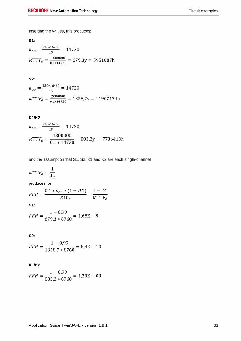
Circuit examples
Application Guide TwinSAFE - version 1.9.1 61
Inserting the values, this produces:
S1:
𝑛𝑜𝑝 =230∗16∗60
15= 14720
𝑀𝑇𝑇𝐹𝑑 =1000000
0,1∗14720= 679,3y = 5951087h
S2:
𝑛𝑜𝑝 =230∗16∗60
15= 14720
𝑀𝑇𝑇𝐹𝑑 =2000000
0,1∗14720= 1358,7y = 11902174h
K1/K2:
𝑛𝑜𝑝 =230∗16∗60
15= 14720
𝑀𝑇𝑇𝐹𝑑 =1300000
0,1 ∗ 14720= 883,2y = 7736413h
and the assumption that S1, S2, K1 and K2 are each single-channel:
𝑀𝑇𝑇𝐹𝑑 =1
𝜆𝑑
produces for
𝑃𝐹𝐻 =0,1 ∗ 𝑛𝑜𝑝 ∗ (1 − 𝐷𝐶)
𝐵10𝑑=
1 − DC
MTTFd
S1:
𝑃𝐹𝐻 =1 − 0,99
679,3 ∗ 8760= 1,68E − 9
S2:
𝑃𝐹𝐻 =1 − 0,99
1358,7 ∗ 8760= 8,4E − 10
K1/K2:
𝑃𝐹𝐻 =1 − 0,99
883,2 ∗ 8760= 1,29E − 09

Circuit examples
62 Application Guide TwinSAFE - version 1.9.1
The following assumptions must now be made:
The door switches S1/S2 are always actuated in opposite directions. Since the switches have different
values, but the complete protective door switch consists of a combination of normally closed and normally
open contacts and both switches must function, the poorer of the two values (S1) can be taken for the
combination!
Relays K1 and K2 are both connected to the safety function. The non-functioning of a relay does not lead
to a dangerous situation, but it is discovered by the feedback. Furthermore, the B10d values for K1 and
K2 are identical.
There is a coupling coefficient between the components that are connected via two channels. Examples
are temperature, EMC, voltage peaks or signals between these components. This is assumed to be the
worst-case estimation, where ß =10%. EN 62061 contains a table with which this ß-factor can be
precisely determined. Further, it is assumed that all usual measures have been taken to prevent both
channels failing unsafely at the same time due to an error (e.g. overcurrent through relay contacts,
overtemperature in the control cabinet).
This produces for the calculation of the PFH value for safety function 1:
𝑃𝐹𝐻𝑔𝑒𝑠 = 𝛽 ∗𝑃𝐹𝐻(𝑆1) + 𝑃𝐹𝐻(𝑆2)
2+ (1 − 𝛽)2 ∗ (𝑃𝐹𝐻(𝑆1) ∗ 𝑃𝐹𝐻(𝑆2)) ∗ 𝑇1 + 𝑃𝐹𝐻(𝐸𝐿1904) + 𝑃𝐹𝐻(𝐸𝐿6900)
+ 𝑃𝐹𝐻(𝐸𝐿2904) + 𝛽 ∗𝑃𝐹𝐻(𝐾1) + 𝑃𝐹𝐻(𝐾2)
2+ (1 − 𝛽)2 ∗ (𝑃𝐹𝐻(𝐾1) ∗ 𝑃𝐹𝐻(𝐾2)) ∗ 𝑇1 + 𝑃𝐹𝐻(𝐸𝐿1904)
Since the portions (1 − 𝛽)2 ∗ (𝑃𝐹𝐻(𝑆1) ∗ 𝑃𝐹𝐻(𝑆2)) ∗ 𝑇1 and (1 − 𝛽)2 ∗ (𝑃𝐹𝐻(𝐾1) ∗ 𝑃𝐹𝐻(𝐾2)) ∗ 𝑇1 are smaller
than the rest by the power of ten, they are neglected in this and all further calculations for the purpose of
simplification
to:
𝑃𝐹𝐻𝑔𝑒𝑠 = 10% ∗1,68𝐸 − 09 + 1,68𝐸 − 09
2+ 1,11𝐸 − 09 + 1,03𝐸 − 09 + 1,25𝐸 − 09 + 10%
∗1,29𝐸 − 09 + 1,29𝐸 − 09
2+ 1,11𝐸 − 09 = 4,80𝐸 − 09
The MTTFd value for safety function 1 (based on the same assumption) is calculated with:
1
𝑀𝑇𝑇𝐹𝑑 𝑔𝑒𝑠= ∑
1
𝑀𝑇𝑇𝐹𝑑 𝑛
𝑛
𝑖=1
as:
1
𝑀𝑇𝑇𝐹𝑑 𝑔𝑒𝑠
=1
𝑀𝑇𝑇𝐹𝑑 (𝑆1)+
1
𝑀𝑇𝑇𝐹𝑑(𝐸𝐿1904)+
1
𝑀𝑇𝑇𝐹𝑑 (𝐸𝐿6900)+
1
𝑀𝑇𝑇𝐹𝑑(𝐸𝐿2904)+
1
𝑀𝑇𝑇𝐹𝑑 (𝐾1)
+1
𝑀𝑇𝑇𝐹𝑑(𝐸𝐿1904)
with:
𝑀𝑇𝑇𝐹𝑑(S1) =𝐵10𝑑(𝑆1)
0,1 ∗ 𝑛𝑜𝑝
𝑀𝑇𝑇𝐹𝑑(S2) =𝐵10𝑑(𝑆2)
0,1 ∗ 𝑛𝑜𝑝
𝑀𝑇𝑇𝐹𝑑(K1) =𝐵10𝑑(𝐾1)
0,1 ∗ 𝑛𝑜𝑝

Circuit examples
Application Guide TwinSAFE - version 1.9.1 63
If only PFH values are available for EL1904, EL2904 and EL6900, the following estimation applies:
𝑀𝑇𝑇𝐹𝑑(ELxxxx) =(1 − 𝐷𝐶(𝐸𝐿𝑥𝑥𝑥))
𝑃𝐹𝐻(𝐸𝐿𝑥𝑥𝑥)
Hence:
𝑀𝑇𝑇𝐹𝑑(EL1904) =(1 − 𝐷𝐶(𝐸𝐿1904))
𝑃𝐹𝐻(𝐸𝐿1904)=
(1 − 0,99)
1,11E − 09 1
h∗ 8760h
y
=0,01
9,72E − 061
y
= 1028,8y
𝑀𝑇𝑇𝐹𝑑(EL6900) =(1 − 𝐷𝐶(𝐸𝐿6900))
𝑃𝐹𝐻(𝐸𝐿6900) =
(1 − 0,99)
1,03E − 091
h∗ 8760h
y
=0,01
9,02E − 061
y
= 1108,6y
𝑀𝑇𝑇𝐹𝑑(EL2904) =(1 − 𝐷𝐶(𝐸𝐿2904))
𝑃𝐹𝐻(𝐸𝐿2904) =
(1 − 0,99)
1,25E − 091
h∗ 8760h
y
=0,01
1,1E − 051
y
= 913,2y
𝑀𝑇𝑇𝐹𝐷𝑔𝑒𝑠 =1
1
679,3𝑦+ 1
1028,8𝑦+ 1
1108,6𝑦+ 1
913,2𝑦+ 1
883,2𝑦+ 1
1028,8𝑦
= 152,7𝑦
𝐷𝐶𝑎𝑣𝑔 =
99%
679,3+ 99%
1358,7+ 99%
1028,8+ 99%
1108,6+ 99%
913,2+ 99%
883,2+ 99%
883,2+ 99%
1028,81
679,3+ 1
1358,7+ 1
1028,8+ 1
1108,6+ 1
913,2+ 1
883,2+ 1
883,2+ 1
1028,8
= 99,0%
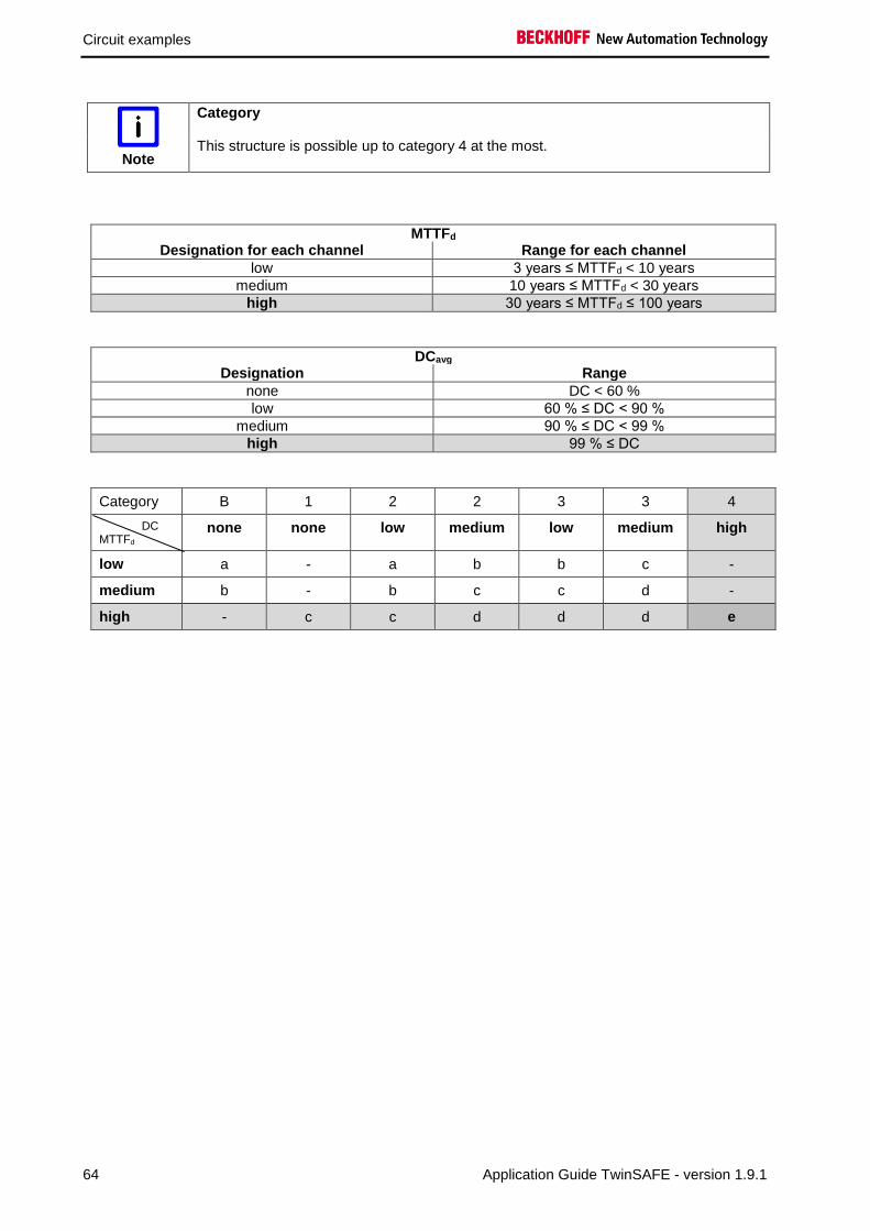
Circuit examples
64 Application Guide TwinSAFE - version 1.9.1
Note
Category
This structure is possible up to category 4 at the most.
MTTFd Designation for each channel Range for each channel
low 3 years ≤ MTTFd < 10 years
medium 10 years ≤ MTTFd < 30 years
high 30 years ≤ MTTFd ≤ 100 years
DCavg Designation Range
none DC < 60 %
low 60 % ≤ DC < 90 %
medium 90 % ≤ DC < 99 %
high 99 % ≤ DC
Category B 1 2 2 3 3 4
DC MTTFd
none none low medium low medium high
low a - a b b c -
medium b - b c c d -
high - c c d d d e

Circuit examples
Application Guide TwinSAFE - version 1.9.1 65
2.10 Protective door function with range monitoring (Category 4, PL e)
The protective door uses a combination of normally closed and normally open contacts on the safe inputs
of an EL1904. The testing of the inputs is active and the signals are tested for discrepancy (200 ms). The
feedback loop is read in via a safe input. The proximity switches S3 and S4 are wired to safe inputs and
detect, for example, when a dangerous machine part is in a safe position so that the protective door may
be opened when the machine is running. The testing of these inputs is deactivated so that the static 24 V
voltage of the sensors can be used.
The contactors K1 and K2 are connected in parallel to the safe output. Current measurement and testing
of the output are active for this circuit.
Unsafe position
K1
K2
Logical connection in
the EL6900
K1 K2
S3
S4
Safe position
Moving
machine part
Proximity
switch S3
Proximity
switch S4
Protective door S1, S2
Actuator
+24V
+24V
CLOSED
OPEN
S1
S2

Circuit examples
66 Application Guide TwinSAFE - version 1.9.1
2.10.1 Parameters of the safe input and output terminals
EL1904 (upper EL1904 on the drawing)
Parameter Value
Sensor test channel 1 active Yes
Sensor test channel 2 active Yes
Sensor test channel 3 active Yes
Sensor test channel 4 active Yes
Logic channel 1 and 2 Single Logic
Logic channel 3 and 4 Single Logic
EL1904 (lower EL1904 on the drawing)
Parameter Value
Sensor test channel 1 active No
Sensor test channel 2 active No
Sensor test channel 3 active Yes
Sensor test channel 4 active Yes
Logic channel 1 and 2 Single Logic
Logic channel 3 and 4 Single Logic
EL2904 (applies to all EL2904 used)
Parameter Value
Current measurement active Yes
Output test pulses active Yes
2.10.2 Block formation and safety loops
2.10.2.1 Safety function 1
EL1904
S1
S2
EL1904
S3
S4
K1
K2
EL6900 EL2904

Circuit examples
Application Guide TwinSAFE - version 1.9.1 67
2.10.3 Calculation
2.10.3.1 PFH / MTTFd /B10d – values
Component Value
EL1904 – PFH 1.11E-09
EL2904 – PFH 1.25E-09
EL6900 – PFH 1.03E-09
S1 – B10d 1,000,000
S2 – B10d 2,000,000
S3 – B10d 20,000,000
S4 – B10d 20,000,000
K1 – B10d 1,300,000
K2 – B10d 1,300,000
Days of operation (dop) 230
Hours of operation / day (hop) 16
Cycle time (minutes) (TZyklus) 15 (4x per hour)
Lifetime (T1) 20 years = 175200 hours
2.10.3.2 Diagnostic Coverage DC
Component Value
S1/S2 with testing/plausibility DCavg=99%
S3/S4 with without testing / with plausibility DCavg=90%
K1/K2 with testing and EDM DCavg=99%
2.10.3.3 Calculation for safety function 1
Calculation of the PFH and MTTFd values from the B10d values:
From:
𝑛𝑜𝑝 =𝑑𝑜𝑝∗ℎ𝑜𝑝∗60
𝑇𝑍𝑦𝑘𝑙𝑢𝑠
and:
𝑀𝑇𝑇𝐹𝑑 =𝐵10𝑑
0,1 ∗ 𝑛𝑜𝑝
Inserting the values, this produces:
S1:
𝑛𝑜𝑝 =230∗16∗60
15= 14720
𝑀𝑇𝑇𝐹𝑑 =1000000
0,1∗14720= 679,3y = 5951087h

Circuit examples
68 Application Guide TwinSAFE - version 1.9.1
S2:
𝑛𝑜𝑝 =230∗16∗60
15= 14720
𝑀𝑇𝑇𝐹𝑑 =2000000
0,1∗14720= 1358,7y = 11902174h
S3:
𝑛𝑜𝑝 =230∗16∗60
15= 14720
𝑀𝑇𝑇𝐹𝑑 =20000000
0,1∗14720= 13586,9y = 119021739h
S4:
𝑛𝑜𝑝 =230∗16∗60
15= 14720
𝑀𝑇𝑇𝐹𝑑 =20000000
0,1∗14720= 13586,9y = 119021739h
K1/K2:
𝑛𝑜𝑝 =230∗16∗60
15= 14720
𝑀𝑇𝑇𝐹𝑑 =1300000
0,1 ∗ 21,90= 883,2y = 7736413h
and the assumption that S1, S2, S3, S4, K1 and K2 are each single-channel:
𝑀𝑇𝑇𝐹𝑑 =1
𝜆𝑑
produces for
𝑃𝐹𝐻 =0,1 ∗ 𝑛𝑜𝑝 ∗ (1 − 𝐷𝐶)
𝐵10𝑑=
1 − DC
MTTFd
S1:
𝑃𝐹𝐻 =1 − 0,99
679,3 ∗ 8760= 1,68E − 9
S2:
𝑃𝐹𝐻 =1 − 0,99
1358,7 ∗ 8760= 8,4E − 10
S3/S4:
𝑃𝐹𝐻 =1 − 0,90
13586,9 ∗ 8760= 8,4E − 10
K1/K2:
𝑃𝐹𝐻 =1 − 0,99
883,2 ∗ 8760= 1,29E − 9

Circuit examples
Application Guide TwinSAFE - version 1.9.1 69
The following assumptions must now be made:
The door switches S1/S2 are always actuated in opposite directions. Since the switches have different
values, but the complete protective door switch consists of a combination of normally closed and normally
open contacts and both switches must function, the poorer of the two values (S1) can be taken for the
combination!
The proximity switches S3/S4 are monitored for plausibility (temporal/logical) and are type A systems
according to EN61508 (simple components whose behavior under error conditions is fully known). The
safe position is driven to once per shift.
Relays K1 and K2 are both connected to the safety function. The non-functioning of a relay does not lead
to a dangerous situation, but it is discovered by the feedback. Furthermore, the B10d values for K1 and
K2 are identical.
There is a coupling coefficient between the components that are connected via two channels. Examples
are temperature, EMC, voltage peaks or signals between these components. This is assumed to be the
worst-case estimation, where ß =10%. EN 62061 contains a table with which this ß-factor can be
precisely determined. Further, it is assumed that all usual measures have been taken to prevent both
channels failing unsafely at the same time due to an error (e.g. overcurrent through relay contacts,
overtemperature in the control cabinet).
This produces for the calculation of the PFH value for safety function 1:
𝑃𝐹𝐻𝑔𝑒𝑠 = 𝛽 ∗𝑃𝐹𝐻(𝑆1\𝑆2\𝐸𝐿1904) + 𝑃𝐹𝐻(𝑆3\𝑆4\𝐸𝐿1904)
2+ (1 − 𝛽)2 ∗ (𝑃𝐹𝐻(𝑆1\𝑆2\𝐸𝐿1904) ∗ 𝑃𝐹𝐻(𝑆3\𝑆4\𝐸𝐿1904)) ∗ 𝑇1
+ 𝑃𝐹𝐻(𝐸𝐿6900) + 𝑃𝐹𝐻(𝐸𝐿2904) + 𝛽 ∗𝑃𝐹𝐻(𝐾1) + 𝑃𝐹𝐻(𝐾2)
2+ (1 − 𝛽)2 ∗ (𝑃𝐹𝐻(𝐾1) ∗ 𝑃𝐹𝐻(𝐾2)) ∗ 𝑇1
Since the portions (1 − 𝛽)2 ∗ (𝑃𝐹𝐻(𝑆1\𝑆2\𝐸𝐿1904) ∗ 𝑃𝐹𝐻(𝑆3\𝑆4\𝐸𝐿1904)) ∗ 𝑇1 and (1 − 𝛽)2 ∗ (𝑃𝐹𝐻(𝐾1) ∗
𝑃𝐹𝐻(𝐾2)) ∗ 𝑇1 are smaller than the rest by the power of ten, they are neglected in this and all further
calculations for the purpose of simplification.
to:
𝑃𝐹𝐻(𝑆1\𝑆2\𝐸𝐿1904) = 𝛽 ∗𝑃𝐹𝐻(𝑆1) + 𝑃𝐹𝐻(𝑆2)
2+ 𝑃𝐹𝐻(𝐸𝐿1904) = 10% ∗
1,68𝐸 − 09 + 8,4𝐸 − 10
2+ 1,11𝐸 − 09
= 𝟏, 𝟐𝟒𝑬 − 𝟎𝟗
𝑃𝐹𝐻(𝑆3\𝑆4\𝐸𝐿1904) = 𝛽 ∗𝑃𝐹𝐻(𝑆3) + 𝑃𝐹𝐻(𝑆4)
2+ 𝑃𝐹𝐻(𝐸𝐿1904) = 10% ∗
8,4𝐸 − 10 + 8,4𝐸 − 10
2+ 1,11𝐸 − 09
= 𝟏, 𝟏𝟗𝑬 − 𝟎𝟗
𝑃𝐹𝐻𝑔𝑒𝑠 = 10% ∗1,24𝐸 − 09 + 1,19𝐸 − 09
2+ 1,03𝐸 − 09 + 1,25𝐸 − 09 + 10% ∗
1,29𝐸 − 09 + 1,29𝐸 − 09
2= 𝟐, 𝟓𝟑𝑬 − 𝟎𝟗
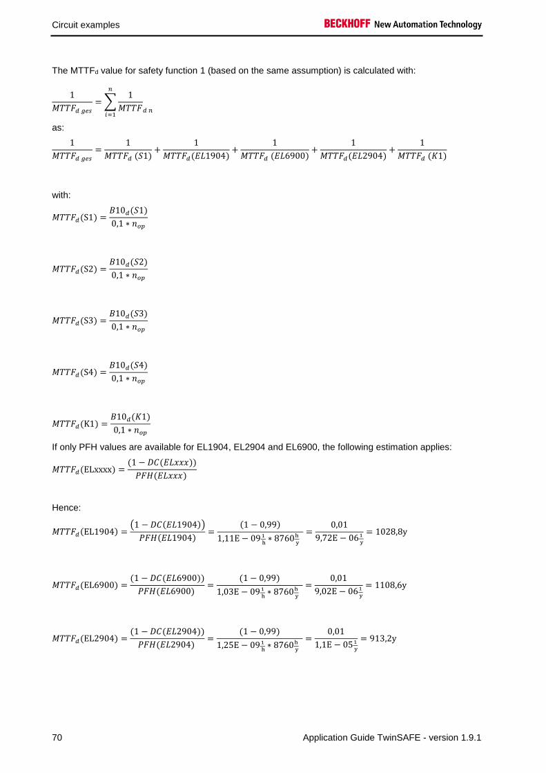
Circuit examples
70 Application Guide TwinSAFE - version 1.9.1
The MTTFd value for safety function 1 (based on the same assumption) is calculated with:
1
𝑀𝑇𝑇𝐹𝑑 𝑔𝑒𝑠
= ∑1
𝑀𝑇𝑇𝐹𝑑 𝑛
𝑛
𝑖=1
as:
1
𝑀𝑇𝑇𝐹𝑑 𝑔𝑒𝑠
=1
𝑀𝑇𝑇𝐹𝑑 (𝑆1)+
1
𝑀𝑇𝑇𝐹𝑑(𝐸𝐿1904)+
1
𝑀𝑇𝑇𝐹𝑑 (𝐸𝐿6900)+
1
𝑀𝑇𝑇𝐹𝑑(𝐸𝐿2904)+
1
𝑀𝑇𝑇𝐹𝑑 (𝐾1)
with:
𝑀𝑇𝑇𝐹𝑑(S1) =𝐵10𝑑(𝑆1)
0,1 ∗ 𝑛𝑜𝑝
𝑀𝑇𝑇𝐹𝑑(S2) =𝐵10𝑑(𝑆2)
0,1 ∗ 𝑛𝑜𝑝
𝑀𝑇𝑇𝐹𝑑(S3) =𝐵10𝑑(𝑆3)
0,1 ∗ 𝑛𝑜𝑝
𝑀𝑇𝑇𝐹𝑑(S4) =𝐵10𝑑(𝑆4)
0,1 ∗ 𝑛𝑜𝑝
𝑀𝑇𝑇𝐹𝑑(K1) =𝐵10𝑑(𝐾1)
0,1 ∗ 𝑛𝑜𝑝
If only PFH values are available for EL1904, EL2904 and EL6900, the following estimation applies:
𝑀𝑇𝑇𝐹𝑑(ELxxxx) =(1 − 𝐷𝐶(𝐸𝐿𝑥𝑥𝑥))
𝑃𝐹𝐻(𝐸𝐿𝑥𝑥𝑥)
Hence:
𝑀𝑇𝑇𝐹𝑑(EL1904) =(1 − 𝐷𝐶(𝐸𝐿1904))
𝑃𝐹𝐻(𝐸𝐿1904)=
(1 − 0,99)
1,11E − 09 1
h∗ 8760h
y
=0,01
9,72E − 061
y
= 1028,8y
𝑀𝑇𝑇𝐹𝑑(EL6900) =(1 − 𝐷𝐶(𝐸𝐿6900))
𝑃𝐹𝐻(𝐸𝐿6900) =
(1 − 0,99)
1,03E − 091
h∗ 8760h
y
=0,01
9,02E − 061
y
= 1108,6y
𝑀𝑇𝑇𝐹𝑑(EL2904) =(1 − 𝐷𝐶(𝐸𝐿2904))
𝑃𝐹𝐻(𝐸𝐿2904) =
(1 − 0,99)
1,25E − 091
h∗ 8760h
y
=0,01
1,1E − 051
y
= 913,2y

Circuit examples
Application Guide TwinSAFE - version 1.9.1 71
𝑀𝑇𝑇𝐹𝐷𝑔𝑒𝑠 =1
1
679,3𝑦+
1
1028,8𝑦+
1
1108,6𝑦+
1
913,2𝑦+
1
833,2𝑦
= 177,3𝑦
𝐷𝐶𝑎𝑣𝑔 =
99%
679,3+
99%
1358,7+
90%
13586,9+
90%
13586,9+
99%
1028,8+
99%
1028,8+
99%
1108,6+
99%
913,2+
99%
833,2+
99%
833,21
679,3+
1
1358,7+
1
13586,9+
1
13586,9+
1
1028,8+
1
1028,8+
1
1108,6+
1
913,2+
1
833,2+
1
833,2
= 98,85%
Note
Category
This structure is possible up to category 4 at the most. The monitoring of sensors S3
and S4 must be temporally and logically programmed.
MTTFd Designation for each channel Range for each channel
low 3 years ≤ MTTFd < 10 years
medium 10 years ≤ MTTFd < 30 years
high 30 years ≤ MTTFd ≤ 100 years
DCavg Designation Range
none DC < 60 %
low 60 % ≤ DC < 90 %
medium 90 % ≤ DC < 99 %
high 99 % ≤ DC
For practical usability, the number of the ranges was limited to four. An accuracy of 5% is assumed for
the limit values shown in this table.
Category B 1 2 2 3 3 4
DC MTTFd
none none low medium low medium high
low a - a b b c -
medium b - b c c d -
high - c c d d d e

Circuit examples
72 Application Guide TwinSAFE - version 1.9.1
2.11 Protective door function with guard lock (Category 4, PL e)
The protective door has two contacts, S1 ‘door closed’ and S2 ‘door closed and locked’, which are wired
to safe inputs of an EL1904. The testing of the inputs is active. Checking of the signals for discrepancy
cannot take place, because there is no temporal relationship between the signals. The feedback loop and
the restart signal are read in via a safe input. The testing of the inputs is active here also. The contactors
K1 and K2 are connected in parallel to the safe output. Current measurement and testing of the output
are active for this circuit.
The guard lock is switched via 2 safe inputs in which testing is active. Testing and current measurement
is active on the safe output for the guard lock.
CLOSED
OPEN
K1
K2
Unlock
Lock
Restart
S1
S2
Logical connection in
the EL6900
K1 K2
2.11.1 Parameters of the safe input and output terminals
EL1904 (applies to all EL1904 used)
Parameter Value
Sensor test channel 1 active Yes
Sensor test channel 2 active Yes
Sensor test channel 3 active Yes
Sensor test channel 4 active Yes
Logic channel 1 and 2 Single Logic
Logic channel 3 and 4 Single Logic

Circuit examples
Application Guide TwinSAFE - version 1.9.1 73
EL2904 (applies to all EL2904 used)
Parameter Value
Current measurement active Yes
Output test pulses active Yes
2.11.2 Block formation and safety loops
2.11.2.1 Safety function 1
2.11.3 Calculation
2.11.3.1 PFH / MTTFd /B10d – values
Component Value
EL1904 – PFH 1.11E-09
EL2904 – PFH 1.25E-09
EL6900 – PFH 1.03E-09
S1 – B10d 2,000,000
S2 – B10d 2,000,000
Restart - B10d 10,000,000
Lock – B10d 100,000
Unlock – B10d 100,000
K1 – B10d 1,300,000
K2 – B10d 1,300,000
Guard lock – B10d 2,000,000
Days of operation (dop) 230
Hours of operation / day (hop) 16
Cycle time (minutes) (TZyklus) 15 (4x per hour)
Lifetime (T1) 20 years = 175200 hours
EL1904 Restart
S1
S2
Lock
UnLock
EL2904 Guard-Lock
EL1904 EL6900
K1
K2
EL2904

Circuit examples
74 Application Guide TwinSAFE - version 1.9.1
2.11.3.2 Diagnostic Coverage DC
Component Value
S1 with testing DCavg=90%
S2 with testing and expectation DCavg=99%
Lock/unlock with testing/plausibility DCavg=99%
Restart DCavg=99%
K1/K2 with testing and EDM DCavg=99%
Guard Lock DCavg=99%
2.11.3.3 Calculation for safety function 1
Calculation of the PFH and MTTFd values from the B10d values:
From:
𝑛𝑜𝑝 =𝑑𝑜𝑝∗ℎ𝑜𝑝∗60
𝑇𝑍𝑦𝑘𝑙𝑢𝑠
and:
𝑀𝑇𝑇𝐹𝑑 =𝐵10𝑑
0,1 ∗ 𝑛𝑜𝑝
Inserting the values, this produces:
S1:
𝑛𝑜𝑝 =230∗16∗60
15= 14720
𝑀𝑇𝑇𝐹𝑑 =2000000
0,1∗14720= 1358,7y = 11902174h
S2:
𝑛𝑜𝑝 =230∗16∗60
15= 14720
𝑀𝑇𝑇𝐹𝑑 =2000000
0,1∗14720= 1358,7y = 11902174h
Lock/Unlock:
𝑛𝑜𝑝 =230∗16∗60
15= 14720
𝑀𝑇𝑇𝐹𝑑 =100000
0,1∗14720= 67,9y = 595108h
K1/K2:
𝑛𝑜𝑝 =230∗16∗60
15= 14720
𝑀𝑇𝑇𝐹𝑑 =1300000
0,1 ∗ 21,90= 883,2y = 7736413h

Circuit examples
Application Guide TwinSAFE - version 1.9.1 75
Restart:
𝑛𝑜𝑝 =230∗16∗60
15= 14720
𝑀𝑇𝑇𝐹𝑑 =10000000
0,1∗14720= 6793,5y = 59511060h
Guard lock:
𝑛𝑜𝑝 =230∗16∗60
15= 14720
𝑀𝑇𝑇𝐹𝑑 =2000000
0,1∗14720= 1358,7y = 11902173h
and the assumption that S1, S2, S3, S4, K1, K2 and the guard lock are each single-channel:
𝑀𝑇𝑇𝐹𝑑 =1
𝜆𝑑
produces for
𝑃𝐹𝐻 =0,1 ∗ 𝑛𝑜𝑝 ∗ (1 − 𝐷𝐶)
𝐵10𝑑=
1 − DC
MTTFd
S1:
𝑃𝐹𝐻 =1 − 0,90
1358,7 ∗ 8760= 8,40E − 09
S2:
𝑃𝐹𝐻 =1 − 0,99
1358,7 ∗ 8760= 8,40E − 10
Lock/Unlock:
𝑃𝐹𝐻 =1 − 0,99
67,9 ∗ 8760= 1,68E − 08
Restart:
𝑃𝐹𝐻 =1 − 0,90
6793,5 ∗ 8760= 1,68E − 09
K1/K2:
𝑃𝐹𝐻 =1 − 0,99
883,2 ∗ 8760= 1,29E − 09
Guard lock:
𝑃𝐹𝐻 =1 − 0,99
1358,7 ∗ 8760= 8,40E − 10

Circuit examples
76 Application Guide TwinSAFE - version 1.9.1
The following assumptions must now be made:
The door switches S1/S2 must both be actuated. Since the switches have different values, but the
complete protective door switch consists of a combination of normally closed and normally open contacts
and both switches must function, the poorer of the two values (S1) can be taken for the combination!
Relays K1 and K2 are both connected to the safety function. The non-functioning of a relay does not lead
to a dangerous situation, but it is discovered by the feedback. Furthermore, the B10d values for K1 and
K2 are identical.
The guard lock is mechanically connected to the switch S2 in such a way that a separation of the coupling
is impossible.
The restart is monitored, so that a signal change is only valid once the door is closed.
There is a coupling coefficient between the components that are connected via two channels. Examples
are temperature, EMC, voltage peaks or signals between these components. This is assumed to be the
worst-case estimation, where ß =10%. EN 62061 contains a table with which this ß-factor can be
precisely determined. Further, it is assumed that all usual measures have been taken to prevent both
channels failing unsafely at the same time due to an error (e.g. overcurrent through relay contacts,
overtemperature in the control cabinet).
This produces for the calculation of the PFH value for safety function 1:
𝑃𝐹𝐻𝑔𝑒𝑠 = 𝛽 ∗𝑃𝐹𝐻(𝑆2\𝐿𝑜𝑐𝑘\𝑈𝑛𝑙𝑜𝑐𝑘\𝐸𝐿2904\𝑍𝑢ℎ𝑎𝑙𝑡𝑢𝑛𝑔) + 𝑃𝐹𝐻(𝑆1)
2+ (1 − 𝛽)2
∗ (𝑃𝐹𝐻(𝑆2\𝐿𝑜𝑐𝑘\𝑈𝑛𝑙𝑜𝑐𝑘\𝐸𝐿2904\𝑍𝑢ℎ𝑎𝑙𝑡𝑢𝑛𝑔) ∗ 𝑃𝐹𝐻(𝑆1)) ∗ 𝑇1 + 𝑃𝐹𝐻(𝐸𝐿1904) + 𝑃𝐹𝐻(𝐸𝐿6900)
+ 𝑃𝐹𝐻(𝐸𝐿2904) + 𝛽 ∗𝑃𝐹𝐻(𝐾1) + 𝑃𝐹𝐻(𝐾2)
2+ (1 − 𝛽)2 ∗ (𝑃𝐹𝐻(𝐾1) ∗ 𝑃𝐹𝐻(𝐾2)) ∗ 𝑇1 + 𝑃𝐹𝐻(𝐸𝐿1904)
+ 𝑃𝐹𝐻(𝑅𝑒𝑠𝑡𝑎𝑟𝑡)
Since the portions (1 − 𝛽)2 ∗ (𝑃𝐹𝐻(𝑥) ∗ 𝑃𝐹𝐻(𝑦)) ∗ 𝑇1 are smaller than the rest by the power of ten, they are
neglected in this and all further calculations for the purpose of simplification.
to:
𝑃𝐹𝐻(𝑆2\𝐿𝑜𝑐𝑘\𝑈𝑛𝑙𝑜𝑐𝑘\𝐸𝐿2904\𝑍𝑢ℎ𝑎𝑙𝑡𝑢𝑛𝑔) = 𝑃𝐹𝐻(𝑆2) + 𝛽 ∗𝑃𝐹𝐻(𝐿𝑜𝑐𝑘) + 𝑃𝐹𝐻(𝑈𝑛𝑙𝑜𝑐𝑘)
2+ 𝑃𝐹𝐻(𝐸𝐿2904) + 𝑃𝐹𝐻(𝑍𝑢ℎ𝑎𝑙𝑡𝑢𝑛𝑔)
= 8,4𝐸 − 10 + 10% ∗1,68𝐸 − 08 + 1,68𝐸 − 08
2+ 1,25𝐸 − 09 + 8,4𝐸 − 10 = 𝟒, 𝟔𝟏𝑬 − 𝟎𝟗
𝑃𝐹𝐻𝑔𝑒𝑠 = 10% ∗4,61𝐸 − 09 + 8,4𝐸 − 09
2+ 1,11𝐸 − 09 + 1,03𝐸 − 09 + 1,25𝐸 − 09 + 10%
∗1,29𝐸 − 09 + 1,29𝐸 − 09
2+ 1,11𝐸 − 09 + 1,68𝐸 − 09 = 𝟔, 𝟗𝟔𝑬 − 𝟎𝟗
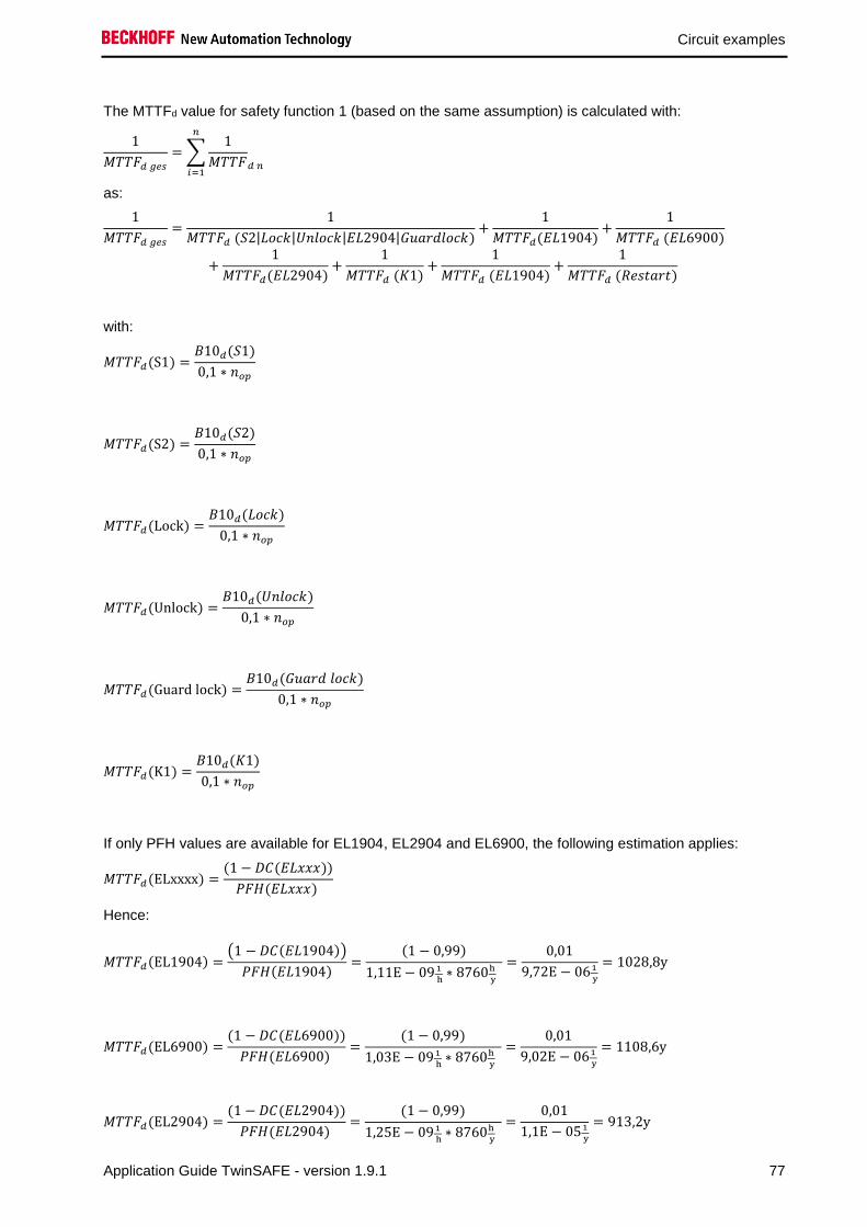
Circuit examples
Application Guide TwinSAFE - version 1.9.1 77
The MTTFd value for safety function 1 (based on the same assumption) is calculated with:
1
𝑀𝑇𝑇𝐹𝑑 𝑔𝑒𝑠
= ∑1
𝑀𝑇𝑇𝐹𝑑 𝑛
𝑛
𝑖=1
as:
1
𝑀𝑇𝑇𝐹𝑑 𝑔𝑒𝑠
=1
𝑀𝑇𝑇𝐹𝑑 (𝑆2|𝐿𝑜𝑐𝑘|𝑈𝑛𝑙𝑜𝑐𝑘|𝐸𝐿2904|𝐺𝑢𝑎𝑟𝑑𝑙𝑜𝑐𝑘)+
1
𝑀𝑇𝑇𝐹𝑑(𝐸𝐿1904)+
1
𝑀𝑇𝑇𝐹𝑑 (𝐸𝐿6900)
+1
𝑀𝑇𝑇𝐹𝑑(𝐸𝐿2904)+
1
𝑀𝑇𝑇𝐹𝑑 (𝐾1)+
1
𝑀𝑇𝑇𝐹𝑑 (𝐸𝐿1904)+
1
𝑀𝑇𝑇𝐹𝑑 (𝑅𝑒𝑠𝑡𝑎𝑟𝑡)
with:
𝑀𝑇𝑇𝐹𝑑(S1) =𝐵10𝑑(𝑆1)
0,1 ∗ 𝑛𝑜𝑝
𝑀𝑇𝑇𝐹𝑑(S2) =𝐵10𝑑(𝑆2)
0,1 ∗ 𝑛𝑜𝑝
𝑀𝑇𝑇𝐹𝑑(Lock) =𝐵10𝑑(𝐿𝑜𝑐𝑘)
0,1 ∗ 𝑛𝑜𝑝
𝑀𝑇𝑇𝐹𝑑(Unlock) =𝐵10𝑑(𝑈𝑛𝑙𝑜𝑐𝑘)
0,1 ∗ 𝑛𝑜𝑝
𝑀𝑇𝑇𝐹𝑑(Guard lock) =𝐵10𝑑(𝐺𝑢𝑎𝑟𝑑 𝑙𝑜𝑐𝑘)
0,1 ∗ 𝑛𝑜𝑝
𝑀𝑇𝑇𝐹𝑑(K1) =𝐵10𝑑(𝐾1)
0,1 ∗ 𝑛𝑜𝑝
If only PFH values are available for EL1904, EL2904 and EL6900, the following estimation applies:
𝑀𝑇𝑇𝐹𝑑(ELxxxx) =(1 − 𝐷𝐶(𝐸𝐿𝑥𝑥𝑥))
𝑃𝐹𝐻(𝐸𝐿𝑥𝑥𝑥)
Hence:
𝑀𝑇𝑇𝐹𝑑(EL1904) =(1 − 𝐷𝐶(𝐸𝐿1904))
𝑃𝐹𝐻(𝐸𝐿1904)=
(1 − 0,99)
1,11E − 09 1
h∗ 8760h
y
=0,01
9,72E − 061
y
= 1028,8y
𝑀𝑇𝑇𝐹𝑑(EL6900) =(1 − 𝐷𝐶(𝐸𝐿6900))
𝑃𝐹𝐻(𝐸𝐿6900) =
(1 − 0,99)
1,03E − 091
h∗ 8760h
y
=0,01
9,02E − 061
y
= 1108,6y
𝑀𝑇𝑇𝐹𝑑(EL2904) =(1 − 𝐷𝐶(𝐸𝐿2904))
𝑃𝐹𝐻(𝐸𝐿2904) =
(1 − 0,99)
1,25E − 091
h∗ 8760h
y
=0,01
1,1E − 051
y
= 913,2y

Circuit examples
78 Application Guide TwinSAFE - version 1.9.1
𝑀𝑇𝑇𝐹𝑑(S2|Lock|Unlock|EL2904|Guard lock)
=1
1
𝑀𝑇𝑇𝐹𝑑(𝑆2)+
1
𝑀𝑇𝑇𝐹𝑑(𝐿𝑜𝑐𝑘)+
1
𝑀𝑇𝑇𝐹𝑑(𝐸𝐿2904)+
1
𝑀𝑇𝑇𝐹𝑑(𝐺𝑢𝑎𝑟𝑑 𝑙𝑜𝑐𝑘)
= 1
1
1358,7𝑦+
1
67,9𝑦+
1
913,2𝑦+
1
1358,7𝑦
= 57,82𝑦
𝑀𝑇𝑇𝐹𝐷𝑔𝑒𝑠 =1
1
57,82𝑦+
1
1028,8𝑦+
1
1108,6𝑦+
1
913,2𝑦+
1
883,2𝑦+
1
1028,8𝑦+
1
6793,5𝑦
= 44,41𝑦
𝐷𝐶𝑎𝑣𝑔 =
99%
57,82+
99%
1358,7+
99%
67,9+
99%
67,9+
99%
913,2+
99%
1358,7+
99%
1028,8+
99%
1108,6+
99%
913,2+
99%
883,2+
99%
883,2+
99%
1028,8+
90%
6793,51
57,82+
1
1358,7+
1
67,9+
1
67,9+
1
913,2+
1
1358,7+
1
1028,8+
1
1108,6+
1
913,2+
1
883,2+
1
883,2+
1
1028,8+
1
6793,5
= 98,98%
Note
Category
This structure is possible up to category 4 at the most.
MTTFd Designation for each channel Range for each channel
low 3 years ≤ MTTFd < 10 years
medium 10 years ≤ MTTFd < 30 years
high 30 years ≤ MTTFd ≤ 100 years
DCavg Designation Range
none DC < 60 %
low 60 % ≤ DC < 90 %
medium 90 % ≤ DC < 99 %
high 99 % ≤ DC
Category B 1 2 2 3 3 4
DC MTTFd
none none low medium low medium high
low a - a b b c -
medium b - b c c d -
high - c c d d d e

Circuit examples
Application Guide TwinSAFE - version 1.9.1 79
2.12 Two-hand controller (Category 4, PL e)
The two-hand buttons each consist of a combination of normally closed and normally open contacts on
safe inputs of an EL1904. The testing of the inputs is active and the signals are tested for discrepancy
(200 ms). In addition, the synchronous actuation of the two buttons is activated with a monitoring time of
500 ms.
The feedback loop is read in via a safe input. The contactors K1 and K2 are connected in parallel to the
safe output. Current measurement and testing of the output are active for this circuit.
Logical connection in
the EL6900
K1 K2
K1
K2
S1
S2
2.12.1 Parameters of the safe input and output terminals
EL1904 (applies to all EL1904 used)
Parameter Value
Sensor test channel 1 active Yes
Sensor test channel 2 active Yes
Sensor test channel 3 active Yes
Sensor test channel 4 active Yes
Logic channel 1 and 2 Single Logic
Logic channel 3 and 4 Single Logic
EL2904
Parameter Value
Current measurement active Yes
Output test pulses active Yes
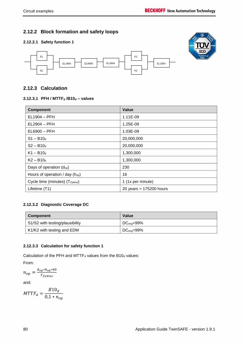
Circuit examples
80 Application Guide TwinSAFE - version 1.9.1
2.12.2 Block formation and safety loops
2.12.2.1 Safety function 1
2.12.3 Calculation
2.12.3.1 PFH / MTTFd /B10d – values
Component Value
EL1904 – PFH 1.11E-09
EL2904 – PFH 1.25E-09
EL6900 – PFH 1.03E-09
S1 – B10d 20,000,000
S2 – B10d 20,000,000
K1 – B10d 1,300,000
K2 – B10d 1,300,000
Days of operation (dop) 230
Hours of operation / day (hop) 16
Cycle time (minutes) (TZyklus) 1 (1x per minute)
Lifetime (T1) 20 years = 175200 hours
2.12.3.2 Diagnostic Coverage DC
Component Value
S1/S2 with testing/plausibility DCavg=99%
K1/K2 with testing and EDM DCavg=99%
2.12.3.3 Calculation for safety function 1
Calculation of the PFH and MTTFd values from the B10d values:
From:
𝑛𝑜𝑝 =𝑑𝑜𝑝∗ℎ𝑜𝑝∗60
𝑇𝑍𝑦𝑘𝑙𝑢𝑠
and:
𝑀𝑇𝑇𝐹𝑑 =𝐵10𝑑
0,1 ∗ 𝑛𝑜𝑝
K1
K2
EL1904 EL6900 EL2904
S1
S2
K1
K2
EL1904 EL6900 EL2904
S1
S2
EL1904

Circuit examples
Application Guide TwinSAFE - version 1.9.1 81
Inserting the values, this produces:
S1/S2:
𝑛𝑜𝑝 =230∗16∗60
1= 220800
𝑀𝑇𝑇𝐹𝑑 =20000000
0,1∗220800= 905,8y = 7934783h
K1/K2:
𝑛𝑜𝑝 =230∗16∗60
1= 220800
𝑀𝑇𝑇𝐹𝑑 =1300000
0,1 ∗ 220800= 58,9y = 515760h
and the assumption that S1, S2, K1 and K2 are each single-channel:
𝑀𝑇𝑇𝐹𝑑 =1
𝜆𝑑
produces for
𝑃𝐹𝐻 =0,1 ∗ 𝑛𝑜𝑝 ∗ (1 − 𝐷𝐶)
𝐵10𝑑=
1 − DC
MTTFd
S1/S2:
𝑃𝐹𝐻 =1 − 0,99
905,8y ∗ 8760= 1,26E − 09
K1/K2:
𝑃𝐹𝐻 =1 − 0,99
58,9 ∗ 8760= 1,93E − 8
The following assumptions must now be made:
Relays K1 and K2 are both connected to the safety function. The non-functioning of a relay does not lead
to a dangerous situation, but it is discovered by the feedback. Furthermore, the B10d values for K1 and
K2 are identical.
There is a coupling coefficient between the components that are connected via two channels. Examples
are temperature, EMC, voltage peaks or signals between these components. This is assumed to be the
worst-case estimation, where ß =10%. EN 62061 contains a table with which this ß-factor can be
precisely determined. Further, it is assumed that all usual measures have been taken to prevent both
channels failing unsafely at the same time due to an error (e.g. overcurrent through relay contacts,
overtemperature in the control cabinet).

Circuit examples
82 Application Guide TwinSAFE - version 1.9.1
This produces for the calculation of the PFH value for safety function 1:
𝑃𝐹𝐻𝑔𝑒𝑠 = 𝛽 ∗𝑃𝐹𝐻(𝑆1) + 𝑃𝐹𝐻(𝑆2)
2+ (1 − 𝛽)2 ∗ (𝑃𝐹𝐻(𝑆1) ∗ 𝑃𝐹𝐻(𝑆2)) ∗ 𝑇1 + 𝑃𝐹𝐻(𝐸𝐿1904) + 𝑃𝐹𝐻(𝐸𝐿6900)
+ 𝑃𝐹𝐻(𝐸𝐿2904) + 𝛽 ∗𝑃𝐹𝐻(𝐾1) + 𝑃𝐹𝐻(𝐾2)
2+ (1 − 𝛽)2 ∗ (𝑃𝐹𝐻(𝐾1) ∗ 𝑃𝐹𝐻(𝐾2)) ∗ 𝑇1 + 𝑃𝐹𝐻(𝐸𝐿1904)
Since the portions (1 − 𝛽)2 ∗ (𝑃𝐹𝐻(𝑆1) ∗ 𝑃𝐹𝐻(𝑆2)) ∗ 𝑇1 and (1 − 𝛽)2 ∗ (𝑃𝐹𝐻(𝐾1) ∗ 𝑃𝐹𝐻(𝐾2)) ∗ 𝑇1 are smaller
than the rest by the power of ten, they are neglected in this and all further calculations for the purpose of
simplification.
to:
𝑃𝐹𝐻𝑔𝑒𝑠 = 10% ∗1,26𝐸 − 09 + 1,26𝐸 − 09
2+ 1,11𝐸 − 09 + 1,03𝐸 − 09 + 1,25𝐸 − 09 + 10%
∗1,93𝐸 − 08 + 1,93𝐸 − 08
2+ 1,11𝐸 − 09 = 6,56𝐸 − 09
The MTTFd value for safety function 1 (based on the same assumption) is calculated with:
1
𝑀𝑇𝑇𝐹𝑑 𝑔𝑒𝑠
= ∑1
𝑀𝑇𝑇𝐹𝑑 𝑛
𝑛
𝑖=1
as:
1
𝑀𝑇𝑇𝐹𝑑 𝑔𝑒𝑠
=1
𝑀𝑇𝑇𝐹𝑑 (𝑆1)+
1
𝑀𝑇𝑇𝐹𝑑(𝐸𝐿1904)+
1
𝑀𝑇𝑇𝐹𝑑 (𝐸𝐿6900)+
1
𝑀𝑇𝑇𝐹𝑑(𝐸𝐿2904)+
1
𝑀𝑇𝑇𝐹𝑑 (𝐾1)
+1
𝑀𝑇𝑇𝐹𝑑(𝐸𝐿1904)
with:
𝑀𝑇𝑇𝐹𝑑(S1) =𝐵10𝑑(𝑆1)
0,1 ∗ 𝑛𝑜𝑝
𝑀𝑇𝑇𝐹𝑑(S2) =𝐵10𝑑(𝑆2)
0,1 ∗ 𝑛𝑜𝑝
𝑀𝑇𝑇𝐹𝑑(K1) =𝐵10𝑑(𝐾1)
0,1 ∗ 𝑛𝑜𝑝
If only PFH values are available for EL1904, EL2904 and EL6900, the following estimation applies:
𝑀𝑇𝑇𝐹𝑑(ELxxxx) =(1 − 𝐷𝐶(𝐸𝐿𝑥𝑥𝑥))
𝑃𝐹𝐻(𝐸𝐿𝑥𝑥𝑥)
Hence:
𝑀𝑇𝑇𝐹𝑑(EL1904) =(1 − 𝐷𝐶(𝐸𝐿1904))
𝑃𝐹𝐻(𝐸𝐿1904)=
(1 − 0,99)
1,11E − 09 1
h∗ 8760h
y
=0,01
9,72E − 061
y
= 1028,8y
𝑀𝑇𝑇𝐹𝑑(EL6900) =(1 − 𝐷𝐶(𝐸𝐿6900))
𝑃𝐹𝐻(𝐸𝐿6900) =
(1 − 0,99)
1,03E − 091
h∗ 8760h
y
=0,01
9,02E − 061
y
= 1108,6y
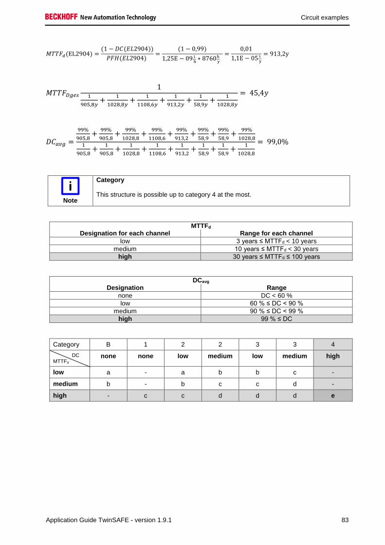
Circuit examples
Application Guide TwinSAFE - version 1.9.1 83
𝑀𝑇𝑇𝐹𝑑(EL2904) =(1 − 𝐷𝐶(𝐸𝐿2904))
𝑃𝐹𝐻(𝐸𝐿2904) =
(1 − 0,99)
1,25E − 091
h∗ 8760h
y
=0,01
1,1E − 051
y
= 913,2y
𝑀𝑇𝑇𝐹𝐷𝑔𝑒𝑠
11
905,8𝑦+
1
1028,8𝑦+
1
1108,6𝑦+
1
913,2𝑦+
1
58,9𝑦+
1
1028,8𝑦
= 45,4𝑦
𝐷𝐶𝑎𝑣𝑔 =
99%
905,8+
99%
905,8+
99%
1028,8+
99%
1108,6+
99%
913,2+
99%
58,9+
99%
58,9+
99%
1028,81
905,8+
1
905,8+
1
1028,8+
1
1108,6+
1
913,2+
1
58,9+
1
58,9+
1
1028,8
= 99,0%
Note
Category
This structure is possible up to category 4 at the most.
MTTFd Designation for each channel Range for each channel
low 3 years ≤ MTTFd < 10 years
medium 10 years ≤ MTTFd < 30 years
high 30 years ≤ MTTFd ≤ 100 years
DCavg Designation Range
none DC < 60 %
low 60 % ≤ DC < 90 %
medium 90 % ≤ DC < 99 %
high 99 % ≤ DC
Category B 1 2 2 3 3 4
DC MTTFd
none none low medium low medium high
low a - a b b c -
medium b - b c c d -
high - c c d d d e

Circuit examples
84 Application Guide TwinSAFE - version 1.9.1
2.13 Laser scanner (Category 3, PL d)
The laser scanner has two OSSD outputs (Output Signal Switching Device), which are wired to safe
inputs of a EL1904. The testing of the inputs is not active, since the OSSD outputs carry out their own
test. Furthermore, the signals are checked for discrepancy (200 ms). The feedback loop is read in via a
safe input. Testing is active for this input. The contactors K1 and K2 are connected in parallel to the safe
output. Current measurement and testing of the output are active for this circuit.
Logical connection in
the EL6900
K1 K2
K1
K2
OSSD 1
OSSD 2
2.13.1 Parameters of the safe input and output terminals
EL1904 (applies to all EL1904 used)
Parameter Value
Sensor test channel 1 active No
Sensor test channel 2 active No
Sensor test channel 3 active Yes
Sensor test channel 4 active Yes
Logic channel 1 and 2 OSSD any pulse repetition
Logic channel 3 and 4 Single Logic
EL2904
Parameter Value
Current measurement active Yes
Output test pulses active Yes

Circuit examples
Application Guide TwinSAFE - version 1.9.1 85
2.13.2 Block formation and safety loops
2.13.2.1 Safety function 1
2.13.3 Calculation
2.13.3.1 PFH / MTTFd /B10d – values
Component Value
EL1904 – PFH 1.11E-09
EL2904 – PFH 1.25E-09
EL6900 – PFH 1.03E-09
Laser scanner – PFHd 7.67E-08
K1 – B10d 1,300,000
K2 – B10d 1,300,000
Days of operation (dop) 230
Hours of operation / day (hop) 16
Cycle time (minutes) (TZyklus) 10 (6x per hour)
Lifetime (T1) 20 years = 175200 hours
2.13.3.2 Diagnostic Coverage DC
Component Value
OSSD1/2 with testing (by scanner) / plausibility DCavg=90%
K1/K2 with testing and EDM DCavg=99%
2.13.3.3 Calculation for safety function 1
Calculation of the PFH and MTTFd values from the B10d values:
From:
𝑛𝑜𝑝 =𝑑𝑜𝑝∗ℎ𝑜𝑝∗60
𝑇𝑍𝑦𝑘𝑙𝑢𝑠
and:
𝑀𝑇𝑇𝐹𝑑 =𝐵10𝑑
0,1 ∗ 𝑛𝑜𝑝
K1
K2
EL1904 EL6900 EL2904 Scanner

Circuit examples
86 Application Guide TwinSAFE - version 1.9.1
Inserting the values, this produces:
K1/K2:
𝑛𝑜𝑝 =230∗16∗60
10= 22080
𝑀𝑇𝑇𝐹𝑑 =1300000
0,1 ∗ 22080= 588,7y = 5157012h
and the assumption that K1 and K2 are each single-channel:
𝑀𝑇𝑇𝐹𝑑 =1
𝜆𝑑
produces for
𝑃𝐹𝐻 =0,1 ∗ 𝑛𝑜𝑝 ∗ (1 − 𝐷𝐶)
𝐵10𝑑=
1 − DC
MTTFd
K1/K2:
𝑃𝐹𝐻 =1 − 0,99
588,7 ∗ 8760= 1,94E − 9
The following assumptions must now be made:
Relays K1 and K2 are both connected to the safety function. The non-functioning of a relay does not lead
to a dangerous situation, but it is discovered by the feedback. Furthermore, the B10d values for K1 and
K2 are identical.
There is a coupling coefficient between the components that are connected via two channels. Examples
are temperature, EMC, voltage peaks or signals between these components. This is assumed to be the
worst-case estimation, where ß =10%. EN 62061 contains a table with which this ß-factor can be
precisely determined. Further, it is assumed that all usual measures have been taken to prevent both
channels failing unsafely at the same time due to an error (e.g. overcurrent through relay contacts,
overtemperature in the control cabinet).
This produces for the calculation of the PFH value for safety function 1:
𝑃𝐹𝐻𝑔𝑒𝑠 = 𝑃𝐹𝐻(𝑆𝑐𝑎𝑛𝑛𝑒𝑟) + 𝑃𝐹𝐻(𝐸𝐿1904) + 𝑃𝐹𝐻(𝐸𝐿6900) + 𝑃𝐹𝐻(𝐸𝐿2904) + 𝛽 ∗𝑃𝐹𝐻(𝐾1) + 𝑃𝐹𝐻(𝐾2)
2+ (1 − 𝛽)2 ∗ (𝑃𝐹𝐻(𝐾1) ∗ 𝑃𝐹𝐻(𝐾2)) ∗ 𝑇1
Since the portion (1 − 𝛽)2 ∗ (𝑃𝐹𝐻(𝐾1) ∗ 𝑃𝐹𝐻(𝐾2)) ∗ 𝑇1 is smaller than the rest by the power of ten, it is
neglected in this and all further calculations for the purpose of simplification.
to:
𝑃𝐹𝐻𝑔𝑒𝑠 = 7,67𝐸 − 08 + 1,11𝐸 − 09 + 1,03𝐸 − 09 + 1,25𝐸 − 09 + 10% ∗1,94𝐸 − 09 + 1,94𝐸 − 09
2= 8,03𝐸 − 08
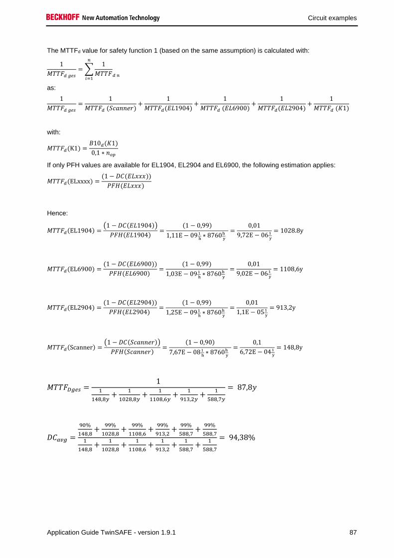
Circuit examples
Application Guide TwinSAFE - version 1.9.1 87
The MTTFd value for safety function 1 (based on the same assumption) is calculated with:
1
𝑀𝑇𝑇𝐹𝑑 𝑔𝑒𝑠
= ∑1
𝑀𝑇𝑇𝐹𝑑 𝑛
𝑛
𝑖=1
as:
1
𝑀𝑇𝑇𝐹𝑑 𝑔𝑒𝑠
=1
𝑀𝑇𝑇𝐹𝑑 (𝑆𝑐𝑎𝑛𝑛𝑒𝑟)+
1
𝑀𝑇𝑇𝐹𝑑(𝐸𝐿1904)+
1
𝑀𝑇𝑇𝐹𝑑 (𝐸𝐿6900)+
1
𝑀𝑇𝑇𝐹𝑑(𝐸𝐿2904)+
1
𝑀𝑇𝑇𝐹𝑑 (𝐾1)
with:
𝑀𝑇𝑇𝐹𝑑(K1) =𝐵10𝑑(𝐾1)
0,1 ∗ 𝑛𝑜𝑝
If only PFH values are available for EL1904, EL2904 and EL6900, the following estimation applies:
𝑀𝑇𝑇𝐹𝑑(ELxxxx) =(1 − 𝐷𝐶(𝐸𝐿𝑥𝑥𝑥))
𝑃𝐹𝐻(𝐸𝐿𝑥𝑥𝑥)
Hence:
𝑀𝑇𝑇𝐹𝑑(EL1904) =(1 − 𝐷𝐶(𝐸𝐿1904))
𝑃𝐹𝐻(𝐸𝐿1904)=
(1 − 0,99)
1,11E − 09 1
h∗ 8760h
y
=0,01
9,72E − 061
y
= 1028.8y
𝑀𝑇𝑇𝐹𝑑(EL6900) =(1 − 𝐷𝐶(𝐸𝐿6900))
𝑃𝐹𝐻(𝐸𝐿6900) =
(1 − 0,99)
1,03E − 091
h∗ 8760h
y
=0,01
9,02E − 061
y
= 1108,6y
𝑀𝑇𝑇𝐹𝑑(EL2904) =(1 − 𝐷𝐶(𝐸𝐿2904))
𝑃𝐹𝐻(𝐸𝐿2904) =
(1 − 0,99)
1,25E − 091
h∗ 8760h
y
=0,01
1,1E − 051
y
= 913,2y
𝑀𝑇𝑇𝐹𝑑(Scanner) =(1 − 𝐷𝐶(𝑆𝑐𝑎𝑛𝑛𝑒𝑟))
𝑃𝐹𝐻(𝑆𝑐𝑎𝑛𝑛𝑒𝑟)=
(1 − 0,90)
7,67E − 08 1
h∗ 8760h
y
=0,1
6,72E − 041
y
= 148,8y
𝑀𝑇𝑇𝐹𝐷𝑔𝑒𝑠 =1
1
148,8𝑦+
1
1028,8𝑦+
1
1108,6𝑦+
1
913,2𝑦+
1
588,7𝑦
= 87,8𝑦
𝐷𝐶𝑎𝑣𝑔 =
90%
148,8+
99%
1028,8+
99%
1108,6+
99%
913,2+
99%
588,7+
99%
588,71
148,8+
1
1028,8+
1
1108,6+
1
913,2+
1
588,7+
1
588,7
= 94,38%

Circuit examples
88 Application Guide TwinSAFE - version 1.9.1
Note
Category
This structure is possible up to category 3 at the most through the use of the type 3
(category 3) laser scanner.
MTTFd Designation for each channel Range for each channel
low 3 years ≤ MTTFd < 10 years
medium 10 years ≤ MTTFd < 30 years
high 30 years ≤ MTTFd ≤ 100 years
DCavg Designation Range
none DC < 60 %
low 60 % ≤ DC < 90 %
medium 90 % ≤ DC < 99 %
high 99 % ≤ DC
Category B 1 2 2 3 3 4
DC MTTFd
none none low medium low medium high
low a - a b b c -
medium b - b c c d -
high - c c d d d e

Circuit examples
Application Guide TwinSAFE - version 1.9.1 89
2.14 Light grid (Category 4, PL e)
The light grid has two OSSD outputs (Output-Signal-Switching-Device), which are wired to safe inputs of
an EL1904. The testing of the inputs is not active, since the OSSD outputs carry out their own test.
Furthermore, the signals are checked for discrepancy (200 ms). The feedback loop is read in via a safe
input. Testing is active for this input. The contactors K1 and K2 are connected in parallel to the safe
output. Current measurement and testing of the output are active for this circuit.
Logical connection in
the EL6900
K1 K2
K1
K2
OSSD 1
OSSD 2
2.14.1 Parameters of the safe input and output terminals
EL1904
Parameter Value
Sensor test channel 1 active No
Sensor test channel 2 active No
Sensor test channel 3 active Yes
Sensor test channel 4 active Yes
Logic channel 1 and 2 Asynchronous evaluation OSSD
Logic channel 3 and 4 Single Logic
EL2904
Parameter Value
Current measurement active Yes
Output test pulses active Yes

Circuit examples
90 Application Guide TwinSAFE - version 1.9.1
2.14.2 Block formation and safety loops
2.14.2.1 Safety function 1
2.14.3 Calculation
2.14.3.1 PFH / MTTFd /B10d – values
Component Value
EL1904 – PFH 1.11E-09
EL2904 – PFH 1.25E-09
EL6900 – PFH 1.03E-09
Light grid – PFHd 1.50E-08
K1 – B10d 1,300,000
K2 – B10d 1,300,000
Days of operation (dop) 230
Hours of operation / day (hop) 16
Cycle time (minutes) (TZyklus) 5 (12x per hour)
Lifetime (T1) 20 years = 175200 hours
2.14.3.2 Diagnostic Coverage DC
Component Value
OSSD1/2 with testing (by light grid) / plausibility DCavg=99%
K1/K2 with testing and EDM DCavg=99%
2.14.3.3 Calculation for safety function 1
Calculation of the PFH and MTTFd values from the B10d values:
From:
𝑛𝑜𝑝 =𝑑𝑜𝑝∗ℎ𝑜𝑝∗60
𝑇𝑍𝑦𝑘𝑙𝑢𝑠
and:
𝑀𝑇𝑇𝐹𝑑 =𝐵10𝑑
0,1 ∗ 𝑛𝑜𝑝
K1
K2
EL1904 EL6900 EL2904 Light-
grid

Circuit examples
Application Guide TwinSAFE - version 1.9.1 91
Inserting the values, this produces:
K1/K2:
𝑛𝑜𝑝 =230∗16∗60
5= 44160
𝑀𝑇𝑇𝐹𝑑 =1300000
0,1 ∗ 44160= 294,4y = 2578944h
and the assumption that K1 and K2 are each single-channel:
𝑀𝑇𝑇𝐹𝑑 =1
𝜆𝑑
produces for
𝑃𝐹𝐻 =0,1 ∗ 𝑛𝑜𝑝 ∗ (1 − 𝐷𝐶)
𝐵10𝑑=
1 − DC
MTTFd
K1/K2:
𝑃𝐹𝐻 =1 − 0,99
294,4 ∗ 8760= 3,88E − 9
The following assumptions must now be made:
Relays K1 and K2 are both connected to the safety function. The non-functioning of a relay does not lead
to a dangerous situation, but it is discovered by the feedback. Furthermore, the B10d values for K1 and
K2 are identical.
There is a coupling coefficient between the components that are connected via two channels. Examples
are temperature, EMC, voltage peaks or signals between these components. This is assumed to be the
worst-case estimation, where ß =10%. EN 62061 contains a table with which this ß-factor can be
precisely determined. Further, it is assumed that all usual measures have been taken to prevent both
channels failing unsafely at the same time due to an error (e.g. overcurrent through relay contacts,
overtemperature in the control cabinet).
This produces for the calculation of the PFH value for safety function 1:
𝑃𝐹𝐻𝑔𝑒𝑠 = 𝑃𝐹𝐻(𝐿𝑖𝑐ℎ𝑡 𝑔𝑟𝑖𝑑) + 𝑃𝐹𝐻(𝐸𝐿1904) + 𝑃𝐹𝐻(𝐸𝐿6900) + 𝑃𝐹𝐻(𝐸𝐿2904) + 𝛽 ∗𝑃𝐹𝐻(𝐾1) + 𝑃𝐹𝐻(𝐾2)
2+ (1 − 𝛽)2 ∗ (𝑃𝐹𝐻(𝐾1) ∗ 𝑃𝐹𝐻(𝐾2)) ∗ 𝑇1
Since the portion (1 − 𝛽)2 ∗ (𝑃𝐹𝐻(𝐾1) ∗ 𝑃𝐹𝐻(𝐾2)) ∗ 𝑇1 is smaller than the rest by the power of ten, it is
neglected in this and all further calculations for the purpose of simplification.
to:
𝑃𝐹𝐻𝑔𝑒𝑠 = 1,50𝐸 − 08 + 1,11𝐸 − 09 + 1,03𝐸 − 09 + 1,25𝐸 − 09 + 10% ∗3,88𝐸 − 09 + 3,88𝐸 − 09
2= 𝟏, 𝟖𝟖𝑬 − 𝟎𝟖

Circuit examples
92 Application Guide TwinSAFE - version 1.9.1
The MTTFd value for safety function 1 (based on the same assumption) is calculated with:
1
𝑀𝑇𝑇𝐹𝑑 𝑔𝑒𝑠
= ∑1
𝑀𝑇𝑇𝐹𝑑 𝑛
𝑛
𝑖=1
as:
1
𝑀𝑇𝑇𝐹𝑑 𝑔𝑒𝑠
=1
𝑀𝑇𝑇𝐹𝑑 (𝐿𝑖𝑔ℎ𝑡 𝑔𝑟𝑖𝑑)+
1
𝑀𝑇𝑇𝐹𝑑(𝐸𝐿1904)+
1
𝑀𝑇𝑇𝐹𝑑 (𝐸𝐿6900)+
1
𝑀𝑇𝑇𝐹𝑑(𝐸𝐿2904)+
1
𝑀𝑇𝑇𝐹𝑑 (𝐾1)
with:
𝑀𝑇𝑇𝐹𝑑(K1) =𝐵10𝑑(𝐾1)
0,1 ∗ 𝑛𝑜𝑝
If only PFH values are available for EL1904, EL2904 and EL6900, the following estimation applies:
𝑀𝑇𝑇𝐹𝑑(ELxxxx) =(1 − 𝐷𝐶(𝐸𝐿𝑥𝑥𝑥))
𝑃𝐹𝐻(𝐸𝐿𝑥𝑥𝑥)
Hence:
𝑀𝑇𝑇𝐹𝑑(EL1904) =(1 − 𝐷𝐶(𝐸𝐿1904))
𝑃𝐹𝐻(𝐸𝐿1904)=
(1 − 0,99)
1,11E − 09 1
h∗ 8760h
y
=0,01
9,72E − 061
y
= 1028.8y
𝑀𝑇𝑇𝐹𝑑(EL6900) =(1 − 𝐷𝐶(𝐸𝐿6900))
𝑃𝐹𝐻(𝐸𝐿6900) =
(1 − 0,99)
1,03E − 091
h∗ 8760h
y
=0,01
9,02E − 061
y
= 1108,6y
𝑀𝑇𝑇𝐹𝑑(EL2904) =(1 − 𝐷𝐶(𝐸𝐿2904))
𝑃𝐹𝐻(𝐸𝐿2904) =
(1 − 0,99)
1,25E − 091
h∗ 8760h
y
=0,01
1,1E − 051
y
= 913,2y
𝑀𝑇𝑇𝐹𝑑(Light grid) =(1 − 𝐷𝐶(Light grid))
𝑃𝐹𝐻(Light grid)=
(1 − 0,99)
1,50E − 08 1
h∗ 8760h
y
=0,01
1,31E − 041
y
= 76,1y
𝑀𝑇𝑇𝐹𝐷𝑔𝑒𝑠 =1
1
76,1𝑦+
1
1028,8𝑦+
1
1108,6𝑦+
1
913,2𝑦+
1
294,4𝑦
= 51,3𝑦
𝐷𝐶𝑎𝑣𝑔 =
99%
76,1+
99%
1028,8+
99%
1108,6+
99%
913,2+
99%
588,7+
99%
294,41
76,1+
1
1028,8+
1
1108,6+
1
913,2+
1
588,7+
1
294,4
= 99,0%

Circuit examples
Application Guide TwinSAFE - version 1.9.1 93
Note
Category
This structure is possible up to category 4 at the most through the use of the type 4
(category 4) light grid.
MTTFd Designation for each channel Range for each channel
low 3 years ≤ MTTFd < 10 years
medium 10 years ≤ MTTFd < 30 years
high 30 years ≤ MTTFd ≤ 100 years
DCavg Designation Range
none DC < 60 %
low 60 % ≤ DC < 90 %
medium 90 % ≤ DC < 99 %
high 99 % ≤ DC
Category B 1 2 2 3 3 4
DC MTTFd
none none low medium low medium high
low a - a b b c -
medium b - b c c d -
high - c c d d d e

Circuit examples
94 Application Guide TwinSAFE - version 1.9.1
2.15 Safety switching mat / safety bumper (Category 4, PL e)
Safety switching mats or safety bumpers work according to the cross-circuit principle. The contact
surfaces of the device are wired to safe inputs of an EL1904. The testing of the inputs is active and the
signals are tested for discrepancy (200 ms). As soon as a cross-circuit between the signals is detected
(safety mat is stepped on), a logical 0 is signaled by the EL1904 input terminal. If the cross-circuit is no
longer present, a logical 1 is signaled. The feedback loop is read in via a safe input. The testing of the
input is active here also. The contactors K1 and K2 are connected in parallel to the safe output. Current
measurement and testing of the output are active for this circuit.
Logical connection in
the EL6900
K1 K2
K1
K2
2.15.1 Parameters of the safe input and output terminals
EL1904 (applies to all EL1904 used)
Parameter Value
Sensor test channel 1 active Yes
Sensor test channel 2 active Yes
Sensor test channel 3 active Yes
Sensor test channel 4 active Yes
Logic channel 1 and 2 Cross-circuit is not a module error
Logic channel 3 and 4 Single Logic
EL2904
Parameter Value
Current measurement active Yes
Output test pulses active Yes

Circuit examples
Application Guide TwinSAFE - version 1.9.1 95
2.15.2 Block formation and safety loops
2.15.2.1 Safety function 1
2.15.3 Calculation
2.15.3.1 PFH / MTTFd /B10d – values
Component Value
EL1904 – PFH 1.11E-09
EL2904 – PFH 1.25E-09
EL6900 – PFH 1.03E-09
Switching mat – B10d 6.00E06
K1 – B10d 1,300,000
K2 – B10d 1,300,000
Days of operation (dop) 230
Hours of operation / day (hop) 16
Cycle time (minutes) (TZyklus) 1 (1x per minute)
Lifetime (T1) 20 years = 175200 hours
2.15.3.2 Diagnostic Coverage DC
Component Value
Switching outputs (mat) with testing/plausibility DCavg=99%
K1/K2 with testing and EDM DCavg=99%
2.15.3.3 Calculation for safety function 1
Calculation of the PFH and MTTFd values from the B10d values:
From:
𝑛𝑜𝑝 =𝑑𝑜𝑝∗ℎ𝑜𝑝∗60
𝑇𝑍𝑦𝑘𝑙𝑢𝑠
and:
𝑀𝑇𝑇𝐹𝑑 =𝐵10𝑑
0,1 ∗ 𝑛𝑜𝑝
K1
K2
EL1904 EL6900 EL2904 Safety
mat

Circuit examples
96 Application Guide TwinSAFE - version 1.9.1
Inserting the values, this produces:
K1/K2:
𝑛𝑜𝑝 =230∗16∗60
1= 220800
𝑀𝑇𝑇𝐹𝑑 =1300000
0,1 ∗ 220800= 58,9y = 515761h
Switching mat:
𝑛𝑜𝑝 =230∗16∗60
1= 220800
𝑀𝑇𝑇𝐹𝑑 =6,00E06
0,1 ∗ 220800= 271,7y = 2380434h
and the assumption that K1 and K2 are each single-channel:
𝑀𝑇𝑇𝐹𝑑 =1
𝜆𝑑
produces for
𝑃𝐹𝐻 =0,1 ∗ 𝑛𝑜𝑝 ∗ (1 − 𝐷𝐶)
𝐵10𝑑=
1 − DC
MTTFd
K1/K2:
𝑃𝐹𝐻 =1 − 0,99
58,9 ∗ 8760= 1,94E − 08
Switching mat:
𝑃𝐹𝐻 =1 − 0,99
271,7 ∗ 8760= 4,20E − 09
The following assumptions must now be made:
Relays K1 and K2 are both connected to the safety function. The non-functioning of a relay does not lead
to a dangerous situation, but it is discovered by the feedback. Furthermore, the B10d values for K1 and
K2 are identical.
There is a coupling coefficient between the components that are connected via two channels. Examples
are temperature, EMC, voltage peaks or signals between these components. This is assumed to be the
worst-case estimation, where ß =10%. EN 62061 contains a table with which this ß-factor can be
precisely determined. Further, it is assumed that all usual measures have been taken to prevent both
channels failing unsafely at the same time due to an error (e.g. overcurrent through relay contacts,
overtemperature in the control cabinet).
This produces for the calculation of the PFH value for safety function 1:
𝑃𝐹𝐻𝑔𝑒𝑠 = 𝑃𝐹𝐻(𝑠𝑤𝑖𝑡𝑐ℎ𝑖𝑛𝑔 𝑚𝑎𝑡) + 𝑃𝐹𝐻(𝐸𝐿1904) + 𝑃𝐹𝐻(𝐸𝐿6900) + 𝑃𝐹𝐻(𝐸𝐿2904) + 𝛽 ∗𝑃𝐹𝐻(𝐾1) + 𝑃𝐹𝐻(𝐾2)
2+ (1 − 𝛽)2 ∗ (𝑃𝐹𝐻(𝐾1) ∗ 𝑃𝐹𝐻(𝐾2)) ∗ 𝑇1

Circuit examples
Application Guide TwinSAFE - version 1.9.1 97
Since the portion (1 − 𝛽)2 ∗ (𝑃𝐹𝐻(𝐾1) ∗ 𝑃𝐹𝐻(𝐾2)) ∗ 𝑇1 is smaller than the rest by the power of ten, it is
neglected in this and all further calculations for the purpose of simplification.
to:
𝑃𝐹𝐻𝑔𝑒𝑠 = 4,20𝐸 − 09 + 1,11𝐸 − 09 + 1,03𝐸 − 09 + 1,25𝐸 − 09 + 10% ∗1,94𝐸 − 08 + 1,94𝐸 − 08
2= 𝟗, 𝟓𝟑𝑬 − 𝟎𝟗
The MTTFd value for block 1 (based on the same assumption) is calculated with:
1
𝑀𝑇𝑇𝐹𝑑 𝑔𝑒𝑠
= ∑1
𝑀𝑇𝑇𝐹𝑑 𝑛
𝑛
𝑖=1
as:
1
𝑀𝑇𝑇𝐹𝑑 𝑔𝑒𝑠
=1
𝑀𝑇𝑇𝐹𝑑 (𝑆𝑤𝑖𝑡𝑐ℎ𝑖𝑛𝑔 𝑚𝑎𝑡)+
1
𝑀𝑇𝑇𝐹𝑑(𝐸𝐿1904)+
1
𝑀𝑇𝑇𝐹𝑑 (𝐸𝐿6900)+
1
𝑀𝑇𝑇𝐹𝑑(𝐸𝐿2904)
+1
𝑀𝑇𝑇𝐹𝑑 (𝐾1)
with:
𝑀𝑇𝑇𝐹𝑑(K1) =𝐵10𝑑(𝐾1)
0,1 ∗ 𝑛𝑜𝑝
If only PFH values are available for EL1904, EL2904 and EL6900, the following estimation applies:
𝑀𝑇𝑇𝐹𝑑(ELxxxx) =(1 − 𝐷𝐶(𝐸𝐿𝑥𝑥𝑥))
𝑃𝐹𝐻(𝐸𝐿𝑥𝑥𝑥)
Hence:
𝑀𝑇𝑇𝐹𝑑(EL1904) =(1 − 𝐷𝐶(𝐸𝐿1904))
𝑃𝐹𝐻(𝐸𝐿1904)=
(1 − 0,99)
1,11E − 09 1
h∗ 8760h
y
=0,01
9,72E − 061
y
= 1028.8y
𝑀𝑇𝑇𝐹𝑑(EL6900) =(1 − 𝐷𝐶(𝐸𝐿6900))
𝑃𝐹𝐻(𝐸𝐿6900) =
(1 − 0,99)
1,03E − 091
h∗ 8760h
y
=0,01
9,02E − 061
y
= 1108,6y
𝑀𝑇𝑇𝐹𝑑(EL2904) =(1 − 𝐷𝐶(𝐸𝐿2904))
𝑃𝐹𝐻(𝐸𝐿2904) =
(1 − 0,99)
1,25E − 091
h∗ 8760h
y
=0,01
1,1E − 051
y
= 913,2y
𝑀𝑇𝑇𝐹𝐷𝑔𝑒𝑠 =1
1
271,7𝑦+
1
1028,8𝑦+
1
1108,6𝑦+
1
913,2𝑦+
1
58,9𝑦
= 42,3𝑦
𝐷𝐶𝑎𝑣𝑔 =
99%
271,7+
99%
1028,8+
99%
1108,6+
99%
913,2+
99%
58,9+
99%
58,91
271,7+
1
1028,8+
1
1108,6+
1
913,2+
1
58,9+
1
58,9
= 99,0%

Circuit examples
98 Application Guide TwinSAFE - version 1.9.1
Note
Category
Category 4 is attainable due to the structure of the circuit.
MTTFd Designation for each channel Range for each channel
low 3 years ≤ MTTFd < 10 years
medium 10 years ≤ MTTFd < 30 years
high 30 years ≤ MTTFd ≤ 100 years
DCavg Designation Range
none DC < 60 %
low 60 % ≤ DC < 90 %
medium 90 % ≤ DC < 99 %
high 99 % ≤ DC
Category B 1 2 2 3 3 4
DC MTTFd
none none low medium low medium high
low a - a b b c -
medium b - b c c d -
high - c c d d d e

Circuit examples
Application Guide TwinSAFE - version 1.9.1 99
2.16 Muting (Category 4, PL e)
The light grid has two OSSD outputs (Output-Signal-Switching-Device), which are wired to safe inputs of
an EL1904. The testing of the inputs is not active, since the OSSD outputs carry out their own test.
Furthermore, the signals are checked for discrepancy (200 ms). The feedback loop is read in via a safe
input. The muting switches and the enable switch are also wired to safe inputs. Testing is active for these
inputs.
The contactors K1 and K2 are connected in parallel to a safe output. The muting lamp is also wired to a
safe output. Current measurement and testing of the output are active for this circuit.
Logical connection in
the EL6900
K1 K2
K1
K2
OSSD 1
OSSD 2
MS1
MS3 MS4
MS2
S1
2.16.1 Parameters of the safe input and output terminals
EL1904 (upper terminal on the drawing)
Parameter Value
Sensor test channel 1 active No
Sensor test channel 2 active No
Sensor test channel 3 active Yes
Sensor test channel 4 active Yes
Logic channel 1 and 2 Asynchronous evaluation OSSD
Logic channel 3 and 4 Single Logic
EL1904 (lower terminal on the drawing)
Parameter Value
Sensor test channel 1 active Yes
Sensor test channel 2 active Yes
Sensor test channel 3 active Yes
Sensor test channel 4 active Yes
Logic channel 1 and 2 Single Logic
Logic channel 3 and 4 Single Logic

Circuit examples
100 Application Guide TwinSAFE - version 1.9.1
EL2904
Parameter Value
Current measurement active Yes
Output test pulses active Yes
2.16.2 Block formation and safety loops
2.16.2.1 Safety function 1
2.16.3 Calculation
2.16.3.1 PFH / MTTFd /B10d – values
Component Value
EL1904 – PFH 1.11E-09
EL2904 – PFH 1.25E-09
EL6900 – PFH 1.03E-09
S1 – B10d 100,000
Light curtain – PFHd 1.50E-08
MS1 – B10d 100,000
MS2 – B10d 100,000
MS3 – B10d 100,000
MS4 – B10d 100,000
K1 – B10d 1,300,000
K2 – B10d 1,300,000
Days of operation (dop) 230
Hours of operation / day (hop) 8
Cycle time (minutes) (TZyklus) 60 (1x per hour)
Lifetime (T1) 20 years = 175200 hours
K1
K2
EL1904 EL6900 EL2904 Light
curtain
MS
MS
MS
MS
EL1904 S1

Circuit examples
Application Guide TwinSAFE - version 1.9.1 101
2.16.3.2 Diagnostic Coverage DC
Component Value
OSSD1/2 with testing (by light curtain) / plausibility DCavg=99%
MS1/2/3/4 with testing/plausibility DCavg=90%
K1/K2 with testing and EDM DCavg=99%
S1 with testing DCavg=90%
2.16.3.3 Calculation for safety function 1
Calculation of the PFH and MTTFd values from the B10d values:
From:
𝑛𝑜𝑝 =𝑑𝑜𝑝∗ℎ𝑜𝑝∗60
𝑇𝑍𝑦𝑘𝑙𝑢𝑠
and:
𝑀𝑇𝑇𝐹𝑑 =𝐵10𝑑
0,1 ∗ 𝑛𝑜𝑝
Inserting the values, this produces:
S1:
𝑛𝑜𝑝 =230∗8∗60
60= 1840
𝑀𝑇𝑇𝐹𝑑 =100000
0,1∗1840= 543,5y = 4761060h
K1/K2:
𝑛𝑜𝑝 =230∗8∗60
60= 1840
𝑀𝑇𝑇𝐹𝑑 =1300000
0,1 ∗ 1840= 7065,2 y = 61891152h
MS1/MS2/MS3/S4:
𝑛𝑜𝑝 =230∗8∗60
60= 1840
𝑀𝑇𝑇𝐹𝑑 =100000
0,1 ∗ 1840= 543,5y = 4761060h
and the assumption that S1, K1 and K2 are each single-channel:
𝑀𝑇𝑇𝐹𝑑 =1
𝜆𝑑

Circuit examples
102 Application Guide TwinSAFE - version 1.9.1
produces for
𝑃𝐹𝐻 =0,1 ∗ 𝑛𝑜𝑝 ∗ (1 − 𝐷𝐶)
𝐵10𝑑=
1 − DC
MTTFd
S1:
𝑃𝐹𝐻 =1 − 0,90
543,5 ∗ 8760= 2,10E − 8
K1/K2:
𝑃𝐹𝐻 =1 − 0,99
7065,2 ∗ 8760= 1,62E − 10
MS1/MS2/MS3/S4:
𝑃𝐹𝐻 =1 − 0,90
543,5 ∗ 8760= 2,10E − 8
The following assumptions must now be made:
Relays K1 and K2 are both connected to the safety function. The non-functioning of a relay does not lead
to a dangerous situation, but it is discovered by the feedback. Furthermore, the B10d values for K1 and
K2 are identical.
There is a coupling coefficient between the components that are connected via two channels. Examples
are temperature, EMC, voltage peaks or signals between these components. This is assumed to be the
worst-case estimation, where ß =10%. EN 62061 contains a table with which this ß-factor can be
precisely determined. Further, it is assumed that all usual measures have been taken to prevent both
channels failing unsafely at the same time due to an error (e.g. overcurrent through relay contacts,
overtemperature in the control cabinet).
This produces for the calculation of the PFH value for safety function 1:
𝑃𝐹𝐻𝑔𝑒𝑠 = 𝑃𝐹𝐻(𝐿𝑖𝑐ℎ𝑡𝑣𝑜𝑟ℎ𝑎𝑛𝑔) + 𝑃𝐹𝐻(𝐸𝐿1904) + 𝑃𝐹𝐻(𝐸𝐿6900) + 𝑃𝐹𝐻(𝐸𝐿2904) + 𝛽 ∗𝑃𝐹𝐻(𝐾1) + 𝑃𝐹𝐻(𝐾2)
2
+ (1 − 𝛽)2 ∗ (𝑃𝐹𝐻(𝐾1) ∗ 𝑃𝐹𝐻(𝐾2)) ∗ 𝑇1 + 𝛽 ∗𝑃𝐹𝐻(𝑀𝑆1) + 𝑃𝐹𝐻(𝑀𝑆2)
2
+ (1 − 𝛽)2 ∗ (𝑃𝐹𝐻(𝑀𝑆1) ∗ 𝑃𝐹𝐻(𝑀𝑆2)) ∗ 𝑇1 + 𝛽 ∗𝑃𝐹𝐻(𝑀𝑆3) + 𝑃𝐹𝐻(𝑀𝑆4)
2+ (1 − 𝛽)2 ∗ (𝑃𝐹𝐻(𝑀𝑆3) ∗ 𝑃𝐹𝐻(𝑀𝑆4)) ∗ 𝑇1 + 𝑃𝐹𝐻(𝐸𝐿1904) + 𝑃𝐹𝐻(𝑆1)
Since the portions (1 − 𝛽)2 ∗ (𝑃𝐹𝐻(𝑥) ∗ 𝑃𝐹𝐻(𝑦)) ∗ 𝑇1 are smaller than the rest by the power of ten, they are
neglected in this and all further calculations for the purpose of simplification.
to:
𝑃𝐹𝐻𝑔𝑒𝑠 = 1,50𝐸 − 08 + 1,11𝐸 − 09 + 1,03𝐸 − 09 + 1,25𝐸 − 09 + 10% ∗1,62𝐸 − 10 + 1,62𝐸 − 10
2+ 10%
∗2,10𝐸 − 08 + 2,10𝐸 − 08
2+ 10% ∗
2,10𝐸 − 08 + 2,10𝐸 − 08
2+ 1,11𝐸 − 09 + 2,10𝐸 − 08
= 𝟒, 𝟒𝟕𝑬 − 𝟎𝟖

Circuit examples
Application Guide TwinSAFE - version 1.9.1 103
The MTTFd value for safety function 1 (based on the same assumption) is calculated with:
1
𝑀𝑇𝑇𝐹𝑑 𝑔𝑒𝑠
= ∑1
𝑀𝑇𝑇𝐹𝑑 𝑛
𝑛
𝑖=1
as:
1
𝑀𝑇𝑇𝐹𝑑 𝑔𝑒𝑠
=1
𝑀𝑇𝑇𝐹𝑑 (𝐿𝑖𝑔ℎ𝑡 𝑐𝑢𝑟𝑡𝑎𝑖𝑛)+
1
𝑀𝑇𝑇𝐹𝑑(𝐸𝐿1904)+
1
𝑀𝑇𝑇𝐹𝑑 (𝐸𝐿6900)+
1
𝑀𝑇𝑇𝐹𝑑(𝐸𝐿2904)
+1
𝑀𝑇𝑇𝐹𝑑 (𝐾1)+
1
𝑀𝑇𝑇𝐹𝑑 (𝑀𝑆1)+
1
𝑀𝑇𝑇𝐹𝑑 (𝑀𝑆3)+
1
𝑀𝑇𝑇𝐹𝑑(𝐸𝐿1904)+
1
𝑀𝑇𝑇𝐹𝑑(𝑆1)
with:
𝑀𝑇𝑇𝐹𝑑(K1) =𝐵10𝑑(𝐾1)
0,1 ∗ 𝑛𝑜𝑝
If only PFH values are available for EL1904, EL2904 and EL6900, the following estimation applies:
𝑀𝑇𝑇𝐹𝑑(ELxxxx) =(1 − 𝐷𝐶(𝐸𝐿𝑥𝑥𝑥))
𝑃𝐹𝐻(𝐸𝐿𝑥𝑥𝑥)
Hence:
𝑀𝑇𝑇𝐹𝑑(EL1904) =(1 − 𝐷𝐶(𝐸𝐿1904))
𝑃𝐹𝐻(𝐸𝐿1904)=
(1 − 0,99)
1,11E − 09 1
h∗ 8760h
y
=0,01
9,72E − 061
y
= 1028.8y
𝑀𝑇𝑇𝐹𝑑(EL6900) =(1 − 𝐷𝐶(𝐸𝐿6900))
𝑃𝐹𝐻(𝐸𝐿6900) =
(1 − 0,99)
1,03E − 091
h∗ 8760h
y
=0,01
9,02E − 061
y
= 1108,6y
𝑀𝑇𝑇𝐹𝑑(EL2904) =(1 − 𝐷𝐶(𝐸𝐿2904))
𝑃𝐹𝐻(𝐸𝐿2904) =
(1 − 0,99)
1,25E − 091
h∗ 8760h
y
=0,01
1,1E − 051
y
= 913,2y
𝑀𝑇𝑇𝐹𝑑(𝐿𝑖𝑔ℎ𝑡 𝐶𝑢𝑟𝑡𝑎𝑖𝑛) =(1 − 𝐷𝐶(𝐿𝑖𝑔ℎ𝑡 𝐶𝑢𝑟𝑡𝑎𝑖𝑛))
𝑃𝐹𝐻(𝐿𝑖𝑔ℎ𝑡 𝐶𝑢𝑟𝑡𝑎𝑖𝑛)=
(1 − 0,99)
1,50E − 081
h∗ 8760h
y
=0,01
1,31E − 041
y
= 76,1y
𝑀𝑇𝑇𝐹𝑑(MS1/MS3) =(1 − 𝐷𝐶(𝑀𝑆1/𝑀𝑆3))
𝑃𝐹𝐻(𝑀𝑆1/𝑀𝑆3)=
(1 − 0,90)
2,10E − 81
h∗ 8760h
y
=0,1
1,84E − 041
y
= 543,6y
𝑀𝑇𝑇𝐹𝐷𝑔𝑒𝑠 =1
1
76,1𝑦+
1
1028,8𝑦+
1
1108,6𝑦+
1
913,2𝑦+
1
7065,2𝑦+
1
543,6𝑦+
1
543,6𝑦+
1
1028,8𝑦+
1
543,5𝑦
= 44,0𝑦
𝐷𝐶𝑎𝑣𝑔 =
99%
76,1+
99%
1028,8+
99%
1108,6+
99%
913,2+
99%
7065,2+
99%
7065,2+
90%
543,6+
90%
543,6+
90%
543,6+
90%
543,6+
99%
1028,8+
99%
543,51
76,1+
1
1028,8+
1
1108,6+
1
913,2+
1
7065,2+
1
7065,2+
1
543,6+
1
543,6+
1
543,6+
1
543,6+
1
1028,8+
1
543,5
= 96,51%

Circuit examples
104 Application Guide TwinSAFE - version 1.9.1
Note
Category
This structure is possible up to category 4 at the most through the use of the type 4
(category 4) light curtain.
MTTFd Designation for each channel Range for each channel
low 3 years ≤ MTTFd < 10 years
medium 10 years ≤ MTTFd < 30 years
high 30 years ≤ MTTFd ≤ 100 years
DCavg Designation Range
none DC < 60 %
low 60 % ≤ DC < 90 %
medium 90 % ≤ DC < 99 %
high 99 % ≤ DC
For practical usability, the number of the ranges was limited to four. An accuracy of 5% is assumed for
the limit values shown in this table.
Category B 1 2 2 3 3 4
DC MTTFd
none none low medium low medium high
low a - a b b c -
medium b - b c c d -
high - c c d d d e

Circuit examples
Application Guide TwinSAFE - version 1.9.1 105
2.17 All-pole disconnection of a potential group with downstream non-reactive standard terminals (Category 4, PL e)
The protective door uses a combination of normally closed and normally open contacts on the safe inputs
of an EL1904. The testing of the inputs is active and the signals are tested for discrepancy (200 ms). The
contactors K1 and K2 are connected in parallel to the safe output. Current measurement and testing of
the output are active for this circuit.
The diagnostic information from the KL/EL9110 (24 V is present on the power contacts) is negated,
ANDed with the feedback signals from contactors K1, K2, K3 and K4 and applied to the EDM input.
The supply to the power contacts (24V and also 0 V) of the potential group is switched off with the NO
contacts of contactors K1 and K2 . The 0 V potentials of the load employed (in this case: K3 and K4) is
always fed back to the potential group.
Note
Safety consideration
The EL/KL9110 and EL/KL2xxx terminals used are not an active part of the safety
controller. Accordingly, the safety level attained is defined only through the higher-level
safety controller. The standard terminals are not incorporated in the calculation.
The external wiring of the standard terminals can lead to limitations in the maximum
attainable safety levels.
Note
Power supply unit requirements
The standard terminals must be supplied with 24 V by an SELV/PELV power supply
unit with an output voltage limit Umax of 60 V in the event of a fault.
Attention
Prevention of feedback
Feedback can be prevented by various measures (see further information below):
No switching of loads with a separate power supply
Ground feedback and all-pole disconnection (used in this example)
or
Cable short-circuit fault exclusion (separate sheathed cable, wiring only inside
control cabinet, dedicated earth connection per conductor)
Note
Non-reactive standard bus terminals
You can find a list of non-reactive bus terminals in the Beckhoff Information System
under http://infosys.beckhoff.com.

Circuit examples
106 Application Guide TwinSAFE - version 1.9.1
Attention
Maximum attainable safety level
Avoid feedback through ground feedback and all-pole disconnection:
DIN EN ISO 13849-1: max. cat. 4 PL e
IEC 61508: max. SIL3
EN 62061: max. SIL3
K1
K2
Logical connect ion
in EL6900
BK
9000
BECKH
OFF
KL9010BECKHOFF
I/O RUN
I/O ERR
KL2xx2BECKHOFF
KL2xx2BECKHOFF
KL9xxxBECKHOFF
KL2xx2BECKHOFF
KL2xx2BECKHOFF
K1
K2
24V 0V
K3 K4
Close
Open
S1
S2
K3
K4
K1 K2
CAUTION
Time delay
By switching off the voltage supply of the potential group, the shutdown of the downstream contactors and actuators may be delayed. This delay depends on the downstream actuators, loads and cables and has to be considered by the user in the safety analysis.

Circuit examples
Application Guide TwinSAFE - version 1.9.1 107
2.17.1 Notes on prevention of feedback
2.17.1.1 No switching of loads with a separate power supply
Loads that have their own power supply must not be switched by standard terminals, since in this case
feedback via the load cannot be ruled out.
load
externalpower supply
safe disconnection(2-channel, all poles)
230V ~
24V =
SELV/PELV power supply
1
2
3
4
5
6
7
8
standard terminal
1
2
3
4
5
6
7
8
potential supplyterminal
24V
0V
Exceptions to the general requirement are allowed only if the manufacturer of the connected load
guarantees that feedback to the control input cannot occur.
2.17.1.2 Option 1: Ground feedback and all-pole disconnection (used in this example)
The ground connection of the connected load must be fed back to the safely switched ground of the
respective output terminal or potential group. (In this case: K1 – correct wiring, K2 – incorrect wiring)
safe disconnection(2-channel, all poles)
K1230V ~
24V =
SELV/PELV power supply
1
2
3
4
5
6
7
8
standardterminal
1
2
3
4
5
6
7
8
potential supplyterminal
24V
0V K2

Circuit examples
108 Application Guide TwinSAFE - version 1.9.1
2.17.1.3 Option 2: Cable short-circuit fault exclusion
If option 1 from chapter 2.17.1.2 is not feasible, the ground feedback and all-pole disconnection can be
dispensed if the danger of feedback due to a cable short-circuit can be excluded by other measures. The
following measures can be implemented as an alternative.
safe disconnection(2-channel, one pole)
K1
230V ~
24V =
SELV/PELV power supply
protected cable routing1
2
3
4
5
6
7
8
standardterminal
1
2
3
4
5
6
7
8
potential supply terminal
24V
0V
K2
Alternative1: Load connection via separate sheathed cables
The non-safely switched potential of the standard terminal may not be conducted
together with other potential-conducting cores inside the same sheathed cable.
Alternative2: Wiring only inside the control cabinet
All loads connected to the non-safe standard terminals must be located in the same
control cabinet as the terminals. The cables are routed entirely inside the control cabinet.
Alternative3: Dedicated earth connection per conductor
All conductors connected to the non-safe standard terminals are protected by a separate
ground connection.

Circuit examples
Application Guide TwinSAFE - version 1.9.1 109
2.17.2 Parameters of the safe input and output terminals
EL1904 (applies to all EL1904 used)
Parameter Value
Sensor test channel 1 active Yes
Sensor test channel 2 active Yes
Sensor test channel 3 active Yes
Sensor test channel 4 active Yes
Logic channel 1 and 2 Single Logic
Logic channel 3 and 4 Single Logic
EL2904
Parameter Value
Current measurement active Yes
Output test pulses active Yes

Circuit examples
110 Application Guide TwinSAFE - version 1.9.1
2.17.3 Block formation and safety loops
2.17.3.1 Safety function 1
EL1904
K1
K2
EL6900 EL2904
S1
S2
EL/KL2xxx K3
K4
...
Not taken into account, because non-reactive
2.17.4 Calculation
2.17.4.1 PFH / MTTFd /B10d – values
Component Value
EL1904 – PFH 1.11E-09
EL2904 – PFH 1.25E-09
EL6900 – PFH 1.03E-09
S1 – B10d 1,000,000
S2 – B10d 2,000,000
K1 – B10d 1,300,000
K2 – B10d 1,300,000
K3 – B10d 1,300,000
K4 – B10d 1,300,000
Days of operation (dop) 230
Hours of operation / day (hop) 8
Cycle time (minutes) (Tcycle) 15 (4x per hour)
Lifetime (T1) 20 years = 175200 hours
2.17.4.2 Diagnostic Coverage DC
Component Value
S1/S2 with testing/plausibility DCavg=99%
K1/K2 with testing and EDM DCavg=99%
K3/K4 with EDM DCavg=90%

Circuit examples
Application Guide TwinSAFE - version 1.9.1 111
2.17.4.3 Calculation for safety function 1
Calculation of the PFH and MTTFd values from the B10d values:
From:
𝑛𝑜𝑝 =𝑑𝑜𝑝∗ℎ𝑜𝑝∗60
𝑇𝑍𝑦𝑘𝑙𝑢𝑠
and:
𝑀𝑇𝑇𝐹𝑑 =𝐵10𝑑
0,1 ∗ 𝑛𝑜𝑝
Inserting the values, this produces:
S1:
𝑛𝑜𝑝 =230∗8∗60
15= 7360
𝑀𝑇𝑇𝐹𝑑 =1000000
0,1∗7360= 1358,7y = 11902212h
S2:
𝑛𝑜𝑝 =230∗8∗60
15= 7360
𝑀𝑇𝑇𝐹𝑑 =2000000
0,1∗7360= 2717,4y = 23804424h
K1/K2/K3/K4:
𝑛𝑜𝑝 =230∗8∗60
15= 7360
𝑀𝑇𝑇𝐹𝑑 =1300000
0,1 ∗ 7360= 1766,3y = 15472788h
and the assumption that S1, S2, K1, K2, K3 and K4 are each single-channel:
𝑀𝑇𝑇𝐹𝑑 =1
𝜆𝑑
produces for
𝑃𝐹𝐻 =0,1 ∗ 𝑛𝑜𝑝 ∗ (1 − 𝐷𝐶)
𝐵10𝑑=
1 − DC
MTTFd
S1:
𝑃𝐹𝐻 =1 − 0,99
1358,7 ∗ 8760= 8,40E − 10

Circuit examples
112 Application Guide TwinSAFE - version 1.9.1
S2:
𝑃𝐹𝐻 =1 − 0,99
2717,4 ∗ 8760= 4,20E − 10
K1/K2:
𝑃𝐹𝐻 =1 − 0,99
1766,3 ∗ 8760= 6,46E − 10
K3/K4:
𝑃𝐹𝐻 =1 − 0,90
1766,3 ∗ 8760= 6,46E − 9
The following assumptions must now be made:
The door switches S1/S2 are always actuated in opposite directions. Since the switches have different
values, but the complete protective door switch consists of a combination of normally closed and normally
open contacts and both switches must function, the poorer of the two values (S1) can be taken for the
combination!
The contactors K1, K2, K3 und K4 are all connected to the safety function. The non-functioning of a
contactor does not lead to a dangerous situation, but it is discovered by the feedback. Furthermore, the
B10d values for K1, K2, K3 and K4 are identical.
There is a coupling coefficient between the components that are connected via two channels. Examples
are temperature, EMC, voltage peaks or signals between these components. This is assumed to be the
worst-case estimation, where ß =10%. EN 62061 contains a table with which this ß-factor can be
precisely determined. Further, it is assumed that all usual measures have been taken to prevent both
channels failing unsafely at the same time due to an error (e.g. overcurrent through contactor contacts,
overtemperature in the control cabinet).
This produces for the calculation of the PFH value for safety function 1:
𝑃𝐹𝐻𝑔𝑒𝑠 = 𝛽 ∗𝑃𝐹𝐻(𝑆1) + 𝑃𝐹𝐻(𝑆2)
2+ (1 − 𝛽)2 ∗ (𝑃𝐹𝐻(𝑆1) ∗ 𝑃𝐹𝐻(𝑆2)) ∗ 𝑇1 + 𝑃𝐹𝐻(𝐸𝐿1904) + 𝑃𝐹𝐻(𝐸𝐿6900)
+ 𝑃𝐹𝐻(𝐸𝐿2904) + 𝛽 ∗𝑃𝐹𝐻(𝐾1) + 𝑃𝐹𝐻(𝐾2)
2+ (1 − 𝛽)2 ∗ (𝑃𝐹𝐻(𝐾1) ∗ 𝑃𝐹𝐻(𝐾2)) ∗ 𝑇1 + 𝛽
∗𝑃𝐹𝐻(𝐾3) + 𝑃𝐹𝐻(𝐾4)
2+ (1 − 𝛽)2 ∗ (𝑃𝐹𝐻(𝐾3) ∗ 𝑃𝐹𝐻(𝐾4)) ∗ 𝑇1
Since the portions (1 − 𝛽)2 ∗ (𝑃𝐹𝐻(𝑥) ∗ 𝑃𝐹𝐻(𝑦)) ∗ 𝑇1 are smaller than the rest by the power of ten, they are
neglected in this and all further calculations for the purpose of simplification.
to:
𝑃𝐹𝐻𝑔𝑒𝑠 = 10% ∗8,40𝐸 − 10 + 4,20𝐸 − 10
2+ 1,11𝐸 − 9 + 1,03𝐸 − 9 + 1,25𝐸 − 9
+ 10% ∗6,46𝐸 − 10 + 6,46𝐸 − 10
2+ 10% ∗
6,46𝐸 − 9 + 6,46𝐸 − 9
2= 𝟒, 𝟏𝟔𝑬 − 𝟗

Circuit examples
Application Guide TwinSAFE - version 1.9.1 113
The MTTFd value for safety function 1 (based on the same assumption) is calculated with:
1
𝑀𝑇𝑇𝐹𝑑 𝑔𝑒𝑠
= ∑1
𝑀𝑇𝑇𝐹𝑑 𝑛
𝑛
𝑖=1
as:
1
𝑀𝑇𝑇𝐹𝑑 𝑔𝑒𝑠
=1
𝑀𝑇𝑇𝐹𝑑 (𝑆1)+
1
𝑀𝑇𝑇𝐹𝑑(𝐸𝐿1904)+
1
𝑀𝑇𝑇𝐹𝑑 (𝐸𝐿6900)+
1
𝑀𝑇𝑇𝐹𝑑(𝐸𝐿2904)+
1
𝑀𝑇𝑇𝐹𝑑 (𝐾1)
+1
𝑀𝑇𝑇𝐹𝑑(𝐾3)
If only PFH values are available for EL1904, EL2904 and EL6900, the following estimation applies:
𝑀𝑇𝑇𝐹𝑑(ELxxxx) =(1 − 𝐷𝐶(𝐸𝐿𝑥𝑥𝑥))
𝑃𝐹𝐻(𝐸𝐿𝑥𝑥𝑥)
Hence:
𝑀𝑇𝑇𝐹𝑑(EL1904) =(1 − 𝐷𝐶(𝐸𝐿1904))
𝑃𝐹𝐻(𝐸𝐿1904)=
(1 − 0,99)
1,11E − 09 1
h∗ 8760h
y
=0,01
9,72E − 061
y
= 1028,8y
𝑀𝑇𝑇𝐹𝑑(EL6900) =(1 − 𝐷𝐶(𝐸𝐿6900))
𝑃𝐹𝐻(𝐸𝐿6900) =
(1 − 0,99)
1,03E − 091
h∗ 8760h
y
=0,01
9,02E − 061
y
= 1108,6y
𝑀𝑇𝑇𝐹𝑑(EL2904) =(1 − 𝐷𝐶(𝐸𝐿2904))
𝑃𝐹𝐻(𝐸𝐿2904) =
(1 − 0,99)
1,25E − 091
h∗ 8760h
y
=0,01
1,1E − 051
y
= 913,2y
𝑀𝑇𝑇𝐹𝑑𝑔𝑒𝑠 =1
1
1358,7𝑦+
1
1028,8𝑦+
1
1108,6𝑦+
1
913,2𝑦+
1
1766,3𝑦+
1
1766,3𝑦
= 206,7𝑦
𝐷𝐶𝑎𝑣𝑔𝑠 =
𝐷𝐶
𝑀𝑇𝑇𝐹𝑑(𝑆1)+
𝐷𝐶
𝑀𝑇𝑇𝐹𝑑(𝑆2)+
𝐷𝐶
𝑀𝑇𝑇𝐹𝑑(𝐸𝐿1904)+
𝐷𝐶
𝑀𝑇𝑇𝐹𝑑(𝐸𝐿6900)+
𝐷𝐶
𝑀𝑇𝑇𝐹𝑑(𝐸𝐿2904)
+𝐷𝐶
𝑀𝑇𝑇𝐹𝑑(𝐾1)+
𝐷𝐶
𝑀𝑇𝑇𝐹𝑑(𝐾2)+
𝐷𝐶
𝑀𝑇𝑇𝐹𝑑(𝐾3)+
𝐷𝐶
𝑀𝑇𝑇𝐹𝑑(𝐾4)
1
𝑀𝑇𝑇𝐹𝑑(𝑆1)+
1
𝑀𝑇𝑇𝐹𝑑(𝑆2)+
1
𝑀𝑇𝑇𝐹𝑑(𝐸𝐿1904)+
1
𝑀𝑇𝑇𝐹𝑑(𝐸𝐿6900)+
1
𝑀𝑇𝑇𝐹𝑑(𝐸𝐿2904)
+1
𝑀𝑇𝑇𝐹𝑑(𝐾1)+
1
𝑀𝑇𝑇𝐹𝑑(𝐾2)+
1
𝑀𝑇𝑇𝐹𝑑(𝐾3)+
1
𝑀𝑇𝑇𝐹𝑑(𝐾4)
𝐷𝐶𝑎𝑣𝑔𝑠 =
0,99
1358,7+
0,99
2717,4+
0,99
1028,8+
0,99
1108,6+
0,99
913,2
+0,99
1766,3+
0,99
1766,3+
0,90
1766,3+
0,90
1766,31
1358,7+
1
2717,4+
1
1028,8+
1
1108,6+
1
913,2
+1
1766,3+
1
1766,3+
1
1766,3+
1
1766,3
= 0,9739 = 97,39%

Circuit examples
114 Application Guide TwinSAFE - version 1.9.1
Note
Category
This structure is possible up to category 4 at the most.
MTTFd Designation for each channel Range for each channel
low 3 years ≤ MTTFd < 10 years
medium 10 years ≤ MTTFd < 30 years
high 30 years ≤ MTTFd ≤ 100 years
DCavg Designation Range
none DC < 60 %
low 60 % ≤ DC < 90 %
medium 90 % ≤ DC < 99 %
high 99 % ≤ DC
For practical usability, the number of the ranges was limited to four. An accuracy of 5% is assumed for
the limit values shown in this table.
Category B 1 2 2 3 3 4
DC MTTFd
none none low medium low medium high
low a - a b b c -
medium b - b c c d -
high - c c d d d e
Safety integrity level according to Tab. 3 EN62061 Safety integrity level Probability of a dangerous failure per hour
(PFHD)
3 ≥ 10-8 to < 10-7
2 ≥ 10-7 to < 10-6
1 ≥ 10-6 to < 10-5

Circuit examples
Application Guide TwinSAFE - version 1.9.1 115
2.18 Single-pole disconnection of a potential group with downstream non-reactive standard terminals with fault exclusion (Category 4, PL e)
The protective door uses a combination of normally closed and normally open contacts on the safe inputs
of an EL1904. The testing of the inputs is active and the signals are tested for discrepancy (here 200 ms).
The contactors K1 and K2 are connected in parallel to the safe output. Current measurement and testing
of the output are active for this circuit.
The feedback signals from contactors K1, K2, K3 and K4 and applied to the EDM input.
Only the 24 V supply to the power contacts of the potential group is switched off with the NO contacts of
contactors K1 and K2. The 0 V connection of the power contacts is fed directly back to the 0 V of the
power supply.
The 0 V potentials of all loads and devices used must be at the same potential.
Note
Safety consideration
The EL/KL9xxx and EL/KL2xxx terminals used are not an active part of the safety
controller. Accordingly, the safety level attained is defined only through the higher-level
safety controller. The standard terminals are not incorporated in the calculation.
The external wiring of the standard terminals can lead to limitations in the maximum
attainable safety levels.
Note
Power supply unit requirements
The standard terminals must be supplied with 24V by an SELV/PELV power supply
unit with an output voltage limit Umax of 60 V in the event of a fault.
Attention
Prevention of feedback
Feedback can be prevented by various measures (see further information below):
No switching of loads with a separate power supply
Ground feedback and all-pole disconnection
or
Cable short-circuit fault exclusion (separate sheathed cable, wiring only inside
control cabinet, dedicated earth connection per conductor)
(used in this example)
Note
Non-reactive standard bus terminals
You can find a list of non-reactive bus terminals in the Beckhoff Information System
under http://infosys.beckhoff.com.

Circuit examples
116 Application Guide TwinSAFE - version 1.9.1
Attention
Maximum attainable safety level
Avoiding feedback through short-circuit fault elimination:
DIN EN ISO 13849-1: max. cat. 4 PL e
IEC 61508: max. SIL3
EN 62061: max. SIL2
K1
K2
Logical connect ion
inside the EL6900
BK
9000
BECKH
OFF
KL9010BECKHOFF
I/O RUN
I/O ERR
KL2xx2BECKHOFF
KL2xx2BECKHOFF
KL9xxxBECKHOFF
KL2xx2BECKHOFF
KL2xx2BECKHOFF
K1
K2
24V 0V
K3 K4
Close
Open
S1
S2
K3
K4
K1 K2
protected
cable routing
Attention
Fault exclusion
Due to the fault exclusion "cable short circuit" in the wiring from the non-reactive
standard output terminals EL/KL2xxx to the load (here K3, K4), a power supply
terminal with diagnostic function is not required anymore. Thus potential supply
terminals of type EL/KL9xxx can be used.
The 0 V potentials of the load (here K3, K4) must be identical to the 0 V potential of the
voltage supply of the potential group.
CAUTION
Time delay
By switching off the voltage supply of the potential group, the shutdown of the downstream contactors and actuators may be delayed. This delay depends on the downstream actuators, loads and cables and has to be considered by the user in the safety analysis.

Circuit examples
Application Guide TwinSAFE - version 1.9.1 117
2.18.1 Notes on prevention of feedback
2.18.1.1 No switching of loads with a separate power supply
Loads that have their own power supply must not be switched by standard terminals, since in this case
feedback via the load cannot be ruled out.
load
externalpower supply
safe disconnection(2-channel, all poles)
230V ~
24V =
SELV/PELV power supply
1
2
3
4
5
6
7
8
standardterminal
1
2
3
4
5
6
7
8
potential supply terminal
24V
0V
Exceptions to the general requirement are allowed only if the manufacturer of the connected load
guarantees that feedback to the control input cannot occur.
2.18.1.2 Option 1: Ground feedback and all-pole disconnection
The ground connection of the connected load must be fed back to the safely switched ground of the
respective output terminal or potential group. (In this case: K1 – correct wiring, K2 – incorrect wiring)
safe disconnection (2-channel, all poles)
K1230V ~
24V =
SELV/PELV power supply
1
2
3
4
5
6
7
8
standardterminal
1
2
3
4
5
6
7
8
potential supply terminal
24V
0V K2

Circuit examples
118 Application Guide TwinSAFE - version 1.9.1
2.18.1.3 Option 2: Cable short-circuit error exclusion (used here in the example)
If option 1 from chapter 2.18.1.2 is not feasible, the ground feedback and all-pole disconnection can be
dispensed with if the danger of feedback due to a cable short-circuit can be excluded by other measures.
The following measures can be implemented as an alternative.
safe disconnection(2-channel, one pole)
K1
230V ~
24V =
SELV/PELV power supply
protected cable routing1
2
3
4
5
6
7
8
standardterminal
1
2
3
4
5
6
7
8
potential supply terminal
24V
0V
K2
Alternative 1: Load connection via separate sheathed cables
The non-safely switched potential of the standard terminal may not be conducted
together with other potential-conducting cores inside the same sheathed cable.
Alternative 2: Wiring only inside the control cabinet
All loads connected to the non-safe standard terminals must be located in the same
control cabinet as the terminals. The cables are routed entirely inside the control cabinet.
Alternative 3: Dedicated earth connection per conductor
All conductors connected to the non-safe standard terminals are protected by a separate
ground connection.
Alternative 4: Cable permanently (fixed) installed and protected against external damage.
All conductors connected to the non-safe standard terminals are permanently fixed and,
e.g. protected against external damage by a cable duct or armored pipe.
CAUTION
Fault exclusion
The machine manufacturer or the user is solely responsible for the correct execution
and evaluation of the applied alternatives.

Circuit examples
Application Guide TwinSAFE - version 1.9.1 119
2.18.2 Parameters of the safe input and output terminals
EL1904 (applies to all EL1904 used)
Parameter Value
Sensor test channel 1 active Yes
Sensor test channel 2 active Yes
Sensor test channel 3 active Yes
Sensor test channel 4 active Yes
Logic channel 1 and 2 Single Logic
Logic channel 3 and 4 Single Logic
EL2904
Parameter Value
Current measurement active Yes
Output test pulses active Yes

Circuit examples
120 Application Guide TwinSAFE - version 1.9.1
2.18.3 Block formation and safety loops
2.18.3.1 Safety function 1
EL1904
K1
K2
EL6900 EL2904
S1
S2
EL/KL2xxx K3
K4
...
Not taken into account, because non-reactive
2.18.4 Calculation
2.18.4.1 PFH / MTTFd /B10d – values
Component Value
EL1904 – PFH 1.11E-09
EL2904 – PFH 1.25E-09
EL6900 – PFH 1.03E-09
S1 – B10d 1,000,000
S2 – B10d 2,000,000
K1 – B10d 1,300,000
K2 – B10d 1,300,000
K3 – B10d 1,300,000
K4 – B10d 1,300,000
Days of operation (dop) 230
Hours of operation / day (hop) 8
Cycle time (minutes) (TZyklus) 15 (4x per hour)
Lifetime (T1) 20 years = 175200 hours
2.18.4.2 Diagnostic Coverage DC
Component Value
S1/S2 with testing/plausibility DCavg=99%
K1/K2 with testing and EDM DCavg=99%
K3/K4 with EDM DCavg=90%

Circuit examples
Application Guide TwinSAFE - version 1.9.1 121
2.18.4.3 Calculation for safety function 1
Calculation of the PFH and MTTFd values from the B10d values:
From:
𝑛𝑜𝑝 =𝑑𝑜𝑝∗ℎ𝑜𝑝∗60
𝑇𝑍𝑦𝑘𝑙𝑢𝑠
and:
𝑀𝑇𝑇𝐹𝑑 =𝐵10𝑑
0,1 ∗ 𝑛𝑜𝑝
Inserting the values, this produces:
S1:
𝑛𝑜𝑝 =230∗8∗60
15= 7360
𝑀𝑇𝑇𝐹𝑑 =1000000
0,1∗7360= 1358,7y = 11902212h
S2:
𝑛𝑜𝑝 =230∗8∗60
15= 7360
𝑀𝑇𝑇𝐹𝑑 =2000000
0,1∗7360= 2717,4y = 23804424h
K1/K2/K3/K4:
𝑛𝑜𝑝 =230∗8∗60
15= 7360
𝑀𝑇𝑇𝐹𝑑 =1300000
0,1 ∗ 7360= 1766,3y = 15472788h
and the assumption that S1, S2, K1, K2, K3 and K4 are each single-channel:
𝑀𝑇𝑇𝐹𝑑 =1
𝜆𝑑
produces for
𝑃𝐹𝐻 =0,1 ∗ 𝑛𝑜𝑝 ∗ (1 − 𝐷𝐶)
𝐵10𝑑=
1 − DC
MTTFd
S1:
𝑃𝐹𝐻 =1 − 0,99
1358,7 ∗ 8760= 8,40E − 10

Circuit examples
122 Application Guide TwinSAFE - version 1.9.1
S2:
𝑃𝐹𝐻 =1 − 0,99
2717,4 ∗ 8760= 4,20E − 10
K1/K2:
𝑃𝐹𝐻 =1 − 0,99
1766,3 ∗ 8760= 6,46E − 10
K3/K4:
𝑃𝐹𝐻 =1 − 0,90
1766,3 ∗ 8760= 6,46E − 9
The following assumptions must now be made:
The door switches S1/S2 are always actuated in opposite directions. Since the switches have different
values, but the complete protective door switch consists of a combination of normally closed and normally
open contacts and both switches must function, the poorer of the two values (S1) can be taken for the
combination!
The contactors K1, K2, K3 und K4 are all connected to the safety function. The non-functioning of a
contactor does not lead to a dangerous situation, but it is discovered by the feedback. Furthermore, the
B10d values for K1, K2, K3 and K4 are identical.
There is a coupling coefficient between the components that are connected via two channels. Examples
are temperature, EMC, voltage peaks or signals between these components. This is assumed to be the
worst-case estimation, where ß =10%. EN 62061 contains a table with which this ß-factor can be
precisely determined. Further, it is assumed that all usual measures have been taken to prevent both
channels failing unsafely at the same time due to an error (e.g. overcurrent through contactor contacts,
overtemperature in the control cabinet).
This produces for the calculation of the PFH value for safety function 1:
𝑃𝐹𝐻𝑔𝑒𝑠 = 𝛽 ∗𝑃𝐹𝐻(𝑆1) + 𝑃𝐹𝐻(𝑆2)
2+ (1 − 𝛽)2 ∗ (𝑃𝐹𝐻(𝑆1) ∗ 𝑃𝐹𝐻(𝑆2)) ∗ 𝑇1 + 𝑃𝐹𝐻(𝐸𝐿1904) + 𝑃𝐹𝐻(𝐸𝐿6900)
+ 𝑃𝐹𝐻(𝐸𝐿2904) + 𝛽 ∗𝑃𝐹𝐻(𝐾1) + 𝑃𝐹𝐻(𝐾2)
2+ (1 − 𝛽)2 ∗ (𝑃𝐹𝐻(𝐾1) ∗ 𝑃𝐹𝐻(𝐾2)) ∗ 𝑇1 + 𝛽
∗𝑃𝐹𝐻(𝐾3) + 𝑃𝐹𝐻(𝐾4)
2+ (1 − 𝛽)2 ∗ (𝑃𝐹𝐻(𝐾3) ∗ 𝑃𝐹𝐻(𝐾4)) ∗ 𝑇1
Since the portions (1 − 𝛽)2 ∗ (𝑃𝐹𝐻(𝑥) ∗ 𝑃𝐹𝐻(𝑦)) ∗ 𝑇1 are smaller than the rest by the power of ten, they are
neglected in this and all further calculations for the purpose of simplification.
to:
𝑃𝐹𝐻𝑔𝑒𝑠 = 10% ∗8,40𝐸 − 10 + 4,20𝐸 − 10
2+ 1,11𝐸 − 9 + 1,03𝐸 − 9 + 1,25𝐸 − 9
+ 10% ∗6,46𝐸 − 10 + 6,46𝐸 − 10
2+ 10% ∗
6,46𝐸 − 9 + 6,46𝐸 − 9
2= 𝟒, 𝟏𝟔𝑬 − 𝟗
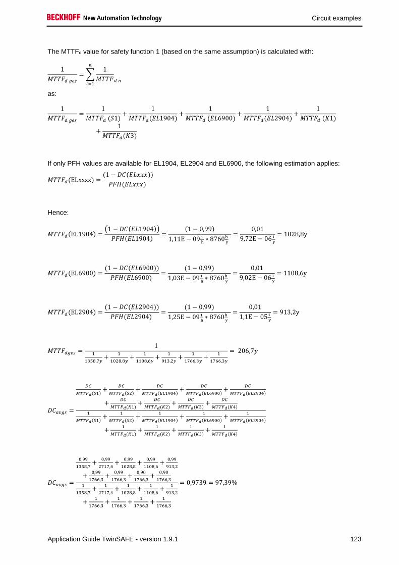
Circuit examples
Application Guide TwinSAFE - version 1.9.1 123
The MTTFd value for safety function 1 (based on the same assumption) is calculated with:
1
𝑀𝑇𝑇𝐹𝑑 𝑔𝑒𝑠
= ∑1
𝑀𝑇𝑇𝐹𝑑 𝑛
𝑛
𝑖=1
as:
1
𝑀𝑇𝑇𝐹𝑑 𝑔𝑒𝑠
=1
𝑀𝑇𝑇𝐹𝑑 (𝑆1)+
1
𝑀𝑇𝑇𝐹𝑑(𝐸𝐿1904)+
1
𝑀𝑇𝑇𝐹𝑑 (𝐸𝐿6900)+
1
𝑀𝑇𝑇𝐹𝑑(𝐸𝐿2904)+
1
𝑀𝑇𝑇𝐹𝑑 (𝐾1)
+1
𝑀𝑇𝑇𝐹𝑑(𝐾3)
If only PFH values are available for EL1904, EL2904 and EL6900, the following estimation applies:
𝑀𝑇𝑇𝐹𝑑(ELxxxx) =(1 − 𝐷𝐶(𝐸𝐿𝑥𝑥𝑥))
𝑃𝐹𝐻(𝐸𝐿𝑥𝑥𝑥)
Hence:
𝑀𝑇𝑇𝐹𝑑(EL1904) =(1 − 𝐷𝐶(𝐸𝐿1904))
𝑃𝐹𝐻(𝐸𝐿1904)=
(1 − 0,99)
1,11E − 09 1
h∗ 8760h
y
=0,01
9,72E − 061
y
= 1028,8y
𝑀𝑇𝑇𝐹𝑑(EL6900) =(1 − 𝐷𝐶(𝐸𝐿6900))
𝑃𝐹𝐻(𝐸𝐿6900) =
(1 − 0,99)
1,03E − 091
h∗ 8760h
y
=0,01
9,02E − 061
y
= 1108,6y
𝑀𝑇𝑇𝐹𝑑(EL2904) =(1 − 𝐷𝐶(𝐸𝐿2904))
𝑃𝐹𝐻(𝐸𝐿2904) =
(1 − 0,99)
1,25E − 091
h∗ 8760h
y
=0,01
1,1E − 051
y
= 913,2y
𝑀𝑇𝑇𝐹𝑑𝑔𝑒𝑠 =1
1
1358,7𝑦+
1
1028,8𝑦+
1
1108,6𝑦+
1
913,2𝑦+
1
1766,3𝑦+
1
1766,3𝑦
= 206,7𝑦
𝐷𝐶𝑎𝑣𝑔𝑠 =
𝐷𝐶
𝑀𝑇𝑇𝐹𝑑(𝑆1)+
𝐷𝐶
𝑀𝑇𝑇𝐹𝑑(𝑆2)+
𝐷𝐶
𝑀𝑇𝑇𝐹𝑑(𝐸𝐿1904)+
𝐷𝐶
𝑀𝑇𝑇𝐹𝑑(𝐸𝐿6900)+
𝐷𝐶
𝑀𝑇𝑇𝐹𝑑(𝐸𝐿2904)
+𝐷𝐶
𝑀𝑇𝑇𝐹𝑑(𝐾1)+
𝐷𝐶
𝑀𝑇𝑇𝐹𝑑(𝐾2)+
𝐷𝐶
𝑀𝑇𝑇𝐹𝑑(𝐾3)+
𝐷𝐶
𝑀𝑇𝑇𝐹𝑑(𝐾4)
1
𝑀𝑇𝑇𝐹𝑑(𝑆1)+
1
𝑀𝑇𝑇𝐹𝑑(𝑆2)+
1
𝑀𝑇𝑇𝐹𝑑(𝐸𝐿1904)+
1
𝑀𝑇𝑇𝐹𝑑(𝐸𝐿6900)+
1
𝑀𝑇𝑇𝐹𝑑(𝐸𝐿2904)
+1
𝑀𝑇𝑇𝐹𝑑(𝐾1)+
1
𝑀𝑇𝑇𝐹𝑑(𝐾2)+
1
𝑀𝑇𝑇𝐹𝑑(𝐾3)+
1
𝑀𝑇𝑇𝐹𝑑(𝐾4)
𝐷𝐶𝑎𝑣𝑔𝑠 =
0,99
1358,7+
0,99
2717,4+
0,99
1028,8+
0,99
1108,6+
0,99
913,2
+0,99
1766,3+
0,99
1766,3+
0,90
1766,3+
0,90
1766,31
1358,7+
1
2717,4+
1
1028,8+
1
1108,6+
1
913,2
+1
1766,3+
1
1766,3+
1
1766,3+
1
1766,3
= 0,9739 = 97,39%

Circuit examples
124 Application Guide TwinSAFE - version 1.9.1
Note
Category
This structure is possible up to category 4 at the most.
MTTFd Designation for each channel Range for each channel
low 3 years ≤ MTTFd < 10 years
medium 10 years ≤ MTTFd < 30 years
high 30 years ≤ MTTFd ≤ 100 years
DCavg Designation Range
none DC < 60 %
low 60 % ≤ DC < 90 %
medium 90 % ≤ DC < 99 %
high 99 % ≤ DC
For practical usability, the number of the ranges was limited to four. An accuracy of 5% is assumed for
the limit values shown in this table.
Category B 1 2 2 3 3 4
DC MTTFd
none none low medium low medium high
low a - a b b c -
medium b - b c c d -
high - c c d d d e
Safety integrity level according to Tab. 3 EN62061 Safety integrity level Probability of a dangerous failure per hour
(PFHD)
3 ≥ 10-8 to < 10-7
2 (*) ≥ 10-7 to < 10-6
1 ≥ 10-6 to < 10-5
(*) In accordance with EN62061 chapter 6.7.7.2, SILCL in restricted to a maximum of SIL2 in relation to
structural constraints for a subsystem that has an HFT of 0 and for which fault exclusions have been
applied to faults that could lead to a dangerous failure.

Circuit examples
Application Guide TwinSAFE - version 1.9.1 125
2.19 Networked system (Category 4, PL e)
2 plants are connected via Ethernet here. The path can also be implemented by a Wireless Ethernet
connection. Each station switches the outputs K1 / K2 on only if the second machine does not signal an
emergency stop. The signals from the emergency stop button, the restart and the feedback loop are wired
to safe inputs. The output of the ESTOP block is linked to an AND function block and additionally signaled
to the respective other machine via the network. The ESTOP output of the respective other machine is
linked to the AND function block and the output of the AND gate then switches the contactors on the safe
output terminal.
Testing and checking for discrepancy are activated for the input signals. The testing of the outputs is also
active.
RT
Eth
ern
et o
r Wire
less
Eth
ern
et
K1 K2
Machine 1 Machine 2
Logical link
Emergency
stop button
Restart K1
K2
K1 K2
Logical link
Emergency
stop button
Restart K1
K2
S2
S1
S2
S1
Note
Start / restart
If the result of the risk and hazard analysis shows that a contactor check is necessary
when switching the contactors of the respective remote controller, this is to be done
using an EDM function block.

Circuit examples
126 Application Guide TwinSAFE - version 1.9.1
Note
Contactor monitoring
If the result of the risk and hazard analysis shows that a contactor check is necessary
when switching the contactors of the respective remote controller, this is to be done
using an EDM function block.
2.19.1 Parameters of the safe input and output terminals
EL1904 (applies to all EL1904 used)
Parameter Value
Sensor test channel 1 active Yes
Sensor test channel 2 active Yes
Sensor test channel 3 active Yes
Sensor test channel 4 active Yes
Logic channel 1 and 2 Single Logic
Logic channel 3 and 4 Single Logic
EL2904
Parameter Value
Current measurement active Yes
Output test pulses active Yes
2.19.2 Block formation and safety loops
2.19.2.1 Safety function 1
S1
(1)
EL1904
(1)
EL6900
(1)
EL2904
(1)
K1
(1)
K2
(1)
S2
(1)
Safety over
EtherCAT
EL1904
(2)
EL6900
(2)
S1
(2)

Circuit examples
Application Guide TwinSAFE - version 1.9.1 127
2.19.3 Calculation
2.19.3.1 PFH / MTTFd /B10d – values
Component Value
EL1904 – PFH 1.11E-09
EL2904 – PFH 1.25E-09
EL6900 – PFH 1.03E-09
Safety over EtherCAT (FSoE) 1.00E-09
S1 – B10d 1,000,000
S2 – B10d 2,000,000
K1 – B10d 1,300,000
K2 – B10d 1,300,000
Days of operation (dop) 230
Hours of operation / day (hop) 8
Cycle time (minutes) (TZyklus) 15 (4x per hour)
Lifetime (T1) 20 years = 175200 hours
2.19.3.2 Diagnostic Coverage DC
Component Value
S1 with testing/plausibility DCavg=99%
S2 with plausibility DCavg=90%
K1/K2 with testing and EDM
(actuation 1x per shift)
DCavg=99%
2.19.3.3 Calculation for safety function 1
Calculation of the PFH and MTTFd values from the B10d values:
From:
𝑛𝑜𝑝 =𝑑𝑜𝑝∗ℎ𝑜𝑝∗60
𝑇𝑍𝑦𝑘𝑙𝑢𝑠
and:
𝑀𝑇𝑇𝐹𝑑 =𝐵10𝑑
0,1 ∗ 𝑛𝑜𝑝
Inserting the values, this produces:
S1:
𝑛𝑜𝑝 =230∗8∗60
15= 7360
𝑀𝑇𝑇𝐹𝑑 =1000000
0,1∗7360= 1358,7y = 11902212h

Circuit examples
128 Application Guide TwinSAFE - version 1.9.1
S2:
𝑛𝑜𝑝 =230∗8∗60
15= 7360
𝑀𝑇𝑇𝐹𝑑 =2000000
0,1∗7360= 2717,4y = 23804424h
K1/K2:
𝑛𝑜𝑝 =230∗8∗60
15= 7360
𝑀𝑇𝑇𝐹𝑑 =1300000
0,1 ∗ 7360= 1766,3y = 15472788h
and the assumption that S1, S2, K1 and K2 are each single-channel:
𝑀𝑇𝑇𝐹𝑑 =1
𝜆𝑑
produces for
𝑃𝐹𝐻 =0,1 ∗ 𝑛𝑜𝑝 ∗ (1 − 𝐷𝐶)
𝐵10𝑑=
1 − DC
MTTFd
S1:
𝑃𝐹𝐻 =1 − 0,99
1358,7 ∗ 8760= 8,40E − 10
S2:
𝑃𝐹𝐻 =1 − 0,90
2717,4 ∗ 8760= 4,20E − 09
K1/K2: actuation 1x per shift and direct feedback
𝑃𝐹𝐻 =1 − 0,99
1766,3 ∗ 8760= 6,46E − 10
The following assumptions must now be made:
Safety switch S1: According to BIA report 2/2008, error exclusion to up 100000 cycles is possible,
provided the manufacturer has confirmed this. If no confirmation exists, S1 is included in the calculation
as follows.
Relays K1 and K2 are both connected to the safety function. The non-functioning of a relay does not lead
to a dangerous situation, but it is discovered by the feedback. Furthermore, the B10d values for K1 and
K2 are identical.
There is a coupling coefficient between the components that are connected via two channels. Examples
are temperature, EMC, voltage peaks or signals between these components. This is assumed to be the
worst-case estimation, where ß =10%. EN 62061 contains a table with which this ß-factor can be
precisely determined. Further, it is assumed that all usual measures have been taken to prevent both
channels failing unsafely at the same time due to an error (e.g. overcurrent through relay contacts,
overtemperature in the control cabinet).

Circuit examples
Application Guide TwinSAFE - version 1.9.1 129
This produces for the calculation of the PFH value for safety function 1:
𝑃𝐹𝐻𝑔𝑒𝑠 = 𝑃𝐹𝐻(𝑆1) + 𝛽 ∗𝑃𝐹𝐻(𝐾1) + 𝑃𝐹𝐻(𝐾2)
2+ (1 − 𝛽)2 ∗ (𝑃𝐹𝐻(𝐾1) ∗ 𝑃𝐹𝐻(𝐾2)) ∗ 𝑇1 + 𝑃𝐹𝐻(𝑆2) + 𝑃𝐹𝐻(𝐸𝐿1904)
+ 𝑃𝐹𝐻(𝐸𝐿6900) + 𝑃𝐹𝐻(𝐸𝐿2904) + 𝑃𝐹𝐻(𝐹𝑆𝑜𝐸) + 𝑃𝐹𝐻(𝑆1) + 𝑃𝐹𝐻(𝐸𝐿1904) + 𝑃𝐹𝐻(𝐸𝐿6900)
Since the portion (1 − 𝛽)2 ∗ (𝑃𝐹𝐻(𝐾1) ∗ 𝑃𝐹𝐻(𝐾2)) ∗ 𝑇1 is smaller than the rest by the power of ten, it is
neglected in this and all further calculations for the purpose of simplification.
to:
𝑃𝐹𝐻𝑔𝑒𝑠 = 8,40𝐸 − 10 + 10% ∗6,46𝐸 − 10 + 6,46𝐸 − 10
2+ 4,20𝐸 − 09 + 1,11𝐸 − 09 + 1,03𝐸 − 09 + 1,25𝐸
− 09 + 1,00𝐸 − 9 + 8,40𝐸 − 10 + 1,11𝐸 − 09 + 1,03𝐸 − 09 = 𝟏, 𝟐𝟓𝑬 − 𝟎𝟖
The MTTFd value for safety function 1 (based on the same assumption) is calculated with:
1
𝑀𝑇𝑇𝐹𝑑 𝑔𝑒𝑠
= ∑1
𝑀𝑇𝑇𝐹𝑑 𝑛
𝑛
𝑖=1
as:
1
𝑀𝑇𝑇𝐹𝑑 𝑔𝑒𝑠
=1
𝑀𝑇𝑇𝐹𝑑 (𝑆1)+
1
𝑀𝑇𝑇𝐹𝑑 (𝐾1)+
1
𝑀𝑇𝑇𝐹𝑑 (𝑆2)+
1
𝑀𝑇𝑇𝐹𝑑(𝐸𝐿1904)+
1
𝑀𝑇𝑇𝐹𝑑 (𝐸𝐿6900)
+1
𝑀𝑇𝑇𝐹𝑑(𝐸𝐿2904)+
1
𝑀𝑇𝑇𝐹𝑑 (𝐹𝑆𝑜𝐸)+
1
𝑀𝑇𝑇𝐹𝑑 (𝑆1)+
1
𝑀𝑇𝑇𝐹𝑑 (𝐸𝐿1904)+
1
𝑀𝑇𝑇𝐹𝑑 (𝐸𝐿6900)
with:
𝑀𝑇𝑇𝐹𝑑(S1) =𝐵10𝑑(𝑆1)
0,1 ∗ 𝑛𝑜𝑝
𝑀𝑇𝑇𝐹𝑑(S2) =𝐵10𝑑(𝑆2)
0,1 ∗ 𝑛𝑜𝑝
𝑀𝑇𝑇𝐹𝑑(K1) =𝐵10𝑑(𝐾1)
0,1 ∗ 𝑛𝑜𝑝
If only PFH values are available for EL1904, EL2904 and EL6900, the following estimation applies:
𝑀𝑇𝑇𝐹𝑑(ELxxxx) =(1 − 𝐷𝐶(𝐸𝐿𝑥𝑥𝑥))
𝑃𝐹𝐻(𝐸𝐿𝑥𝑥𝑥)
Hence:
𝑀𝑇𝑇𝐹𝑑(EL1904) =(1 − 𝐷𝐶(𝐸𝐿1904))
𝑃𝐹𝐻(𝐸𝐿1904)=
(1 − 0,99)
1,11E − 09 1
h∗ 8760h
y
=0,01
9,72E − 061
y
= 1028,8y
𝑀𝑇𝑇𝐹𝑑(EL6900) =(1 − 𝐷𝐶(𝐸𝐿6900))
𝑃𝐹𝐻(𝐸𝐿6900) =
(1 − 0,99)
1,03E − 091
h∗ 8760h
y
=0,01
9,02E − 061
y
= 1108,6y

Circuit examples
130 Application Guide TwinSAFE - version 1.9.1
𝑀𝑇𝑇𝐹𝑑(EL2904) =(1 − 𝐷𝐶(𝐸𝐿2904))
𝑃𝐹𝐻(𝐸𝐿2904) =
(1 − 0,99)
1,25E − 091
h∗ 8760h
y
=0,01
1,1E − 051
y
= 913,2y
𝑀𝑇𝑇𝐹𝑑(FSoE) =(1 − 𝐷𝐶(𝐹𝑆𝑜𝐸))
𝑃𝐹𝐻(𝐹𝑆𝑜𝐸) =
(1 − 0,99)
1,00E − 09 1
h∗ 8760h
y
=0,01
8,76E − 061
y
= 1141,6y
𝑀𝑇𝑇𝐹𝐷𝑔𝑒𝑠 =1
1
1358,7y+
1
1766,3y+
1
2717,4𝑦+
1
1028,8𝑦+
1
1108,6𝑦+
1
913,2𝑦+
1
1358,7𝑦+
1
1141,6𝑦+
1
1028,8𝑦+
1
1108,6𝑦
= 123,1𝑦
𝐷𝐶𝑎𝑣𝑔 =
99%
1358,7+
99%
1766,3+
99%
1766,3+
90%
2717,4+
99%
1028,8+
99%
1108,6+
99%
913,2+
99%
1358,7+
99%
1141,6+
99%
1028,8+
99%
1108,61
1358,7+
1
1766,3+
1
1766,3+
1
2717,4+
1
1028,8+
1
1108,6+
1
913,2+
1
1358,7+
1
1141,6+
1
1028,8+
1
1108,6
= 98,99%
Note
Category
This structure is possible up to category 4 at the most.
MTTFd Designation for each channel Range for each channel
low 3 years ≤ MTTFd < 10 years
medium 10 years ≤ MTTFd < 30 years
high 30 years ≤ MTTFd ≤ 100 years
DCavg Designation Range
none DC < 60 %
low 60 % ≤ DC < 90 %
medium 90 % ≤ DC < 99 %
high 99 % ≤ DC
For practical usability, the number of the ranges was limited to four. An accuracy of 5% is assumed for
the limit values shown in this table.
Category B 1 2 2 3 3 4
DC MTTFd
none none low medium low medium high
low a - a b b c -
medium b - b c c d -
high - c c d d d e

Circuit examples
Application Guide TwinSAFE - version 1.9.1 131
2.20 Drive option AX5801 with SS1 stop function (Category 4, PL e)
By activating the emergency stop button inputs EStopIn1 and EStopIn2 of FB ESTOP are switched to
state “0”, resulting in outputs EStopOut and EStopDelOut of FB ESTOP being switched to state “0”. As a
result, a quick stop command is issued to the PLC and therefore the AX5000 via EtherCAT. The output
EStopDelOut of the ESTOP FB ensures that, after the expiry of a specified delay time (in this case e.g.
1000 ms), the 24 V supply of the safety option AX5801 is interrupted and the internal relays of the
AX5801 are thus de-energized. The two channels (motors) are switched torque-free via the internal
switch-off paths of the AX5000.
Testing and checking for discrepancy are activated for the input signals. The testing of the outputs is also
active. The relays of the 4 AX5801 option cards are wired in parallel to a safe output of the EL2904. The
feedback loops are wired in series to a safe input. The restart signal is wired to a non-safe input.
Restart
Emergency stop
button
Logical connection
PLC / NC
1
2
3
4
5
6
1
2
3
4
1
2
3
4
5
6
1
2
3
4
1
2
3
4
5
6
1
2
3
4
1
2
3
4
5
6
1
2
3
4
AX5801 AX5801 AX5801 AX5801
AX5000AX5000AX5000AX5000
Feedback loop
S1
S2
EDM

Circuit examples
132 Application Guide TwinSAFE - version 1.9.1
2.20.1 Parameters of the safe input and output terminals
EL1904 (applies to all EL1904 used)
Parameter Value
Sensor test channel 1 active Yes
Sensor test channel 2 active Yes
Sensor test channel 3 active Yes
Sensor test channel 4 active Yes
Logic channel 1 and 2 Single Logic
Logic channel 3 and 4 Single Logic
EL2904
Parameter Value
Current measurement active Yes
Output test pulses active Yes
2.20.2 Block formation and safety loops
2.20.2.1 Safety function 1
2.20.3 Calculation
2.20.3.1 PFH / MTTFd /B10d – values
Component Value
EL1904 – PFH 1.11E-09
EL2904 – PFH 1.25E-09
EL6900 – PFH 1.03E-09
AX5801 – B10d 780,000
S1 – B10d 100,000
Days of operation (dop) 230
Hours of operation / day (hop) 8
Cycle time (minutes) (TZyklus) 60 (1x per hour)
Lifetime (T1) 20 years = 175200 hours
EL1904 EL6900 EL1904 EL6900 S1
EL2904 AX5801 EL2904 AX5801 EL2904 AX5801 EL2904 AX5801
EL2904
EL2904 AX5801 EL2904 AX5801 EL2904 AX5801 EL2904 AX5801

Circuit examples
Application Guide TwinSAFE - version 1.9.1 133
2.20.3.2 Diagnostic Coverage DC
Component Value
S1 with testing/plausibility DCavg=99%
AX5801 DCavg=99%
2.20.3.3 Calculation for safety function 1
Calculation of the PFH and MTTFd values from the B10d values:
From:
𝑛𝑜𝑝 =𝑑𝑜𝑝∗ℎ𝑜𝑝∗60
𝑇𝑍𝑦𝑘𝑙𝑢𝑠
and:
𝑀𝑇𝑇𝐹𝑑 =𝐵10𝑑
0,1 ∗ 𝑛𝑜𝑝
Inserting the values, this produces:
S1:
𝑛𝑜𝑝 =230∗8∗60
60= 1840
𝑀𝑇𝑇𝐹𝑑 =100000
0,1∗1840= 543,5y = 4761060h
AX5801:
𝑛𝑜𝑝 =230∗8∗60
60= 1840
𝑀𝑇𝑇𝐹𝑑 =780000
0,1 ∗ 1840= 4239,1y = 37134516h
𝑇10𝐷 =𝐵10𝐷
𝑛𝑜𝑝=
780000
18401
𝑦
= 423 𝑦
and the assumption that S1 is single-channel:
𝑀𝑇𝑇𝐹𝑑 =1
𝜆𝑑
produces for
𝑃𝐹𝐻 =0,1 ∗ 𝑛𝑜𝑝 ∗ (1 − 𝐷𝐶)
𝐵10𝑑=
1 − DC
MTTFd
S1:
𝑃𝐹𝐻 =1 − 0,99
543,5 ∗ 8760= 2,10E − 9

Circuit examples
134 Application Guide TwinSAFE - version 1.9.1
AX5801:
𝑃𝐹𝐻 =1 − 0,99
4239,1 ∗ 8760= 2,70E − 10
The following assumptions must now be made:
Safety switch S1: According to BIA report 2/2008, error exclusion to up 100,000 cycles is possible, provided
the manufacturer has confirmed this. If no confirmation exists, S1 is included in the calculation as follows.
There is a coupling coefficient between the components that are connected via two channels. Examples
are temperature, EMC, voltage peaks or signals between these components. This is assumed to be the
worst-case estimation, where ß =10%. EN 62061 contains a table with which this ß-factor can be
precisely determined. Further, it is assumed that all usual measures have been taken to prevent both
channels failing unsafely at the same time due to an error (e.g. overcurrent through relay contacts,
overtemperature in the control cabinet).
This produces for the calculation of the PFH value for safety function 1:
𝑃𝐹𝐻𝑔𝑒𝑠 = 𝑃𝐹𝐻(𝑆1) + 𝑃𝐹𝐻(𝐸𝐿1904) + 𝑃𝐹𝐻(𝐸𝐿6900) + 𝑃𝐹𝐻(𝐸𝐿2904) + 𝛽 ∗4 ∗ 𝑃𝐹𝐻(𝐴𝑋5801) + 4 ∗ 𝑃𝐹𝐻(𝐴𝑋5801)
2+ 4 ∗ (1 − 𝛽)2 ∗ (𝑃𝐹𝐻(𝐴𝑋5801) ∗ 𝑃𝐹𝐻(𝐴𝑋5801)) ∗ 𝑇1
Since the portions (1 − 𝛽)2 ∗ (𝑃𝐹𝐻(𝑥) ∗ 𝑃𝐹𝐻(𝑦)) ∗ 𝑇1 are smaller than the rest by the power of ten, they are
neglected in this and all further calculations for the purpose of simplification.
to:
𝑃𝐹𝐻𝑔𝑒𝑠 = 2,10𝐸 − 09 + 1,11𝐸 − 09 + 1,03𝐸 − 09 + 1,25𝐸 − 09 + 10% ∗4 ∗ 2,70𝐸 − 10 + 4 ∗ 2,70𝐸 − 10
2= 𝟓, 𝟔𝟎𝑬 − 𝟎𝟗
The MTTFd value for safety function 1 (based on the same assumption) is calculated with:
1
𝑀𝑇𝑇𝐹𝑑 𝑔𝑒𝑠
= ∑1
𝑀𝑇𝑇𝐹𝑑 𝑛
𝑛
𝑖=1
as:
1
𝑀𝑇𝑇𝐹𝑑 𝑔𝑒𝑠
=1
𝑀𝑇𝑇𝐹𝑑 (𝑆1)+
1
𝑀𝑇𝑇𝐹𝑑 (𝐸𝐿1904)+
1
𝑀𝑇𝑇𝐹𝑑 (𝐸𝐿6900)+
1
𝑀𝑇𝑇𝐹𝑑(𝐸𝐿2904)+
1
𝑀𝑇𝑇𝐹𝑑 (𝐴𝑋5801)
+1
𝑀𝑇𝑇𝐹𝑑(𝐴𝑋5801)+
1
𝑀𝑇𝑇𝐹𝑑 (𝐴𝑋5801)+
1
𝑀𝑇𝑇𝐹𝑑 (𝐴𝑋5801)
with:
𝑀𝑇𝑇𝐹𝑑(S1) =𝐵10𝑑(𝑆1)
0,1 ∗ 𝑛𝑜𝑝
𝑀𝑇𝑇𝐹𝑑(AX5801) =𝐵10𝑑(𝐴𝑋5801)
0,1 ∗ 𝑛𝑜𝑝

Circuit examples
Application Guide TwinSAFE - version 1.9.1 135
If only PFH values are available for EL1904, EL2904 and EL6900, the following estimation applies:
𝑀𝑇𝑇𝐹𝑑(ELxxxx) =(1 − 𝐷𝐶(𝐸𝐿𝑥𝑥𝑥))
𝑃𝐹𝐻(𝐸𝐿𝑥𝑥𝑥)
Hence:
𝑀𝑇𝑇𝐹𝑑(EL1904) =(1 − 𝐷𝐶(𝐸𝐿1904))
𝑃𝐹𝐻(𝐸𝐿1904)=
(1 − 0,99)
1,11E − 09 1
h∗ 8760h
y
=0,01
9,72E − 061
y
= 1028,8y
𝑀𝑇𝑇𝐹𝑑(EL6900) =(1 − 𝐷𝐶(𝐸𝐿6900))
𝑃𝐹𝐻(𝐸𝐿6900) =
(1 − 0,99)
1,03E − 091
h∗ 8760h
y
=0,01
9,02E − 061
y
= 1108,6y
𝑀𝑇𝑇𝐹𝑑(EL2904) =(1 − 𝐷𝐶(𝐸𝐿2904))
𝑃𝐹𝐻(𝐸𝐿2904) =
(1 − 0,99)
1,25E − 091
h∗ 8760h
y
=0,01
1,1E − 051
y
= 913,2y
𝑀𝑇𝑇𝐹𝐷𝑔𝑒𝑠 =1
1
543,5𝑦+
1
1028,8𝑦+
1
1108,6𝑦+
1
913,2𝑦+
1
4239,1𝑦+
1
4239,1𝑦+
1
4239,1𝑦+
1
4239,1𝑦
= 173,8𝑦
𝐷𝐶𝑎𝑣𝑔 =99%
543,5+
99%
1028,8+
99%
1108,6+
99%
913,2+
99%
4239,1+
99%
4239,1+
99%
4239,1+
99%
4239,1+
99%
4239,1+
99%
4239,1+
99%
4239,1+
99%
4239,11
543,5+
1
1028,8+
1
1108,6+
1
913,2+
1
4239,1+
1
4239,1+
1
4239,1+
1
4239,1+
1
4239,1+
1
4239,1+
1
4239,1+
1
4239,1
= 99,0%

Circuit examples
136 Application Guide TwinSAFE - version 1.9.1
Note
Category
This structure is possible up to category 4 at the most.
CAUTION
Implement a restart lock in the machine!
The restart lock is NOT part of the safety chain and must be implemented in the machine!
MTTFd Designation for each channel Range for each channel
low 3 years ≤ MTTFd < 10 years
medium 10 years ≤ MTTFd < 30 years
high 30 years ≤ MTTFd ≤ 100 years
DCavg Designation Range
none DC < 60 %
low 60 % ≤ DC < 90 %
medium 90 % ≤ DC < 99 %
high 99 % ≤ DC
Category B 1 2 2 3 3 4
DC MTTFd
none none low medium low medium high
low a - a b b c -
medium b - b c c d -
high - c c d d d e

Circuit examples
Application Guide TwinSAFE - version 1.9.1 137
2.21 Drive option AX5805 with SS2 stop function (Category 4, PL e)
The protective door is connected with a combination of normally closed and normally open contacts to an
EL1904 safe input terminal. Testing and checking for discrepancy are activated for the input signals. The
output is linked on the AX5805.
The feedback signals are checked via the control and status word returned by the drive option.
AX5805 AX5805 AX5805 AX5805
AX5000AX5000AX5000AX5000
Logical connection in
the EL6900C
on
tro
l / sta
tus w
ord
CLOSED
OPEN
S1
S2
2.21.1 Parameters of the safe input and output terminals
EL1904 (applies to all EL1904 used)
Parameter Value
Sensor test channel 1 active Yes
Sensor test channel 2 active Yes
Sensor test channel 3 active Yes
Sensor test channel 4 active Yes
Logic channel 1 and 2 Single Logic
Logic channel 3 and 4 Single Logic

Circuit examples
138 Application Guide TwinSAFE - version 1.9.1
AX5805
Parameter Value
-
2.21.2 Block formation and safety loops
2.21.2.1 Safety function 1
2.21.3 Calculation
2.21.3.1 PFH / MTTFd /B10d – values
Component Value
EL1904 – PFH 1.11E-09
EL6900 – PFH 1.03E-09
AX5805 – PFH 5.15E-09 (see list of permitted motors)
S1 – B10d 1,000,000
S2 – B10d 2,000,000
Days of operation (dop) 230
Hours of operation / day (hop) 8
Cycle time (minutes) (TZyklus) 60 (1x per hour)
Lifetime (T1) 20 years = 175200 hours
2.21.3.2 Diagnostic Coverage DC
Component Value
S1/S2 with testing/plausibility DCavg=99%
2.21.3.3 Calculation for safety function 1
Calculation of the PFH and MTTFd values from the B10d values:
From:
𝑛𝑜𝑝 =𝑑𝑜𝑝∗ℎ𝑜𝑝∗60
𝑇𝑍𝑦𝑘𝑙𝑢𝑠
and:
𝑀𝑇𝑇𝐹𝑑 =𝐵10𝑑
0,1 ∗ 𝑛𝑜𝑝
EL1904 EL6900 EL2904
S1
S2
AX5805 EL1904 EL6900 AX5805
S1
S2
AX5805 AX5805

Circuit examples
Application Guide TwinSAFE - version 1.9.1 139
Inserting the values, this produces:
S1:
𝑛𝑜𝑝 =230∗8∗60
60= 1840
𝑀𝑇𝑇𝐹𝑑 =1000000
0,1∗1840= 5434,8y = 47608848h
S2:
𝑛𝑜𝑝 =230∗8∗60
60= 1840
𝑀𝑇𝑇𝐹𝑑 =2000000
0,1∗1840= 10869,6y = 95217696h
and the assumption that S1 and S2 are each single-channel:
𝑀𝑇𝑇𝐹𝑑 =1
𝜆𝑑
produces for
𝑃𝐹𝐻 =0,1 ∗ 𝑛𝑜𝑝 ∗ (1 − 𝐷𝐶)
𝐵10𝑑=
1 − DC
MTTFd
S1:
𝑃𝐹𝐻 =1 − 0,99
5434,8 ∗ 8760= 2,10E − 10
S2:
𝑃𝐹𝐻 =1 − 0,99
10869,6 ∗ 8760= 1,05E − 10
The following assumptions must now be made:
The door switches S1/S2 are always actuated in opposite directions. Since the switches have different
values, but the complete protective door switch consists of a combination of normally closed and normally
open contacts and both switches must function, the poorer of the two values (S1) can be taken for the
combination!
There is a coupling coefficient between the components that are connected via two channels. Examples
are temperature, EMC, voltage peaks or signals between these components. This is assumed to be the
worst-case estimation, where ß =10%. EN 62061 contains a table with which this ß-factor can be
precisely determined. Further, it is assumed that all usual measures have been taken to prevent both
channels failing unsafely at the same time due to an error (e.g. overcurrent through relay contacts,
overtemperature in the control cabinet).
This produces for the calculation of the PFH value for safety function 1:
𝑃𝐹𝐻𝑔𝑒𝑠 = 𝛽 ∗𝑃𝐹𝐻(𝑆1) + 𝑃𝐹𝐻(𝑆2)
2+ (1 − 𝛽)2 ∗ (𝑃𝐹𝐻(𝑆1) ∗ 𝑃𝐹𝐻(𝑆2)) ∗ 𝑇1 + 𝑃𝐹𝐻(𝐸𝐿1904) + 𝑃𝐹𝐻(𝐸𝐿6900)
+ 𝑃𝐹𝐻(𝐴𝑋5805) + 𝑃𝐹𝐻(𝐴𝑋5805) + 𝑃𝐹𝐻(𝐴𝑋5805) + 𝑃𝐹𝐻(𝐴𝑋5805)
Since the portions (1 − 𝛽)2 ∗ (𝑃𝐹𝐻(𝑥) ∗ 𝑃𝐹𝐻(𝑦)) ∗ 𝑇1 are smaller than the rest by the power of ten, they are
neglected in this and all further calculations for the purpose of simplification.
to:

Circuit examples
140 Application Guide TwinSAFE - version 1.9.1
𝑃𝐹𝐻𝑔𝑒𝑠 = 10% ∗2,10𝐸 − 10 + 1,05𝐸 − 10
2+ 1,11𝐸 − 09 + 1,03𝐸 − 09 + 4 ∗ (5,15𝐸 − 09) = 𝟐, 𝟐𝟖𝑬 − 𝟎𝟖
The MTTFd value for safety function 1 (based on the same assumption) is calculated with:
1
𝑀𝑇𝑇𝐹𝑑 𝑔𝑒𝑠
= ∑1
𝑀𝑇𝑇𝐹𝑑 𝑛
𝑛
𝑖=1
as:
1
𝑀𝑇𝑇𝐹𝑑 𝑔𝑒𝑠
=1
𝑀𝑇𝑇𝐹𝑑 (𝑆1)+
1
𝑀𝑇𝑇𝐹𝑑 (𝐸𝐿1904)+
1
𝑀𝑇𝑇𝐹𝑑 (𝐸𝐿6900)+
1
𝑀𝑇𝑇𝐹𝑑 (𝐴𝑋5805)+
1
𝑀𝑇𝑇𝐹𝑑(𝐴𝑋5805)
+1
𝑀𝑇𝑇𝐹𝑑 (𝐴𝑋5805)+
1
𝑀𝑇𝑇𝐹𝑑 (𝐴𝑋5805)
with:
𝑀𝑇𝑇𝐹𝑑(S1) =𝐵10𝑑(𝑆1)
0,1 ∗ 𝑛𝑜𝑝
𝑀𝑇𝑇𝐹𝑑(S2) =𝐵10𝑑(𝑆2)
0,1 ∗ 𝑛𝑜𝑝
If only PFH values are available for EL1904, AX5805 and EL6900, the following estimation applies:
𝑀𝑇𝑇𝐹𝑑(ELxxxx) =(1 − 𝐷𝐶(𝐸𝐿𝑥𝑥𝑥))
𝑃𝐹𝐻(𝐸𝐿𝑥𝑥𝑥)
Hence:
𝑀𝑇𝑇𝐹𝑑(EL1904) =(1 − 𝐷𝐶(𝐸𝐿1904))
𝑃𝐹𝐻(𝐸𝐿1904)=
(1 − 0,99)
1,11E − 09 1
h∗ 8760h
y
=0,01
9,72E − 061
y
= 1028,8y
𝑀𝑇𝑇𝐹𝑑(EL6900) =(1 − 𝐷𝐶(𝐸𝐿6900))
𝑃𝐹𝐻(𝐸𝐿6900) =
(1 − 0,99)
1,03E − 091
h∗ 8760h
y
=0,01
9,02E − 061
y
= 1108,6y
𝑀𝑇𝑇𝐹𝑑(AX5805) =(1 − 𝐷𝐶(AX5805))
𝑃𝐹𝐻(AX5805) =
(1 − 0,99)
5,15E − 091
h∗ 8760h
y
=0,01
4,51E − 051
y
= 221,7y

Circuit examples
Application Guide TwinSAFE - version 1.9.1 141
𝑀𝑇𝑇𝐹𝐷𝑔𝑒𝑠 =1
1
5434,8𝑦+
1
1028,8𝑦+
1
1108,6𝑦+
1
221,7𝑦+
1
221,7𝑦+
1
221,7𝑦+
1
221,7𝑦
= 49,8𝑦
𝐷𝐶𝑎𝑣𝑔 =
99%
5434,8+
99%
10869,6+
99%
1028,8+
99%
1108,6+
99%
221,7+
99%
221,7+
99%
221,7+
99%
221,71
5434,8+
1
10869,6+
1
1028,8+
1
1108,6+
1
221,7+
1
221,7+
1
221,7+
1
221,7
= 99,0%
Note
Category
This structure is possible up to category 4 at the most.
MTTFd Designation for each channel Range for each channel
low 3 years ≤ MTTFd < 10 years
medium 10 years ≤ MTTFd < 30 years
high 30 years ≤ MTTFd ≤ 100 years
DCavg Designation Range
none DC < 60 %
low 60 % ≤ DC < 90 %
medium 90 % ≤ DC < 99 %
high 99 % ≤ DC
Category B 1 2 2 3 3 4
DC MTTFd
none none low medium low medium high
low a - a b b c -
medium b - b c c d -
high - c c d d d e

Circuit examples
142 Application Guide TwinSAFE - version 1.9.1
2.22 Direct wiring of the TwinSAFE outputs to TwinSAFE inputs (single-channel) (Category 2, PL c)
The output of an EL2904 is wired directly to a safe input of an EL1904; the test pulses and current
measurement of the outputs and the sensor test of the inputs are thereby deactivated. Hence, cyclic
checks for cross-circuit and external feed on the cable are not possible.
On account of their high internal diagnostics, the EL2904 and EL1904 are to be evaluated as individual
components with Category 2, SIL2 and PL d, since only a single-channel structure is used externally. The
total performance level of output and input is to be evaluated with PL c at the most on account of chapter
6.2.5 DIN EN ISO 13849-1:2016-06.
The test setup required for Category 2 is integrated in the EL2904. When switching on the output of the
EL2904, a check is performed to ascertain whether 24 V are actually read back. When switching off, a
check is performed to ascertain whether 0 V are actually read back. If an error is detected, the EL2904
enters the error state, which is also signaled to the higher level safety controller. This module error of the
EL2904 must be evaluated in the machine controller. To do this the parameter ModuleFault is ComError
is to be switched on for the connection to the EL2904, as a result of which the TwinSAFE group switches
to the safe state and signals a ComError in the event of a module error.
EL2904 EL1904
Cat.2, PL c
2.22.1 Parameters of the safe input and output terminals
EL1904
Parameter Value
Sensor test channel 1 active No
Sensor test channel 2 active No
Sensor test channel 3 active No
Sensor test channel 4 active No
Logic channel 1 and 2 Single Logic
Logic channel 3 and 4 Single Logic

Circuit examples
Application Guide TwinSAFE - version 1.9.1 143
EL2904
Parameter Value
Current measurement active No
Output test pulses active No
2.22.2 Block formation and safety loops
2.22.2.1 Safety function 1
2.22.3 Calculation
2.22.3.1 PFH / MTTFd /B10d – values
Component Value
EL1904 – PFH 1.11E-09
EL2904 – PFH 1.25E-09
Days of operation (dop) 230
Hours of operation / day (hop) 8
Cycle time (minutes) (TZyklus) 60 (1x per hour)
Lifetime (T1) 20 years = 175200 hours
2.22.3.2 Diagnostic Coverage DC
Component Value
EL1904/EL2904
On account of the internal diagnostics of the
terminals (such as monitoring of the field voltage,
temperature, etc.) and the checking of the
EL2904 for the correctness of the switched
output each time the signal state changes
DCavg=60%
2.22.3.3 Calculation for safety function 1
This produces for the calculation of the PFH value for safety function 1:
𝑃𝐹𝐻𝑔𝑒𝑠 = 𝑃𝐹𝐻(𝐸𝐿1904) + 𝑃𝐹𝐻(𝐸𝐿2904)
to:
𝑃𝐹𝐻𝑔𝑒𝑠 = 1,11𝐸 − 09 + 1,25𝐸 − 09 = 𝟐, 𝟑𝟔𝑬 − 𝟎𝟗
EL6900 EL2904 EL2904 EL1904

Circuit examples
144 Application Guide TwinSAFE - version 1.9.1
The MTTFd value for safety function 1 (based on the same assumption) is calculated with:
1
𝑀𝑇𝑇𝐹𝑑 𝑔𝑒𝑠
= ∑1
𝑀𝑇𝑇𝐹𝑑 𝑛
𝑛
𝑖=1
as:
1
𝑀𝑇𝑇𝐹𝑑 𝑔𝑒𝑠
=1
𝑀𝑇𝑇𝐹 𝑑(𝐸𝐿1904)+
1
𝑀𝑇𝑇𝐹 𝑑(𝐸𝐿2904)
If only PFH values are available for EL1904 and EL2904, the following estimation applies:
𝑀𝑇𝑇𝐹𝑑(ELxxxx) =(1 − 𝐷𝐶(𝐸𝐿𝑥𝑥𝑥))
𝑃𝐹𝐻(𝐸𝐿𝑥𝑥𝑥)
Hence:
𝑀𝑇𝑇𝐹𝑑(EL1904) =(1 − 𝐷𝐶(𝐸𝐿1904))
𝑃𝐹𝐻(𝐸𝐿1904)=
(1 − 0,60)
1,11E − 09 1
h∗ 8760h
y
=0,4
9,72E − 061
y
= 41152 y
𝑀𝑇𝑇𝐹𝑑(EL2904) =(1 − 𝐷𝐶(𝐸𝐿2904))
𝑃𝐹𝐻(𝐸𝐿2904) =
(1 − 0,60)
1,25E − 091
h∗ 8760h
y
=0,4
1,1E − 051
y
= 36364 y
𝑀𝑇𝑇𝐹𝐷𝑔𝑒𝑠 =1
1
41152𝑦+
1
36364𝑦
= 19305 𝑦
𝐷𝐶𝑎𝑣𝑔 =
60%
41152+
60%
363641
41152+
1
36364
= 60%

Circuit examples
Application Guide TwinSAFE - version 1.9.1 145
Note
Category
This structure is possible up to category 2 at the most.
Attention
Attainment of the safety level
For the Attainment of the safety level the user must ensure that a testing of the wiring is carried out within his application and will be done 100 times more often than the safety function is called.
MTTFd Designation for each channel Range for each channel
low 3 years ≤ MTTFd < 10 years
medium 10 years ≤ MTTFd < 30 years
high 30 years ≤ MTTFd ≤ 100 years
DCavg Designation Range
none DC < 60 %
low 60 % ≤ DC < 90 %
medium 90 % ≤ DC < 99 %
high 99 % ≤ DC
Cat B 1 2 2 3 3 4
DC MTTFd
none none low medium low medium high
low a - a b b c -
medium b - b c c d -
high - c c d d d e

Circuit examples
146 Application Guide TwinSAFE - version 1.9.1
2.23 Direct wiring of the TwinSAFE outputs to TwinSAFE inputs (dual-channel) (Category 3, PL d)
Two outputs of an EL2904 are wired directly to two safe inputs of an EL1904; the test pulses and current
measurement of the outputs and the sensor test of the inputs are thereby deactivated. On the input side,
both signals are checked for discrepancy within the TwinSAFE logic. Hence, both signals are checked for
their value, but no tests are active on the cable, so that possible external feeds are detected when
switching the outputs.
2.23.1 Parameters of the safe input and output terminals
EL1904
Parameter Value
Sensor test channel 1 active No
Sensor test channel 2 active No
Sensor test channel 3 active No
Sensor test channel 4 active No
Logic channel 1 and 2 Single Logic
Logic channel 3 and 4 Single Logic
EL2904
Parameter Value
Current measurement active No
Output test pulses active No
2.23.2 Block formation and safety loops
2.23.2.1 Safety function 1
EL6900 EL2904 EL2904 EL1904
EL2904 EL1904
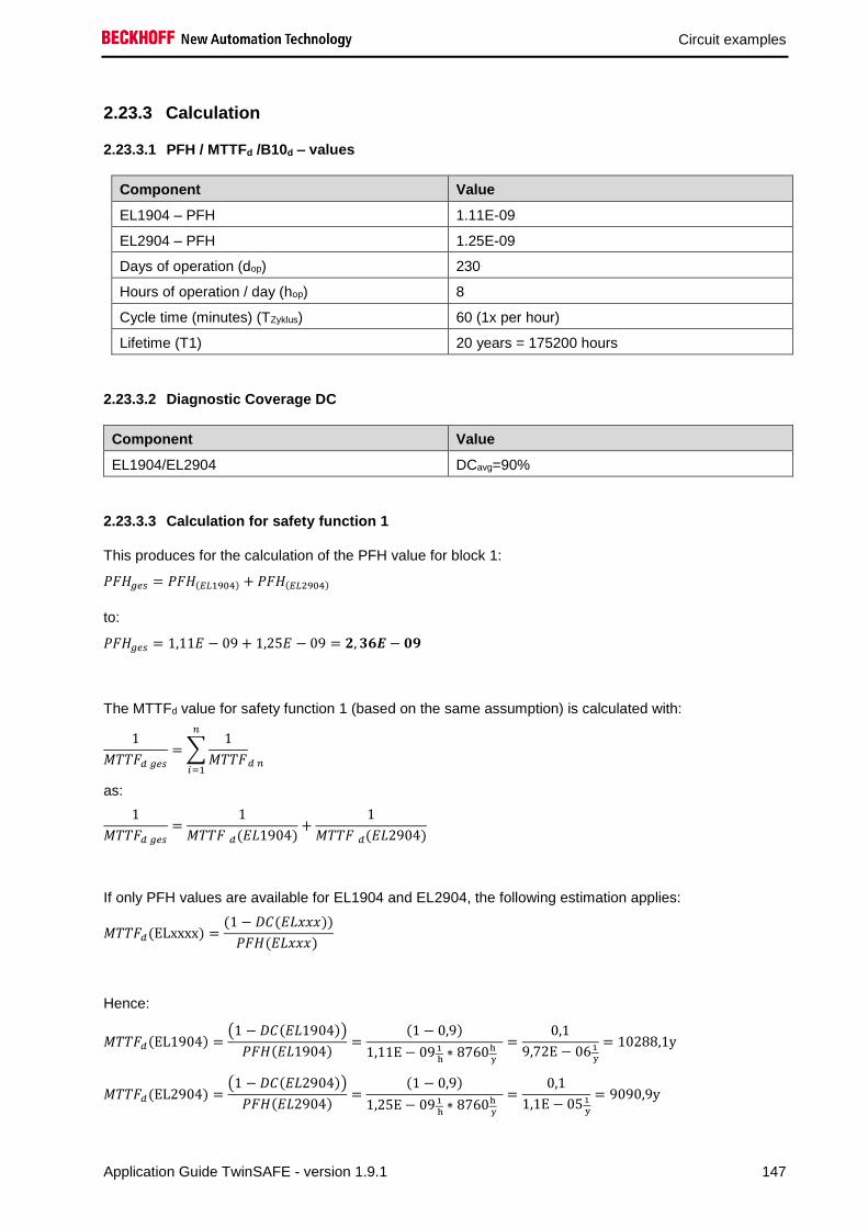
Circuit examples
Application Guide TwinSAFE - version 1.9.1 147
2.23.3 Calculation
2.23.3.1 PFH / MTTFd /B10d – values
Component Value
EL1904 – PFH 1.11E-09
EL2904 – PFH 1.25E-09
Days of operation (dop) 230
Hours of operation / day (hop) 8
Cycle time (minutes) (TZyklus) 60 (1x per hour)
Lifetime (T1) 20 years = 175200 hours
2.23.3.2 Diagnostic Coverage DC
Component Value
EL1904/EL2904 DCavg=90%
2.23.3.3 Calculation for safety function 1
This produces for the calculation of the PFH value for block 1:
𝑃𝐹𝐻𝑔𝑒𝑠 = 𝑃𝐹𝐻(𝐸𝐿1904) + 𝑃𝐹𝐻(𝐸𝐿2904)
to:
𝑃𝐹𝐻𝑔𝑒𝑠 = 1,11𝐸 − 09 + 1,25𝐸 − 09 = 𝟐, 𝟑𝟔𝑬 − 𝟎𝟗
The MTTFd value for safety function 1 (based on the same assumption) is calculated with:
1
𝑀𝑇𝑇𝐹𝑑 𝑔𝑒𝑠
= ∑1
𝑀𝑇𝑇𝐹𝑑 𝑛
𝑛
𝑖=1
as:
1
𝑀𝑇𝑇𝐹𝑑 𝑔𝑒𝑠
=1
𝑀𝑇𝑇𝐹 𝑑(𝐸𝐿1904)+
1
𝑀𝑇𝑇𝐹 𝑑(𝐸𝐿2904)
If only PFH values are available for EL1904 and EL2904, the following estimation applies:
𝑀𝑇𝑇𝐹𝑑(ELxxxx) =(1 − 𝐷𝐶(𝐸𝐿𝑥𝑥𝑥))
𝑃𝐹𝐻(𝐸𝐿𝑥𝑥𝑥)
Hence:
𝑀𝑇𝑇𝐹𝑑(EL1904) =(1 − 𝐷𝐶(𝐸𝐿1904))
𝑃𝐹𝐻(𝐸𝐿1904)=
(1 − 0,9)
1,11E − 09 1
h∗ 8760h
y
=0,1
9,72E − 061
y
= 10288,1y
𝑀𝑇𝑇𝐹𝑑(EL2904) =(1 − 𝐷𝐶(𝐸𝐿2904))
𝑃𝐹𝐻(𝐸𝐿2904)=
(1 − 0,9)
1,25E − 09 1
h∗ 8760h
y
=0,1
1,1E − 051
y
= 9090,9y

Circuit examples
148 Application Guide TwinSAFE - version 1.9.1
𝑀𝑇𝑇𝐹𝐷𝑔𝑒𝑠 =1
1
10288,1𝑦+
1
9090,9𝑦
= 4826,3𝑦
𝐷𝐶𝑎𝑣𝑔 =
90%
10288,1+
90%
10288,1+
90%
9090,9+
90%
9090,91
10288,1+
1
10288,1+
1
9090,9+
1
9090,9
= 90%
Note
Category
This structure is possible up to category 3 at the most.
MTTFd Designation for each channel Range for each channel
low 3 years ≤ MTTFd < 10 years
medium 10 years ≤ MTTFd < 30 years
high 30 years ≤ MTTFd ≤ 100 years
DCavg Designation Range
none DC < 60 %
low 60 % ≤ DC < 90 %
medium 90 % ≤ DC < 99 %
high 99 % ≤ DC
Category B 1 2 2 3 3 4
DC MTTFd
none none low medium low medium high
low a - a b b c -
medium b - b c c d -
high - c c d d d e

Circuit examples
Application Guide TwinSAFE - version 1.9.1 149
2.24 ESTOP function (Category 3, PL d)
The emergency stop button is connected via two normally closed contacts to an EL1904 safe input
terminal. The testing of both signals is switched off. These signals are tested for discrepancy inside the
ESTOP function block. The restart and the feedback signal from the contactors K1 and K2 are wired to
standard terminals and are transferred to TwinSAFE via the standard PLC. Furthermore, the output of the
ESTOP function block and the feedback signal are wired to an EDM block. This checks that the feedback
signal assumes the opposing state of the ESTOP output within the set time.
Contactors K1 and K2 are wired to different output channels. The A2 connections of the two contactors
are fed back to the EL2904. The current measurement of the output channels is deactivated for this
circuit. The testing of the outputs is similarly inactive.
Restart
K1
K2
ESTOP-Button
Logical connection in
EL6900
S1
S2
K1 K2

Circuit examples
150 Application Guide TwinSAFE - version 1.9.1
2.24.1 Parameters of the safe input and output terminals (SIL 2)
EL1904 (applies to all EL1904 used)
Parameter Value
Sensor test channel 1 active -
Sensor test channel 2 active -
Sensor test channel 3 active No
Sensor test channel 4 active No
Logic channel 1 and 2 Single Logic
Logic channel 3 and 4 Single Logic
EL2904
Parameter Value
Current measurement active No
Output test pulses active No
2.24.2 Block formation and safety loops
2.24.2.1 Safety function 1
2.24.3 Calculation
2.24.3.1 PFH / MTTFd /B10d – values
Component Value
EL1904 – PFH 1.11E-09
EL2904 – PFH 1.25E-09
EL6900 – PFH 1.03E-09
S1 – B10d 100,000
S2 – B10d 10,000,000
K1 – B10d 1,300,000
K2 – B10d 1,300,000
Days of operation (dop) 230
Hours of operation / day (hop) 16
Cycle time (minutes) (TZyklus) 10080 (1x per week)
Lifetime (T1) 20 years = 175200 hours
S1 EL1904 EL6900 EL2904
K1
K2

Circuit examples
Application Guide TwinSAFE - version 1.9.1 151
2.24.3.2 Diagnostic Coverage DC
Component Value
S1 with plausibility DCavg=90%
K1/K2 with EDM monitoring (actuation 1x per
week and evaluation of all rising and falling
edges with monitoring over time) with testing of
the individual channels
DCavg=90%
2.24.3.3 Calculation for safety function 1
Calculation of the PFH and MTTFd values from the B10d values:
From:
𝑛𝑜𝑝 =𝑑𝑜𝑝∗ℎ𝑜𝑝∗60
𝑇𝑍𝑦𝑘𝑙𝑢𝑠
and:
𝑀𝑇𝑇𝐹𝑑 =𝐵10𝑑
0,1 ∗ 𝑛𝑜𝑝
Inserting the values, this produces:
S1:
𝑛𝑜𝑝 =230∗16∗60
10080= 21,90
𝑀𝑇𝑇𝐹𝑑 =100000
0,1∗21,90= 45662,1y = 399999120h
K1/K2:
𝑛𝑜𝑝 =230∗16∗60
10080= 21,90
𝑀𝑇𝑇𝐹𝑑 =1300000
0,1 ∗ 21,90= 593607,3y = 5199997320h
and the assumption that S1, K1 and K2 are each single-channel:
𝑀𝑇𝑇𝐹𝑑 =1
𝜆𝑑
produces for
𝑃𝐹𝐻 =0,1 ∗ 𝑛𝑜𝑝 ∗ (1 − 𝐷𝐶)
𝐵10𝑑=
1 − DC
MTTFd
S1:
𝑃𝐹𝐻 =1 − 0,90
45662,1 ∗ 8760= 2,50E − 10
K1/K2: Actuation 1x per week and indirect feedback
𝑃𝐹𝐻 =1 − 0,90
593607,3 ∗ 8760= 1,92E − 11

Circuit examples
152 Application Guide TwinSAFE - version 1.9.1
The following assumptions must now be made:
Safety switch S1: According to BIA report 2/2008, error exclusion to up 100,000 cycles is possible, provided
the manufacturer has confirmed this. If no confirmation exists, S1 is included in the calculation as follows.
Relays K1 and K2 are both connected to the safety function. The non-functioning of a relay does not lead
to a dangerous situation, but it is discovered by the feedback. Furthermore, the B10d values for K1 and
K2 are identical.
There is a coupling coefficient between the components that are connected via two channels. Examples
are temperature, EMC, voltage peaks or signals between these components. This is assumed to be the
worst-case estimation, where ß =10%. EN 62061 contains a table with which this ß-factor can be
precisely determined. Further, it is assumed that all usual measures have been taken to prevent both
channels failing unsafely at the same time due to an error (e.g. overcurrent through relay contacts,
overtemperature in the control cabinet).
This produces for the calculation of the PFH value for safety function 1:
𝑃𝐹𝐻𝑔𝑒𝑠 = 𝑃𝐹𝐻(𝑆1) + 𝑃𝐹𝐻(𝐸𝐿1904) + 𝑃𝐹𝐻(𝐸𝐿6900) + 𝑃𝐹𝐻(𝐸𝐿2904) + 𝛽 ∗𝑃𝐹𝐻(𝐾1) + 𝑃𝐹𝐻(𝐾2)
2+ (1 − 𝛽)2 ∗ (𝑃𝐹𝐻(𝐾1) ∗ 𝑃𝐹𝐻(𝐾2)) ∗ 𝑇1
Since the portion (1 − 𝛽)2 ∗ (𝑃𝐹𝐻(𝐾1) ∗ 𝑃𝐹𝐻(𝐾2)) ∗ 𝑇1 is smaller than the rest by the power of ten, it is
neglected in this and all further calculations for the purpose of simplification.
to:
𝑃𝐹𝐻𝑔𝑒𝑠 = 2,5𝐸 − 10 + 1,11𝐸 − 09 + 1,03𝐸 − 09 + 1,25𝐸 − 09 + 10% ∗1,92𝐸 − 11 + 1,92𝐸 − 11
2= 𝟑, 𝟔𝟒𝑬 − 𝟎𝟗
The MTTFd value for safety function 1 (based on the same assumption) is calculated with:
1
𝑀𝑇𝑇𝐹𝑑 𝑔𝑒𝑠
= ∑1
𝑀𝑇𝑇𝐹𝑑 𝑛
𝑛
𝑖=1
as:
1
𝑀𝑇𝑇𝐹𝑑 𝑔𝑒𝑠
=1
𝑀𝑇𝑇𝐹𝑑 (𝑆1)+
1
𝑀𝑇𝑇𝐹𝑑(𝐸𝐿1904)+
1
𝑀𝑇𝑇𝐹𝑑 (𝐸𝐿6900)+
1
𝑀𝑇𝑇𝐹𝑑(𝐸𝐿2904)+
1
𝑀𝑇𝑇𝐹𝑑 (𝐾1)
with:
𝑀𝑇𝑇𝐹𝑑(S1) =𝐵10𝑑(𝑆1)
0,1 ∗ 𝑛𝑜𝑝
= 45662,1y
𝑀𝑇𝑇𝐹𝑑(K1) =𝐵10𝑑(𝐾1)
0,1 ∗ 𝑛𝑜𝑝
= 593607,3y

Circuit examples
Application Guide TwinSAFE - version 1.9.1 153
If only PFH values are available for EL1904, EL2904 and EL6900, the following estimation applies:
𝑀𝑇𝑇𝐹𝑑(ELxxxx) =(1 − 𝐷𝐶(𝐸𝐿𝑥𝑥𝑥))
𝑃𝐹𝐻(𝐸𝐿𝑥𝑥𝑥)
Hence:
𝑀𝑇𝑇𝐹𝑑(EL1904) =(1 − 𝐷𝐶(𝐸𝐿1904))
𝑃𝐹𝐻(𝐸𝐿1904)=
(1 − 0,99)
1,11E − 09 1
h∗ 8760h
y
=0,01
9,72E − 061
y
= 1028,8y
𝑀𝑇𝑇𝐹𝑑(EL6900) =(1 − 𝐷𝐶(𝐸𝐿6900))
𝑃𝐹𝐻(𝐸𝐿6900) =
(1 − 0,99)
1,03E − 091
h∗ 8760h
y
=0,01
9,02E − 061
y
= 1108,6y
𝑀𝑇𝑇𝐹𝑑(EL2904) =(1 − 𝐷𝐶(𝐸𝐿2904))
𝑃𝐹𝐻(𝐸𝐿2904) =
(1 − 0,99)
1,25E − 091
h∗ 8760h
y
=0,01
1,1E − 051
y
= 913,2y
𝑀𝑇𝑇𝐹𝐷𝑔𝑒𝑠 =1
1
45662,1𝑦+
1
1028,8𝑦+
1
1108,6𝑦+
1
913,2𝑦+
1
593607,3𝑦
= 334,1𝑦
𝐷𝐶𝑎𝑣𝑔 =
90%
45662,1+
99%
1028,8+
99%
1108,6+
99%
913,2+
90%
593607,3+
90%
593607,31
45662,1+
1
1028,8+
1
1108,6+
1
913,2+
1
593607,3+
1
593607,3
= 98,92%
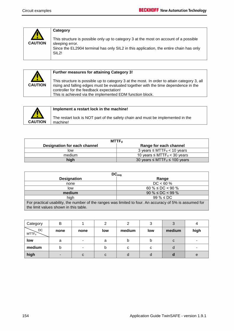
Circuit examples
154 Application Guide TwinSAFE - version 1.9.1
CAUTION
Category
This structure is possible only up to category 3 at the most on account of a possible sleeping error.
Since the EL2904 terminal has only SIL2 in this application, the entire chain has only
SIL2!
CAUTION
Further measures for attaining Category 3!
This structure is possible up to category 3 at the most. In order to attain category 3, all rising and falling edges must be evaluated together with the time dependence in the controller for the feedback expectation! This is achieved via the implemented EDM function block.
CAUTION
Implement a restart lock in the machine!
The restart lock is NOT part of the safety chain and must be implemented in the machine!
MTTFd Designation for each channel Range for each channel
low 3 years ≤ MTTFd < 10 years
medium 10 years ≤ MTTFd < 30 years
high 30 years ≤ MTTFd ≤ 100 years
DCavg Designation Range
none DC < 60 %
low 60 % ≤ DC < 90 %
medium 90 % ≤ DC < 99 %
high 99 % ≤ DC
For practical usability, the number of the ranges was limited to four. An accuracy of 5% is assumed for
the limit values shown in this table.
Category B 1 2 2 3 3 4
DC MTTFd
none none low medium low medium high
low a - a b b c -
medium b - b c c d -
high - c c d d d e

Circuit examples
Application Guide TwinSAFE - version 1.9.1 155
2.25 Speed monitoring (Category 3, PL d)
The speed of a drive is to be monitored. This drive has a safety function (in this case, for example, STO),
which is activated via a corresponding input. This input is conducted through one working contact of each
of two contactors.
The position and speed signals are transmitted via two different communication paths to the EL6910
TwinSAFE logic and processed there according to the illustrated logic. The Sin/Cos encoder is connected
to an EL5021-0090 and the position information is transmitted by TwinSAFE SC communication over
EtherCAT. The speed of the drive is transferred to the EL6910 TwinSAFE logic over the standard
PROFINET communication (any other fieldbus is also possible) and the standard PLC.
A speed (FB Speed) is calculated from the position value within the safety-related EL6910 logic. The
speed of the drive is scaled via the FB so that the value matches the calculated speed. These two speed
values are checked by the FB Compare for equality and monitored by the FB Limit for a maximum value.
Since the two speed values (one calculated directly and the other calculated in the safety-related EL6910
logic) are never 100% equal at any time, the difference between the two speed values should be within a
tolerance band of 10% in order to still to meet the condition of equality. If the current speed value is below
the threshold specified in the FB Limit, the STO output is set to logical 1 and the drive can rotate. If the
limit is exceeded or if the comparison fails, the output is set to logical 0 and the drive is switched to
torque-free or the safety function integrated in the drive is activated. The entire calculation and scaling is
performed at the SIL3/PL e safety level in the safety-related EL6910 logic. Using this method, a safety-
related result is created from two non-safety-related signals.
An emergency stop function is additionally implemented by an ESTOP function block (not shown in the
diagram for reasons of clarity), which prevents the restart and also takes over the control of contactors K1
and K2.
The IsValid signal of the Compare function block must be used to switch off in case of a fault.
Structure
PLC
Drive
Motor Encoder
fieldbus e.g. PROFInet fieldbus e.g. EtherCAT
Speed
EL69
10
EL5021-0090
Sin/Cos 1Vss
TwinSAFE SC – position value
standard communication - Speed
Logic see below
STO
K1
K2
24Vdc
K1 K2

Circuit examples
156 Application Guide TwinSAFE - version 1.9.1
Diagram of the structure
motor
Encodersin/cos
EL5021-0090
PCblack channelencoder signal
actuatorEL2904EL6910
Drive
motor shaft
motor cablestandard fieldbus
actual speed
Logic
TwinSAFE SC Communication –
Position value
Standard Communication - Speed
STO - Drive
STO - Drive
Restart
Estop In1
Estop In2
Feedback K1/K2
K1/K2
500
1500
EStopInx

Circuit examples
Application Guide TwinSAFE - version 1.9.1 157
2.25.1 Structure and diagnosis
The input signals from the drive and the encoder are standard signals, which are dynamic and different.
The drive supplies a speed value and the encoder a sin/cos signal, which is evaluated by a standard
terminal, packaged in a safe telegram (FSoE with changed polynomial - TwinSAFE SC) and transmitted.
This terminal (EL5021-0090) supplies a position value that is converted within the safe logic to a speed
value, then scaled and compared with the speed value of the drive. Equality means in this case that the
difference signal lies within the tolerance window of 10%.
The encoder signal is transmitted via the standard fieldbus using the black channel principle. This value is
checked for plausibility against the drive speed that is transmitted via the standard fieldbus. Errors in one
of the two channels are detected by means of the comparison of the two diverse speed and position
signals within the safe logic and lead to the activation of STO of the drive.
2.25.2 FMEA
Error assumption Expectations Checked
Speed value over e.g.
PROFINET itself freezes
Detected via the second value and the plausibility check
in the EL6910 (other fieldbus and TwinSAFE SC
communication between EL5021-0090 and EL6910).
In addition, the standard communication watchdog
should be activated for the speed 0.
Speed value over EtherCAT
and TwinSAFE SC
communication freezes
Detected by the watchdog within the TwinSAFE SC
communication.
Plausibility check: Dynamic speed values are also
expected when the motor is started.
Speed values are copied in
succession in the standard PLC
A corrupt value within the TwinSAFE SC communication
results in an invalid CRC inside the telegram and thus
the immediate cut-off of the group and the outputs
The data types of the two speed values have a different
length (e.g. 4 bytes and 11 bytes)
Speed value via e.g.
PROFINET is corrupted
Detected via the second value and the plausibility check
in the EL6910 (other fieldbus and TwinSAFE SC
communication between EL5021-0090 and EL6910).
There is no longer any
connection between the motor
and the encoder
Detected within the EL6910 via the plausibility check
with the speed value of the drive.
Plausibility check: Dynamic speed values are also
expected when the motor is started.
Encoder supplies an incorrect
position value
Detected within the EL6910 via the plausibility check
with the speed value of the drive
Drive supplies incorrect speed
value
Detected via the second value and the plausibility check
in the EL6910 (other fieldbus and TwinSAFE SC
communication between EL5021-0090 and EL6910).
Communication error 61784-3
for standard communication:
Corruption
Detected within the EL6910 via the plausibility check of
the speed values with the TwinSAFE SC communication
Communication error 61784-3
for standard communication:
Unintentional repetition
Detected within the EL6910 via the plausibility check of
the speed values with the TwinSAFE SC
communication. In addition, the standard communication
watchdog should be activated for the speed 0.
Communication error 61784-3
for standard communication:
Wrong sequence
Detected within the EL6910 via the plausibility check of
the speed values with the TwinSAFE SC communication

Circuit examples
158 Application Guide TwinSAFE - version 1.9.1
Error assumption Expectations Checked
Communication error 61784-3
for standard communication:
Loss
Detected within the EL6910 via the plausibility check of
the speed values with the TwinSAFE SC communication
Communication error 61784-3
for standard communication:
Unacceptable delay
Detected within the EL6910 via the plausibility check of
the speed values with the TwinSAFE SC
communication. In addition, the standard communication
watchdog should be activated for the speed 0.
Communication error 61784-3
for standard communication:
Insertion
Detected within the EL6910 via the plausibility check of
the speed values with the TwinSAFE SC communication
Communication error 61784-3
for standard communication:
Masquerading
not relevant for standard, only for safety communication.
Communication error 61784-3
for standard communication:
Addressing
Detected within the EL6910 via the plausibility check of
the speed values with the TwinSAFE SC communication
Communication error for
standard communication:
Recurrent memory errors in
switches
Detected within the EL6910 via the plausibility check of
the speed values with the TwinSAFE SC communication
2.25.2.1 Note about TwinSAFE SC communication:
The TwinSAFE SC communication uses the identical mechanisms for error detection as the Safety-over-
EtherCAT communication, the difference being that a different polynomial is used to calculate the
checksum and this polynomial is sufficiently independent of the polynomial previously used for Safety-
over-EtherCAT.
The identical mechanisms are active, such as the black channel principle (bit error probability 10-2).
The quality of the data transmission is not crucial, because ultimately all transmission errors are detected
via the comparison in the safe logic, since this would lead to inequality.

Circuit examples
Application Guide TwinSAFE - version 1.9.1 159
2.25.3 Parameters of the safe output terminal
EL2904
Parameter Value
Current measurement active Yes
Output test pulses active Yes
2.25.4 Block formation and safety loops
2.25.4.1 Safety function 1
Drive
EL5021-0090
EL6910 EL2904
K1
K2Encoder
Input1
2.25.5 Calculation
2.25.5.1 PFH / MTTFd /B10d – values
Component Value
EL1904 – PFH 1.11E-09
EL2904 – PFH 1.25E-09
EL6910 – PFH 1.79E-09
Drive MTBF 516,840 (59a)
Encoder – MTTF 549,149
EL5021-0090 - MTBF 1,205,000
K1 – B10d 1,300,000
K2 – B10d 1,300,000
Days of operation (dop) 230
Hours of operation / day (hop) 16
Cycle time (minutes) (TZyklus) 10080 (1x per week)
Lifetime (T1) 20 years = 175200 hours

Circuit examples
160 Application Guide TwinSAFE - version 1.9.1
2.25.5.2 Diagnostic Coverage DC
Component Value
Drive and encoder with EL5021-0090 and
plausibility within the logic
DCavg = 90% (alternative in the calculation: 99%)
K1/K2 with EDM monitoring (actuation 1x per
week and evaluation of all rising and falling
edges with monitoring over time) without testing
of the individual channels
DCavg = 99%
2.25.5.3 Calculation of safety function 1
For clarification, the safety parameter is calculated according to both EN62061 and EN13849. Calculation according to one standard is sufficient in practice.
Calculation of the PFH and MTTFd values from the B10d values:
From:
𝑛𝑜𝑝 =𝑑𝑜𝑝∗ℎ𝑜𝑝∗60
𝑇𝑍𝑦𝑘𝑙𝑢𝑠
and:
𝑀𝑇𝑇𝐹𝑑 =𝐵10𝑑
0,1 ∗ 𝑛𝑜𝑝
Calculation of the PFH and MTTFd values from the MTBF values:
Note: Repair times can be neglected, therefore the following applies:
𝑀𝑇𝑇𝐹𝑑 = 2 ∗ 𝑀𝑇𝐵𝐹
𝑀𝑇𝑇𝐹𝑑 =1
𝜆𝑑
with
𝜆𝑑 ≈0,1
𝑇10𝑑=
0,1 ∗ 𝑛𝑜𝑝
𝐵10𝑑
produces for
𝑃𝐹𝐻 =0,1 ∗ 𝑛𝑜𝑝 ∗ (1 − 𝐷𝐶)
𝐵10𝑑=
1 − DC
MTTFd
Inserting the values, this produces:
Drive:
𝑀𝑇𝑇𝐹𝑑 = 2 ∗ 𝑀𝑇𝐵𝐹 = 2 ∗ 59 = 1.033.680 ℎ = 118𝑦
𝑃𝐹𝐻 =1 − DC
MTTFd=
1 − 0,9
1.033.680 ℎ= 9,67E − 08
Encoder:
𝑀𝑇𝑇𝐹𝑑 = 2 ∗ 𝑀𝑇𝑇𝐹 = 2 ∗ 549149 = 1.098.298 ℎ = 125𝑦
𝑃𝐹𝐻 =1 − DC
MTTFd=
1 − 0,9
1.098.298 ℎ= 9,10E − 08

Circuit examples
Application Guide TwinSAFE - version 1.9.1 161
EL5021-0090
𝑀𝑇𝑇𝐹𝑑 = 2 ∗ 𝑀𝑇𝐵𝐹 = 2 ∗ 1.205.000 ℎ = 2.410.000 ℎ = 275𝑦
𝑃𝐹𝐻 =1 − DC
MTTFd=
1 − 0,9
2.410.000 ℎ= 4,15E − 08
Input subsystem 1
𝑃𝐹𝐻(𝐼𝑛𝑝𝑢𝑡1) = 𝑃𝐹𝐻(𝐸𝑛𝑐𝑜𝑑𝑒𝑟) + 𝑃𝐹𝐻(𝐸𝐿5021−0090) = 9,10𝐸 − 08 + 4,15𝐸 − 08 = 13,25𝐸 − 08
K1/K2:
𝑛𝑜𝑝 =230∗16∗60
10080= 21,90
𝑀𝑇𝑇𝐹𝑑 =1300000
0,1 ∗ 21,90= 593607y = 5.199.997.320h
and the assumption that K1 and K2 are each single-channel:
K1/K2: Actuation 1x per week and direct feedback
𝑃𝐹𝐻 =1 − 0,99
593607,3 ∗ 8760= 1,92E − 12
The following assumptions must now be made:
Relays K1 and K2 are both connected to the safety function. The non-functioning of a relay does not lead
to a dangerous situation, but it is discovered by the feedback. Furthermore, the B10d values for K1 and
K2 are identical.
The input signals from encoder with EL5021-0090 and drive have different measuring methods, provide
differently scaled values and are both involved in the safety function. A non-functioning of a channel does
not lead to a dangerous situation, but is detected by the comparison of the two values in the TwinSAFE
logic and leads to a shutdown.
There is a coupling coefficient between the components that are connected via two channels. Examples
are temperature, EMC, voltage peaks or signals between these components. This is assumed to be the
worst-case estimation, where ß =10%. EN 62061 contains tables (Table F.1 criteria for the determination
of the CCF and Table F.2 estimation of the CCF factor (β)) with which this β factor can be determined
exactly. For the input subsystem an estimated value of 2% can be achieved by processing the table to
calculate the β factor. In the following calculation, the worst case is assumed to be 10%.
Further, it is assumed that all usual measures have been taken to prevent both channels failing unsafely
at the same time due to an error (e.g. overcurrent through relay contacts, overtemperature in the control
cabinet)
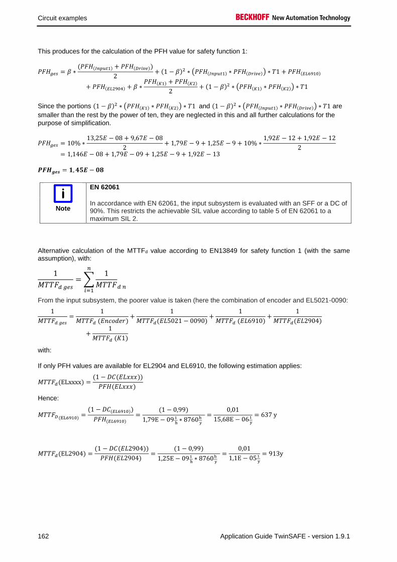
Circuit examples
162 Application Guide TwinSAFE - version 1.9.1
This produces for the calculation of the PFH value for safety function 1:
𝑃𝐹𝐻𝑔𝑒𝑠 = 𝛽 ∗(𝑃𝐹𝐻(𝐼𝑛𝑝𝑢𝑡1) + 𝑃𝐹𝐻(𝐷𝑟𝑖𝑣𝑒))
2+ (1 − 𝛽)2 ∗ (𝑃𝐹𝐻(𝐼𝑛𝑝𝑢𝑡1) ∗ 𝑃𝐹𝐻(𝐷𝑟𝑖𝑣𝑒)) ∗ 𝑇1 + 𝑃𝐹𝐻(𝐸𝐿6910)
+ 𝑃𝐹𝐻(𝐸𝐿2904) + 𝛽 ∗𝑃𝐹𝐻(𝐾1) + 𝑃𝐹𝐻(𝐾2)
2+ (1 − 𝛽)2 ∗ (𝑃𝐹𝐻(𝐾1) ∗ 𝑃𝐹𝐻(𝐾2)) ∗ 𝑇1
Since the portions (1 − 𝛽)2 ∗ (𝑃𝐹𝐻(𝐾1) ∗ 𝑃𝐹𝐻(𝐾2)) ∗ 𝑇1 and (1 − 𝛽)2 ∗ (𝑃𝐹𝐻(𝐼𝑛𝑝𝑢𝑡1) ∗ 𝑃𝐹𝐻(𝐷𝑟𝑖𝑣𝑒)) ∗ 𝑇1 are
smaller than the rest by the power of ten, they are neglected in this and all further calculations for the
purpose of simplification.
𝑃𝐹𝐻𝑔𝑒𝑠 = 10% ∗13,25𝐸 − 08 + 9,67𝐸 − 08
2+ 1,79𝐸 − 9 + 1,25𝐸 − 9 + 10% ∗
1,92𝐸 − 12 + 1,92𝐸 − 12
2= 1,146𝐸 − 08 + 1,79𝐸 − 09 + 1,25𝐸 − 9 + 1,92𝐸 − 13
𝑷𝑭𝑯𝒈𝒆𝒔 = 𝟏, 𝟒𝟓𝑬 − 𝟎𝟖
Note
EN 62061
In accordance with EN 62061, the input subsystem is evaluated with an SFF or a DC of 90%. This restricts the achievable SIL value according to table 5 of EN 62061 to a maximum SIL 2.
Alternative calculation of the MTTFd value according to EN13849 for safety function 1 (with the same assumption), with:
1
𝑀𝑇𝑇𝐹𝑑 𝑔𝑒𝑠= ∑
1
𝑀𝑇𝑇𝐹𝑑 𝑛
𝑛
𝑖=1
From the input subsystem, the poorer value is taken (here the combination of encoder and EL5021-0090:
1
𝑀𝑇𝑇𝐹𝑑 𝑔𝑒𝑠
=1
𝑀𝑇𝑇𝐹𝑑 (𝐸𝑛𝑐𝑜𝑑𝑒𝑟)+
1
𝑀𝑇𝑇𝐹𝑑(𝐸𝐿5021 − 0090)+
1
𝑀𝑇𝑇𝐹𝑑 (𝐸𝐿6910)+
1
𝑀𝑇𝑇𝐹𝑑(𝐸𝐿2904)
+1
𝑀𝑇𝑇𝐹𝑑 (𝐾1)
with:
If only PFH values are available for EL2904 and EL6910, the following estimation applies:
𝑀𝑇𝑇𝐹𝑑(ELxxxx) =(1 − 𝐷𝐶(𝐸𝐿𝑥𝑥𝑥))
𝑃𝐹𝐻(𝐸𝐿𝑥𝑥𝑥)
Hence:
𝑀𝑇𝑇𝐹𝐷 (EL6910)=
(1 − 𝐷𝐶(𝐸𝐿6910))
𝑃𝐹𝐻(𝐸𝐿6910) =
(1 − 0,99)
1,79E − 09 1
h∗ 8760h
y
=0,01
15,68E − 061
y
= 637 y
𝑀𝑇𝑇𝐹𝑑(EL2904) =(1 − 𝐷𝐶(𝐸𝐿2904))
𝑃𝐹𝐻(𝐸𝐿2904) =
(1 − 0,99)
1,25E − 091
h∗ 8760h
y
=0,01
1,1E − 051
y
= 913y

Circuit examples
Application Guide TwinSAFE - version 1.9.1 163
𝑀𝑇𝑇𝐹𝐷 𝑔𝑒𝑠 =1
1
125+
1
275+
1
637+
1
913+
1
593607
= 69,9 𝑦
𝐷𝐶𝑎𝑣𝑔𝑠 =
𝐷𝐶
𝑀𝑇𝑇𝐹𝑑(𝐸𝑛𝑐𝑜𝑑𝑒𝑟)+
𝐷𝐶
𝑀𝑇𝑇𝐹𝑑(𝐸𝐿5021−0090)+
𝐷𝐶
𝑀𝑇𝑇𝐹𝑑(𝐷𝑟𝑖𝑣𝑒)+
𝐷𝐶
𝑀𝑇𝑇𝐹𝑑(𝐸𝐿6910)+
𝐷𝐶
𝑀𝑇𝑇𝐹𝑑(𝐸𝐿2904)+
𝐷𝐶
𝑀𝑇𝑇𝐹𝑑(𝐾1)+
𝐷𝐶
𝑀𝑇𝑇𝐹𝑑(𝐾2)
1
𝑀𝑇𝑇𝐹𝑑(𝐸𝑛𝑐𝑜𝑑𝑒𝑟)+
1
𝑀𝑇𝑇𝐹𝑑(𝐸𝐿5021−0090)+
1
𝑀𝑇𝑇𝐹𝑑(𝐷𝑟𝑖𝑣𝑒)+
1
𝑀𝑇𝑇𝐹𝑑(𝐸𝐿6910)+
1
𝑀𝑇𝑇𝐹𝑑(𝐸𝐿2904)+
1
𝑀𝑇𝑇𝐹𝑑(𝐾1)+
1
𝑀𝑇𝑇𝐹𝑑(𝐾2)
𝐷𝐶𝑎𝑣𝑔𝑠 =
0,9
125+
0,9
275+
0,9
118+
0,99
637+
0,99
913+
0,99
593607+
0,99
5936071
125+
1
275+
1
118+
1
637+
1
913+
1
593607+
1
593607
=0,0207
0,0228= 90,78%
Alternatively with DC = 99%
𝐷𝐶𝑎𝑣𝑔𝑠 =
0,99
125+
0,99
275+
0,99
118+
0,99
637+
0,99
913+
0,99
593607+
0,99
5936071
125+
1
275+
1
118+
1
637+
1
913+
1
593607+
1
593607
=0,0226
0,0228= 99,12%

Circuit examples
164 Application Guide TwinSAFE - version 1.9.1
CAUTION
Category
This structure is possible up to category 3 at the most.
WARNING
Standstill
When the motor is stopped, an error such as the freezing of an encoder signal is detected only if a movement is requested. The machine manufacturer or user must take this into account.
CAUTION
Implement a restart lock in the machine!
The restart lock is NOT part of the safety chain and must be implemented in the machine!
MTTFd Designation for each channel Range for each channel
low 3 years ≤ MTTFd < 10 years
medium 10 years ≤ MTTFd < 30 years
high 30 years ≤ MTTFd ≤ 100 years
DCavg Designation Range
none DC < 60 %
low 60 % ≤ DC < 90 %
medium 90 % ≤ DC < 99 %
high 99 % ≤ DC
For practical usability, the number of the ranges was limited to four. An accuracy of 5% is assumed for
the limit values shown in this table.
Category B 1 2 2 3 3 4
DC MTTFd
none none low medium low medium high
low a - a b b c -
medium b - b c c d -
high - c c d d d e

Circuit examples
Application Guide TwinSAFE - version 1.9.1 165
Alternative with DC = 99% for the input subsystem:
MTTFd Designation for each channel Range for each channel
low 3 years ≤ MTTFd < 10 years
medium 10 years ≤ MTTFd < 30 years
high 30 years ≤ MTTFd ≤ 100 years
DCavg Name Range
none DC < 60 %
low 60 % ≤ DC < 90 %
medium 90 % ≤ DC < 99 %
high 99 % ≤ DC
For practical usability, the number of the ranges was limited to four. An accuracy of 5% is assumed for
the limit values shown in this table.
Category B 1 2 2 3 3 4
DC MTTFd
none none low medium low medium high
low a - a b b c -
medium b - b c c d -
high - c c d d d e
Safety integrity level according to Tab. 3 EN62061 Safety integrity level Probability of a dangerous failure per hour
(PFHD)
3 ≥ 10-8 to < 10-7
2 ≥ 10-7 to < 10-6
1 ≥ 10-6 to < 10-5

Circuit examples
166 Application Guide TwinSAFE - version 1.9.1
2.26 Speed monitoring (via IO-link) (Category 3, PL d)
The speed of a drive is to be monitored. This drive has a safety function (in this case, for example, STO),
which is activated via a corresponding input. This input is conducted through one working contact of each
of two contactors.
The speed signals are transmitted in two different ways to the EL6910 TwinSAFE logic and processed
there according to the illustrated logic. The IO-link encoder is wired to an EL6224-0090 and the speed
information is transmitted via TwinSAFE SC communication over PROFINET, for example. The speed of
the drive is transferred to the EL6910 TwinSAFE logic over the standard PROFINET communication (any
other fieldbus is also possible) and the standard PLC.
The two speeds are scaled by the FB Scale within the safety-related EL6910 logic so that the values
match each other. These two speed values are checked by the FB Compare for equality and monitored
by the FB Limit for a maximum value. Since the two speed values are never 100% equal at any time, the
difference between the two speed values should be within a tolerance band of 10% in order to still to
meet the condition of equality. If the current speed value is below the threshold specified in the FB Limit,
the STO output is set to logical 1 and the drive can rotate. If the limit is exceeded or if the comparison
fails, the output is set to logical 0 and the drive is switched to torque-free or the safety function integrated
in the drive is activated. The entire calculation and scaling are performed at the SIL3/PL e safety level in
the safety-related EL6910 logic. Using this method, a safety-related result is created from two non-safety-
related signals.
An emergency stop function is additionally implemented by an ESTOP function block (not shown in the
diagram for reasons of clarity), which prevents the restart and also takes over the control of contactors K1
and K2.
The IsValid signal of the Compare function block must be used to switch off in case of a fault.
IO-Link structure
PLC
Drive
Motor Encoder
fieldbus e.g. PROFInet fieldbus e.g. EtherCAT
Speed
EL6
91
0
standard communication - speed
Logic see below
STO
K1
K2
24Vdc
K1 K2
standard communication – speed over IO-link
EL6224-0090IO-Link Master
TwinSAFE SC – speed

Circuit examples
Application Guide TwinSAFE - version 1.9.1 167
Diagram of the structure
Motor
EncoderIO-Link
EL6224-0090
PCBlackChannel
speedactuatorEL2904EL6910
Drive
motor shaft
motor cablestandard fieldbus
actual speed
logic
TwinSAFE SC Communication – Speed
Standard Communication - Speed
STO - Drive
STO - Drive
Restart
Estop In1
Estop In2
Feedback K1/K2
K1/K2
500
1500
EStopInx

Circuit examples
168 Application Guide TwinSAFE - version 1.9.1
2.26.1 Structure and diagnosis
The input signals read from the drive and the encoder are standard signals, but they are very different.
The drive supplies a speed value and the encoder an IO-Link signal, which is evaluated by a standard
terminal, packaged in a safe telegram (FSoE with changed polynomial - TwinSAFE SC) and transmitted.
This terminal (EL6224-0090) supplies a position value that is scaled within the safe logic and compared
with the speed value of the drive. Equality means in this case that the difference signal lies within the
tolerance window of 10%.
The IO-link encoder signal is transmitted via the standard fieldbus using the black channel principle. This
value is checked for plausibility against the drive speed that is transmitted via the standard fieldbus.
Errors in one of the two channels are detected immediately within the safe logic and lead to the activation
of the STO of the drive.
2.26.2 FMEA
Error assumption Expectations Checked
Speed value over e.g.
PROFINET itself freezes
Detected via the second value and the plausibility check
in the EL6910 (TwinSAFE SC communication between
EL6224-0090 and EL6910)
In addition, the standard communication watchdog
should be activated for the speed 0.
Speed value over EtherCAT
and TwinSAFE SC
communication freezes
Detected by the watchdog within the TwinSAFE SC
communication.
Plausibility check: Dynamic speed values are also
expected when the motor is started.
Speed values are copied in
succession in the standard PLC
A corrupt value within the TwinSAFE SC communication
results in an invalid CRC inside the telegram and thus
the immediate cut-off of the group and the outputs
The data types of the two speed values have a different
length (e.g. 4 bytes and 11 bytes)
Speed value via e.g.
PROFINET is corrupted
Detected via the second value and the plausibility check
in the EL6910 (TwinSAFE SC communication between
EL6224-0090 and EL6910)
There is no longer any
connection between the motor
and the encoder
Detected within the EL6910 via the plausibility check
with the speed value of the drive
Plausibility check: Dynamic speed values are also
expected when the motor is started.
Encoder supplies an incorrect
position value
Detected within the EL6910 via the plausibility check
with the speed value of the drive
Drive supplies incorrect speed
value
Detected via the second value and the plausibility check
in the EL6910 (TwinSAFE SC communication between
EL6224-0090 and EL6910)
Communication error 61784-3
for standard communication:
Corruption
Detected within the EL6910 via the plausibility check of
the speed values with the TwinSAFE SC communication
Communication error 61784-3
for standard communication:
Unintentional repetition
Detected within the EL6910 via the plausibility check of
the speed values with the TwinSAFE SC
communication. In addition, the standard communication
watchdog should be activated for the speed 0.
Communication error 61784-3
for standard communication:
Wrong sequence
Detected within the EL6910 via the plausibility check of
the speed values with the TwinSAFE SC communication

Circuit examples
Application Guide TwinSAFE - version 1.9.1 169
Error assumption Expectations Checked
Communication error 61784-3
for standard communication:
Loss
Detected within the EL6910 via the plausibility check of
the speed values with the TwinSAFE SC communication
Communication error 61784-3
for standard communication:
Unacceptable delay
Detected within the EL6910 via the plausibility check of
the speed values with the TwinSAFE SC
communication. In addition, the standard communication
watchdog should be activated for the speed 0.
Communication error 61784-3
for standard communication:
Insertion
Detected within the EL6910 via the plausibility check of
the speed values with the TwinSAFE SC communication
Communication error 61784-3
for standard communication:
Masquerading
not relevant for standard, only for safety communication.
Communication error 61784-3
for standard communication:
Addressing
Detected within the EL6910 via the plausibility check of
the speed values with the TwinSAFE SC communication
Communication error for
standard communication:
Recurrent memory errors in
switches
Detected within the EL6910 via the plausibility check of
the speed values with the TwinSAFE SC communication
2.26.2.1 Note about TwinSAFE SC communication:
The TwinSAFE SC communication uses the identical mechanisms for error detection as the Safety-over-
EtherCAT communication, the difference being that a different polynomial is used to calculate the
checksum and this polynomial is sufficiently independent of the polynomial previously used for Safety-
over-EtherCAT.
The identical mechanisms are active, such as the black channel principle (bit error probability 10-2).
The quality of the data transmission is not crucial, because ultimately all transmission errors are detected via the comparison in the safe logic, since this would lead to inequality.

Circuit examples
170 Application Guide TwinSAFE - version 1.9.1
2.26.3 Parameters of the safe output terminal
EL2904
Parameter Value
Current measurement active Yes
Output test pulses active Yes
2.26.4 Block formation and safety loops
2.26.4.1 Safety function 1
Drive
EL6224-0090
EL6910 EL2904
K1
K2Encoder
Input1
2.26.5 Calculation
2.26.5.1 PFH / MTTFd /B10d – values
Component Value
EL1904 – PFH 1.11E-09
EL2904 – PFH 1.25E-09
EL6910 – PFH 1.79E-09
Drive MTBF 516,840 (59y)
Encoder – MTTF 1.208.880 (138y)
EL6224-0090 - MTBF 1,200,000
K1 – B10d 1,300,000
K2 – B10d 1,300,000
Days of operation (dop) 230
Hours of operation / day (hop) 16
Cycle time (minutes) (TZxklus) 10080 (1x per week)
Lifetime (T1) 20 years = 175200 hours

Circuit examples
Application Guide TwinSAFE - version 1.9.1 171
2.26.5.2 Diagnostic Coverage DC
Component Value
Drive and encoder with EL6224-0090 and
plausibility within the logic
DCavg = 90% (alternative in the calculation: 99%)
K1/K2 with EDM monitoring (actuation 1x per
week and evaluation of all rising and falling
edges with monitoring over time) without testing
of the individual channels
DCavg=99%
2.26.5.3 Calculation of safety function 1
For clarification, the safety parameter is calculated according to both EN62061 and EN13849. Calculation according to one standard is sufficient in practice.
Calculation of the PFH and MTTFd values from the B10d values:
From:
𝑛𝑜𝑝 =𝑑𝑜𝑝∗ℎ𝑜𝑝∗60
𝑇𝑍𝑦𝑘𝑙𝑢𝑠
and:
𝑀𝑇𝑇𝐹𝑑 =𝐵10𝑑
0,1 ∗ 𝑛𝑜𝑝
Calculation of the PFH and MTTFd values from the MTBF values:
Note: Repair times can be neglected, therefore the following applies:
𝑀𝑇𝑇𝐹𝑑 = 2 ∗ 𝑀𝑇𝐵𝐹
𝑀𝑇𝑇𝐹𝑑 =1
𝜆𝑑
with
𝜆𝑑 ≈0,1
𝑇10𝑑
=0,1 ∗ 𝑛𝑜𝑝
𝐵10𝑑
produces for
𝑃𝐹𝐻 =0,1 ∗ 𝑛𝑜𝑝 ∗ (1 − 𝐷𝐶)
𝐵10𝑑
=1 − DC
MTTFd
Inserting the values, this produces:
Drive 𝑀𝑇𝑇𝐹𝑑 = 2 ∗ 𝑀𝑇𝐵𝐹 = 2 ∗ 59 = 1.033.680 ℎ = 118𝑦
𝑃𝐹𝐻 =1 − DC
MTTFd
=1 − 0,9
1.033.680 ℎ= 9,67E − 08
Encoder 𝑀𝑇𝑇𝐹𝑑 = 2 ∗ 𝑀𝑇𝑇𝐹 = 2 ∗ 549149 = 1.208.880ℎ = 138𝑦
𝑃𝐹𝐻 =1 − DC
MTTFd
=1 − 0,9
1.208.880 ℎ= 8,27E − 08

Circuit examples
172 Application Guide TwinSAFE - version 1.9.1
EL6224-0090 𝑀𝑇𝑇𝐹𝑑 = 2 ∗ 𝑀𝑇𝐵𝐹 = 2 ∗ 1.200.000 ℎ = 2.400.000 ℎ = 273𝑦
𝑃𝐹𝐻 =1 − DC
MTTFd
=1 − 0,9
2.400.000 ℎ= 4,17E − 08
Input subsystem 1
𝑃𝐹𝐻(𝐼𝑛𝑝𝑢𝑡1) = 𝑃𝐹𝐻(𝐸𝑛𝑐𝑜𝑑𝑒𝑟) + 𝑃𝐹𝐻(𝐸𝐿6224−0090) = 8,27𝐸 − 08 + 4,17𝐸 − 08 = 12,44𝐸 − 08
K1/K2:
𝑛𝑜𝑝 =230∗16∗60
10080= 21,90
𝑀𝑇𝑇𝐹𝑑 =1300000
0,1 ∗ 21,90= 593607y = 5.199.997.320h
and the assumption that K1 and K2 are each single-channel:
K1/K2: Actuation 1x per week
𝑃𝐹𝐻 =1 − 0,99
593607,3 ∗ 8760= 1,92E − 12
The following assumptions must now be made:
Relays K1 and K2 are both connected to the safety function. The non-functioning of a relay does not lead
to a dangerous situation, but it is discovered by the feedback. Furthermore, the B10d values for K1 and
K2 are identical.
The input signals from encoder with EL6224-0090 and drive have different measuring methods, provide
differently scaled values and are both involved in the safety function. A non-functioning of a channel does
not lead to a dangerous situation, but is detected by the comparison of the two values in the TwinSAFE
logic and leads to a shutdown.
There is a coupling coefficient between the components that are connected via two channels. Examples
are temperature, EMC, voltage peaks or signals between these components. This is assumed to be the
worst-case estimation, where ß =10%. EN 62061 contains tables (Table F.1 criteria for the determination
of the CCF and Table F.2 estimation of the CCF factor (β)) with which this β factor can be determined
exactly. For the input subsystem an estimated value of 2% can be achieved by processing the table to
calculate the β factor. In the following calculation, the worst case is assumed to be 10%.
Further, it is assumed that all usual measures have been taken to prevent both channels failing unsafely
at the same time due to an error (e.g. overcurrent through relay contacts, overtemperature in the control
cabinet)
This produces for the calculation of the PFH value for safety function 1:
𝑃𝐹𝐻𝑔𝑒𝑠 = 𝛽 ∗(𝑃𝐹𝐻(𝐼𝑛𝑝𝑢𝑡1) + 𝑃𝐹𝐻(𝐷𝑟𝑖𝑣𝑒))
2+ (1 − 𝛽)2 ∗ (𝑃𝐹𝐻(𝐼𝑛𝑝𝑢𝑡1) ∗ 𝑃𝐹𝐻(𝐷𝑟𝑖𝑣𝑒)) ∗ 𝑇1 + 𝑃𝐹𝐻(𝐸𝐿6910)
+ 𝑃𝐹𝐻(𝐸𝐿2904) + 𝛽 ∗𝑃𝐹𝐻(𝐾1) + 𝑃𝐹𝐻(𝐾2)
2+ (1 − 𝛽)2 ∗ (𝑃𝐹𝐻(𝐾1) ∗ 𝑃𝐹𝐻(𝐾2)) ∗ 𝑇1
Since the portions (1 − 𝛽)2 ∗ (𝑃𝐹𝐻(𝐾1) ∗ 𝑃𝐹𝐻(𝐾2)) ∗ 𝑇1 and (1 − 𝛽)2 ∗ (𝑃𝐹𝐻(𝐼𝑛𝑝𝑢𝑡1) ∗ 𝑃𝐹𝐻(𝐷𝑟𝑖𝑣𝑒)) ∗ 𝑇1 are
smaller than the rest by the power of ten, they are neglected in this and all further calculations for the
purpose of simplification.

Circuit examples
Application Guide TwinSAFE - version 1.9.1 173
𝑃𝐹𝐻𝑔𝑒𝑠 = 10% ∗12,44𝐸 − 08 + 9,67𝐸 − 08
2+ 1,79𝐸 − 9 + 1,25𝐸 − 9 + 10% ∗
1,92𝐸 − 12 + 1,92𝐸 − 12
2= 1,106𝐸 − 08 + 1,79𝐸 − 09 + 1,25𝐸 − 9 + 1,92𝐸 − 13
𝑷𝑭𝑯𝒈𝒆𝒔 = 𝟏, 𝟒𝟏𝑬 − 𝟎𝟖
Note
EN 62061
In accordance with EN 62061, the input subsystem is evaluated with an SFF or a DC of 90%. This restricts the achievable SIL value according to table 5 of EN 62061 to a maximum SIL 2.
Alternative calculation of the MTTFd value according to EN13849 for safety function 1 (with the same assumption), with:
1
𝑀𝑇𝑇𝐹𝑑 𝑔𝑒𝑠= ∑
1
𝑀𝑇𝑇𝐹𝑑 𝑛
𝑛
𝑖=1
From the input subsystem, the poorer value is taken (here the combination of encoder and EL6224-0090):
1
𝑀𝑇𝑇𝐹𝑑 𝑔𝑒𝑠
=1
𝑀𝑇𝑇𝐹𝑑 (𝐸𝑛𝑐𝑜𝑑𝑒𝑟)+
1
𝑀𝑇𝑇𝐹𝑑(𝐸𝐿6224 − 0090)+
1
𝑀𝑇𝑇𝐹𝑑 (𝐸𝐿6910)+
1
𝑀𝑇𝑇𝐹𝑑(𝐸𝐿2904)
+1
𝑀𝑇𝑇𝐹𝑑 (𝐾1)
with:
If only PFH values are available for EL2904 and EL6910, the following estimation applies:
𝑀𝑇𝑇𝐹𝑑(ELxxxx) =(1 − 𝐷𝐶(𝐸𝐿𝑥𝑥𝑥))
𝑃𝐹𝐻(𝐸𝐿𝑥𝑥𝑥)
Hence:
𝑀𝑇𝑇𝐹𝐷 (EL6910)=
(1 − 𝐷𝐶(𝐸𝐿6910))
𝑃𝐹𝐻(𝐸𝐿6910) =
(1 − 0,99)
1,79E − 09 1
h∗ 8760h
y
=0,01
15,68E − 061
y
= 637 y
𝑀𝑇𝑇𝐹𝑑(EL2904) =(1 − 𝐷𝐶(𝐸𝐿2904))
𝑃𝐹𝐻(𝐸𝐿2904) =
(1 − 0,99)
1,25E − 091
h∗ 8760h
y
=0,01
1,1E − 051
y
= 913y
𝑀𝑇𝑇𝐹𝑑 𝑔𝑒𝑠 =1
1
138+
1
273+
1
637+
1
913+
1
593607
= 73,65 𝑦
𝐷𝐶𝑎𝑣𝑔𝑠 =
𝐷𝐶
𝑀𝑇𝑇𝐹𝑑(𝐸𝑛𝑐𝑜𝑑𝑒𝑟)+
𝐷𝐶
𝑀𝑇𝑇𝐹𝑑(𝐸𝐿6224−0090)+
𝐷𝐶
𝑀𝑇𝑇𝐹𝑑(𝐷𝑟𝑖𝑣𝑒)+
𝐷𝐶
𝑀𝑇𝑇𝐹𝑑(𝐸𝐿6910)+
𝐷𝐶
𝑀𝑇𝑇𝐹𝑑(𝐸𝐿2904)+
𝐷𝐶
𝑀𝑇𝑇𝐹𝑑(𝐾1)+
𝐷𝐶
𝑀𝑇𝑇𝐹𝑑(𝐾2)1
𝑀𝑇𝑇𝐹𝑑(𝐸𝑛𝑐𝑜𝑑𝑒𝑟)+
1
𝑀𝑇𝑇𝐹𝑑(𝐸𝐿6224−0090)+
1
𝑀𝑇𝑇𝐹𝑑(𝐷𝑟𝑖𝑣𝑒)+
1
𝑀𝑇𝑇𝐹𝑑(𝐸𝐿6910)+
1
𝑀𝑇𝑇𝐹𝑑(𝐸𝐿2904)+
1
𝑀𝑇𝑇𝐹𝑑(𝐾1)+
1
𝑀𝑇𝑇𝐹𝑑(𝐾2)
𝐷𝐶𝑎𝑣𝑔𝑠 =
0,9
138+
0,9
273+
0,9
118+
0,99
637+
0,99
913+
0,99
593607+
0,99
5936071
138+
1
273+
1
118+
1
637+
1
913+
1
593607+
1
593607
=0,0200
0,0220= 90,90%
Alternatively with DC=99%
𝐷𝐶𝑎𝑣𝑔𝑠 =
0,99
138+
0,99
273+
0,99
118+
0,99
637+
0,99
913+
0,99
593607+
0,99
5936071
138+
1
273+
1
118+
1
637+
1
913+
1
593607+
1
593607
=0,0218
0,0220= 99,09%

Circuit examples
174 Application Guide TwinSAFE - version 1.9.1
CAUTION
Category
This structure is possible up to category 3 at the most.
WARNING
Standstill
When the motor is stopped, an error such as the freezing of an encoder signal is detected only if a movement is requested. The machine manufacturer or user must take this into account.
CAUTION
Implement a restart lock in the machine!
The restart lock is NOT part of the safety chain and must be implemented in the machine!
MTTFd Designation for each channel Range for each channel
low 3 years ≤ MTTFd < 10 years
medium 10 years ≤ MTTFd < 30 years
high 30 years ≤ MTTFd ≤ 100 years
DCavg Designation Range
none DC < 60 %
low 60 % ≤ DC < 90 %
medium 90 % ≤ DC < 99 %
high 99 % ≤ DC
For practical usability, the number of the ranges was limited to four. An accuracy of 5% is assumed for
the limit values shown in this table.
Category B 1 2 2 3 3 4
DC
MTTFd none none low medium low medium high
low a - a b b c -
medium b - b c c d -
high - c c d d d e

Circuit examples
Application Guide TwinSAFE - version 1.9.1 175
Alternative with DC = 99% for the input subsystem:
MTTFd Designation for each channel Range for each channel
low 3 years ≤ MTTFd < 10 years
medium 10 years ≤ MTTFd < 30 years
high 30 years ≤ MTTFd ≤ 100 years
DCavg Designation Range
none DC < 60 %
low 60 % ≤ DC < 90 %
medium 90 % ≤ DC < 99 %
high 99 % ≤ DC
For practical usability, the number of the ranges was limited to four. An accuracy of 5% is assumed for
the limit values shown in this table.
Category B 1 2 2 3 3 4
DC MTTFd
none none low medium low medium high
low a - a b b c -
medium b - b c c d -
high - c c d d d e
Safety integrity level according to Tab. 3 EN62061 Safety integrity level Probability of a dangerous failure per hour
(PFHD)
3 ≥ 10-8 to < 10-7
2 ≥ 10-7 to < 10-6
1 ≥ 10-6 to < 10-5

Circuit examples
176 Application Guide TwinSAFE - version 1.9.1
2.27 STO function with EL72x1-9014 (Category 3, PL d)
The following application example shows how the EL72x1-9014 can be wired together with an EL2904 in
order to implement an STO function according to EN 61800-5-2.
A safety door (S1 and S2) and a restart signal (S3) are logically linked on an ESTOP function block. The
EStopOut signal is transferred to the NC controller, with which, for example, the Enable signal of the
EL72x1-9014 can be switched. The STO input of the EL72x1-9014 is operated via the delayed output
EStopDelOut. The EL72x1-9014 supplies the information that the STO function is active via the standard
controller. This information is transferred to the EDM input of the ESTOP function block and additionally
to the EDM function block in order to generate an expectation for this signal.
M3~
Feedback
STO-Signal
EL2904 EL72x1-9014
Controller PLC / NC
EStopDelOut -> STO
EStopOut -> NC
logical connection in EL69xx
logical connection in PLC / NC
NC -> Drive Disable
STO active -> EDM
Closed
Opened
S1
S2
Restart
S3

Circuit examples
Application Guide TwinSAFE - version 1.9.1 177
CAUTION
Implement a restart lock in the machine!
The restart lock is NOT part of the safety chain and must be implemented in the machine! If the risk analysis gives the result that a restart has to be done within the safety controller, the restart must also be applied to a safe input.
WARNING
Wiring only inside the control cabinet!
The wiring between the EL2904 and the STO input of the EL72x1-9014 must be located in the same control cabinet in order to be able to assume a fault exclusion for the cross-circuit or external power supply of the wiring between EL2904 and EL72x1-9014. The evaluation of this wiring and the evaluation of whether the fault exclusion is permissible must be done by the machine manufacturer or user.
Note
Calculation EL72x1-9014
The EL72x1-9014 is not taken into account in the calculation of the Performance Level according to DIN EN ISO 13849-1 since it behaves non-reactively to the safety function. The PFH value goes into the calculation according to EN 62061 with a value of 0.
2.27.1 Parameters of the safe input and output terminals
EL1904
Parameter Value
Sensor test channel 1 active Yes
Sensor test channel 2 active Yes
Sensor test channel 3 active Yes
Sensor test channel 4 active Yes
Logic channel 1 and 2 Single Logic
Logic channel 3 and 4 Single Logic
EL2904
Parameter Value
Current measurement active No
Output test pulses active Yes

Circuit examples
178 Application Guide TwinSAFE - version 1.9.1
2.27.2 Block formation and safety loops
2.27.3 Safety function 1
EL1904 EL6900 EL2904
S1
S2
EL72x1-9014
non-reactive
2.27.4 Calculation
2.27.4.1 PFH / MTTFd /B10d – values
Component Value
EL1904 – PFH 1.11E-09
EL2904 – PFH 1.25E-09
EL6900 – PFH 1.03E-09
EL72x1-9014 - PFH 0.00
S1 – B10d 1,000,000
S2 – B10d 2,000,000
Days of operation (dop) 230
Hours of operation / day (hop) 16
Cycle time (minutes) (TZyklus) 15 (4x per hour)
Lifetime (T1) 20 years = 175200 hours
2.27.4.2 Diagnostic Coverage DC
Component Value
S1/S2 with testing/plausibility DCavg=99%
EL2904 with testing DCavg=99%
2.27.4.3 Calculation for safety function 1
Calculation of the PFH and MTTFd values from the B10d values:
off:
𝑛𝑜𝑝 =𝑑𝑜𝑝∗ℎ𝑜𝑝∗60
𝑇𝑍𝑦𝑘𝑙𝑢𝑠
and:
𝑀𝑇𝑇𝐹𝑑 =𝐵10𝑑
0,1 ∗ 𝑛𝑜𝑝

Circuit examples
Application Guide TwinSAFE - version 1.9.1 179
Inserting the values, this produces:
S1:
𝑛𝑜𝑝 =230∗16∗60
15= 14720
𝑀𝑇𝑇𝐹𝑑 =1000000
0,1∗14720= 679,3y = 5951087h
S2:
𝑛𝑜𝑝 =230∗16∗60
15= 14720
𝑀𝑇𝑇𝐹𝑑 =2000000
0,1∗14720= 1358,7y = 11902174h
and the assumption that S1 and S2 are each single-channel:
𝑀𝑇𝑇𝐹𝑑 =1
𝜆𝑑
produces for
𝑃𝐹𝐻 =0,1 ∗ 𝑛𝑜𝑝 ∗ (1 − 𝐷𝐶)
𝐵10𝑑
=1 − DC
MTTFd
S1:
𝑃𝐹𝐻 =1 − 0,99
679,3 ∗ 8760= 1,68E − 9
S2:
𝑃𝐹𝐻 =1 − 0,99
1358,7 ∗ 8760= 8,4E − 10
The following assumptions must now be made:
The door switches S1/S2 are always actuated in opposite directions. Since the switches have different
values, but the complete protective door switch consists of a combination of normally closed and normally
open contacts and both switches must function, the poorer of the two values (S1) can be taken for the
combination!
There is a coupling coefficient between the components that are connected via two channels. Examples
are temperature, EMC, voltage peaks or signals between these components. This is assumed to be the
worst-case estimation, where ß =10%. EN 62061 contains a table with which this ß-factor can be
precisely determined. Further, it is assumed that all usual measures have been taken to prevent both
channels failing unsafely at the same time due to an error (e.g. overcurrent through relay contacts,
overtemperature in the control cabinet).

Circuit examples
180 Application Guide TwinSAFE - version 1.9.1
This produces for the calculation of the PFH value for safety function 1:
𝑃𝐹𝐻𝑔𝑒𝑠 = 𝛽 ∗𝑃𝐹𝐻(𝑆1) + 𝑃𝐹𝐻(𝑆2)
2+ (1 − 𝛽)2 ∗ (𝑃𝐹𝐻(𝑆1) ∗ 𝑃𝐹𝐻(𝑆2)) ∗ 𝑇1 + 𝑃𝐹𝐻(𝐸𝐿1904) + 𝑃𝐹𝐻(𝐸𝐿6900)
+ 𝑃𝐹𝐻(𝐸𝐿2904) + 𝑃𝐹𝐻(𝐸𝐿7201−9014)
Since the portion (1 − 𝛽)2 ∗ (𝑃𝐹𝐻(𝑆1) ∗ 𝑃𝐹𝐻(𝑆2)) ∗ 𝑇1 is smaller than the rest by the power of ten, it is
neglected in this and all further calculations for the purpose of simplification.
to:
𝑃𝐹𝐻𝑔𝑒𝑠 = 10% ∗1,68𝐸 − 09 + 1,68𝐸 − 09
2+ 1,11𝐸 − 09 + 1,03𝐸 − 09 + 1,25𝐸 − 09 + 0,00 = 𝟑, 𝟓𝟓𝟖𝑬 − 𝟎𝟗
The MTTFd value for safety function 1 (based on the same assumption) is calculated with:
1
𝑀𝑇𝑇𝐹𝑑 𝑔𝑒𝑠
= ∑1
𝑀𝑇𝑇𝐹𝑑 𝑛
𝑛
𝑖=1
for:
1
𝑀𝑇𝑇𝐹𝑑 𝑔𝑒𝑠
=1
𝑀𝑇𝑇𝐹𝑑 (𝑆1)+
1
𝑀𝑇𝑇𝐹𝑑(𝐸𝐿1904)+
1
𝑀𝑇𝑇𝐹𝑑 (𝐸𝐿6900)+
1
𝑀𝑇𝑇𝐹𝑑(𝐸𝐿2904)
with:
𝑀𝑇𝑇𝐹𝑑(S1) =𝐵10𝑑(𝑆1)
0,1 ∗ 𝑛𝑜𝑝
𝑀𝑇𝑇𝐹𝑑(S2) =𝐵10𝑑(𝑆2)
0,1 ∗ 𝑛𝑜𝑝
If only PFH values are available for EL1904, EL2904 and EL6900, the following estimation applies:
𝑀𝑇𝑇𝐹𝑑(ELxxxx) =(1 − 𝐷𝐶(𝐸𝐿𝑥𝑥𝑥))
𝑃𝐹𝐻(𝐸𝐿𝑥𝑥𝑥)
Hence:
𝑀𝑇𝑇𝐹𝑑(EL1904) =(1 − 𝐷𝐶(𝐸𝐿1904))
𝑃𝐹𝐻(𝐸𝐿1904)=
(1 − 0,99)
1,11E − 09 1
h∗ 8760h
y
=0,01
9,72E − 061
y
= 1028,8y
𝑀𝑇𝑇𝐹𝑑(EL6900) =(1 − 𝐷𝐶(𝐸𝐿6900))
𝑃𝐹𝐻(𝐸𝐿6900) =
(1 − 0,99)
1,03E − 091
h∗ 8760h
y
=0,01
9,02E − 061
y
= 1108,6y
𝑀𝑇𝑇𝐹𝑑(EL2904) =(1 − 𝐷𝐶(𝐸𝐿2904))
𝑃𝐹𝐻(𝐸𝐿2904) =
(1 − 0,99)
1,25E − 091
h∗ 8760h
y
=0,01
1,1E − 051
y
= 913,2y
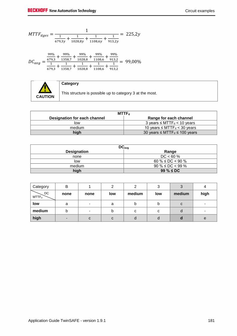
Circuit examples
Application Guide TwinSAFE - version 1.9.1 181
𝑀𝑇𝑇𝐹𝑑𝑔𝑒𝑠 =1
1
679,3𝑦+
1
1028,8𝑦+
1
1108,6𝑦+
1
913,2𝑦
= 225,2𝑦
𝐷𝐶𝑎𝑣𝑔 =
99%
679,3+
99%
1358,7+
99%
1028,8+
99%
1108,6+
99%
913,21
679,3+
1
1358,7+
1
1028,8+
1
1108,6+
1
913,2
= 99,00%
CAUTION
Category
This structure is possible up to category 3 at the most.
MTTFd Designation for each channel Range for each channel
low 3 years ≤ MTTFd < 10 years
medium 10 years ≤ MTTFd < 30 years
high 30 years ≤ MTTFd ≤ 100 years
DCavg Designation Range
none DC < 60 %
low 60 % ≤ DC < 90 %
medium 90 % ≤ DC < 99 %
high 99 % ≤ DC
Category B 1 2 2 3 3 4
DC MTTFd
none none low medium low medium high
low a - a b b c -
medium b - b c c d -
high - c c d d d e
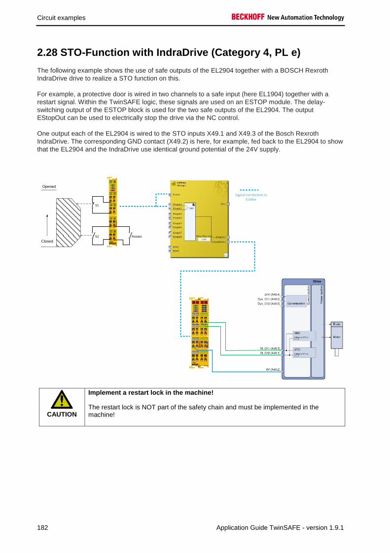
Circuit examples
182 Application Guide TwinSAFE - version 1.9.1
2.28 STO-Function with IndraDrive (Category 4, PL e)
The following example shows the use of safe outputs of the EL2904 together with a BOSCH Rexroth
IndraDrive drive to realize a STO function on this.
For example, a protective door is wired in two channels to a safe input (here EL1904) together with a
restart signal. Within the TwinSAFE logic, these signals are used on an ESTOP module. The delay-
switching output of the ESTOP block is used for the two safe outputs of the EL2904. The output
EStopOut can be used to electrically stop the drive via the NC control.
One output each of the EL2904 is wired to the STO inputs X49.1 and X49.3 of the Bosch Rexroth
IndraDrive. The corresponding GND contact (X49.2) is here, for example, fed back to the EL2904 to show
that the EL2904 and the IndraDrive use identical ground potential of the 24V supply.
Closed
Opened
S1
S2 Restart
logical connection in EL69xx
CAUTION
Implement a restart lock in the machine!
The restart lock is NOT part of the safety chain and must be implemented in the machine!

Circuit examples
Application Guide TwinSAFE - version 1.9.1 183
2.28.1 Parameters of the safe input and output terminals
EL1904
Parameter Value
Sensor test channel 1 active Yes
Sensor test channel 2 active Yes
Sensor test channel 3 active Yes
Sensor test channel 4 active Yes
Logic channel 1 and 2 Single Logic
Logic channel 3 and 4 Single Logic
EL2904
Parameter Value
Current measurement active No
Output test pulses active Yes
2.28.2 Block formation and safety loops
2.28.3 Safety function 1
EL1904 EL6900 EL2904
S1
S2
IndraDrive
2.28.4 Calculation
2.28.4.1 PFH / MTTFd /B10d – values
Component Value
EL1904 – PFH 1,11E-09
EL2904 – PFH 1,25E-09
EL6900 – PFH 1,03E-09
Bosch Rexroth IndraDrive1) - PFH 0,50E-09
Bosch Rexroth IndraDrive1) - MTTFD > 200 years
S1 – B10d 1.000.000
S2 – B10d 2.000.000
Days of operation (dop) 230
Hours of operation / day (hop) 16
Cycle time (minutes) (TZykus) 15 (4x per hour)
Lifetime (T1) 20 years = 175200 hours 1) Please refer to the Bosch Rexroth user documentation

Circuit examples
184 Application Guide TwinSAFE - version 1.9.1
2.28.4.2 Diagnostic Coverage DC
Component Value
S1/S2 with testing/plausibility DCavg=99%
EL2904 with testing DCavg=99%
Bosch Rexroth IndraDrive1) DCavg=99% 1) Please refer to the Bosch Rexroth user documentation
2.28.4.3 Calculation for safety function 1
Calculation of the PFH and MTTFd values from the B10d values:
off:
𝑛𝑜𝑝 =𝑑𝑜𝑝∗ℎ𝑜𝑝∗60
𝑇𝑍𝑦𝑘𝑙𝑢𝑠
and:
𝑀𝑇𝑇𝐹𝐷 =𝐵10𝑑
0,1 ∗ 𝑛𝑜𝑝
Inserting the values, this produces:
S1:
𝑛𝑜𝑝 =230∗16∗60
15= 14720
𝑀𝑇𝑇𝐹𝐷 =1000000
0,1∗14720= 679,3 y = 5951087 h
S2:
𝑛𝑜𝑝 =230∗16∗60
15= 14720
𝑀𝑇𝑇𝐹𝐷 =2000000
0,1∗14720= 1358,7 y = 11902174 h
and the assumption that S1 and S2 are each single-channel:
𝑀𝑇𝑇𝐹𝐷 =1
𝜆𝑑
produces for
𝑃𝐹𝐻 =0,1 ∗ 𝑛𝑜𝑝 ∗ (1 − 𝐷𝐶)
𝐵10𝑑
=1 − DC
MTTFD

Circuit examples
Application Guide TwinSAFE - version 1.9.1 185
S1:
𝑃𝐹𝐻 =1 − 0,99
679,3 ∗ 8760= 1,68E − 9
S2:
𝑃𝐹𝐻 =1 − 0,99
1358,7 ∗ 8760= 8,4E − 10
The following assumptions must now be made:
The door switches S1/S2 are always actuated in opposite directions. Since the switches have different
values, but the complete protective door switch consists of a combination of normally closed and normally
open contacts and both switches must function, the poorer of the two values (S1) can be taken for the
combination!
There is a coupling coefficient between the components that are connected via two channels. Examples
are temperature, EMC, voltage peaks or signals between these components. This is assumed to be the
worst-case estimation, where ß =10%. EN 62061 contains tables (Table F.1 criteria for the determination
of the CCF and Table F.2 estimation of the CCF factor (β)) with which this β factor can be determined
exactly.
Further, it is assumed that all usual measures have been taken to prevent both channels failing unsafely
at the same time due to an error (e.g. overcurrent through relay contacts, overtemperature in the control
cabinet).
This produces for the calculation of the PFH value for safety function 1:
𝑃𝐹𝐻𝑔𝑒𝑠 = 𝛽 ∗𝑃𝐹𝐻(𝑆1) + 𝑃𝐹𝐻(𝑆2)
2+(1 − 𝛽)2 ∗ (𝑃𝐹𝐻(𝑆1) ∗ 𝑃𝐹𝐻(𝑆2)) ∗ 𝑇1 + 𝑃𝐹𝐻(𝐸𝐿1904) + 𝑃𝐹𝐻(𝐸𝐿6900)
+ 𝑃𝐹𝐻(𝐸𝐿2904) + 𝑃𝐹𝐻(𝐼𝑛𝑑𝑟𝑎𝐷𝑟𝑖𝑣𝑒)
Since the portion (1 − 𝛽)2 ∗ (𝑃𝐹𝐻(𝑆1) ∗ 𝑃𝐹𝐻(𝑆2)) ∗ 𝑇1 is smaller than the rest by the power of ten, it is
neglected in this and all further calculations for the purpose of simplification.
to:
𝑃𝐹𝐻𝑔𝑒𝑠 = 10% ∗1,68𝐸 − 09 + 8,40𝐸 − 10
2+ 1,11𝐸 − 9 + 1,03𝐸 − 9 + 1,25𝐸 − 9 + 0,50𝐸 − 9
𝑷𝑭𝑯𝒈𝒆𝒔 = 𝟒, 𝟎𝟏𝟔𝑬 − 𝟎𝟗
Note
Calculation according to EN 62061
According to EN 62061 table 3, this value corresponds to a SIL3.
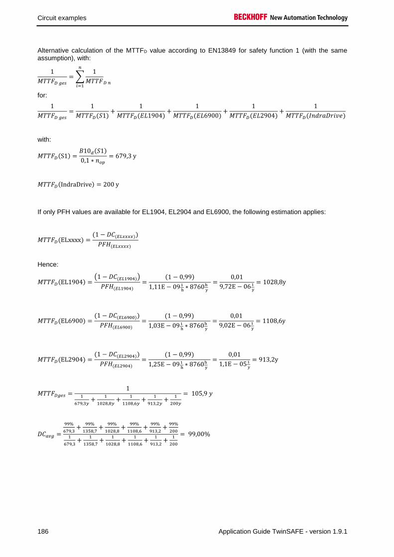
Circuit examples
186 Application Guide TwinSAFE - version 1.9.1
Alternative calculation of the MTTFD value according to EN13849 for safety function 1 (with the same assumption), with:
1
𝑀𝑇𝑇𝐹𝐷 𝑔𝑒𝑠
= ∑1
𝑀𝑇𝑇𝐹𝐷 𝑛
𝑛
𝑖=1
for:
1
𝑀𝑇𝑇𝐹𝐷 𝑔𝑒𝑠
=1
𝑀𝑇𝑇𝐹𝐷(𝑆1)+
1
𝑀𝑇𝑇𝐹𝐷(𝐸𝐿1904)+
1
𝑀𝑇𝑇𝐹𝐷(𝐸𝐿6900)+
1
𝑀𝑇𝑇𝐹𝐷(𝐸𝐿2904)+
1
𝑀𝑇𝑇𝐹𝐷(𝐼𝑛𝑑𝑟𝑎𝐷𝑟𝑖𝑣𝑒)
with:
𝑀𝑇𝑇𝐹𝐷(S1) =𝐵10𝑑(𝑆1)
0,1 ∗ 𝑛𝑜𝑝
= 679,3 y
𝑀𝑇𝑇𝐹𝐷(IndraDrive) = 200 y
If only PFH values are available for EL1904, EL2904 and EL6900, the following estimation applies:
𝑀𝑇𝑇𝐹𝐷(ELxxxx) =(1 − 𝐷𝐶(𝐸𝐿𝑥𝑥𝑥𝑥))
𝑃𝐹𝐻(𝐸𝐿𝑥𝑥𝑥𝑥)
Hence:
𝑀𝑇𝑇𝐹𝐷(EL1904) =(1 − 𝐷𝐶(𝐸𝐿1904))
𝑃𝐹𝐻(𝐸𝐿1904)
=(1 − 0,99)
1,11E − 091
h∗ 8760h
y
=0,01
9,72E − 061
y
= 1028,8y
𝑀𝑇𝑇𝐹𝐷(EL6900) =(1 − 𝐷𝐶(𝐸𝐿6900))
𝑃𝐹𝐻(𝐸𝐿6900) =
(1 − 0,99)
1,03E − 09 1
h∗ 8760h
y
=0,01
9,02E − 061
y
= 1108,6y
𝑀𝑇𝑇𝐹𝐷(EL2904) =(1 − 𝐷𝐶(𝐸𝐿2904))
𝑃𝐹𝐻(𝐸𝐿2904) =
(1 − 0,99)
1,25E − 09 1
h∗ 8760h
y
=0,01
1,1E − 051
y
= 913,2y
𝑀𝑇𝑇𝐹𝐷𝑔𝑒𝑠 =1
1
679,3𝑦+
1
1028,8𝑦+
1
1108,6𝑦+
1
913,2𝑦+
1
200𝑦
= 105,9 𝑦
𝐷𝐶𝑎𝑣𝑔 =
99%
679,3+
99%
1358,7+
99%
1028,8+
99%
1108,6+
99%
913,2+
99%
2001
679,3+
1
1358,7+
1
1028,8+
1
1108,6+
1
913,2+
1
200
= 99,00%

Circuit examples
Application Guide TwinSAFE - version 1.9.1 187
Note
Category
This structure is possible up to category 4 at the most.
MTTFd Designation for each channel Range for each channel
low 3 years ≤ MTTFd < 10 years
medium 10 years ≤ MTTFd < 30 years
high 30 years ≤ MTTFd ≤ 100 years
DCavg Designation Range
none DC < 60 %
low 60 % ≤ DC < 90 %
medium 90 % ≤ DC < 99 %
high 99 % ≤ DC
Category B 1 2 2 3 3 4
DC MTTFd
none none low medium low medium high
low a - a b b c -
medium b - b c c d -
high - c c d d d e
Safety integrity level according to Tab. 3 EN62061 Safety integrity level Probability of a dangerous failure per hour
(PFHD)
3 ≥ 10-8 to < 10-7
2 ≥ 10-7 to < 10-6
1 ≥ 10-6 to < 10-5

Circuit examples
188 Application Guide TwinSAFE - version 1.9.1
2.28.5 Technical Note from company Bosch Rexroth AG
This technical note is right now only available in German language. Please contact Bosch Rexroth AG in
case you need an English translation.

Circuit examples
Application Guide TwinSAFE - version 1.9.1 189

Circuit examples
190 Application Guide TwinSAFE - version 1.9.1

Circuit examples
Application Guide TwinSAFE - version 1.9.1 191
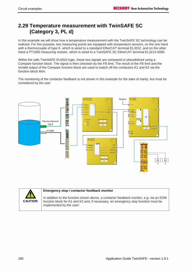
Circuit examples
192 Application Guide TwinSAFE - version 1.9.1
2.29 Temperature measurement with TwinSAFE SC (Category 3, PL d)
In this example we will show how a temperature measurement with the TwinSAFE SC technology can be
realized. For this purpose, two measuring points are equipped with temperature sensors, on the one hand
with a thermocouple of type K, which is wired to a standard EtherCAT terminal EL3312, and on the other
hand a PT1000 measuring resistor, which is wired to a TwinSAFE SC EtherCAT terminal EL3214-0090.
Within the safe TwinSAFE EL6910 logic, these two signals are compared or plausibilized using a
Compare function block. The signal is then checked via the FB limit. The result of the FB limit and the
IsValid output of the Compare function block are used to switch off the contactors K1 and K2 via the
function block Mon.
The monitoring of the contactor feedback is not shown in this example for the sake of clarity, but must be
considered by the user
Thermo-Element Typ K
PT1000
K1 K2
Restart
CAUTION
Emergency stop / contactor feedback monitor
In addition to the function shown above, a contactor feedback monitor, e.g. via an EDM function block for K1 and K2 and, if necessary, an emergency stop function must be implemented by the user!

Circuit examples
Application Guide TwinSAFE - version 1.9.1 193
2.29.1 Diagram of the structure
PT1000 EL3214-0090
PCBlackChannelTemperature
ActuatorEL2904EL6910
Thermo couple Type K
Standard FieldbusTemperature
EL3312
2.29.2 Structure and diagnosis
The read signals from the two measuring points are standard signals using a different technology. At least
one signal is transmitted via the TwinSAFE SC technology to the safe TwinSAFE logic so that
falsifications of this signal in the PC or on the transmission path are detected. The check for equality of
these two signals, within the permissible tolerances, is performed in the safe TwinSAFE logic.
The individual fault assumptions and associated expectations are listed in the following FMEA table
2.29.3 FMEA
Error assumption Expectations Checked
Temperature value over
standard fieldbus itself freezes
Detected via the second value and the plausibility check
in the EL6910.
Temperature value over
TwinSAFE SC communication
freezes
Detected by the watchdog within the TwinSAFE SC
communication and by the plausibility check in the
EL6910.
Temperature values are copied
in succession in the standard
PLC
A corrupt value within the TwinSAFE SC communication
results in an invalid CRC inside the telegram and thus
the immediate switch-off of the group and the outputs
Temperature value via the
standard fieldbus is corrupted
Detected via the second value and the plausibility check
in the EL6910.
There is no longer any
connection between the sensor
and the EtherCAT terminal
Detected within the EL6910 via the plausibility check
with the second temperature value.
PT1000 supplies an incorrect
temperature value
Detected within the EL6910 via the plausibility check
with the second temperature value.
Thermocouple supplies an
incorrect temperature value
Detected within the EL6910 via the plausibility check
with the second temperature value.
Communication error 61784-3
for standard communication:
Corruption
Is detected via the plausibility check of the temperature
values and via the TwinSAFE SC communication within
the EL6910.
Communication error 61784-3
for standard communication:
Unintentional repetition
Is detected via the plausibility check of the temperature
values and via the TwinSAFE SC communication within
the EL6910.

Circuit examples
194 Application Guide TwinSAFE - version 1.9.1
Error assumption Expectations Checked
Communication error 61784-3
for standard communication:
Wrong sequence
Is detected via the plausibility check of the temperature
values and via the TwinSAFE SC communication within
the EL6910.
Communication error 61784-3
for standard communication:
Loss
Is detected via the plausibility check of the temperature
values and via the TwinSAFE SC communication within
the EL6910.
Communication error 61784-3
for standard communication:
Unacceptable delay
Is detected via the plausibility check of the temperature
values and via the TwinSAFE SC communication within
the EL6910.
Communication error 61784-3
for standard communication:
Insertion
Is detected via the plausibility check of the temperature
values and via the TwinSAFE SC communication within
the EL6910.
Communication error 61784-3
for standard communication:
Masquerading
not relevant for standard, only for safety communication.
Communication error 61784-3
for standard communication:
Addressing
Is detected via the plausibility check of the temperature
values and via the TwinSAFE SC communication within
the EL6910.
Communication error for
standard communication:
Recurrent memory errors in
switches
Is detected via the plausibility check of the temperature
values and via the TwinSAFE SC communication within
the EL6910.
2.29.3.1 Note about TwinSAFE SC communication:
The TwinSAFE SC communication uses the identical mechanisms for error detection as the Safety-over-
EtherCAT communication, the difference being that a different polynomial is used to calculate the
checksum. This polynomial is sufficiently independent of the polynomial used for Safety-over-EtherCAT.
The identical mechanisms are active, such as the black channel principle (bit error probability 10-2).
The quality of the data transmission is not crucial, because ultimately all transmission errors are detected
via the comparison in the safe logic, since this would lead to inequality.

Circuit examples
Application Guide TwinSAFE - version 1.9.1 195
2.29.4 Parameters of the safe output terminal
EL2904
Parameter Value
Current measurement active No
Output test pulses active Yes
2.29.5 Block formation and safety loops
2.29.5.1 Safety function 1
EL3214-0090
EL3312
EL6910 EL2904
K1
K2Thermo couple type K
PT1000
Input1
Input2
2.29.6 Calculation
2.29.6.1 PFH / MTTFD /B10D – values
Component Value
EL2904 – PFH 1,25E-09
EL6910 – PFH 1,79E-09
PT1000 – MTTFD 7.618 a (acc. to table C.5 EN ISO 13849-1:2015)
Thermocouple Type K – FIT 1900 (Amount of errors in 109 hours)
EL3214-0090 - MTBF 890.000
EL3312 - MTBF 1.661.253
K1 – B10D 1.300.000
K2 – B10D 1.300.000
Days of operation (dop) 230
Hours of operation / day (hop) 16
Cycle time (minutes) (TZyklus) 10080 (1x per week)
Lifetime (T1) 20 years = 175200 hours

Circuit examples
196 Application Guide TwinSAFE - version 1.9.1
2.29.6.2 Diagnostic Coverage DC
Component Value
Temperature values over TwinSAFE SC and
plausibility check inside the logic
DCavg=90% (Alternatively in calculation: 99%)
K1/K2 with EDM monitoring (actuation 1x per
week and evaluation of all rising and falling
edges with monitoring over time) with testing of
the individual channels
DCavg=99%
2.29.6.3 Calculation safety function 1
For clarification, the safety parameter is calculated according to both EN62061 and EN13849. Calculation according to one standard is sufficient in practice.
Calculation of the PFH and MTTFd values from the B10d values:
From:
𝑛𝑜𝑝 =𝑑𝑜𝑝∗ℎ𝑜𝑝∗60
𝑇𝑍𝑦𝑘𝑙𝑢𝑠
and:
𝑀𝑇𝑇𝐹𝐷 =𝐵10𝐷
0,1 ∗ 𝑛𝑜𝑝
Calculation of the PFH and MTTFD values from the MTBF values:
Note: Repair times can be neglected, therefore the following applies:
𝑀𝑇𝑇𝐹𝐷 = 2 ∗ 𝑀𝑇𝐵𝐹
𝑀𝑇𝑇𝐹𝐷 =1
𝜆𝐷
With:
𝜆𝐷 ≈0,1
𝑇10𝐷
=0,1 ∗ 𝑛𝑜𝑝
𝐵10𝐷
results in:
𝑃𝐹𝐻 =0,1 ∗ 𝑛𝑜𝑝 ∗ (1 − 𝐷𝐶)
𝐵10𝐷
=1 − DC
MTTFD

Circuit examples
Application Guide TwinSAFE - version 1.9.1 197
Inserting the values, this produces:
PT1000 𝑀𝑇𝑇𝐹𝐷 = 7618 𝑦 = 66.733.680 ℎ
𝑃𝐹𝐻 =1 − DC
MTTFD
=1 − 0,9
66.733.680 ℎ= 1,50E − 09
EL3214-0090 𝑀𝑇𝑇𝐹𝐷 = 2 ∗ 𝑀𝑇𝐵𝐹 = 2 ∗ 890.000 ℎ = 1.780.000 ℎ = 203 𝑦
𝑃𝐹𝐻 =1 − DC
MTTFD
=1 − 0,9
1.780.000 ℎ= 5,62E − 08
Input 1 subsystem
𝑃𝐹𝐻(𝐼𝑛𝑝𝑢𝑡1) = 𝑃𝐹𝐻(𝑃𝑇1000) + 𝑃𝐹𝐻(𝐸𝐿3214−0090) = 1,5𝐸 − 09 + 5,62𝐸 − 08 = 5,77𝐸 − 08
Thermo couple
𝑀𝑇𝑇𝐹𝐷 =1
𝜆𝐷
=1
1900 𝐹𝐼𝑇∗ 109ℎ = 526.315 ℎ = 60 𝑦
𝑃𝐹𝐻 =1 − DC
MTTFD
=1 − 0,9
526.315 ℎ= 19,0E − 08
EL3312 𝑀𝑇𝑇𝐹𝐷 = 2 ∗ 𝑀𝑇𝐵𝐹 = 2 ∗ 1.661.253 ℎ = 3.322.506 ℎ = 379 𝑦
𝑃𝐹𝐻 =1 − DC
MTTFD
=1 − 0,9
3.322.506 ℎ= 3,0E − 08
Input 2 subsystem
𝑃𝐹𝐻(𝐼𝑛𝑝𝑢𝑡2) = 𝑃𝐹𝐻(𝑇ℎ𝑒𝑟𝑚𝑜𝑐𝑜𝑢𝑝𝑙𝑒) + 𝑃𝐹𝐻(𝐸𝐿3312) = 19,0𝐸 − 08 + 3,0𝐸 − 08 = 22,0𝐸 − 08
K1/K2
𝑛𝑜𝑝 =230∗16∗60
10080= 21,90
𝑀𝑇𝑇𝐹𝐷 =1300000
0,1 ∗ 21,90= 593.607 𝑦 = 5.199.997.320 ℎ
and the assumption that K1 and K2 are each single-channel:
K1/K2: Actuation 1x per week and direct feedback
𝑃𝐹𝐻 =1 − 0,99
593607,3 ∗ 8760= 1,92E − 12

Circuit examples
198 Application Guide TwinSAFE - version 1.9.1
The following assumptions must now be made:
Relays K1 and K2 are both connected to the safety function. The non-functioning of a relay does not lead
to a dangerous situation, but it is discovered by the feedback. Furthermore, the B10d values for K1 and
K2 are identical.
The input signals from PT1000 with EL3214-0090 and thermocouple with EL3312 have different
measuring methods, provide both temperature values and are both involved in the safety function. A non-
functioning of a channel does not lead to a dangerous situation, but is detected by the comparison of the
two values in the TwinSAFE logic and leads to a shutdown.
There is a coupling coefficient between the components that are connected via two channels. Examples
are temperature, EMC, voltage peaks or signals between these components. This is assumed to be the
worst-case estimation, where ß =10%. EN 62061 contains tables (Table F.1 criteria for the determination
of the CCF and Table F.2 estimation of the CCF factor (β)) with which this β factor can be determined
exactly. For the input subsystem an estimated value of 2% can be achieved by processing the table to
calculate the β factor. In the following calculation, the worst case is assumed to be 10%.
Further, it is assumed that all usual measures have been taken to prevent both channels failing unsafely
at the same time due to an error (e.g. overcurrent through relay contacts, overtemperature in the control
cabinet)
This produces for the calculation of the PFH value for safety function 1:
𝑃𝐹𝐻𝑔𝑒𝑠 = 𝛽 ∗(𝑃𝐹𝐻(𝐼𝑛𝑝𝑢𝑡1) + 𝑃𝐹𝐻(𝐼𝑛𝑝𝑢𝑡2))
2+ (1 − 𝛽)2 ∗ (𝑃𝐹𝐻(𝐼𝑛𝑝𝑢𝑡1) ∗ 𝑃𝐹𝐻(𝐼𝑛𝑝𝑢𝑡2)) ∗ 𝑇1 + 𝑃𝐹𝐻(𝐸𝐿6910)
+ 𝑃𝐹𝐻(𝐸𝐿2904) + 𝛽 ∗𝑃𝐹𝐻(𝐾1) + 𝑃𝐹𝐻(𝐾2)
2+ (1 − 𝛽)2 ∗ (𝑃𝐹𝐻(𝐾1) ∗ 𝑃𝐹𝐻(𝐾2)) ∗ 𝑇1
Since the portions (1 − 𝛽)2 ∗ (𝑃𝐹𝐻(𝐾1) ∗ 𝑃𝐹𝐻(𝐾2)) ∗ 𝑇1 and (1 − 𝛽)2 ∗ (𝑃𝐹𝐻(𝐼𝑛𝑝𝑢𝑡1) ∗ 𝑃𝐹𝐻(𝐼𝑛𝑝𝑢𝑡2)) ∗ 𝑇1 are
smaller than the rest by the power of ten, they are neglected in this and all further calculations for the
purpose of simplification.
to:
𝑃𝐹𝐻𝑔𝑒𝑠 = 10% ∗5,77𝐸 − 08 + 22,0𝐸 − 08
2+ 1,79𝐸 − 9 + 1,25𝐸 − 9 + 10% ∗
1,92𝐸 − 12 + 1,92𝐸 − 12
2= 1,3885𝐸 − 08 + 1,79𝐸 − 09 + 1,25𝐸 − 9 + 1,92𝐸 − 13
𝑷𝑭𝑯𝒈𝒆𝒔 = 𝟏, 𝟔𝟗𝟑𝑬 − 𝟎𝟖
Note
EN 62061
In accordance with EN 62061, the input subsystem is evaluated with an SFF or a DC of 90%. This restricts the achievable SIL value according to table 5 of EN 62061 to a maximum SIL 2.

Circuit examples
Application Guide TwinSAFE - version 1.9.1 199
Alternative calculation of the MTTFd value according to EN13849 for safety function 1 (with the same assumption), with:
1
𝑀𝑇𝑇𝐹𝐷 𝑔𝑒𝑠
= ∑1
𝑀𝑇𝑇𝐹𝐷 𝑛
𝑛
𝑖=1
From the input subsystem, the poorer value is taken:
1
𝑀𝑇𝑇𝐹𝐷 𝑔𝑒𝑠
=1
𝑀𝑇𝑇𝐹𝐷 (𝑇ℎ𝑒𝑟𝑚𝑜𝑐𝑜𝑢𝑝𝑙𝑒)
+1
𝑀𝑇𝑇𝐹𝐷 (𝐸𝐿3312)
+1
𝑀𝑇𝑇𝐹𝐷 (𝐸𝐿6910)
+1
𝑀𝑇𝑇𝐹𝐷 (𝐸𝐿2904)
+1
𝑀𝑇𝑇𝐹𝐷 (𝐾1)
If only PFH values are available for EL2904 and EL6910, the following estimation applies:
𝑀𝑇𝑇𝐹𝐷 (ELxxxx)=
(1 − 𝐷𝐶(𝐸𝐿𝑥𝑥𝑥))
𝑃𝐹𝐻(𝐸𝐿𝑥𝑥𝑥)
Hence:
𝑀𝑇𝑇𝐹𝐷 (EL6910)=
(1 − 𝐷𝐶(𝐸𝐿6910))
𝑃𝐹𝐻(𝐸𝐿6910) =
(1 − 0,99)
1,79E − 09 1
h∗ 8760h
y
=0,01
15,68E − 061
y
= 637 y
𝑀𝑇𝑇𝐹𝐷 (EL2904)=
(1 − 𝐷𝐶(𝐸𝐿2904))
𝑃𝐹𝐻(𝐸𝐿2904) =
(1 − 0,99)
1,25E − 09 1
h∗ 8760h
y
=0,01
1,1E − 051
y
= 913 y
𝑀𝑇𝑇𝐹𝐷 𝑔𝑒𝑠 =1
1
60+
1
379+
1
637+
1
913+
1
593.607
= 45,5 𝑦
𝐷𝐶𝑎𝑣𝑔
=
𝐷𝐶
𝑀𝑇𝑇𝐹𝐷(𝑃𝑇1000)
+𝐷𝐶
𝑀𝑇𝑇𝐹𝐷(𝐸𝐿3214)
+𝐷𝐶
𝑀𝑇𝑇𝐹𝐷(𝑇𝐶)
+𝐷𝐶
𝑀𝑇𝑇𝐹𝐷(𝐸𝐿3312)
+𝐷𝐶
𝑀𝑇𝑇𝐹𝐷(𝐸𝐿6910)
+𝐷𝐶
𝑀𝑇𝑇𝐹𝐷(𝐸𝐿2904)
+𝐷𝐶
𝑀𝑇𝑇𝐹𝐷(𝐾1)
+𝐷𝐶
𝑀𝑇𝑇𝐹𝐷(𝐾2)
1
𝑀𝑇𝑇𝐹𝐷(𝑃𝑇1000)
+1
𝑀𝑇𝑇𝐹𝐷(𝐸𝐿3214)
+1
𝑀𝑇𝑇𝐹𝐷(𝑇𝐶)
+1
𝑀𝑇𝑇𝐹𝐷(𝐸𝐿3312)
+1
𝑀𝑇𝑇𝐹𝐷(𝐸𝐿6910)
+1
𝑀𝑇𝑇𝐹𝐷(𝐸𝐿2904)
+1
𝑀𝑇𝑇𝐹𝐷(𝐾1)
+1
𝑀𝑇𝑇𝐹𝐷(𝐾2)
Used with DC=90%
𝐷𝐶𝑎𝑣𝑔 =
0,9
7.618+
0,9
203+
0,9
60+
0,9
379+
0,99
637+
0,99
913+
0,99
593607+
0,99
5936071
7.618+
1
203+
1
60+
1
379+
1
637+
1
913+
1
593607+
1
593607
=0,0246
0,0270= 91,11%
Alternatively with DC=99%
𝐷𝐶𝑎𝑣𝑔 =
0,99
7.618+
0,99
203+
0,99
60+
0,99
379+
0,99
637+
0,99
913+
0,99
593607+
0,99
5936071
7.618+
1
203+
1
60+
1
379+
1
637+
1
913+
1
593607+
1
593607
=0,0268
0,0270= 99,26%

Circuit examples
200 Application Guide TwinSAFE - version 1.9.1
CAUTION
Category
This structure is possible up to category 3 at the most.
DC=90% for the input subsystem
MTTFd Designation for each channel Range for each channel
low 3 years ≤ MTTFd < 10 years
medium 10 years ≤ MTTFd < 30 years
high 30 years ≤ MTTFd ≤ 100 years
DCavg Designation Range
none DC < 60 %
low 60 % ≤ DC < 90 %
medium 90 % ≤ DC < 99 %
high 99 % ≤ DC
For practical usability, the number of the ranges was limited to four. An accuracy of 5% is assumed for
the limit values shown in this table.
Category B 1 2 2 3 3 4
DC
MTTFd none none low medium low medium high
low a - a b b c -
medium b - b c c d -
high - c c d d d e

Circuit examples
Application Guide TwinSAFE - version 1.9.1 201
Alternatively with DC=99% for the input subsystem
MTTFd Designation for each channel Range for each channel
low 3 years ≤ MTTFd < 10 years
medium 10 years ≤ MTTFd < 30 years
high 30 years ≤ MTTFd ≤ 100 years
DCavg Designation Range
none DC < 60 %
low 60 % ≤ DC < 90 %
medium 90 % ≤ DC < 99 %
high 99 % ≤ DC
For practical usability, the number of the ranges was limited to four. An accuracy of 5% is assumed for
the limit values shown in this table.
Category B 1 2 2 3 3 4
DC
MTTFd none none low medium low medium high
low a - a b b c -
medium b - b c c d -
high - c c d d d e
Safety integrity level according to Tab. 3 EN62061 Safety integrity level Probability of a dangerous failure per hour
(PFHD)
3 ≥ 10-8 to < 10-7
2 ≥ 10-7 to < 10-6
1 ≥ 10-6 to < 10-5

Circuit examples
202 Application Guide TwinSAFE - version 1.9.1
2.30 Level measurement with TwinSAFE SC (Category 3, PL d)
In this example we will show how a level measurement with the TwinSAFE SC technology can be
realized. Two different measurement methods are used for this purpose. On the one hand an ultrasonic
sensor with a 0 - 10 V interface, which is wired to a TwinSAFE SC EtherCAT box EP3174-0092 is used,
and on the other hand a level probe with 4-20 mA interface, which is wired to a standard EtherCAT
terminal EL3152.
Within the safe TwinSAFE EL6910 logic, these two signals are compared or plausibilized using a
Compare function block. The signal from EP3174-0092 is previously scaled via the scale function block
so that the two signals have an identical value range. The signal is then checked via the FB limit. The
result of the FB limit and the IsValid output of the Compare function block are used to switch off the
contactors K1 and K2 via the function block Mon. In addition, the StuckAtError output of the scale function
block can also be placed on a Mon input. This means that a freezing of the signal can be detected.
The monitoring of the contactor feedback is not shown in this example for the sake of clarity, but must be
considered by the user
4..20 mA
0..10 V
K1 K2
Restart
CAUTION
Emergency stop / contactor feedback monitor
In addition to the function shown above, a contactor feedback monitor, e.g. via an EDM function block for K1 and K2 and, if necessary, an emergency stop function must be implemented by the user!

Circuit examples
Application Guide TwinSAFE - version 1.9.1 203
2.30.1 Diagram of the structure
Ultrasonic sensor0..10 V
EP3174-0092
PCBlackChannel
LevelActuatorEL2904EL6910
Level probe4..20 mA
Standard FieldbusLevel
EL3152
2.30.2 Structure and diagnosis
The read signals from the two measuring points are standard signals using a different technology. At least
one signal is transmitted via the TwinSAFE SC technology to the safe TwinSAFE logic so that
falsifications of this signal in the PC or on the transmission path are detected. The check for equality of
these two signals, within the permissible tolerances, is performed in the safe TwinSAFE logic.
The individual fault assumptions and associated expectations are listed in the following FMEA table
2.30.3 FMEA
Error assumption Expectations Checked
Level value over standard
fieldbus itself freezes
Detected via the second value and the plausibility check
in the EL6910.
Level value over TwinSAFE SC
communication freezes
Detected by the watchdog within the TwinSAFE SC
communication and by the plausibility check in the
EL6910.
Level values are copied in
succession in the standard PLC
A corrupt value within the TwinSAFE SC communication
results in an invalid CRC inside the telegram and thus
the immediate switch-off of the group and the outputs
Level value via the standard
fieldbus is corrupted
Detected via the second value and the plausibility check
in the EL6910.
There is no longer any
connection between the sensor
and the EtherCAT terminal
Detected within the EL6910 via the plausibility check
with the second level value.
Ultrasonic sensor supplies an
incorrect level value
Detected within the EL6910 via the plausibility check
with the second level value.
Level probe supplies an
incorrect level value
Detected within the EL6910 via the plausibility check
with the second level value.
Communication error 61784-3
for standard communication:
Corruption
Is detected via the plausibility check of the level values
and via the TwinSAFE SC communication within the
EL6910.
Communication error 61784-3
for standard communication:
Unintentional repetition
Is detected via the plausibility check of the level values
and via the TwinSAFE SC communication within the
EL6910.
Communication error 61784-3
for standard communication:
Wrong sequence
Is detected via the plausibility check of the level values
and via the TwinSAFE SC communication within the
EL6910.

Circuit examples
204 Application Guide TwinSAFE - version 1.9.1
Error assumption Expectations Checked
Communication error 61784-3
for standard communication:
Loss
Is detected via the plausibility check of the level values
and via the TwinSAFE SC communication within the
EL6910.
Communication error 61784-3
for standard communication:
Unacceptable delay
Is detected via the plausibility check of the level values
and via the TwinSAFE SC communication within the
EL6910.
Communication error 61784-3
for standard communication:
Insertion
Is detected via the plausibility check of the level values
and via the TwinSAFE SC communication within the
EL6910.
Communication error 61784-3
for standard communication:
Masquerading
not relevant for standard, only for safety communication.
Communication error 61784-3
for standard communication:
Addressing
Is detected via the plausibility check of the level values
and via the TwinSAFE SC communication within the
EL6910.
Communication error for
standard communication:
Recurrent memory errors in
switches
Is detected via the plausibility check of the level values
and via the TwinSAFE SC communication within the
EL6910.
2.30.3.1 Note about TwinSAFE SC communication:
The TwinSAFE SC communication uses the identical mechanisms for error detection as the Safety-over-
EtherCAT communication, the difference being that a different polynomial is used to calculate the
checksum. This polynomial is sufficiently independent of the polynomial used for Safety-over-EtherCAT.
The identical mechanisms are active, such as the black channel principle (bit error probability 10-2).
The quality of the data transmission is not crucial, because ultimately all transmission errors are detected
via the comparison in the safe logic, since this would lead to inequality.

Circuit examples
Application Guide TwinSAFE - version 1.9.1 205
2.30.4 Parameters of the safe output terminal
EL2904
Parameter Value
Current measurement active No
Output test pulses active Yes
2.30.5 Block formation and safety-loops
2.30.5.1 Safety function 1
EP3174-0092
EL3152
EL6910 EL2904
K1
K2level probe
Ultrasonicsensor
Input1
Input2
2.30.6 Calculation
2.30.6.1 PFH / MTTFD /B10D – values
Component Value
EL2904 – PFH 1,25E-09
EL6910 – PFH 1,79E-09
Ultrasonic sensor – MTBF 195 a (1.708.200 h)
Level probe – MTTF 732 a (6.412.320 h)
EP3174-0092 - MTBF 600.000 h
EL3152 - MTBF 2.507.303 h
K1 – B10D 1.300.000 h
K2 – B10D 1.300.000 h
Days of operation (dop) 230
Hours of operation / day (hop) 16
Cycle time (minutes) (TZyklus) 10080 (1x per week)
Lifetime (T1) 20 years = 175200 hours
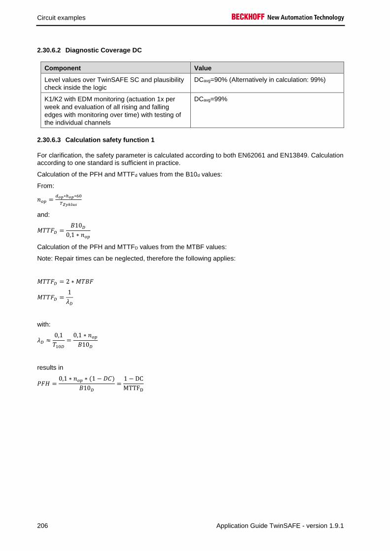
Circuit examples
206 Application Guide TwinSAFE - version 1.9.1
2.30.6.2 Diagnostic Coverage DC
Component Value
Level values over TwinSAFE SC and plausibility
check inside the logic
DCavg=90% (Alternatively in calculation: 99%)
K1/K2 with EDM monitoring (actuation 1x per
week and evaluation of all rising and falling
edges with monitoring over time) with testing of
the individual channels
DCavg=99%
2.30.6.3 Calculation safety function 1
For clarification, the safety parameter is calculated according to both EN62061 and EN13849. Calculation according to one standard is sufficient in practice.
Calculation of the PFH and MTTFd values from the B10d values:
From:
𝑛𝑜𝑝 =𝑑𝑜𝑝∗ℎ𝑜𝑝∗60
𝑇𝑍𝑦𝑘𝑙𝑢𝑠
and:
𝑀𝑇𝑇𝐹𝐷 =𝐵10𝐷
0,1 ∗ 𝑛𝑜𝑝
Calculation of the PFH and MTTFD values from the MTBF values:
Note: Repair times can be neglected, therefore the following applies:
𝑀𝑇𝑇𝐹𝐷 = 2 ∗ 𝑀𝑇𝐵𝐹
𝑀𝑇𝑇𝐹𝐷 =1
𝜆𝐷
with:
𝜆𝐷 ≈0,1
𝑇10𝐷
=0,1 ∗ 𝑛𝑜𝑝
𝐵10𝐷
results in
𝑃𝐹𝐻 =0,1 ∗ 𝑛𝑜𝑝 ∗ (1 − 𝐷𝐶)
𝐵10𝐷
=1 − DC
MTTFD

Circuit examples
Application Guide TwinSAFE - version 1.9.1 207
Inserting the values, this produces:
Ultrasonic sensor 𝑀𝑇𝑇𝐹𝐷 = 2 ∗ MTBF = 2 ∗ 195 𝑦 = 390 𝑦 = 3.416.400 ℎ
𝑃𝐹𝐻 =1 − DC
MTTFD
=1 − 0,9
3.416.400 ℎ= 2,93E − 08
EP3174-0092 𝑀𝑇𝑇𝐹𝐷 = 2 ∗ 𝑀𝑇𝐵𝐹 = 2 ∗ 600.000 ℎ = 1.200.000 ℎ = 136 𝑦
𝑃𝐹𝐻 =1 − DC
MTTFD
=1 − 0,9
1.200.000 ℎ= 8,33E − 08
Input 1 subsystem
𝑃𝐹𝐻(𝐼𝑛𝑝𝑢𝑡1) = 𝑃𝐹𝐻(𝑈𝑙𝑡𝑟𝑎𝑠𝑜𝑛𝑖𝑐) + 𝑃𝐹𝐻(𝐸𝑃3174−0092) = 2,93𝐸 − 08 + 8,33𝐸 − 08 = 11,26𝐸 − 08
Level probe 𝑀𝑇𝑇𝐹𝐷 = 2 ∗ MTTF = 2 ∗ 732 𝑦 = 1.464 𝑦 = 12.824.640 ℎ
𝑃𝐹𝐻 =1 − DC
MTTFD
=1 − 0,9
12.824.640 ℎ= 7,79E − 09
EL3152 𝑀𝑇𝑇𝐹𝐷 = 2 ∗ 𝑀𝑇𝐵𝐹 = 2 ∗ 2.507.303 ℎ = 5.014.606 ℎ = 572 𝑦
𝑃𝐹𝐻 =1 − DC
MTTFD
=1 − 0,9
5.014.606 ℎ= 1,99E − 08
Input 2 subsystem
𝑃𝐹𝐻(𝐼𝑛𝑝𝑢𝑡2) = 𝑃𝐹𝐻(𝑙𝑒𝑣𝑒𝑙 𝑝𝑟𝑜𝑏𝑒) + 𝑃𝐹𝐻(𝐸𝐿3152) = 7,79𝐸 − 09 + 1,99𝐸 − 08 = 2,77𝐸 − 08
K1/K2
𝑛𝑜𝑝 =230∗16∗60
10080= 21,90
𝑀𝑇𝑇𝐹𝐷 =1300000
0,1 ∗ 21,90= 593.607 𝑦 = 5.199.997.320 ℎ
and the assumption that K1 and K2 are each single-channel:
K1/K2: Actuation 1x per week and direct feedback
𝑃𝐹𝐻 =1 − 0,99
593607,3 ∗ 8760= 1,92E − 12

Circuit examples
208 Application Guide TwinSAFE - version 1.9.1
The following assumptions must now be made:
Relays K1 and K2 are both connected to the safety function. The non-functioning of a relay does not lead
to a dangerous situation, but it is discovered by the feedback. Furthermore, the B10d values for K1 and
K2 are identical.
The input signals from ultrasonic sensor with EP3174-0092 and level probe with EL3152 have different
measuring methods, provide both level values and are both involved in the safety function. A non-
functioning of a channel does not lead to a dangerous situation, but is detected by the comparison of the
two values in the TwinSAFE logic and leads to a shutdown.
There is a coupling coefficient between the components that are connected via two channels. Examples
are temperature, EMC, voltage peaks or signals between these components. This is assumed to be the
worst-case estimation, where ß =10%. EN 62061 contains tables (Table F.1 criteria for the determination
of the CCF and Table F.2 estimation of the CCF factor (β)) with which this β factor can be determined
exactly. For the input subsystem an estimated value of 2% can be achieved by processing the table to
calculate the β factor. In the following calculation, the worst case is assumed to be 10%.
Further, it is assumed that all usual measures have been taken to prevent both channels failing unsafely
at the same time due to an error (e.g. overcurrent through relay contacts, overtemperature in the control
cabinet)
This produces for the calculation of the PFH value for safety function 1:
𝑃𝐹𝐻𝑔𝑒𝑠 = 𝛽 ∗(𝑃𝐹𝐻(𝐼𝑛𝑝𝑢𝑡1) + 𝑃𝐹𝐻(𝐼𝑛𝑝𝑢𝑡2))
2+ (1 − 𝛽)2 ∗ (𝑃𝐹𝐻(𝐼𝑛𝑝𝑢𝑡1) ∗ 𝑃𝐹𝐻(𝐼𝑛𝑝𝑢𝑡2)) ∗ 𝑇1 + 𝑃𝐹𝐻(𝐸𝐿6910)
+ 𝑃𝐹𝐻(𝐸𝐿2904) + 𝛽 ∗𝑃𝐹𝐻(𝐾1) + 𝑃𝐹𝐻(𝐾2)
2+ (1 − 𝛽)2 ∗ (𝑃𝐹𝐻(𝐾1) ∗ 𝑃𝐹𝐻(𝐾2)) ∗ 𝑇1
Since the portions (1 − 𝛽)2 ∗ (𝑃𝐹𝐻(𝐾1) ∗ 𝑃𝐹𝐻(𝐾2)) ∗ 𝑇1 and (1 − 𝛽)2 ∗ (𝑃𝐹𝐻(𝐼𝑛𝑝𝑢𝑡1) ∗ 𝑃𝐹𝐻(𝐼𝑛𝑝𝑢𝑡2)) ∗ 𝑇1 are
smaller than the rest by the power of ten, they are neglected in this and all further calculations for the
purpose of simplification.
to:
𝑃𝐹𝐻𝑔𝑒𝑠 = 10% ∗11,26𝐸 − 08 + 2,77𝐸 − 08
2+ 1,79𝐸 − 9 + 1,25𝐸 − 9 + 10% ∗
1,92𝐸 − 12 + 1,92𝐸 − 12
2= 7,015𝐸 − 09 + 1,79𝐸 − 09 + 1,25𝐸 − 9 + 1,92𝐸 − 13
𝑷𝑭𝑯𝒈𝒆𝒔 = 𝟏, 𝟎𝟎𝟓𝑬 − 𝟎𝟖
Note
EN 62061
In accordance with EN 62061, the input subsystem is evaluated with an SFF or a DC of 90%. This restricts the achievable SIL value according to table 5 of EN 62061 to a maximum SIL 2.

Circuit examples
Application Guide TwinSAFE - version 1.9.1 209
Alternative calculation of the MTTFd value according to EN13849 for safety function 1 (with the same assumption), with:
1
𝑀𝑇𝑇𝐹𝐷 𝑔𝑒𝑠
= ∑1
𝑀𝑇𝑇𝐹𝐷 𝑛
𝑛
𝑖=1
From the input subsystem, the poorer value is taken:
1
𝑀𝑇𝑇𝐹𝐷 𝑔𝑒𝑠
=1
𝑀𝑇𝑇𝐹𝐷 (𝑈𝑙𝑡𝑟𝑎𝑠𝑜𝑛𝑖𝑐 𝑠𝑒𝑛𝑠𝑜𝑟)
+1
𝑀𝑇𝑇𝐹𝐷 (𝐸𝑃3174−0092)
+1
𝑀𝑇𝑇𝐹𝐷 (𝐸𝐿6910)
+1
𝑀𝑇𝑇𝐹𝐷 (𝐸𝐿2904)
+1
𝑀𝑇𝑇𝐹𝐷 (𝐾1)
If only PFH values are available for EL2904 and EL6910, the following estimation applies:
𝑀𝑇𝑇𝐹𝐷 (ELxxxx)=
(1 − 𝐷𝐶(𝐸𝐿𝑥𝑥𝑥))
𝑃𝐹𝐻(𝐸𝐿𝑥𝑥𝑥)
Hence:
𝑀𝑇𝑇𝐹𝐷 (EL6910)=
(1 − 𝐷𝐶(𝐸𝐿6910))
𝑃𝐹𝐻(𝐸𝐿6910) =
(1 − 0,99)
1,79E − 09 1
h∗ 8760h
y
=0,01
15,68E − 061
y
= 637 y
𝑀𝑇𝑇𝐹𝐷 (EL2904)=
(1 − 𝐷𝐶(𝐸𝐿2904))
𝑃𝐹𝐻(𝐸𝐿2904) =
(1 − 0,99)
1,25E − 09 1
h∗ 8760h
y
=0,01
1,1E − 051
y
= 913 y
𝑀𝑇𝑇𝐹𝐷 𝑔𝑒𝑠 =1
1
390+
1
136+
1
637+
1
913+
1
593.607
= 79,46 𝑦
𝐷𝐶𝑎𝑣𝑔 =
𝐷𝐶
𝑀𝑇𝑇𝐹𝐷(𝑈𝑙𝑡𝑟𝑎𝑆𝑜𝑛𝑖𝑐)+
𝐷𝐶
𝑀𝑇𝑇𝐹𝐷(𝐸𝑃3174)+
𝐷𝐶
𝑀𝑇𝑇𝐹𝐷(𝑙𝑒𝑣𝑒𝑙 𝑝𝑟𝑜𝑏𝑒)+
𝐷𝐶
𝑀𝑇𝑇𝐹𝐷(𝐸𝐿3152)+
𝐷𝐶
𝑀𝑇𝑇𝐹𝐷(𝐸𝐿6910)+
𝐷𝐶
𝑀𝑇𝑇𝐹𝐷(𝐸𝐿2904)+
𝐷𝐶
𝑀𝑇𝑇𝐹𝐷(𝐾1)+
𝐷𝐶
𝑀𝑇𝑇𝐹𝐷(𝐾2)1
𝑀𝑇𝑇𝐹𝐷(𝑈𝑙𝑡𝑟𝑎𝑆𝑜𝑛𝑖𝑐)+
1
𝑀𝑇𝑇𝐹𝐷(𝐸𝑃3174)+
1
𝑀𝑇𝑇𝐹𝐷(𝑙𝑒𝑣𝑒𝑙 𝑝𝑟𝑜𝑏𝑒)+
1
𝑀𝑇𝑇𝐹𝐷(𝐸𝐿3152)+
1
𝑀𝑇𝑇𝐹𝐷(𝐸𝐿6910)+
1
𝑀𝑇𝑇𝐹𝐷(𝐸𝐿2904)+
1
𝑀𝑇𝑇𝐹𝐷(𝐾1)+
1
𝑀𝑇𝑇𝐹𝐷(𝐾2)
Used with DC=90%
𝐷𝐶𝑎𝑣𝑔 =
0,9
390+
0,9
136+
0,9
1464+
0,9
572+
0,99
637+
0,99
913+
0,99
593607+
0,99
5936071
390+
1
136+
1
1464+
1
572+
1
637+
1
913+
1
593607+
1
593607
=0,0137
0,0150= 91,33%
Alternatively with DC=99%
𝐷𝐶𝑎𝑣𝑔 =
0,99
390+
0,99
136+
0,99
1464+
0,99
572+
0,99
637+
0,99
913+
0,99
593607+
0,99
5936071
390+
1
136+
1
1464+
1
572+
1
637+
1
913+
1
593607+
1
593607
=0,01486
0,0150= 99,06%

Circuit examples
210 Application Guide TwinSAFE - version 1.9.1
CAUTION
Category
This structure is possible up to category 3 at the most.
DC=90% for the input subsystem
MTTFd Designation for each channel Range for each channel
low 3 years ≤ MTTFd < 10 years
medium 10 years ≤ MTTFd < 30 years
high 30 years ≤ MTTFd ≤ 100 years
DCavg Designation Range
none DC < 60 %
low 60 % ≤ DC < 90 %
medium 90 % ≤ DC < 99 %
high 99 % ≤ DC
For practical usability, the number of the ranges was limited to four. An accuracy of 5% is assumed for
the limit values shown in this table.
Category B 1 2 2 3 3 4
DC
MTTFd none none low medium low medium high
low a - a b b c -
medium b - b c c d -
high - c c d d d e

Circuit examples
Application Guide TwinSAFE - version 1.9.1 211
Alternatively with DC=99% for the input subsystem
MTTFd Designation for each channel Range for each channel
low 3 years ≤ MTTFd < 10 years
medium 10 years ≤ MTTFd < 30 years
high 30 years ≤ MTTFd ≤ 100 years
DCavg Designation Range
none DC < 60 %
low 60 % ≤ DC < 90 %
medium 90 % ≤ DC < 99 %
high 99 % ≤ DC
For practical usability, the number of the ranges was limited to four. An accuracy of 5% is assumed for
the limit values shown in this table.
Category B 1 2 2 3 3 4
DC
MTTFd none none low medium low medium high
low a - a b b c -
medium b - b c c d -
high - c c d d d e
Safety integrity level according to Tab. 3 EN62061 Safety integrity level Probability of a dangerous failure per hour
(PFHD)
3 ≥ 10-8 to < 10-7
2 ≥ 10-7 to < 10-6
1 ≥ 10-6 to < 10-5

Circuit examples
212 Application Guide TwinSAFE - version 1.9.1
2.31 Pressure measurement with TwinSAFE SC (Category 3, PL d)
In this example we will show how a pressure measurement with the TwinSAFE SC technology can be
realized. For this purpose, two measuring points are equipped with pressure sensors, on the one hand
with a pressure sensor with IO-Link interface, which is wired to a standard EtherCAT terminal EL6224,
and on the other hand a pressure sensor with 4..20 mA interface, which is wired to a TwinSAFE SC
EtherCAT terminal EL3124-0090.
Within the safe TwinSAFE EL6910 logic, these two signals are compared or plausibilized using a
Compare function block. The signal from EL6224 is previously scaled via the scale function block so that
the two signals have an identical value range. The signal is then checked via the FB limit. The result of
the FB limit and the IsValid output of the Compare function block are used to switch off the contactors K1
and K2 via the function block Mon. In addition, the StuckAtError output of the scale function block can
also be placed on a Mon input. This means that a freezing of the signal can be detected.
The monitoring of the contactor feedback is not shown in this example for the sake of clarity, but must be
considered by the user
K1 K2
Restart
IO-Link Pressure-Signal
4..20 mA Pressure-Signal
WARNUNG
Safety valve (PSV - Pressure Safety Valve)
The application shown above cannot be used as a replacement for a safety valve according to the EC Pressure Equipment Directive.
CAUTION
Emergency stop / contactor feedback monitor
In addition to the function shown above, a contactor feedback monitor, e.g. via an EDM function block for K1 and K2 and, if necessary, an emergency stop function must be implemented by the user!
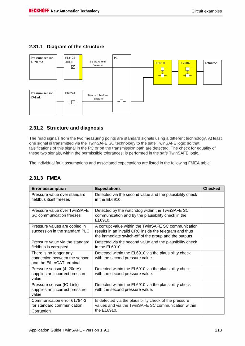
Circuit examples
Application Guide TwinSAFE - version 1.9.1 213
2.31.1 Diagram of the structure
Pressure sensor4..20 mA
EL3124-0090
PCBlackChannel
PressureActuatorEL2904EL6910
Pressure sensorIO-Link
Standard FeldbusPressure
EL6224
2.31.2 Structure and diagnosis
The read signals from the two measuring points are standard signals using a different technology. At least
one signal is transmitted via the TwinSAFE SC technology to the safe TwinSAFE logic so that
falsifications of this signal in the PC or on the transmission path are detected. The check for equality of
these two signals, within the permissible tolerances, is performed in the safe TwinSAFE logic.
The individual fault assumptions and associated expectations are listed in the following FMEA table
2.31.3 FMEA
Error assumption Expectations Checked
Pressure value over standard
fieldbus itself freezes
Detected via the second value and the plausibility check
in the EL6910.
Pressure value over TwinSAFE
SC communication freezes
Detected by the watchdog within the TwinSAFE SC
communication and by the plausibility check in the
EL6910.
Pressure values are copied in
succession in the standard PLC
A corrupt value within the TwinSAFE SC communication
results in an invalid CRC inside the telegram and thus
the immediate switch-off of the group and the outputs
Pressure value via the standard
fieldbus is corrupted
Detected via the second value and the plausibility check
in the EL6910.
There is no longer any
connection between the sensor
and the EtherCAT terminal
Detected within the EL6910 via the plausibility check
with the second pressure value.
Pressure sensor (4..20mA)
supplies an incorrect pressure
value
Detected within the EL6910 via the plausibility check
with the second pressure value.
Pressure sensor (IO-Link)
supplies an incorrect pressure
value
Detected within the EL6910 via the plausibility check
with the second pressure value.
Communication error 61784-3
for standard communication:
Corruption
Is detected via the plausibility check of the pressure
values and via the TwinSAFE SC communication within
the EL6910.

Circuit examples
214 Application Guide TwinSAFE - version 1.9.1
Error assumption Expectations Checked
Communication error 61784-3
for standard communication:
Unintentional repetition
Is detected via the plausibility check of the pressure
values and via the TwinSAFE SC communication within
the EL6910.
Communication error 61784-3
for standard communication:
Wrong sequence
Is detected via the plausibility check of the pressure
values and via the TwinSAFE SC communication within
the EL6910.
Communication error 61784-3
for standard communication:
Loss
Is detected via the plausibility check of the pressure
values and via the TwinSAFE SC communication within
the EL6910.
Communication error 61784-3
for standard communication:
Unacceptable delay
Is detected via the plausibility check of the pressure
values and via the TwinSAFE SC communication within
the EL6910.
Communication error 61784-3
for standard communication:
Insertion
Is detected via the plausibility check of the pressure
values and via the TwinSAFE SC communication within
the EL6910.
Communication error 61784-3
for standard communication:
Masquerading
not relevant for standard, only for safety communication.
Communication error 61784-3
for standard communication:
Addressing
Is detected via the plausibility check of the pressure
values and via the TwinSAFE SC communication within
the EL6910.
Communication error for
standard communication:
Recurrent memory errors in
switches
Is detected via the plausibility check of the pressure
values and via the TwinSAFE SC communication within
the EL6910.
2.31.3.1 Note about TwinSAFE SC communication:
The TwinSAFE SC communication uses the identical mechanisms for error detection as the Safety-over-
EtherCAT communication, the difference being that a different polynomial is used to calculate the
checksum. This polynomial is sufficiently independent of the polynomial used for Safety-over-EtherCAT.
The identical mechanisms are active, such as the black channel principle (bit error probability 10-2).
The quality of the data transmission is not crucial, because ultimately all transmission errors are detected
via the comparison in the safe logic, since this would lead to inequality.

Circuit examples
Application Guide TwinSAFE - version 1.9.1 215
2.31.4 Parameters of the safe output terminal
EL2904
Parameter Value
Current measurement active No
Output test pulses active Yes
2.31.5 Block formation and safety-loops
2.31.5.1 Safety function 1
EL3124-0090
EL6224
EL6910 EL2904
K1
K2Pressure sensor
Pressure sensor
Input1
Input2
2.31.6 Calculation
2.31.6.1 PFH / MTTFD /B10D – values
Component Value
EL2904 – PFH 1,25E-09
EL6910 – PFH 1,79E-09
Pressure sensor 1 (4..20 mA) – MTTF 124 a (1.086.240 h)
Pressure sensor 2 IO-Link – MTTF 201 a (1.760.760 h)
EL3124-0090 - MTBF 950.000 h
EL6224 - MTBF 1.607.919 h
K1 – B10D 1.300.000 h
K2 – B10D 1.300.000 h
Days of operation (dop) 230
Hours of operation / day (hop) 16
Cycle time (minutes) (TZyklus) 10080 (1x per week)
Lifetime (T1) 20 years = 175200 hours
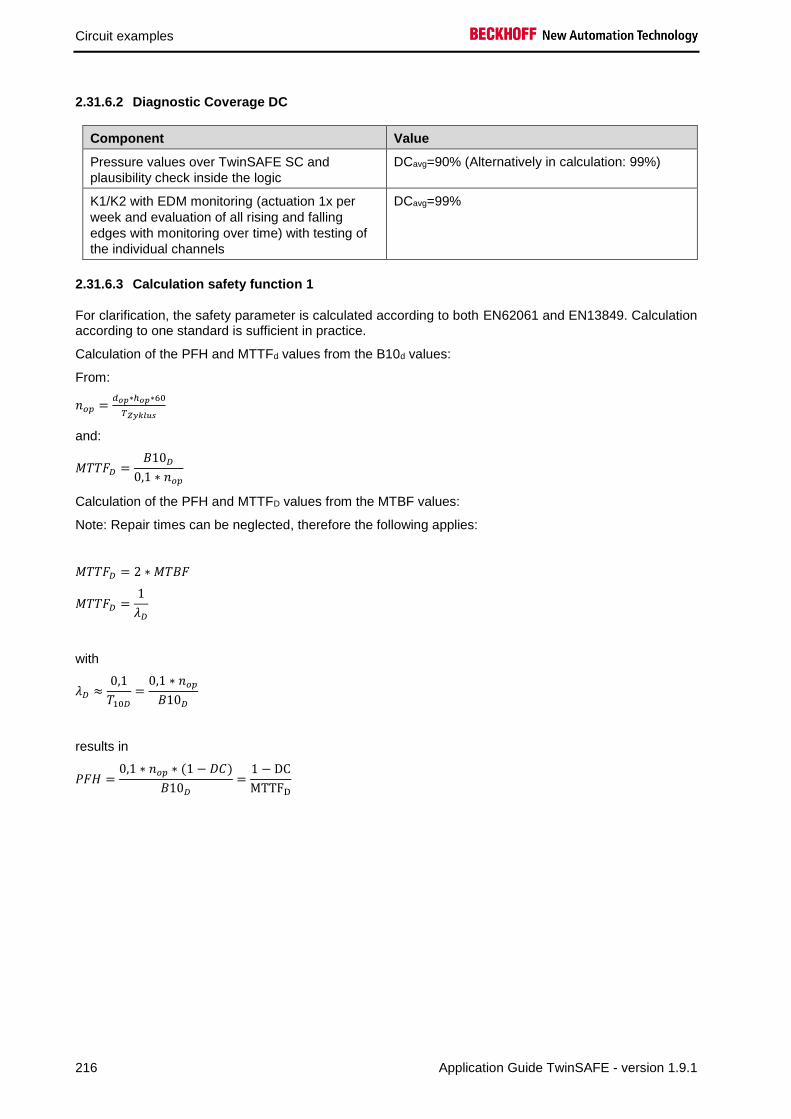
Circuit examples
216 Application Guide TwinSAFE - version 1.9.1
2.31.6.2 Diagnostic Coverage DC
Component Value
Pressure values over TwinSAFE SC and
plausibility check inside the logic
DCavg=90% (Alternatively in calculation: 99%)
K1/K2 with EDM monitoring (actuation 1x per
week and evaluation of all rising and falling
edges with monitoring over time) with testing of
the individual channels
DCavg=99%
2.31.6.3 Calculation safety function 1
For clarification, the safety parameter is calculated according to both EN62061 and EN13849. Calculation according to one standard is sufficient in practice.
Calculation of the PFH and MTTFd values from the B10d values:
From:
𝑛𝑜𝑝 =𝑑𝑜𝑝∗ℎ𝑜𝑝∗60
𝑇𝑍𝑦𝑘𝑙𝑢𝑠
and:
𝑀𝑇𝑇𝐹𝐷 =𝐵10𝐷
0,1 ∗ 𝑛𝑜𝑝
Calculation of the PFH and MTTFD values from the MTBF values:
Note: Repair times can be neglected, therefore the following applies:
𝑀𝑇𝑇𝐹𝐷 = 2 ∗ 𝑀𝑇𝐵𝐹
𝑀𝑇𝑇𝐹𝐷 =1
𝜆𝐷
with
𝜆𝐷 ≈0,1
𝑇10𝐷
=0,1 ∗ 𝑛𝑜𝑝
𝐵10𝐷
results in
𝑃𝐹𝐻 =0,1 ∗ 𝑛𝑜𝑝 ∗ (1 − 𝐷𝐶)
𝐵10𝐷
=1 − DC
MTTFD

Circuit examples
Application Guide TwinSAFE - version 1.9.1 217
Inserting the values, this produces:
Pressure sensor 1 (4-20mA) 𝑀𝑇𝑇𝐹𝐷 = 2 ∗ 𝑀𝑇𝑇𝐹 = 2 ∗ 124 𝑦 = 248 𝑦 = 2.172.480 ℎ
𝑃𝐹𝐻 =1 − DC
MTTFD
=1 − 0,9
2.172.480 ℎ= 4,60E − 08
EL3124-0090 𝑀𝑇𝑇𝐹𝐷 = 2 ∗ 𝑀𝑇𝐵𝐹 = 2 ∗ 950.000 ℎ = 1.900.000 ℎ = 216 𝑦
𝑃𝐹𝐻 =1 − DC
MTTFD
=1 − 0,9
1.900.000 ℎ= 5,26E − 08
Input 1 subsystem
𝑃𝐹𝐻(𝐼𝑛𝑝𝑢𝑡1) = 𝑃𝐹𝐻(𝑃𝑟𝑒𝑠𝑠𝑢𝑟𝑒 𝑠𝑒𝑛𝑠𝑜𝑟1) + 𝑃𝐹𝐻(𝐸𝐿3124−0090) = 4,60𝐸 − 08 + 5,26𝐸 − 08 = 9,86𝐸 − 08
Pressure sensor 2 (IO-Link) 𝑀𝑇𝑇𝐹𝐷 = 2 ∗ 𝑀𝑇𝐵𝐹 = 2 ∗ 1.760.760 ℎ = 3.521.520 ℎ = 402 𝑦
𝑃𝐹𝐻 =1 − DC
MTTFD
=1 − 0,9
3.521.520 ℎ= 2,84E − 08
EL6224 𝑀𝑇𝑇𝐹𝐷 = 2 ∗ 𝑀𝑇𝐵𝐹 = 2 ∗ 1.607.919 ℎ = 3.215.838 ℎ = 367 𝑦
𝑃𝐹𝐻 =1 − DC
MTTFD
=1 − 0,9
3.215.838 ℎ= 3,11E − 08
Input 2 subsystem
𝑃𝐹𝐻(𝐼𝑛𝑝𝑢𝑡2) = 𝑃𝐹𝐻(𝑃𝑟𝑒𝑠𝑠𝑢𝑟𝑒 𝑠𝑒𝑛𝑠𝑜𝑟2) + 𝑃𝐹𝐻(𝐸𝐿6224) = 2,84𝐸 − 08 + 3,11𝐸 − 08 = 5,95𝐸 − 08
K1/K2
𝑛𝑜𝑝 =230∗16∗60
10080= 21,90
𝑀𝑇𝑇𝐹𝐷 =1300000
0,1 ∗ 21,90= 593.607 𝑦 = 5.199.997.320 ℎ
and the assumption that K1 and K2 are each single-channel:
K1/K2: Actuation 1x per week and direct feedback
𝑃𝐹𝐻 =1 − 0,99
593607,3 ∗ 8760= 1,92E − 12

Circuit examples
218 Application Guide TwinSAFE - version 1.9.1
The following assumptions must now be made:
Relays K1 and K2 are both connected to the safety function. The non-functioning of a relay does not lead
to a dangerous situation, but it is discovered by the feedback. Furthermore, the B10d values for K1 and
K2 are identical.
The input signals from pressure sensor 1 with EL3124-0090 and pressure sensor 2 with EL6224 have
different measuring methods, provide both pressure values and are both involved in the safety function. A
non-functioning of a channel does not lead to a dangerous situation, but is detected by the comparison of
the two values in the TwinSAFE logic and leads to a shutdown.
There is a coupling coefficient between the components that are connected via two channels. Examples
are temperature, EMC, voltage peaks or signals between these components. This is assumed to be the
worst-case estimation, where ß =10%. EN 62061 contains tables (Table F.1 criteria for the determination
of the CCF and Table F.2 estimation of the CCF factor (β)) with which this β factor can be determined
exactly. For the input subsystem an estimated value of 2% can be achieved by processing the table to
calculate the β factor. In the following calculation, the worst case is assumed to be 10%.
Further, it is assumed that all usual measures have been taken to prevent both channels failing unsafely
at the same time due to an error (e.g. overcurrent through relay contacts, overtemperature in the control
cabinet)
This produces for the calculation of the PFH value for safety function 1:
𝑃𝐹𝐻𝑔𝑒𝑠 = 𝛽 ∗(𝑃𝐹𝐻(𝐼𝑛𝑝𝑢𝑡1) + 𝑃𝐹𝐻(𝐼𝑛𝑝𝑢𝑡2))
2+ (1 − 𝛽)2 ∗ (𝑃𝐹𝐻(𝐼𝑛𝑝𝑢𝑡1) ∗ 𝑃𝐹𝐻(𝐼𝑛𝑝𝑢𝑡2)) ∗ 𝑇1 + 𝑃𝐹𝐻(𝐸𝐿6910)
+ 𝑃𝐹𝐻(𝐸𝐿2904) + 𝛽 ∗𝑃𝐹𝐻(𝐾1) + 𝑃𝐹𝐻(𝐾2)
2+ (1 − 𝛽)2 ∗ (𝑃𝐹𝐻(𝐾1) ∗ 𝑃𝐹𝐻(𝐾2)) ∗ 𝑇1
Since the portions (1 − 𝛽)2 ∗ (𝑃𝐹𝐻(𝐾1) ∗ 𝑃𝐹𝐻(𝐾2)) ∗ 𝑇1 and (1 − 𝛽)2 ∗ (𝑃𝐹𝐻(𝐼𝑛𝑝𝑢𝑡1) ∗ 𝑃𝐹𝐻(𝐼𝑛𝑝𝑢𝑡2)) ∗ 𝑇1 are
smaller than the rest by the power of ten, they are neglected in this and all further calculations for the
purpose of simplification.
to:
𝑃𝐹𝐻𝑔𝑒𝑠 = 10% ∗9,86𝐸 − 08 + 5,95𝐸 − 08
2+ 1,79𝐸 − 9 + 1,25𝐸 − 9 + 10% ∗
1,92𝐸 − 12 + 1,92𝐸 − 12
2= 7,905𝐸 − 09 + 1,79𝐸 − 09 + 1,25𝐸 − 9 + 1,92𝐸 − 13
𝑷𝑭𝑯𝒈𝒆𝒔 = 𝟏, 𝟎𝟗𝟒𝑬 − 𝟎𝟖
Note
EN 62061
In accordance with EN 62061, the input subsystem is evaluated with an SFF or a DC of 90%. This restricts the achievable SIL value according to table 5 of EN 62061 to a maximum SIL 2.
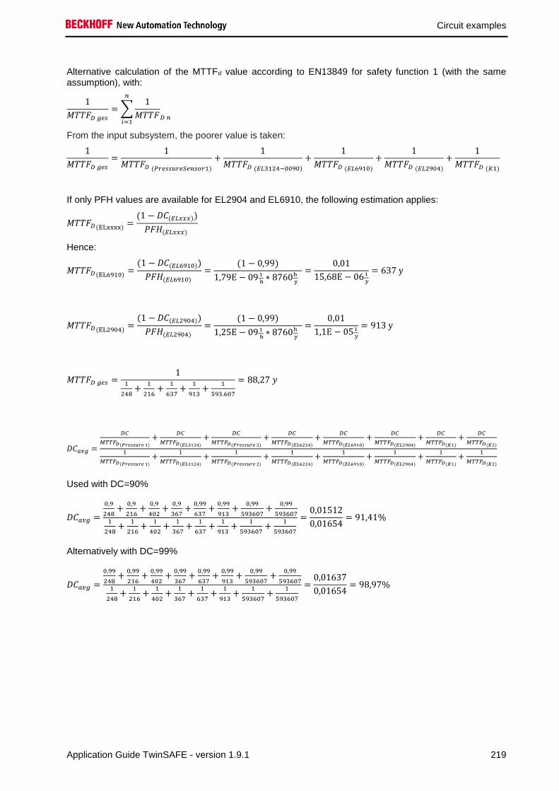
Circuit examples
Application Guide TwinSAFE - version 1.9.1 219
Alternative calculation of the MTTFd value according to EN13849 for safety function 1 (with the same assumption), with:
1
𝑀𝑇𝑇𝐹𝐷 𝑔𝑒𝑠
= ∑1
𝑀𝑇𝑇𝐹𝐷 𝑛
𝑛
𝑖=1
From the input subsystem, the poorer value is taken:
1
𝑀𝑇𝑇𝐹𝐷 𝑔𝑒𝑠
=1
𝑀𝑇𝑇𝐹𝐷 (𝑃𝑟𝑒𝑠𝑠𝑢𝑟𝑒𝑆𝑒𝑛𝑠𝑜𝑟1)
+1
𝑀𝑇𝑇𝐹𝐷 (𝐸𝐿3124−0090)
+1
𝑀𝑇𝑇𝐹𝐷 (𝐸𝐿6910)
+1
𝑀𝑇𝑇𝐹𝐷 (𝐸𝐿2904)
+1
𝑀𝑇𝑇𝐹𝐷 (𝐾1)
If only PFH values are available for EL2904 and EL6910, the following estimation applies:
𝑀𝑇𝑇𝐹𝐷 (ELxxxx)=
(1 − 𝐷𝐶(𝐸𝐿𝑥𝑥𝑥))
𝑃𝐹𝐻(𝐸𝐿𝑥𝑥𝑥)
Hence:
𝑀𝑇𝑇𝐹𝐷 (EL6910)=
(1 − 𝐷𝐶(𝐸𝐿6910))
𝑃𝐹𝐻(𝐸𝐿6910) =
(1 − 0,99)
1,79E − 09 1
h∗ 8760h
y
=0,01
15,68E − 061
y
= 637 y
𝑀𝑇𝑇𝐹𝐷 (EL2904)=
(1 − 𝐷𝐶(𝐸𝐿2904))
𝑃𝐹𝐻(𝐸𝐿2904) =
(1 − 0,99)
1,25E − 09 1
h∗ 8760h
y
=0,01
1,1E − 051
y
= 913 y
𝑀𝑇𝑇𝐹𝐷 𝑔𝑒𝑠 =1
1
248+
1
216+
1
637+
1
913+
1
593.607
= 88,27 𝑦
𝐷𝐶𝑎𝑣𝑔 =
𝐷𝐶
𝑀𝑇𝑇𝐹𝐷(𝑃𝑟𝑒𝑠𝑠𝑢𝑟𝑒 1)
+𝐷𝐶
𝑀𝑇𝑇𝐹𝐷(𝐸𝐿3124)
+𝐷𝐶
𝑀𝑇𝑇𝐹𝐷(𝑃𝑟𝑒𝑠𝑠𝑢𝑟𝑒 2)
+𝐷𝐶
𝑀𝑇𝑇𝐹𝐷(𝐸𝐿6224)
+𝐷𝐶
𝑀𝑇𝑇𝐹𝐷(𝐸𝐿6910)
+𝐷𝐶
𝑀𝑇𝑇𝐹𝐷(𝐸𝐿2904)
+𝐷𝐶
𝑀𝑇𝑇𝐹𝐷(𝐾1)
+𝐷𝐶
𝑀𝑇𝑇𝐹𝐷(𝐾2)
1
𝑀𝑇𝑇𝐹𝐷(𝑃𝑟𝑒𝑠𝑠𝑢𝑟𝑒 1)
+1
𝑀𝑇𝑇𝐹𝐷(𝐸𝐿3124)
+1
𝑀𝑇𝑇𝐹𝐷(𝑃𝑟𝑒𝑠𝑠𝑢𝑟𝑒 2)
+1
𝑀𝑇𝑇𝐹𝐷(𝐸𝐿6224)
+1
𝑀𝑇𝑇𝐹𝐷(𝐸𝐿6910)
+1
𝑀𝑇𝑇𝐹𝐷(𝐸𝐿2904)
+1
𝑀𝑇𝑇𝐹𝐷(𝐾1)
+1
𝑀𝑇𝑇𝐹𝐷(𝐾2)
Used with DC=90%
𝐷𝐶𝑎𝑣𝑔 =
0,9
248+
0,9
216+
0,9
402+
0,9
367+
0,99
637+
0,99
913+
0,99
593607+
0,99
5936071
248+
1
216+
1
402+
1
367+
1
637+
1
913+
1
593607+
1
593607
=0,01512
0,01654= 91,41%
Alternatively with DC=99%
𝐷𝐶𝑎𝑣𝑔 =
0,99
248+
0,99
216+
0,99
402+
0,99
367+
0,99
637+
0,99
913+
0,99
593607+
0,99
5936071
248+
1
216+
1
402+
1
367+
1
637+
1
913+
1
593607+
1
593607
=0,01637
0,01654= 98,97%

Circuit examples
220 Application Guide TwinSAFE - version 1.9.1
CAUTION
Category
This structure is possible up to category 3 at the most.
DC=90% for the input subsystem
MTTFd Designation for each channel Range for each channel
low 3 years ≤ MTTFd < 10 years
medium 10 years ≤ MTTFd < 30 years
high 30 years ≤ MTTFd ≤ 100 years
DCavg Designation Range
none DC < 60 %
low 60 % ≤ DC < 90 %
medium 90 % ≤ DC < 99 %
high 99 % ≤ DC
For practical usability, the number of the ranges was limited to four. An accuracy of 5% is assumed for
the limit values shown in this table.
Category B 1 2 2 3 3 4
DC
MTTFd none none low medium low medium high
low a - a b b c -
medium b - b c c d -
high - c c d d d e

Circuit examples
Application Guide TwinSAFE - version 1.9.1 221
Alternatively with DC=99% for the input subsystem
MTTFd Designation for each channel Range for each channel
low 3 years ≤ MTTFd < 10 years
medium 10 years ≤ MTTFd < 30 years
high 30 years ≤ MTTFd ≤ 100 years
DCavg Designation Range
none DC < 60 %
low 60 % ≤ DC < 90 %
medium 90 % ≤ DC < 99 %
high 99 % ≤ DC
For practical usability, the number of the ranges was limited to four. An accuracy of 5% is assumed for
the limit values shown in this table.
Category B 1 2 2 3 3 4
DC
MTTFd none none low medium low medium high
low a - a b b c -
medium b - b c c d -
high - c c d d d e
Safety integrity level according to Tab. 3 EN62061 Safety integrity level Probability of a dangerous failure per hour
(PFHD)
3 ≥ 10-8 to < 10-7
2 ≥ 10-7 to < 10-6
1 ≥ 10-6 to < 10-5

Circuit examples
222 Application Guide TwinSAFE - version 1.9.1
2.32 Monitoring lifting device (Category 3, PL d)
A lifting device consisting of 2 winches with deflection pulleys for moving a lifting table, should be
monitored in a safe way. The functions of slack rope detection and overload are to be implemented.
There are 2 deflection pulleys with a strain gauge (DMS) sensor on the top of each side of the post, thus
in sum 4 strain gauge sensors. One of these two sensors on one side is read with a TwinSAFE SC
terminal EL3356-0090. The other strain gauge sensor is wired to an EL3751. This provides a strain gauge
mV / V signal, which must be converted into a weight value in the safe logic so that it can be compared
with the value of the EL3356-0090.
2x DMS 2x DMS
1x Encoder 1x Encoder
Winch 2Winch 1
Safety function 1 - Overload
A maximum permissible payload is specified for the lifting device. This must be monitored. For this
purpose, after the plausibility check of the EL3751 and EL3356-0090 signals, a limitation of the result is
made with the limit FB in the EL6910.
According to the risk and hazard analysis of the customer, this safety function is to be assessed with PL c
according to EN 13849-1:2015.
The safety function is built up in a category 3 structure.
Safety function 2 - Slack rope detection
A slack-rope detection is used to detect whether the lifting sled has been mechanically suspended or is
standing on the ground. In either case, a turn off must be done immediately. In addition, it also detects
whether a rope is torn.
According to the risk and hazard analysis of the customer, this safety function is to be assessed with PL c
according to EN 13849-1:2015.
The safety function is built up in a category 3 structure.
Additional function - without safety requirements
By incremental comparison of the encoder values of winch 1 and 2, a synchronous operation can be
checked. This prevents an oblique movement of the lifting sled by the two winches at an early stage.

Circuit examples
Application Guide TwinSAFE - version 1.9.1 223
2.32.1 Diagram of the structure
mechanically linked
lift carriagepulley 1
DMS sensor 1
EL3356-0090
PCBlackChannel
DMS signalActuatorEL2904EL6910
Standard fieldbusDMS signal
DMS sensor 2
EL3751
lift carriagepulley 2
mechanically linked
lift carriagepulley 3
DMS sensor 3
EL3356-0090 BlackChannel
DMS signal
Standard fieldbusDMS signal
DMS sensor 4
EL3751
lift carriagepulley 4
mechanically linked
2.32.2 Structure and diagnosis
The read-in signals of the strain gauge sensors are standard signals that are recorded differently per side.
The first strain gauge sensor is wired to a strain gauge terminal EL3356-0090 which packs the
determined weight value into a safe telegram (FSoE with modified polynomial - TwinSAFE SC) and
transmits it to the EL6910. The second strain gauge sensor is wired to a terminal EL3751, which performs
a strain gauge mV / V measurement. This signal is sent to the EL6910 via the standard communication
path. This signal is converted into a weight value before the plausibility check within the safe logic.
The second side of the lifting device with strain gauge sensor 3 and 4 is identical. For the TwinSAFE SC
communication of the second EL3356-0090 a different polynomial compared to the first side is used. This
is done to detect that the data of both TwinSAFE SC connections is not copied on each other.

Circuit examples
224 Application Guide TwinSAFE - version 1.9.1
2.32.3 FMEA
Error assumption Expectations Checked
Strain gauge signal over
standard fieldbus itself freezes
Detected via the second value and the plausibility check
in the EL6910 (TwinSAFE SC Communication between
EL3356-0090 and EL6910).
Strain gauge signal over
TwinSAFE SC communication
freezes
Detected via the second value and the plausibility check
in the EL6910 and and via the watchdog within the
TwinSAFE SC communication
Strain gauge values are copied
in succession in the standard
PLC
A corrupt value within the TwinSAFE SC communication
results in an invalid CRC inside the telegram and thus
the immediate switch-off of the group and the outputs.
The data types of the two strain gauge values have a
different length because one of the two is packaged in
the TwinSAFE SC telegram (for example, 4 bytes and
11 bytes)
Strain gauge value via the
standard fieldbus is corrupted
Detected via the second value and the plausibility check
in the EL6910 (TwinSAFE SC Communication between
EL3356-0090 and EL6910).
There is no longer a mechanical
connection between the lifting
sled and the winch
Detected within the EL6910 via the plausibility check
with the second strain gauge value.
EL3356-0090 supplies an
incorrect strain gauge value
Detected via the plausibility check with the strain gauge
value of the EL3751 within the EL6910.
EL3751 supplies an incorrect
strain gauge value
Detected via the plausibility check with the strain gauge
value of the EL3356-0090 within the EL6910.
Communication error 61784-3
for standard communication:
Corruption
Is detected via the plausibility check of the strain gauge
values and via the TwinSAFE SC communication within
the EL6910.
Communication error 61784-3
for standard communication:
Unintentional repetition
Is detected via the plausibility check of the strain gauge
values and via the TwinSAFE SC communication within
the EL6910.
Communication error 61784-3
for standard communication:
Wrong sequence
Is detected via the plausibility check of the strain gauge
values and via the TwinSAFE SC communication within
the EL6910.
Communication error 61784-3
for standard communication:
Loss
Is detected via the plausibility check of the strain gauge
values and via the TwinSAFE SC communication within
the EL6910.
Communication error 61784-3
for standard communication:
Unacceptable delay
Is detected via the plausibility check of the strain gauge
values and via the TwinSAFE SC communication within
the EL6910.
Communication error 61784-3
for standard communication:
Insertion
Is detected via the plausibility check of the strain gauge
values and via the TwinSAFE SC communication within
the EL6910.
Communication error 61784-3
for standard communication:
Masquerading
not relevant for standard, only for safety communication.
Communication error 61784-3
for standard communication:
Addressing
Is detected via the plausibility check of the strain gauge
values and via the TwinSAFE SC communication within
the EL6910.

Circuit examples
Application Guide TwinSAFE - version 1.9.1 225
Error assumption Expectations Checked
Communication error for
standard communication:
Recurrent memory errors in
switches
Is detected via the plausibility check of the strain gauge
values and via the TwinSAFE SC communication within
the EL6910.
2.32.3.1 Note about TwinSAFE SC communication:
The TwinSAFE SC communication uses the identical mechanisms for error detection as the Safety-over-
EtherCAT communication, the difference being that a different polynomial is used to calculate the
checksum. This polynomial is sufficiently independent of the polynomial used for Safety-over-EtherCAT.
The identical mechanisms are active, such as the black channel principle (bit error probability 10-2).
The quality of the data transmission is not crucial, because ultimately all transmission errors are detected
via the comparison in the safe logic, since this would lead to inequality.
2.32.4 Structure within the logic
The logic in the EL6910 is divided into 3 parts. In the first section the strain gauge values are scaled and
plausibilised. The restart interlock and the shutdown of the contactors K1 and K2 are also included with
an ESTOP function block.
In the second section, the total load is determined and monitored via a limit function block to a maximum
and minimum. The result is passed to the ESTOP block of the first section.
In the third section, each individual signal is monitored for a minimum value. These 4 signals are linked to
the ESTOP block of the first section.

Circuit examples
226 Application Guide TwinSAFE - version 1.9.1
Section 1
Section 2

Circuit examples
Application Guide TwinSAFE - version 1.9.1 227
Section 3
2.32.5 Parameters of the safe output terminal
EL2904
Parameter Value
Current measurement active No
Output test pulses active Yes

Circuit examples
228 Application Guide TwinSAFE - version 1.9.1
2.32.6 Block formation and safety-loops
2.32.6.1 Safety function 1/2
EL3356-0090
EL3751
EL6910 EL2904
K1
K2DMS sensor 2
DMS sensor 1
Input1
Input2
EL3356-0090
EL3751DMS sensor 4
DMS sensor 3
Input3
Input4
2.32.7 Calculation
2.32.7.1 PFH / MTTFD /B10D – values
Component Value
EL2904 – PFH 1,25E-09
EL6910 – PFH 1,79E-09
Strain gauge Sensor 1-4 – MTTFD
(AST 3570951.1 KAL/10t/D50d11/L205/1,5mV/V)
160 y (1.401.600 h)
EL3356-0090 - MTBF 780.733 h
EL3751 - MTBF 513.333 h
K1 – B10D 1.300.000 h
K2 – B10D 1.300.000 h
Encoder MTBF 107,5 y (914.700 h)
Days of operation (dop) 230
Hours of operation / day (hop) 16
Cycle time (minutes) (Tzyklus) 10080 (1x per week)
Lifetime (T1) 20 years = 175200 hours

Circuit examples
Application Guide TwinSAFE - version 1.9.1 229
2.32.7.2 Diagnostic Coverage DC
Component Value
Strain gauge values over TwinSAFE SC and
plausibility check inside the logic
DCavg=90% (Alternatively in calculation: 99%)
K1/K2 with EDM monitoring (actuation 1x per
week and evaluation of all rising and falling
edges with monitoring over time) with testing of
the individual channels
DCavg=99%
2.32.7.3 Calculation safety function 1/2
For clarification, the safety parameter is calculated according to both EN62061 and EN13849. Calculation according to one standard is sufficient in practice.
Calculation of the PFH and MTTFD values from the B10D values:
From:
𝑛𝑜𝑝 =𝑑𝑜𝑝 ∗ ℎ𝑜𝑝 ∗ 60
𝑇𝑍𝑦𝑘𝑙𝑢𝑠
und:
𝑀𝑇𝑇𝐹𝐷 =𝐵10𝐷
0,1 ∗ 𝑛𝑜𝑝
Calculation of the PFH and MTTFD values from the MTBF values:
Note: Repair times can be neglected, therefore the following applies:
𝑀𝑇𝑇𝐹𝐷 = 2 ∗ 𝑀𝑇𝐵𝐹
𝑀𝑇𝑇𝐹𝐷 =1
𝜆𝐷
with
𝜆𝐷 ≈0,1
𝑇10𝐷
=0,1 ∗ 𝑛𝑜𝑝
𝐵10𝐷
results in
𝑃𝐹𝐻 =0,1 ∗ 𝑛𝑜𝑝 ∗ (1 − 𝐷𝐶)
𝐵10𝐷
=1 − DC
MTTFD

Circuit examples
230 Application Guide TwinSAFE - version 1.9.1
Inserting the values, this produces:
Strain gauge sensor 1 𝑀𝑇𝑇𝐹𝐷 = 1.401.600 ℎ = 160 𝑦
𝑃𝐹𝐻 =1 − DC
MTTFD
=1 − 0,9
1.401.600 ℎ= 7,13E − 08
EL3356-0090 𝑀𝑇𝑇𝐹𝐷 = 2 ∗ 𝑀𝑇𝐵𝐹 = 2 ∗ 780.733 ℎ = 1.561.466 ℎ = 178 𝑦
𝑃𝐹𝐻 =1 − DC
MTTFD
=1 − 0,9
1.561.466 ℎ= 6,40E − 08
Input subsystem 1
𝑃𝐹𝐻(𝐼𝑛𝑝𝑢𝑡1) = 𝑃𝐹𝐻(𝐷𝑀𝑆1) + 𝑃𝐹𝐻(𝐸𝐿3356−0090) = 7,13𝐸 − 08 + 6,40𝐸 − 08 = 13,53𝐸 − 08
Strain gauge sensor 2 𝑀𝑇𝑇𝐹𝐷 = 1.401.600 ℎ = 160 𝑦
𝑃𝐹𝐻 =1 − DC
MTTFD
=1 − 0,9
1.401.600 ℎ= 7,13E − 08
EL3751 𝑀𝑇𝑇𝐹𝐷 = 2 ∗ 𝑀𝑇𝐵𝐹 = 2 ∗ 513.333 ℎ = 1.026.666 ℎ = 117 𝑦
𝑃𝐹𝐻 =1 − DC
MTTFD
=1 − 0,9
1.026.666 ℎ= 9,74E − 08
Input subsystem 2
𝑃𝐹𝐻(𝐼𝑛𝑝𝑢𝑡2) = 𝑃𝐹𝐻(𝐷𝑀𝑆2) + 𝑃𝐹𝐻(𝐸𝐿3751) = 7,13𝐸 − 08 + 9,74𝐸 − 08 = 16,87𝐸 − 08
For input subsystem 3, the values as calculated for input subsystem 1 apply. For input system 4, the values as calculated for input subsystem 2 apply.
K1/K2
𝑛𝑜𝑝 =230 ∗ 16 ∗ 60
10080= 21,90
𝑀𝑇𝑇𝐹𝐷 =1300000
0,1 ∗ 21,90= 593.607 𝑦 = 5.199.997.320 ℎ
and the assumption that K1 and K2 are each single-channel:
K1/K2: Actuation 1x per week and direct feedback
𝑃𝐹𝐻 =1 − 0,99
593607,3 ∗ 8760= 1,92E − 12

Circuit examples
Application Guide TwinSAFE - version 1.9.1 231
The following assumptions must now be made:
Relays K1 and K2 are both connected to the safety function. The non-functioning of a relay does not lead
to a dangerous situation, but it is discovered by the feedback. Furthermore, the B10D values for K1 and
K2 are identical..
The input signals from strain gauge sensor 1 with EL3356-0090 and strain gauge sensor 2 with EL3751
have a different internal structure, have different values (weight value and mV / V value) and are both
involved in the safety function. A non-functioning of a channel does not lead to a dangerous situation, but
is detected by the comparison of the two values in the TwinSAFE logic and leads to a shutdown. An
identical design is used for strain gauge sensors 3 and 4. The sum of the 4 sensors provides the weight
value for the overload cut-off. A lowering of the minimum load of a strain gauge sensor leads to slack
rope shutdown.
There is a coupling coefficient between the components that are connected via two channels. Examples
are temperature, EMC, voltage peaks or signals between these components. This is assumed to be the
worst-case estimation, where ß =10%. EN 62061 contains tables (Table F.1 criteria for the determination
of the CCF and Table F.2 estimation of the CCF factor (β)) with which this β factor can be determined
exactly. For the input subsystem an estimated value of 2% can be achieved by processing the table to
calculate the β factor. In the following calculation, the worst case is assumed to be 10%. Further, it is
assumed that all usual measures have been taken to prevent both channels failing unsafely at the same
time due to an error (e.g. overcurrent through relay contacts, overtemperature in the control cabinet).
This produces for the calculation of the PFH value for safety function 1 / 2
𝑃𝐹𝐻𝐷𝑀𝑆 1/2 = 𝛽 ∗(𝑃𝐹𝐻(𝐼𝑛𝑝𝑢𝑡1) + 𝑃𝐹𝐻(𝐼𝑛𝑝𝑢𝑡2))
2+ (1 − 𝛽)2 ∗ (𝑃𝐹𝐻(𝐼𝑛𝑝𝑢𝑡1) ∗ 𝑃𝐹𝐻(𝐼𝑛𝑝𝑢𝑡2)) ∗ 𝑇1
𝑃𝐹𝐻𝐷𝑀𝑆 1/2 = 0,1 ∗(13,53𝐸 − 08 + 16,87𝐸 − 08)
2= 1,52𝐸 − 08
𝑃𝐹𝐻𝐷𝑀𝑆 3/4 = 𝛽 ∗(𝑃𝐹𝐻(𝐼𝑛𝑝𝑢𝑡3) + 𝑃𝐹𝐻(𝐼𝑛𝑝𝑢𝑡4))
2+ (1 − 𝛽)2 ∗ (𝑃𝐹𝐻(𝐼𝑛𝑝𝑢𝑡3) ∗ 𝑃𝐹𝐻(𝐼𝑛𝑝𝑢𝑡4)) ∗ 𝑇1
𝑃𝐹𝐻𝐷𝑀𝑆 3/4 = 0,1 ∗(13,53𝐸 − 08 + 16,87𝐸 − 08)
2= 1,52𝐸 − 08
𝑃𝐹𝐻𝐾1/𝐾2 = 𝛽 ∗(𝑃𝐹𝐻(𝐾1) + 𝑃𝐹𝐻(𝐾2))
2+ (1 − 𝛽)2 ∗ (𝑃𝐹𝐻(𝐾1) ∗ 𝑃𝐹𝐻(𝐾2)) ∗ 𝑇1
𝑃𝐹𝐻𝐾1/𝐾2 = 0,1 ∗(1,92E − 12 + 1,92E − 12)
2= 1,92𝐸 − 13
Since the portions (1 − 𝛽)2 ∗ (𝑃𝐹𝐻(𝑥) ∗ 𝑃𝐹𝐻(𝑦)) ∗ 𝑇1 are smaller than the rest by the power of ten, they
are neglected in this and all further calculations for the purpose of simplification.
𝑃𝐹𝐻𝑔𝑒𝑠 = 𝑃𝐹𝐻(𝐷𝑀𝑆 1/2) + 𝑃𝐹𝐻(𝐷𝑀𝑆 3/4) + 𝑃𝐹𝐻(𝐸𝐿6910) + 𝑃𝐹𝐻(𝐸𝐿2904) + 𝑃𝐹𝐻(𝐾1/𝐾2)
𝑃𝐹𝐻𝑔𝑒𝑠 = 1,52𝐸 − 08 + 1,52𝐸 − 08 + 1,79𝐸 − 9 + 1,25𝐸 − 9 + 1,92𝐸 − 13
𝑷𝑭𝑯𝒈𝒆𝒔 = 𝟑, 𝟑𝟒𝟒𝑬 − 𝟎𝟖
Note
EN 62061
In accordance with EN 62061, the input subsystem is evaluated with an SFF or a DC of 90%. This restricts the achievable SIL value according to table 5 of EN 62061 to a maximum SIL 2.

Circuit examples
232 Application Guide TwinSAFE - version 1.9.1
Alternative calculation of the MTTFD value according to EN 13849 for safety function 1 / 2 (with the same assumption), with
1
𝑀𝑇𝑇𝐹𝐷 𝑔𝑒𝑠
= ∑1
𝑀𝑇𝑇𝐹𝐷 𝑛
𝑛
𝑖=1
From the input subsystem, the poorer value is taken:
1
𝑀𝑇𝑇𝐹𝐷 𝑔𝑒𝑠
=1
𝑀𝑇𝑇𝐹𝐷 (𝐷𝑀𝑆 𝑆𝑒𝑛𝑠𝑜𝑟 2)
+1
𝑀𝑇𝑇𝐹𝐷 (𝐸𝐿3751)
+1
𝑀𝑇𝑇𝐹𝐷 (𝐸𝐿6910)
+1
𝑀𝑇𝑇𝐹𝐷 (𝐸𝐿2904)
+1
𝑀𝑇𝑇𝐹𝐷 (𝐾1)
If only PFH values are available for EL2904 and EL6910, the following estimation applies:
𝑀𝑇𝑇𝐹𝐷 (ELxxxx)=
(1 − 𝐷𝐶(𝐸𝐿𝑥𝑥𝑥))
𝑃𝐹𝐻(𝐸𝐿𝑥𝑥𝑥)
Hence:
𝑀𝑇𝑇𝐹𝐷 (EL6910)=
(1 − 𝐷𝐶(𝐸𝐿6910))
𝑃𝐹𝐻(𝐸𝐿6910) =
(1 − 0,99)
1,79E − 09 1
h∗ 8760h
y
=0,01
15,68E − 061
y
= 637 y
𝑀𝑇𝑇𝐹𝐷 (EL2904)=
(1 − 𝐷𝐶(𝐸𝐿2904))
𝑃𝐹𝐻(𝐸𝐿2904) =
(1 − 0,99)
1,25E − 09 1
h∗ 8760h
y
=0,01
1,1E − 051
y
= 913 y
𝑀𝑇𝑇𝐹𝐷 𝑔𝑒𝑠 =1
1
160+
1
117+
1
637+
1
913+
1
593.607
= 57,26 𝑦
𝐷𝐶𝑎𝑣𝑔 =
𝐷𝐶
𝑀𝑇𝑇𝐹𝐷(𝐷𝑀𝑆1)
+𝐷𝐶
𝑀𝑇𝑇𝐹𝐷(𝐸𝐿3356)
+𝐷𝐶
𝑀𝑇𝑇𝐹𝐷(𝐷𝑀𝑆2)
+𝐷𝐶
𝑀𝑇𝑇𝐹𝐷(𝐸𝐿3751)
+𝐷𝐶
𝑀𝑇𝑇𝐹𝐷(𝐷𝑀𝑆1)
+𝐷𝐶
𝑀𝑇𝑇𝐹𝐷(𝐸𝐿3356)
+𝐷𝐶
𝑀𝑇𝑇𝐹𝐷(𝐷𝑀𝑆2)
+𝐷𝐶
𝑀𝑇𝑇𝐹𝐷(𝐸𝐿3751)
+𝐷𝐶
𝑀𝑇𝑇𝐹𝐷(𝐸𝐿6910)
+𝐷𝐶
𝑀𝑇𝑇𝐹𝐷(𝐸𝐿2904)
+𝐷𝐶
𝑀𝑇𝑇𝐹𝐷(𝐾1)
+𝐷𝐶
𝑀𝑇𝑇𝐹𝐷(𝐾2)
1
𝑀𝑇𝑇𝐹𝐷(𝐷𝑀𝑆1)
+1
𝑀𝑇𝑇𝐹𝐷(𝐸𝐿3356)
+1
𝑀𝑇𝑇𝐹𝐷(𝐷𝑀𝑆2)
+1
𝑀𝑇𝑇𝐹𝐷(𝐸𝐿3751)
+1
𝑀𝑇𝑇𝐹𝐷(𝐷𝑀𝑆1)
+1
𝑀𝑇𝑇𝐹𝐷(𝐸𝐿3356)
+1
𝑀𝑇𝑇𝐹𝐷(𝐷𝑀𝑆2)
+1
𝑀𝑇𝑇𝐹𝐷(𝐸𝐿3751)
+1
𝑀𝑇𝑇𝐹𝐷(𝐸𝐿6910)
+1
𝑀𝑇𝑇𝐹𝐷(𝐸𝐿2904)
+1
𝑀𝑇𝑇𝐹𝐷(𝐾1)
+1
𝑀𝑇𝑇𝐹𝐷(𝐾2)
Used with DC=90%
𝐷𝐶𝑎𝑣𝑔 =
0,9
160+
0,9
178+
0,9
160+
0,9
117+
0,9
160+
0,9
178+
0,9
160+
0,9
117+
0,99
637+
0,99
913+
0,99
593607+
0,99
5936071
160+
1
178+
1
160+
1
117+
1
160+
1
178+
1
160+
1
117+
1
637+
1
913+
1
593607+
1
593607
=0,0506388
0,0559985= 90,42%
Alternatively with DC=99%
𝐷𝐶𝑎𝑣𝑔 =
0,99
160+
0,99
178+
0,99
160+
0,99
117+
0,99
160+
0,99
178+
0,99
160+
0,99
117+
0,99
637+
0,99
913+
0,99
593607+
0,99
5936071
160+
1
178+
1
160+
1
117+
1
160+
1
178+
1
160+
1
117+
1
637+
1
913+
1
593607+
1
593607
=0,0554385
0,0559985= 98,99%
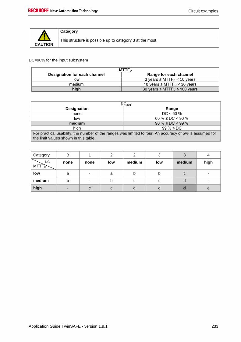
Circuit examples
Application Guide TwinSAFE - version 1.9.1 233
CAUTION
Category
This structure is possible up to category 3 at the most.
DC=90% for the input subsystem
MTTFD Designation for each channel Range for each channel
low 3 years ≤ MTTFD < 10 years
medium 10 years ≤ MTTFD < 30 years
high 30 years ≤ MTTFD ≤ 100 years
DCavg Designation Range
none DC < 60 %
low 60 % ≤ DC < 90 %
medium 90 % ≤ DC < 99 %
high 99 % ≤ DC
For practical usability, the number of the ranges was limited to four. An accuracy of 5% is assumed for
the limit values shown in this table.
Category B 1 2 2 3 3 4
DC
MTTFD none none low medium low medium high
low a - a b b c -
medium b - b c c d -
high - c c d d d e

Circuit examples
234 Application Guide TwinSAFE - version 1.9.1
Alternatively with DC=99% for the input subsystem
MTTFD Designation for each channel Range for each channel
low 3 years ≤ MTTFD < 10 years
medium 10 years ≤ MTTFD < 30 years
high 30 years ≤ MTTFD ≤ 100 years
DCavg Designation Range
none DC < 60 %
low 60 % ≤ DC < 90 %
medium 90 % ≤ DC < 99 %
high 99 % ≤ DC
For practical usability, the number of the ranges was limited to four. An accuracy of 5% is assumed for
the limit values shown in this table.
Category B 1 2 2 3 3 4
DC
MTTFD none none low medium low medium high
low a - a b b c -
medium b - b c c d -
high - c c d d d e
Note
Result
The result with category 3, PL d fulfills or exceeds the requirements of the risk and hazard analysis (PL c).

Planning a safety project with TwinSAFE components
Application Guide TwinSAFE - version 1.9.1 235
3 Planning a safety project with TwinSAFE components
This chapter provides an overview of the general planning process for a safety project using TwinSAFE
components.
CAUTION
Machinery Directive
This description applies only to machines as defined by the Machinery Directive.
CAUTION
Standards
The relevant standards must be available to the user. The following description cannot replace the standard. Typically, the current version of EN ISO 13849-1 and EN ISO 13849-2 or EN 62061 should be available as a minimum. Further useful information can be found in IFA report 2/2017.
3.1 Identifying the risks and hazards
DIN EN ISO 12100 defines an iterative process for risk minimization, for eliminating hazards or for
reducing the risk at machines. It describes the process of risk minimization in a three-step method. In the
first step, the machine should be designed to be inherently safe. If this is not possible, technical protective
measures can be taken to minimize the risk. In the last step, user information about the residual risk can
be provided.
In the first step, the risks and hazards and thus the safety functions must be identified. Machine
manufacturers require precise knowledge of the operation of their machine in order to identify risks and
hazards. Referring to Annex B of EN ISO 12100:2010 is helpful for this purpose.
This risk and hazard analysis should be carried out by persons with knowledge in different areas
(mechanics, electrics, hydraulics, software, maintenance, ...). All operating modes and conditions must be
taken into account, including commissioning, maintenance/servicing, normal operation and
decommissioning. The reasons for or against a particular decision should also be documented. Make
sure that your arguments and justifications are understandable and conclusive.
In this context, it is particularly important to note that safety measures must not yet be taken into account
when assessing the risk.
When all persons involved in the process agree with the result of the analysis, it should be signed by all
involved.
Note
Type C standard
Before you start the following process, you should check whether a type C standard is available for your machine. If this is the case, please follow the steps and instructions given there. If no type C standard is available, you can use the process described below as a guide for the steps to be performed.

Planning a safety project with TwinSAFE components
236 Application Guide TwinSAFE - version 1.9.1
3.2 Determining the PLr / SIL
For each safety function (SF) of the machine identified in the risk and hazard analysis, the machine
manufacturer or user must determine the required Performance Level or SIL Level.
The SIL Level is determined based on the description in Annex A of EN 62061.
The Performance Level is determined based on the risk graph for determining the PLr of EN ISO 13849-1.
Information on the risk graph can be found in Annex A of EN ISO 13849-1:2015.
3.3 Specification of the safety functions
For each safety function identified, it is necessary to specify how the risk should be reduced in
accordance with the EN ISO 12100 strategy for risk reduction.
Risks and hazards whose residual risk is to be reduced by inherently safe design or user information
must be specified, but are not part of this description.
The following explanations refer only to safety functions, the residual risk of which is to be reduced by
technical protective measures.
For these safety functions, the iterative design process for safety-related parts of the control system
(SRP/CS) is carried out in accordance with EN ISO 13849-1:2015.
3.4 Specification of the measures
The machine manufacturer should compile a detailed description of each identified safety function (SF)
whose residual risk is to be reduced by means of technical protection measures. This description contains
information about the hazard, the type of measures taken to reduce the hazard and the required
Performance Level or SIL Level for this safety function.
For each SF, the description of the measures must include the category according to EN ISO 13849-1
and the components to be used, together with their safety parameters (MTTFD, DC, CCF, SFF).
Information on operating states and characteristics is required. These include the operating modes, the
cycle time, the response times or process safety time, the ambient conditions, the frequency of execution,
the operating times, the behavior of the machine in the event of energy loss and more. More detailed
information on this can be found in chapter 5.2 of EN 62061 and chapter 5 of EN ISO 13849-1:2015.
The machine manufacturer must specify and document the description of the safety-related program for
the TwinSAFE Logic, since it forms the basis for the implementation. In addition to selecting the
TwinSAFE components, the function blocks to be used and the sensors and actuators, the
parameterization of the components must also be specified, since this can influence the maximum
achievable Performance Level.
Examples for the implementation of safety functions and the parameterization of the TwinSAFE components can be found in this manual.

Planning a safety project with TwinSAFE components
Application Guide TwinSAFE - version 1.9.1 237
3.5 Implementation of the safety functions
The function blocks are configured in TwinCAT according to the specified safety functions. Predefined
function blocks are available for the typical safety functions, which can be interconnected in a graphical
editor. Safe input and output components provide the interface to sensors and actuators.
Once the entire safety logic and the parameterization of the safe inputs and outputs have been
implemented, a download to the TwinSAFE logic can take place.
A valid user name and password must be provided for the download, together with the serial number of
the device.
The download of the safety program is verified by comparing the CRC of the loaded project (online CRC)
and the calculated CRC from the Safety Editor (offline CRC). The comparison is carried out by TwinCAT
on the one hand and by the user on the other. The user confirms the comparison by ticking the checkbox
and re-entering the password.
The Safety CRC toolbar in TwinCAT can be used at any time to check whether the online CRC matches
the offline CRC, i.e. whether data has been changed in the editor or on the TwinSAFE logic. The following
table is taken from the EL6910 documentation.

Planning a safety project with TwinSAFE components
238 Application Guide TwinSAFE - version 1.9.1
CAUTION
Checking the checksums
The user must verify that the online CRC and the offline CRC match. This is the only way to ensure that a download was carried out after the project was created or modified.
Once all specified safety functions have been implemented in the TwinSAFE logic, the implemented logic
is printed.
In addition to the entire logic, the parameters and the safety addresses of all safety components used, the
printout also contains the calculated project checksum, which is shown on the cover sheet. The
programmer and the customer can document the acceptance of the safety functions with date and
signature on the cover sheet.

Planning a safety project with TwinSAFE components
Application Guide TwinSAFE - version 1.9.1 239
3.6 Proof of achievement of the Performance Level
Once the safety project for the identified safety functions (SF) has been realized, the Performance Level
achieved for these SFs is calculated and verified. Examples for such calculations and verifications can be
found in this manual in chapter Fehler! Verweisquelle konnte nicht gefunden werden..
3.7 Validation of the safety functions
Extract from EN ISO 13849-2:2013, Chapter 4.1: validation guidelines.
ISO 13849-1:2006 is still referenced here. The relevant chapters have the same chapter numbers in the
current version of EN ISO 13849-1:2015.
Further information about the validation can be found in EN ISO 13849-2:2013, for example in Figure 1,
overview of the validation procedure, and in EN ISO 13849-1:2015
The purpose of the validation procedure is to confirm that the design of the safety-related parts of the
control system (SRP/CS) supports the specification of the safety requirements of the machines.
The validation must show that each SRP/CS meets the requirements of ISO 13849-1, particularly
with regard to:
a) the specified safety characteristics of the safety functions, as intended by the design;
b) the requirements for the specified Performance Level (see ISO 13849-1:2006, 4.5):
1. the requirements for the specified category (see ISO 13849-1:2006, 6.2),
2. the measures for controlling and avoiding systematic failures (see ISO 13849-
1:2006, Annex G),
3. the software requirements, if applicable (see ISO 13849-1:2006, 4.6), and
4. the ability to provide a safety function under the expected conditions;
c) the ergonomic design of the user interface, e.g. to discourage the user to act in a dangerous
manner by circumventing the SRP/CS (see ISO 13849-1:2006, 4.8).
The validation should be carried out by persons who not involved in the SRP/CS design.
NOTE: “Independent person” does not necessarily mean that the validation has to be carried out by a
third party.

Planning a safety project with TwinSAFE components
240 Application Guide TwinSAFE - version 1.9.1
3.8 Instructions for checking the SF
All implemented safety functions (SF) have to be checked for correctness. This includes both normal
operation and the function in the event of a fault. Some of the test cases can be read from the defined
safety function with its described measures for risk minimization. For each function, the possible fault
scenarios must be defined and checked accordingly. This information must be recorded in a test
specification or acceptance protocol.
The following list shows some fault scenarios to be considered:
- Discrepancy error of two safe inputs
- Line interruption of the fieldbus used
- Feedback (EDM) error of the actuators
- Failure of the power supply
- Cross-circuit / external feed / line interruption in the wiring
- Violation of a defined limit, e.g. speed limit for axis functions and checking of the defined error
behavior
- ...
The validation must also ensure that all hazards identified by the risk assessment are covered by
appropriate measures and that these measures have actually been implemented.
This applies especially to the life cycle phases of installation/assembly and maintenance. It must be
ensured that any necessary changes or extensions to the safety project are only made after the design
engineer (machine manufacturer) has been notified and the safety specification has been changed by the
manufacturer. A check to see whether an extension of the test specification is necessary must also be
carried out. This applies in particular to machines that are assembled and put into operation at the end
customer's premises.
The test must cover the following points as a minimum:
- I/O Check of the safe inputs and outputs
- Parameterization check of all safety components (watchdog times, sensor tests, FSoE address
etc.)
- Check of the safety functions during normal operation
- Check of the safety functions in the event of an error
- Check of the safe drive functions during normal operation
- Check of the safe drive functions outside the defined safety limits
- Check of the safe drive functions in the event of a power failure
- ...
3.9 Acceptance
The following list contains points which are required for the acceptance of the safety project. This list is not exhaustive. These points must be checked after the initial start-up and after each software modification of the TwinSAFE project.
- Implementation or changes only by qualified personnel - Printout of the TwinSAFE project - Checking of the entire safety project for correctness according to the previous chapter - Comparison of the online CRC of the TwinSAFE project with the offline CRC to ensure that a
download took place after the changes to the safety project. - Implementation and printout of the acceptance protocol - Signature by programmer and customer - This information should be added to the machine documentation - ...

Technical report – TÜV SÜD
Application Guide TwinSAFE - version 1.9.1 241
4 Technical report – TÜV SÜD

Appendix
242 Application Guide TwinSAFE - version 1.9.1
5 Appendix
5.1 Beckhoff Support and Service
Beckhoff and their partners around the world offer comprehensive support and service, making available
fast and competent assistance with all questions related to Beckhoff products and system solutions.
5.1.1 Beckhoff branches and partner companies Beckhoff Support
Please contact your Beckhoff branch office or partner company for local support and service on Beckhoff
products!
The contact addresses for your country can be found in the list of Beckhoff branches and partner
companies: www.beckhoff.com. You will also find further documentation for Beckhoff components there.
5.1.2 Beckhoff company headquarters
Beckhoff Automation GmbH & Co.KG
Huelshorstweg 20
33415 Verl
Germany
Phone: + 49 (0) 5246/963-0
Fax: + 49 (0) 5246/963-198
E-mail: [email protected]
Web: www.beckhoff.com
Beckhoff Support
Support offers you comprehensive technical assistance, helping you not only with the application of
individual Beckhoff products, but also with other, wide-ranging services:
world-wide support
design, programming and commissioning of complex automation systems
and extensive training program for Beckhoff system components
Hotline: + 49 (0) 5246/963-157
Fax: + 49 (0) 5246/963-9157
E-mail: [email protected]
Beckhoff Service
The Beckhoff Service Center supports you in all matters of after-sales service:
on-site service
repair service
spare parts service
hotline service
Hotline: + 49 (0) 5246/963-460
Fax: + 49 (0) 5246/963-479
E-mail: [email protected]