Embed Size (px)
Citation preview
—RELION® 615 SERIES
Transformer Protection and ControlRET615Application Manual

Document ID: 1YHT530003D05Issued: 2019-04-30
Revision: DProduct version: 5.0 FP1
© Copyright 2019 ABB. All rights reserved

Copyright
This document and parts thereof must not be reproduced or copied without writtenpermission from ABB, and the contents thereof must not be imparted to a third party,nor used for any unauthorized purpose.
The software or hardware described in this document is furnished under a license andmay be used, copied, or disclosed only in accordance with the terms of such license.
TrademarksABB and Relion are registered trademarks of the ABB Group. All other brand orproduct names mentioned in this document may be trademarks or registeredtrademarks of their respective holders.
WarrantyPlease inquire about the terms of warranty from your nearest ABB representative.
www.abb.com/relion

Disclaimer
The data, examples and diagrams in this manual are included solely for the concept orproduct description and are not to be deemed as a statement of guaranteed properties.All persons responsible for applying the equipment addressed in this manual mustsatisfy themselves that each intended application is suitable and acceptable, includingthat any applicable safety or other operational requirements are complied with. Inparticular, any risks in applications where a system failure and/or product failurewould create a risk for harm to property or persons (including but not limited topersonal injuries or death) shall be the sole responsibility of the person or entityapplying the equipment, and those so responsible are hereby requested to ensure thatall measures are taken to exclude or mitigate such risks.
This product has been designed to be connected and communicate data andinformation via a network interface which should be connected to a secure network.It is the sole responsibility of the person or entity responsible for networkadministration to ensure a secure connection to the network and to take the necessarymeasures (such as, but not limited to, installation of firewalls, application ofauthentication measures, encryption of data, installation of anti virus programs, etc.)to protect the product and the network, its system and interface included, against anykind of security breaches, unauthorized access, interference, intrusion, leakage and/ortheft of data or information. ABB is not liable for any such damages and/or losses.
This document has been carefully checked by ABB but deviations cannot becompletely ruled out. In case any errors are detected, the reader is kindly requested tonotify the manufacturer. Other than under explicit contractual commitments, in noevent shall ABB be responsible or liable for any loss or damage resulting from the useof this manual or the application of the equipment.

Conformity
This product complies with the directive of the Council of the European Communitieson the approximation of the laws of the Member States relating to electromagneticcompatibility (EMC Directive 2014/30/EU) and concerning electrical equipment foruse within specified voltage limits (Low-voltage directive 2014/35/EU). Thisconformity is the result of tests conducted by the third party testing laboratory Intertekin accordance with the product standard EN 60255-26 for the EMC directive, and withthe product standards EN 60255-1 and EN 60255-27 for the low voltage directive. Theproduct is designed in accordance with the international standards of the IEC 60255series.
Table of contents
Section 1 Introduction.......................................................................5This manual........................................................................................ 5Intended audience.............................................................................. 5Product documentation.......................................................................6
Product documentation set............................................................6Document revision history............................................................. 6Related documentation..................................................................7
Symbols and conventions...................................................................7Symbols.........................................................................................7Document conventions..................................................................8Functions, codes and symbols...................................................... 8Functions, codes and symbols.................................................... 11
Section 2 RET615 overview...........................................................17Overview...........................................................................................17
Product version history................................................................17PCM600 and relay connectivity package version........................18
Operation functionality......................................................................19Optional functions........................................................................19
Physical hardware............................................................................ 19Local HMI......................................................................................... 21
Display.........................................................................................22LEDs............................................................................................23Keypad........................................................................................ 23
Web HMI...........................................................................................24Authorization.....................................................................................25
Audit trail......................................................................................26Communication.................................................................................28
Self-healing Ethernet ring............................................................29Ethernet redundancy................................................................... 30Process bus.................................................................................32Secure communication................................................................34
Section 3 RET615 standard configurations....................................35Standard configurations....................................................................35
Addition of control functions for primary devices and the useof binary inputs and outputs........................................................ 38
Connection diagrams........................................................................39Standard configuration A.................................................................. 43
Applications................................................................................. 43
Table of contents
RET615 1Application Manual
Functions.....................................................................................44Default I/O connections.......................................................... 45Default disturbance recorder settings.....................................47
Functional diagrams.................................................................... 49Functional diagrams for protection......................................... 49Functional diagrams for disturbance recorder........................57Functional diagrams for condition monitoring ........................57Functional diagrams for control and interlocking ...................59Functional diagrams for measurements functions .................62Functional diagrams for I/O and alarm LEDs......................... 64Functional diagrams for other timer logics ............................ 68Other functions....................................................................... 68
Standard configuration B.................................................................. 68Applications................................................................................. 68Functions.....................................................................................69
Default I/O connections.......................................................... 69Default disturbance recorder settings.....................................72
Functional diagrams.................................................................... 74Functional diagrams for protection ........................................ 74Functional diagrams for disturbance recorder .......................81Functional diagrams for condition monitoring ........................82Functional diagrams for control and interlocking ...................84Functional diagrams for measurements functions .................87Functional diagrams for I/O and alarms LEDs ...................... 89Functional diagrams for other timer logics ............................ 93Other functions ...................................................................... 94
Standard configuration E.................................................................. 94Applications................................................................................. 94Functions.....................................................................................95
Default I/O connections.......................................................... 95Default disturbance recorder settings.....................................97
Functional diagrams.................................................................. 100Functional diagrams for protection....................................... 100Functional diagrams for disturbance recorder......................109Functional diagrams for condition monitoring.......................110Functional diagrams for control and interlocking..................112Functional diagrams for measurements functions ...............115Functional diagrams for I/O and alarms LEDs .................... 117Functional diagrams for other timer logics........................... 119Other functions .................................................................... 120
Standard configuration F................................................................ 120Applications............................................................................... 120Functions...................................................................................121
Table of contents
2 RET615Application Manual
Default I/O connections........................................................ 121Default disturbance recorder settings...................................123
Functional diagrams.................................................................. 126Functional diagrams for protection ...................................... 126Functional diagrams for disturbance recorder .....................135Functional diagrams for condition monitoring.......................135Functional diagrams for control and interlocking..................137Functional diagrams for measurements functions ...............140Functional diagrams for I/O and alarms LEDs .................... 142Functional diagrams for other timer logics........................... 144Other functions..................................................................... 145
Standard configuration Z................................................................ 145Applications............................................................................... 145Functions...................................................................................146
Default I/O connections........................................................ 146Default disturbance recorder settings...................................148
Functional diagrams.................................................................. 151Functional diagrams for protection....................................... 151Functional diagrams for disturbance recorder......................154Functional diagrams for condition monitoring.......................155Functional diagrams for control and interlocking..................157Functional diagrams for measurements functions................159Functional diagrams for I/O and alarms LEDs..................... 161Functional diagrams for other timer logics........................... 163Other functions..................................................................... 164
Section 4 Requirements for measurement transformers..............165Current transformers...................................................................... 165
Current transformer requirements for overcurrent protection.... 165Current transformer accuracy class and accuracy limitfactor.................................................................................... 165Non-directional overcurrent protection................................. 166Example for non-directional overcurrent protection..............167
Section 5 Protection relay's physical connections........................169Inputs..............................................................................................169
Energizing inputs.......................................................................169Phase currents..................................................................... 169Residual current................................................................... 169Phase voltages.....................................................................169Residual voltage...................................................................169
Auxiliary supply voltage input.................................................... 170Binary inputs..............................................................................170Optional light sensor inputs....................................................... 172
Table of contents
RET615 3Application Manual

RTD/mA inputs.......................................................................... 172Outputs........................................................................................... 173
Outputs for tripping and controlling............................................173Outputs for signalling.................................................................174IRF.............................................................................................175
Section 6 Glossary....................................................................... 177
Table of contents
4 RET615Application Manual
Section 1 Introduction
1.1 This manual
The application manual contains application descriptions and setting guidelinessorted per function. The manual can be used to find out when and for what purpose atypical protection function can be used. The manual can also be used when calculatingsettings.
1.2 Intended audience
This manual addresses the protection and control engineer responsible for planning,pre-engineering and engineering.
The protection and control engineer must be experienced in electrical powerengineering and have knowledge of related technology, such as protection schemesand principles.
1YHT530003D05 D Section 1Introduction
RET615 5Application Manual
1.3 Product documentation
1.3.1 Product documentation set
Pla
nnin
g &
pu
rcha
se
Eng
inee
ring
Inst
alla
tion
Com
mis
sion
ing
Ope
ratio
n
Mai
nten
ance
Dec
omm
issi
onin
g,
dein
stal
latio
n &
dis
posa
l
Quick start guideQuick installation guideBrochureProduct guideOperation manualInstallation manualConnection diagramEngineering manualTechnical manualApplication manualCommunication protocol manualIEC 61850 engineering guidePoint list manualCyber security deployment guideline
GUID-12DC16B2-2DC1-48DF-8734-0C8B7116124C V2 EN
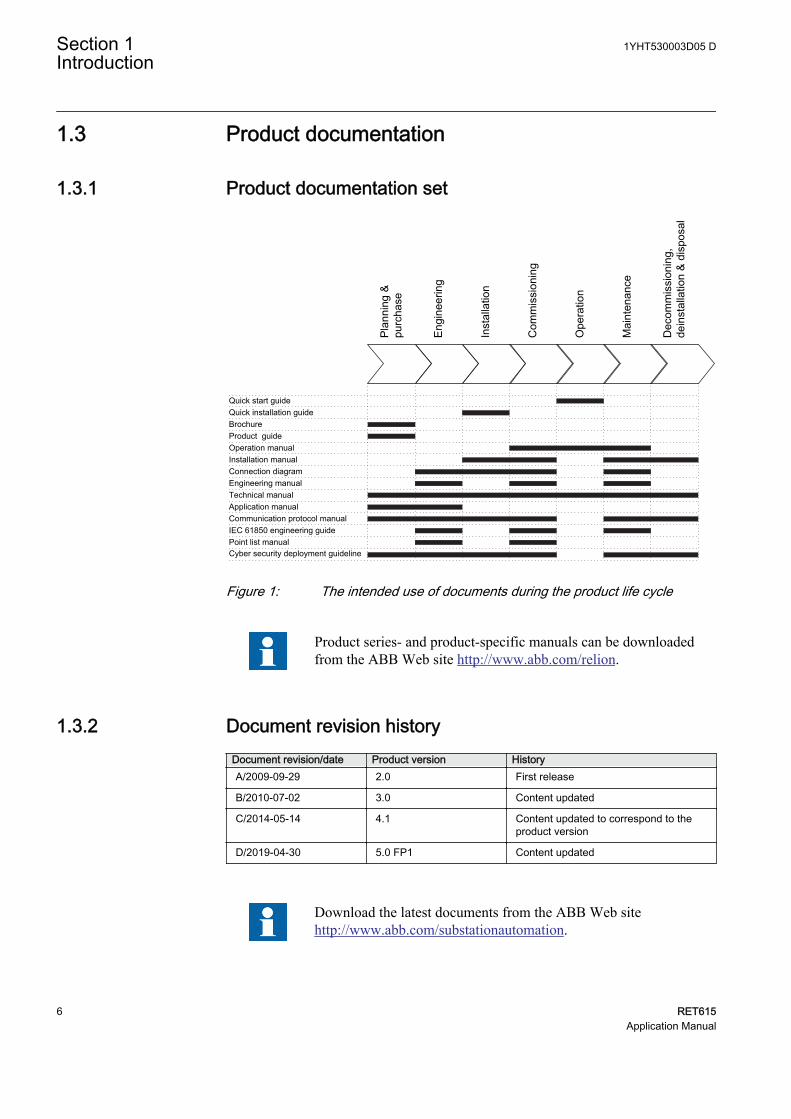
Figure 1: The intended use of documents during the product life cycle
Product series- and product-specific manuals can be downloadedfrom the ABB Web site http://www.abb.com/relion.
1.3.2 Document revision historyDocument revision/date Product version HistoryA/2009-09-29 2.0 First release
B/2010-07-02 3.0 Content updated
C/2014-05-14 4.1 Content updated to correspond to theproduct version
D/2019-04-30 5.0 FP1 Content updated
Download the latest documents from the ABB Web sitehttp://www.abb.com/substationautomation.
Section 1 1YHT530003D05 DIntroduction
6 RET615Application Manual
1.3.3 Related documentationName of the document Document IDModbus Communication Protocol Manual 1MRS759002
IEC 60870-5-103 Communication Protocol Manual 1MRS759001
IEC 61850 Engineering Guide 1MRS759000
Engineering Manual 1MRS758999
Installation Manual 1MRS758997
Operation Manual 1MRS758998
Technical Manual 1YHT530004D05
1.4 Symbols and conventions
1.4.1 Symbols
The electrical warning icon indicates the presence of a hazard whichcould result in electrical shock.
The warning icon indicates the presence of a hazard which couldresult in personal injury.
The caution icon indicates important information or warning relatedto the concept discussed in the text. It might indicate the presence ofa hazard which could result in corruption of software or damage toequipment or property.
The information icon alerts the reader of important facts andconditions.
The tip icon indicates advice on, for example, how to design yourproject or how to use a certain function.
Although warning hazards are related to personal injury, it is necessary to understandthat under certain operational conditions, operation of damaged equipment may resultin degraded process performance leading to personal injury or death. Therefore,comply fully with all warning and caution notices.
1YHT530003D05 D Section 1Introduction
RET615 7Application Manual
1.4.2 Document conventions
A particular convention may not be used in this manual.
• Abbreviations and acronyms are spelled out in the glossary. The glossary alsocontains definitions of important terms.
• Push button navigation in the LHMI menu structure is presented by using thepush button icons.To navigate between the options, use and .
• Menu paths are presented in bold.Select Main menu/Settings.
• LHMI messages are shown in Courier font.To save the changes in nonvolatile memory, select Yes and press .
• Parameter names are shown in italics.The function can be enabled and disabled with the Operation setting.
• Parameter values are indicated with quotation marks.The corresponding parameter values are "On" and "Off".
• Input/output messages and monitored data names are shown in Courier font.When the function starts, the START output is set to TRUE.
• This document assumes that the parameter setting visibility is "Advanced".
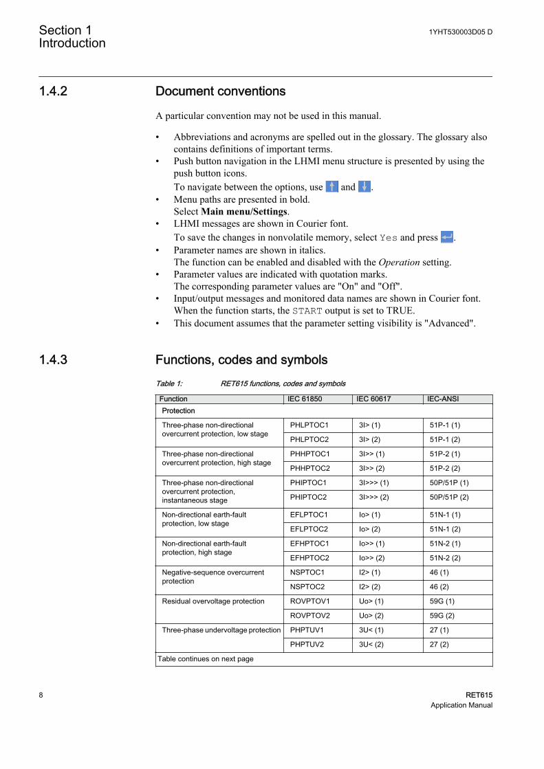
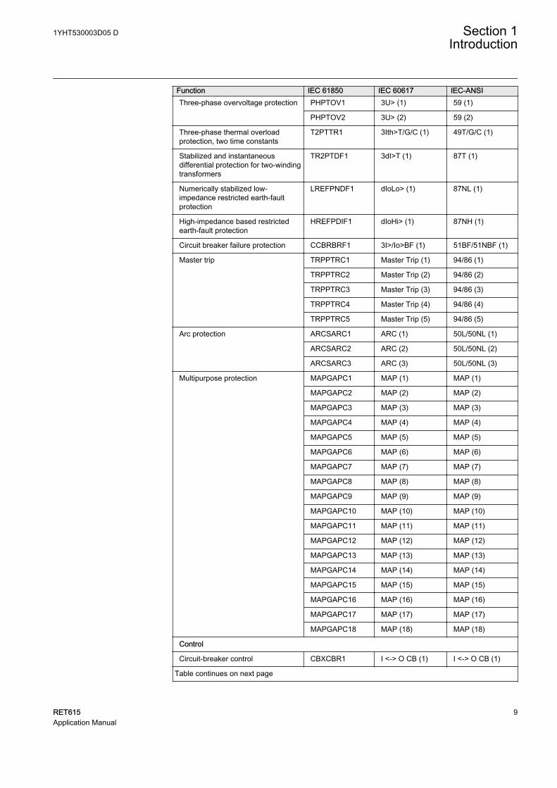
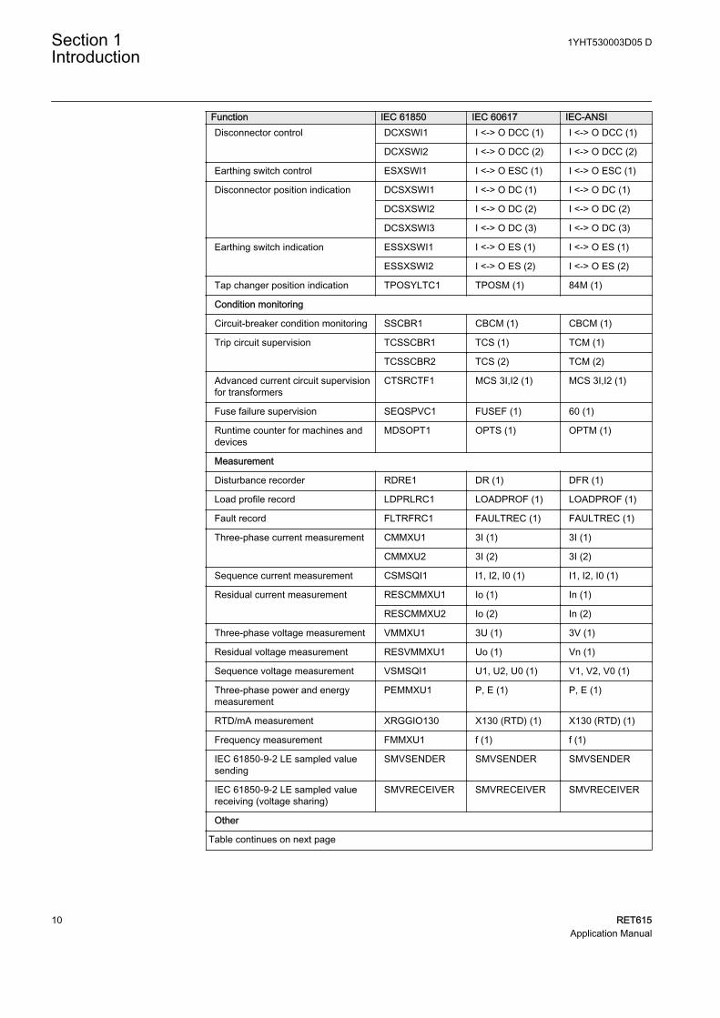
1.4.3 Functions, codes and symbolsTable 1: RET615 functions, codes and symbols
Function IEC 61850 IEC 60617 IEC-ANSIProtection
Three-phase non-directionalovercurrent protection, low stage
PHLPTOC1 3I> (1) 51P-1 (1)
PHLPTOC2 3I> (2) 51P-1 (2)
Three-phase non-directionalovercurrent protection, high stage
PHHPTOC1 3I>> (1) 51P-2 (1)
PHHPTOC2 3I>> (2) 51P-2 (2)
Three-phase non-directionalovercurrent protection,instantaneous stage
PHIPTOC1 3I>>> (1) 50P/51P (1)
PHIPTOC2 3I>>> (2) 50P/51P (2)
Non-directional earth-faultprotection, low stage
EFLPTOC1 Io> (1) 51N-1 (1)
EFLPTOC2 Io> (2) 51N-1 (2)
Non-directional earth-faultprotection, high stage
EFHPTOC1 Io>> (1) 51N-2 (1)
EFHPTOC2 Io>> (2) 51N-2 (2)
Negative-sequence overcurrentprotection
NSPTOC1 I2> (1) 46 (1)
NSPTOC2 I2> (2) 46 (2)
Residual overvoltage protection ROVPTOV1 Uo> (1) 59G (1)
ROVPTOV2 Uo> (2) 59G (2)
Three-phase undervoltage protection PHPTUV1 3U< (1) 27 (1)
PHPTUV2 3U< (2) 27 (2)
Table continues on next page
Section 1 1YHT530003D05 DIntroduction
8 RET615Application Manual
Function IEC 61850 IEC 60617 IEC-ANSIThree-phase overvoltage protection PHPTOV1 3U> (1) 59 (1)
PHPTOV2 3U> (2) 59 (2)
Three-phase thermal overloadprotection, two time constants
T2PTTR1 3Ith>T/G/C (1) 49T/G/C (1)
Stabilized and instantaneousdifferential protection for two-windingtransformers
TR2PTDF1 3dI>T (1) 87T (1)
Numerically stabilized low-impedance restricted earth-faultprotection
LREFPNDF1 dIoLo> (1) 87NL (1)
High-impedance based restrictedearth-fault protection
HREFPDIF1 dIoHi> (1) 87NH (1)
Circuit breaker failure protection CCBRBRF1 3I>/Io>BF (1) 51BF/51NBF (1)
Master trip TRPPTRC1 Master Trip (1) 94/86 (1)
TRPPTRC2 Master Trip (2) 94/86 (2)
TRPPTRC3 Master Trip (3) 94/86 (3)
TRPPTRC4 Master Trip (4) 94/86 (4)
TRPPTRC5 Master Trip (5) 94/86 (5)
Arc protection ARCSARC1 ARC (1) 50L/50NL (1)
ARCSARC2 ARC (2) 50L/50NL (2)
ARCSARC3 ARC (3) 50L/50NL (3)
Multipurpose protection MAPGAPC1 MAP (1) MAP (1)
MAPGAPC2 MAP (2) MAP (2)
MAPGAPC3 MAP (3) MAP (3)
MAPGAPC4 MAP (4) MAP (4)
MAPGAPC5 MAP (5) MAP (5)
MAPGAPC6 MAP (6) MAP (6)
MAPGAPC7 MAP (7) MAP (7)
MAPGAPC8 MAP (8) MAP (8)
MAPGAPC9 MAP (9) MAP (9)
MAPGAPC10 MAP (10) MAP (10)
MAPGAPC11 MAP (11) MAP (11)
MAPGAPC12 MAP (12) MAP (12)
MAPGAPC13 MAP (13) MAP (13)
MAPGAPC14 MAP (14) MAP (14)
MAPGAPC15 MAP (15) MAP (15)
MAPGAPC16 MAP (16) MAP (16)
MAPGAPC17 MAP (17) MAP (17)
MAPGAPC18 MAP (18) MAP (18)
Control
Circuit-breaker control CBXCBR1 I <-> O CB (1) I <-> O CB (1)
Table continues on next page
1YHT530003D05 D Section 1Introduction
RET615 9Application Manual
Function IEC 61850 IEC 60617 IEC-ANSIDisconnector control DCXSWI1 I <-> O DCC (1) I <-> O DCC (1)
DCXSWI2 I <-> O DCC (2) I <-> O DCC (2)
Earthing switch control ESXSWI1 I <-> O ESC (1) I <-> O ESC (1)
Disconnector position indication DCSXSWI1 I <-> O DC (1) I <-> O DC (1)
DCSXSWI2 I <-> O DC (2) I <-> O DC (2)
DCSXSWI3 I <-> O DC (3) I <-> O DC (3)
Earthing switch indication ESSXSWI1 I <-> O ES (1) I <-> O ES (1)
ESSXSWI2 I <-> O ES (2) I <-> O ES (2)
Tap changer position indication TPOSYLTC1 TPOSM (1) 84M (1)
Condition monitoring
Circuit-breaker condition monitoring SSCBR1 CBCM (1) CBCM (1)
Trip circuit supervision TCSSCBR1 TCS (1) TCM (1)
TCSSCBR2 TCS (2) TCM (2)
Advanced current circuit supervisionfor transformers
CTSRCTF1 MCS 3I,I2 (1) MCS 3I,I2 (1)
Fuse failure supervision SEQSPVC1 FUSEF (1) 60 (1)
Runtime counter for machines anddevices
MDSOPT1 OPTS (1) OPTM (1)
Measurement
Disturbance recorder RDRE1 DR (1) DFR (1)
Load profile record LDPRLRC1 LOADPROF (1) LOADPROF (1)
Fault record FLTRFRC1 FAULTREC (1) FAULTREC (1)
Three-phase current measurement CMMXU1 3I (1) 3I (1)
CMMXU2 3I (2) 3I (2)
Sequence current measurement CSMSQI1 I1, I2, I0 (1) I1, I2, I0 (1)
Residual current measurement RESCMMXU1 Io (1) In (1)
RESCMMXU2 Io (2) In (2)
Three-phase voltage measurement VMMXU1 3U (1) 3V (1)
Residual voltage measurement RESVMMXU1 Uo (1) Vn (1)
Sequence voltage measurement VSMSQI1 U1, U2, U0 (1) V1, V2, V0 (1)
Three-phase power and energymeasurement
PEMMXU1 P, E (1) P, E (1)
RTD/mA measurement XRGGIO130 X130 (RTD) (1) X130 (RTD) (1)
Frequency measurement FMMXU1 f (1) f (1)
IEC 61850-9-2 LE sampled valuesending
SMVSENDER SMVSENDER SMVSENDER
IEC 61850-9-2 LE sampled valuereceiving (voltage sharing)
SMVRECEIVER SMVRECEIVER SMVRECEIVER
Other
Table continues on next page
Section 1 1YHT530003D05 DIntroduction
10 RET615Application Manual
Function IEC 61850 IEC 60617 IEC-ANSIMinimum pulse timer (2 pcs) TPGAPC1 TP (1) TP (1)
TPGAPC2 TP (2) TP (2)
TPGAPC3 TP (3) TP (3)
TPGAPC4 TP (4) TP (4)
Minimum pulse timer (2 pcs, secondresolution)
TPSGAPC1 TPS (1) TPS (1)
Minimum pulse timer (2 pcs, minuteresolution)
TPMGAPC1 TPM (1) TPM (1)
Pulse timer (8 pcs) PTGAPC1 PT (1) PT (1)
PTGAPC2 PT (2) PT (2)
Time delay off (8 pcs) TOFGAPC1 TOF (1) TOF (1)
TOFGAPC2 TOF (2) TOF (2)
TOFGAPC3 TOF (3) TOF (3)
TOFGAPC4 TOF (4) TOF (4)
Time delay on (8 pcs) TONGAPC1 TON (1) TON (1)
TONGAPC2 TON (2) TON (2)
TONGAPC3 TON (3) TON (3)
TONGAPC4 TON (4) TON (4)
Set-reset (8 pcs) SRGAPC1 SR (1) SR (1)
SRGAPC2 SR (2) SR (2)
SRGAPC3 SR (3) SR (3)
SRGAPC4 SR (4) SR (4)
Move (8 pcs) MVGAPC1 MV (1) MV (1)
MVGAPC2 MV (2) MV (2)
Generic control point (16 pcs) SPCGAPC1 SPC (1) SPC (1)
SPCGAPC2 SPC (2) SPC (2)
Analog value scaling SCA4GAPC1 SCA4 (1) SCA4 (1)
SCA4GAPC2 SCA4 (2) SCA4 (2)
SCA4GAPC3 SCA4 (3) SCA4 (3)
SCA4GAPC4 SCA4 (4) SCA4 (4)
Integer value move MVI4GAPC1 MVI4 (1) MVI4 (1)
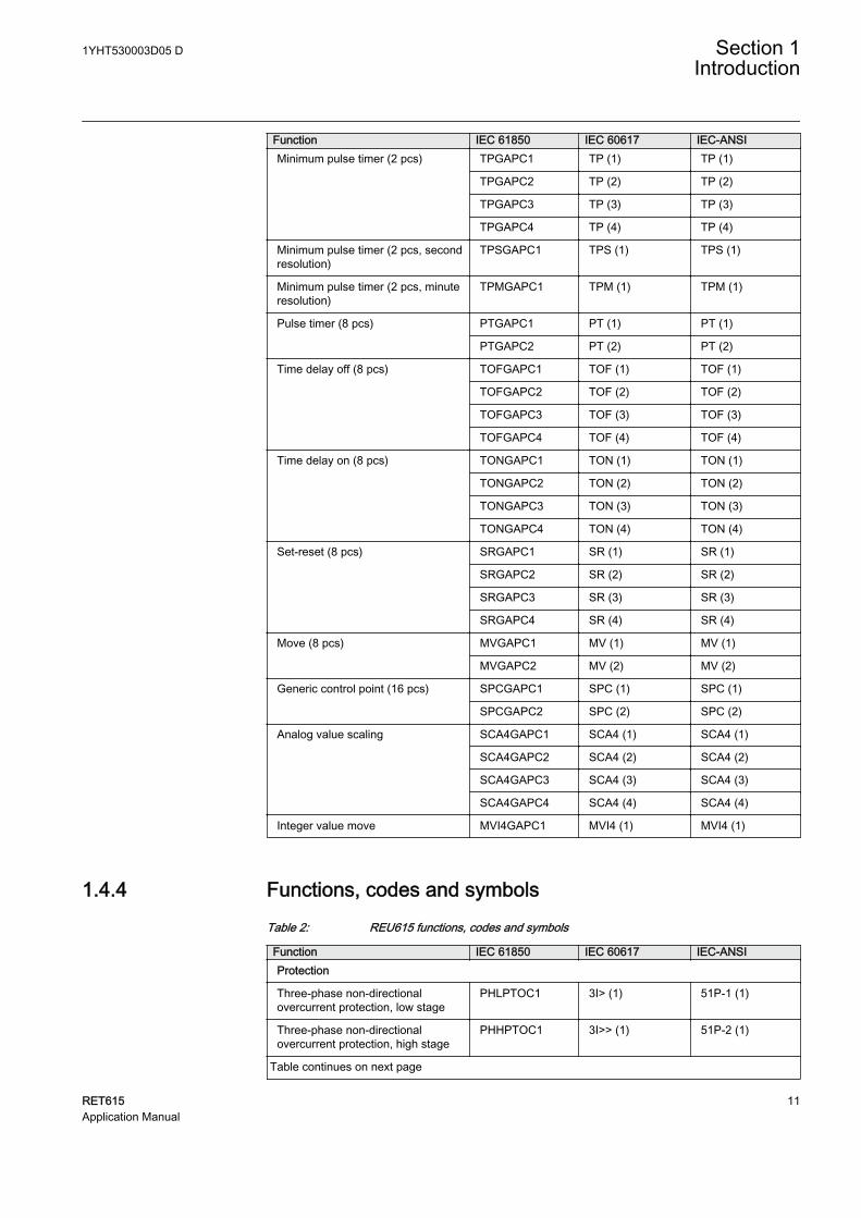
1.4.4 Functions, codes and symbolsTable 2: REU615 functions, codes and symbols
Function IEC 61850 IEC 60617 IEC-ANSIProtection
Three-phase non-directionalovercurrent protection, low stage
PHLPTOC1 3I> (1) 51P-1 (1)
Three-phase non-directionalovercurrent protection, high stage
PHHPTOC1 3I>> (1) 51P-2 (1)
Table continues on next page
1YHT530003D05 D Section 1Introduction
RET615 11Application Manual
Function IEC 61850 IEC 60617 IEC-ANSIThree-phase non-directionalovercurrent protection,instantaneous stage
PHIPTOC1 3I>>> (1) 50P/51P (1)
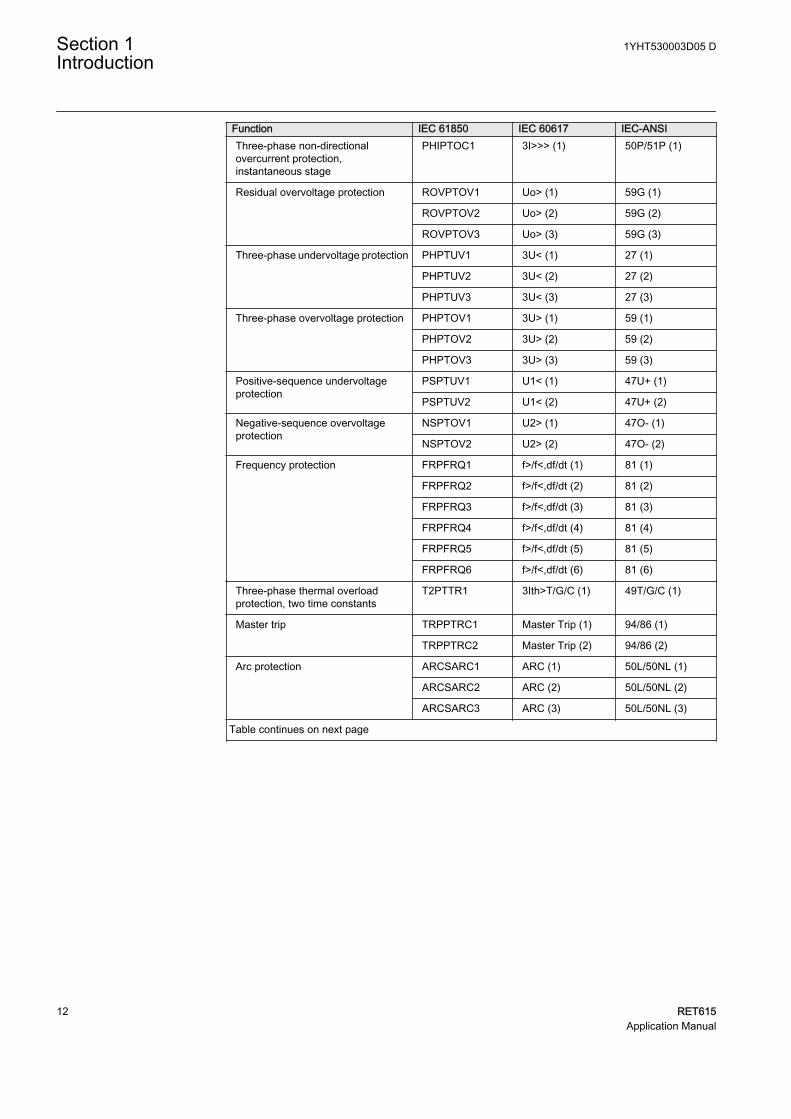
Residual overvoltage protection ROVPTOV1 Uo> (1) 59G (1)
ROVPTOV2 Uo> (2) 59G (2)
ROVPTOV3 Uo> (3) 59G (3)
Three-phase undervoltage protection PHPTUV1 3U< (1) 27 (1)
PHPTUV2 3U< (2) 27 (2)
PHPTUV3 3U< (3) 27 (3)
Three-phase overvoltage protection PHPTOV1 3U> (1) 59 (1)
PHPTOV2 3U> (2) 59 (2)
PHPTOV3 3U> (3) 59 (3)
Positive-sequence undervoltageprotection
PSPTUV1 U1< (1) 47U+ (1)
PSPTUV2 U1< (2) 47U+ (2)
Negative-sequence overvoltageprotection
NSPTOV1 U2> (1) 47O- (1)
NSPTOV2 U2> (2) 47O- (2)
Frequency protection FRPFRQ1 f>/f<,df/dt (1) 81 (1)
FRPFRQ2 f>/f<,df/dt (2) 81 (2)
FRPFRQ3 f>/f<,df/dt (3) 81 (3)
FRPFRQ4 f>/f<,df/dt (4) 81 (4)
FRPFRQ5 f>/f<,df/dt (5) 81 (5)
FRPFRQ6 f>/f<,df/dt (6) 81 (6)
Three-phase thermal overloadprotection, two time constants
T2PTTR1 3Ith>T/G/C (1) 49T/G/C (1)
Master trip TRPPTRC1 Master Trip (1) 94/86 (1)
TRPPTRC2 Master Trip (2) 94/86 (2)
Arc protection ARCSARC1 ARC (1) 50L/50NL (1)
ARCSARC2 ARC (2) 50L/50NL (2)
ARCSARC3 ARC (3) 50L/50NL (3)
Table continues on next page
Section 1 1YHT530003D05 DIntroduction
12 RET615Application Manual
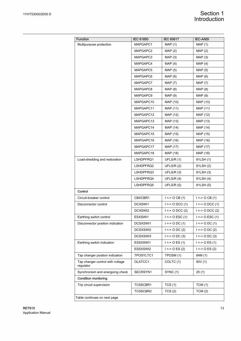
Function IEC 61850 IEC 60617 IEC-ANSIMultipurpose protection MAPGAPC1 MAP (1) MAP (1)
MAPGAPC2 MAP (2) MAP (2)
MAPGAPC3 MAP (3) MAP (3)
MAPGAPC4 MAP (4) MAP (4)
MAPGAPC5 MAP (5) MAP (5)
MAPGAPC6 MAP (6) MAP (6)
MAPGAPC7 MAP (7) MAP (7)
MAPGAPC8 MAP (8) MAP (8)
MAPGAPC9 MAP (9) MAP (9)
MAPGAPC10 MAP (10) MAP (10)
MAPGAPC11 MAP (11) MAP (11)
MAPGAPC12 MAP (12) MAP (12)
MAPGAPC13 MAP (13) MAP (13)
MAPGAPC14 MAP (14) MAP (14)
MAPGAPC15 MAP (15) MAP (15)
MAPGAPC16 MAP (16) MAP (16)
MAPGAPC17 MAP (17) MAP (17)
MAPGAPC18 MAP (18) MAP (18)
Load-shedding and restoration LSHDPFRQ1 UFLS/R (1) 81LSH (1)
LSHDPFRQ2 UFLS/R (2) 81LSH (2)
LSHDPFRQ3 UFLS/R (3) 81LSH (3)
LSHDPFRQ4 UFLS/R (4) 81LSH (4)
LSHDPFRQ5 UFLS/R (5) 81LSH (5)
Control
Circuit-breaker control CBXCBR1 I <-> O CB (1) I <-> O CB (1)
Disconnector control DCXSWI1 I <-> O DCC (1) I <-> O DCC (1)
DCXSWI2 I <-> O DCC (2) I <-> O DCC (2)
Earthing switch control ESXSWI1 I <-> O ESC (1) I <-> O ESC (1)
Disconnector position indication DCSXSWI1 I <-> O DC (1) I <-> O DC (1)
DCSXSWI2 I <-> O DC (2) I <-> O DC (2)
DCSXSWI3 I <-> O DC (3) I <-> O DC (3)
Earthing switch indication ESSXSWI1 I <-> O ES (1) I <-> O ES (1)
ESSXSWI2 I <-> O ES (2) I <-> O ES (2)
Tap changer position indication TPOSYLTC1 TPOSM (1) 84M (1)
Tap changer control with voltageregulator
OLATCC1 COLTC (1) 90V (1)
Synchronism and energizing check SECRSYN1 SYNC (1) 25 (1)
Condition monitoring
Trip circuit supervision TCSSCBR1 TCS (1) TCM (1)
TCSSCBR2 TCS (2) TCM (2)
Table continues on next page
1YHT530003D05 D Section 1Introduction
RET615 13Application Manual
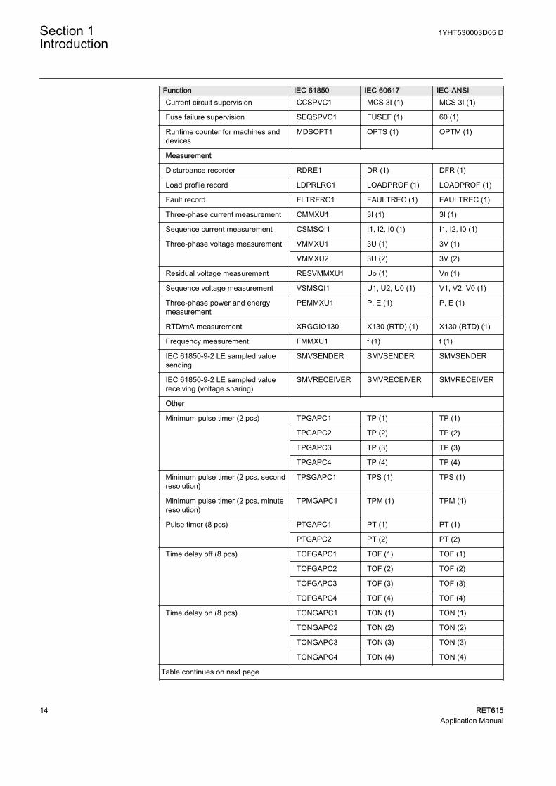
Function IEC 61850 IEC 60617 IEC-ANSICurrent circuit supervision CCSPVC1 MCS 3I (1) MCS 3I (1)
Fuse failure supervision SEQSPVC1 FUSEF (1) 60 (1)
Runtime counter for machines anddevices
MDSOPT1 OPTS (1) OPTM (1)
Measurement
Disturbance recorder RDRE1 DR (1) DFR (1)
Load profile record LDPRLRC1 LOADPROF (1) LOADPROF (1)
Fault record FLTRFRC1 FAULTREC (1) FAULTREC (1)
Three-phase current measurement CMMXU1 3I (1) 3I (1)
Sequence current measurement CSMSQI1 I1, I2, I0 (1) I1, I2, I0 (1)
Three-phase voltage measurement VMMXU1 3U (1) 3V (1)
VMMXU2 3U (2) 3V (2)
Residual voltage measurement RESVMMXU1 Uo (1) Vn (1)
Sequence voltage measurement VSMSQI1 U1, U2, U0 (1) V1, V2, V0 (1)
Three-phase power and energymeasurement
PEMMXU1 P, E (1) P, E (1)
RTD/mA measurement XRGGIO130 X130 (RTD) (1) X130 (RTD) (1)
Frequency measurement FMMXU1 f (1) f (1)
IEC 61850-9-2 LE sampled valuesending
SMVSENDER SMVSENDER SMVSENDER
IEC 61850-9-2 LE sampled valuereceiving (voltage sharing)
SMVRECEIVER SMVRECEIVER SMVRECEIVER
Other
Minimum pulse timer (2 pcs) TPGAPC1 TP (1) TP (1)
TPGAPC2 TP (2) TP (2)
TPGAPC3 TP (3) TP (3)
TPGAPC4 TP (4) TP (4)
Minimum pulse timer (2 pcs, secondresolution)
TPSGAPC1 TPS (1) TPS (1)
Minimum pulse timer (2 pcs, minuteresolution)
TPMGAPC1 TPM (1) TPM (1)
Pulse timer (8 pcs) PTGAPC1 PT (1) PT (1)
PTGAPC2 PT (2) PT (2)
Time delay off (8 pcs) TOFGAPC1 TOF (1) TOF (1)
TOFGAPC2 TOF (2) TOF (2)
TOFGAPC3 TOF (3) TOF (3)
TOFGAPC4 TOF (4) TOF (4)
Time delay on (8 pcs) TONGAPC1 TON (1) TON (1)
TONGAPC2 TON (2) TON (2)
TONGAPC3 TON (3) TON (3)
TONGAPC4 TON (4) TON (4)
Table continues on next page
Section 1 1YHT530003D05 DIntroduction
14 RET615Application Manual

Function IEC 61850 IEC 60617 IEC-ANSISet-reset (8 pcs) SRGAPC1 SR (1) SR (1)
SRGAPC2 SR (2) SR (2)
SRGAPC3 SR (3) SR (3)
SRGAPC4 SR (4) SR (4)
Move (8 pcs) MVGAPC1 MV (1) MV (1)
MVGAPC2 MV (2) MV (2)
Generic control point (16 pcs) SPCGAPC1 SPC (1) SPC (1)
SPCGAPC2 SPC (2) SPC (2)
Analog value scaling SCA4GAPC1 SCA4 (1) SCA4 (1)
SCA4GAPC2 SCA4 (2) SCA4 (2)
SCA4GAPC3 SCA4 (3) SCA4 (3)
SCA4GAPC4 SCA4 (4) SCA4 (4)
Integer value move MVI4GAPC1 MVI4 (1) MVI4 (1)
1YHT530003D05 D Section 1Introduction
RET615 15Application Manual

16
Section 2 RET615 overview
2.1 Overview
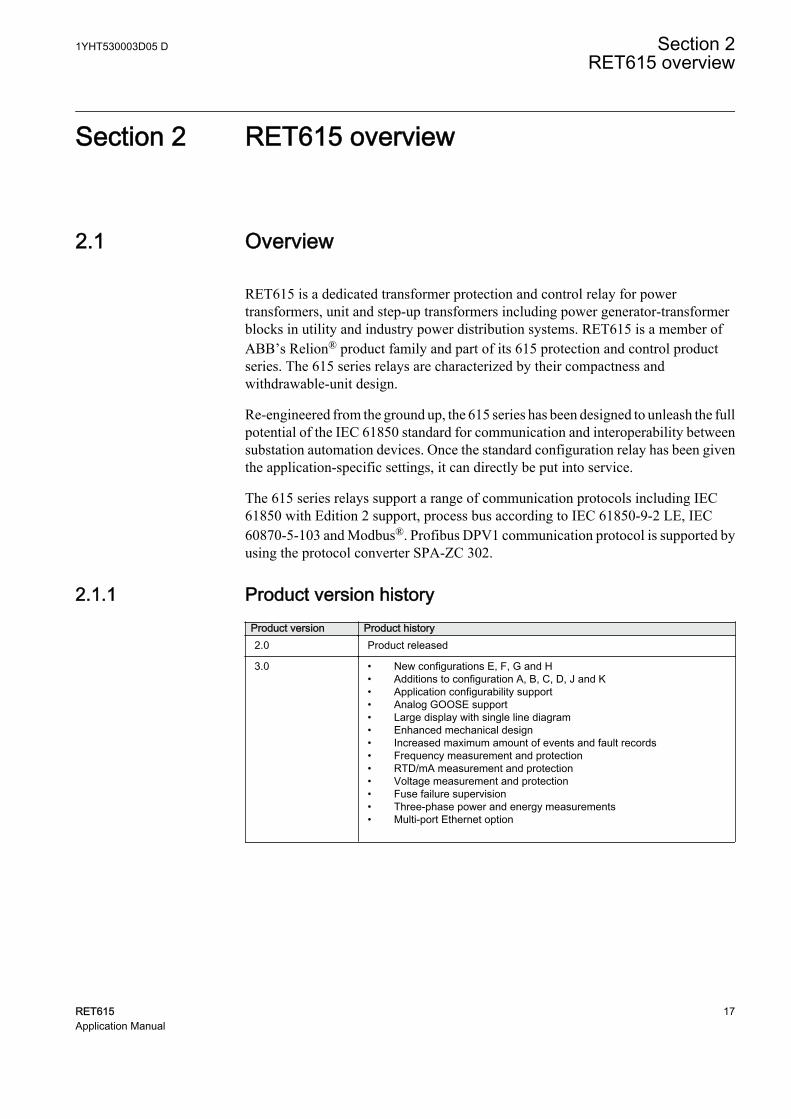
RET615 is a dedicated transformer protection and control relay for powertransformers, unit and step-up transformers including power generator-transformerblocks in utility and industry power distribution systems. RET615 is a member ofABB’s Relion® product family and part of its 615 protection and control productseries. The 615 series relays are characterized by their compactness andwithdrawable-unit design.
Re-engineered from the ground up, the 615 series has been designed to unleash the fullpotential of the IEC 61850 standard for communication and interoperability betweensubstation automation devices. Once the standard configuration relay has been giventhe application-specific settings, it can directly be put into service.
The 615 series relays support a range of communication protocols including IEC61850 with Edition 2 support, process bus according to IEC 61850-9-2 LE, IEC60870-5-103 and Modbus®. Profibus DPV1 communication protocol is supported byusing the protocol converter SPA-ZC 302.
2.1.1 Product version historyProduct version Product history2.0 Product released
3.0 • New configurations E, F, G and H• Additions to configuration A, B, C, D, J and K• Application configurability support• Analog GOOSE support• Large display with single line diagram• Enhanced mechanical design• Increased maximum amount of events and fault records• Frequency measurement and protection• RTD/mA measurement and protection• Voltage measurement and protection• Fuse failure supervision• Three-phase power and energy measurements• Multi-port Ethernet option
1YHT530003D05 D Section 2RET615 overview
RET615 17Application Manual
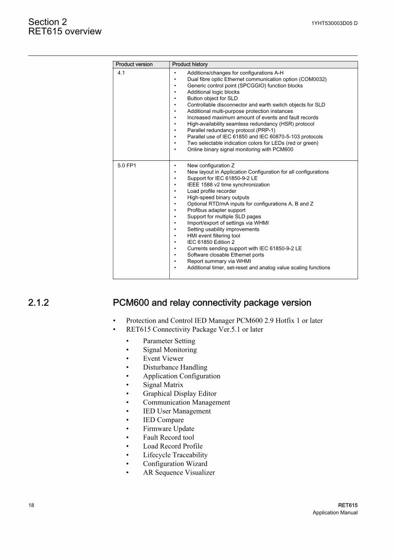
Product version Product history4.1 • Additions/changes for configurations A-H
• Dual fibre optic Ethernet communication option (COM0032)• Generic control point (SPCGGIO) function blocks• Additional logic blocks• Button object for SLD• Controllable disconnector and earth switch objects for SLD• Additional multi-purpose protection instances• Increased maximum amount of events and fault records• High-availability seamless redundancy (HSR) protocol• Parallel redundancy protocol (PRP-1)• Parallel use of IEC 61850 and IEC 60870-5-103 protocols• Two selectable indication colors for LEDs (red or green)• Online binary signal monitoring with PCM600
5.0 FP1 • New configuration Z• New layout in Application Configuration for all configurations• Support for IEC 61850-9-2 LE• IEEE 1588 v2 time synchronization• Load profile recorder• High-speed binary outputs• Optional RTD/mA inputs for configurations A, B and Z• Profibus adapter support• Support for multiple SLD pages• Import/export of settings via WHMI• Setting usability improvements• HMI event filtering tool• IEC 61850 Edition 2• Currents sending support with IEC 61850-9-2 LE• Software closable Ethernet ports• Report summary via WHMI• Additional timer, set-reset and analog value scaling functions
2.1.2 PCM600 and relay connectivity package version
• Protection and Control IED Manager PCM600 2.9 Hotfix 1 or later• RET615 Connectivity Package Ver.5.1 or later
• Parameter Setting• Signal Monitoring• Event Viewer• Disturbance Handling• Application Configuration• Signal Matrix• Graphical Display Editor• Communication Management• IED User Management• IED Compare• Firmware Update• Fault Record tool• Load Record Profile• Lifecycle Traceability• Configuration Wizard• AR Sequence Visualizer
Section 2 1YHT530003D05 DRET615 overview
18 RET615Application Manual

• Label Printing• IEC 61850 Configuration• Differential Characteristics Tool
Download connectivity packages from the ABB Web sitehttp://www.abb.com/substationautomation or directly with UpdateManager in PCM600.
2.2 Operation functionality
2.2.1 Optional functions
• Arc protection• Modbus TCP/IP or RTU/ASCII• IEC 60870-5-103• RTD/mA measurements and multipurpose protection (configurations A, B and Z
only)• IEC 61850-9-2 LE• IEEE 1588 v2 time synchronization
2.3 Physical hardware
The protection relay consists of two main parts: plug-in unit and case. The contentdepends on the ordered functionality.
1YHT530003D05 D Section 2RET615 overview
RET615 19Application Manual
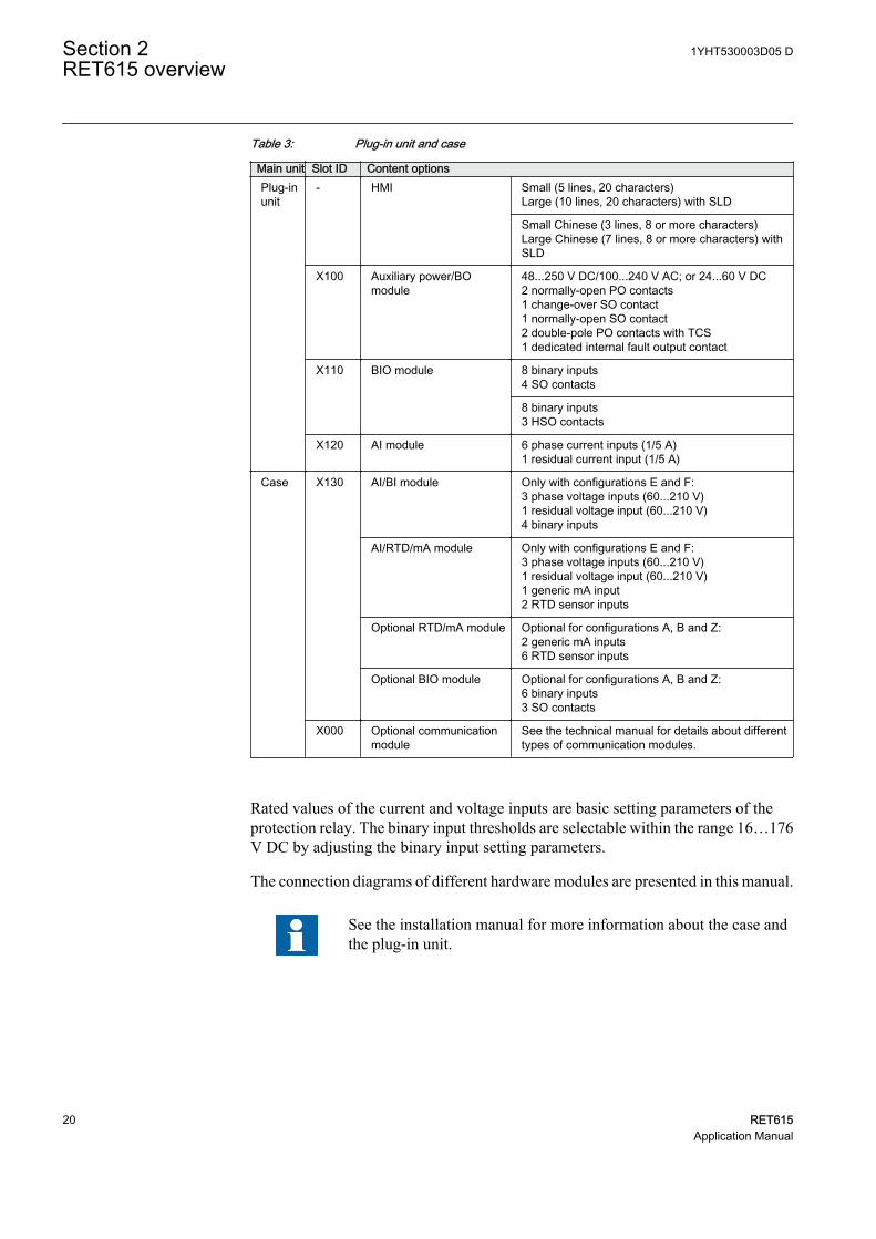
Table 3: Plug-in unit and case
Main unit Slot ID Content optionsPlug-inunit
- HMI Small (5 lines, 20 characters)Large (10 lines, 20 characters) with SLD
Small Chinese (3 lines, 8 or more characters)Large Chinese (7 lines, 8 or more characters) withSLD
X100 Auxiliary power/BOmodule
48...250 V DC/100...240 V AC; or 24...60 V DC2 normally-open PO contacts1 change-over SO contact1 normally-open SO contact2 double-pole PO contacts with TCS1 dedicated internal fault output contact
X110 BIO module 8 binary inputs4 SO contacts
8 binary inputs3 HSO contacts
X120 AI module 6 phase current inputs (1/5 A)1 residual current input (1/5 A)
Case X130 AI/BI module Only with configurations E and F:3 phase voltage inputs (60...210 V)1 residual voltage input (60...210 V)4 binary inputs
AI/RTD/mA module Only with configurations E and F:3 phase voltage inputs (60...210 V)1 residual voltage input (60...210 V)1 generic mA input2 RTD sensor inputs
Optional RTD/mA module Optional for configurations A, B and Z:2 generic mA inputs6 RTD sensor inputs
Optional BIO module Optional for configurations A, B and Z:6 binary inputs3 SO contacts
X000 Optional communicationmodule
See the technical manual for details about differenttypes of communication modules.
Rated values of the current and voltage inputs are basic setting parameters of theprotection relay. The binary input thresholds are selectable within the range 16…176V DC by adjusting the binary input setting parameters.
The connection diagrams of different hardware modules are presented in this manual.
See the installation manual for more information about the case andthe plug-in unit.
Section 2 1YHT530003D05 DRET615 overview
20 RET615Application Manual
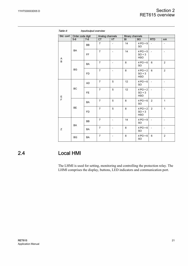
Table 4: Input/output overview
Std. conf. Order code digit Analog channels Binary channels 5-6 7-8 CT VT BI BO RTD mA
AB
BA
BB 7 - 14 4 PO + 9SO
- -
FF7 - 14 4 PO + 5
SO + 3HSO
- -
BG
BA 7 - 8 4 PO + 6SO
6 2
FD7 - 8 4 PO + 2
SO + 3HSO
6 2
EF
BC
AD 7 5 12 4 PO + 6SO
- -
FE7 5 12 4 PO + 2
SO + 3HSO
- -
BE
BA 7 5 8 4 PO + 6SO
2 1
FD7 5 8 4 PO + 2
SO + 3HSO
2 1
ZBA
BB 7 - 14 4 PO + 9SO
- -
BA 7 - 8 4 PO + 6SO
- -
BG BA 7 - 8 4 PO + 6SO
6 2
2.4 Local HMI
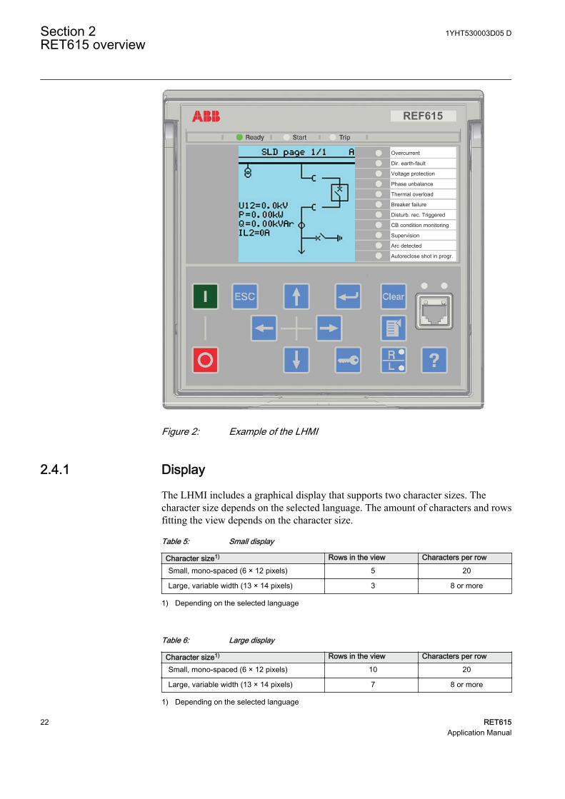
The LHMI is used for setting, monitoring and controlling the protection relay. TheLHMI comprises the display, buttons, LED indicators and communication port.
1YHT530003D05 D Section 2RET615 overview
RET615 21Application Manual
REF615
Overcurrent
Dir. earth-fault
Voltage protection
Phase unbalance
Thermal overload
Breaker failure
Disturb. rec. Triggered
CB condition monitoring
Supervision
Arc detected
Autoreclose shot in progr.
A070704 V4 EN
Figure 2: Example of the LHMI
2.4.1 Display
The LHMI includes a graphical display that supports two character sizes. Thecharacter size depends on the selected language. The amount of characters and rowsfitting the view depends on the character size.
Table 5: Small display
Character size1) Rows in the view Characters per row
Small, mono-spaced (6 × 12 pixels) 5 20
Large, variable width (13 × 14 pixels) 3 8 or more
1) Depending on the selected language
Table 6: Large display
Character size1) Rows in the view Characters per row
Small, mono-spaced (6 × 12 pixels) 10 20
Large, variable width (13 × 14 pixels) 7 8 or more
1) Depending on the selected language
Section 2 1YHT530003D05 DRET615 overview
22 RET615Application Manual
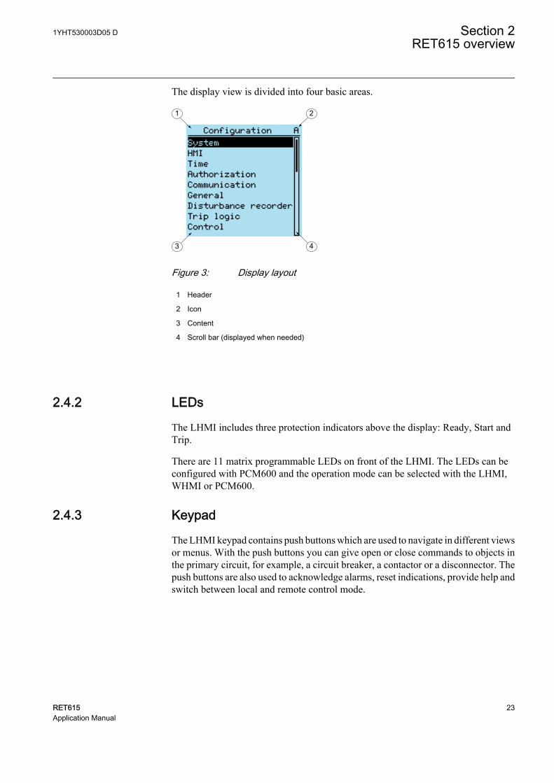
The display view is divided into four basic areas.
1 2
3 4A070705 V3 EN
Figure 3: Display layout
1 Header
2 Icon
3 Content
4 Scroll bar (displayed when needed)
2.4.2 LEDs
The LHMI includes three protection indicators above the display: Ready, Start andTrip.
There are 11 matrix programmable LEDs on front of the LHMI. The LEDs can beconfigured with PCM600 and the operation mode can be selected with the LHMI,WHMI or PCM600.
2.4.3 Keypad
The LHMI keypad contains push buttons which are used to navigate in different viewsor menus. With the push buttons you can give open or close commands to objects inthe primary circuit, for example, a circuit breaker, a contactor or a disconnector. Thepush buttons are also used to acknowledge alarms, reset indications, provide help andswitch between local and remote control mode.
1YHT530003D05 D Section 2RET615 overview
RET615 23Application Manual
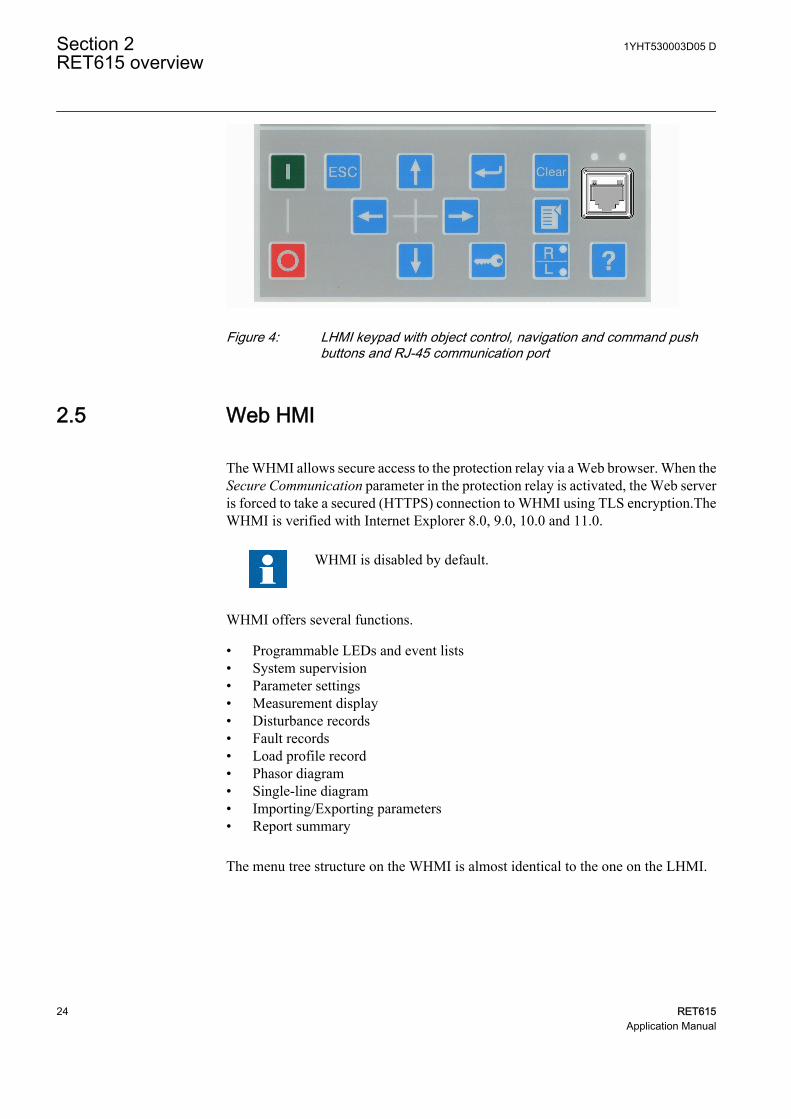
A071176 V1 EN
Figure 4: LHMI keypad with object control, navigation and command pushbuttons and RJ-45 communication port
2.5 Web HMI
The WHMI allows secure access to the protection relay via a Web browser. When theSecure Communication parameter in the protection relay is activated, the Web serveris forced to take a secured (HTTPS) connection to WHMI using TLS encryption.TheWHMI is verified with Internet Explorer 8.0, 9.0, 10.0 and 11.0.
WHMI is disabled by default.
WHMI offers several functions.
• Programmable LEDs and event lists• System supervision• Parameter settings• Measurement display• Disturbance records• Fault records• Load profile record• Phasor diagram• Single-line diagram• Importing/Exporting parameters• Report summary
The menu tree structure on the WHMI is almost identical to the one on the LHMI.
Section 2 1YHT530003D05 DRET615 overview
24 RET615Application Manual
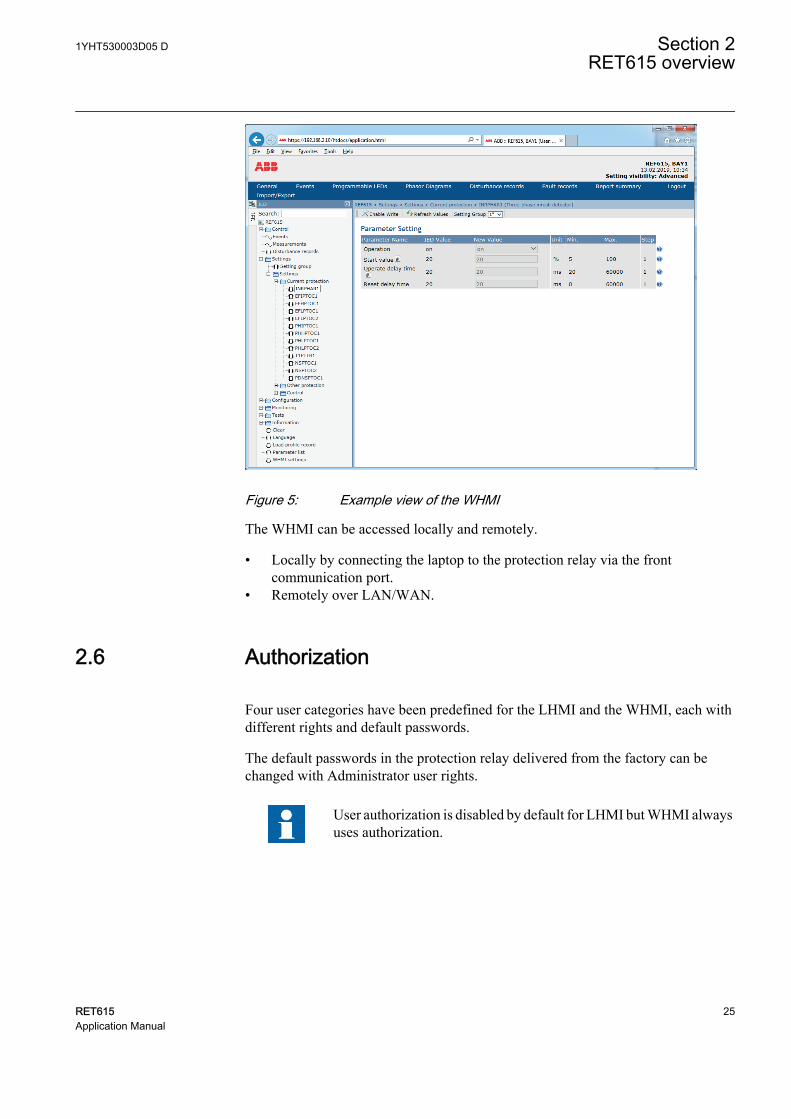
GUID-38AF6905-4903-4C61-B22C-8509D99398E0 V1 EN
Figure 5: Example view of the WHMI
The WHMI can be accessed locally and remotely.
• Locally by connecting the laptop to the protection relay via the frontcommunication port.
• Remotely over LAN/WAN.
2.6 Authorization
Four user categories have been predefined for the LHMI and the WHMI, each withdifferent rights and default passwords.
The default passwords in the protection relay delivered from the factory can bechanged with Administrator user rights.
User authorization is disabled by default for LHMI but WHMI alwaysuses authorization.
1YHT530003D05 D Section 2RET615 overview
RET615 25Application Manual
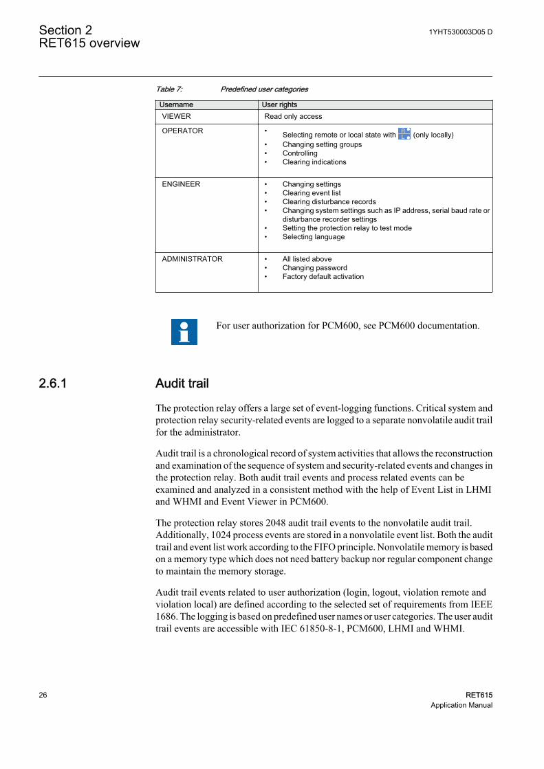
Table 7: Predefined user categories
Username User rightsVIEWER Read only access
OPERATOR • Selecting remote or local state with (only locally)• Changing setting groups• Controlling• Clearing indications
ENGINEER • Changing settings• Clearing event list• Clearing disturbance records• Changing system settings such as IP address, serial baud rate or
disturbance recorder settings• Setting the protection relay to test mode• Selecting language
ADMINISTRATOR • All listed above• Changing password• Factory default activation
For user authorization for PCM600, see PCM600 documentation.
2.6.1 Audit trail
The protection relay offers a large set of event-logging functions. Critical system andprotection relay security-related events are logged to a separate nonvolatile audit trailfor the administrator.
Audit trail is a chronological record of system activities that allows the reconstructionand examination of the sequence of system and security-related events and changes inthe protection relay. Both audit trail events and process related events can beexamined and analyzed in a consistent method with the help of Event List in LHMIand WHMI and Event Viewer in PCM600.
The protection relay stores 2048 audit trail events to the nonvolatile audit trail.Additionally, 1024 process events are stored in a nonvolatile event list. Both the audittrail and event list work according to the FIFO principle. Nonvolatile memory is basedon a memory type which does not need battery backup nor regular component changeto maintain the memory storage.
Audit trail events related to user authorization (login, logout, violation remote andviolation local) are defined according to the selected set of requirements from IEEE1686. The logging is based on predefined user names or user categories. The user audittrail events are accessible with IEC 61850-8-1, PCM600, LHMI and WHMI.
Section 2 1YHT530003D05 DRET615 overview
26 RET615Application Manual
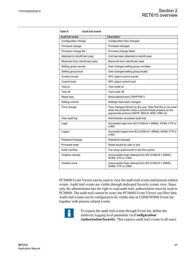
Table 8: Audit trail events
Audit trail event DescriptionConfiguration change Configuration files changed
Firmware change Firmware changed
Firmware change fail Firmware change failed
Attached to retrofit test case Unit has been attached to retrofit case
Removed from retrofit test case Removed from retrofit test case
Setting group remote User changed setting group remotely
Setting group local User changed setting group locally
Control remote DPC object control remote
Control local DPC object control local
Test on Test mode on
Test off Test mode off
Reset trips Reset latched trips (TRPPTRC*)
Setting commit Settings have been changed
Time change Time changed directly by the user. Note that this is not usedwhen the protection relay is synchronised properly by theappropriate protocol (SNTP, IRIG-B, IEEE 1588 v2).
View audit log Administrator accessed audit trail
Login Successful login from IEC 61850-8-1 (MMS), WHMI, FTP orLHMI.
Logout Successful logout from IEC 61850-8-1 (MMS), WHMI, FTP orLHMI.
Password change Password changed
Firmware reset Reset issued by user or tool
Audit overflow Too many audit events in the time period
Violation remote Unsuccessful login attempt from IEC 61850-8-1 (MMS),WHMI, FTP or LHMI.
Violation local Unsuccessful login attempt from IEC 61850-8-1 (MMS),WHMI, FTP or LHMI.
PCM600 Event Viewer can be used to view the audit trail events and process relatedevents. Audit trail events are visible through dedicated Security events view. Sinceonly the administrator has the right to read audit trail, authorization must be used inPCM600. The audit trail cannot be reset, but PCM600 Event Viewer can filter data.Audit trail events can be configured to be visible also in LHMI/WHMI Event listtogether with process related events.
To expose the audit trail events through Event list, define theAuthority logging level parameter via Configuration/Authorization/Security. This exposes audit trail events to all users.
1YHT530003D05 D Section 2RET615 overview
RET615 27Application Manual
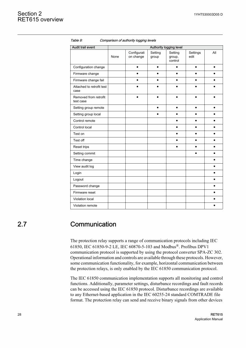
Table 9: Comparison of authority logging levels
Audit trail event Authority logging level
NoneConfiguration change
Settinggroup
Settinggroup,control
Settingsedit
All
Configuration change ● ● ● ● ●
Firmware change ● ● ● ● ●
Firmware change fail ● ● ● ● ●
Attached to retrofit testcase
● ● ● ● ●
Removed from retrofittest case
● ● ● ● ●
Setting group remote ● ● ● ●
Setting group local ● ● ● ●
Control remote ● ● ●
Control local ● ● ●
Test on ● ● ●
Test off ● ● ●
Reset trips ● ● ●
Setting commit ● ●
Time change ●
View audit log ●
Login ●
Logout ●
Password change ●
Firmware reset ●
Violation local ●
Violation remote ●
2.7 Communication
The protection relay supports a range of communication protocols including IEC61850, IEC 61850-9-2 LE, IEC 60870-5-103 and Modbus®. Profibus DPV1communication protocol is supported by using the protocol converter SPA-ZC 302.Operational information and controls are available through these protocols. However,some communication functionality, for example, horizontal communication betweenthe protection relays, is only enabled by the IEC 61850 communication protocol.
The IEC 61850 communication implementation supports all monitoring and controlfunctions. Additionally, parameter settings, disturbance recordings and fault recordscan be accessed using the IEC 61850 protocol. Disturbance recordings are availableto any Ethernet-based application in the IEC 60255-24 standard COMTRADE fileformat. The protection relay can send and receive binary signals from other devices
Section 2 1YHT530003D05 DRET615 overview
28 RET615Application Manual
(so-called horizontal communication) using the IEC 61850-8-1 GOOSE profile,where the highest performance class with a total transmission time of 3 ms issupported. Furthermore, the protection relay supports sending and receiving of analogvalues using GOOSE messaging. The protection relay meets the GOOSEperformance requirements for tripping applications in distribution substations, asdefined by the IEC 61850 standard.
The protection relay can support five simultaneous clients. If PCM600 reserves oneclient connection, only four client connections are left, for example, for IEC 61850and Modbus.
All communication connectors, except for the front port connector, are placed onintegrated optional communication modules. The protection relay can be connected toEthernet-based communication systems via the RJ-45 connector (100Base-TX) or thefiber-optic LC connector (100Base-FX).
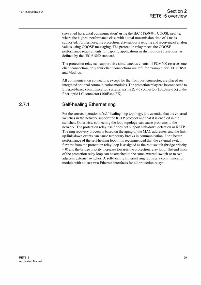
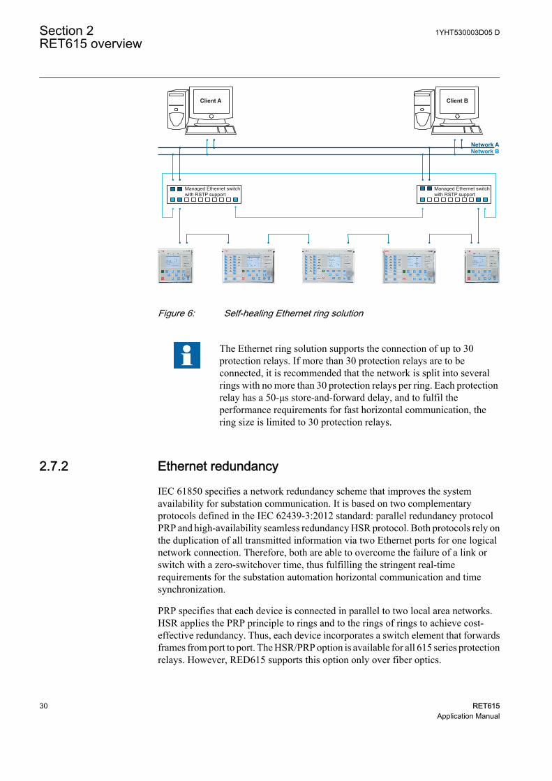
2.7.1 Self-healing Ethernet ring
For the correct operation of self-healing loop topology, it is essential that the externalswitches in the network support the RSTP protocol and that it is enabled in theswitches. Otherwise, connecting the loop topology can cause problems to thenetwork. The protection relay itself does not support link-down detection or RSTP.The ring recovery process is based on the aging of the MAC addresses, and the link-up/link-down events can cause temporary breaks in communication. For a betterperformance of the self-healing loop, it is recommended that the external switchfurthest from the protection relay loop is assigned as the root switch (bridge priority= 0) and the bridge priority increases towards the protection relay loop. The end linksof the protection relay loop can be attached to the same external switch or to twoadjacent external switches. A self-healing Ethernet ring requires a communicationmodule with at least two Ethernet interfaces for all protection relays.
1YHT530003D05 D Section 2RET615 overview
RET615 29Application Manual
Managed Ethernet switchwith RSTP support
Managed Ethernet switchwith RSTP support
Client BClient A
Network ANetwork B
GUID-283597AF-9F38-4FC7-B87A-73BFDA272D0F V3 EN
Figure 6: Self-healing Ethernet ring solution
The Ethernet ring solution supports the connection of up to 30protection relays. If more than 30 protection relays are to beconnected, it is recommended that the network is split into severalrings with no more than 30 protection relays per ring. Each protectionrelay has a 50-μs store-and-forward delay, and to fulfil theperformance requirements for fast horizontal communication, thering size is limited to 30 protection relays.
2.7.2 Ethernet redundancy
IEC 61850 specifies a network redundancy scheme that improves the systemavailability for substation communication. It is based on two complementaryprotocols defined in the IEC 62439-3:2012 standard: parallel redundancy protocolPRP and high-availability seamless redundancy HSR protocol. Both protocols rely onthe duplication of all transmitted information via two Ethernet ports for one logicalnetwork connection. Therefore, both are able to overcome the failure of a link orswitch with a zero-switchover time, thus fulfilling the stringent real-timerequirements for the substation automation horizontal communication and timesynchronization.
PRP specifies that each device is connected in parallel to two local area networks.HSR applies the PRP principle to rings and to the rings of rings to achieve cost-effective redundancy. Thus, each device incorporates a switch element that forwardsframes from port to port. The HSR/PRP option is available for all 615 series protectionrelays. However, RED615 supports this option only over fiber optics.
Section 2 1YHT530003D05 DRET615 overview
30 RET615Application Manual
IEC 62439-3:2012 cancels and replaces the first edition published in2010. These standard versions are also referred to as IEC 62439-3Edition 1 and IEC 62439-3 Edition 2. The protection relay supportsIEC 62439-3:2012 and it is not compatible with IEC 62439-3:2010.
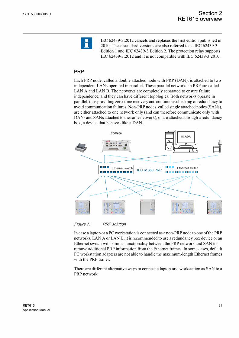
PRPEach PRP node, called a double attached node with PRP (DAN), is attached to twoindependent LANs operated in parallel. These parallel networks in PRP are calledLAN A and LAN B. The networks are completely separated to ensure failureindependence, and they can have different topologies. Both networks operate inparallel, thus providing zero-time recovery and continuous checking of redundancy toavoid communication failures. Non-PRP nodes, called single attached nodes (SANs),are either attached to one network only (and can therefore communicate only withDANs and SANs attached to the same network), or are attached through a redundancybox, a device that behaves like a DAN.
Ethernet switchIEC 61850 PRPEthernet switch
SCADACOM600
GUID-334D26B1-C3BD-47B6-BD9D-2301190A5E9D V2 EN
Figure 7: PRP solution
In case a laptop or a PC workstation is connected as a non-PRP node to one of the PRPnetworks, LAN A or LAN B, it is recommended to use a redundancy box device or anEthernet switch with similar functionality between the PRP network and SAN toremove additional PRP information from the Ethernet frames. In some cases, defaultPC workstation adapters are not able to handle the maximum-length Ethernet frameswith the PRP trailer.
There are different alternative ways to connect a laptop or a workstation as SAN to aPRP network.
1YHT530003D05 D Section 2RET615 overview
RET615 31Application Manual
• Via an external redundancy box (RedBox) or a switch capable of connecting toPRP and normal networks
• By connecting the node directly to LAN A or LAN B as SAN• By connecting the node to the protection relay's interlink port
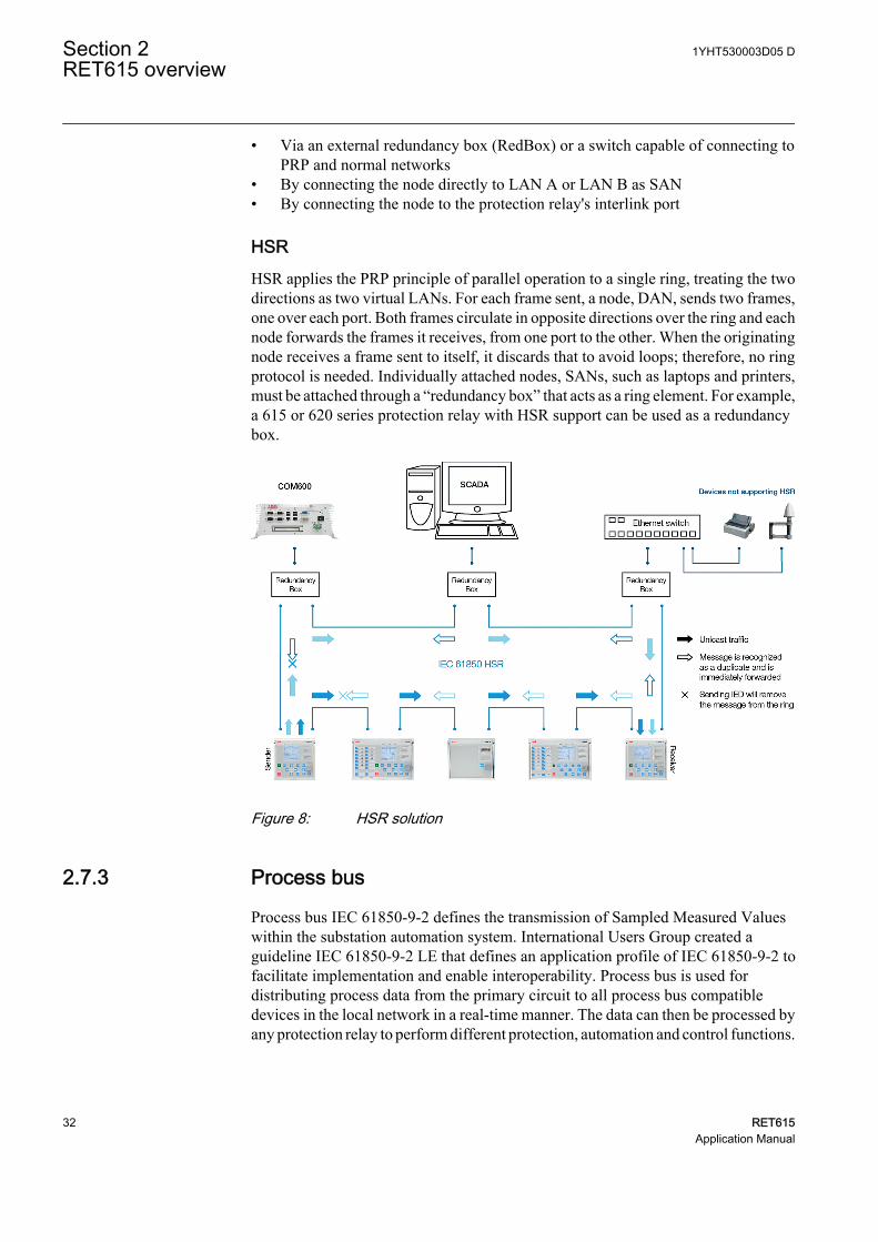
HSRHSR applies the PRP principle of parallel operation to a single ring, treating the twodirections as two virtual LANs. For each frame sent, a node, DAN, sends two frames,one over each port. Both frames circulate in opposite directions over the ring and eachnode forwards the frames it receives, from one port to the other. When the originatingnode receives a frame sent to itself, it discards that to avoid loops; therefore, no ringprotocol is needed. Individually attached nodes, SANs, such as laptops and printers,must be attached through a “redundancy box” that acts as a ring element. For example,a 615 or 620 series protection relay with HSR support can be used as a redundancybox.
GUID-207430A7-3AEC-42B2-BC4D-3083B3225990 V2 EN
Figure 8: HSR solution
2.7.3 Process bus
Process bus IEC 61850-9-2 defines the transmission of Sampled Measured Valueswithin the substation automation system. International Users Group created aguideline IEC 61850-9-2 LE that defines an application profile of IEC 61850-9-2 tofacilitate implementation and enable interoperability. Process bus is used fordistributing process data from the primary circuit to all process bus compatibledevices in the local network in a real-time manner. The data can then be processed byany protection relay to perform different protection, automation and control functions.
Section 2 1YHT530003D05 DRET615 overview
32 RET615Application Manual
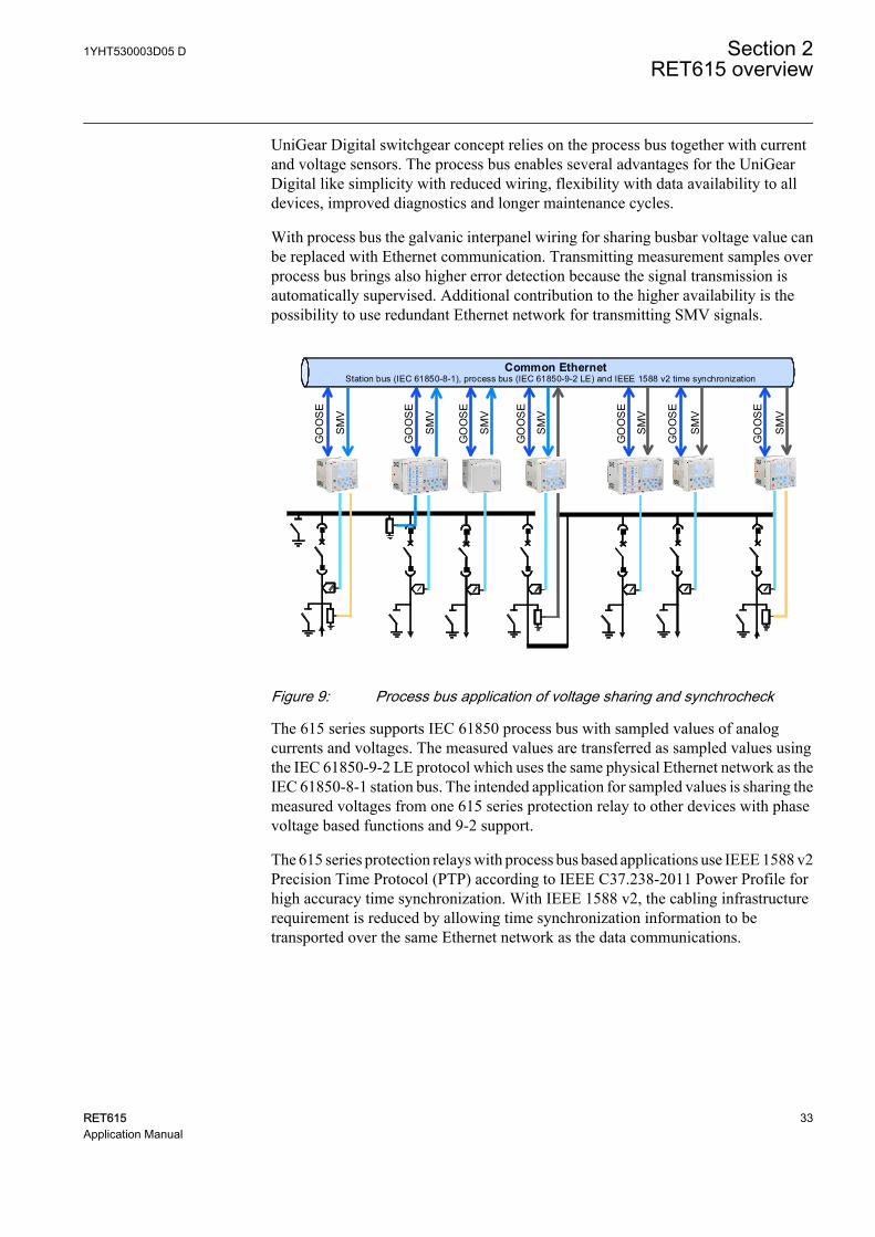
UniGear Digital switchgear concept relies on the process bus together with currentand voltage sensors. The process bus enables several advantages for the UniGearDigital like simplicity with reduced wiring, flexibility with data availability to alldevices, improved diagnostics and longer maintenance cycles.
With process bus the galvanic interpanel wiring for sharing busbar voltage value canbe replaced with Ethernet communication. Transmitting measurement samples overprocess bus brings also higher error detection because the signal transmission isautomatically supervised. Additional contribution to the higher availability is thepossibility to use redundant Ethernet network for transmitting SMV signals.
Common EthernetStation bus (IEC 61850-8-1), process bus (IEC 61850-9-2 LE) and IEEE 1588 v2 time synchronization
GO
OS
E
SM
V
GO
OS
E
SM
V
SM
V
GO
OS
E
GO
OS
E
SM
V
GO
OS
E
SM
V
SM
V
GO
OS
E
SM
V
GO
OS
E
GUID-2371EFA7-4369-4F1A-A23F-CF0CE2D474D3 V5 EN
Figure 9: Process bus application of voltage sharing and synchrocheck
The 615 series supports IEC 61850 process bus with sampled values of analogcurrents and voltages. The measured values are transferred as sampled values usingthe IEC 61850-9-2 LE protocol which uses the same physical Ethernet network as theIEC 61850-8-1 station bus. The intended application for sampled values is sharing themeasured voltages from one 615 series protection relay to other devices with phasevoltage based functions and 9-2 support.
The 615 series protection relays with process bus based applications use IEEE 1588 v2Precision Time Protocol (PTP) according to IEEE C37.238-2011 Power Profile forhigh accuracy time synchronization. With IEEE 1588 v2, the cabling infrastructurerequirement is reduced by allowing time synchronization information to betransported over the same Ethernet network as the data communications.
1YHT530003D05 D Section 2RET615 overview
RET615 33Application Manual
IEC 61850
HSR
SMV
tra
ffic
Backup 1588
master clock
Managed HSR
Ethernet
switch
Primary
IEEE 1588 v2
master clock
Secondary
IEEE 1588 v2
master clock
(optional)
Managed HSR
Ethernet
switch
GUID-7C56BC1F-F1B2-4E74-AB8E-05001A88D53D V5 EN
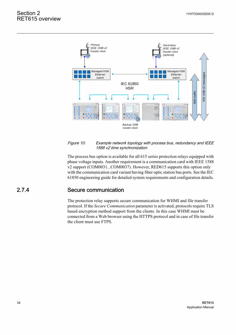
Figure 10: Example network topology with process bus, redundancy and IEEE1588 v2 time synchronization
The process bus option is available for all 615 series protection relays equipped withphase voltage inputs. Another requirement is a communication card with IEEE 1588v2 support (COM0031...COM0037). However, RED615 supports this option onlywith the communication card variant having fiber optic station bus ports. See the IEC61850 engineering guide for detailed system requirements and configuration details.
2.7.4 Secure communication
The protection relay supports secure communication for WHMI and file transferprotocol. If the Secure Communication parameter is activated, protocols require TLSbased encryption method support from the clients. In this case WHMI must beconnected from a Web browser using the HTTPS protocol and in case of file transferthe client must use FTPS.
Section 2 1YHT530003D05 DRET615 overview
34 RET615Application Manual
Section 3 RET615 standard configurations
3.1 Standard configurations
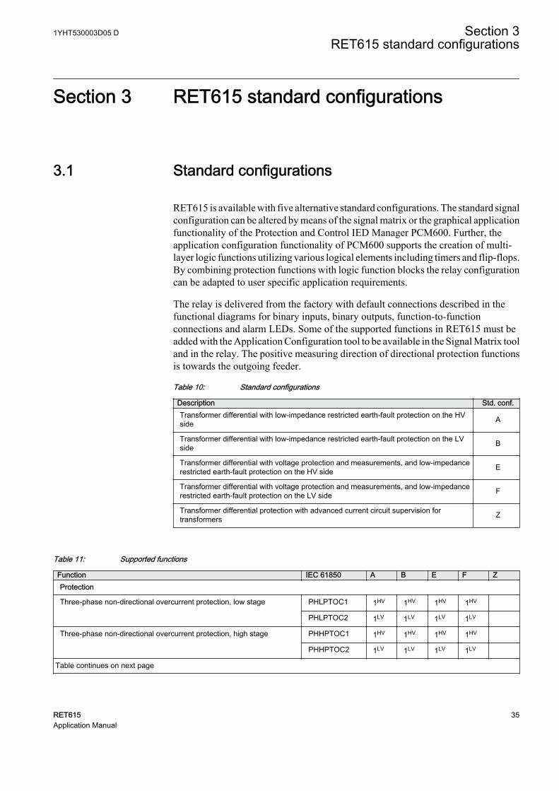
RET615 is available with five alternative standard configurations. The standard signalconfiguration can be altered by means of the signal matrix or the graphical applicationfunctionality of the Protection and Control IED Manager PCM600. Further, theapplication configuration functionality of PCM600 supports the creation of multi-layer logic functions utilizing various logical elements including timers and flip-flops.By combining protection functions with logic function blocks the relay configurationcan be adapted to user specific application requirements.
The relay is delivered from the factory with default connections described in thefunctional diagrams for binary inputs, binary outputs, function-to-functionconnections and alarm LEDs. Some of the supported functions in RET615 must beadded with the Application Configuration tool to be available in the Signal Matrix tooland in the relay. The positive measuring direction of directional protection functionsis towards the outgoing feeder.
Table 10: Standard configurations
Description Std. conf.Transformer differential with low-impedance restricted earth-fault protection on the HVside A
Transformer differential with low-impedance restricted earth-fault protection on the LVside B
Transformer differential with voltage protection and measurements, and low-impedancerestricted earth-fault protection on the HV side E
Transformer differential with voltage protection and measurements, and low-impedancerestricted earth-fault protection on the LV side F
Transformer differential protection with advanced current circuit supervision fortransformers Z
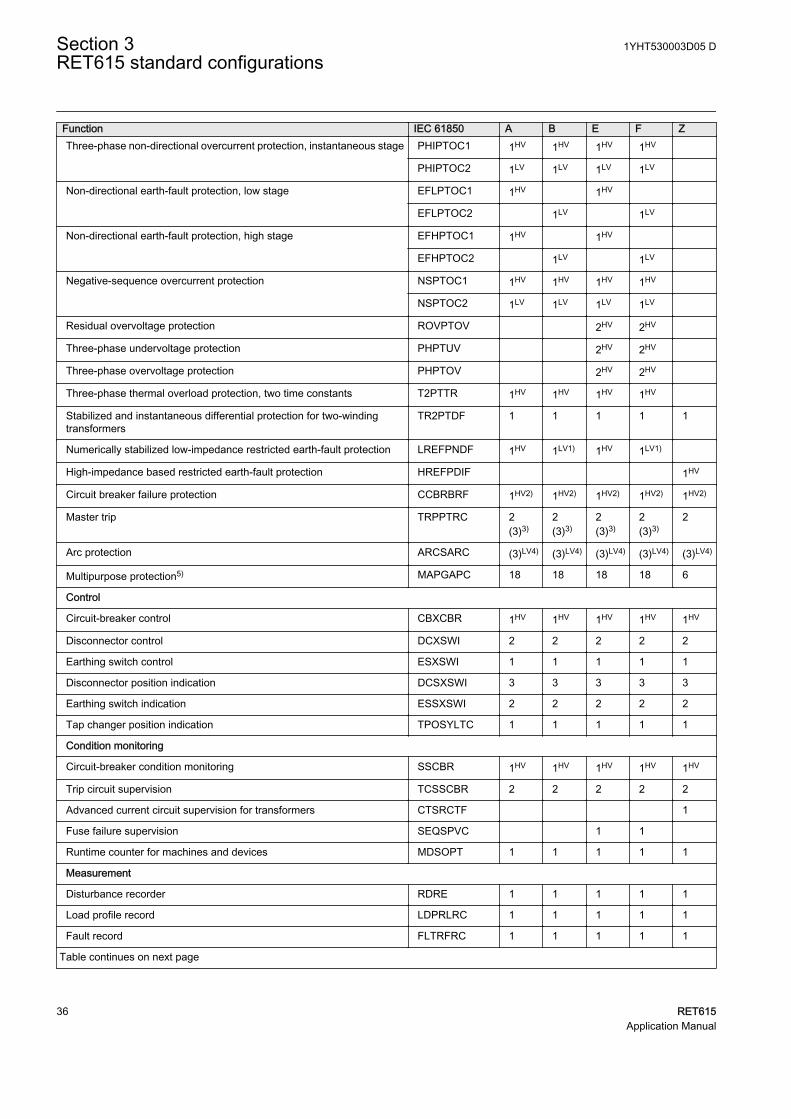
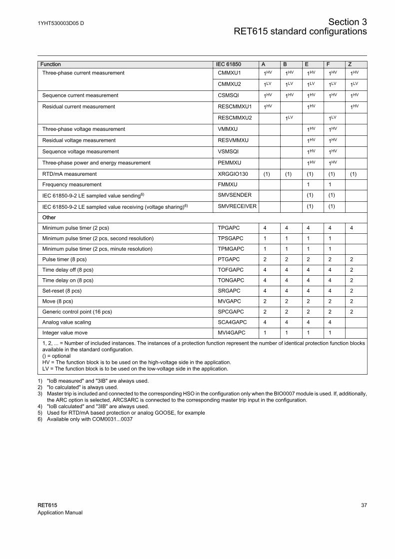
Table 11: Supported functions
Function IEC 61850 A B E F ZProtection
Three-phase non-directional overcurrent protection, low stage PHLPTOC1 1HV 1HV 1HV 1HV
PHLPTOC2 1LV 1LV 1LV 1LV
Three-phase non-directional overcurrent protection, high stage PHHPTOC1 1HV 1HV 1HV 1HV
PHHPTOC2 1LV 1LV 1LV 1LV
Table continues on next page
1YHT530003D05 D Section 3RET615 standard configurations
RET615 35Application Manual
Function IEC 61850 A B E F ZThree-phase non-directional overcurrent protection, instantaneous stage PHIPTOC1 1HV 1HV 1HV 1HV
PHIPTOC2 1LV 1LV 1LV 1LV
Non-directional earth-fault protection, low stage EFLPTOC1 1HV 1HV
EFLPTOC2 1LV 1LV
Non-directional earth-fault protection, high stage EFHPTOC1 1HV 1HV
EFHPTOC2 1LV 1LV
Negative-sequence overcurrent protection NSPTOC1 1HV 1HV 1HV 1HV
NSPTOC2 1LV 1LV 1LV 1LV
Residual overvoltage protection ROVPTOV 2HV 2HV
Three-phase undervoltage protection PHPTUV 2HV 2HV
Three-phase overvoltage protection PHPTOV 2HV 2HV
Three-phase thermal overload protection, two time constants T2PTTR 1HV 1HV 1HV 1HV
Stabilized and instantaneous differential protection for two-windingtransformers
TR2PTDF 1 1 1 1 1
Numerically stabilized low-impedance restricted earth-fault protection LREFPNDF 1HV 1LV1) 1HV 1LV1)
High-impedance based restricted earth-fault protection HREFPDIF 1HV
Circuit breaker failure protection CCBRBRF 1HV2) 1HV2) 1HV2) 1HV2) 1HV2)
Master trip TRPPTRC 2(3)3)
2(3)3)
2(3)3)
2(3)3)
2
Arc protection ARCSARC (3)LV4) (3)LV4) (3)LV4) (3)LV4) (3)LV4)
Multipurpose protection5) MAPGAPC 18 18 18 18 6
Control
Circuit-breaker control CBXCBR 1HV 1HV 1HV 1HV 1HV
Disconnector control DCXSWI 2 2 2 2 2
Earthing switch control ESXSWI 1 1 1 1 1
Disconnector position indication DCSXSWI 3 3 3 3 3
Earthing switch indication ESSXSWI 2 2 2 2 2
Tap changer position indication TPOSYLTC 1 1 1 1 1
Condition monitoring
Circuit-breaker condition monitoring SSCBR 1HV 1HV 1HV 1HV 1HV
Trip circuit supervision TCSSCBR 2 2 2 2 2
Advanced current circuit supervision for transformers CTSRCTF 1
Fuse failure supervision SEQSPVC 1 1
Runtime counter for machines and devices MDSOPT 1 1 1 1 1
Measurement
Disturbance recorder RDRE 1 1 1 1 1
Load profile record LDPRLRC 1 1 1 1 1
Fault record FLTRFRC 1 1 1 1 1
Table continues on next page
Section 3 1YHT530003D05 DRET615 standard configurations
36 RET615Application Manual
Function IEC 61850 A B E F ZThree-phase current measurement CMMXU1 1HV 1HV 1HV 1HV 1HV
CMMXU2 1LV 1LV 1LV 1LV 1LV
Sequence current measurement CSMSQI 1HV 1HV 1HV 1HV 1HV
Residual current measurement RESCMMXU1 1HV 1HV 1HV
RESCMMXU2 1LV 1LV
Three-phase voltage measurement VMMXU 1HV 1HV
Residual voltage measurement RESVMMXU 1HV 1HV
Sequence voltage measurement VSMSQI 1HV 1HV
Three-phase power and energy measurement PEMMXU 1HV 1HV
RTD/mA measurement XRGGIO130 (1) (1) (1) (1) (1)
Frequency measurement FMMXU 1 1
IEC 61850-9-2 LE sampled value sending6) SMVSENDER (1) (1)
IEC 61850-9-2 LE sampled value receiving (voltage sharing)6) SMVRECEIVER (1) (1)
Other
Minimum pulse timer (2 pcs) TPGAPC 4 4 4 4 4
Minimum pulse timer (2 pcs, second resolution) TPSGAPC 1 1 1 1
Minimum pulse timer (2 pcs, minute resolution) TPMGAPC 1 1 1 1
Pulse timer (8 pcs) PTGAPC 2 2 2 2 2
Time delay off (8 pcs) TOFGAPC 4 4 4 4 2
Time delay on (8 pcs) TONGAPC 4 4 4 4 2
Set-reset (8 pcs) SRGAPC 4 4 4 4 2
Move (8 pcs) MVGAPC 2 2 2 2 2
Generic control point (16 pcs) SPCGAPC 2 2 2 2 2
Analog value scaling SCA4GAPC 4 4 4 4
Integer value move MVI4GAPC 1 1 1 1
1, 2, ... = Number of included instances. The instances of a protection function represent the number of identical protection function blocksavailable in the standard configuration.() = optionalHV = The function block is to be used on the high-voltage side in the application.LV = The function block is to be used on the low-voltage side in the application.
1) "IoB measured" and "3IB" are always used.2) "Io calculated" is always used.3) Master trip is included and connected to the corresponding HSO in the configuration only when the BIO0007 module is used. If, additionally,
the ARC option is selected, ARCSARC is connected to the corresponding master trip input in the configuration.4) "IoB calculated" and "3IB" are always used.5) Used for RTD/mA based protection or analog GOOSE, for example6) Available only with COM0031...0037
1YHT530003D05 D Section 3RET615 standard configurations
RET615 37Application Manual
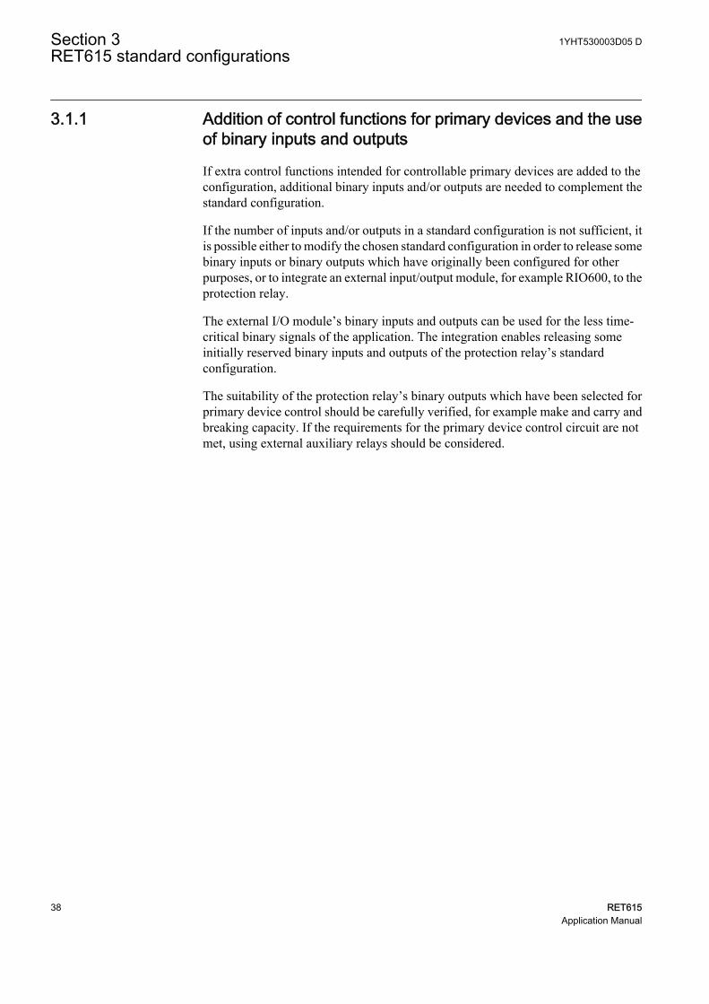
3.1.1 Addition of control functions for primary devices and the useof binary inputs and outputs
If extra control functions intended for controllable primary devices are added to theconfiguration, additional binary inputs and/or outputs are needed to complement thestandard configuration.
If the number of inputs and/or outputs in a standard configuration is not sufficient, itis possible either to modify the chosen standard configuration in order to release somebinary inputs or binary outputs which have originally been configured for otherpurposes, or to integrate an external input/output module, for example RIO600, to theprotection relay.
The external I/O module’s binary inputs and outputs can be used for the less time-critical binary signals of the application. The integration enables releasing someinitially reserved binary inputs and outputs of the protection relay’s standardconfiguration.
The suitability of the protection relay’s binary outputs which have been selected forprimary device control should be carefully verified, for example make and carry andbreaking capacity. If the requirements for the primary device control circuit are notmet, using external auxiliary relays should be considered.
Section 3 1YHT530003D05 DRET615 standard configurations
38 RET615Application Manual
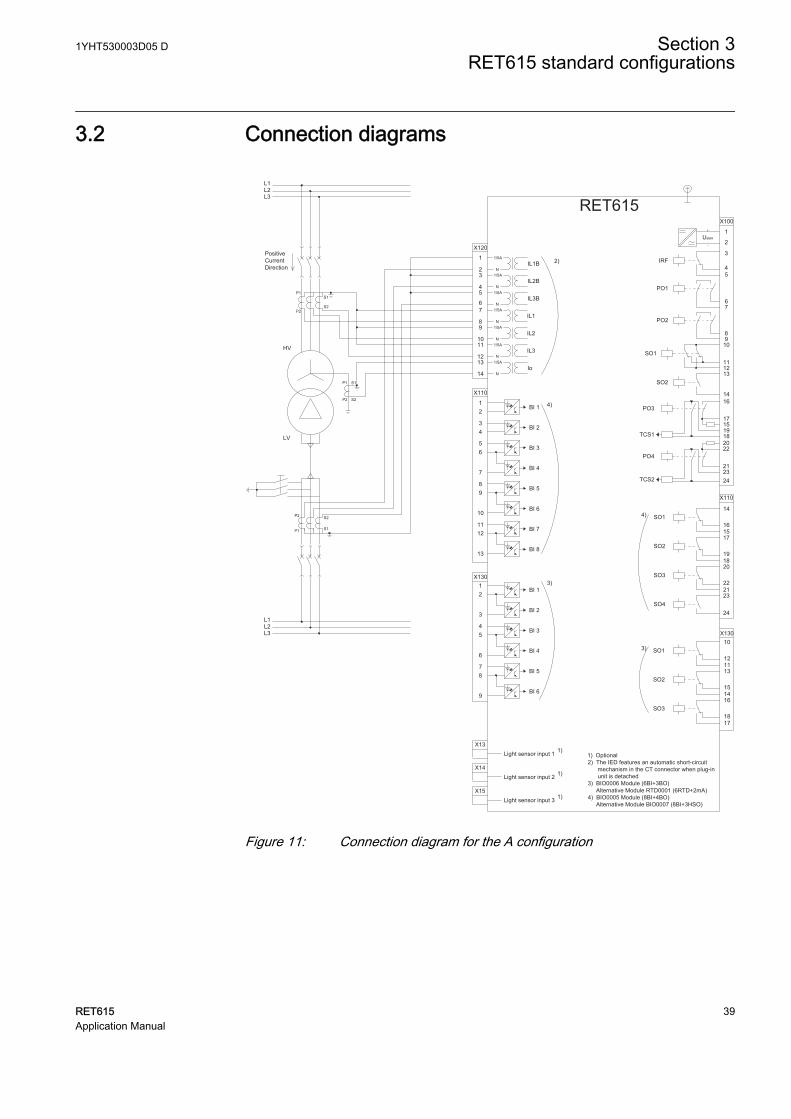
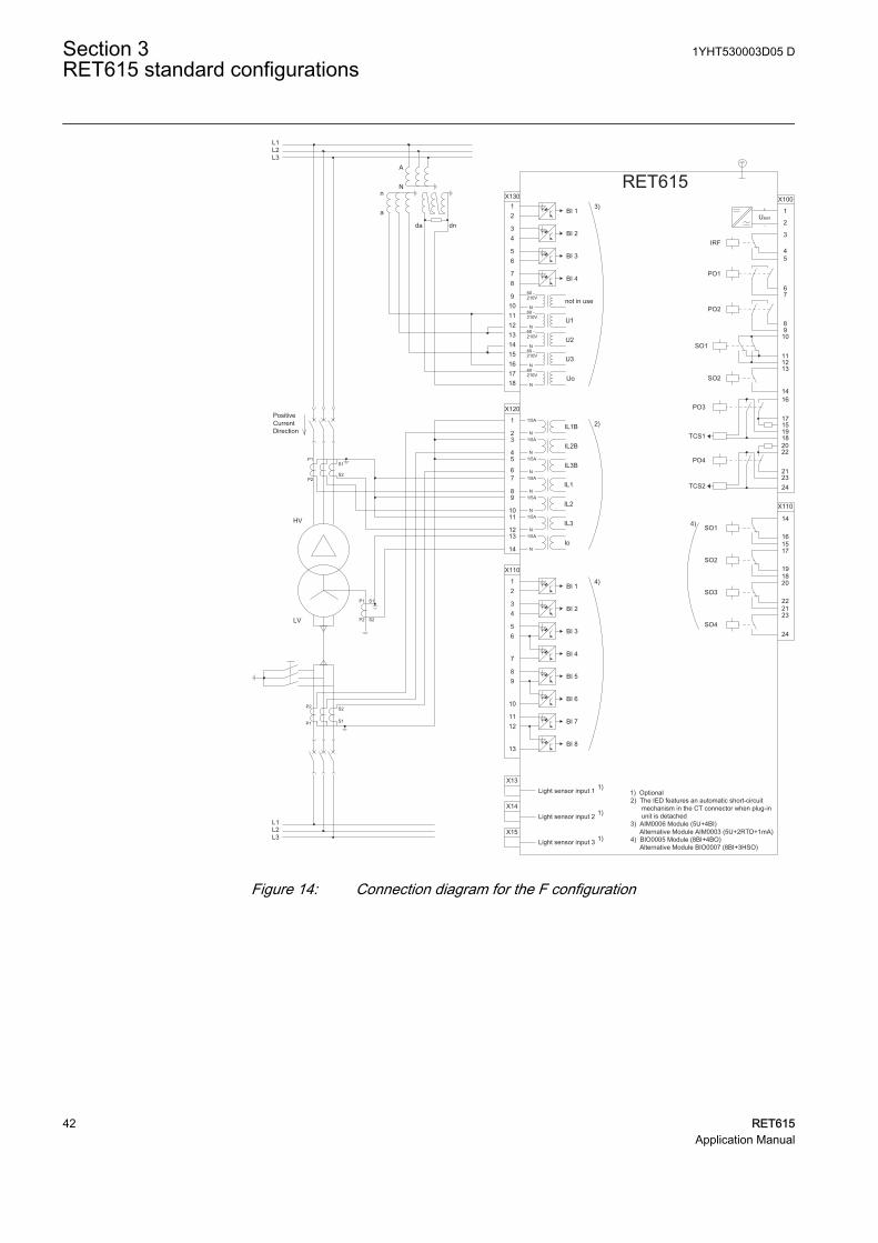
3.2 Connection diagrams
RET615
X13Light sensor input 1 1)
X14Light sensor input 2 1)
X15Light sensor input 3 1)
1) Optional2) The IED features an automatic short-circuit mechanism in the CT connector when plug-in unit is detached3) BIO0006 Module (6BI+3BO) Alternative Module RTD0001 (6RTD+2mA)4) BIO0005 Module (8BI+4BO) Alternative Module BIO0007 (8BI+3HSO)
16
17
1918
X100
67
8910
111213
15
14
2
1
3
45
22
212324
SO2
TCS2
PO4
SO1
TCS1
PO3
PO2
PO1
IRF
Uaux
20
X13012
3
45
6BI 4
BI 3
BI 2
BI 1
BI 6
BI 58
9
7
X130
12
10
11
15
13
14
18
16
17
SO3
SO2
SO1
3)
3)
L1L2L3
S1
S2
P1
P2
X110
34
56
7
89
10BI 6
BI 5
BI 4
BI 3
BI 2
BI 8
BI 712
13
11
BI 112
X110
16
14
15
19
17
18
22
20
21
SO3
SO2
SO1
23SO4
24
2)PositiveCurrentDirection
X120
1
23
45
67
89
1011
1213
14
IL1B1/5A
N
IL2B
IL3B
IL1
IL2
IL3
Io
1/5A
N1/5A
N1/5A
N1/5A
N1/5A
N1/5A
N
S1
S2
S2
S1P1
P2
P1
P2
L1L2L3
LV
HV
4)
4)
GUID-89E42CDB-6868-4D72-A6E4-E817D9B375C4 V1 EN
Figure 11: Connection diagram for the A configuration
1YHT530003D05 D Section 3RET615 standard configurations
RET615 39Application Manual
RET615
X13Light sensor input 1 1)
X14Light sensor input 2 1)
X15Light sensor input 3 1)
16
17
1918
X100
67
8910
111213
15
14
2
1
3
45
22
212324
SO2
TCS2
PO4
SO1
TCS1
PO3
PO2
PO1
IRF
Uaux
20
X13012
3
45
6BI 4
BI 3
BI 2
BI 1
BI 6
BI 58
9
7
X130
12
10
11
15
13
14
18
16
17
SO3
SO2
SO1
3)
3)
L1L2L3
S1
S2
P1
P2
X110
34
56
7
89
10BI 6
BI 5
BI 4
BI 3
BI 2
BI 8
BI 712
13
11
BI 112
X110
16
14
15
19
17
18
22
20
21
SO3
SO2
SO1
23SO4
24
2)PositiveCurrentDirection
X120
1
23
45
67
89
1011
1213
14
IL1B1/5A
N
IL2B
IL3B
IL1
IL2
IL3
Io
1/5A
N1/5A
N1/5A
N1/5A
N1/5A
N1/5A
N
S1
S2
S2
S1P1
P2
P1
P2
L1L2L3
LV
HV
4)
4)
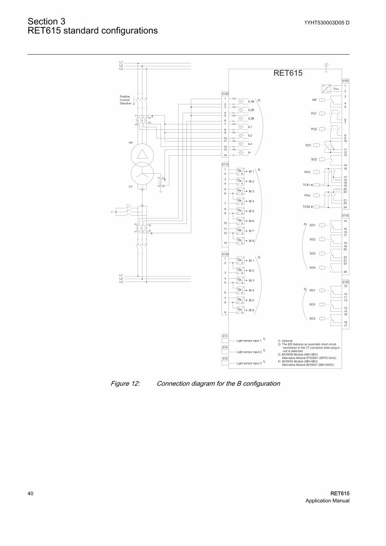
1) Optional2) The IED features an automatic short-circuit mechanism in the CT connector when plug-in unit is detached3) BIO0006 Module (6BI+3BO) Alternative Module RTD0001 (6RTD+2mA)4) BIO0005 Module (8BI+4BO) Alternative Module BIO0007 (8BI+3HSO)
GUID-3974F084-39AE-4491-AD67-739BBBB5611D V1 EN
Figure 12: Connection diagram for the B configuration
Section 3 1YHT530003D05 DRET615 standard configurations
40 RET615Application Manual
RET615
X13Light sensor input 1 1)
X14Light sensor input 2 1)
X15Light sensor input 3 1)
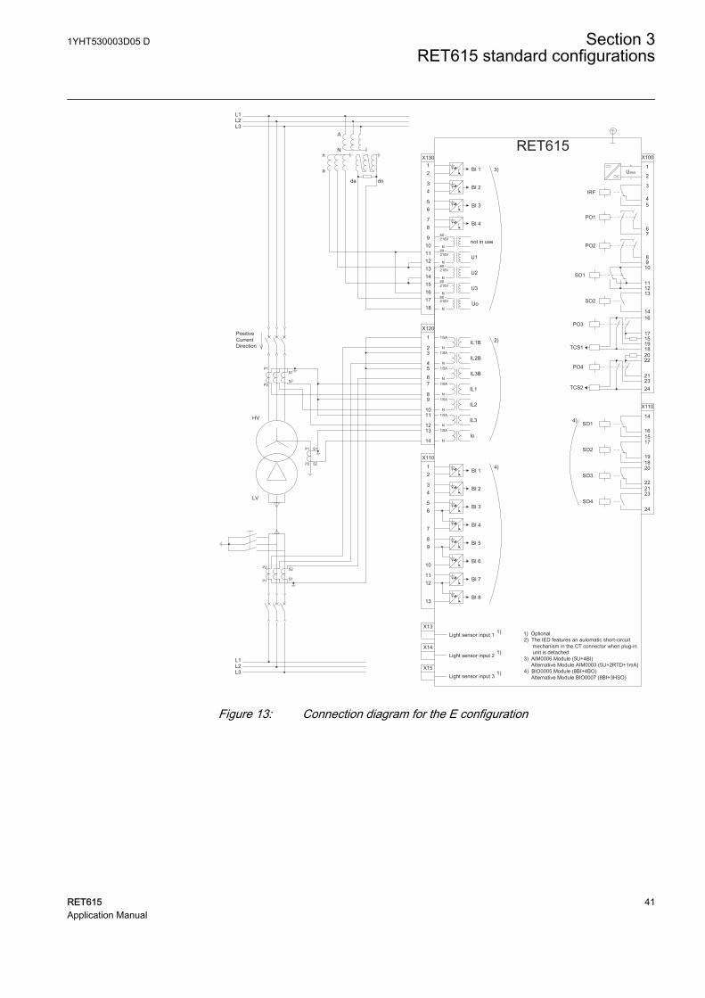
1) Optional2) The IED features an automatic short-circuit mechanism in the CT connector when plug-in unit is detached3) AIM0006 Module (5U+4BI) Alternative Module AIM0003 (5U+2RTD+1mA)4) BIO0005 Module (8BI+4BO) Alternative Module BIO0007 (8BI+3HSO)
16
17
1918
X100
67
8910
111213
15
14
2
1
3
45
22
212324
SO2
TCS2
PO4
SO1
TCS1
PO3
PO2
PO1
IRF
Uaux
20
L1L2L3
S1
S2
P1
P2
X110
34
56
7
89
10BI 6
BI 5
BI 4
BI 3
BI 2
BI 8
BI 712
13
11
BI 112
X110
16
14
15
19
17
18
22
20
21
SO3
SO2
SO1
23SO4
24
2)PositiveCurrentDirection
X120
1
23
45
67
89
1011
1213
14
IL1B1/5A
N
IL2B
IL3B
IL1
IL2
IL3
Io
1/5A
N1/5A
N1/5A
N1/5A
N1/5A
N1/5A
N
S1
S2
S2
S1P1
P2
P1
P2
L1L2L3
LV
HV
da dn
a
nN
A
X13012
34
56
BI 4
BI 3
BI 2
BI 1
87
9101112
not in use
1314
U1
1516
U2
1718
U3
UoN
N
N
N
60 -
N
210V
60 -210V
60 -210V
60 -210V
60 -210V
4)
3)
4)
GUID-8279E135-B80A-4A5F-89BD-6A06EB4191CF V1 EN
Figure 13: Connection diagram for the E configuration
1YHT530003D05 D Section 3RET615 standard configurations
RET615 41Application Manual
RET615
X13Light sensor input 1 1)
X14Light sensor input 2 1)
X15Light sensor input 3 1)
16
17
1918
X100
67
8910
111213
15
14
2
1
3
45
22
212324
SO2
TCS2
PO4
SO1
TCS1
PO3
PO2
PO1
IRF
Uaux
20
L1L2L3
S1
S2
P1
P2
X110
34
56
7
89
10BI 6
BI 5
BI 4
BI 3
BI 2
BI 8
BI 712
13
11
BI 112
X110
16
14
15
19
17
18
22
20
21
SO3
SO2
SO1
23SO4
24
2)PositiveCurrentDirection
X120
1
23
45
67
89
1011
1213
14
IL1B1/5A
N
IL2B
IL3B
IL1
IL2
IL3
Io
1/5A
N1/5A
N1/5A
N1/5A
N1/5A
N1/5A
N
S1
S2
S2
S1P1
P2
P1
P2
L1L2L3
LV
HV
da dn
a
nN
A
X13012
34
56
BI 4
BI 3
BI 2
BI 1
87
9101112
not in use
1314
U1
1516
U2
1718
U3
UoN
N
N
N
60 -
N
210V
60 -210V
60 -210V
60 -210V
60 -210V
4)
3)
4)
1) Optional2) The IED features an automatic short-circuit mechanism in the CT connector when plug-in unit is detached3) AIM0006 Module (5U+4BI) Alternative Module AIM0003 (5U+2RTD+1mA)4) BIO0005 Module (8BI+4BO) Alternative Module BIO0007 (8BI+3HSO)
GUID-3347EC9C-306D-4D50-B988-EEE12285AF2E V1 EN
Figure 14: Connection diagram for the F configuration
Section 3 1YHT530003D05 DRET615 standard configurations
42 RET615Application Manual
X110
34
56
7
89
10BI 6
BI 5
BI 4
BI 3
BI 2
BI 8
BI 712
13
11
BI 112
X110
16
14
15
19
17
18
22
20
21
SO3
SO2
SO1
23SO4
24
X13Light sensor input 1 1)
X14Light sensor input 2 1)
X15Light sensor input 3 1)
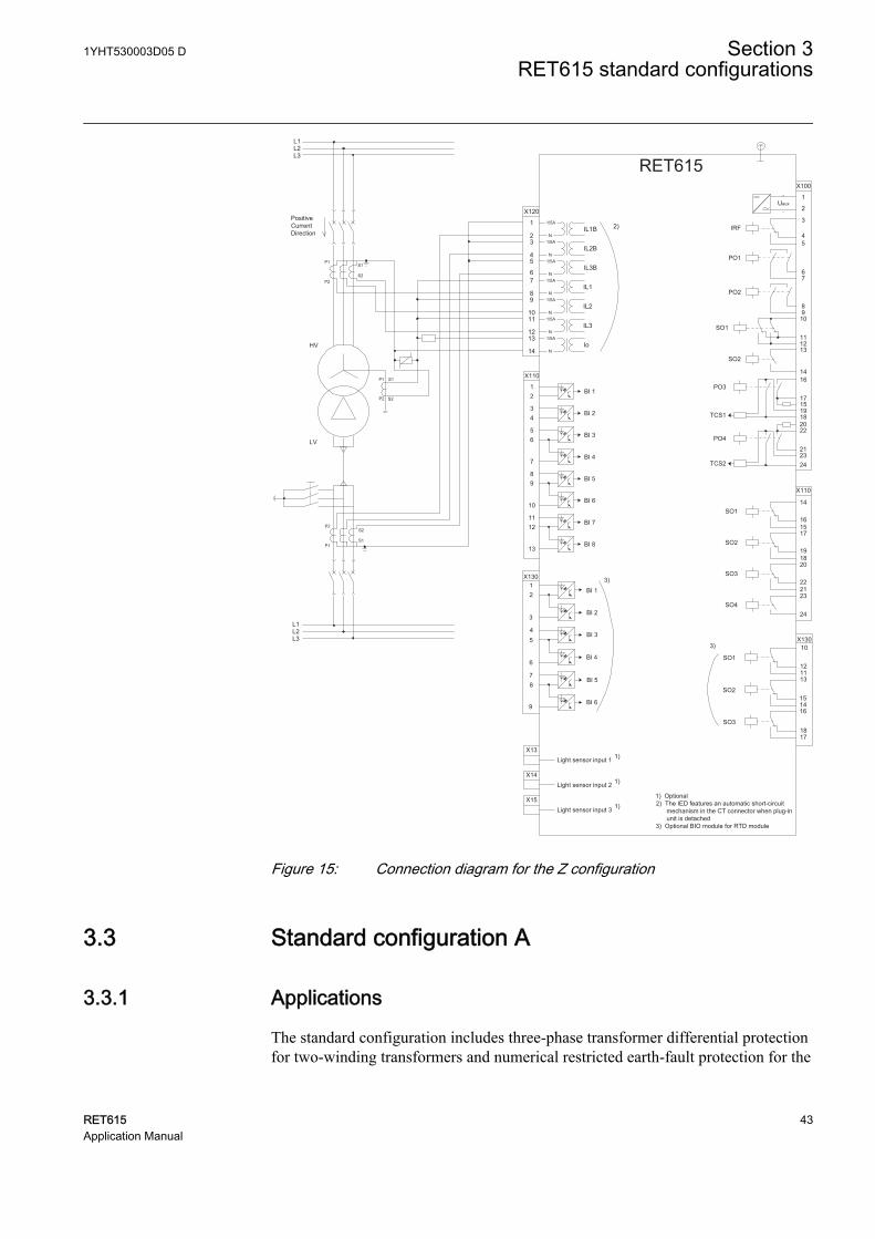
1) Optional2) The IED features an automatic short-circuit mechanism in the CT connector when plug-in unit is detached3) Optional BIO module for RTD module
L1L2L3
L1L2L3
PositiveCurrentDirection
S1
S2
P1
P2
LV
HV
S2
S1
P2
P1
S1
S2
P1
P2
RET615
16
17
1918
X100
67
8910
111213
15
14
2
1
3
45
22
212324
SO2
TCS2
PO4
SO1
TCS1
PO3
PO2
PO1
IRF
Uaux
20
3
45
6
78
9
12
BI 6
BI 5
BI 4
BI 3
BI 2
BI 13)
3)
SO3
SO2
SO1
X13010
121113
151416
1817
X130
2)
X120
1
23
45
67
89
1011
1213
14
IL1B1/5A
N
IL2B
IL3B
IL1
IL2
IL3
Io
1/5A
N1/5A
N1/5A
N1/5A
N1/5A
N1/5A
N
GUID-9BCBB45F-0F62-45E4-B9C1-70FCF53BFF7A V1 EN
Figure 15: Connection diagram for the Z configuration
3.3 Standard configuration A
3.3.1 Applications
The standard configuration includes three-phase transformer differential protectionfor two-winding transformers and numerical restricted earth-fault protection for the
1YHT530003D05 D Section 3RET615 standard configurations
RET615 43Application Manual
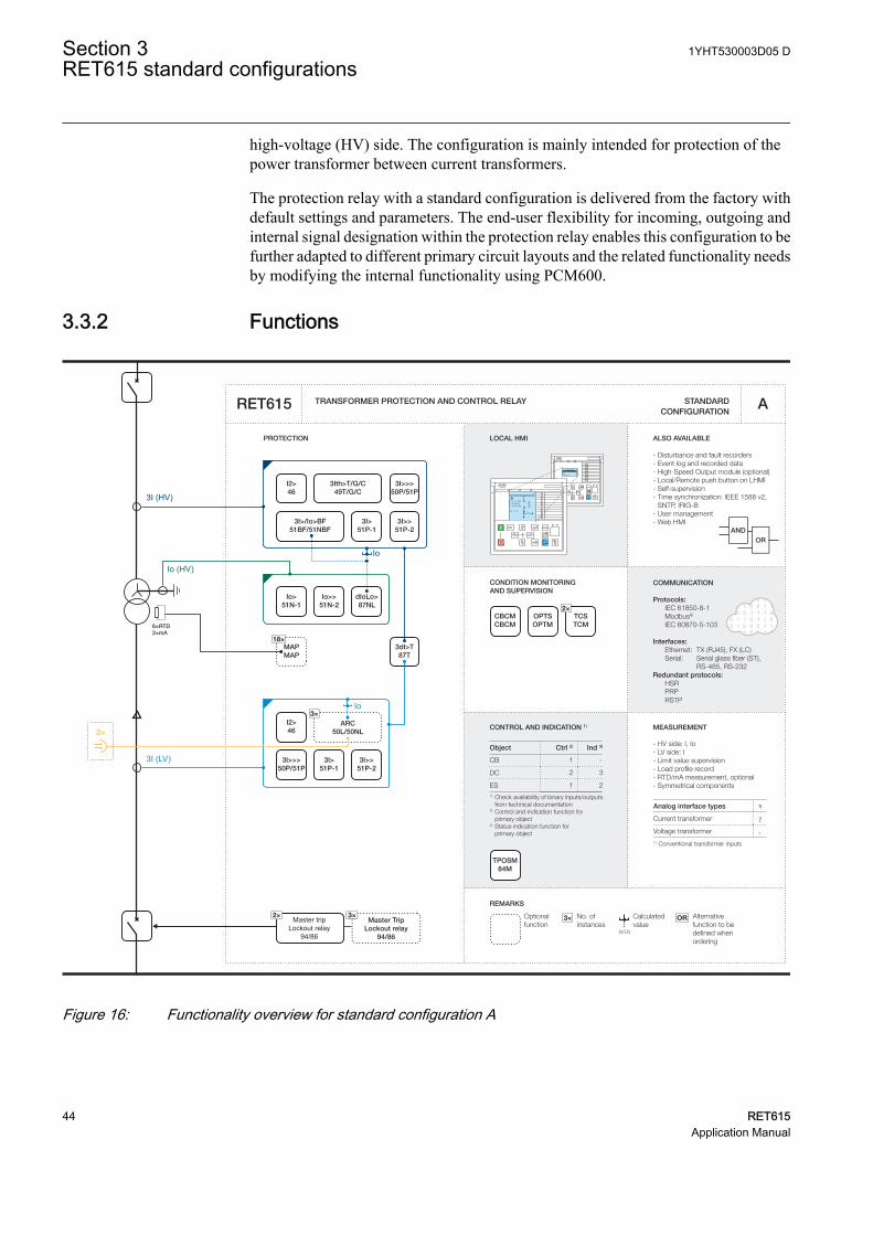
high-voltage (HV) side. The configuration is mainly intended for protection of thepower transformer between current transformers.
The protection relay with a standard configuration is delivered from the factory withdefault settings and parameters. The end-user flexibility for incoming, outgoing andinternal signal designation within the protection relay enables this configuration to befurther adapted to different primary circuit layouts and the related functionality needsby modifying the internal functionality using PCM600.
3.3.2 Functions
Master tripLockout relay
94/86
Master TripLockout relay
94/86
3×2×
6×RTD2×mA
CONDITION MONITORING AND SUPERVISION
ALSO AVAILABLE
- Disturbance and fault recorders- Event log and recorded data- High-Speed Output module (optional)- Local/Remote push button on LHMI- Self-supervision- Time synchronization: IEEE 1588 v2,
SNTP, IRIG-B- User management- Web HMI
CONTROL AND INDICATION 1) MEASUREMENT
TRANSFORMER PROTECTION AND CONTROL RELAY
PROTECTION LOCAL HMI
Object Ctrl 2) Ind 3)
CB
DC
ES1) Check availability of binary inputs/outputs
from technical documentation2) Control and indication function for
primary object3) Status indication function for primary object
1 -
2 3
1 2
STANDARD CONFIGURATION
REMARKS
Optionalfunction
No. ofinstances
Alternative function to be defined when ordering
OR
Io/Uo
Calculatedvalue
3×
RL
ClearESCI
O
Configuration ASystemHMITimeAuthorization
RL
ClearESCI
O
U12 0. 0 kVP 0.00 kWQ 0.00 kVAr
IL2 0 A
A
COMMUNICATION
Protocols: IEC 61850-8-1 Modbus®
IEC 60870-5-103 Interfaces: Ethernet: TX (RJ45), FX (LC) Serial: Serial glass fiber (ST), RS-485, RS-232Redundant protocols: HSR PRP RSTP
RET615
ORAND
- HV side: I, Io - LV side: I- Limit value supervision- Load profile record- RTD/mA measurement, optional- Symmetrical components
Analog interface types 1)
Current transformer
1) Conventional transformer inputs
Voltage transformer
7
-
A
I2>46
3I>>>50P/51P
3I>/Io>BF51BF/51NBF
3I>51P-1
3I>>51P-2
3dI>T87T
I2>46
3×ARC
50L/50NL
2×TCSTCM
CBCMCBCM
OPTSOPTM
3I>>51P-2
3I>>>50P/51P
3I>51P-1
Io>51N-1
Io>>51N-2
dIoLo>87NL
18×MAPMAP
TPOSM84M
Io (HV)
Io
Io
3I (LV)
3×
3I (HV)
3Ith>T/G/C49T/G/C
GUID-B39DE639-6FC6-4A1B-8E16-DD9902758782 V1 EN
Figure 16: Functionality overview for standard configuration A
Section 3 1YHT530003D05 DRET615 standard configurations
44 RET615Application Manual
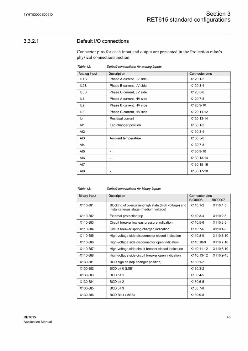
3.3.2.1 Default I/O connections
Connector pins for each input and output are presented in the Protection ralay'sphysical connections section.
Table 12: Default connections for analog inputs
Analog input Description Connector pinsIL1B Phase A current, LV side X120:1-2
IL2B Phase B current, LV side X120:3-4
IL3B Phase C current, LV side X120:5-6
IL1 Phase A current, HV side X120:7-8
IL2 Phase B current, HV side X120:9-10
IL3 Phase C current, HV side X120:11-12
Io Residual current X120:13-14
AI1 Tap changer position X130:1-2
AI2 - X130:3-4
AI3 Ambient temperature X130:5-6
AI4 - X130:7-8
AI5 - X130:9-10
AI6 - X130:13-14
AI7 - X130:15-16
AI8 - X130:17-18
Table 13: Default connections for binary inputs
Binary input Description Connector pinsBIO0005 BIO0007
X110-BI1 Blocking of overcurrent high state (high voltage) andinstantaneous stage (medium voltage)
X110:1-2 X110:1,5
X110-BI2 External protection trip X110:3-4 X110:2,5
X110-BI3 Circuit breaker low gas pressure indication X110:5-6 X110:3,5
X110-BI4 Circuit breaker spring charged indication X110:7-6 X110:4-5
X110-BI5 High-voltage side disconnector closed indication X110:8-9 X110:6,10
X110-BI6 High-voltage side disconnector open indication X110:10-9 X110:7,10
X110-BI7 High-voltage side circuit breaker closed indication X110:11-12 X110:8,10
X110-BI8 High-voltage side circuit breaker open indication X110:13-12 X110:9-10
X130-BI1 BCD sign bit (tap changer position) X130:1-2
X130-BI2 BCD bit 0 (LSB) X130:3-2
X130-BI3 BCD bit 1 X130:4-5
X130-BI4 BCD bit 2 X130:6-5
X130-BI5 BCD bit 3 X130:7-8
X130-BI6 BCD Bit 4 (MSB) X130:9-8
1YHT530003D05 D Section 3RET615 standard configurations
RET615 45Application Manual
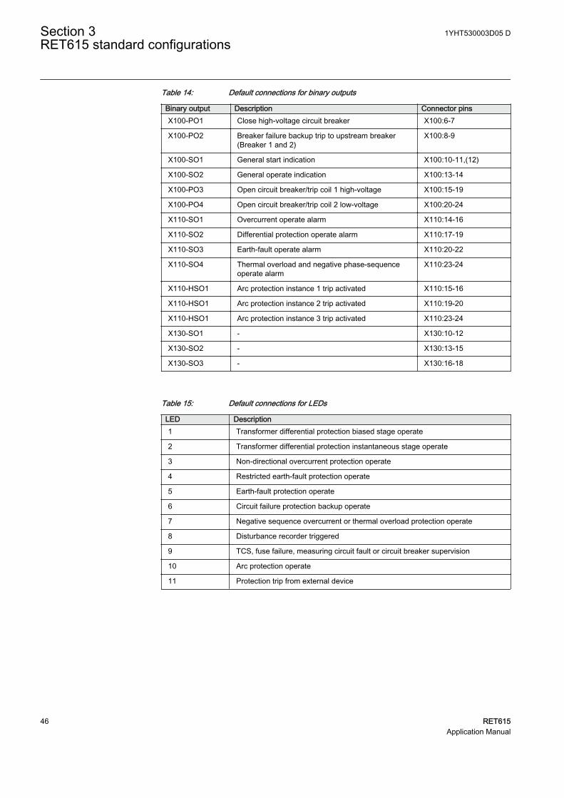
Table 14: Default connections for binary outputs
Binary output Description Connector pinsX100-PO1 Close high-voltage circuit breaker X100:6-7
X100-PO2 Breaker failure backup trip to upstream breaker(Breaker 1 and 2)
X100:8-9
X100-SO1 General start indication X100:10-11,(12)
X100-SO2 General operate indication X100:13-14
X100-PO3 Open circuit breaker/trip coil 1 high-voltage X100:15-19
X100-PO4 Open circuit breaker/trip coil 2 low-voltage X100:20-24
X110-SO1 Overcurrent operate alarm X110:14-16
X110-SO2 Differential protection operate alarm X110:17-19
X110-SO3 Earth-fault operate alarm X110:20-22
X110-SO4 Thermal overload and negative phase-sequenceoperate alarm
X110:23-24
X110-HSO1 Arc protection instance 1 trip activated X110:15-16
X110-HSO1 Arc protection instance 2 trip activated X110:19-20
X110-HSO1 Arc protection instance 3 trip activated X110:23-24
X130-SO1 - X130:10-12
X130-SO2 - X130:13-15
X130-SO3 - X130:16-18
Table 15: Default connections for LEDs
LED Description1 Transformer differential protection biased stage operate
2 Transformer differential protection instantaneous stage operate
3 Non-directional overcurrent protection operate
4 Restricted earth-fault protection operate
5 Earth-fault protection operate
6 Circuit failure protection backup operate
7 Negative sequence overcurrent or thermal overload protection operate
8 Disturbance recorder triggered
9 TCS, fuse failure, measuring circuit fault or circuit breaker supervision
10 Arc protection operate
11 Protection trip from external device
Section 3 1YHT530003D05 DRET615 standard configurations
46 RET615Application Manual
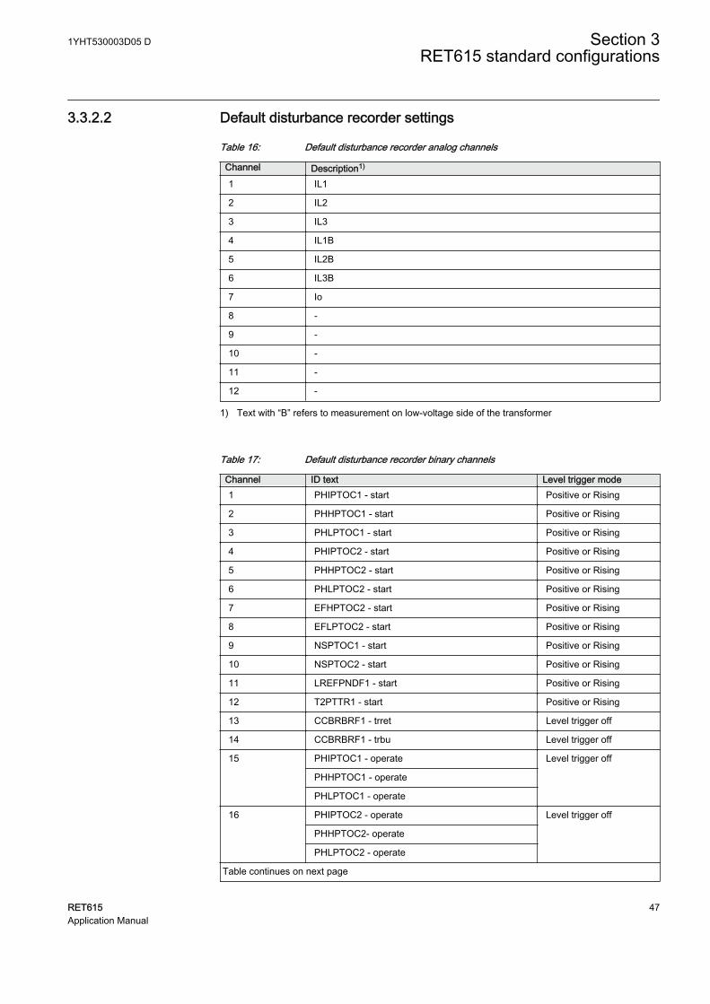
3.3.2.2 Default disturbance recorder settings
Table 16: Default disturbance recorder analog channels
Channel Description1)
1 IL1
2 IL2
3 IL3
4 IL1B
5 IL2B
6 IL3B
7 Io
8 -
9 -
10 -
11 -
12 -
1) Text with “B” refers to measurement on low-voltage side of the transformer
Table 17: Default disturbance recorder binary channels
Channel ID text Level trigger mode1 PHIPTOC1 - start Positive or Rising
2 PHHPTOC1 - start Positive or Rising
3 PHLPTOC1 - start Positive or Rising
4 PHIPTOC2 - start Positive or Rising
5 PHHPTOC2 - start Positive or Rising
6 PHLPTOC2 - start Positive or Rising
7 EFHPTOC2 - start Positive or Rising
8 EFLPTOC2 - start Positive or Rising
9 NSPTOC1 - start Positive or Rising
10 NSPTOC2 - start Positive or Rising
11 LREFPNDF1 - start Positive or Rising
12 T2PTTR1 - start Positive or Rising
13 CCBRBRF1 - trret Level trigger off
14 CCBRBRF1 - trbu Level trigger off
15 PHIPTOC1 - operate Level trigger off
PHHPTOC1 - operate
PHLPTOC1 - operate
16 PHIPTOC2 - operate Level trigger off
PHHPTOC2- operate
PHLPTOC2 - operate
Table continues on next page
1YHT530003D05 D Section 3RET615 standard configurations
RET615 47Application Manual
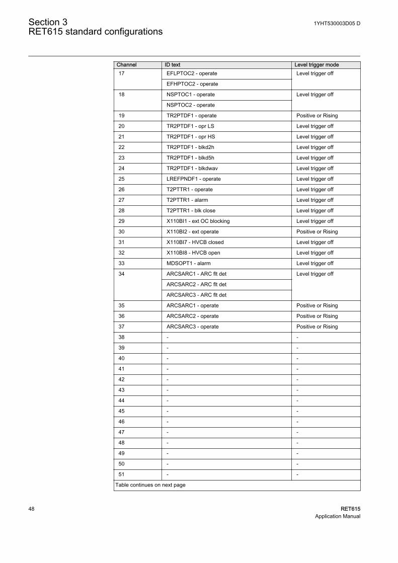
Channel ID text Level trigger mode17 EFLPTOC2 - operate Level trigger off
EFHPTOC2 - operate
18 NSPTOC1 - operate Level trigger off
NSPTOC2 - operate
19 TR2PTDF1 - operate Positive or Rising
20 TR2PTDF1 - opr LS Level trigger off
21 TR2PTDF1 - opr HS Level trigger off
22 TR2PTDF1 - blkd2h Level trigger off
23 TR2PTDF1 - blkd5h Level trigger off
24 TR2PTDF1 - blkdwav Level trigger off
25 LREFPNDF1 - operate Level trigger off
26 T2PTTR1 - operate Level trigger off
27 T2PTTR1 - alarm Level trigger off
28 T2PTTR1 - blk close Level trigger off
29 X110BI1 - ext OC blocking Level trigger off
30 X110BI2 - ext operate Positive or Rising
31 X110BI7 - HVCB closed Level trigger off
32 X110BI8 - HVCB open Level trigger off
33 MDSOPT1 - alarm Level trigger off
34 ARCSARC1 - ARC flt det Level trigger off
ARCSARC2 - ARC flt det
ARCSARC3 - ARC flt det
35 ARCSARC1 - operate Positive or Rising
36 ARCSARC2 - operate Positive or Rising
37 ARCSARC3 - operate Positive or Rising
38 - -
39 - -
40 - -
41 - -
42 - -
43 - -
44 - -
45 - -
46 - -
47 - -
48 - -
49 - -
50 - -
51 - -
Table continues on next page
Section 3 1YHT530003D05 DRET615 standard configurations
48 RET615Application Manual
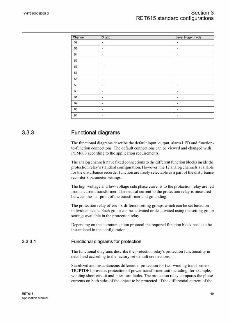
Channel ID text Level trigger mode52 - -
53 - -
54 - -
55 - -
56 - -
57 - -
58 - -
59 - -
60 - -
61 - -
62 - -
63 - -
64 - -
3.3.3 Functional diagrams
The functional diagrams describe the default input, output, alarm LED and function-to-function connections. The default connections can be viewed and changed withPCM600 according to the application requirements.
The analog channels have fixed connections to the different function blocks inside theprotection relay’s standard configuration. However, the 12 analog channels availablefor the disturbance recorder function are freely selectable as a part of the disturbancerecorder’s parameter settings.
The high-voltage and low-voltage side phase currents to the protection relay are fedfrom a current transformer. The neutral current to the protection relay is measuredbetween the star point of the transformer and grounding.
The protection relay offers six different setting groups which can be set based onindividual needs. Each group can be activated or deactivated using the setting groupsettings available in the protection relay.
Depending on the communication protocol the required function block needs to beinstantiated in the configuration.
3.3.3.1 Functional diagrams for protection
The functional diagrams describe the protection relay's protection functionality indetail and according to the factory set default connections.
Stabilized and instantaneous differential protection for two-winding transformersTR2PTDF1 provides protection of power transformer unit including, for example,winding short-circuit and inter-turn faults. The protection relay compares the phasecurrents on both sides of the object to be protected. If the differential current of the
1YHT530003D05 D Section 3RET615 standard configurations
RET615 49Application Manual
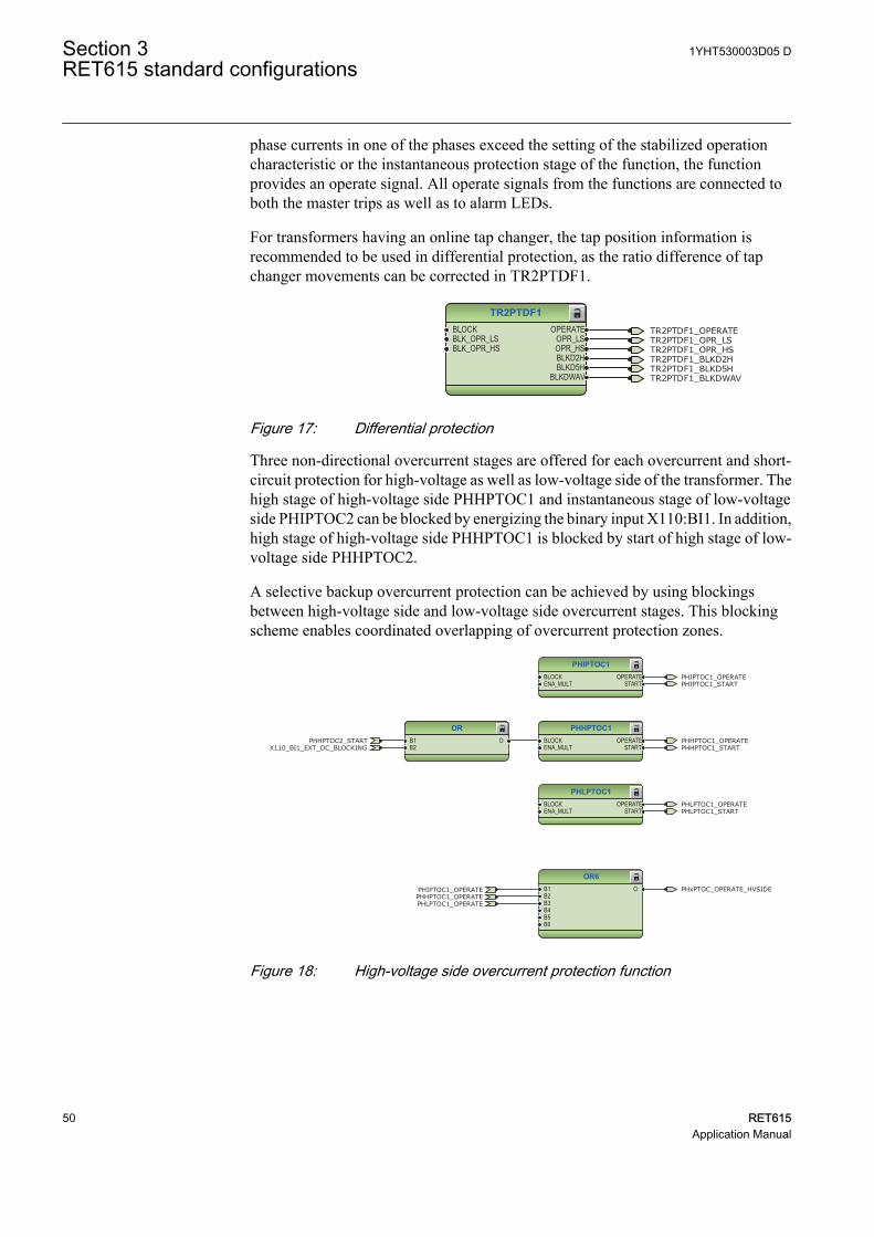
phase currents in one of the phases exceed the setting of the stabilized operationcharacteristic or the instantaneous protection stage of the function, the functionprovides an operate signal. All operate signals from the functions are connected toboth the master trips as well as to alarm LEDs.
For transformers having an online tap changer, the tap position information isrecommended to be used in differential protection, as the ratio difference of tapchanger movements can be corrected in TR2PTDF1.
TR2PTDF1BLOCKBLK_OPR_LSBLK_OPR_HS
OPERATEOPR_LSOPR_HSBLKD2HBLKD5H
BLKDWAV
TR2PTDF1_OPERATETR2PTDF1_OPR_LSTR2PTDF1_OPR_HSTR2PTDF1_BLKD2HTR2PTDF1_BLKD5HTR2PTDF1_BLKDWAV
GUID-8B315C2B-1B91-4A81-8B66-B988E1AFA537 V1 EN
Figure 17: Differential protection
Three non-directional overcurrent stages are offered for each overcurrent and short-circuit protection for high-voltage as well as low-voltage side of the transformer. Thehigh stage of high-voltage side PHHPTOC1 and instantaneous stage of low-voltageside PHIPTOC2 can be blocked by energizing the binary input X110:BI1. In addition,high stage of high-voltage side PHHPTOC1 is blocked by start of high stage of low-voltage side PHHPTOC2.
A selective backup overcurrent protection can be achieved by using blockingsbetween high-voltage side and low-voltage side overcurrent stages. This blockingscheme enables coordinated overlapping of overcurrent protection zones.
PHIPTOC1BLOCKENA_MULT
OPERATESTART
PHLPTOC1BLOCKENA_MULT
OPERATESTART
PHHPTOC1BLOCKENA_MULT
OPERATESTART
ORB1B2
O
OR6B1B2B3B4B5B6
O
PHIPTOC1_OPERATE
PHIPTOC1_OPERATE
PHLPTOC1_OPERATE
PHLPTOC1_OPERATE
PHHPTOC1_OPERATE
PHHPTOC1_OPERATE
PHIPTOC1_START
PHLPTOC1_START
PHHPTOC1_STARTPHHPTOC2_START
X110_BI1_EXT_OC_BLOCKING
PHxPTOC_OPERATE_HVSIDE
GUID-2918DC28-60D3-4C9A-9802-C6B9CAAD23D9 V1 EN
Figure 18: High-voltage side overcurrent protection function
Section 3 1YHT530003D05 DRET615 standard configurations
50 RET615Application Manual
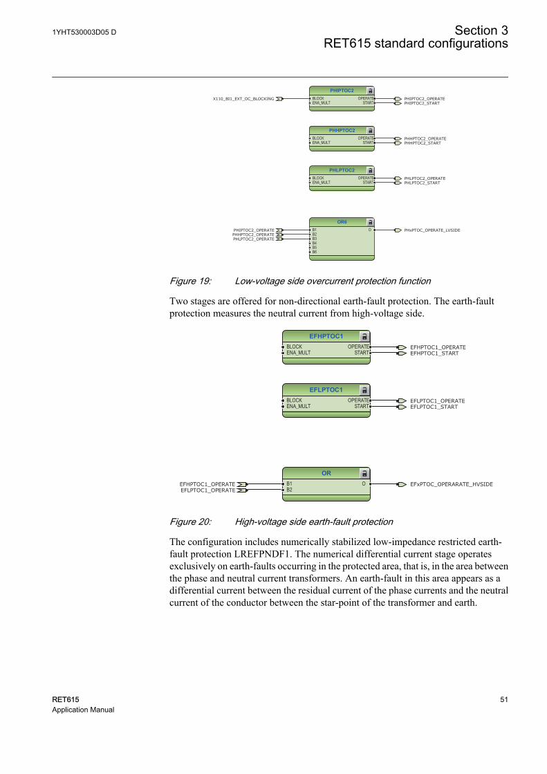
PHIPTOC2BLOCKENA_MULT
OPERATESTART
PHHPTOC2BLOCKENA_MULT
OPERATESTART
PHLPTOC2BLOCKENA_MULT
OPERATESTART
OR6B1B2B3B4B5B6
O
PHIPTOC2_OPERATE
PHIPTOC2_OPERATE
PHLPTOC2_OPERATE
PHLPTOC2_OPERATE
PHHPTOC2_OPERATE
PHHPTOC2_OPERATE
PHLPTOC2_START
PHIPTOC2_START
PHHPTOC2_START
X110_BI1_EXT_OC_BLOCKING
PHxPTOC_OPERATE_LVSIDE
GUID-855EE73B-C4E8-4029-8B45-6D301F48890C V1 EN
Figure 19: Low-voltage side overcurrent protection function
Two stages are offered for non-directional earth-fault protection. The earth-faultprotection measures the neutral current from high-voltage side.
EFHPTOC1BLOCKENA_MULT
OPERATESTART
EFLPTOC1BLOCKENA_MULT
OPERATESTART
ORB1B2
O
EFHPTOC1_OPERATE
EFHPTOC1_OPERATE
EFLPTOC1_OPERATE
EFLPTOC1_OPERATE
EFHPTOC1_START
EFLPTOC1_START
EFxPTOC_OPERARATE_HVSIDE
GUID-4B57E401-4A6C-4FB2-A49C-88D0C644BB00 V1 EN
Figure 20: High-voltage side earth-fault protection
The configuration includes numerically stabilized low-impedance restricted earth-fault protection LREFPNDF1. The numerical differential current stage operatesexclusively on earth-faults occurring in the protected area, that is, in the area betweenthe phase and neutral current transformers. An earth-fault in this area appears as adifferential current between the residual current of the phase currents and the neutralcurrent of the conductor between the star-point of the transformer and earth.
1YHT530003D05 D Section 3RET615 standard configurations
RET615 51Application Manual
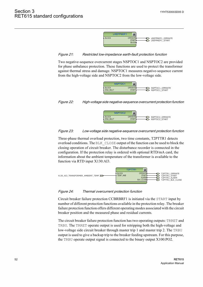
LREFPNDF1BLOCK OPERATE
STARTBLK2H
LREFPNDF1_OPERATELREFPNDF1_START
GUID-4F4027EB-496A-4D51-8F48-B05ADA7C58A1 V1 EN
Figure 21: Restricted low-impedance earth-fault protection function
Two negative-sequence overcurrent stages NSPTOC1 and NSPTOC2 are providedfor phase unbalance protection. These functions are used to protect the transformeragainst thermal stress and damage. NSPTOC1 measures negative-sequence currentfrom the high-voltage side and NSPTOC2 from the low-voltage side.
NSPTOC1BLOCKENA_MULT
OPERATESTART
NSPTOC1_OPERATENSPTOC1_START
GUID-8AD1A016-6FBF-42B7-93C9-E850A431C987 V1 EN
Figure 22: High-voltage side negative-sequence overcurrent protection function
NSPTOC2BLOCKENA_MULT
OPERATESTART
NSPTOC2_OPERATENSPTOC2_START
GUID-E081222D-DEBF-4D35-AF05-C1DFA574F6C1 V1 EN
Figure 23: Low-voltage side negative-sequence overcurrent protection function
Three-phase thermal overload protection, two time constants, T2PTTR1 detectsoverload conditions. The BLK_CLOSE output of the function can be used to block theclosing operation of circuit breaker. The disturbance recorder is connected in theconfiguration. If the protection relay is ordered with optional RTD/mA card, theinformation about the ambient temperature of the transformer is available to thefunction via RTD input X130:AI3.
T2PTTR1BLOCKTEMP_AMB
OPERATESTARTALARM
BLK_CLOSE
T2PTTR1_OPERATET2PTTR1_STARTX130_AI3_TRANSFORMER_AMBIENT_TEMPT2PTTR1_ALARMT2PTTR1_BLK_CLOSE
GUID-A31A1032-843F-4394-A10D-6F936A89CBA3 V1 EN
Figure 24: Thermal overcurrent protection function
Circuit breaker failure protection CCBRBRF1 is initiated via the START input bynumber of different protection functions available in the protection relay. The breakerfailure protection function offers different operating modes associated with the circuitbreaker position and the measured phase and residual currents.
The circuit breaker failure protection function has two operating outputs: TRRET andTRBU. The TRRET operate output is used for retripping both the high-voltage andlow-voltage side circuit breaker through master trip 1 and master trip 2. The TRBUoutput is used to give a backup trip to the breaker feeding upstream. For this purpose,the TRBU operate output signal is connected to the binary output X100:PO2.
Section 3 1YHT530003D05 DRET615 standard configurations
52 RET615Application Manual
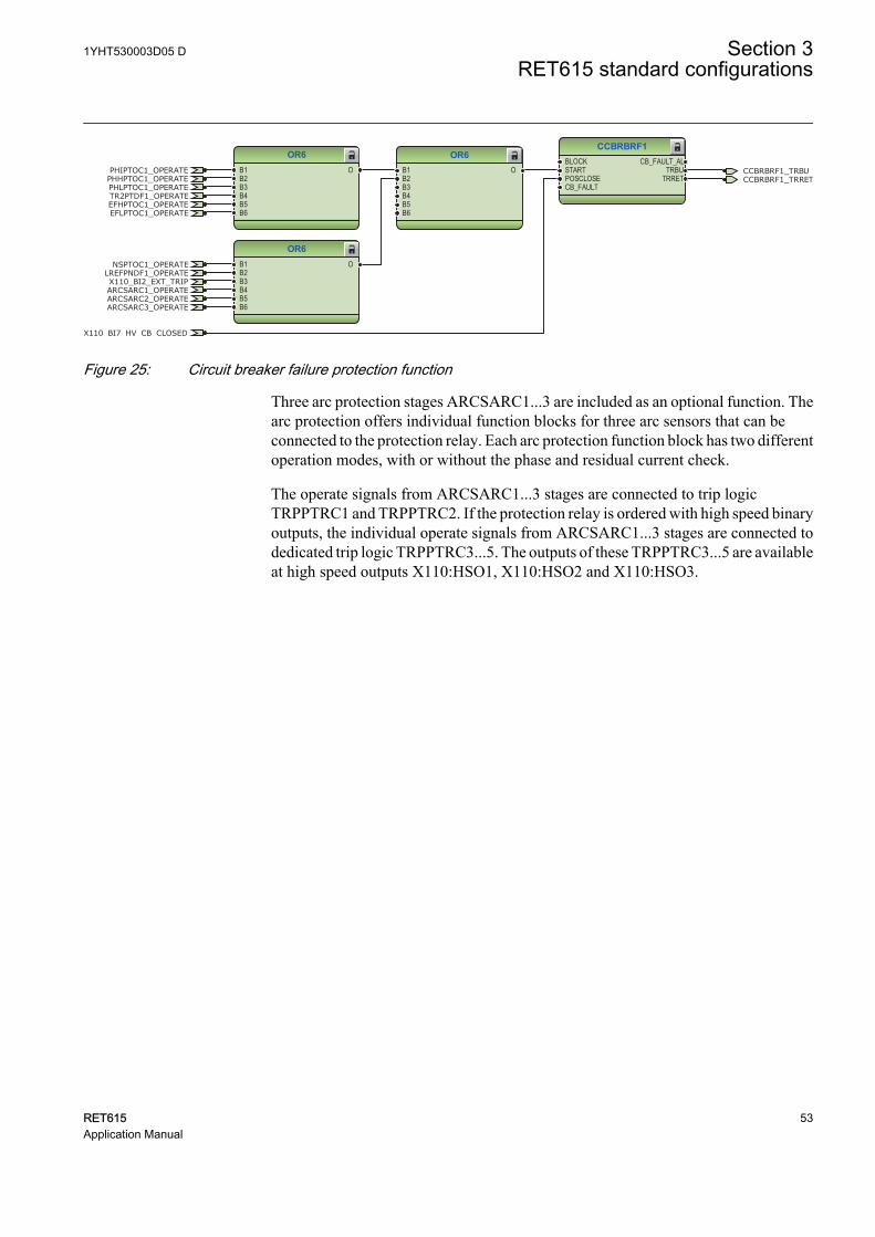
CCBRBRF1BLOCKSTARTPOSCLOSECB_FAULT
CB_FAULT_ALTRBU
TRRET
OR6B1B2B3B4B5B6
O
OR6B1B2B3B4B5B6
O
OR6B1B2B3B4B5B6
O CCBRBRF1_TRBU
X110_BI7_HV_CB_CLOSED
PHIPTOC1_OPERATE
PHLPTOC1_OPERATEPHHPTOC1_OPERATE
LREFPNDF1_OPERATE
CCBRBRF1_TRRET
NSPTOC1_OPERATE
TR2PTDF1_OPERATE
X110_BI2_EXT_TRIPARCSARC1_OPERATEARCSARC2_OPERATEARCSARC3_OPERATE
EFHPTOC1_OPERATEEFLPTOC1_OPERATE
GUID-A1E2BDD6-BE36-47E1-980C-AD9006F84AD4 V1 EN
Figure 25: Circuit breaker failure protection function
Three arc protection stages ARCSARC1...3 are included as an optional function. Thearc protection offers individual function blocks for three arc sensors that can beconnected to the protection relay. Each arc protection function block has two differentoperation modes, with or without the phase and residual current check.
The operate signals from ARCSARC1...3 stages are connected to trip logicTRPPTRC1 and TRPPTRC2. If the protection relay is ordered with high speed binaryoutputs, the individual operate signals from ARCSARC1...3 stages are connected todedicated trip logic TRPPTRC3...5. The outputs of these TRPPTRC3...5 are availableat high speed outputs X110:HSO1, X110:HSO2 and X110:HSO3.
1YHT530003D05 D Section 3RET615 standard configurations
RET615 53Application Manual
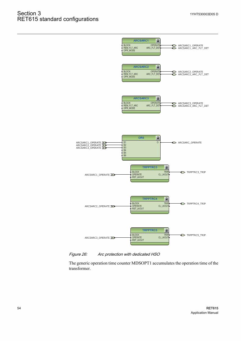
ARCSARC1BLOCKREM_FLT_ARCOPR_MODE
OPERATEARC_FLT_DET
ARCSARC2BLOCKREM_FLT_ARCOPR_MODE
OPERATEARC_FLT_DET
ARCSARC3BLOCKREM_FLT_ARCOPR_MODE
OPERATEARC_FLT_DET
OR6B1B2B3B4B5B6
O
ARCSARC1_OPERATE
ARCSARC1_OPERATE
ARCSARC2_OPERATE
ARCSARC2_OPERATE
ARCSARC3_OPERATE
ARCSARC3_OPERATE
ARCSARC1_ARC_FLT_DET
ARCSARC2_ARC_FLT_DET
ARCSARC3_ARC_FLT_DET
ARCSARC_OPERATE
GUID-274AC8EC-AA13-4B15-8AD6-7251B9AEEFDF V1 EN
TRPPTRC3BLOCKOPERATERST_LKOUT
TRIPCL_LKOUT
TRPPTRC4BLOCKOPERATERST_LKOUT
TRIPCL_LKOUT
TRPPTRC5BLOCKOPERATERST_LKOUT
TRIPCL_LKOUT
TRPPTRC3_TRIP
TRPPTRC4_TRIP
TRPPTRC5_TRIP
ARCSARC1_OPERATE
ARCSARC2_OPERATE
ARCSARC3_OPERATE
GUID-1A2D8209-8C5E-4E7D-9993-513F173E2BCD V1 EN
Figure 26: Arc protection with dedicated HSO
The generic operation time counter MDSOPT1 accumulates the operation time of thetransformer.
Section 3 1YHT530003D05 DRET615 standard configurations
54 RET615Application Manual
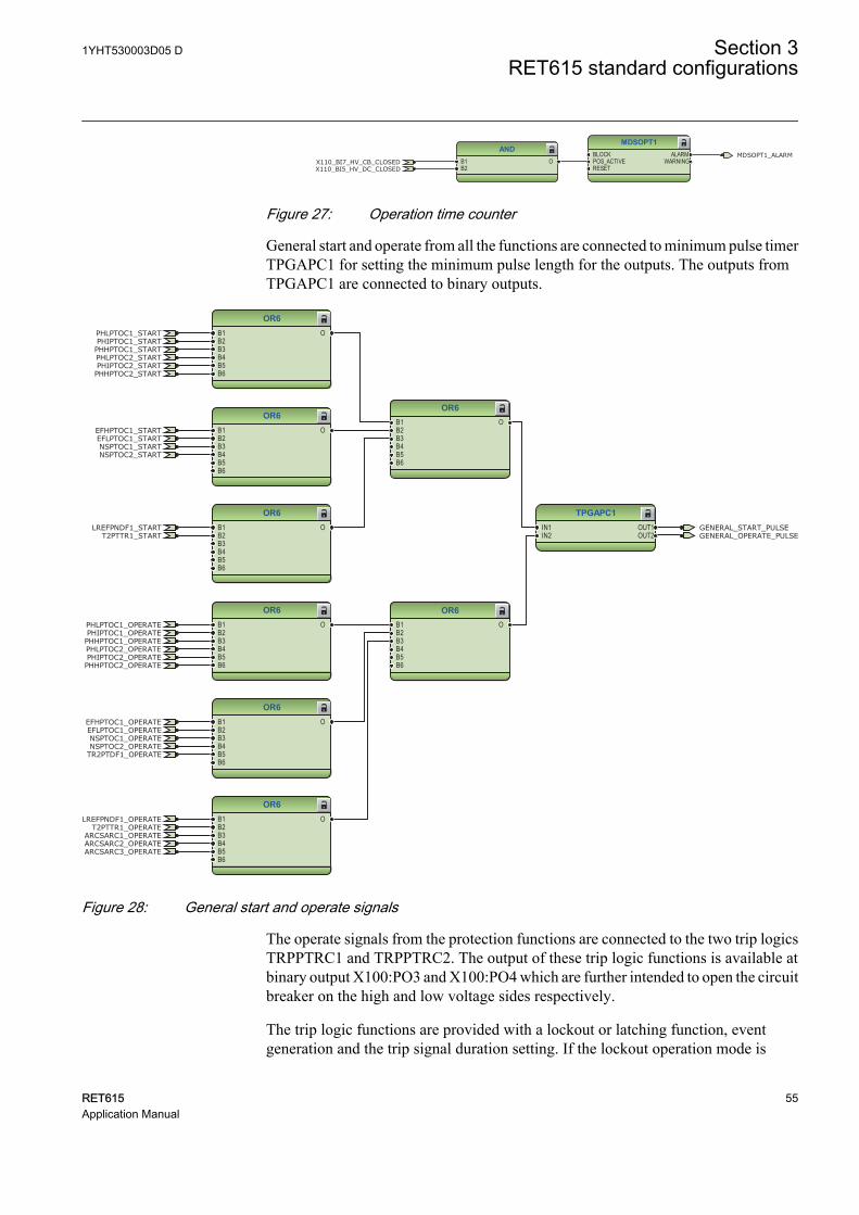
MDSOPT1BLOCKPOS_ACTIVERESET
ALARMWARNING
ANDB1B2
OX110_BI7_HV_CB_CLOSEDX110_BI5_HV_DC_CLOSED
MDSOPT1_ALARM
GUID-B118E995-1ABE-4B2D-A900-BBDC4D5F87A0 V1 EN
Figure 27: Operation time counter
General start and operate from all the functions are connected to minimum pulse timerTPGAPC1 for setting the minimum pulse length for the outputs. The outputs fromTPGAPC1 are connected to binary outputs.
OR6B1B2B3B4B5B6
O
OR6B1B2B3B4B5B6
O
OR6B1B2B3B4B5B6
O
OR6B1B2B3B4B5B6
O
OR6B1B2B3B4B5B6
O
OR6B1B2B3B4B5B6
O
OR6B1B2B3B4B5B6
O
OR6B1B2B3B4B5B6
O
TPGAPC1IN1IN2
OUT1OUT2
GENERAL_START_PULSEGENERAL_OPERATE_PULSE
PHIPTOC1_OPERATEPHLPTOC1_OPERATE
PHHPTOC1_OPERATE
LREFPNDF1_OPERATE
NSPTOC1_OPERATE
TR2PTDF1_OPERATE
ARCSARC1_OPERATEARCSARC2_OPERATEARCSARC3_OPERATE
EFHPTOC1_OPERATEEFLPTOC1_OPERATE
PHIPTOC2_OPERATEPHLPTOC2_OPERATE
PHHPTOC2_OPERATE
T2PTTR1_OPERATE
NSPTOC2_OPERATE
PHIPTOC1_STARTPHLPTOC1_START
PHHPTOC1_STARTPHLPTOC2_STARTPHIPTOC2_STARTPHHPTOC2_START
EFHPTOC1_STARTEFLPTOC1_STARTNSPTOC1_STARTNSPTOC2_START
LREFPNDF1_STARTT2PTTR1_START
GUID-38D6C616-DA6F-49B4-A617-AF6A900036B1 V1 EN
Figure 28: General start and operate signals
The operate signals from the protection functions are connected to the two trip logicsTRPPTRC1 and TRPPTRC2. The output of these trip logic functions is available atbinary output X100:PO3 and X100:PO4 which are further intended to open the circuitbreaker on the high and low voltage sides respectively.
The trip logic functions are provided with a lockout or latching function, eventgeneration and the trip signal duration setting. If the lockout operation mode is
1YHT530003D05 D Section 3RET615 standard configurations
RET615 55Application Manual
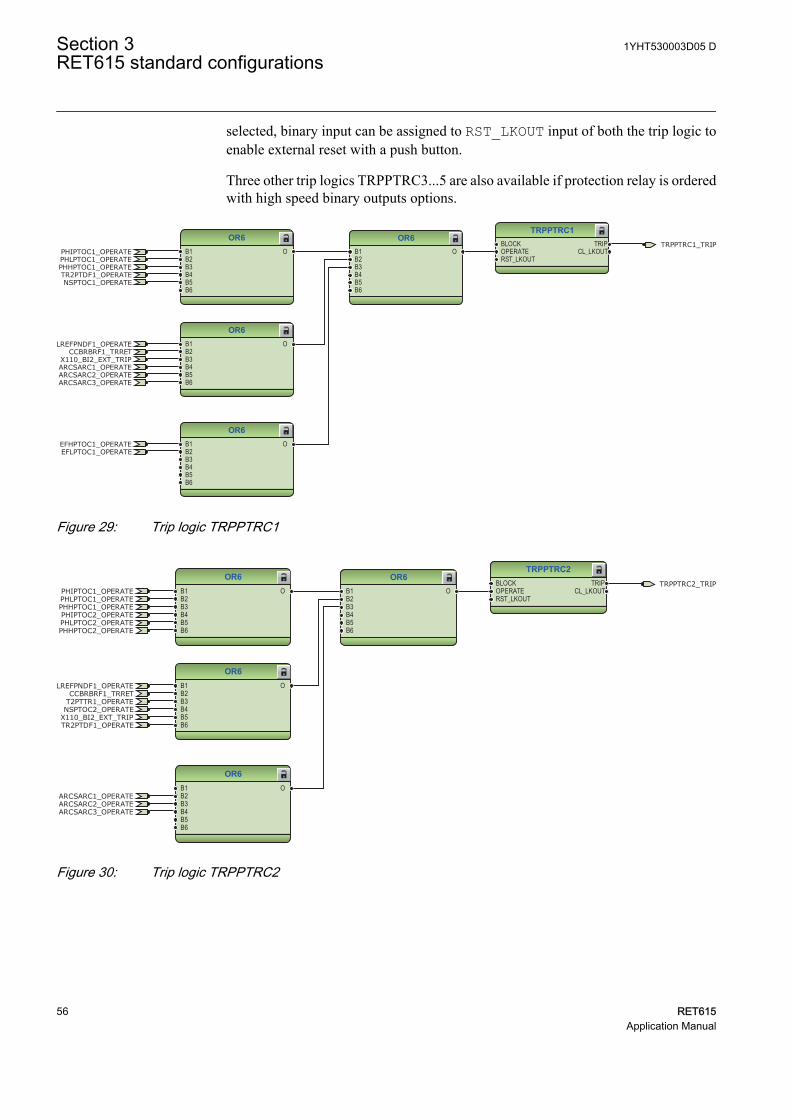
selected, binary input can be assigned to RST_LKOUT input of both the trip logic toenable external reset with a push button.
Three other trip logics TRPPTRC3...5 are also available if protection relay is orderedwith high speed binary outputs options.
TRPPTRC1BLOCKOPERATERST_LKOUT
TRIPCL_LKOUT
OR6B1B2B3B4B5B6
O
OR6B1B2B3B4B5B6
O
OR6B1B2B3B4B5B6
O
OR6B1B2B3B4B5B6
OTRPPTRC1_TRIP
PHIPTOC1_OPERATEPHLPTOC1_OPERATEPHHPTOC1_OPERATE
LREFPNDF1_OPERATECCBRBRF1_TRRET
NSPTOC1_OPERATETR2PTDF1_OPERATE
X110_BI2_EXT_TRIPARCSARC1_OPERATEARCSARC2_OPERATEARCSARC3_OPERATE
EFHPTOC1_OPERATEEFLPTOC1_OPERATE
GUID-1F990D2C-FE15-4812-A310-25AE81F77B79 V1 EN
Figure 29: Trip logic TRPPTRC1
OR6B1B2B3B4B5B6
O
OR6B1B2B3B4B5B6
O
OR6B1B2B3B4B5B6
O
OR6B1B2B3B4B5B6
O
TRPPTRC2BLOCKOPERATERST_LKOUT
TRIPCL_LKOUT
TRPPTRC2_TRIPPHIPTOC1_OPERATEPHLPTOC1_OPERATEPHHPTOC1_OPERATE
LREFPNDF1_OPERATECCBRBRF1_TRRET
TR2PTDF1_OPERATEX110_BI2_EXT_TRIP
ARCSARC1_OPERATEARCSARC2_OPERATEARCSARC3_OPERATE
PHIPTOC2_OPERATEPHLPTOC2_OPERATEPHHPTOC2_OPERATE
T2PTTR1_OPERATENSPTOC2_OPERATE
GUID-0A30841B-0006-4BEA-8D56-18684539E86E V1 EN
Figure 30: Trip logic TRPPTRC2
Section 3 1YHT530003D05 DRET615 standard configurations
56 RET615Application Manual
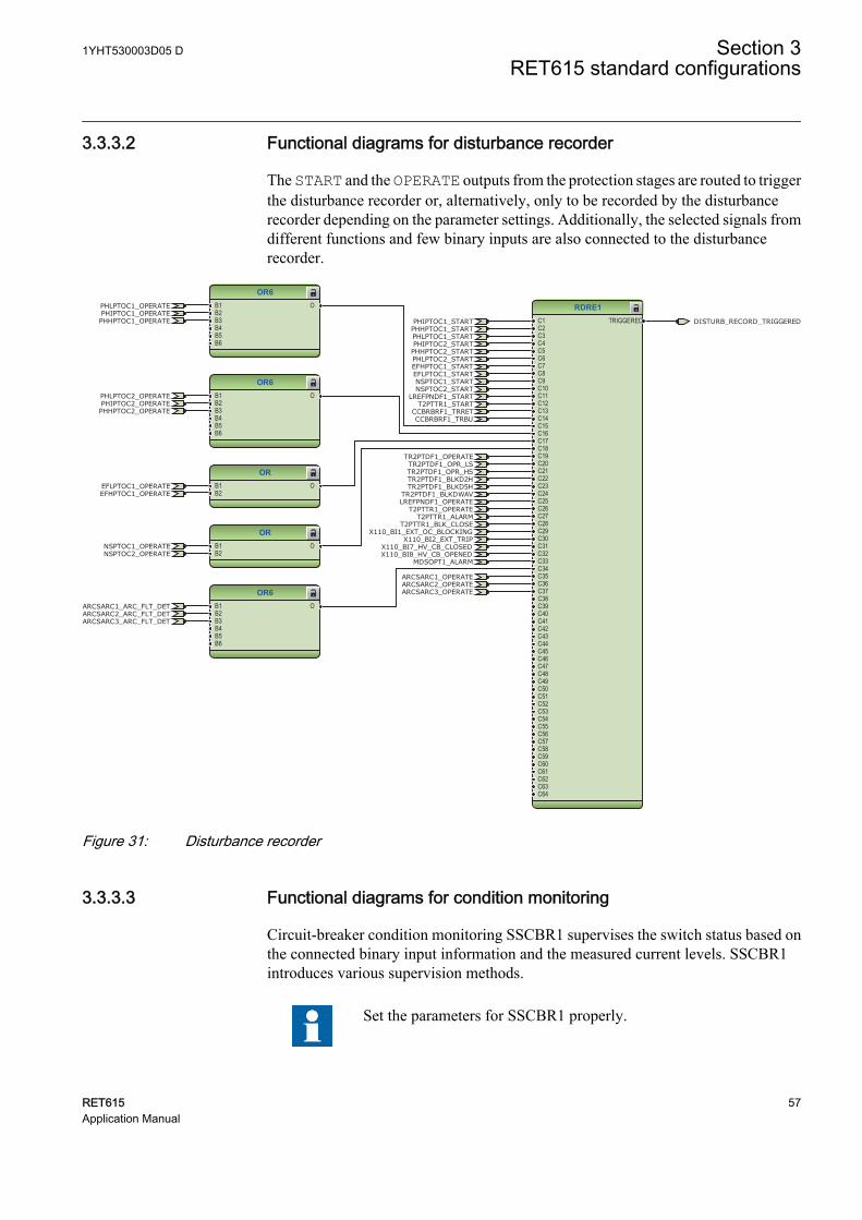
3.3.3.2 Functional diagrams for disturbance recorder
The START and the OPERATE outputs from the protection stages are routed to triggerthe disturbance recorder or, alternatively, only to be recorded by the disturbancerecorder depending on the parameter settings. Additionally, the selected signals fromdifferent functions and few binary inputs are also connected to the disturbancerecorder.
RDRE1C1C2C3C4C5C6C7C8C9C10C11C12C13C14C15C16C17C18C19C20C21C22C23C24C25C26C27C28C29C30C31C32C33C34C35C36C37C38C39C40C41C42C43C44C45C46C47C48C49C50C51C52C53C54C55C56C57C58C59C60C61C62C63C64
TRIGGERED
OR6B1B2B3B4B5B6
O
ORB1B2
O
ORB1B2
O
OR6B1B2B3B4B5B6
O
OR6B1B2B3B4B5B6
O
CCBRBRF1_TRBU
X110_BI8_HV_CB_OPENEDX110_BI7_HV_CB_CLOSED
PHIPTOC1_OPERATEPHLPTOC1_OPERATE
PHHPTOC1_OPERATE
LREFPNDF1_OPERATE
CCBRBRF1_TRRET
NSPTOC1_OPERATE
TR2PTDF1_OPERATE
X110_BI2_EXT_TRIP
ARCSARC1_OPERATEARCSARC2_OPERATEARCSARC3_OPERATE
EFHPTOC1_OPERATEEFLPTOC1_OPERATE
PHIPTOC2_OPERATEPHLPTOC2_OPERATE
PHHPTOC2_OPERATE
T2PTTR1_OPERATE
NSPTOC2_OPERATE
PHIPTOC1_START
PHLPTOC1_STARTPHHPTOC1_START
PHLPTOC2_START
PHIPTOC2_STARTPHHPTOC2_START
EFHPTOC1_STARTEFLPTOC1_STARTNSPTOC1_STARTNSPTOC2_START
LREFPNDF1_STARTT2PTTR1_START
X110_BI1_EXT_OC_BLOCKING
ARCSARC1_ARC_FLT_DETARCSARC2_ARC_FLT_DETARCSARC3_ARC_FLT_DET
TR2PTDF1_OPR_LSTR2PTDF1_OPR_HSTR2PTDF1_BLKD2HTR2PTDF1_BLKD5H
TR2PTDF1_BLKDWAV
T2PTTR1_ALARMT2PTTR1_BLK_CLOSE
MDSOPT1_ALARM
DISTURB_RECORD_TRIGGERED
GUID-B0579631-2E87-4837-8DFF-3A185F324715 V1 EN
Figure 31: Disturbance recorder
3.3.3.3 Functional diagrams for condition monitoring
Circuit-breaker condition monitoring SSCBR1 supervises the switch status based onthe connected binary input information and the measured current levels. SSCBR1introduces various supervision methods.
Set the parameters for SSCBR1 properly.
1YHT530003D05 D Section 3RET615 standard configurations
RET615 57Application Manual
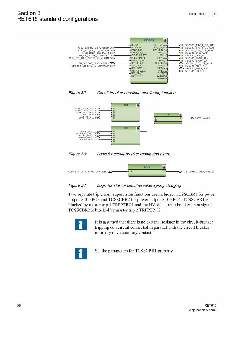
SSCBR1BLOCKPOSOPENPOSCLOSEOPEN_CB_EXECLOSE_CB_EXEPRES_ALM_INPRES_LO_INSPR_CHR_STSPR_CHRRST_IPOWRST_CB_WEARRST_TRV_TRST_SPR_T
TRV_T_OP_ALMTRV_T_CL_ALMSPR_CHR_ALM
OPR_ALMOPR_LO
IPOW_ALMIPOW_LO
CB_LIFE_ALMMON_ALM
PRES_ALMPRES_LO
OPENPOSINVALIDPOSCLOSEPOS
HV_CB_CLOSE_COMMANDHV_CB_OPEN_COMMAND
X110_BI8_HV_CB_OPENEDX110_BI7_HV_CB_CLOSED
X110_BI3_GAS_PRESSURE_ALARM
X110_BI4_CB_SPRING_CHARGEDCB_SPRING_DISCHARGED
SSCBR1_TRV_T_OP_ALMSSCBR1_TRV_T_CL_ALMSSCBR1_SPR_CHR_ALMSSCBR1_OPR_ALMSSCBR1_OPR_LOSSCBR1_IPOW_ALMSSCBR1_IPOW_LOSSCBR1_CB_LIFE_ALMSSCBR1_MON_ALMSSCBR1_PRES_ALMSSCBR1_PRES_LO
GUID-ED1DAFD1-25DE-4030-B97C-80466F72A12A V1 EN
Figure 32: Circuit breaker condition monitoring function
OR6B1B2B3B4B5B6
O
OR6B1B2B3B4B5B6
O
ORB1B2
O
SSCBR1_TRV_T_OP_ALMSSCBR1_TRV_T_CL_ALMSSCBR1_SPR_CHR_ALM
SSCBR1_OPR_ALMSSCBR1_OPR_LO
SSCBR1_IPOW_ALM
SSCBR1_IPOW_LOSSCBR1_CB_LIFE_ALM
SSCBR1_MON_ALMSSCBR1_PRES_ALM
SSCBR1_PRES_LO
SSCBR1_ALARMS
GUID-BC74A739-D6AE-491B-B9C7-88879FB38645 V1 EN
Figure 33: Logic for circuit-breaker monitoring alarm
NOTIN OUTX110_BI4_CB_SPRING_CHARGED CB_SPRING_DISCHARGED
GUID-0F1FA253-DFB0-4AC3-AC15-89F112E74B9C V1 EN
Figure 34: Logic for start of circuit-breaker spring charging
Two separate trip circuit supervision functions are included, TCSSCBR1 for poweroutput X100:PO3 and TCSSCBR2 for power output X100:PO4. TCSSCBR1 isblocked by master trip 1 TRPPTRC1 and the HV side circuit breaker open signal.TCSSCBR2 is blocked by master trip 2 TRPPTRC2.
It is assumed that there is no external resistor in the circuit-breakertripping coil circuit connected in parallel with the circuit breakernormally open auxiliary contact.
Set the parameters for TCSSCBR1 properly.
Section 3 1YHT530003D05 DRET615 standard configurations
58 RET615Application Manual
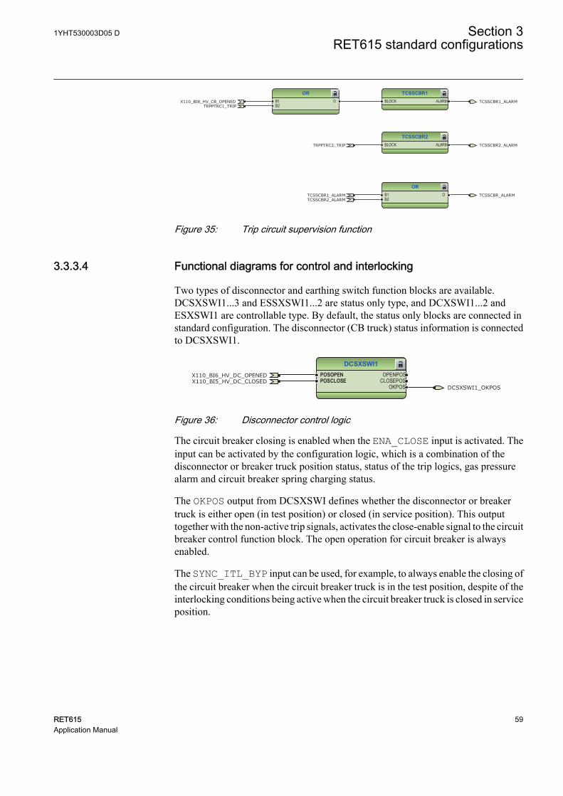
ORB1B2
OTCSSCBR1_ALARMTCSSCBR2_ALARM
TCSSCBR_ALARM
TCSSCBR1BLOCK ALARM
ORB1B2
OTRPPTRC1_TRIP
X110_BI8_HV_CB_OPENED TCSSCBR1_ALARM
TCSSCBR2BLOCK ALARMTRPPTRC2_TRIP TCSSCBR2_ALARM
GUID-DDD3F2C5-C538-4744-9C95-005D105AE8BB V1 EN
Figure 35: Trip circuit supervision function
3.3.3.4 Functional diagrams for control and interlocking
Two types of disconnector and earthing switch function blocks are available.DCSXSWI1...3 and ESSXSWI1...2 are status only type, and DCXSWI1...2 andESXSWI1 are controllable type. By default, the status only blocks are connected instandard configuration. The disconnector (CB truck) status information is connectedto DCSXSWI1.
DCSXSWI1POSOPENPOSCLOSE
OPENPOSCLOSEPOS
OKPOS DCSXSWI1_OKPOS
X110_BI6_HV_DC_OPENEDX110_BI5_HV_DC_CLOSED
GUID-B155EF68-F1F3-4E28-BC94-188985DA0977 V1 EN
Figure 36: Disconnector control logic
The circuit breaker closing is enabled when the ENA_CLOSE input is activated. Theinput can be activated by the configuration logic, which is a combination of thedisconnector or breaker truck position status, status of the trip logics, gas pressurealarm and circuit breaker spring charging status.
The OKPOS output from DCSXSWI defines whether the disconnector or breakertruck is either open (in test position) or closed (in service position). This outputtogether with the non-active trip signals, activates the close-enable signal to the circuitbreaker control function block. The open operation for circuit breaker is alwaysenabled.
The SYNC_ITL_BYP input can be used, for example, to always enable the closing ofthe circuit breaker when the circuit breaker truck is in the test position, despite of theinterlocking conditions being active when the circuit breaker truck is closed in serviceposition.
1YHT530003D05 D Section 3RET615 standard configurations
RET615 59Application Manual
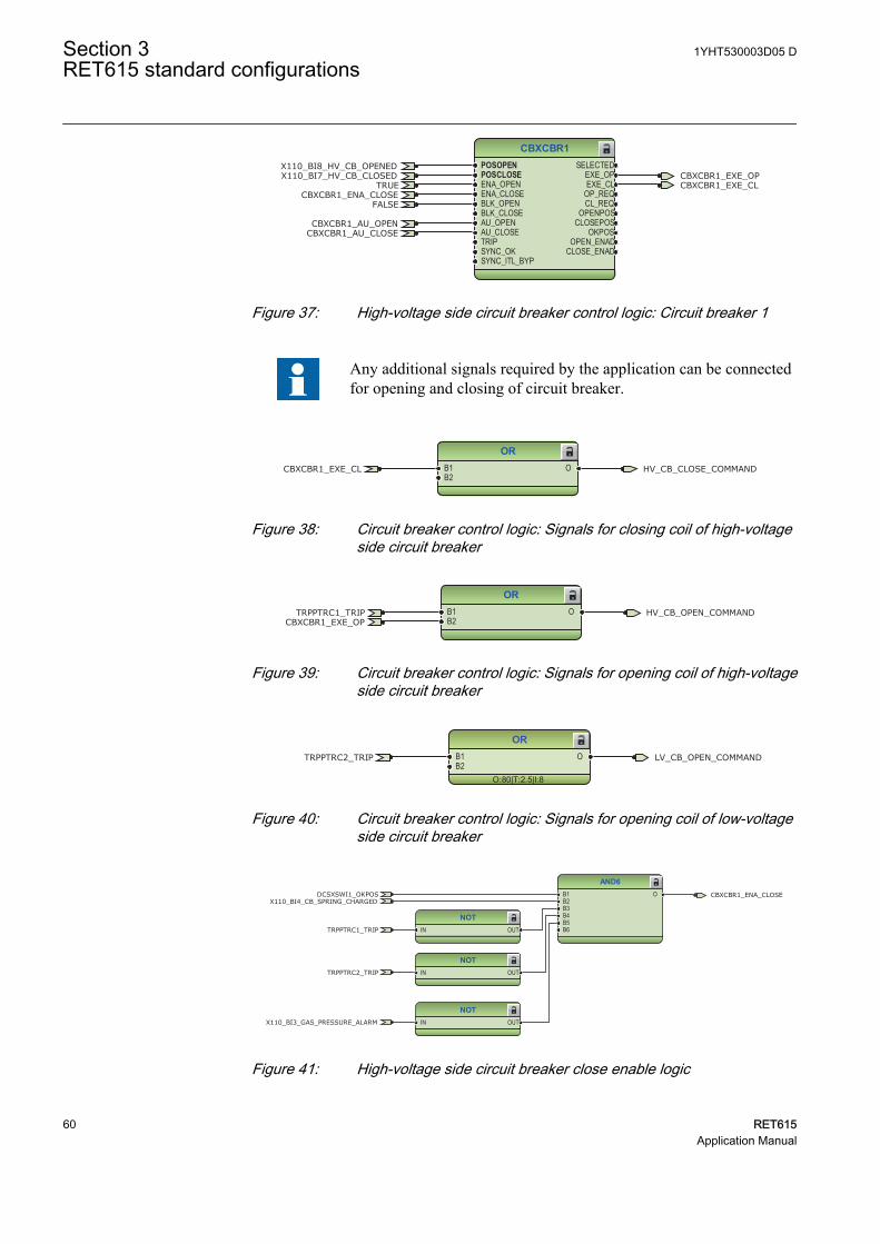
CBXCBR1POSOPENPOSCLOSEENA_OPENENA_CLOSEBLK_OPENBLK_CLOSEAU_OPENAU_CLOSETRIPSYNC_OKSYNC_ITL_BYP
SELECTEDEXE_OPEXE_CL
OP_REQCL_REQ
OPENPOSCLOSEPOS
OKPOSOPEN_ENAD
CLOSE_ENAD
TRUECBXCBR1_ENA_CLOSE
CBXCBR1_EXE_OPCBXCBR1_EXE_CL
X110_BI8_HV_CB_OPENEDX110_BI7_HV_CB_CLOSED
FALSE
CBXCBR1_AU_OPENCBXCBR1_AU_CLOSE
GUID-6573B80C-5EE1-4C0C-90E5-B5A16B43DF5E V2 EN
Figure 37: High-voltage side circuit breaker control logic: Circuit breaker 1
Any additional signals required by the application can be connectedfor opening and closing of circuit breaker.
ORB1B2
O HV_CB_CLOSE_COMMANDCBXCBR1_EXE_CL
GUID-0338F99F-CB36-4E4F-AB7F-BD4459585C48 V1 EN
Figure 38: Circuit breaker control logic: Signals for closing coil of high-voltageside circuit breaker
ORB1B2
O HV_CB_OPEN_COMMANDTRPPTRC1_TRIPCBXCBR1_EXE_OP
GUID-473459E2-2200-49E1-8D7D-E71593230544 V1 EN
Figure 39: Circuit breaker control logic: Signals for opening coil of high-voltageside circuit breaker
OR
O:80|T:2.5|I:8
B1B2
O LV_CB_OPEN_COMMANDTRPPTRC2_TRIP
GUID-B19FA4A1-B690-40F7-A8BF-8E1A60634FE6 V1 EN
Figure 40: Circuit breaker control logic: Signals for opening coil of low-voltageside circuit breaker
NOTIN OUT
AND6B1B2B3B4B5B6
O
NOTIN OUT
NOTIN OUT
TRPPTRC1_TRIP
CBXCBR1_ENA_CLOSE
X110_BI3_GAS_PRESSURE_ALARM
TRPPTRC2_TRIP
DCSXSWI1_OKPOSX110_BI4_CB_SPRING_CHARGED
GUID-5FBEB9B6-EC84-49F3-9742-975F7FB50FED V1 EN
Figure 41: High-voltage side circuit breaker close enable logic
Section 3 1YHT530003D05 DRET615 standard configurations
60 RET615Application Manual
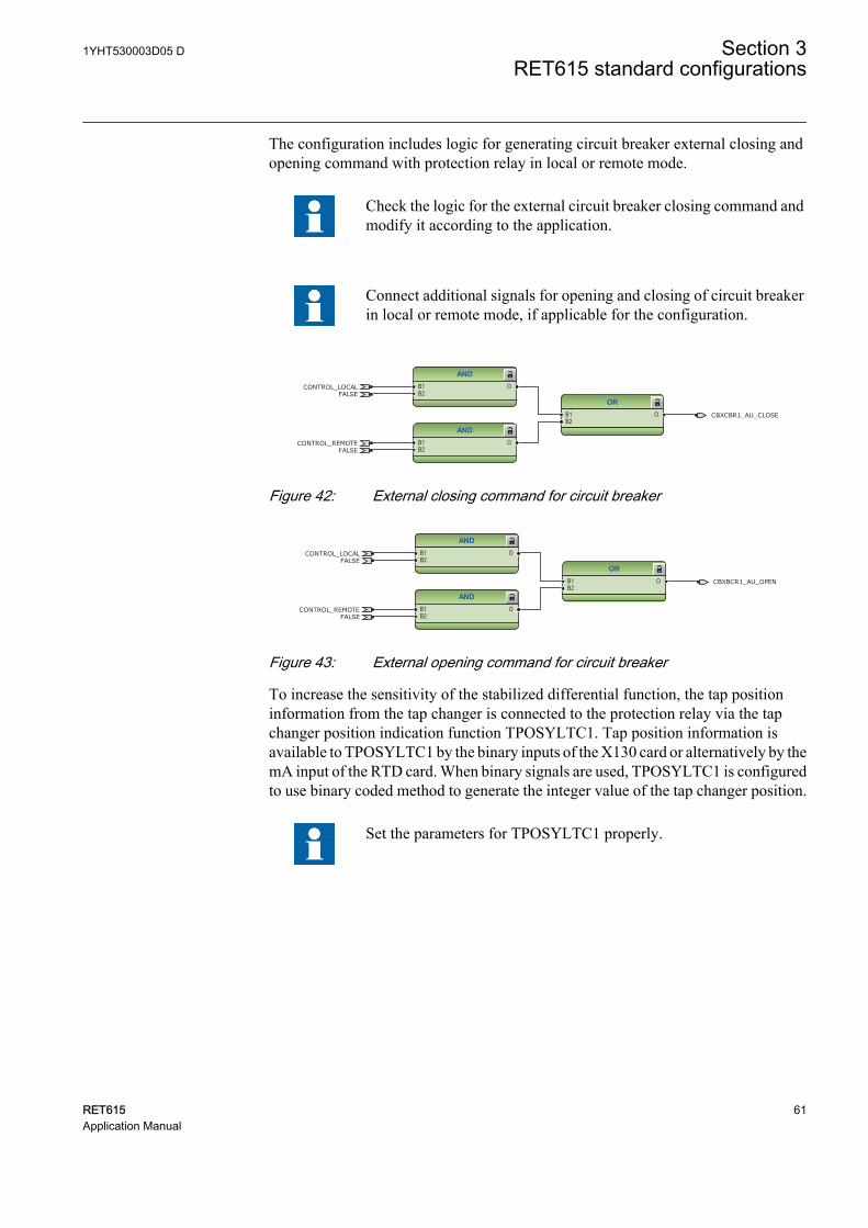
The configuration includes logic for generating circuit breaker external closing andopening command with protection relay in local or remote mode.
Check the logic for the external circuit breaker closing command andmodify it according to the application.
Connect additional signals for opening and closing of circuit breakerin local or remote mode, if applicable for the configuration.
ANDB1B2
O
ANDB1B2
O
ORB1B2
O CBXCBR1_AU_CLOSE
CONTROL_LOCAL
CONTROL_REMOTE
FALSE
FALSE
GUID-B752AF2C-5D65-43EE-ACB0-1462917688AC V1 EN
Figure 42: External closing command for circuit breaker
ANDB1B2
O
ORB1B2
O
ANDB1B2
O
CBXBCR1_AU_OPEN
CONTROL_LOCAL
CONTROL_REMOTE
FALSE
FALSE
GUID-E710539F-4F9E-4057-B7F8-55A55AC16843 V1 EN
Figure 43: External opening command for circuit breaker
To increase the sensitivity of the stabilized differential function, the tap positioninformation from the tap changer is connected to the protection relay via the tapchanger position indication function TPOSYLTC1. Tap position information isavailable to TPOSYLTC1 by the binary inputs of the X130 card or alternatively by themA input of the RTD card. When binary signals are used, TPOSYLTC1 is configuredto use binary coded method to generate the integer value of the tap changer position.
Set the parameters for TPOSYLTC1 properly.
1YHT530003D05 D Section 3RET615 standard configurations
RET615 61Application Manual
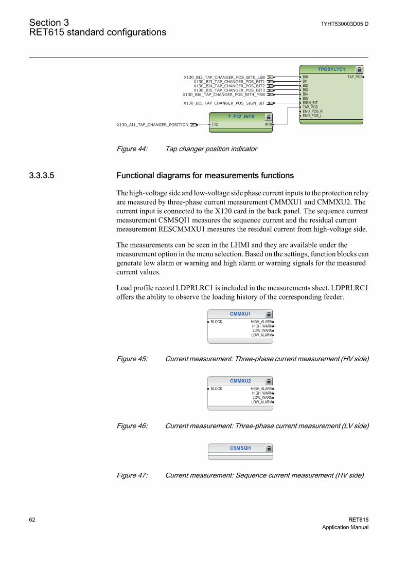
TPOSYLTC1BI0BI1BI2BI3BI4BI5SIGN_BITTAP_POSEND_POS_REND_POS_L
TAP_POS
T_F32_INT8F32 INT8
X130_BI2_TAP_CHANGER_POS_BIT0_LSBX130_BI3_TAP_CHANGER_POS_BIT1X130_BI4_TAP_CHANGER_POS_BIT2X130_BI5_TAP_CHANGER_POS_BIT3
X130_BI6_TAP_CHANGER_POS_BIT4_MSB
X130_BI1_TAP_CHANGER_POS_SIGN_BIT
X130_AI1_TAP_CHANGER_POSITION
GUID-46849CBC-A321-4CB8-B2F2-8766A27984D9 V2 EN
Figure 44: Tap changer position indicator
3.3.3.5 Functional diagrams for measurements functions
The high-voltage side and low-voltage side phase current inputs to the protection relayare measured by three-phase current measurement CMMXU1 and CMMXU2. Thecurrent input is connected to the X120 card in the back panel. The sequence currentmeasurement CSMSQI1 measures the sequence current and the residual currentmeasurement RESCMMXU1 measures the residual current from high-voltage side.
The measurements can be seen in the LHMI and they are available under themeasurement option in the menu selection. Based on the settings, function blocks cangenerate low alarm or warning and high alarm or warning signals for the measuredcurrent values.
Load profile record LDPRLRC1 is included in the measurements sheet. LDPRLRC1offers the ability to observe the loading history of the corresponding feeder.
CMMXU1BLOCK HIGH_ALARM
HIGH_WARNLOW_WARN
LOW_ALARM
GUID-DF7A208C-79C2-42A2-9E10-73292AF64F5F V1 EN
Figure 45: Current measurement: Three-phase current measurement (HV side)
CMMXU2BLOCK HIGH_ALARM
HIGH_WARNLOW_WARN
LOW_ALARM
GUID-09BA7F55-66BC-4BCE-AE6D-0385F62AFD98 V1 EN
Figure 46: Current measurement: Three-phase current measurement (LV side)
CSMSQI1
GUID-87C938E0-4BBE-44A5-A92D-90DB026DAC28 V1 EN
Figure 47: Current measurement: Sequence current measurement (HV side)
Section 3 1YHT530003D05 DRET615 standard configurations
62 RET615Application Manual
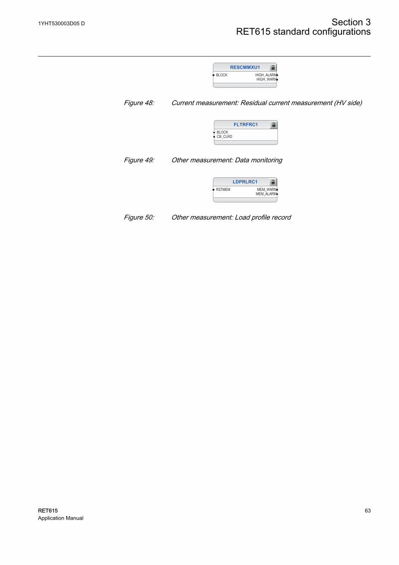
RESCMMXU1BLOCK HIGH_ALARM
HIGH_WARN
GUID-0A5DDB16-07DC-4BB2-9DEE-9C4870D6DD8E V1 EN
Figure 48: Current measurement: Residual current measurement (HV side)
FLTRFRC1BLOCKCB_CLRD
GUID-5F074F06-2BE7-4369-9B70-FC6928CC2558 V2 EN
Figure 49: Other measurement: Data monitoring
LDPRLRC1RSTMEM MEM_WARN
MEM_ALARM
GUID-FA188530-269F-45B2-975B-690B4899338C V2 EN
Figure 50: Other measurement: Load profile record
1YHT530003D05 D Section 3RET615 standard configurations
RET615 63Application Manual
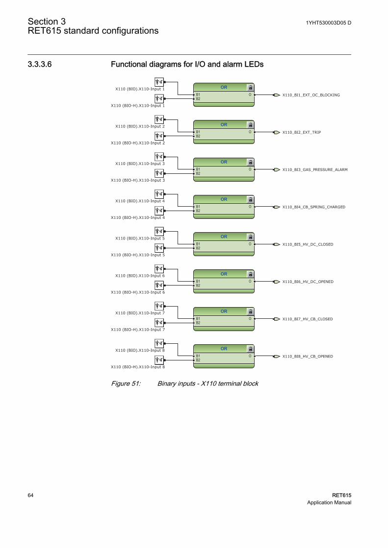
3.3.3.6 Functional diagrams for I/O and alarm LEDs
ORB1B2
O
ORB1B2
O
ORB1B2
O
ORB1B2
O
ORB1B2
O
ORB1B2
O
ORB1B2
O
ORB1B2
O X110_BI8_HV_CB_OPENED
X110_BI7_HV_CB_CLOSED
X110_BI3_GAS_PRESSURE_ALARM
X110_BI4_CB_SPRING_CHARGED
X110_BI6_HV_DC_OPENED
X110_BI5_HV_DC_CLOSED
X110_BI2_EXT_TRIP
X110_BI1_EXT_OC_BLOCKINGX110 (BIO).X110-Input 1
X110 (BIO).X110-Input 3
X110 (BIO-H).X110-Input 8
X110 (BIO-H).X110-Input 1
X110 (BIO-H).X110-Input 6
X110 (BIO).X110-Input 7
X110 (BIO).X110-Input 4
X110 (BIO).X110-Input 6
X110 (BIO-H).X110-Input 2
X110 (BIO-H).X110-Input 3
X110 (BIO-H).X110-Input 4
X110 (BIO).X110-Input 8
X110 (BIO-H).X110-Input 7
X110 (BIO).X110-Input 2
X110 (BIO-H).X110-Input 5
X110 (BIO).X110-Input 5
GUID-C8940C83-4238-482C-A189-B456DC3669DE V1 EN
Figure 51: Binary inputs - X110 terminal block
Section 3 1YHT530003D05 DRET615 standard configurations
64 RET615Application Manual
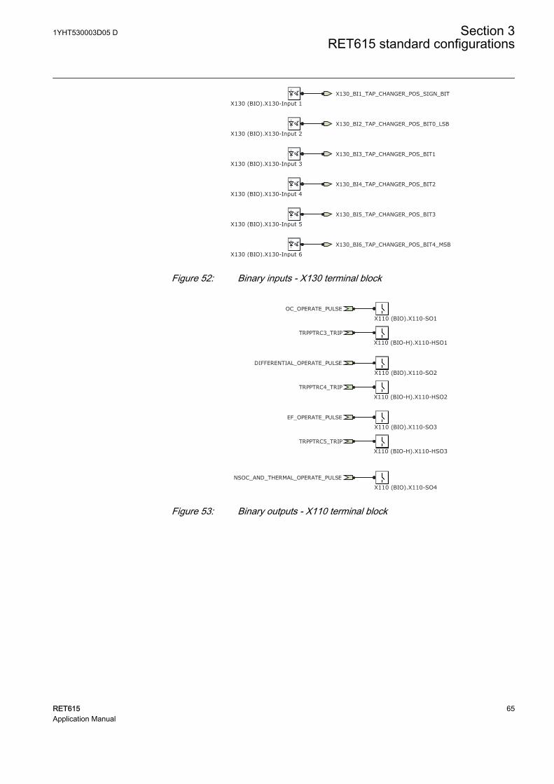
X130_BI2_TAP_CHANGER_POS_BIT0_LSB
X130_BI3_TAP_CHANGER_POS_BIT1
X130_BI4_TAP_CHANGER_POS_BIT2
X130_BI5_TAP_CHANGER_POS_BIT3
X130_BI6_TAP_CHANGER_POS_BIT4_MSB
X130_BI1_TAP_CHANGER_POS_SIGN_BIT
X130 (BIO).X130-Input 1
X130 (BIO).X130-Input 2
X130 (BIO).X130-Input 3
X130 (BIO).X130-Input 4
X130 (BIO).X130-Input 5
X130 (BIO).X130-Input 6GUID-85CA568C-28BE-4C74-B658-EE686EE97FD0 V1 EN
Figure 52: Binary inputs - X130 terminal block
OC_OPERATE_PULSE
DIFFERENTIAL_OPERATE_PULSE
EF_OPERATE_PULSE
NSOC_AND_THERMAL_OPERATE_PULSE
TRPPTRC3_TRIP
TRPPTRC4_TRIP
TRPPTRC5_TRIP
X110 (BIO).X110-SO1
X110 (BIO).X110-SO2
X110 (BIO).X110-SO4
X110 (BIO).X110-SO3
X110 (BIO-H).X110-HSO1
X110 (BIO-H).X110-HSO2
X110 (BIO-H).X110-HSO3
GUID-6316002C-CEA5-4C4C-AC69-C372086E066B V1 EN
Figure 53: Binary outputs - X110 terminal block
1YHT530003D05 D Section 3RET615 standard configurations
RET615 65Application Manual
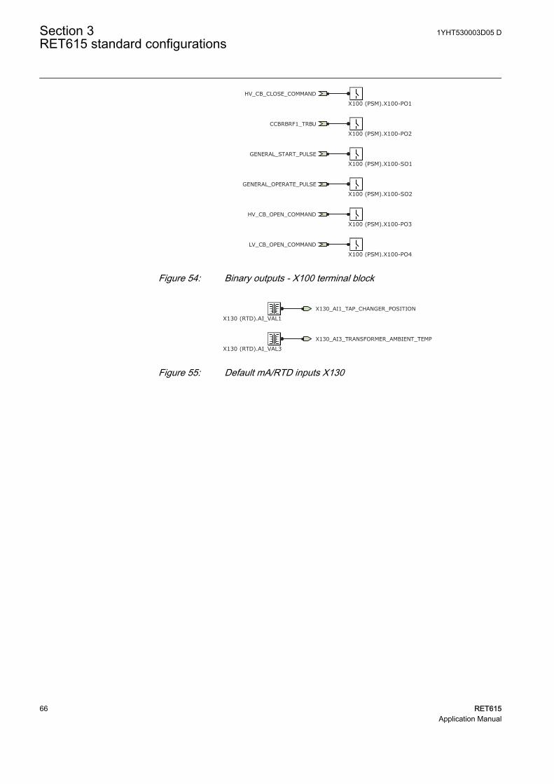
HV_CB_CLOSE_COMMAND
HV_CB_OPEN_COMMAND
GENERAL_START_PULSE
GENERAL_OPERATE_PULSE
LV_CB_OPEN_COMMAND
CCBRBRF1_TRBU
X100 (PSM).X100-PO1
X100 (PSM).X100-PO2
X100 (PSM).X100-SO1
X100 (PSM).X100-SO2
X100 (PSM).X100-PO3
X100 (PSM).X100-PO4GUID-DF057874-938C-47B6-B880-64C72DDDBD0A V1 EN
Figure 54: Binary outputs - X100 terminal block
X130_AI1_TAP_CHANGER_POSITION
X130 (RTD).AI_VAL1
X130_AI3_TRANSFORMER_AMBIENT_TEMP
X130 (RTD).AI_VAL3GUID-7A1D2A2C-1CAE-473B-91E0-C6F3CF990B68 V1 EN
Figure 55: Default mA/RTD inputs X130
Section 3 1YHT530003D05 DRET615 standard configurations
66 RET615Application Manual
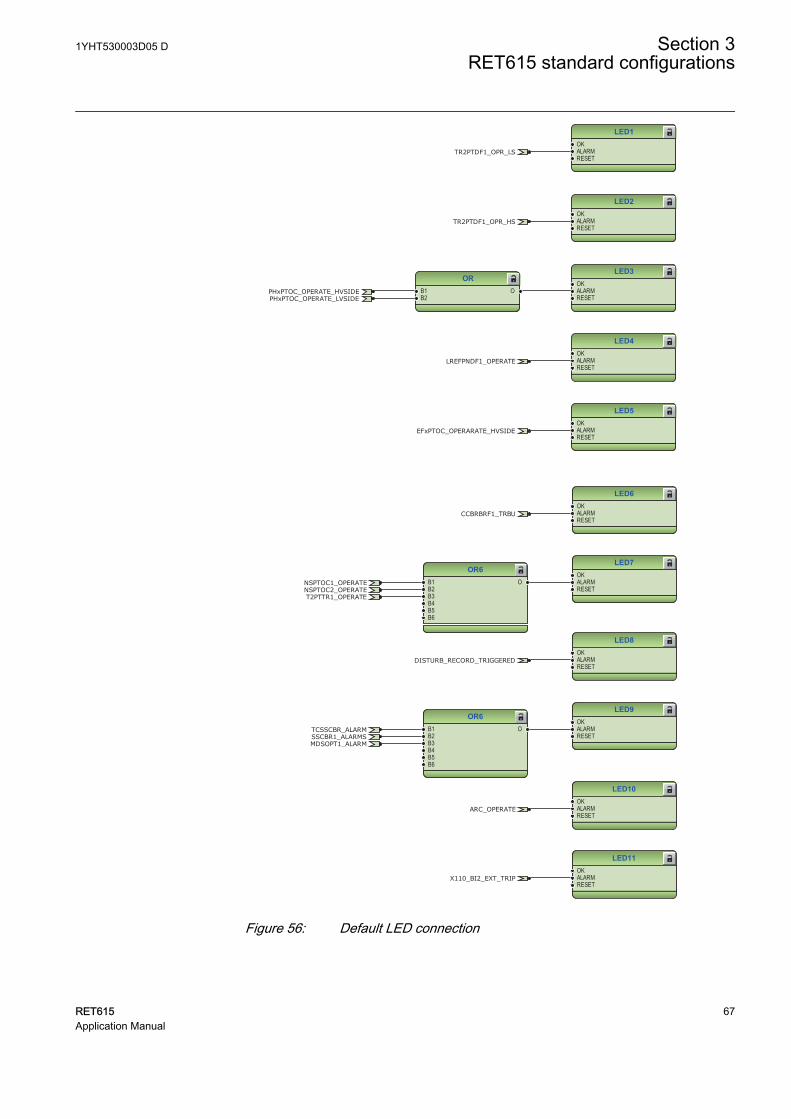
LED1OKALARMRESET
LED2OKALARMRESET
LED3OKALARMRESET
LED4OKALARMRESET
LED5OKALARMRESET
ORB1B2
O
LREFPNDF1_OPERATE
PHxPTOC_OPERATE_HVSIDEPHxPTOC_OPERATE_LVSIDE
EFxPTOC_OPERARATE_HVSIDE
TR2PTDF1_OPR_LS
TR2PTDF1_OPR_HS
GUID-8F90BE2C-3DDA-4C29-9C12-CC78FBEDA8C0 V1 EN
LED6OKALARMRESET
LED7OKALARMRESET
LED8OKALARMRESET
LED9OKALARMRESET
LED10OKALARMRESET
LED11OKALARMRESET
OR6B1B2B3B4B5B6
O
OR6B1B2B3B4B5B6
O
CCBRBRF1_TRBU
NSPTOC1_OPERATE
X110_BI2_EXT_TRIP
T2PTTR1_OPERATENSPTOC2_OPERATE
MDSOPT1_ALARM
ARC_OPERATE
TCSSCBR_ALARMSSCBR1_ALARMS
DISTURB_RECORD_TRIGGERED
GUID-7767A8BC-CE53-4BD2-B7C3-3AE6A301105B V1 EN
Figure 56: Default LED connection
1YHT530003D05 D Section 3RET615 standard configurations
RET615 67Application Manual
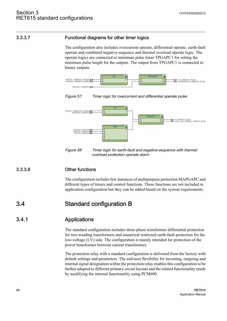
3.3.3.7 Functional diagrams for other timer logics
The configuration also includes overcurrent operate, differential operate, earth-faultoperate and combined negative-sequence and thermal overload operate logic. Theoperate logics are connected to minimum pulse timer TPGAPC1 for setting theminimum pulse length for the outputs. The output from TPGAPC1 is connected tobinary outputs.
TPGAPC2IN1IN2
OUT1OUT2
ORB1B2
O OC_OPERATE_PULSEDIFFERENTIAL_OPERATE_PULSE
TR2PTDF1_OPERATE
PHxPTOC_OPERATE_HVSIDEPHxPTOC_OPERATE_LVSIDE
GUID-413A994B-7246-4A21-8464-8BBC00DA9C9B V1 EN
Figure 57: Timer logic for overcurrent and differential operate pulse
TPGAPC3IN1IN2
OUT1OUT2
OR6B1B2B3B4B5B6
O
ORB1B2
O
EF_OPERATE_PULSENSOC_AND_THERMAL_OPERATE_PULSE
LREFPNDF1_OPERATE
NSPTOC1_OPERATE
T2PTTR1_OPERATENSPTOC2_OPERATE
EFxPTOC_OPERARATE_HVSIDE
GUID-582C011E-36AD-4FBD-AD67-E3B10A39B3BF V1 EN
Figure 58: Timer logic for earth-fault and negative-sequence with thermaloverload protection operate alarm
3.3.3.8 Other functions
The configuration includes few instances of multipurpose protection MAPGAPC anddifferent types of timers and control functions. These functions are not included inapplication configuration but they can be added based on the system requirements.
3.4 Standard configuration B
3.4.1 Applications
The standard configuration includes three-phase transformer differential protectionfor two-winding transformers and numerical restricted earth-fault protection for thelow-voltage (LV) side. The configuration is mainly intended for protection of thepower transformer between current transformers.
The protection relay with a standard configuration is delivered from the factory withdefault settings and parameters. The end-user flexibility for incoming, outgoing andinternal signal designation within the protection relay enables this configuration to befurther adapted to different primary circuit layouts and the related functionality needsby modifying the internal functionality using PCM600.
Section 3 1YHT530003D05 DRET615 standard configurations
68 RET615Application Manual
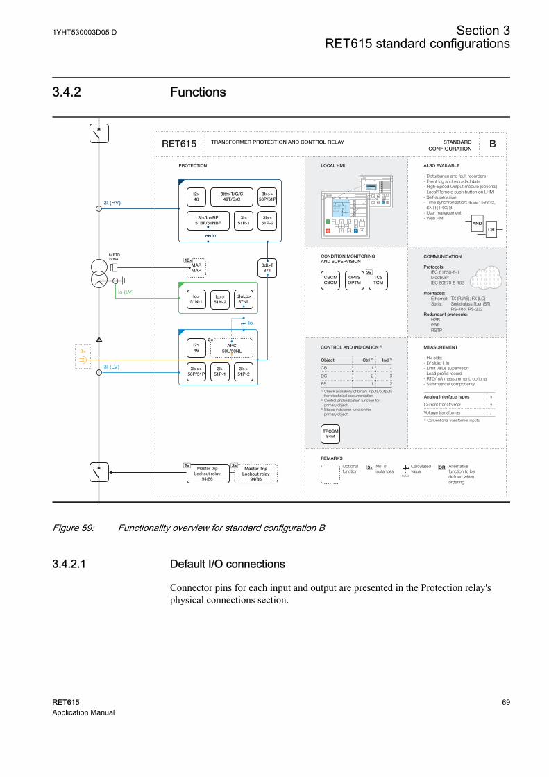
3.4.2 Functions
Master tripLockout relay
94/86
Master TripLockout relay
94/86
3×2×
CONDITION MONITORING AND SUPERVISION
ALSO AVAILABLE
- Disturbance and fault recorders- Event log and recorded data- High-Speed Output module (optional)- Local/Remote push button on LHMI- Self-supervision- Time synchronization: IEEE 1588 v2,
SNTP, IRIG-B- User management- Web HMI
CONTROL AND INDICATION 1) MEASUREMENT
TRANSFORMER PROTECTION AND CONTROL RELAY
PROTECTION LOCAL HMI
Object Ctrl 2) Ind 3)
CB
DC
ES1) Check availability of binary inputs/outputs
from technical documentation2) Control and indication function for
primary object3) Status indication function for primary object
1 -
2 3
1 2
STANDARD CONFIGURATION
REMARKS
Optionalfunction
No. ofinstances
Alternative function to be defined when ordering
OR
Io/Uo
Calculatedvalue
3×
RL
ClearESCI
O
Configuration ASystemHMITimeAuthorization
RL
ClearESCI
O
U12 0. 0 kVP 0.00 kWQ 0.00 kVAr
IL2 0 A
A
COMMUNICATION
Protocols: IEC 61850-8-1 Modbus®
IEC 60870-5-103 Interfaces: Ethernet: TX (RJ45), FX (LC) Serial: Serial glass fiber (ST), RS-485, RS-232Redundant protocols: HSR PRP RSTP
RET615
ORAND
- HV side: I - LV side: I, Io- Limit value supervision- Load profile record- RTD/mA measurement, optional- Symmetrical components
B
Analog interface types 1)
Current transformer
1) Conventional transformer inputs
Voltage transformer
7
-
I2>46
3I>>>50P/51P
3I>/Io>BF51BF/51NBF
3I>51P-1
3I>>51P-2
3dI>T87T
I2>46
3×ARC
50L/50NL
2×TCSTCM
CBCMCBCM
OPTSOPTM
3I>>51P-2
3I>>>50P/51P
3I>51P-1
Io>51N-1
Io>>51N-2
dIoLo>87NL
18×MAPMAP
3Ith>T/G/C49T/G/C
Io
Io
Io (LV)
TPOSM84M
6×RTD2×mA
3×
3I (HV)
3I (LV)
GUID-4317DA1C-AA8E-4715-8055-664CEA9F1B06 V1 EN
Figure 59: Functionality overview for standard configuration B
3.4.2.1 Default I/O connections
Connector pins for each input and output are presented in the Protection relay'sphysical connections section.
1YHT530003D05 D Section 3RET615 standard configurations
RET615 69Application Manual
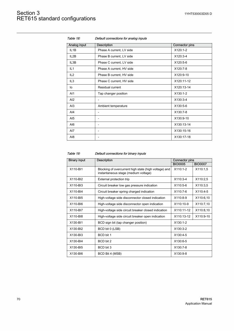
Table 18: Default connections for analog inputs
Analog input Description Connector pinsIL1B Phase A current, LV side X120:1-2
IL2B Phase B current, LV side X120:3-4
IL3B Phase C current, LV side X120:5-6
IL1 Phase A current, HV side X120:7-8
IL2 Phase B current, HV side X120:9-10
IL3 Phase C current, HV side X120:11-12
Io Residual current X120:13-14
AI1 Tap changer position X130:1-2
AI2 - X130:3-4
AI3 Ambient temperature X130:5-6
AI4 - X130:7-8
AI5 - X130:9-10
AI6 - X130:13-14
AI7 - X130:15-16
AI8 - X130:17-18
Table 19: Default connections for binary inputs
Binary input Description Connector pinsBIO0005 BIO0007
X110-BI1 Blocking of overcurrent high state (high voltage) andinstantaneous stage (medium voltage)
X110:1-2 X110:1,5
X110-BI2 External protection trip X110:3-4 X110:2,5
X110-BI3 Circuit breaker low gas pressure indication X110:5-6 X110:3,5
X110-BI4 Circuit breaker spring charged indication X110:7-6 X110:4-5
X110-BI5 High-voltage side disconnector closed indication X110:8-9 X110:6,10
X110-BI6 High-voltage side disconnector open indication X110:10-9 X110:7,10
X110-BI7 High-voltage side circuit breaker closed indication X110:11-12 X110:8,10
X110-BI8 High-voltage side circuit breaker open indication X110:13-12 X110:9-10
X130-BI1 BCD sign bit (tap changer position) X130:1-2
X130-BI2 BCD bit 0 (LSB) X130:3-2
X130-BI3 BCD bit 1 X130:4-5
X130-BI4 BCD bit 2 X130:6-5
X130-BI5 BCD bit 3 X130:7-8
X130-BI6 BCD Bit 4 (MSB) X130:9-8
Section 3 1YHT530003D05 DRET615 standard configurations
70 RET615Application Manual
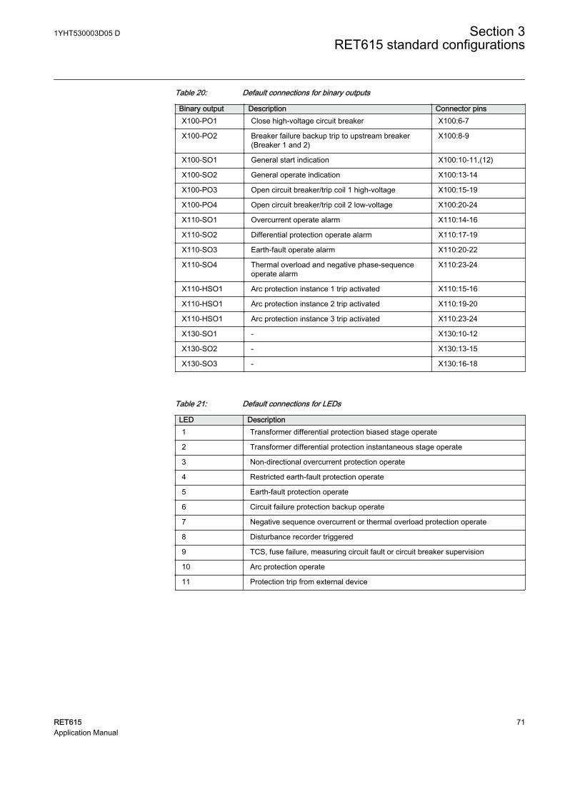
Table 20: Default connections for binary outputs
Binary output Description Connector pinsX100-PO1 Close high-voltage circuit breaker X100:6-7
X100-PO2 Breaker failure backup trip to upstream breaker(Breaker 1 and 2)
X100:8-9
X100-SO1 General start indication X100:10-11,(12)
X100-SO2 General operate indication X100:13-14
X100-PO3 Open circuit breaker/trip coil 1 high-voltage X100:15-19
X100-PO4 Open circuit breaker/trip coil 2 low-voltage X100:20-24
X110-SO1 Overcurrent operate alarm X110:14-16
X110-SO2 Differential protection operate alarm X110:17-19
X110-SO3 Earth-fault operate alarm X110:20-22
X110-SO4 Thermal overload and negative phase-sequenceoperate alarm
X110:23-24
X110-HSO1 Arc protection instance 1 trip activated X110:15-16
X110-HSO1 Arc protection instance 2 trip activated X110:19-20
X110-HSO1 Arc protection instance 3 trip activated X110:23-24
X130-SO1 - X130:10-12
X130-SO2 - X130:13-15
X130-SO3 - X130:16-18
Table 21: Default connections for LEDs
LED Description1 Transformer differential protection biased stage operate
2 Transformer differential protection instantaneous stage operate
3 Non-directional overcurrent protection operate
4 Restricted earth-fault protection operate
5 Earth-fault protection operate
6 Circuit failure protection backup operate
7 Negative sequence overcurrent or thermal overload protection operate
8 Disturbance recorder triggered
9 TCS, fuse failure, measuring circuit fault or circuit breaker supervision
10 Arc protection operate
11 Protection trip from external device
1YHT530003D05 D Section 3RET615 standard configurations
RET615 71Application Manual
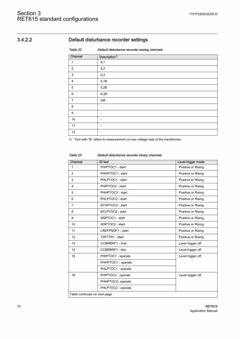
3.4.2.2 Default disturbance recorder settings
Table 22: Default disturbance recorder analog channels
Channel Description1)
1 IL1
2 IL2
3 IL3
4 IL1B
5 IL2B
6 IL3B
7 IoB
8 -
9 -
10 -
11 -
12 -
1) Text with “B” refers to measurement on low-voltage side of the transformer
Table 23: Default disturbance recorder binary channels
Channel ID text Level trigger mode1 PHIPTOC1 - start Positive or Rising
2 PHHPTOC1 - start Positive or Rising
3 PHLPTOC1 - start Positive or Rising
4 PHIPTOC2 - start Positive or Rising
5 PHHPTOC2 - start Positive or Rising
6 PHLPTOC2 - start Positive or Rising
7 EFHPTOC2 - start Positive or Rising
8 EFLPTOC2 - start Positive or Rising
9 NSPTOC1 - start Positive or Rising
10 NSPTOC2 - start Positive or Rising
11 LREFPNDF1 - start Positive or Rising
12 T2PTTR1 - start Positive or Rising
13 CCBRBRF1 - trret Level trigger off
14 CCBRBRF1 - trbu Level trigger off
15 PHIPTOC1 - operate Level trigger off
PHHPTOC1 - operate
PHLPTOC1 - operate
16 PHIPTOC2 - operate Level trigger off
PHHPTOC2- operate
PHLPTOC2 - operate
Table continues on next page
Section 3 1YHT530003D05 DRET615 standard configurations
72 RET615Application Manual
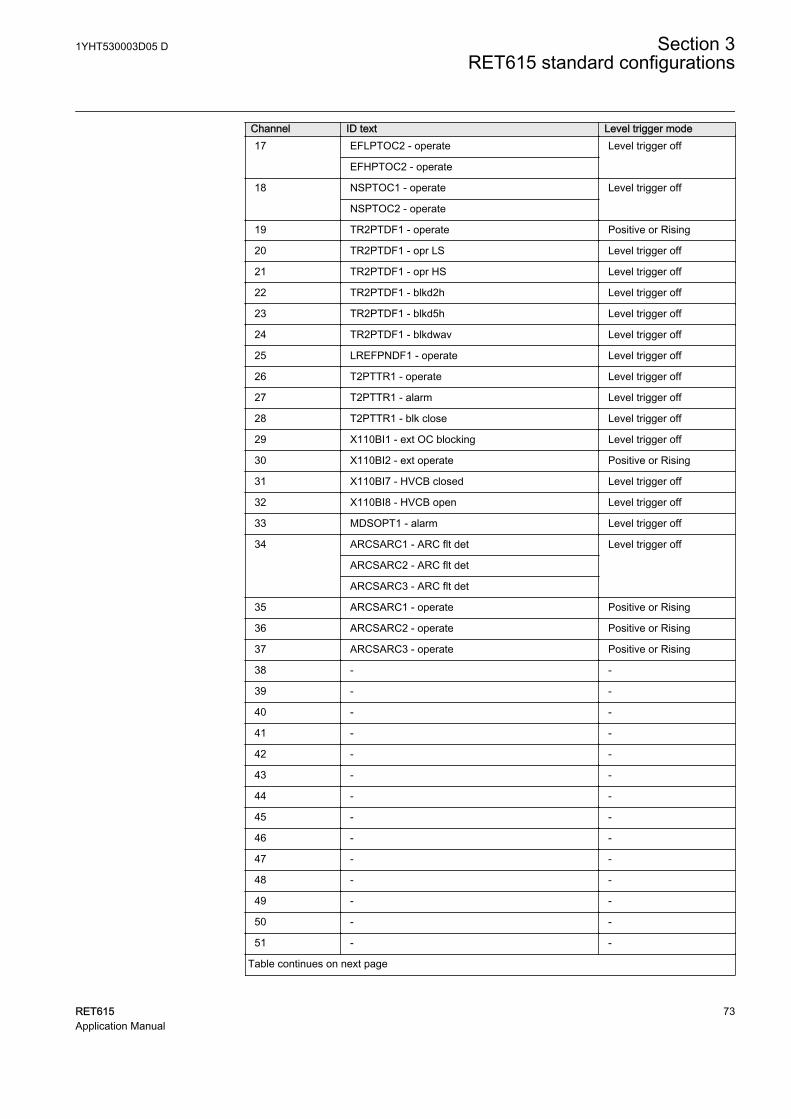
Channel ID text Level trigger mode17 EFLPTOC2 - operate Level trigger off
EFHPTOC2 - operate
18 NSPTOC1 - operate Level trigger off
NSPTOC2 - operate
19 TR2PTDF1 - operate Positive or Rising
20 TR2PTDF1 - opr LS Level trigger off
21 TR2PTDF1 - opr HS Level trigger off
22 TR2PTDF1 - blkd2h Level trigger off
23 TR2PTDF1 - blkd5h Level trigger off
24 TR2PTDF1 - blkdwav Level trigger off
25 LREFPNDF1 - operate Level trigger off
26 T2PTTR1 - operate Level trigger off
27 T2PTTR1 - alarm Level trigger off
28 T2PTTR1 - blk close Level trigger off
29 X110BI1 - ext OC blocking Level trigger off
30 X110BI2 - ext operate Positive or Rising
31 X110BI7 - HVCB closed Level trigger off
32 X110BI8 - HVCB open Level trigger off
33 MDSOPT1 - alarm Level trigger off
34 ARCSARC1 - ARC flt det Level trigger off
ARCSARC2 - ARC flt det
ARCSARC3 - ARC flt det
35 ARCSARC1 - operate Positive or Rising
36 ARCSARC2 - operate Positive or Rising
37 ARCSARC3 - operate Positive or Rising
38 - -
39 - -
40 - -
41 - -
42 - -
43 - -
44 - -
45 - -
46 - -
47 - -
48 - -
49 - -
50 - -
51 - -
Table continues on next page
1YHT530003D05 D Section 3RET615 standard configurations
RET615 73Application Manual
Channel ID text Level trigger mode52 - -
53 - -
54 - -
55 - -
56 - -
57 - -
58 - -
59 - -
60 - -
61 - -
62 - -
63 - -
64 - -
3.4.3 Functional diagrams
The functional diagrams describe the default input, output, alarm LED and function-to-function connections. The default connections can be viewed and changed withPCM600 according to the application requirements.
The analog channels have fixed connections to the different function blocks inside theprotection relay’s standard configuration. However, the 12 analog channels availablefor the disturbance recorder function are freely selectable as a part of the disturbancerecorder’s parameter settings.
The high-voltage and low-voltage side phase currents to the protection relay are fedfrom a current transformer. The neutral current to the protection relay is measuredbetween the star point of the transformer and grounding.
The protection relay offers six different setting groups which can be set based onindividual needs. Each group can be activated or deactivated using the setting groupsettings available in the protection relay.
Depending on the communication protocol the required function block needs to beinstantiated in the configuration.
3.4.3.1 Functional diagrams for protection
The functional diagrams describe the protection relay's protection functionality indetail and according to the factory set default connections.
The stabilized and instantaneous differential protection for two-winding transformersTR2PTDF1 provides protection of power transformer unit including, for example,winding short-circuit and inter-turn faults. The protection relay compares the phasecurrents on both sides of the object to be protected. If the differential current of the
Section 3 1YHT530003D05 DRET615 standard configurations
74 RET615Application Manual

phase currents in one of the phases exceed the setting of the stabilized operationcharacteristic or the instantaneous protection stage of the function, the functionprovides an operate signal. All operate signals from the functions are connected to themaster trips as well as to alarm LEDs.
For transformers having an online tap changer, the tap position information isrecommended to be used in differential protection, as the ratio difference of tapchanger movements can be corrected in TR2PTDF1.
TR2PTDF1BLOCKBLK_OPR_LSBLK_OPR_HS
OPERATEOPR_LSOPR_HSBLKD2HBLKD5H
BLKDWAV
TR2PTDF1_OPERATETR2PTDF1_OPR_LSTR2PTDF1_OPR_HSTR2PTDF1_BLKD2HTR2PTDF1_BLKD5HTR2PTDF1_BLKDWAV
GUID-5E7FC025-8746-46B6-90B0-4B45DD51618C V1 EN
Figure 60: Transformer differential protection function
Three non-directional overcurrent stages each are offered for overcurrent and short-circuit protection for high-voltage as well as low-voltage side of the transformer. Thehigh stage of high-voltage side PHHPTOC1 and instantaneous stage of low-voltageside PHIPTOC2 can be blocked by energizing the binary input X110:BI1. In addition,high stage of high-voltage side PHHPTOC1 is blocked by start of high stage of low-voltage side PHHPTOC2.
A selective backup overcurrent protection can be achieved by using blockingsbetween high-voltage side and low-voltage side overcurrent stages. This blockingscheme enables coordinated overlapping of overcurrent protection zones.
PHIPTOC1BLOCKENA_MULT
OPERATESTART
PHLPTOC1BLOCKENA_MULT
OPERATESTART
PHHPTOC1BLOCKENA_MULT
OPERATESTART
ORB1B2
O
OR6B1B2B3B4B5B6
O
PHIPTOC1_OPERATE
PHIPTOC1_OPERATE
PHLPTOC1_OPERATE
PHLPTOC1_OPERATE
PHHPTOC1_OPERATE
PHHPTOC1_OPERATE
PHIPTOC1_START
PHLPTOC1_START
PHHPTOC1_STARTPHHPTOC2_START
X110_BI1_EXT_OC_BLOCKING
PHxPTOC_OPERATE_HVSIDE
GUID-423ABA1C-6C9C-4FA2-83F6-0B019418E898 V1 EN
Figure 61: High-voltage side overcurrent protection function
1YHT530003D05 D Section 3RET615 standard configurations
RET615 75Application Manual

PHIPTOC2BLOCKENA_MULT
OPERATESTART
PHHPTOC2BLOCKENA_MULT
OPERATESTART
PHLPTOC2BLOCKENA_MULT
OPERATESTART
OR6B1B2B3B4B5B6
O
PHIPTOC2_OPERATE
PHIPTOC2_OPERATE
PHLPTOC2_OPERATE
PHLPTOC2_OPERATE
PHHPTOC2_OPERATE
PHHPTOC2_OPERATE
PHLPTOC2_START
PHIPTOC2_START
PHHPTOC2_START
X110_BI1_EXT_OC_BLOCKING
PHxPTOC_OPERATE_LVSIDE
GUID-87D5B11E-B4D0-4AA7-A629-07853B38061E V1 EN
Figure 62: Low-voltage side overcurrent protection function
Two stages are offered for non-directional earth-fault protection and this measures theneutral current from low-voltage side.
EFHPTOC2BLOCKENA_MULT
OPERATESTART
EFLPTOC2BLOCKENA_MULT
OPERATESTART
ORB1B2
O
EFLPTOC2_OPERATE
EFLPTOC2_OPERATE
EFHPTOC2_OPERATE
EFHPTOC2_OPERATE
EFHPTOC2_START
EFLPTOC2_START
EFxPTOC_OPERATE_LVSIDE
GUID-E8E19B5F-90B9-487C-A546-F72E1EB0135F V1 EN
Figure 63: Low-voltage side earth-fault protection function
The configuration includes numerically stabilized low-impedance restricted earth-fault protection function for low-voltage side of two-winding power transformersLREFPNDF1. The numerical differential current stage operates exclusively on earth-faults occurring in the protected area, that is, in the area between the phase and neutralcurrent transformers. An earth fault in this area appears as a differential currentbetween the residual current of the phase currents and the neutral current of theconductor between the star-point of the transformer and earth.
Section 3 1YHT530003D05 DRET615 standard configurations
76 RET615Application Manual
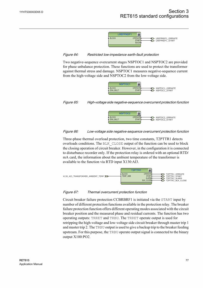
LREFPNDF1BLOCK OPERATE
STARTBLK2H
LREFPNDF1_OPERATELREFPNDF1_START
GUID-2EDD6841-113A-462C-89B3-A25B129228A1 V1 EN
Figure 64: Restricted low-impedance earth-fault protection
Two negative-sequence overcurrent stages NSPTOC1 and NSPTOC2 are providedfor phase unbalance protection. These functions are used to protect the transformeragainst thermal stress and damage. NSPTOC1 measures negative-sequence currentfrom the high-voltage side and NSPTOC2 from the low-voltage side.
NSPTOC1BLOCKENA_MULT
OPERATESTART
NSPTOC1_OPERATENSPTOC1_START
GUID-D9D3638E-5B0C-4857-96B9-843D5E9AF4CE V1 EN
Figure 65: High-voltage side negative-sequence overcurrent protection function
NSPTOC2BLOCKENA_MULT
OPERATESTART
NSPTOC2_OPERATENSPTOC2_START
GUID-B20A0185-D86F-4E95-988D-2DCF8F5B6A5F V1 EN
Figure 66: Low-voltage side negative-sequence overcurrent protection function
Three-phase thermal overload protection, two time constants, T2PTTR1 detectsoverloads conditions. The BLK_CLOSE output of the function can be used to blockthe closing operation of circuit breaker. However, in the configuration it is connectedto disturbance recorder only. If the protection relay is ordered with an optional RTD/mA card, the information about the ambient temperature of the transformer isavailable to the function via RTD input X130:AI3.
T2PTTR1BLOCKTEMP_AMB
OPERATESTARTALARM
BLK_CLOSE
T2PTTR1_OPERATET2PTTR1_STARTX130_AI3_TRANSFORMER_AMBIENT_TEMPT2PTTR1_ALARMT2PTTR1_BLK_CLOSE
GUID-3021F7E5-67BD-4E06-9F6E-2E3AEFB6E1F1 V1 EN
Figure 67: Thermal overcurrent protection function
Circuit breaker failure protection CCBRBRF1 is initiated via the START input bynumber of different protection functions available in the protection relay. The breakerfailure protection function offers different operating modes associated with the circuitbreaker position and the measured phase and residual currents. The function has twooperating outputs: TRRET and TRBU. The TRRET operate output is used forretripping the high-voltage and low-voltage side circuit breaker through master trip 1and master trip 2. The TRBU output is used to give a backup trip to the breaker feedingupstream. For this purpose, the TRBU operate output signal is connected to the binaryoutput X100:PO2.
1YHT530003D05 D Section 3RET615 standard configurations
RET615 77Application Manual
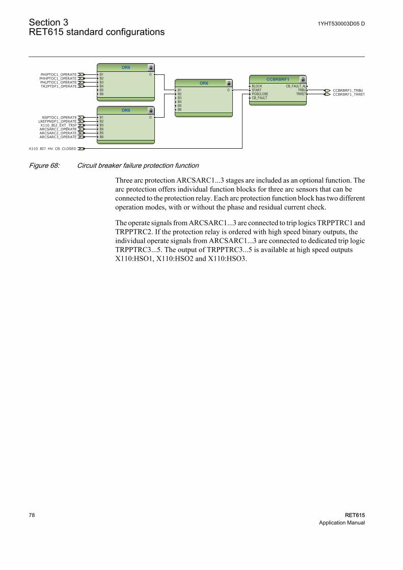
CCBRBRF1BLOCKSTARTPOSCLOSECB_FAULT
CB_FAULT_ALTRBU
TRRET
OR6B1B2B3B4B5B6
O
OR6B1B2B3B4B5B6
O
OR6B1B2B3B4B5B6
O CCBRBRF1_TRBU
X110_BI7_HV_CB_CLOSED
PHIPTOC1_OPERATE
PHLPTOC1_OPERATEPHHPTOC1_OPERATE
LREFPNDF1_OPERATE
CCBRBRF1_TRRET
NSPTOC1_OPERATE
TR2PTDF1_OPERATE
X110_BI2_EXT_TRIPARCSARC1_OPERATEARCSARC2_OPERATEARCSARC3_OPERATE
GUID-09DC4420-0E49-4236-BF14-900BA7F76D8B V1 EN
Figure 68: Circuit breaker failure protection function
Three arc protection ARCSARC1...3 stages are included as an optional function. Thearc protection offers individual function blocks for three arc sensors that can beconnected to the protection relay. Each arc protection function block has two differentoperation modes, with or without the phase and residual current check.
The operate signals from ARCSARC1...3 are connected to trip logics TRPPTRC1 andTRPPTRC2. If the protection relay is ordered with high speed binary outputs, theindividual operate signals from ARCSARC1...3 are connected to dedicated trip logicTRPPTRC3...5. The output of TRPPTRC3...5 is available at high speed outputsX110:HSO1, X110:HSO2 and X110:HSO3.
Section 3 1YHT530003D05 DRET615 standard configurations
78 RET615Application Manual
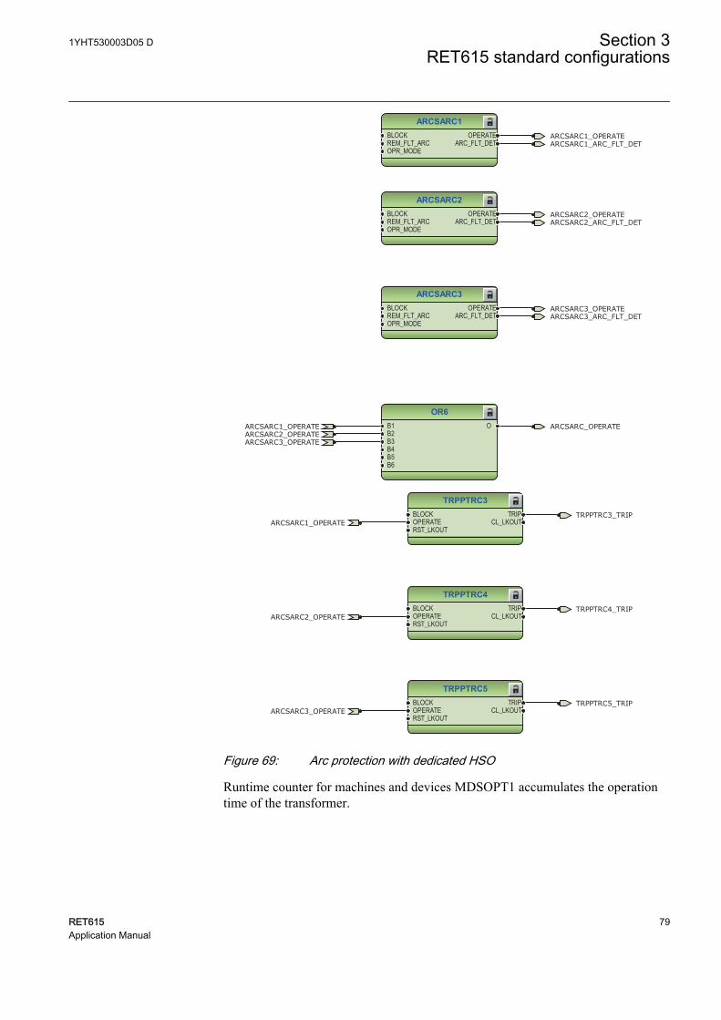
ARCSARC1BLOCKREM_FLT_ARCOPR_MODE
OPERATEARC_FLT_DET
ARCSARC2BLOCKREM_FLT_ARCOPR_MODE
OPERATEARC_FLT_DET
ARCSARC3BLOCKREM_FLT_ARCOPR_MODE
OPERATEARC_FLT_DET
OR6B1B2B3B4B5B6
O
ARCSARC1_OPERATE
ARCSARC1_OPERATE
ARCSARC2_OPERATE
ARCSARC2_OPERATE
ARCSARC3_OPERATE
ARCSARC3_OPERATE
ARCSARC1_ARC_FLT_DET
ARCSARC2_ARC_FLT_DET
ARCSARC3_ARC_FLT_DET
ARCSARC_OPERATE
GUID-7113AEEC-FC3D-4DB8-9A21-A1B10EEB890D V1 EN
TRPPTRC3BLOCKOPERATERST_LKOUT
TRIPCL_LKOUT
TRPPTRC4BLOCKOPERATERST_LKOUT
TRIPCL_LKOUT
TRPPTRC5BLOCKOPERATERST_LKOUT
TRIPCL_LKOUT
TRPPTRC3_TRIP
TRPPTRC4_TRIP
TRPPTRC5_TRIP
ARCSARC1_OPERATE
ARCSARC2_OPERATE
ARCSARC3_OPERATE
GUID-D79DEB64-F5C8-456E-855B-9CBC836E4BA1 V1 EN
Figure 69: Arc protection with dedicated HSO
Runtime counter for machines and devices MDSOPT1 accumulates the operationtime of the transformer.
1YHT530003D05 D Section 3RET615 standard configurations
RET615 79Application Manual
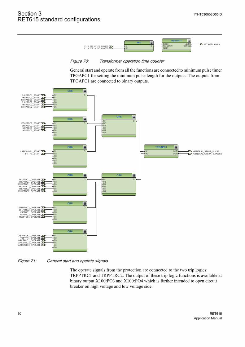
MDSOPT1BLOCKPOS_ACTIVERESET
ALARMWARNING
ANDB1B2
OX110_BI7_HV_CB_CLOSEDX110_BI5_HV_DC_CLOSED
MDSOPT1_ALARM
GUID-D2187A1A-9E36-46D0-B25A-F704DE9CFA29 V1 EN
Figure 70: Transformer operation time counter
General start and operate from all the functions are connected to minimum pulse timerTPGAPC1 for setting the minimum pulse length for the outputs. The outputs fromTPGAPC1 are connected to binary outputs.
OR6B1B2B3B4B5B6
O
OR6B1B2B3B4B5B6
O
OR6B1B2B3B4B5B6
O
OR6B1B2B3B4B5B6
O
OR6B1B2B3B4B5B6
O
OR6B1B2B3B4B5B6
O
OR6B1B2B3B4B5B6
O
OR6B1B2B3B4B5B6
O
TPGAPC1IN1IN2
OUT1OUT2
GENERAL_START_PULSEGENERAL_OPERATE_PULSE
PHIPTOC1_OPERATEPHLPTOC1_OPERATE
PHHPTOC1_OPERATE
LREFPNDF1_OPERATE
NSPTOC1_OPERATE
TR2PTDF1_OPERATE
ARCSARC1_OPERATEARCSARC2_OPERATEARCSARC3_OPERATE
PHIPTOC2_OPERATEPHLPTOC2_OPERATE
PHHPTOC2_OPERATE
T2PTTR1_OPERATE
NSPTOC2_OPERATE
EFLPTOC2_OPERATEEFHPTOC2_OPERATE
PHIPTOC1_STARTPHLPTOC1_START
PHHPTOC1_STARTPHLPTOC2_STARTPHIPTOC2_STARTPHHPTOC2_START
EFHPTOC2_STARTEFLPTOC2_STARTNSPTOC1_STARTNSPTOC2_START
LREFPNDF1_STARTT2PTTR1_START
GUID-2A744614-6585-47E9-9DB2-1B6B1119BDA0 V1 EN
Figure 71: General start and operate signals
The operate signals from the protection are connected to the two trip logics:TRPPTRC1 and TRPPTRC2. The output of these trip logic functions is available atbinary output X100:PO3 and X100:PO4 which is further intended to open circuitbreaker on high voltage and low voltage side.
Section 3 1YHT530003D05 DRET615 standard configurations
80 RET615Application Manual
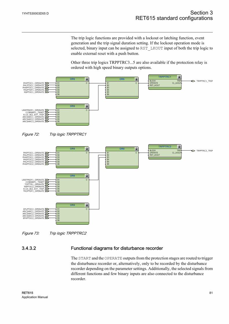
The trip logic functions are provided with a lockout or latching function, eventgeneration and the trip signal duration setting. If the lockout operation mode isselected, binary input can be assigned to RST_LKOUT input of both the trip logic toenable external reset with a push button.
Other three trip logics TRPPTRC3...5 are also available if the protection relay isordered with high speed binary outputs options.
TRPPTRC1BLOCKOPERATERST_LKOUT
TRIPCL_LKOUT
OR6B1B2B3B4B5B6
O
OR6B1B2B3B4B5B6
O
OR6B1B2B3B4B5B6
OTRPPTRC1_TRIP
PHIPTOC1_OPERATEPHLPTOC1_OPERATEPHHPTOC1_OPERATE
LREFPNDF1_OPERATECCBRBRF1_TRRET
NSPTOC1_OPERATETR2PTDF1_OPERATE
X110_BI2_EXT_TRIPARCSARC1_OPERATEARCSARC2_OPERATEARCSARC3_OPERATE
GUID-709CA514-FCE3-4352-B451-AE2F41408B9D V1 EN
Figure 72: Trip logic TRPPTRC1
OR6B1B2B3B4B5B6
O
OR6B1B2B3B4B5B6
O
OR6B1B2B3B4B5B6
O
OR6B1B2B3B4B5B6
O
TRPPTRC2BLOCKOPERATERST_LKOUT
TRIPCL_LKOUT
TRPPTRC2_TRIPPHIPTOC1_OPERATEPHLPTOC1_OPERATEPHHPTOC1_OPERATE
LREFPNDF1_OPERATECCBRBRF1_TRRET
TR2PTDF1_OPERATEX110_BI2_EXT_TRIP
ARCSARC1_OPERATEARCSARC2_OPERATEARCSARC3_OPERATE
PHIPTOC2_OPERATEPHLPTOC2_OPERATEPHHPTOC2_OPERATE
T2PTTR1_OPERATENSPTOC2_OPERATE
EFLPTOC2_OPERATE
EFHPTOC2_OPERATE
GUID-035A4510-CA4B-4A7D-8EB7-41C7DF38A0F8 V1 EN
Figure 73: Trip logic TRPPTRC2
3.4.3.2 Functional diagrams for disturbance recorder
The START and the OPERATE outputs from the protection stages are routed to triggerthe disturbance recorder or, alternatively, only to be recorded by the disturbancerecorder depending on the parameter settings. Additionally, the selected signals fromdifferent functions and few binary inputs are also connected to the disturbancerecorder.
1YHT530003D05 D Section 3RET615 standard configurations
RET615 81Application Manual
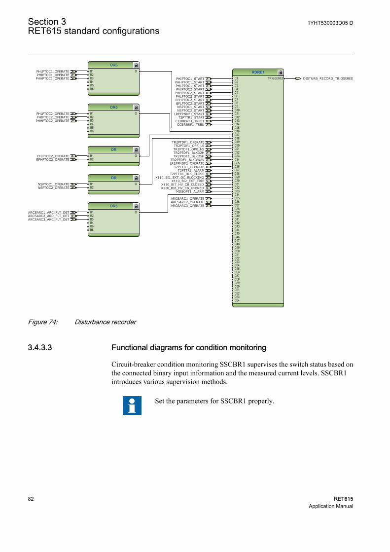
RDRE1C1C2C3C4C5C6C7C8C9C10C11C12C13C14C15C16C17C18C19C20C21C22C23C24C25C26C27C28C29C30C31C32C33C34C35C36C37C38C39C40C41C42C43C44C45C46C47C48C49C50C51C52C53C54C55C56C57C58C59C60C61C62C63C64
TRIGGERED
OR6B1B2B3B4B5B6
O
ORB1B2
O
ORB1B2
O
OR6B1B2B3B4B5B6
O
OR6B1B2B3B4B5B6
O
CCBRBRF1_TRBU
X110_BI8_HV_CB_OPENEDX110_BI7_HV_CB_CLOSED
PHIPTOC1_OPERATEPHLPTOC1_OPERATE
PHHPTOC1_OPERATE
LREFPNDF1_OPERATE
CCBRBRF1_TRRET
NSPTOC1_OPERATE
TR2PTDF1_OPERATE
X110_BI2_EXT_TRIP
ARCSARC1_OPERATEARCSARC2_OPERATEARCSARC3_OPERATE
PHIPTOC2_OPERATEPHLPTOC2_OPERATE
PHHPTOC2_OPERATE
T2PTTR1_OPERATE
NSPTOC2_OPERATE
EFLPTOC2_OPERATEEFHPTOC2_OPERATE
PHIPTOC1_START
PHLPTOC1_STARTPHHPTOC1_START
PHLPTOC2_START
PHIPTOC2_STARTPHHPTOC2_START
EFHPTOC2_STARTEFLPTOC2_STARTNSPTOC1_STARTNSPTOC2_START
LREFPNDF1_STARTT2PTTR1_START
X110_BI1_EXT_OC_BLOCKING
ARCSARC1_ARC_FLT_DETARCSARC2_ARC_FLT_DETARCSARC3_ARC_FLT_DET
TR2PTDF1_OPR_LSTR2PTDF1_OPR_HSTR2PTDF1_BLKD2HTR2PTDF1_BLKD5H
TR2PTDF1_BLKDWAV
T2PTTR1_ALARMT2PTTR1_BLK_CLOSE
MDSOPT1_ALARM
DISTURB_RECORD_TRIGGERED
GUID-04E48901-7F3A-496D-8F60-6855A5CF9F5B V1 EN
Figure 74: Disturbance recorder
3.4.3.3 Functional diagrams for condition monitoring
Circuit-breaker condition monitoring SSCBR1 supervises the switch status based onthe connected binary input information and the measured current levels. SSCBR1introduces various supervision methods.
Set the parameters for SSCBR1 properly.
Section 3 1YHT530003D05 DRET615 standard configurations
82 RET615Application Manual
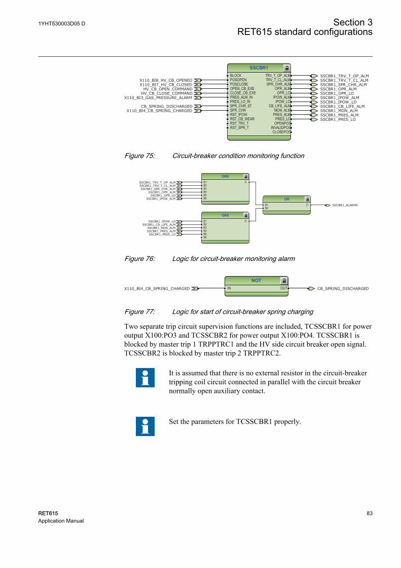
SSCBR1BLOCKPOSOPENPOSCLOSEOPEN_CB_EXECLOSE_CB_EXEPRES_ALM_INPRES_LO_INSPR_CHR_STSPR_CHRRST_IPOWRST_CB_WEARRST_TRV_TRST_SPR_T
TRV_T_OP_ALMTRV_T_CL_ALMSPR_CHR_ALM
OPR_ALMOPR_LO
IPOW_ALMIPOW_LO
CB_LIFE_ALMMON_ALM
PRES_ALMPRES_LO
OPENPOSINVALIDPOSCLOSEPOS
HV_CB_CLOSE_COMMANDHV_CB_OPEN_COMMAND
X110_BI8_HV_CB_OPENEDX110_BI7_HV_CB_CLOSED
X110_BI3_GAS_PRESSURE_ALARM
X110_BI4_CB_SPRING_CHARGEDCB_SPRING_DISCHARGED
SSCBR1_IPOW_LOSSCBR1_CB_LIFE_ALMSSCBR1_MON_ALMSSCBR1_PRES_ALMSSCBR1_PRES_LO
SSCBR1_TRV_T_CL_ALMSSCBR1_TRV_T_OP_ALM
SSCBR1_SPR_CHR_ALMSSCBR1_OPR_ALMSSCBR1_OPR_LOSSCBR1_IPOW_ALM
GUID-F547A179-F83A-4DD1-94F1-A70CDAF3E02A V1 EN
Figure 75: Circuit-breaker condition monitoring function
OR6B1B2B3B4B5B6
O
ORB1B2
O
OR6B1B2B3B4B5B6
O
SSCBR1_IPOW_LOSSCBR1_CB_LIFE_ALM
SSCBR1_MON_ALMSSCBR1_PRES_ALM
SSCBR1_PRES_LO
SSCBR1_TRV_T_CL_ALMSSCBR1_TRV_T_OP_ALM
SSCBR1_SPR_CHR_ALMSSCBR1_OPR_ALM
SSCBR1_OPR_LOSSCBR1_IPOW_ALM
SSCBR1_ALARMS
GUID-C76E0DAA-7ADC-484F-AAE8-0795AB05FA1A V1 EN
Figure 76: Logic for circuit-breaker monitoring alarm
NOTIN OUTX110_BI4_CB_SPRING_CHARGED CB_SPRING_DISCHARGED
GUID-1F158DE7-1250-499A-98F9-41606C3F0587 V1 EN
Figure 77: Logic for start of circuit-breaker spring charging
Two separate trip circuit supervision functions are included, TCSSCBR1 for poweroutput X100:PO3 and TCSSCBR2 for power output X100:PO4. TCSSCBR1 isblocked by master trip 1 TRPPTRC1 and the HV side circuit breaker open signal.TCSSCBR2 is blocked by master trip 2 TRPPTRC2.
It is assumed that there is no external resistor in the circuit-breakertripping coil circuit connected in parallel with the circuit breakernormally open auxiliary contact.
Set the parameters for TCSSCBR1 properly.
1YHT530003D05 D Section 3RET615 standard configurations
RET615 83Application Manual
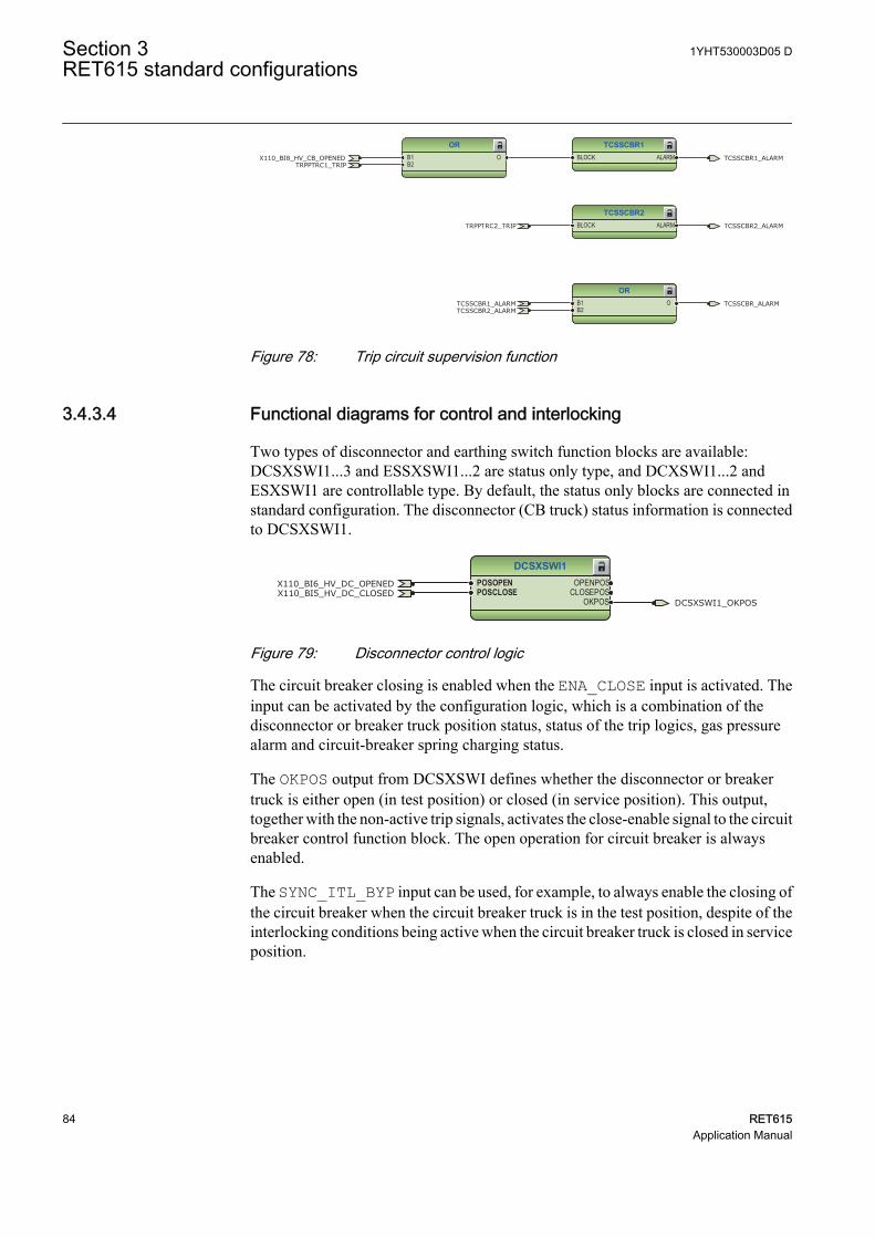
ORB1B2
OTCSSCBR1_ALARMTCSSCBR2_ALARM
TCSSCBR_ALARM
TCSSCBR1BLOCK ALARM
ORB1B2
OTRPPTRC1_TRIP
X110_BI8_HV_CB_OPENED TCSSCBR1_ALARM
TCSSCBR2BLOCK ALARMTRPPTRC2_TRIP TCSSCBR2_ALARM
GUID-CFDCE352-3155-4397-89AB-8284B9F137E1 V1 EN
Figure 78: Trip circuit supervision function
3.4.3.4 Functional diagrams for control and interlocking
Two types of disconnector and earthing switch function blocks are available:DCSXSWI1...3 and ESSXSWI1...2 are status only type, and DCXSWI1...2 andESXSWI1 are controllable type. By default, the status only blocks are connected instandard configuration. The disconnector (CB truck) status information is connectedto DCSXSWI1.
DCSXSWI1POSOPENPOSCLOSE
OPENPOSCLOSEPOS
OKPOS DCSXSWI1_OKPOS
X110_BI6_HV_DC_OPENEDX110_BI5_HV_DC_CLOSED
GUID-1BB8E1CC-02DB-4419-9A59-5DF20B6D5BCA V1 EN
Figure 79: Disconnector control logic
The circuit breaker closing is enabled when the ENA_CLOSE input is activated. Theinput can be activated by the configuration logic, which is a combination of thedisconnector or breaker truck position status, status of the trip logics, gas pressurealarm and circuit-breaker spring charging status.
The OKPOS output from DCSXSWI defines whether the disconnector or breakertruck is either open (in test position) or closed (in service position). This output,together with the non-active trip signals, activates the close-enable signal to the circuitbreaker control function block. The open operation for circuit breaker is alwaysenabled.
The SYNC_ITL_BYP input can be used, for example, to always enable the closing ofthe circuit breaker when the circuit breaker truck is in the test position, despite of theinterlocking conditions being active when the circuit breaker truck is closed in serviceposition.
Section 3 1YHT530003D05 DRET615 standard configurations
84 RET615Application Manual
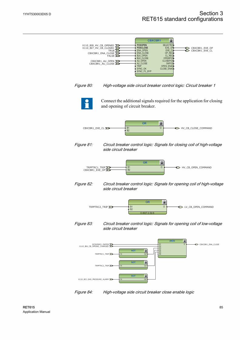
CBXCBR1POSOPENPOSCLOSEENA_OPENENA_CLOSEBLK_OPENBLK_CLOSEAU_OPENAU_CLOSETRIPSYNC_OKSYNC_ITL_BYP
SELECTEDEXE_OPEXE_CL
OP_REQCL_REQ
OPENPOSCLOSEPOS
OKPOSOPEN_ENAD
CLOSE_ENAD
TRUECBXCBR1_ENA_CLOSE
CBXCBR1_EXE_OPCBXCBR1_EXE_CL
X110_BI8_HV_CB_OPENEDX110_BI7_HV_CB_CLOSED
FALSE
CBXCBR1_AU_OPENCBXCBR1_AU_CLOSE
GUID-16A33522-924B-47F0-8118-3C73AF564E27 V2 EN
Figure 80: High-voltage side circuit breaker control logic: Circuit breaker 1
Connect the additional signals required for the application for closingand opening of circuit breaker.
ORB1B2
O HV_CB_CLOSE_COMMANDCBXCBR1_EXE_CL
GUID-1BDC25E1-152B-4955-8F43-455D8671B883 V1 EN
Figure 81: Circuit breaker control logic: Signals for closing coil of high-voltageside circuit breaker
ORB1B2
O HV_CB_OPEN_COMMANDTRPPTRC1_TRIPCBXCBR1_EXE_OP
GUID-08EEF2AF-73D6-4F4A-99F3-0CED238277B0 V1 EN
Figure 82: Circuit breaker control logic: Signals for opening coil of high-voltageside circuit breaker
OR
O:80|T:2.5|I:8
B1B2
O LV_CB_OPEN_COMMANDTRPPTRC2_TRIP
GUID-9972EA31-867F-4AEF-A079-056A670F0E84 V1 EN
Figure 83: Circuit breaker control logic: Signals for opening coil of low-voltageside circuit breaker
NOTIN OUT
AND6B1B2B3B4B5B6
O
NOTIN OUT
NOTIN OUT
TRPPTRC1_TRIP
CBXCBR1_ENA_CLOSE
X110_BI3_GAS_PRESSURE_ALARM
TRPPTRC2_TRIP
DCSXSWI1_OKPOSX110_BI4_CB_SPRING_CHARGED
GUID-14D14308-89FD-409B-8CDD-5E09BBD6263F V1 EN
Figure 84: High-voltage side circuit breaker close enable logic
1YHT530003D05 D Section 3RET615 standard configurations
RET615 85Application Manual
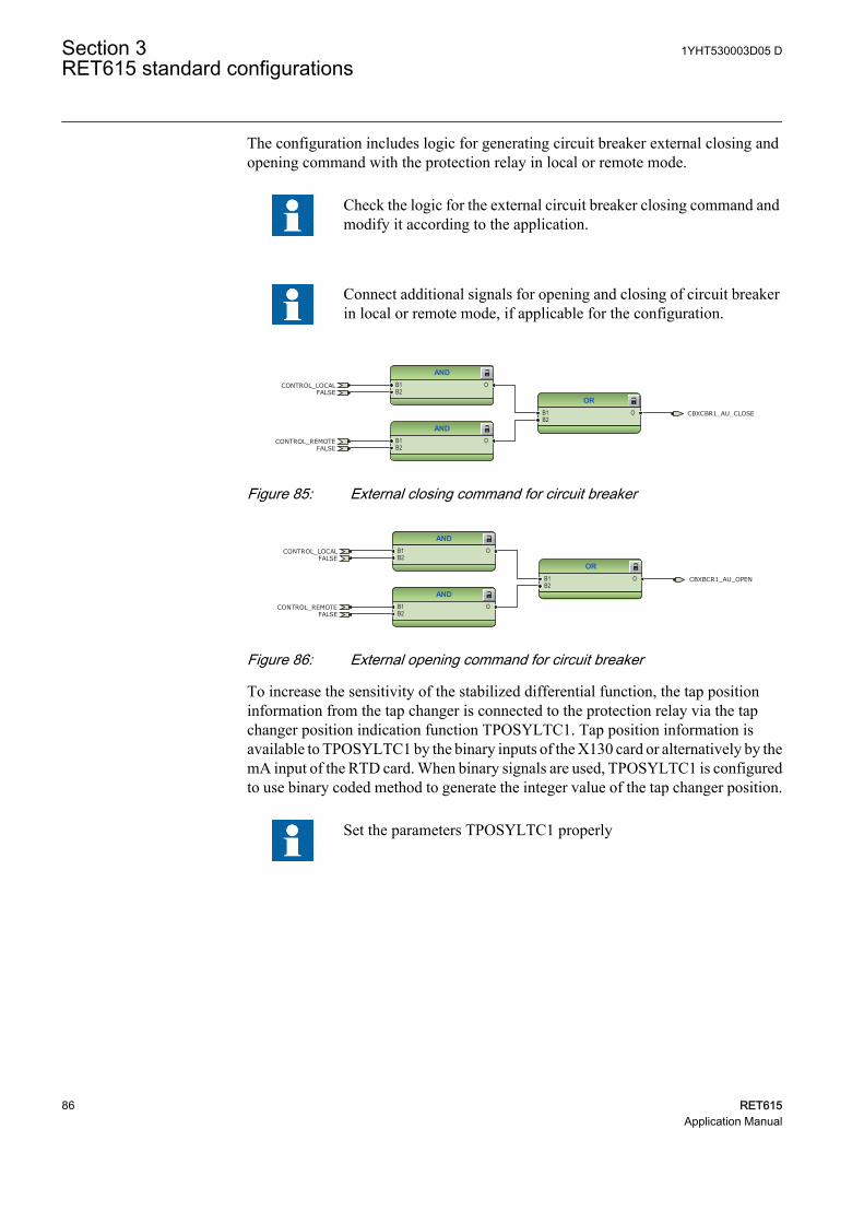
The configuration includes logic for generating circuit breaker external closing andopening command with the protection relay in local or remote mode.
Check the logic for the external circuit breaker closing command andmodify it according to the application.
Connect additional signals for opening and closing of circuit breakerin local or remote mode, if applicable for the configuration.
ANDB1B2
O
ANDB1B2
O
ORB1B2
O CBXCBR1_AU_CLOSE
CONTROL_LOCAL
CONTROL_REMOTE
FALSE
FALSE
GUID-DD88F26E-D0A5-48BE-A784-6C8DCDE6FDD6 V1 EN
Figure 85: External closing command for circuit breaker
ANDB1B2
O
ORB1B2
O
ANDB1B2
O
CBXBCR1_AU_OPEN
CONTROL_LOCAL
CONTROL_REMOTE
FALSE
FALSE
GUID-C97B82D6-31D0-4C83-A0CB-1F8AF321079D V1 EN
Figure 86: External opening command for circuit breaker
To increase the sensitivity of the stabilized differential function, the tap positioninformation from the tap changer is connected to the protection relay via the tapchanger position indication function TPOSYLTC1. Tap position information isavailable to TPOSYLTC1 by the binary inputs of the X130 card or alternatively by themA input of the RTD card. When binary signals are used, TPOSYLTC1 is configuredto use binary coded method to generate the integer value of the tap changer position.
Set the parameters TPOSYLTC1 properly
Section 3 1YHT530003D05 DRET615 standard configurations
86 RET615Application Manual
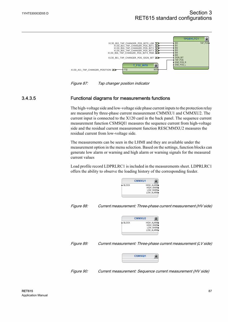
TPOSYLTC1BI0BI1BI2BI3BI4BI5SIGN_BITTAP_POSEND_POS_REND_POS_L
TAP_POS
T_F32_INT8F32 INT8
X130_BI2_TAP_CHANGER_POS_BIT0_LSBX130_BI3_TAP_CHANGER_POS_BIT1X130_BI4_TAP_CHANGER_POS_BIT2X130_BI5_TAP_CHANGER_POS_BIT3
X130_BI6_TAP_CHANGER_POS_BIT4_MSB
X130_BI1_TAP_CHANGER_POS_SIGN_BIT
X130_AI1_TAP_CHANGER_POSITION
GUID-D27EA867-71FE-4308-81D4-7C6195F24C71 V2 EN
Figure 87: Tap changer position indicator
3.4.3.5 Functional diagrams for measurements functions
The high-voltage side and low-voltage side phase current inputs to the protection relayare measured by three-phase current measurement CMMXU1 and CMMXU2. Thecurrent input is connected to the X120 card in the back panel. The sequence currentmeasurement function CSMSQI1 measures the sequence current from high-voltageside and the residual current measurement function RESCMMXU2 measures theresidual current from low-voltage side.
The measurements can be seen in the LHMI and they are available under themeasurement option in the menu selection. Based on the settings, function blocks cangenerate low alarm or warning and high alarm or warning signals for the measuredcurrent values
Load profile record LDPRLRC1 is included in the measurements sheet. LDPRLRC1offers the ability to observe the loading history of the corresponding feeder.
CMMXU1BLOCK HIGH_ALARM
HIGH_WARNLOW_WARN
LOW_ALARM
GUID-5EA5167A-04EB-453C-9600-9E92FD4FB094 V1 EN
Figure 88: Current measurement: Three-phase current measurement (HV side)
CMMXU2BLOCK HIGH_ALARM
HIGH_WARNLOW_WARN
LOW_ALARM
GUID-A4DAECB4-05E8-4F35-8C0D-DA154C2814AA V1 EN
Figure 89: Current measurement: Three-phase current measurement (LV side)
CSMSQI1
GUID-A7768DC7-2D42-4C9D-9D3C-B70095BCD227 V1 EN
Figure 90: Current measurement: Sequence current measurement (HV side)
1YHT530003D05 D Section 3RET615 standard configurations
RET615 87Application Manual
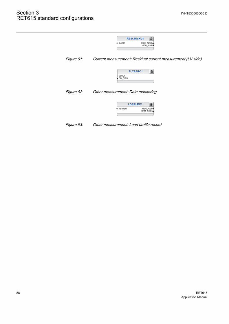
RESCMMXU1BLOCK HIGH_ALARM
HIGH_WARN
GUID-BA6B74B4-5CE4-45F5-B711-2536081AB468 V1 EN
Figure 91: Current measurement: Residual current measurement (LV side)
FLTRFRC1BLOCKCB_CLRD
GUID-4597E3E2-1C1B-4E88-B1D7-B6896FC54C55 V2 EN
Figure 92: Other measurement: Data monitoring
LDPRLRC1RSTMEM MEM_WARN
MEM_ALARM
GUID-6D450EBD-6D9D-40F9-8550-FBCE3AF767A6 V2 EN
Figure 93: Other measurement: Load profile record
Section 3 1YHT530003D05 DRET615 standard configurations
88 RET615Application Manual
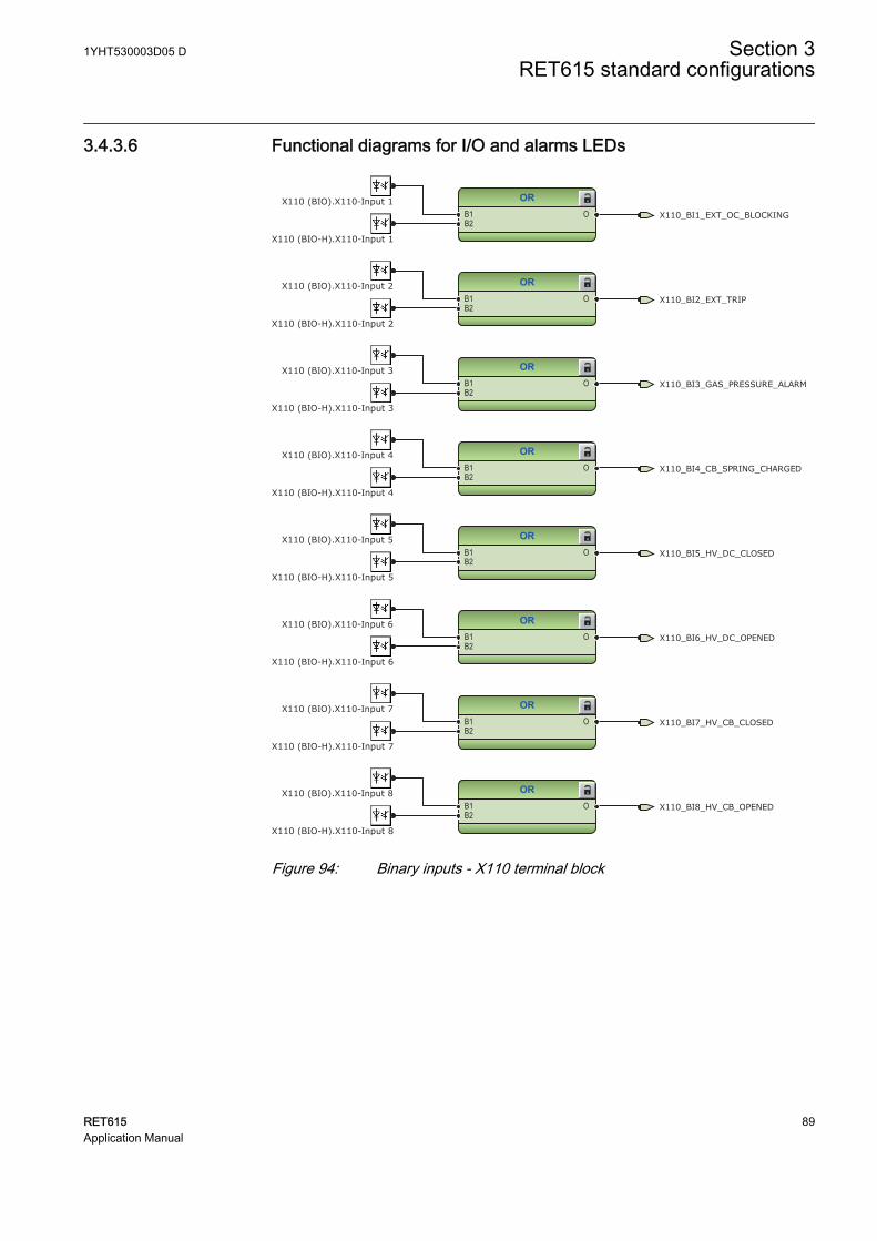
3.4.3.6 Functional diagrams for I/O and alarms LEDs
ORB1B2
O
ORB1B2
O
ORB1B2
O
ORB1B2
O
ORB1B2
O
ORB1B2
O
ORB1B2
O
ORB1B2
O X110_BI8_HV_CB_OPENED
X110_BI7_HV_CB_CLOSED
X110_BI3_GAS_PRESSURE_ALARM
X110_BI4_CB_SPRING_CHARGED
X110_BI6_HV_DC_OPENED
X110_BI5_HV_DC_CLOSED
X110_BI2_EXT_TRIP
X110_BI1_EXT_OC_BLOCKINGX110 (BIO).X110-Input 1
X110 (BIO).X110-Input 3
X110 (BIO-H).X110-Input 8
X110 (BIO-H).X110-Input 1
X110 (BIO-H).X110-Input 6
X110 (BIO).X110-Input 7
X110 (BIO).X110-Input 4
X110 (BIO).X110-Input 6
X110 (BIO-H).X110-Input 2
X110 (BIO-H).X110-Input 3
X110 (BIO-H).X110-Input 4
X110 (BIO).X110-Input 8
X110 (BIO-H).X110-Input 7
X110 (BIO).X110-Input 2
X110 (BIO-H).X110-Input 5
X110 (BIO).X110-Input 5
GUID-685481B1-FF91-466B-A90F-B94D3AB190E3 V1 EN
Figure 94: Binary inputs - X110 terminal block
1YHT530003D05 D Section 3RET615 standard configurations
RET615 89Application Manual
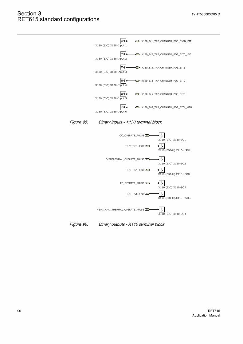
X130_BI2_TAP_CHANGER_POS_BIT0_LSB
X130_BI3_TAP_CHANGER_POS_BIT1
X130_BI4_TAP_CHANGER_POS_BIT2
X130_BI5_TAP_CHANGER_POS_BIT3
X130_BI6_TAP_CHANGER_POS_BIT4_MSB
X130_BI1_TAP_CHANGER_POS_SIGN_BIT
X130 (BIO).X130-Input 1
X130 (BIO).X130-Input 2
X130 (BIO).X130-Input 3
X130 (BIO).X130-Input 4
X130 (BIO).X130-Input 5
X130 (BIO).X130-Input 6GUID-C2DF1008-30C4-4E22-9A63-0E62A5829485 V1 EN
Figure 95: Binary inputs - X130 terminal block
OC_OPERATE_PULSE
DIFFERENTIAL_OPERATE_PULSE
EF_OPERATE_PULSE
NSOC_AND_THERMAL_OPERATE_PULSE
TRPPTRC3_TRIP
TRPPTRC4_TRIP
TRPPTRC5_TRIP
X110 (BIO).X110-SO1
X110 (BIO).X110-SO2
X110 (BIO).X110-SO4
X110 (BIO).X110-SO3
X110 (BIO-H).X110-HSO1
X110 (BIO-H).X110-HSO2
X110 (BIO-H).X110-HSO3
GUID-54F094C9-6D2D-4F68-82DD-D1491036C218 V1 EN
Figure 96: Binary outputs - X110 terminal block
Section 3 1YHT530003D05 DRET615 standard configurations
90 RET615Application Manual
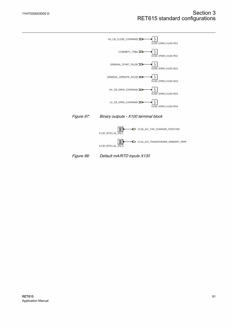
HV_CB_CLOSE_COMMAND
HV_CB_OPEN_COMMAND
GENERAL_START_PULSE
GENERAL_OPERATE_PULSE
LV_CB_OPEN_COMMAND
CCBRBRF1_TRBU
X100 (PSM).X100-PO1
X100 (PSM).X100-PO2
X100 (PSM).X100-SO1
X100 (PSM).X100-SO2
X100 (PSM).X100-PO3
X100 (PSM).X100-PO4GUID-9A5D9E9E-FD88-4925-B143-473069A991B0 V1 EN
Figure 97: Binary outputs - X100 terminal block
X130_AI1_TAP_CHANGER_POSITION
X130 (RTD).AI_VAL1
X130_AI3_TRANSFORMER_AMBIENT_TEMP
X130 (RTD).AI_VAL3GUID-BE9420CD-A414-4A5C-AF91-38642D0D54EC V1 EN
Figure 98: Default mA/RTD inputs X130
1YHT530003D05 D Section 3RET615 standard configurations
RET615 91Application Manual
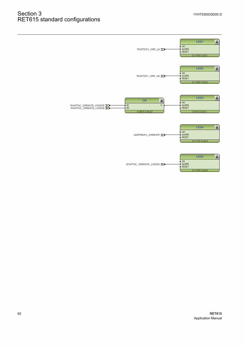
LED1
O:115|T:2.5|I:1
OKALARMRESET
LED2
O:118|T:2.5|I:2
OKALARMRESET
LED3
O:91|T:2.5|I:3
OKALARMRESET
LED4
O:111|T:2.5|I:4
OKALARMRESET
LED5
O:114|T:2.5|I:5
OKALARMRESET
OR
O:90|T:2.5|I:22
B1B2
O
LREFPNDF1_OPERATE
EFxPTOC_OPERATE_LVSIDE
PHxPTOC_OPERATE_HVSIDEPHxPTOC_OPERATE_LVSIDE
TR2PTDF1_OPR_LS
TR2PTDF1_OPR_HS
GUID-344F05C2-4919-4D0F-A208-EDEEFA47EB66 V1 EN
Section 3 1YHT530003D05 DRET615 standard configurations
92 RET615Application Manual
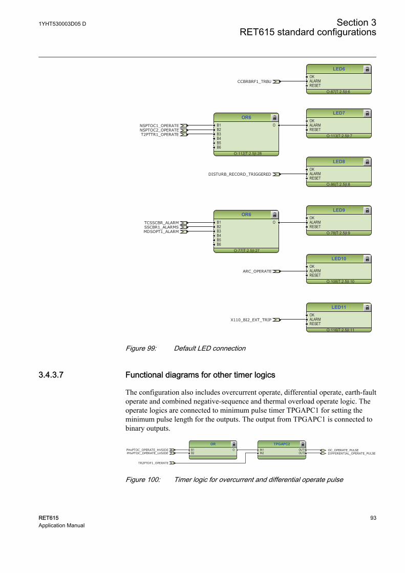
LED6
O:87|T:2.5|I:6
OKALARMRESET
LED7
O:113|T:2.5|I:7
OKALARMRESET
LED8
O:86|T:2.5|I:8
OKALARMRESET
LED9
O:78|T:2.5|I:9
OKALARMRESET
LED10
O:108|T:2.5|I:10
OKALARMRESET
LED11
O:116|T:2.5|I:11
OKALARMRESET
OR6
O:77|T:2.5|I:27
B1B2B3B4B5B6
O
OR6
O:112|T:2.5|I:28
B1B2B3B4B5B6
O
CCBRBRF1_TRBU
NSPTOC1_OPERATE
X110_BI2_EXT_TRIP
T2PTTR1_OPERATENSPTOC2_OPERATE
MDSOPT1_ALARM
ARC_OPERATE
TCSSCBR_ALARMSSCBR1_ALARMS
DISTURB_RECORD_TRIGGERED
GUID-C7BFA5F1-20AB-47D2-97CC-6911BD83A808 V1 EN
Figure 99: Default LED connection
3.4.3.7 Functional diagrams for other timer logics
The configuration also includes overcurrent operate, differential operate, earth-faultoperate and combined negative-sequence and thermal overload operate logic. Theoperate logics are connected to minimum pulse timer TPGAPC1 for setting theminimum pulse length for the outputs. The output from TPGAPC1 is connected tobinary outputs.
TPGAPC2IN1IN2
OUT1OUT2
ORB1B2
O OC_OPERATE_PULSEDIFFERENTIAL_OPERATE_PULSE
TR2PTDF1_OPERATE
PHxPTOC_OPERATE_HVSIDEPHxPTOC_OPERATE_LVSIDE
GUID-7419E0FC-CB2A-4FC7-8CF8-EAD89F3467E9 V1 EN
Figure 100: Timer logic for overcurrent and differential operate pulse
1YHT530003D05 D Section 3RET615 standard configurations
RET615 93Application Manual
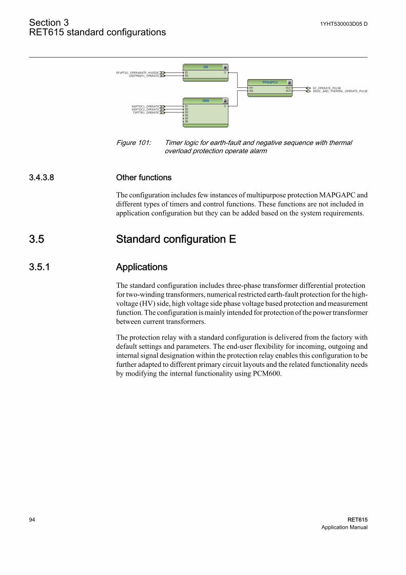
TPGAPC3IN1IN2
OUT1OUT2
OR6B1B2B3B4B5B6
O
ORB1B2
O
EF_OPERATE_PULSENSOC_AND_THERMAL_OPERATE_PULSE
LREFPNDF1_OPERATE
NSPTOC1_OPERATE
T2PTTR1_OPERATENSPTOC2_OPERATE
EFxPTOC_OPERARATE_HVSIDE
GUID-3FB48296-45BC-46F0-A339-3358781DDBC1 V1 EN
Figure 101: Timer logic for earth-fault and negative sequence with thermaloverload protection operate alarm
3.4.3.8 Other functions
The configuration includes few instances of multipurpose protection MAPGAPC anddifferent types of timers and control functions. These functions are not included inapplication configuration but they can be added based on the system requirements.
3.5 Standard configuration E
3.5.1 Applications
The standard configuration includes three-phase transformer differential protectionfor two-winding transformers, numerical restricted earth-fault protection for the high-voltage (HV) side, high voltage side phase voltage based protection and measurementfunction. The configuration is mainly intended for protection of the power transformerbetween current transformers.
The protection relay with a standard configuration is delivered from the factory withdefault settings and parameters. The end-user flexibility for incoming, outgoing andinternal signal designation within the protection relay enables this configuration to befurther adapted to different primary circuit layouts and the related functionality needsby modifying the internal functionality using PCM600.
Section 3 1YHT530003D05 DRET615 standard configurations
94 RET615Application Manual
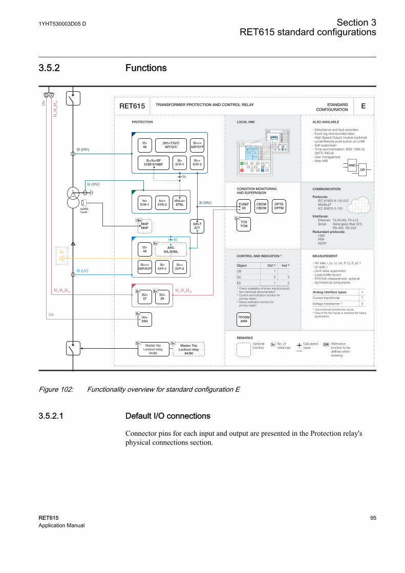
3.5.2 Functions
Master tripLockout relay
94/86
2xRTD1xmA
CONDITION MONITORING AND SUPERVISION
ALSO AVAILABLE
- Disturbance and fault recorders- Event log and recorded data- High-Speed Output module (optional)- Local/Remote push button on LHMI- Self-supervision- Time synchronization: IEEE 1588 v2,
SNTP, IRIG-B- User management- Web HMI
ORAND
CONTROL AND INDICATION 1) MEASUREMENT
TRANSFORMER PROTECTION AND CONTROL RELAY
PROTECTION LOCAL HMI
Object Ctrl 2) Ind 3)
CB
DC
ES1) Check availability of binary inputs/outputs
from technical documentation2) Control and indication function for
primary object3) Status indication function for primary object
1 -
2 3
1 2
STANDARD CONFIGURATION
REMARKS
Optionalfunction
No. ofinstances
Alternative function to be defined when ordering
OR
Io/Uo
Calculatedvalue
3×
RL
ClearESCI
O
Configuration ASystemHMITimeAuthorization
RL
ClearESCI
O
U12 0. 0 kVP 0.00 kWQ 0.00 kVAr
IL2 0 A
A
COMMUNICATION
Protocols: IEC 61850-8-1/9-2LE Modbus®
IEC 60870-5-103 Interfaces: Ethernet: TX (RJ45), FX (LC) Serial: Serial glass fiber (ST), RS-485, RS-232Redundant protocols: HSR PRP RSTP
RET615 E
7
5
Analog interface types 1)
Current transformer
1) Conventional transformer inputs
Voltage transformer 2)
2) One of the five inputs is reserved for future applications
- HV side: I, Io, U, Uo, P, Q, E, pf, f- LV side: I- Limit value supervision- Load profile record- RTD/mA measurement, optional- Symmetrical components
3Ith>T/G/C49T/G/C
I2>46
3I>>>50P/51P
3I>/Io>BF51BF/51NBF
3I>51P-1
3I>>51P-2
3dI>T87T
I2>46
3×ARC
50L/50NL
2×TCSTCM
CBCMCBCM
OPTSOPTM
3I>>51P-2
3I>>>50P/51P
3I>51P-1
Io>51N-1
Io>>51N-2
dIoLo>87NL
2×3U<27
2×Uo>59G
FUSEF60
18×MAPMAP
3I (LV)
2×3U>59
UL1
UL2
UL3
UL1UL2UL3
Uo
Uo
Io
Io
Io (HV)
UL1UL2UL3
TPOSM84M
3×
3I (HV)
3I (HV)
Master TripLockout relay
94/86
3×2×
GUID-79894D86-1B47-453A-BF77-22570C9AC30D V1 EN
Figure 102: Functionality overview for standard configuration E
3.5.2.1 Default I/O connections
Connector pins for each input and output are presented in the Protection relay'sphysical connections section.
1YHT530003D05 D Section 3RET615 standard configurations
RET615 95Application Manual
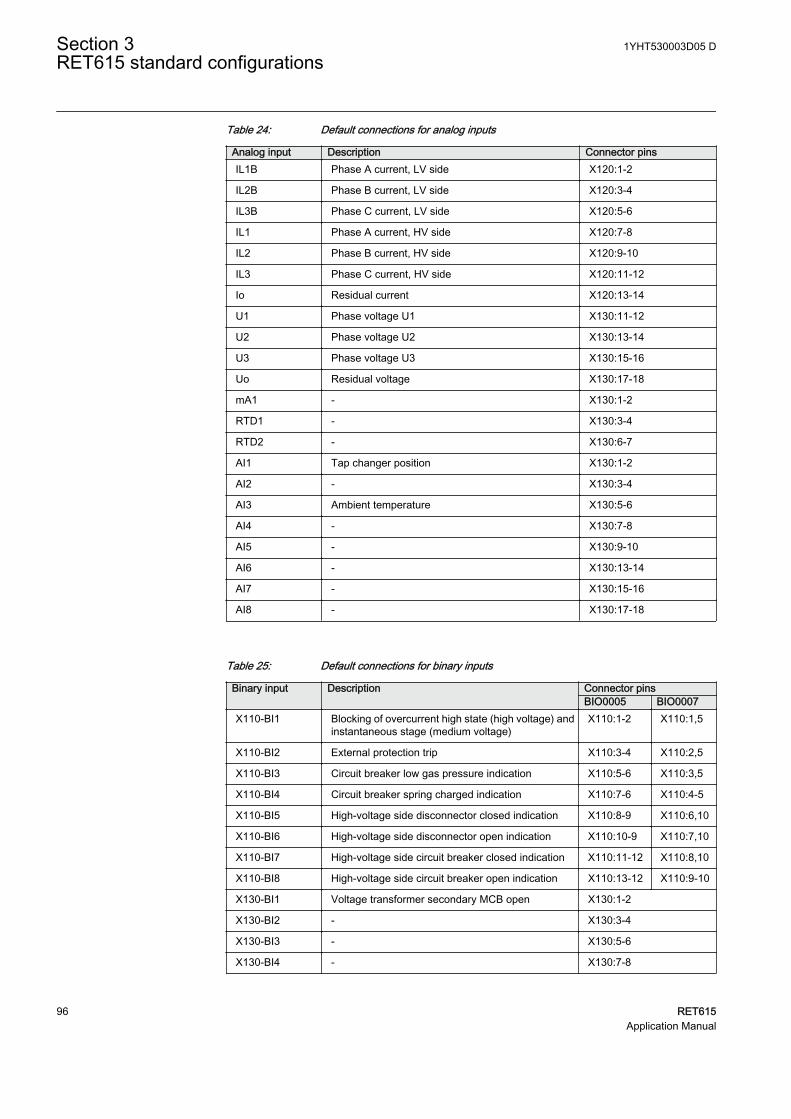
Table 24: Default connections for analog inputs
Analog input Description Connector pinsIL1B Phase A current, LV side X120:1-2
IL2B Phase B current, LV side X120:3-4
IL3B Phase C current, LV side X120:5-6
IL1 Phase A current, HV side X120:7-8
IL2 Phase B current, HV side X120:9-10
IL3 Phase C current, HV side X120:11-12
Io Residual current X120:13-14
U1 Phase voltage U1 X130:11-12
U2 Phase voltage U2 X130:13-14
U3 Phase voltage U3 X130:15-16
Uo Residual voltage X130:17-18
mA1 - X130:1-2
RTD1 - X130:3-4
RTD2 - X130:6-7
AI1 Tap changer position X130:1-2
AI2 - X130:3-4
AI3 Ambient temperature X130:5-6
AI4 - X130:7-8
AI5 - X130:9-10
AI6 - X130:13-14
AI7 - X130:15-16
AI8 - X130:17-18
Table 25: Default connections for binary inputs
Binary input Description Connector pinsBIO0005 BIO0007
X110-BI1 Blocking of overcurrent high state (high voltage) andinstantaneous stage (medium voltage)
X110:1-2 X110:1,5
X110-BI2 External protection trip X110:3-4 X110:2,5
X110-BI3 Circuit breaker low gas pressure indication X110:5-6 X110:3,5
X110-BI4 Circuit breaker spring charged indication X110:7-6 X110:4-5
X110-BI5 High-voltage side disconnector closed indication X110:8-9 X110:6,10
X110-BI6 High-voltage side disconnector open indication X110:10-9 X110:7,10
X110-BI7 High-voltage side circuit breaker closed indication X110:11-12 X110:8,10
X110-BI8 High-voltage side circuit breaker open indication X110:13-12 X110:9-10
X130-BI1 Voltage transformer secondary MCB open X130:1-2
X130-BI2 - X130:3-4
X130-BI3 - X130:5-6
X130-BI4 - X130:7-8
Section 3 1YHT530003D05 DRET615 standard configurations
96 RET615Application Manual
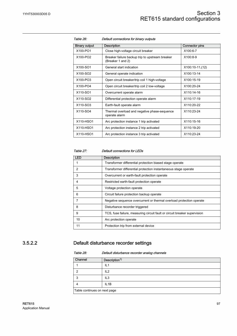
Table 26: Default connections for binary outputs
Binary output Description Connector pinsX100-PO1 Close high-voltage circuit breaker X100:6-7
X100-PO2 Breaker failure backup trip to upstream breaker(Breaker 1 and 2)
X100:8-9
X100-SO1 General start indication X100:10-11,(12)
X100-SO2 General operate indication X100:13-14
X100-PO3 Open circuit breaker/trip coil 1 high-voltage X100:15-19
X100-PO4 Open circuit breaker/trip coil 2 low-voltage X100:20-24
X110-SO1 Overcurrent operate alarm X110:14-16
X110-SO2 Differential protection operate alarm X110:17-19
X110-SO3 Earth-fault operate alarm X110:20-22
X110-SO4 Thermal overload and negative phase-sequenceoperate alarm
X110:23-24
X110-HSO1 Arc protection instance 1 trip activated X110:15-16
X110-HSO1 Arc protection instance 2 trip activated X110:19-20
X110-HSO1 Arc protection instance 3 trip activated X110:23-24
Table 27: Default connections for LEDs
LED Description1 Transformer differential protection biased stage operate
2 Transformer differential protection instantaneous stage operate
3 Overcurrent or earth-fault protection operate
4 Restricted earth-fault protection operate
5 Voltage protection operate
6 Circuit failure protection backup operate
7 Negative sequence overcurrent or thermal overload protection operate
8 Disturbance recorder triggered
9 TCS, fuse failure, measuring circuit fault or circuit breaker supervision
10 Arc protection operate
11 Protection trip from external device
3.5.2.2 Default disturbance recorder settings
Table 28: Default disturbance recorder analog channels
Channel Description1)
1 IL1
2 IL2
3 IL3
4 IL1B
Table continues on next page
1YHT530003D05 D Section 3RET615 standard configurations
RET615 97Application Manual

Channel Description1)
5 IL2B
6 IL3B
7 Io
8Uo Uo
9 U1
10 U2
11 U3
12 -
1) Text with “B” refers to measurement on low-voltage side of the transformer
Table 29: Default disturbance recorder binary channels
Channel ID text Level trigger mode1 PHIPTOC1 - start Positive or Rising
2 PHHPTOC1 - start Positive or Rising
3 PHLPTOC1 - start Positive or Rising
4 PHIPTOC2 - start Positive or Rising
5 PHHPTOC2 - start Positive or Rising
6 PHLPTOC2 - start Positive or Rising
7 EFHPTOC2 - start Positive or Rising
8 EFLPTOC2 - start Positive or Rising
9 NSPTOC1 - start Positive or Rising
10 NSPTOC2 - start Positive or Rising
11 LREFPNDF1 - start Positive or Rising
12 T2PTTR1 - start Positive or Rising
13 ROVPTOV1 - start Positive or Rising
14 ROVPTOV2 - start Positive or Rising
15 PHPTOV1 - start Positive or Rising
16 PHPTOV2 - start Positive or Rising
17 PHPTUV1 - start Positive or Rising
18 PHPTUV2 - start Positive or Rising
19 CCBRBRF1 - trret Level trigger off
20 CCBRBRF1 - trbu Level trigger off
21 PHIPTOC1 - operate Level trigger off
PHHPTOC1 - operate
PHLPTOC1 - operate
22 PHIPTOC2 - operate Level trigger off
PHHPTOC2- operate
PHLPTOC2 - operate
Table continues on next page
Section 3 1YHT530003D05 DRET615 standard configurations
98 RET615Application Manual
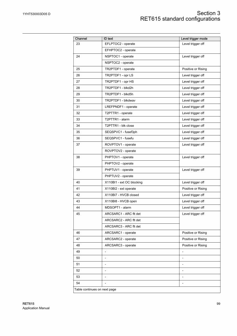
Channel ID text Level trigger mode23 EFLPTOC2 - operate Level trigger off
EFHPTOC2 - operate
24 NSPTOC1 - operate Level trigger off
NSPTOC2 - operate
25 TR2PTDF1 - operate Positive or Rising
26 TR2PTDF1 - opr LS Level trigger off
27 TR2PTDF1 - opr HS Level trigger off
28 TR2PTDF1 - blkd2h Level trigger off
29 TR2PTDF1 - blkd5h Level trigger off
30 TR2PTDF1 - blkdwav Level trigger off
31 LREFPNDF1 - operate Level trigger off
32 T2PTTR1 - operate Level trigger off
33 T2PTTR1 - alarm Level trigger off
34 T2PTTR1 - blk close Level trigger off
35 SEQSPVC1 - fusef3ph Level trigger off
36 SEQSPVC1 - fusefu Level trigger off
37 ROVPTOV1 - operate Level trigger off
ROVPTOV2 - operate
38 PHPTOV1 - operate Level trigger off
PHPTOV2 - operate
39 PHPTUV1 - operate Level trigger off
PHPTUV2 - operate
40 X110BI1 - ext OC blocking Level trigger off
41 X110BI2 - ext operate Positive or Rising
42 X110BI7 - HVCB closed Level trigger off
43 X110BI8 - HVCB open Level trigger off
44 MDSOPT1 - alarm Level trigger off
45 ARCSARC1 - ARC flt det Level trigger off
ARCSARC2 - ARC flt det
ARCSARC3 - ARC flt det
46 ARCSARC1 - operate Positive or Rising
47 ARCSARC2 - operate Positive or Rising
48 ARCSARC3 - operate Positive or Rising
49 - -
50 - -
51 - -
52 - -
53 - -
54 - -
Table continues on next page
1YHT530003D05 D Section 3RET615 standard configurations
RET615 99Application Manual
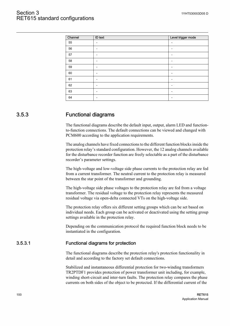
Channel ID text Level trigger mode55 - -
56 - -
57 - -
58 - -
59 - -
60 - -
61 - -
62 - -
63 - -
64 - -
3.5.3 Functional diagrams
The functional diagrams describe the default input, output, alarm LED and function-to-function connections. The default connections can be viewed and changed withPCM600 according to the application requirements.
The analog channels have fixed connections to the different function blocks inside theprotection relay’s standard configuration. However, the 12 analog channels availablefor the disturbance recorder function are freely selectable as a part of the disturbancerecorder’s parameter settings.
The high-voltage and low-voltage side phase currents to the protection relay are fedfrom a current transformer. The neutral current to the protection relay is measuredbetween the star point of the transformer and grounding.
The high-voltage side phase voltages to the protection relay are fed from a voltagetransformer. The residual voltage to the protection relay represents the measuredresidual voltage via open-delta connected VTs on the high-voltage side.
The protection relay offers six different setting groups which can be set based onindividual needs. Each group can be activated or deactivated using the setting groupsettings available in the protection relay.
Depending on the communication protocol the required function block needs to beinstantiated in the configuration.
3.5.3.1 Functional diagrams for protection
The functional diagrams describe the protection relay's protection functionality indetail and according to the factory set default connections.
Stabilized and instantaneous differential protection for two-winding transformersTR2PTDF1 provides protection of power transformer unit including, for example,winding short-circuit and inter-turn faults. The protection relay compares the phasecurrents on both sides of the object to be protected. If the differential current of the
Section 3 1YHT530003D05 DRET615 standard configurations
100 RET615Application Manual

phase currents in one of the phases exceeds the setting of the stabilized operationcharacteristic or the instantaneous protection stage of the function, the functionprovides an operate signal. All operate signals from the functions are connected to themaster trips as well as to alarm LEDs
For transformers having an online tap changer, the tap position information isrecommended to be used in differential protection, as the ratio difference of tapchanger movements can be corrected in TR2PTDF1.
TR2PTDF1BLOCKBLK_OPR_LSBLK_OPR_HS
OPERATEOPR_LSOPR_HSBLKD2HBLKD5H
BLKDWAV
TR2PTDF1_OPERATETR2PTDF1_OPR_LSTR2PTDF1_OPR_HSTR2PTDF1_BLKD2HTR2PTDF1_BLKD5HTR2PTDF1_BLKDWAV
GUID-44121A71-79F7-4CD0-A099-180EA4BFDCAA V1 EN
Figure 103: Transformer differential protection function
Three non-directional overcurrent stages each are offered for overcurrent and short-circuit protection for high-voltage as well as low-voltage side of the transformer. Thehigh stage of high-voltage side PHHPTOC1 and instantaneous stage of low-voltageside PHIPTOC2 can be blocked by energizing the binary input X110:BI1. In addition,high stage of high-voltage side PHHPTOC1 is blocked by start of high stage of low-voltage side PHHPTOC2.
A selective backup overcurrent protection can be achieved by using blockingsbetween high-voltage side and low-voltage side overcurrent stages. This kind ofblocking scheme enables coordinated overlapping of overcurrent protection zones.
PHIPTOC1BLOCKENA_MULT
OPERATESTART
PHLPTOC1BLOCKENA_MULT
OPERATESTART
PHHPTOC1BLOCKENA_MULT
OPERATESTART
ORB1B2
O
OR6B1B2B3B4B5B6
O
PHIPTOC1_OPERATE
PHIPTOC1_OPERATE
PHLPTOC1_OPERATE
PHLPTOC1_OPERATE
PHHPTOC1_OPERATE
PHHPTOC1_OPERATE
PHIPTOC1_START
PHLPTOC1_START
PHHPTOC1_STARTPHHPTOC2_START
X110_BI1_EXT_OC_BLOCKING
PHxPTOC_OPERATE_HVSIDE
GUID-05D4D163-817C-45E6-A646-07C61F9A5C09 V1 EN
Figure 104: High-voltage side overcurrent protection function
1YHT530003D05 D Section 3RET615 standard configurations
RET615 101Application Manual
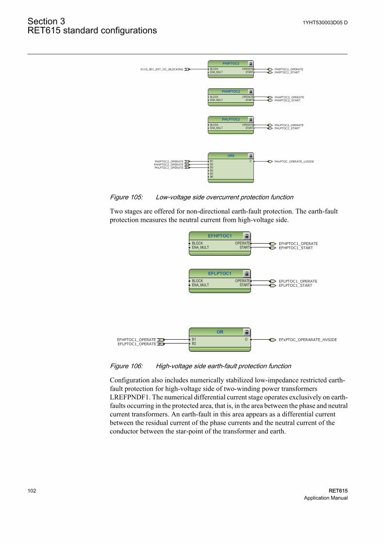
PHIPTOC2BLOCKENA_MULT
OPERATESTART
PHHPTOC2BLOCKENA_MULT
OPERATESTART
PHLPTOC2BLOCKENA_MULT
OPERATESTART
OR6B1B2B3B4B5B6
O
PHIPTOC2_OPERATE
PHIPTOC2_OPERATE
PHLPTOC2_OPERATE
PHLPTOC2_OPERATE
PHHPTOC2_OPERATE
PHHPTOC2_OPERATE
PHLPTOC2_START
PHIPTOC2_START
PHHPTOC2_START
X110_BI1_EXT_OC_BLOCKING
PHxPTOC_OPERATE_LVSIDE
GUID-E0620F10-1603-4271-A719-F04A27775D63 V1 EN
Figure 105: Low-voltage side overcurrent protection function
Two stages are offered for non-directional earth-fault protection. The earth-faultprotection measures the neutral current from high-voltage side.
EFHPTOC1BLOCKENA_MULT
OPERATESTART
EFLPTOC1BLOCKENA_MULT
OPERATESTART
ORB1B2
O
EFHPTOC1_OPERATE
EFHPTOC1_OPERATE
EFLPTOC1_OPERATE
EFLPTOC1_OPERATE
EFHPTOC1_START
EFLPTOC1_START
EFxPTOC_OPERARATE_HVSIDE
GUID-F1376F17-4B3C-40D3-8DAC-58A3A4B3B07E V1 EN
Figure 106: High-voltage side earth-fault protection function
Configuration also includes numerically stabilized low-impedance restricted earth-fault protection for high-voltage side of two-winding power transformersLREFPNDF1. The numerical differential current stage operates exclusively on earth-faults occurring in the protected area, that is, in the area between the phase and neutralcurrent transformers. An earth-fault in this area appears as a differential currentbetween the residual current of the phase currents and the neutral current of theconductor between the star-point of the transformer and earth.
Section 3 1YHT530003D05 DRET615 standard configurations
102 RET615Application Manual
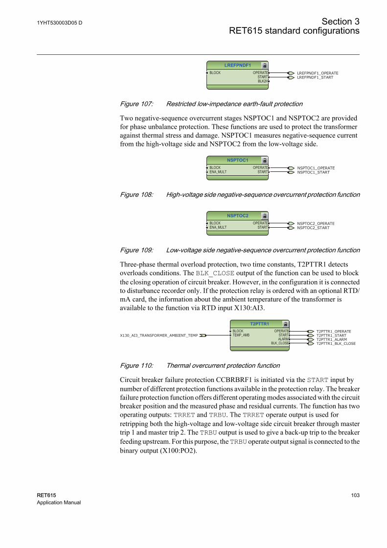
LREFPNDF1BLOCK OPERATE
STARTBLK2H
LREFPNDF1_OPERATELREFPNDF1_START
GUID-421C3801-D022-4A12-B11A-07FF72F53530 V1 EN
Figure 107: Restricted low-impedance earth-fault protection
Two negative-sequence overcurrent stages NSPTOC1 and NSPTOC2 are providedfor phase unbalance protection. These functions are used to protect the transformeragainst thermal stress and damage. NSPTOC1 measures negative-sequence currentfrom the high-voltage side and NSPTOC2 from the low-voltage side.
NSPTOC1BLOCKENA_MULT
OPERATESTART
NSPTOC1_OPERATENSPTOC1_START
GUID-A2C16F14-559F-450A-A4CA-820166E4651A V1 EN
Figure 108: High-voltage side negative-sequence overcurrent protection function
NSPTOC2BLOCKENA_MULT
OPERATESTART
NSPTOC2_OPERATENSPTOC2_START
GUID-DAC107C0-C371-4763-971B-7C67F30FC7BB V1 EN
Figure 109: Low-voltage side negative-sequence overcurrent protection function
Three-phase thermal overload protection, two time constants, T2PTTR1 detectsoverloads conditions. The BLK_CLOSE output of the function can be used to blockthe closing operation of circuit breaker. However, in the configuration it is connectedto disturbance recorder only. If the protection relay is ordered with an optional RTD/mA card, the information about the ambient temperature of the transformer isavailable to the function via RTD input X130:AI3.
T2PTTR1BLOCKTEMP_AMB
OPERATESTARTALARM
BLK_CLOSE
T2PTTR1_OPERATET2PTTR1_STARTX130_AI3_TRANSFORMER_AMBIENT_TEMPT2PTTR1_ALARMT2PTTR1_BLK_CLOSE
GUID-1E47C845-F289-4A8D-BC74-AF06AD5818A5 V1 EN
Figure 110: Thermal overcurrent protection function
Circuit breaker failure protection CCBRBRF1 is initiated via the START input bynumber of different protection functions available in the protection relay. The breakerfailure protection function offers different operating modes associated with the circuitbreaker position and the measured phase and residual currents. The function has twooperating outputs: TRRET and TRBU. The TRRET operate output is used forretripping both the high-voltage and low-voltage side circuit breaker through mastertrip 1 and master trip 2. The TRBU output is used to give a back-up trip to the breakerfeeding upstream. For this purpose, the TRBU operate output signal is connected to thebinary output (X100:PO2).
1YHT530003D05 D Section 3RET615 standard configurations
RET615 103Application Manual
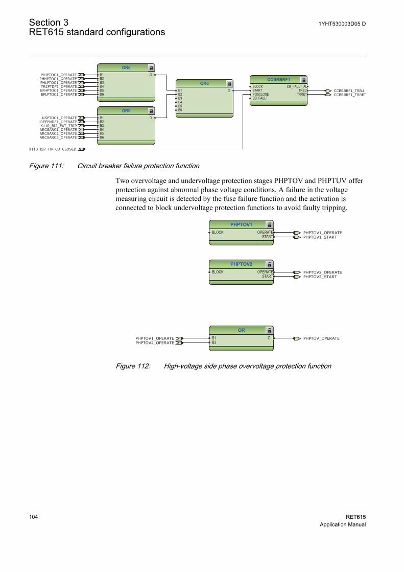
CCBRBRF1BLOCKSTARTPOSCLOSECB_FAULT
CB_FAULT_ALTRBU
TRRET
OR6B1B2B3B4B5B6
O
OR6B1B2B3B4B5B6
O
OR6B1B2B3B4B5B6
O CCBRBRF1_TRBU
X110_BI7_HV_CB_CLOSED
PHIPTOC1_OPERATE
PHLPTOC1_OPERATEPHHPTOC1_OPERATE
LREFPNDF1_OPERATE
CCBRBRF1_TRRET
NSPTOC1_OPERATE
TR2PTDF1_OPERATE
X110_BI2_EXT_TRIPARCSARC1_OPERATEARCSARC2_OPERATEARCSARC3_OPERATE
EFHPTOC1_OPERATEEFLPTOC1_OPERATE
GUID-CCFC552B-D706-47E5-BB1D-06E840518F63 V1 EN
Figure 111: Circuit breaker failure protection function
Two overvoltage and undervoltage protection stages PHPTOV and PHPTUV offerprotection against abnormal phase voltage conditions. A failure in the voltagemeasuring circuit is detected by the fuse failure function and the activation isconnected to block undervoltage protection functions to avoid faulty tripping.
PHPTOV1BLOCK OPERATE
START
PHPTOV2BLOCK OPERATE
START
ORB1B2
O
PHPTOV1_OPERATE
PHPTOV1_OPERATE
PHPTOV2_OPERATE
PHPTOV2_OPERATE
PHPTOV1_START
PHPTOV2_START
PHPTOV_OPERATE
GUID-9ACA3E71-4883-41BA-9830-1CB80BDD194C V1 EN
Figure 112: High-voltage side phase overvoltage protection function
Section 3 1YHT530003D05 DRET615 standard configurations
104 RET615Application Manual
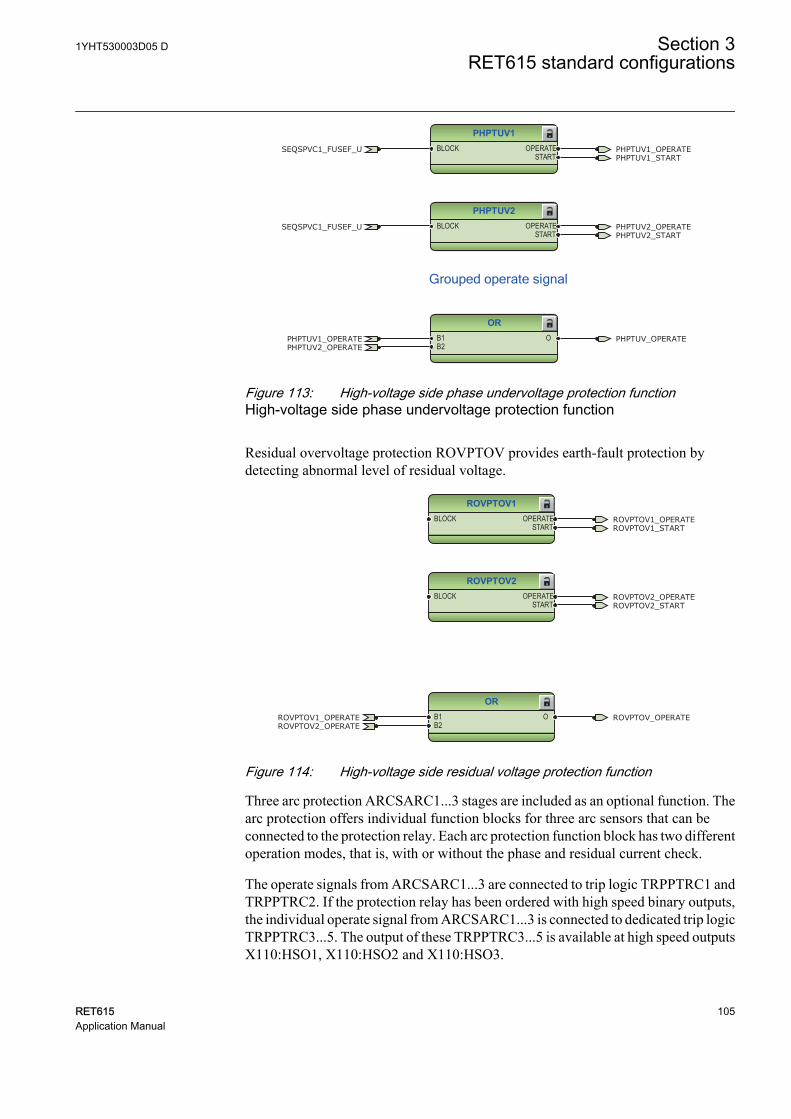
PHPTUV1BLOCK OPERATE
START
PHPTUV2BLOCK OPERATE
START
ORB1B2
O
PHPTUV1_OPERATE
PHPTUV1_OPERATE
PHPTUV2_OPERATE
PHPTUV2_OPERATE
PHPTUV1_START
PHPTUV2_START
SEQSPVC1_FUSEF_U
SEQSPVC1_FUSEF_U
PHPTUV_OPERATE
Grouped operate signal
GUID-5AEC4B27-C17B-4BEE-BC50-5E98385F0B68 V2 EN
Figure 113: High-voltage side phase undervoltage protection functionHigh-voltage side phase undervoltage protection function
Residual overvoltage protection ROVPTOV provides earth-fault protection bydetecting abnormal level of residual voltage.
ROVPTOV1BLOCK OPERATE
START
ROVPTOV2BLOCK OPERATE
START
ORB1B2
O
ROVPTOV1_OPERATE
ROVPTOV1_OPERATE
ROVPTOV2_OPERATE
ROVPTOV2_OPERATE
ROVPTOV1_START
ROVPTOV2_START
ROVPTOV_OPERATE
GUID-AF2C7A6C-469C-4B8A-9294-83726E48A16A V1 EN
Figure 114: High-voltage side residual voltage protection function
Three arc protection ARCSARC1...3 stages are included as an optional function. Thearc protection offers individual function blocks for three arc sensors that can beconnected to the protection relay. Each arc protection function block has two differentoperation modes, that is, with or without the phase and residual current check.
The operate signals from ARCSARC1...3 are connected to trip logic TRPPTRC1 andTRPPTRC2. If the protection relay has been ordered with high speed binary outputs,the individual operate signal from ARCSARC1...3 is connected to dedicated trip logicTRPPTRC3...5. The output of these TRPPTRC3...5 is available at high speed outputsX110:HSO1, X110:HSO2 and X110:HSO3.
1YHT530003D05 D Section 3RET615 standard configurations
RET615 105Application Manual
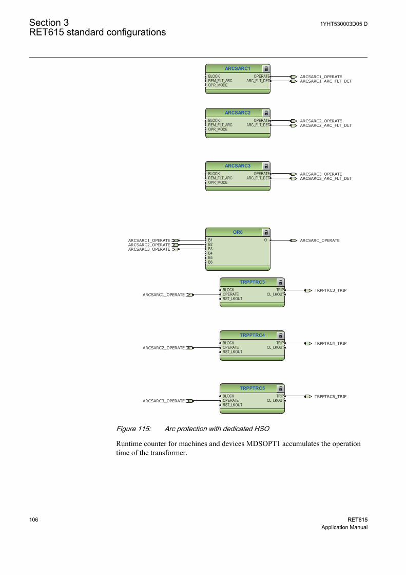
ARCSARC1BLOCKREM_FLT_ARCOPR_MODE
OPERATEARC_FLT_DET
ARCSARC2BLOCKREM_FLT_ARCOPR_MODE
OPERATEARC_FLT_DET
ARCSARC3BLOCKREM_FLT_ARCOPR_MODE
OPERATEARC_FLT_DET
OR6B1B2B3B4B5B6
O
ARCSARC1_OPERATE
ARCSARC1_OPERATE
ARCSARC2_OPERATE
ARCSARC2_OPERATE
ARCSARC3_OPERATE
ARCSARC3_OPERATE
ARCSARC1_ARC_FLT_DET
ARCSARC2_ARC_FLT_DET
ARCSARC3_ARC_FLT_DET
ARCSARC_OPERATE
GUID-EF80C7D9-0E08-404D-8E22-0E7799DF7140 V1 EN
TRPPTRC3BLOCKOPERATERST_LKOUT
TRIPCL_LKOUT
TRPPTRC4BLOCKOPERATERST_LKOUT
TRIPCL_LKOUT
TRPPTRC5BLOCKOPERATERST_LKOUT
TRIPCL_LKOUT
TRPPTRC3_TRIP
TRPPTRC4_TRIP
TRPPTRC5_TRIP
ARCSARC1_OPERATE
ARCSARC2_OPERATE
ARCSARC3_OPERATE
GUID-01483773-9024-41D5-AD57-EBDD986D08EF V1 EN
Figure 115: Arc protection with dedicated HSO
Runtime counter for machines and devices MDSOPT1 accumulates the operationtime of the transformer.
Section 3 1YHT530003D05 DRET615 standard configurations
106 RET615Application Manual
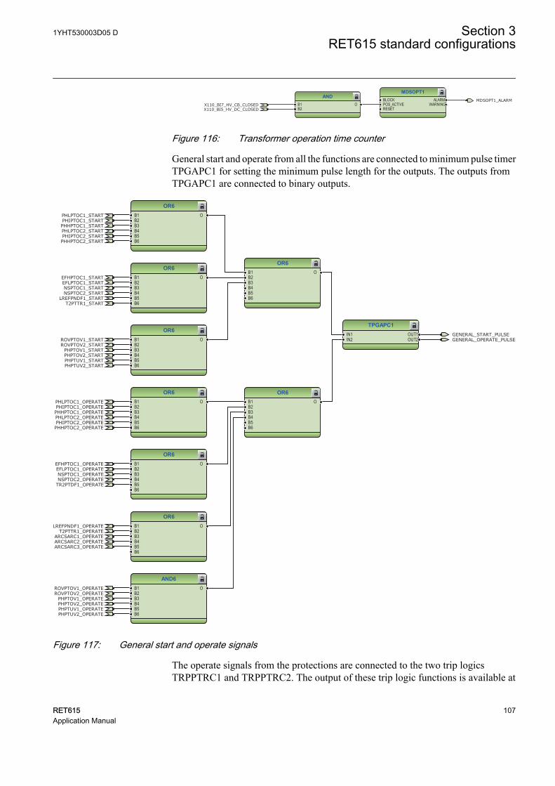
MDSOPT1BLOCKPOS_ACTIVERESET
ALARMWARNING
ANDB1B2
OX110_BI7_HV_CB_CLOSEDX110_BI5_HV_DC_CLOSED
MDSOPT1_ALARM
GUID-F791744D-1968-49AE-ABF4-E02A4DBA12E9 V1 EN
Figure 116: Transformer operation time counter
General start and operate from all the functions are connected to minimum pulse timerTPGAPC1 for setting the minimum pulse length for the outputs. The outputs fromTPGAPC1 are connected to binary outputs.
OR6B1B2B3B4B5B6
O
OR6B1B2B3B4B5B6
O
OR6B1B2B3B4B5B6
O
OR6B1B2B3B4B5B6
O
OR6B1B2B3B4B5B6
O
OR6B1B2B3B4B5B6
O
OR6B1B2B3B4B5B6
O
OR6B1B2B3B4B5B6
O
TPGAPC1IN1IN2
OUT1OUT2
AND6B1B2B3B4B5B6
O
GENERAL_START_PULSEGENERAL_OPERATE_PULSE
PHIPTOC1_OPERATEPHLPTOC1_OPERATE
PHHPTOC1_OPERATE
LREFPNDF1_OPERATE
NSPTOC1_OPERATE
TR2PTDF1_OPERATE
ARCSARC1_OPERATEARCSARC2_OPERATEARCSARC3_OPERATE
EFHPTOC1_OPERATEEFLPTOC1_OPERATE
ROVPTOV1_OPERATEROVPTOV2_OPERATE
PHPTOV1_OPERATEPHPTOV2_OPERATEPHPTUV1_OPERATEPHPTUV2_OPERATE
PHIPTOC2_OPERATEPHLPTOC2_OPERATE
PHHPTOC2_OPERATE
T2PTTR1_OPERATE
NSPTOC2_OPERATE
PHIPTOC1_STARTPHLPTOC1_START
PHHPTOC1_STARTPHLPTOC2_STARTPHIPTOC2_STARTPHHPTOC2_START
EFHPTOC1_STARTEFLPTOC1_STARTNSPTOC1_STARTNSPTOC2_START
LREFPNDF1_STARTT2PTTR1_START
ROVPTOV1_STARTROVPTOV2_START
PHPTOV1_STARTPHPTOV2_STARTPHPTUV1_STARTPHPTUV2_START
GUID-D3B11893-6797-439E-A630-9BC09228BDB2 V1 EN
Figure 117: General start and operate signals
The operate signals from the protections are connected to the two trip logicsTRPPTRC1 and TRPPTRC2. The output of these trip logic functions is available at
1YHT530003D05 D Section 3RET615 standard configurations
RET615 107Application Manual
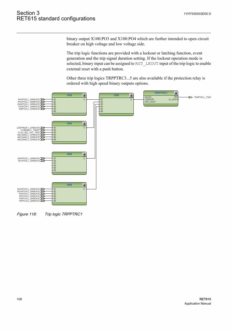
binary output X100:PO3 and X100:PO4 which are further intended to open circuitbreaker on high voltage and low voltage side.
The trip logic functions are provided with a lockout or latching function, eventgeneration and the trip signal duration setting. If the lockout operation mode isselected, binary input can be assigned to RST_LKOUT input of the trip logic to enableexternal reset with a push button.
Other three trip logics TRPPTRC3...5 are also available if the protection relay isordered with high speed binary outputs options.
TRPPTRC1BLOCKOPERATERST_LKOUT
TRIPCL_LKOUT
OR6B1B2B3B4B5B6
O
OR6B1B2B3B4B5B6
O
OR6B1B2B3B4B5B6
O
OR6B1B2B3B4B5B6
O
OR6B1B2B3B4B5B6
O
TRPPTRC1_TRIPPHIPTOC1_OPERATEPHLPTOC1_OPERATEPHHPTOC1_OPERATE
LREFPNDF1_OPERATECCBRBRF1_TRRET
NSPTOC1_OPERATETR2PTDF1_OPERATE
X110_BI2_EXT_TRIPARCSARC1_OPERATEARCSARC2_OPERATEARCSARC3_OPERATE
EFHPTOC1_OPERATEEFLPTOC1_OPERATE
ROVPTOV1_OPERATEROVPTOV2_OPERATE
PHPTOV1_OPERATEPHPTOV2_OPERATEPHPTUV1_OPERATEPHPTUV2_OPERATE
GUID-929E0D34-098B-43C6-976D-FB8E13B6C7BB V1 EN
Figure 118: Trip logic TRPPTRC1
Section 3 1YHT530003D05 DRET615 standard configurations
108 RET615Application Manual
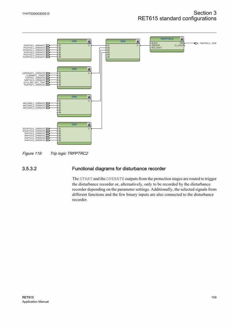
OR6B1B2B3B4B5B6
O
OR6B1B2B3B4B5B6
O
OR6B1B2B3B4B5B6
O
OR6B1B2B3B4B5B6
O
TRPPTRC2BLOCKOPERATERST_LKOUT
TRIPCL_LKOUT
OR6B1B2B3B4B5B6
O
TRPPTRC2_TRIPPHIPTOC1_OPERATEPHLPTOC1_OPERATEPHHPTOC1_OPERATE
LREFPNDF1_OPERATECCBRBRF1_TRRET
TR2PTDF1_OPERATEX110_BI2_EXT_TRIP
ARCSARC1_OPERATEARCSARC2_OPERATEARCSARC3_OPERATE
ROVPTOV1_OPERATEROVPTOV2_OPERATE
PHPTOV1_OPERATEPHPTOV2_OPERATEPHPTUV1_OPERATEPHPTUV2_OPERATE
PHIPTOC2_OPERATEPHLPTOC2_OPERATEPHHPTOC2_OPERATE
T2PTTR1_OPERATENSPTOC2_OPERATE
GUID-A3FF69AA-3162-4BA4-8275-69526091C00D V1 EN
Figure 119: Trip logic TRPPTRC2
3.5.3.2 Functional diagrams for disturbance recorder
The START and the OPERATE outputs from the protection stages are routed to triggerthe disturbance recorder or, alternatively, only to be recorded by the disturbancerecorder depending on the parameter settings. Additionally, the selected signals fromdifferent functions and the few binary inputs are also connected to the disturbancerecorder.
1YHT530003D05 D Section 3RET615 standard configurations
RET615 109Application Manual
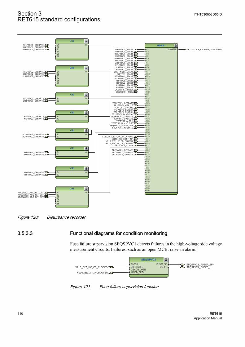
RDRE1C1C2C3C4C5C6C7C8C9C10C11C12C13C14C15C16C17C18C19C20C21C22C23C24C25C26C27C28C29C30C31C32C33C34C35C36C37C38C39C40C41C42C43C44C45C46C47C48C49C50C51C52C53C54C55C56C57C58C59C60C61C62C63C64
TRIGGERED
ORB1B2
O
ORB1B2
O
OR6B1B2B3B4B5B6
O
OR6B1B2B3B4B5B6
O
ORB1B2
O
ORB1B2
O
ORB1B2
O
OR6B1B2B3B4B5B6
O
CCBRBRF1_TRBU
X110_BI8_HV_CB_OPENEDX110_BI7_HV_CB_CLOSED
PHIPTOC1_OPERATEPHLPTOC1_OPERATE
PHHPTOC1_OPERATE
LREFPNDF1_OPERATE
CCBRBRF1_TRRET
NSPTOC1_OPERATE
TR2PTDF1_OPERATE
X110_BI2_EXT_TRIP
EFHPTOC1_OPERATEEFLPTOC1_OPERATE
ROVPTOV1_OPERATEROVPTOV2_OPERATE
PHPTOV1_OPERATEPHPTOV2_OPERATE
PHPTUV1_OPERATEPHPTUV2_OPERATE
ARCSARC1_OPERATEARCSARC2_OPERATEARCSARC3_OPERATE
PHIPTOC2_OPERATEPHLPTOC2_OPERATE
PHHPTOC2_OPERATE
T2PTTR1_OPERATENSPTOC2_OPERATE
PHIPTOC1_START
PHLPTOC1_STARTPHHPTOC1_START
PHLPTOC2_START
PHIPTOC2_STARTPHHPTOC2_START
EFHPTOC1_STARTEFLPTOC1_STARTNSPTOC1_STARTNSPTOC2_START
LREFPNDF1_STARTT2PTTR1_START
ROVPTOV1_STARTROVPTOV2_START
PHPTOV1_STARTPHPTOV2_STARTPHPTUV1_STARTPHPTUV2_START
X110_BI1_EXT_OC_BLOCKING
SEQSPVC1_FUSEF_U
TR2PTDF1_OPR_LSTR2PTDF1_OPR_HSTR2PTDF1_BLKD2HTR2PTDF1_BLKD5H
TR2PTDF1_BLKDWAV
T2PTTR1_ALARMT2PTTR1_BLK_CLOSE
SEQSPVC1_FUSEF_3PH
MDSOPT1_ALARM
ARCSARC1_ARC_FLT_DETARCSARC2_ARC_FLT_DETARCSARC3_ARC_FLT_DET
DISTURB_RECORD_TRIGGERED
GUID-4112309F-E61A-4835-BD1C-6DFAAC8074AC V2 EN
Figure 120: Disturbance recorder
3.5.3.3 Functional diagrams for condition monitoring
Fuse failure supervision SEQSPVC1 detects failures in the high-voltage side voltagemeasurement circuits. Failures, such as an open MCB, raise an alarm.
SEQSPVC1BLOCKCB_CLOSEDDISCON_OPENMINCB_OPEN
FUSEF_3PHFUSEF_UX110_BI7_HV_CB_CLOSED SEQSPVC1_FUSEF_U
X130_BI1_VT_MCB_OPEN
SEQSPVC1_FUSEF_3PH
GUID-95E67752-A435-47D3-B3AF-F530A23354E3 V2 EN
Figure 121: Fuse failure supervision function
Section 3 1YHT530003D05 DRET615 standard configurations
110 RET615Application Manual
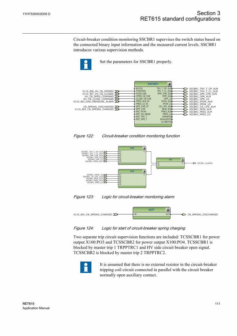
Circuit-breaker condition monitoring SSCBR1 supervises the switch status based onthe connected binary input information and the measured current levels. SSCBR1introduces various supervision methods.
Set the parameters for SSCBR1 properly.
SSCBR1BLOCKPOSOPENPOSCLOSEOPEN_CB_EXECLOSE_CB_EXEPRES_ALM_INPRES_LO_INSPR_CHR_STSPR_CHRRST_IPOWRST_CB_WEARRST_TRV_TRST_SPR_T
TRV_T_OP_ALMTRV_T_CL_ALMSPR_CHR_ALM
OPR_ALMOPR_LO
IPOW_ALMIPOW_LO
CB_LIFE_ALMMON_ALM
PRES_ALMPRES_LO
OPENPOSINVALIDPOSCLOSEPOS
HV_CB_CLOSE_COMMANDHV_CB_OPEN_COMMAND
X110_BI8_HV_CB_OPENEDX110_BI7_HV_CB_CLOSED
X110_BI3_GAS_PRESSURE_ALARM
X110_BI4_CB_SPRING_CHARGEDCB_SPRING_DISCHARGED
SSCBR1_TRV_T_OP_ALMSSCBR1_TRV_T_CL_ALMSSCBR1_SPR_CHR_ALMSSCBR1_OPR_ALMSSCBR1_OPR_LOSSCBR1_IPOW_ALMSSCBR1_IPOW_LOSSCBR1_CB_LIFE_ALMSSCBR1_MON_ALMSSCBR1_PRES_ALMSSCBR1_PRES_LO
GUID-B373C3BE-6A20-47C1-AF45-0F19F627EAD2 V1 EN
Figure 122: Circuit-breaker condition monitoring function
OR6B1B2B3B4B5B6
O
ORB1B2
O
OR6B1B2B3B4B5B6
OSSCBR1_TRV_T_OP_ALMSSCBR1_TRV_T_CL_ALMSSCBR1_SPR_CHR_ALM
SSCBR1_OPR_ALMSSCBR1_OPR_LO
SSCBR1_IPOW_ALM
SSCBR1_IPOW_LOSSCBR1_CB_LIFE_ALM
SSCBR1_MON_ALMSSCBR1_PRES_ALM
SSCBR1_PRES_LO
SSCBR1_ALARMS
GUID-8469F38F-3209-4C39-8A5C-B22A3AD306BF V1 EN
Figure 123: Logic for circuit-breaker monitoring alarm
NOTIN OUTX110_BI4_CB_SPRING_CHARGED CB_SPRING_DISCHARGED
GUID-0F6AC8DE-84AC-4BC3-9B63-765CF3AAA5DF V1 EN
Figure 124: Logic for start of circuit-breaker spring charging
Two separate trip circuit supervision functions are included: TCSSCBR1 for poweroutput X100:PO3 and TCSSCBR2 for power output X100:PO4. TCSSCBR1 isblocked by master trip 1 TRPPTRC1 and HV side circuit breaker open signal.TCSSCBR2 is blocked by master trip 2 TRPPTRC2.
It is assumed that there is no external resistor in the circuit-breakertripping coil circuit connected in parallel with the circuit breakernormally open auxiliary contact.
1YHT530003D05 D Section 3RET615 standard configurations
RET615 111Application Manual
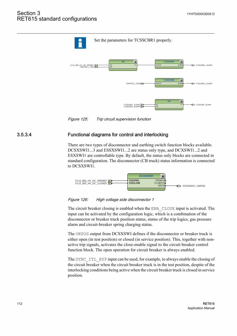
Set the parameters for TCSSCBR1 properly.
ORB1B2
OTCSSCBR1_ALARMTCSSCBR2_ALARM
TCSSCBR_ALARM
TCSSCBR1BLOCK ALARM
ORB1B2
OTRPPTRC1_TRIP
X110_BI8_HV_CB_OPENED TCSSCBR1_ALARM
TCSSCBR2BLOCK ALARMTRPPTRC2_TRIP TCSSCBR2_ALARM
GUID-E089AB37-001E-4FFF-9487-3D02CD39178F V1 EN
Figure 125: Trip circuit supervision function
3.5.3.4 Functional diagrams for control and interlocking
There are two types of disconnector and earthing switch function blocks available.DCSXSWI1...3 and ESSXSWI1...2 are status only type, and DCXSWI1...2 andESXSWI1 are controllable type. By default, the status only blocks are connected instandard configuration. The disconnector (CB truck) status information is connectedto DCSXSWI1.
DCSXSWI1POSOPENPOSCLOSE
OPENPOSCLOSEPOS
OKPOS DCSXSWI1_OKPOS
X110_BI6_HV_DC_OPENEDX110_BI5_HV_DC_CLOSED
GUID-BE83082B-13EE-4D4C-9FA1-FA49C85D463D V1 EN
Figure 126: High voltage side disconnector 1
The circuit breaker closing is enabled when the ENA_CLOSE input is activated. Theinput can be activated by the configuration logic, which is a combination of thedisconnector or breaker truck position status, status of the trip logics, gas pressurealarm and circuit-breaker spring charging status.
The OKPOS output from DCSXSWI defines if the disconnector or breaker truck iseither open (in test position) or closed (in service position). This, together with non-active trip signals, activates the close-enable signal to the circuit breaker controlfunction block. The open operation for circuit breaker is always enabled.
The SYNC_ITL_BYP input can be used, for example, to always enable the closing ofthe circuit breaker when the circuit breaker truck is in the test position, despite of theinterlocking conditions being active when the circuit breaker truck is closed in serviceposition.
Section 3 1YHT530003D05 DRET615 standard configurations
112 RET615Application Manual
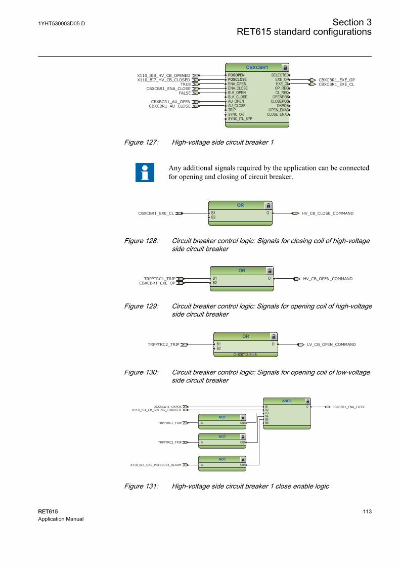
CBXCBR1POSOPENPOSCLOSEENA_OPENENA_CLOSEBLK_OPENBLK_CLOSEAU_OPENAU_CLOSETRIPSYNC_OKSYNC_ITL_BYP
SELECTEDEXE_OPEXE_CL
OP_REQCL_REQ
OPENPOSCLOSEPOS
OKPOSOPEN_ENAD
CLOSE_ENAD
TRUECBXCBR1_ENA_CLOSE
CBXCBR1_EXE_OPCBXCBR1_EXE_CL
X110_BI8_HV_CB_OPENEDX110_BI7_HV_CB_CLOSED
CBXBCR1_AU_OPENCBXCBR1_AU_CLOSE
FALSE
GUID-5F0A1E6E-BD0D-4EB9-B3A8-8C5A3F2F2E3C V2 EN
Figure 127: High-voltage side circuit breaker 1
Any additional signals required by the application can be connectedfor opening and closing of circuit breaker.
ORB1B2
O HV_CB_CLOSE_COMMANDCBXCBR1_EXE_CL
GUID-9EBFADE8-31A3-4401-B878-7838527797B2 V1 EN
Figure 128: Circuit breaker control logic: Signals for closing coil of high-voltageside circuit breaker
ORB1B2
O HV_CB_OPEN_COMMANDTRPPTRC1_TRIPCBXCBR1_EXE_OP
GUID-4D2894CF-3F0D-4A46-8BED-76C5D638E659 V1 EN
Figure 129: Circuit breaker control logic: Signals for opening coil of high-voltageside circuit breaker
OR
O:80|T:2.5|I:8
B1B2
O LV_CB_OPEN_COMMANDTRPPTRC2_TRIP
GUID-EBD43B3D-F992-4C8E-9160-9F306F58C524 V1 EN
Figure 130: Circuit breaker control logic: Signals for opening coil of low-voltageside circuit breaker
NOTIN OUT
AND6B1B2B3B4B5B6
O
NOTIN OUT
NOTIN OUT
TRPPTRC1_TRIP
CBXCBR1_ENA_CLOSE
X110_BI3_GAS_PRESSURE_ALARM
TRPPTRC2_TRIP
DCSXSWI1_OKPOSX110_BI4_CB_SPRING_CHARGED
GUID-903E890E-4F91-4E4A-AAEB-F475F8C07F87 V1 EN
Figure 131: High-voltage side circuit breaker 1 close enable logic
1YHT530003D05 D Section 3RET615 standard configurations
RET615 113Application Manual
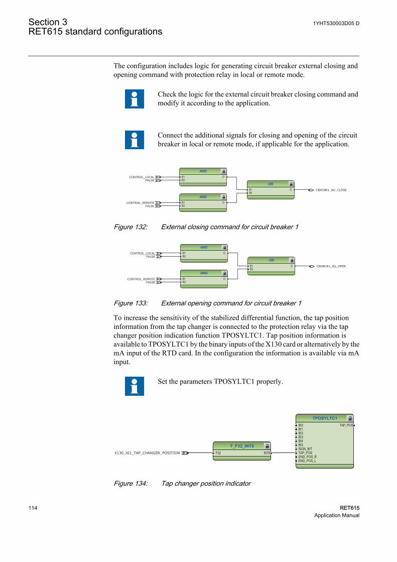
The configuration includes logic for generating circuit breaker external closing andopening command with protection relay in local or remote mode.
Check the logic for the external circuit breaker closing command andmodify it according to the application.
Connect the additional signals for closing and opening of the circuitbreaker in local or remote mode, if applicable for the application.
ANDB1B2
O
ANDB1B2
O
ORB1B2
O CBXCBR1_AU_CLOSE
CONTROL_LOCAL
CONTROL_REMOTE
FALSE
FALSE
GUID-08877BD4-93EB-4871-9487-BF36F5A393FC V1 EN
Figure 132: External closing command for circuit breaker 1
ANDB1B2
O
ORB1B2
O
ANDB1B2
O
CBXBCR1_AU_OPEN
CONTROL_LOCAL
CONTROL_REMOTE
FALSE
FALSE
GUID-CBCA8C3D-D7C2-4564-BDF8-22CB111BEC20 V1 EN
Figure 133: External opening command for circuit breaker 1
To increase the sensitivity of the stabilized differential function, the tap positioninformation from the tap changer is connected to the protection relay via the tapchanger position indication function TPOSYLTC1. Tap position information isavailable to TPOSYLTC1 by the binary inputs of the X130 card or alternatively by themA input of the RTD card. In the configuration the information is available via mAinput.
Set the parameters TPOSYLTC1 properly.
TPOSYLTC1BI0BI1BI2BI3BI4BI5SIGN_BITTAP_POSEND_POS_REND_POS_L
TAP_POS
T_F32_INT8F32 INT8X130_AI1_TAP_CHANGER_POSITION
GUID-3F9A3F96-B3D2-4C85-B4F6-AA2FD6A3BE88 V2 EN
Figure 134: Tap changer position indicator
Section 3 1YHT530003D05 DRET615 standard configurations
114 RET615Application Manual
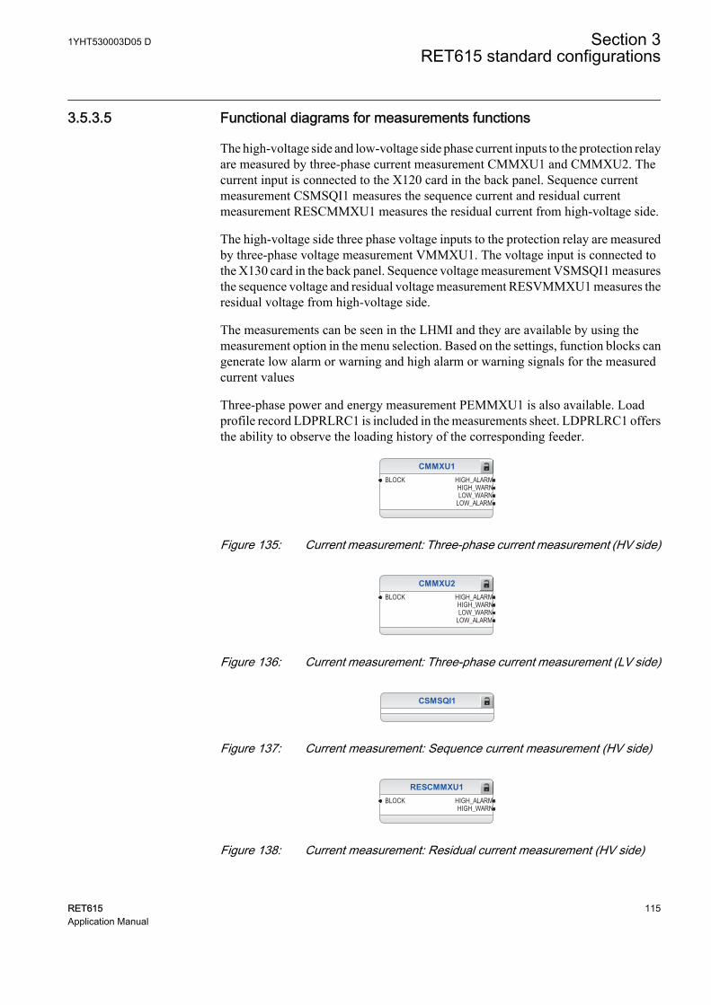
3.5.3.5 Functional diagrams for measurements functions
The high-voltage side and low-voltage side phase current inputs to the protection relayare measured by three-phase current measurement CMMXU1 and CMMXU2. Thecurrent input is connected to the X120 card in the back panel. Sequence currentmeasurement CSMSQI1 measures the sequence current and residual currentmeasurement RESCMMXU1 measures the residual current from high-voltage side.
The high-voltage side three phase voltage inputs to the protection relay are measuredby three-phase voltage measurement VMMXU1. The voltage input is connected tothe X130 card in the back panel. Sequence voltage measurement VSMSQI1 measuresthe sequence voltage and residual voltage measurement RESVMMXU1 measures theresidual voltage from high-voltage side.
The measurements can be seen in the LHMI and they are available by using themeasurement option in the menu selection. Based on the settings, function blocks cangenerate low alarm or warning and high alarm or warning signals for the measuredcurrent values
Three-phase power and energy measurement PEMMXU1 is also available. Loadprofile record LDPRLRC1 is included in the measurements sheet. LDPRLRC1 offersthe ability to observe the loading history of the corresponding feeder.
CMMXU1BLOCK HIGH_ALARM
HIGH_WARNLOW_WARN
LOW_ALARM
GUID-B16958D8-EE50-4895-A162-DE0913E05489 V1 EN
Figure 135: Current measurement: Three-phase current measurement (HV side)
CMMXU2BLOCK HIGH_ALARM
HIGH_WARNLOW_WARN
LOW_ALARM
GUID-53274EB2-39DE-44D9-9D27-8ECE4B1639F5 V1 EN
Figure 136: Current measurement: Three-phase current measurement (LV side)
CSMSQI1
GUID-E2ECEE96-E50C-45C6-939D-5D91D2BD556B V1 EN
Figure 137: Current measurement: Sequence current measurement (HV side)
RESCMMXU1BLOCK HIGH_ALARM
HIGH_WARN
GUID-72175257-3313-4787-9FB7-1B13D6B881C5 V1 EN
Figure 138: Current measurement: Residual current measurement (HV side)
1YHT530003D05 D Section 3RET615 standard configurations
RET615 115Application Manual
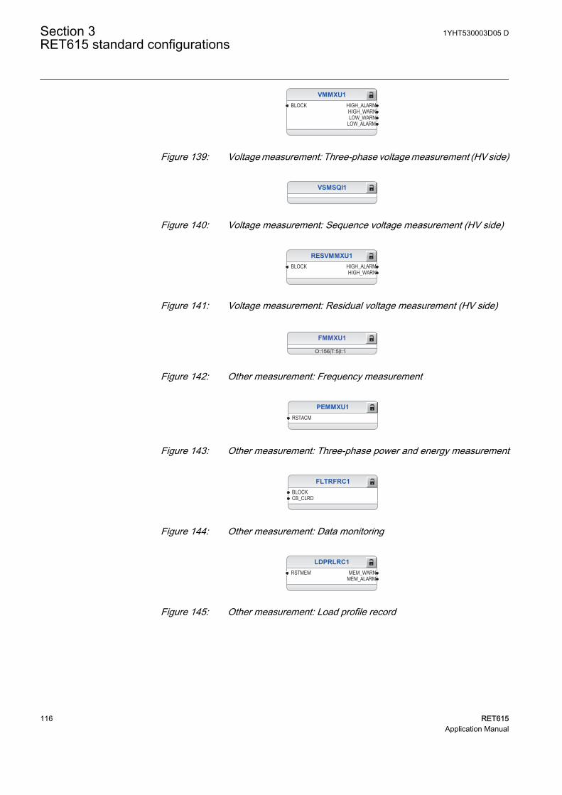
VMMXU1BLOCK HIGH_ALARM
HIGH_WARNLOW_WARN
LOW_ALARM
GUID-217DCB6B-6B4E-4FC2-980A-2B48A3A476C0 V1 EN
Figure 139: Voltage measurement: Three-phase voltage measurement (HV side)
VSMSQI1
GUID-F2D698F9-7A31-4EB2-A03A-3DEA3E8B8DF0 V1 EN
Figure 140: Voltage measurement: Sequence voltage measurement (HV side)
RESVMMXU1BLOCK HIGH_ALARM
HIGH_WARN
GUID-B29947B9-C3A8-4FB3-9967-B401DD935F6D V1 EN
Figure 141: Voltage measurement: Residual voltage measurement (HV side)
FMMXU1
O:156|T:5|I:1GUID-C23314B1-B895-42F7-8CFE-C605AC589906 V1 EN
Figure 142: Other measurement: Frequency measurement
PEMMXU1RSTACM
GUID-05841EEF-D1BD-44AD-81A9-FE157B84D70D V1 EN
Figure 143: Other measurement: Three-phase power and energy measurement
FLTRFRC1BLOCKCB_CLRD
GUID-C2DCB832-45FB-40EE-801F-83983388EE3B V2 EN
Figure 144: Other measurement: Data monitoring
LDPRLRC1RSTMEM MEM_WARN
MEM_ALARM
GUID-8BE212AA-C9AC-4F4B-9FDE-5B4E0287703B V2 EN
Figure 145: Other measurement: Load profile record
Section 3 1YHT530003D05 DRET615 standard configurations
116 RET615Application Manual
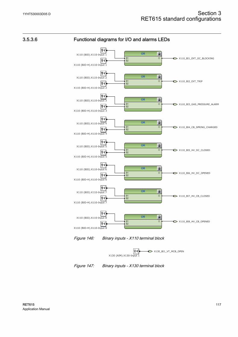
3.5.3.6 Functional diagrams for I/O and alarms LEDs
ORB1B2
O
ORB1B2
O
ORB1B2
O
ORB1B2
O
ORB1B2
O
ORB1B2
O
ORB1B2
O
ORB1B2
O X110_BI8_HV_CB_OPENED
X110_BI7_HV_CB_CLOSED
X110_BI3_GAS_PRESSURE_ALARM
X110_BI4_CB_SPRING_CHARGED
X110_BI6_HV_DC_OPENED
X110_BI5_HV_DC_CLOSED
X110_BI2_EXT_TRIP
X110_BI1_EXT_OC_BLOCKING
X110 (BIO).X110-Input 6
X110 (BIO).X110-Input 2
X110 (BIO).X110-Input 1
X110 (BIO-H).X110-Input 4
X110 (BIO-H).X110-Input 3
X110 (BIO).X110-Input 5
X110 (BIO-H).X110-Input 2
X110 (BIO-H).X110-Input 5
X110 (BIO).X110-Input 3
X110 (BIO).X110-Input 8
X110 (BIO-H).X110-Input 7
X110 (BIO-H).X110-Input 6
X110 (BIO-H).X110-Input 8
X110 (BIO).X110-Input 7
X110 (BIO-H).X110-Input 1
X110 (BIO).X110-Input 4
GUID-3734A47A-5BD8-4AB6-AE16-9DD332C6A36D V1 EN
Figure 146: Binary inputs - X110 terminal block
X130_BI1_VT_MCB_OPEN
X130 (AIM).X130-Input 1GUID-0A1FB88E-FAFE-43BF-980E-E14FBA95607C V1 EN
Figure 147: Binary inputs - X130 terminal block
1YHT530003D05 D Section 3RET615 standard configurations
RET615 117Application Manual
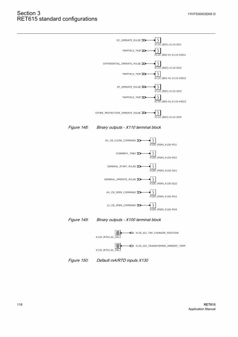
OC_OPERATE_PULSE
DIFFERENTIAL_OPERATE_PULSE
EF_OPERATE_PULSE
OTHER_PROTECTION_OPERATE_PULSE
TRPPTRC3_TRIP
TRPPTRC4_TRIP
TRPPTRC5_TRIP
X110 (BIO).X110-SO1
X110 (BIO).X110-SO2
X110 (BIO).X110-SO4
X110 (BIO).X110-SO3
X110 (BIO-H).X110-HSO1
X110 (BIO-H).X110-HSO2
X110 (BIO-H).X110-HSO3
GUID-5E404CF7-5636-45F3-89C3-E12C516A26CE V1 EN
Figure 148: Binary outputs - X110 terminal block
GENERAL_START_PULSE
GENERAL_OPERATE_PULSE
LV_CB_OPEN_COMMAND
CCBRBRF1_TRBU
HV_CB_CLOSE_COMMAND
HV_CB_OPEN_COMMAND
X100 (PSM).X100-PO1
X100 (PSM).X100-PO2
X100 (PSM).X100-SO1
X100 (PSM).X100-SO2
X100 (PSM).X100-PO3
X100 (PSM).X100-PO4GUID-5DF67D6C-F0E3-4F1C-A9FF-9BDDE42BEF4B V1 EN
Figure 149: Binary outputs - X100 terminal block
X130_AI1_TAP_CHANGER_POSITION
X130 (RTD).AI_VAL1
X130_AI3_TRANSFORMER_AMBIENT_TEMP
X130 (RTD).AI_VAL3GUID-196E11DA-B142-45B6-8BC9-4C40DE7D3929 V1 EN
Figure 150: Default mA/RTD inputs X130
Section 3 1YHT530003D05 DRET615 standard configurations
118 RET615Application Manual
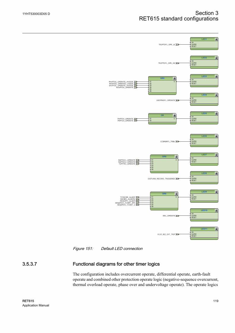
LED1OKALARMRESET
LED2OKALARMRESET
LED3OKALARMRESET
LED4OKALARMRESET
LED5OKALARMRESET
OR6B1B2B3B4B5B6
O
ORB1B2
O
LREFPNDF1_OPERATE
PHxPTOC_OPERATE_HVSIDEPHxPTOC_OPERATE_LVSIDEEFxPTOC_OPERATE_HVSIDE
ROVPTOV_OPERATE
PHPTOV_OPERATEPHPTUV_OPERATE
TR2PTDF1_OPR_LS
TR2PTDF1_OPR_HS
GUID-CD38B15D-CAAA-4552-ABAB-A201E31D0331 V2 EN
LED6OKALARMRESET
LED7OKALARMRESET
LED8OKALARMRESET
LED9OKALARMRESET
LED10OKALARMRESET
LED11OKALARMRESET
OR6B1B2B3B4B5B6
O
OR6B1B2B3B4B5B6
O
CCBRBRF1_TRBU
NSPTOC1_OPERATE
X110_BI2_EXT_TRIP
T2PTTR1_OPERATENSPTOC2_OPERATE
SEQSPVC1_FUSEF_USEQSPVC1_FUSEF_3PH
MDSOPT1_ALARM
TCSSCBR_ALARMSSCBR1_ALARMS
DISTURB_RECORD_TRIGGERED
ARC_OPERATE
GUID-28E7CEDC-73EF-4601-B9D9-92169089C54F V2 EN
Figure 151: Default LED connection
3.5.3.7 Functional diagrams for other timer logics
The configuration includes overcurrent operate, differential operate, earth-faultoperate and combined other protection operate logic (negative-sequence overcurrent,thermal overload operate, phase over and undervoltage operate). The operate logics
1YHT530003D05 D Section 3RET615 standard configurations
RET615 119Application Manual
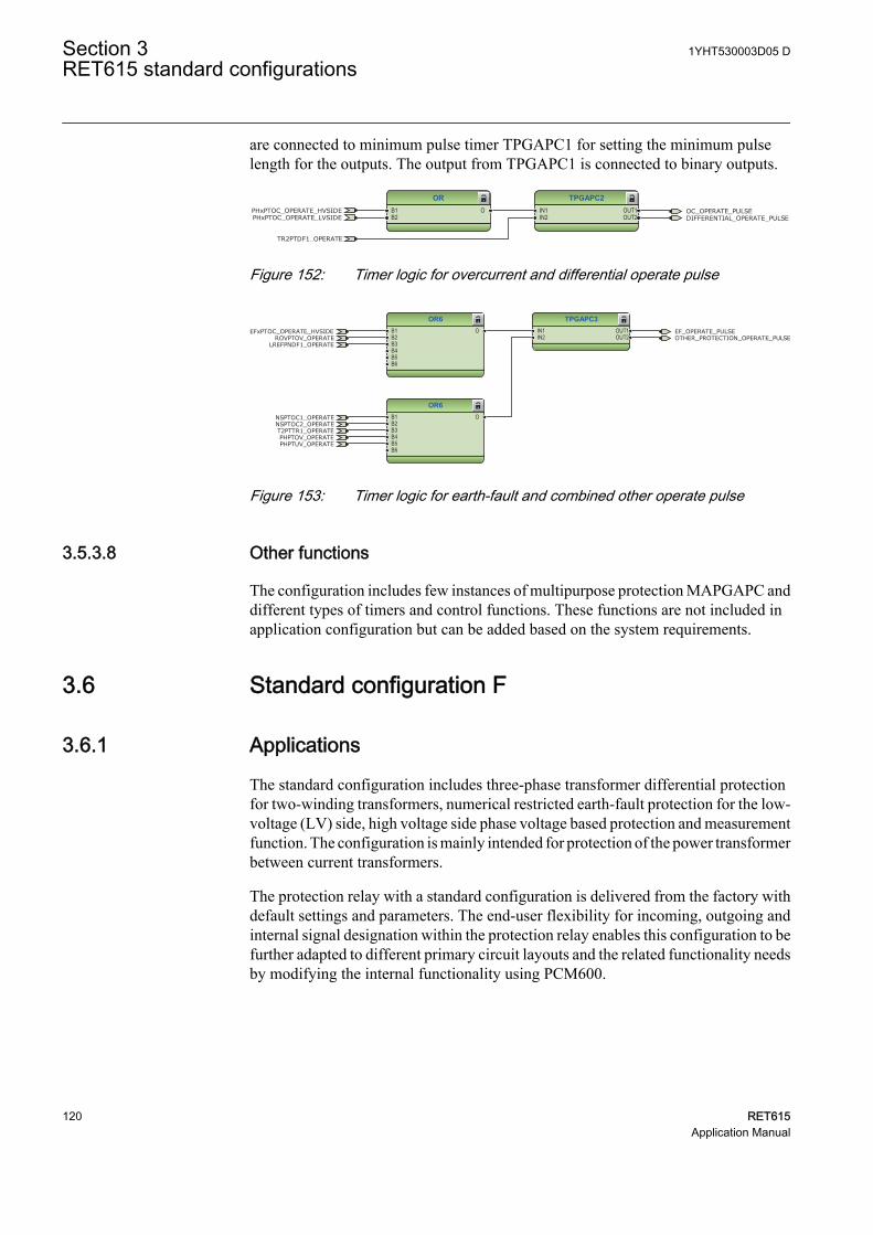
are connected to minimum pulse timer TPGAPC1 for setting the minimum pulselength for the outputs. The output from TPGAPC1 is connected to binary outputs.
TPGAPC2IN1IN2
OUT1OUT2
ORB1B2
O OC_OPERATE_PULSEDIFFERENTIAL_OPERATE_PULSE
TR2PTDF1_OPERATE
PHxPTOC_OPERATE_HVSIDEPHxPTOC_OPERATE_LVSIDE
GUID-4B5B49BB-65C0-4120-A5F9-410B111BD598 V1 EN
Figure 152: Timer logic for overcurrent and differential operate pulse
TPGAPC3IN1IN2
OUT1OUT2
OR6B1B2B3B4B5B6
O
OR6B1B2B3B4B5B6
O
EF_OPERATE_PULSEOTHER_PROTECTION_OPERATE_PULSE
LREFPNDF1_OPERATE
NSPTOC1_OPERATE
T2PTTR1_OPERATENSPTOC2_OPERATE
EFxPTOC_OPERATE_HVSIDEROVPTOV_OPERATE
PHPTOV_OPERATEPHPTUV_OPERATE
GUID-C828CB50-6FE6-463D-8CB8-9EE6AD3D7389 V1 EN
Figure 153: Timer logic for earth-fault and combined other operate pulse
3.5.3.8 Other functions
The configuration includes few instances of multipurpose protection MAPGAPC anddifferent types of timers and control functions. These functions are not included inapplication configuration but can be added based on the system requirements.
3.6 Standard configuration F
3.6.1 Applications
The standard configuration includes three-phase transformer differential protectionfor two-winding transformers, numerical restricted earth-fault protection for the low-voltage (LV) side, high voltage side phase voltage based protection and measurementfunction. The configuration is mainly intended for protection of the power transformerbetween current transformers.
The protection relay with a standard configuration is delivered from the factory withdefault settings and parameters. The end-user flexibility for incoming, outgoing andinternal signal designation within the protection relay enables this configuration to befurther adapted to different primary circuit layouts and the related functionality needsby modifying the internal functionality using PCM600.
Section 3 1YHT530003D05 DRET615 standard configurations
120 RET615Application Manual
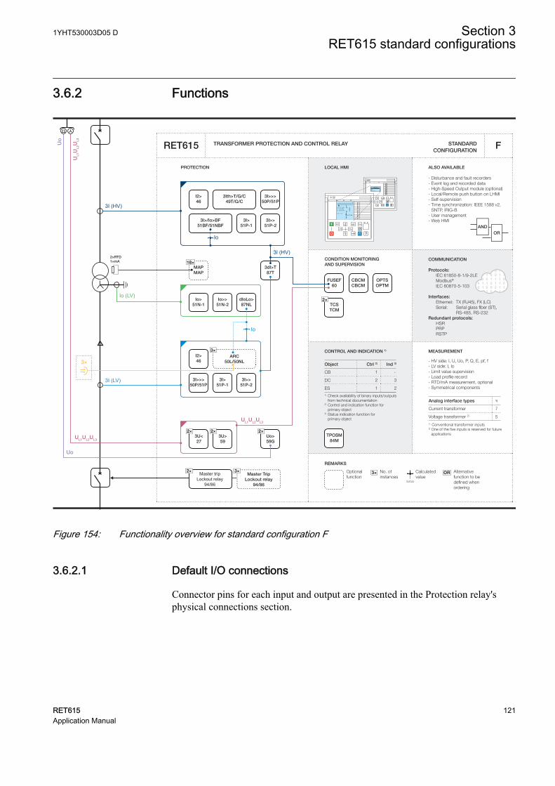
3.6.2 Functions
Master tripLockout relay
94/86
2×RTD1×mA CONDITION MONITORING
AND SUPERVISION
ALSO AVAILABLE
- Disturbance and fault recorders- Event log and recorded data- High-Speed Output module (optional)- Local/Remote push button on LHMI- Self-supervision- Time synchronization: IEEE 1588 v2,
SNTP, IRIG-B- User management- Web HMI
ORAND
CONTROL AND INDICATION 1) MEASUREMENT
TRANSFORMER PROTECTION AND CONTROL RELAY
PROTECTION LOCAL HMI
Object Ctrl 2) Ind 3)
CB
DC
ES1) Check availability of binary inputs/outputs
from technical documentation2) Control and indication function for
primary object3) Status indication function for primary object
1 -
2 3
1 2
STANDARD CONFIGURATION
REMARKS
Optionalfunction
No. ofinstances
Alternative function to be defined when ordering
OR
Io/Uo
Calculatedvalue
3×
RL
ClearESCI
O
Configuration ASystemHMITimeAuthorization
RL
ClearESCI
O
U12 0. 0 kVP 0.00 kWQ 0.00 kVAr
IL2 0 A
A
COMMUNICATION
Protocols: IEC 61850-8-1/9-2LE Modbus®
IEC 60870-5-103 Interfaces: Ethernet: TX (RJ45), FX (LC) Serial: Serial glass fiber (ST), RS-485, RS-232Redundant protocols: HSR PRP RSTP
RET615 F
7
5
Analog interface types 1)
Current transformer
1) Conventional transformer inputs
Voltage transformer 2)
2) One of the five inputs is reserved for future applications
- HV side: I, U, Uo, P, Q, E, pf, f - LV side: I, Io- Limit value supervision- Load profile record- RTD/mA measurement, optional- Symmetrical components
3Ith>T/G/C49T/G/C
I2>46
3I>>>50P/51P
3I>/Io>BF51BF/51NBF
3I>51P-1
3I>>51P-2
3dI>T87T
I2>46
3×ARC
50L/50NL
3I>>51P-2
3I>>>50P/51P
3I>51P-1
2×3U<27
2×Uo>59G
2×TCSTCM
CBCMCBCM
OPTSOPTM
FUSEF60
2×3U>59
TPOSM84M
Io>51N-1
Io>>51N-2
dIoLo>87NL
18×MAPMAP
3I (LV)
UL1UL2UL3
Uo
3I (HV)
UL1UL2UL3
Io (LV)
Io
3×
3I (HV)
Io
UL1
UL2
UL3
Uo
Master TripLockout relay
94/86
3×2×
GUID-3BB5F36E-E8FA-464E-AEDD-EFBCA6866BFE V1 EN
Figure 154: Functionality overview for standard configuration F
3.6.2.1 Default I/O connections
Connector pins for each input and output are presented in the Protection relay'sphysical connections section.
1YHT530003D05 D Section 3RET615 standard configurations
RET615 121Application Manual

Table 30: Default connections for analog inputs
Analog input Description Connector pinsIL1B Phase A current, LV side X120:1-2
IL2B Phase B current, LV side X120:3-4
IL3B Phase C current, LV side X120:5-6
IL1 Phase A current, HV side X120:7-8
IL2 Phase B current, HV side X120:9-10
IL3 Phase C current, HV side X120:11-12
Io Residual current X120:13-14
U1 Phase voltage U1 X130:11-12
U2 Phase voltage U2 X130:13-14
U3 Phase voltage U3 X130:15-16
Uo Residual voltage X130:17-18
mA1 - X130:1-2
RTD1 - X130:3-4
RTD2 - X130:6-7
AI1 Tap changer position X130:1-2
AI2 - X130:3-4
AI3 Ambient temperature X130:5-6
AI4 - X130:7-8
AI5 - X130:9-10
AI6 - X130:13-14
AI7 - X130:15-16
AI8 - X130:17-18
Table 31: Default connections for binary inputs
Binary input Description Connector pinsBIO0005 BIO0007
X110-BI1 Blocking of overcurrent high state (high voltage) andinstantaneous stage (medium voltage)
X110:1-2 X110:1,5
X110-BI2 External protection trip X110:3-4 X110:2,5
X110-BI3 Circuit breaker low gas pressure indication X110:5-6 X110:3,5
X110-BI4 Circuit breaker spring charged indication X110:7-6 X110:4-5
X110-BI5 High-voltage side disconnector closed indication X110:8-9 X110:6,10
X110-BI6 High-voltage side disconnector open indication X110:10-9 X110:7,10
X110-BI7 High-voltage side circuit breaker closed indication X110:11-12 X110:8,10
X110-BI8 High-voltage side circuit breaker open indication X110:13-12 X110:9-10
X130-BI1 Voltage transformer secondary MCB open X130:1-2
X130-BI2 - X130:3-4
X130-BI3 - X130:5-6
X130-BI4 - X130:7-8
Section 3 1YHT530003D05 DRET615 standard configurations
122 RET615Application Manual

Table 32: Default connections for binary outputs
Binary output Description Connector pinsX100-PO1 Close high-voltage circuit breaker X100:6-7
X100-PO2 Breaker failure backup trip to upstream breaker(Breaker 1 and 2)
X100:8-9
X100-SO1 General start indication X100:10-11,(12)
X100-SO2 General operate indication X100:13-14
X100-PO3 Open circuit breaker/trip coil 1 high-voltage X100:15-19
X100-PO4 Open circuit breaker/trip coil 2 low-voltage X100:20-24
X110-SO1 Overcurrent operate alarm X110:14-16
X110-SO2 Differential protection operate alarm X110:17-19
X110-SO3 Earth-fault operate alarm X110:20-22
X110-SO4 Thermal overload and negative phase-sequenceoperate alarm
X110:23-24
X110-HSO1 Arc protection instance 1 trip activated X110:15-16
X110-HSO1 Arc protection instance 2 trip activated X110:19-20
X110-HSO1 Arc protection instance 3 trip activated X110:23-24
Table 33: Default connections for LEDs
LED Description1 Transformer differential protection biased stage operate
2 Transformer differential protection instantaneous stage operate
3 Overcurrent or earth-fault protection operate
4 Restricted earth-fault protection operate
5 Voltage protection operate
6 Circuit failure protection backup operate
7 Negative sequence overcurrent or thermal overload protection operate
8 Disturbance recorder triggered
9 TCS, fuse failure, measuring circuit fault or circuit breaker supervision
10 Arc protection operate
11 Protection trip from external device
3.6.2.2 Default disturbance recorder settings
Table 34: Default disturbance recorder analog channels
Channel Description1)
1 IL1
2 IL2
3 IL3
4 IL1B
Table continues on next page
1YHT530003D05 D Section 3RET615 standard configurations
RET615 123Application Manual
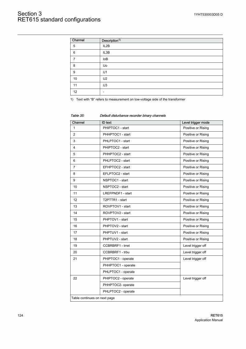
Channel Description1)
5 IL2B
6 IL3B
7 IoB
8 Uo
9 U1
10 U2
11 U3
12 -
1) Text with “B” refers to measurement on low-voltage side of the transformer
Table 35: Default disturbance recorder binary channels
Channel ID text Level trigger mode1 PHIPTOC1 - start Positive or Rising
2 PHHPTOC1 - start Positive or Rising
3 PHLPTOC1 - start Positive or Rising
4 PHIPTOC2 - start Positive or Rising
5 PHHPTOC2 - start Positive or Rising
6 PHLPTOC2 - start Positive or Rising
7 EFHPTOC2 - start Positive or Rising
8 EFLPTOC2 - start Positive or Rising
9 NSPTOC1 - start Positive or Rising
10 NSPTOC2 - start Positive or Rising
11 LREFPNDF1 - start Positive or Rising
12 T2PTTR1 - start Positive or Rising
13 ROVPTOV1 - start Positive or Rising
14 ROVPTOV2 - start Positive or Rising
15 PHPTOV1 - start Positive or Rising
16 PHPTOV2 - start Positive or Rising
17 PHPTUV1 - start Positive or Rising
18 PHPTUV2 - start Positive or Rising
19 CCBRBRF1 - trret Level trigger off
20 CCBRBRF1 - trbu Level trigger off
21 PHIPTOC1 - operate Level trigger off
PHHPTOC1 - operate
PHLPTOC1 - operate
22 PHIPTOC2 - operate Level trigger off
PHHPTOC2- operate
PHLPTOC2 - operate
Table continues on next page
Section 3 1YHT530003D05 DRET615 standard configurations
124 RET615Application Manual

Channel ID text Level trigger mode23 EFLPTOC2 - operate Level trigger off
EFHPTOC2 - operate
24 NSPTOC1 - operate Level trigger off
NSPTOC2 - operate
25 TR2PTDF1 - operate Positive or Rising
26 TR2PTDF1 - opr LS Level trigger off
27 TR2PTDF1 - opr HS Level trigger off
28 TR2PTDF1 - blkd2h Level trigger off
29 TR2PTDF1 - blkd5h Level trigger off
30 TR2PTDF1 - blkdwav Level trigger off
31 LREFPNDF1 - operate Level trigger off
32 T2PTTR1 - operate Level trigger off
33 T2PTTR1 - alarm Level trigger off
34 T2PTTR1 - blk close Level trigger off
35 SEQSPVC1 - fusef3ph Level trigger off
36 SEQSPVC1 - fusefu Level trigger off
37 ROVPTOV1 - operate Level trigger off
ROVPTOV2 - operate
38 PHPTOV1 - operate Level trigger off
PHPTOV2 - operate
39 PHPTUV1 - operate Level trigger off
PHPTUV2 - operate
40 X110BI1 - ext OC blocking Level trigger off
41 X110BI2 - ext operate Positive or Rising
42 X110BI7 - HVCB closed Level trigger off
43 X110BI8 - HVCB open Level trigger off
44 MDSOPT1 - alarm Level trigger off
45 ARCSARC1 - ARC flt det Level trigger off
ARCSARC2 - ARC flt det
ARCSARC3 - ARC flt det
46 ARCSARC1 - operate Positive or Rising
47 ARCSARC2 - operate Positive or Rising
48 ARCSARC3 - operate Positive or Rising
49 - -
50 - -
51 - -
52 - -
53 - -
54 - -
Table continues on next page
1YHT530003D05 D Section 3RET615 standard configurations
RET615 125Application Manual
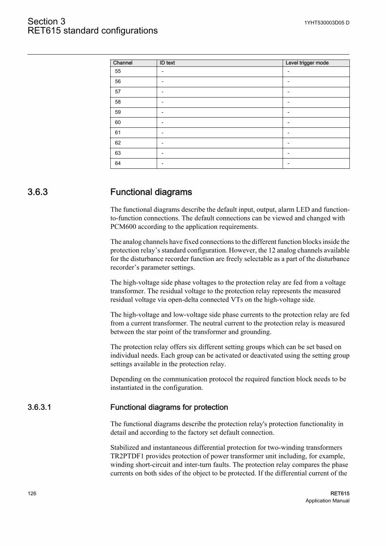
Channel ID text Level trigger mode55 - -
56 - -
57 - -
58 - -
59 - -
60 - -
61 - -
62 - -
63 - -
64 - -
3.6.3 Functional diagrams
The functional diagrams describe the default input, output, alarm LED and function-to-function connections. The default connections can be viewed and changed withPCM600 according to the application requirements.
The analog channels have fixed connections to the different function blocks inside theprotection relay’s standard configuration. However, the 12 analog channels availablefor the disturbance recorder function are freely selectable as a part of the disturbancerecorder’s parameter settings.
The high-voltage side phase voltages to the protection relay are fed from a voltagetransformer. The residual voltage to the protection relay represents the measuredresidual voltage via open-delta connected VTs on the high-voltage side.
The high-voltage and low-voltage side phase currents to the protection relay are fedfrom a current transformer. The neutral current to the protection relay is measuredbetween the star point of the transformer and grounding.
The protection relay offers six different setting groups which can be set based onindividual needs. Each group can be activated or deactivated using the setting groupsettings available in the protection relay.
Depending on the communication protocol the required function block needs to beinstantiated in the configuration.
3.6.3.1 Functional diagrams for protection
The functional diagrams describe the protection relay's protection functionality indetail and according to the factory set default connection.
Stabilized and instantaneous differential protection for two-winding transformersTR2PTDF1 provides protection of power transformer unit including, for example,winding short-circuit and inter-turn faults. The protection relay compares the phasecurrents on both sides of the object to be protected. If the differential current of the
Section 3 1YHT530003D05 DRET615 standard configurations
126 RET615Application Manual
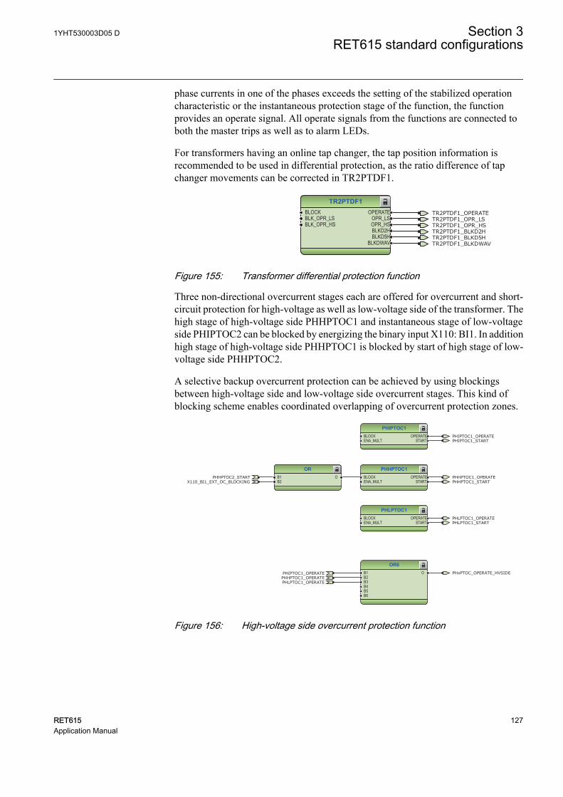
phase currents in one of the phases exceeds the setting of the stabilized operationcharacteristic or the instantaneous protection stage of the function, the functionprovides an operate signal. All operate signals from the functions are connected toboth the master trips as well as to alarm LEDs.
For transformers having an online tap changer, the tap position information isrecommended to be used in differential protection, as the ratio difference of tapchanger movements can be corrected in TR2PTDF1.
TR2PTDF1BLOCKBLK_OPR_LSBLK_OPR_HS
OPERATEOPR_LSOPR_HSBLKD2HBLKD5H
BLKDWAV
TR2PTDF1_OPERATETR2PTDF1_OPR_LSTR2PTDF1_OPR_HSTR2PTDF1_BLKD2HTR2PTDF1_BLKD5HTR2PTDF1_BLKDWAV
GUID-4C0CE6C5-A670-4280-A23E-BA79ADB1BA3D V1 EN
Figure 155: Transformer differential protection function
Three non-directional overcurrent stages each are offered for overcurrent and short-circuit protection for high-voltage as well as low-voltage side of the transformer. Thehigh stage of high-voltage side PHHPTOC1 and instantaneous stage of low-voltageside PHIPTOC2 can be blocked by energizing the binary input X110: BI1. In additionhigh stage of high-voltage side PHHPTOC1 is blocked by start of high stage of low-voltage side PHHPTOC2.
A selective backup overcurrent protection can be achieved by using blockingsbetween high-voltage side and low-voltage side overcurrent stages. This kind ofblocking scheme enables coordinated overlapping of overcurrent protection zones.
PHIPTOC1BLOCKENA_MULT
OPERATESTART
PHLPTOC1BLOCKENA_MULT
OPERATESTART
PHHPTOC1BLOCKENA_MULT
OPERATESTART
ORB1B2
O
OR6B1B2B3B4B5B6
O
PHIPTOC1_OPERATE
PHIPTOC1_OPERATE
PHLPTOC1_OPERATE
PHLPTOC1_OPERATE
PHHPTOC1_OPERATE
PHHPTOC1_OPERATE
PHIPTOC1_START
PHLPTOC1_START
PHHPTOC1_STARTPHHPTOC2_START
X110_BI1_EXT_OC_BLOCKING
PHxPTOC_OPERATE_HVSIDE
GUID-C13793C9-8CC2-41DF-9AFD-1E5480A8730F V1 EN
Figure 156: High-voltage side overcurrent protection function
1YHT530003D05 D Section 3RET615 standard configurations
RET615 127Application Manual
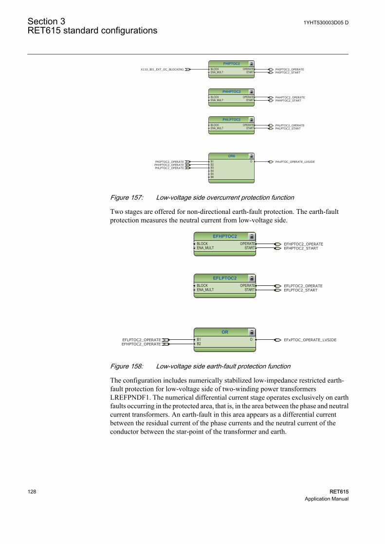
PHIPTOC2BLOCKENA_MULT
OPERATESTART
PHHPTOC2BLOCKENA_MULT
OPERATESTART
PHLPTOC2BLOCKENA_MULT
OPERATESTART
OR6B1B2B3B4B5B6
O
PHIPTOC2_OPERATE
PHIPTOC2_OPERATE
PHLPTOC2_OPERATE
PHLPTOC2_OPERATE
PHHPTOC2_OPERATE
PHHPTOC2_OPERATE
PHLPTOC2_START
PHIPTOC2_START
PHHPTOC2_START
X110_BI1_EXT_OC_BLOCKING
PHxPTOC_OPERATE_LVSIDE
GUID-02400495-65EA-4F48-9928-EF7DC04EA99B V1 EN
Figure 157: Low-voltage side overcurrent protection function
Two stages are offered for non-directional earth-fault protection. The earth-faultprotection measures the neutral current from low-voltage side.
ORB1B2
OEFLPTOC2_OPERATEEFHPTOC2_OPERATE
EFxPTOC_OPERATE_LVSIDE
EFHPTOC2BLOCKENA_MULT
OPERATESTART
EFLPTOC2BLOCKENA_MULT
OPERATESTART
EFLPTOC2_OPERATE
EFHPTOC2_OPERATEEFHPTOC2_START
EFLPTOC2_START
GUID-23ECC40C-6957-4908-8F86-009070A60BF7 V1 EN
Figure 158: Low-voltage side earth-fault protection function
The configuration includes numerically stabilized low-impedance restricted earth-fault protection for low-voltage side of two-winding power transformersLREFPNDF1. The numerical differential current stage operates exclusively on earthfaults occurring in the protected area, that is, in the area between the phase and neutralcurrent transformers. An earth-fault in this area appears as a differential currentbetween the residual current of the phase currents and the neutral current of theconductor between the star-point of the transformer and earth.
Section 3 1YHT530003D05 DRET615 standard configurations
128 RET615Application Manual
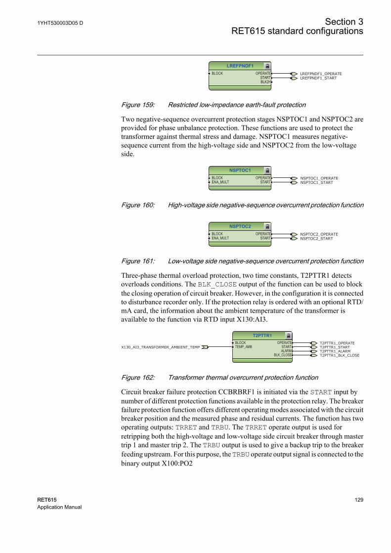
LREFPNDF1BLOCK OPERATE
STARTBLK2H
LREFPNDF1_OPERATELREFPNDF1_START
GUID-27CC861A-31C5-4EC8-8523-13FEC072F109 V1 EN
Figure 159: Restricted low-impedance earth-fault protection
Two negative-sequence overcurrent protection stages NSPTOC1 and NSPTOC2 areprovided for phase unbalance protection. These functions are used to protect thetransformer against thermal stress and damage. NSPTOC1 measures negative-sequence current from the high-voltage side and NSPTOC2 from the low-voltageside.
NSPTOC1BLOCKENA_MULT
OPERATESTART
NSPTOC1_OPERATENSPTOC1_START
GUID-5DEBA3D7-FB84-429E-B2A9-F29CFDE2CA8B V1 EN
Figure 160: High-voltage side negative-sequence overcurrent protection function
NSPTOC2BLOCKENA_MULT
OPERATESTART
NSPTOC2_OPERATENSPTOC2_START
GUID-B0A7C129-4864-461A-A12D-D995E0CA4302 V1 EN
Figure 161: Low-voltage side negative-sequence overcurrent protection function
Three-phase thermal overload protection, two time constants, T2PTTR1 detectsoverloads conditions. The BLK_CLOSE output of the function can be used to blockthe closing operation of circuit breaker. However, in the configuration it is connectedto disturbance recorder only. If the protection relay is ordered with an optional RTD/mA card, the information about the ambient temperature of the transformer isavailable to the function via RTD input X130:AI3.
T2PTTR1BLOCKTEMP_AMB
OPERATESTARTALARM
BLK_CLOSE
T2PTTR1_OPERATET2PTTR1_STARTX130_AI3_TRANSFORMER_AMBIENT_TEMPT2PTTR1_ALARMT2PTTR1_BLK_CLOSE
GUID-3FFBE716-DDE7-4026-95A6-52DC1690CFF9 V1 EN
Figure 162: Transformer thermal overcurrent protection function
Circuit breaker failure protection CCBRBRF1 is initiated via the START input bynumber of different protection functions available in the protection relay. The breakerfailure protection function offers different operating modes associated with the circuitbreaker position and the measured phase and residual currents. The function has twooperating outputs: TRRET and TRBU. The TRRET operate output is used forretripping both the high-voltage and low-voltage side circuit breaker through mastertrip 1 and master trip 2. The TRBU output is used to give a backup trip to the breakerfeeding upstream. For this purpose, the TRBU operate output signal is connected to thebinary output X100:PO2
1YHT530003D05 D Section 3RET615 standard configurations
RET615 129Application Manual
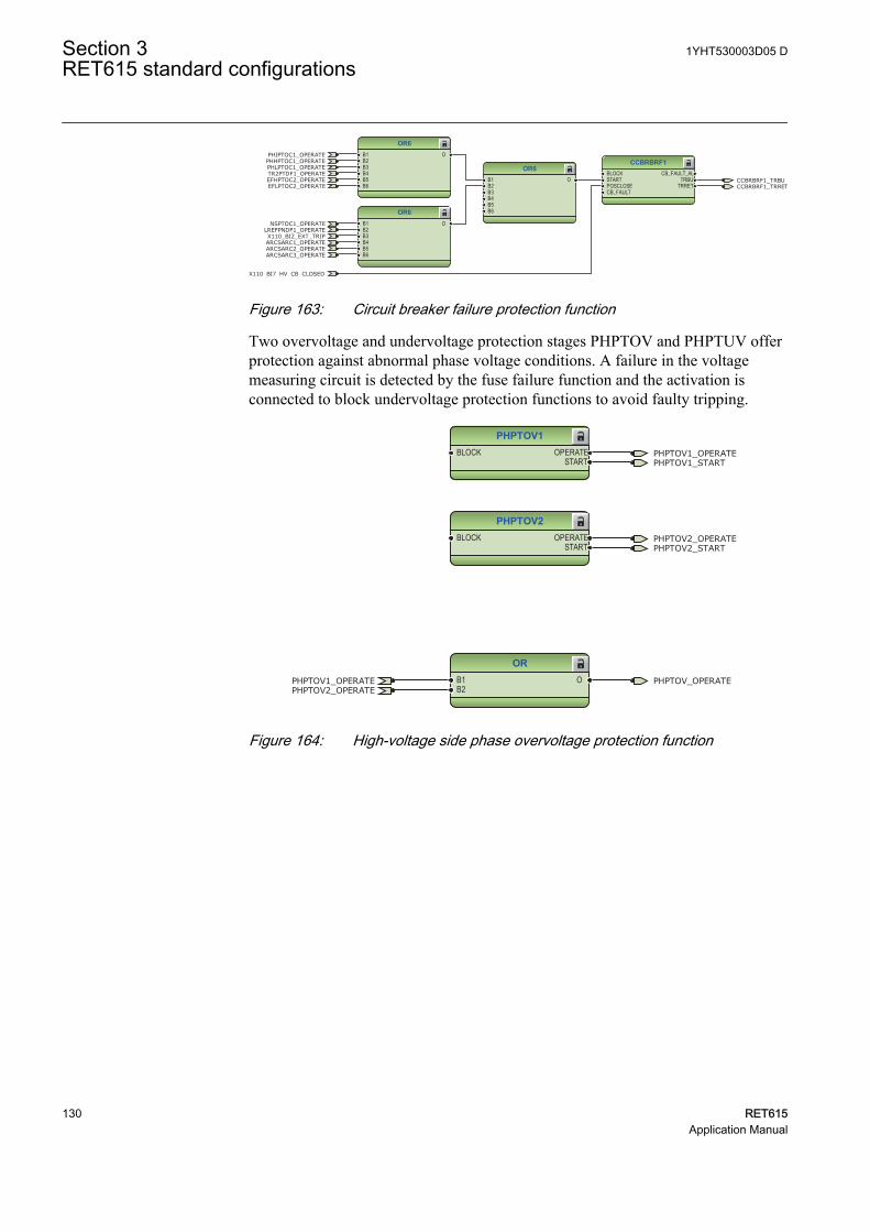
CCBRBRF1BLOCKSTARTPOSCLOSECB_FAULT
CB_FAULT_ALTRBU
TRRET
OR6B1B2B3B4B5B6
O
OR6B1B2B3B4B5B6
O
OR6B1B2B3B4B5B6
O CCBRBRF1_TRBU
X110_BI7_HV_CB_CLOSED
PHIPTOC1_OPERATE
PHLPTOC1_OPERATEPHHPTOC1_OPERATE
LREFPNDF1_OPERATE
CCBRBRF1_TRRET
NSPTOC1_OPERATE
TR2PTDF1_OPERATE
X110_BI2_EXT_TRIPARCSARC1_OPERATEARCSARC2_OPERATEARCSARC3_OPERATE
EFLPTOC2_OPERATEEFHPTOC2_OPERATE
GUID-8B8C1EBB-BF94-4711-BACD-D46394BA499F V1 EN
Figure 163: Circuit breaker failure protection function
Two overvoltage and undervoltage protection stages PHPTOV and PHPTUV offerprotection against abnormal phase voltage conditions. A failure in the voltagemeasuring circuit is detected by the fuse failure function and the activation isconnected to block undervoltage protection functions to avoid faulty tripping.
PHPTOV1BLOCK OPERATE
START
PHPTOV2BLOCK OPERATE
START
ORB1B2
O
PHPTOV1_OPERATE
PHPTOV1_OPERATE
PHPTOV2_OPERATE
PHPTOV2_OPERATE
PHPTOV1_START
PHPTOV2_START
PHPTOV_OPERATE
GUID-6A88AC93-826A-4C35-B48F-A50144C7B96B V1 EN
Figure 164: High-voltage side phase overvoltage protection function
Section 3 1YHT530003D05 DRET615 standard configurations
130 RET615Application Manual
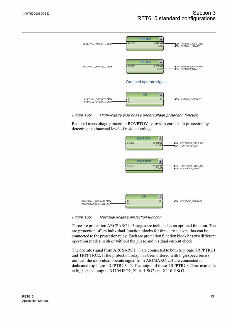
PHPTUV1BLOCK OPERATE
START
PHPTUV2BLOCK OPERATE
START
ORB1B2
O
PHPTUV1_OPERATE
PHPTUV1_OPERATE
PHPTUV2_OPERATE
PHPTUV2_OPERATE
PHPTUV1_START
PHPTUV2_START
SEQSPVC1_FUSEF_U
SEQSPVC1_FUSEF_U
PHPTUV_OPERATE
Grouped operate signal
GUID-FA480879-2BF2-44C9-81FD-B9C896868544 V2 EN
Figure 165: High-voltage side phase undervoltage protection function
Residual overvoltage protection ROVPTOV1 provides earth-fault protection bydetecting an abnormal level of residual voltage.
ROVPTOV1BLOCK OPERATE
START
ROVPTOV2BLOCK OPERATE
START
ORB1B2
O
ROVPTOV1_OPERATE
ROVPTOV1_OPERATE
ROVPTOV2_OPERATE
ROVPTOV2_OPERATE
ROVPTOV1_START
ROVPTOV2_START
ROVPTOV_OPERATE
GUID-81B3BF20-E20C-4B72-9BE8-F018BEB10DA2 V1 EN
Figure 166: Residual voltage protection function
Three arc protection ARCSARC1...3 stages are included as an optional function. Thearc protection offers individual function blocks for three arc sensors that can beconnected to the protection relay. Each arc protection function block has two differentoperation modes, with or without the phase and residual current check.
The operate signal from ARCSARC1...3 are connected to both trip logic TRPPTRC1and TRPPTRC2. If the protection relay has been ordered with high speed binaryoutputs, the individual operate signal from ARCSARC1...3 are connected todedicated trip logic TRPPTRC3...5. The output of these TRPPTRC3..5 are availableat high speed outputs X110:HSO1, X110:HSO2 and X110:HSO3.
1YHT530003D05 D Section 3RET615 standard configurations
RET615 131Application Manual

ARCSARC1BLOCKREM_FLT_ARCOPR_MODE
OPERATEARC_FLT_DET
ARCSARC2BLOCKREM_FLT_ARCOPR_MODE
OPERATEARC_FLT_DET
ARCSARC3BLOCKREM_FLT_ARCOPR_MODE
OPERATEARC_FLT_DET
OR6B1B2B3B4B5B6
O
ARCSARC1_OPERATE
ARCSARC1_OPERATE
ARCSARC2_OPERATE
ARCSARC2_OPERATE
ARCSARC3_OPERATE
ARCSARC3_OPERATE
ARCSARC1_ARC_FLT_DET
ARCSARC2_ARC_FLT_DET
ARCSARC3_ARC_FLT_DET
ARCSARC_OPERATE
GUID-277F17CE-3DBE-4E47-A2F5-65D19F6F14C5 V1 EN
TRPPTRC3BLOCKOPERATERST_LKOUT
TRIPCL_LKOUT
TRPPTRC4BLOCKOPERATERST_LKOUT
TRIPCL_LKOUT
TRPPTRC5BLOCKOPERATERST_LKOUT
TRIPCL_LKOUT
TRPPTRC3_TRIP
TRPPTRC4_TRIP
TRPPTRC5_TRIP
ARCSARC1_OPERATE
ARCSARC2_OPERATE
ARCSARC3_OPERATE
GUID-2A05AC92-C0D2-42A8-B3DA-262C026221EF V1 EN
Figure 167: Arc protection with dedicated HSO
Runtime counter for machines and devices MDSOPT1 accumulates the operationtime of the transformer.
Section 3 1YHT530003D05 DRET615 standard configurations
132 RET615Application Manual
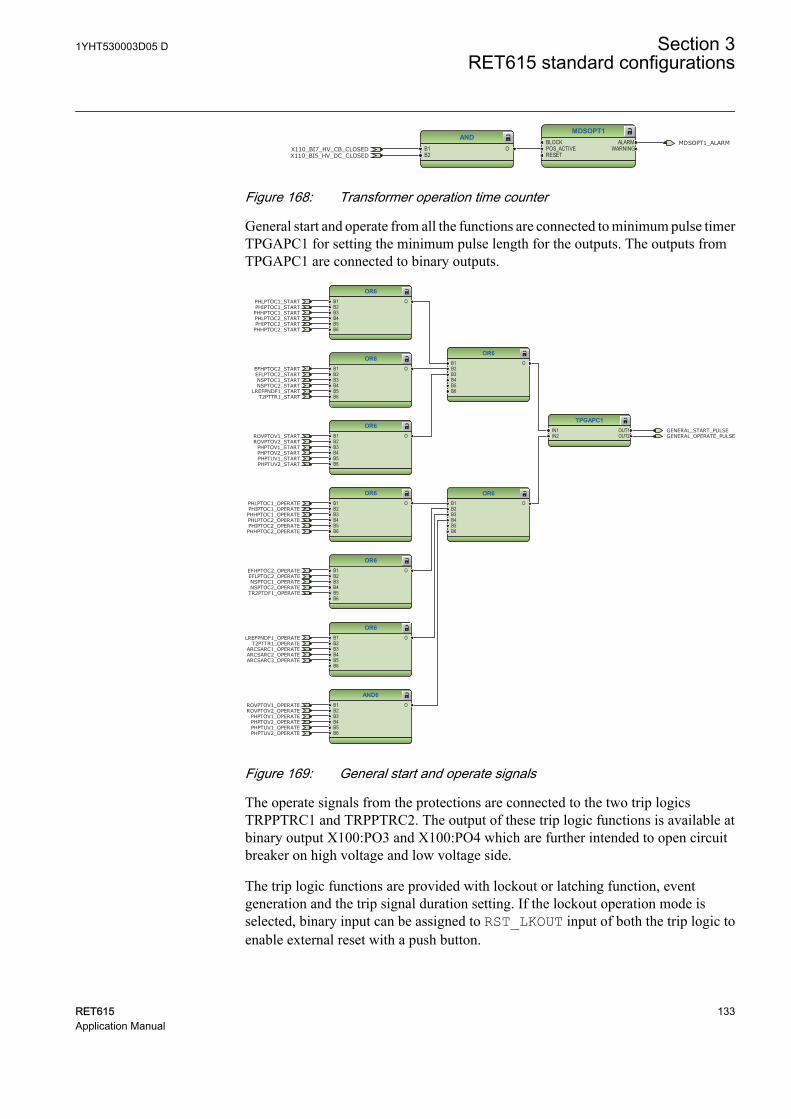
MDSOPT1BLOCKPOS_ACTIVERESET
ALARMWARNING
ANDB1B2
OX110_BI7_HV_CB_CLOSEDX110_BI5_HV_DC_CLOSED
MDSOPT1_ALARM
GUID-7D7E2CA4-6646-4576-BF7A-97A1C2EFAEF6 V1 EN
Figure 168: Transformer operation time counter
General start and operate from all the functions are connected to minimum pulse timerTPGAPC1 for setting the minimum pulse length for the outputs. The outputs fromTPGAPC1 are connected to binary outputs.
OR6B1B2B3B4B5B6
O
OR6B1B2B3B4B5B6
O
OR6B1B2B3B4B5B6
O
OR6B1B2B3B4B5B6
O
OR6B1B2B3B4B5B6
O
OR6B1B2B3B4B5B6
O
OR6B1B2B3B4B5B6
O
OR6B1B2B3B4B5B6
O
TPGAPC1IN1IN2
OUT1OUT2
AND6B1B2B3B4B5B6
O
GENERAL_START_PULSEGENERAL_OPERATE_PULSE
PHIPTOC1_OPERATEPHLPTOC1_OPERATE
PHHPTOC1_OPERATE
LREFPNDF1_OPERATE
NSPTOC1_OPERATE
TR2PTDF1_OPERATE
ARCSARC1_OPERATEARCSARC2_OPERATEARCSARC3_OPERATE
ROVPTOV1_OPERATEROVPTOV2_OPERATE
PHPTOV1_OPERATEPHPTOV2_OPERATEPHPTUV1_OPERATEPHPTUV2_OPERATE
PHIPTOC2_OPERATEPHLPTOC2_OPERATE
PHHPTOC2_OPERATE
T2PTTR1_OPERATE
NSPTOC2_OPERATE
EFLPTOC2_OPERATEEFHPTOC2_OPERATE
PHIPTOC1_STARTPHLPTOC1_START
PHHPTOC1_STARTPHLPTOC2_STARTPHIPTOC2_STARTPHHPTOC2_START
EFHPTOC2_STARTEFLPTOC2_STARTNSPTOC1_STARTNSPTOC2_START
LREFPNDF1_STARTT2PTTR1_START
ROVPTOV1_STARTROVPTOV2_START
PHPTOV1_STARTPHPTOV2_STARTPHPTUV1_STARTPHPTUV2_START
GUID-8668FA5A-4464-44A6-AE6A-76B1B31044D4 V1 EN
Figure 169: General start and operate signals
The operate signals from the protections are connected to the two trip logicsTRPPTRC1 and TRPPTRC2. The output of these trip logic functions is available atbinary output X100:PO3 and X100:PO4 which are further intended to open circuitbreaker on high voltage and low voltage side.
The trip logic functions are provided with lockout or latching function, eventgeneration and the trip signal duration setting. If the lockout operation mode isselected, binary input can be assigned to RST_LKOUT input of both the trip logic toenable external reset with a push button.
1YHT530003D05 D Section 3RET615 standard configurations
RET615 133Application Manual
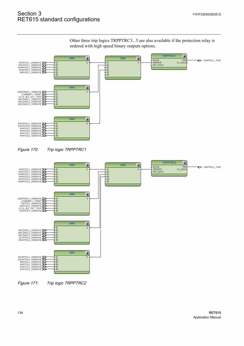
Other three trip logics TRPPTRC3...5 are also available if the protection relay isordered with high speed binary outputs options.
TRPPTRC1BLOCKOPERATERST_LKOUT
TRIPCL_LKOUT
OR6B1B2B3B4B5B6
O
OR6B1B2B3B4B5B6
O
OR6B1B2B3B4B5B6
O
OR6B1B2B3B4B5B6
O
TRPPTRC1_TRIPPHIPTOC1_OPERATEPHLPTOC1_OPERATEPHHPTOC1_OPERATE
LREFPNDF1_OPERATECCBRBRF1_TRRET
NSPTOC1_OPERATETR2PTDF1_OPERATE
X110_BI2_EXT_TRIPARCSARC1_OPERATEARCSARC2_OPERATEARCSARC3_OPERATE
ROVPTOV1_OPERATEROVPTOV2_OPERATE
PHPTOV1_OPERATEPHPTOV2_OPERATEPHPTUV1_OPERATEPHPTUV2_OPERATE
GUID-3C729D4A-DCD6-405C-9718-E6E67479D511 V1 EN
Figure 170: Trip logic TRPPTRC1
OR6B1B2B3B4B5B6
O
OR6B1B2B3B4B5B6
O
OR6B1B2B3B4B5B6
O
OR6B1B2B3B4B5B6
O
TRPPTRC2BLOCKOPERATERST_LKOUT
TRIPCL_LKOUT
OR6B1B2B3B4B5B6
O
TRPPTRC2_TRIPPHIPTOC1_OPERATEPHLPTOC1_OPERATEPHHPTOC1_OPERATE
LREFPNDF1_OPERATECCBRBRF1_TRRET
TR2PTDF1_OPERATEX110_BI2_EXT_TRIP
ARCSARC1_OPERATEARCSARC2_OPERATEARCSARC3_OPERATE
ROVPTOV1_OPERATEROVPTOV2_OPERATE
PHPTOV1_OPERATEPHPTOV2_OPERATEPHPTUV1_OPERATEPHPTUV2_OPERATE
PHIPTOC2_OPERATEPHLPTOC2_OPERATEPHHPTOC2_OPERATE
T2PTTR1_OPERATENSPTOC2_OPERATE
EFLPTOC2_OPERATEEFHPTOC2_OPERATE
GUID-376FDA9B-00B1-4D80-9FEE-D74C6481164A V1 EN
Figure 171: Trip logic TRPPTRC2
Section 3 1YHT530003D05 DRET615 standard configurations
134 RET615Application Manual
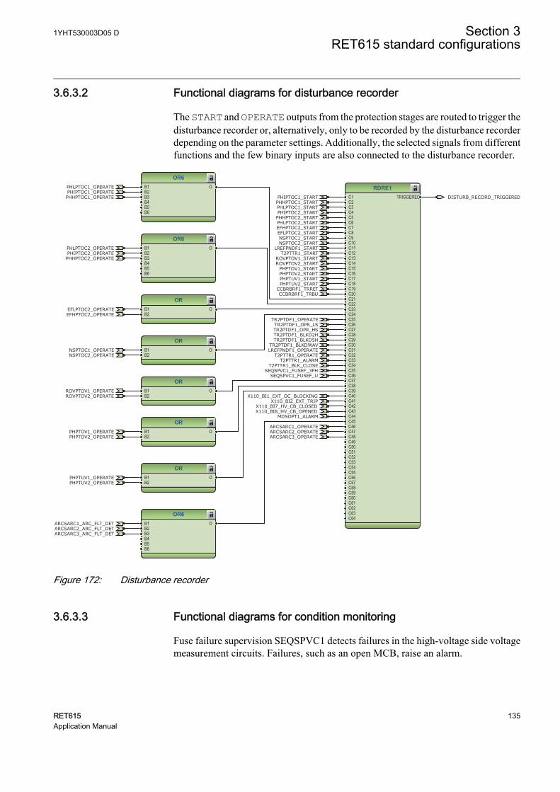
3.6.3.2 Functional diagrams for disturbance recorder
The START and OPERATE outputs from the protection stages are routed to trigger thedisturbance recorder or, alternatively, only to be recorded by the disturbance recorderdepending on the parameter settings. Additionally, the selected signals from differentfunctions and the few binary inputs are also connected to the disturbance recorder.
RDRE1C1C2C3C4C5C6C7C8C9C10C11C12C13C14C15C16C17C18C19C20C21C22C23C24C25C26C27C28C29C30C31C32C33C34C35C36C37C38C39C40C41C42C43C44C45C46C47C48C49C50C51C52C53C54C55C56C57C58C59C60C61C62C63C64
TRIGGERED
OR6B1B2B3B4B5B6
O
ORB1B2
O
ORB1B2
O
OR6B1B2B3B4B5B6
O
OR6B1B2B3B4B5B6
O
ORB1B2
O
ORB1B2
O
ORB1B2
O
CCBRBRF1_TRBU
X110_BI8_HV_CB_OPENEDX110_BI7_HV_CB_CLOSED
PHIPTOC1_OPERATEPHLPTOC1_OPERATE
PHHPTOC1_OPERATE
LREFPNDF1_OPERATE
CCBRBRF1_TRRET
NSPTOC1_OPERATE
X110_BI2_EXT_TRIP
ARCSARC1_OPERATEARCSARC2_OPERATEARCSARC3_OPERATE
ROVPTOV1_OPERATEROVPTOV2_OPERATE
PHPTOV1_OPERATEPHPTOV2_OPERATE
PHPTUV1_OPERATEPHPTUV2_OPERATE
TR2PTDF1_OPERATE
PHIPTOC2_OPERATEPHLPTOC2_OPERATE
PHHPTOC2_OPERATE
T2PTTR1_OPERATENSPTOC2_OPERATE
EFLPTOC2_OPERATEEFHPTOC2_OPERATE
PHIPTOC1_START
PHLPTOC1_STARTPHHPTOC1_START
PHLPTOC2_START
PHIPTOC2_STARTPHHPTOC2_START
EFHPTOC2_STARTEFLPTOC2_STARTNSPTOC1_STARTNSPTOC2_START
LREFPNDF1_STARTT2PTTR1_START
ROVPTOV1_STARTROVPTOV2_START
PHPTOV1_STARTPHPTOV2_STARTPHPTUV1_STARTPHPTUV2_START
X110_BI1_EXT_OC_BLOCKING
SEQSPVC1_FUSEF_U
ARCSARC1_ARC_FLT_DETARCSARC2_ARC_FLT_DETARCSARC3_ARC_FLT_DET
T2PTTR1_ALARMT2PTTR1_BLK_CLOSE
SEQSPVC1_FUSEF_3PH
MDSOPT1_ALARM
TR2PTDF1_OPR_LSTR2PTDF1_OPR_HSTR2PTDF1_BLKD2HTR2PTDF1_BLKD5H
TR2PTDF1_BLKDWAV
DISTURB_RECORD_TRIGGERED
GUID-5B9C595C-C7AF-4847-81F4-9999117A519E V2 EN
Figure 172: Disturbance recorder
3.6.3.3 Functional diagrams for condition monitoring
Fuse failure supervision SEQSPVC1 detects failures in the high-voltage side voltagemeasurement circuits. Failures, such as an open MCB, raise an alarm.
1YHT530003D05 D Section 3RET615 standard configurations
RET615 135Application Manual
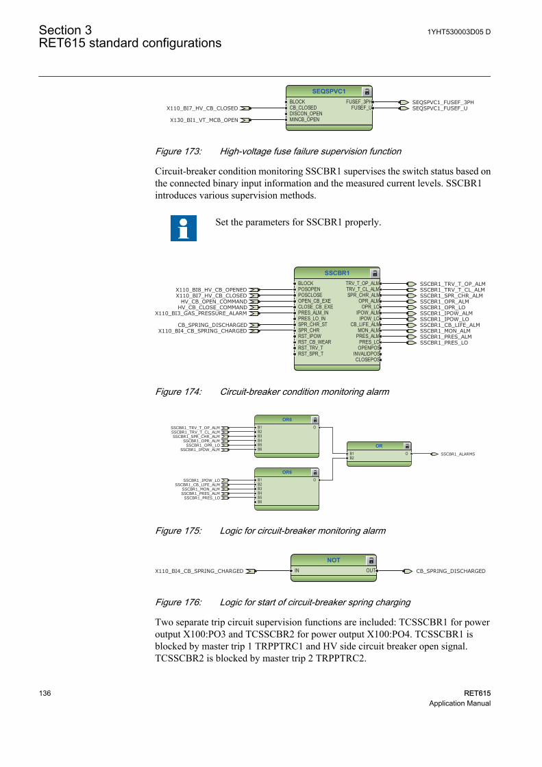
SEQSPVC1BLOCKCB_CLOSEDDISCON_OPENMINCB_OPEN
FUSEF_3PHFUSEF_UX110_BI7_HV_CB_CLOSED SEQSPVC1_FUSEF_U
X130_BI1_VT_MCB_OPEN
SEQSPVC1_FUSEF_3PH
GUID-B79640FE-EB2A-4EB1-9BCF-FC61E00ECADA V2 EN
Figure 173: High-voltage fuse failure supervision function
Circuit-breaker condition monitoring SSCBR1 supervises the switch status based onthe connected binary input information and the measured current levels. SSCBR1introduces various supervision methods.
Set the parameters for SSCBR1 properly.
SSCBR1BLOCKPOSOPENPOSCLOSEOPEN_CB_EXECLOSE_CB_EXEPRES_ALM_INPRES_LO_INSPR_CHR_STSPR_CHRRST_IPOWRST_CB_WEARRST_TRV_TRST_SPR_T
TRV_T_OP_ALMTRV_T_CL_ALMSPR_CHR_ALM
OPR_ALMOPR_LO
IPOW_ALMIPOW_LO
CB_LIFE_ALMMON_ALM
PRES_ALMPRES_LO
OPENPOSINVALIDPOSCLOSEPOS
HV_CB_CLOSE_COMMANDHV_CB_OPEN_COMMAND
X110_BI8_HV_CB_OPENEDX110_BI7_HV_CB_CLOSED
X110_BI3_GAS_PRESSURE_ALARM
X110_BI4_CB_SPRING_CHARGEDCB_SPRING_DISCHARGED
SSCBR1_TRV_T_OP_ALMSSCBR1_TRV_T_CL_ALMSSCBR1_SPR_CHR_ALMSSCBR1_OPR_ALMSSCBR1_OPR_LOSSCBR1_IPOW_ALMSSCBR1_IPOW_LOSSCBR1_CB_LIFE_ALMSSCBR1_MON_ALMSSCBR1_PRES_ALMSSCBR1_PRES_LO
GUID-15E9E109-F8EC-4C0A-9713-4C2BBC3DC2FC V1 EN
Figure 174: Circuit-breaker condition monitoring alarm
OR6B1B2B3B4B5B6
O
OR6B1B2B3B4B5B6
O
ORB1B2
O
SSCBR1_TRV_T_OP_ALMSSCBR1_TRV_T_CL_ALMSSCBR1_SPR_CHR_ALM
SSCBR1_OPR_ALMSSCBR1_OPR_LO
SSCBR1_IPOW_ALM
SSCBR1_IPOW_LOSSCBR1_CB_LIFE_ALM
SSCBR1_MON_ALMSSCBR1_PRES_ALM
SSCBR1_PRES_LO
SSCBR1_ALARMS
GUID-EA946008-6F99-414E-925B-E01751A70C3B V1 EN
Figure 175: Logic for circuit-breaker monitoring alarm
NOTIN OUTX110_BI4_CB_SPRING_CHARGED CB_SPRING_DISCHARGED
GUID-B40AF2D9-3405-43B8-91D2-8FDF5F494F78 V1 EN
Figure 176: Logic for start of circuit-breaker spring charging
Two separate trip circuit supervision functions are included: TCSSCBR1 for poweroutput X100:PO3 and TCSSCBR2 for power output X100:PO4. TCSSCBR1 isblocked by master trip 1 TRPPTRC1 and HV side circuit breaker open signal.TCSSCBR2 is blocked by master trip 2 TRPPTRC2.
Section 3 1YHT530003D05 DRET615 standard configurations
136 RET615Application Manual
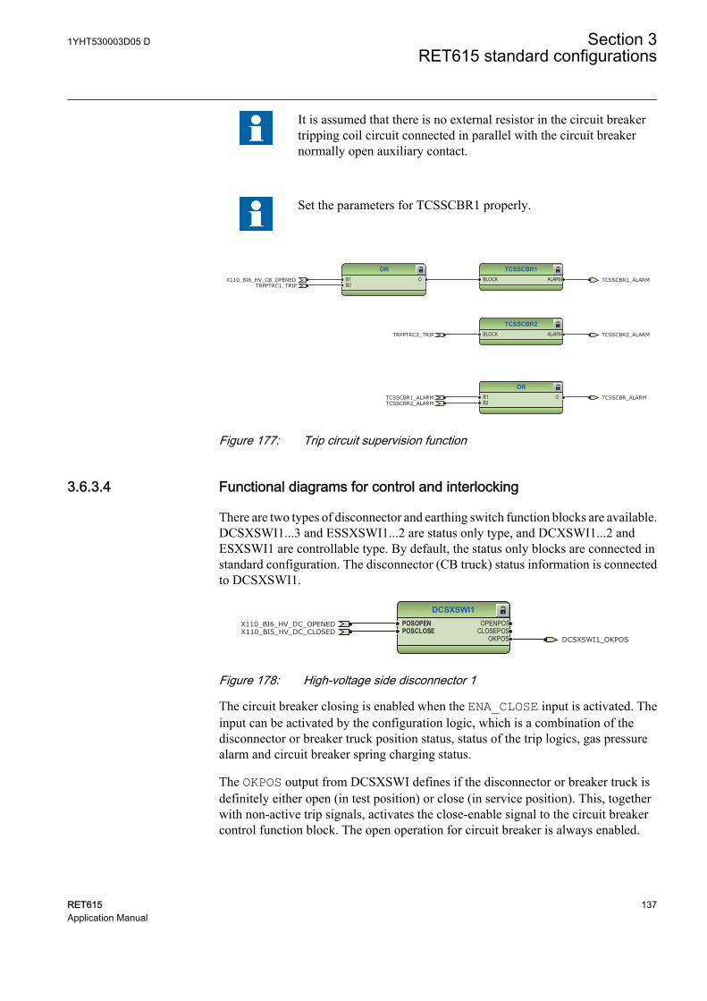
It is assumed that there is no external resistor in the circuit breakertripping coil circuit connected in parallel with the circuit breakernormally open auxiliary contact.
Set the parameters for TCSSCBR1 properly.
ORB1B2
OTCSSCBR1_ALARMTCSSCBR2_ALARM
TCSSCBR_ALARM
TCSSCBR1BLOCK ALARM
ORB1B2
OTRPPTRC1_TRIP
X110_BI8_HV_CB_OPENED TCSSCBR1_ALARM
TCSSCBR2BLOCK ALARMTRPPTRC2_TRIP TCSSCBR2_ALARM
GUID-FB71DD76-698D-4117-873C-6730CD2121DD V1 EN
Figure 177: Trip circuit supervision function
3.6.3.4 Functional diagrams for control and interlocking
There are two types of disconnector and earthing switch function blocks are available.DCSXSWI1...3 and ESSXSWI1...2 are status only type, and DCXSWI1...2 andESXSWI1 are controllable type. By default, the status only blocks are connected instandard configuration. The disconnector (CB truck) status information is connectedto DCSXSWI1.
DCSXSWI1POSOPENPOSCLOSE
OPENPOSCLOSEPOS
OKPOS DCSXSWI1_OKPOS
X110_BI6_HV_DC_OPENEDX110_BI5_HV_DC_CLOSED
GUID-120781E2-F581-4DD3-AB66-FCC8585D3470 V1 EN
Figure 178: High-voltage side disconnector 1
The circuit breaker closing is enabled when the ENA_CLOSE input is activated. Theinput can be activated by the configuration logic, which is a combination of thedisconnector or breaker truck position status, status of the trip logics, gas pressurealarm and circuit breaker spring charging status.
The OKPOS output from DCSXSWI defines if the disconnector or breaker truck isdefinitely either open (in test position) or close (in service position). This, togetherwith non-active trip signals, activates the close-enable signal to the circuit breakercontrol function block. The open operation for circuit breaker is always enabled.
1YHT530003D05 D Section 3RET615 standard configurations
RET615 137Application Manual
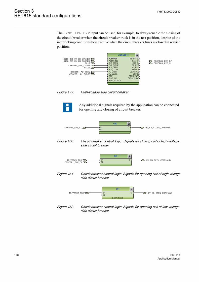
The SYNC_ITL_BYP input can be used, for example, to always enable the closing ofthe circuit breaker when the circuit breaker truck is in the test position, despite of theinterlocking conditions being active when the circuit breaker truck is closed in serviceposition.
CBXCBR1POSOPENPOSCLOSEENA_OPENENA_CLOSEBLK_OPENBLK_CLOSEAU_OPENAU_CLOSETRIPSYNC_OKSYNC_ITL_BYP
SELECTEDEXE_OPEXE_CL
OP_REQCL_REQ
OPENPOSCLOSEPOS
OKPOSOPEN_ENAD
CLOSE_ENAD
TRUECBXCBR1_EXE_OPCBXCBR1_EXE_CL
FALSE
X110_BI8_HV_CB_OPENEDX110_BI7_HV_CB_CLOSED
CBXCBR1_ENA_CLOSE
CBXCBR1_AU_OPENCBXCBR1_AU_CLOSE
GUID-553A4478-56AA-48C4-8FAE-3F87FFA43E59 V2 EN
Figure 179: High-voltage side circuit breaker
Any additional signals required by the application can be connectedfor opening and closing of circuit breaker.
ORB1B2
O HV_CB_CLOSE_COMMANDCBXCBR1_EXE_CL
GUID-36CF4F1A-4C7F-493A-9BAD-1ACCD4E43877 V1 EN
Figure 180: Circuit breaker control logic: Signals for closing coil of high-voltageside circuit breaker
ORB1B2
O HV_CB_OPEN_COMMANDTRPPTRC1_TRIPCBXCBR1_EXE_OP
GUID-C34FF724-B57C-4EF9-B0CE-09CFB4B94604 V1 EN
Figure 181: Circuit breaker control logic: Signals for opening coil of high-voltageside circuit breaker
OR
O:80|T:2.5|I:8
B1B2
O LV_CB_OPEN_COMMANDTRPPTRC2_TRIP
GUID-622093B1-7302-4FE5-AFA2-33A018724DD0 V1 EN
Figure 182: Circuit breaker control logic: Signals for opening coil of low-voltageside circuit breaker
Section 3 1YHT530003D05 DRET615 standard configurations
138 RET615Application Manual
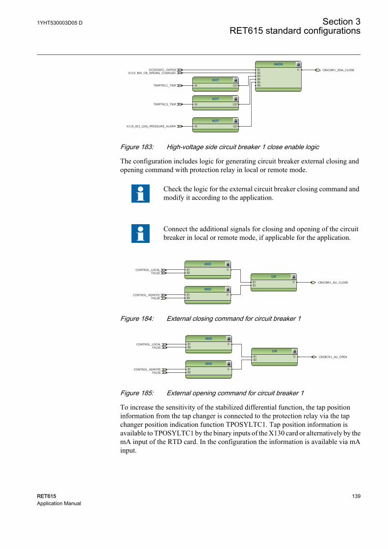
NOTIN OUT
AND6B1B2B3B4B5B6
O
NOTIN OUT
NOTIN OUT
TRPPTRC1_TRIP
CBXCBR1_ENA_CLOSE
X110_BI3_GAS_PRESSURE_ALARM
TRPPTRC2_TRIP
DCSXSWI1_OKPOSX110_BI4_CB_SPRING_CHARGED
GUID-3A59DE6F-D384-495B-B71C-6FD50A61EE38 V1 EN
Figure 183: High-voltage side circuit breaker 1 close enable logic
The configuration includes logic for generating circuit breaker external closing andopening command with protection relay in local or remote mode.
Check the logic for the external circuit breaker closing command andmodify it according to the application.
Connect the additional signals for closing and opening of the circuitbreaker in local or remote mode, if applicable for the application.
ANDB1B2
O
ANDB1B2
O
ORB1B2
O CBXCBR1_AU_CLOSE
CONTROL_LOCAL
CONTROL_REMOTE
FALSE
FALSE
GUID-137B21F6-4F25-4D4F-B102-A3CFC39C2343 V1 EN
Figure 184: External closing command for circuit breaker 1
ANDB1B2
O
ORB1B2
O
ANDB1B2
O
CBXBCR1_AU_OPEN
CONTROL_LOCAL
CONTROL_REMOTE
FALSE
FALSE
GUID-92F41E20-6362-4212-A65A-FB1046C4751F V1 EN
Figure 185: External opening command for circuit breaker 1
To increase the sensitivity of the stabilized differential function, the tap positioninformation from the tap changer is connected to the protection relay via the tapchanger position indication function TPOSYLTC1. Tap position information isavailable to TPOSYLTC1 by the binary inputs of the X130 card or alternatively by themA input of the RTD card. In the configuration the information is available via mAinput.
1YHT530003D05 D Section 3RET615 standard configurations
RET615 139Application Manual
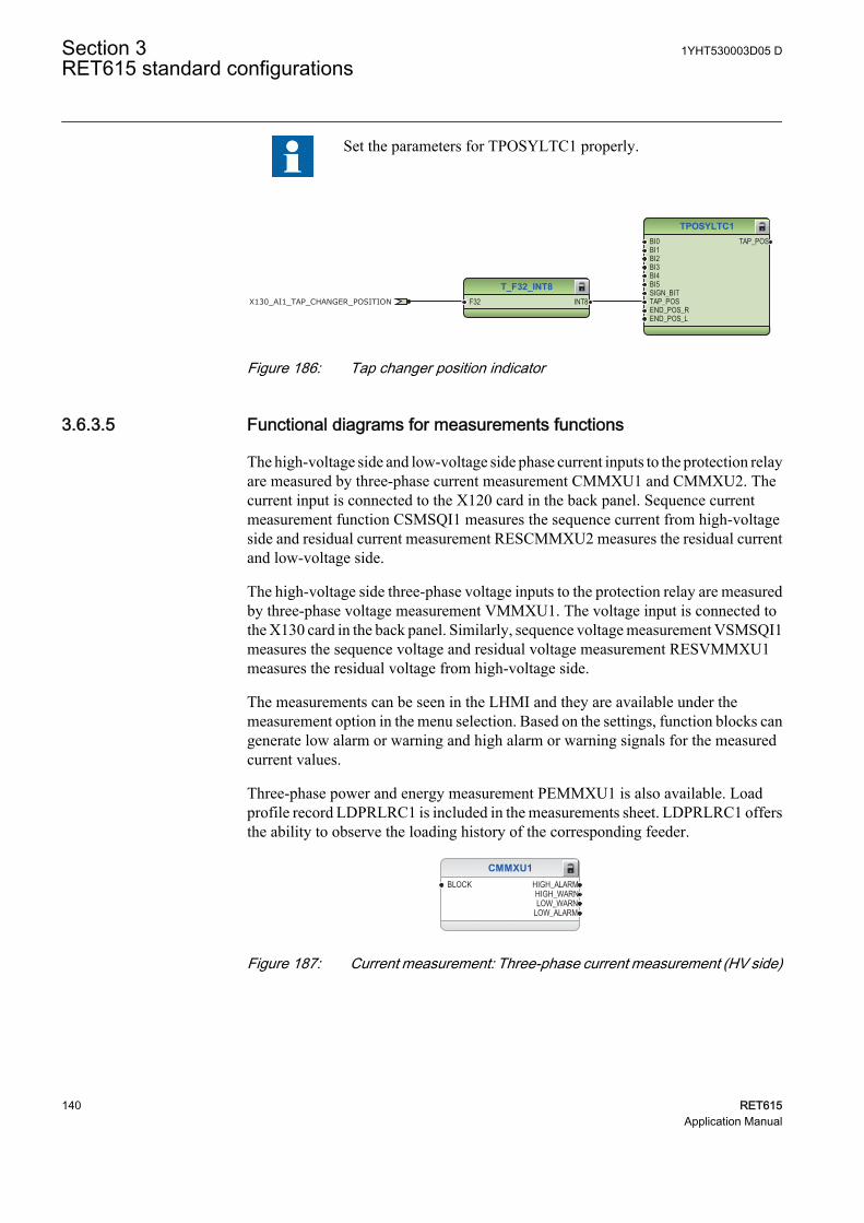
Set the parameters for TPOSYLTC1 properly.
TPOSYLTC1BI0BI1BI2BI3BI4BI5SIGN_BITTAP_POSEND_POS_REND_POS_L
TAP_POS
T_F32_INT8F32 INT8X130_AI1_TAP_CHANGER_POSITION
GUID-EF6DA5D1-F516-4C21-B06B-D7015A7B89C9 V2 EN
Figure 186: Tap changer position indicator
3.6.3.5 Functional diagrams for measurements functions
The high-voltage side and low-voltage side phase current inputs to the protection relayare measured by three-phase current measurement CMMXU1 and CMMXU2. Thecurrent input is connected to the X120 card in the back panel. Sequence currentmeasurement function CSMSQI1 measures the sequence current from high-voltageside and residual current measurement RESCMMXU2 measures the residual currentand low-voltage side.
The high-voltage side three-phase voltage inputs to the protection relay are measuredby three-phase voltage measurement VMMXU1. The voltage input is connected tothe X130 card in the back panel. Similarly, sequence voltage measurement VSMSQI1measures the sequence voltage and residual voltage measurement RESVMMXU1measures the residual voltage from high-voltage side.
The measurements can be seen in the LHMI and they are available under themeasurement option in the menu selection. Based on the settings, function blocks cangenerate low alarm or warning and high alarm or warning signals for the measuredcurrent values.
Three-phase power and energy measurement PEMMXU1 is also available. Loadprofile record LDPRLRC1 is included in the measurements sheet. LDPRLRC1 offersthe ability to observe the loading history of the corresponding feeder.
CMMXU1BLOCK HIGH_ALARM
HIGH_WARNLOW_WARN
LOW_ALARM
GUID-F4E55333-152F-4AEF-8CAC-03B6169AE181 V1 EN
Figure 187: Current measurement: Three-phase current measurement (HV side)
Section 3 1YHT530003D05 DRET615 standard configurations
140 RET615Application Manual

CMMXU2BLOCK HIGH_ALARM
HIGH_WARNLOW_WARN
LOW_ALARM
GUID-87EDF286-2B13-479F-BFD5-6F766952936D V1 EN
Figure 188: Current measurement: Three-phase current measurement (LV side)
CSMSQI1
GUID-27E9BB6C-371B-4385-B39A-0CB282139753 V1 EN
Figure 189: Current measurement: Sequence current measurement (HV side)
RESCMMXU2BLOCK HIGH_ALARM
HIGH_WARN
GUID-67951DDA-A6AE-4AFA-9F01-C489CB568463 V1 EN
Figure 190: Current measurement: Residual current measurement (LV side)
VMMXU1BLOCK HIGH_ALARM
HIGH_WARNLOW_WARN
LOW_ALARM
GUID-B718ADA0-C6C1-4BCE-AF13-D97C9543C6C4 V1 EN
Figure 191: Voltage measurement: Three-phase voltage measurement (HV side)
VSMSQI1
GUID-952B15EE-B2D1-43EE-9FF7-696919A4A150 V1 EN
Figure 192: Voltage measurement: Sequence voltage measurement (HV side)
RESVMMXU1BLOCK HIGH_ALARM
HIGH_WARN
GUID-0148F4DD-D1A5-44EF-A200-01BDF3D431F5 V1 EN
Figure 193: Voltage measurement: Residual voltage measurement (HV side)
FMMXU1
O:156|T:5|I:1GUID-7092F819-0E26-431B-A4EC-8C76493D1E73 V1 EN
Figure 194: Other measurement: Frequency measurement
1YHT530003D05 D Section 3RET615 standard configurations
RET615 141Application Manual
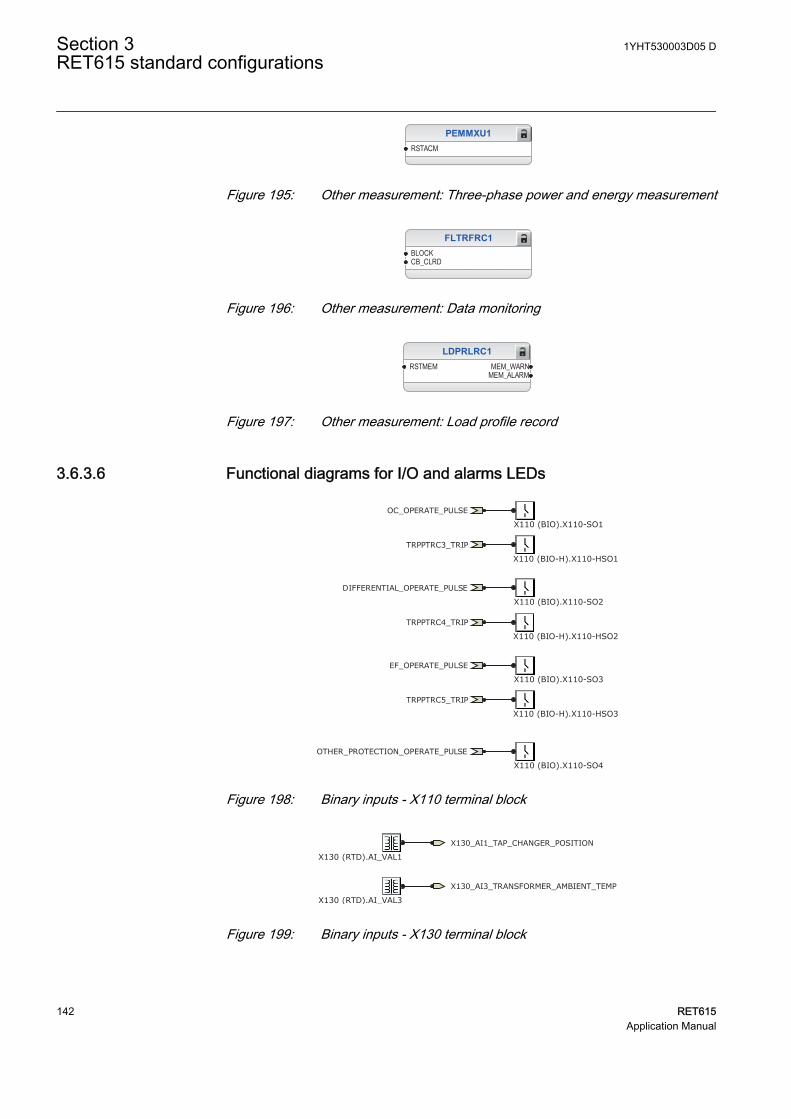
PEMMXU1RSTACM
GUID-4A0A8447-88D3-41B8-AEBC-8C3F1E733E62 V1 EN
Figure 195: Other measurement: Three-phase power and energy measurement
FLTRFRC1BLOCKCB_CLRD
GUID-45CCEB8A-1E17-4421-9564-A22A2BC9F68B V2 EN
Figure 196: Other measurement: Data monitoring
LDPRLRC1RSTMEM MEM_WARN
MEM_ALARM
GUID-03006A20-8E86-4FFE-BD85-2CE4A7F7A98A V2 EN
Figure 197: Other measurement: Load profile record
3.6.3.6 Functional diagrams for I/O and alarms LEDs
OC_OPERATE_PULSE
DIFFERENTIAL_OPERATE_PULSE
EF_OPERATE_PULSE
OTHER_PROTECTION_OPERATE_PULSE
TRPPTRC3_TRIP
TRPPTRC4_TRIP
TRPPTRC5_TRIP
X110 (BIO).X110-SO1
X110 (BIO).X110-SO2
X110 (BIO).X110-SO4
X110 (BIO).X110-SO3
X110 (BIO-H).X110-HSO1
X110 (BIO-H).X110-HSO2
X110 (BIO-H).X110-HSO3
GUID-E7140E5C-9A03-43CB-BAC4-7C006D3DCEB6 V1 EN
Figure 198: Binary inputs - X110 terminal block
X130_AI1_TAP_CHANGER_POSITION
X130 (RTD).AI_VAL1
X130_AI3_TRANSFORMER_AMBIENT_TEMP
X130 (RTD).AI_VAL3GUID-B1590618-BABA-42FE-AEB8-DE3E67614DD8 V1 EN
Figure 199: Binary inputs - X130 terminal block
Section 3 1YHT530003D05 DRET615 standard configurations
142 RET615Application Manual
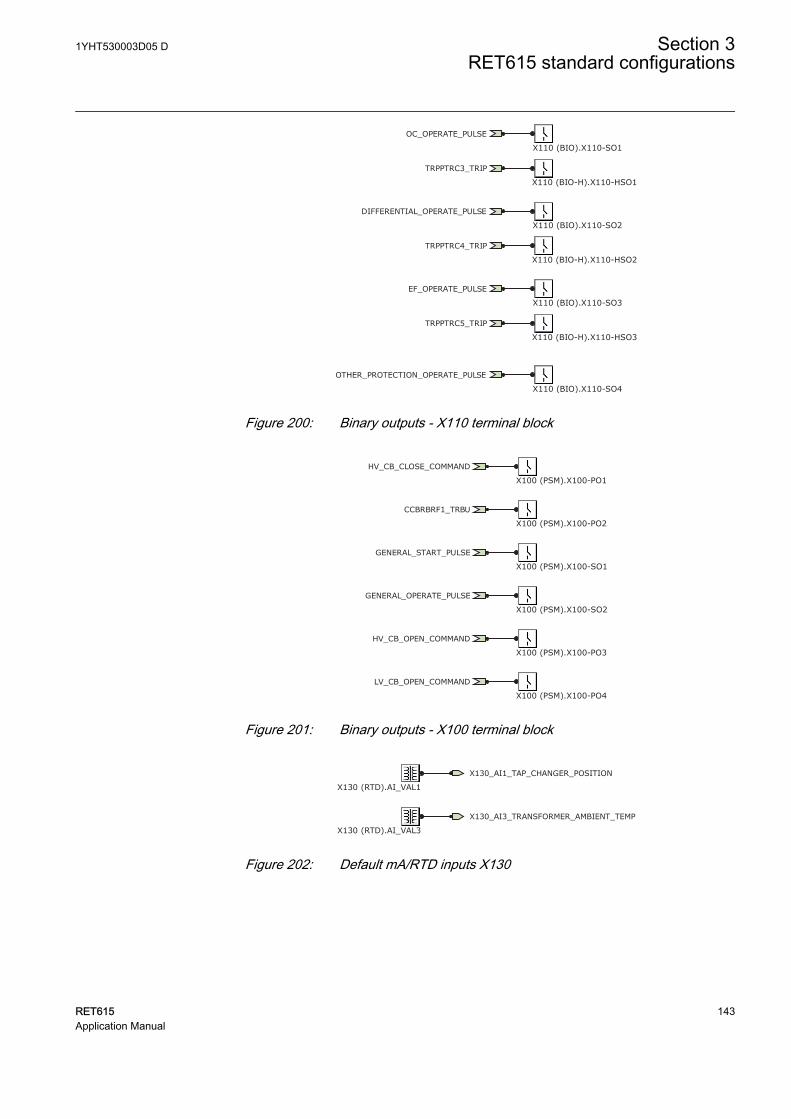
OC_OPERATE_PULSE
DIFFERENTIAL_OPERATE_PULSE
EF_OPERATE_PULSE
OTHER_PROTECTION_OPERATE_PULSE
TRPPTRC3_TRIP
TRPPTRC4_TRIP
TRPPTRC5_TRIP
X110 (BIO).X110-SO1
X110 (BIO).X110-SO2
X110 (BIO).X110-SO4
X110 (BIO).X110-SO3
X110 (BIO-H).X110-HSO1
X110 (BIO-H).X110-HSO2
X110 (BIO-H).X110-HSO3
GUID-56CF77CF-F752-4DBE-8F66-C13E810D643C V1 EN
Figure 200: Binary outputs - X110 terminal block
GENERAL_START_PULSE
GENERAL_OPERATE_PULSE
LV_CB_OPEN_COMMAND
CCBRBRF1_TRBU
HV_CB_CLOSE_COMMAND
HV_CB_OPEN_COMMAND
X100 (PSM).X100-PO1
X100 (PSM).X100-PO2
X100 (PSM).X100-SO1
X100 (PSM).X100-SO2
X100 (PSM).X100-PO3
X100 (PSM).X100-PO4GUID-523744FB-6407-466F-BE79-DEAA8E4DCFAB V1 EN
Figure 201: Binary outputs - X100 terminal block
X130_AI1_TAP_CHANGER_POSITION
X130 (RTD).AI_VAL1
X130_AI3_TRANSFORMER_AMBIENT_TEMP
X130 (RTD).AI_VAL3GUID-085B5001-69DA-4E82-884F-17D071CF7F1A V1 EN
Figure 202: Default mA/RTD inputs X130
1YHT530003D05 D Section 3RET615 standard configurations
RET615 143Application Manual
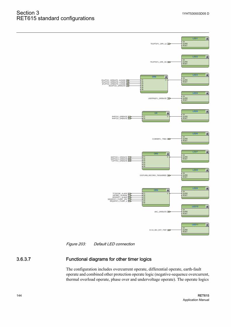
LED1OKALARMRESET
LED2OKALARMRESET
LED3OKALARMRESET
LED4OKALARMRESET
LED5OKALARMRESET
OR6B1B2B3B4B5B6
O
ORB1B2
O
LREFPNDF1_OPERATE
EFxPTOC_OPERATE_LVSIDEROVPTOV_OPERATE
PHPTOV_OPERATEPHPTUV_OPERATE
PHxPTOC_OPERATE_HVSIDEPHxPTOC_OPERATE_LVSIDE
TR2PTDF1_OPR_LS
TR2PTDF1_OPR_HS
GUID-AEE25172-B039-425B-A59E-6CB0D06A2E91 V2 EN
LED6OKALARMRESET
LED7OKALARMRESET
LED8OKALARMRESET
LED9OKALARMRESET
LED10OKALARMRESET
LED11OKALARMRESET
OR6B1B2B3B4B5B6
O
OR6B1B2B3B4B5B6
O
CCBRBRF1_TRBU
NSPTOC1_OPERATE
X110_BI2_EXT_TRIP
T2PTTR1_OPERATENSPTOC2_OPERATE
SEQSPVC1_FUSEF_USEQSPVC1_FUSEF_3PH
MDSOPT1_ALARM
ARC_OPERATE
TCSSCBR_ALARMSSCBR1_ALARMS
DISTURB_RECORD_TRIGGERED
GUID-8487FCAB-C8A5-49C1-A1FD-0B20613CC7CF V2 EN
Figure 203: Default LED connection
3.6.3.7 Functional diagrams for other timer logics
The configuration includes overcurrent operate, differential operate, earth-faultoperate and combined other protection operate logic (negative-sequence overcurrent,thermal overload operate, phase over and undervoltage operate). The operate logics
Section 3 1YHT530003D05 DRET615 standard configurations
144 RET615Application Manual
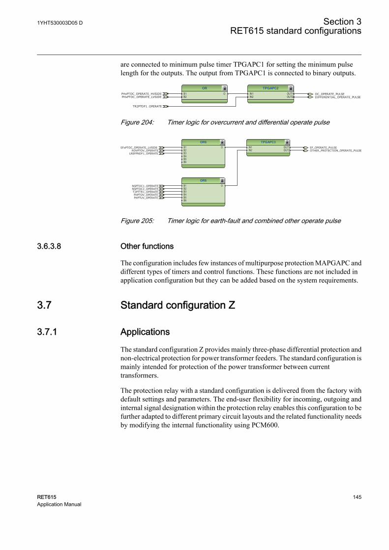
are connected to minimum pulse timer TPGAPC1 for setting the minimum pulselength for the outputs. The output from TPGAPC1 is connected to binary outputs.
TPGAPC2IN1IN2
OUT1OUT2
ORB1B2
O OC_OPERATE_PULSEDIFFERENTIAL_OPERATE_PULSE
TR2PTDF1_OPERATE
PHxPTOC_OPERATE_HVSIDEPHxPTOC_OPERATE_LVSIDE
GUID-857FAEAC-2498-4886-9CDA-E9F1016549A0 V1 EN
Figure 204: Timer logic for overcurrent and differential operate pulse
TPGAPC3IN1IN2
OUT1OUT2
OR6B1B2B3B4B5B6
O
OR6B1B2B3B4B5B6
O
EF_OPERATE_PULSEOTHER_PROTECTION_OPERATE_PULSE
LREFPNDF1_OPERATE
NSPTOC1_OPERATE
T2PTTR1_OPERATENSPTOC2_OPERATE
EFxPTOC_OPERATE_LVSIDEROVPTOV_OPERATE
PHPTOV_OPERATEPHPTUV_OPERATE
GUID-E9A63DFE-E2BB-432B-9C1C-4DD39ECC2FD3 V1 EN
Figure 205: Timer logic for earth-fault and combined other operate pulse
3.6.3.8 Other functions
The configuration includes few instances of multipurpose protection MAPGAPC anddifferent types of timers and control functions. These functions are not included inapplication configuration but they can be added based on the system requirements.
3.7 Standard configuration Z
3.7.1 Applications
The standard configuration Z provides mainly three-phase differential protection andnon-electrical protection for power transformer feeders. The standard configuration ismainly intended for protection of the power transformer between currenttransformers.
The protection relay with a standard configuration is delivered from the factory withdefault settings and parameters. The end-user flexibility for incoming, outgoing andinternal signal designation within the protection relay enables this configuration to befurther adapted to different primary circuit layouts and the related functionality needsby modifying the internal functionality using PCM600.
1YHT530003D05 D Section 3RET615 standard configurations
RET615 145Application Manual
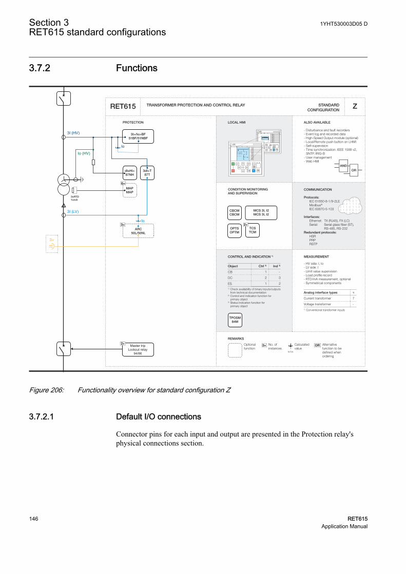
3.7.2 Functions
Master tripLockout relay
94/86
CONDITION MONITORING AND SUPERVISION
ALSO AVAILABLE
- Disturbance and fault recorders- Event log and recorded data- High-Speed Output module (optional)- Local/Remote push button on LHMI- Self-supervision- Time synchronization: IEEE 1588 v2,
SNTP, IRIG-B- User management- Web HMI
ORAND
CONTROL AND INDICATION 1) MEASUREMENT
TRANSFORMER PROTECTION AND CONTROL RELAY
PROTECTION LOCAL HMI
Object Ctrl 2) Ind 3)
CB
DC
ES1) Check availability of binary inputs/outputs
from technical documentation2) Control and indication function for
primary object3) Status indication function for primary object
1 -
2 3
1 2
STANDARD CONFIGURATION
REMARKS
Optionalfunction
No. ofinstances
Alternative function to be defined when ordering
OR
Io/Uo
Calculatedvalue
3×
RL
ClearESCI
O
Configuration ASystemHMITimeAuthorization
RL
ClearESCI
O
U12 0. 0 kVP 0.00 kWQ 0.00 kVAr
IL2 0 A
A
COMMUNICATION
Protocols: IEC 61850-8-1/9-2LE Modbus®
IEC 60870-5-103 Interfaces: Ethernet: TX (RJ45), FX (LC) Serial: Serial glass fiber (ST), RS-485, RS-232Redundant protocols: HSR PRP RSTP
RET615 Z
Analog interface types 1)
Current transformer
1) Conventional transformer inputs
Voltage transformer
7
-
- HV side: I, Io- LV side: I- Limit value supervision- Load profile record- RTD/mA measurement, optional- Symmetrical components
MCS 3I, I2MCS 3I, I2
3I>/Io>BF51BF/51NBF
3dI>T87T
3×ARC
50L/50NL
dIoHi>87NH
2×TCSTCM
CBCMCBCM
OPTSOPTM
TPOSM84M
3I (LV)
Io
Io
3×
3I (HV)
6×
MAPMAP
2xRTD1xmA
Io (HV)
2×
GUID-6CB0FD9F-789B-490A-8EFA-592D0DC70EC8 V1 EN
Figure 206: Functionality overview for standard configuration Z
3.7.2.1 Default I/O connections
Connector pins for each input and output are presented in the Protection relay'sphysical connections section.
Section 3 1YHT530003D05 DRET615 standard configurations
146 RET615Application Manual
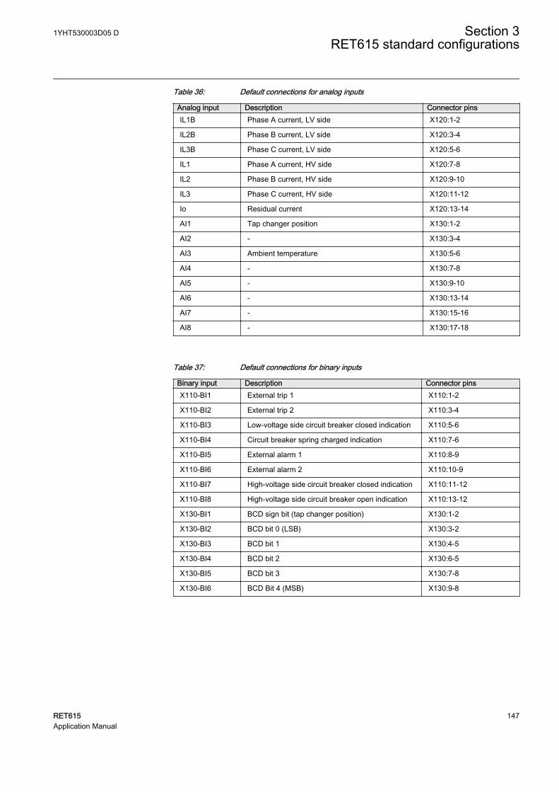
Table 36: Default connections for analog inputs
Analog input Description Connector pinsIL1B Phase A current, LV side X120:1-2
IL2B Phase B current, LV side X120:3-4
IL3B Phase C current, LV side X120:5-6
IL1 Phase A current, HV side X120:7-8
IL2 Phase B current, HV side X120:9-10
IL3 Phase C current, HV side X120:11-12
Io Residual current X120:13-14
AI1 Tap changer position X130:1-2
AI2 - X130:3-4
AI3 Ambient temperature X130:5-6
AI4 - X130:7-8
AI5 - X130:9-10
AI6 - X130:13-14
AI7 - X130:15-16
AI8 - X130:17-18
Table 37: Default connections for binary inputs
Binary input Description Connector pinsX110-BI1 External trip 1 X110:1-2
X110-BI2 External trip 2 X110:3-4
X110-BI3 Low-voltage side circuit breaker closed indication X110:5-6
X110-BI4 Circuit breaker spring charged indication X110:7-6
X110-BI5 External alarm 1 X110:8-9
X110-BI6 External alarm 2 X110:10-9
X110-BI7 High-voltage side circuit breaker closed indication X110:11-12
X110-BI8 High-voltage side circuit breaker open indication X110:13-12
X130-BI1 BCD sign bit (tap changer position) X130:1-2
X130-BI2 BCD bit 0 (LSB) X130:3-2
X130-BI3 BCD bit 1 X130:4-5
X130-BI4 BCD bit 2 X130:6-5
X130-BI5 BCD bit 3 X130:7-8
X130-BI6 BCD Bit 4 (MSB) X130:9-8
1YHT530003D05 D Section 3RET615 standard configurations
RET615 147Application Manual
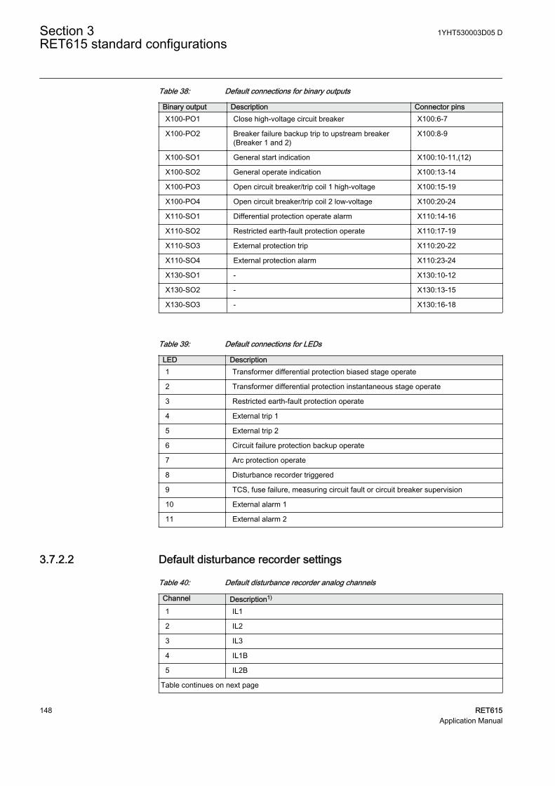
Table 38: Default connections for binary outputs
Binary output Description Connector pinsX100-PO1 Close high-voltage circuit breaker X100:6-7
X100-PO2 Breaker failure backup trip to upstream breaker(Breaker 1 and 2)
X100:8-9
X100-SO1 General start indication X100:10-11,(12)
X100-SO2 General operate indication X100:13-14
X100-PO3 Open circuit breaker/trip coil 1 high-voltage X100:15-19
X100-PO4 Open circuit breaker/trip coil 2 low-voltage X100:20-24
X110-SO1 Differential protection operate alarm X110:14-16
X110-SO2 Restricted earth-fault protection operate X110:17-19
X110-SO3 External protection trip X110:20-22
X110-SO4 External protection alarm X110:23-24
X130-SO1 - X130:10-12
X130-SO2 - X130:13-15
X130-SO3 - X130:16-18
Table 39: Default connections for LEDs
LED Description1 Transformer differential protection biased stage operate
2 Transformer differential protection instantaneous stage operate
3 Restricted earth-fault protection operate
4 External trip 1
5 External trip 2
6 Circuit failure protection backup operate
7 Arc protection operate
8 Disturbance recorder triggered
9 TCS, fuse failure, measuring circuit fault or circuit breaker supervision
10 External alarm 1
11 External alarm 2
3.7.2.2 Default disturbance recorder settings
Table 40: Default disturbance recorder analog channels
Channel Description1)
1 IL1
2 IL2
3 IL3
4 IL1B
5 IL2B
Table continues on next page
Section 3 1YHT530003D05 DRET615 standard configurations
148 RET615Application Manual
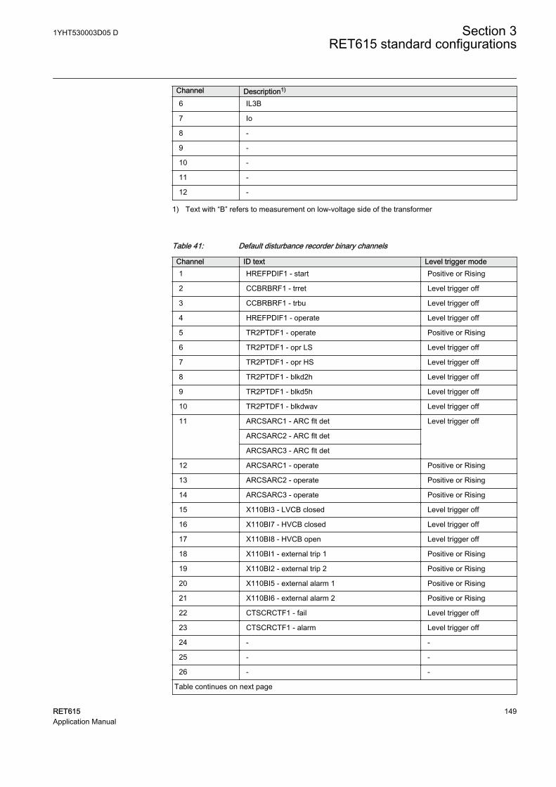
Channel Description1)
6 IL3B
7 Io
8 -
9 -
10 -
11 -
12 -
1) Text with “B” refers to measurement on low-voltage side of the transformer
Table 41: Default disturbance recorder binary channels
Channel ID text Level trigger mode1 HREFPDIF1 - start Positive or Rising
2 CCBRBRF1 - trret Level trigger off
3 CCBRBRF1 - trbu Level trigger off
4 HREFPDIF1 - operate Level trigger off
5 TR2PTDF1 - operate Positive or Rising
6 TR2PTDF1 - opr LS Level trigger off
7 TR2PTDF1 - opr HS Level trigger off
8 TR2PTDF1 - blkd2h Level trigger off
9 TR2PTDF1 - blkd5h Level trigger off
10 TR2PTDF1 - blkdwav Level trigger off
11 ARCSARC1 - ARC flt det Level trigger off
ARCSARC2 - ARC flt det
ARCSARC3 - ARC flt det
12 ARCSARC1 - operate Positive or Rising
13 ARCSARC2 - operate Positive or Rising
14 ARCSARC3 - operate Positive or Rising
15 X110BI3 - LVCB closed Level trigger off
16 X110BI7 - HVCB closed Level trigger off
17 X110BI8 - HVCB open Level trigger off
18 X110BI1 - external trip 1 Positive or Rising
19 X110BI2 - external trip 2 Positive or Rising
20 X110BI5 - external alarm 1 Positive or Rising
21 X110BI6 - external alarm 2 Positive or Rising
22 CTSCRCTF1 - fail Level trigger off
23 CTSCRCTF1 - alarm Level trigger off
24 - -
25 - -
26 - -
Table continues on next page
1YHT530003D05 D Section 3RET615 standard configurations
RET615 149Application Manual
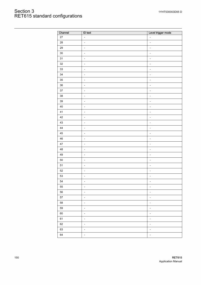
Channel ID text Level trigger mode27 - -
28 - -
29 - -
30 - -
31 - -
32 - -
33 - -
34 - -
35 - -
36 - -
37 - -
38 - -
39 - -
40 - -
41 - -
42 - -
43 - -
44 - -
45 - -
46 - -
47 - -
48 - -
49 - -
50 - -
51 - -
52 - -
53 - -
54 - -
55 - -
56 - -
57 - -
58 - -
59 - -
60 - -
61 - -
62 - -
63 - -
64 - -
Section 3 1YHT530003D05 DRET615 standard configurations
150 RET615Application Manual
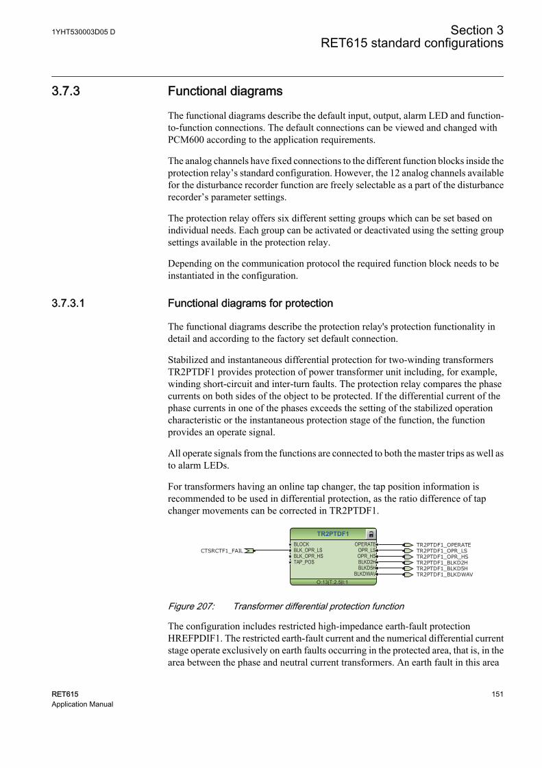
3.7.3 Functional diagrams
The functional diagrams describe the default input, output, alarm LED and function-to-function connections. The default connections can be viewed and changed withPCM600 according to the application requirements.
The analog channels have fixed connections to the different function blocks inside theprotection relay’s standard configuration. However, the 12 analog channels availablefor the disturbance recorder function are freely selectable as a part of the disturbancerecorder’s parameter settings.
The protection relay offers six different setting groups which can be set based onindividual needs. Each group can be activated or deactivated using the setting groupsettings available in the protection relay.
Depending on the communication protocol the required function block needs to beinstantiated in the configuration.
3.7.3.1 Functional diagrams for protection
The functional diagrams describe the protection relay's protection functionality indetail and according to the factory set default connection.
Stabilized and instantaneous differential protection for two-winding transformersTR2PTDF1 provides protection of power transformer unit including, for example,winding short-circuit and inter-turn faults. The protection relay compares the phasecurrents on both sides of the object to be protected. If the differential current of thephase currents in one of the phases exceeds the setting of the stabilized operationcharacteristic or the instantaneous protection stage of the function, the functionprovides an operate signal.
All operate signals from the functions are connected to both the master trips as well asto alarm LEDs.
For transformers having an online tap changer, the tap position information isrecommended to be used in differential protection, as the ratio difference of tapchanger movements can be corrected in TR2PTDF1.
TR2PTDF1
O:13|T:2.5|I:1
BLOCKBLK_OPR_LSBLK_OPR_HSTAP_POS
OPERATEOPR_LSOPR_HSBLKD2HBLKD5H
BLKDWAV
TR2PTDF1_OPERATECTSRCTF1_FAIL TR2PTDF1_OPR_LS
TR2PTDF1_OPR_HSTR2PTDF1_BLKD2HTR2PTDF1_BLKD5HTR2PTDF1_BLKDWAV
GUID-2D71E645-5684-4A3A-8192-1A77E5B0A179 V1 EN
Figure 207: Transformer differential protection function
The configuration includes restricted high-impedance earth-fault protectionHREFPDIF1. The restricted earth-fault current and the numerical differential currentstage operate exclusively on earth faults occurring in the protected area, that is, in thearea between the phase and neutral current transformers. An earth fault in this area
1YHT530003D05 D Section 3RET615 standard configurations
RET615 151Application Manual
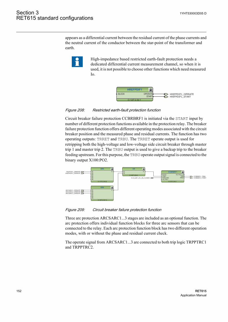
appears as a differential current between the residual current of the phase currents andthe neutral current of the conductor between the star-point of the transformer andearth.
High-impedance based restricted earth-fault protection needs adedicated differential current measurement channel, so when it isused, it is not possible to choose other functions which need measuredIo.
HREFPDIF1
O:12|T:2.5|I:1
BLOCK OPERATESTART
HREFPDIF1_OPERATEHREFPDIF1_START
GUID-576A3076-0167-4E0F-9947-8B8DBA375B8B V1 EN
Figure 208: Restricted earth-fault protection function
Circuit breaker failure protection CCBRBRF1 is initiated via the START input bynumber of different protection functions available in the protection relay. The breakerfailure protection function offers different operating modes associated with the circuitbreaker position and the measured phase and residual currents. The function has twooperating outputs: TRRET and TRBU. The TRRET operate output is used forretripping both the high-voltage and low-voltage side circuit breaker through mastertrip 1 and master trip 2. The TRBU output is used to give a backup trip to the breakerfeeding upstream. For this purpose, the TRBU operate output signal is connected to thebinary output X100:PO2.
CCBRBRF1
O:21|T:2.5|I:1
BLOCKSTARTPOSCLOSECB_FAULT
CB_FAULT_ALTRBU
TRRET
OR6
O:17|T:2.5|I:22
B1B2B3B4B5B6
O
OR6
O:18|T:2.5|I:13
B1B2B3B4B5B6
O
OR
O:19|T:2.5|I:6
B1B2
O
CCBRBRF1_TRBUX110_BI7_HV_CB_CLOSED
HREFPDIF1_OPERATETR2PTDF1_OPERATE
CCBRBRF1_TRRET
ARCSARC1_OPERATEARCSARC2_OPERATEARCSARC3_OPERATE
GUID-CBF49D4F-1A2C-4C52-99B6-40574F3B635E V1 EN
Figure 209: Circuit breaker failure protection function
Three arc protection ARCSARC1...3 stages are included as an optional function. Thearc protection offers individual function blocks for three arc sensors that can beconnected to the relay. Each arc protection function block has two different operationmodes, with or without the phase and residual current check.
The operate signal from ARCSARC1...3 are connected to both trip logic TRPPTRC1and TRPPTRC2.
Section 3 1YHT530003D05 DRET615 standard configurations
152 RET615Application Manual
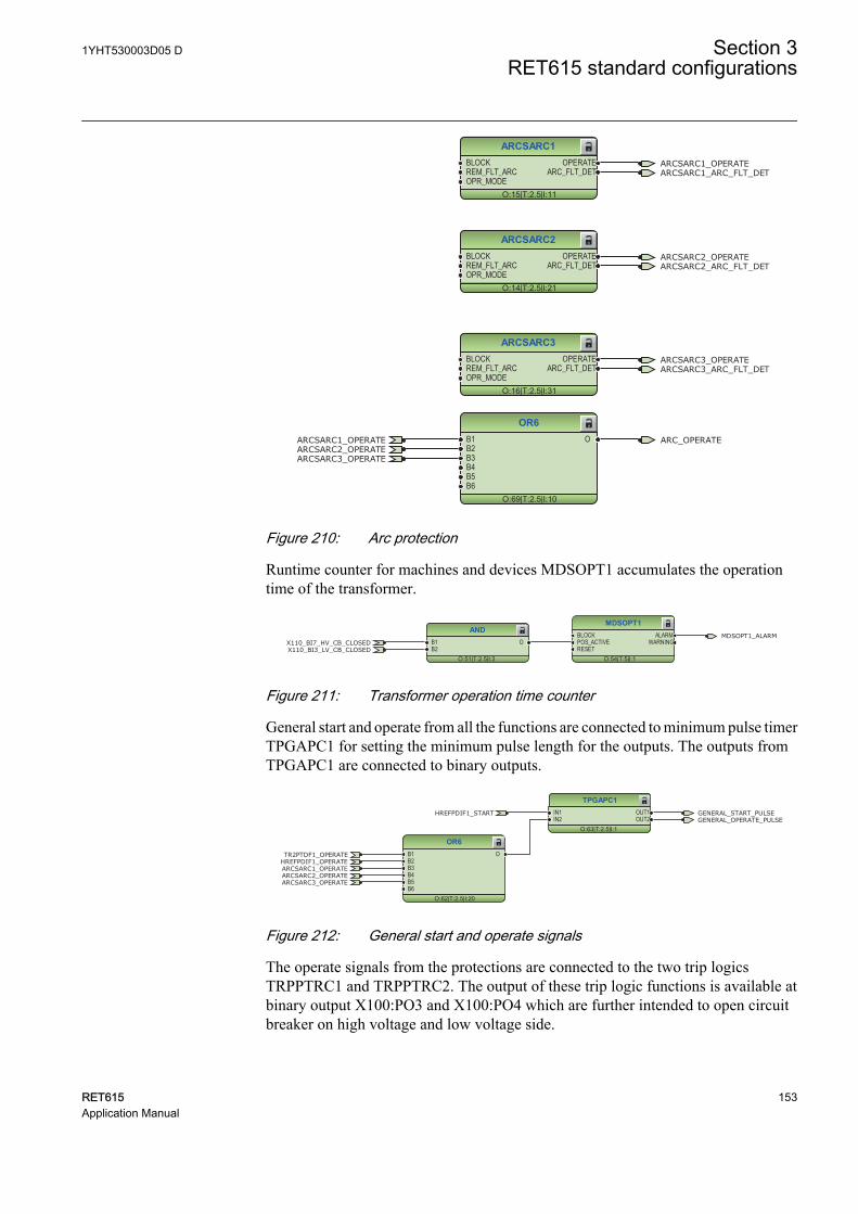
ARCSARC1
O:15|T:2.5|I:11
BLOCKREM_FLT_ARCOPR_MODE
OPERATEARC_FLT_DET
ARCSARC2
O:14|T:2.5|I:21
BLOCKREM_FLT_ARCOPR_MODE
OPERATEARC_FLT_DET
ARCSARC3
O:16|T:2.5|I:31
BLOCKREM_FLT_ARCOPR_MODE
OPERATEARC_FLT_DET
ARCSARC1_OPERATE
ARCSARC2_OPERATE
ARCSARC3_OPERATE
ARCSARC1_ARC_FLT_DET
ARCSARC2_ARC_FLT_DET
ARCSARC3_ARC_FLT_DET
GUID-2AD2E267-6465-455F-BA4C-76D8EB6C20E4 V1 EN
OR6
O:69|T:2.5|I:10
B1B2B3B4B5B6
OARCSARC1_OPERATEARCSARC2_OPERATEARCSARC3_OPERATE
ARC_OPERATE
GUID-B227A4E4-C0A1-4EB2-82A5-2F3D4C529EFC V1 EN
Figure 210: Arc protection
Runtime counter for machines and devices MDSOPT1 accumulates the operationtime of the transformer.
MDSOPT1
O:54|T:5|I:1
BLOCKPOS_ACTIVERESET
ALARMWARNING
AND
O:51|T:2.5|I:3
B1B2
OX110_BI7_HV_CB_CLOSEDX110_BI3_LV_CB_CLOSED
MDSOPT1_ALARM
GUID-53A113DE-E5A2-47F8-8682-2C03C2A2BC1C V1 EN
Figure 211: Transformer operation time counter
General start and operate from all the functions are connected to minimum pulse timerTPGAPC1 for setting the minimum pulse length for the outputs. The outputs fromTPGAPC1 are connected to binary outputs.
OR6
O:62|T:2.5|I:20
B1B2B3B4B5B6
O
TPGAPC1
O:63|T:2.5|I:1
IN1IN2
OUT1OUT2
GENERAL_START_PULSEGENERAL_OPERATE_PULSE
HREFPDIF1_OPERATETR2PTDF1_OPERATE
ARCSARC1_OPERATEARCSARC2_OPERATEARCSARC3_OPERATE
HREFPDIF1_START
GUID-742B5BB4-9604-47B5-98C5-CC499DA439CF V1 EN
Figure 212: General start and operate signals
The operate signals from the protections are connected to the two trip logicsTRPPTRC1 and TRPPTRC2. The output of these trip logic functions is available atbinary output X100:PO3 and X100:PO4 which are further intended to open circuitbreaker on high voltage and low voltage side.
1YHT530003D05 D Section 3RET615 standard configurations
RET615 153Application Manual
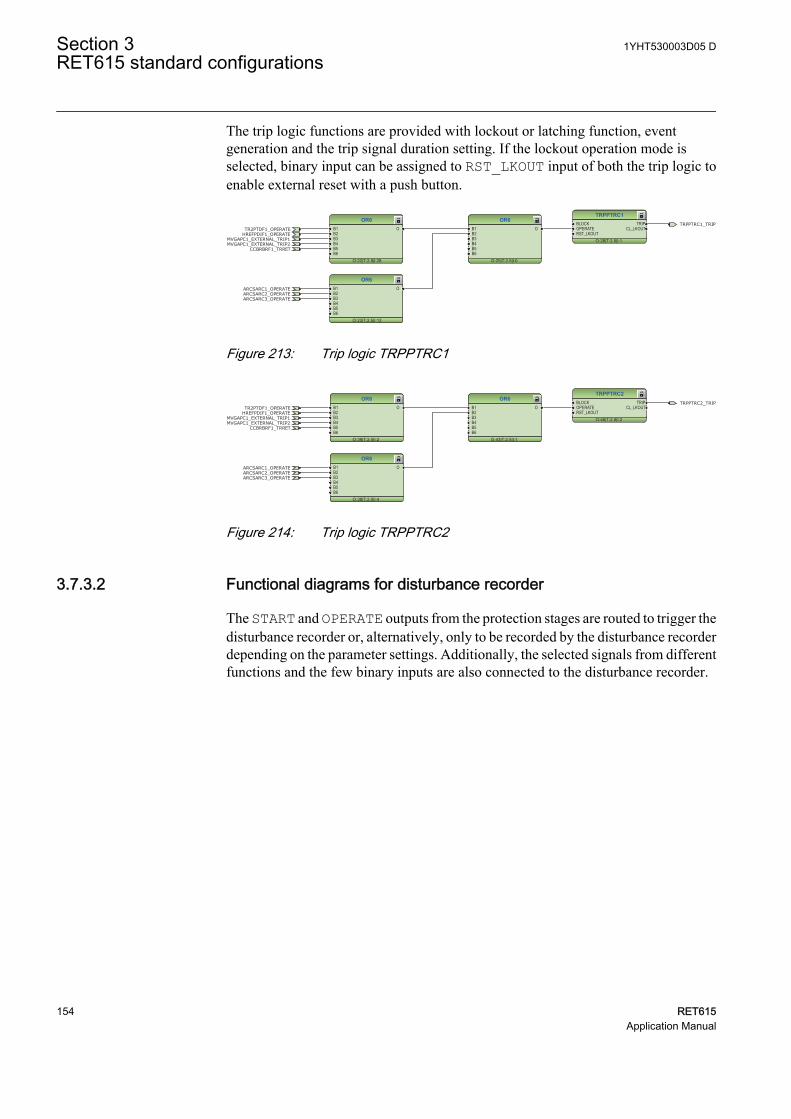
The trip logic functions are provided with lockout or latching function, eventgeneration and the trip signal duration setting. If the lockout operation mode isselected, binary input can be assigned to RST_LKOUT input of both the trip logic toenable external reset with a push button.
TRPPTRC1
O:28|T:2.5|I:1
BLOCKOPERATERST_LKOUT
TRIPCL_LKOUT
OR6
O:22|T:2.5|I:28
B1B2B3B4B5B6
O
OR6
O:23|T:2.5|I:12
B1B2B3B4B5B6
O
OR6
O:25|T:2.5|I:0
B1B2B3B4B5B6
OTRPPTRC1_TRIP
HREFPDIF1_OPERATETR2PTDF1_OPERATE
MVGAPC1_EXTERNAL_TRIP1MVGAPC1_EXTERNAL_TRIP2
CCBRBRF1_TRRET
ARCSARC1_OPERATEARCSARC2_OPERATEARCSARC3_OPERATE
GUID-3B03217E-3BD1-477A-B76F-A7F571036A49 V1 EN
Figure 213: Trip logic TRPPTRC1
OR6
O:43|T:2.5|I:1
B1B2B3B4B5B6
O
TRPPTRC2
O:46|T:2.5|I:2
BLOCKOPERATERST_LKOUT
TRIPCL_LKOUT
OR6
O:39|T:2.5|I:2
B1B2B3B4B5B6
O
OR6
O:38|T:2.5|I:4
B1B2B3B4B5B6
O
HREFPDIF1_OPERATETR2PTDF1_OPERATE
MVGAPC1_EXTERNAL_TRIP1MVGAPC1_EXTERNAL_TRIP2
CCBRBRF1_TRRET
ARCSARC1_OPERATEARCSARC2_OPERATEARCSARC3_OPERATE
TRPPTRC2_TRIP
GUID-7DCD44ED-BC5C-4BDB-88F6-C2341B714C18 V1 EN
Figure 214: Trip logic TRPPTRC2
3.7.3.2 Functional diagrams for disturbance recorder
The START and OPERATE outputs from the protection stages are routed to trigger thedisturbance recorder or, alternatively, only to be recorded by the disturbance recorderdepending on the parameter settings. Additionally, the selected signals from differentfunctions and the few binary inputs are also connected to the disturbance recorder.
Section 3 1YHT530003D05 DRET615 standard configurations
154 RET615Application Manual
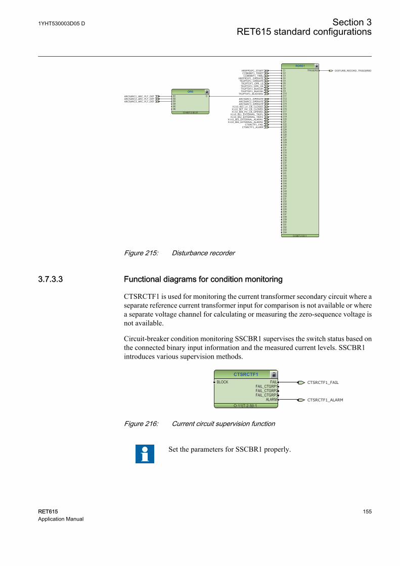
RDRE1
O:59|T:2.5|I:1
C1C2C3C4C5C6C7C8C9C10C11C12C13C14C15C16C17C18C19C20C21C22C23C24C25C26C27C28C29C30C31C32C33C34C35C36C37C38C39C40C41C42C43C44C45C46C47C48C49C50C51C52C53C54C55C56C57C58C59C60C61C62C63C64
TRIGGERED
OR6
O:58|T:2.5|I:21
B1B2B3B4B5B6
O
CCBRBRF1_TRBU
X110_BI8_HV_CB_OPENEDX110_BI7_HV_CB_CLOSED
X110_BI6_EXTERNAL_ALARM2X110_BI5_EXTERNAL_ALARM1
HREFPDIF1_OPERATETR2PTDF1_OPERATE
CCBRBRF1_TRRET
ARCSARC1_OPERATEARCSARC2_OPERATEARCSARC3_OPERATE
HREFPDIF1_START
CTSRCTF1_FAIL
X110_BI3_LV_CB_CLOSED
X110_BI1_EXTERNAL_TRIP1X110_BI2_EXTERNAL_TRIP2
ARCSARC1_ARC_FLT_DETARCSARC2_ARC_FLT_DETARCSARC3_ARC_FLT_DET
TR2PTDF1_OPR_LSTR2PTDF1_OPR_HSTR2PTDF1_BLKD2HTR2PTDF1_BLKD5H
TR2PTDF1_BLKDWAV
CTSRCTF1_ALARM
DISTURB_RECORD_TRIGGERED
GUID-AAC30B41-BB6E-4428-B786-09939A1F21E4 V1 EN
Figure 215: Disturbance recorder
3.7.3.3 Functional diagrams for condition monitoring
CTSRCTF1 is used for monitoring the current transformer secondary circuit where aseparate reference current transformer input for comparison is not available or wherea separate voltage channel for calculating or measuring the zero-sequence voltage isnot available.
Circuit-breaker condition monitoring SSCBR1 supervises the switch status based onthe connected binary input information and the measured current levels. SSCBR1introduces various supervision methods.
CTSRCTF1
O:11|T:2.5|I:1
BLOCK FAILFAIL_CTGRP1FAIL_CTGRP2FAIL_CTGRP3
ALARM
CTSRCTF1_FAIL
CTSRCTF1_ALARM
GUID-C58A2E59-A2F8-49AA-92C8-731B7D9E54A4 V1 EN
Figure 216: Current circuit supervision function
Set the parameters for SSCBR1 properly.
1YHT530003D05 D Section 3RET615 standard configurations
RET615 155Application Manual
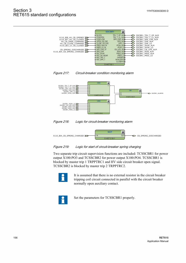
SSCBR1
O:44|T:5|I:1
BLOCKPOSOPENPOSCLOSEOPEN_CB_EXECLOSE_CB_EXEPRES_ALM_INPRES_LO_INSPR_CHR_STSPR_CHRRST_IPOWRST_CB_WEARRST_TRV_TRST_SPR_T
TRV_T_OP_ALMTRV_T_CL_ALMSPR_CHR_ALM
OPR_ALMOPR_LO
IPOW_ALMIPOW_LO
CB_LIFE_ALMMON_ALM
PRES_ALMPRES_LO
OPENPOSINVALIDPOSCLOSEPOS
HV_CB_CLOSE_COMMANDHV_CB_OPEN_COMMAND
X110_BI8_HV_CB_OPENEDX110_BI7_HV_CB_CLOSED
X110_BI4_CB_SPRING_CHARGED
X110_BI3_LV_CB_CLOSED
CB_SPRING_DISCHARGED
SSCBR1_TRV_T_OP_ALMSSCBR1_TRV_T_CL_ALMSSCBR1_SPR_CHR_ALMSSCBR1_OPR_ALMSSCBR1_OPR_LOSSCBR1_IPOW_ALMSSCBR1_IPOW_LO
SSCBR1_MON_ALMSSCBR1_PRES_ALMSSCBR1_PRES_LO
SSCBR1_CB_LIFE_ALM
GUID-1C2DDCD2-0D69-4218-B34D-354C4A36F62E V2 EN
Figure 217: Circuit-breaker condition monitoring alarm
OR6
O:48|T:2.5|I:26
B1B2B3B4B5B6
O
OR6
O:47|T:2.5|I:5
B1B2B3B4B5B6
O
OR
O:52|T:2.5|I:21
B1B2
O
SSCBR1_TRV_T_OP_ALMSSCBR1_TRV_T_CL_ALMSSCBR1_SPR_CHR_ALM
SSCBR1_OPR_ALMSSCBR1_OPR_LO
SSCBR1_IPOW_ALM
SSCBR1_IPOW_LO
SSCBR1_MON_ALMSSCBR1_PRES_ALM
SSCBR1_PRES_LO
SSCBR1_ALARMS
SSCBR1_CB_LIFE_ALM
GUID-0828AF3C-51EF-461A-871A-0BBFD14029A4 V1 EN
Figure 218: Logic for circuit-breaker monitoring alarm
NOT
O:40|T:2.5|I:1IN OUTX110_BI4_CB_SPRING_CHARGED CB_SPRING_DISCHARGED
GUID-D52DAD24-4433-4E41-B516-E520815DE3C0 V1 EN
Figure 219: Logic for start of circuit-breaker spring charging
Two separate trip circuit supervision functions are included: TCSSCBR1 for poweroutput X100:PO3 and TCSSCBR2 for power output X100:PO4. TCSSCBR1 isblocked by master trip 1 TRPPTRC1 and HV side circuit breaker open signal.TCSSCBR2 is blocked by master trip 2 TRPPTRC2.
It is assumed that there is no external resistor in the circuit breakertripping coil circuit connected in parallel with the circuit breakernormally open auxiliary contact.
Set the parameters for TCSSCBR1 properly.
Section 3 1YHT530003D05 DRET615 standard configurations
156 RET615Application Manual
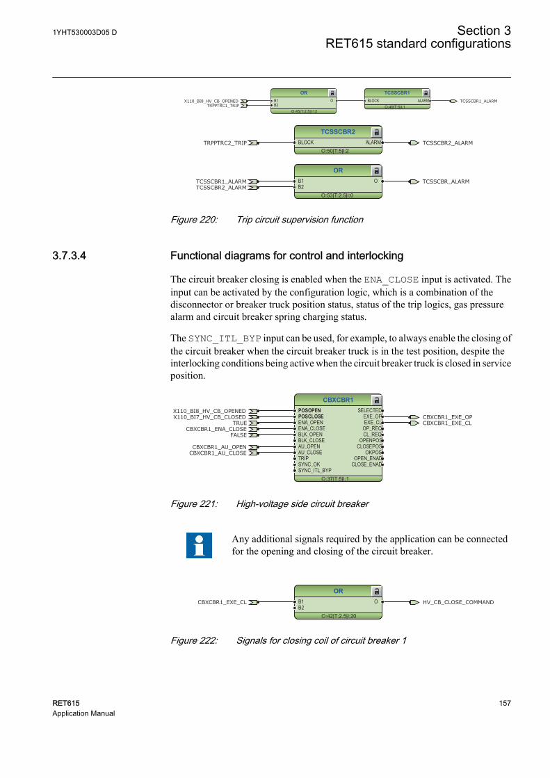
TCSSCBR1
O:49|T:5|I:1BLOCK ALARM
OR
O:45|T:2.5|I:12
B1B2
OTRPPTRC1_TRIP
X110_BI8_HV_CB_OPENED TCSSCBR1_ALARM
GUID-EF1E38B4-05FD-4903-9143-8241123A8644 V1 EN
TCSSCBR2
O:50|T:5|I:2BLOCK ALARMTRPPTRC2_TRIP TCSSCBR2_ALARM
GUID-E52900FC-D5C3-4466-86EB-156C81540623 V1 EN
OR
O:53|T:2.5|I:0
B1B2
OTCSSCBR1_ALARMTCSSCBR2_ALARM
TCSSCBR_ALARM
GUID-17333F81-388C-4313-854F-13450F1DA542 V1 EN
Figure 220: Trip circuit supervision function
3.7.3.4 Functional diagrams for control and interlocking
The circuit breaker closing is enabled when the ENA_CLOSE input is activated. Theinput can be activated by the configuration logic, which is a combination of thedisconnector or breaker truck position status, status of the trip logics, gas pressurealarm and circuit breaker spring charging status.
The SYNC_ITL_BYP input can be used, for example, to always enable the closing ofthe circuit breaker when the circuit breaker truck is in the test position, despite theinterlocking conditions being active when the circuit breaker truck is closed in serviceposition.
CBXCBR1
O:37|T:5|I:1
POSOPENPOSCLOSEENA_OPENENA_CLOSEBLK_OPENBLK_CLOSEAU_OPENAU_CLOSETRIPSYNC_OKSYNC_ITL_BYP
SELECTEDEXE_OPEXE_CL
OP_REQCL_REQ
OPENPOSCLOSEPOS
OKPOSOPEN_ENAD
CLOSE_ENAD
TRUECBXCBR1_ENA_CLOSE
CBXCBR1_EXE_OPCBXCBR1_EXE_CL
X110_BI8_HV_CB_OPENEDX110_BI7_HV_CB_CLOSED
FALSE
CBXCBR1_AU_OPENCBXCBR1_AU_CLOSE
GUID-7E3FB390-C056-4045-8F7D-B7D40FF8DB08 V1 EN
Figure 221: High-voltage side circuit breaker
Any additional signals required by the application can be connectedfor the opening and closing of the circuit breaker.
OR
O:42|T:2.5|I:20
B1B2
O HV_CB_CLOSE_COMMANDCBXCBR1_EXE_CL
GUID-E1C914EB-EB55-42FE-8406-429416C100F0 V1 EN
Figure 222: Signals for closing coil of circuit breaker 1
1YHT530003D05 D Section 3RET615 standard configurations
RET615 157Application Manual
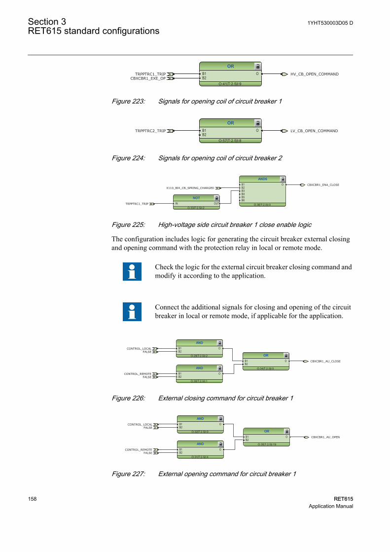
OR
O:41|T:2.5|I:9
B1B2
O HV_CB_OPEN_COMMANDTRPPTRC1_TRIPCBXCBR1_EXE_OP
GUID-5A03204C-D023-498A-9886-ED3F92114DB9 V1 EN
Figure 223: Signals for opening coil of circuit breaker 1
OR
O:57|T:2.5|I:8
B1B2
O LV_CB_OPEN_COMMANDTRPPTRC2_TRIP
GUID-8CC3656F-E62A-4566-8C21-6EF007BC43AE V1 EN
Figure 224: Signals for opening coil of circuit breaker 2
NOT
O:33|T:2.5|I:2IN OUT
AND6
O:36|T:2.5|I:0
B1B2B3B4B5B6
O
TRPPTRC1_TRIP
CBXCBR1_ENA_CLOSEX110_BI4_CB_SPRING_CHARGED
GUID-6EDDB750-D3E9-49ED-82EB-81E43094098E V1 EN
Figure 225: High-voltage side circuit breaker 1 close enable logic
The configuration includes logic for generating the circuit breaker external closingand opening command with the protection relay in local or remote mode.
Check the logic for the external circuit breaker closing command andmodify it according to the application.
Connect the additional signals for closing and opening of the circuitbreaker in local or remote mode, if applicable for the application.
AND
O:29|T:2.5|I:2
B1B2
O
AND
O:30|T:2.5|I:1
B1B2
O
OR
O:34|T:2.5|I:5
B1B2
O
CONTROL_LOCAL
CONTROL_REMOTE
FALSE
FALSE
CBXCBR1_AU_CLOSE
GUID-301EB910-611B-4BD9-8D38-3B858A2C4C65 V1 EN
Figure 226: External closing command for circuit breaker 1
AND
O:31|T:2.5|I:4
B1B2
O
OR
O:35|T:2.5|I:19
B1B2
O
AND
O:32|T:2.5|I:0
B1B2
OCONTROL_LOCAL
CONTROL_REMOTE
FALSE
FALSE
CBXCBR1_AU_OPEN
GUID-4BCDB69B-3652-45E1-A256-615B7D85A77D V1 EN
Figure 227: External opening command for circuit breaker 1
Section 3 1YHT530003D05 DRET615 standard configurations
158 RET615Application Manual
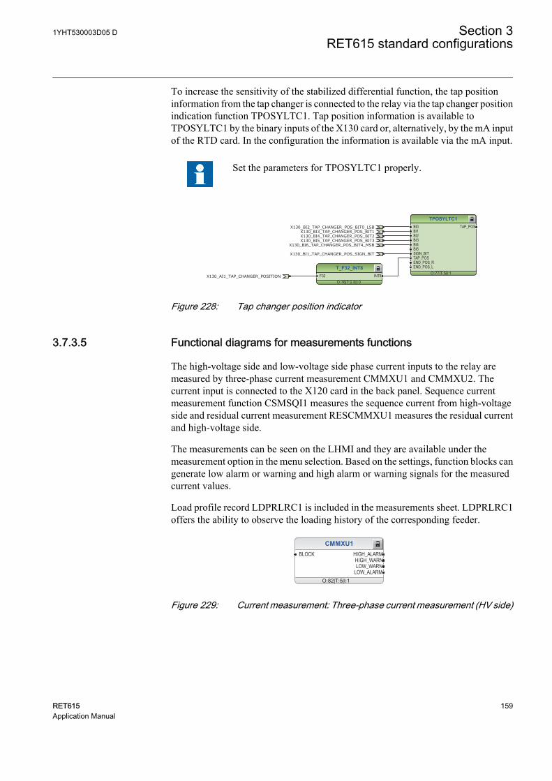
To increase the sensitivity of the stabilized differential function, the tap positioninformation from the tap changer is connected to the relay via the tap changer positionindication function TPOSYLTC1. Tap position information is available toTPOSYLTC1 by the binary inputs of the X130 card or, alternatively, by the mA inputof the RTD card. In the configuration the information is available via the mA input.
Set the parameters for TPOSYLTC1 properly.
TPOSYLTC1
O:77|T:5|I:1
BI0BI1BI2BI3BI4BI5SIGN_BITTAP_POSEND_POS_REND_POS_L
TAP_POS
T_F32_INT8
O:76|T:2.5|I:0F32 INT8
X130_BI2_TAP_CHANGER_POS_BIT0_LSBX130_BI3_TAP_CHANGER_POS_BIT1X130_BI4_TAP_CHANGER_POS_BIT2X130_BI5_TAP_CHANGER_POS_BIT3
X130_BI6_TAP_CHANGER_POS_BIT4_MSB
X130_BI1_TAP_CHANGER_POS_SIGN_BIT
X130_AI1_TAP_CHANGER_POSITION
GUID-A2B9E9AC-9CC7-4951-9A51-0C25C9952B36 V1 EN
Figure 228: Tap changer position indicator
3.7.3.5 Functional diagrams for measurements functions
The high-voltage side and low-voltage side phase current inputs to the relay aremeasured by three-phase current measurement CMMXU1 and CMMXU2. Thecurrent input is connected to the X120 card in the back panel. Sequence currentmeasurement function CSMSQI1 measures the sequence current from high-voltageside and residual current measurement RESCMMXU1 measures the residual currentand high-voltage side.
The measurements can be seen on the LHMI and they are available under themeasurement option in the menu selection. Based on the settings, function blocks cangenerate low alarm or warning and high alarm or warning signals for the measuredcurrent values.
Load profile record LDPRLRC1 is included in the measurements sheet. LDPRLRC1offers the ability to observe the loading history of the corresponding feeder.
CMMXU1
O:82|T:5|I:1
BLOCK HIGH_ALARMHIGH_WARNLOW_WARN
LOW_ALARM
GUID-BF26A15B-D857-42DC-AD62-042BAC3A203E V1 EN
Figure 229: Current measurement: Three-phase current measurement (HV side)
1YHT530003D05 D Section 3RET615 standard configurations
RET615 159Application Manual

CMMXU2
O:86|T:5|I:2
BLOCK HIGH_ALARMHIGH_WARNLOW_WARN
LOW_ALARM
GUID-28C919F7-CB17-47B9-9419-6B41B42BCB3C V1 EN
Figure 230: Current measurement: Three-phase current measurement (LV side)
CSMSQI1
O:80|T:5|I:1
GUID-4A3E22D1-C73B-44B4-AE35-0B0178E9B53F V1 EN
Figure 231: Current measurement: Sequence current measurement (HV side)
RESCMMXU1
O:84|T:5|I:1
BLOCK HIGH_ALARMHIGH_WARN
GUID-625B086B-5EB1-4050-88AE-6CA48A4FDAFB V1 EN
Figure 232: Current measurement: Residual current measurement (HV side)
FLTRFRC1
O:8|T:2.5|I:1
BLOCKCB_CLRD
GUID-84364C83-CBF5-4E8C-8765-1889FE8E4B74 V1 EN
Figure 233: Other measurement: Data monitoring
LDPRLRC1
O:85|T:5|I:1
RSTMEM MEM_WARNMEM_ALARM
GUID-53CEBDD1-137D-46A5-9006-B19E6A7B0F8B V1 EN
Figure 234: Other measurement: Load profile record
Section 3 1YHT530003D05 DRET615 standard configurations
160 RET615Application Manual
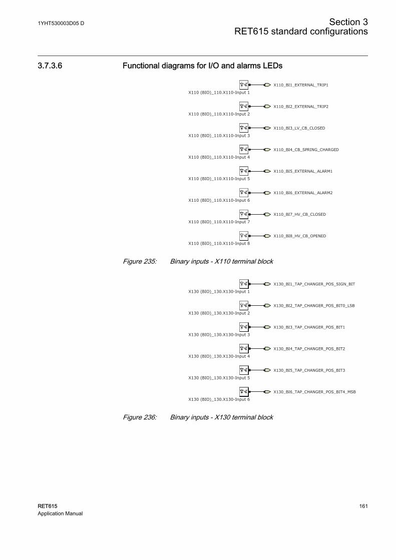
3.7.3.6 Functional diagrams for I/O and alarms LEDs
X110_BI8_HV_CB_OPENED
X110_BI7_HV_CB_CLOSED
X110_BI4_CB_SPRING_CHARGED
X110_BI6_EXTERNAL_ALARM2
X110_BI5_EXTERNAL_ALARM1
X110_BI3_LV_CB_CLOSED
X110_BI1_EXTERNAL_TRIP1
X110_BI2_EXTERNAL_TRIP2
X110 (BIO)_110.X110-Input 1
X110 (BIO)_110.X110-Input 2
X110 (BIO)_110.X110-Input 3
X110 (BIO)_110.X110-Input 4
X110 (BIO)_110.X110-Input 5
X110 (BIO)_110.X110-Input 6
X110 (BIO)_110.X110-Input 7
X110 (BIO)_110.X110-Input 8GUID-63C65B52-E01C-42DA-816C-8BEDDF848A7C V1 EN
Figure 235: Binary inputs - X110 terminal block
X130_BI2_TAP_CHANGER_POS_BIT0_LSB
X130_BI3_TAP_CHANGER_POS_BIT1
X130_BI4_TAP_CHANGER_POS_BIT2
X130_BI5_TAP_CHANGER_POS_BIT3
X130_BI6_TAP_CHANGER_POS_BIT4_MSB
X130_BI1_TAP_CHANGER_POS_SIGN_BIT
X130 (BIO)_130.X130-Input 1
X130 (BIO)_130.X130-Input 2
X130 (BIO)_130.X130-Input 3
X130 (BIO)_130.X130-Input 4
X130 (BIO)_130.X130-Input 5
X130 (BIO)_130.X130-Input 6GUID-9633F8D0-EBDE-4287-B8C2-2A2EDC875AD3 V1 EN
Figure 236: Binary inputs - X130 terminal block
1YHT530003D05 D Section 3RET615 standard configurations
RET615 161Application Manual
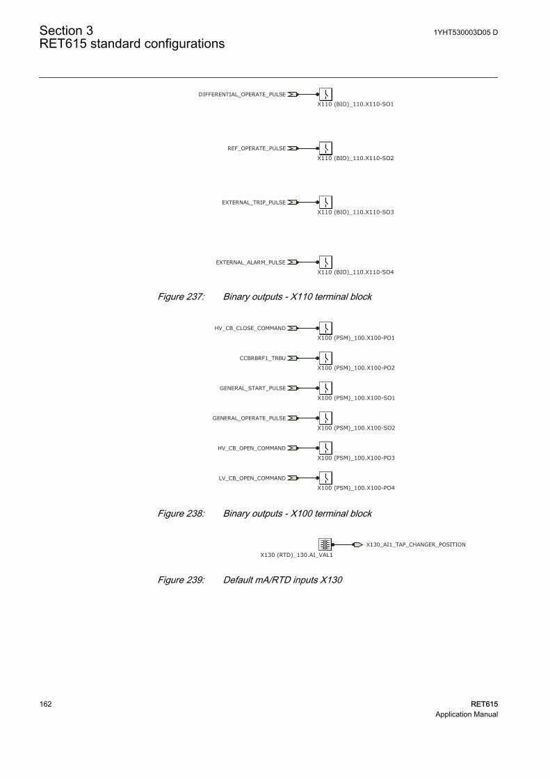
DIFFERENTIAL_OPERATE_PULSE
REF_OPERATE_PULSE
EXTERNAL_TRIP_PULSE
EXTERNAL_ALARM_PULSE
X110 (BIO)_110.X110-SO1
X110 (BIO)_110.X110-SO2
X110 (BIO)_110.X110-SO4
X110 (BIO)_110.X110-SO3
GUID-A26BEFDB-712C-4324-BCB7-22DE162742F7 V1 EN
Figure 237: Binary outputs - X110 terminal block
HV_CB_CLOSE_COMMAND
HV_CB_OPEN_COMMAND
GENERAL_START_PULSE
GENERAL_OPERATE_PULSE
LV_CB_OPEN_COMMAND
CCBRBRF1_TRBU
X100 (PSM)_100.X100-PO1
X100 (PSM)_100.X100-PO2
X100 (PSM)_100.X100-SO1
X100 (PSM)_100.X100-SO2
X100 (PSM)_100.X100-PO3
X100 (PSM)_100.X100-PO4
GUID-88080E2A-54B2-4CFB-A863-3896401862E0 V1 EN
Figure 238: Binary outputs - X100 terminal block
X130_AI1_TAP_CHANGER_POSITION
X130 (RTD)_130.AI_VAL1GUID-DC2A98AE-EE37-4DA0-B757-EABF5A410175 V1 EN
Figure 239: Default mA/RTD inputs X130
Section 3 1YHT530003D05 DRET615 standard configurations
162 RET615Application Manual
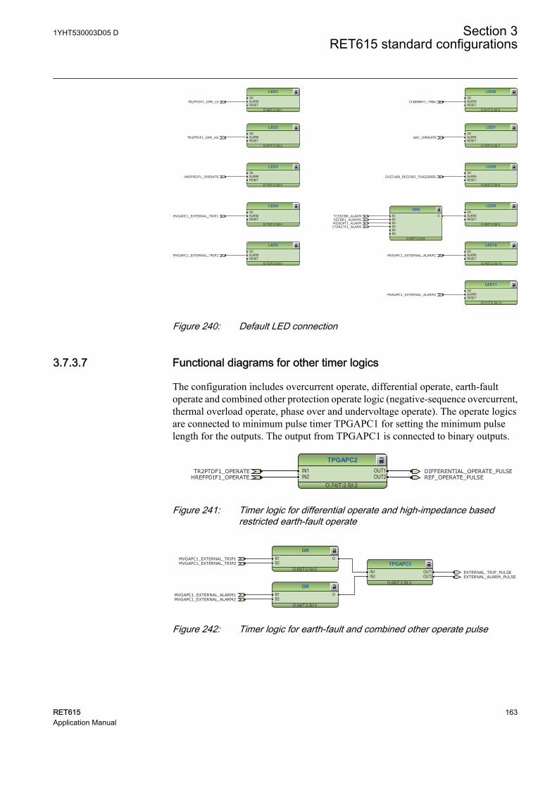
LED1
O:68|T:2.5|I:1
OKALARMRESET
LED2
O:67|T:2.5|I:2
OKALARMRESET
LED3
O:75|T:2.5|I:3
OKALARMRESET
LED4
O:73|T:2.5|I:4
OKALARMRESET
LED5
O:72|T:2.5|I:5
OKALARMRESET
HREFPDIF1_OPERATE
MVGAPC1_EXTERNAL_TRIP1
MVGAPC1_EXTERNAL_TRIP2
TR2PTDF1_OPR_LS
TR2PTDF1_OPR_HS
LED6
O:61|T:2.5|I:6
OKALARMRESET
LED7
O:70|T:2.5|I:7
OKALARMRESET
LED8
O:60|T:2.5|I:8
OKALARMRESET
LED9
O:56|T:2.5|I:9
OKALARMRESET
LED10
O:78|T:2.5|I:10
OKALARMRESET
LED11
O:71|T:2.5|I:11
OKALARMRESET
OR6
O:55|T:2.5|I:8
B1B2B3B4B5B6
O
CCBRBRF1_TRBU
MVGAPC1_EXTERNAL_ALARM2
MVGAPC1_EXTERNAL_ALARM1
CTSRCTF1_ALARMMDSOPT1_ALARM
TCSSCBR_ALARMSSCBR1_ALARMS
DISTURB_RECORD_TRIGGERED
ARC_OPERATE
GUID-30214BFE-31B9-4F7F-B59F-A8C20FDECCE9 V1 EN
Figure 240: Default LED connection
3.7.3.7 Functional diagrams for other timer logics
The configuration includes overcurrent operate, differential operate, earth-faultoperate and combined other protection operate logic (negative-sequence overcurrent,thermal overload operate, phase over and undervoltage operate). The operate logicsare connected to minimum pulse timer TPGAPC1 for setting the minimum pulselength for the outputs. The output from TPGAPC1 is connected to binary outputs.
TPGAPC2
O:74|T:2.5|I:2
IN1IN2
OUT1OUT2
DIFFERENTIAL_OPERATE_PULSEREF_OPERATE_PULSEHREFPDIF1_OPERATE
TR2PTDF1_OPERATE
GUID-118B5914-732C-4BD5-BFBD-911686F21034 V1 EN
Figure 241: Timer logic for differential operate and high-impedance basedrestricted earth-fault operate
TPGAPC3
O:66|T:2.5|I:3
IN1IN2
OUT1OUT2
OR
O:65|T:2.5|I:2
B1B2
O
OR
O:64|T:2.5|I:3
B1B2
O
EXTERNAL_TRIP_PULSEEXTERNAL_ALARM_PULSE
MVGAPC1_EXTERNAL_TRIP1MVGAPC1_EXTERNAL_TRIP2
MVGAPC1_EXTERNAL_ALARM2MVGAPC1_EXTERNAL_ALARM1
GUID-527F0D77-4FB2-47C6-AEB8-E2D29F906691 V1 EN
Figure 242: Timer logic for earth-fault and combined other operate pulse
1YHT530003D05 D Section 3RET615 standard configurations
RET615 163Application Manual
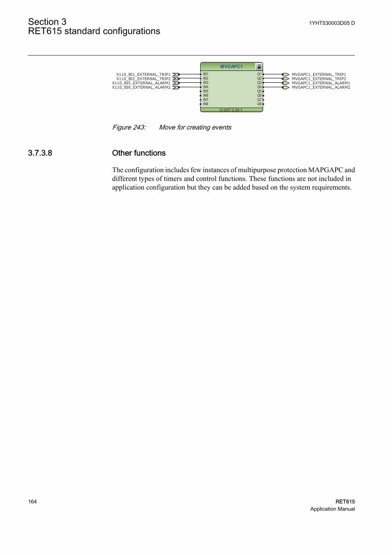
MVGAPC1
O:20|T:2.5|I:1
IN1IN2IN3IN4IN5IN6IN7IN8
Q1Q2Q3Q4Q5Q6Q7Q8
X110_BI6_EXTERNAL_ALARM2X110_BI5_EXTERNAL_ALARM1
MVGAPC1_EXTERNAL_TRIP1MVGAPC1_EXTERNAL_TRIP2
MVGAPC1_EXTERNAL_ALARM2MVGAPC1_EXTERNAL_ALARM1
X110_BI1_EXTERNAL_TRIP1X110_BI2_EXTERNAL_TRIP2
GUID-52647595-4784-4286-AD3D-2A2C00A086DE V1 EN
Figure 243: Move for creating events
3.7.3.8 Other functions
The configuration includes few instances of multipurpose protection MAPGAPC anddifferent types of timers and control functions. These functions are not included inapplication configuration but they can be added based on the system requirements.
Section 3 1YHT530003D05 DRET615 standard configurations
164 RET615Application Manual
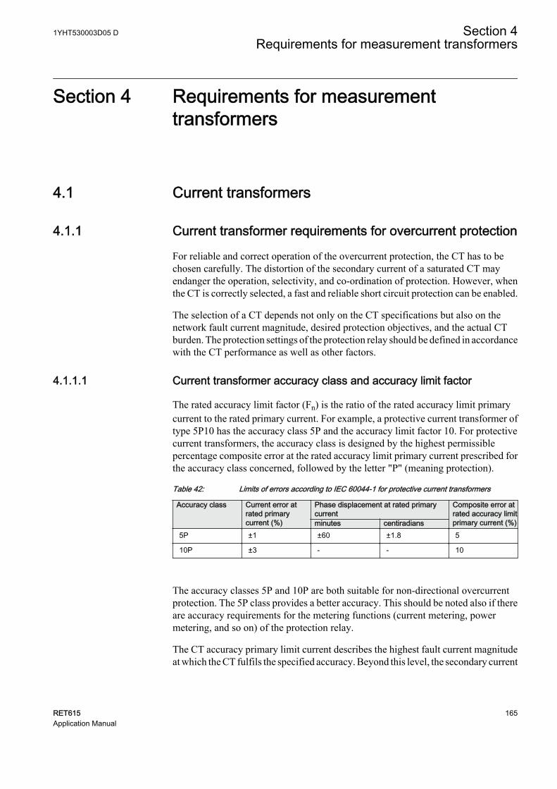
Section 4 Requirements for measurementtransformers
4.1 Current transformers
4.1.1 Current transformer requirements for overcurrent protection
For reliable and correct operation of the overcurrent protection, the CT has to bechosen carefully. The distortion of the secondary current of a saturated CT mayendanger the operation, selectivity, and co-ordination of protection. However, whenthe CT is correctly selected, a fast and reliable short circuit protection can be enabled.
The selection of a CT depends not only on the CT specifications but also on thenetwork fault current magnitude, desired protection objectives, and the actual CTburden. The protection settings of the protection relay should be defined in accordancewith the CT performance as well as other factors.
4.1.1.1 Current transformer accuracy class and accuracy limit factor
The rated accuracy limit factor (Fn) is the ratio of the rated accuracy limit primarycurrent to the rated primary current. For example, a protective current transformer oftype 5P10 has the accuracy class 5P and the accuracy limit factor 10. For protectivecurrent transformers, the accuracy class is designed by the highest permissiblepercentage composite error at the rated accuracy limit primary current prescribed forthe accuracy class concerned, followed by the letter "P" (meaning protection).
Table 42: Limits of errors according to IEC 60044-1 for protective current transformers
Accuracy class Current error atrated primarycurrent (%)
Phase displacement at rated primarycurrent
Composite error atrated accuracy limitprimary current (%)minutes centiradians
5P ±1 ±60 ±1.8 5
10P ±3 - - 10
The accuracy classes 5P and 10P are both suitable for non-directional overcurrentprotection. The 5P class provides a better accuracy. This should be noted also if thereare accuracy requirements for the metering functions (current metering, powermetering, and so on) of the protection relay.
The CT accuracy primary limit current describes the highest fault current magnitudeat which the CT fulfils the specified accuracy. Beyond this level, the secondary current
1YHT530003D05 D Section 4Requirements for measurement transformers
RET615 165Application Manual
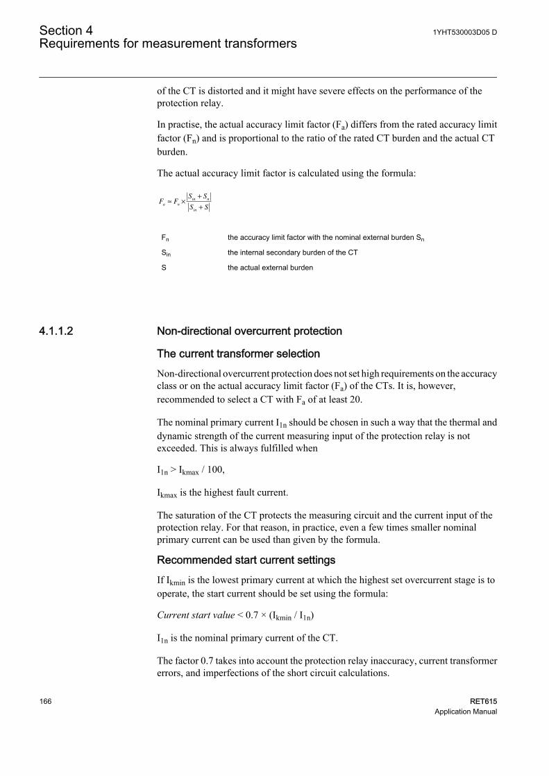
of the CT is distorted and it might have severe effects on the performance of theprotection relay.
In practise, the actual accuracy limit factor (Fa) differs from the rated accuracy limitfactor (Fn) and is proportional to the ratio of the rated CT burden and the actual CTburden.
The actual accuracy limit factor is calculated using the formula:
F FS S
S Sa n
in n
in
≈ ×
+
+
A071141 V1 EN
Fn the accuracy limit factor with the nominal external burden Sn
Sin the internal secondary burden of the CT
S the actual external burden
4.1.1.2 Non-directional overcurrent protection
The current transformer selectionNon-directional overcurrent protection does not set high requirements on the accuracyclass or on the actual accuracy limit factor (Fa) of the CTs. It is, however,recommended to select a CT with Fa of at least 20.
The nominal primary current I1n should be chosen in such a way that the thermal anddynamic strength of the current measuring input of the protection relay is notexceeded. This is always fulfilled when
I1n > Ikmax / 100,
Ikmax is the highest fault current.
The saturation of the CT protects the measuring circuit and the current input of theprotection relay. For that reason, in practice, even a few times smaller nominalprimary current can be used than given by the formula.
Recommended start current settingsIf Ikmin is the lowest primary current at which the highest set overcurrent stage is tooperate, the start current should be set using the formula:
Current start value < 0.7 × (Ikmin / I1n)
I1n is the nominal primary current of the CT.
The factor 0.7 takes into account the protection relay inaccuracy, current transformererrors, and imperfections of the short circuit calculations.
Section 4 1YHT530003D05 DRequirements for measurement transformers
166 RET615Application Manual
The adequate performance of the CT should be checked when the setting of the highset stage overcurrent protection is defined. The operate time delay caused by the CTsaturation is typically small enough when the overcurrent setting is noticeably lowerthan Fa.
When defining the setting values for the low set stages, the saturation of the CT doesnot need to be taken into account and the start current setting is simply according to theformula.
Delay in operation caused by saturation of current transformersThe saturation of CT may cause a delayed protection relay operation. To ensure thetime selectivity, the delay must be taken into account when setting the operate timesof successive protection relays.
With definite time mode of operation, the saturation of CT may cause a delay that isas long as the time constant of the DC component of the fault current, when the currentis only slightly higher than the starting current. This depends on the accuracy limitfactor of the CT, on the remanence flux of the core of the CT, and on the operate timesetting.
With inverse time mode of operation, the delay should always be considered as beingas long as the time constant of the DC component.
With inverse time mode of operation and when the high-set stages are not used, the ACcomponent of the fault current should not saturate the CT less than 20 times thestarting current. Otherwise, the inverse operation time can be further prolonged.Therefore, the accuracy limit factor Fa should be chosen using the formula:
Fa > 20 × Current start value / I1n
The Current start value is the primary start current setting of the protection relay.
4.1.1.3 Example for non-directional overcurrent protection
The following figure describes a typical medium voltage feeder. The protection isimplemented as three-stage definite time non-directional overcurrent protection.
1YHT530003D05 D Section 4Requirements for measurement transformers
RET615 167Application Manual
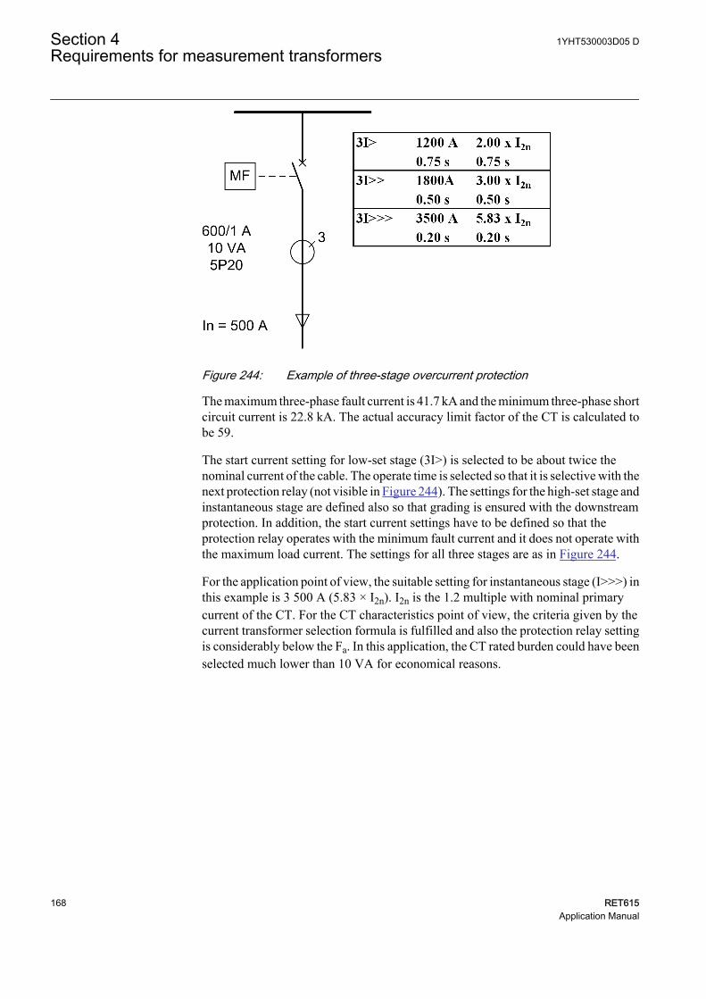
A071142 V1 EN
Figure 244: Example of three-stage overcurrent protection
The maximum three-phase fault current is 41.7 kA and the minimum three-phase shortcircuit current is 22.8 kA. The actual accuracy limit factor of the CT is calculated tobe 59.
The start current setting for low-set stage (3I>) is selected to be about twice thenominal current of the cable. The operate time is selected so that it is selective with thenext protection relay (not visible in Figure 244). The settings for the high-set stage andinstantaneous stage are defined also so that grading is ensured with the downstreamprotection. In addition, the start current settings have to be defined so that theprotection relay operates with the minimum fault current and it does not operate withthe maximum load current. The settings for all three stages are as in Figure 244.
For the application point of view, the suitable setting for instantaneous stage (I>>>) inthis example is 3 500 A (5.83 × I2n). I2n is the 1.2 multiple with nominal primarycurrent of the CT. For the CT characteristics point of view, the criteria given by thecurrent transformer selection formula is fulfilled and also the protection relay settingis considerably below the Fa. In this application, the CT rated burden could have beenselected much lower than 10 VA for economical reasons.
Section 4 1YHT530003D05 DRequirements for measurement transformers
168 RET615Application Manual
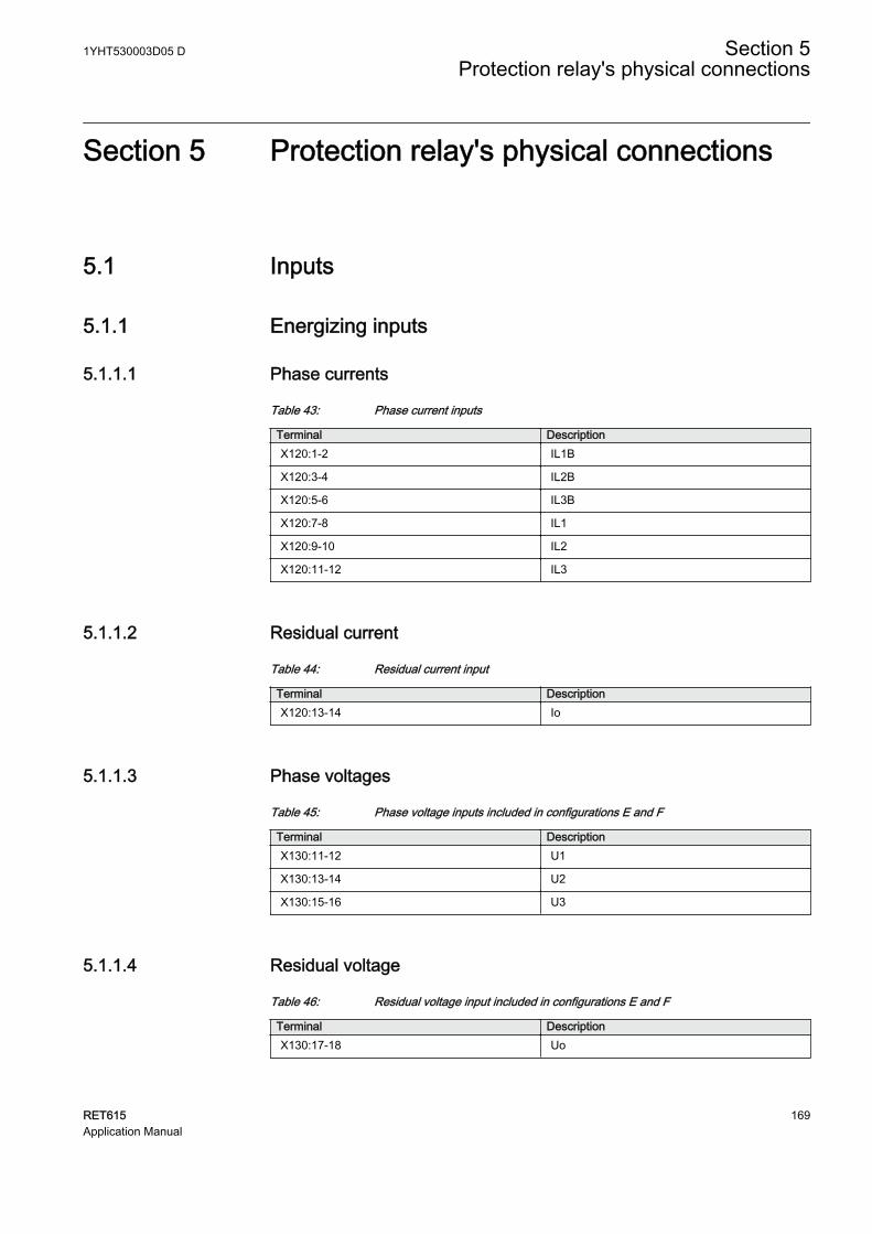
Section 5 Protection relay's physical connections
5.1 Inputs
5.1.1 Energizing inputs
5.1.1.1 Phase currents
Table 43: Phase current inputs
Terminal DescriptionX120:1-2 IL1B
X120:3-4 IL2B
X120:5-6 IL3B
X120:7-8 IL1
X120:9-10 IL2
X120:11-12 IL3
5.1.1.2 Residual current
Table 44: Residual current input
Terminal DescriptionX120:13-14 Io
5.1.1.3 Phase voltages
Table 45: Phase voltage inputs included in configurations E and F
Terminal DescriptionX130:11-12 U1
X130:13-14 U2
X130:15-16 U3
5.1.1.4 Residual voltage
Table 46: Residual voltage input included in configurations E and F
Terminal DescriptionX130:17-18 Uo
1YHT530003D05 D Section 5Protection relay's physical connections
RET615 169Application Manual
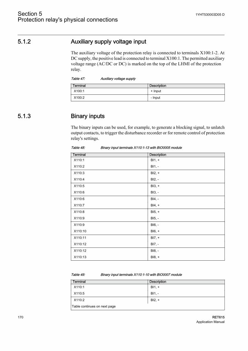
5.1.2 Auxiliary supply voltage input
The auxiliary voltage of the protection relay is connected to terminals X100:1-2. AtDC supply, the positive lead is connected to terminal X100:1. The permitted auxiliaryvoltage range (AC/DC or DC) is marked on the top of the LHMI of the protectionrelay.
Table 47: Auxiliary voltage supply
Terminal DescriptionX100:1 + Input
X100:2 - Input
5.1.3 Binary inputs
The binary inputs can be used, for example, to generate a blocking signal, to unlatchoutput contacts, to trigger the disturbance recorder or for remote control of protectionrelay's settings.
Table 48: Binary input terminals X110:1-13 with BIO0005 module
Terminal DescriptionX110:1 BI1, +
X110:2 BI1, -
X110:3 BI2, +
X110:4 BI2, -
X110:5 BI3, +
X110:6 BI3, -
X110:6 BI4, -
X110:7 BI4, +
X110:8 BI5, +
X110:9 BI5, -
X110:9 BI6, -
X110:10 BI6, +
X110:11 BI7, +
X110:12 BI7, -
X110:12 BI8, -
X110:13 BI8, +
Table 49: Binary input terminals X110:1-10 with BIO0007 module
Terminal DescriptionX110:1 BI1, +
X110:5 BI1, -
X110:2 BI2, +
Table continues on next page
Section 5 1YHT530003D05 DProtection relay's physical connections
170 RET615Application Manual
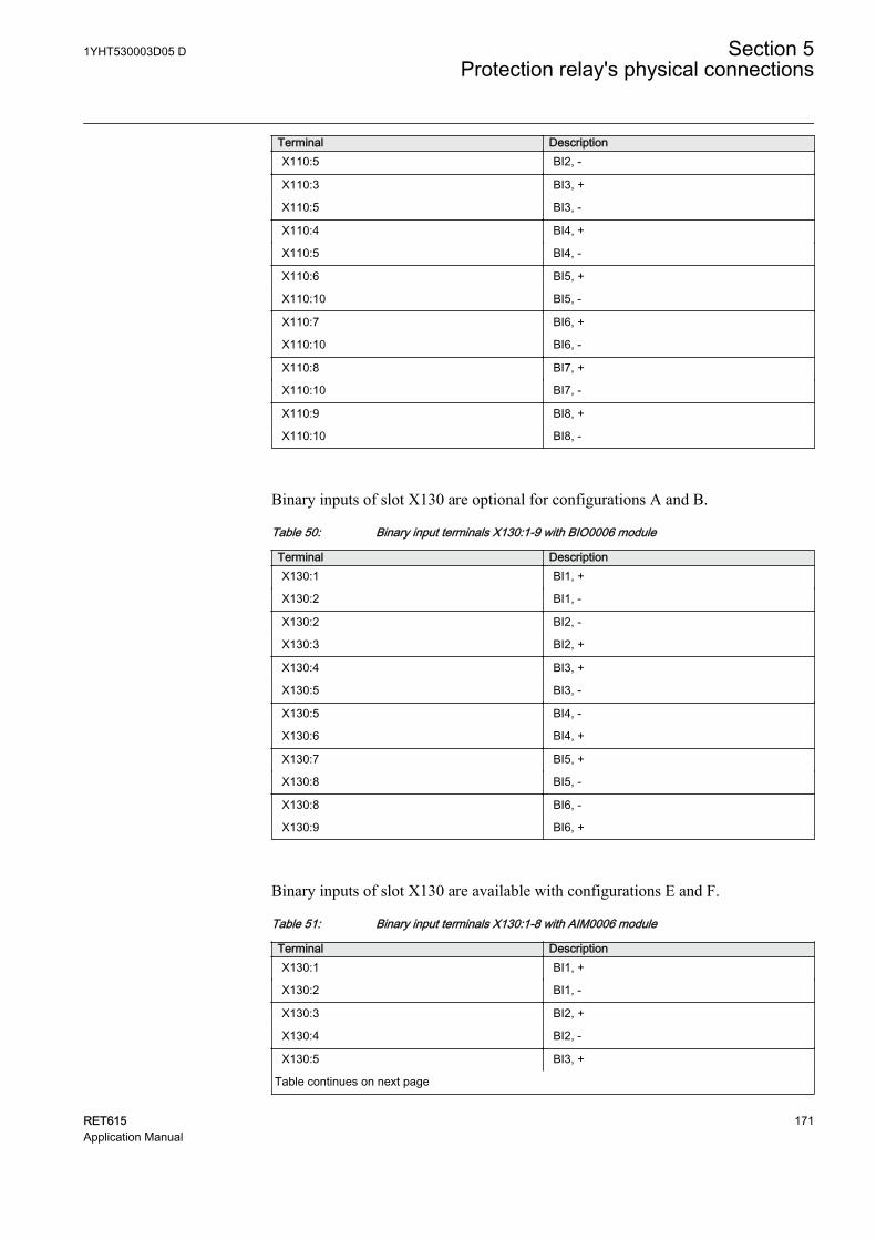
Terminal DescriptionX110:5 BI2, -
X110:3 BI3, +
X110:5 BI3, -
X110:4 BI4, +
X110:5 BI4, -
X110:6 BI5, +
X110:10 BI5, -
X110:7 BI6, +
X110:10 BI6, -
X110:8 BI7, +
X110:10 BI7, -
X110:9 BI8, +
X110:10 BI8, -
Binary inputs of slot X130 are optional for configurations A and B.
Table 50: Binary input terminals X130:1-9 with BIO0006 module
Terminal DescriptionX130:1 BI1, +
X130:2 BI1, -
X130:2 BI2, -
X130:3 BI2, +
X130:4 BI3, +
X130:5 BI3, -
X130:5 BI4, -
X130:6 BI4, +
X130:7 BI5, +
X130:8 BI5, -
X130:8 BI6, -
X130:9 BI6, +
Binary inputs of slot X130 are available with configurations E and F.
Table 51: Binary input terminals X130:1-8 with AIM0006 module
Terminal DescriptionX130:1 BI1, +
X130:2 BI1, -
X130:3 BI2, +
X130:4 BI2, -
X130:5 BI3, +
Table continues on next page
1YHT530003D05 D Section 5Protection relay's physical connections
RET615 171Application Manual
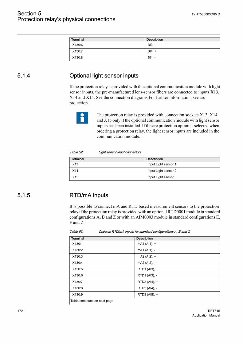
Terminal DescriptionX130:6 BI3, -
X130:7 BI4, +
X130:8 BI4, -
5.1.4 Optional light sensor inputs
If the protection relay is provided with the optional communication module with lightsensor inputs, the pre-manufactured lens-sensor fibers are connected to inputs X13,X14 and X15. See the connection diagrams.For further information, see arcprotection.
The protection relay is provided with connection sockets X13, X14and X15 only if the optional communication module with light sensorinputs has been installed. If the arc protection option is selected whenordering a protection relay, the light sensor inputs are included in thecommunication module.
Table 52: Light sensor input connectors
Terminal DescriptionX13 Input Light sensor 1
X14 Input Light sensor 2
X15 Input Light sensor 3
5.1.5 RTD/mA inputs
It is possible to connect mA and RTD based measurement sensors to the protectionrelay if the protection relay is provided with an optional RTD0001 module in standardconfigurations A, B and Z or with an AIM0003 module in standard configurations E,F and Z.
Table 53: Optional RTD/mA inputs for standard configurations A, B and Z
Terminal DescriptionX130:1 mA1 (AI1), +
X130:2 mA1 (AI1), -
X130:3 mA2 (AI2), +
X130:4 mA2 (AI2), -
X130:5 RTD1 (AI3), +
X130:6 RTD1 (AI3), -
X130:7 RTD2 (AI4), +
X130:8 RTD2 (AI4), -
X130:9 RTD3 (AI5), +
Table continues on next page
Section 5 1YHT530003D05 DProtection relay's physical connections
172 RET615Application Manual
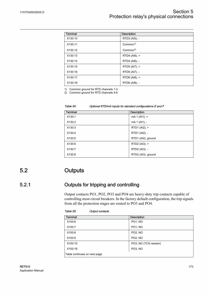
Terminal DescriptionX130:10 RTD3 (AI5), -
X130:11 Common1)
X130:12 Common2)
X130:13 RTD4 (AI6), +
X130:14 RTD4 (AI6), -
X130:15 RTD5 (AI7), +
X130:16 RTD5 (AI7), -
X130:17 RTD6 (AI8), +
X130:18 RTD6 (AI8), -
1) Common ground for RTD channels 1-32) Common ground for RTD channels 4-6
Table 54: Optional RTD/mA inputs for standard configurations E and F
Terminal DescriptionX130:1 mA 1 (AI1), +
X130:2 mA 1 (AI1), -
X130:3 RTD1 (AI2), +
X130:4 RTD1 (AI2), -
X130:5 RTD1 (AI2), ground
X130:6 RTD2 (AI3), +
X130:7 RTD2 (AI3), -
X130:8 RTD2 (AI3), ground
5.2 Outputs
5.2.1 Outputs for tripping and controlling
Output contacts PO1, PO2, PO3 and PO4 are heavy-duty trip contacts capable ofcontrolling most circuit breakers. In the factory default configuration, the trip signalsfrom all the protection stages are routed to PO3 and PO4.
Table 55: Output contacts
Terminal DescriptionX100:6 PO1, NO
X100:7 PO1, NO
X100:8 PO2, NO
X100:9 PO2, NO
X100:15 PO3, NO (TCS resistor)
X100:16 PO3, NO
Table continues on next page
1YHT530003D05 D Section 5Protection relay's physical connections
RET615 173Application Manual
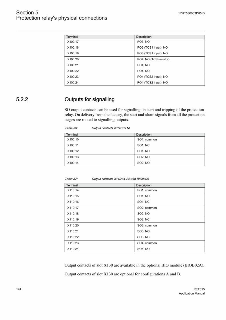
Terminal DescriptionX100:17 PO3, NO
X100:18 PO3 (TCS1 input), NO
X100:19 PO3 (TCS1 input), NO
X100:20 PO4, NO (TCS resistor)
X100:21 PO4, NO
X100:22 PO4, NO
X100:23 PO4 (TCS2 input), NO
X100:24 PO4 (TCS2 input), NO
5.2.2 Outputs for signalling
SO output contacts can be used for signalling on start and tripping of the protectionrelay. On delivery from the factory, the start and alarm signals from all the protectionstages are routed to signalling outputs.
Table 56: Output contacts X100:10-14
Terminal DescriptionX100:10 SO1, common
X100:11 SO1, NC
X100:12 SO1, NO
X100:13 SO2, NO
X100:14 SO2, NO
Table 57: Output contacts X110:14-24 with BIO0005
Terminal DescriptionX110:14 SO1, common
X110:15 SO1, NO
X110:16 SO1, NC
X110:17 SO2, common
X110:18 SO2, NO
X110:19 SO2, NC
X110:20 SO3, common
X110:21 SO3, NO
X110:22 SO3, NC
X110:23 SO4, common
X110:24 SO4, NO
Output contacts of slot X130 are available in the optional BIO module (BIOB02A).
Output contacts of slot X130 are optional for configurations A and B.
Section 5 1YHT530003D05 DProtection relay's physical connections
174 RET615Application Manual
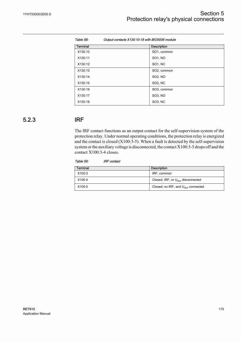
Table 58: Output contacts X130:10-18 with BIO0006 module
Terminal DescriptionX130:10 SO1, common
X130:11 SO1, NO
X130:12 SO1, NC
X130:13 SO2, common
X130:14 SO2, NO
X130:15 SO2, NC
X130:16 SO3, common
X130:17 SO3, NO
X130:18 SO3, NC
5.2.3 IRF
The IRF contact functions as an output contact for the self-supervision system of theprotection relay. Under normal operating conditions, the protection relay is energizedand the contact is closed (X100:3-5). When a fault is detected by the self-supervisionsystem or the auxiliary voltage is disconnected, the contact X100:3-5 drops off and thecontact X100:3-4 closes.
Table 59: IRF contact
Terminal DescriptionX100:3 IRF, common
X100:4 Closed; IRF, or Uaux disconnected
X100:5 Closed; no IRF, and Uaux connected
1YHT530003D05 D Section 5Protection relay's physical connections
RET615 175Application Manual

176
Section 6 Glossary
100BASE-FX A physical medium defined in the IEEE 802.3 Ethernetstandard for local area networks (LANs) that uses fiberoptic cabling
100BASE-TX A physical medium defined in the IEEE 802.3 Ethernetstandard for local area networks (LANs) that usestwisted-pair cabling category 5 or higher with RJ-45connectors
615 series Series of numerical protection and control relays forprotection and supervision applications of utilitysubstations, and industrial switchgear and equipment
AC Alternating currentAI Analog inputASCII American Standard Code for Information InterchangeBCD Binary coded decimalBI Binary inputBIO Binary input and outputBO Binary outputCB Circuit breakerCT Current transformerDAN Doubly attached nodeDC 1. Direct current
2. Disconnector3. Double command
DPC Double-point controlEMC Electromagnetic compatibilityEthernet A standard for connecting a family of frame-based
computer networking technologies into a LANFIFO First in, first outFTP File transfer protocolFTPS FTP SecureGOOSE Generic Object-Oriented Substation EventHMI Human-machine interfaceHSO High-speed output
1YHT530003D05 D Section 6Glossary
RET615 177Application Manual
HSR High-availability seamless redundancyHTTPS Hypertext Transfer Protocol SecureHV High voltageI/O Input/outputIEC International Electrotechnical CommissionIEC 60870-5-103 1. Communication standard for protective equipment
2. A serial master/slave protocol for point-to-pointcommunication
IEC 61850 International standard for substation communicationand modeling
IEC 61850-8-1 A communication protocol based on the IEC 61850standard series
IEC 61850-9-2 A communication protocol based on the IEC 61850standard series
IEC 61850-9-2 LE Lite Edition of IEC 61850-9-2 offering process businterface
IEEE 1686 Standard for Substation Intelligent Electronic Devices'(IEDs') Cyber Security Capabilities
IP address A set of four numbers between 0 and 255, separated byperiods. Each server connected to the Internet isassigned a unique IP address that specifies the locationfor the TCP/IP protocol.
IRIG-B Inter-Range Instrumentation Group's time code formatB
LAN Local area networkLC Connector type for glass fiber cable, IEC 61754-20LCD Liquid crystal displayLE Light EditionLED Light-emitting diodeLHMI Local human-machine interfaceLSB Least significant bitLV Low voltageMAC Media access controlMCB Miniature circuit breakerMMS 1. Manufacturing message specification
2. Metering management system
Section 6 1YHT530003D05 DGlossary
178 RET615Application Manual
Modbus A serial communication protocol developed by theModicon company in 1979. Originally used forcommunication in PLCs and RTU devices.
Modbus TCP/IP Modbus RTU protocol which uses TCP/IP and Ethernetto carry data between devices
MSB Most significant bitNC Normally closedNO Normally openPCM600 Protection and Control IED ManagerPO Power outputPRP Parallel redundancy protocolPTP Precision Time ProtocolRET615 Transformer protection and control relayRIO600 Remote I/O unitRJ-45 Galvanic connector typeRSTP Rapid spanning tree protocolRTD Resistance temperature detectorRTU Remote terminal unitSAN Single attached nodeSingle-line diagram Simplified notation for representing a three-phase
power system. Instead of representing each of threephases with a separate line or terminal, only oneconductor is represented.
SLD Single-line diagramSMV Sampled measured valuesSNTP Simple Network Time ProtocolSO Signal outputTCS Trip-circuit supervisionWAN Wide area networkWHMI Web human-machine interface
1YHT530003D05 D Section 6Glossary
RET615 179Application Manual

180

181

ABBNanjing SAC Power Grid Automation Co.,Ltd.No.39 Shuige Road, Jiangning District211153 Nanjing, ChinaPhone +86 25 69832000Fax +86 25 69833000
www.abb.com/substationautomation
—
© Copyright 2019 ABB. All rights reserved. 1YH
T53
00
03D
05
D
![FXCPU Structured Programming Manual [Application Functions] · FXCPU Structured Programming Manual [Application Functions] FXCPU Structured Programming Manual [Application Functions]](https://img.pdfslide.net/doc/110x75/5f7c3a0ec7c4c4492f38781e/fxcpu-structured-programming-manual-application-functions-fxcpu-structured-programming.jpg)