Embed Size (px)
Citation preview
Application Note AP-000 04/05/CW
RAE Systems by Honeywell 877-723-2878 raesystems.com 1
RAE SYSTEMS PID TRAINING OUTLINEWHAT IS A PID?
A PID (photoionization detector) measures VOCs and other toxic gases in low concentrations from ppb (parts per billion) up to 10,000 ppm (parts per million or 1% by volume). A PID is a very sensitive broad-spectrum monitor, like a low-level LEL monitor. RAE Systems’ improvements in PID technology have miniaturized and “ruggedized” PIDs allowing them to provide new and innovative monitoring solutions for:
• LEL Measurements. PIDs provide a more reliable means of measuring LEL in applications like Jet Fuel and Turpentine vapors (see AP-200, 204, 219).
• Ammonia. See AP-201.
• HazMat. Hazardous Materials Response (see AP-203).
• Heat Transfer Fluids. See AP-205.
• Arson. See AP-207.
• Industrial Hygiene. To help determine chemical exposures (see AP-211).
• Indoor Air Quality. See AP-212.
• Environmental. Residual soil, air, or water contamination (see AP-214).
• Safety. Confined Space Entry (see AP-211).
• Maintenance. Leak detection and fugitive emissions monitoring (see AP-214).
• Domestic Preparedness. See AP-216.
• Clan Labs. See AP-220. How does a PID Work?
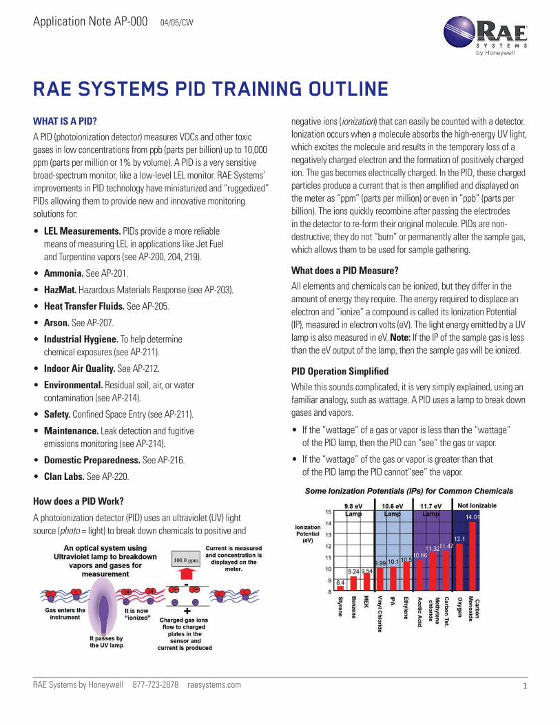
A photoionization detector (PID) uses an ultraviolet (UV) light source (photo = light) to break down chemicals to positive and
negative ions (ionization) that can easily be counted with a detector. Ionization occurs when a molecule absorbs the high-energy UV light, which excites the molecule and results in the temporary loss of a negatively charged electron and the formation of positively charged ion. The gas becomes electrically charged. In the PID, these charged particles produce a current that is then amplified and displayed on the meter as “ppm” (parts per million) or even in “ppb” (parts per billion). The ions quickly recombine after passing the electrodes in the detector to re-form their original molecule. PIDs are non-destructive; they do not “burn” or permanently alter the sample gas, which allows them to be used for sample gathering.
What does a PID Measure?
All elements and chemicals can be ionized, but they differ in the amount of energy they require. The energy required to displace an electron and “ionize” a compound is called its Ionization Potential (IP), measured in electron volts (eV). The light energy emitted by a UV lamp is also measured in eV. Note: If the IP of the sample gas is less than the eV output of the lamp, then the sample gas will be ionized.
PID Operation Simplified
While this sounds complicated, it is very simply explained, using an familiar analogy, such as wattage. A PID uses a lamp to break down gases and vapors.
• If the “wattage” of a gas or vapor is less than the “wattage” of the PID lamp, then the PID can “see” the gas or vapor.
• If the “wattage” of the gas or vapor is greater than that of the PID lamp the PID cannot“see” the vapor.
Application Note AP-000 04/05/CW
RAE Systems by Honeywell 877-723-2878 raesystems.com 2
Therefore, a PID with a “75-watt” lamp could see a 50-watt gas but could not “see” an 85watt gas. Although we used wattage for this explanation, energy for PIDs is expressed in Electron Volts, or eV, and is known as the Ionization Potential (IP) for a particular gas or vapor. Ionization Potential is a measure of the bond strength of a gas, or how well it is “built.” Benzene has an IP of 9.24 eV and can be seen by a “standard” 10.6 eV lamp. Methylene Chloride has an IP of 11.32 eV and can only be seen by an 11.7 eV lamp. Carbon monoxide has an IP of 14.01 eV and cannot be ionized by a PID lamp.
IPs can be found in the NIOSH Pocket Guide, PID manufacturer literature and in many chemical texts. RAE Systems uses a NIST (National Institute of Science & Technology) Database containing over 11,000 compounds to determine IPs of new compounds to be measured (see RAE Systems Technical Note TN-106: Correction Factors, Ionization Energies and Calibration Characteristics).
WHAT DOES A PID MEASURE?
The largest group of compounds measured by a PID are the Organics: compounds containing Carbon (C) atoms. These include:
• Aromatics. Compounds containing a benzene ring including benzene, toluene, ethyl benzene and xylene.
• Ketones and aldehydes. Compounds with a C=O bond including acetone, methyl ethyl ketone (MEK) and acetaldehyde.
• Amines and amides. Carbon compounds containing nitrogen, like diethylamine.
• Chlorinated hydrocarbons. Trichloroethylene (TCE), perchloroethylene (PERC)
• Sulfur compounds. Mercaptans, sulfides
• Unsaturated hydrocarbons. Like butadiene and isobutylene
• Alcohols. Like isopropanol (IPA) and ethanol
• Saturated hydrocarbons. Like butane and octane
In addition to organic compounds, PIDs can be used to measure some Inorganics. These are compounds without carbon and include:
• Ammonia
• Semiconductor gases: arsine, phosphine
• Hydrogen sulfide
• Nitric oxide
• Bromine and iodine
WHAT PIDS DO NOT MEASURE
• Radiation
• Air (N2, O2, CO2, H2O)
• Common toxics (CO, HCN, SO2)
• Natural Gas (methane, ethane)
• Acid gases (HCl, HF, HNO3)
• Others: Freons, ozone (O3), hydrogen peroxide
• Non-volatiles: PCBs, greases
9.8 & 10.6 EV VERSUS 11.7 EV PID LAMPS
At first glance, it may appear that to measure the broadest range of gases with a PID, an 11.7eV lamp should be used instead of a 10.6eV lamp. However, the following must be considered:
• 9.8 and 10.6 are more specific. Lower IP means that they “see” fewer chemicals.
• 9.8 and 10.6 last a few years. About the same lifetime and cost as a CO sensor.
• 9.8 and 10.6 are more sensitive. 11.7 eV lamps provide lower resolution: The lithium fluoride crystal in the 11.7 eV lamp does not allow as much light energy through, effectively making the 11.7 eV lamp “dimmer” than the 10.6eV lamp. Less energy transmitted means less ionization taking place, which reduces the potential resolution. Essentially a 10.6 eV lamp is 10 times more powerful than an 11.7 eV lamp. Therefore, for best accuracy, it is not recommended to use 11.7 eV lamps for applications requiring very high sensitivity. Examples include formaldehyde, which has an OSHA TWA of just 0.75 ppm.
• 11.7 eV lamps have a shorter life than 9.8 or 10.6. All 11.7 eV lamps (including those made by RAE’s competitors) have a window made of Lithium Fluoride to transmit the high energy UV light. Lithium fluoride is harder to seal to the lamp glass, is very hygroscopic and readily absorbs water from air even when not in use. This causes the window to swell and decreases the amount of light transmitted through the window. Lithium fluoride also is degraded by UV light, the more the instrument is used the greater the damage. These factors contribute to a shortened lamp life. While a 10.6 eV lamp can last 24 to 36 months, an 11.7 eV lamp typically lasts only two to six months.
• 11.7 eV bulbs should only be used when compounds with IPs over 10.6 eV are expected. Examples include methylene chloride, chloroform, and carbon tetrachloride.
Application Note AP-000 04/05/CW
RAE Systems by Honeywell 877-723-2878 raesystems.com 3
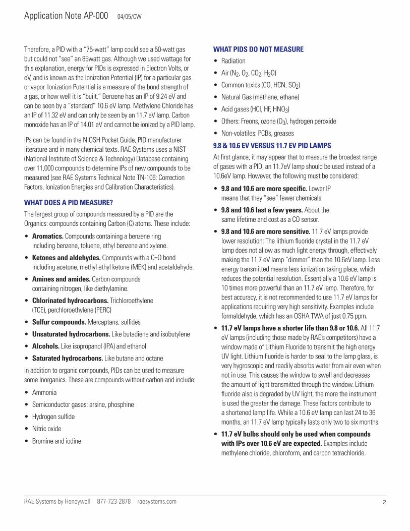
• Least expensive and easiest to change 11.7 eV lamp. While RAE Systems’ 11.7 eV lamp is the least expensive in the PID market (with some 11.7 eV lamps costing as much as $500), they still are more expensive than a 10.eV lamp. Unlike some PIDs that require expensive conversion kits, RAE Systems’ 11.7 eV lamps drop right into our instruments. No modifications are necessary. You change the lamp, recalibrate and measure.
• Long-Term Storage of 11.7 eV Lamps. As a solution to the problem of a short lifetime for 11.7 eV lamps, RAE Systems offers them packaged in sealed glass ampoules. The gas in the ampoule is the same as in the lamp. The ampoule effectively packages a new lamp in a lamp. When the 11.7 eV lamp is required, the ampoule is broken, the lamp removed and inserted into the PID. This ampoule is only available for the 1/4” lamps used in the MultiRAE and ToxiRAE PIDs.
• Extending 11.7eV Lamp Life. 11.7eV lamp life can be extended if the lamp is stored in a desiccant environment (in or out of the PID) between uses. This can simply be a container containing silica gel drying packs like those that ship with electronic and camera equipment. It is not recommended to store MultiRAE Pluses in a desiccant environment because this decreases thelife of its electrochemical sensors.
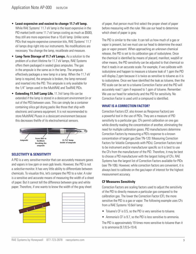
SELECTIVITY & SENSITIVITY
A PID is a very sensitive monitor that can accurately measure gases and vapors in low ppm or even ppb levels. However, the PID is not a selective monitor. It has very little ability to differentiate between chemicals. To visualize this, let’s compare the PID to a ruler. A ruler is a sensitive and accurate means of measuring the width of a sheet of paper. But it cannot tell the difference between gray and white paper. Therefore, if one wants to know the width of the gray sheet
of paper, that person must first select the proper sheet of paper before measuring with the ruler. We use our head to determine which sheet of paper is gray.
The PID is similar to the ruler. It can tell us how much of a gas or vapor is present, but we must use our head to determine the exact gas or vapor present. When approaching an unknown chemical release, the PID is set to its calibration gas of isobutylene. Once the chemical is identified by means of placard, manifest, waybill or other means, the PID sensitivity can be adjusted to that chemical so that it reads in an accurate scale. For example, if we calibrate with isobutylene and happen to measure a toluene leak of 1 ppm the PID will display 2 ppm because it is twice as sensitive to toluene as it is to isobutylene. Once we have identified the leak as toluene, then the PID scale can be set to a toluene Correction Factor and the PID will accurately read 1 ppm if exposed to 1 ppm of toluene. Remember: We use our head for selectivity and the PID for sensitivity. No Correction Factor is used until a compound is identified.
WHAT IS A CORRECTION FACTOR?
Correction Factors (CF, also known as Response Factors) are a powerful tool in the use of PIDs. They are a measure of PID sensitivity to a particular gas. CFs permit calibration on one gas while directly reading the concentration of another, eliminating the need for multiple calibration gases. PID manufacturers determine Correction Factors by measuring a PID’s response to a known concentration of target gas (See TN-120: Measuring Correction Factors for Volatile Compounds with PIDs). Correction Factors tend to be instrument and/or manufacturer specific so it is best to use the CFs from the manufacturer of the PID. Therefore, it may be best to choose a PID manufacturer with the largest listing of CFs. RAE Systems has the largest list of Correction Factors available for PIDs (see TN-106). However, while correction factors are convenient, it is always best to calibrate on the gas/vapor of interest for the highest measurement accuracy.
CF Measures Sensitivity
Correction Factors are scaling factors used to adjust the sensitivity of the PID to directly measure a particular gas compared to the calibration gas. The lower the Correction Factor (CF), the more sensitive the PID is a gas or vapor. The following example uses CFs from a RAE Systems 10.6eV lamp:
• Toluene’s CF is 0.5, so the PID is very sensitive to toluene.
• Ammonia’s CF is 9.7, so the PID is less sensitive to ammonia.
The PID is approximately 19 times more sensitive to toluene than it is to ammonia (9.7/0.5=19.4).
Application Note AP-000 04/05/CW
RAE Systems by Honeywell 877-723-2878 raesystems.com 4
Guidelines for using Correction Factors
1. If a PID is going to be used to measure a very toxic chemical, the PID should be very sensitive to that chemical. Therefore, if the chemical has an exposure limit of 10 ppm or less, a PID is an appropriate tool for personal safety decisions if the chemical’s CF is less than 1.0 (e.g., benzene has an exposure limit of 1 ppm and a CF of 0.5).
2. If a chemical is not extremely toxic, then the PID doesn’t need to be as sensitive to it. Therefore, if the chemical has an exposure limit of over 10 ppm, a PID is an appropriate tool for personal safety decisions if the chemical’s CF is less than 10. (e.g.: ammonia has an exposure limit of 25 ppm and a CF of 9.7).
3. If the chemical’s CF is greater than 10 PIDs are still appropriate as gross leak detectors (e.g., ethylene oxide has a CF of 13 with a 10.6 lamp) and are only appropriate for personal safety decisions for chemicals with very high exposure limits.
Microprocessor PIDs, like the MiniRAE 2000 and ppbRAE, can automatically store and apply over 100 CFs.
CF Example: Toluene
• If a PID reads 100 ppm of isobutylene units in a Toluene atmosphere, then the actual concentration is 50 ppm toluene units:
0.5CF x 100 ppmiso = 50 ppmtoluene
CF Example: Ammonia
• If a PID reads 100 ppm of isobutylene units in an Ammonia atmosphere, then the actual concentration is 970 ppm ammonia units:
9.7CF x 100 ppmiso= 970 ppmammonia
How to Determine if a PID can Measure a Particular Gas
1. Is the IP of the gas less than the eV output of the lamp?
• Yes: Go to step 2.
• No: Select a higher energy lamp. If none available, then the PID cannot measure that gas.
• Don’t Know: Most PID manufacturers can help.
2. Is the CF less than 10?
• Yes: A PID is an appropriate way of measuring that gas.
• No: A PID is not an accurate means of measuring that gas, but it could still be a good way of gross measurement like leak detection.
• Don’t Know: Call RAE Systems at 877-723-2878.
Why Calibrate with Isobutylene?
Isobutylene has been used to calibrate PIDs because its responsiveness is about at the midpoint in the range of sensitivity of PIDs. It is relatively easy to obtain and is non-toxic and non-flammable at the low concentrations used for calibration. For years PIDs were calibrated with benzene, but because of its carcinogenic properties benzene calibrations have been phased out. While PIDs are typically calibrated with isobutylene, they can be calibrated with any ionizable gas. For example, if a PID is to be used to measure only vinyl chloride, the PID can be calibrated directly with a know concentration of vinyl chloride.
HOW HAS RAE SYSTEMS ADVANCED PID LAMPS?
Competitors’ Electrode Discharge lamps
A high-energy electric current is conducted to a gas mixture via electrodes. The electrodes directly excite the gas mixture to produce light. A form of vacuum (or radio) tube these “valve electronic” devices have a number of issues.
• Internal contamination. Electrode discharge lamps suffer from eroding electrodes that deposit on the lamp and reduce lamp output. We see this on fluorescent tubes when the ends darken as the lamp ages. While a 10% drop in light output is not detectable by the human eye, it can severely affect instrument readings and require more frequent calibration and ultimately reducing lamp life.
• Metal-to-glass interfaces are prone to failure. We often screw incandescent lightbulbs in too tight and they break loose from their base. This is a good example of metal-to-glass interface failure. It is difficult to bond glass to metal, and every metal to glass interface is a potential failure point. Like incandescent lightbulbs, metal-to-glass interfaces in electrode discharge lamps are potential failure points.
• High power draw. Electrode discharge lamps have a high power draw compared to electrodeless discharge lamps. These several-watt lamps waste energy as heat, requiring large batteries, and are not as easy to use or carry.
Application Note AP-000 04/05/CW
RAE Systems by Honeywell 877-723-2878 raesystems.com 5
• High RFI (radio-frequency interference). We often get a hum on our personal radios when working near luorescent lights. Electrode discharge lamps suffer from the same high RFI problem.
Competitors’ RF-Excited Lamps
The electrodeless lamp is put into a coil of wire and is subjected to high-frequency excitation energy (12 to 14MHz) to generate a glow discharge in the lamp.
• High power consumption
• Subject to RFI. High-frequency excitation energy is affected by radios and power lines because a radio-frequency (RF) coil can act as an antenna.
• Higher maintenance. RF coupling efficiency requires a perfectly tuned driving circuit. These complex circuits require constant tuning.
ADVANTAGES OF RAE SYSTEMS’ ELECTRODELESS LAMP
The RAE Systems lamp is put into a low-frequency RF field, which indirectly excites the gas in it to glow. This is like using a microwave oven to cook food. Both the lamp and the food are excited to radiate (heat for the food, light for the lamp) by an external field.
• Extremely low power draw: RAE Systems’ electrodeless discharge lamps have an extremely low power draw. This results in a cool lamp that uses small batteries. Low power draw is a key factor in decreasing the size of RAE Systems PIDs.
• No internal contamination. Electrodeless discharge lamps are externally excited and have no metal in them to damage, erode or migrate.
• Extremely rugged. Because they reduce or eliminate metal to glass interfaces electrodeless discharge lamps are extremely rugged. RAE Systems has totally eliminated all metal-glass interfaces in its 10.6 eV lamp. The magnesium fluoride crystal is welded to the lamp’s glass.
• Virtually no RFI or EMI. RAE lamps are powered by a low-frequency electrical field. Compared with electrode discharge lamps, this method virtually eliminates RFI and EMI (electromagnetic interference).
HOW HAS RAE SYSTEMS ADVANCED PID SENSORS?
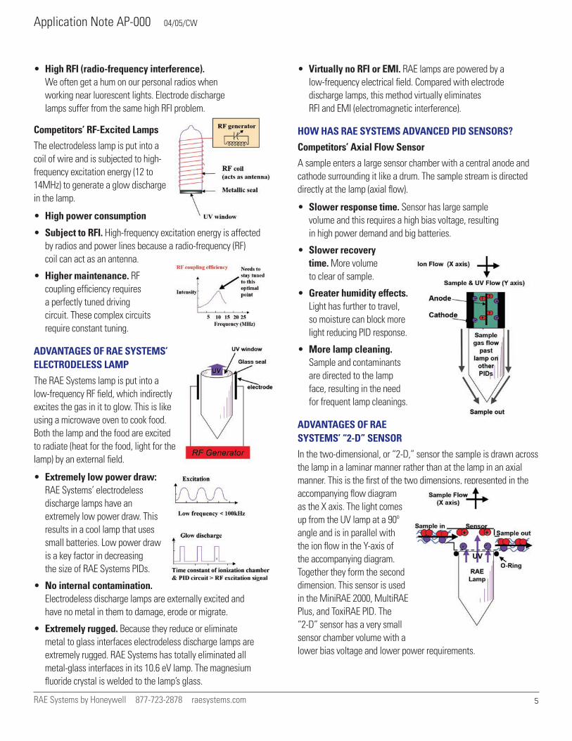
Competitors’ Axial Flow Sensor
A sample enters a large sensor chamber with a central anode and cathode surrounding it like a drum. The sample stream is directed directly at the lamp (axial flow).
• Slower response time. Sensor has large sample volume and this requires a high bias voltage, resulting in high power demand and big batteries.
• Slower recovery time. More volume to clear of sample.
• Greater humidity effects. Light has further to travel, so moisture can block more light reducing PID response.
• More lamp cleaning. Sample and contaminants are directed to the lamp face, resulting in the need for frequent lamp cleanings.
ADVANTAGES OF RAE SYSTEMS’ “2-D” SENSOR
In the two-dimensional, or “2-D,” sensor the sample is drawn across the lamp in a laminar manner rather than at the lamp in an axial manner. This is the first of the two dimensions, represented in the accompanying flow diagram as the X axis. The light comes up from the UV lamp at a 90º angle and is in parallel with the ion flow in the Y-axis of the accompanying diagram. Together they form the second dimension. This sensor is used in the MiniRAE 2000, MultiRAE Plus, and ToxiRAE PID. The “2-D” sensor has a very small sensor chamber volume with a lower bias voltage and lower power requirements.
Application Note AP-000 04/05/CW
RAE Systems by Honeywell 877-723-2878 raesystems.com 6
• Fast Response. Placing the sensor directly on top of the lamp minimizes the sample chamber volume and with the O-ring seal provides nearly instantaneous response times as good as less than 3 sec. to 90% to 2000 ppm. This extremely fast response means more accurate and quicker leak, or “hot spot,” detection. To demonstrate this benefit of the MiniRAE, take a non-waterbased marking pen like a Sharpie or a white-board marker and make a small line on a piece of paper. The MiniRAE will easily “find” this line in seconds.
• Fast recovery. Because the sample flow travels across rather than directly towards the lamp face, the top of the lamp chamber can be sealed with an O-ring. This helps to decrease response and recovery times of RAE Systems PIDs because it prevents sample gas from accumulating around the lamp. Fast recovery means that the reading quickly returns to zero. Fast recovery between samples means that multiple sampling (like headspace samples) proceeds much faster than with any other PID. Fast recovery also provides for succinct detection of vapor leaks.
• Low humidity response. Laminar flow and placing the sensor on top of the lamp face maximize the exposure of the gas stream to UV light. This drastically reduces humidity and non-ionizing gas interference in RAE Systems PIDs. Humidity molecules absorb UV in much the same way as fog absorbs light from your car headlights when you drive on a foggy day. Because of this, you drive slower on foggy days because you can only see things that are close to your headlights. By keeping the sensor and the sample gas close to the UV light source (like the “short lightpath” in the accompanying diagram), RAE Systems PID sensors allow the UV light to get to the sample gas before the water molecules can absorb or diffuse the UV light. The extremely fast response of the MiniRAE 2000 even allows users to add an external GoreTex™ membrane (water trap) to prevent condensation from entering the MiniRAE 2000. This external filter is in addition to the standard internal hydrophobic filter and is recommended for sampling in wet sample pits or anytime an 11.7 eV lamp is used. Even with this water trap in place, response time is only five seconds.
• Moisture Elimination vs. Compensation. RAE Systems does not eliminate the effect of moisture in PIDs, but compared with other PIDs the affects of moisture are drastically diminished. This method of eliminating moisture rather than compensating for it has fewer inherent disadvantages. Compensating for moisture, using such means as an electronic moisture compensating circuit, only turns up the amplifier circuit. This can lead to false alarms and presents an additional part of the monitor that requires calibration.
• Less Lamp Cleaning. RAE Systems’ laminar flow PID sensors direct the sample flow across the lamp lens rather than directing the sample flow towards the lamp lens like many other PIDs. This results in less dirt and solvent vapors accumulating on the lamp lens because contaminants ideally keep going past the lamp face.
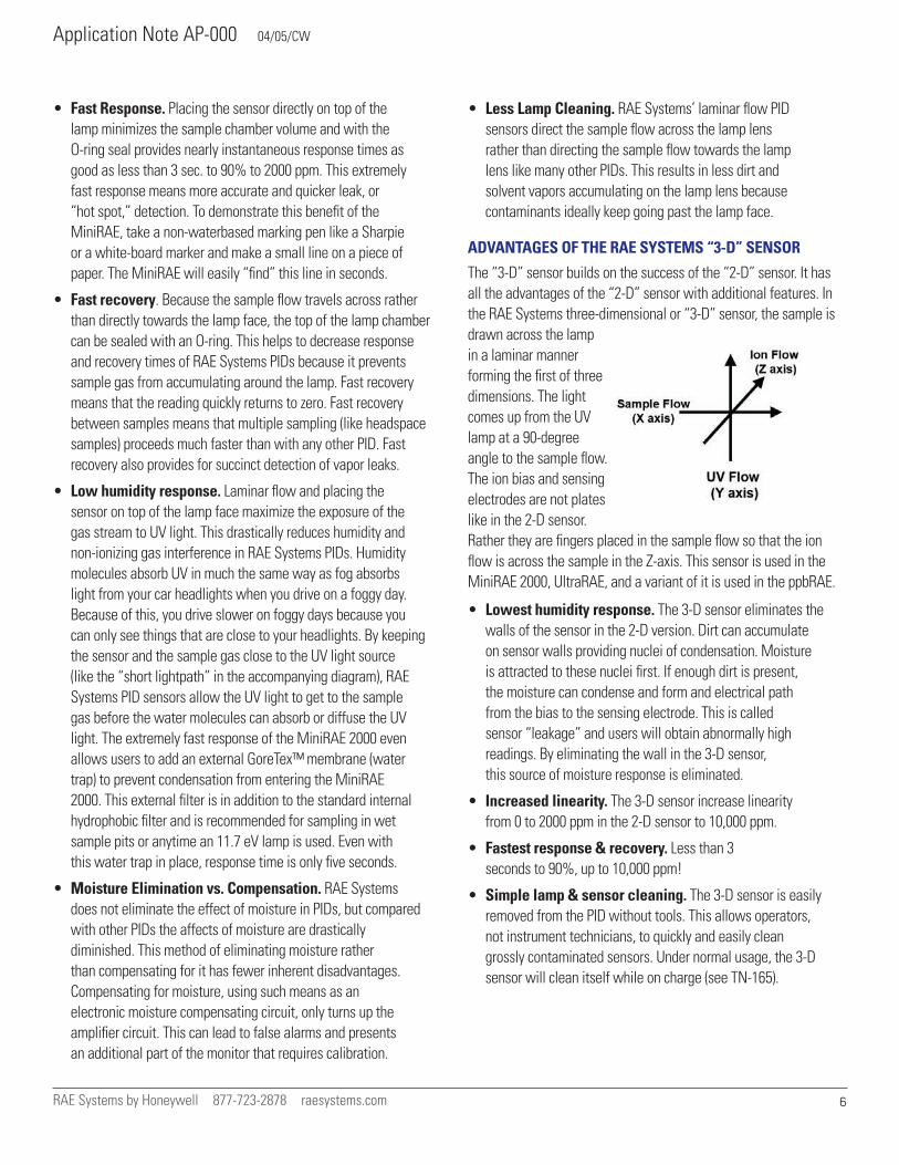
ADVANTAGES OF THE RAE SYSTEMS “3-D” SENSOR
The “3-D” sensor builds on the success of the “2-D” sensor. It has all the advantages of the “2-D” sensor with additional features. In the RAE Systems three-dimensional or “3-D” sensor, the sample is drawn across the lamp in a laminar manner forming the first of three dimensions. The light comes up from the UV lamp at a 90-degree angle to the sample flow. The ion bias and sensing electrodes are not plates like in the 2-D sensor. Rather they are fingers placed in the sample flow so that the ion flow is across the sample in the Z-axis. This sensor is used in the MiniRAE 2000, UltraRAE, and a variant of it is used in the ppbRAE.
• Lowest humidity response. The 3-D sensor eliminates the walls of the sensor in the 2-D version. Dirt can accumulate on sensor walls providing nuclei of condensation. Moisture is attracted to these nuclei first. If enough dirt is present, the moisture can condense and form and electrical path from the bias to the sensing electrode. This is called sensor “leakage” and users will obtain abnormally high readings. By eliminating the wall in the 3-D sensor, this source of moisture response is eliminated.
• Increased linearity. The 3-D sensor increase linearity from 0 to 2000 ppm in the 2-D sensor to 10,000 ppm.
• Fastest response & recovery. Less than 3 seconds to 90%, up to 10,000 ppm!
• Simple lamp & sensor cleaning. The 3-D sensor is easily removed from the PID without tools. This allows operators, not instrument technicians, to quickly and easily clean grossly contaminated sensors. Under normal usage, the 3-D sensor will clean itself while on charge (see TN-165).
Application Note AP-000 04/05/CW
RAE Systems by Honeywell 877-723-2878 raesystems.com 7
TIPS ON USING A PID
Never Use Tygon Sample Tubing
Because Tygon sample tubing quickly absorbs many chemical vapors, it should never be used with PIDs. Tygon tubing will reduce the PID readout when measuring many chemicals and may cause “false positives” when chemicals do not exist due to the “outgasing” of old chemicals from theTygon tubing. Tygon tubing is typically found as the remote sampling tubing supplied with most confined space monitors. Only Teflon, Teflon-lined tygon or similar non-reactive tubing should be used with PIDs. Teflon tubing will not absorb chemicals, but it can get coated. Clean contaminated Teflon tubing with anhydrous methanol (lamp-cleaning solution) if it gets coated with a chemical.
When to Clean a PID
From time to time, a PID lamp and sensor requires cleaning. Historically, some PID users cleaned their lamps daily, often neglecting the sensor and sample components before the sensor. Frequent cleaning typically is not necessary and can lead to inadvertent damage to the PID lamp and sensor. The following are guidelines for determining when a PID lamp and sensor require cleaning:
• When display creeps upwards after good zero.
• When PID responds to moisture.
• When movement of PID results in response on display. How to Clean the PID Lamp & Sensor
1. Use anhydrous methanol (lamp-cleaning solution).
2. Clean sample probe and replace or clean filters. If the PID holds a stable zero after this step, then further cleaning may not be necessary.
3. Clean the lamp face with lens tissue
4. Clean the sensor by immersion in cleaning solution (an ultrasonic cleaner will speed cleaning).
Drying the PID
1. Let the cleaned PID air dry overnight.
2. Warm air (not hot) speeds drying.
REFERENCES
Carol J. Maslansky, Steven P. Maslansky: Photoionization Detectors in Air Monitoring Instrumentation, Van Nostrand Reinhold, New York, 1993
NIOSH: Pocket Guide to Chemical Hazards, NIOSH Publications, Cincinnati, OH, 1994
RAE Systems: Correction Factors and Ionization Potentials (Technical Note TN-106)
RAE Systems: Setting Alarm Limits for Mixtures (Technical Note TN-130)
RAE Systems: Measuring Correcton Factors for Volatile Compounds with PIDs (TN-120) PID Training Outline