Embed Size (px)
Citation preview

1
Application Note 21 L2TP over IPSEC VPN server
Digi Technical Support
June 2016

2
Contents
1 Introduction .......................................................................................................................................... 3
1.1 Outline .......................................................................................................................................... 3
1.2 Assumptions ................................................................................................................................. 3
1.3 Corrections .................................................................................................................................. 4
1.4 Version ......................................................................................................................................... 4
2 Configuration .......................................................................................................................................5
2.1 Cellular WAN Configuration ..........................................................................................................5
2.2 LAN Configuration ........................................................................................................................5
2.3 IPsec Tunnel Configuration ........................................................................................................... 7
2.4 Configure the TransPort L2TP settings for multiple sessions ...................................................... 14
2.5 Configure the TransPort PPP Settings ........................................................................................ 15
2.6 Server GUI Access, Preshared Key and Remote Users Configuration .......................................... 19
2.7 L2TP Server behind NAT Windows Configuration ...................................................................... 22
2.8 Configure VPN Connection on Vista/Windows 7, running L2TP Client........................................ 22
2.9 Configure VPN Connection on Windows 8 running L2TP Client ................................................. 28
2.10 Configure VPN Connection on Windows XP running L2TP Client ................................................ 31
2.11 Windows 2000/XP Additional Settings ........................................................................................ 35
2.12 Manually specifying a Windows client IP address ........................................................................ 36
3 Testing ............................................................................................................................................... 37
3.1 Connect Remote Clients to the L2TP Server ............................................................................... 37
3.2 Confirm Traffic Traverses the L2TP Tunnels .............................................................................. 40
4 Troubleshooting ................................................................................................................................ 46
4.1 Error 789 on the Windows PC client: .......................................................................................... 46
4.2 Error 682 on the Windows PC client: .......................................................................................... 46
5 Configuration Files............................................................................................................................. 48
5.1 TransPort configuration file ....................................................................................................... 48
5.2 TransPort firmware version .........................................................................................................56

3
1 INTRODUCTION
1.1 Outline
Layer 2 Tunneling Protocol (L2TP) can be used to tunnel layer 2 frames and thus provide remote access to
a private LAN.
IPsec is a standard for encryption and security; running L2TP over IPSEC can therefore provide secure
encrypted remote access to a private LAN. This is commonly known as a VPN or Virtual Private Network
connection.
Microsoft Windows XP TM and Vista TM/ Windows 7 TM provide a VPN client that is capable of running L2TP
over IPsec. This Application Note (AN) explains the procedure of configuring a TransPort to act as an
L2TP/IPsec VPN server for a Windows XP TM, Vista TM or Windows 7 TM client.
This solution works even if the client does not have a public IP address, i.e. is connecting from a behind a
router running NAT.
Multiple remote hosts will open a VPN tunnel between themselves and the VPN server. L2TP will run over
the IPsec connection and the PPP connection will be negotiated over the newly established L2TP pipe.
The remote PCs will be running the Microsoft® Windows™ L2TP over IPsec VPN Client with a Dial-up
Networking connection to an ISP. This AN will also take the user through the Microsoft® Windows™
Connection Wizard.
NOTE: Although in this example the WR44v2 model is used, the same settings can be applied to all other
TransPort models (certain models may need the IPsec encryption software option to be enabled).
1.2 Assumptions
This guide has been written for use by technically competent personnel with a good understanding of the
communications technologies used in the product, and of the requirements for their specific application.

4
This AN applies to:
Models shown: TransPort WR44v2.
Other Compatible Models: All Digi TransPort products.
Firmware versions: 5.123 or later.
NOTE: This AN has been specifically rewritten for firmware release 5.123 and later but the original
AN was testing and working for routers running earlier firmware and the previous GUI. Routers
running earlier firmware will find that the screen shots do not accurately reflect what will be seen
on those older routers. Contact [email protected] if you require this document for the older
GUI.
Configuration: This AN assumes the devices are set to their factory default configurations. Most
configuration commands are only shown if they differ from the factory default.
Users have access to the TransPort command line interface (via serial port or telnet) and also the web
interface.
This AN applies only to:
TransPorts running the specified firmware version above (or newer) and factory default settings.
Client OS: Microsoft® XP™ SP1 or SP2 with correct registry settings (see Additional Assumptions)
or Windows Vista/Windows 7, default settings.
Client VPN: Microsoft® Windows™ L2TP IPsec VPN
Internet Connection:
PC is connected to an ISP that allows PPP dialup and allocates a public or “NAT’ed” (via Network Address
Translation) IP addresses with Internet access.
1.3 Corrections
Requests for corrections or amendments to this Application Note are welcome and should be addressed
Requests for new ANs can be sent to the same address.
1.4 Version
Status
1.0 Published
1.1 Corrections and enhancement
1.2 Now supports server behind NAT
1.3 Now supports Vista
1.4 Added new section on using static IPs
2.0 New Gui version 5.123 onwards
2.1 Updated screenshots and instructions for new web interface, rebranding (Jun 2016)

5
2 CONFIGURATION
2.1 Cellular WAN Configuration
The TransPort will act as the VPN server and will need to be connected to the public Internet to allow
clients to establish an IPsec and finally an L2TP connection. This can be any interface; this AN will assume
PPP 1 for cellular, but ADSL, Ethernet, ISDN, etc. are just as acceptable.
Enable IPsec on the WAN interface and then click the Apply button.
2.2 LAN Configuration
Now assign an IP address and subnet mask to the Ethernet port. This is for the private LAN that the
remote client requires access to. The settings shown in italics are user dependent.
CONFIGURATION > NETWORK > INTERFACES > ETHERNET > ETH 0
Using the TransPort’s web interface, navigate to the above link and use this form to enter Ethernet 0
settings:
Parameter Setting Description
Description <Description of
Interface> Use something here that will be meaningful
to your setup, e.g. “AN21 Test LAN”
IP Address <LAN_IP_Address> Ethernet 0 IP address
Mask <Subnet_Mask> Ethernet 0 subnet mask

6
Command line commands to achieve the above:
eth 0 descr "AN21 Test LAN" eth 0 IPaddr "192.168.63.194"
2.2.1 Local LAN DHCP Configuration
If you do not intend to use DHCP on the local LAN, then the settings here can be cleared. If using DHCP for
the local LAN clients, then as the default LAN IP address range has been changed, the matching Eth 0
DHCP settings need to be changed too.
CONFIGURATION - NETWORK > DHCP SERVER > DHCP SERVER FOR ETHERNET 0
Using the TransPort web interface, navigate to the above path and use the form just below to enter Eth 0
DHCP settings, and then click the ‘Apply’ button:
Parameter Setting Description
IP Addresses 192.168.63.195 The first free IP address in the range you wish
to allocate to DHCP users
to 192.168.63.214 The last free IP address in the range you wish
to allocate to DHCP users
Mask 255.255.255.0 Ethernet 0 subnet mask
Gateway 192.168.63.194 Eth 0 IP Address
DNS Server 192.168.63.194 Eth 0 IP Address or address of the network
DNS server

7
Command line commands to achieve the above:
dhcp 0 IPmin "192.168.63.195" dhcp 0 respdelms 500 dhcp 0 mask "255.255.255.0" dhcp 0 gateway "192.168.63.194" dhcp 0 DNS "192.168.63.194"
2.3 IPsec Tunnel Configuration
In this example, L2TP will connect across an established IPsec VPN tunnel, so first an IPsec Security
Association (SA) with an initiating peer will need to be established. This section contains the configuration
for all the initiating IPsec peers.

8
CONFIGURATION > NETWORK > VIRTUAL PRIVATE NETWORKING (VPN) > IPSEC > IPSEC
TUNNELS > IPSEC 0
Using the TransPort web interface, navigate to the above path and use this form to enter IPsec settings:
Parameter Setting Description
Description <Description of
Interface> Use something meaningful to your setup, e.g.
“L2Tp Eroute Vista and Win 7”
Use interface PPP Select PPP from the drop down box for the
Local LAN interface address
Use interface 1 Enter the instance number in the second box
for the Local LAN interface address
Use the following security on this
tunnel Preshared Keys
Select the radio button for the required option
Remote ID * This will allow any ID to build a tunnel
Use <ENC> encryption on this
tunnel AES (128 bit keys)
Select the encryption type used for this tunnel
Use <AUTH> authentication on
this tunnel SHA1
Select the authentication method to be used on this tunnel
Renew the tunnel after
1 hrs 0 mins 0 secs
Set the period of time for SA to stay valid on this tunnel before rekey
Renew the tunnel after ... of traffic
250 Mbytes Enter 250 in the first box and select Mbytes in
the second box

9
Expand the Advanced section, enter these additional values, and then click the ‘Apply’ button:
Parameter Setting Description
IPsec mode Transport Select the relevant radio button to change the tunnel from Tunnel mode to Transport
mode
Allow <PROT> IP protocol(s) in this
tunnel UDP
L2TP traffic is UDP only so we restrict the tunnel to only carry this traffic
Remote TCP/UDP port
1701 L2TP traffic only uses port 1701 so we restrict
to this port only

10
** If 3DES/AES is not available as an option, the TransPort needs the “Encryption software” option.
*** SHA1 is used by Windows Vista & Windows 7. If the client computer is Windows XP, set this to “MD5”.
If both XP and Vista machines are used, two eroutes will be needed please see next section.
Command line commands to achieve the above:
eroute 0 descr "L2TP Eroute Vista and Win 7" eroute 0 peerid "*" eroute 0 locipifent "PPP" eroute 0 locipifadd 1 eroute 0 mode "Transport" eroute 0 ESPauth "SHA1" eroute 0 ESPenc "AES" eroute 0 proto "UDP" eroute 0 remport 1701 eroute 0 ltime 3600 eroute 0 lkbytes 250000 eroute 0 authmeth "PRESHARED" eroute 0 enckeybits 128

11
2.3.1 Optional IPsec (Windows XP) Tunnel Configuration
To enable this configuration to work with Windows XP, a second eroute must be configured. This is
because Vista is set by default to a higher encryption standard that is not supported by Windows XP.
CONFIGURATION > NETWORK > VIRTUAL PRIVATE NETWORKING (VPN) > IPSEC > IPSEC TUNNELS
> IPSEC 1
Using the TransPort’s web interface, navigate to the above link and use this form to enter IPsec settings:
Parameter Setting Description
Description <Description of
Interface> Use something meaningful to your setup, e.g.
“L2Tp Eroute XP”
Use interface PPP Select PPP from the drop down box for the
local LAN interface address
Use interface 1 Enter the instance number in the second box
for the local LAN interface address
Use the following security on this
tunnel Preshared Keys
Select the radio button for the required option
Remote ID * This will allow any ID to build a tunnel
Use <ENC> encryption on this
tunnel 3DES
Select the encryption type used for this tunnel
Use <AUTH> authentication on
this tunnel MD5
Select the authentication method to be used on this tunnel
Renew the tunnel after
1 hrs 0 mins 0 secs
Set the period of time for SA to stay valid on this tunnel before rekey
Renew the tunnel after ... of traffic
250 Mbytes Enter 250 in the first box and select Mbytes in
the second box

12
Expand the Advanced section, enter these additional values, and then click the ‘Apply’ button:
Parameter Setting Description
IPsec mode Transport Select the relevant radio button to change the tunnel from Tunnel mode to TransPort
mode
Allow <PROT> IP protocol(s) on this
tunnel UDP
L2TP traffic is UDP only so we restrict the tunnel to only carry this traffic
Destination TCP/UDP port
1701 L2TP traffic only uses port 1701 so we restrict
to this port only

13
NOTE: The only differences between this tunnel and the previous one are the ESP Encapsulation method
and Auth Algorithm.
Command line commands to achieve the above:
eroute 1 descr "L2TP Eroute XP" eroute 1 peerid "*" eroute 1 locipifent "PPP" eroute 1 locipifadd 1 eroute 1 mode "Transport" eroute 1 ESPauth "MD5" eroute 1 ESPenc "3DES" eroute 1 proto "UDP" eroute 1 remport 1701 eroute 1 ltime 3600 eroute 1 lkbytes 250000 eroute 1 authmeth "PRESHARED"

14
2.4 Configure the TransPort L2TP settings for multiple sessions
L2TP will provide a tunnel through which a logical PPP connection can be established. When the TransPort
is configured to be an L2TP Server, it listens on UDP port 1701 and terminates L2TP connections. It then
only allows PPP frames to be passed in the L2TP “tunnel” between the TransPort and the PC. As there is a
need for multiple L2TP sessions, multiple L2TP instances will need to be created. In this AN, ten L2TP
instances (0-9) will be configured.
CONFIGURATION - NETWORK > VIRTUAL PRIVATE NETWORKING (VPN) > L2TP > L2TP 0
Using the TransPort web interface, navigate to the above link to enter the L2TP settings, and then
continue configuring the nine remaining L2TP instances from 1-9.
Parameter Setting Description
Act as a listener only
Ticked Sets L2TP 0 to Listen on UDP port 1701
(L2TP)
Enable Server mode
Ticked Sets L2TP 0 to be an L2TP Server, not
initiator
Command line commands to achieve the above:
l2tp 0 listen ON l2tp 0 swap_io ON
Command line commands to complete the setup for the other 9 L2TP instances:
l2tp 1 listen ON l2tp 1 swap_io ON l2tp 2 listen ON l2tp 2 swap_io ON l2tp 3 listen ON l2tp 3 swap_io ON

15
l2tp 4 listen ON l2tp 4 swap_io ON l2tp 5 listen ON l2tp 5 swap_io ON l2tp 6 listen ON l2tp 6 swap_io ON l2tp 7 listen ON l2tp 7 swap_io ON l2tp 8 listen ON l2tp 8 swap_io ON l2tp 9 listen ON l2tp 9 swap_io ON
2.5 Configure the TransPort PPP Settings
PPP frames passed up from the L2TP layer will be terminated by a PPP instance. Again, as there is a need
for multiple PPP sessions, multiple PPP instances will need to be configured. In this AN, PPP instances 10-
19 will be configured.
CONFIGURATION - NETWORK > INTERFACES > ADVANCED > PPP 10 - 19 > PPP 10
Using the TransPort web interface, navigate to path above and then click the ‘Load answering defaults’
button:
Once the answering defaults have been loaded, which can be confirmed by looking for the “Answering
config loaded” message to the right of the buttons, enter the L2TP configuration detailed below:
Parameter Setting Description
Description <Description of
Interface> Use something meaningful to your setup, e.g.
“L2TP 0 Dial in Interface”
This PPP interface will use
L2TP Select from the drop down menu
This PPP interface will use
0 Enter L2TP instance into the right hand box
Use <IPADDRESS> as the local IP
address for this router
<ETH_0_IP_Address> The address that this PPP interface will use
Attempt to assign the following IP configuration to remote devices
Ticked Enable remote dialup user IP assignment
Assign remote IP addresses from
<IP_Address1> to <IP_Address2>
*<IP_Address> Both values will be the same address in this
project – choose a free address in your IP addressing schema
Allow this PPP interface to answer
incoming calls Ticked
When enabled, causes the PPP instance to answer an incoming call

16
Close PPP connection ... if it has been idle for
0 hrs 0 mins 0 secs
Remove any values in these boxes so the connection never times out

17
The windows client will use 1400 for the MRU on this link, so we need to match this on our end. Expand
the ‘PPP Negotiation’ section, enter the following settings, and then click the ‘Apply’ button:
Parameter Setting Description
Desired local MRU 1400 Set the local MRU for the connection
Desired remote MRU
1400 Set the remote MRU for the connection
The settings shown in italics are user dependent.
NOTE #1: The “Assign remote IP addresses from <IP_Address1> to <IP_Address2>” setting specifies the
IP address that will be assigned to the remote client for each PPP instance (see Note #2 just below). This
should therefore be different for each PPP instance that you configure. In this example, an IP address on
the same subnet as the private LAN has been chosen. You must ensure that no other hosts on the private
LAN use this address. It is possible to assign an address to the remote clients that are in a different subnet
to that of the private LAN. However, if you choose to do this, any hosts on the private LAN will need to use
the TransPort as the gateway for this subnet.
If you do choose to assign an IP address to the remote client that is on the same subnet as the TransPort
local LAN, then you can choose whether broadcast packets should be routed to the remote unit by setting
the advanced PPP parameter “Forward IP broadcasts over this interface if this interface is on the same IP
network as an Ethernet interface” as appropriate (ticked for on, unticked for off). The default and
recommended value is NOT to forward broadcasts.
The advantage of forwarding broadcasts is that software features that make use of broadcast packets
(such as browsing for work groups and PCs through the “Entire Network” in Windows Explorer) should
work. The disadvantage is that an excessively large amount of traffic could be sent over the VPN tunnel
thus rendering it expensive and/or slow.
NOTE #2: This address can (not must) be an address in the LAN subnet. The address must not be in used
by another device on the same subnet as the TransPort LAN. If an address on the LAN subnet is chosen,
the TransPort will use proxy ARP and so no routing changes will be required to any devices on the LAN.
A user can be associated with a static address for their username and this is done by allocating an IP under
the user setup for access in the next section.
The Windows VPN properties can be configured to manually specify the IP address that
when connecting in to the TransPort. For example, if there are multiple answering PPP
multiple PCs connecting in and each PC must use a specific IP address, rather than the
pool, the TransPort is configured with on each PPP instance. If this is required, see the
section titled “

18
Manually specifying a Windows client IP address”.
Each answering PPP instance needs to be associated with a different answering L2TP instance.
The suggested Layer 1 interface settings for this AN are:
PPP 19 L2TP instance 9
PPP 18 L2TP instance 8
PPP 17 L2TP instance 7
PPP 16 L2TP instance 6
PPP 15 L2TP instance 5
PPP 14 L2TP instance 4
PPP 13 L2TP instance 3
PPP 12 L2TP instance 2
PPP 11 L2TP instance 1
PPP 10 L2TP instance 0
Command line commands to achieve the above:
ppp 10 name "L2TP 0 Dial in Interface" ppp 10 l1iface "L2TP" ppp 10 r_addr ON ppp 10 IPaddr "192.168.63.194" ppp 10 mask "255.255.255.255" ppp 10 DNSport 53 ppp 10 IPmin "192.168.63.100" ppp 10 IPrange 1 ppp 10 ans ON ppp 10 metric 1 ppp 10 netip "0.0.0.0" ppp 10 ip2count 3 ppp 10 ripauth 1 ppp 10 inrip ON ppp 10 maxneg 80 ppp 10 l_accm "0x00000000" ppp 10 r_accm "0xffffffff" ppp 10 l_mru 1400 ppp 10 r_mru 1400 ppp 10 l_acfc ON ppp 10 l_pap ON ppp 10 l_chap ON ppp 10 l_comp ON ppp 10 l_pfc ON ppp 10 r_callb 1 ppp 10 l_md5 1 ppp 10 r_md5 ON ppp 10 r_ms1 ON ppp 10 r_ms2 ON ppp 10 lcn 1027 ppp 10 defpak 128 ppp 10 baklcn 1027

19
Command line commands to complete the setup for the other nine PPP for L2TP Dial in interfaces (11-19)
can be found in Section 5.1.
2.6 Server GUI Access, Preshared Key and Remote Users Configuration
2.6.1 Administration User Setup
CONFIGURATION - SECURITY > USERS > USER 0 - 9 > USER 1
As this project involves configuring a unit to be on a public address, it is highly recommended that you use
the firewall and change the default username and password. Navigate to the path above and change the
following values:
Parameter Setting Description
Username <Admin_User_Name> It is recommended that you change this to
something unique
Password <Admin_User_Password> It is recommended that you change this to
something unique and hard to guess
Confirm Password <Admin_User_Password> Confirm the password in the section above
2.6.2 Preshared Key Setup
CONFIGURATION - SECURITY > USERS > USER 10 - 14 > USER 14
The last user instance will need to be configured with the IPsec preshared key. Navigate to the last user
instance (choose the last one if there are more than 14) to enter and confirm the preshared key, then
expand the ‘Advanced’ section and untick the ‘Allow this user to log in over a PPP network’ option:
Parameter Setting Description
Username * Wild card to allow any remote VPN client
access
Password <shared_secret_key> Pre-Shared Key remote VPN Client will use
Confirm Password <shared_secret_key> Pre-Shared Key remote VPN Client will use
Access Level None Users knowing this password will not be
allowed to log on to administer the TransPort

20
Allow this user to log in over a PPP
network Unticked
This will prevent users gaining access to the network with any username and the
preshared key as the password
Command line commands to achieve the above:
user 14 name "*" user 14 password "shared_secret_key" user 14 access 4 user 14 dun_en OFF
2.6.3 Remote User Configuration
CONFIGURATION - SECURITY > USERS > USER 0 – 9 > USER 9
Good network security practice would dictate that you will need to setup at least one user for each remote
access L2TP user instance available. You may then remove access to an individual without having to get
all other users to change their settings (please note that the TransPort can support RADIUS or TACACS+
for remote user authentication). In this project, we are setting up seven instances so the seven users 3
through 9 can be configured:

21
You can assign remote users for general access for the L2TP tunnels to users 3 through 9.
NOTE: This password field represents the password that the end user will input into the Windows PC
client, which should be different than the password for the “*” user, which is the preshared key.
2.6.4 Remote User with Static IP Assignment
CONFIGURATION - SECURITY > USERS > USER 0 - 9> USER 2
A remote user can be allocated a static remote IP addresses so that they always have the same IP when
they connect. This assignment overrides the PPP configured IP assigned in the configuration step above
upon connection. We set the user so that they have no CLI or GUI access by setting the Access Level to
‘None’; this doesn’t affect whether the user can access the L2TP tunnel. In the following configuration, the
remote user will receive the IP allocation 192.168.63.10. This user will be used to access the project in the
testing section in Section 3.

22
NOTE: This password field represents the password that the end user will input into the Windows PC
client, which should be different than the password for the “*” user, which is the preshared key.
2.7 L2TP Server behind NAT Windows Configuration
In the special case of the TransPort L2TP/IPsec Server being behind NAT, it is necessary to create the
following case sensitive DWORD registry key and set the value to “2”.
HKEY_LOCAL_MACHINE\SYSTEM\CurrentControlSet\Services\IPsec\AssumeUDPEncapsulationCont
extOnSendRule
http://support.microsoft.com/kb/885407/
2.8 Configure VPN Connection on Vista/Windows 7, running L2TP Client
L2TP will run over an IPsec connection between the PC and the TransPort. This in turn will run over the
PC’s existing ISP connection. As there is a need for multiple L2TP sessions, from multiple remote PCs, this
procedure will need to be replicated on as many remote PCs as needed.
Open Control Panel -> Network and Sharing Center:

23
Within it Select Set up a connection or network. This will bring up the Set Up a Connection or Network
wizard:
Select Connect to a workplace:

24
If prompted to use an existing connection or not, select No, create a new connection and click Next:
Select Use my Internet connection (VPN):

25
Type the Internet address of the TransPort in the Internet Address box. The Destination Name labels the
connection for your use - it does not affect how the VPN works. The only other thing to tick is “Don’t
connect now, just set it up so I can connect later”. Make sure the others are unticked.
Hit Next:
Put the appropriate Username and Password in and optionally select Remember this password.

26
NOTE: This password field represents the password specific to the username in question. This password is
different than the preshared key (the password for the * user).
Click Create:
Click Close, open the Properties of the new network connection and select the Security tab:

27
Set Type of VPN to Layer 2 Tunneling Protocol with IPsec (L2TP/IPsec).
Click the Advanced Settings button:
Select Use preshared key for authentication and input the shared key in the Key field. The Preshared key
is the password of the “*” user that was setup earlier on the TransPort.
Click OK then click OK again to save the settings.
Double-click on the connection to activate it. If the password was not saved in the earlier step, it will need
to be re-entered.

28
2.9 Configure VPN Connection on Windows 8 running L2TP Client
L2TP will run over an IPsec connection between the PC and the TransPort; this in turn will run over the PC’s
existing ISP connection. As there is a need for multiple L2TP sessions, from multiple remote PCs, this
procedure will need to be replicated on as many remote PCs as needed.
Open Control Panel -> Network and Sharing Center. Within it, select Set up a connection or network.
This will bring up the Set Up a Connection or Network wizard:
Select Connect to a Workplace:

29
Select Use my Internet connection (VPN):
Type the Internet address of the TransPort in the Internet Address box. The Destination name labels the
connection for your use. It does not affect how the VPN works.
Hit Create. The new connection will appear on the sidebar. Do not hit Connect now.

30
Right-click on the VPN Connection and chose View Connection Properties. Select the Security tab, set
the Type of VPN to L2TP IPsec VPN, and then click the Advanced Settings button.
Select Use preshared key for authentication, put the shared key in the Key text box, click OK, and then
click OK again to save the settings.

31
You can then go back to the side bar, select the connection, click Connect and enter the username and
password:
2.10 Configure VPN Connection on Windows XP running L2TP Client
L2TP will run over an IPsec connection between the PC and the TransPort. This in turn will run over the
PC’s existing ISP connection. As there is a need for multiple L2TP sessions, from multiple remote
PC’s, this procedure will need to be replicated on as many remote PCs as needed.
Note: The following configuration is for Windows XP. Windows Vista is very similar.
From the ‘Start’ Menu navigate to Settings Network Connections Create New Connection to open
the New Connection wizard.

32
Click Next, select Connect to the network at my workplace from the list, and then click Next
again.
Select Virtual Private Network connection from the list and click Next. Now give the VPN
connection a name .i.e. “L2TP Connection” and click Next.

33
Now add the Public IP address given to the TransPort WAN interface to the ‘Host name of Domain
name’ field and click Next, then finally click Finish.

34
Now some additional settings have to be changed to allow the VPN connection to use IPsec to reach the
TransPort. Click on Properties and then the Security tab, now select IPsec settings, tick the ‘Use pre-
shared key for authentication’ option and add in the Pre_shared_key defined in 2.6.2, now the click OK
once again.

35
Select the Networking tab, from the list under Type of VPN select ‘L2TP IPsec VPN’ and click OK.
To activate the connection, put the appropriate Username and Password in, optionally select Remember
this password, and then click the Connect button.
NOTE: This password field represents the password specific to the username in question. This password is
different than the preshared key (the password for the * user).
2.11 Windows 2000/XP Additional Settings
The ProhibitIpSec registry value if present must NOT be set to 1 in any Windows 2000-based endpoint
computer of a L2TP/IPsec connection. This registry value prevents the automatic filter for L2TP/IPsec
traffic from being created. When the ProhibitIpSec registry value is set to 1, your Windows 2000/XP
computer does not create the IPSEC connection before initiating the L2TP tunnel.
To check the ProhibitIpSec registry value, follow these steps:
1. Start Registry Editor.
2. Locate and then click the following registry subkey:
HKEY_LOCAL_MACHINE\System\CurrentControlSet\Services\Rasman\Parameters
3. Check if the prohibitipsec value exists.
4. If it exists either delete the key or ensure it is set to 0 and not 1.
5. Quit Registry Editor, and then restart the computer.
Warning If you use Registry Editor incorrectly, you may cause serious problems that may
require you to reinstall your Operating System. Use the Registry Editor at your own risk.
36
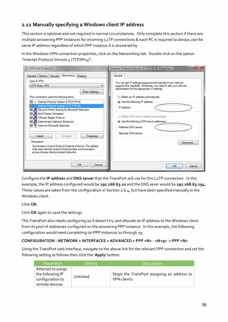
2.12 Manually specifying a Windows client IP address
This section is optional and not required in normal circumstances. Only complete this section if there are
multiple answering PPP instances for incoming L2TP connections & each PC is required to always use the
same IP address regardless of which PPP instance it is answered by.
In the Windows VPN connection properties, click on the Networking tab. Double click on the option
“Internet Protocol Version 4 (TCP/IPv4)”.
Configure the IP address and DNS server that the TransPort will use for this L2TP connection. In this
example, the IP address configured would be 192.168.63.10 and the DNS sever would be 192.168.63.194.
These values are taken from the configuration in Section 2.6.4, but have been specified manually in the
Windows client.
Click OK.
Click OK again to save the settings.
The TransPort also needs configuring so it doesn’t try and allocate an IP address to the Windows client
from its pool of addresses configured on the answering PPP instance. In this example, the following
configuration would need completing on PPP instances 10 through 19.
CONFIGURATION - NETWORK > INTERFACES > ADVANCED > PPP <N> - <N+9> > PPP <N>
Using the TransPort web interface, navigate to the above link for the relevant PPP connection and set the
following setting as follows then click the ‘Apply’ button:
Parameter Setting Description
Attempt to assign the following IP configuration to remote devices
Unticked Stops the TransPort assigning an address to VPN clients

37
Command line commands to achieve the above, using PPP instance 10 as an example:
ppp 10 IPmin ! ppp 10 IPrange !
3 TESTING
3.1 Connect Remote Clients to the L2TP Server
This test stage will show that the IPsec/L2TP tunnel has been established.
Windows XP – Click Start > Connect To > L2TP Connection (the name will depend on what name you gave
the connection when you set this up). Enter the username and password and then click the ‘Connect’
button.
Windows 7 – Click the network icon, click the connection from the list then click the ‘Connect’ button.
Enter the username and password, and then click ‘Connect’ again.

38
When the PC tries to establish a L2TP tunnel to the VPN Server an IPsec Security Association is established
first. This allows the L2TP packets to be encrypted with in the IPsec Tunnel.
MANAGEMENT - EVENT LOG
On the VPN Server’s web interface, navigate to the above link and click on the ‘Clear Log’ button:
Connect the PC to the Internet using an ISP that allows PPP dialup and allocates a Public IP addresses.
Now click ‘Connect’ on the L2TP/VPN connection created earlier. After some brief negotiations, the PC’s
VPN client shall receive an IP address, via PPP, from the VPN Server.
Re-navigate to the Event Log. Each stage of the L2TP establishment will have been entered in the Event
Log.
Highest PPP instance answers packets passed up from L2TP layer 17:37:27, 14 Jun 2011,PPP 19 up 17:37:27, 14 Jun 2011,PPP 19 Start IPCP 17:37:27, 14 Jun 2011,PPP Login OK by Remote_User_Static_1 lvl 4 17:37:27, 14 Jun 2011,PPP 19 Start AUTHENTICATE 17:37:27, 14 Jun 2011,PPP 19 Start LCP 17:37:27, 14 Jun 2011,PPP 19 Start L2TP Answering L2TP packets encrypted in IPSec tunnel 17:37:27, 14 Jun 2011,L2TP Call 9 up 17:37:27, 14 Jun 2011,L2TP Tunnel 0 up IPSec SA up 17:37:27, 14 Jun 2011,(2) IKE SA Removed. Peer: 10.1.63.1,Successful Negotiation 17:37:27, 14 Jun 2011,Eroute 0 VPN up peer: 10.1.63.1 17:37:27, 14 Jun 2011,New IPSec SA created by 10.1.63.1

39
17:37:27, 14 Jun 2011,(2) New Phase 2 IKE Session 79.75.71.39,Responder IKE SA up 17:37:26, 14 Jun 2011,(1) IKE Keys Negotiated. Peer: 17:37:26, 14 Jun 2011,(1) New Phase 1 IKE Session 79.75.71.39,Responder
MANAGEMENT - CONNECTIONS > VIRTUAL PRIVATE NETWORKING (VPN) > IPSEC > IPSEC
TUNNELS > IPSEC TUNNELS 0 - 9 > IPSEC TUNNELS 0 - 9
Navigate to the above link where the status of the newly established IPsec tunnels can be seen. The first
column shows which tunnel number the tunnel is connected to. In this example, two machines are
connected, an XP and a Windows 7.
The TransPort is designed to allow the highest numbered PPP instance to answer an incoming PPP call. If
two devices are connected then they will be connected to the two highest numbered PPP instances (in this
example PPP 19 and PPP 18). For PPP 19 connection, navigate to the link below. This page will show the
local IP address that the PPP instance is using (please note this is not the IP of the remote device, but the
local interface address on the TransPort) and the L2TP instance that is associated with this PPP call.
MANAGEMENT - NETWORK STATUS > INTERFACES > ADVANCED > PPP > PPP 10 - 19 > PPP 19
MANAGEMENT - NETWORK STATUS > INTERFACES > ADVANCED > PPP > PPP 10 - 19 > PPP 18
The link above will show the other connected interface as below.

40
The PC client will now have an L2TP tunnel running PPP on to the VPN Server.
3.2 Confirm Traffic Traverses the L2TP Tunnels
This test stage will show traffic passing across the tunnel to hosts on the LAN side of the VPN server. In
this scenario, an ICMP Echo Request/Reply (or PING) will pass from the PC to a server on the LAN side of
the TransPort.
MANAGEMENT > ANALYSER > SETTINGS
Set the Analyser to show ICMP traffic. Navigate to the above link and set the following settings then click
the ‘Apply’ button:
Parameter Setting Description
Enable Analyser Ticked Enable analysis of network events
Maximum packet capture size
128 Bytes to be collected on the interfaces
Log size 180 Set the analyser to the maximum size
Enable IKE debug Unticked Disable logging of Tunnel negotiations
Clear all Serial Interfaces
Click Click to clear any asy port monitoring
Clear all Ethernet Interfaces
Click Click to clear any Ethernet interface monitoring
Clear all PPP Interfaces
Click Click to clear any PPP interface monitoring
PPP Interfaces ETH 0 PPP 18 PPP 19
Select only these three interfaces
Trace discarded packets
Ticked Track discarded packets
Ethernet Packet Filters
Clear Remove any settings in this section
IP Packet Filters:TCP/UDP Ports:
Clear Remove any settings in this section
IP Packet Filters:IP Protocols
~1 We are monitoring ICMP only
IP Packet Filters: IP Addresses
Clear Remove any settings in this section
Discarded IP Clear Remove any settings in this section

41
Packet Filters: TCP/UDP Ports:
Discarded IP Packet Filters:IP Protocols
~1 We are monitoring ICMP only
Discarded IP Packet Filters: IP Addresses
Clear Remove any settings in this section

42
MANAGEMENT - ANALYSER > TRACE
Click on ‘Trace’ and click ‘Clear Trace’:
Open the Windows 7 PC’s command (DOS) window. At the prompt type:
ping 192.168.63.1 –n 1
Press Enter then type:
ipconfig
Press Enter to view the allocated IP (in this instance this is 192.168.63.10 as the statically assigned IP for
the Remote_User_Static) on the L2TP connection. As you can see below, the remote client has been
issued with the Static IP we configured into the User setup above and that we used to connect into the
L2TP server:

43
Open the Windows XP command (DOS) window. At the prompt type:
ping 192.168.63.1 –n 1
Press Enter then type:
Ping <Windows_7_Allocated_IP> -n 1
Press Enter then type:
ipconfig
Press Enter to view the allocated IP on the L2TP connection:
Return to the TransPort web interface and click ‘Refresh’. The ICMP packet should be seen entering the
TransPort on PPP 19 and leaving on ETH 0. The Host with address 192.168.63.1 will return with an ICMP
Reply that will be seen in the reverse direction.

44
----- 15-6-2011 13:15:34.440 ------ 45 00 00 3C 02 89 00 00 80 01 38 DC C0 A8 3F 0A E....‰..€.8Ü.... C0 A8 3F 01 08 00 4D 38 00 01 00 23 61 62 63 64 ......M8....abcd 65 66 67 68 69 6A 6B 6C 6D 6E 6F 70 71 72 73 74 efghijklmnopqrst 75 76 77 61 62 63 64 65 66 67 68 69 uvwabcdefghi IP (Cont) From REM TO LOC IFACE: PPP 19 45 IP Ver: 4 Hdr Len: 20 00 TOS: Routine Delay: Normal Throughput: Normal Reliability: Normal 00 3C Length: 60 02 89 ID: 649 00 00 Frag Offset: 0 Congestion: Normal May Fragment Last Fragment 80 TTL: 128 01 Proto: ICMP 38 DC Checksum: 14556 C0 A8 3F 0A Src IP: 192.168.63.10 C0 A8 3F 01 Dst IP: 192.168.63.1 ICMP: 08 Type: ECHO REQ 00 Code: 0 4D 38 Checksum: 14413 ---------- ----- 15-6-2011 13:15:34.440 ------ 45 00 00 3C 02 89 00 00 7F 01 39 DC C0 A8 3F 0A E....‰....9Ü.... C0 A8 3F 01 08 00 4D 38 00 01 00 23 61 62 63 64 ......M8....abcd 65 66 67 68 69 6A 6B 6C 6D 6E 6F 70 71 72 73 74 efghijklmnopqrst 75 76 77 61 62 63 64 65 66 67 68 69 uvwabcdefghi IP (Final) From LOC TO REM IFACE: ETH 0 45 IP Ver: 4 Hdr Len: 20 00 TOS: Routine Delay: Normal Throughput: Normal Reliability: Normal 00 3C Length: 60 02 89 ID: 649 00 00 Frag Offset: 0 Congestion: Normal May Fragment Last Fragment 7F TTL: 127 01 Proto: ICMP 39 DC Checksum: 14812 C0 A8 3F 0A Src IP: 192.168.63.10 C0 A8 3F 01 Dst IP: 192.168.63.1 ICMP: 08 Type: ECHO REQ 00 Code: 0 4D 38 Checksum: 14413 ---------- ----- 15-6-2011 13:15:34.440 ------ 45 00 00 3C 00 0F 00 00 FA 01 C1 55 C0 A8 3F 01 E..........U....

45
C0 A8 3F 0A 00 00 55 38 00 01 00 23 61 62 63 64 ......U8....abcd 65 66 67 68 69 6A 6B 6C 6D 6E 6F 70 71 72 73 74 efghijklmnopqrst 75 76 77 61 62 63 64 65 66 67 68 69 uvwabcdefghi IP (In) From REM TO LOC IFACE: ETH 0 45 IP Ver: 4 Hdr Len: 20 00 TOS: Routine Delay: Normal Throughput: Normal Reliability: Normal 00 3C Length: 60 00 0F ID: 15 00 00 Frag Offset: 0 Congestion: Normal May Fragment Last Fragment FA TTL: 250 01 Proto: ICMP C1 55 Checksum: 49493 C0 A8 3F 01 Src IP: 192.168.63.1 C0 A8 3F 0A Dst IP: 192.168.63.10 ICMP: 00 Type: ECHO REPLY 00 Code: 0 55 38 Checksum: 14421 ---------- ----- 15-6-2011 13:15:34.440 ------ 45 00 00 3C 00 0F 00 00 F9 01 C2 55 C0 A8 3F 01 E.......ù..U.... C0 A8 3F 0A 00 00 55 38 00 01 00 23 61 62 63 64 ......U8....abcd 65 66 67 68 69 6A 6B 6C 6D 6E 6F 70 71 72 73 74 efghijklmnopqrst 75 76 77 61 62 63 64 65 66 67 68 69 uvwabcdefghi IP (Final) From LOC TO REM IFACE: PPP 19 45 IP Ver: 4 Hdr Len: 20 00 TOS: Routine Delay: Normal Throughput: Normal Reliability: Normal 00 3C Length: 60 00 0F ID: 15 00 00 Frag Offset: 0 Congestion: Normal May Fragment Last Fragment F9 TTL: 249 01 Proto: ICMP C2 55 Checksum: 49749 C0 A8 3F 01 Src IP: 192.168.63.1 C0 A8 3F 0A Dst IP: 192.168.63.10 ICMP: 00 Type: ECHO REPLY 00 Code: 0 55 38 Checksum: 14421

46
4 TROUBLESHOOTING
4.1 Error 789 on the Windows PC client:
Possible cause #1: L2TP traffic may be blocked somewhere between the PC and the TransPort. Ensure
that L2TP is not being filtered out.
Possible cause #2: Ensure that IPsec is enabled on the appropriate TransPort PPP instance of the WAN
interface. Refer to page 5. The CLI command for this is “ppp n ipsec 1” where n is the proper instance, for
example 1 for PPP 1.
4.2 Error 682 on the Windows PC client:

47
Possible cause: The “Load answering defaults” may not have been clicked, for the PPP instance in
question. Ensure that this button is clicked for all related PPP instances. Otherwise, if copying the CLI
settings from PPP 10, ensure no settings were missed.
NOTE: Clicking the “Load answering defaults” button sets some of the values in the Advanced PPP
subsection to defaults. Depending on if non-default values were already entered, they may need to be re-
entered.

48
5 CONFIGURATION FILES
5.1 TransPort configuration file
This is the configuration file from the WR44v2:
Command: type config.da0 Command result [CFG] config last_saved "14:21:38, 10 Jun 2016" config last_saved_changes "9" config last_saved_user "WEB 21" eth 0 descr "AN21 Test LAN" eth 0 IPaddr "192.168.63.194" addp 0 enable ON l2tp 0 listen ON l2tp 0 swap_io ON l2tp 1 listen ON l2tp 1 swap_io ON l2tp 2 listen ON l2tp 2 swap_io ON l2tp 3 listen ON l2tp 3 swap_io ON l2tp 4 listen ON l2tp 4 swap_io ON l2tp 5 listen ON l2tp 5 swap_io ON l2tp 6 listen ON l2tp 6 swap_io ON l2tp 7 listen ON l2tp 7 swap_io ON l2tp 8 listen ON l2tp 8 swap_io ON l2tp 9 listen ON l2tp 9 swap_io ON lapb 0 ans OFF lapb 0 tinact 120 lapb 1 tinact 120 lapb 3 dtemode 0 lapb 4 dtemode 0 lapb 5 dtemode 0 lapb 6 dtemode 0 ip 0 cidr ON def_route 0 ll_ent "ppp" def_route 0 ll_add 1 eroute 0 descr "L2TP Eroute Vista and Win 7" eroute 0 peerid "*" eroute 0 locipifent "PPP" eroute 0 locipifadd 1 eroute 0 mode "Transport" eroute 0 ESPauth "SHA1" eroute 0 ESPenc "AES" eroute 0 remport 1701 eroute 0 ltime 3600 eroute 0 lkbytes 250000 eroute 0 authmeth "PRESHARED" eroute 0 enckeybits 128 dhcp 0 IPmin "192.168.63.195" dhcp 0 respdelms 500

49
dhcp 0 mask "255.255.255.0" dhcp 0 gateway "192.168.63.194" dhcp 0 DNS "192.168.63.194" sntp 0 server "time.devicecloud.com" snmp 0 v1enable OFF snmp 0 v2cenable OFF snmp 0 v3enable OFF services 0 telnet OFF services 0 ssh OFF services 0 ftp OFF services 0 asytcp OFF ppp 0 timeout 300 ppp 1 name "W-WAN" ppp 1 phonenum "*98*5#" ppp 1 IPaddr "0.0.0.0" ppp 1 timeout 0 ppp 1 do_nat 2 ppp 1 ipsec 1 ppp 1 use_modem 1 ppp 1 cdma_backoff ON ppp 1 aodion 1 ppp 1 autoassert 1 ppp 1 pwr_dly 40 ppp 1 r_chap OFF ppp 2 cdma_backoff ON ppp 3 defpak 16 ppp 4 defpak 16 ppp 10 name "L2TP 0 Dial in Interface" ppp 10 l1iface "L2TP" ppp 10 r_addr ON ppp 10 IPaddr "192.168.63.194" ppp 10 mask "255.255.255.255" ppp 10 DNSport 53 ppp 10 IPmin "192.168.63.100" ppp 10 IPrange 1 ppp 10 ans ON ppp 10 ndis ON ppp 10 metric 1 ppp 10 netip "0.0.0.0" ppp 10 ip2count 3 ppp 10 ripauth 1 ppp 10 inrip ON ppp 10 maxneg 80 ppp 10 l_accm "0x00000000" ppp 10 r_accm "0xffffffff" ppp 10 l_mru 1400 ppp 10 r_mru 1400 ppp 10 l_acfc ON ppp 10 l_pap ON ppp 10 l_chap ON ppp 10 l_comp ON ppp 10 l_pfc ON ppp 10 r_callb 1 ppp 10 l_md5 1 ppp 10 r_md5 ON ppp 10 r_ms1 ON ppp 10 r_ms2 ON ppp 10 lcn 1027 ppp 10 defpak 128 ppp 10 baklcn 1027 ppp 10 radiuscfg 1 ppp 11 name "L2TP 1 Dial in Interface"
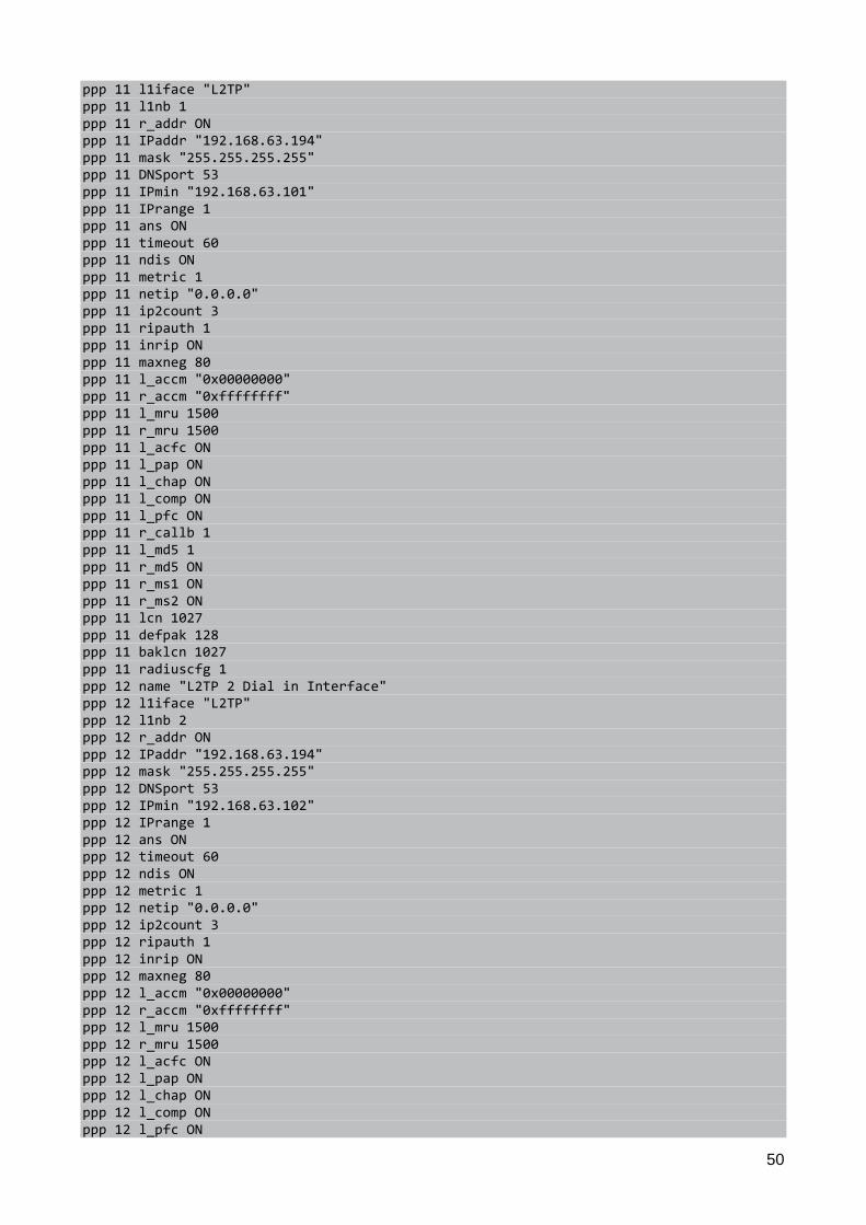
50
ppp 11 l1iface "L2TP" ppp 11 l1nb 1 ppp 11 r_addr ON ppp 11 IPaddr "192.168.63.194" ppp 11 mask "255.255.255.255" ppp 11 DNSport 53 ppp 11 IPmin "192.168.63.101" ppp 11 IPrange 1 ppp 11 ans ON ppp 11 timeout 60 ppp 11 ndis ON ppp 11 metric 1 ppp 11 netip "0.0.0.0" ppp 11 ip2count 3 ppp 11 ripauth 1 ppp 11 inrip ON ppp 11 maxneg 80 ppp 11 l_accm "0x00000000" ppp 11 r_accm "0xffffffff" ppp 11 l_mru 1500 ppp 11 r_mru 1500 ppp 11 l_acfc ON ppp 11 l_pap ON ppp 11 l_chap ON ppp 11 l_comp ON ppp 11 l_pfc ON ppp 11 r_callb 1 ppp 11 l_md5 1 ppp 11 r_md5 ON ppp 11 r_ms1 ON ppp 11 r_ms2 ON ppp 11 lcn 1027 ppp 11 defpak 128 ppp 11 baklcn 1027 ppp 11 radiuscfg 1 ppp 12 name "L2TP 2 Dial in Interface" ppp 12 l1iface "L2TP" ppp 12 l1nb 2 ppp 12 r_addr ON ppp 12 IPaddr "192.168.63.194" ppp 12 mask "255.255.255.255" ppp 12 DNSport 53 ppp 12 IPmin "192.168.63.102" ppp 12 IPrange 1 ppp 12 ans ON ppp 12 timeout 60 ppp 12 ndis ON ppp 12 metric 1 ppp 12 netip "0.0.0.0" ppp 12 ip2count 3 ppp 12 ripauth 1 ppp 12 inrip ON ppp 12 maxneg 80 ppp 12 l_accm "0x00000000" ppp 12 r_accm "0xffffffff" ppp 12 l_mru 1500 ppp 12 r_mru 1500 ppp 12 l_acfc ON ppp 12 l_pap ON ppp 12 l_chap ON ppp 12 l_comp ON ppp 12 l_pfc ON

51
ppp 12 r_callb 1 ppp 12 l_md5 1 ppp 12 r_md5 ON ppp 12 r_ms1 ON ppp 12 r_ms2 ON ppp 12 lcn 1027 ppp 12 defpak 128 ppp 12 baklcn 1027 ppp 12 radiuscfg 1 ppp 13 name "L2TP 3 Dial in Interface" ppp 13 l1iface "L2TP" ppp 13 l1nb 3 ppp 13 r_addr ON ppp 13 IPaddr "192.168.63.194" ppp 13 mask "255.255.255.255" ppp 13 DNSport 53 ppp 13 IPmin "192.168.63.103" ppp 13 IPrange 1 ppp 13 ans ON ppp 13 timeout 60 ppp 13 ndis ON ppp 13 metric 1 ppp 13 netip "0.0.0.0" ppp 13 ip2count 3 ppp 13 ripauth 1 ppp 13 inrip ON ppp 13 maxneg 80 ppp 13 l_accm "0x00000000" ppp 13 r_accm "0xffffffff" ppp 13 l_mru 1500 ppp 13 r_mru 1500 ppp 13 l_acfc ON ppp 13 l_pap ON ppp 13 l_chap ON ppp 13 l_comp ON ppp 13 l_pfc ON ppp 13 r_callb 1 ppp 13 l_md5 1 ppp 13 r_md5 ON ppp 13 r_ms1 ON ppp 13 r_ms2 ON ppp 13 lcn 1027 ppp 13 defpak 128 ppp 13 baklcn 1027 ppp 13 radiuscfg 1 ppp 14 name "L2TP 4 Dial in Interface" ppp 14 l1iface "L2TP" ppp 14 l1nb 4 ppp 14 r_addr ON ppp 14 IPaddr "192.168.63.194" ppp 14 mask "255.255.255.255" ppp 14 DNSport 53 ppp 14 IPmin "192.168.63.104" ppp 14 IPrange 1 ppp 14 ans ON ppp 14 timeout 60 ppp 14 ndis ON ppp 14 metric 1 ppp 14 netip "0.0.0.0" ppp 14 ip2count 3 ppp 14 ripauth 1 ppp 14 inrip ON

52
ppp 14 maxneg 80 ppp 14 l_accm "0x00000000" ppp 14 r_accm "0xffffffff" ppp 14 l_mru 1500 ppp 14 r_mru 1500 ppp 14 l_acfc ON ppp 14 l_pap ON ppp 14 l_chap ON ppp 14 l_comp ON ppp 14 l_pfc ON ppp 14 r_callb 1 ppp 14 l_md5 1 ppp 14 r_md5 ON ppp 14 r_ms1 ON ppp 14 r_ms2 ON ppp 14 lcn 1027 ppp 14 defpak 128 ppp 14 baklcn 1027 ppp 14 radiuscfg 1 ppp 15 name "L2TP 5 Dial in Interface" ppp 15 l1iface "L2TP" ppp 15 l1nb 5 ppp 15 r_addr ON ppp 15 IPaddr "192.168.63.194" ppp 15 mask "255.255.255.255" ppp 15 DNSport 53 ppp 15 IPmin "192.168.63.105" ppp 15 IPrange 1 ppp 15 ans ON ppp 15 timeout 60 ppp 15 ndis ON ppp 15 metric 1 ppp 15 netip "0.0.0.0" ppp 15 ip2count 3 ppp 15 ripauth 1 ppp 15 inrip ON ppp 15 maxneg 80 ppp 15 l_accm "0x00000000" ppp 15 r_accm "0xffffffff" ppp 15 l_mru 1500 ppp 15 r_mru 1500 ppp 15 l_acfc ON ppp 15 l_pap ON ppp 15 l_chap ON ppp 15 l_comp ON ppp 15 l_pfc ON ppp 15 r_callb 1 ppp 15 l_md5 1 ppp 15 r_md5 ON ppp 15 r_ms1 ON ppp 15 r_ms2 ON ppp 15 lcn 1027 ppp 15 defpak 128 ppp 15 baklcn 1027 ppp 15 radiuscfg 1 ppp 16 name "L2TP 6 Dial in Interface" ppp 16 l1iface "L2TP" ppp 16 l1nb 6 ppp 16 r_addr ON ppp 16 IPaddr "192.168.63.194" ppp 16 mask "255.255.255.255" ppp 16 DNSport 53

53
ppp 16 IPmin "192.168.63.106" ppp 16 IPrange 1 ppp 16 ans ON ppp 16 timeout 60 ppp 16 ndis ON ppp 16 metric 1 ppp 16 netip "0.0.0.0" ppp 16 ip2count 3 ppp 16 ripauth 1 ppp 16 inrip ON ppp 16 maxneg 80 ppp 16 l_accm "0x00000000" ppp 16 r_accm "0xffffffff" ppp 16 l_mru 1500 ppp 16 r_mru 1500 ppp 16 l_acfc ON ppp 16 l_pap ON ppp 16 l_chap ON ppp 16 l_comp ON ppp 16 l_pfc ON ppp 16 r_callb 1 ppp 16 l_md5 1 ppp 16 r_md5 ON ppp 16 r_ms1 ON ppp 16 r_ms2 ON ppp 16 lcn 1027 ppp 16 defpak 128 ppp 16 baklcn 1027 ppp 16 radiuscfg 1 ppp 17 name "L2TP 7 Dial in Interface" ppp 17 l1iface "L2TP" ppp 17 l1nb 7 ppp 17 r_addr ON ppp 17 IPaddr "192.168.63.194" ppp 17 mask "255.255.255.255" ppp 17 DNSport 53 ppp 17 IPmin "192.168.63.107" ppp 17 IPrange 1 ppp 17 ans ON ppp 17 timeout 60 ppp 17 ndis ON ppp 17 metric 1 ppp 17 netip "0.0.0.0" ppp 17 ip2count 3 ppp 17 ripauth 1 ppp 17 inrip ON ppp 17 maxneg 80 ppp 17 l_accm "0x00000000" ppp 17 r_accm "0xffffffff" ppp 17 l_mru 1500 ppp 17 r_mru 1500 ppp 17 l_acfc ON ppp 17 l_pap ON ppp 17 l_chap ON ppp 17 l_comp ON ppp 17 l_pfc ON ppp 17 r_callb 1 ppp 17 l_md5 1 ppp 17 r_md5 ON ppp 17 r_ms1 ON ppp 17 r_ms2 ON ppp 17 lcn 1027
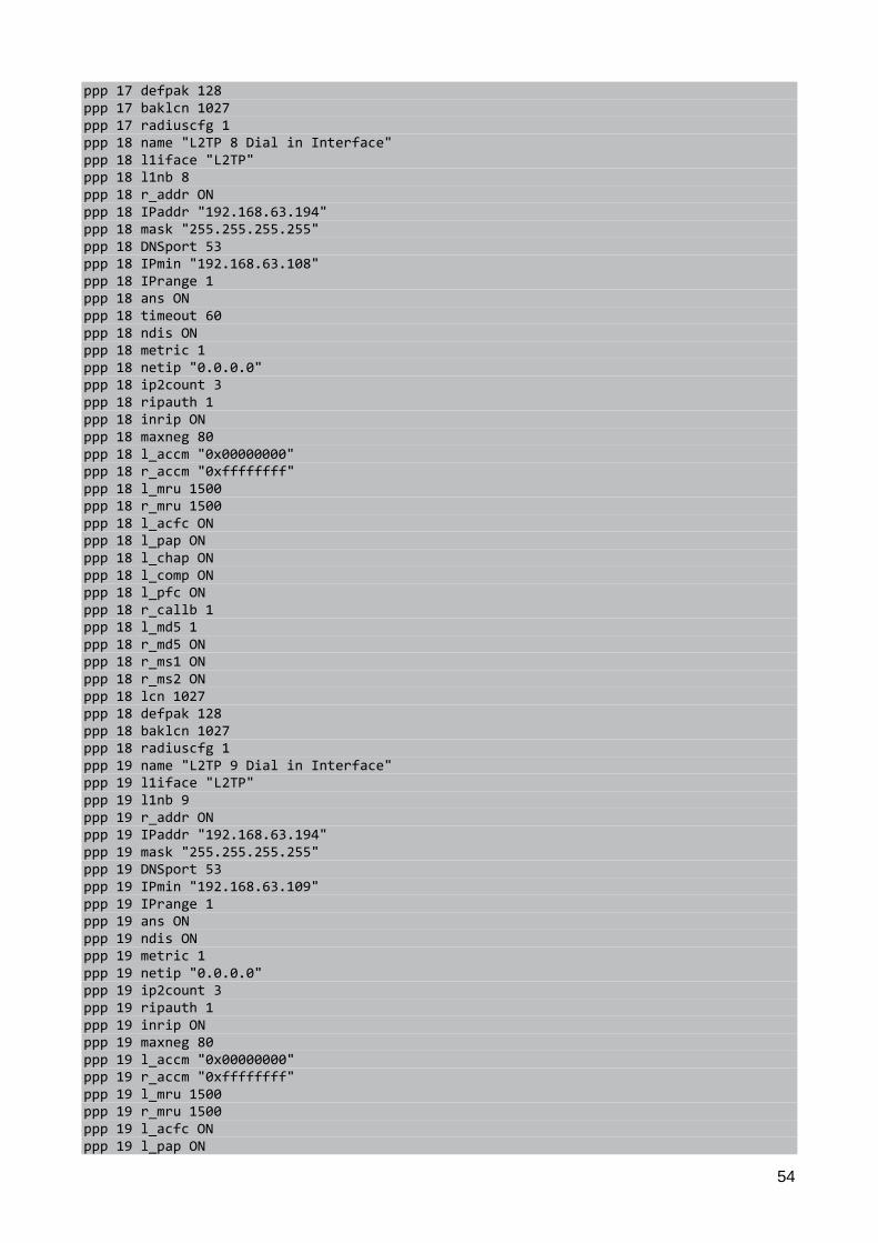
54
ppp 17 defpak 128 ppp 17 baklcn 1027 ppp 17 radiuscfg 1 ppp 18 name "L2TP 8 Dial in Interface" ppp 18 l1iface "L2TP" ppp 18 l1nb 8 ppp 18 r_addr ON ppp 18 IPaddr "192.168.63.194" ppp 18 mask "255.255.255.255" ppp 18 DNSport 53 ppp 18 IPmin "192.168.63.108" ppp 18 IPrange 1 ppp 18 ans ON ppp 18 timeout 60 ppp 18 ndis ON ppp 18 metric 1 ppp 18 netip "0.0.0.0" ppp 18 ip2count 3 ppp 18 ripauth 1 ppp 18 inrip ON ppp 18 maxneg 80 ppp 18 l_accm "0x00000000" ppp 18 r_accm "0xffffffff" ppp 18 l_mru 1500 ppp 18 r_mru 1500 ppp 18 l_acfc ON ppp 18 l_pap ON ppp 18 l_chap ON ppp 18 l_comp ON ppp 18 l_pfc ON ppp 18 r_callb 1 ppp 18 l_md5 1 ppp 18 r_md5 ON ppp 18 r_ms1 ON ppp 18 r_ms2 ON ppp 18 lcn 1027 ppp 18 defpak 128 ppp 18 baklcn 1027 ppp 18 radiuscfg 1 ppp 19 name "L2TP 9 Dial in Interface" ppp 19 l1iface "L2TP" ppp 19 l1nb 9 ppp 19 r_addr ON ppp 19 IPaddr "192.168.63.194" ppp 19 mask "255.255.255.255" ppp 19 DNSport 53 ppp 19 IPmin "192.168.63.109" ppp 19 IPrange 1 ppp 19 ans ON ppp 19 ndis ON ppp 19 metric 1 ppp 19 netip "0.0.0.0" ppp 19 ip2count 3 ppp 19 ripauth 1 ppp 19 inrip ON ppp 19 maxneg 80 ppp 19 l_accm "0x00000000" ppp 19 r_accm "0xffffffff" ppp 19 l_mru 1500 ppp 19 r_mru 1500 ppp 19 l_acfc ON ppp 19 l_pap ON

55
ppp 19 l_chap ON ppp 19 l_comp ON ppp 19 l_pfc ON ppp 19 r_callb 1 ppp 19 l_md5 1 ppp 19 r_md5 ON ppp 19 r_ms1 ON ppp 19 r_ms2 ON ppp 19 lcn 1027 ppp 19 defpak 128 ppp 19 baklcn 1027 ppp 19 radiuscfg 1 web 0 prelogin_info ON web 0 showgswiz ON ftpcli 0 hostname "ftp1.digi.com" ftpcli 0 directory "support/firmware/transport/MC7354_carrier_firmware" modemcc 0 info_asy_add 7 modemcc 0 apn "mw01.vzwstatic" modemcc 0 link_retries 30 modemcc 0 stat_retries 30 modemcc 0 sms_interval 1 modemcc 0 sms_access 1 modemcc 0 sms_concat 0 modemcc 0 apn_2 "none" modemcc 0 link_retries_2 30 modemcc 0 stat_retries_2 30 modemcc 0 sms_interval_2 1 modemcc 0 sms_access_2 1 modemcc 0 sms_concat_2 0 ana 0 l2on OFF ana 0 l3on OFF ana 0 xoton OFF ana 0 lapdon 0 ana 0 lapbon 0 ana 0 maxdata 1500 ana 0 logsize 180 cmd 0 unitid "ss%s>" cmd 0 cmdnua "99" cmd 0 hostname "digi.router" cmd 0 tremto 1200 user 0 access 0 user 1 name "AN21AdminUser" user 1 access 0 user 2 name "Remote_User_Static" user 2 access 4 user 2 fieldip "192.168.63.10" user 2 IPaddr "255.255.255.255" user 3 access 0 user 4 access 0 user 5 access 0 user 6 access 0 user 7 access 0 user 8 access 0 user 9 name "Remote_User_1" user 9 access 4 user 14 name "*" user 14 access 4 user 14 dun_en OFF local 0 transaccess 2 sslcli 0 verify 10 sslsvr 0 certfile "cert01.pem" sslsvr 0 keyfile "privrsa.pem"

56
ssh 0 hostkey1 "privSSH.pem" ssh 0 nb_listen 5 ssh 0 v1 OFF cloud 0 ssl ON [ENDCFG] OK
5.2 TransPort firmware version
Command: ati5 Command result Digi TransPort WR44-L500-NE1-SU Ser#:524627 HW Revision: 2202a Software Build Ver5.2.14.5. Apr 26 2016 11:51:34 LW ARM Bios Ver 7.56u v45 800MHz B995-M1003-F80-O1,0 MAC:00042d080153 Power Up Profile: 0 Async Driver Revision: 1.19 Int clk Wi-Fi Revision: 2.0 Ethernet Hub Driver Revision: 1.11 Firewall Revision: 1.0 EventEdit Revision: 1.0 Timer Module Revision: 1.1 (B)USBHOST Revision: 1.0 L2TP Revision: 1.10 PPTP Revision: 1.00 TACPLUS Revision: 1.00 MODBUS Revision: 0.00 MySQL Revision: 0.01 RealPort Revision: 0.00 MultiTX Revision: 1.00 LAPB Revision: 1.12 X25 Layer Revision: 1.19 MACRO Revision: 1.0 PAD Revision: 1.4 X25 Switch Revision: 1.7 V120 Revision: 1.16 TPAD Interface Revision: 1.12 GPS Revision: 1.0 TELITUPD Revision: 1.0 SCRIBATSK Revision: 1.0 BASTSK Revision: 1.0 PYTHON Revision: 1.0 CLOUDSMS Revision: 1.0 ARM Sync Driver Revision: 1.18 TCP (HASH mode) Revision: 1.14 TCP Utils Revision: 1.13 PPP Revision: 5.2 WEB Revision: 1.5 SMTP Revision: 1.1 FTP Client Revision: 1.5 FTP Revision: 1.4 IKE Revision: 1.0 PollANS Revision: 1.2 PPPOE Revision: 1.0 BRIDGE Revision: 1.1 MODEM CC (SIERRA LTE) Revision: 5.2 FLASH Write Revision: 1.2 Command Interpreter Revision: 1.38 SSLCLI Revision: 1.0 OSPF Revision: 1.0 BGP Revision: 1.0

57
QOS Revision: 1.0 PWRCTRL Revision: 1.0 RADIUS Client Revision: 1.0 SSH Server Revision: 1.0 SCP Revision: 1.0 SSH Client Revision: 1.0 CERT Revision: 1.0 LowPrio Revision: 1.0 Tunnel Revision: 1.2 OVPN Revision: 1.2 TEMPLOG Revision: 1.0 QDL Revision: 1.0 OK