Embed Size (px)
Citation preview
Protection for Local Area Networks (LAN)
Application Note AN004 for ESP Cat-5, ESP Cat-5e, ESP Cat-5/Gigabit, ESP Cat-5e/Gigabit & ESP Cat-5/PoE
Protection for local area networks (LAN)
2 AN00416715 | Application Notes - Protection for Local Area Networks (LAN)
ESP LAN Series protectors offer combined Category C, B tested protection (to BS EN/IEC 61643-21), for twisted pair Ethernet networks with RJ45 connections, including Power over Ethernet (PoE).
Suitable for systems signalling on up to eight wires of either shielded or unshielded twisted pair cable, ESP Cat-5 Series protectors operate in Full Mode, capable of handling partial lightning currents as well as allowing continual operation of protected equipment.
Protectors include as standard:
– Very low let-through voltage (enhanced protection to BS EN 62305) between all lines
– Effective protection without impairing the system’s normal operation
– Repeated protection in lightning intense environments – Low capacitance circuitry to
prevent the start-up signal degradation associated with other types of network protector
– Low in-line resistance to minimise unnecessary reductions in signal strength, to maximise signalling distance – Convenient holes for flat mounting,
or vertical mounting via TS35 ‘Top Hat’ DIN rail
Installation
For use at boundaries up to LPZ 0B to protect against flashover (typically the service entrance location) through to LPZ 3 to protect sensitive electronic equipment.
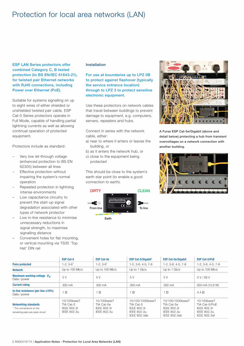
Use these protectors on network cables that travel between buildings to prevent damage to equipment, e.g. computers, servers, repeaters and hubs.
Connect in series with the network cable, either:a) near to where it enters or leaves the building, orb) as it enters the network hub, orc) close to the equipment being protected
This should be close to the system’s earth star point (to enable a good connection to earth).
A Furse ESP Cat-5e/Gigabit (above and
detail below) protecting a hub from transient
overvoltages on a network connection with
another building.
ELECTRONIC SYSTEMS PROTECTION
Plug-in Lightning Barrier
Wilford Road,Nottingham,NG2 1EB, UK
DIRTY
enil oTenil morF
Earth
CLEAN
Pairs protected 1-2, 3-6
10/100baseTTIA Cat-5IEEE 802.3iIEEE 802.3u
10/100baseTTIA Cat-5eIEEE 802.3iIEEE 802.3u
10/100/1000baseTTIA Cat-5IEEE 802.3iIEEE 802.3uIEEE 802.3ab
10/100/1000baseTTIA Cat-5eIEEE 802.3iIEEE 802.3uIEEE 802.3ab
10/100baseTTIA Cat-5/PoEIEEE 802.3iIEEE 802.3uIEEE 802.3af
1 1-2, 3-61 1-2, 3-6, 4-5, 7-8 1-2, 3-6, 4-5, 7-8 1-2, 3-6, 4-5, 7-8
Network Up to 100 Mb/s Up to 100 Mb/s Up to 1 Gb/s Up to 1 Gb/s Up to 100 Mb/s
V 85
/
V
5
V
5 V5 V5 V5Maximum working voltage U c
rewop / ataD
Current rating 300 mA 300 mA 300 mA 300 mA
In-line resistance (per line ±10%)
1
rewop / ataDΩ 1 Ω 1 Ω 1 Ω 4.4 Ω
Networking standards1 The connections on the
remaining pairs are open circuit
350 mA (15.6 W)
ESP Cat-5 ESP Cat-5e ESP Cat-5/Gigabit1 ESP Cat-5e/Gigabit ESP Cat-5/PoE
Application Notes - Protection for Local Area Networks (LAN) | AN00416715 3
The ESP Cat-5e andESP Cat-5e/Gigabit
These lightning barriers have beendesigned to cater for high endnetworking systems that demand theincreased performance of Cat-5e cabling.
The attenuation on the communicationpairs is lower on these barriers compared to the rest of the networking barriers as higher specification components are used throughout.
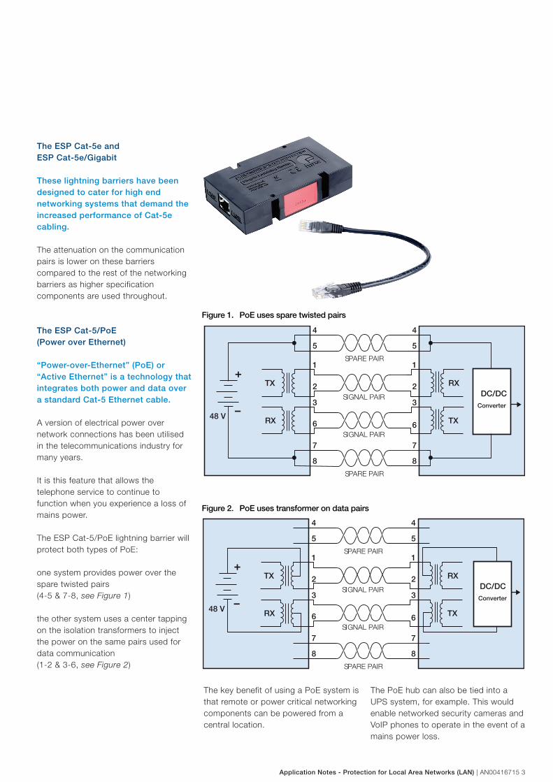
The ESP Cat-5/PoE(Power over Ethernet)
“Power-over-Ethernet” (PoE) or “Active Ethernet” is a technology that integrates both power and data over a standard Cat-5 Ethernet cable.
A version of electrical power over network connections has been utilised in the telecommunications industry for many years.
It is this feature that allows the telephone service to continue to function when you experience a loss of mains power.
The ESP Cat-5/PoE lightning barrier willprotect both types of PoE:
one system provides power over the spare twisted pairs (4-5 & 7-8, see Figure 1)
the other system uses a center tappingon the isolation transformers to injectthe power on the same pairs used fordata communication (1-2 & 3-6, see Figure 2)
4
SPARE PAIR
DC/DCConverter
+
–SIGNAL PAIR
RXTX
48 V
4
55
7
SPARE PAIR
7
88
11
22
33
SIGNAL PAIR
TXRX 6 6
4
SPARE PAIR
+
–SIGNAL PAIR
RXTX
48 V
4
55
7
SPARE PAIR
7
88
11
22
33
SIGNAL PAIR
TXRX 6 6
DC/DCConverter
Figure 1. PoE uses spare twisted pairs
Figure 2. PoE uses transformer on data pairs
The key benefit of using a PoE system is that remote or power critical networking components can be powered from a central location.
The PoE hub can also be tied into a UPS system, for example. This would enable networked security cameras and VoIP phones to operate in the event of a mains power loss.

© C
opyr
ight
AB
B 2
015 9A
AK10
103A
5595
Electronic Systems ProtectionEquipotential bonding and transientovervoltage surge protection
Electronic Systems ProtectionEquipotential bonding and transientovervoltage surge protection
Contact us
ABB FurseUK OfficeWilford RoadNottingham NG2 1EBTel: +44 (0) 115 964 3700Fax: +44 (0) 115 986 0071 Sales Tel: +44 (0) 333 999 9900Sales Fax: +44 (0) 333 999 9901E-Mail: [email protected]
www.furse.com
Note: We reserve the right to make technical changes or modify the contents of this document without prior notice. With regard to purchase orders, the agreed particulars shall prevail. ABB AG does not accept any responsibility whatsoever for potential errors or possible lack of information in this document.
We reserve all rights in this document and in the subject matter and illustrations contained therein. Any reproduction, disclosureto third parties or utilization of its contents – in whole or in parts – is forbidden without prior written consent of ABB AG.
Copyright © 2015 ABBAll rights reserved