Embed Size (px)
Citation preview
PG; Reviewed:
SPOC 5/9/2014
Solution & Interoperability Test Lab Application Notes
©2014 Avaya Inc. All Rights Reserved.
1 of 58
Pres10AES63
Avaya Solution & Interoperability Test Lab
Application Notes for Configuring Presence Technology
Presence Suite R10.0 with Avaya Aura® Communication
Manager R6.3 and Avaya Aura® Application Enablement
Services R6.3 – Issue 1.0
Abstract
These Application Notes describe the configuration steps for Presence Technology Presence
Suite to successfully interoperate with Avaya Aura® Communication Manager and Avaya
Aura® Application Enablement Services. Presence Suite is a multi-channel contact
management suite which handles voice, text chat, email and web contact mechanisms. Presence
Suite integrates with the Avaya solution by using the Telephony Services Application
Programming Interface (TSAPI) provided by Avaya Aura® Application Enablement Services
to monitor and control agent stations, and handle routing of external calls.
Information in these Application Notes has been obtained through DevConnect Compliance
Testing and additional technical discussions. Testing was conducted via the DevConnect
Program at the Avaya Solution and Interoperability Test Lab.

PG; Reviewed:
SPOC 5/9/2014
Solution & Interoperability Test Lab Application Notes
©2014 Avaya Inc. All Rights Reserved.
2 of 58
Pres10AES63
1 Introduction These Application Notes describe the compliance tested configuration using Presence Suite
R10.0 and Avaya Aura® Communication Manager R6.3 with Avaya Aura® Application
Enablement Services R6.3 (AES). Presence Suite is a multi-channel contact management suite
able to handle voice, e-mail and web chat contact mechanisms. The Telephony Services
Application Programming Interface (TSAPI) provided by Avaya Aura® Application Enablement
Services is used to monitor and control agent stations, generate phantom calls for non-voice
contacts and handle routing of external calls. Presence Suite consists of a number of modules.
Only the following modules were tested.
Presence Voice Outbound
Presence Voice Inbound
Presence Mail Interactions
Presence Web Interactions
Link Failure\Recovery was also tested to ensure successful reconnection on link failure. Upon
starting the Presence Server application, the application automatically queries Avaya Aura®
Application Enablement Services for device status and requests monitoring. The Presence Server
specifies where to route each call and hence how to handle the calls, based on agent status
information that the application tracks from CTI device query results and event reports received
from Avaya Aura® Application Enablement Services.
2 General Test Approach and Test Results Testing included validating the correct operation of typical contact centre functions including,
inbound and outbound service calls. Functionality testing included basic telephony operations
such as answer, hold/retrieve, transfer, and conference. This was carried out for the inbound and
outbound service calls. Email, Web call back and Web chat were also tested. Additional features
such as call capturing, direct agent transfer and malicious calls were tested. The serviceability
test cases were performed manually by busying out and releasing the CTI link and by
disconnecting and reconnecting LAN cables.
Note: Only call control of H.323 stations is possible, no SIP stations were used in the
compliance testing.
DevConnect Compliance Testing is conducted jointly by Avaya and DevConnect members. The
jointly-defined test plan focuses on exercising APIs and/or standards-based interfaces pertinent
to the interoperability of the tested products and their functionalities. DevConnect Compliance
Testing is not intended to substitute full product performance or feature testing performed by
DevConnect members, nor is it to be construed as an endorsement by Avaya of the suitability or
completeness of a DevConnect member’s solution.
PG; Reviewed:
SPOC 5/9/2014
Solution & Interoperability Test Lab Application Notes
©2014 Avaya Inc. All Rights Reserved.
3 of 58
Pres10AES63
2.1 Interoperability Compliance Testing
The interoperability compliance test included both feature functionality and serviceability
testing. The feature functionality testing focused on verifying Presence Suite handling of TSAPI
messages in the areas of routing, call control and event notification. The serviceability testing
focused on verifying the Presence Suite ability to recover from adverse conditions, such as
stopping the TSAPI Service, taking the CTI link offline and disconnecting the Ethernet cable
from all the devices in the solution.
2.2 Test Results
All test cases passed successfully.
2.3 Support
Technical support can be obtained for Presence Technology Presence Suite as follows:
Email: [email protected]
Website: www.presenceco.com
Phone: +34 93 10 10 300

PG; Reviewed:
SPOC 5/9/2014
Solution & Interoperability Test Lab Application Notes
©2014 Avaya Inc. All Rights Reserved.
4 of 58
Pres10AES63
3 Reference Configuration Figure 1 shows the network topology during interoperability testing. A Communication
Manager with an Avaya G430 Media Gateway was used as the hosting PBX. Presence Suite,
including Presence Agent PC’s, are connected to the LAN and control the Avaya H.323 IP
telephones via Application Enablement Services using TSAPI.
Figure 1: Avaya Aura® Communication Manager R6.3 with Aura® Application
Enablement Services R6.3 and Presence Technology Presence Suite Server configuration

PG; Reviewed:
SPOC 5/9/2014
Solution & Interoperability Test Lab Application Notes
©2014 Avaya Inc. All Rights Reserved.
5 of 58
Pres10AES63
4 Equipment and Software Validated All the hardware and associated software used in the compliance testing is listed below.
Equipment/Software Release/Version
Avaya Aura® System Manager running on
Avaya S8800 Server
System Manager 6.3.0 - FP2
Build No. - 6.3.0.8.5682-6.3.8.1814
Software Update Revision No:
6.3.3.5.1719
Avaya Aura® Communication Manager running
on Avaya S8800 Server
R6.3 SP1
R016x.03.0.124.0
Avaya Aura® Application Enablement Services
running on Avaya S8800 Server
R6.3
Build No - 6.3.0.0.212-0
Avaya G430 Gateway R6.3
Avaya 96xx Series Deskphone 96xx H.323 Release 3.1 SP2
Presence Server running on Windows Server
2008 SP2 R10.0
Presence Client running on Windows XP and
Windows Server 2008 SP2 R10.0
PG; Reviewed:
SPOC 5/9/2014
Solution & Interoperability Test Lab Application Notes
©2014 Avaya Inc. All Rights Reserved.
6 of 58
Pres10AES63
5 Configure Avaya Aura® Communication Manager
The information provided in this section describes the configuration of Communication Manager
for this solution. For all other provisioning information such as initial installation and
configuration, please refer to the product documentation in Section 10. The configuration and
verification operations illustrated in this section were all performed using Communication
Manager System Administration Terminal (SAT). The configuration operations described in this
section can be summarized as follows:
Verify System Features
Administer Special Information Tones (SIT) Treatment for Call Classification
Define Feature Access Codes (FAC)
Administer Trunk Group
Administer Hunt Groups, Vectors and VDN’s
Administer Class of Restriction
Administer Agent Logins
Administer Agent Stations
Administer Phantom Stations
Note procr IP Address for AES Connectivity
Configure Transport link for AES Connectivity
Configure CTI Link for TSAPI Service
PG; Reviewed:
SPOC 5/9/2014
Solution & Interoperability Test Lab Application Notes
©2014 Avaya Inc. All Rights Reserved.
7 of 58
Pres10AES63
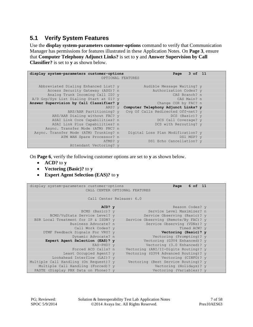
5.1 Verify System Features
Use the display system-parameters customer-options command to verify that Communication
Manager has permissions for features illustrated in these Application Notes. On Page 3, ensure
that Computer Telephony Adjunct Links? is set to y and Answer Supervision by Call
Classifier? is set to y as shown below.
display system-parameters customer-options Page 3 of 11
OPTIONAL FEATURES
Abbreviated Dialing Enhanced List? y Audible Message Waiting? y
Access Security Gateway (ASG)? n Authorization Codes? y
Analog Trunk Incoming Call ID? y CAS Branch? n
A/D Grp/Sys List Dialing Start at 01? y CAS Main? n
Answer Supervision by Call Classifier? y Change COR by FAC? n
ARS? y Computer Telephony Adjunct Links? y
ARS/AAR Partitioning? y Cvg Of Calls Redirected Off-net? y
ARS/AAR Dialing without FAC? y DCS (Basic)? y
ASAI Link Core Capabilities? n DCS Call Coverage? y
ASAI Link Plus Capabilities? n DCS with Rerouting? y
Async. Transfer Mode (ATM) PNC? n
Async. Transfer Mode (ATM) Trunking? n Digital Loss Plan Modification? y
ATM WAN Spare Processor? n DS1 MSP? y
ATMS? y DS1 Echo Cancellation? y
Attendant Vectoring? y
On Page 6, verify the following customer options are set to y as shown below.
ACD? to y
Vectoring (Basic)? to y
Expert Agent Selection (EAS)? to y
display system-parameters customer-options Page 6 of 11
CALL CENTER OPTIONAL FEATURES
Call Center Release: 6.0
ACD? y Reason Codes? y
BCMS (Basic)? y Service Level Maximizer? n
BCMS/VuStats Service Level? y Service Observing (Basic)? y
BSR Local Treatment for IP & ISDN? y Service Observing (Remote/By FAC)? y
Business Advocate? n Service Observing (VDNs)? y
Call Work Codes? y Timed ACW? y
DTMF Feedback Signals For VRU? y Vectoring (Basic)? y
Dynamic Advocate? n Vectoring (Prompting)? y
Expert Agent Selection (EAS)? y Vectoring (G3V4 Enhanced)? y
EAS-PHD? y Vectoring (3.0 Enhanced)? y
Forced ACD Calls? n Vectoring (ANI/II-Digits Routing)? y
Least Occupied Agent? y Vectoring (G3V4 Advanced Routing)? y
Lookahead Interflow (LAI)? y Vectoring (CINFO)? y
Multiple Call Handling (On Request)? y Vectoring (Best Service Routing)? y
Multiple Call Handling (Forced)? y Vectoring (Holidays)? y
PASTE (Display PBX Data on Phone)? y Vectoring (Variables)? y
PG; Reviewed:
SPOC 5/9/2014
Solution & Interoperability Test Lab Application Notes
©2014 Avaya Inc. All Rights Reserved.
8 of 58
Pres10AES63
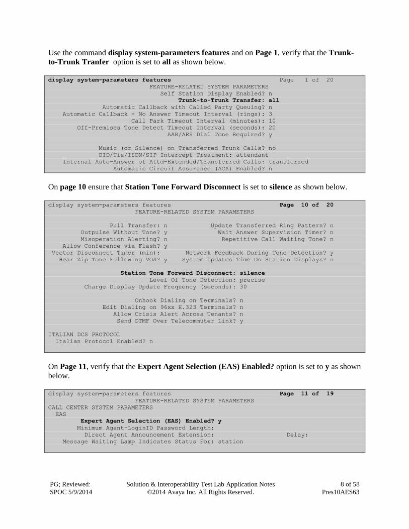
Use the command display system-parameters features and on Page 1, verify that the Trunk-
to-Trunk Tranfer option is set to all as shown below.
display system-parameters features Page 1 of 20
FEATURE-RELATED SYSTEM PARAMETERS
Self Station Display Enabled? n
Trunk-to-Trunk Transfer: all
Automatic Callback with Called Party Queuing? n
Automatic Callback - No Answer Timeout Interval (rings): 3
Call Park Timeout Interval (minutes): 10
Off-Premises Tone Detect Timeout Interval (seconds): 20
AAR/ARS Dial Tone Required? y
Music (or Silence) on Transferred Trunk Calls? no
DID/Tie/ISDN/SIP Intercept Treatment: attendant
Internal Auto-Answer of Attd-Extended/Transferred Calls: transferred
Automatic Circuit Assurance (ACA) Enabled? n
On page 10 ensure that Station Tone Forward Disconnect is set to silence as shown below.
display system-parameters features Page 10 of 20
FEATURE-RELATED SYSTEM PARAMETERS
Pull Transfer: n Update Transferred Ring Pattern? n
Outpulse Without Tone? y Wait Answer Supervision Timer? n
Misoperation Alerting? n Repetitive Call Waiting Tone? n
Allow Conference via Flash? y
Vector Disconnect Timer (min): Network Feedback During Tone Detection? y
Hear Zip Tone Following VOA? y System Updates Time On Station Displays? n
Station Tone Forward Disconnect: silence
Level Of Tone Detection: precise
Charge Display Update Frequency (seconds): 30
Onhook Dialing on Terminals? n
Edit Dialing on 96xx H.323 Terminals? n
Allow Crisis Alert Across Tenants? n
Send DTMF Over Telecommuter Link? y
ITALIAN DCS PROTOCOL
Italian Protocol Enabled? n
On Page 11, verify that the Expert Agent Selection (EAS) Enabled? option is set to y as shown
below.
display system-parameters features Page 11 of 19
FEATURE-RELATED SYSTEM PARAMETERS
CALL CENTER SYSTEM PARAMETERS
EAS
Expert Agent Selection (EAS) Enabled? y
Minimum Agent-LoginID Password Length:
Direct Agent Announcement Extension: Delay:
Message Waiting Lamp Indicates Status For: station
PG; Reviewed:
SPOC 5/9/2014
Solution & Interoperability Test Lab Application Notes
©2014 Avaya Inc. All Rights Reserved.
9 of 58
Pres10AES63
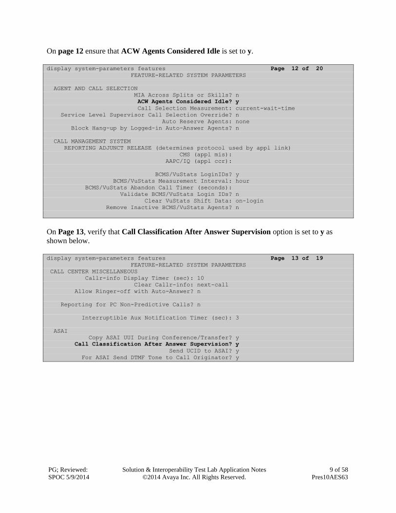
On page 12 ensure that ACW Agents Considered Idle is set to y.
display system-parameters features Page 12 of 20
FEATURE-RELATED SYSTEM PARAMETERS
AGENT AND CALL SELECTION
MIA Across Splits or Skills? n
ACW Agents Considered Idle? y
Call Selection Measurement: current-wait-time
Service Level Supervisor Call Selection Override? n
Auto Reserve Agents: none
Block Hang-up by Logged-in Auto-Answer Agents? n
CALL MANAGEMENT SYSTEM
REPORTING ADJUNCT RELEASE (determines protocol used by appl link)
CMS (appl mis):
AAPC/IQ (appl ccr):
BCMS/VuStats LoginIDs? y
BCMS/VuStats Measurement Interval: hour
BCMS/VuStats Abandon Call Timer (seconds):
Validate BCMS/VuStats Login IDs? n
Clear VuStats Shift Data: on-login
Remove Inactive BCMS/VuStats Agents? n
On Page 13, verify that Call Classification After Answer Supervision option is set to y as
shown below.
display system-parameters features Page 13 of 19
FEATURE-RELATED SYSTEM PARAMETERS
CALL CENTER MISCELLANEOUS
Callr-info Display Timer (sec): 10
Clear Callr-info: next-call
Allow Ringer-off with Auto-Answer? n
Reporting for PC Non-Predictive Calls? n
Interruptible Aux Notification Timer (sec): 3
ASAI
Copy ASAI UUI During Conference/Transfer? y
Call Classification After Answer Supervision? y
Send UCID to ASAI? y
For ASAI Send DTMF Tone to Call Originator? y
PG; Reviewed:
SPOC 5/9/2014
Solution & Interoperability Test Lab Application Notes
©2014 Avaya Inc. All Rights Reserved.
10 of 58
Pres10AES63
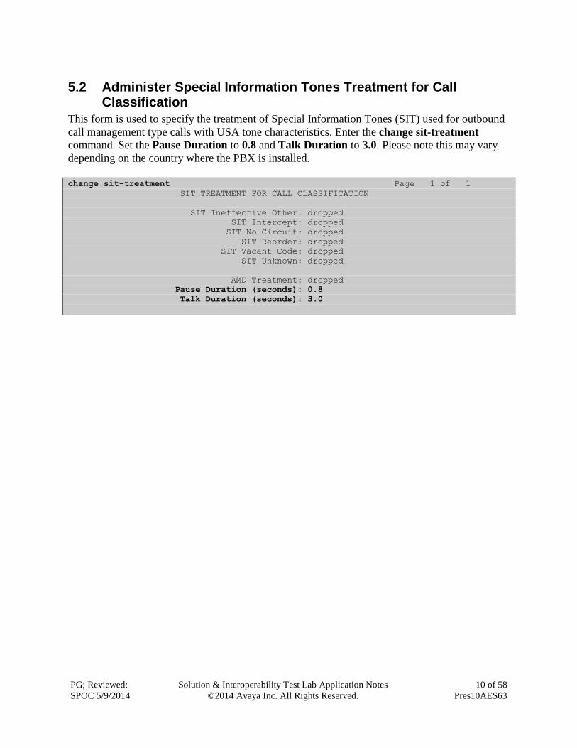
5.2 Administer Special Information Tones Treatment for Call Classification
This form is used to specify the treatment of Special Information Tones (SIT) used for outbound
call management type calls with USA tone characteristics. Enter the change sit-treatment
command. Set the Pause Duration to 0.8 and Talk Duration to 3.0. Please note this may vary
depending on the country where the PBX is installed.
change sit-treatment Page 1 of 1
SIT TREATMENT FOR CALL CLASSIFICATION
SIT Ineffective Other: dropped
SIT Intercept: dropped
SIT No Circuit: dropped
SIT Reorder: dropped
SIT Vacant Code: dropped
SIT Unknown: dropped
AMD Treatment: dropped
Pause Duration (seconds): 0.8
Talk Duration (seconds): 3.0

PG; Reviewed:
SPOC 5/9/2014
Solution & Interoperability Test Lab Application Notes
©2014 Avaya Inc. All Rights Reserved.
11 of 58
Pres10AES63
5.3 Administer Trunk
The PSTN trunk may differ depending on the installation. For the compliance testing, a QSIG
ISDN trunk was used and configured in the following way: Use the change trunk-group n
command, where n is the trunk group number for the pre-configured ISDN trunk which will be
used for inbound and outbound service calls. It is assumed that the ISDN trunk and the
corresponding signaling group are already configured. The trunk group number used for
interoperability testing is 9. On Page 1 set the COR (class of restriction) to 1, this is the COR
used for the sample configuration.
change trunk-group 9 Page 1 of 22
TRUNK GROUP
Group Number: 1 Group Type: isdn CDR Reports: y
Group Name: Simulated PSTN COR: 1 TN: 1 TAC: *19
Direction: two-way Outgoing Display? y Carrier Medium: PRI/BRI
Dial Access? y Busy Threshold: 255 Night Service:
Queue Length: 0
Service Type: tie Auth Code? n TestCall ITC: rest
Far End Test Line No:
TestCall BCC: 4
On Page 3, UUI IE Treatment was set to service-provider (This may differ for a DID trunk
connecting to the carrier in some cases shared is recommended with Maximum Size of UUI IE
Contents set to 32. Default values may be used in the remaining fields.
change trunk-group 2 Page 3 of 22
TRUNK FEATURES
ACA Assignment? n Measured: none Wideband Support? n
Maintenance Tests? y
Data Restriction? n NCA-TSC Trunk Member:
Send Name: n Send Calling Number: n
Used for DCS? n Send EMU Visitor CPN? n
Suppress # Outpulsing? n Format: public
Outgoing Channel ID Encoding: preferred UUI IE Treatment: service-provider
Replace Restricted Numbers? y

PG; Reviewed:
SPOC 5/9/2014
Solution & Interoperability Test Lab Application Notes
©2014 Avaya Inc. All Rights Reserved.
12 of 58
Pres10AES63
5.4 Administer Hunt Groups, Call Vectors and Vector Directory Numbers
In order for calls to be routed to agents, Hunt Groups (skills), Vectors, and Vector Directory
Numbers (VDN) must be configured.
5.4.1 Hunt Groups
Enter the add hunt-group n command where n in the example below is 33. On Page 1 of the
hunt-group form, assign a Group Name and Group Extension valid under the provisioned dial
plan. Set the following options to y as shown below.
ACD? to y
Queue? to y
Vector? to y
add hunt-group 33 Page 1 of 4
HUNT GROUP
Group Number: 33 ACD? y
Group Name: Presenceco Inbound Queue? y
Group Extension: 3330 Vector? y
Group Type: ucd-mia
TN: 1
COR: 1 MM Early Answer? n
Security Code: Local Agent Preference? n
ISDN/SIP Caller Display:
Queue Limit: unlimited
Calls Warning Threshold: Port:
Time Warning Threshold: Port:
On Page 2, set the Skill field to y as shown below.
add hunt-group 33 Page 2 of 4
HUNT GROUP
Skill? y Expected Call Handling Time (sec): 180
AAS? n
Measured: none
Supervisor Extension:
Controlling Adjunct: none
Timed ACW Interval (sec):
Multiple Call Handling: none

PG; Reviewed:
SPOC 5/9/2014
Solution & Interoperability Test Lab Application Notes
©2014 Avaya Inc. All Rights Reserved.
13 of 58
Pres10AES63
Repeat the above steps to create a hunt groups for the outbound service, hunt group 34 is shown
below.
add hunt-group 34 Page 1 of 4
HUNT GROUP
Group Number: 34 ACD? y
Group Name: Presenceco Outbound Queue? y
Group Extension: 3340 Vector? y
Group Type: ucd-mia
TN: 1
COR: 1 MM Early Answer? n
Security Code: Local Agent Preference? n
ISDN/SIP Caller Display:
Queue Limit: unlimited
Calls Warning Threshold: Port:
Time Warning Threshold: Port:
On Page 2, set the Skill field to y as shown below.
add hunt-group 34 Page 2 of 4
HUNT GROUP
Skill? y Expected Call Handling Time (sec): 180
AAS? n
Measured: none
Supervisor Extension:
Controlling Adjunct: none
Timed ACW Interval (sec):
Multiple Call Handling: none
5.4.2 Vectors
Enter the change vector n command, where n is the vector number. The adjunct routing link
enables Presenceco Presence Server to specify the destination of a call. The adjunct routing
link number is defined by the position of the AESVCS link on Page 3 of the ip-services page, as
configured in Section 5.10, in this case Server ID 1. Enter the vector steps to queue to skill 33 as
shown below. Skill 33 relates to the skill enabled hunt group configured previously.
change vector 3 Page 1 of 6
CALL VECTOR
Number: 3 Name: Presenceco In
Multimedia? n Attendant Vectoring? n Meet-me Conf? n Lock? n
Basic? y EAS? y G3V4 Enhanced? y ANI/II-Digits? y ASAI Routing? y
Prompting? y LAI? y G3V4 Adv Route? y CINFO? y BSR? y Holidays? y
Variables? y 3.0 Enhanced? y
01 adjunct routing link 1
02 wait-time 5 secs hearing silence
03 queue-to skill 33 pri m
04 wait-time 999 secs hearing ringback

PG; Reviewed:
SPOC 5/9/2014
Solution & Interoperability Test Lab Application Notes
©2014 Avaya Inc. All Rights Reserved.
14 of 58
Pres10AES63
The above step may should also be used to create a Vector for the Outbound service, as shown
below.
change vector 4 Page 1 of 6
CALL VECTOR
Number: 4 Name: Presenceco Outb
Multimedia? n Attendant Vectoring? n Meet-me Conf? n Lock? n
Basic? y EAS? y G3V4 Enhanced? y ANI/II-Digits? y ASAI Routing? y
Prompting? y LAI? y G3V4 Adv Route? y CINFO? y BSR? y Holidays? y
Variables? y 3.0 Enhanced? y
01 adjunct routing link 1
02 wait-time 5 secs hearing silence
03 queue-to skill 34 pri m
04 wait-time 999 secs hearing ringback
5.4.3 Vector Directory Numbers (VDN)
Enter the add vdn n command, where n is an available extension number. On Page 1 assign a
Name for the VDN and set the Vector Number to the relevant vector.
add vdn 3300 Page 1 of 3
VECTOR DIRECTORY NUMBER
Extension: 3300
Name*: Presenceco Inbound
Destination: Vector Number 3
Attendant Vectoring? n
Meet-me Conferencing? n
Allow VDN Override? n
COR: 1
TN*: 1
Measured: none
VDN of Origin Annc. Extension*:
1st Skill*:
2nd Skill*:
3rd Skill*:
The above step may also be used to create a VDN for the Outbound service, as shown below.
add vdn 3400 Page 1 of 3
VECTOR DIRECTORY NUMBER
Extension: 3400
Name*: Presenceco Outbound
Destination: Vector Number 4
Attendant Vectoring? n
Meet-me Conferencing? n
Allow VDN Override? n
COR: 1
TN*: 1
Measured: none
VDN of Origin Annc. Extension*:
1st Skill*:
2nd Skill*:
3rd Skill*:
PG; Reviewed:
SPOC 5/9/2014
Solution & Interoperability Test Lab Application Notes
©2014 Avaya Inc. All Rights Reserved.
15 of 58
Pres10AES63
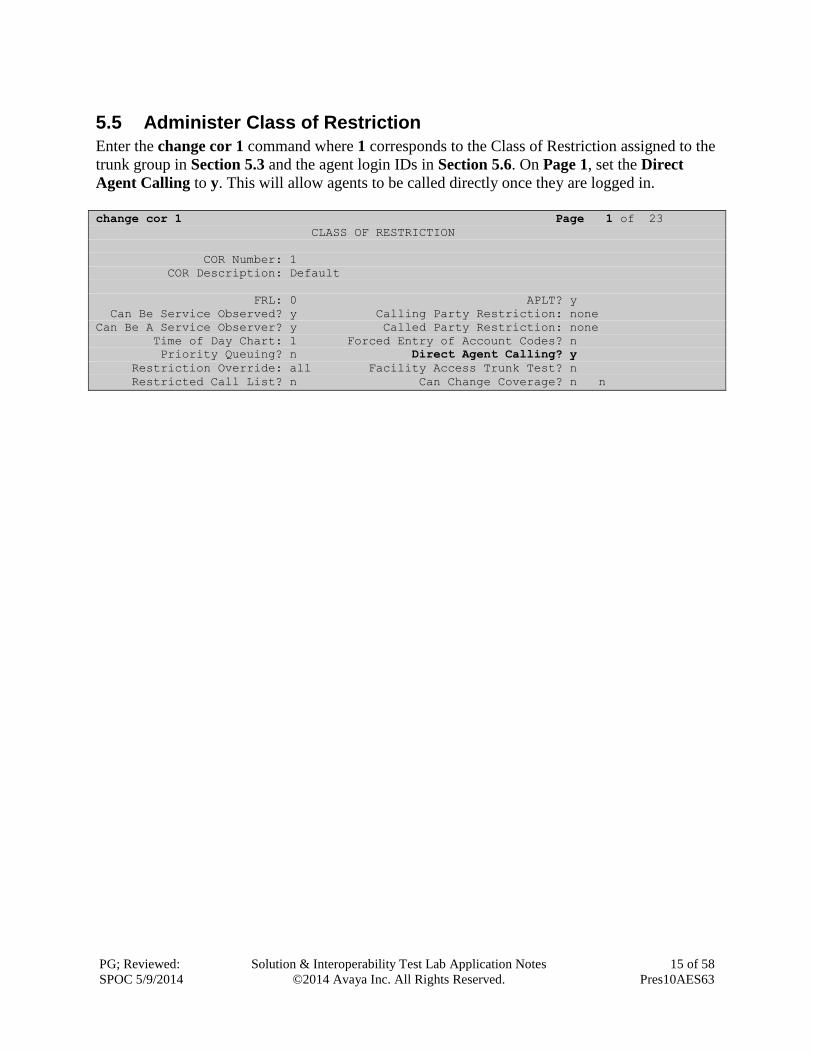
5.5 Administer Class of Restriction
Enter the change cor 1 command where 1 corresponds to the Class of Restriction assigned to the
trunk group in Section 5.3 and the agent login IDs in Section 5.6. On Page 1, set the Direct
Agent Calling to y. This will allow agents to be called directly once they are logged in.
change cor 1 Page 1 of 23
CLASS OF RESTRICTION
COR Number: 1
COR Description: Default
FRL: 0 APLT? y
Can Be Service Observed? y Calling Party Restriction: none
Can Be A Service Observer? y Called Party Restriction: none
Time of Day Chart: 1 Forced Entry of Account Codes? n
Priority Queuing? n Direct Agent Calling? y
Restriction Override: all Facility Access Trunk Test? n
Restricted Call List? n Can Change Coverage? n n

PG; Reviewed:
SPOC 5/9/2014
Solution & Interoperability Test Lab Application Notes
©2014 Avaya Inc. All Rights Reserved.
16 of 58
Pres10AES63
5.6 Administer Agent Logins
Enter the add agent-loginID n command; where n is an available extension number. Enter a
descriptive name for the agent in the Name field. Ensure the COR field is set to 1 which relates
to the COR configured in Section 5.5. The Auto Answer field is set to station except for those
logins that will be used for outbound services. In that case, the field will be set to all. Configure a
password as required.
add agent-loginID 201 Page 1 of 3
AGENT LOGINID
Login ID: 201 AAS? n
Name: Presenceco Agent 1 AUDIX? n
TN: 1 LWC Reception: spe
COR: 1 LWC Log External Calls? n
Coverage Path: AUDIX Name for Messaging:
Security Code:
LoginID for ISDN/SIP Display? n
Password:
Password (enter again):
Auto Answer: station
MIA Across Skills: system
On Page 2, assign a skill to the agent by entering the relevant hunt group number created in
Section 5.4.1 for SN and entering a skill level of 1 for SL. In this case, an agent able to handle
both inbound and outbound calls is created. Set the Direct Agent Skill to the Inbound hunt
group 33.
change agent-loginID 201 Page 2 of 3
AGENT LOGINID
Direct Agent Skill: 33 Service Objective? n
Call Handling Preference: skill-level Local Call Preference? n
SN RL SL SN RL SL SN RL SL SN RL SL
1: 33 1 16: 31: 46:
2: 34 1 17: 32: 47:
Repeat this task accordingly for any additional inbound or outbound agents required.

PG; Reviewed:
SPOC 5/9/2014
Solution & Interoperability Test Lab Application Notes
©2014 Avaya Inc. All Rights Reserved.
17 of 58
Pres10AES63
5.7 Configure Agent Stations
For each station that agents will log in to, enter the command change station n, where n is the
station extension. On Page 4, the following buttons must be assigned as shown below:
aux-work – Agent is logged in to the ACD but is not available to take a call.
manual-in – Agent is available to accept ACD calls.
after-call – Agent state after the ACD call is completed. The agent is not available.
release – State when the call is dropped.
change station 4001 Page 4 of 5
STATION
SITE DATA
Room: Headset? n
Jack: Speaker? n
Cable: Mounting: d
Floor: Cord Length: 0
Building: Set Color:
ABBREVIATED DIALING
List1: List2: List3:
BUTTON ASSIGNMENTS
1: call-appr 5: manual-in Grp:
2: call-appr 6: after-call Grp:
3: call-appr 7: release
4: aux-work RC: Grp: 8::
5.8 Administer Phantom Stations
Presence Suite uses stations via AES to initiate calls on Communication Manager. These stations
will be used to place calls to customers for outbound services as well as to place calls to agents
in order to reserve an agent to handle the outbound call. Use the command add station n, enter a
descriptive name for Name and enter X for the Port. Extensions 1500 to 1502 were created.
add station 1500 Page 1 of 5
STATION
Extension: 1500 Lock Messages? n BCC: 0
Type: 6408D+ Security Code: TN: 1
Port: X Coverage Path 1: COR: 1
Name: Presenceco Phantom Coverage Path 2: COS: 1
Hunt-to Station:
STATION OPTIONS
Time of Day Lock Table:
Loss Group: 1 Personalized Ringing Pattern: 1
Data Module? n Message Lamp Ext: 3500
Display Module? n
Survivable COR: internal Media Complex Ext:
Survivable Trunk Dest? y
PG; Reviewed:
SPOC 5/9/2014
Solution & Interoperability Test Lab Application Notes
©2014 Avaya Inc. All Rights Reserved.
18 of 58
Pres10AES63
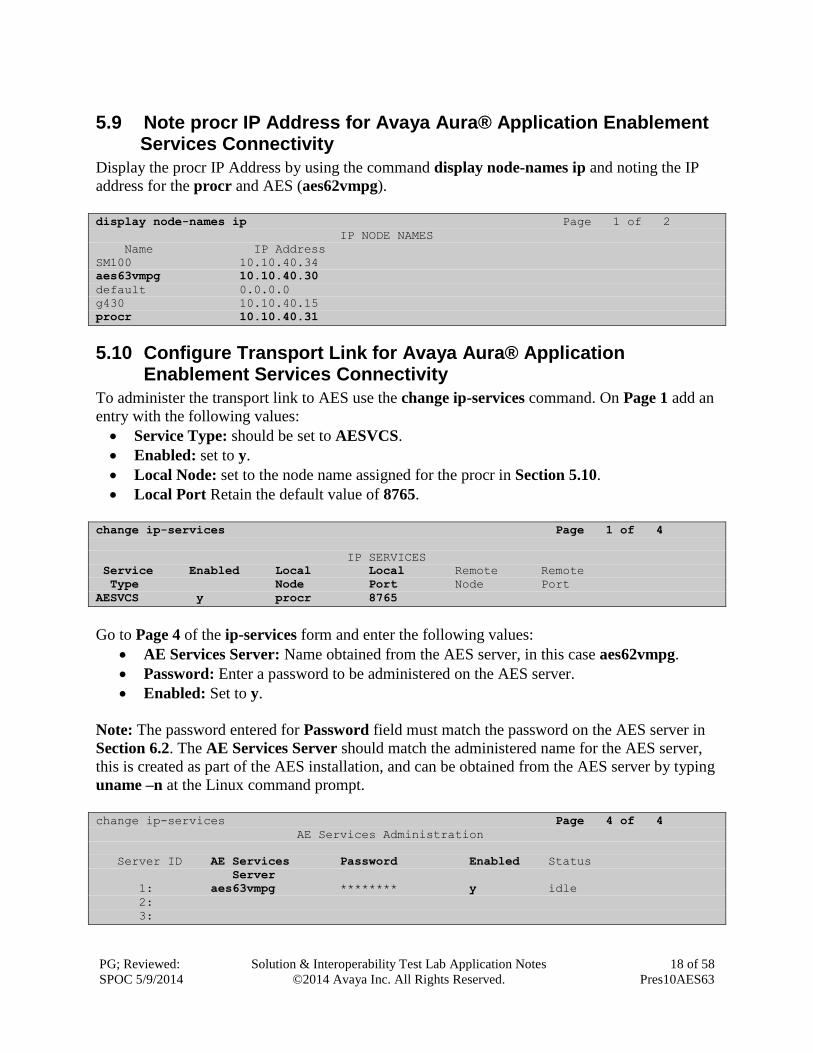
5.9 Note procr IP Address for Avaya Aura® Application Enablement Services Connectivity
Display the procr IP Address by using the command display node-names ip and noting the IP
address for the procr and AES (aes62vmpg).
display node-names ip Page 1 of 2
IP NODE NAMES
Name IP Address
SM100 10.10.40.34
aes63vmpg 10.10.40.30
default 0.0.0.0
g430 10.10.40.15
procr 10.10.40.31
5.10 Configure Transport Link for Avaya Aura® Application Enablement Services Connectivity
To administer the transport link to AES use the change ip-services command. On Page 1 add an
entry with the following values:
Service Type: should be set to AESVCS.
Enabled: set to y.
Local Node: set to the node name assigned for the procr in Section 5.10.
Local Port Retain the default value of 8765.
change ip-services Page 1 of 4
IP SERVICES
Service Enabled Local Local Remote Remote
Type Node Port Node Port
AESVCS y procr 8765
Go to Page 4 of the ip-services form and enter the following values:
AE Services Server: Name obtained from the AES server, in this case aes62vmpg.
Password: Enter a password to be administered on the AES server.
Enabled: Set to y.
Note: The password entered for Password field must match the password on the AES server in
Section 6.2. The AE Services Server should match the administered name for the AES server,
this is created as part of the AES installation, and can be obtained from the AES server by typing
uname –n at the Linux command prompt.
change ip-services Page 4 of 4
AE Services Administration
Server ID AE Services Password Enabled Status
Server
1: aes63vmpg ******** y idle
2:
3:
PG; Reviewed:
SPOC 5/9/2014
Solution & Interoperability Test Lab Application Notes
©2014 Avaya Inc. All Rights Reserved.
19 of 58
Pres10AES63
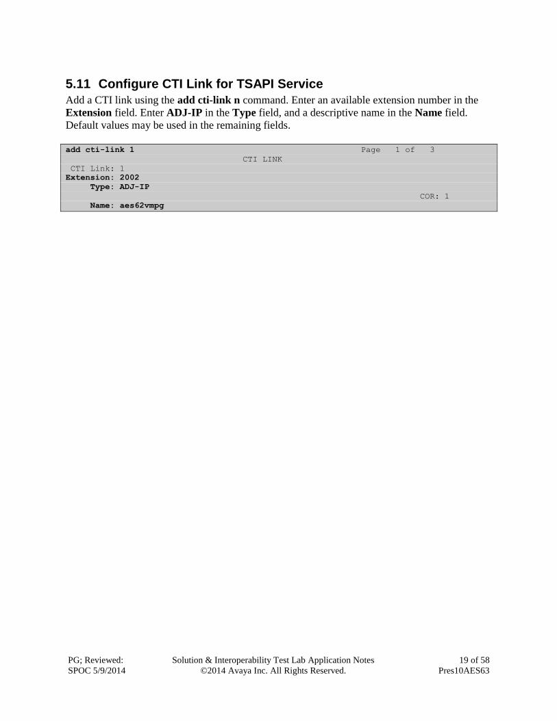
5.11 Configure CTI Link for TSAPI Service
Add a CTI link using the add cti-link n command. Enter an available extension number in the
Extension field. Enter ADJ-IP in the Type field, and a descriptive name in the Name field.
Default values may be used in the remaining fields.
add cti-link 1 Page 1 of 3
CTI LINK
CTI Link: 1
Extension: 2002
Type: ADJ-IP
COR: 1
Name: aes62vmpg

PG; Reviewed:
SPOC 5/9/2014
Solution & Interoperability Test Lab Application Notes
©2014 Avaya Inc. All Rights Reserved.
20 of 58
Pres10AES63
6 Configure Avaya Aura® Application Enablement Services Server
This section provides the procedures for configuring Application Enablement Services. The
procedures fall into the following areas:
Verify Licensing
Create Switch Connection
Administer TSAPI link
Create CTI User
Enable CTI Link User
Identify Tlinks
6.1 Verify Licensing
To access the maintenance console, enter https://<ip-addr> as the URL in an Internet browser,
where <ip-addr> is the active IP address of AES. The login screen is displayed, log in with the
appropriate credentials and then select the Login button.
PG; Reviewed:
SPOC 5/9/2014
Solution & Interoperability Test Lab Application Notes
©2014 Avaya Inc. All Rights Reserved.
21 of 58
Pres10AES63
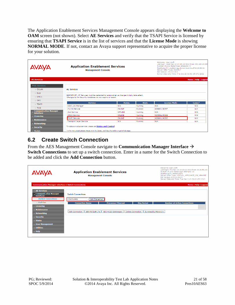
The Application Enablement Services Management Console appears displaying the Welcome to
OAM screen (not shown). Select AE Services and verify that the TSAPI Service is licensed by
ensuring that TSAPI Service is in the list of services and that the License Mode is showing
NORMAL MODE. If not, contact an Avaya support representative to acquire the proper license
for your solution.
6.2 Create Switch Connection
From the AES Management Console navigate to Communication Manager Interface
Switch Connections to set up a switch connection. Enter in a name for the Switch Connection to
be added and click the Add Connection button.
PG; Reviewed:
SPOC 5/9/2014
Solution & Interoperability Test Lab Application Notes
©2014 Avaya Inc. All Rights Reserved.
22 of 58
Pres10AES63
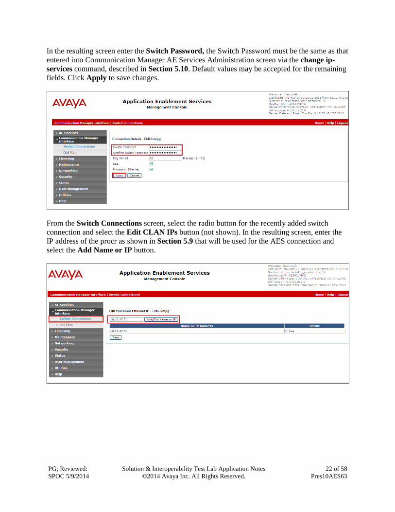
In the resulting screen enter the Switch Password, the Switch Password must be the same as that
entered into Communication Manager AE Services Administration screen via the change ip-
services command, described in Section 5.10. Default values may be accepted for the remaining
fields. Click Apply to save changes.
From the Switch Connections screen, select the radio button for the recently added switch
connection and select the Edit CLAN IPs button (not shown). In the resulting screen, enter the
IP address of the procr as shown in Section 5.9 that will be used for the AES connection and
select the Add Name or IP button.

PG; Reviewed:
SPOC 5/9/2014
Solution & Interoperability Test Lab Application Notes
©2014 Avaya Inc. All Rights Reserved.
23 of 58
Pres10AES63
6.3 Administer TSAPI link
From the Application Enablement Services Management Console, select AE Services TSAPI
TSAPI Links. Select Add Link button as shown in the screen below.
On the Add TSAPI Links screen, enter the following values:
Link: Use the drop-down list to select an unused link number.
Switch Connection: Choose the switch connection CM63VMPG, which has already
been configured in Section 6.2, from the drop-down list.
Switch CTI Link Number: Corresponding CTI link number configured in Section 5.11
which is 1.
ASAI Link Version: This can be left at the default value of 5.
Security: This can be left at the default value of both.
Once completed, select Apply Changes.
PG; Reviewed:
SPOC 5/9/2014
Solution & Interoperability Test Lab Application Notes
©2014 Avaya Inc. All Rights Reserved.
24 of 58
Pres10AES63
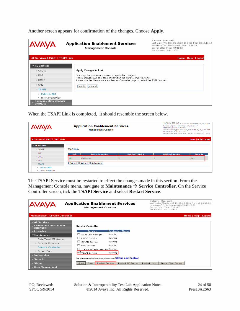
Another screen appears for confirmation of the changes. Choose Apply.
When the TSAPI Link is completed, it should resemble the screen below.
The TSAPI Service must be restarted to effect the changes made in this section. From the
Management Console menu, navigate to Maintenance Service Controller. On the Service
Controller screen, tick the TSAPI Service and select Restart Service.
PG; Reviewed:
SPOC 5/9/2014
Solution & Interoperability Test Lab Application Notes
©2014 Avaya Inc. All Rights Reserved.
25 of 58
Pres10AES63
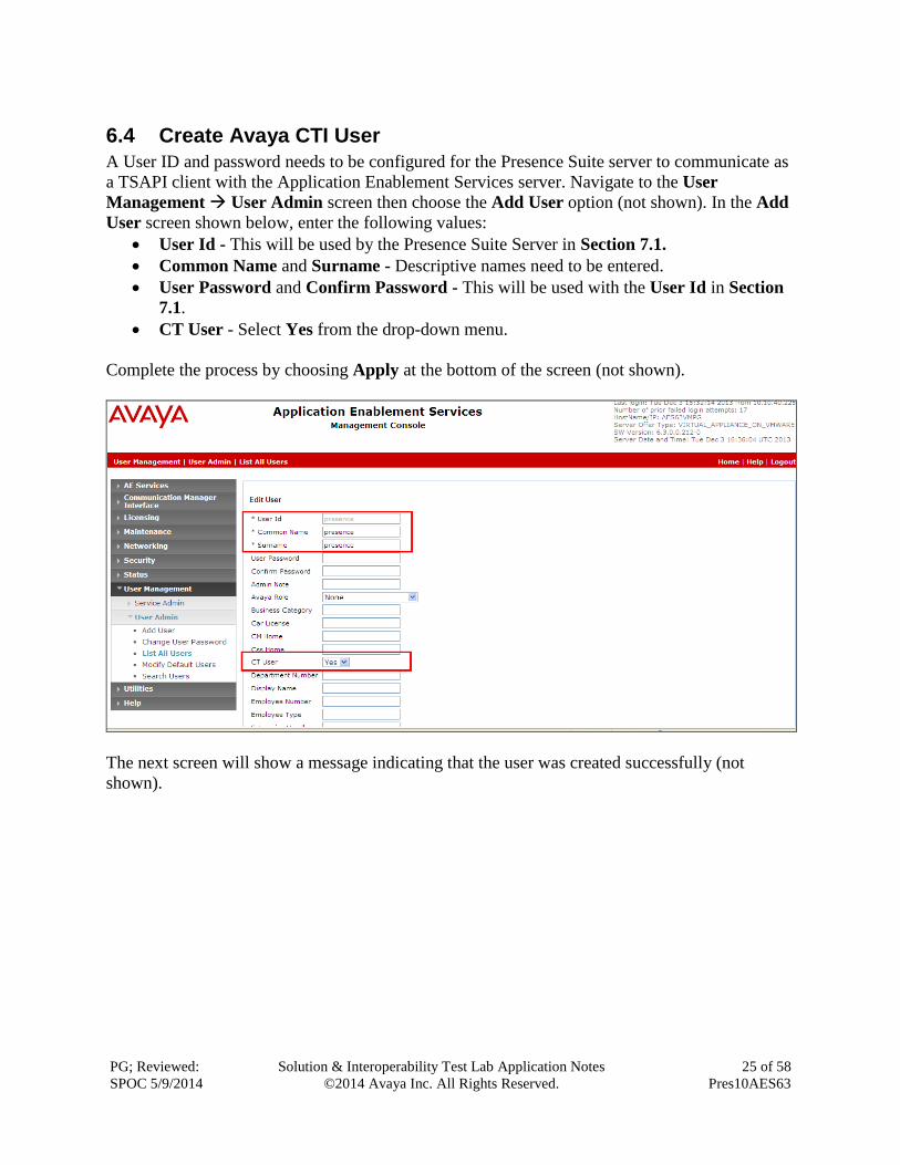
6.4 Create Avaya CTI User
A User ID and password needs to be configured for the Presence Suite server to communicate as
a TSAPI client with the Application Enablement Services server. Navigate to the User
Management User Admin screen then choose the Add User option (not shown). In the Add
User screen shown below, enter the following values:
User Id - This will be used by the Presence Suite Server in Section 7.1.
Common Name and Surname - Descriptive names need to be entered.
User Password and Confirm Password - This will be used with the User Id in Section
7.1.
CT User - Select Yes from the drop-down menu.
Complete the process by choosing Apply at the bottom of the screen (not shown).
The next screen will show a message indicating that the user was created successfully (not
shown).
PG; Reviewed:
SPOC 5/9/2014
Solution & Interoperability Test Lab Application Notes
©2014 Avaya Inc. All Rights Reserved.
26 of 58
Pres10AES63
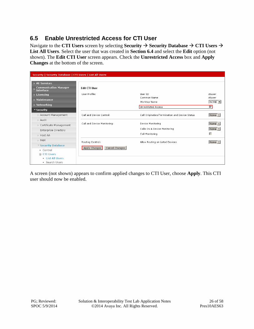
6.5 Enable Unrestricted Access for CTI User
Navigate to the CTI Users screen by selecting Security Security Database CTI Users
List All Users. Select the user that was created in Section 6.4 and select the Edit option (not
shown). The Edit CTI User screen appears. Check the Unrestricted Access box and Apply
Changes at the bottom of the screen.
A screen (not shown) appears to confirm applied changes to CTI User, choose Apply. This CTI
user should now be enabled.
PG; Reviewed:
SPOC 5/9/2014
Solution & Interoperability Test Lab Application Notes
©2014 Avaya Inc. All Rights Reserved.
27 of 58
Pres10AES63
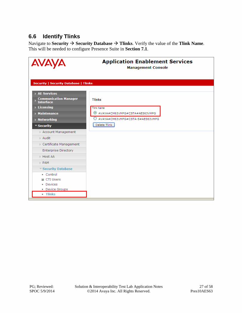
6.6 Identify Tlinks
Navigate to Security Security Database Tlinks. Verify the value of the Tlink Name.
This will be needed to configure Presence Suite in Section 7.1.
PG; Reviewed:
SPOC 5/9/2014
Solution & Interoperability Test Lab Application Notes
©2014 Avaya Inc. All Rights Reserved.
28 of 58
Pres10AES63
7 Configure the Presence Suite Server The Presence Suite includes the Presence Server, Presence Mail Interactions Server, Presence
Web Interactions Server, Presence Administrator, Presence Supervisor, and Presence Agent. The
Presence Server and the Oracle database were pre-installed on the same machine for convenience
during the compliance testing. The Presence server was configured and provided by Presence
Technology. An outline of the configuration relevant to the Avaya solution integration is detailed
below.
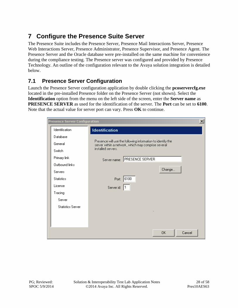
7.1 Presence Server Configuration
Launch the Presence Server configuration application by double clicking the pcoservercfg.exe
located in the pre-installed Presence folder on the Presence Server (not shown). Select the
Identification option from the menu on the left side of the screen, enter the Server name as
PRESENCE SERVER as used for the identification of the server. The Port can be set to 6100.
Note that the actual value for server port can vary. Press OK to continue.

PG; Reviewed:
SPOC 5/9/2014
Solution & Interoperability Test Lab Application Notes
©2014 Avaya Inc. All Rights Reserved.
29 of 58
Pres10AES63
Select General from the menu on the left side of the screen. If desired, the Maintenance
configuration values can be altered here, for the compliance test the default values were retained.
PG; Reviewed:
SPOC 5/9/2014
Solution & Interoperability Test Lab Application Notes
©2014 Avaya Inc. All Rights Reserved.
30 of 58
Pres10AES63
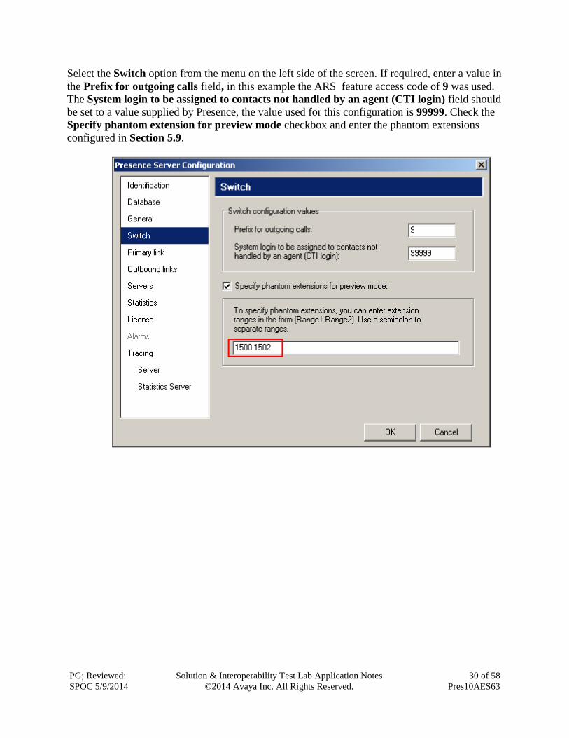
Select the Switch option from the menu on the left side of the screen. If required, enter a value in
the Prefix for outgoing calls field, in this example the ARS feature access code of 9 was used.
The System login to be assigned to contacts not handled by an agent (CTI login) field should
be set to a value supplied by Presence, the value used for this configuration is 99999. Check the
Specify phantom extension for preview mode checkbox and enter the phantom extensions
configured in Section 5.9.
PG; Reviewed:
SPOC 5/9/2014
Solution & Interoperability Test Lab Application Notes
©2014 Avaya Inc. All Rights Reserved.
31 of 58
Pres10AES63
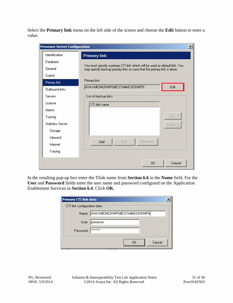
Select the Primary link menu on the left side of the screen and choose the Edit button to enter a
value.
In the resulting pop-up box enter the Tlink name from Section 6.6 in the Name field. For the
User and Password fields enter the user name and password configured on the Application
Enablement Services in Section 6.4. Click OK.
PG; Reviewed:
SPOC 5/9/2014
Solution & Interoperability Test Lab Application Notes
©2014 Avaya Inc. All Rights Reserved.
32 of 58
Pres10AES63
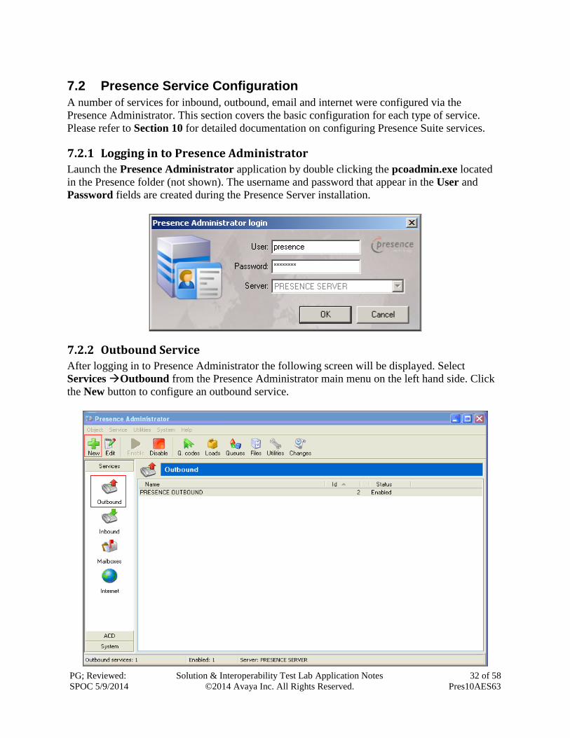
7.2 Presence Service Configuration
A number of services for inbound, outbound, email and internet were configured via the
Presence Administrator. This section covers the basic configuration for each type of service.
Please refer to Section 10 for detailed documentation on configuring Presence Suite services.
7.2.1 Logging in to Presence Administrator
Launch the Presence Administrator application by double clicking the pcoadmin.exe located
in the Presence folder (not shown). The username and password that appear in the User and
Password fields are created during the Presence Server installation.
7.2.2 Outbound Service
After logging in to Presence Administrator the following screen will be displayed. Select
Services Outbound from the Presence Administrator main menu on the left hand side. Click
the New button to configure an outbound service.
PG; Reviewed:
SPOC 5/9/2014
Solution & Interoperability Test Lab Application Notes
©2014 Avaya Inc. All Rights Reserved.
33 of 58
Pres10AES63
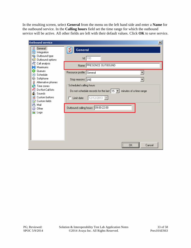
In the resulting screen, select General from the menu on the left hand side and enter a Name for
the outbound service. In the Calling hours field set the time range for which the outbound
service will be active. All other fields are left with their default values. Click OK to save service.
PG; Reviewed:
SPOC 5/9/2014
Solution & Interoperability Test Lab Application Notes
©2014 Avaya Inc. All Rights Reserved.
34 of 58
Pres10AES63
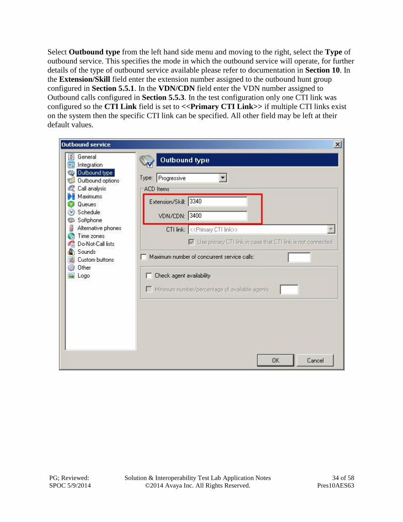
Select Outbound type from the left hand side menu and moving to the right, select the Type of
outbound service. This specifies the mode in which the outbound service will operate, for further
details of the type of outbound service available please refer to documentation in Section 10. In
the Extension/Skill field enter the extension number assigned to the outbound hunt group
configured in Section 5.5.1. In the VDN/CDN field enter the VDN number assigned to
Outbound calls configured in Section 5.5.3. In the test configuration only one CTI link was
configured so the CTI Link field is set to <<Primary CTI Link>> if multiple CTI links exist
on the system then the specific CTI link can be specified. All other field may be left at their
default values.
PG; Reviewed:
SPOC 5/9/2014
Solution & Interoperability Test Lab Application Notes
©2014 Avaya Inc. All Rights Reserved.
35 of 58
Pres10AES63
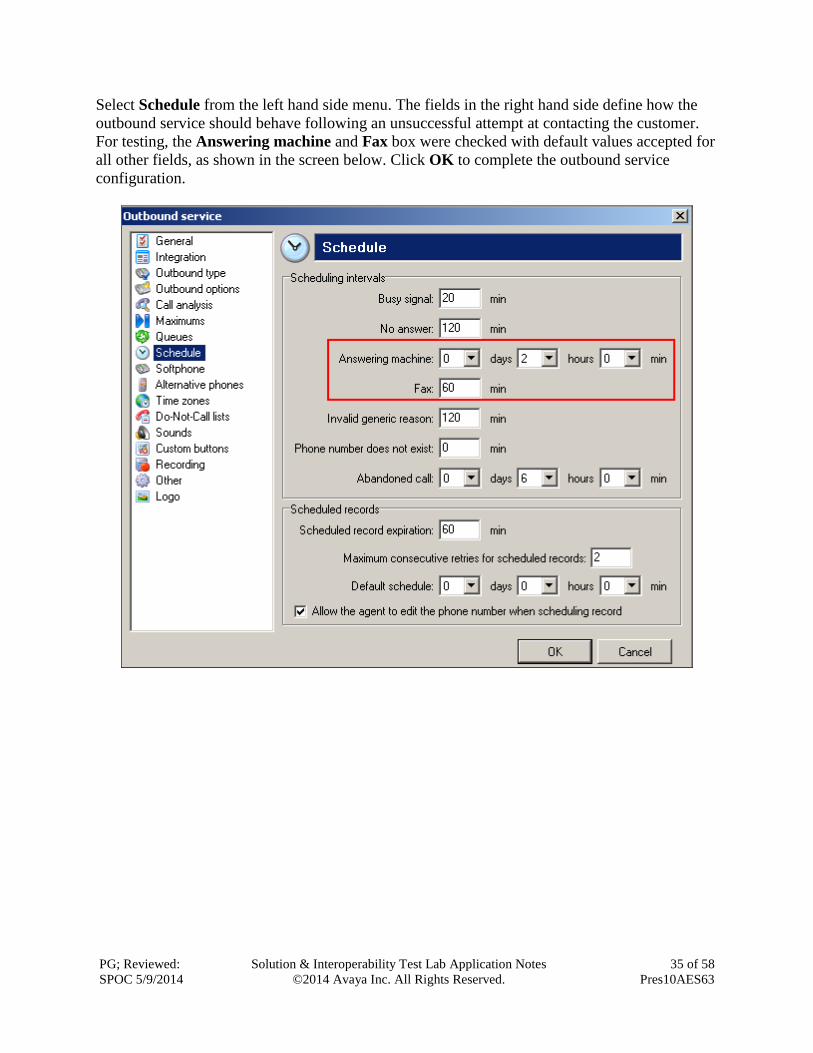
Select Schedule from the left hand side menu. The fields in the right hand side define how the
outbound service should behave following an unsuccessful attempt at contacting the customer.
For testing, the Answering machine and Fax box were checked with default values accepted for
all other fields, as shown in the screen below. Click OK to complete the outbound service
configuration.

PG; Reviewed:
SPOC 5/9/2014
Solution & Interoperability Test Lab Application Notes
©2014 Avaya Inc. All Rights Reserved.
36 of 58
Pres10AES63
7.2.3 Inbound Service
To configure an inbound service, from the left hand side select Services Inbound from the
Presence Administrator main menu. Click the New button.

PG; Reviewed:
SPOC 5/9/2014
Solution & Interoperability Test Lab Application Notes
©2014 Avaya Inc. All Rights Reserved.
37 of 58
Pres10AES63
In the resulting screen, select General from the menu on the left hand side and enter a Name for
the inbound service. All other fields are left with their default values.

PG; Reviewed:
SPOC 5/9/2014
Solution & Interoperability Test Lab Application Notes
©2014 Avaya Inc. All Rights Reserved.
38 of 58
Pres10AES63
Select ACD from the left hand side menu and moving to the right, under the heading Skills,
enter the skill group extensions configured in Section 5.5.1 that will handle inbound calls in the
untitled box (this includes email and web chat call types) and click Add. The skill group
extensions will then appear to the left in the Extension/Skill box. Under the heading VDN/CDN
enter the VDN configured in Section 5.5.3 that will handle inbound calls in the untitled box and
click Add. The VDN will then appear to the left in the VDN/CDN box.
PG; Reviewed:
SPOC 5/9/2014
Solution & Interoperability Test Lab Application Notes
©2014 Avaya Inc. All Rights Reserved.
39 of 58
Pres10AES63
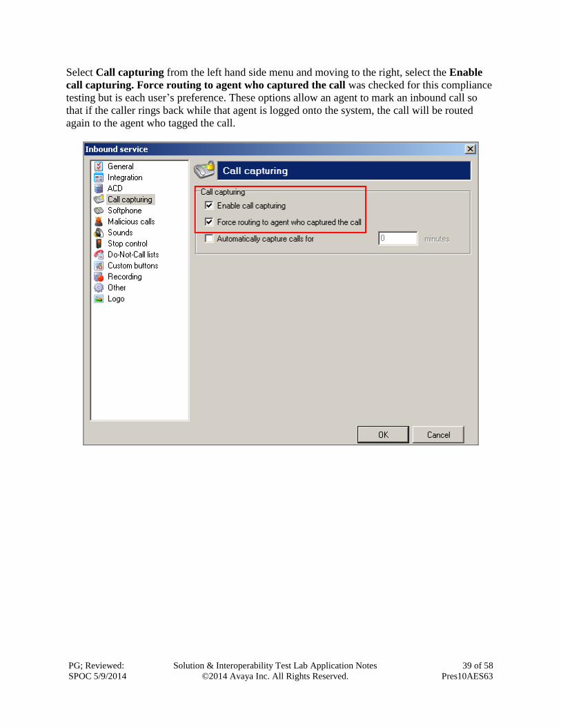
Select Call capturing from the left hand side menu and moving to the right, select the Enable
call capturing. Force routing to agent who captured the call was checked for this compliance
testing but is each user’s preference. These options allow an agent to mark an inbound call so
that if the caller rings back while that agent is logged onto the system, the call will be routed
again to the agent who tagged the call.
PG; Reviewed:
SPOC 5/9/2014
Solution & Interoperability Test Lab Application Notes
©2014 Avaya Inc. All Rights Reserved.
40 of 58
Pres10AES63
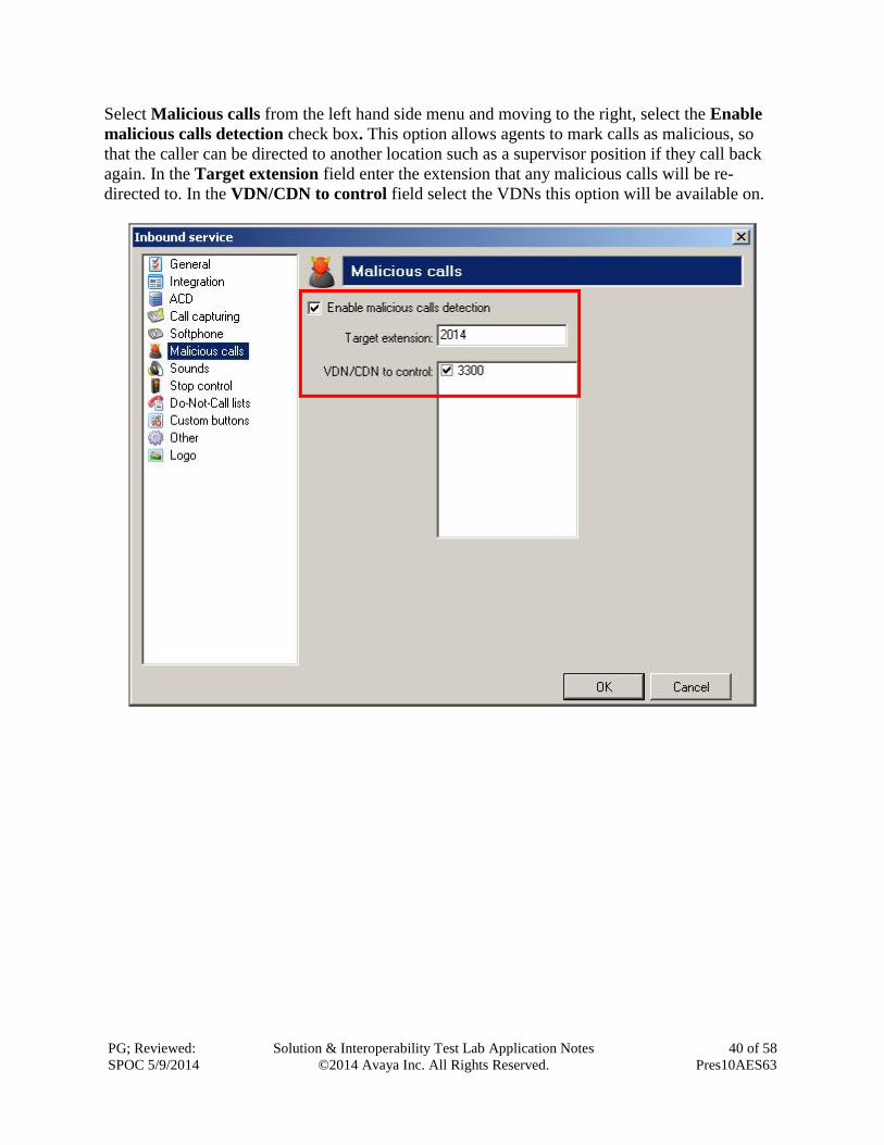
Select Malicious calls from the left hand side menu and moving to the right, select the Enable
malicious calls detection check box. This option allows agents to mark calls as malicious, so
that the caller can be directed to another location such as a supervisor position if they call back
again. In the Target extension field enter the extension that any malicious calls will be re-
directed to. In the VDN/CDN to control field select the VDNs this option will be available on.
PG; Reviewed:
SPOC 5/9/2014
Solution & Interoperability Test Lab Application Notes
©2014 Avaya Inc. All Rights Reserved.
41 of 58
Pres10AES63
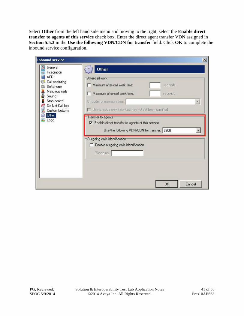
Select Other from the left hand side menu and moving to the right, select the Enable direct
transfer to agents of this service check box. Enter the direct agent transfer VDN assigned in
Section 5.5.3 in the Use the following VDN/CDN for transfer field. Click OK to complete the
inbound service configuration.

PG; Reviewed:
SPOC 5/9/2014
Solution & Interoperability Test Lab Application Notes
©2014 Avaya Inc. All Rights Reserved.
42 of 58
Pres10AES63
7.2.4 Email Service
To configure an email service, from the left hand side select Services Mailboxes from the
Presence Administrator main menu. Click the New button.

PG; Reviewed:
SPOC 5/9/2014
Solution & Interoperability Test Lab Application Notes
©2014 Avaya Inc. All Rights Reserved.
43 of 58
Pres10AES63
In the resulting screen, select General from the menu on the left hand side and enter a Name for
the email service. Referring to Table 2, Section 5.5, under the heading VDN/CDN in the
General field enter the VDN assigned for email and enter the VDN assigned for suspended
emails in the Suspended field. The association of a VDN to an incoming email allows the
reporting of incoming emails simply because the reporting of VDN’s is standard on
Communication Manager.

PG; Reviewed:
SPOC 5/9/2014
Solution & Interoperability Test Lab Application Notes
©2014 Avaya Inc. All Rights Reserved.
44 of 58
Pres10AES63
Select Incoming mail from the left hand side menu. This window allows administrator to
specify the POP3 server and account from which to download incoming mails. In the Server
field enter the POP3 mail server address.For the interoperability testing this was the same IP
address as the Presence Server. The default POP3 port of 110 is entered into the Port field.
Under the Incoming mail account heading enter the Account name, Password and E-mail
address associated with the POP3 mail account.
PG; Reviewed:
SPOC 5/9/2014
Solution & Interoperability Test Lab Application Notes
©2014 Avaya Inc. All Rights Reserved.
45 of 58
Pres10AES63
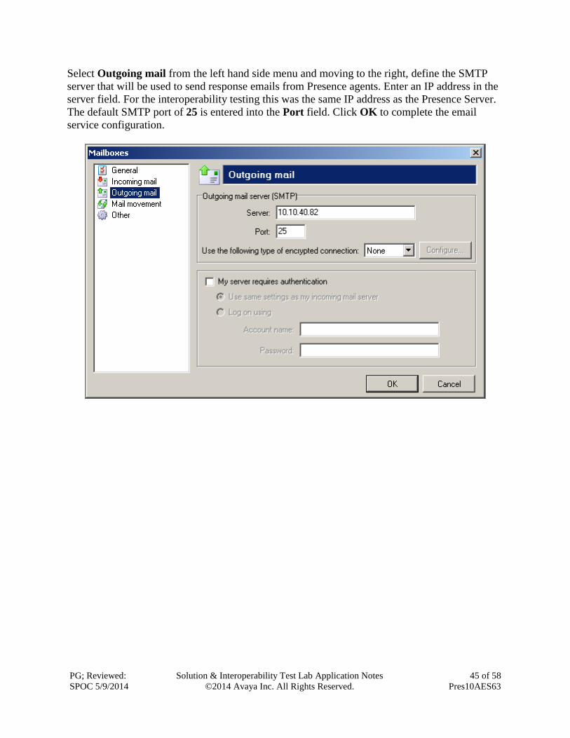
Select Outgoing mail from the left hand side menu and moving to the right, define the SMTP
server that will be used to send response emails from Presence agents. Enter an IP address in the
server field. For the interoperability testing this was the same IP address as the Presence Server.
The default SMTP port of 25 is entered into the Port field. Click OK to complete the email
service configuration.

PG; Reviewed:
SPOC 5/9/2014
Solution & Interoperability Test Lab Application Notes
©2014 Avaya Inc. All Rights Reserved.
46 of 58
Pres10AES63
7.2.5 Web Chat / Web Call Back
To configure a web service, from the left hand side select Services Internet from the
Presence Administrator main menu. Click the New button.

PG; Reviewed:
SPOC 5/9/2014
Solution & Interoperability Test Lab Application Notes
©2014 Avaya Inc. All Rights Reserved.
47 of 58
Pres10AES63
In the resulting screen, select General from the menu on the left hand side and enter a Name for
the web service. Under the URL heading three URLs are defined:
The Waiting URL is the URL that is presented to the customer if no agents are available.
The Goodbye URL is the URL that is presented to the customer when the web callback
or web chat session ends.
The Service disabled URL is the URL that is presented to the customer if the service has
been disabled for any reason.
Note: These URL options were added by the Presence engineers.

PG; Reviewed:
SPOC 5/9/2014
Solution & Interoperability Test Lab Application Notes
©2014 Avaya Inc. All Rights Reserved.
48 of 58
Pres10AES63
Select Session type in the left hand pane, the Chat service and Callback service check boxes
should be selected and the relevant VDN for each entered into the VDN/CDN field, click OK
when done.

PG; Reviewed:
SPOC 5/9/2014
Solution & Interoperability Test Lab Application Notes
©2014 Avaya Inc. All Rights Reserved.
49 of 58
Pres10AES63
7.2.6 Add ACD Agent Logins
To add the agent logins administered on Communication Manager for use by Presence Suite,
from the left hand pane of the Presence Administrator main menu select ACD Logins and
click the Login button.
PG; Reviewed:
SPOC 5/9/2014
Solution & Interoperability Test Lab Application Notes
©2014 Avaya Inc. All Rights Reserved.
50 of 58
Pres10AES63
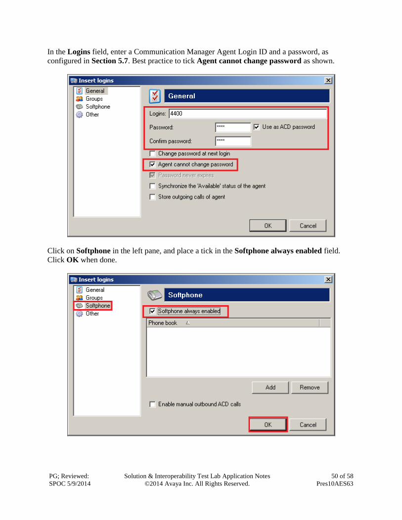
In the Logins field, enter a Communication Manager Agent Login ID and a password, as
configured in Section 5.7. Best practice to tick Agent cannot change password as shown.
Click on Softphone in the left pane, and place a tick in the Softphone always enabled field.
Click OK when done.

PG; Reviewed:
SPOC 5/9/2014
Solution & Interoperability Test Lab Application Notes
©2014 Avaya Inc. All Rights Reserved.
51 of 58
Pres10AES63
7.3 Presence Agent Configuration
The following steps are carried out on the Presence Suite Agent PC. Prior to installing the
Presence agent, ensure that the DBExpress driver (dbexpoda.dll) is located in the
C:\Windows\System32 directory. The DBExpress driver allows the agent application to
communicate with the Oracle database. Installing this driver eliminates the need to install the
Oracle client. Launch the Presence agent configuration application by double clicking the
pcoagentcfg.exe located in the C: Presence folder. Enter the Presence Server IP: address as
10.10.16.68. The Presence Server port can be left as the default value of 6100. Enter the
extension of the agent that will be using this workstation in the Agent station field. Check the
Hang up calls before logging in check box. In the field Use configuration for choose Machine
from the drop down menu. Click OK. This step is needed for each agent configured; only the
agent station field will vary.

PG; Reviewed:
SPOC 5/9/2014
Solution & Interoperability Test Lab Application Notes
©2014 Avaya Inc. All Rights Reserved.
52 of 58
Pres10AES63
7.3.1 Logging in Presence Agent
Launch the Presence agent configuration application by double clicking the pcoagent.exe
located in the Presence folder (not shown). Enter the agent Login and Password configured in
Section 5.7 and click on OK.
In the next screen, click on the Services button in the task bar. The service set up for the agent
will be displayed.
PG; Reviewed:
SPOC 5/9/2014
Solution & Interoperability Test Lab Application Notes
©2014 Avaya Inc. All Rights Reserved.
53 of 58
Pres10AES63
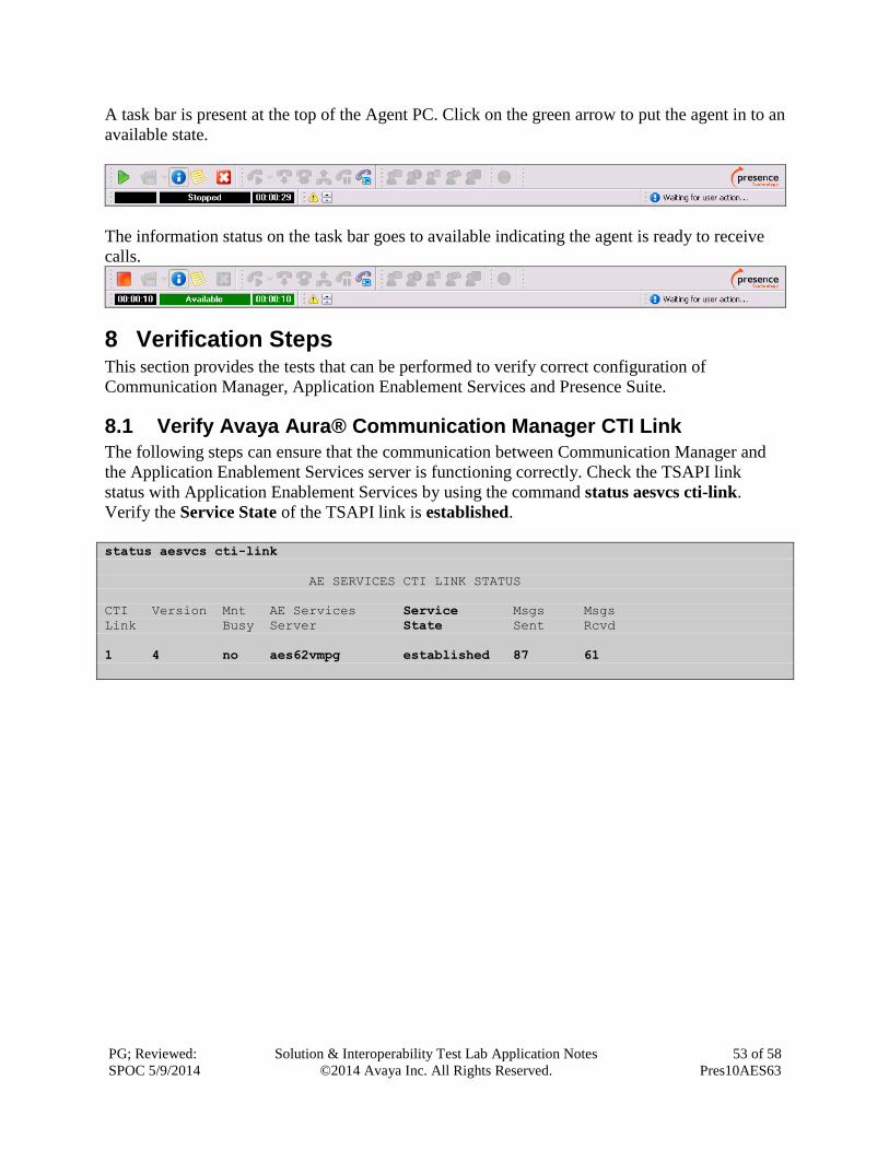
A task bar is present at the top of the Agent PC. Click on the green arrow to put the agent in to an
available state.
The information status on the task bar goes to available indicating the agent is ready to receive
calls.
8 Verification Steps This section provides the tests that can be performed to verify correct configuration of
Communication Manager, Application Enablement Services and Presence Suite.
8.1 Verify Avaya Aura® Communication Manager CTI Link
The following steps can ensure that the communication between Communication Manager and
the Application Enablement Services server is functioning correctly. Check the TSAPI link
status with Application Enablement Services by using the command status aesvcs cti-link.
Verify the Service State of the TSAPI link is established.
status aesvcs cti-link
AE SERVICES CTI LINK STATUS
CTI Version Mnt AE Services Service Msgs Msgs
Link Busy Server State Sent Rcvd
1 4 no aes62vmpg established 87 61
PG; Reviewed:
SPOC 5/9/2014
Solution & Interoperability Test Lab Application Notes
©2014 Avaya Inc. All Rights Reserved.
54 of 58
Pres10AES63
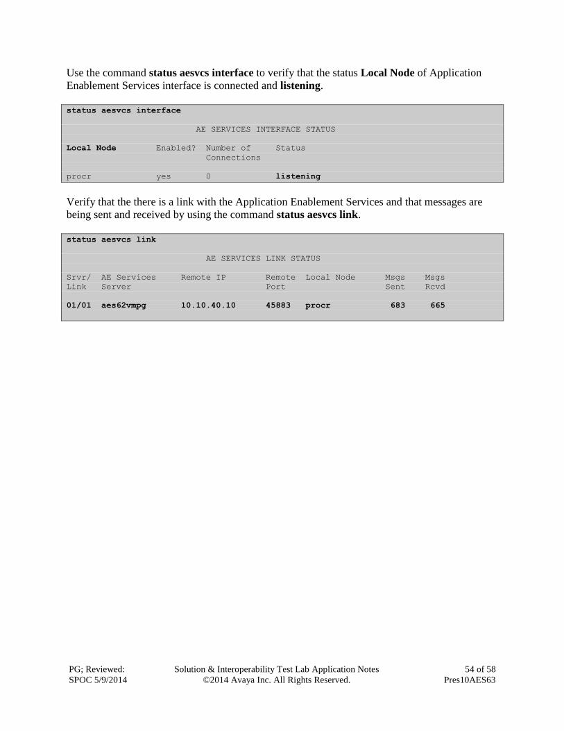
Use the command status aesvcs interface to verify that the status Local Node of Application
Enablement Services interface is connected and listening.
status aesvcs interface
AE SERVICES INTERFACE STATUS
Local Node Enabled? Number of Status
Connections
procr yes 0 listening
Verify that the there is a link with the Application Enablement Services and that messages are
being sent and received by using the command status aesvcs link.
status aesvcs link
AE SERVICES LINK STATUS
Srvr/ AE Services Remote IP Remote Local Node Msgs Msgs
Link Server Port Sent Rcvd
01/01 aes62vmpg 10.10.40.10 45883 procr 683 665
PG; Reviewed:
SPOC 5/9/2014
Solution & Interoperability Test Lab Application Notes
©2014 Avaya Inc. All Rights Reserved.
55 of 58
Pres10AES63
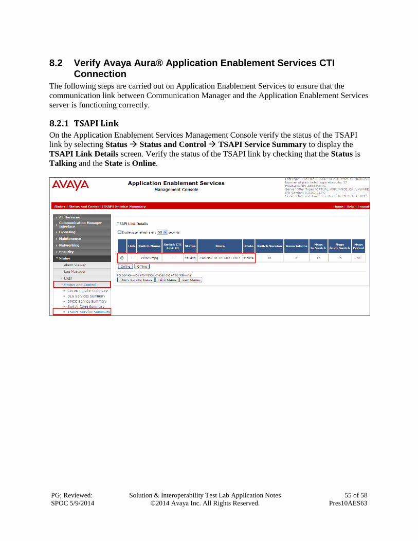
8.2 Verify Avaya Aura® Application Enablement Services CTI Connection
The following steps are carried out on Application Enablement Services to ensure that the
communication link between Communication Manager and the Application Enablement Services
server is functioning correctly.
8.2.1 TSAPI Link
On the Application Enablement Services Management Console verify the status of the TSAPI
link by selecting Status Status and Control TSAPI Service Summary to display the
TSAPI Link Details screen. Verify the status of the TSAPI link by checking that the Status is
Talking and the State is Online.

PG; Reviewed:
SPOC 5/9/2014
Solution & Interoperability Test Lab Application Notes
©2014 Avaya Inc. All Rights Reserved.
56 of 58
Pres10AES63
8.3 Verify Presence Suite CTI Connection
One of the available methods to confirm correct startup is a startup log which can be accessed
from Presence Management Console. Navigate to C: Presence pmconsole.exe (not
shown). A startup log commences when the Presence Server is trying to load and connect to the
Application Enablement Services server. Click on the item named [email protected]:6800 in
the PCP Server Connections pane of the Management Console. To open the startup event log,
double click Show startup event log in the Actions pane.
Verify successful CTI connection and service startup.
PG; Reviewed:
SPOC 5/9/2014
Solution & Interoperability Test Lab Application Notes
©2014 Avaya Inc. All Rights Reserved.
57 of 58
Pres10AES63
9 Conclusion These Application Notes describe the configuration steps required for Presence Suite R10.0 to
successfully interoperate with Avaya Aura® Communication Manager R6.2 using Avaya Aura®
Application Enablement Services R6.2. All feature functionality and serviceability test cases
were completed successfully with observations noted in Section 2.2.
10 Additional References This section references the Avaya and Presence Suite product documentation that are relevant to
these Application Notes.
Product documentation for Avaya products may be found at http://support.avaya.com.
[1] Administering Avaya Aura® Communication Manager, Document ID 03-300509
[2] Avaya Aura® Communication Manager Feature Description and Implementation,
Document ID 555-245-205
[3] Avaya Aura® Application Enablement Services Administration and Maintenance Guide Release 6.2
The following documentation is available on request from Presence: www.presenceco.com
[4] ACD Sys Presence Administrator Manual Presence Suite, V10.0
[5] Presence Installation Guides Presence Software, V10.0
[6] PBX/ACD Requirements Presence Software, V10.0
PG; Reviewed:
SPOC 5/9/2014
Solution & Interoperability Test Lab Application Notes
©2014 Avaya Inc. All Rights Reserved.
58 of 58
Pres10AES63
©2014 Avaya Inc. All Rights Reserved. Avaya and the Avaya Logo are trademarks of Avaya Inc. All trademarks identified by ® and ™
are registered trademarks or trademarks, respectively, of Avaya Inc. All other trademarks are
the property of their respective owners. The information provided in these Application Notes is
subject to change without notice. The configurations, technical data, and recommendations
provided in these Application Notes are believed to be accurate and dependable, but are
presented without express or implied warranty. Users are responsible for their application of
any products specified in these Application Notes.
Please e-mail any questions or comments pertaining to these Application Notes along with the
full title name and filename, located in the lower right corner, directly to the Avaya DevConnect
Program at [email protected].