Embed Size (px)
Citation preview
APPLICATION OF A PRECAST CONCRETE BARRIER ADJACENT TO A STEEP 1
ROADSIDE SLOPE 2 3
Nauman M. Sheikh 4 Texas Transportation Institute 5
Texas A&M University System 6
MS-3135 7
College Station, TX 77843-3135 8
Phone: (979) 845-8955 9
Fax: (979) 845-6107 10
12
Roger P. Bligh 13 Texas Transportation Institute 14
Texas A&M University System 15
MS-3135 16
College Station, TX 77843-3135 17
Phone: (979) 845-4377 18
Fax: (979) 845-6107 19
21
Richard B. Albin 22 Federal Highway Administration 23
12300 West Dakota Avenue, Suite 340 24
Lakewood, CO 80228 25
Phone: (720) 963-3266 26
28
Dave Olson 29 Washington State Department of Transportation 30
PO Box 47329 31
Olympia, WA 98504-7329 32
Phone: (360) 705-7952 33
35
36
Submission date: November 15, 2009 37
Word count: 7,140 (5,140 words + 1 table + 7 figures) 38
39
TRB 2010 Annual Meeting CD-ROM Paper revised from original submittal.

ABSTRACT 40 41
When concrete barriers are installed adjacent to drop-offs or steep roadside slopes such as 42
1.5H:1V, a cast-in-place concrete moment slab is usually attached to the base of the barrier to 43
resist lateral and overturning forces during vehicle impact. Cast-in-place construction can require 44
more time on site to build forms, pour the concrete, and allow for curing. This results in an 45
increase in disruption to traffic and more exposure for construction workers. Furthermore, the 46
installation of a moment slab is very costly and requires an additional construction phase to build 47
the slab. Since the slab is normally under the shoulder and possibly the lanes, the disruption of 48
traffic flow is increased. This paper presents a new application of a precast 42-inch tall single 49
slope concrete barrier for use in front of steep slopes, without requiring a moment slab. The 50
lateral movement of the barrier is restricted by embedding it in soil. This design also reduces the 51
embankment behind the barrier to two feet. The embedded barrier application was successfully 52
evaluated under Manual for Assessing Safety Hardware test level 3 criteria. The permanent 53
deflection of the barrier was 5.5 inches. The use of the embedded concrete barrier in lieu of the 54
typically installed barrier with a moment slab is expected to result in cost savings of 55
approximately $300 per linear foot and reduced time to construct. 56
57
TRB 2010 Annual Meeting CD-ROM Paper revised from original submittal.

58
INTRODUCTION 59 Roadside barriers are used to shield motorists from hazards located off the traveled way. 60
A naturally occurring hazard common in mountainous regions and constrained environments is a 61
steep, non-traversable roadside slope. Available right-of-way along highways in these regions is 62
often restricted. Thus, it is desirable to place the barrier as close to the slope break point as 63
possible in order to maximize available space for travel lanes and shoulders. 64
65
There are various types of roadside barriers that have met current crash test criteria and 66
been accepted for use on the National Highway System. These barriers are generally categorized 67
as flexible, semi-rigid, or rigid depending on their deflection characteristics. While flexible 68
systems typically have lower injury probability due to their more forgiving nature, their use is 69
often limited as a result of the space required to accommodate their high design deflections. 70
Thus, when installing a barrier in close proximity to a steep, non-traversable slope, a semi-rigid 71
or rigid system is often preferred. 72
73
Semi-rigid barriers include strong-post, corrugated beam (e.g. W-beam, thrie beam) 74
guardrail systems. While variations of these systems have been successfully tested in close 75
proximity to steep slopes (1), their installation can be difficult due to deep embedment depths of 76
the posts and/or smaller post spacing that are characteristic of these designs. Further, the 77
maintenance and repair of impact damage required for these semi-rigid systems can pose 78
additional risk to workers due to the close proximity of both traffic and the hazardous slope 79
condition. 80
81
Use of a more rigid concrete barrier system can mitigate the cost and risk of maintenance 82
and repair. They are often selected where space is constrained and only a small amount of 83
deflection is allowable. These systems are also used where there is a frequent occurrence of 84
impacts and a reduced maintenance is desired. 85
86
Concrete barriers can be cast in place or installed in precast sections. Cast-in-place 87
construction can require more time on site to build forms, pour the concrete, and allow for 88
curing. This results in an increase in disruption to traffic and more exposure for construction 89
workers. Concrete barriers are typically designed with the barrier embedded in the ground, keyed 90
in the pavement, or with some type of foundation to make them rigid. This configuration is fairly 91
typical for median applications. However, there has not been any testing performed for these 92
keyed or embedded barriers in a configuration where the barrier is installed on the roadside 93
adjacent to a steep slope. Some of the concrete barriers designs have used vertical steel pins that 94
pass through holes in the barrier and continue some distance into the ground to restrict lateral 95
barrier movement. The barriers in these designs were tested while placed on asphalt or concrete 96
pavements, which helped reduce deflections during vehicle impacts. Such designs however are 97
typically used in temporary barrier applications. 98
99
In the absence of a restraining mechanism, designers recommend several feet of 100
embankment behind a concrete barrier to develop the required strength and barrier stability 101
during an impact. When this space is not available, current design practice requires the use of a 102
below grade moment slab similar to the one depicted in Figure 1. However, the installation of a 103
TRB 2010 Annual Meeting CD-ROM Paper revised from original submittal.

cast-in-place moment slab (which includes excavation, forming, concrete placement, and 104
compaction of soil backfill) can be very expensive and requires an additional construction phase 105
to build the slab. Since the slab is normally under the shoulder and possibly the lanes, the 106
disruption of traffic flow is increased. There is a need for a cost-effective barrier system for use 107
adjacent to steep slopes that has limited deflection and low maintenance and repair needs. 108
109 Figure 1: Single slope barrier with a moment slab. 110
111
OBJECTIVE 112 The objective of the research presented in this paper was to develop a cost-effective, 113
concrete barrier system that can be placed in front of slopes as steep as 1.5H:1V. The design 114
constraints excluded use of a moment slab and permitted no more than 2 ft of offset from the 115
slope break point. The barrier system was required to meet the impact performance criteria 116
recommended in the AASHTO Manual for Assessing Safety Hardware (MASH) (2), and have a 117
deflection of less than 12 inches for a design impact. If embedment of the barrier was required, 118
the depth of embedment was limited to 10 inches. 119
120
DESIGN AND ANALYSIS 121 The design and analysis was performed using the single or constant slope barrier profile. 122
This profile was used due to the ease of embedment if needed. A standard single slope barrier is 123
42 inches tall and can be embedded 10 inches without needing a change in its profile. At a 10 124
inch embedment, the barrier would still have a height of 32 inches above the ground, which is 125
typical of most other concrete barriers such as the New Jersey and F-shape barriers. The barrier 126
used in this research was precast with a 20-ft segment length. Adjacent barrier segments were 127
connected using the grouted rebar-grid connection. This connection type and segment length is 128
typically used by the participating pooled fund states. 129
130
Evaluation of the free-standing barrier 131 In 1989, Texas Transportation Institute performed crash testing of the single-slope barrier 132
with the grouted rebar-grid connection, but the barrier was keyed into an asphalt layer which 133
prevented its lateral movement. Another test was performed under the same project with the free-134
standing single slope barrier, but the rebar grid connection was not grouted (3). To date, no 135
testing has been performed with the single slope barrier using the grouted rebar-grid slot 136
TRB 2010 Annual Meeting CD-ROM Paper revised from original submittal.
connection in a free-standing condition. As a first step, the researchers evaluated the 137
performance of the free-standing single slope barrier. The objective of this evaluation was to 138
determine if this connection provided sufficient strength to transfer moments between adjacent 139
barrier segments and cause them to deflect as a single body during vehicle impact, without 140
significant rotation at the joints. If this could be achieved, it was believed that the impacting 141
vehicle can be contained and redirected without significant barrier deflection simply using the 142
weight of the concrete barrier. This would have also rendered easiest solution to the design 143
problem and allowed maximum flexibility in the use of the barrier. 144
145
To evaluate the performance of the free-standing single slope barrier with grouted rebar-146
grid connection, the researchers first determined the response of a single barrier connection using 147
surrogate bogie vehicle testing. Two 42-inch tall and 20-ft long single-slope barrier segments 148
were connected using the grouted rebar-grid connection. The outside ends of the barrier 149
segments were constrained from moving laterally by a 5 inch diameter pipe that was anchored to 150
the concrete pavement as shown in Figure 2-a. A 5000-lb bogie vehicle impacted the barrier at 151
the connection with an impact speed of 14 mi/h and an angle of 90 degrees. The impact in the 152
test resulted in a maximum permanent lateral deflection of 22 inches. Due to the impact, the 153
grouted rebar-grid connection cracked near the centerline of the connection. 154
155
The researchers used finite element modeling analysis for the evaluating the barrier 156
performance during different stages of this research. General modeling and simulation approach 157
are presented in this paper. Greater specifics about finite element modeling and analysis can be 158
found elsewhere (4). 159
160
A finite element model of the barrier installation used in the bogie test was developed. A 161
surrogate grouted rebar-grid connection was modeled with a block of bi-linear elastic-plastic 162
material and a rebar-grid comprising of beam elements. Simulations were performed with a 163
5000-lb bogie vehicle impacting the barrier connection at test speed and location. The properties 164
of the surrogate connection in the simulation were calibrated to match the lateral deflection of 165
the barrier observed in the test. Figure 2-b shows the calibrated simulation results compared to 166
the crash test results. 167
168
Once the response of a single grouted rebar-grid connection was calibrated, the 169
researchers used it to develop a full-scale barrier system model of a 100-ft long installation of the 170
free-standing single slope barrier. It was then evaluated under MASH Test Level 3 impact 171
conditions (i.e. impact with a 5000-lb vehicle at 62 mi/h and 25 degrees). The objective of this 172
simulation was to determine if the overall lateral deflection of the free-standing barrier 173
installation was small enough to allow its use adjacent to steep slopes. The barrier system model 174
comprised of five 20-ft long single slope barrier segments that were connected using the 175
calibrated grouted rebar-grid connection model. A 5000-lb vehicle impacted the barrier 4 ft 176
upstream of the connection between the second and the third barrier segment. Simulation results 177
indicated that the free standing barrier will result in deflection of greater than 30 inches in a full-178
scale 5000-lb vehicle impact at 62 mi/h and 25-degrees. This deflection was much higher than 179
acceptable as per the objectives of this research. Hence the researchers started evaluating the 180
performance of the barrier when restrained by embedding it in soil. 181
182
TRB 2010 Annual Meeting CD-ROM Paper revised from original submittal.

(a) Bogie test setup
(b) Test and simulation results
Figure 2: Evaluation of free standing rebar-grid connection using bogie testing and simulation analysis. 183
184
The vehicle model used in the simulation analysis was originally developed by National 185
Crash Analysis Center with further modifications from TTI researchers. This 4409-lb pickup 186
truck model was developed and widely used as a design vehicle model specified in National 187
Cooperative Highway Research Program (NCHRP) Report 350 criteria (5), which preceded the 188
more recent MASH criteria. While NCHRP Report 350 required a 4409-lb, ¾-ton, standard cab 189
pickup truck, MASH requires a 5000-lb, ½-ton, 4-door pickup truck. A public domain finite 190
element model of the 5000-lb, ½-ton, 4-door pickup truck was not available during the period of 191
this research. The researchers increased the mass of the available 4409-lb pickup truck model by 192
distributing additional mass over different parts of the vehicle and bringing the total vehicle mass 193
to 5000-lb. Doing so enabled the researchers to impart the same level of impact energy into the 194
barrier system as required by MASH. Due to the differences in vehicle types and vehicle inertia 195
characteristics, it was expected that the vehicle dynamics response of the 5000-lb vehicle model 196
will not match the vehicle response observed in a crash test. However, previous testing of the 197
single-slope barrier had shown that the vehicle remains fairly stable during the impact (3). Thus 198
the vehicle dynamic characteristics were not deemed as critical and accounting for the increased 199
TRB 2010 Annual Meeting CD-ROM Paper revised from original submittal.

vehicle mass was expected to enable a successful evaluation of the barrier system for the MASH 200
criteria. 201
202
Evaluation of the embedded barrier 203 To evaluate the barrier in embedded configuration, the researchers conducted another 204
bogie impact test with two single-slope barrier segments connected via grouted rebar-grid 205
connection and embedded 10 inches in soil behind the barrier. The width of the soil was 24 206
inches behind the barrier and a 1.5H:1V slope was used for the soil cut, as shown in the test 207
setup in Figure 3-a. The type of soil and the compaction method used were as specified in the 208
MASH criteria. Use of this bogie test helped evaluate the response of a single grouted rebar-grid 209
connection when embedded in a 10-inch soil layer. As a result of the impact from a 5004-lb 210
bogie vehicle at a speed of 14.4 mi/h, the maximum permanent barrier deflection was 4.45 inches 211
at the joint. The researchers then incorporated the 10-inch soil layer into the finite element model 212
of the bogie test and calibrated soil properties to match the barrier deflection observed in the test 213
(see Figure 3-b). 214
215
(a) Bogie test setup
(b) Test and simulation results
Figure 3: Evaluation of the embedded barrier with grouted rebar-grid connection using bogie testing and 216
simulation analysis. 217
24”
TRB 2010 Annual Meeting CD-ROM Paper revised from original submittal.
218
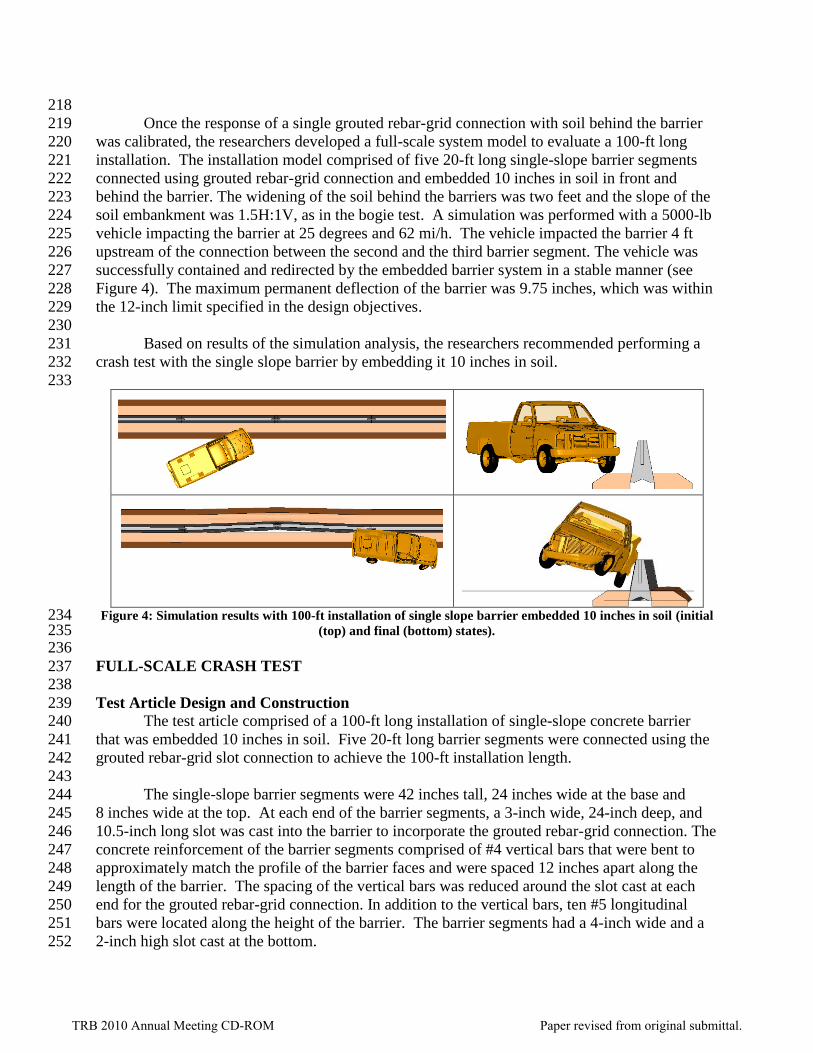
Once the response of a single grouted rebar-grid connection with soil behind the barrier 219
was calibrated, the researchers developed a full-scale system model to evaluate a 100-ft long 220
installation. The installation model comprised of five 20-ft long single-slope barrier segments 221
connected using grouted rebar-grid connection and embedded 10 inches in soil in front and 222
behind the barrier. The widening of the soil behind the barriers was two feet and the slope of the 223
soil embankment was 1.5H:1V, as in the bogie test. A simulation was performed with a 5000-lb 224
vehicle impacting the barrier at 25 degrees and 62 mi/h. The vehicle impacted the barrier 4 ft 225
upstream of the connection between the second and the third barrier segment. The vehicle was 226
successfully contained and redirected by the embedded barrier system in a stable manner (see 227
Figure 4). The maximum permanent deflection of the barrier was 9.75 inches, which was within 228
the 12-inch limit specified in the design objectives. 229
230
Based on results of the simulation analysis, the researchers recommended performing a 231
crash test with the single slope barrier by embedding it 10 inches in soil. 232
233
Figure 4: Simulation results with 100-ft installation of single slope barrier embedded 10 inches in soil (initial 234
(top) and final (bottom) states). 235 236
FULL-SCALE CRASH TEST 237 238
Test Article Design and Construction 239 The test article comprised of a 100-ft long installation of single-slope concrete barrier 240
that was embedded 10 inches in soil. Five 20-ft long barrier segments were connected using the 241
grouted rebar-grid slot connection to achieve the 100-ft installation length. 242
243
The single-slope barrier segments were 42 inches tall, 24 inches wide at the base and 244
8 inches wide at the top. At each end of the barrier segments, a 3-inch wide, 24-inch deep, and 245
10.5-inch long slot was cast into the barrier to incorporate the grouted rebar-grid connection. The 246
concrete reinforcement of the barrier segments comprised of #4 vertical bars that were bent to 247
approximately match the profile of the barrier faces and were spaced 12 inches apart along the 248
length of the barrier. The spacing of the vertical bars was reduced around the slot cast at each 249
end for the grouted rebar-grid connection. In addition to the vertical bars, ten #5 longitudinal 250
bars were located along the height of the barrier. The barrier segments had a 4-inch wide and a 251
2-inch high slot cast at the bottom. 252
TRB 2010 Annual Meeting CD-ROM Paper revised from original submittal.

253
The barrier was embedded in crushed limestone road base material that conformed to 254
MASH standard soil. To embed the barrier a 2-ft depth of the native soil adjacent to the testing 255
facility’s concrete pavement was excavated. The excavated area was then backfilled with 256
standard MASH soil and compacted in approximately 6-inch lifts. Once the backfill soil reached 257
a level of 10 inches below the concrete pavement surface, the barrier was set in place and further 258
soil was added and compacted in front and back of the barrier. The barrier was placed adjacent to 259
the concrete pavement at a 1-ft lateral offset. The soil widening behind the barrier was 2 ft. As 260
the soil was backfilled, a 1.5H:1V slope was built into the embankment. 261
262
A rebar-grid was then dropped into the slot at each barrier connection location. It 263
comprised of two vertical #6 bars that were spaced 10 inches apart, and three longitudinal #8 264
bars that were spaced eight inches apart. With the rebar-grid in place, the connection was grouted 265
using a non-shrink grout. Details of the test article and its installation are shown in Figure 5. 266
267
The concrete of the barrier was specified to have a minimum compressive strength of 268
4000 psi. The reinforcing steel was specified to be grade 60 steel. The steel material used for 269
manufacturing the rebar-grid was also specified to be grade 60. The grout used for making the 270
connection was a non-shrink grout with a minimum strength of 4000 psi. The soil used for 271
embedding the barriers was crushed limestone road base material that conforms to standard 272
MASH soil. The moisture content of the soil on the day of the test was 8.5%. 273
274
The process of embedding the barrier in the field may be different from the test. The 275
barrier can be installed by first compacting the soil to roadway surface and then excavating a 2-ft 276
wide area for embedding the barrier. Once the barrier has been placed, some level of compaction 277
may be needed depending on site conditions. If compaction is needed behind the barrier, a 278
compactor placed on a swing arm can be used. 279
280
281
TRB 2010 Annual Meeting CD-ROM Paper revised from original submittal.

Figure 5: Test article details and barrier installation. 282
283
Testing Requirements 284 According to MASH, two tests are recommended to evaluate longitudinal barriers for test 285
level three (TL-3) as described below. 286
TRB 2010 Annual Meeting CD-ROM Paper revised from original submittal.
287
1. MASH Test Designation 3-10: 2425 lb vehicle impacting the critical impact point (CIP) 288
of the length of need section at a speed of 62 mi/h and an angle of 25 degrees. 289
2. MASH Test Designation 3-11: 5000 lb pickup truck impacting the CIP of the length of 290
need section at a speed of 62 mi/h and an angle of 25 degrees. 291
292
The researchers performed test 3-11 of MASH (i.e. 5000 lb vehicle, 62 mi/h, 25 degrees) 293
on the design finalized from the simulation effort to verify simulation results. It was argued that 294
this is the critical test for the design and the test with smaller 2425 lb vehicle is not needed. Due 295
to higher impact energy, the test with the 5000 lb pickup truck will result in greater lateral 296
deflection and help evaluate connection strength and the tendency of the barriers to rotate. An 297
impact resulting from the lighter 2425 lb passenger car under same impact speed and angle will 298
not result in any increase in lateral deflection of the barrier nor will it impart a higher force on 299
the barrier to evaluate connection strength and barrier rotation. Furthermore, due to the small 300
deflection expected in the test, the small car impact with the embedded single-slope barrier will 301
be no different than the rigid single-slope barrier. Thus, the test was conducted with the 5000 lb 302
pickup only. 303
304
Test Description 305 MASH test 3-11 involves a 2270P vehicle weighing 5000 lb ±100 lb and impacting the 306
barrier at an impact speed of 62.2 mi/h ±2.5 mi/h and an angle of 25 degrees ±1.5 degrees. A 307
2002 Dodge pickup truck was used in the test, which weighed 4953 lb. The vehicle impacted the 308
barrier with a speed and angle of 63.1 mi/h and 24.2 degrees, respectively. The test impact point 309
was 62.0 inches upstream of the joint between segments 2 and 3. At approximately 0.042 s, the 310
left front tire began to climb the face of the barrier and the vehicle began to redirect. At 0.169 s, 311
the vehicle began to travel parallel to the barrier while traveling at a speed of 58.7 mi/h. At 312
0.173 s, the right rear of the vehicle contacted the barrier, and at 0.176 s, the vehicle began to roll 313
clockwise. The right rear corner of the bed of the vehicle contacted the top of the barrier at 314
0.616 s, and after that, dust obscured the view in all camera views. Brakes on the vehicle were 315
applied at 1.5 s after impact, and the vehicle came to rest 247 ft downstream of impact and 10 ft 316
toward traffic lanes. 317
318
Damage to Test Installation 319 Damage to the impacted barrier segments was minimal as shown in Figure 6-a. Tire 320
marks were on the traffic face of the barrier and there was no evidence of cracking in the barrier. 321
Length of contact of the vehicle with the barrier was 14.0 ft. Maximum permanent deflection of 322
the barrier was 5.5 inches. The working width was 19.6 inches. Maximum dynamic deflection 323
during the test was 5.6 inches. 324
325
Vehicle Damage 326 The 2270P vehicle sustained damage to the right front corner and along the right side, as 327
shown in Figure 6-b. The right upper A-arm, right tie rod end, and sway bar were deformed. 328
Also damaged were the front bumper, grill, right front fender, right front and rear doors, right 329
exterior side of bed, rear bumper, and tailgate. The right front and rear wheel rims were 330
deformed and the right front tire was deflated. Maximum exterior crush to the vehicle was 14.0 331
TRB 2010 Annual Meeting CD-ROM Paper revised from original submittal.

inches in the side plane at the right front corner at bumper height. Maximum occupant 332
compartment deformation was 0.5 inches in the right front door at hip height. 333
334
Occupant Risk Factors 335 Data from the accelerometer, located at the vehicle’s center of gravity, were digitized for 336
evaluation of occupant risk and were computed as follows. In the longitudinal direction, the 337
occupant impact velocity was 12.1 ft/s (3.7 m/s) at 0.090 s, the highest 0.010-s occupant 338
ridedown acceleration was -2.4 Gs from 0.173 to 0.183 s, and the maximum 0.050-s average 339
acceleration was -6.5 Gs between 0.009 and 0.059 s. In the lateral direction, the occupant impact 340
velocity was 24.6 ft/s (7.5 m/s) at 0.090 s, the highest 0.010-s occupant ridedown acceleration 341
was -11.3 Gs from 0.187 to 0.197 s, and the maximum 0.050-s average was -13.0 Gs between 342
0.026 and 0.076 s. These data and other pertinent information from the test are summarized in 343
Figure 7. 344
345
Assessment of Test Results 346 An assessment of the crash test based on the applicable MASH08 safety evaluation criteria is 347
presented in Table 1. As shown, the embedded single slope barrier with grouted rebar grid 348
connection was judged to meet all the required impact performance criteria for a TL-3 impact. 349
TRB 2010 Annual Meeting CD-ROM Paper revised from original submittal.

350
(a) Test article damage
(b) Vehicle damage
Figure 6: Test article and vehicle damage. 351
TRB 2010 Annual Meeting CD-ROM Paper revised from original submittal.

Sheikh, Bligh, Albin, and Olson 14
0.000 s
0.098 s
0.296 s
0.393 s
352 General Information Test Agency .............................. Test No. ................................... Date .......................................... Test Article Type .......................................... Name ........................................ Installation Length ..................... Material or Key Elements .......... Soil Type and Condition ............. Test Vehicle Type/Designation ...................... Make and Model ........................
Curb .......................................... Test Inertial ............................... Dummy...................................... Gross Static...............................
Texas Transportation Institute 40516-13-1 April 16, 2009 Concrete Barrier Single-Slope Barrier on 1.5H:1V Slope 100 ft 42-inch tall x 20 ft long single-slope concrete barrier embedded 10 inches in soil in front of 1.5H:1V slope Standard Soil, Dry 2270P 2002 Dodge Ram 1500 Pickup 4630 lb 4953 lb No Dummy 4953 lb
Impact Conditions Speed ........................................ Angle ......................................... Location/Orientation .................. Exit Conditions Speed ........................................ Angle ......................................... Occupant Risk Values Impact Velocity Longitudinal ............................ Lateral ....................................
Ridedown Accelerations Longitudinal ............................ Lateral .................................... THIV .......................................... PHD .......................................... Max. 0.050-s Average Longitudinal ............................ Lateral .................................... Vertical ...................................
63.1 mi/h 24.2 degrees 62 inch upstrm Joint 2-3 Out of view Out of view 12.1 ft/s 24.6 ft/s -2.4 G -11.3 G 29.6 km/h 11.3 G -6.5 G -13.0 G -4.2 G
Post-Impact Trajectory Stopping Distance ........................... Vehicle Stability
Maximum Yaw Angle ....................... Maximum Pitch Angle ...................... Maximum Roll Angle ........................ Vehicle Snagging............................. Vehicle Pocketing ............................ Test Article Deflections Dynamic .......................................... Permanent ....................................... Working Width ................................. Vehicle Damage VDS ................................................. CDC ................................................ Max. Exterior Deformation ............... OCDI Max. Occupant Compartment Deformation ...............................
247 ft dwnstrm 10 ft fwd -42 degrees -11 degrees 44 degrees No No 5.6 inches 5.5 inches 19.6 inches 01RFQ5 01RFEW4 14.0 inches 0.56 inch
Figure 7: Summary of results for MASH08 test 3-11 on the single-slope barrier on 1.5H:1V slope.353
TRB 2010 Annual Meeting CD-ROM Paper revised from original submittal.

Sheikh, Bligh, Albin, and Olson 15
Table 1 Performance evaluation summary for MASH08 test 3-11 on the single-slope barrier on slope. 354 Test Agency: Texas Transportation Institute Test No.: 405160-13-1 Test Date: 2009-04-16
MASH08 Evaluation Criteria Test Results Assessment
Structural Adequacy
A. Test article should contain and redirect the vehicle or bring
the vehicle to a controlled stop; the vehicle should not
penetrate, underride, or override the installation although
controlled lateral deflection of the test article is acceptable
The single-slope barrier in front of 1.5H:1V slope
contained and redirected the 2270P vehicle. The
vehicle did not penetrate, underride, or override the
installation. Maximum dynamic deflection during the
test was 5.6 inches.
Pass
Occupant Risk
D. Detached elements, fragments, or other debris from the test
article should not penetrate or show potential for
penetrating the occupant compartment, or present an undue
hazard to other traffic, pedestrians, or personnel in a work
zone.
No detached elements, fragments, or other debris
were present to penetrate or show potential to
penetrate the occupant compartment, or to present
undue hazard to others in the area.
Pass
Deformations of, or intrusions into, the occupant
compartment should not exceed limits set forth in Section
5.3 and Appendix E of MASH08.
Maximum occupant compartment deformation was
5.5 inches. Pass
F. The vehicle should remain upright during and after
collision. The maximum roll and pitch angles are not to
exceed 75 degrees.
The 2270P vehicle remained upright during and after
the collision event. Maximum roll was 44 degrees. Pass
H. Longitudinal and lateral occupant impact velocities should
fall below the preferred value of 9.1 m/s (30 ft/s), or at least
below the maximum allowable value of 12.2 m/s (40 ft/s).
Longitudinal occupant impact velocity was 12.1 ft/s,
and lateral occupant impact velocity was 24.6 ft/s. Pass
I. Longitudinal and lateral occupant ridedown accelerations
should fall below the preferred value of 15.0 Gs, or at least
below the maximum allowable value of 20.49 Gs.
Longitudinal ridedown acceleration was -2.4 G, and
lateral ridedown acceleration was -11.3 G. Pass
Vehicle Trajectory
For redirective devices, the vehicle shall exit the barrier
within the exit box.
The vehicle remained within the exit box. Pass
355
TRB 2010 Annual Meeting CD-ROM Paper revised from original submittal.

Sheikh, Bligh, Albin, and Oslon 16
SUMMARY AND CONCLUSIONS 356 The objective of the this research to develop a precast concrete barrier that can be placed 357
adjacent to steep slopes such as 1.5H:1V, without using a concrete moment slab. 358
359
The final design was incorporated 20-ft long precast single slope barrier segments with 360
grouted rebar grid connection. The 42-inch tall single slope barrier was preferred over other 361
concrete barrier types due to the ease of embedment without requiring changes in the barrier’s 362
profile. Since the performance of the grouted rebar-grid connection in a free-standing single 363
slope barrier was not known under MASH evaluation criteria, the researchers evaluated its 364
performance using a smaller scale bogie impact test and simulation analysis. It was determined 365
that the grouted rebar grid connection did not provide enough strength to restrict lateral 366
deflections. Results of the simulation analysis showed that large lateral deflection was expected 367
with the grouted rebar-grid connection when used with the single slope barrier in a free-standing 368
mode. 369
370
The researchers then evaluated restricting the deflection of the barrier by embedding it 10 371
inches in soil. The barrier was placed in front of a 1.5H:1V slope. The offset of the barrier from 372
the slope break point of the soil embankment was restricted to two feet. Another phase of bogie 373
testing and simulation analysis was performed to evaluate the performance of the grouted rebar 374
grid connection in the embedded barrier configuration. Results of the simulation analysis 375
showed that the embedded barrier system will result in acceptably reduced lateral deflections. 376
377
A full-scale crash test was subsequently performed to validate the design. The embedded 378
single-slope barrier in front of 1.5H:1V slope performed acceptably according to the 379
requirements of MASH. The permanent lateral deflection of the barrier was 5.5 inches. 380
381
The embedded single slope barrier application developed in this research is expected to 382
result in significant cost savings for the user transportation agencies. The benefit of this 383
application comes from the elimination of the use of a moment slab to restrict lateral barrier 384
deflection. The cost of constructing and installing the single slope barrier with a moment slab is 385
typically $375 per linear foot (based on recent bids received by Washington State Department of 386
Transportation). The cost of constructing and installing the embedded single slope barrier on the 387
other hand is approximately $75 per linear foot (based on test article construction in this 388
research). This implies a cost saving of nearly 80%. In addition, the use of a precast barrier 389
minimizes the amount of time to construct in traffic, which reduces traffic disruptions and 390
worker exposure. Eliminating the moment slab further reduces time by eliminating a 391
construction phase. 392
393
In comparison to some of the metal guardrail systems developed for use on slopes, the 394
initial cost of installing the embedded single slope barrier will be higher. However, due to its 395
small permanent deflection, the embedded barrier design is expected to require little or no 396
maintenance under most vehicle impacts. Since metal guardrail systems require significant 397
repair time and cost, the embedded barrier design developed in this research is expected to result 398
in significant lifecycle cost savings in areas where frequent vehicle hits are encountered. 399
400
401
TRB 2010 Annual Meeting CD-ROM Paper revised from original submittal.

Sheikh, Bligh, Albin, and Oslon 17
ACKNOWLEDGMENTS 402 This research was performed under a pooled fund program between the State of Alaska 403
Department of Transportation and Public Facilities, California Department of Transportation 404
(Caltrans), Louisiana Department of Transportation and Development, Minnesota Department of 405
Transportation, Tennessee Department of Transportation, Texas Department of Transportation 406
and Washington State Department of Transportation, and the Federal Highway Administration 407
(study number TPF-5(114)). The authors acknowledge and appreciate their guidance and 408
assistance. 409
410
TRB 2010 Annual Meeting CD-ROM Paper revised from original submittal.

Sheikh, Bligh, Albin, and Oslon 18
REFERENCES 411 412
1. K.A. Polivka, D.L. Sicking, R.K. Faller, and J.R. Rohde, "A W-Beam Guardrail Adjacent 413
to a Slope." Transportation Research Record 1743 (2001) 80-87. 414
415
2. American Association of State Highway and Transportation Officials. Manual for 416
Assessing Safety Hardware. Ballot Draft, February 2008. 417
418
3. W.L. Beason, H.E. Ross, Jr., H.S. Perera, W.L. Campise, and D.L. Bullard, Jr. 419
“Development of a Single-slope Concrete Median Barrier.” Texas Transportation 420
Institute, Texas, 1989. 421
422
4. N.M. Sheikh, R.P. Bligh, and W.L. Menges, “Development and Testing Of a Concrete 423
Barrier Design for Use In Front of Slope or on MSE Wall.” Report 405160-13-1, Texas 424
Transportation Institute, Texas, 2009. 425
426
5. Ross, Jr., H.E., Sicking, D.L., Zimmer, R.A. and Michie, J.D., “Recommended 427
Procedures for the Safety Performance Evaluation of Highway Features,” National 428
Cooperative Highway Research Program Report 350, Transportation Research Board, 429
National Research Council, Washington, D.C., 1993. 430
431
TRB 2010 Annual Meeting CD-ROM Paper revised from original submittal.