Embed Size (px)
Citation preview
Application of digital 3D models on urbanplanning and highway design.L.A. Hernández & S. HernándezETS de Ingenieros de Caminos, Canales y Puertos, Universidad deLa Coruña, Campus de Elviña, 15071 La Coruña, SpainEmail: [email protected]
Abstract
Several advantages of producing 3D digital models of civil engineering designs and the waythis advanced tool overcomes drawbacks inherent to the conventional design process isexplained in this paper. Three cases, namely, a two level road junction, a new highway and anew university campus are included to emphasise the feasibility of 3D digital models in reallife projects. Several advanced visualization techniques have been used in the examplespresented, which correspond to real practical problems
1 Digital 3D models and civil engineering design
During the last decade, CAD techniques have been progressively implementedin areas of urban design. Urban planning, construction, facilities layout,transport and traffic management are actually fields in which projects are madeover a computer techniques basement. Along those years, processes andalgorithms for 3D representation of digital models arose and consolidated,although the degree of implementation on each field of sciences and techniquesvaries.
In this sense, the presence of methods for tridimensional representationin the topics of roads and transport systems has been mainly sparse.Nevertheless, they appear to be a very powerful tool to be applied in everystage of the project-construction-finished work process. The followingparagraphs will be devoted to ilustrate this idea when applied to real designproblems.
Digital 3D models feed the project with an extra amount of informationthat is not available in traditional computer tools (2D-CAD, GIS). Thisadvantage produces some new benefits that could be related to two maincategories connected to the visual features of the finished work and the virtualconstruction of the project.
1.1 Visual features of the finished work
1.1.1 AppearanceMost of the objects involved in urban design are made not only to be used butalso to be seen. Their appearance is difficult to describe solely by usingtechnical drawings, and many visual features such as material types,lightning, or even meteorological effects are easy to implement on a 3Dvisualization of the object.
1.1.2 Visual impactMany times, the environment where the object is to be built becomes asimportant as the new construction. Studies dealing with environmental impactcan turn a big profit from the simulation of the future of the areas affected bynew projects.
1.1.3 Visibility checking.This feature is specially important in projects related to road and rail networksto assure a correct visibility in crossings, junctions, slope changes and signs toprevent risk of accidents and black points.
To simulate such perception by the use of 2D drawings is a difficulttask, considering that tridimensional vision along with perspective effects areinvolved.
1.1.4 SimulationRecreation of future trajectories gives a worthy amount of information forurban transport projects. Inclusion of a virtual camera moving along futurepaths following the expected velocity curves, makes possible to evaluate manyimportant features of the design .
1.2 Virtual construction of the project.
1.2.1 Geometrical coherenceExperience in 3D modelling of projects gives the evidence of the difficulty toreach a geometrically correct complex design when represented only by using2D drawings. Plans, elevations and cross sections make a limited set ofrepresentative projections of the future design and do not contain the fullgeometrical data of the object itself. Thus, it is easy to find areas not defined,ambiguities and even mistakes caused by the lack of a system capable to verifythe tridimensional coherence of the design by putting together and comparingall the data contained in the drawings.
On the other hand, a 3D model is a geometrical clone of the objectitself, fully defined in its three dimensions inside the computer. From thismodel plans and views can be obtained in the same way the designer drafts theplans from the object in his mind. The difference resides in the fact that the
model compared with the imagined object is geometrically complete, withoutundefined parts or ambiguities.
1.2.2 Hidden mistakes and error detectionFrom the above mentioned , It could be inferred that traditional projectscontains a grater number of mistakes as their geometrical complexity increases.Projects related to communication facilities and road networks fall in suchcategory for they involve sets of shapes with very different properties that areto be assembled together (roads, terrain, pipelines, buildings, structures,underground tunnels, mechanical objects, vegetation, etc.)
The generation of a 3D model is by itself a good system of errorchecking for it represents a virtual construction of the design using thedrawings as an initial source of data. The budget devoted to correct suchmistakes by making a 3D digital model is several orders of magnitude lowerthan if detected during the construction works.
1.2.3 Volume analysis3D models are very suitable for mathematical analysis. That feature makeseasy to obtain volumetric data to be processed as needed. Volume ofexcavations, inercy and other mechanical parameters, interference andcollision detection and any result concerning with volumes can be easilyachieved.
1.2.4 BroadcastingThe fact of having a built version of the project, even a virtual one capable tobe assigned with realistic attributes allows the designer to produce pictures andanimations of the future works. Such media can be used to advertise the projecton TV, press and exhibitions, giving an undoubtedly added value to the 3Dmodel.
2.- Accuracy and digital models
It is necessary to clarify the concept of precise digital models. 3D computergraphics are now part of almost any production on the film, video andmultimedia industry. Many times any model with realistic appearance isconsidered a valid one . This assertion could be true is such above mentionedindustries where visual appearance is all, but for a model to be suitable to beused in technical tasks the level of accuracy has the same or greater importancethat realism.
It is possible to generate a 3D model to produce realistic pictures of adesign by substituting geometrical elements with other visual effects of similarappearance (one of such techniques consist on the application of photographsover a very simple geometry to avoid modelling the details in the form oftexture mapping). That approximation must be used with ultimate care, for itavoids to appreciate the real shape of the objects in a close analysis. A digital
model to be used for design requires an accurate and full description of everyobject, otherwise, the results can be realistic but deceitful.
It is obvious that the level of accuracy will be according with the size ofthe model and the relative importance of its parts. As an example, the computervisualisation of a highway can have a precision of a centimetre in the roadand several meters in the simulation of the satellite view of the geographic areawhere it is located. This can be achieved in a unique model to be used for bothpurposes.
3.- Examples of application
3.1 Urban road networks. Application to a two level junction project.
This example will show the application of a digital 3D model in the designphase of a future road intersection in a highly consolidated urban area.
3.1.1 Social considerationsUrban roadworks usually generate social debate, making that kind of projectsto be evaluated by the citizens with very faultfinding spirit. The political costcan raise to be specially important because, although they are promoted toimprove the conditions of the area or the city as a whole, they also carryinconveniences that affect exclusively the zone in which the works are going totake place in the form of radical changes in the aspect of the area, sometimeswith demolition of houses and dislodgement.
The digital 3D model may serve to take decisions related to this items,since it will help a lot to appreciate the real visual impact, and to verify the realneed to demolish buildings. Representing the area using computer modelsallows to incorporate the future project in the actual area. Thus, computerimages can be made from any target viewpoint and then compared with actualviews. Morphing techniques can be applied to accentuate the magnitude ofvisual changes and their effect over the urban environment.
These techniques provides easy and comprehensible documents that canbe displayed to the affected citizens, and can be also used as a reference forcomplains that have to be presented in front of this computer generated viewsof the area, avoiding disagreement often based upon suppositions mostlyproduced from a bad understanding of technical drawings that only inspire tothe inhabitants an uncertain future for the zone.
3.1.2 Description of the modelThe works related in the study are located in an urban area inside the city of LaCoruña, in the Northwest of Spain. The zone was to be redesigned due to theheavy amount of traffic. Therefore, an existing avenue was to be converted intoa two levels junction. For obtaining that, some existing buildings should bedemolished allowing room for widening the avenues, to build a roundabout inthe lower level and a bridge for the upper one.
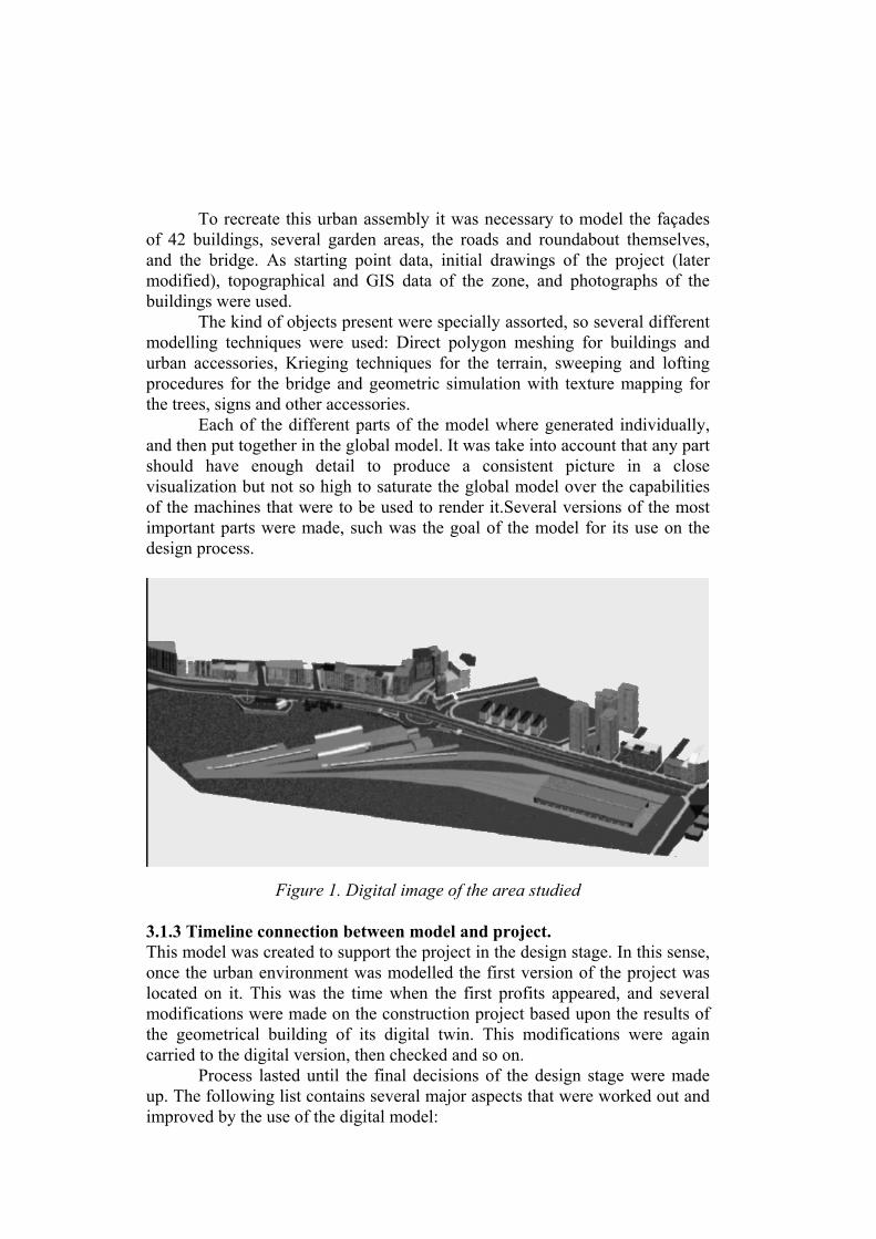
To recreate this urban assembly it was necessary to model the façadesof 42 buildings, several garden areas, the roads and roundabout themselves,and the bridge. As starting point data, initial drawings of the project (latermodified), topographical and GIS data of the zone, and photographs of thebuildings were used.
The kind of objects present were specially assorted, so several differentmodelling techniques were used: Direct polygon meshing for buildings andurban accessories, Krieging techniques for the terrain, sweeping and loftingprocedures for the bridge and geometric simulation with texture mapping forthe trees, signs and other accessories.
Each of the different parts of the model where generated individually,and then put together in the global model. It was take into account that any partshould have enough detail to produce a consistent picture in a closevisualization but not so high to saturate the global model over the capabilitiesof the machines that were to be used to render it.Several versions of the mostimportant parts were made, such was the goal of the model for its use on thedesign process.
Figure 1. Digital image of the area studied
3.1.3 Timeline connection between model and project.This model was created to support the project in the design stage. In this sense,once the urban environment was modelled the first version of the project waslocated on it. This was the time when the first profits appeared, and severalmodifications were made on the construction project based upon the results ofthe geometrical building of its digital twin. This modifications were againcarried to the digital version, then checked and so on.
Process lasted until the final decisions of the design stage were madeup. The following list contains several major aspects that were worked out andimproved by the use of the digital model:
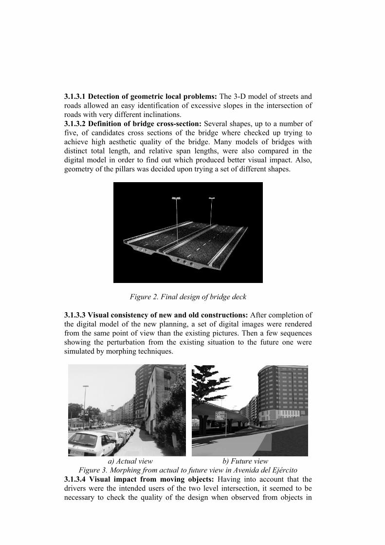
3.1.3.1 Detection of geometric local problems: The 3-D model of streets androads allowed an easy identification of excessive slopes in the intersection ofroads with very different inclinations.3.1.3.2 Definition of bridge cross-section: Several shapes, up to a number offive, of candidates cross sections of the bridge where checked up trying toachieve high aesthetic quality of the bridge. Many models of bridges withdistinct total length, and relative span lengths, were also compared in thedigital model in order to find out which produced better visual impact. Also,geometry of the pillars was decided upon trying a set of different shapes.
Figure 2. Final design of bridge deck
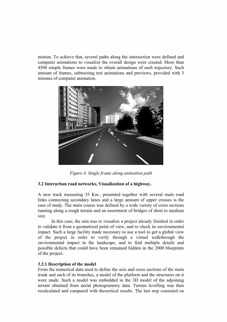
3.1.3.3 Visual consistency of new and old constructions: After completion ofthe digital model of the new planning, a set of digital images were renderedfrom the same point of view than the existing pictures. Then a few sequencesshowing the perturbation from the existing situation to the future one weresimulated by morphing techniques.
a) Actual view b) Future view
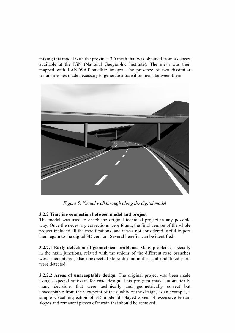
Figure 3. Morphing from actual to future view in Avenida del Ejército3.1.3.4 Visual impact from moving objects: Having into account that thedrivers were the intended users of the two level intersection, it seemed to benecessary to check the quality of the design when observed from objects in
motion. To achieve that, several paths along the intersection were defined andcomputer animations to visualize the overall design were created. More than4500 simple frames were made to obtain animations of each trajectory. Suchamount of frames, subtracting test animations and previews, provided with 3minutes of computer animation.
Figure 4. Single frame along animation path
3.2 Interurban road networks, Visualization of a highway.
A new track measuring 35 Km., presented together with several main roadlinks connecting secondary lanes and a large amount of upper crosses is thecase of study. The main course was defined by a wide variety of cross sectionsrunning along a rough terrain and an assortment of bridges of short to mediumsize.
In this case, the aim was to visualize a project already finished in orderto validate it from a geometrical point of view, and to check its environmentalimpact. Such a large facility made necessary to use a tool to get a global viewof the project in order to verify through a virtual walkthrough theenvironmental impact in the landscape, and to find multiple details andpossible defects that could have been remained hidden in the 2000 blueprintsof the project.
3.2.1 Description of the modelFrom the numerical data used to define the axis and cross sections of the maintrunk and each of its branches, a model of the platform and the structures on itwere made. Such a model was embedded in the 3D model of the adjoiningterrain obtained from aerial photogrametry data. Terrain levelling was thenrecalculated and compared with theoretical results. The last step consisted on
mixing this model with the province 3D mesh that was obtained from a datasetavailable at the IGN (National Geographic Institute). The mesh was thenmapped with LANDSAT satellite images. The presence of two dissimilarterrain meshes made necessary to generate a transition mesh between them.
Figure 5. Virtual walkthrough along the digital model
3.2.2 Timeline connection between model and projectThe model was used to check the original technical project in any possibleway. Once the necessary corrections were found, the final version of the wholeproject included all the modifications, and it was not considered useful to portthem again to the digital 3D version. Several benefits can be identified:
3.2.2.1 Early detection of geometrical problems. Many problems, speciallyin the main junctions, related with the unions of the different road brancheswere encountered, also unexpected slope discontinuities and undefined partswere detected.
3.2.2.2 Areas of unacceptable design. The original project was been madeusing a special software for road design. This program made automaticallymany decisions that were technically and geometrically correct butunacceptable from the viewpoint of the quality of the design, as an example, asimple visual inspection of 3D model displayed zones of excessive terrainslopes and remanent pieces of terrain that should be removed.
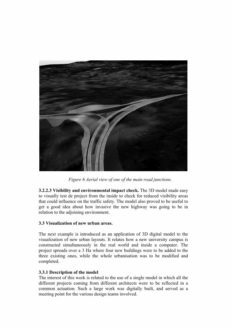
Figure 6 Aerial view of one of the main road junctions.
3.2.2.3 Visibility and environmental impact check. The 3D model made easyto visually test de project from the inside to check for reduced visibility areasthat could influence on the traffic safety. The model also proved to be useful toget a good idea about how invasive the new highway was going to be inrelation to the adjoining environment.
3.3 Visualization of new urban areas.
The next example is introduced as an application of 3D digital model to thevisualization of new urban layouts. It relates how a new university campus isconstructed simultaneously in the real world and inside a computer. Theproject spreads over a 3 Ha where four new buildings were to be added to thethree existing ones, while the whole urbanisation was to be modified andcompleted.
3.3.1 Description of the modelThe interest of this work is related to the use of a single model in which all thedifferent projects coming from different architects were to be reflected in acommon actuation. Such a large work was digitally built, and served as ameeting point for the various design teams involved.
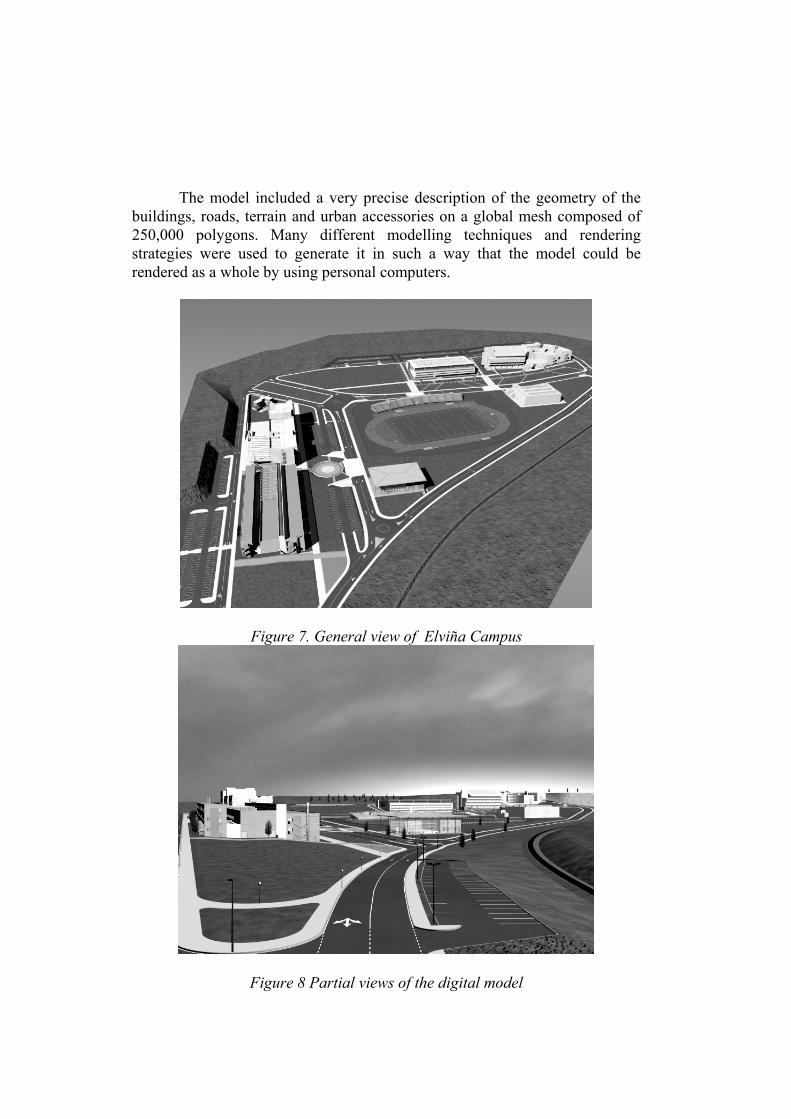
The model included a very precise description of the geometry of thebuildings, roads, terrain and urban accessories on a global mesh composed of250,000 polygons. Many different modelling techniques and renderingstrategies were used to generate it in such a way that the model could berendered as a whole by using personal computers.
Figure 7. General view of Elviña Campus
Figure 8 Partial views of the digital model
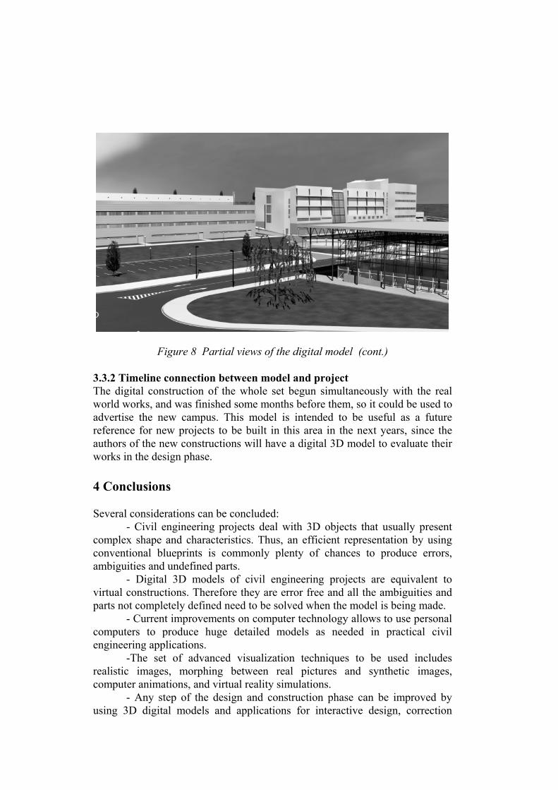
Figure 8 Partial views of the digital model (cont.)
3.3.2 Timeline connection between model and projectThe digital construction of the whole set begun simultaneously with the realworld works, and was finished some months before them, so it could be used toadvertise the new campus. This model is intended to be useful as a futurereference for new projects to be built in this area in the next years, since theauthors of the new constructions will have a digital 3D model to evaluate theirworks in the design phase.
4 Conclusions
Several considerations can be concluded:- Civil engineering projects deal with 3D objects that usually present
complex shape and characteristics. Thus, an efficient representation by usingconventional blueprints is commonly plenty of chances to produce errors,ambiguities and undefined parts.
- Digital 3D models of civil engineering projects are equivalent tovirtual constructions. Therefore they are error free and all the ambiguities andparts not completely defined need to be solved when the model is being made.
- Current improvements on computer technology allows to use personalcomputers to produce huge detailed models as needed in practical civilengineering applications.
-The set of advanced visualization techniques to be used includesrealistic images, morphing between real pictures and synthetic images,computer animations, and virtual reality simulations.
- Any step of the design and construction phase can be improved byusing 3D digital models and applications for interactive design, correction
checking phase and cumulative design have been presented in the adjoiningexamples.
References
1 Hernández, L.A, Hernández, S. Animation of a Two Level Road Intersectionin La Coruña. (de. S.Hernández, C.A. Brebbia) Proceedings of the 2nd Int.Conf. on Visualization and Intelligent Design In Engineering andArchitecture. La Coruña, Spain, 1995. Computational MechanicsPublications, Southampton 1995.
2 Hernández, S. Hernández, L.A. Visualización Avanzada en el Proyecto deCarreteras..(ed. Colegio de Ingenieros de Caminos, Canales y Puertos)Proceedings of 1st Galician Conference on Roads La Coruña, Spain 1995.
3 Hernández, S. Hernández, L.A. Advanced Visualization and ComputerAnimation in Engineering and Architectural Design. Proceedings ofICCE’96 International Conference on Civil Engineering. Bahrain, Abril1996.