Embed Size (px)
Citation preview
Application of DoDAF 2.0 for NOAA’s JPSS Ground System and Project
Robert Morgenstern Presenting Authors: Robert Morgenstern, 240-684-0648, [email protected] NASA Goddard Space Flight Center, Code 581/474 8800 Greenbelt Road Greenbelt, MD 20771 Jeff Hayden, 303-703-6911 / 240-684-0982, [email protected] Alan Jeffries, 703-582 0228/ 240 684 0982, [email protected] Laura Ellen Dafoe, (303) 721-6011, [email protected] Jeffries Technology Solutions, Herndon VA 20170
© 2013 by Na#onal Aeronau#cs and Space Administra#on. Published by The Aerospace Corpora:on with permission.
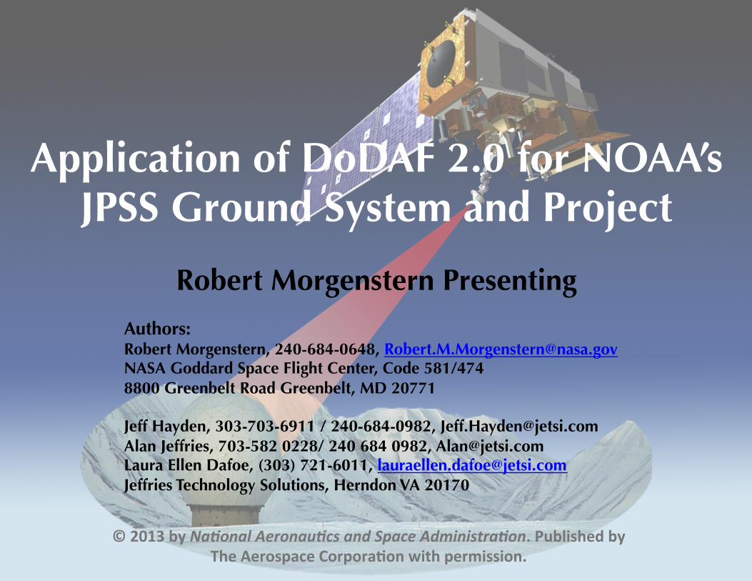
OV-1 JPSS Ground Systems ���High Level Operational Concept
JPSS-n
GCOM-n
TDRSS
Stored Mission Data
Telemetry Tracking & Control
Legend:Retain Intermediate product (RIP)
Data Quality Report
Mission Support Data
GCOM@ KSAT
GCOM SMDWSC
DR Terminals
Field Terminals
Jan 25, 2013
HRD LRD MSD
Operations Coordination
Launch Support, Commissioning & Contingency(Example of Use)
MSDFDF
Ancillary Data, ODAD, SDAD, CODAD
EUMETSATOps & DP
xDRs / Metadata
X-BandKa-Band
X-BandX-Band
X-BandS-Band
NWS TG (NOAA)
FNMOC
AFWA
EOS / NASA POP
Provides Enterprise Management & Ground Operations, Flight Operations, Data Acquisition, Data Routing, Data Product Generation, Data Product Cal/Val and Direct Readout Support services
Joint Polar Satellite System (JPSS) Ground System
GPS (&TTC?) Crypto Keys
GPS
Other LCFs (inc.
STAR)
Algorithm Updates
NASA/NSF @ McMurdo
LaunchSupport
NESDIS/ESPC
(NOAA)
NAVO-CEANO
X-Band
DMSP-FnMetop-n
S-‐NPP
X-Band
Coriolis / WindSat
DMSP Ops
(NOAA /6 SOPS)
WindSatDP
(FNMOC via DISA)
DMSP DP(AFWA)
CLASS(NOAA)
CoriolisOps
(NRL BP)
SDS
GCOM Ops
(JAXA)
WOTIS
CERES DP(LaRC)
S-NPP CERES
RDRs only
APs only
L/S-BandNSF @
CO
NSF internet services
EOS/NASA Missions
X-BandNASA
@ KSAT
AGS
SMD Backup
APs only
NSA
CARA
LASP for FF
FF-n
L-BandS-Band
USMCC
Argos CLSGCOM SDR
2

Introduction – Modeling the ���JPSS GS Architecture with DoDAF 2
• The JPSS Ground System (GS) is a complex, globally operated environmental satellite control, data retrieval, data processing, and environmental data product distribution system. Items of complexity include a large number of: – stakeholders, – project processes, – relationships with development contractors, and – architectural modernization.
• The JPSS Ground Project (GP) uses the Department of Defense Architecture Framework version 2.0 (DoDAF 2.0) to manage and coordinate the GS development by identifying: – JPSS GS organizational structure and performers; – actions performed by the organizational entities; – information that must flow among the entities; the systems, functions, and actions that
enable realization of the JPSS capabilities; and, – information and data exchanged among performers and systems.
• This presentation focuses on the processes for providing the Sensor Data Records (SDRs) and Environmental Data Records (EDRs) that are reduced from the satellite data and distributed to the program customers.
– A global view of the JPSS GS architecture is given in “Defining the Complex JPSS Ground System in Pieces Using DoDAF 2.0 as Implemented with UPDM”, a paper presented at the AIAA Space 2012 in Pasadena, CA.
3
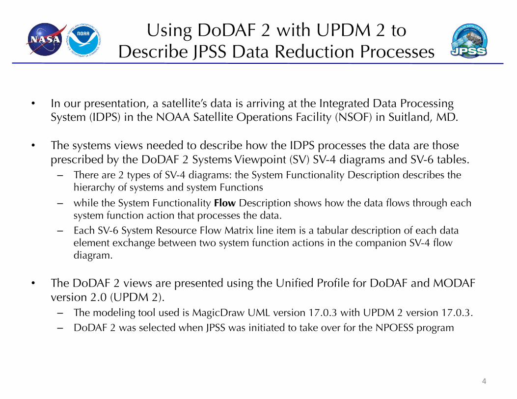
• In our presentation, a satellite’s data is arriving at the Integrated Data Processing System (IDPS) in the NOAA Satellite Operations Facility (NSOF) in Suitland, MD.
• The systems views needed to describe how the IDPS processes the data are those prescribed by the DoDAF 2 Systems Viewpoint (SV) SV-4 diagrams and SV-6 tables. – There are 2 types of SV-4 diagrams: the System Functionality Description describes the
hierarchy of systems and system Functions
– while the System Functionality Flow Description shows how the data flows through each system function action that processes the data.
– Each SV-6 System Resource Flow Matrix line item is a tabular description of each data element exchange between two system function actions in the companion SV-4 flow diagram.
• The DoDAF 2 views are presented using the Unified Profile for DoDAF and MODAF version 2.0 (UPDM 2). – The modeling tool used is MagicDraw UML version 17.0.3 with UPDM 2 version 17.0.3. – DoDAF 2 was selected when JPSS was initiated to take over for the NPOESS program
4
Using DoDAF 2 with UPDM 2 to Describe JPSS Data Reduction Processes
SV-4 System Functionality ���Description Diagrams
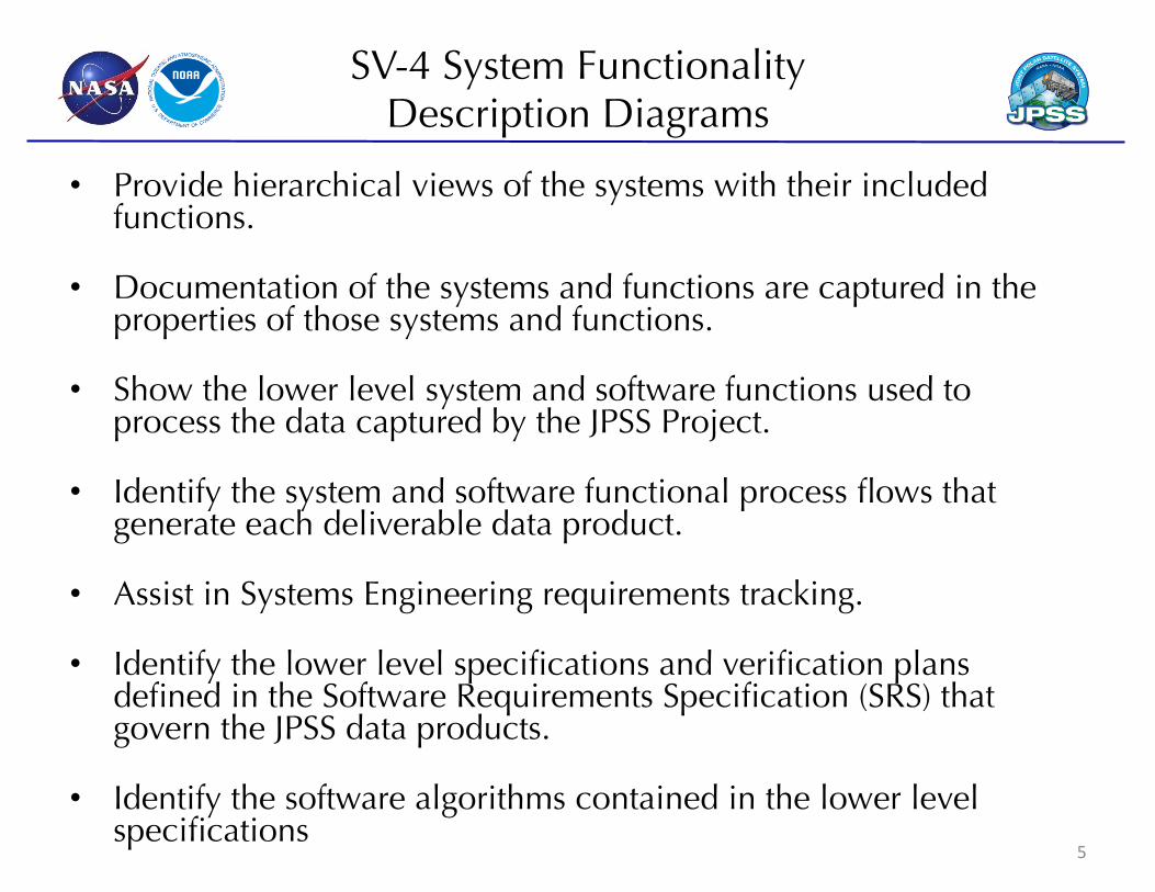
• Provide hierarchical views of the systems with their included functions.
• Documentation of the systems and functions are captured in the properties of those systems and functions.
• Show the lower level system and software functions used to process the data captured by the JPSS Project.
• Identify the system and software functional process flows that generate each deliverable data product.
• Assist in Systems Engineering requirements tracking.
• Identify the lower level specifications and verification plans defined in the Software Requirements Specification (SRS) that govern the JPSS data products.
• Identify the software algorithms contained in the lower level specifications
5
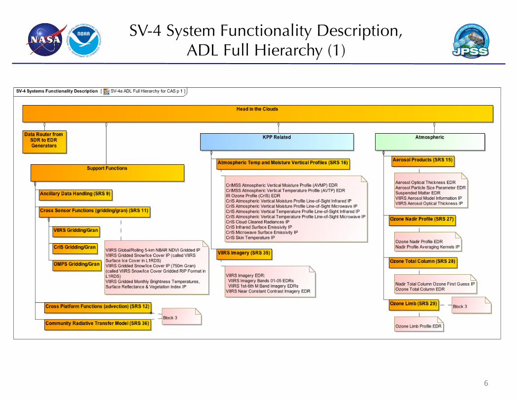
SV-4 System Functionality Description, ���ADL Full Hierarchy (1)
6
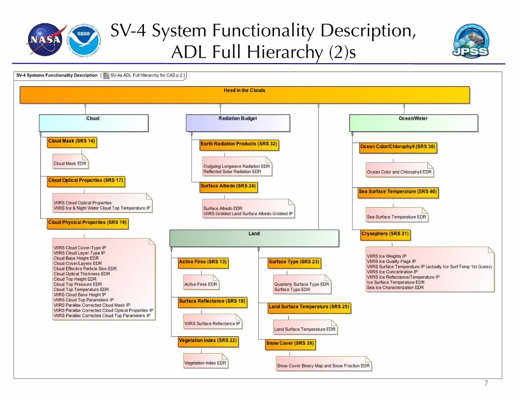
SV-4 System Functionality Description, ���ADL Full Hierarchy (2)s
7
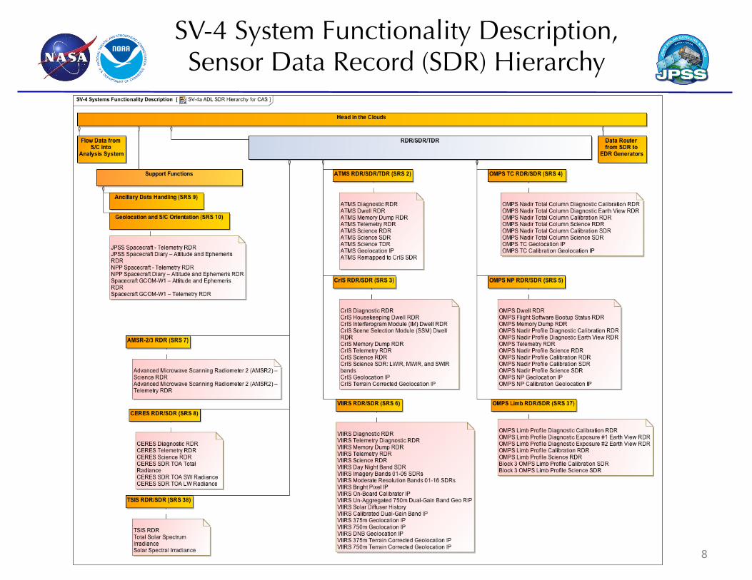
SV-4 System Functionality Description, ���Sensor Data Record (SDR) Hierarchy
8
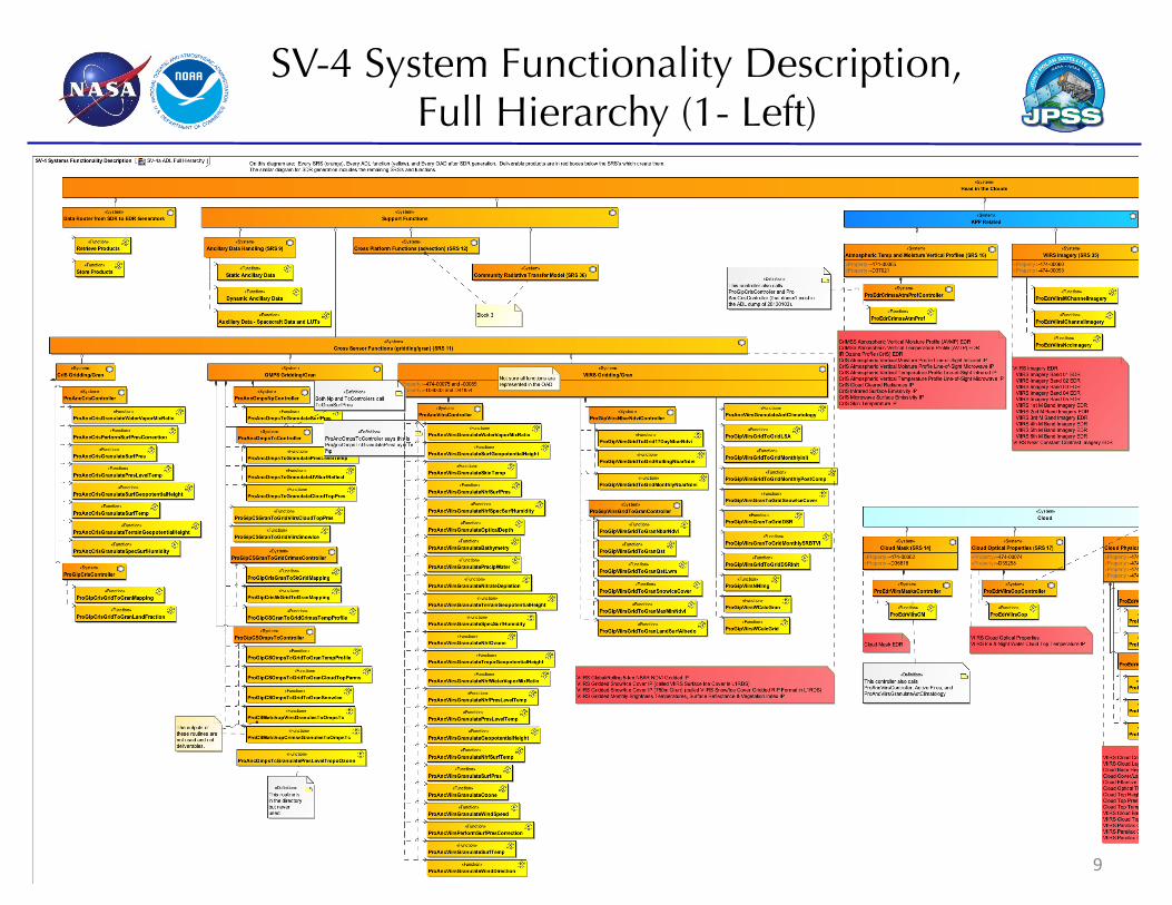
SV-4 System Functionality Description, ���Full Hierarchy (1- Left)
9
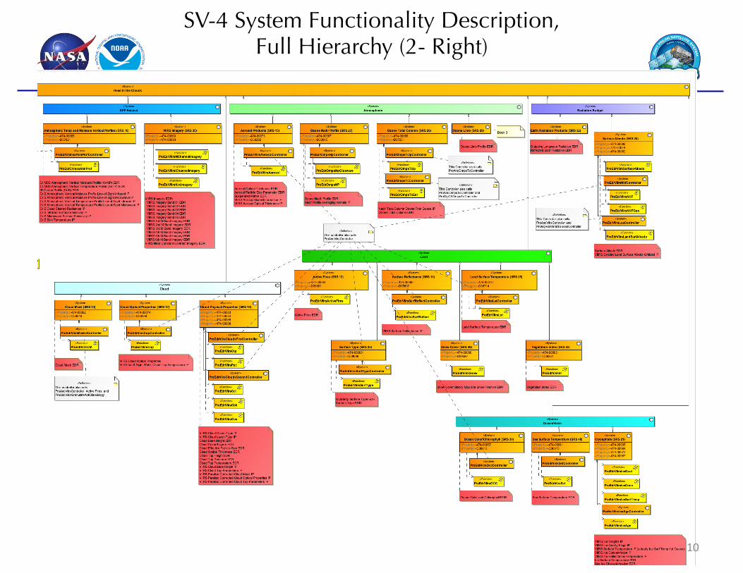
SV-4 System Functionality Description, ���Full Hierarchy (2- Right)
10
SV-4 System Functionality ���Flow Diagrams
• Used to describe system and software functional process flow to assist management and end user understanding of end product production.
• Inputs, outputs, and interdependencies are shown for each software process.
• Each horizontal swim lane is a system identified by the specification in the swim lane header – Input data flows from the top processes to each specification’s swim lane. – The data production process flows from FunctionAction (software object) to
FunctionAction to produce each swim lane’s data products – The deliverable products are at the far right of each swim lane.
• The SDR flow shows the analysis chain through SDRs, and the EDR flow shows the remainder of the chain through to the data products to be delivered to the Comprehensive Large Array-data Stewardship System, (CLASS). – Analysis of the interdependencies among the systems, software, and functional flows
help to identify downstream impacts when considering the scope of proposed changes or product degradation.
11
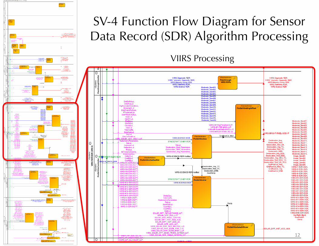
SV-4 Function Flow Diagram for Sensor Data Record (SDR) Algorithm Processing
VIIRS Processing
12
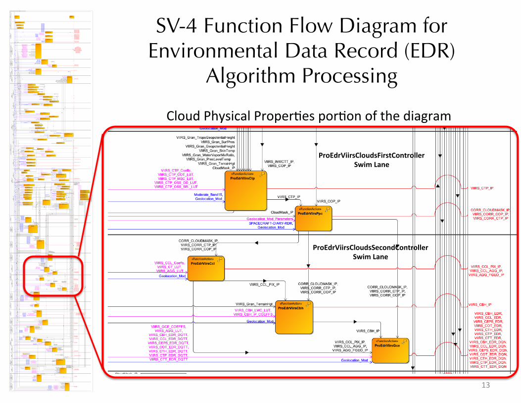
SV-4 Function Flow Diagram for Environmental Data Record (EDR)
Algorithm Processing
Cloud Physical Proper;es por;on of the diagram
ProEdrViirsCloudsSecondController Swim Lane
ProEdrViirsCloudsFirstController Swim Lane
13
SV-6 Systems Resource ���Flow Matrix
• Provides a tabular representation of the cross-swim lane resource traffic.
• Tracks resource flows from one swim lane’s FunctionAction to a FunctionAction in a different swim lane. – The flowing resources are identified – The resource producing and consuming swim lanes are identified as well
as the producing and consuming FunctionActions.
• The SV-6 provides a human-readable format of the input and output dependencies for each algorithm module.
14
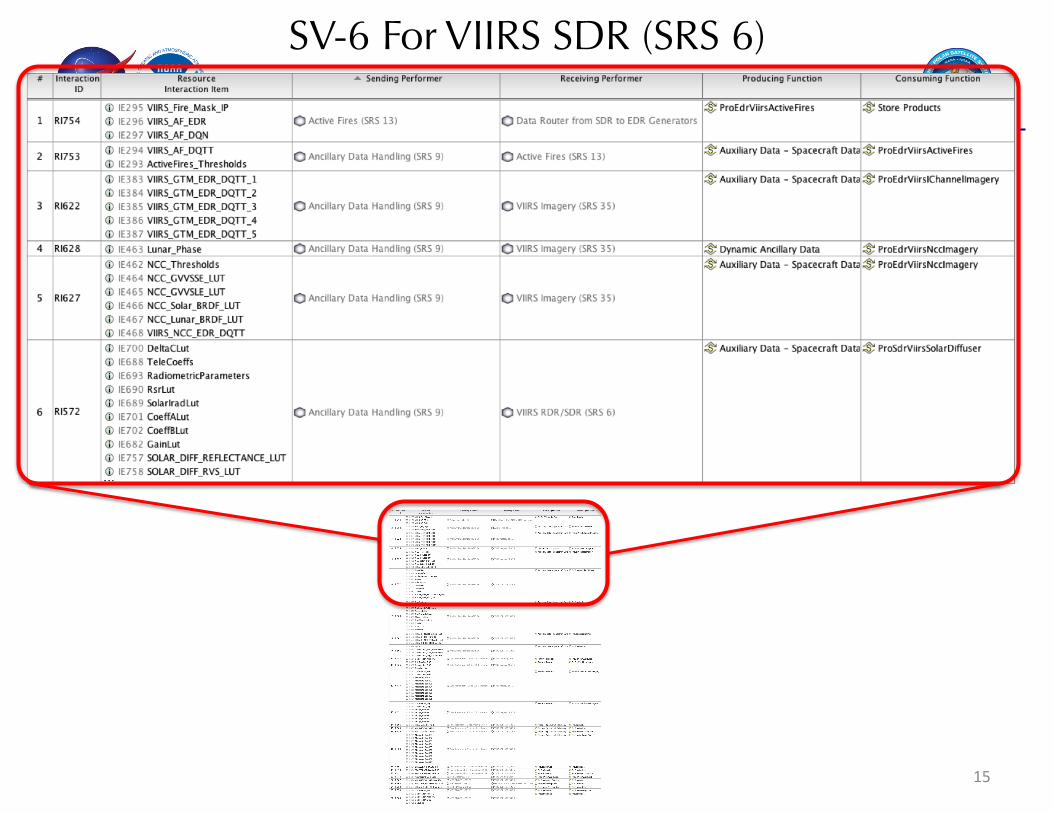
SV-6 For VIIRS SDR (SRS 6)
15
Summary
• The JPSS GS weather data processing architecture is very, very complex
• Identifying and managing all levels of product dependencies to ensure product performance has been a challenge – Previous attempts to capture have quickly fallen out of date as the massive data
flow and algorithm architecture evolved. – Flight system Cal/Val is scheduled to span months of data capture, reduction,
analysis and adjustment
• The application of DoDAF 2/UPDM 2 has provided a mechanism to capture and manage this complex data processing architecture. – Traces algorithm and data back to L1/L2 weather/climate performance metrics
• The tool automatically manages dependencies which used to be managed by engineering/scientific analysis.
• The application of DoDAF 2/UPDM 2 will lead to a more structured process at significantly reduced resource costs, enabling more efficient and faster evolution and progress.
16