Embed Size (px)
Citation preview
N. Limjeerajarus et al. / International Energy Journal 15 (2015) 43-56
www.rericjournal.ait.ac.th
43
Abstract – To fabricate a high performance polymer electrolyte fuel cell membrane electrode assembly (PEFC MEA), the hot press method is commonly used. For conducting the hot press method, the hot press machine which has very smooth contact surfaces of pressing blocks, accurate temperature and force loading control systems is required. Generally, a commercial hot press machine uses a hydraulic transmission system for load generation. However, it is considered to be relatively costly for such a small load of a small-scale PEFC application. In this study, to reduce the cost, a small-scale hot press machine has been designed and developed using a jackscrew instead of a hydraulic cylinder as the load transmitter. An investigation of stress, thermal stress, and deformation distributions of the hot press machine was carried out prior to actual manufacturing using finite element analysis. Finally, the developed small-scale hot press machine was experimentally checked so as to ensure that it can accurately be operated at the desired conditions, i.e., 130°C, 6 MPa with the smooth contact surfaces of its pressing blocks. Keywords – Finite element analysis, hot press machine, membrane electrode assembly, PEFC, structural analysis. 1. INTRODUCTION
Due to the increase in carbon dioxide level in the earth’s atmosphere, fuel cells become one of the most interesting energy converters for future power generation since they directly convert the chemical energy into electrical energy, resulting in very high energy conversion efficiency. Among various kinds of fuel cells, polymer electrolyte fuel cell (PEFC) is one of the strongest candidates for both automotive and stationary applications because of its simplicity in energy conversion with zero greenhouse gas emission, low temperature operation, low noise and vibration. The heart of a PEFC where electrochemical reactions occur is the membrane electrode assembly (MEA). Typically, a MEA consists of 3 layers, i.e., the electrolyte membrane, the anode and cathode electrodes. The electrodes which have catalyst particles embedded are placed on both sides of the membrane to prevent short circuit. All of them are pressed together by the hot press method at a high temperature and pressure [1], [2] to obtain the MEA. To achieve a high performance PEFC MEA, the suitable hot pressing conditions suggested in literatures [3], [5] are approximately 4 MPa (2 kN for a 5 cm2 MEA) for the load, 110–130°C for the temperature, and 1 min for a load holding time.
The general load transmission system used in a hot press machine for a PEFC MEA application is the hydraulic system [6] since it can give a high stability and precision as compared with the other transmission systems such as the pneumatics. Nevertheless, considering such a small load on the small-scale MEA application, the hydraulic system is relatively expensive
*Research Center for Advanced Energy Technology, Faculty of Engineering, Thai–Nichi Institute of Technology, 1771/1 Pattanakarn, Suan Luang, Bangkok 10250, Thailand. 1Corresponding author: Tel.: +66-2763-2600 Ext. 2922, Fax: +66-2763-2600. E-mail: [email protected].
and overqualified since it can produce a very high force [7], [8]. On the other hand, the pneumatic system, a low cost system, can produce a small force which seems suitable for the application. However, the major drawbacks of the pneumatic are its low stability and precision. These disadvantages are the reasons why the pneumatic system is not attractive to the MEA application.
To satisfy those requirements (good stability and precision, but low cost), another power generation-transmission system has been proposed. Among several generation systems, motor may be the right choice due to its low noise, good stability and precision, and furthermore, it requires only a small space. The MEA application, however, requires holding time of the force for at least a minute, and thus the constant rotational force is required to apply continuously without any change of an angular displacement. Hence, a motor alone cannot be used for the MEA fabrication. Meanwhile, a jackscrew, which is commonly used in lifting heavy weights, is very interesting equipment since its major advantage is self-locking. Combining these 2 equipments together, the contact area will remain still, although the applied load is removed. Furthermore, the advantages of using motor are that it can be controlled easily via computer.
However, the machine cannot be developed easily since its requirements concern a lot of things such as the deformation and the temperature distribution of the machine which affected greatly the machine durability and precision. In the past, most of the engineering design process was done by trial and error based on developer’s experiences and thus those processes consumed a lot of time and money. In order to reduce the losses, the computer-aided engineering (CAE) has been developed. One of the CAE tools which has been considered as a famous and powerful tool is finite element analysis (FEA) as it can provide an accurate result based on differential equations which represent
Application of FEA to Design and Develop a Small-scale Hot Press Machine for PEFC MEA Application
Nuttapol Limjeerajarus*1, Kotchakarn Nantasaksiri*, Warakom Nerdnoi*
and Patcharawat Charoen-amornkitt*
www.rericjournal.ait.ac.th
N. Limjeerajarus et al. / International Energy Journal 15 (2015) 43-56
www.rericjournal.ait.ac.th
44
realistic phenomena (the nature of the problem). FEA can also be adapted easily to complex geometries for which the results could not be obtained by a simple analytical method, as compared with other numerical techniques. Therefore, it can give a better understanding to engineers in the complex phenomena in which human cannot perceive. Many developers have used the numerical method so far to analyze their problems in various design applications [9]-[13].
The objective of this study is to design and develop a small-scale hot press machine that transmits the force from the motor integrating with the jackscrew for assembling single-cell 5 cm2 MEAs at the maximum force of 3 kN (approximately equivalent to 300 kgf or 6 MPa for a 5 cm2 MEA) and the minimum temperature of 130°C. During the design process, the structural analysis was done by using FEA in ANSYS software to investigate the temperature and load distributions on the machine, stress, thermal stress and safety factor of the structure of the machine, and the high-risk areas of plastic deformation. The simulation results would suggest the operating temperature of the load cell, and would confirm that the hot press machine will not deform plastically during the operation. Furthermore, the model was also used to investigate the contaction, whether the contact surfaces were well contacted together. Once the simulation results confirmed that the initial designs could serve the requirements, the manufacturing of the machine was carried out. This developed procedure can be a useful guideline by which the future developers may apply to ensure the quality of the design and achieve a properly designed machine for the PEFC MEA application.
2. THEORY
2.1 Design theory
To achieve the desired force, the required maximum torque is needed to be input and can be expressed as Equation (1).
i
Fl
asin πη
τ2
= (1)
where, inτ is the torque input, F is the required
force (3kN), l is the pitch of the jackscrew (5 mm),
asη is the static efficiency of the jackscrew, i.e., 0.233
[14], and i is the gear ratio (5:1). The calculated torque was used for selecting the motor.
Since compressive stiffness of the heating block is very high, a very precise controller is needed to control the force. Alternatively, to control the force, springs were used to reduce the stiffness. The springs were placed under the lower heating block so that the desired force can be generated as a function of distance.
Typically, a load cell, which is a device that converts deformation into electrical signals by a Wheatstone bridge, is used to measure the magnitude of the force. However, the hot press machine is involved with heating. The load cell can be greatly affected by thermal expansion, which consequently causes the
deformation, and thus the uncertainty of the device. Therefore, thermal management in the hot press machine has to be considered carefully. As described in Equation (2), the thermal conductivity k is an inherent property of the material and T∇ is restricted under the desired and initial temperature. Therefore, to reduce the effect of thermal expansion by heat conduction mechanism, the contact area between the heating block and the load cell needs to be reduced.
)∇( TkAQcond = (2)
where, condQ is the conduction heat flow, k is the
thermal conductivity of the medium (i.e., the spring), A is the cross-sectional area of the medium, and T∇ is the temperature gradient.
To approximately estimate the capacity of the heaters required to produce a desired temperature, the heat capacity equation divided by a desired heating time as described in Equation (3) was used.
tTmcQreq
∆= (3)
where, reqQ is the required capacity of the heaters,
m is the mass of the heating block, c is the specific heat capacity of the material of the heating block, T∆ is the difference temperature between the initial temperature and the desired temperature, and t is the desired heating time. Note that this equation does not take the effect of heat loss and heat flow direction into account. Therefore, the calculated heaters’ capacity was just a broad approximation for an initial design.
As mentioned earlier that the operation of the load cell may be affected by the temperature, the 3-D simulation was conducted to determine temperature profile that would occur on the load cell so that an appropriate load cell can be selected accordingly. Moreover, the simulation results can also suggest whether the hot press machine will plastically deform during the critical case of operation.
2.2 Simulation theory
The governing equation, which represents the reality under the assumptions, of temperature distribution by heat conduction in solids can be expressed in the general form by this following equation.
( )( ) geneTKtTc =⋅⋅+
∇∇
∂ ∂ρ (4)
where, ρ is the density, T is the temperature, t
is the time, K is the conductivity vector, and gene is
the heat generation rate per unit volume. The first term represents the rate of change of the temperature with respect to time (transient term) which will be omitted if the steady state condition is considered in the model. The second term is the diffusion term of which the physical meaning is the heat conduction. The final term
N. Limjeerajarus et al. / International Energy Journal 15 (2015) 43-56
www.rericjournal.ait.ac.th
45
represents the source term which includes all the terms that cannot be included in the previous terms such as the heat generation.
Since the highest accumulated heat occurs during the steady-state operation at the desired temperature and no heat generation takes place inside the computational domains, the general governing equation of steady-state temperature distribution by a heat conduction mechanism with no heat generation can be reduced into the Laplace equation [14].
( )( ) 0 ∇∇ =⋅⋅ TK (5)
The heat loss due to the convection heat transfer mechanism on the exposed surfaces is governed by:
)-( BSfL TThQ = (6)
where, LQ is the heat loss, fh is the convection
heat transfer coefficient (or film coefficient), ST is the
surface temperature, and BT is the bulk temperature of the adjacent fluid, i.e., the air.
The heat transfer coefficients of the surfaces were obtained from Equation (7), as follows:
f
cf
kLh
Nu = (7)
where, Nu is the Nusselt number, cL is the
characteristic length, and fk is the thermal conductivity
of adjacent fluid. Since there is no external supply to force the adjacent fluid of the heating blocks to move and the surface temperature is not high, natural convection is considered as a type of this convection mechanism. Thus, by assuming that the side surfaces behave like isothermal vertical plates, Nusselt number can be calculated by using the Churchill and Chu’s relation, which was suggested by Cengel and Ghajar [15] due to its accuracy, in Equation (8) [16].
}]Pr)/492.0(+1[
387.0+825.0{= 27/816/9
6/1LRa
Nu (8)
Where,
Pr)-(
Pr 2
3
vLTTg
GrRa cBSLL
β== (9)
where, LRa is the Rayleigh number, LGr is the
Grashof number, Pr is the Prandtl number, g is the
gravitational acceleration, β is the coefficient of volume expansion, and v is the kinematic viscosity of the adjacent fluid. Considering Equation (9), the Rayleigh number is the product of the Grashof number and the Prandtl number; which represent the ratio of the buoyancy force to the viscous force acting on the fluid, and the ratio of the momentum and thermal diffusivity of the fluid, respectively. Hence, the Rayleigh number
itself is the ratio of buoyancy forces and the products of thermal and momentum diffusivities. The heat transfer rate of the horizontal surface depends on which direction the surface is facing. Assuming that the surface is isothermal, the following Equations (10) and (11) describe the Nu for natural convection of the upper surface and the lower surface of a hot plate, respectively [15].
4/154.0= LRaNu (10)
and
4/127.0= LRaNu (11)
Since it has been widely known that a matter can expand as it receives a thermal load, the normal strain due to the increased temperature, in this work, is governed by Equation (12) [17].
( )Tthz
thy
thx ∆=== αεεε (12)
where, thε is the thermal normal strain in the x ,
y and z direction, α is the coefficient of thermal
expansion, and T∆ is the difference between the temperature at the point the and strain-free temperature. Note that Equation (13) is valid under the assumption of isotropic material properties. Therefore, the total strain, which includes the effect of elastic strain, is described in Equation (13) [18], as follows:
{ } { } [ ] { }σεε 1-Eth += (13)
where, { }ε is the total strain vector, [ ]E is the
elastic stiffness matrix, and { }σ is the stress vector. By applying the FEA with the governing equation, stress-strain relation, and strain-displacement relation, a governing equation of the entire body is obtained. The basic assumptions of this model are listed below: • The simulation was conducted in steady-state
condition in which the contact surfaces were set at the desired temperature (130°C), which was considered as the critical case.
• Constant convection heat transfer coefficient irrespective of the change in the film temperature.
• The convection heat transfer coefficient was calculated by assuming the surface temperature to be constant through the surface area and equal to the mean temperature.
• Due to the small cross sectional area and coated color of the springs, the heat is hardly transferred through. Thus, the conduction heat transfer mechanism in the springs was negligible.
• Isotropic and homogeneous properties of all parts, as displayed in Table 1, were assumed
N. Limjeerajarus et al. / International Energy Journal 15 (2015) 43-56
www.rericjournal.ait.ac.th
46
Table 1. Material properties.
Materials Properties Aluminum Alloy Structural
steel ST 37 steel Polyethylene Unit
Density 2770 7850 7700-7850 (depending on temperature) 950 kg·m-3
Coefficient of thermal expansion (@22oC) 2.3 x10⁻⁵ 1.2 x10⁻⁵ 1.7 x10⁻⁵ 0.00023 K-1
Young’s Modulus 7.1 x10¹⁰ 2 x10¹¹ 2 x10¹¹ 1.1 x10⁹ Pa Poisson’s ratio 0.33 0.3 0.3 0.42
Tensile Yield Strength 2.8x10⁸ 2.5 x10⁸ 2.5 x10⁸ 2.5 x10⁷ Pa
Thermal Conductivity 144-175
(depending on temperature)
60.5 43-48 (depending on temperature) 0.28 W·m-1K-1
3. RESEARCH METHODOLOGY
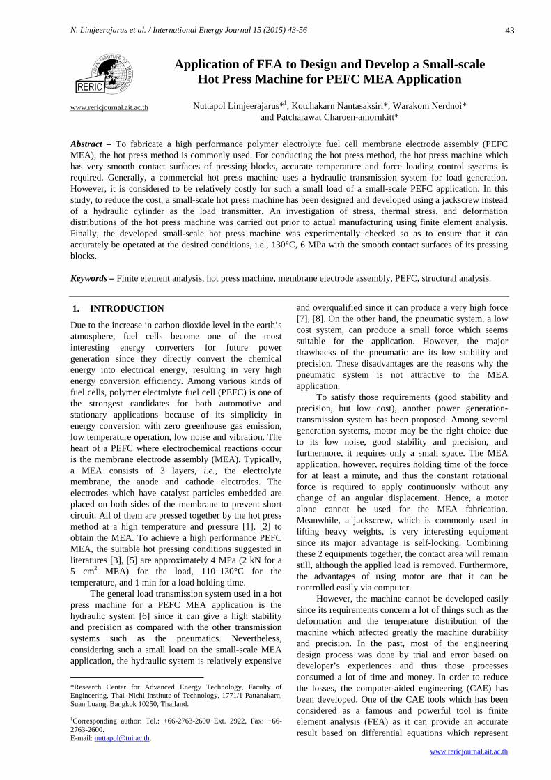
3.1 Design of the hot press machine
The design criteria of the hot press machine were that the machine must be able to produce a maximum force of 3 kN and a temperature of at least 130oC, as well as to hold at these conditions for 1 minute. For the convenience’s sake during the design process, CATIA software was used for generating the geometries, as depicted in Figure 1 (a) and (b). The systems involving in this machine consisted of 2 main systems which were 1. Force generation and transmission system and 2.Heat generation system. For the force generation and transmission system in this work, the motor was designed to be a force generator and transmitted those forces by using jackscrew. By using Equation (1), the required torque can be determined and is 2.05 N·m. As stated above, the springs were designed to be placed under the lower heating block so as to be able generate the force as a function of the displacement, and to reduce the stiffness of the heating block. Since the placing space for the springs was limited, the stiffness and the size of the springs had to be specifically selected. As the heating
block was designed to press downward, the load cell was selected by the maximum desired force and was placed under the springs. Another advantage of placing the load cell beneath the springs and the heating blocks, respectively, was that it helped reducing convection heat transfer to the load cell.
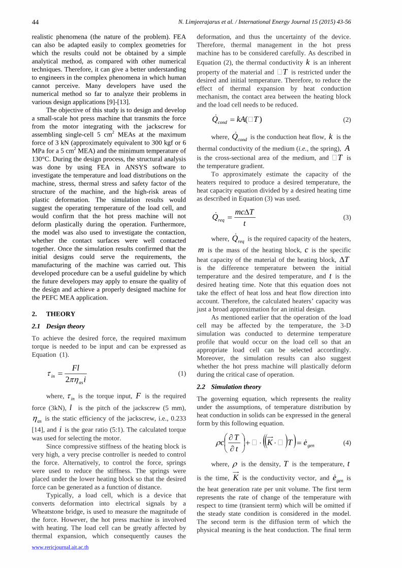
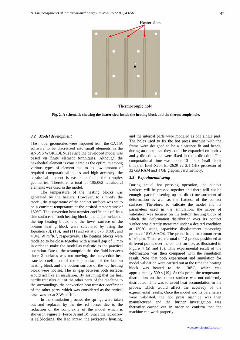
For the heat generation system, as seen in Figure 2, heat was generated by the heaters which were placed in heater slots in both top and bottom heating blocks. Since the MEA required very smooth contact surfaces (roughness < 10 µm) to avoid damaging the cell, the slots and the holes (see Figure 2) were covered by the ground contact surfaces. To measure the temperatures, thermocouples were placed at 1 mm beneath the contact surfaces in the middle of the heating blocks since they cannot be placed directly onto the contact surfaces. The thermocouples used in this work were k-type thermocouples. As the heating blocks were the areas with the highest temperature of the machine, to reduce the conduction heat flow to other parts, especially the load cell, small blocks were placed between the heating blocks and the moving plates to reduce the cross sectional area.
Fig. 1. A schematic illustration of the designed hot press machine on (a) front and (b) right side views.
N. Limjeerajarus et al. / International Energy Journal 15 (2015) 43-56
www.rericjournal.ait.ac.th
47
Fig. 2. A schematic showing the heater slots inside the heating block and the thermocouple hole.
3.2 Model development
The model geometries were imported from the CATIA software to be discretized into small elements in the ANSYS WORKBENCH since the developed model was based on finite element techniques. Although the hexahedral element is considered as the optimum among various types of element due to its low amount of required computational nodes and high accuracy, the tetrahedral element is easier to fit in the complex geometries. Therefore, a total of 185,062 tetrahedral elements was used in the model.
The temperature of the heating blocks was generated by the heaters. However, to simplify the model, the temperature of the contact surfaces was set to be a constant temperature at the desired temperature of 130°C. The convection heat transfer coefficients of the 4 side surfaces of both heating blocks, the upper surface of the top heating block, and the lower surface of the bottom heating block were calculated by using the Equation (8), (10), and (11) and set at 8.076, 8.081, and 4.041 W·m-2K-1, respectively. The heating blocks were modeled to be close together with a small gap of 1 mm in order to make the model as realistic as the practical operation. Due to the assumption that the fluid between those 2 surfaces was not moving, the convection heat transfer coefficient of the top surface of the bottom heating block and the bottom surface of the top heating block were not set. The air gap between both surfaces would act like an insulation. By assuming that the heat hardly transfers out of the other parts of the machine to the surroundings, the convection heat transfer coefficient of the other parts, which was considered as the critical case, was set at 3 W·m-2K-1.
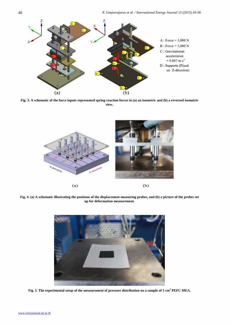
In the simulation process, the springs were taken out and replaced by the desired forces due to the reduction of the complexity of the model which is shown in Figure 3 (Force A and B). Since the jackscrew is self-locking, the lead screw, the jackscrew housing,
and the internal parts were modeled as one single part. The holes used to fix the hot press machine with the frame were designed to be a clearance fit and hence, during an operation, they could be expanded on both x and y directions but were fixed in the z direction. The computational time was about 13 hours (wall clock time), in Intel Xeon E5-2620 v2 2.1 GHz processor of 32 GB RAM and 4 GB graphic card memory.
3.3 Experimental setup
During actual hot pressing operation, the contact surfaces will be pressed together and there will not be enough space for setting up the direct measurement of deformation as well as the flatness of the contact surfaces. Therefore, to validate the model and its parameters used in the simulation, the scope of validation was focused on the bottom heating block of which the deformation distribution over its contact surface was directly measured under a desired condition at 130°C using capacitive displacement measuring probes of SYLVAC®. The probe has a maximum error of ±1 µm. There were a total of 12 probes positioned at different points over the contact surface, as illustrated in Figure 4 (a) and (b). This experimental result of the deformation was then compared with the simulation result. Note that both experiment and simulation for model validation were carried out at the time the heating block was heated to the 130°C, which was approximately 500 s [19]. At this point, the temperature distribution on the contact surface was not uniformly distributed. This was to avoid heat accumulation in the probes, which would affect the accuracy of the experimental results. Once the model and its parameters were validated, the hot press machine was then manufactured and the further investigation was thereafter carried out in order to confirm that the machine can work properly.
N. Limjeerajarus et al. / International Energy Journal 15 (2015) 43-56
www.rericjournal.ait.ac.th
48
Fig. 3. A schematic of the force inputs represented spring reaction forces in (a) an isometric and (b) a reversed isometric
view.
Fig. 4. (a) A schematic illustrating the positions of the displacement measuring probes, and (b) a picture of the probes set
up for deformation measurement.
Fig. 5. The experimental setup of the measurement of pressure distribution on a sample of 5 cm2 PEFC MEA.
N. Limjeerajarus et al. / International Energy Journal 15 (2015) 43-56
www.rericjournal.ait.ac.th
49
For the stability and precision of the force loading, the loaded force data were recorded every 10 seconds in the total time of 1 min for 10 times. Although the desired condition was to hold at 3 kN for a minute, the experiment was conducted at different forces of 1.5, 2.0, 2.5, and 3.0 kN to ensure that the machine could be operated efficiently in a wide range of forces. The flatness of the contact surfaces at the operating condition was important for the MEA fabrication since the MEA could be damaged if the pressure was not distributed uniformly. However, as there was no enough space for setting up the capacitive displacement measuring probes, an indirect approach was employed using PRESCALE® of FUJIFILM which is a pressure measurement film that indicates the pressure distribution in the variation of the red color contour. In the experiment, the PRESCALE® measurement A- and C-films were attached together and placed between the carbon papers which is one of the components of the gas diffusion layer, as shown in Figure 5. In this way, the PRESCALE® films acted as the Nafion membrane and the real hot press situation can be experimentally simulated. Thereafter, the pack of films and carbon papers was put in the center of the contact surface and pressed at the desired condition.
4. RESULTS AND DISCUSSION
4.1 Model Validation
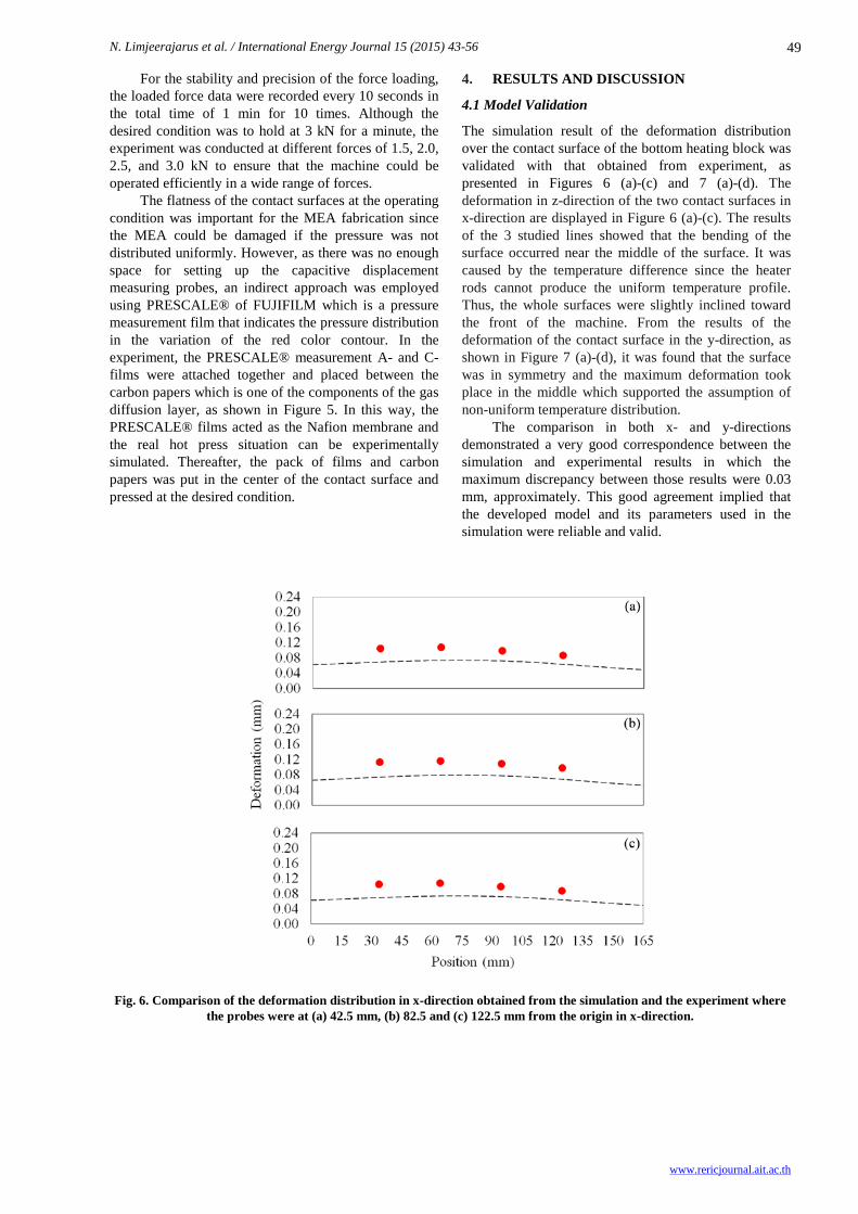
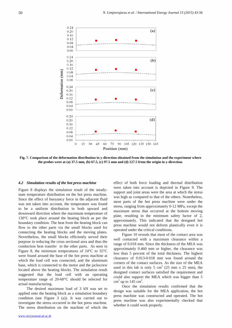
The simulation result of the deformation distribution over the contact surface of the bottom heating block was validated with that obtained from experiment, as presented in Figures 6 (a)-(c) and 7 (a)-(d). The deformation in z-direction of the two contact surfaces in x-direction are displayed in Figure 6 (a)-(c). The results of the 3 studied lines showed that the bending of the surface occurred near the middle of the surface. It was caused by the temperature difference since the heater rods cannot produce the uniform temperature profile. Thus, the whole surfaces were slightly inclined toward the front of the machine. From the results of the deformation of the contact surface in the y-direction, as shown in Figure 7 (a)-(d), it was found that the surface was in symmetry and the maximum deformation took place in the middle which supported the assumption of non-uniform temperature distribution. The comparison in both x- and y-directions demonstrated a very good correspondence between the simulation and experimental results in which the maximum discrepancy between those results were 0.03 mm, approximately. This good agreement implied that the developed model and its parameters used in the simulation were reliable and valid.
Fig. 6. Comparison of the deformation distribution in x-direction obtained from the simulation and the experiment where
the probes were at (a) 42.5 mm, (b) 82.5 and (c) 122.5 mm from the origin in x-direction.
N. Limjeerajarus et al. / International Energy Journal 15 (2015) 43-56
www.rericjournal.ait.ac.th
50
Fig. 7. Comparison of the deformation distribution in y-direction obtained from the simulation and the experiment where
the probes were at (a) 37.5 mm, (b) 67.5, (c) 97.5 mm and (d) 127.5 from the origin in y-direction.
4.2 Simulation results of the hot press machine
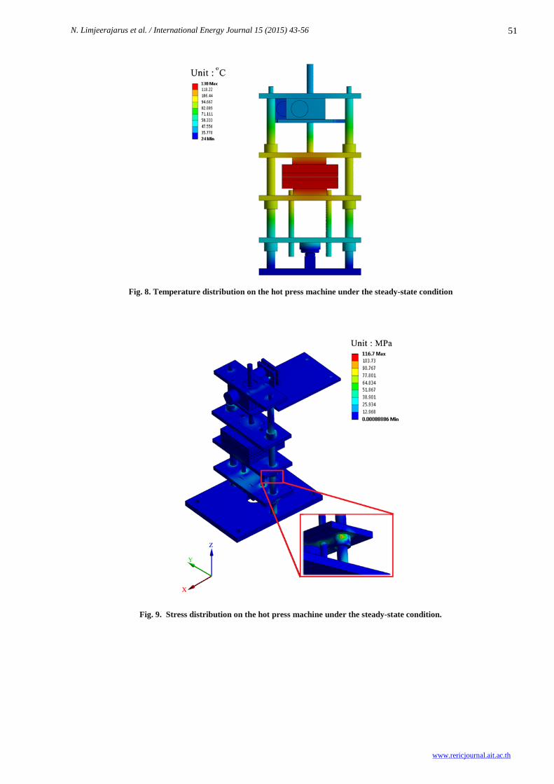
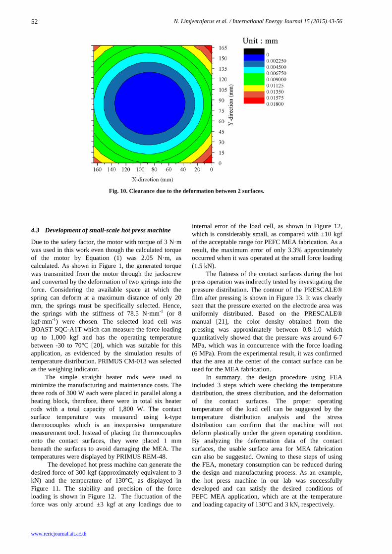
Figure 8 displays the simulation result of the steady-state temperature distribution on the hot press machine. Since the effect of buoyancy force in the adjacent fluid was not taken into account, the temperature was found to be a uniform distribution in both upward and downward direction where the maximum temperature of 130°C took place around the heating block as per the boundary condition. The heat from the heating block can flow to the other parts via the small blocks used for connecting the heating blocks and the moving plates. Nevertheless, the small blocks efficiently served their purpose in reducing the cross sectional area and thus the conduction heat transfer to the other parts. As seen in Figure 8, the minimum temperatures of 24°C to 35°C were found around the base of the hot press machine at which the load cell was connected, and the aluminum base, which is connected to the motor and the jackscrew located above the heating blocks. The simulation result suggested that the load cell with an operating temperature range of 20-60°C should be selected for actual manufacturing. The desired maximum load of 3 kN was set to applied onto the heating block as a simulation boundary condition (see Figure 3 (a)). It was carried out to investigate the stress occurred in the hot press machine. The stress distribution on the machine of which the
effect of both force loading and thermal distribution were taken into account is depicted in Figure 9. The support and joint areas were the area at which the stress was high as compared to that of the others. Nonetheless, most parts of the hot press machine were under the stress, ranging from approximately 0-12 MPa, except the maximum stress that occurred at the bottom moving plate, resulting in the minimum safety factor of 2, approximately. This indicated that the designed hot press machine would not deform plastically even it is operated under the critical conditions.
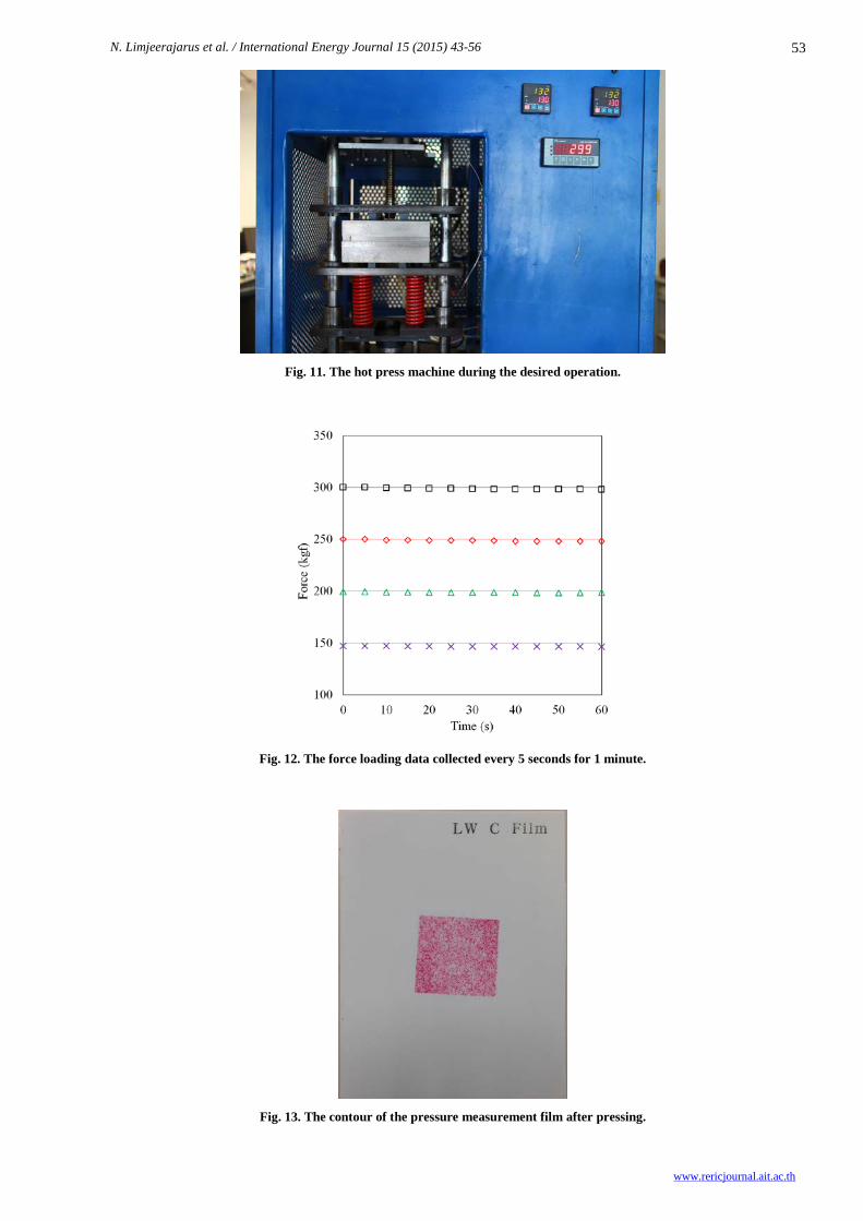
Figure 10 reveals that most of the contact area was well contacted with a maximum clearance within a range of 0.018 mm. Since the thickness of the MEA was approximately 0.460 mm or higher, the clearance was less than 5 percent of the total thickness. The highest clearance of 0.013-0.018 mm was found around the corners of the contact surfaces. As the size of the MEA used in this lab is only 5 cm2 (25 mm x 25 mm), the designed contact surfaces satisfied the requirement and could also support the MEA which was bigger than 5 cm2 up to 145 cm2.
Once the simulation results confirmed that the design was suitable for the MEA application, the hot press machine was constructed and operated. The hot press machine was also experimentally checked that whether it could work properly.
N. Limjeerajarus et al. / International Energy Journal 15 (2015) 43-56
www.rericjournal.ait.ac.th
51
Fig. 8. Temperature distribution on the hot press machine under the steady-state condition
Fig. 9. Stress distribution on the hot press machine under the steady-state condition.
N. Limjeerajarus et al. / International Energy Journal 15 (2015) 43-56
www.rericjournal.ait.ac.th
52
Fig. 10. Clearance due to the deformation between 2 surfaces.
4.3 Development of small-scale hot press machine
Due to the safety factor, the motor with torque of 3 N·m was used in this work even though the calculated torque of the motor by Equation (1) was 2.05 N·m, as calculated. As shown in Figure 1, the generated torque was transmitted from the motor through the jackscrew and converted by the deformation of two springs into the force. Considering the available space at which the spring can deform at a maximum distance of only 20 mm, the springs must be specifically selected. Hence, the springs with the stiffness of 78.5 N·mm-1 (or 8 kgf·mm-1) were chosen. The selected load cell was BOAST SQC-A1T which can measure the force loading up to 1,000 kgf and has the operating temperature between -30 to 70°C [20], which was suitable for this application, as evidenced by the simulation results of temperature distribution. PRIMUS CM-013 was selected as the weighing indicator. The simple straight heater rods were used to minimize the manufacturing and maintenance costs. The three rods of 300 W each were placed in parallel along a heating block, therefore, there were in total six heater rods with a total capacity of 1,800 W. The contact surface temperature was measured using k-type thermocouples which is an inexpensive temperature measurement tool. Instead of placing the thermocouples onto the contact surfaces, they were placed 1 mm beneath the surfaces to avoid damaging the MEA. The temperatures were displayed by PRIMUS REM-48.
The developed hot press machine can generate the desired force of 300 kgf (approximately equivalent to 3 kN) and the temperature of 130°C, as displayed in Figure 11. The stability and precision of the force loading is shown in Figure 12. The fluctuation of the force was only around ±3 kgf at any loadings due to
internal error of the load cell, as shown in Figure 12, which is considerably small, as compared with ±10 kgf of the acceptable range for PEFC MEA fabrication. As a result, the maximum error of only 3.3% approximately occurred when it was operated at the small force loading (1.5 kN). The flatness of the contact surfaces during the hot press operation was indirectly tested by investigating the pressure distribution. The contour of the PRESCALE® film after pressing is shown in Figure 13. It was clearly seen that the pressure exerted on the electrode area was uniformly distributed. Based on the PRESCALE® manual [21], the color density obtained from the pressing was approximately between 0.8-1.0 which quantitatively showed that the pressure was around 6-7 MPa, which was in concurrence with the force loading (6 MPa). From the experimental result, it was confirmed that the area at the center of the contact surface can be used for the MEA fabrication. In summary, the design procedure using FEA included 3 steps which were checking the temperature distribution, the stress distribution, and the deformation of the contact surfaces. The proper operating temperature of the load cell can be suggested by the temperature distribution analysis and the stress distribution can confirm that the machine will not deform plastically under the given operating condition. By analyzing the deformation data of the contact surfaces, the usable surface area for MEA fabrication can also be suggested. Owning to these steps of using the FEA, monetary consumption can be reduced during the design and manufacturing process. As an example, the hot press machine in our lab was successfully developed and can satisfy the desired conditions of PEFC MEA application, which are at the temperature and loading capacity of 130°C and 3 kN, respectively.
N. Limjeerajarus et al. / International Energy Journal 15 (2015) 43-56
www.rericjournal.ait.ac.th
53
Fig. 11. The hot press machine during the desired operation.
Fig. 12. The force loading data collected every 5 seconds for 1 minute.
Fig. 13. The contour of the pressure measurement film after pressing.
N. Limjeerajarus et. al/ International Energy Journal 15 (2015) 43-56
www.rericjournal.ait.ac.th
54
5. CONCLUSION
FEA was applied to design and develop a small-scale hot press machine during designing section. It was carried out to investigate the temperature distribution at the load cell placing area so that a proper load cell can be selected. The stress occurred due to the thermal and force loads were also studied to ensure that the machine would not deform plastically during a critical case operation. As per PEFC MEA application requirement, the designed machine can generate the desired force of 3 kN, the temperature of 130°C, and hold the load for 1 min. The experimental result of the pressure distribution was in concurrence with the result of the 3-D simulation of which the center area of the contact surface was well contacted and suitable for MEA fabrication. Furthermore, the procedure proposed in this study can be used as a guideline for the design of a small-scale hot press machine.
ACKNOWLEDGEMENT
The authors would like to acknowledge the research fund provided by Thai-Nichi Institute of Technology under the project ID: 1410/A008.
NOMENCLATURE
A cross-sectional area, m2
c specific heat capacity, J·kg-1K-1
][E elastic stiffness matrix
gene heat generation rate per unit volume, W·m-3
F required force, N g gravitational acceleration, m·s-2
LGr Grashof number
fh convection heat transfer coefficient, W·m-2K-1 k thermal conductivity, W·m-1K-1
K conductivity vector
fk thermal conductivity of adjacent fluid, W·m-
1·K-1
cL characteristic length, m m mass, kg Nu Nusselt number Pr Prandtl number
Q conduction heat flow, W
LQ heat loss, W
LRa Rayleigh number t time, s
BT bulk temperature of adjacent fluid, °C
sT surface temperature, °C TΔ temperature difference, °C
Greek letters α coefficient of thermal expansion, K-1 β coefficient of volume expansion, m3·m-3°C-1
thε thermal normal strain
}{ε total strain vector
asη static efficiency ρ density, kg·m-3 { }σ stress vector, Pa
inτ torque input, N·m ν kinematic viscosity of adjacent fluid, m2·s-1
REFERENCES
[1] Therdthianwong A., Manomayidthikarn P. and Therdthianwong S., 2007. Investigation of membrane electrode assembly (MEA) hot-pressing parameters for proton exchange membrane fuel cell. Energy 32(12): 2401 – 2411.
[2] Limjeerajarus N., Yanagimoto T., Yamamoto T., Ito T. and Yamaguchi T., 2008. Quantitative analysis of oxygen-containing species adsorbed on the Pt surface of a polymer electrolyte fuel cell membrane electrode assembly electrode using stripping voltammetry. Journal of power sources 185: 217-221.
[3] Hasran U.A., Kamarudin S.K., Daud W.R.W, Majlis B.Y., Mohamad A.B., Kadhum A.A.H. and Ahmad M.M., 2003. Optimization of hot pressing parameters in membrane electrode assembly fabrication by response surface method. Hydrogen Energy 38(22): 9484-9493.
[4] Larminie J. and A. Dicks. 2003. Fuel cell systems explained. UK: John Wiley & Sons.
[5] Limjeerajarus N., Nichiyama Y., Ohashi H. and Yamaguchi T., 2009. Modeling for PEFC MEAs based on reaction rate on Pt surface and microstructures of catalyst layers. Journal of Chemical Engineering of Japan 42(8): 616-631.
[6] Elias K.Q. and H.K. Kurek. Principles of High Performance Membrane Electrode Assembly Fabrication. Worcester Polytechnic Institute. Retrieved May 14, 2014 from the World Wide Web:http://www.wpi.edu/Pubs/E-project/Available/E-project-042607104439/unrestricted/MQP_RYD2007_qke_katk.pdf.
[7] Carver Laboratory Presses and Accessories, Carver 100th Anniversary 1912-2012: Laboratory Presses and Accessories. Carver, Inc. Retrieved May 14, 2014 from the World Wide Web: http://www.carverpress.com/pdfs/Ccatalog.pdf.
[8] Carver Hydraulic Presses & Accessories, Caver 2011 Price book. Carver, Inc. Retrieved May 14, 2014 from the World Wide Web: http://ep.yimg.com/ty/cdn/eeffppkk/2011-CarverPrice-List.pdf.
[9] Limjeerajarus N. and P. Charoen-amornkitt. 2015. Effect of different flow field designs and number of channels on performance of a small PEFC. International Journal of Hydrogen Energy. 40(22): 7144-7158.
[10] Croccolo D., Cuppini R., and Vincenzi N., 2007. The design and optimization of fork–pin compression coupling in front motorbike
N. Limjeerajarus et. al/ International Energy Journal 15 (2015) 43-56
55
www.rericjournal.ait.ac.th
suspensions. Finite Elements in Analysis and Design 43: 977-988.
[11] Croccolo D., Cuppini R. and Vincenzi N., 2009. Design improvement of clamped joints in front motorbike suspension based on FEM analysis. Finite Elements in Analysis and Design 45: 406-414.
[12] Zhu W., Wang J., and Lin P., 2014. Numerical analysis and optimal design for new automotive door sealing with variable cross-section. Finite Elements in Analysis and Design 91: 115-126.
[13] Biboulet N., Gravouil A., Dureisseix D., Lubrecht A.A. and Combescure A., 2013. An efficient linear elastic FEM solver using automatic local grid refinement and accuracy control. Finite Elements in Analysis and Design 68: 28-38.
[14] Power Jack, Power Jacks Linear Motion and Power Transmission Design Guide - Section 1 - Screw Jacks (Mechanical Actuators). Power Jacks ltd. Retrieved May 15, 2014 from the World Wide Web: http://www.powerjacks.com/downloads/Design%20Guides/PJLMPT-02/S1-Screw-Jacks-PJLMPTDG02.pdf
[15] Cengel Y.A. and A.J. Ghajar. 2011. Heat and Mass Transfer: Fundamentals and Applications. Singapore: McGraw – Hill.
[16] Churchill S.W. and H.H.S. Chu. 1975. Correlating equations for laminar and turbulent free convection from a vertical plate. International Journal of Heat Mass transfer 18(11): 1323 - 1329.
[17] Bundynas G.R. and K.J. Nisbett. 2008. Shigley’s Mechanical Engineering Design. Singapore: McGraw – Hill.
[18] ANSYS Inc., 2009. Theory Reference for the Mechanical APDL and Mechanical Applications. South pointe: ANSYS, Inc.
[19] Chaithanee N., Charoen-amornkitt P., Nantasaksiri K. and Limjeerajarus N., 2014. A 3-D numerical simulation of temperature distribution across the contact surface of a small-scale hot press machine for PEFC applications. In Proceedings of the 5th TSME International Conference on Mechanical Engineering, Chiang Mai, Thailand 17-19 December.
[20] BOAST, SQC-A Product details. Ningbo BOARD Electric Co., Ltd. Retrieved May 15, 2014 from the World Wide Web: http://www.nbboard.com/EN/Products_View.asp?ProId=49.
[21] FUJIFILM, PRESCALE Instruction sheet. FUJIFILM. Retrieved June 25, 2015 from the World Wide Web: http://www.spare.it/prescale-letteratura/Prescale-LW-manual.pdf.

N. Limjeerajarus et. al/ International Energy Journal 15 (2015) 43-56
www.rericjournal.ait.ac.th
56