Embed Size (px)
Citation preview
Application of GPS/GNSS in Cybermapping
Cybermapping LabUniversity of Texas at Dallas
2009
GNSSGNSS
• Global Navigation Satellite System (GNSSGNSS) is the standard generic term for satellite navigation systems that provide autonomous geo-spatial positioning with global coverage.
• A GNSS allows small electronic receivers to determine their location (longitude, latitude, and altitude) using time signals transmitted along a line of sight by radio from satellites.
• Receivers on the ground with a fixed position can also be used to calculate the precise time as a reference for scientific experiments.
• The Russian GLONASS is a GNSS in the process of being restored to full operation.
• The European Union's Galileo positioning system is a next generation GNSS in the initial deployment phase, scheduled to be operational in 2013.
• China has indicated it may expand its regional Beidou navigation system into a global system.
• India's IRNSSIRNSS, a next generation GNSS is in developmental phase and is scheduled to be operational around 2012.
•• 3G3G : : Galileo, GLONASS, and GPSGalileo, GLONASS, and GPS
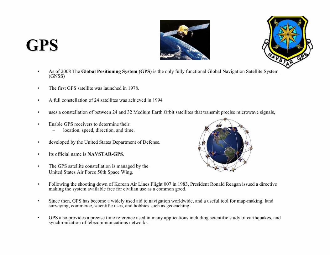
GPSGPS• As of 2008 The Global Positioning System (GPS) is the only fully functional Global Navigation Satellite System
(GNSS)
• The first GPS satellite was launched in 1978.
• A full constellation of 24 satellites was achieved in 1994
• uses a constellation of between 24 and 32 Medium Earth Orbit satellites that transmit precise microwave signals,
• Enable GPS receivers to determine their:– location, speed, direction, and time.
• developed by the United States Department of Defense.
• Its official name is NAVSTAR-GPS.
• The GPS satellite constellation is managed by the United States Air Force 50th Space Wing.
• Following the shooting down of Korean Air Lines Flight 007 in 1983, President Ronald Reagan issued a directive making the system available free for civilian use as a common good.
• Since then, GPS has become a widely used aid to navigation worldwide, and a useful tool for map-making, land surveying, commerce, scientific uses, and hobbies such as geocaching.
• GPS also provides a precise time reference used in many applications including scientific study of earthquakes, and synchronization of telecommunications networks.
GLONASSGLONASS
• GLONASS - GLObal'naya NAvigatsionnaya Sputnikovaya Sistema developed by the former Soviet Union
• Now operated for the Russian government by the Russian Space Forces.
• Development on the GLONASS began in 1976, with a goal of global coverage by 1991.
• Beginning on 12 October 1982, numerous rocket launches added satellites to the system until the constellation was completed in 1995.
• Following completion, the system rapidly fell into disrepair with the collapse of the Russian economy.
• Beginning in 2001, Russia committed to restoring the system, and in recent years has diversified,
• Introducing the Indian government as a partner, and accelerated the program with a goal of restoring global coverage by 2009

GALILEOGALILEO• Named for the Italian astronomer Galileo Galilei, the positioning system is officially referred to as just "Galileo".
• It is also sometimes described as the "Galileo Positioning System"; however, since this abbreviates to GPS, the shorter name is preferred to avoid confusion with the U.S. GPS.
• Galileo is currently being built by the European Union (EU) and European Space Agency (ESA).
• The €3.4 billion project is an alternative and complementary to the (GPS) and the GLONASS.
• On November 30, 2007 the 27 EU transportation ministers involved reached an agreement that it should be operational by 2013.
• When in operation, it will have two ground operations centers, one near Munich, Germany, and another in Fucino, 130 km east of Rome, Italy.
• Since 18 May 2007, at the recommendation of Transport Commissioner Jacques Barrot, the EU took direct control of the Galileo project from the private sector group of eight companies called European Satellite Navigation Industries, which had abandoned this Galileo project in early 2007.
• Galileo is intended to provide more precise measurements than available through GPS or GLONASS, better positioning services at high latitudes and an independent positioning system upon which European nations can rely even in times of war or political disagreement, since Russia or the USA could disable use by others (through encryption).
• Like GPS, use will also be free for everyone.
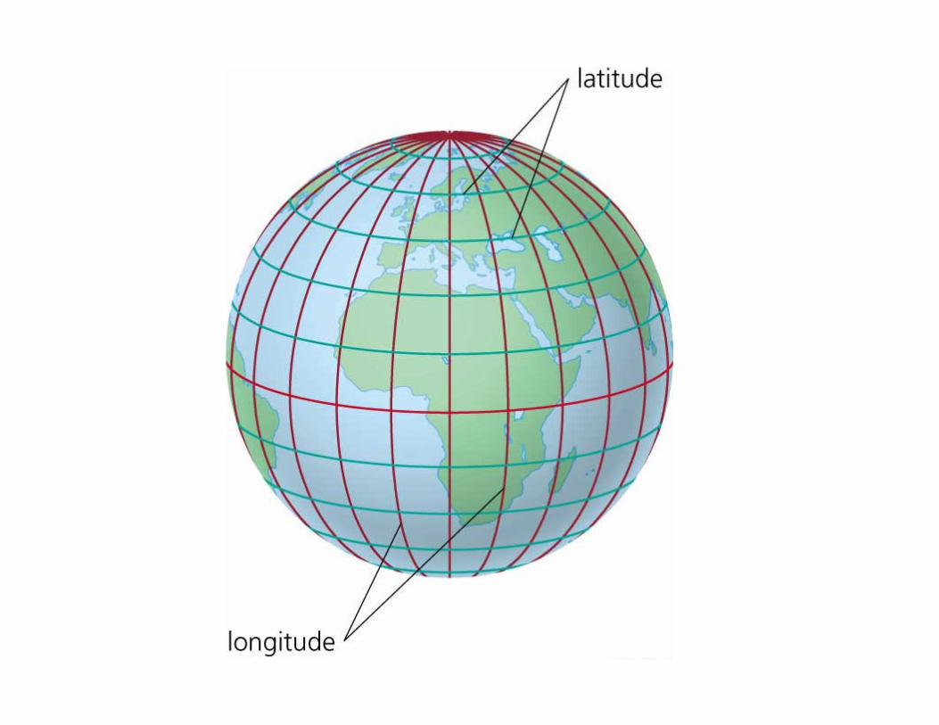
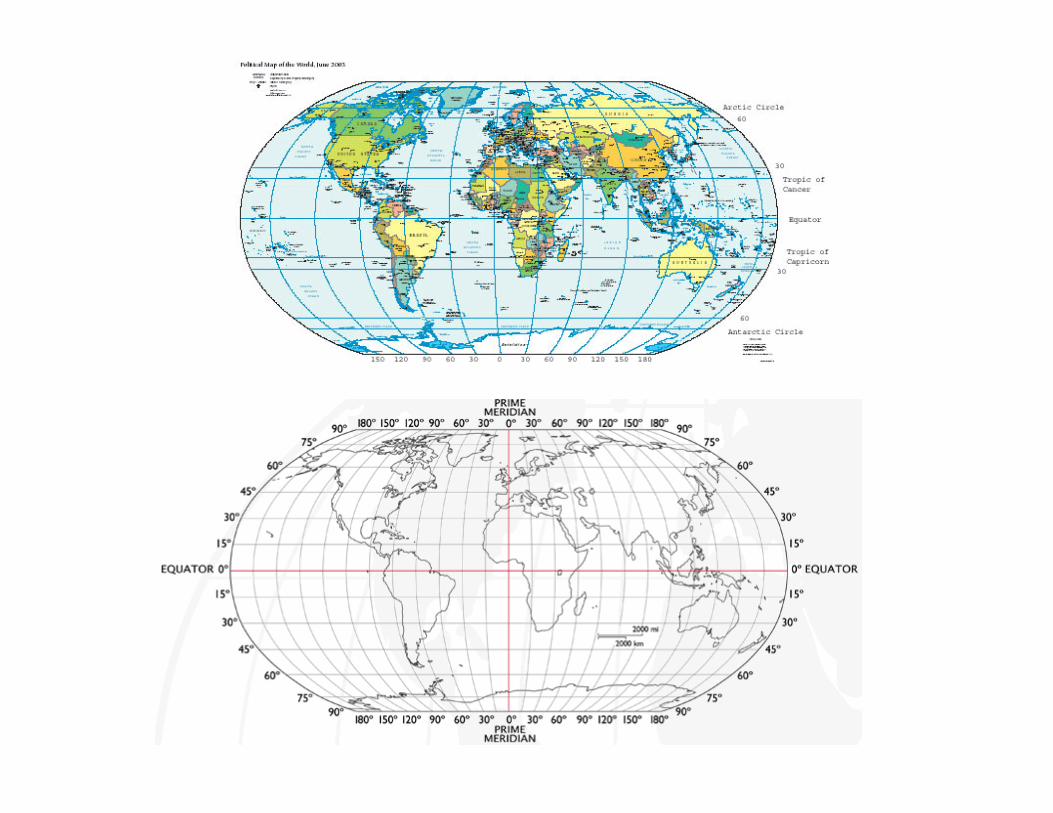
Longitude, Latitude, AltitudeLongitude, Latitude, Altitude• Longitude mostly symbolized by lambda (λ), is the east-west geographic
coordinate measurement most commonly used in cartography and global navigation. A line of longitude is a meridian and half of a great circle.
• Latitude, mostly symbolized by lambda phi (Φ), gives the location of a place onEarth north or south of the equator. Lines of Latitude are the horizontal lines shown running east-to-west on maps. Technically, latitude is an angular measurement in degrees (marked with °) ranging from 0° at the equator (low latitude) to 90° at the poles (90° N for the North Pole or 90° S for the South Pole; high latitude). The complementary angle of a latitude is called the colatitude.
• Altitude is the elevation of a point or object from a known level or datum. Common data are mean sea level, local ground level (Above Ground Level, or AGL), or the surface of the WGS-84 geoid, used by GPS. In aviation, altitude is measured in feet. For non-aviation uses, altitude may be measured in other units such as metres or miles.
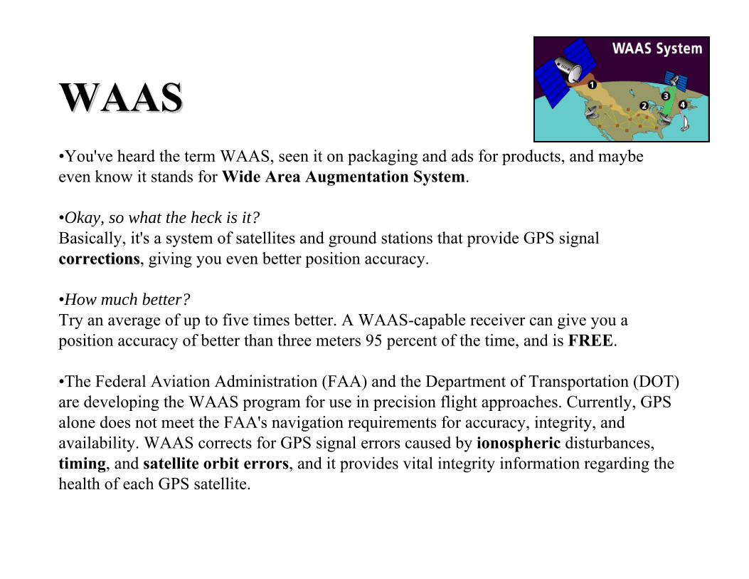
WAASWAAS•You've heard the term WAAS, seen it on packaging and ads for products, and maybe even know it stands for Wide Area Augmentation System.
•Okay, so what the heck is it?Basically, it's a system of satellites and ground stations that provide GPS signal correctionscorrections, giving you even better position accuracy.
•How much better?Try an average of up to five times better. A WAAS-capable receiver can give you a position accuracy of better than three meters 95 percent of the time, and is FREE.
•The Federal Aviation Administration (FAA) and the Department of Transportation (DOT) are developing the WAAS program for use in precision flight approaches. Currently, GPS alone does not meet the FAA's navigation requirements for accuracy, integrity, and availability. WAAS corrects for GPS signal errors caused by ionospheric disturbances, timing, and satellite orbit errors, and it provides vital integrity information regarding the health of each GPS satellite.
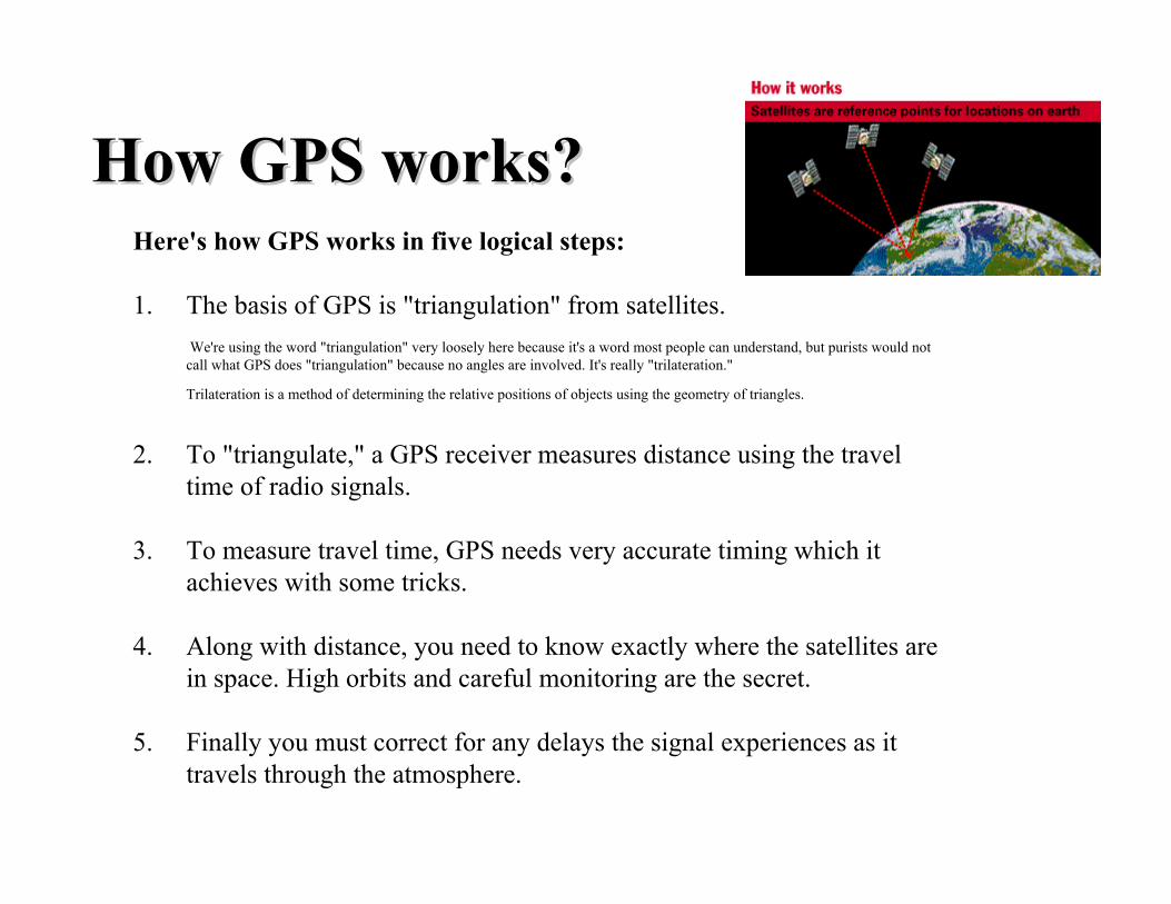
How GPS works?How GPS works?Here's how GPS works in five logical steps:
1. The basis of GPS is "triangulation" from satellites.We're using the word "triangulation" very loosely here because it's a word most people can understand, but purists would not
call what GPS does "triangulation" because no angles are involved. It's really "trilateration."
Trilateration is a method of determining the relative positions of objects using the geometry of triangles.
2. To "triangulate," a GPS receiver measures distance using the travel time of radio signals.
3. To measure travel time, GPS needs very accurate timing which it achieves with some tricks.
4. Along with distance, you need to know exactly where the satellites are in space. High orbits and careful monitoring are the secret.
5. Finally you must correct for any delays the signal experiences as it travels through the atmosphere.
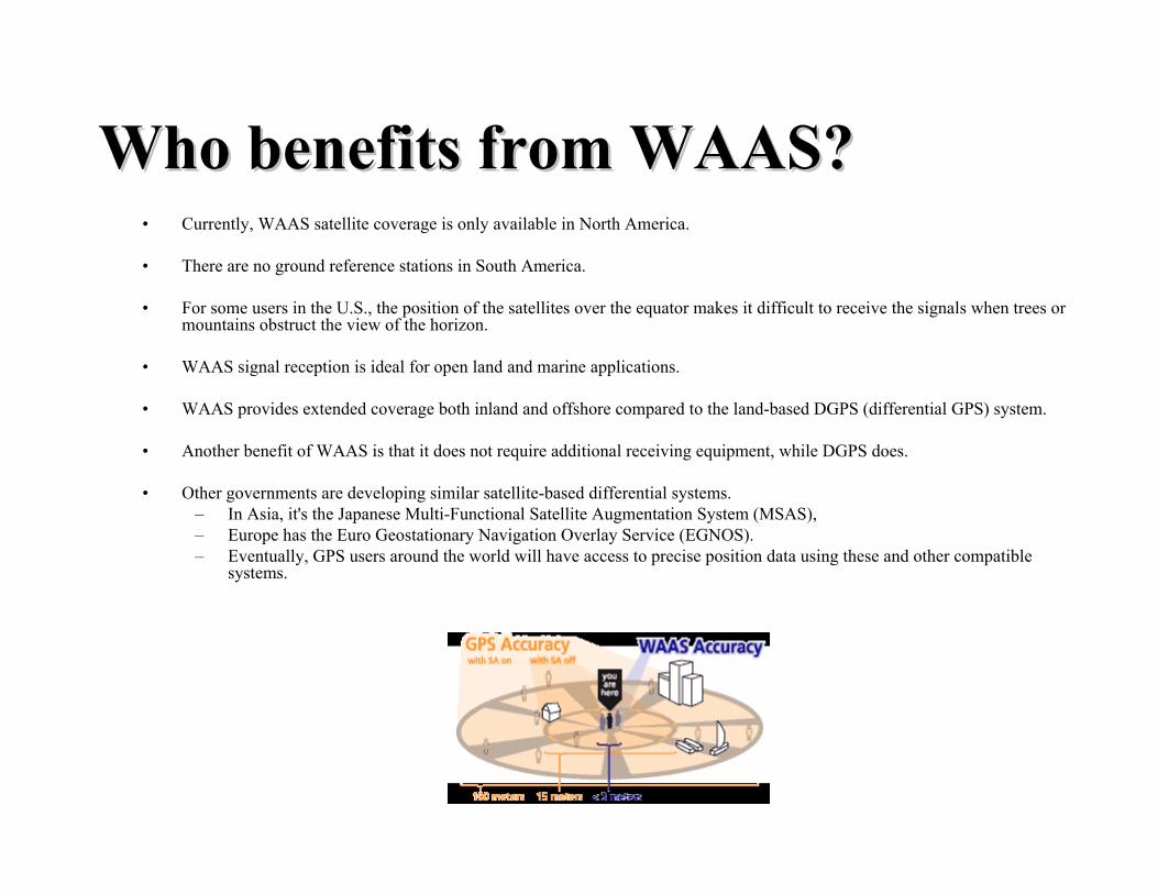
Who benefits from WAAS?Who benefits from WAAS?• Currently, WAAS satellite coverage is only available in North America.
• There are no ground reference stations in South America.
• For some users in the U.S., the position of the satellites over the equator makes it difficult to receive the signals when trees or mountains obstruct the view of the horizon.
• WAAS signal reception is ideal for open land and marine applications.
• WAAS provides extended coverage both inland and offshore compared to the land-based DGPS (differential GPS) system.
• Another benefit of WAAS is that it does not require additional receiving equipment, while DGPS does.
• Other governments are developing similar satellite-based differential systems. – In Asia, it's the Japanese Multi-Functional Satellite Augmentation System (MSAS),– Europe has the Euro Geostationary Navigation Overlay Service (EGNOS).– Eventually, GPS users around the world will have access to precise position data using these and other compatible
systems.
ACRONYMS US
NATIONAL SPATIAL REFERENCE SYSTEM
The National Spatial Reference System (NSRS) is that component of the National Spatial Data Infrastructure (NSDI) - [http://www.fgdc.gov/nsdi/nsdi.html] which contains all geodetic control contained in the National Geodetic Survey (NGS) Data Base. This includes: A, B, First, Second and Third-Order horizontal and vertical control, Geoid models such as GEOID 99, precise GPS orbits and Continuously Operating Reference Stations (CORS), and the National Shoreline as observed by NGS as well as data submitted by other Federal, State, and local agencies, Academic Institutions and the private sector
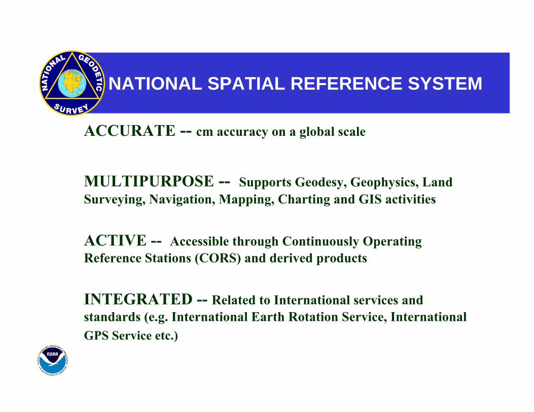
NATIONAL SPATIAL REFERENCE SYSTEM
ACCURATE -- cm accuracy on a global scale
MULTIPURPOSE -- Supports Geodesy, Geophysics, Land Surveying, Navigation, Mapping, Charting and GIS activities
ACTIVE -- Accessible through Continuously Operating Reference Stations (CORS) and derived products
INTEGRATED -- Related to International services and standards (e.g. International Earth Rotation Service, International
GPS Service etc.)
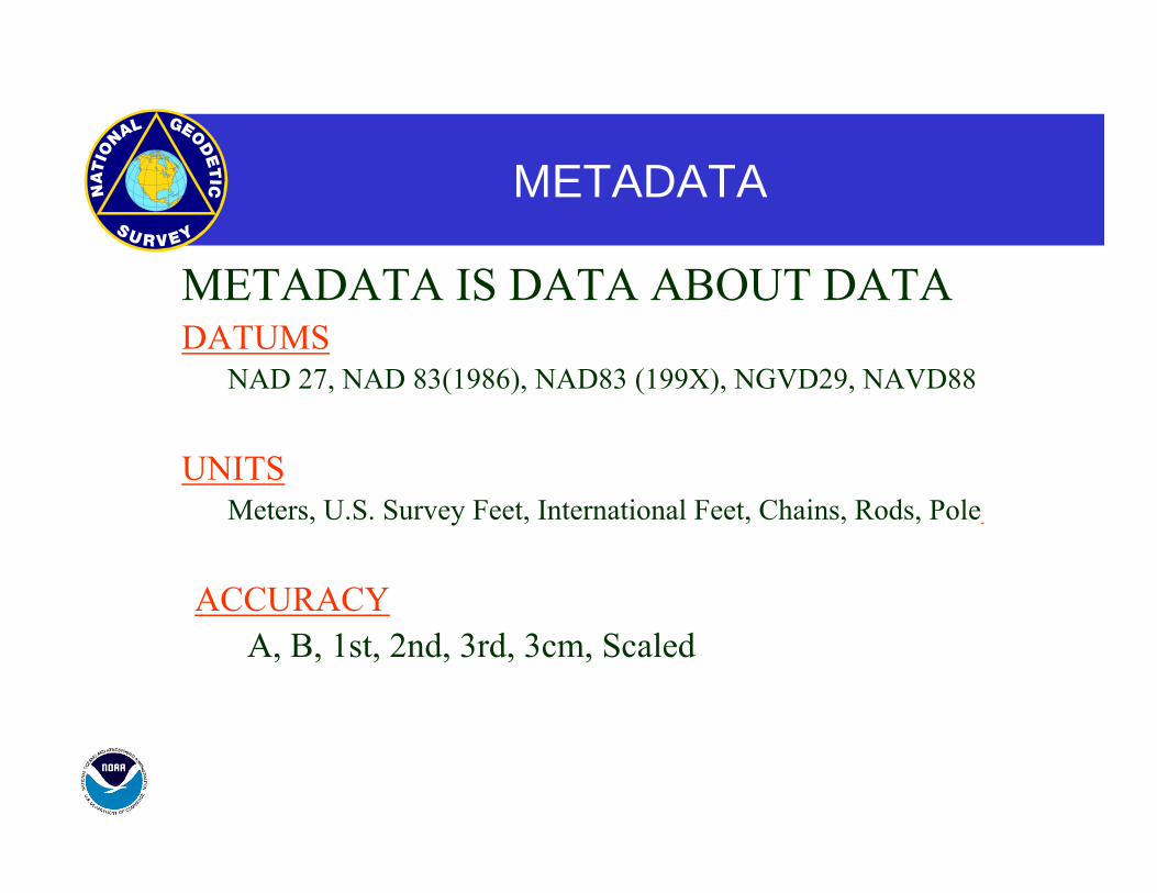
METADATA
METADATA IS DATA ABOUT DATA DATUMS
NAD 27, NAD 83(1986), NAD83 (199X), NGVD29, NAVD88
UNITS Meters, U.S. Survey Feet, International Feet, Chains, Rods, Pole
ACCURACY A, B, 1st, 2nd, 3rd, 3cm, Scaled
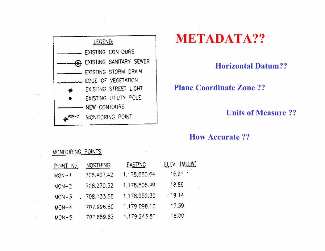
METADATA??
Horizontal Datum??
Plane Coordinate Zone ??
Units of Measure ??
How Accurate ??
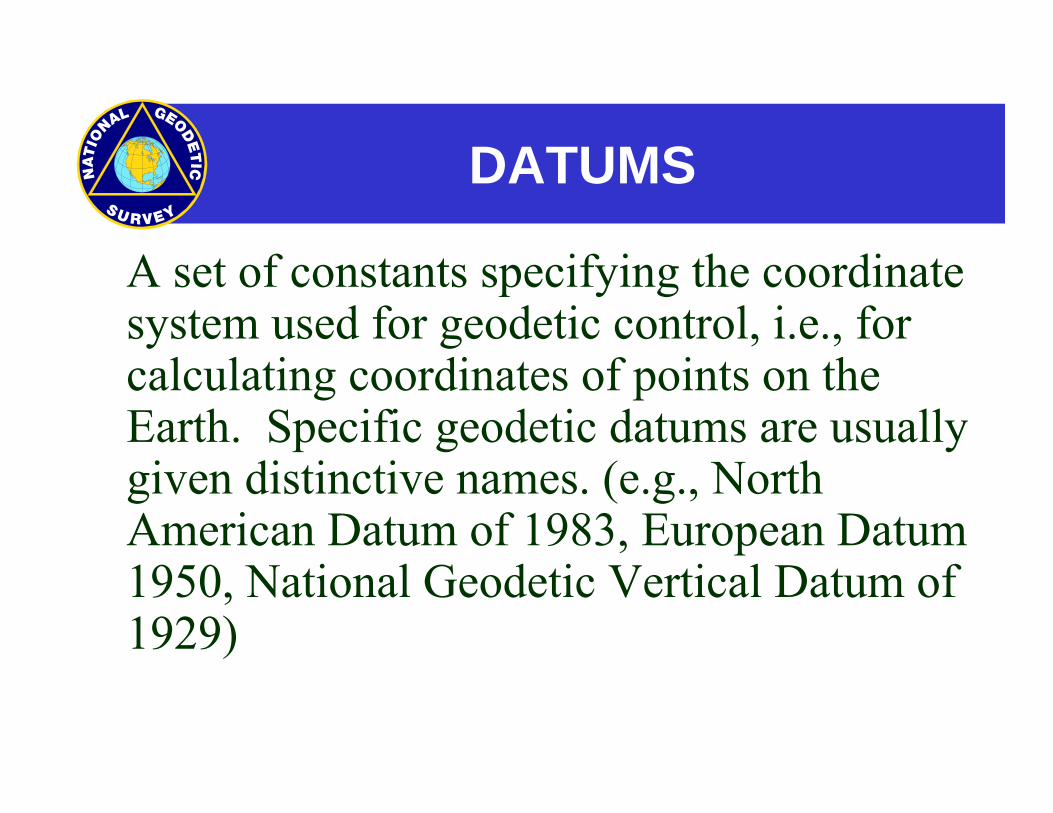
DATUMS
A set of constants specifying the coordinate system used for geodetic control, i.e., for calculating coordinates of points on the Earth. Specific geodetic datums are usually given distinctive names. (e.g., North American Datum of 1983, European Datum 1950, National Geodetic Vertical Datum of 1929)
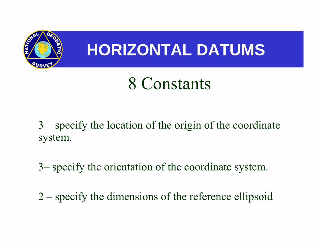
HORIZONTAL DATUMS
8 Constants
3 – specify the location of the origin of the coordinate system.
3– specify the orientation of the coordinate system.
2 – specify the dimensions of the reference ellipsoid
VERTICAL DATUMS
A set of fundamental elevations to which other elevations are referred.
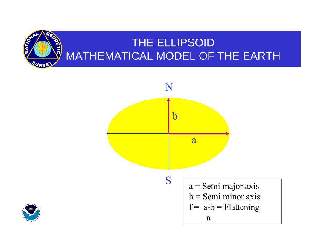
THE ELLIPSOIDMATHEMATICAL MODEL OF THE EARTH
b
a
a = Semi major axisb = Semi minor axisf = a-b = Flattening
a
N
S
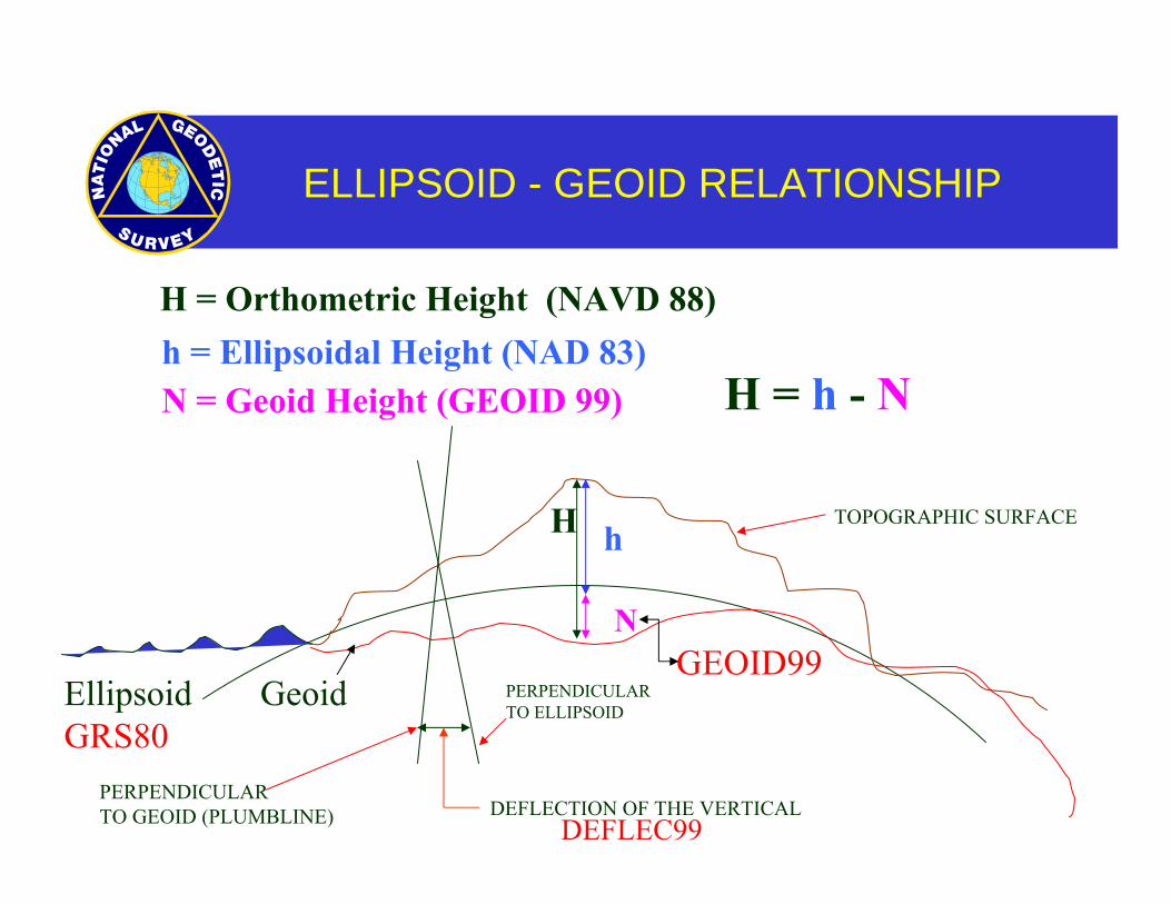
ELLIPSOID - GEOID RELATIONSHIP
H h
EllipsoidGRS80
H = Orthometric Height (NAVD 88)
N
Geoid
H = h - N
PERPENDICULAR TO ELLIPSOID
PERPENDICULARTO GEOID (PLUMBLINE) DEFLECTION OF THE VERTICAL
DEFLEC99
TOPOGRAPHIC SURFACE
h = Ellipsoidal Height (NAD 83)N = Geoid Height (GEOID 99)
GEOID99
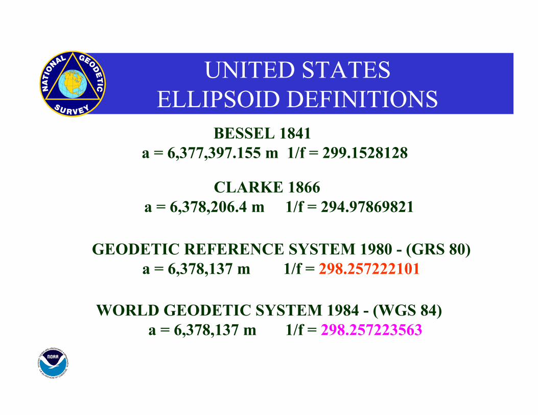
UNITED STATESELLIPSOID DEFINITIONS
CLARKE 1866a = 6,378,206.4 m 1/f = 294.97869821
GEODETIC REFERENCE SYSTEM 1980 - (GRS 80)a = 6,378,137 m 1/f = 298.257222101
WORLD GEODETIC SYSTEM 1984 - (WGS 84)a = 6,378,137 m 1/f = 298.257223563
BESSEL 1841a = 6,377,397.155 m 1/f = 299.1528128
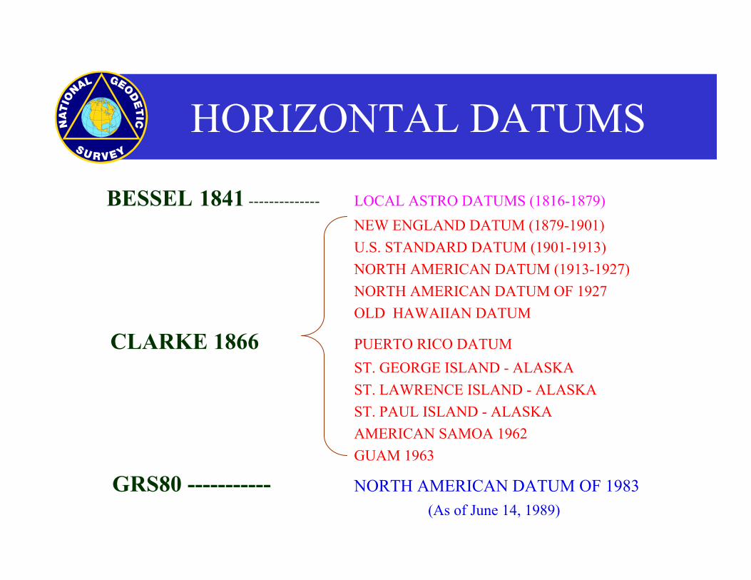
HORIZONTAL DATUMS
BESSEL 1841 -------------- LOCAL ASTRO DATUMS (1816-1879) NEW ENGLAND DATUM (1879-1901) U.S. STANDARD DATUM (1901-1913) NORTH AMERICAN DATUM (1913-1927) NORTH AMERICAN DATUM OF 1927 OLD HAWAIIAN DATUM
CLARKE 1866 PUERTO RICO DATUM ST. GEORGE ISLAND - ALASKA ST. LAWRENCE ISLAND - ALASKA ST. PAUL ISLAND - ALASKA AMERICAN SAMOA 1962 GUAM 1963
GRS80 ----------- NORTH AMERICAN DATUM OF 1983 (As of June 14, 1989)
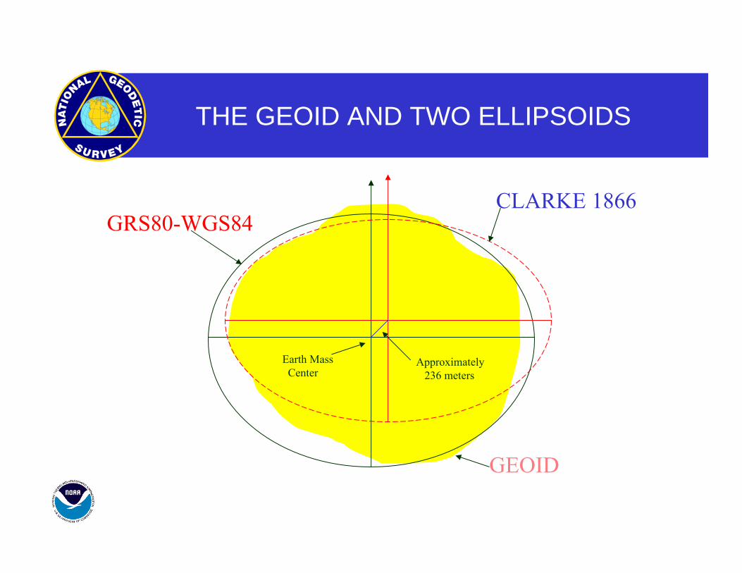
THE GEOID AND TWO ELLIPSOIDS
GRS80-WGS84
CLARKE 1866
GEOID
Earth MassCenter
Approximately236 meters
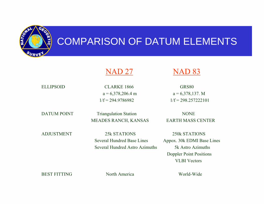
COMPARISON OF DATUM ELEMENTS
NAD 27 NAD 83
ELLIPSOID CLARKE 1866 GRS80 a = 6,378,206.4 m a = 6,378,137. M 1/f = 294.9786982 1/f = 298.257222101
DATUM POINT Triangulation Station NONE MEADES RANCH, KANSAS EARTH MASS CENTER
ADJUSTMENT 25k STATIONS 250k STATIONS Several Hundred Base Lines Appox. 30k EDMI Base Lines Several Hundred Astro Azimuths 5k Astro Azimuths Doppler Point Positions VLBI Vectors
BEST FITTING North America World-Wide
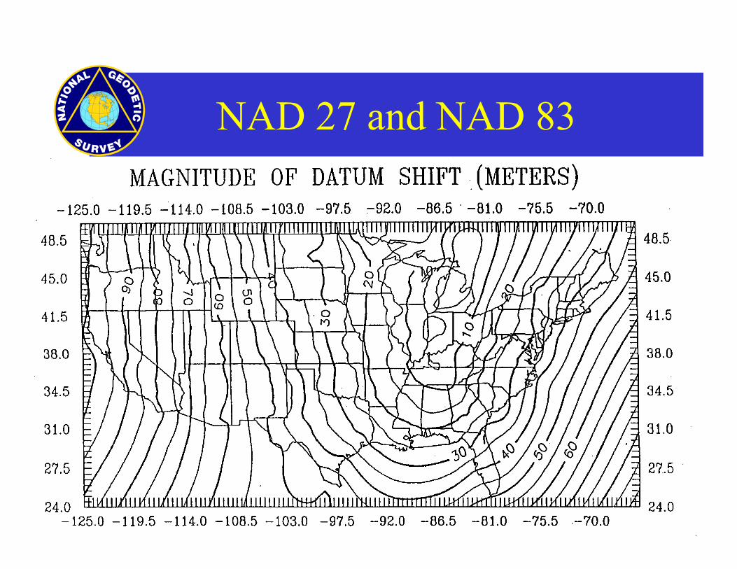
NAD 27 and NAD 83
NAD 83 NETWORK PROBLEMS
NOT “GPSABLE”
POOR STATION ACCESSIBILITY
IRREGULARLY SPACED
POSITIONAL ACCURACY
HIGH ACCURACY REFERENCE NETWORKS
“GPSABLE” Clear Horizons for Satellite Signal Acquisition
EASY ACCESSIBILITY Few Special Vehicle or Property Entrance Requirements
REGULARLY SPACED Always within 20-100 Km
HIGH HORIZONTAL ACCURACY A-Order (5 mm + 1:10,000,000) B-Order (8mm + 1:1,000,000)
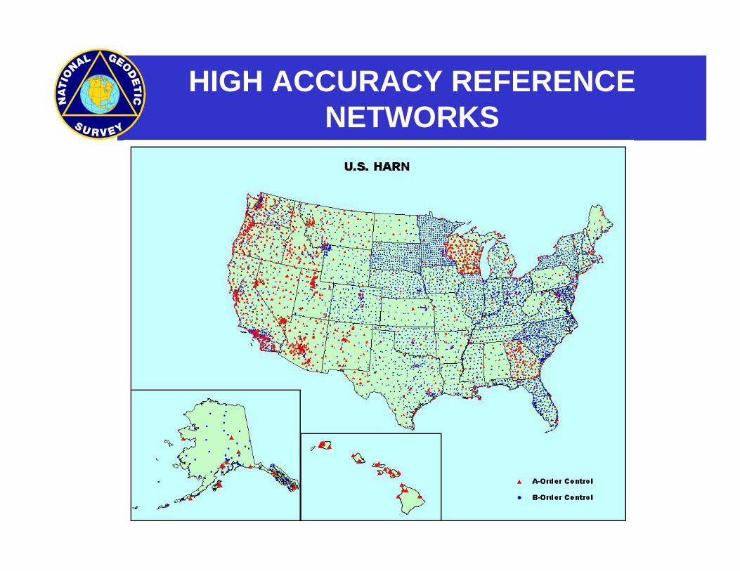
HIGH ACCURACY REFERENCE NETWORKS
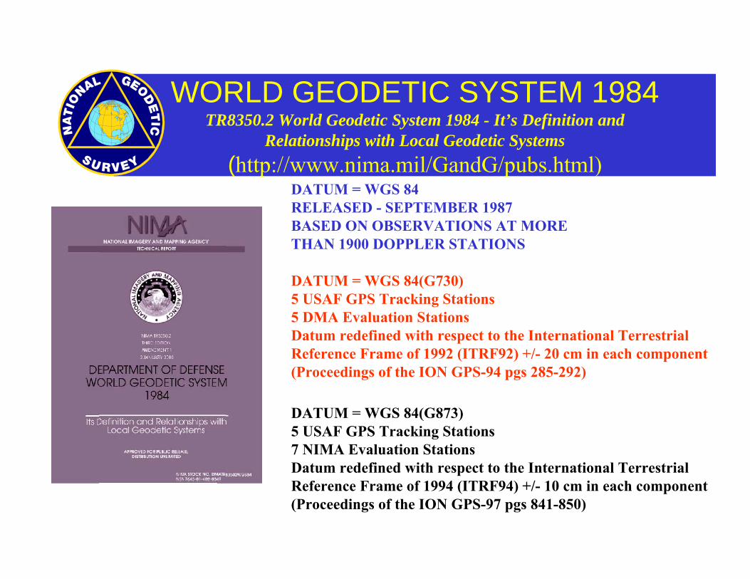
WORLD GEODETIC SYSTEM 1984TR8350.2 World Geodetic System 1984 - It’s Definition and
Relationships with Local Geodetic Systems(http://www.nima.mil/GandG/pubs.html)
DATUM = WGS 84(G730)5 USAF GPS Tracking Stations5 DMA Evaluation Stations Datum redefined with respect to the International TerrestrialReference Frame of 1992 (ITRF92) +/- 20 cm in each component (Proceedings of the ION GPS-94 pgs 285-292)
DATUM = WGS 84(G873)5 USAF GPS Tracking Stations7 NIMA Evaluation Stations Datum redefined with respect to the International TerrestrialReference Frame of 1994 (ITRF94) +/- 10 cm in each component (Proceedings of the ION GPS-97 pgs 841-850)
DATUM = WGS 84RELEASED - SEPTEMBER 1987BASED ON OBSERVATIONS AT MORE THAN 1900 DOPPLER STATIONS
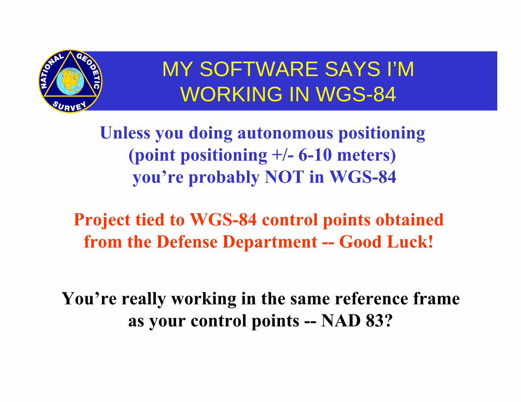
MY SOFTWARE SAYS I’M WORKING IN WGS-84
Project tied to WGS-84 control points obtained from the Defense Department -- Good Luck!
You’re really working in the same reference frame as your control points -- NAD 83?
Unless you doing autonomous positioning (point positioning +/- 6-10 meters) you’re probably NOT in WGS-84
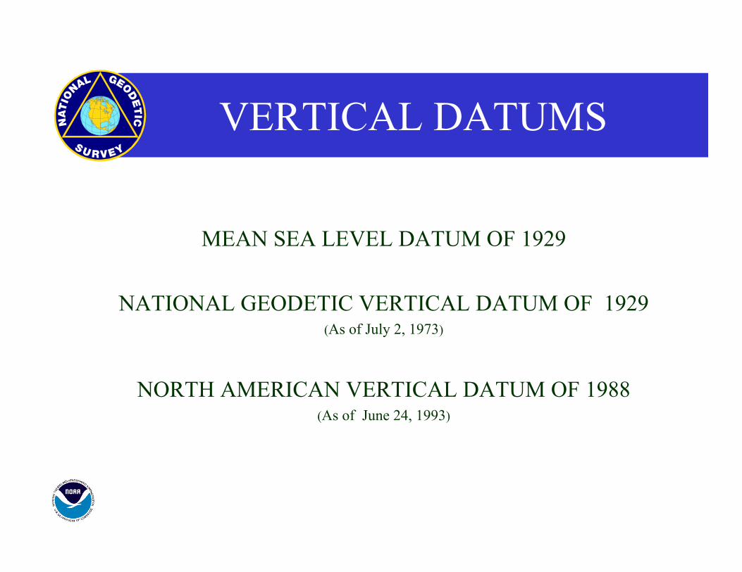
VERTICAL DATUMS
MEAN SEA LEVEL DATUM OF 1929
NATIONAL GEODETIC VERTICAL DATUM OF 1929 (As of July 2, 1973)
NORTH AMERICAN VERTICAL DATUM OF 1988 (As of June 24, 1993)
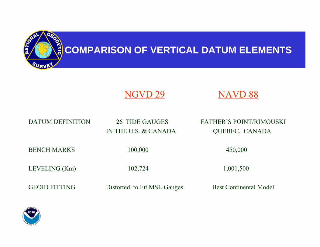
COMPARISON OF VERTICAL DATUM ELEMENTS
NGVD 29 NAVD 88
DATUM DEFINITION 26 TIDE GAUGES FATHER’S POINT/RIMOUSKI IN THE U.S. & CANADA QUEBEC, CANADA
BENCH MARKS 100,000 450,000
LEVELING (Km) 102,724 1,001,500
GEOID FITTING Distorted to Fit MSL Gauges Best Continental Model
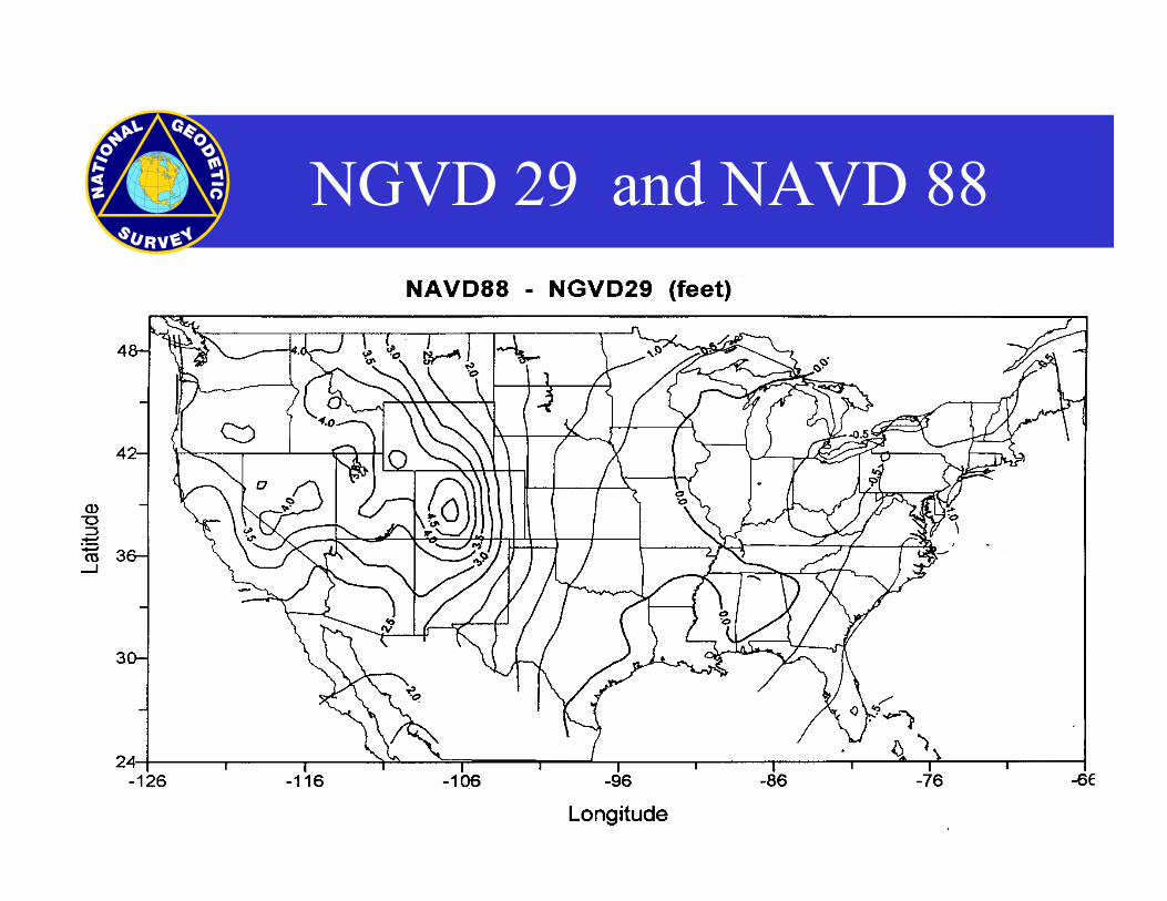
NGVD 29 and NAVD 88
INTERNATIONAL TERRESTRIALREFERENCE SYSTEM
DEVELOPED AND MAINTAINED BY THEINTERNATIONAL EARTH ROTATION SERVICE
PARIS, FRANCE FROM:(http://hpiers.obspm.fr/)
VERY LONG BASELINE INTERFEROMETRY - (VLBI)SATELLITE LASER RANGING - (SLR)
GLOBAL POSITIONING SYSTEM - (GPS)DOPPLER ORBITOGRAPHY AND RADIO POSITIONING
INTEGRATED BY SATELLITE - (DORIS)
INTERNATIONAL TERRESTRIALREFERENCE SYSTEM
GEOCENTRIC +/- 3 to 4 CM
MODELS FOR PLATE TECTONICS
STATION VELOCITIES
POSITIONAL STANDARD ERRORS
REALIZED AS THE INTERNATIONAL TERRESTERIAL REFERENCE FRAME (ITRF)
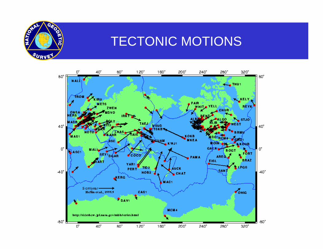
TECTONIC MOTIONS
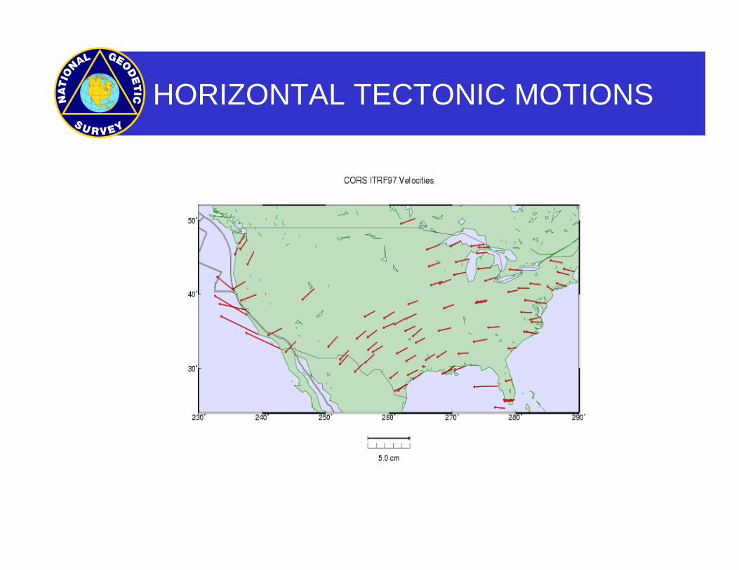
HORIZONTAL TECTONIC MOTIONS
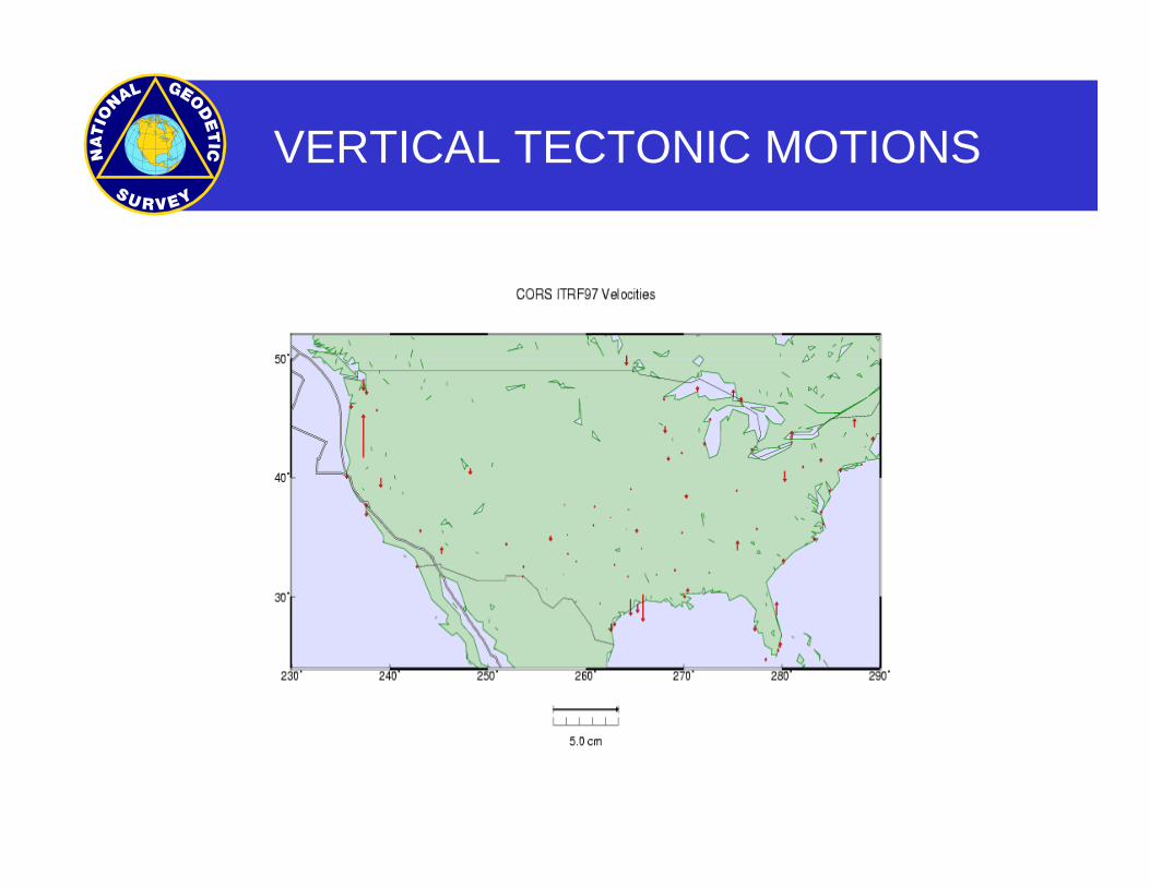
VERTICAL TECTONIC MOTIONS
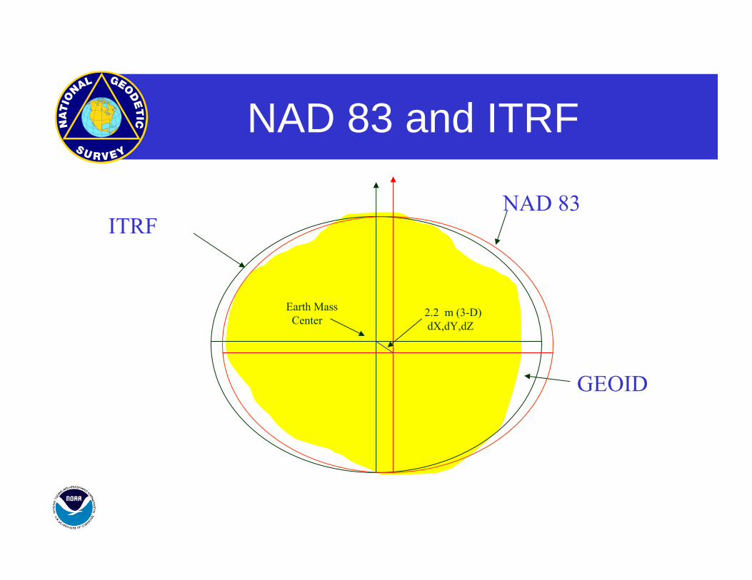
NAD 83 and ITRF
ITRF
NAD 83
Earth MassCenter
2.2 m (3-D)dX,dY,dZ
GEOID
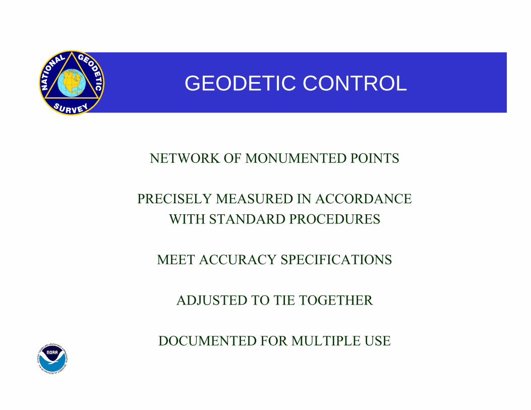
GEODETIC CONTROL
NETWORK OF MONUMENTED POINTS
PRECISELY MEASURED IN ACCORDANCE WITH STANDARD PROCEDURES
MEET ACCURACY SPECIFICATIONS
ADJUSTED TO TIE TOGETHER
DOCUMENTED FOR MULTIPLE USE
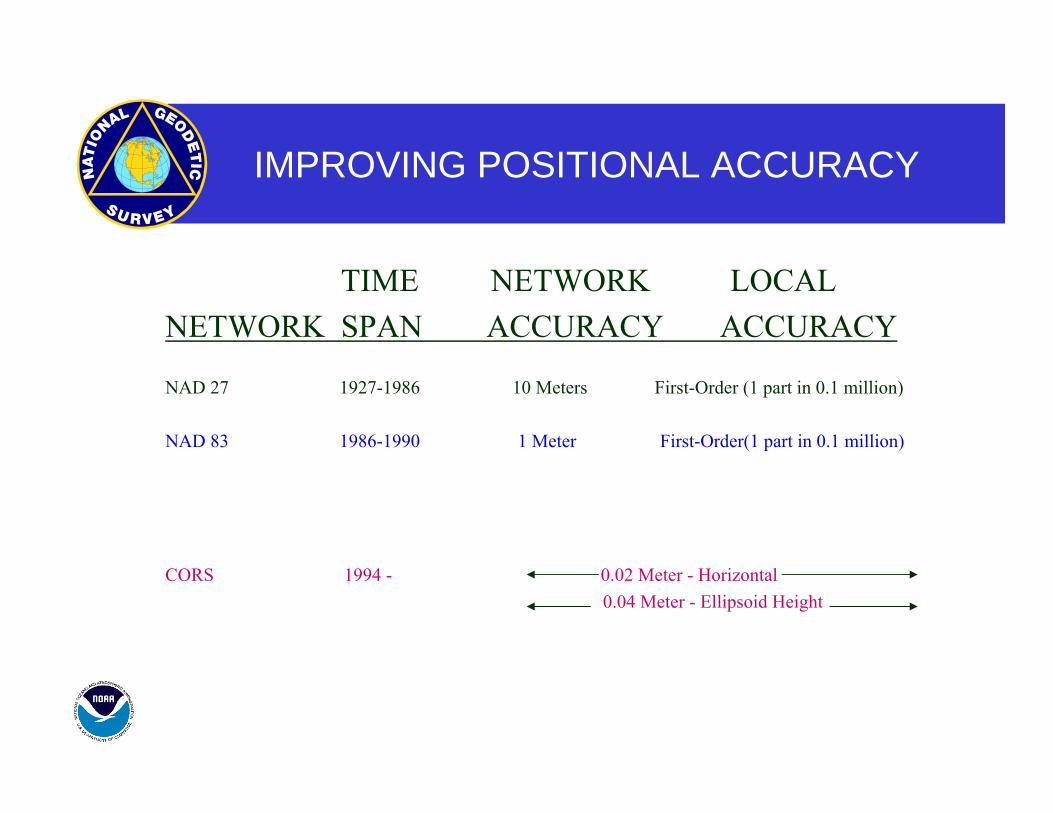
IMPROVING POSITIONAL ACCURACY
TIME NETWORK LOCAL NETWORK SPAN ACCURACY ACCURACY
NAD 27 1927-1986 10 Meters First-Order (1 part in 0.1 million) NAD 83 1986-1990 1 Meter First-Order(1 part in 0.1 million)
HARN 1987-1997 0.1 Meter B-Order(1 part in 1 million) A-Order (1 part in 10 million)
CORS 1994 - 0.02 Meter - Horizontal 0.04 Meter - Ellipsoid Height
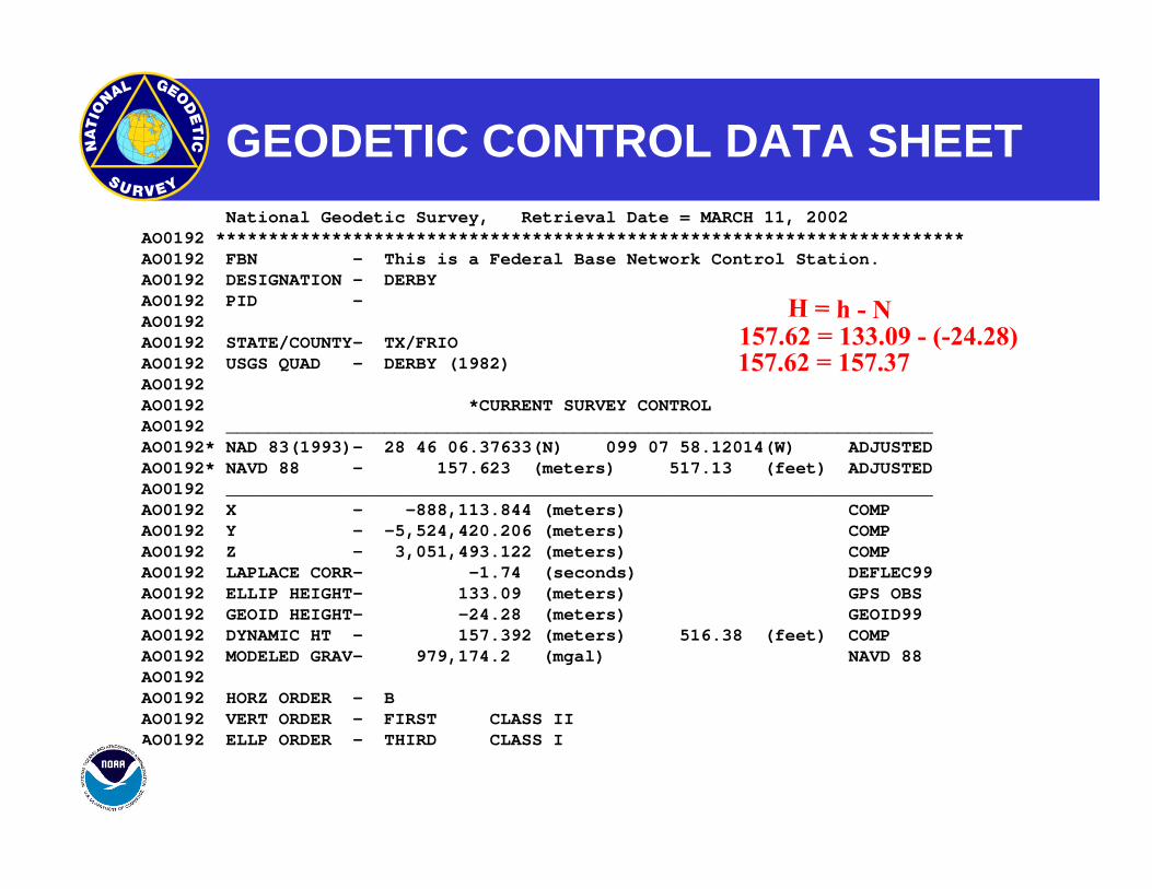
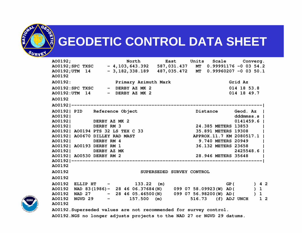
GEODETIC CONTROL DATA SHEET
H = h - N157.62 = 133.09 - (-24.28)157.62 = 157.37
National Geodetic Survey, Retrieval Date = MARCH 11, 2002 AO0192 *********************************************************************** AO0192 FBN - This is a Federal Base Network Control Station. AO0192 DESIGNATION - DERBY AO0192 PID -AO0192 AO0192 STATE/COUNTY- TX/FRIO AO0192 USGS QUAD - DERBY (1982) AO0192 AO0192 *CURRENT SURVEY CONTROL AO0192 ___________________________________________________________________ AO0192* NAD 83(1993)- 28 46 06.37633(N) 099 07 58.12014(W) ADJUSTED AO0192* NAVD 88 - 157.623 (meters) 517.13 (feet) ADJUSTED AO0192 ___________________________________________________________________ AO0192 X - -888,113.844 (meters) COMP AO0192 Y - -5,524,420.206 (meters) COMP AO0192 Z - 3,051,493.122 (meters) COMP AO0192 LAPLACE CORR- -1.74 (seconds) DEFLEC99 AO0192 ELLIP HEIGHT- 133.09 (meters) GPS OBS AO0192 GEOID HEIGHT- -24.28 (meters) GEOID99 AO0192 DYNAMIC HT - 157.392 (meters) 516.38 (feet) COMP AO0192 MODELED GRAV- 979,174.2 (mgal) NAVD 88 AO0192 AO0192 HORZ ORDER - B AO0192 VERT ORDER - FIRST CLASS II AO0192 ELLP ORDER - THIRD CLASS I
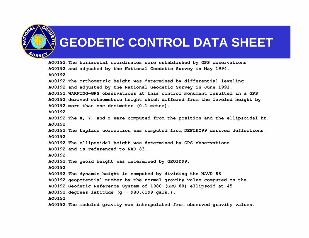
GEODETIC CONTROL DATA SHEET AO0192.The horizontal coordinates were established by GPS observations AO0192.and adjusted by the National Geodetic Survey in May 1994. AO0192 AO0192.The orthometric height was determined by differential leveling AO0192.and adjusted by the National Geodetic Survey in June 1991. AO0192.WARNING-GPS observations at this control monument resulted in a GPS AO0192.derived orthometric height which differed from the leveled height by AO0192.more than one decimeter (0.1 meter). AO0192 AO0192.The X, Y, and Z were computed from the position and the ellipsoidal ht. AO0192 AO0192.The Laplace correction was computed from DEFLEC99 derived deflections. AO0192 AO0192.The ellipsoidal height was determined by GPS observations AO0192.and is referenced to NAD 83. AO0192 AO0192.The geoid height was determined by GEOID99. AO0192 AO0192.The dynamic height is computed by dividing the NAVD 88 AO0192.geopotential number by the normal gravity value computed on the AO0192.Geodetic Reference System of 1980 (GRS 80) ellipsoid at 45 AO0192.degrees latitude (g = 980.6199 gals.). AO0192 AO0192.The modeled gravity was interpolated from observed gravity values.
GEODETIC CONTROL DATA SHEET AO0192; North East Units Scale Converg.
AO0192;SPC TXSC - 4,103,643.392 587,031.437 MT 0.99991176 -0 03 54.2 AO0192;UTM 14 - 3,182,338.189 487,035.472 MT 0.99960207 -0 03 50.1 AO0192
AO0192: Primary Azimuth Mark Grid Az AO0192:SPC TXSC - DERBY AZ MK 2 014 18 53.8
AO0192:UTM 14 - DERBY AZ MK 2 014 18 49.7 AO0192 AO0192|---------------------------------------------------------------------| AO0192| PID Reference Object Distance Geod. Az |
AO0192| dddmmss.s | AO0192| DERBY AZ MK 2 0141459.6 | AO0192| DERBY RM 3 24.385 METERS 13853 | AO0192| AO0194 PTS 32 LS TEX C 33 35.891 METERS 19308 | AO0192| AO0670 DILLEY RAD MAST APPROX.11.7 KM 2080517.1 | AO0192| DERBY RM 4 9.740 METERS 20949 | AO0192| AO0193 DERBY RM 1 36.132 METERS 23658 | AO0192| DERBY AZ MK 2425548.6 | AO0192| AO0530 DERBY RM 2 28.946 METERS 35648 | AO0192|---------------------------------------------------------------------| AO0192
AO0192 SUPERSEDED SURVEY CONTROL AO0192 AO0192 ELLIP HT - 133.22 (m) GP( ) 4 2
AO0192 NAD 83(1986)- 28 46 06.37684(N) 099 07 58.09923(W) AD( ) 1 AO0192 NAD 27 - 28 46 05.46500(N) 099 07 56.98200(W) AD( ) 1 AO0192 NGVD 29 - 157.500 (m) 516.73 (f) ADJ UNCH 1 2 AO0192
AO0192.Superseded values are not recommended for survey control. AO0192.NGS no longer adjusts projects to the NAD 27 or NGVD 29 datums.
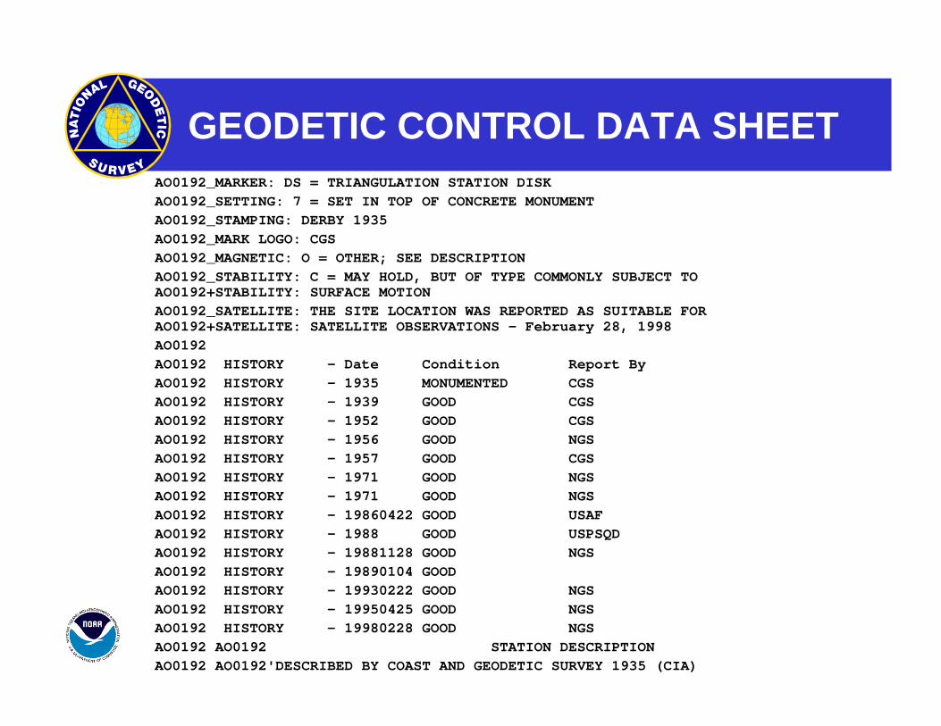
GEODETIC CONTROL DATA SHEET AO0192_MARKER: DS = TRIANGULATION STATION DISK AO0192_SETTING: 7 = SET IN TOP OF CONCRETE MONUMENT AO0192_STAMPING: DERBY 1935 AO0192_MARK LOGO: CGS AO0192_MAGNETIC: O = OTHER; SEE DESCRIPTION AO0192_STABILITY: C = MAY HOLD, BUT OF TYPE COMMONLY SUBJECT TO
AO0192+STABILITY: SURFACE MOTION AO0192_SATELLITE: THE SITE LOCATION WAS REPORTED AS SUITABLE FOR
AO0192+SATELLITE: SATELLITE OBSERVATIONS - February 28, 1998 AO0192 AO0192 HISTORY - Date Condition Report By AO0192 HISTORY - 1935 MONUMENTED CGS AO0192 HISTORY - 1939 GOOD CGS AO0192 HISTORY - 1952 GOOD CGS AO0192 HISTORY - 1956 GOOD NGS AO0192 HISTORY - 1957 GOOD CGS AO0192 HISTORY - 1971 GOOD NGS AO0192 HISTORY - 1971 GOOD NGS AO0192 HISTORY - 19860422 GOOD USAF AO0192 HISTORY - 1988 GOOD USPSQD AO0192 HISTORY - 19881128 GOOD NGS AO0192 HISTORY - 19890104 GOOD AO0192 HISTORY - 19930222 GOOD NGS AO0192 HISTORY - 19950425 GOOD NGS AO0192 HISTORY - 19980228 GOOD NGS AO0192 AO0192 STATION DESCRIPTION AO0192 AO0192'DESCRIBED BY COAST AND GEODETIC SURVEY 1935 (CIA)
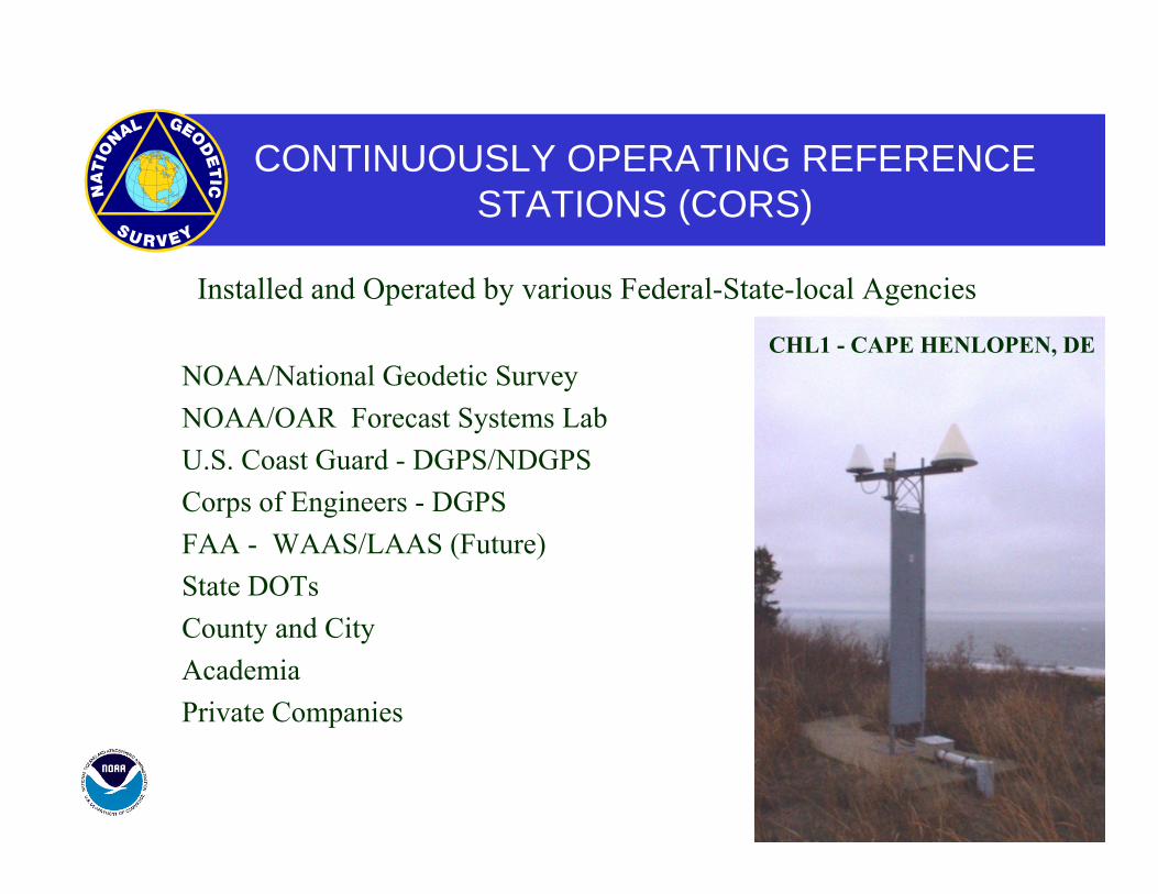
CONTINUOUSLY OPERATING REFERENCE STATIONS (CORS)
Installed and Operated by various Federal-State-local Agencies
NOAA/National Geodetic Survey NOAA/OAR Forecast Systems Lab U.S. Coast Guard - DGPS/NDGPS Corps of Engineers - DGPS FAA - WAAS/LAAS (Future) State DOTs County and City Academia Private Companies
CHL1 - CAPE HENLOPEN, DE
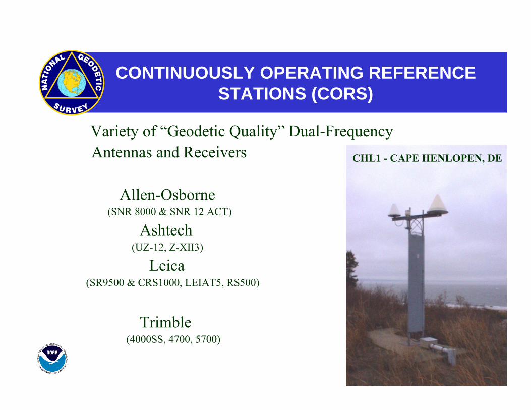
CONTINUOUSLY OPERATING REFERENCE STATIONS (CORS)
Variety of “Geodetic Quality” Dual-Frequency Antennas and Receivers
Allen-Osborne (SNR 8000 & SNR 12 ACT)
Ashtech (UZ-12, Z-XII3)
Leica (SR9500 & CRS1000, LEIAT5, RS500)
Trimble (4000SS, 4700, 5700)
CHL1 - CAPE HENLOPEN, DE
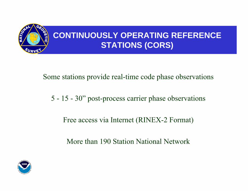
CONTINUOUSLY OPERATING REFERENCE STATIONS (CORS)
Some stations provide real-time code phase observations
5 - 15 - 30” post-process carrier phase observations
Free access via Internet (RINEX-2 Format)
More than 190 Station National Network
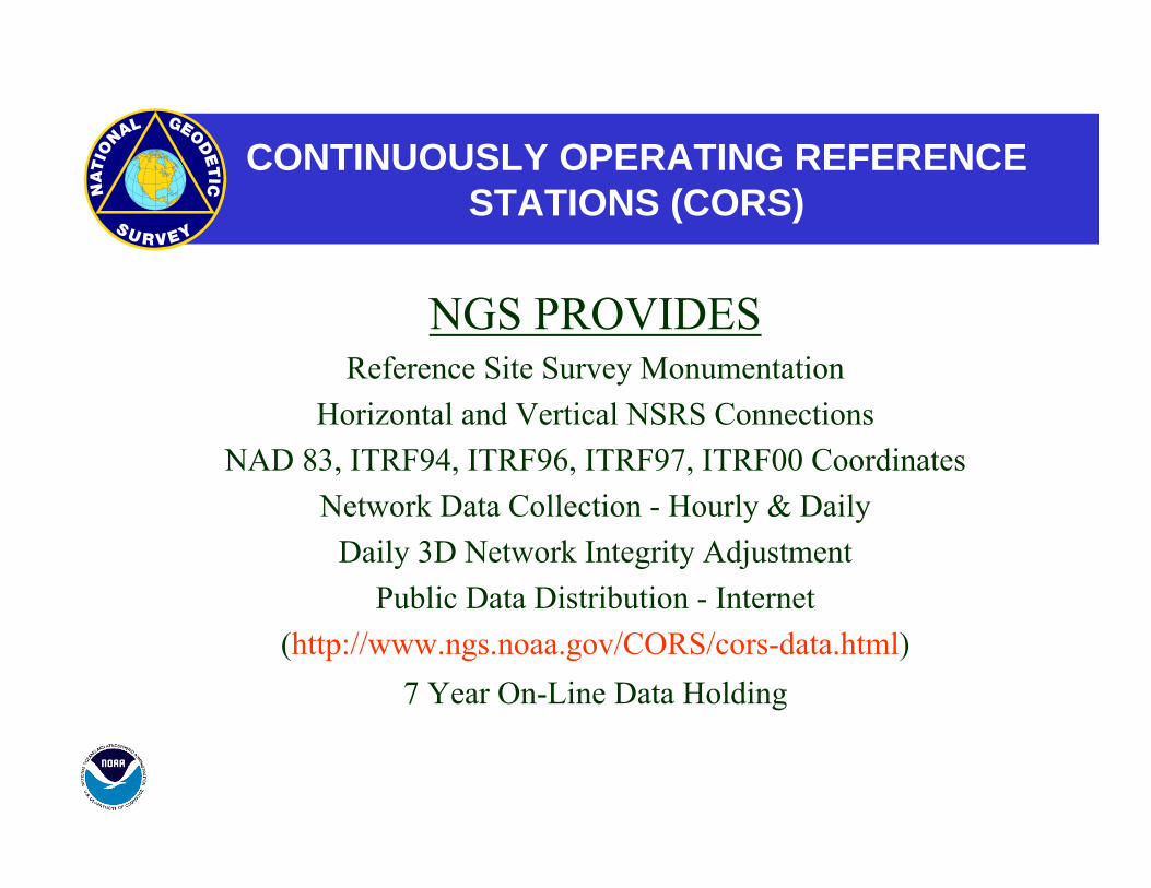
CONTINUOUSLY OPERATING REFERENCE STATIONS (CORS)
NGS PROVIDES Reference Site Survey Monumentation
Horizontal and Vertical NSRS Connections NAD 83, ITRF94, ITRF96, ITRF97, ITRF00 Coordinates
Network Data Collection - Hourly & Daily Daily 3D Network Integrity Adjustment
Public Data Distribution - Internet (http://www.ngs.noaa.gov/CORS/cors-data.html)
7 Year On-Line Data Holding
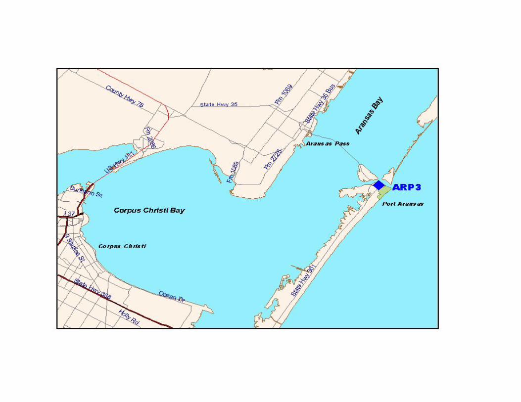
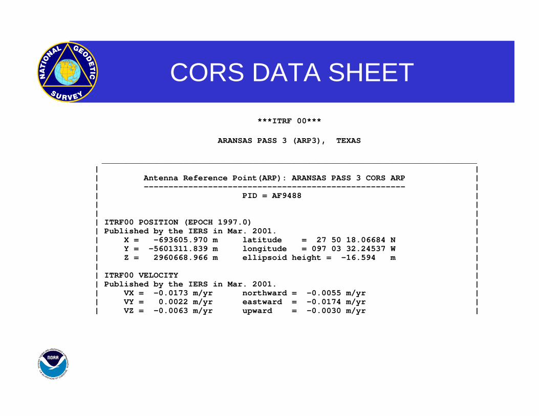
CORS DATA SHEET ***ITRF 00***
ARANSAS PASS 3 (ARP3), TEXAS
____________________________________________________________________________ | || Antenna Reference Point(ARP): ARANSAS PASS 3 CORS ARP || ----------------------------------------------------- || PID = AF9488 || || || ITRF00 POSITION (EPOCH 1997.0) || Published by the IERS in Mar. 2001. || X = -693605.970 m latitude = 27 50 18.06684 N || Y = -5601311.839 m longitude = 097 03 32.24537 W || Z = 2960668.966 m ellipsoid height = -16.594 m || || ITRF00 VELOCITY || Published by the IERS in Mar. 2001. || VX = -0.0173 m/yr northward = -0.0055 m/yr || VY = 0.0022 m/yr eastward = -0.0174 m/yr || VZ = -0.0063 m/yr upward = -0.0030 m/yr |
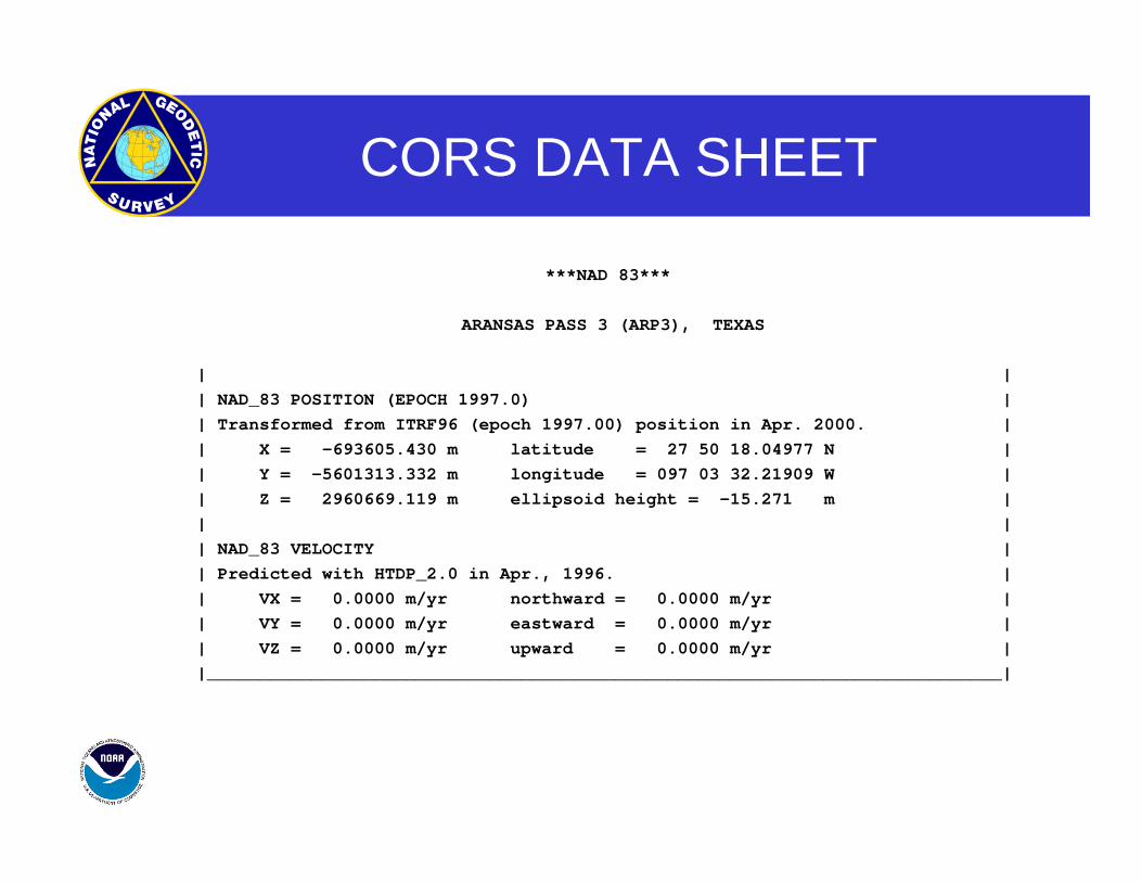
CORS DATA SHEET
***NAD 83***
ARANSAS PASS 3 (ARP3), TEXAS
| | | NAD_83 POSITION (EPOCH 1997.0) | | Transformed from ITRF96 (epoch 1997.00) position in Apr. 2000. | | X = -693605.430 m latitude = 27 50 18.04977 N | | Y = -5601313.332 m longitude = 097 03 32.21909 W | | Z = 2960669.119 m ellipsoid height = -15.271 m | | | | NAD_83 VELOCITY | | Predicted with HTDP_2.0 in Apr., 1996. | | VX = 0.0000 m/yr northward = 0.0000 m/yr | | VY = 0.0000 m/yr eastward = 0.0000 m/yr | | VZ = 0.0000 m/yr upward = 0.0000 m/yr | |____________________________________________________________________________|
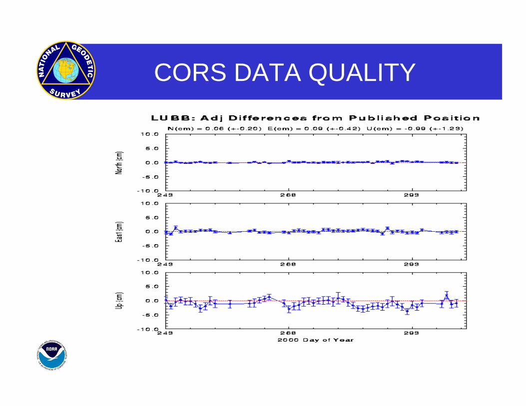
CORS DATA QUALITY
OPUS – WHAT IS IT?
•On-line Positioning User Service
•Provide GPS users faster & easier access to the National Spatial Reference System
(NSRS)

OPUS – HOW DOES IT WORK?
•Submit RINEX file through NGS web page•Processed automatically with NGS computers &
software•With respect to 3 suitable National CORS
•Solution via email in minutes
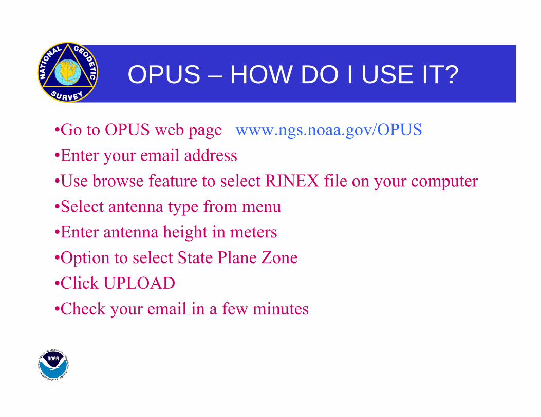
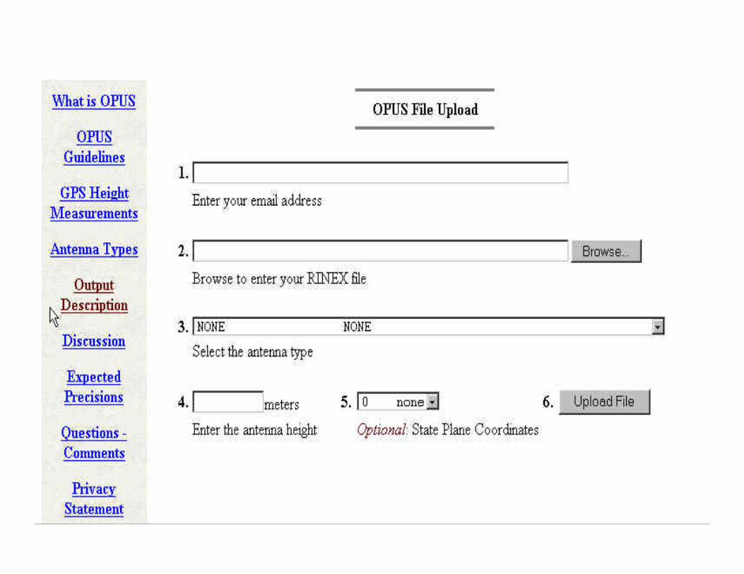
OPUS – HOW DO I USE IT?
•Go to OPUS web page www.ngs.noaa.gov/OPUS•Enter your email address•Use browse feature to select RINEX file on your computer•Select antenna type from menu•Enter antenna height in meters•Option to select State Plane Zone•Click UPLOAD •Check your email in a few minutes
Note: Your solutions will be archived and be publicly available. Your e-mail address will not be retained once the solution is e-mailed to you.
PLANE COORDINATE SYSTEMS
STATE PLANE AND UNIVERSIAL TRANSVERSE MERCATOR GRID COORDINATES ARE A DIRECT MATHEMATICAL CONVERSION FROM LATITUDE AND LONGITUDE TO A CARTESIAN NORTHING AND EASTING (Y & X) COORDINATE SYSTEM,
AND MUST MAINTAIN THE SAME DATUM TAG [e.g. NAD 83(1993)] AS THE LATITUDE AND
LONGITUDE
NATIONAL OCEAN SERVICE
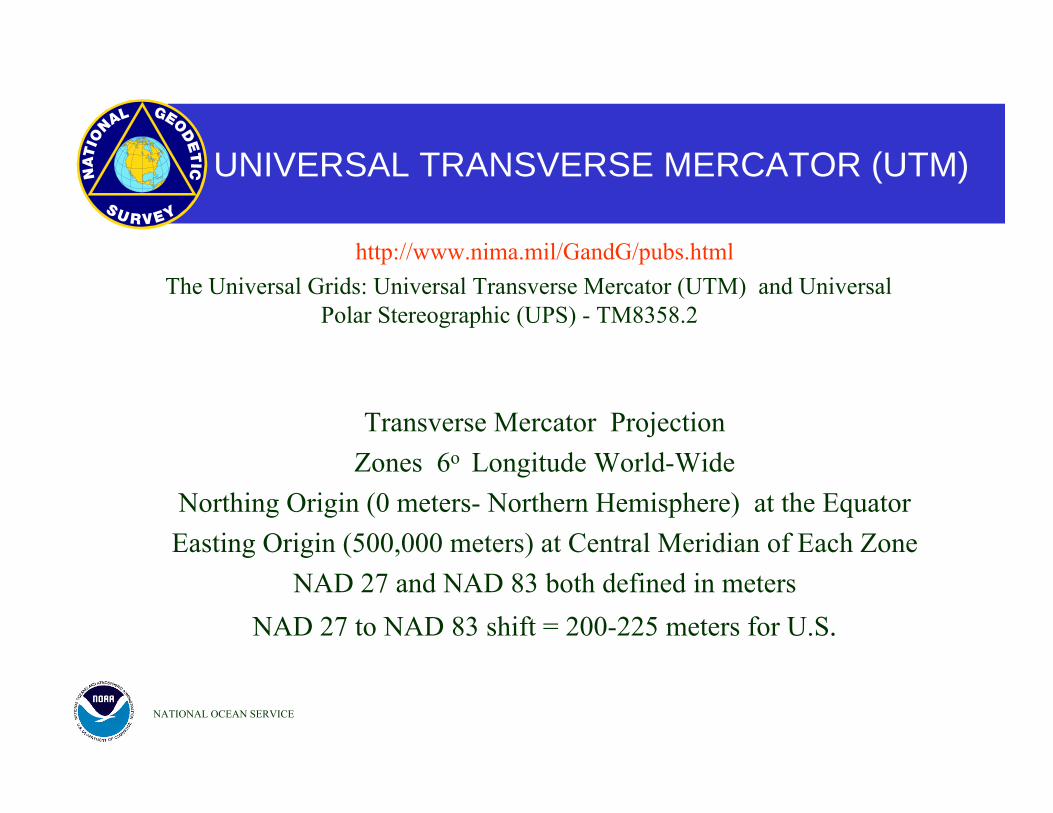
UNIVERSAL TRANSVERSE MERCATOR (UTM)
http://www.nima.mil/GandG/pubs.html The Universal Grids: Universal Transverse Mercator (UTM) and Universal
Polar Stereographic (UPS) - TM8358.2
Transverse Mercator Projection Zones 6o Longitude World-Wide
Northing Origin (0 meters- Northern Hemisphere) at the Equator Easting Origin (500,000 meters) at Central Meridian of Each Zone
NAD 27 and NAD 83 both defined in meters NAD 27 to NAD 83 shift = 200-225 meters for U.S.
NATIONAL OCEAN SERVICE
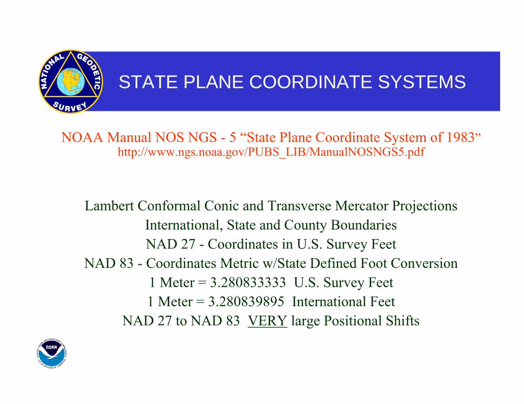
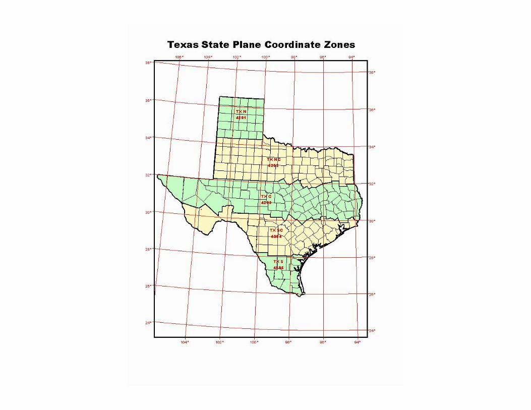
STATE PLANE COORDINATE SYSTEMS
NOAA Manual NOS NGS - 5 “State Plane Coordinate System of 1983”http://www.ngs.noaa.gov/PUBS_LIB/ManualNOSNGS5.pdf
Lambert Conformal Conic and Transverse Mercator Projections International, State and County Boundaries NAD 27 - Coordinates in U.S. Survey Feet
NAD 83 - Coordinates Metric w/State Defined Foot Conversion 1 Meter = 3.280833333 U.S. Survey Feet 1 Meter = 3.280839895 International Feet
NAD 27 to NAD 83 VERY large Positional Shifts
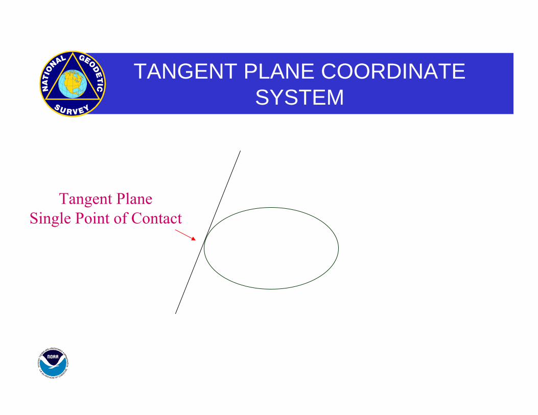
TANGENT PLANE COORDINATE SYSTEM
Tangent PlaneSingle Point of Contact
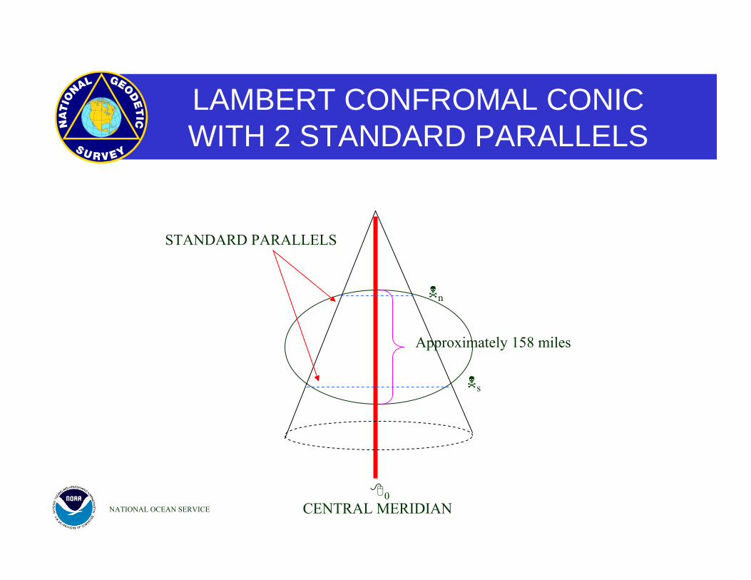
LAMBERT CONFROMAL CONICWITH 2 STANDARD PARALLELS
NATIONAL OCEAN SERVICE
Approximately 158 miles
CENTRAL MERIDIAN
STANDARD PARALLELS
n
s
0
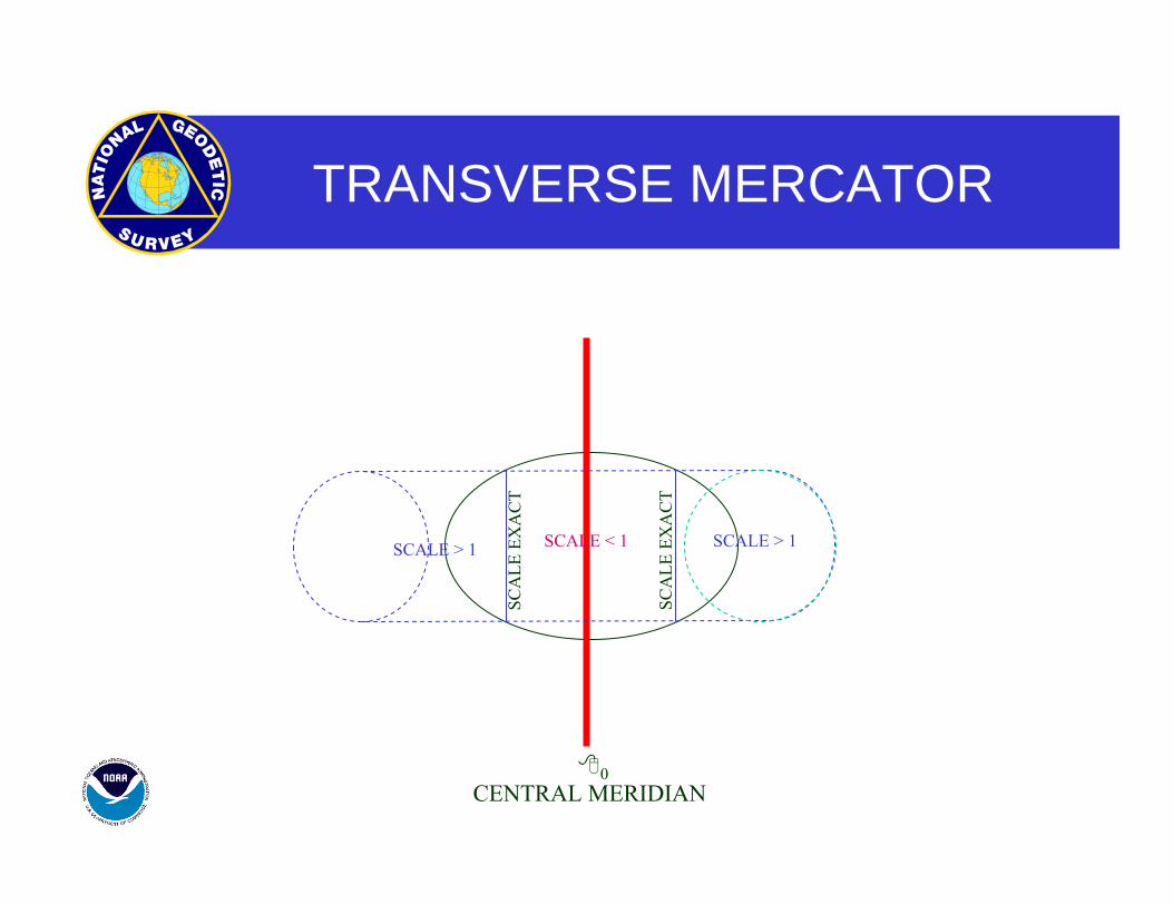
TRANSVERSE MERCATOR
CENTRAL MERIDIAN0
SCA
LE E
XA
CT
SCA
LE E
XA
CT
SCALE < 1 SCALE > 1SCALE > 1
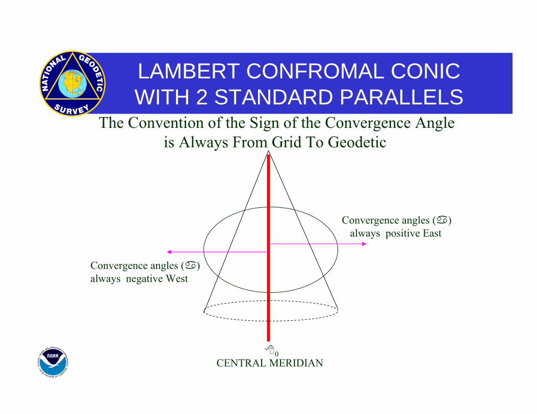
LAMBERT CONFROMAL CONICWITH 2 STANDARD PARALLELS
CENTRAL MERIDIAN0
Convergence angles ( ) always positive East
Convergence angles ( ) always negative West
The Convention of the Sign of the Convergence Angle is Always From Grid To Geodetic
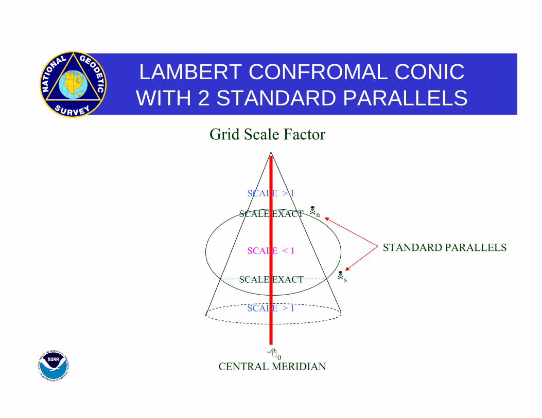
LAMBERT CONFROMAL CONICWITH 2 STANDARD PARALLELS
CENTRAL MERIDIAN
STANDARD PARALLELS
n
s
0
SCALE EXACT
SCALE EXACT
SCALE < 1
SCALE > 1
SCALE > 1
Grid Scale Factor
Apex of Cone
Northern Standard Parallel
Southern Standard Parallel
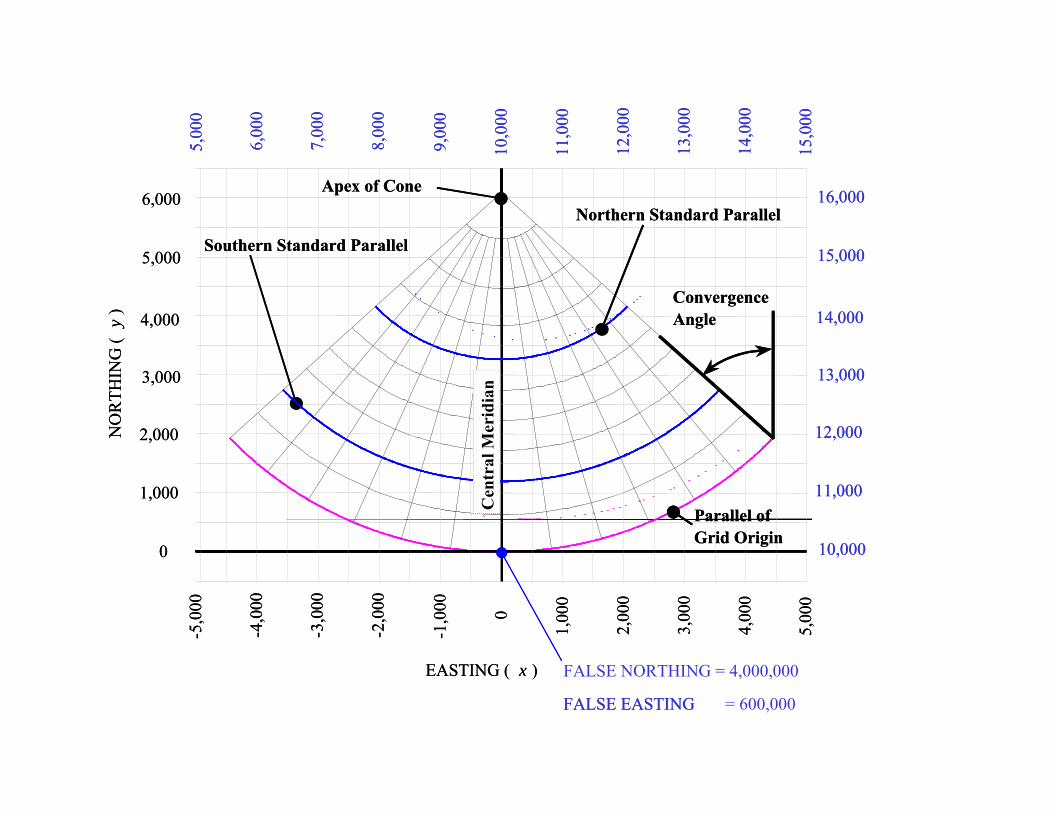
FALSE NORTHING = 4,000,000
FALSE EASTING = 600,000
Parallel ofGrid Origin
ConvergenceAngle
EASTING ( x )
NO
RTH
ING
( y
)
-1,0
00
-2,0
00
-3,0
00
-4,0
00
-5,0
00
5,00
0
4,00
0
3,00
0
2,00
0
1,00
0
0
9,00
0
8,00
0
7,00
0
6,00
0
5,00
0
15,0
00
14,0
00
13,0
00
12,0
00
11,0
00
10,0
00
0
5,000
4,000
3,000
2,000
1,000
6,000
10,000
15,000
14,000
13,000
12,000
11,000
16,000
Cen
tral
Mer
idia
n
Apex of Cone
Northern Standard Parallel
Southern Standard Parallel
FALSE EASTING
Parallel ofGrid Origin
ConvergenceAngle
EASTING ( x )
NO
RTH
ING
( y
)
-1,0
00
-2,0
00
-3,0
00
-4,0
00
-5,0
00
5,00
0
4,00
0
3,00
0
2,00
0
1,00
0
0
9,00
0
8,00
0
7,00
0
6,00
0
5,00
0
15,0
00
14,0
00
13,0
00
12,0
00
11,0
00
10,0
00
0
5,000
4,000
3,000
2,000
1,000
6,000
10,000
15,000
14,000
13,000
12,000
11,000
16,000
Cen
tral
Mer
idia
n
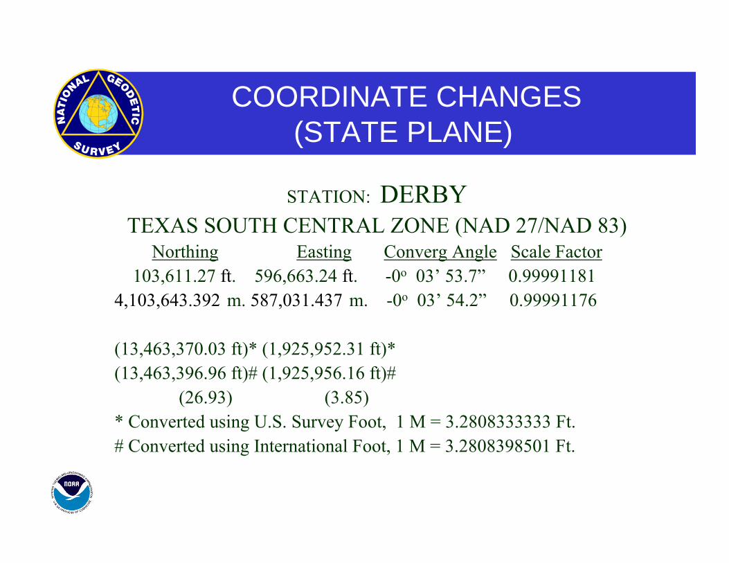
COORDINATE CHANGES(STATE PLANE)
STATION: DERBY TEXAS SOUTH CENTRAL ZONE (NAD 27/NAD 83)
Northing Easting Converg Angle Scale Factor 103,611.27 ft. 596,663.24 ft. -0o 03’ 53.7” 0.99991181 4,103,643.392 m. 587,031.437 m. -0o 03’ 54.2” 0.99991176
(13,463,370.03 ft)* (1,925,952.31 ft)* (13,463,396.96 ft)# (1,925,956.16 ft)# (26.93) (3.85) * Converted using U.S. Survey Foot, 1 M = 3.2808333333 Ft. # Converted using International Foot, 1 M = 3.2808398501 Ft.
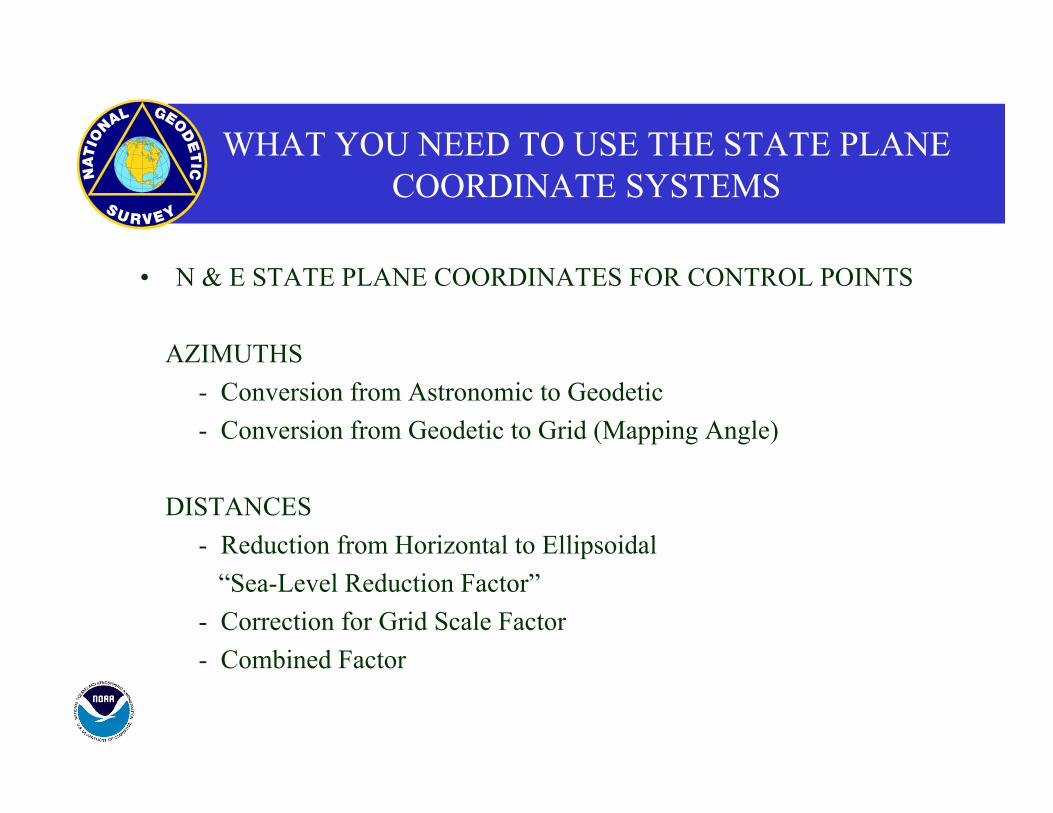
WHAT YOU NEED TO USE THE STATE PLANE COORDINATE SYSTEMS
• N & E STATE PLANE COORDINATES FOR CONTROL POINTS
AZIMUTHS - Conversion from Astronomic to Geodetic - Conversion from Geodetic to Grid (Mapping Angle)
DISTANCES - Reduction from Horizontal to Ellipsoidal “Sea-Level Reduction Factor” - Correction for Grid Scale Factor - Combined Factor
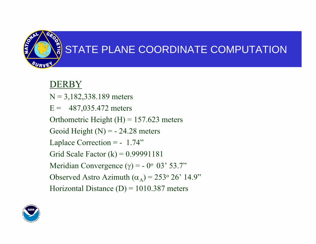
STATE PLANE COORDINATE COMPUTATION
DERBY N = 3,182,338.189 meters E = 487,035.472 meters Orthometric Height (H) = 157.623 meters Geoid Height (N) = - 24.28 meters Laplace Correction = - 1.74” Grid Scale Factor (k) = 0.99991181 Meridian Convergence (γ) = - 0o 03’ 53.7” Observed Astro Azimuth (αA) = 253o 26’ 14.9” Horizontal Distance (D) = 1010.387 meters
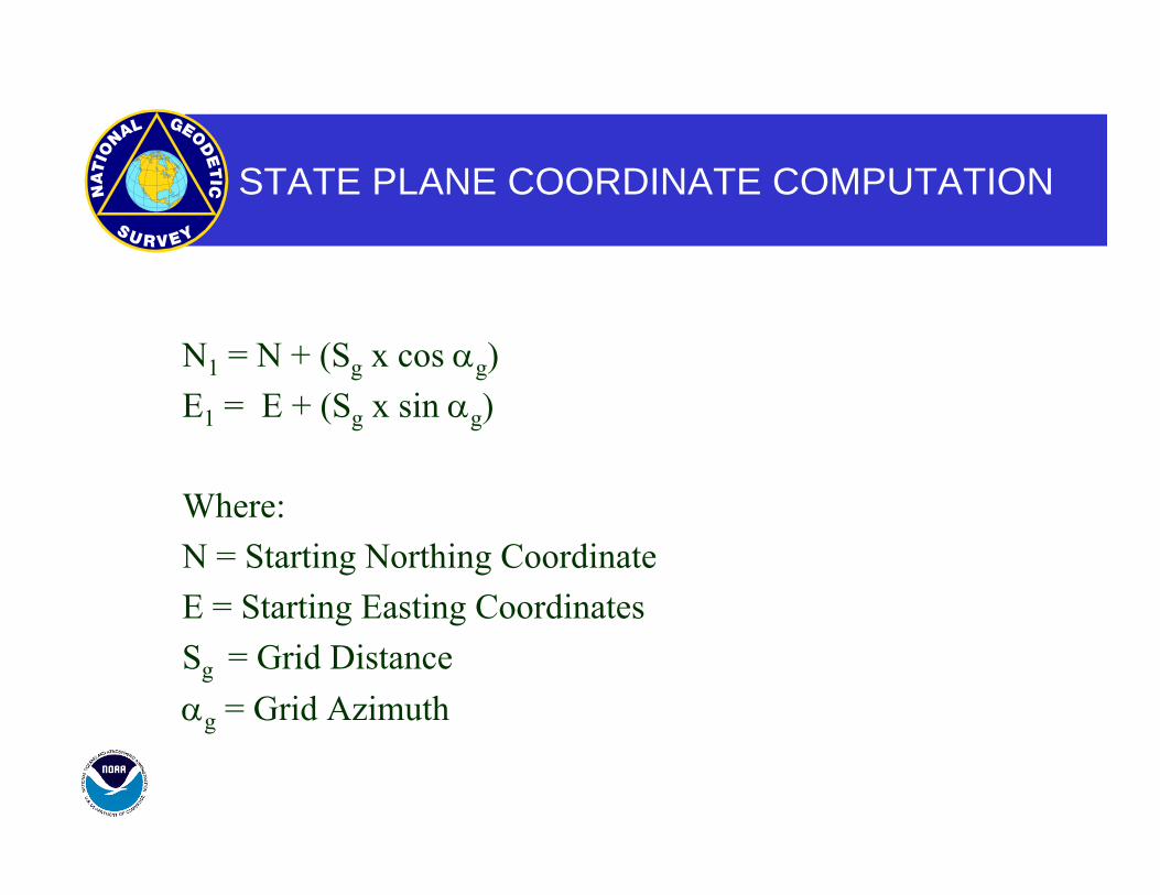
STATE PLANE COORDINATE COMPUTATION
N1 = N + (Sg x cos αg) E1 = E + (Sg x sin αg)
Where: N = Starting Northing Coordinate E = Starting Easting Coordinates Sg = Grid Distance αg = Grid Azimuth
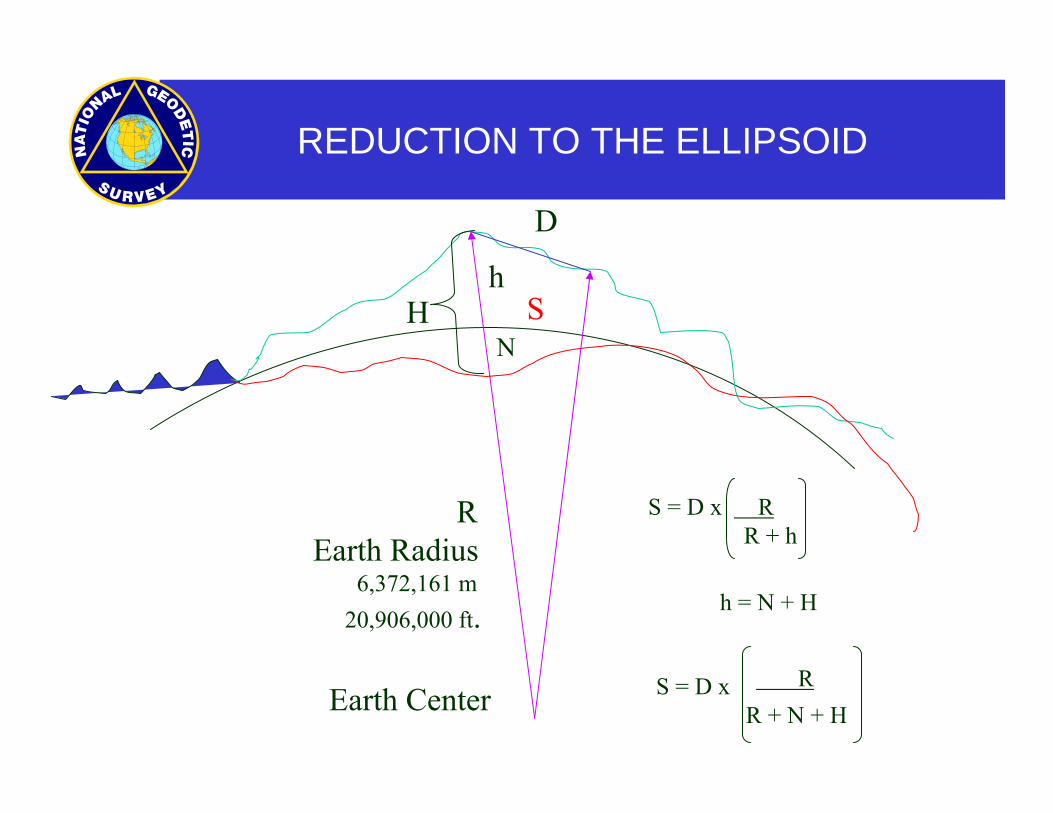
REDUCTION TO THE ELLIPSOID
h
NH
REarth Radius
6,372,161 m20,906,000 ft.
Earth Center
S
D
S = D x R R + h
h = N + H
S = D xR + N + H R
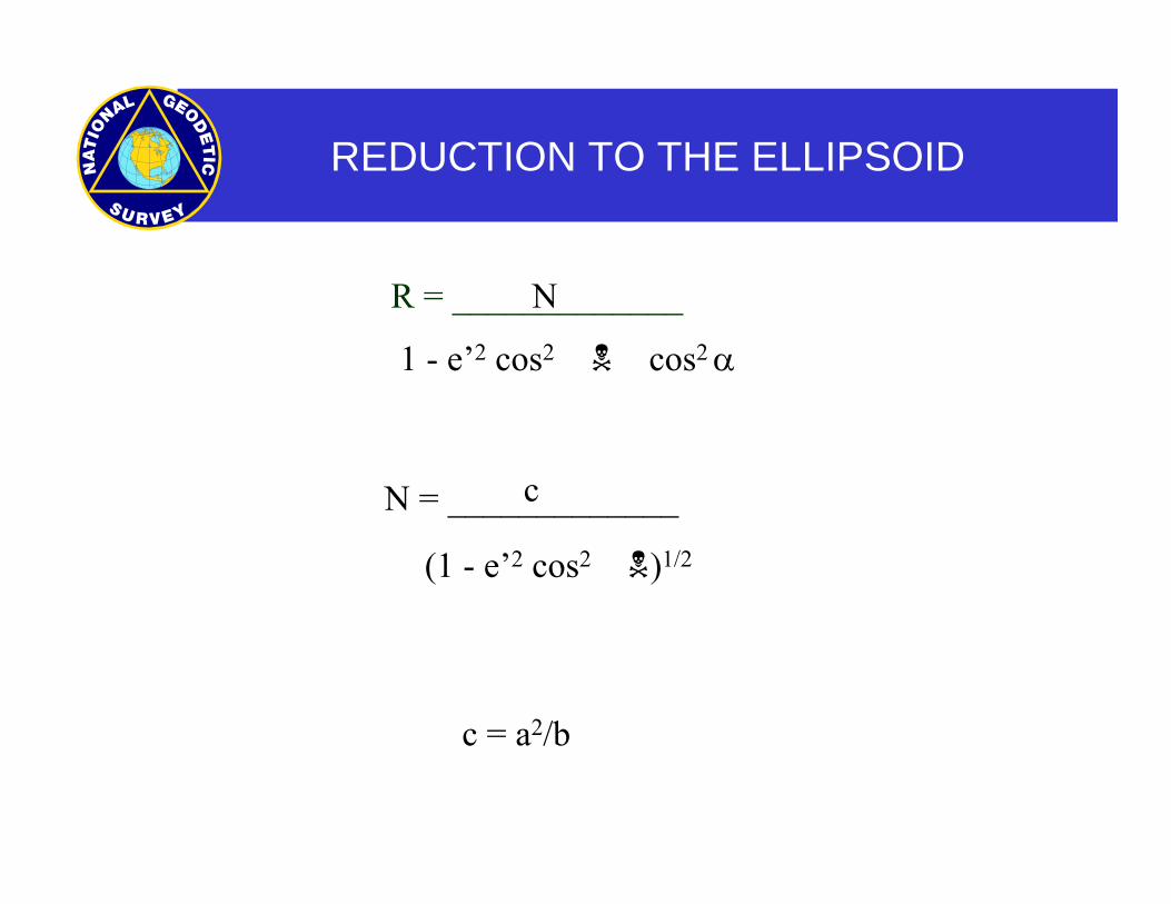
REDUCTION TO THE ELLIPSOID
R = _____________N
1 - e’2 cos2 cos2 α
N = _____________c
(1 - e’2 cos2 )1/2
c = a2/b
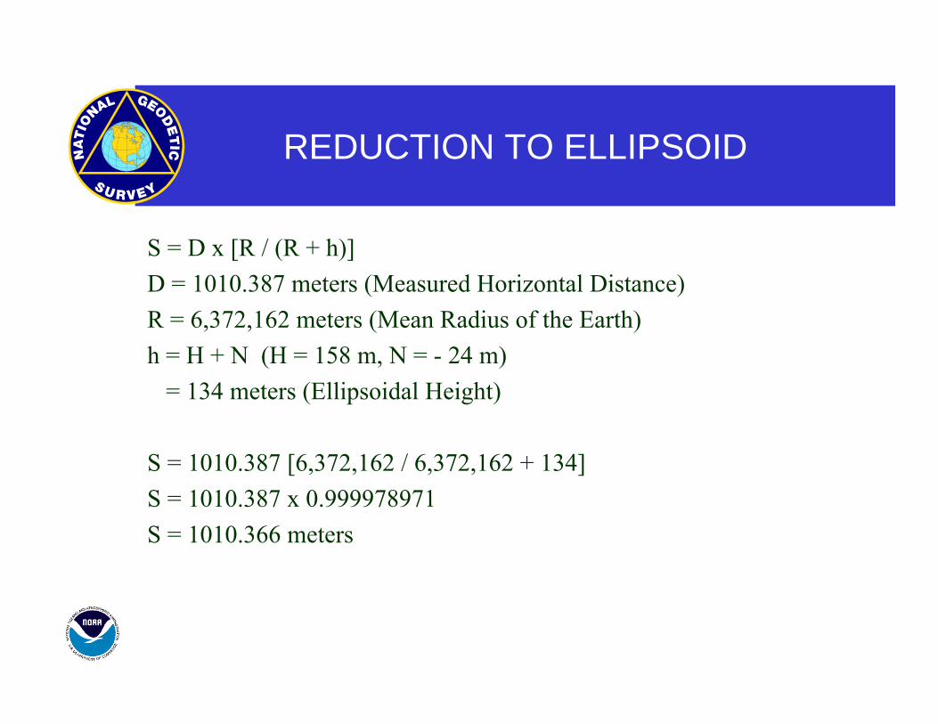
REDUCTION TO ELLIPSOID
S = D x [R / (R + h)] D = 1010.387 meters (Measured Horizontal Distance) R = 6,372,162 meters (Mean Radius of the Earth) h = H + N (H = 158 m, N = - 24 m) = 134 meters (Ellipsoidal Height)
S = 1010.387 [6,372,162 / 6,372,162 + 134] S = 1010.387 x 0.999978971 S = 1010.366 meters
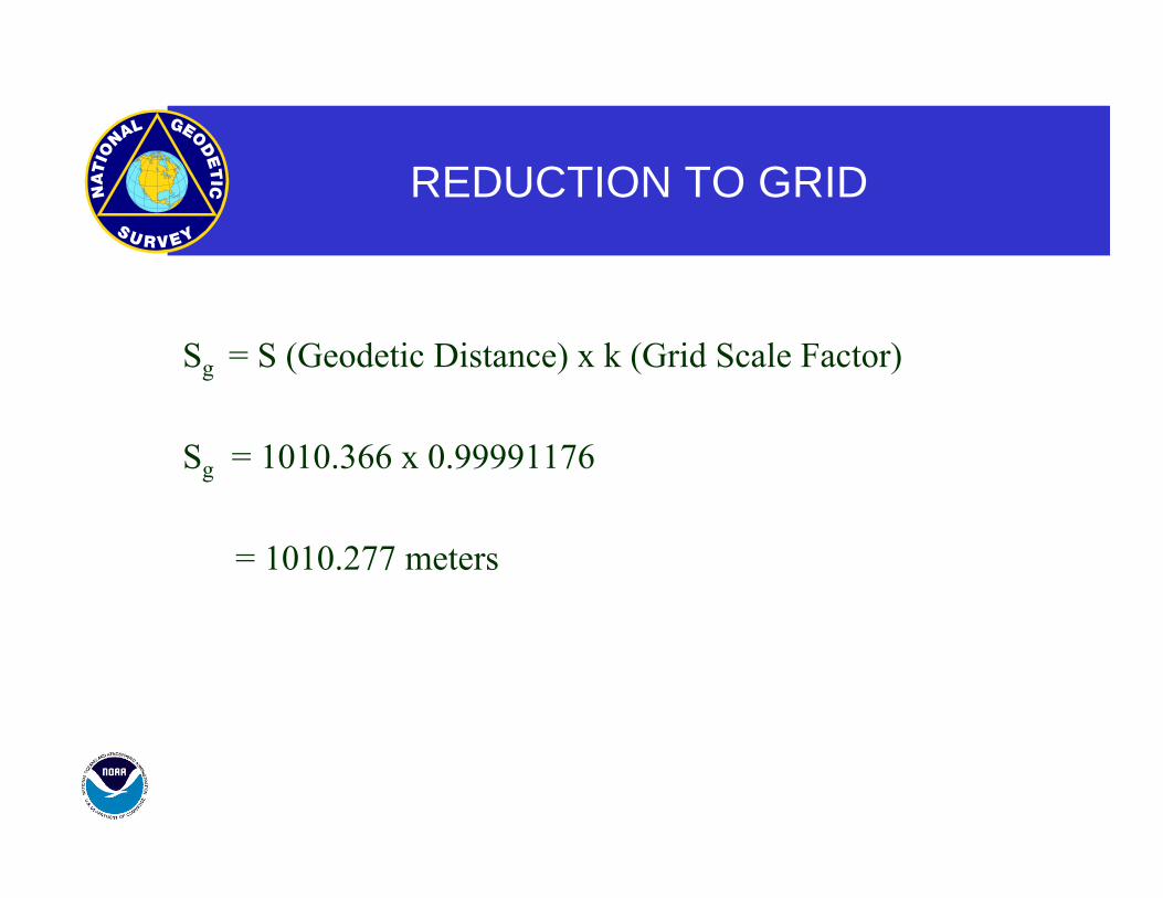
REDUCTION TO GRID
Sg = S (Geodetic Distance) x k (Grid Scale Factor)
Sg = 1010.366 x 0.99991176
= 1010.277 meters
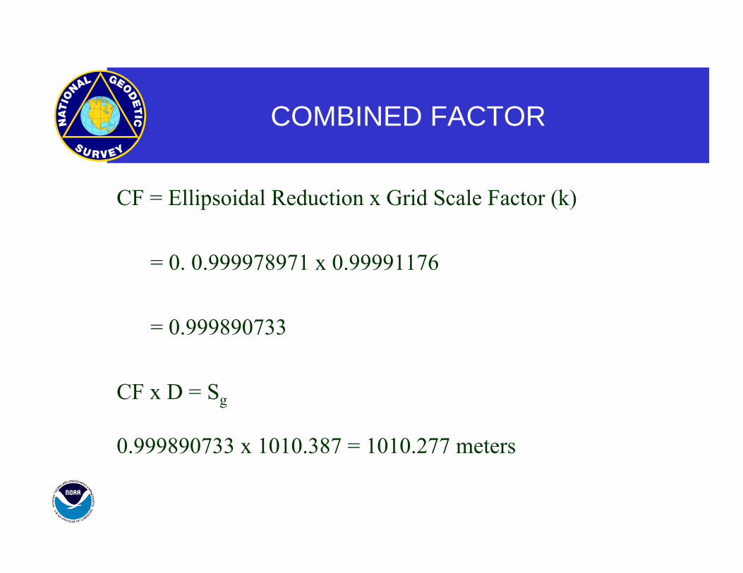
COMBINED FACTOR
CF = Ellipsoidal Reduction x Grid Scale Factor (k)
= 0. 0.999978971 x 0.99991176
= 0.999890733
CF x D = Sg
0.999890733 x 1010.387 = 1010.277 meters
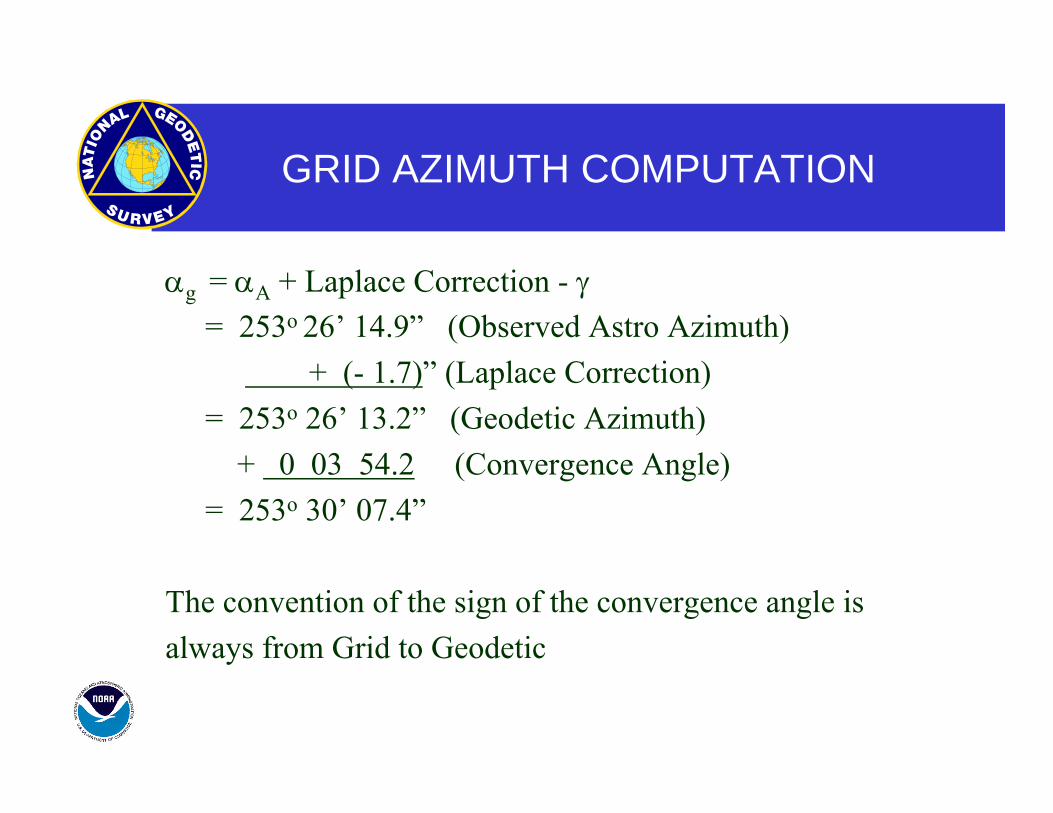
GRID AZIMUTH COMPUTATION
αg = αA + Laplace Correction - γ = 253o 26’ 14.9” (Observed Astro Azimuth) + (- 1.7)” (Laplace Correction) = 253o 26’ 13.2” (Geodetic Azimuth) + 0 03 54.2 (Convergence Angle) = 253o 30’ 07.4”
The convention of the sign of the convergence angle is always from Grid to Geodetic
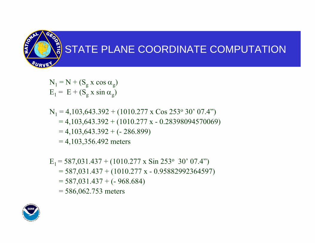
STATE PLANE COORDINATE COMPUTATION
N1 = N + (Sg x cos αg) E1 = E + (Sg x sin αg)
N1 = 4,103,643.392 + (1010.277 x Cos 253o 30’ 07.4”) = 4,103,643.392 + (1010.277 x - 0.28398094570069) = 4,103,643.392 + (- 286.899) = 4,103,356.492 meters
E1 = 587,031.437 + (1010.277 x Sin 253o 30’ 07.4”) = 587,031.437 + (1010.277 x - 0.95882992364597) = 587,031.437 + (- 968.684) = 586,062.753 meters
GROUND LEVEL COORDINATES
“I WANT STATE PLANE COORDINATES RAISED TO GROUND LEVEL”
GROUND LEVEL COORDINATES ARE NOTSTATE PLANE COORDINATES!!!!!
GROUND LEVEL COORDINATESPROBLEMS
RAPID DISTORTIONS
PROJECTS DIFFICULT TO TIE TOGETHER
CONFUSION OF COORDINATE SYSTEMS
LACK OF DOCUMENTATION
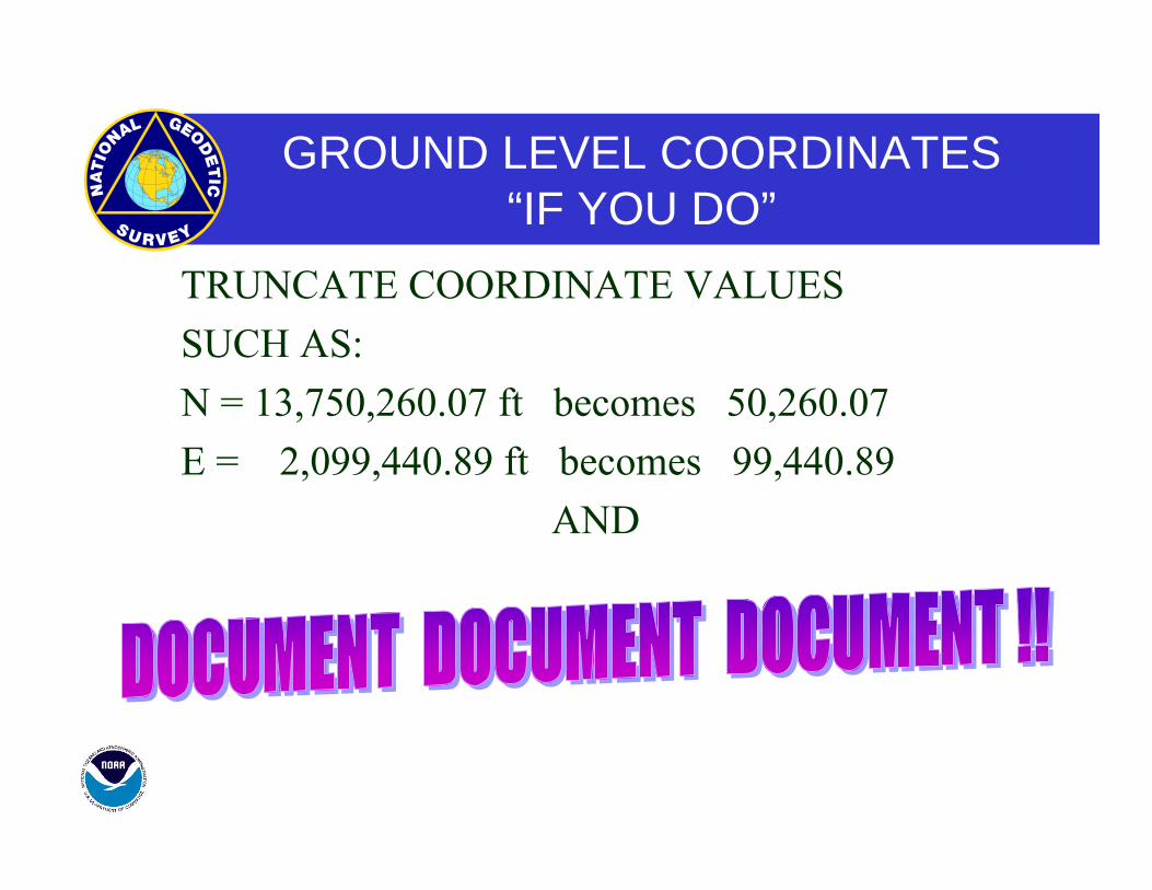
GROUND LEVEL COORDINATES“IF YOU DO”
TRUNCATE COORDINATE VALUES SUCH AS: N = 13,750,260.07 ft becomes 50,260.07 E = 2,099,440.89 ft becomes 99,440.89
AND
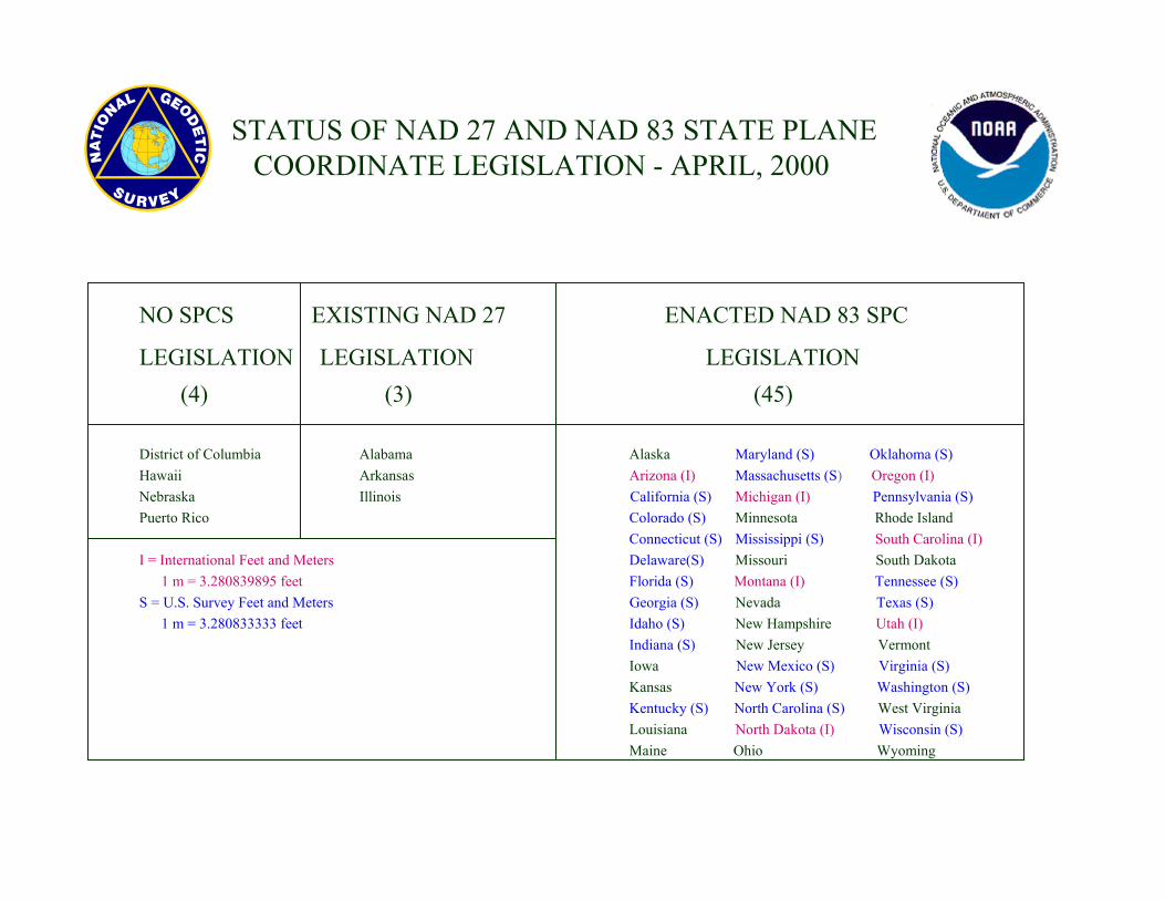
NO SPCS EXISTING NAD 27 ENACTED NAD 83 SPC
LEGISLATION LEGISLATION LEGISLATION (4) (3) (45)
District of Columbia Alabama Alaska Maryland (S) Oklahoma (S) Hawaii Arkansas Arizona (I) Massachusetts (S) Oregon (I) Nebraska Illinois California (S) Michigan (I) Pennsylvania (S) Puerto Rico Colorado (S) Minnesota Rhode Island Connecticut (S) Mississippi (S) South Carolina (I) I = International Feet and Meters Delaware(S) Missouri South Dakota 1 m = 3.280839895 feet Florida (S) Montana (I) Tennessee (S) S = U.S. Survey Feet and Meters Georgia (S) Nevada Texas (S) 1 m = 3.280833333 feet Idaho (S) New Hampshire Utah (I)
Indiana (S) New Jersey Vermont Iowa New Mexico (S) Virginia (S) Kansas New York (S) Washington (S) Kentucky (S) North Carolina (S) West Virginia Louisiana North Dakota (I) Wisconsin (S) Maine Ohio Wyoming
STATUS OF NAD 27 AND NAD 83 STATE PLANECOORDINATE LEGISLATION - APRIL, 2000
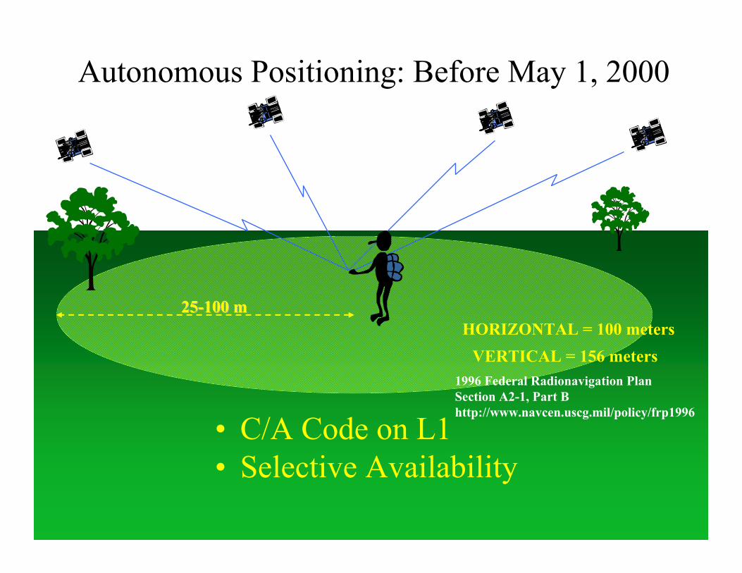
Autonomous Positioning: Before May 1, 2000
• C/A Code on L1• Selective Availability
2525--100 m100 mHORIZONTAL = 100 meters
VERTICAL = 156 meters1996 Federal Radionavigation PlanSection A2-1, Part Bhttp://www.navcen.uscg.mil/policy/frp1996
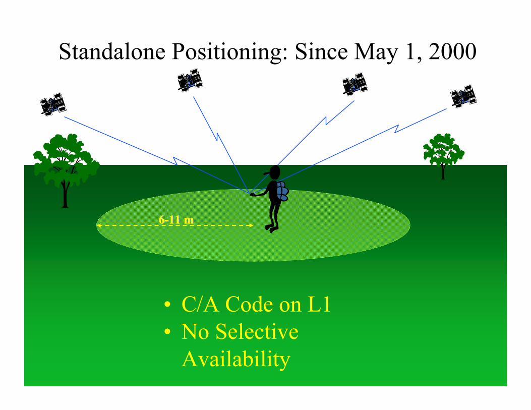
Standalone Positioning: Since May 1, 2000
• C/A Code on L1• No Selective
Availability
66--11 m11 m
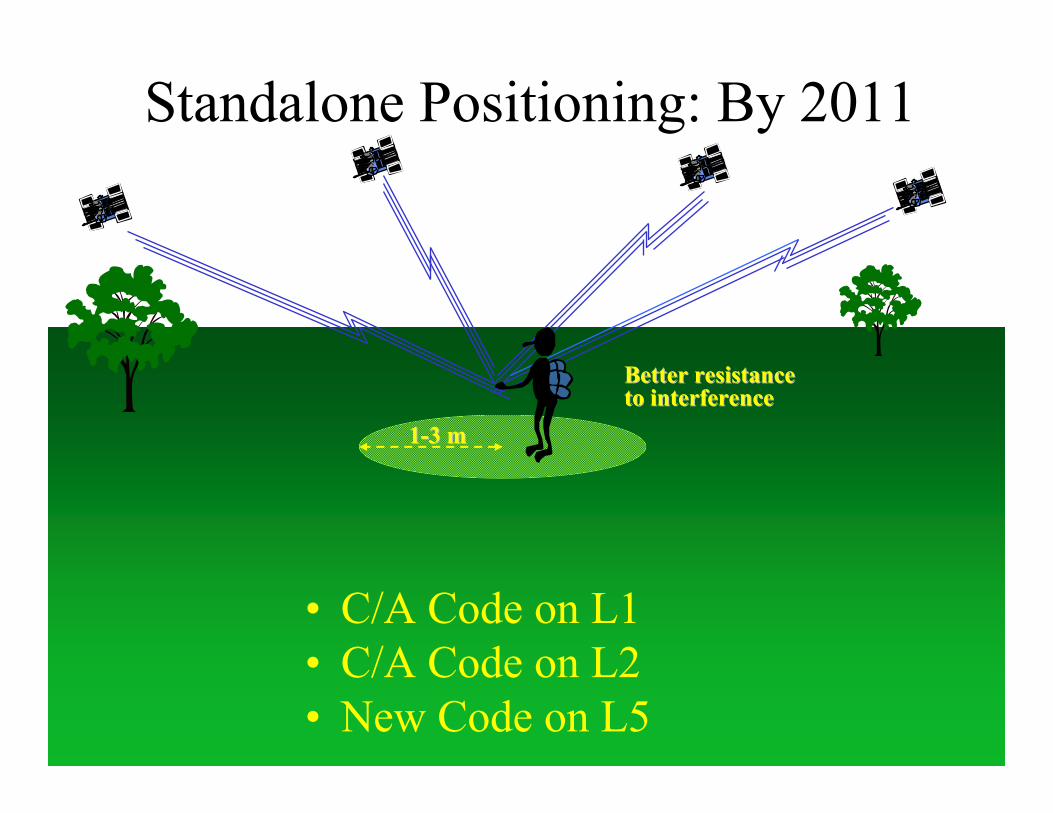
Standalone Positioning: By 2011
• C/A Code on L1• C/A Code on L2• New Code on L5
11--3 m3 m
Better resistance Better resistance to interferenceto interference
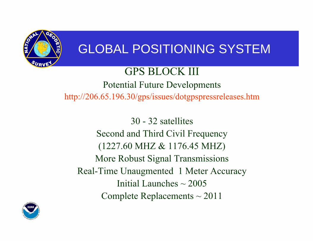
GLOBAL POSITIONING SYSTEM
GPS BLOCK III Potential Future Developments
http://206.65.196.30/gps/issues/dotgpspressreleases.htm
30 - 32 satellites Second and Third Civil Frequency (1227.60 MHZ & 1176.45 MHZ)
More Robust Signal Transmissions Real-Time Unaugmented 1 Meter Accuracy
Initial Launches ~ 2005 Complete Replacements ~ 2011
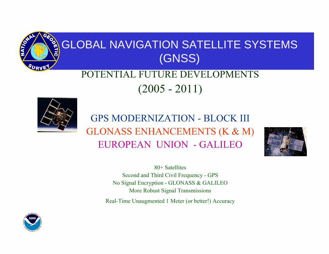
GLOBAL NAVIGATION SATELLITE SYSTEMS(GNSS)
POTENTIAL FUTURE DEVELOPMENTS (2005 - 2011)
GPS MODERNIZATION - BLOCK III GLONASS ENHANCEMENTS (K & M)
EUROPEAN UNION - GALILEO
80+ Satellites Second and Third Civil Frequency - GPS
No Signal Encryption - GLONASS & GALILEO More Robust Signal Transmissions
Real-Time Unaugmented 1 Meter (or better!) Accuracy
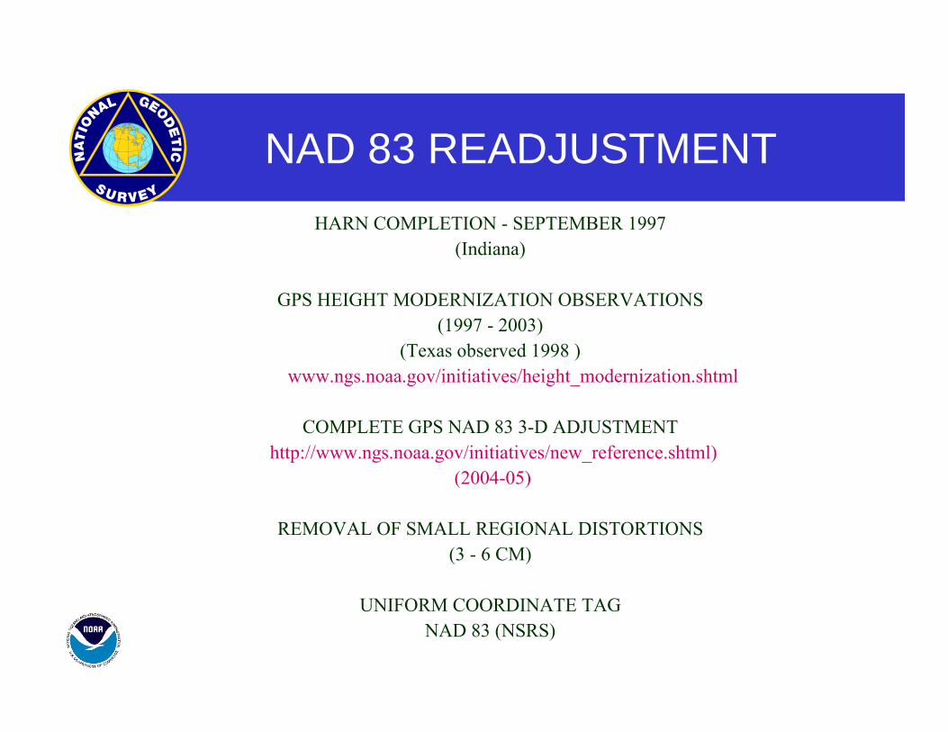
NAD 83 READJUSTMENT HARN COMPLETION - SEPTEMBER 1997
(Indiana)
GPS HEIGHT MODERNIZATION OBSERVATIONS (1997 - 2003)
(Texas observed 1998 ) (http://www.ngs.noaa.gov/initiatives/height_modernization.shtml
COMPLETE GPS NAD 83 3-D ADJUSTMENT (http://www.ngs.noaa.gov/initiatives/new_reference.shtml)
(2004-05)
REMOVAL OF SMALL REGIONAL DISTORTIONS (3 - 6 CM)
UNIFORM COORDINATE TAG NAD 83 (NSRS)
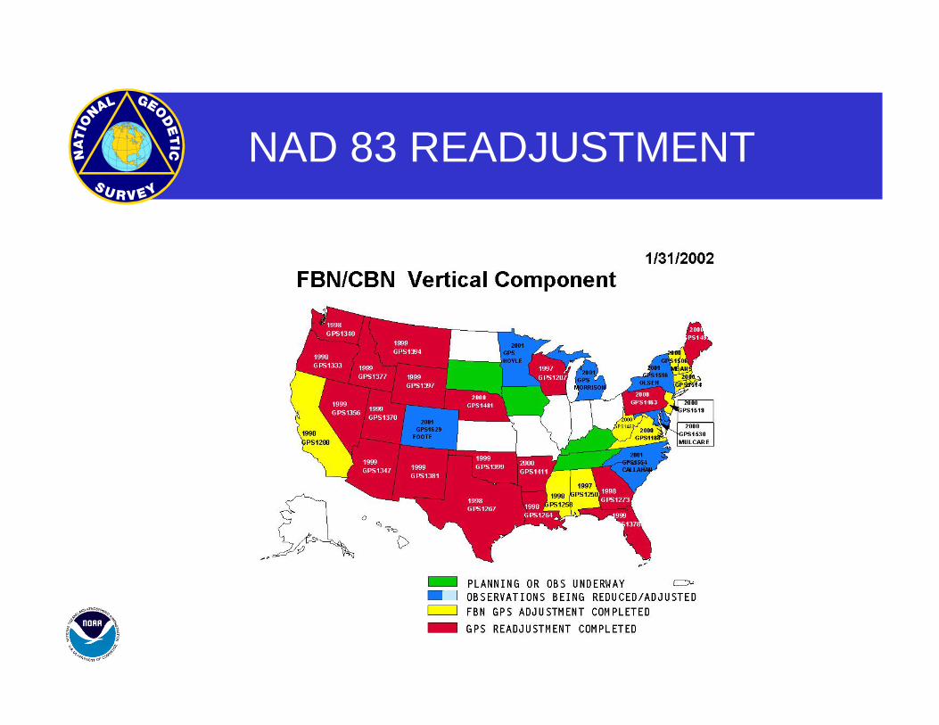
NAD 83 READJUSTMENT
NAD 83 READJUSTMENT
ONLY GPS DATA CONTINUOUSLY OPERATING REFERENCE STATIONS
FEDERAL BASE NETWORK COOPERATIVE BASE NETWORK
AIRPORT SURVEYS USER DENSIFICATION NETWORK
SPECIAL SURVEYS
NEW STANDARDS FOR GEODETIC CONTROL
Two accuracy standards (http://fgdc.er.usgs.gov/standards/status/swgstat.html) local accuracy ------------- adjacent points network accuracy ---------- relative to CORS
Numeric quantities, units in cm (or mm) Both are relative accuracy measures Do not use distance dependent expression Horizontal accuracies are radius of 2-D 95% error circle Ellipsoidal/Orthometric heights are 1-D (linear) 95% error
DATUM TRANSFORMATIONS
1. WHAT DATUM ARE THE EXISTING COORDINATES ON? 2. WHAT DATUM DO I WANT THE NEW COORDINATES ON? 3. HOW LARGE A GEOGRAPHICAL AREA DO I WANT TO CONVERT
AT ONE TIME? 4. HOW MANY POINTS ARE COMMON TO BOTH DATUMS? 5. WHAT IS THE DISTRIBUTION OF THE COMMON POINTS? 6. HOW ACCURATE ARE THE EXISTING COORDINATES?
0.1 Foot 1.0 Foot 10. Feet
7. HOW ACCURATE DO I WANT THE NEW COORDINATES?
DATUM TRANSFORMATIONS
MOLODENSKY
Converts latitude, longitude and ellipsoidal height to X,Y,Z Earth-Centered Coordinates.
Applies a 3-dimensional change in the origin (dX, dY,dZ) Applies a change in the size and shape of the reference ellipsoid
Converts new X,Y,Z Earth-Centered Coordinates back to latitude, longitude and ellipsoidal height
DATUM TRANSFORMATIONS
MOLODENSKY
For continental regions accuracy can be +/- 8 to 10 meters
Does not model network distortions very well.
Assumes heights in both systems are ellipsoidal (NAD 27 did not have ellipsoidal heights).
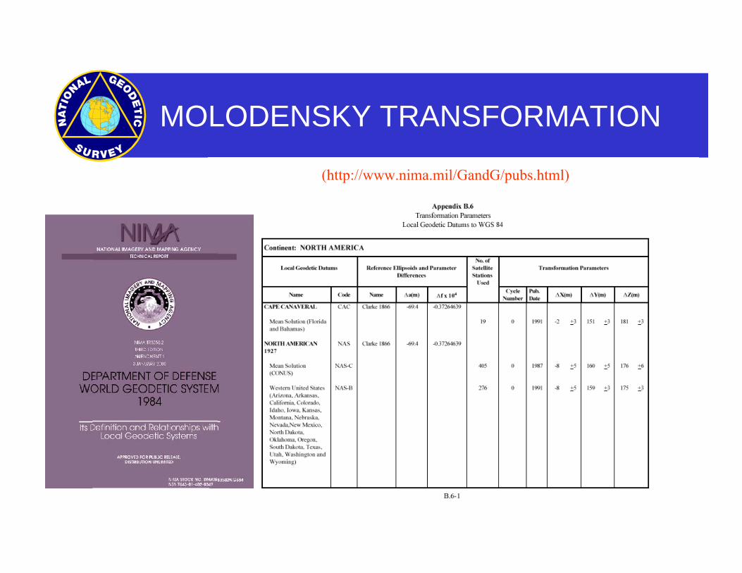
MOLODENSKY TRANSFORMATION
(http://www.nima.mil/GandG/pubs.html)
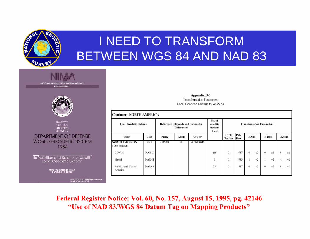
I NEED TO TRANSFORMBETWEEN WGS 84 AND NAD 83
Federal Register Notice: Vol. 60, No. 157, August 15, 1995, pg. 42146“Use of NAD 83/WGS 84 Datum Tag on Mapping Products”
DATUM TRANSFORMATION –IDEAL METHOD
• SATISFIES ALL USERS’ REQUIREMENTS
• CAPABLE OF TRANSFORMING LARGE HOLDINGS OF COORDINATE DATA
• NEAR-REAL TIME APPLICATIONS
• SIMPLE - METHOD SHOULD NOT REQUIRE AN EXPERT OR DECISIONS TO BE MADE
• ACCURATE
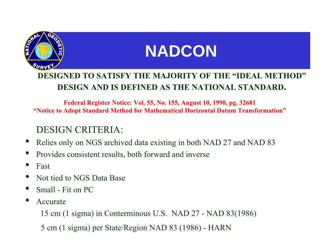
NADCON DESIGNED TO SATISFY THE MAJORITY OF THE “IDEAL METHOD”
DESIGN AND IS DEFINED AS THE NATIONAL STANDARD.
DESIGN CRITERIA:• Relies only on NGS archived data existing in both NAD 27 and NAD 83• Provides consistent results, both forward and inverse• Fast• Not tied to NGS Data Base• Small - Fit on PC• Accurate 15 cm (1 sigma) in Conterminous U.S. NAD 27 - NAD 83(1986)
5 cm (1 sigma) per State/Region NAD 83 (1986) - HARN
Federal Register Notice: Vol. 55, No. 155, August 10, 1990, pg. 32681“Notice to Adopt Standard Method for Mathematical Horizontal Datum Transformation”
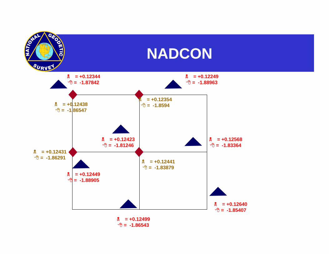
NADCON = +0.12344
= -1.87842 = +0.12249
= -1.88963
= +0.12423= -1.81246
= +0.12568= -1.83364
= +0.12449= -1.88905
= +0.12499= -1.86543
= +0.12640= -1.85407
= +0.12438= -1.86547
= +0.12354= -1.8594
= +0.12431= -1.86291
= +0.12441= -1.83879
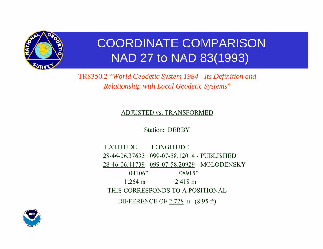
COORDINATE COMPARISONNAD 27 to NAD 83(1993)
TR8350.2 “World Geodetic System 1984 - Its Definition and Relationship with Local Geodetic Systems”
ADJUSTED vs. TRANSFORMED
Station: DERBY
LATITUDE LONGITUDE 28-46-06.37633 099-07-58.12014 - PUBLISHED 28-46-06.41739 099-07-58.20929 - MOLODENSKY .04106” .08915” 1.264 m 2.418 m
THIS CORRESPONDS TO A POSITIONAL
DIFFERENCE OF 2.728 m (8.95 ft)
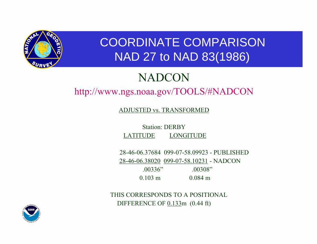
COORDINATE COMPARISONNAD 27 to NAD 83(1986)
NADCON http://www.ngs.noaa.gov/TOOLS/#NADCON
ADJUSTED vs. TRANSFORMED
Station: DERBY LATITUDE LONGITUDE
28-46-06.37684 099-07-58.09923 - PUBLISHED 28-46-06.38020 099-07-58.10231 - NADCON
.00336” .00308” 0.103 m 0.084 m
THIS CORRESPONDS TO A POSITIONAL DIFFERENCE OF 0.133m (0.44 ft)
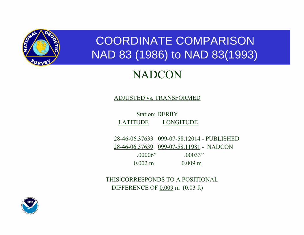
COORDINATE COMPARISONNAD 83 (1986) to NAD 83(1993)
NADCON
ADJUSTED vs. TRANSFORMED
Station: DERBY LATITUDE LONGITUDE
28-46-06.37633 099-07-58.12014 - PUBLISHED 28-46-06.37639 099-07-58.11981 - NADCON .00006” .00033” 0.002 m 0.009 m
THIS CORRESPONDS TO A POSITIONAL DIFFERENCE OF 0.009 m (0.03 ft)
GPS NETWORKS TO SUPPORT GIS
GPS SURVEY DATA
OBSERVE TO NATIONAL STANDARDS
TIES TO CORS, HARN and LOCAL BMs
QUALITY MONUMENTATION

GPS NETWORKS TO SUPPORT GIS
“CLASSICAL” Lots of control points spaced at regular intervals
(1-3 miles)
“CONTEMPORARHY” CORS and Monumentation as needed
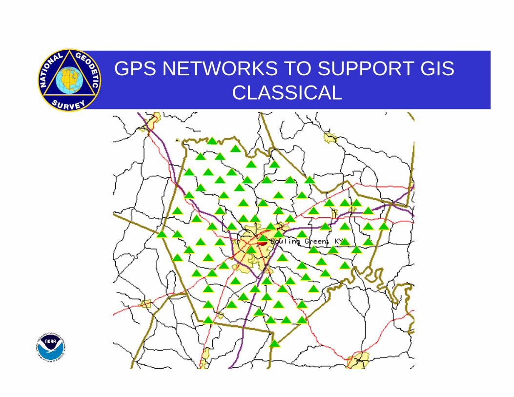
GPS NETWORKS TO SUPPORT GISCLASSICAL
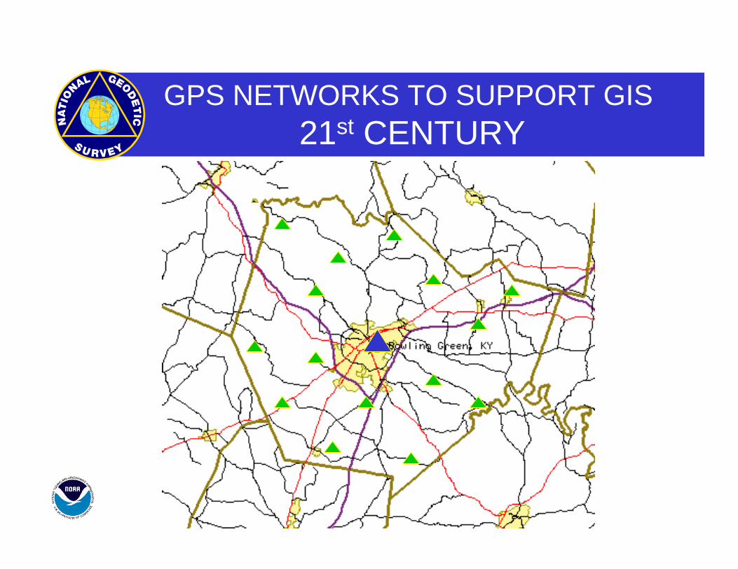
GPS NETWORKS TO SUPPORT GIS21st CENTURY
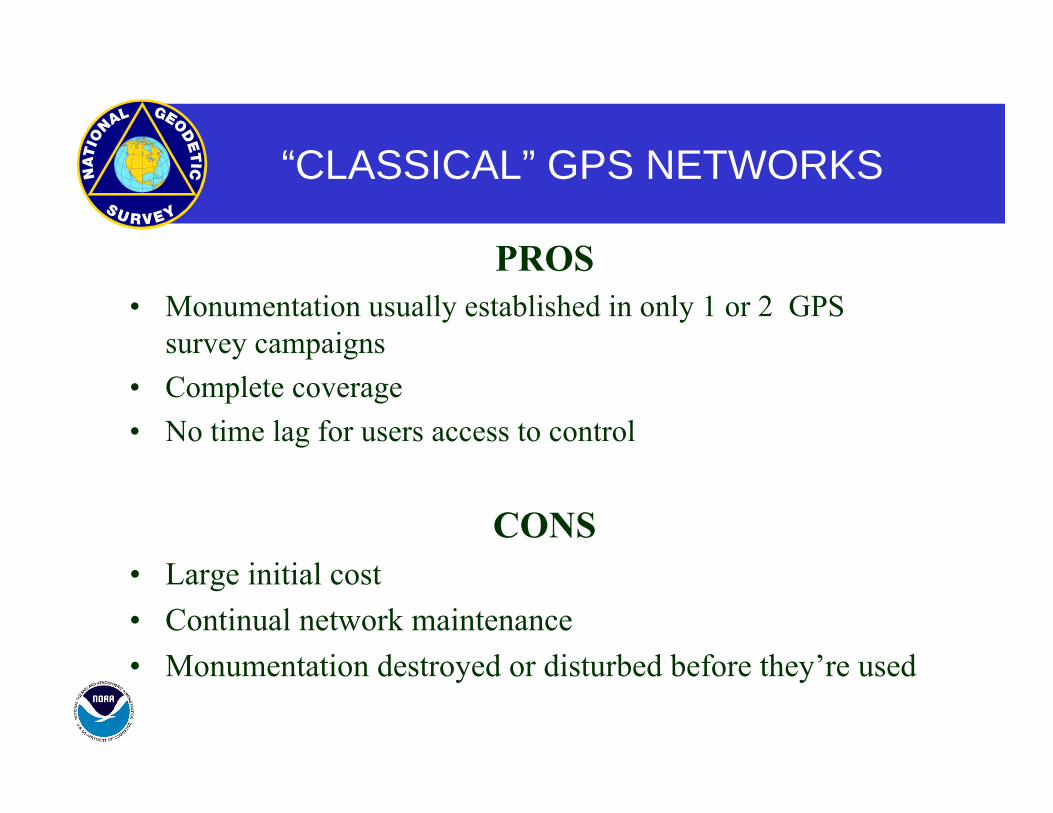
“CLASSICAL” GPS NETWORKS
PROS• Monumentation usually established in only 1 or 2 GPS
survey campaigns• Complete coverage• No time lag for users access to control
CONS• Large initial cost• Continual network maintenance• Monumentation destroyed or disturbed before they’re used
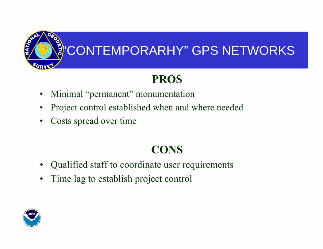
“CONTEMPORARHY” GPS NETWORKS
PROS• Minimal “permanent” monumentation• Project control established when and where needed• Costs spread over time
CONS• Qualified staff to coordinate user requirements• Time lag to establish project control
GPS NETWORKS TO SUPPORT GIS
GPS SURVEY DATA
“BLUE - BOOK” SUBMISSION OF DATA FOR INCLUSION IN NSRS
OR
DATA MAINTAINED AT THE LOCAL LEVEL
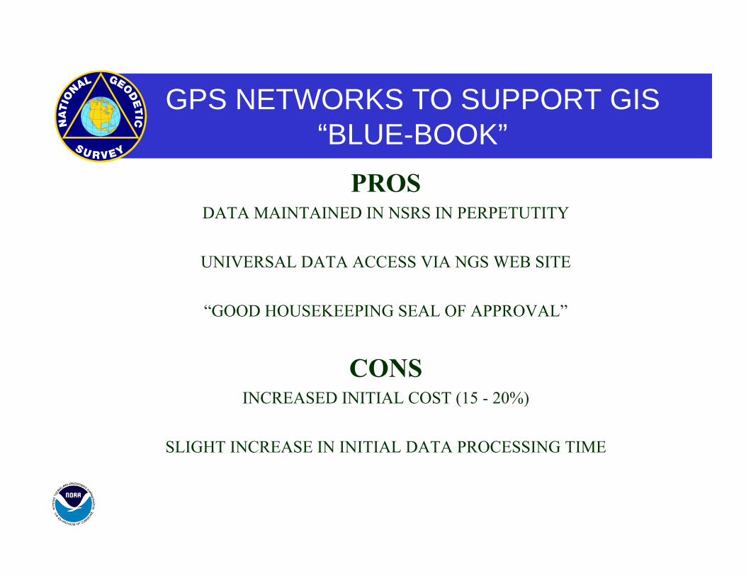
GPS NETWORKS TO SUPPORT GIS“BLUE-BOOK” PROS
DATA MAINTAINED IN NSRS IN PERPETUTITY
UNIVERSAL DATA ACCESS VIA NGS WEB SITE
“GOOD HOUSEKEEPING SEAL OF APPROVAL”
CONS INCREASED INITIAL COST (15 - 20%)
SLIGHT INCREASE IN INITIAL DATA PROCESSING TIME

GPS NETWORKS TO SUPPORT GISLOCAL MAINTENANCE
PROS DECREASED INITIAL SURVEY COSTS
LOCAL CONTROL OF ALL DATA
CONS READJUSTMENTS TO FUTURE REFERENCE FRAME CHANGES
MUST BE DONE AT THE LOCAL LEVEL
DATA MAY BE DIFFICULT TO LOCATE FOR “NON-LOCALS”
GOOD COORDINATION BEGINS WITH GOOD COORDINATES
GEOGRAPHY WITHOUT GEODESY IS A FELONY
References:References:
•• http://www.trimble.com/gps/whatgps.shtmlhttp://www.trimble.com/gps/whatgps.shtml
• http://www.ngs.noaa.gov
• …….